JP5295241B2 - Three-phase multi-winding device - Google Patents
Three-phase multi-winding device Download PDFInfo
- Publication number
- JP5295241B2 JP5295241B2 JP2010523153A JP2010523153A JP5295241B2 JP 5295241 B2 JP5295241 B2 JP 5295241B2 JP 2010523153 A JP2010523153 A JP 2010523153A JP 2010523153 A JP2010523153 A JP 2010523153A JP 5295241 B2 JP5295241 B2 JP 5295241B2
- Authority
- JP
- Japan
- Prior art keywords
- hub
- winding
- outer shell
- winding device
- slot
- Prior art date
- Legal status (The legal status is an assumption and is not a legal conclusion. Google has not performed a legal analysis and makes no representation as to the accuracy of the status listed.)
- Expired - Fee Related
Links
Images


Classifications
-
- H—ELECTRICITY
- H01—ELECTRIC ELEMENTS
- H01F—MAGNETS; INDUCTANCES; TRANSFORMERS; SELECTION OF MATERIALS FOR THEIR MAGNETIC PROPERTIES
- H01F30/00—Fixed transformers not covered by group H01F19/00
- H01F30/06—Fixed transformers not covered by group H01F19/00 characterised by the structure
- H01F30/12—Two-phase, three-phase or polyphase transformers
- H01F30/14—Two-phase, three-phase or polyphase transformers for changing the number of phases
-
- H—ELECTRICITY
- H01—ELECTRIC ELEMENTS
- H01F—MAGNETS; INDUCTANCES; TRANSFORMERS; SELECTION OF MATERIALS FOR THEIR MAGNETIC PROPERTIES
- H01F27/00—Details of transformers or inductances, in general
- H01F27/24—Magnetic cores
-
- H—ELECTRICITY
- H01—ELECTRIC ELEMENTS
- H01F—MAGNETS; INDUCTANCES; TRANSFORMERS; SELECTION OF MATERIALS FOR THEIR MAGNETIC PROPERTIES
- H01F41/00—Apparatus or processes specially adapted for manufacturing or assembling magnets, inductances or transformers; Apparatus or processes specially adapted for manufacturing materials characterised by their magnetic properties
- H01F41/02—Apparatus or processes specially adapted for manufacturing or assembling magnets, inductances or transformers; Apparatus or processes specially adapted for manufacturing materials characterised by their magnetic properties for manufacturing cores, coils, or magnets
- H01F41/04—Apparatus or processes specially adapted for manufacturing or assembling magnets, inductances or transformers; Apparatus or processes specially adapted for manufacturing materials characterised by their magnetic properties for manufacturing cores, coils, or magnets for manufacturing coils
- H01F41/06—Coil winding
- H01F41/071—Winding coils of special form
- H01F2041/0711—Winding saddle or deflection coils
-
- H—ELECTRICITY
- H02—GENERATION; CONVERSION OR DISTRIBUTION OF ELECTRIC POWER
- H02M—APPARATUS FOR CONVERSION BETWEEN AC AND AC, BETWEEN AC AND DC, OR BETWEEN DC AND DC, AND FOR USE WITH MAINS OR SIMILAR POWER SUPPLY SYSTEMS; CONVERSION OF DC OR AC INPUT POWER INTO SURGE OUTPUT POWER; CONTROL OR REGULATION THEREOF
- H02M1/00—Details of apparatus for conversion
- H02M1/12—Arrangements for reducing harmonics from ac input or output
-
- H—ELECTRICITY
- H02—GENERATION; CONVERSION OR DISTRIBUTION OF ELECTRIC POWER
- H02M—APPARATUS FOR CONVERSION BETWEEN AC AND AC, BETWEEN AC AND DC, OR BETWEEN DC AND DC, AND FOR USE WITH MAINS OR SIMILAR POWER SUPPLY SYSTEMS; CONVERSION OF DC OR AC INPUT POWER INTO SURGE OUTPUT POWER; CONTROL OR REGULATION THEREOF
- H02M5/00—Conversion of ac power input into ac power output, e.g. for change of voltage, for change of frequency, for change of number of phases
- H02M5/02—Conversion of ac power input into ac power output, e.g. for change of voltage, for change of frequency, for change of number of phases without intermediate conversion into dc
- H02M5/04—Conversion of ac power input into ac power output, e.g. for change of voltage, for change of frequency, for change of number of phases without intermediate conversion into dc by static converters
- H02M5/10—Conversion of ac power input into ac power output, e.g. for change of voltage, for change of frequency, for change of number of phases without intermediate conversion into dc by static converters using transformers
- H02M5/14—Conversion of ac power input into ac power output, e.g. for change of voltage, for change of frequency, for change of number of phases without intermediate conversion into dc by static converters using transformers for conversion between circuits of different phase number
-
- Y—GENERAL TAGGING OF NEW TECHNOLOGICAL DEVELOPMENTS; GENERAL TAGGING OF CROSS-SECTIONAL TECHNOLOGIES SPANNING OVER SEVERAL SECTIONS OF THE IPC; TECHNICAL SUBJECTS COVERED BY FORMER USPC CROSS-REFERENCE ART COLLECTIONS [XRACs] AND DIGESTS
- Y02—TECHNOLOGIES OR APPLICATIONS FOR MITIGATION OR ADAPTATION AGAINST CLIMATE CHANGE
- Y02E—REDUCTION OF GREENHOUSE GAS [GHG] EMISSIONS, RELATED TO ENERGY GENERATION, TRANSMISSION OR DISTRIBUTION
- Y02E40/00—Technologies for an efficient electrical power generation, transmission or distribution
- Y02E40/40—Arrangements for reducing harmonics
-
- Y—GENERAL TAGGING OF NEW TECHNOLOGICAL DEVELOPMENTS; GENERAL TAGGING OF CROSS-SECTIONAL TECHNOLOGIES SPANNING OVER SEVERAL SECTIONS OF THE IPC; TECHNICAL SUBJECTS COVERED BY FORMER USPC CROSS-REFERENCE ART COLLECTIONS [XRACs] AND DIGESTS
- Y10—TECHNICAL SUBJECTS COVERED BY FORMER USPC
- Y10T—TECHNICAL SUBJECTS COVERED BY FORMER US CLASSIFICATION
- Y10T29/00—Metal working
- Y10T29/49—Method of mechanical manufacture
- Y10T29/49002—Electrical device making
- Y10T29/4902—Electromagnet, transformer or inductor
- Y10T29/49071—Electromagnet, transformer or inductor by winding or coiling
Description
B.関連出願及び優先権主張
本願は、その各々が本明細書で援用している2007年8月29日に出願された米国仮出願第60/968,577号、2007年8月29日に出願された米国仮出願第60/968,584号、及び、2007年8月29日に出願された米国仮出願第60/968,610号の優先権の特典を主張するものである。
C−E.該当なし
B. RELATED APPLICATION AND PRIORITY CLAIM This application is filed on August 29, 2007, US Provisional Application No. 60 / 968,577, filed on August 29, 2007, each of which is incorporated herein by reference. US Provisional Application No. 60 / 968,584 and US Provisional Application No. 60 / 968,610 filed on Aug. 29, 2007, are claimed.
CE Not applicable
本発明は、一般に及び様々な実施形態において小型三相多巻線装置に関する。 The present invention relates generally and in various embodiments to small three-phase multi-winding devices.
長年にわたって、三相変圧器は、一般に3つの脚を備える積層鉄心に取り付けられた銅又はアルミニウム巻線からなる3つのコイルによって構成されてきた。しかし、従来の3脚鉄心設計は、必ずしもあらゆる場合に最適な設計ではなかった。例えば従来の3脚鉄心設計には比較的多量のスペースが必要とされるので、この設計は多くの用途において必ずしも最適な設計ではなかった。 Over the years, three-phase transformers have been constructed with three coils consisting of copper or aluminum windings attached to a laminated core that generally has three legs. However, the conventional three-legged iron core design is not necessarily the optimum design in all cases. For example, the conventional three-legged iron core design requires a relatively large amount of space, so this design is not necessarily the optimum design for many applications.
従来の3脚変圧器が、各々特定の電圧及び位相角を有する多数の三相二次巻線を必要とする用途の場合、二次巻線は、一般に各コイルから2つの構成巻線(即ち全部で3つのコイルから合計で6つの構成巻線)を必要とする。こうした用途の場合、二次巻線は、例えば、辺延び三角形状、ジグザグ形状又は多角形状をなすように構成できる。いかなる巻線であれその全ての構成巻線の巻数は整数値が望ましいので、指定の電圧及び/又は位相角を正確に与えるのはほぼ不可能であり、一般に近似値が必要とされる。二次巻線が、一様な間隔で、公称電圧は同じであるが位相角が異なるという特定の場合、構成巻線における位相角に近似することが可能な整数値の巻数の選択は制限されるので、位相角が異なる二次巻線は強制的に電圧が異なる結果になる可能性がある。従来の3脚変圧器に関するもう1つの問題は、二次巻線が一次巻線に対して異なる結合係数を有するということである。 For applications where a conventional tripod transformer requires a large number of three-phase secondary windings, each having a specific voltage and phase angle, the secondary winding is typically two component windings (ie, from each coil). A total of six constituent windings from a total of three coils). For such applications, the secondary winding can be configured to have, for example, a side-extended triangle shape, a zigzag shape, or a polygonal shape. Since the number of turns of all constituent windings of any winding is desirable to be an integer value, it is almost impossible to accurately provide a specified voltage and / or phase angle, and an approximate value is generally required. In certain cases where the secondary windings are uniformly spaced, with the same nominal voltage but different phase angles, the choice of integer number of turns that can approximate the phase angle in the constituent windings is limited. Therefore, there is a possibility that the secondary windings having different phase angles are forced to have different voltages. Another problem with conventional tripod transformers is that the secondary winding has a different coupling coefficient with respect to the primary winding.
一般に、近似を物理的に実施する上での困難は、変圧器の相対的コストを増大させ、こうした近似に伴う誤差は変圧器内における高調波相殺を劣化させることにある。 In general, the difficulty in physically implementing the approximation is that it increases the relative cost of the transformer, and the errors associated with such an approximation degrade the harmonic cancellation within the transformer.
図1は、従来の三相変圧器3を含むAC駆動装置1を例示する。この変圧器は、一次巻線5と、複数の三相二次巻線7を含み、各巻線は特定の電圧と位相角を有している。AC駆動装置1の出力側において、ACモータの三相の各々が直列に接続された一連の電力セルによって駆動される。図1のAC駆動装置の場合、相毎にCELLA1〜A6、CELLB1〜B6及びCELLC1〜C6と表示した6つの電力セルが存在し、全部で18の電力セルになる。他の実施例の場合には、相毎に別の数のセル(例えば1つのセル、3つのセル、9つのセル等)とすることもできる。AC駆動装置又はAC電源に関して、各電力セルは、三相AC入力電力を受電して単相AC電圧を出力し、AC−DC整流器(再生式とすることが可能)、平滑フィルタ及び出力DC−AC変換器を含む装置である。 FIG. 1 illustrates an AC drive device 1 including a conventional three-phase transformer 3. This transformer includes a primary winding 5 and a plurality of three-phase secondary windings 7, each winding having a specific voltage and phase angle. On the output side of the AC drive device 1, each of the three phases of the AC motor is driven by a series of power cells connected in series. In the case of the AC driving device shown in FIG. 1, there are six power cells labeled CELLA1 to A6, CELLB1 to B6, and CELLC1 to C6 for each phase, resulting in a total of 18 power cells. In other embodiments, there may be a different number of cells per phase (eg, one cell, three cells, nine cells, etc.). With respect to an AC drive or AC power source, each power cell receives three-phase AC input power and outputs a single-phase AC voltage, an AC-DC rectifier (can be regenerative), a smoothing filter and an output DC- An apparatus including an AC converter.
図1のAC駆動装置の場合、変圧器3は、その一次巻線5にR、S及びTと表示したポイントで地域発電所から三相AC入力電力を受電する。各電力セルは、変圧器3の専用二次巻線7から三相AC入力電力を受電する。18個の二次巻線7は、公称電圧が同じであり、3ランクをなすように配列され、各ランクが6つの特定の公称位相角の1つを有している。10度の倍数単位で異なる公称位相角が辺延び三角形状を利用して近似されるが、図1の場合、全ての二次巻線の平均位相角がその基準とされる。異なる位相角は、変圧器内において高調波相殺を生じさせる働きをする。各二次巻線7には、6つの構成巻線、即ち3つの内側三角構成巻線と3つの外側延長構成巻線が含まれている。構成巻線は全て整数の巻数にすべきであり、その巻数又は相互接続は各位相角毎に異なる。 In the case of the AC drive device of FIG. 1, the transformer 3 receives the three-phase AC input power from the regional power plant at points indicated as R, S and T in the primary winding 5. Each power cell receives three-phase AC input power from the dedicated secondary winding 7 of the transformer 3. The 18 secondary windings 7 have the same nominal voltage and are arranged in three ranks, each rank having one of six specific nominal phase angles. In the case of FIG. 1, the average phase angle of all the secondary windings is used as a reference. The different phase angles serve to cause harmonic cancellation in the transformer. Each secondary winding 7 includes six component windings: three inner triangular component windings and three outer extension component windings. All constituent windings should have an integer number of turns, the number of turns or interconnections being different for each phase angle.
所定の一次コイル群に結合された二次巻線構成コイルは、その一次コイルの周りで互いに垂直方向に変位している。様々な二次構成巻線がコイルに沿って異なる軸方向位置にあるので、一次巻線5に対するそれらの結合係数は異なっている。これは、整数の巻数要件に起因する電圧及び位相角の誤差によって生じる劣化に加えて、高調波相殺を更に劣化させることになりがちである。更に、従来の変圧器3の構造には利用されない比較的多量のスペースがあるので、従来の変圧器の全体サイズは比較的大きい。 The secondary winding constituting coils coupled to the predetermined primary coil group are displaced in the vertical direction around the primary coil. Since the various secondary constituent windings are at different axial positions along the coil, their coupling coefficients for the primary winding 5 are different. This tends to further degrade harmonic cancellation in addition to degradation caused by voltage and phase angle errors due to integer turns requirements. Furthermore, since there is a relatively large amount of space that is not utilized in the structure of the conventional transformer 3, the overall size of the conventional transformer is relatively large.
1つの一般的な観点において、本明細書には三相多巻線装置を開示している。様々な実施形態によれば、この多巻線装置には、ハブとハブの外周を囲む外殻とを含む鉄心が含まれており、ハブと外殻は互いに対して固定位置についている。鉄心には、複数スロットも含まれている。鉄心以外に、多巻線装置には、スロットの少なくとも2つに配置された一次巻線と、空間的に分布した複数の二次巻線が含まれており、二次巻線の少なくとも1つは、その2つのスロットの少なくとも一方において一次巻線に近接して配置されている。 In one general aspect, a three-phase multi-winding device is disclosed herein. According to various embodiments, the multi-winding device includes an iron core that includes a hub and an outer shell surrounding the outer periphery of the hub, the hub and outer shell being in a fixed position relative to each other. The iron core also includes a plurality of slots. In addition to the iron core, the multi-winding device includes a primary winding disposed in at least two of the slots and a plurality of spatially distributed secondary windings, and at least one of the secondary windings. Are arranged in proximity to the primary winding in at least one of the two slots.
もう1つの一般的観点において、本願には指定の位相角のAC電圧を発生するための方法が開示される。様々な実施形態によれば、この方法には、三相多巻線装置の固定一次巻線に第1のAC電圧を印加するステップと、一次巻線にAC電流を通すステップと、三相多巻線装置の鉄心によって形成される対称軸周りを回転する放射状磁界を発生するステップと、三相多巻線装置の空間的に分布した複数の固定二次巻線に第2のAC電圧を誘導するステップを含んでいる。 In another general aspect, the present application discloses a method for generating an AC voltage of a specified phase angle. According to various embodiments, the method includes applying a first AC voltage to a fixed primary winding of a three-phase multi-winding device; passing an AC current through the primary winding; Generating a radial magnetic field that rotates about an axis of symmetry formed by the iron core of the winding device and inducing a second AC voltage across a plurality of spatially distributed fixed secondary windings of the three-phase multi-winding device Includes steps to do.
もう1つの一般的観点において、本明細書はある装置を開示する。様々な実施形態において、この装置は、複数の電力セルと、電力セルの各々に接続された多巻線装置を含んでいる。前述のように、多巻線装置には、ハブとハブの外周を囲む外殻とを含む鉄心が含まれており、ハブと外殻は互いに対して固定位置についている。鉄心には、複数スロットも含まれている。鉄心以外に、多巻線装置には、スロットの少なくとも2つに配置された一次巻線と、空間的に分布した複数の二次巻線が含まれており、二次巻線の少なくとも1つは、その2つのスロットの少なくとも一方におい一次巻線に近接して配置されている。 In another general aspect, this specification discloses an apparatus. In various embodiments, the apparatus includes a plurality of power cells and a multi-winding device connected to each of the power cells. As described above, the multi-winding device includes the iron core including the hub and the outer shell surrounding the outer periphery of the hub, and the hub and the outer shell are in a fixed position with respect to each other. The iron core also includes a plurality of slots. In addition to the iron core, the multi-winding device includes a primary winding disposed in at least two of the slots and a plurality of spatially distributed secondary windings, and at least one of the secondary windings. Are arranged in proximity to the primary winding in at least one of the two slots.
以下、下記の図を参照し、本発明の様々な実施形態について説明する。 Hereinafter, various embodiments of the present invention will be described with reference to the following drawings.
本方法、システム及び材料について述べる前に理解しておくべきは、本開示が記載の特定の方法論、システム及び材料に限定されるものではない点である。と言うのは、これらは変わる場合があるためである。更に理解すべきは、本説明において用いる用語は、特定のバージョン又は実施形態の説明だけを目的とするものであって、その範囲を制限することを意図したものではない。例えば本明細書及び付属の請求項において用いる限りにおいて、単数形の「1つの〜」、「ある〜」、及び、「その〜」には、文脈において明確に別段の指示がなければ複数の言及対象が含まれる。更に、本明細書で用いる「〜を含む」という用語は、「〜を含むが、それに限定されるわけではない」ことを表わすように意図されている。別段の定義がない限り、本明細書で用いる全ての技術用語及び科学用語は、通常の当該技術者によって一般に理解されているのと同じ意味を持つ。 It should be understood before describing the present methods, systems and materials that the present disclosure is not limited to the specific methodologies, systems and materials described. This is because these can change. It should be further understood that the terminology used in the present description is for the purpose of describing particular versions or embodiments only, and is not intended to limit the scope thereof. For example, as used in this specification and the appended claims, the singular forms “a”, “an”, “a” and “and” refer to the plural unless the context clearly dictates otherwise. The target is included. Further, as used herein, the term “including” is intended to mean “including but not limited to”. Unless defined otherwise, all technical and scientific terms used herein have the same meaning as commonly understood by one of ordinary skill in the art.
理解しておくべきは、本発明の図と説明の少なくとも一部は、本発明の明確な理解を得るために関連する要素に焦点を絞るように単純化しており、更には明瞭化のために削除しているが、当業者には分かるであろう他要素が、やはり本発明の一部を構成する可能性がある。しかし、こうした要素は当技術分野では周知のところであり、必ずしも本発明のより良い理解を容易にするものでもないので、ここではこうした要素の説明は行わない。 It should be understood that at least some of the drawings and descriptions of the present invention have been simplified to focus on the relevant elements in order to obtain a clear understanding of the present invention, and for the sake of clarity. While omitted, other elements that will be apparent to those skilled in the art may still form part of the present invention. However, these elements are well known in the art and do not necessarily facilitate a better understanding of the present invention, so they will not be described here.
図2は、小型三相多巻線装置2の実施形態を例示している。小型三相多巻線装置2は、実用的な任意の数の極(例えば2極、4極、6極等)を備えるモータのような構造として構成されている。小型三相多巻線装置2は、様々な用途に利用できる。例えば小型三相多巻線装置2は、複数の電力セルを備えた交流(AC)電源、複数の電力セルを備えたAC駆動装置、又は複数の電力セルを備えた直流(DC)電源等に利用できる。複数の電力セルを備えたAC電源の実施形態については、例えば本明細書で参考迄に援用しているHammondに対する米国特許第5,625,545号(「545特許」)に記載がある。複数の電力セルを備えたDC電源の様々な実施形態については、例えば本明細書で参考までに援用しているOpal他に対する米国特許第5,638,263号(「263特許」)に記載がある。DC電源に関連して、電力セルは、三相AC入力電力を受電して、単一DC電圧を出力し、AC−DC整流器(再生式とすることが可能)、平滑フィルタ及び出力DC−DC変換器を含む装置である。 FIG. 2 illustrates an embodiment of a small three-phase multi-winding device 2. The small three-phase multi-winding device 2 is configured as a motor-like structure having an arbitrary number of practical poles (for example, 2 poles, 4 poles, 6 poles, etc.). The small three-phase multi-winding device 2 can be used for various applications. For example, the small three-phase multi-winding device 2 can be used as an alternating current (AC) power source having a plurality of power cells, an AC driving device having a plurality of power cells, a direct current (DC) power source having a plurality of power cells, or the like. Available. An embodiment of an AC power supply with multiple power cells is described, for example, in US Pat. No. 5,625,545 to Hammond (the “545 patent”), which is incorporated herein by reference. Various embodiments of DC power supplies with multiple power cells are described, for example, in US Pat. No. 5,638,263 (“263 patent”) to Opal et al., Which is incorporated herein by reference. is there. In connection with the DC power source, the power cell receives three-phase AC input power, outputs a single DC voltage, an AC-DC rectifier (can be regenerative), a smoothing filter and an output DC-DC. A device including a transducer.
説明を簡単化すべく、小型三相多巻線装置2をAC駆動装置に関連して述べる。しかし明らかに、小型三相多巻線装置2は他の用途にも利用できる。図1に示すように、小型三相多巻線装置2は、円筒対称性の鉄心4を含んでいる。留意すべきは、円筒形状の鉄心は例証のために示したものであり、例えば三角対称性の鉄心といった他の幾何学形状を利用可能な点である。鉄心4の円周及び長さは用途によって変わる可能性がある。小型三相多巻線装置2には、一次巻線と位相偏移二次巻線も含まれている。明確化のため、鉄心内に配置された巻線部分は、図2では完全には例示しておらず、ただ巻線6として例示している。鉄心4は、任意の適合する方法で任意の適合する材料から製作できる。様々な実施形態によれば、鉄心4は透磁率の高い材料(例えば鋼又は第一鉄材料)から製作される。様々な実施形態によれば、鉄心4には鋼層のスタックが含まれる。これらの層は、鉄とシリコンの合金である電炉鋼の圧延シートから打抜くことができる。一次巻線と二次巻線は、ACモータの巻線と同様に鉄心4の周りに分布する。 For the sake of simplicity, the small three-phase multi-winding device 2 will be described in connection with an AC drive device. Obviously, however, the small three-phase multi-winding device 2 can be used for other applications. As shown in FIG. 1, the small three-phase multi-winding device 2 includes a cylindrically symmetric iron core 4. It should be noted that the cylindrical iron core is shown for illustrative purposes, and other geometric shapes such as a triangularly symmetric iron core can be used. The circumference and length of the iron core 4 may vary depending on the application. The small three-phase multi-winding device 2 also includes a primary winding and a phase-shifted secondary winding. For the sake of clarity, the winding part arranged in the iron core is not illustrated entirely in FIG. The core 4 can be made from any suitable material in any suitable manner. According to various embodiments, the iron core 4 is fabricated from a material with high magnetic permeability (eg, steel or ferrous material). According to various embodiments, the iron core 4 includes a stack of steel layers. These layers can be stamped from a rolled sheet of electric furnace steel, which is an alloy of iron and silicon. The primary winding and the secondary winding are distributed around the iron core 4 like the winding of the AC motor.
ACモータにおいて見出されるように、三相多巻線装置2の一次巻線に三相電圧を印加すると放射状磁界が発生し、これが時間経過につれて構造軸の周りを回転する。この回転磁界によって、鉄心4の周りに分布した様々な巻線構成要素内に電圧が誘導される。ある特定の巻線構成要素の場合、誘導電圧の位相角は、その特定の巻線構成要素が取り付けられた物理的角度によって決まる。鉄心4の高透磁率が、磁界の発生に必要な電流を最小限に抑える働きをする。二次巻線は、所望の電気的位相角に対応する物理的角度で鉄心4内に配置される。鉄心4が鋼のような磁性材料から製作される実施形態の場合、鉄心4によって形成されたスロット内に巻線の全てを配置できる。スロット数は、スロットが所望の物理的角度で配置されるように選択できる。 As found in AC motors, applying a three-phase voltage to the primary winding of the three-phase multi-winding device 2 generates a radial magnetic field that rotates about the structural axis over time. This rotating magnetic field induces voltages in various winding components distributed around the iron core 4. For a particular winding component, the phase angle of the induced voltage depends on the physical angle to which that particular winding component is attached. The high permeability of the iron core 4 serves to minimize the current required for generating the magnetic field. The secondary winding is disposed in the iron core 4 at a physical angle corresponding to the desired electrical phase angle. In the case of an embodiment in which the iron core 4 is made of a magnetic material such as steel, all of the windings can be placed in a slot formed by the iron core 4. The number of slots can be selected so that the slots are arranged at the desired physical angle.
AC駆動装置に用いる場合、巻線6は任意の数の極を有するように構成できる。極数が偶数の場合、磁界の各N極が対応するS極を備えることが確実になる。2つの極(1つのN極と1つのS極)が存在する場合、それらの極は各電気サイクル毎に構造周りを完全に1回転し、電気的位相角において利用可能な増分は360度をスロット数で割った値に等しい。4つの極が存在する場合、完全な1回転は2電気サイクルに相当し、電気的位相角における利用可能な増分は720度をスロット数で割った値に等しい。6つの極が存在する場合、完全な1回転は3電気サイクルに相当し、電気的位相角における利用可能な増分は1080度をスロット数で割った値に等しい。 When used in an AC drive, the winding 6 can be configured to have any number of poles. When the number of poles is an even number, it is ensured that each N pole of the magnetic field has a corresponding S pole. If there are two poles (one N pole and one S pole), they will make one complete revolution around the structure for each electrical cycle and the available increment in electrical phase angle will be 360 degrees. Equal to the number divided by the number of slots. If there are four poles, a complete revolution corresponds to two electrical cycles and the available increment in electrical phase angle is equal to 720 degrees divided by the number of slots. If there are 6 poles, a complete revolution corresponds to 3 electrical cycles and the available increment in electrical phase angle is equal to 1080 degrees divided by the number of slots.
図1の電力セル構成を備えたAC駆動装置に用いられる場合、電気的位相角において必要とされる増分は、例えば10度又はその倍数になると考えられる。従って、2極巻線を用いる場合、少なくとも36のスロットを備えることになる可能性がある(即ち360度を36のスロットで割ると、10度の増分になる)。4極巻線を用いる場合、少なくとも72のスロットを備えることになる可能性がある(即ち720度を72のスロットで割ると、10度の増分になる)。6極巻線を用いる場合、少なくとも108のスロットを備えることになる可能性がある(即ち1080度を108のスロットで割ると、10度の増分になる)。明瞭化のため、図1〜6には、2極巻線の場合の10度の位相角増分に相当する最小数(36)のスロットを示している。しかし、様々な用途のために他の極数が利用できることは明らかである。 When used in an AC drive with the power cell configuration of FIG. 1, the required increment in electrical phase angle would be, for example, 10 degrees or a multiple thereof. Thus, if a dipole winding is used, it is possible to have at least 36 slots (ie, dividing 360 degrees by 36 slots results in 10 degree increments). If a 4-pole winding is used, it is possible to have at least 72 slots (ie dividing 720 degrees by 72 slots results in 10 degree increments). If a 6 pole winding is used, it may have at least 108 slots (ie, dividing 1080 degrees by 108 slots results in 10 degree increments). For clarity, FIGS. 1-6 show a minimum number (36) of slots corresponding to a 10 degree phase angle increment for a dipole winding. However, it is clear that other pole numbers can be used for various applications.
下記の表には、上述のAC駆動装置と同様の装置における様々なセル数に対し、2極設計と6極設計の両方に必要とされる鉄心のスロット数を示している。2極設計では、最少のスロット数が可能になるが、各スロット毎に3つの二次構成コイルを保持することが必要になる。6極設計は、より多くのスロットが必要になるが、各スロット毎に保持する二次構成コイルを1つだけにすることが可能になる。 The table below shows the number of core slots required for both 2-pole and 6-pole designs for various cell numbers in devices similar to the AC drive described above. A two pole design allows for a minimum number of slots, but requires the retention of three secondary component coils for each slot. The 6-pole design requires more slots but allows only one secondary component coil to be held for each slot.

図3と4は、小型三相多巻線装置の鉄心の様々な実施形態を例示している。鉄心(従って用いられる場合には成層材スタック)には、第1部材12と、第1部材12の少なくとも一部を包囲する第2部材14が含まれている。第1及び第2部材12、14は、一方がもう一方に対して移動しないという点で回転不能である。第1部材12は鉄心の「内側」部材とみなし、第2部材14は「外側」部材とみなすことができる。例示の実施形態の場合、第1部材12は、ホイールのハブ及びスポークに似るように構成されており、第2部材14は、ホイールのリム又は外殻に似るように構成されている。
3 and 4 illustrate various embodiments of the iron core of a small three-phase multi-winding device. The iron core (and thus the stratified stack if used) includes a
図3と4の場合、第1部材12には、ハブ16と、ハブ16に接続又は一体化された複数のスポーク18が含まれている。ハブ16には、表面20と裏面22が含まれている。スポーク18は、表面20の周りに等間隔に並んでおり、表面20と協働して、表面20の周りに等間隔に並んだ複数のスロット24を形成している。明瞭化のため図3と4には示さないが、小型三相多巻線装置の一次巻線と二次巻線がスロット24を占めている。裏面22により、鉄心の中心を通る開口26が形成されている。様々な実施形態によれば、ハブ16はソリッドハブ(即ち鉄心の中心を通る開口がない)となし得る。
3 and 4, the
第2部材、即ち外殻14には、表面28と裏面30が含まれている。表面28は第2部材14の外面、裏面30は第2部材14の内面とみなし得る。裏面30により第1部材12を収容するサイズの開口32が形成されている。図3と4の場合、開口32は第1部材12で部分的に覆われている。第1部材12が第2部材14により包囲されると、第1部材12と第2部材14により、その間(即ちスポーク18と第2部材14の裏面30の間)に間隔34が形成される。他の実施形態では、第2部材14は第1部材12と一体化している。この場合には、第1部材12と第2部材14の間に間隔は生じない。
The second member, or outer shell 14, includes a
図5は、小型三相多巻線装置の鉄心の他の様々な実施形態を例示する。鉄心、従って用いられる場合には成層材スタックには、第1部材40と、第1部材40を包囲する第2部材42が含まれている。第1部材40は、鉄心の「内側」部材とみなすことができ、第2部材42は、「外側」部材とみなし得る。
FIG. 5 illustrates various other embodiments of the iron core of a small three-phase multi-winding device. The iron core, and thus the stratified stack, if used, includes a
第1部材40には、ハブ44と、ハブ44に接続又は一体化された複数のスポーク46が含まれている。ハブ44には、表面48と裏面50が含まれている。スポーク46は、表面48の周りに等間隔に並んでおり、表面48と協働して、表面48の周りに等間隔に並んだ複数のスロット52を形成している。明瞭化のため図5には示していないが、小型三相多巻線装置の一次巻線及び/又は二次巻線がスロット52を占めている。裏面50によって、鉄心の中心を通る開口54が形成されている。様々な実施形態によれば、ハブ44はソリッドハブ(即ち鉄心の中心を通る開口がない)となし得る。
The
第2部材42には、リム56と、リム56に接続又は一体化された複数のスポーク58が含まれている。リム56には、表面60と裏面62が含まれている。スポーク58は、裏面62の周りに等間隔に並んでおり、スポーク46とアライメントがとられ、スポーク46から間隔をあけて配置されている。スポーク46、58は、図5では長さがほぼ等しいように示しているが、スポーク46の長さはスポーク58の長さより短く或いは長くすることもできる。スポーク58は裏面62と協働して、裏面62の周りに等間隔に並んだ複数のスロット64を形成している。明瞭化のため図5には示さないが、小型三相多巻線装置の一次及び/又は二次巻線もスロット64を占めている。スロット64は、スロット52とアライメントがとられている。スポーク58によって、第1部材40を収容するサイズの開口66が形成されている。図5の場合、開口66は第1部材40によって部分的に覆われている。第1部材40が第2部材42によって包囲されると、第1部材40と第2部材42によって、その間(即ち、スポーク46とスポーク58の間)に間隔68が形成される。様々な実施形態によれば、第2部材42は第1部材40と一体化している。こうした実施形態の場合、第1部材40と第2部材42の間に間隔は生じない。
The second member 42 includes a
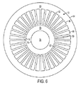
図6は、小型三相多巻線装置の鉄心の更なる他の様々な実施形態を例示している。鉄心(従って用いられる場合には成層材スタック)には、第1部材70と、第1部材70を包囲する第2部材72が含まれている。第1部材70は、鉄心の「内側」部材、そして第2部材72は、「外側」部材とみなし得る。
FIG. 6 illustrates various other embodiments of the iron core of a small three-phase multi-winding device. The iron core (and thus the stratified material stack, if used) includes a first member 70 and a
第1部材70には表面74と裏面76が含まれている。裏面76によって、鉄心の中心を通る開口78が形成されている。他の実施形態によれば、第1部材70はソリッド部材(即ち鉄心の中心を通る開口がない)となし得る。
The first member 70 includes a front surface 74 and a back surface 76. An
第2部材72は、リム80と、リム80に接続又は一体化された複数のスポーク82を含み、リム80は、表面84と裏面86を含んでいる。スポーク82は、裏面86の周りに等間隔に並んでおり、裏面86と協働して、裏面86の周りに等間隔に並んだ複数のスロット88を形成している。明瞭化のため図6には示さないが、小型三相多巻線装置の一次及び/又は二次巻線がスロット86を占めている。スポーク82により第1部材70を収容するサイズの開口90が形成されている。図6では、開口90は第1部材70により部分的に覆われている。第1部材70が第2部材72で包囲されると、第1部材70と第2部材72により、その間(即ち第1部材70の表面74とスポーク82の間)に間隔92が形成される。他の実施形態では、第2部材72は第1部材70と一体化している。この実施形態の場合、第1部材70と第2部材72の間に間隔は生じない。
The
図3〜6に示す実施形態の各々に関して、磁界が各々の第1と第2部材を通って流れ、一次及び/又は二次巻線が各々のスロットを占めている。一次及び二次巻線は、全節又は短節構造をなすように構成できる。様々な実施形態では、一次巻線は鉄心の中心に近接して配置され、二次巻線は鉄心の中心からより遠くに配置されている。他の実施形態では、二次巻線は鉄心の中心に近接して配置され、一次巻線は鉄心の中心からより遠くに配置されている。一次及び/又は二次巻線が各々のスロットの全容積を占めない実施例では、ウェッジを利用し、スロットの残存容積を充填し得る。他の実施形態によれば、一次及び二次巻線の各々は、導電性材料(例えば銅)から製作され、導電材料を包囲する絶縁ジャケットを含んでいる。巻線の絶縁ジャケットにより、端巻部分に関し一次巻線と二次巻線の間及び異なる位相の一次巻線間に線間絶縁を施すことが可能になる。絶縁ジャケットによって、地絡を防止するため鉄心と巻線の間に線路接地絶縁を施すこともできる。 For each of the embodiments shown in FIGS. 3-6, a magnetic field flows through each first and second member, and a primary and / or secondary winding occupies each slot. The primary and secondary windings can be configured to have a full or short section structure. In various embodiments, the primary winding is disposed proximate to the center of the core and the secondary winding is disposed further from the center of the core. In other embodiments, the secondary winding is disposed proximate to the center of the iron core, and the primary winding is disposed further from the center of the iron core. In embodiments where the primary and / or secondary windings do not occupy the full volume of each slot, a wedge may be utilized to fill the remaining volume of the slot. According to another embodiment, each of the primary and secondary windings is made from a conductive material (eg, copper) and includes an insulating jacket surrounding the conductive material. The insulation jacket of the winding makes it possible to provide line insulation between the primary and secondary windings and between the primary windings of different phases for the end turns. The insulation jacket can also provide line ground insulation between the iron core and the windings to prevent ground faults.
図7は、10度の位相角増分を必要とし、図1に例示のような電力セル構成を施された、AC駆動装置に用いられる小型三相多巻線装置の様々な実施形態を例示している。単純化し、分かりやすくするため、図6に示す巻線構成は2極全節巻き構成である。しかし、明らかに他の構成(4極、6極、短節等)も利用できる。 FIG. 7 illustrates various embodiments of a miniature three-phase multi-winding device used in an AC drive that requires a 10 degree phase angle increment and has a power cell configuration as illustrated in FIG. ing. For simplicity and clarity, the winding configuration shown in FIG. 6 is a two-pole full-pitch winding configuration. However, obviously other configurations (4 poles, 6 poles, short bars etc.) can also be used.
図7は、最初にスロットの底部(即ちR、S及びTで表わした鉄心の中心に最も近いスロット部分)に取り付けられた一次巻線コイルを示しているが、取り付け順序は変わる場合もある。一次巻線の各位相は、直列、並列又はその任意の組合せで接続することが可能な6つのコイルから構成されている。各コイルは、1つのスロットを通って上方に延び、もう1つのスロットを通って構造周りを半分程(1磁極ピッチ)下方に戻る1巻き以上の導体を備えている。各コイルの上方側は「+」、各コイルの下方側は「−」と標記している。例えば図7では、位相Rの6つのコイルを上方側(「R+」)が11時と1時の間でそして下方側(「R−」)が5時と7時の間でスロット内に取り付けられている。位相Sの6つのコイルは、上方側(「S+」)が3時と5時の間でスロット内に、下方側(「S−」)が9時と11時の間でスロット内に取り付けられている。位相Tの6つのコイルは上方側(「T+」)が7時と9時の間でスロット内に、下方側(「T−」)が1時と3時の間でスロット内に取り付けられている。各位相毎に6つのコイルからなる群は、各々Rコイル群、Tコイル群及びSコイル群として識別される。 FIG. 7 shows the primary winding coil initially attached to the bottom of the slot (ie, the slot portion closest to the center of the iron core represented by R, S and T), but the order of attachment may vary. Each phase of the primary winding is composed of six coils that can be connected in series, parallel or any combination thereof. Each coil includes one or more turns that extend upward through one slot and return halfway (one pole pitch) around the structure through the other slot. The upper side of each coil is labeled “+”, and the lower side of each coil is labeled “−”. For example, in FIG. 7, six coils of phase R are mounted in the slot between the upper side (“R +”) between 11 o'clock and 1 o'clock and the lower side (“R−”) between 5 o'clock and 7 o'clock. The six coils of phase S are mounted in the slot between 3 o'clock and 5 o'clock on the upper side (“S +”) and in the slot between 9 o'clock and 11 o'clock on the lower side (“S−”). The six coils of phase T are mounted in the slot between 7 o'clock and 9 o'clock on the upper side (“T +”) and in the slot on the lower side (“T−”) between 1 o'clock and 3 o'clock. Groups of six coils for each phase are identified as R coil group, T coil group and S coil group, respectively.
各二次巻線には、1つのスロットを通って上方に延び、もう1つのスロットを通って構造周りを半分程(1磁極ピッチ)下方に戻る1巻き以上の導体を備える3つのコイルが含まれている。図7の場合、二次巻線コイルを、A、B又はCで始まり、数字1、2、3、4、5又は6が後続する符号により表示している。英字と数字を組み合わせることで、どのセル(例えば図7に示す、以下で詳述するセル)がその二次巻線コイルにより給電されるかを示すことが可能になる。英字によりセルの位相群が識別され、他方数字によりセルのランクが識別される。図8は典型的なコイルの略図である。図7では、各コイルの上方側を「+」で、他方各コイルの下方側を「−」で標記している。位相Rの6つの一次コイルと同じスロット内に取り付けられる二次コイルを、「R構成コイル」と称する。位相Tの6つの一次コイルと同じスロット内に取り付けられる二次コイルを、「T構成コイル」と称する。位相Sの6つの一次コイルと同じスロット内に取り付けられる二次コイルは、「S構成コイル」と称する。例えば複数セルを備える図7に示す電力供給システムに用いる場合、R構成コイル給電セルC1は、上方側(「C1R+」)が11時10分の位置でスロット内に取り付けられ、下方側(「C1R−」)が5時10分の位置でスロット内に取り付けられる。R構成コイル給電セルC2は、上方側(「C2R+」)が11時30分の位置で、そして下方側(「C2R−」)が5時30分の位置でスロット内に取り付けられる。C1RコイルとC2Rコイルの間における1スロットの変位により、それらの間に10度の位相角が発生する。 Each secondary winding includes three coils with one or more turns that extend upward through one slot and return halfway around the structure (one pole pitch) through the other slot. It is. In the case of FIG. 7, the secondary winding coil is indicated by a symbol that begins with A, B, or C and is followed by the numbers 1, 2, 3, 4, 5, or 6. Combining letters and numbers makes it possible to indicate which cells (eg, the cells shown in FIG. 7 and described in detail below) are powered by their secondary winding coils. Alphabetic characters identify cell phase groups, while numbers identify cell ranks. FIG. 8 is a schematic diagram of a typical coil. In FIG. 7, the upper side of each coil is marked with “+”, and the lower side of each coil is marked with “−”. A secondary coil installed in the same slot as the six primary coils of phase R is referred to as an “R component coil”. A secondary coil installed in the same slot as the six primary coils of phase T is referred to as a “T component coil”. A secondary coil installed in the same slot as the six primary coils of phase S is referred to as an “S component coil”. For example, when used in the power supply system shown in FIG. 7 having a plurality of cells, the R component coil power supply cell C1 is mounted in the slot on the upper side (“C1R +”) at 11:10 and the lower side (“C1R -") Is installed in the slot at 5:10. The R component coil feeding cell C2 is mounted in the slot at the upper side (“C2R +”) at 11:30 and the lower side (“C2R−”) at 5:30. A one-slot displacement between the C1R and C2R coils results in a 10 degree phase angle between them.
同様に、T構成コイル給電セルC1は、上方側(「C1T+」)が7時10分の位置、そして下方側(「C1T−」)が1時10分の位置でスロット内に取り付けられる。T構成コイル給電セルC2は、上方側(「C2T+」)が7時30分、そして下方側(「C2T−」)が1時30分の位置でスロット内に取り付けられる。C1TコイルとC2Tコイルの間での1スロットの変位により、それらの間に10度の位相角が発生する。 Similarly, the T-configuration coil power supply cell C1 is installed in the slot at the upper side (“C1T +”) at 7:10 and the lower side (“C1T−”) at 1:10. The T-configuration coil power supply cell C2 is mounted in the slot at the upper side (“C2T +”) at 7:30 and the lower side (“C2T−”) at 1:30. A one-slot displacement between the C1T and C2T coils results in a 10 degree phase angle between them.
このパターンについて引き続き述べると、S構成コイル給電セルC1は、上方側(「C1S+」)が3時10分の位置、そして下方側(「C1S−」)が9時10分の位置でスロット内に取り付けられる。S構成コイル給電セルC2は、上方側(「C2S+」)が3時30分の位置で、そして下方側(「C2S−」)が9時30分の位置でスロット内に取り付けられる。C1SコイルとC2Sコイルの間における1スロットの変位に伴い、それらの間に10度の位相角が発生する。 Continuing to describe this pattern, the S-configuration coil feeding cell C1 is placed in the slot at the upper side (“C1S +”) at the position of 3:10 and the lower side (“C1S−”) at the position of 9:10. It is attached. The S-configuration coil feeding cell C2 is mounted in the slot at the upper side (“C2S +”) at the position of 3:30 and the lower side (“C2S−”) at the position of 9:30. With the displacement of one slot between the C1S coil and the C2S coil, a phase angle of 10 degrees is generated between them.
この応用例では、AC駆動装置は、3つの独立した二次巻線において同じ位相角が繰り返される必要があるので(例えばある特定のランクにおける3つの電力セルに関し)、図7に示すように、各スロット毎に3つの二次巻線のための構成コイルが収容されている。例えばセルA1、B1及びC1は同じ位相角を必要とし、従ってコイルA1RとB1RはコイルC1Rと同じスロット内にあり、コイルA1TとB1TはコイルC1Tと同じスロット内にあり、コイルA1SとB1SはコイルC1Sと同じスロット内にある。 In this application, the AC driver needs to repeat the same phase angle in three independent secondary windings (eg for three power cells in a certain rank), so as shown in FIG. Each slot houses three constituent coils for the secondary winding. For example, cells A1, B1 and C1 require the same phase angle, so coils A1R and B1R are in the same slot as coil C1R, coils A1T and B1T are in the same slot as coil C1T, and coils A1S and B1S are coil It is in the same slot as C1S.
図7は、36のスロットを備えた2極構成を例示しているが、勿論、他の実施形態では他の極/スロット構成が利用される場合もある。実施例に応じ、極数の増加を利用して、幾つかの利点をもたらすことが可能となる。2極の場合、全磁束が鉄心周りを半分程(1磁極ピッチ)流れ、従って、第1及び第2部材における鋼はそれに応じたサイズにせねばならない。6極構成を利用すると、全磁束の1/3だけが鉄心周りを60度(1磁極ピッチ)流れるので、第1及び第2部材の鋼を約2/3程減らすことが可能になる。2極の場合、各コイルの端巻部分は、鉄心を半分ほど(1磁極ピッチ)巻くのに十分な長さが必要とされる。例えば10度の位相角増分を必要とし、6極構成をなすAC駆動装置の場合、端巻部分は鉄心を60度(1磁極ピッチ)巻きさえすればよく、導体材料の節約になり、電力の損失が減少する。実施例によっては、スロット数の増加を利用して、幾つかの利点をもたらすことが可能となる。36のスロットの場合、一次巻線からの構成コイルに加えて、3つの二次巻線の各々の構成コイルが各スロット内に配置される。108のスロットの場合、ある特定の二次巻線の1つの構成コイルだけが各スロットを占めさえすればよく二次コイル間の絶縁を軽減することが可能になる。
Although FIG. 7 illustrates a two pole configuration with 36 slots, of course, other pole / slot configurations may be utilized in other embodiments. Depending on the embodiment, the increased number of poles can be used to provide several advantages. In the case of two poles, the total magnetic flux flows about half of the iron core (one pole pitch), so the steel in the first and second members must be sized accordingly. When the 6-pole configuration is used, only 1/3 of the total magnetic flux flows around the iron core by 60 degrees (one magnetic pole pitch), so that the steel of the first and second members can be reduced by about 2/3. In the case of two poles, the end winding portion of each coil is required to have a length sufficient to wind the iron core about half (one magnetic pole pitch). For example, in the case of an AC drive device that requires a phase angle increment of 10 degrees and has a 6-pole configuration, the end winding portion only needs to wind the
図8は、図7の小型三相多巻線装置のコイル100のワイヤフレーム略図を例示する。コイルの一部が、例えば図2に示す如く鉄心の2つのスロットに取り付けられている(例えば図8に示すようにスロット102aを通って上方に、スロット102bを通って下方に延びている)。コイルの残りの部分には、導体が1つのスロットからもう1つのスロットに移る端巻部分104が含まれている。端巻部分104は、鉄心材料の回転磁界と相互作用しないので二次巻線電圧の一因とはならないが、それでも電流を流し、従って電力損失を生じる。図8の点線はスロット102a及び102bのスロット開口を示すが、勿論一般には各スロット毎に少なくとも2つのコイル(一次巻線に対して1つと二次巻線に対して1つ)が存在するので、コイル断面積はスロット断面積より小さい。上述の如く、他の実施形態によれば、ある特定のスロットには2つ以上(例えば2つ)の一次巻線に対するコイル及び/又は2つ以上(例えば3つ)の二次巻線に対するコイルが存在し得る。
FIG. 8 illustrates a wire frame schematic of the
図9は、交互構成をなす鉄心層の1つ110の一部に関する断面を例示している。ここで、内側部材16は、長さが変化する一連の一体化スポーク又は延長部114を備えたセグメント112から組み立てられ、同様に、外側部材14はセグメント116から組み立てられている。図9に示す例の場合、各交互スポーク114は、隣接するスポークに比べて長いか短いかの何れかである。外殻セグメント116は、従って、各スポークを受け入れるよう構成される。鉄心の各層は、層110と同様に構成されるが、組立て中、各層を少なくともスポーク1つ分回転させて、短い方のスポークが長い方のスポークの上に位置し、鉄心の組立て完了時にスポークの交互配置パターンが形成されるようにする。交互配置パターンを与えることで、組立て中に結果として生じる空隙(特にスポーク114に対する外殻116の接合中に生じる空隙)がなくなるか或いは大幅に縮小される。セグメント間の空隙もこの交互配置法によって縮小し又はなくなる。更なる利点には、大きい鉄心の場合、セグメントは完全な円形積層に比べて打抜きがより容易であり、結果として屑材料が減少し、かつ取扱いがより容易になる可能性がある。
FIG. 9 illustrates a cross-section for a portion of one of the alternating core layers 110. Here, the inner member 16 is assembled from a
同様に、鉄心の各層は幾つかのセグメント(例えば9つのセグメント)から組立て、互いに隣接配置して単一層を形成し得る。図9に例示の層110は、セグメント118a、118b、118c及び118dからなっている。鉄心の組立て中、個別の層を積層すると、セグメント化部分によって生じる継目(例えば118aと118bとの間の継目)は上方の層と下方の層のセグメントによって覆われ、結果として、セグメント継目に関する交互配置パターンが形成される。
Similarly, each layer of iron core can be assembled from several segments (eg, nine segments) and placed adjacent to each other to form a single layer. The layer 110 illustrated in FIG. 9 consists of
図10は、指定の位相角の電圧を発生するための方法150の様々な実施形態を例示する。方法150は、上述の小型三相多巻線装置により実施できる。説明を容易にすべく、方法150の説明は小型三相多巻線装置によるその実施に関連して行うことにする。 FIG. 10 illustrates various embodiments of a method 150 for generating a voltage of a specified phase angle. Method 150 can be performed by the small three-phase multi-winding device described above. For ease of explanation, the method 150 will be described in connection with its implementation by a small three-phase multi-winding device.
このプロセスはステップ152で始まり、三相AC電圧が小型三相多巻線装置の一次巻線に印加される。三相AC電圧は、一次巻線のRコイル群、Sコイル群、及び、Tコイル群の両端に印加できる。上述の如く、Rコイル群、Sコイル群及びTコイル群に、小型三相多巻線装置の周りのスロットに配置された「上方」側と「下方」側を有する様々な巻き導体が含まれている。 The process begins at step 152 where a three-phase AC voltage is applied to the primary winding of a small three-phase multiwinding device. A three-phase AC voltage can be applied across the R coil group, S coil group, and T coil group of the primary winding. As described above, the R coil group, the S coil group, and the T coil group include various winding conductors having an “upper” side and a “lower” side disposed in slots around the small three-phase multi-winding device. ing.
プロセスはステップ152からステップ154に進み、AC電流(例えば磁化電流)が一次巻線を構成する様々な巻き導体を流れる。プロセスはステップ154からステップ156に進み、一次巻線を流れるAC電流により小型三相多巻線装置の鉄心にAC磁束が生じる。換言すれば、一次巻線を流れるAC電流により小型三相多巻線装置の鉄心が磁化される。鉄心周りにおける導体の巻き構成のため、発生する磁界は、鉄心により形成される対称軸(例えば縦軸)周りを回転する放射状磁界である。構造の一部(例えば回転子)が回転磁界と共に回転するACモータと対照的に、三相多巻線装置の構造のいかなる部分も回転しない。
The process proceeds from step 152 to step 154 where AC current (eg, magnetizing current) flows through the various winding conductors that make up the primary winding. The process proceeds from
プロセスはステップ156から158に進み、回転磁界によって小型三相多巻線装置の二次巻線にAC電圧が誘導される。一般に、誘導AC電圧は一次巻線に印加されるAC電圧よりも通常は低い。上述のように、各二次巻線に、小型三相多巻線装置の周りのスロットに配置された「上方」側と「下方」側を有する様々な巻き導体が含まれている。小型三相多巻線装置の構造及び構成のため、この装置の様々な実施形態は、各々の二次巻線によって特定の位相角の特定のAC電圧が生じるように構成することができる。
The process proceeds from
様々な実施形態によれば、プロセスはステップ158からステップ160に進み、二次巻線に電流が流される。電流は二次巻線に接続された負荷(例えば電力セル)によって流すことができる。プロセスはステップ160からステップ162に進み、一次巻線に付加電流を生じさせて、二次電流のアンペアターンが相殺される。
According to various embodiments, the process proceeds from
図11は、小型三相多巻線装置202を含む装置200の様々な実施形態を例示する。この装置は、DC駆動装置や、図11に示すAC駆動装置等の電源として具現化できる。小型三相多巻線装置202は、従来の変圧器と同じ機能を果たし、所要のスペースが少なく、複数の構成巻線を利用することなく所望の位相角及び電圧をより正確に実現できる。
FIG. 11 illustrates various embodiments of a
図11に示すように、小型三相多巻線装置202の様々な二次巻線206は、単純な三角結線(延長部のない)を利用できる。他の実施形態では、二次巻線206は、単純な三角結線の代わりに単純なY結線を利用できる。従来の変圧器と異なり、小型三相多巻線装置202の様々な二次巻線206は、各位相群毎に1つの構成巻線しか備えておらず、全て同じ巻数であり、一次巻線204に対する結合係数は同じである。留意すべきは、図11に示すところでは一次巻線はY結線を施しているが、一次巻線は他の構成をなすように(例えば三角結線)接続できる。
As shown in FIG. 11, the various
例証のため、本明細書では本発明の幾つかの実施形態について説明してきたが、当該技術者には明らかな如く、請求項により定義した本発明の精神及び範囲から逸脱することなく、既述の実施形態に様々な修正、変更及び改変を施すことができる。例えば幾つかの実施形態では、小型三相多巻線装置は、1/2の電力で2つの独立した変圧器の機能性、1/3の電力で3つの独立した変圧器の機能性を与えるように構成できる。 For purposes of illustration, the present invention has been described with reference to several embodiments, but it will be apparent to those skilled in the art that the foregoing has been described without departing from the spirit and scope of the invention as defined by the claims. Various modifications, changes and alterations can be made to the embodiment. For example, in some embodiments, a small three-phase multi-winding device provides two independent transformer functionalities at 1/2 power and three independent transformer functionalities at 1/3 power It can be configured as follows.
本明細書に記載のモータの構造を利用することで、より少ない材料及びより少ない労力で、設置面積を小さくして三相多巻線装置を組み立てることが可能になる。更に、この二次巻線を製作して、より正確な位相角及び指定電圧を生じさせることが可能になる。 By utilizing the motor structure described herein, it is possible to assemble a three-phase multi-winding device with less material and less effort and a smaller installation area. Furthermore, it is possible to produce this secondary winding to produce a more accurate phase angle and specified voltage.
2 小型三相多巻線装置、4 鉄心、6 巻線、12 第1部材、14 第2部材、16 ハブ、18 スポーク、20 ハブ表面、22 ハブ裏面、24 スロット、26 開口、28 外殻表面、30 外殻裏面、32 開口、40 第1部材、42 第2部材、44 第1部材のハブ、46 第1部材のスポーク、48 ハブの表面、50 ハブの裏面、52 スロット、54 開口、56 第2部材のリム、58 第2部材のスポーク、60 リムの表面、62 リムの裏面、64 スロット、66 開口、70 第1部材、72 第2部材、74 第1部材の表面、76 第2部材の表面、78 開口、80 第2部材のリム、82 第2部材のスポーク、84 リムの表面、86 リムの裏面、 88 スロット、90 開口、100 コイル、102a、102b スロット、104 端巻部分、110 鉄心層、112 セグメント、114 交互スポーク、116 セグメント、118a〜118d セグメント、202 小型三相多巻線装置、204 一次巻線、206 二次巻線 2 Small three-phase multi-winding device, 4 iron core, 6 windings, 12 1st member, 14 2nd member, 16 hub, 18 spoke, 20 hub surface, 22 hub back surface, 24 slot, 26 opening, 28 outer shell surface , 30 outer shell back surface, 32 opening, 40 first member, 42 second member, 44 first member hub, 46 first member spoke, 48 hub surface, 50 hub back surface, 52 slot, 54 opening, 56 Second member rim, 58 Second member spoke, 60 Rim surface, 62 Rim back surface, 64 Slot, 66 Opening, 70 First member, 72 Second member, 74 First member surface, 76 Second member Surface, 78 opening, 80 second member rim, 82 second member spoke, 84 rim surface, 86 rim back surface, 88 slot, 90 opening, 100 coil, 102a, 1 02b Slot, 104 End winding part, 110 Iron core layer, 112 segment, 114 Alternate spoke, 116 segment, 118a-118d segment, 202 Small three-phase multi-winding device, 204 Primary winding, 206 Secondary winding
Claims (23)
複数のコイルを含んでおり、それら各コイルが前記複数のスロットのうちの少なくとも2つのスロットに配置された一次巻線と、
空間的に分布した複数のコイルからなる二次巻線であって、そのうちの1つのコイルと他の少なくとも1つのコイルとが、前記2つのスロット各々において前記一次巻線の1つのコイルと近接して配置されている二次巻線と
を有して、前記複数のスロットのそれぞれに、1つの前記一次巻線のコイルと複数の前記二次巻線のコイルとが配置されており、かつ
前記各スロットにおける前記複数の二次巻線のコイルが、それぞれ独自の交流相を有する
ことを特徴とする三相多巻線装置。 An iron core having a hub, an outer shell that is in a fixed position with respect to the hub and surrounds an outer periphery of the hub, and a plurality of slots disposed between the hub and the outer shell;
A primary winding comprising a plurality of coils, each coil disposed in at least two of the plurality of slots;
A secondary winding composed of a plurality of spatially distributed coils, one of which is adjacent to one coil of the primary winding in each of the two slots. Each of the plurality of slots, one coil of the primary winding and a plurality of coils of the secondary winding are arranged, and The three-phase multi-winding device, wherein each of the plurality of secondary winding coils in each slot has a unique AC phase.
ことを特徴とする請求項1記載の三相多巻線装置。 The slot is sized to receive a plurality of windings and is configured to place at least a portion of the received windings between the hub and the outer shell. The three-phase multi-winding device described.
ことを特徴とする請求項2記載の三相多巻線装置。 3. The three-phase multi-winding device according to claim 2, wherein a distance between the hub and the outer shell is defined.
ことを特徴とする請求項1記載の三相多巻線装置。 The three-phase multi-winding device according to claim 1, wherein the iron core further includes a plurality of spokes.
前記スロットが、前記ハブ、外殻及びスポークによって形成されている
ことを特徴とする請求項4記載の三相多巻線装置。 The three-phase multi-winding device according to claim 4, wherein the hub and the outer shell are connected by a plurality of spokes, and the slot is formed by the hub, the outer shell and the spokes.
前記スロットが、前記ハブ、外殻、及び、スポークによって形成されている
ことを特徴とする請求項4記載の三相多巻線装置。 5. The three-phase multi-channel according to claim 4, wherein the plurality of spokes extend from the hub toward the outer shell, and the slot is formed by the hub, the outer shell, and the spoke. Winding device.
前記スロットが、前記ハブ、外殻及びスポークによって形成されている
ことを特徴とする請求項4記載の三相多巻線装置。 The three-phase multi-winding of claim 4, wherein the plurality of spokes extend from the outer shell toward the hub, and the slot is formed by the hub, the outer shell, and the spoke. Wire device.
ことを特徴とする請求項1記載の三相多巻線装置。 The three-phase multi-winding device according to claim 1, wherein the plurality of slots are integrated with the hub, the outer shell, or a combination of both the hub and the outer shell.
ことを特徴とする請求項1記載の三相多巻線装置。 The three-phase multi-winding device according to claim 1, wherein at least a part of the iron core is assembled from a plurality of alternately arranged layers.
ハブと、前記ハブに対して互いに固定位置にあり、前記ハブの外周を囲む外殻と、前記ハブと前記外殻との間に配置された複数のスロットとを有する鉄心と、複数のコイルを含んでおり、それら各コイルが前記複数のスロットのうちの少なくとも2つのスロットに配置された一次巻線と、空間的に分布した複数のコイルからなる二次巻線とを有し、それら複数の二次巻線のコイルのうちの1つのコイルと他の少なくとも1つのコイルとが、前記2つのスロット各々において前記一次巻線の1つのコイルと近接して配置されて、前記複数のスロットのそれぞれに、1つの前記一次巻線のコイルと複数の前記二次巻線のコイルとが配置されており、かつ、前記各スロットにおける前記複数の二次巻線のコイルがそれぞれ独自の交流相を有するように、三相多巻線装置を設け、当該三相多巻線装置における一次巻線に、第1のAC電圧を印加するステップと、
前記一次巻線にAC電流を通すステップと、
前記三相多巻線装置の前記鉄心によって形成される対称軸周りを回転する放射状磁界を発生するステップと、
前記三相多巻線装置の空間的に分布した複数の二次巻線に、第2のAC電圧を誘導するステップと
を含むことを特徴とする方法。 A method for generating an AC voltage of a specified phase angle, comprising:
An iron core having a hub, an outer shell which is fixed to the hub and surrounds the outer periphery of the hub, and a plurality of slots disposed between the hub and the outer shell; and a plurality of coils Each coil has a primary winding disposed in at least two of the plurality of slots and a secondary winding made up of a plurality of spatially distributed coils, One of the coils of the secondary winding and at least one other coil are disposed in close proximity to the one coil of the primary winding in each of the two slots, and each of the plurality of slots In addition, one primary winding coil and a plurality of secondary winding coils are arranged, and each of the plurality of secondary winding coils in each slot has its own AC phase. like Providing a three-phase multi-winding device and applying a first AC voltage to the primary winding in the three-phase multi-winding device;
Passing an AC current through the primary winding;
Generating a radial magnetic field that rotates about an axis of symmetry formed by the iron core of the three-phase multi-winding device;
Inducing a second AC voltage across a plurality of spatially distributed secondary windings of the three-phase multi-winding device.
ことを特徴とする請求項10記載の方法。 The method according to claim 10, wherein the iron core of the multi-winding device further includes a plurality of spokes, and the slot is formed by the hub, the outer shell, and the spokes.
ことを特徴とする請求項11記載の方法。 The method of claim 11, wherein the spokes guide the radial magnetic field about the axis of symmetry.
ことを特徴とする請求項11記載の方法。 12. The slot is sized to receive a plurality of windings and is configured to place at least a portion of the received windings between the hub and the outer shell. The method described.
前記電力セルの各々に接続された多巻線装置を含む装置であって、
前記多巻線装置が、請求項1から9のうちの1つの項に記載の三相多巻線装置である
ことを特徴とする多巻線装置を含む装置。 Multiple power cells;
A device comprising a multi-winding device connected to each of said power cells,
A device including a multi-winding device, wherein the multi-winding device is the three-phase multi-winding device according to one of claims 1 to 9 .
ことを特徴とする請求項14記載の多巻線装置を含む装置。 15. The slot is sized to receive a plurality of windings and is configured to place at least a portion of the received windings between the hub and the outer shell. A device comprising the described multi-winding device.
ことを特徴とする請求項15記載の多巻線装置を含む装置。 16. The device including a multi-winding device according to claim 15, wherein a distance between the hub and the outer shell is defined.
ことを特徴とする請求項14記載の多巻線装置を含む装置。 The apparatus including a multi-winding device according to claim 14, wherein the iron core further includes a plurality of spokes.
ことを特徴とする請求項1記載の多巻線装置。 2. The multi-winding device according to claim 1, wherein the primary winding includes an end winding portion, and the primary winding moves from one slot to another slot.
前記外殻のセグメントが、前記ハブから半径方向の外側に突き出したスポークを受け入れるように構成されている
ことを特徴とする請求項1記載の多巻線装置。 The hub and the outer shell are assembled from segments, and the outer shell segments are configured to receive spokes protruding radially outward from the hub. Multi-winding device.
ことを特徴とする請求項10記載の方法。 11. The method of claim 10, wherein the primary winding includes an end turn portion so that the primary winding moves from one slot to another.
前記外殻のセグメントが、前記ハブから半径方向の外側に突き出したスポークを受け入れるように構成されている
ことを特徴とする請求項10記載の方法。 11. The hub and the outer shell are assembled from segments, and the outer shell segments are configured to receive spokes protruding radially outward from the hub. the method of.
ことを特徴とする請求項14記載の装置。 15. The apparatus of claim 14, wherein the primary winding includes an end turn portion, the primary winding moving from one slot to another.
前記外殻のセグメントが、前記ハブから半径方向の外側に突き出したスポークを受け入れるように構成されている
ことを特徴とする請求項14記載の装置。
15. The hub and the outer shell are assembled from segments, and the outer shell segments are configured to receive spokes protruding radially outward from the hub. Equipment.
Applications Claiming Priority (9)
| Application Number | Priority Date | Filing Date | Title |
|---|---|---|---|
| US96857707P | 2007-08-29 | 2007-08-29 | |
| US96858407P | 2007-08-29 | 2007-08-29 | |
| US96861007P | 2007-08-29 | 2007-08-29 | |
| US60/968,584 | 2007-08-29 | ||
| US60/968,577 | 2007-08-29 | ||
| US60/968,610 | 2007-08-29 | ||
| US12/200,377 | 2008-08-28 | ||
| US12/200,377 US7948340B2 (en) | 2007-08-29 | 2008-08-28 | Three-phase multi-winding device |
| PCT/US2008/074784 WO2009029789A1 (en) | 2007-08-29 | 2008-08-29 | Three-phase multi-winding device |
Publications (2)
| Publication Number | Publication Date |
|---|---|
| JP2010538472A JP2010538472A (en) | 2010-12-09 |
| JP5295241B2 true JP5295241B2 (en) | 2013-09-18 |
Family
ID=40039663
Family Applications (1)
| Application Number | Title | Priority Date | Filing Date |
|---|---|---|---|
| JP2010523153A Expired - Fee Related JP5295241B2 (en) | 2007-08-29 | 2008-08-29 | Three-phase multi-winding device |
Country Status (8)
| Country | Link |
|---|---|
| US (1) | US7948340B2 (en) |
| EP (1) | EP2181452B1 (en) |
| JP (1) | JP5295241B2 (en) |
| CN (1) | CN101802940B (en) |
| BR (1) | BRPI0815831B1 (en) |
| CA (1) | CA2698101C (en) |
| MX (1) | MX2010002184A (en) |
| WO (1) | WO2009029789A1 (en) |
Families Citing this family (17)
| Publication number | Priority date | Publication date | Assignee | Title |
|---|---|---|---|---|
| US8836462B2 (en) * | 2011-03-22 | 2014-09-16 | Siemens Industry, Inc. | Modular reconfigurable polyphase power transformer |
| TWI535168B (en) * | 2012-05-17 | 2016-05-21 | 台達電子工業股份有限公司 | Charging system |
| PE20141279A1 (en) * | 2012-06-08 | 2014-10-11 | Univ Pontificia Catolica Peru | THREE-PHASE DRUM TYPE TRANSFORMER AND PROCEDURES TO MANUFACTURE THE SAME |
| RU2525298C2 (en) * | 2012-10-23 | 2014-08-10 | Российская Федерация, от имени которой выступает Министерство промышленности и торговли | Transformer with three-phase and circular windings |
| JP5445704B2 (en) * | 2013-03-26 | 2014-03-19 | Tdk株式会社 | Thin film capacitor manufacturing method |
| RU2567870C1 (en) * | 2014-06-06 | 2015-11-10 | Федеральное государственное автономное образовательное учреждение высшего профессионального образования "Северный (Арктический) федеральный университет имени М.В. Ломоносова" (САФУ) | Transformer with three-phase and circular windings |
| RU2600571C2 (en) * | 2014-12-10 | 2016-10-27 | Федеральное государственное автономное образовательное учреждение высшего профессионального образования "Северный (Арктический) федеральный университет имени М.В. Ломоносова" (САФУ) | Transformer, containing three-phase and circular windings |
| RU2586322C1 (en) * | 2015-01-12 | 2016-06-10 | Федеральное государственное автономное образовательное учреждение высшего профессионального образования "Северный (Арктический) федеральный университет имени М.В. Ломоносова" (САФУ) | Method of controlling output voltage of controlled rectifier based on transformer with rotating magnetic field with even number of sections of circular winding |
| US11139707B2 (en) | 2015-08-11 | 2021-10-05 | Genesis Robotics And Motion Technologies Canada, Ulc | Axial gap electric machine with permanent magnets arranged between posts |
| JP2018529302A (en) | 2015-08-11 | 2018-10-04 | ジェネシス ロボティクス エルエルピー | Electric machine |
| DE102016010901B4 (en) * | 2015-09-17 | 2022-12-01 | Fanuc Corporation | Three phase reactor with iron core units and coils |
| FR3044183B1 (en) * | 2015-11-23 | 2017-12-22 | Labinal Power Systems | ALTERNATIVE / CONTINUOUS CONVERTER WITH IMBRIQUE STRUCTURE |
| US11043885B2 (en) | 2016-07-15 | 2021-06-22 | Genesis Robotics And Motion Technologies Canada, Ulc | Rotary actuator |
| KR101858619B1 (en) * | 2016-08-24 | 2018-05-17 | 한국과학기술원 | Three-phase AC power wirelessly-chargable unmanned aerial vehicle and three-phase AC power wirelessly-charging apparatus for the same |
| JP6407949B2 (en) * | 2016-12-22 | 2018-10-17 | ファナック株式会社 | Single-phase reactor structure |
| CN107863245B (en) * | 2017-10-10 | 2023-11-21 | 三峡大学 | Device for winding wireless power transmission plane spiral coil |
| RU183604U1 (en) * | 2017-11-07 | 2018-09-27 | Акционерное общество "Научно-производственный центр "Полюс" | BIOTOR ELECTROMECHANICAL CONVERTER |
Family Cites Families (27)
| Publication number | Priority date | Publication date | Assignee | Title |
|---|---|---|---|---|
| GB131026A (en) | 1918-03-25 | 1919-08-21 | British Westinghouse Electric | Improvements in Electrical Transformers. |
| US1716553A (en) * | 1926-07-10 | 1929-06-11 | Ray P Higbee | Transformer |
| US2406704A (en) * | 1941-11-04 | 1946-08-27 | Mossay Paul Alphonse Hubert | Multiphase alternating current transformer |
| US2422591A (en) * | 1943-04-12 | 1947-06-17 | Sigmund Corp | Magnetizable core |
| US2790131A (en) * | 1955-04-25 | 1957-04-23 | Nyyssonen Einard | Polyphase transformer system |
| US2870422A (en) * | 1957-02-25 | 1959-01-20 | Genisco Inc | Accelerometer |
| GB1254425A (en) | 1967-11-17 | 1971-11-24 | Nat Res Dev | Improved static rectifier systems |
| US3711762A (en) * | 1971-03-02 | 1973-01-16 | Bendix Corp | Polyphase transformer for a variable speed constant frequency system |
| FR2154364B1 (en) * | 1971-10-01 | 1975-06-06 | Snecma | |
| US4320645A (en) * | 1979-10-11 | 1982-03-23 | Card-O-Matic Pty. Limited | Apparatus for fabricating electrical equipment |
| DE3831721A1 (en) * | 1988-09-17 | 1990-03-29 | Thomson Brandt Gmbh | TURN TRANSFER FOR A RECORDER |
| JPH02250665A (en) * | 1989-03-23 | 1990-10-08 | Masaru Hiwatari | Rotary field type phase number conversion transformer and manufacture thereof |
| JP3116418B2 (en) | 1991-05-21 | 2000-12-11 | 株式会社安川電機 | Wireless power supply |
| US5317299A (en) * | 1991-07-03 | 1994-05-31 | Sundstrand Corporation | Electromagnetic transformer |
| JPH0613250A (en) * | 1993-02-08 | 1994-01-21 | Takashi Yano | Motor-transformer |
| JP2005253299A (en) * | 1994-01-06 | 2005-09-15 | Hyon Laboratory:Kk | Electric apparatus |
| US5638263A (en) * | 1994-03-01 | 1997-06-10 | Halmar Robicon Group | Low and medium voltage PWM AC/DC power conversion method and apparatus |
| US5625545A (en) * | 1994-03-01 | 1997-04-29 | Halmar Robicon Group | Medium voltage PWM drive and method |
| JPH08140318A (en) * | 1994-11-07 | 1996-05-31 | Mitsuba Electric Mfg Co Ltd | Method of molding coil of rotor |
| DE29503048U1 (en) | 1995-02-23 | 1995-04-13 | Krafft Michael | Three-phase transformer |
| JP3392680B2 (en) * | 1997-02-10 | 2003-03-31 | 株式会社ミツバ | Motor coil forming apparatus and method |
| TW380329B (en) * | 1997-04-16 | 2000-01-21 | Japan Servo | Permanent-magnet revolving electrodynamic machine with a concentrated winding stator |
| US5986909A (en) * | 1998-05-21 | 1999-11-16 | Robicon Corporation | Multiphase power supply with plural series connected cells and failed cell bypass |
| US6909352B2 (en) * | 1998-11-13 | 2005-06-21 | Merlex Corporation Pty Ltd. | Endless core for a multiphase transformer and a transformer incorporating same |
| US6236580B1 (en) * | 1999-04-09 | 2001-05-22 | Robicon Corporation | Modular multi-level adjustable supply with series connected active inputs |
| CA2549655A1 (en) * | 2003-12-19 | 2005-07-07 | Hyun Laboratory Co., Ltd. | Assembling structure for generator |
| US7892670B2 (en) * | 2005-08-31 | 2011-02-22 | Siemens Industry, Inc. | Packaging system for modular power cells |
-
2008
- 2008-08-28 US US12/200,377 patent/US7948340B2/en active Active
- 2008-08-29 JP JP2010523153A patent/JP5295241B2/en not_active Expired - Fee Related
- 2008-08-29 MX MX2010002184A patent/MX2010002184A/en active IP Right Grant
- 2008-08-29 EP EP08798963.8A patent/EP2181452B1/en not_active Not-in-force
- 2008-08-29 BR BRPI0815831A patent/BRPI0815831B1/en not_active IP Right Cessation
- 2008-08-29 CA CA2698101A patent/CA2698101C/en active Active
- 2008-08-29 CN CN2008801049338A patent/CN101802940B/en active Active
- 2008-08-29 WO PCT/US2008/074784 patent/WO2009029789A1/en active Application Filing
Also Published As
| Publication number | Publication date |
|---|---|
| JP2010538472A (en) | 2010-12-09 |
| BRPI0815831B1 (en) | 2018-11-13 |
| BRPI0815831A2 (en) | 2015-08-25 |
| CN101802940B (en) | 2012-11-28 |
| CA2698101C (en) | 2013-10-01 |
| MX2010002184A (en) | 2010-03-18 |
| EP2181452A1 (en) | 2010-05-05 |
| US7948340B2 (en) | 2011-05-24 |
| US20090058584A1 (en) | 2009-03-05 |
| WO2009029789A1 (en) | 2009-03-05 |
| EP2181452B1 (en) | 2013-05-29 |
| CA2698101A1 (en) | 2009-03-05 |
| CN101802940A (en) | 2010-08-11 |
Similar Documents
| Publication | Publication Date | Title |
|---|---|---|
| JP5295241B2 (en) | Three-phase multi-winding device | |
| JP4158024B2 (en) | Induction motor | |
| US8471428B2 (en) | Rotating electrical machine | |
| US10236738B2 (en) | Rotary electric machine | |
| US11404927B2 (en) | Stator | |
| US10965178B2 (en) | Hairpin winding electric machine | |
| US6825589B2 (en) | Sequential segment joining stator coil type electric rotating machine | |
| US20090200890A1 (en) | Winding For An Axial Gap Electric Dynamo Machine | |
| JPWO2015079732A1 (en) | Armature of electric machine | |
| US11063489B2 (en) | Fractional slot electric motors with coil elements having rectangular cross-sections | |
| US20150028704A1 (en) | Rotating Electrical Machine and Manufacturing Method Therefor | |
| US7638917B2 (en) | Electrical rotating machine | |
| US11722028B2 (en) | System for hairpin windings in electric motors | |
| US6359361B1 (en) | Armature winding and rotating electric machine using the same | |
| KR20210120082A (en) | axial flux electromechanical | |
| JP4823797B2 (en) | Electric motor | |
| JP4914169B2 (en) | Rotating electric machine | |
| JP2012222963A (en) | Rotary electric machine | |
| CN214480199U (en) | Multi-phase electric machine | |
| WO2021174593A1 (en) | Stepper motor | |
| US3290759A (en) | Method of manufacturing dynamoelectric machines | |
| CN203289293U (en) | Power generator | |
| CN218997803U (en) | Stator winding structure of generator, generator stator and generator | |
| JP2013223295A (en) | Rotary electric machine | |
| WO2015040592A2 (en) | Electric motor and electric generator |
Legal Events
| Date | Code | Title | Description |
|---|---|---|---|
| A977 | Report on retrieval |
Free format text: JAPANESE INTERMEDIATE CODE: A971007 Effective date: 20120328 |
|
| A131 | Notification of reasons for refusal |
Free format text: JAPANESE INTERMEDIATE CODE: A131 Effective date: 20120403 |
|
| A601 | Written request for extension of time |
Free format text: JAPANESE INTERMEDIATE CODE: A601 Effective date: 20120703 |
|
| A602 | Written permission of extension of time |
Free format text: JAPANESE INTERMEDIATE CODE: A602 Effective date: 20120712 |
|
| A521 | Request for written amendment filed |
Free format text: JAPANESE INTERMEDIATE CODE: A523 Effective date: 20120803 |
|
| A131 | Notification of reasons for refusal |
Free format text: JAPANESE INTERMEDIATE CODE: A131 Effective date: 20130205 |
|
| A521 | Request for written amendment filed |
Free format text: JAPANESE INTERMEDIATE CODE: A523 Effective date: 20130411 |
|
| TRDD | Decision of grant or rejection written | ||
| A01 | Written decision to grant a patent or to grant a registration (utility model) |
Free format text: JAPANESE INTERMEDIATE CODE: A01 Effective date: 20130514 |
|
| A61 | First payment of annual fees (during grant procedure) |
Free format text: JAPANESE INTERMEDIATE CODE: A61 Effective date: 20130611 |
|
| R150 | Certificate of patent or registration of utility model |
Ref document number: 5295241 Country of ref document: JP Free format text: JAPANESE INTERMEDIATE CODE: R150 Free format text: JAPANESE INTERMEDIATE CODE: R150 |
|
| S111 | Request for change of ownership or part of ownership |
Free format text: JAPANESE INTERMEDIATE CODE: R313113 |
|
| R350 | Written notification of registration of transfer |
Free format text: JAPANESE INTERMEDIATE CODE: R350 |
|
| R250 | Receipt of annual fees |
Free format text: JAPANESE INTERMEDIATE CODE: R250 |
|
| R250 | Receipt of annual fees |
Free format text: JAPANESE INTERMEDIATE CODE: R250 |
|
| R250 | Receipt of annual fees |
Free format text: JAPANESE INTERMEDIATE CODE: R250 |
|
| R250 | Receipt of annual fees |
Free format text: JAPANESE INTERMEDIATE CODE: R250 |
|
| R250 | Receipt of annual fees |
Free format text: JAPANESE INTERMEDIATE CODE: R250 |
|
| LAPS | Cancellation because of no payment of annual fees |