JP5280901B2 - Substrate processing system and substrate processing method - Google Patents
Substrate processing system and substrate processing method Download PDFInfo
- Publication number
- JP5280901B2 JP5280901B2 JP2009065793A JP2009065793A JP5280901B2 JP 5280901 B2 JP5280901 B2 JP 5280901B2 JP 2009065793 A JP2009065793 A JP 2009065793A JP 2009065793 A JP2009065793 A JP 2009065793A JP 5280901 B2 JP5280901 B2 JP 5280901B2
- Authority
- JP
- Japan
- Prior art keywords
- processing chamber
- substrate
- processing
- stage
- unit
- Prior art date
- Legal status (The legal status is an assumption and is not a legal conclusion. Google has not performed a legal analysis and makes no representation as to the accuracy of the status listed.)
- Expired - Fee Related
Links
Images


Abstract
Description
この発明は、液晶ガラス等の基板に対して焼成等の熱処理を実行するように構成された基板処理システムおよびこのシステムに適用可能な基板処理方法に関する。 The present invention relates to a substrate processing system configured to perform a heat treatment such as baking on a substrate such as liquid crystal glass, and a substrate processing method applicable to the system.
カラーフィルタ製造工程等において液晶ガラス等の基板に対する熱処理を行う際には、基板の搬入、処理、および搬出を効率的に行うためにシステム化された構成が用いられることがあった。 When heat-treating a substrate such as liquid crystal glass in a color filter manufacturing process or the like, a systemized configuration is sometimes used to efficiently carry in, process, and carry out the substrate.
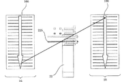
ここで、図1を用いて、従来の基板処理システムにおける基板搬送の制御内容を簡単に説明する。従来、図外の搬入部から未処理ワークを取り出した搬送ロボット22は、例えば、第1の処理チャンバ16の多段ラック166の最上段から処理済ワークを搬出し、その後、当該空となった段に未処理ワークを搬入する。その後、搬送ロボット22は、図外の搬出部まで処理済ワークを搬送する。続いて、搬送ロボット22は、再び搬入部から未処理ワークを取り出し、今度は第1の処理チャンバ16の多段ラック166の上から2番目の段から処理済ワークを搬出し、その後、当該空となった段に未処理ワークを搬入する。同様の動作を繰り返しつつ、搬送ロボット22は、まず第1の処理チャンバ16の多段ラックの最上段から最下段までの各段について処理済みワークの搬出処理および未処理ワークの搬入処理を行う。第1の処理チャンバ16の多段ラック166の最上段から最下段までの各段に対する処理済みワークの搬出処理および未処理ワークの搬入処理が完了した後に、上述と同様に第2の処理チャンバ18の多段ラック186の最上段から最下段までの各段について処理済みワークの搬出処理および未処理ワークの搬入処理を行う。
Here, with reference to FIG. 1, the contents of substrate transport control in the conventional substrate processing system will be briefly described. Conventionally, the
このような基板処理システムにおいては、基板に対する熱処理を行う際に、基板に塗布された昇華性成分(例えば、フォトレジストに含まれる昇華性成分)が気化し、この昇華物によって炉内の清浄度が低下することがあった。 In such a substrate processing system, when a heat treatment is performed on the substrate, a sublimable component (for example, a sublimable component contained in the photoresist) applied to the substrate is vaporized, and the sublimation product cleans the furnace. May decrease.
このため、従来、発生した昇華物をダクト等によって炉内から吸い出す排気システムについて様々な工夫がなされてきた。例えば、昇華ガスの濃度を下げるために、換気用空気を加熱して、ワークを通過する循環空気の上流部に導入するとともに、ワークを通過した空気の一部分を排出するように構成された熱処理装置が存在する(例えば、特許文献1参照。)。 For this reason, various contrivances have conventionally been made with respect to an exhaust system that sucks out generated sublimates from the furnace through a duct or the like. For example, in order to lower the concentration of the sublimation gas, the heat treatment apparatus is configured to heat the ventilation air and introduce it into the upstream portion of the circulating air passing through the work and to discharge a part of the air that has passed through the work. (For example, refer to Patent Document 1).
上述の特許文献1に係る熱処理装置を含む従来の熱処理装置においては、スループットを向上させようとすると、炉に対する基板の搬入時間間隔を可能な限り短くする必要が生じるが、基板の搬入時間間隔が短くなると昇華物ガスの濃度を低く抑えるために排気量を増加させる必要が生じる。 In the conventional heat treatment apparatus including the heat treatment apparatus according to Patent Document 1 described above, it is necessary to shorten the substrate loading time interval to the furnace as much as possible in order to improve the throughput. When it becomes shorter, it becomes necessary to increase the displacement in order to keep the concentration of the sublimate gas low.
そして、排気量の増加に伴って、排熱量または給気の加熱容量も増加することとなり、その結果、炉内を設定温度に保つために、ヒータからより多くの熱量を炉内に供給する必要が生じる。 As the amount of exhaust increases, the amount of exhaust heat or the heating capacity of the supply air also increases. As a result, in order to keep the inside of the furnace at a set temperature, it is necessary to supply a larger amount of heat from the heater. Occurs.
したがって、上述の特許文献1に係る熱処理装置を含む従来の熱処理装置では、スループットの向上に比例して電力消費の増加を余儀なくされるため、電力消費を削減するためにはスループットを犠牲にする必要があった。 Therefore, in the conventional heat treatment apparatus including the heat treatment apparatus according to Patent Document 1 described above, the power consumption must be increased in proportion to the improvement in the throughput. Therefore, it is necessary to sacrifice the throughput in order to reduce the power consumption. was there.
本発明の目的は、スループットを犠牲にすることなく、消費電力の削減を図ることが可能な基板処理システムおよび基板処理方法を提供することである。 An object of the present invention is to provide a substrate processing system and a substrate processing method capable of reducing power consumption without sacrificing throughput.
この発明に係る基板処理システムは、基板に対して熱処理を行うように構成される。基板の例としては、液晶ディスプレイやプラズマディスプレイ用のガラス基板や、半導体装置に用いられる半導体ウェハ等が挙げられる。 The substrate processing system according to the present invention is configured to perform a heat treatment on a substrate. Examples of the substrate include glass substrates for liquid crystal displays and plasma displays, and semiconductor wafers used for semiconductor devices.
この基板処理システムは、搬送部、複数の処理チャンバ、および制御部を備える。搬送部は、基板を搬送する搬送ロボットを備える。複数の処理チャンバは、それぞれ搬送部の周囲に配置される。各処理チャンバは、基板の搬入時および搬出時に開閉可能な扉を有する。 The substrate processing system includes a transfer unit, a plurality of processing chambers, and a control unit. The transport unit includes a transport robot that transports the substrate. The plurality of processing chambers are respectively arranged around the transfer unit. Each processing chamber has a door that can be opened and closed when the substrate is carried in and out.
制御部は、少なくとも搬送部および処理チャンバを制御する。制御部は、搬送ロボットが、同一の処理チャンバに連続してアクセスすることなく複数の処理チャンバに順次的にアクセスするように、搬送ロボットおよび扉の動作を制御する。 The control unit controls at least the transfer unit and the processing chamber. The control unit controls the operations of the transfer robot and the door so that the transfer robot sequentially accesses the plurality of process chambers without sequentially accessing the same process chamber.
この構成においては、タクト毎に異なる処理チャンバの扉の開閉動作が行われ、異なる処理チャンバに対して順番に基板が搬入または搬出される。このように、複数の処理チャンバへの基板投入順序を変更することにより、単一の処理チャンバ内における単位時間あたりの昇華物ガスの発生量が抑制され、炉内の昇華物ガスの濃度が減少する。 In this configuration, the opening / closing operation of the door of the different processing chamber is performed for each tact, and the substrates are sequentially carried into or out of the different processing chambers. In this way, by changing the order of loading substrates into a plurality of processing chambers, the amount of sublimation gas generated per unit time in a single processing chamber is suppressed, and the concentration of sublimation gas in the furnace is reduced. To do.
この結果、従来に比較して、排気量および給気量を絞った運転が可能となり、排気に伴う排熱の削減が可能となる。つまり、スループットを低下させることなく、省エネ運転が可能となる。また、炉内に付着した昇華物の除去等のメンテナンスの頻度の低減が可能となる。 As a result, it is possible to perform an operation with a reduced exhaust amount and an air supply amount as compared with the conventional case, and it is possible to reduce exhaust heat associated with the exhaust. That is, energy saving operation is possible without reducing the throughput. In addition, it is possible to reduce the frequency of maintenance such as the removal of sublimates attached to the furnace.
本発明によれば、スループットを犠牲にすることなく、大幅に消費電力の削減を図ることが可能になる。 According to the present invention, it is possible to significantly reduce power consumption without sacrificing throughput.
図2は、この発明の実施形態に係る基板処理システム10の概略を示している。この実施形態では、基板処理システム10は、カラーフィルタ製造工程を行うように構成されているが、本発明の適用範囲はカラーフィルタ製造工程には限定されない。
FIG. 2 schematically shows the
基板処理システム10は、搬入部12、搬出部14、搬送部15、第1の処理チャンバ16、および第2の処理チャンバ18を備える。搬入部12、搬出部14、および搬送部15は、透明部材で覆われたクリーンユニットの内部に配置される。
The
搬入部12は、未処理のワーク(基板)20の搬入口として機能するように構成される。この実施形態では、ワーク20は、長辺が約2.5メートルで短辺が約2、2メートルの長方形状のガラス基板であるが、熱処理システム10が処理するワーク20の種類はこれに限定されるものではない。搬出部14は、処理済みのワーク20を収容可能に構成される。
The carry-in
搬送部15は、熱処理システム10の中央部に位置しており、搬入部12、搬出部14、第1の処理チャンバ16、および第2の処理チャンバ18にそれぞれ隣接するように配置される。搬送部15は、内部に搬送ロボット22が設けられる。搬送ロボット22は、搬入部12、搬出部14、第1の処理チャンバ16、および第2の処理チャンバ18の間でワーク20の搬送を行うように構成される。第1の処理チャンバ16および第2の処理チャンバ18は、搬入されたワーク20に対して熱処理を行うように構成される。
The
図3は、第1の処理チャンバ16、第2の処理チャンバ18、および搬送ロボット22の概略構成を示している。第1の処理チャンバ16は、ワーク20が搬入および搬出される開口部を有する炉体164と、開口部を選択的に遮断する扉162とを備える。
FIG. 3 shows a schematic configuration of the
炉体164は、各段にワーク20を支持可能に構成された多段ラック166を備える。扉162は、それぞれが垂直方向に伸びる軸に沿って昇降可能に支持された複数のシャッタ片から構成される。各シャッタ片は、互いに連携して昇降するように構成されており、例えば、隣り合う2つのシャッタ片を離間または接触させることにより、多段ラック166の所望の段に対してワーク20の搬入および搬出が可能になる。
The
第2の処理チャンバ18は、第1の処理チャンバ16と同様に、炉体184、扉182、および多段ラック186を少なくとも備える。これらの構成は、第1の処理チャンバ16のものと実質的に同一であるため、ここでは説明を省略する。
Similar to the
搬送ロボット22は、ワーク20を支持可能に構成されたハンド225を備える。搬送ロボット22は、ハンド225を昇降および回転させることにより多段ラック166および多段ラック186の任意の段に対してワーク20を搬入および搬出できるように構成されている。
The
図4は、基板処理システム10の概略を示すブロック図である。図4に示すように、第1の処理チャンバ16は、扉駆動部169、換気部168、熱処理部167、および制御部165を少なくとも備える。扉駆動部169は、上述の扉166の開閉動作を行うように構成される。換気部168は、炉体164に外気を導入する導入部および炉体164内部のガスの排気を行う排気部を有する。換気部168は、チャンバ内の昇華物ガスの濃度に合わせた排気量および給気量が設定される。熱処理部167は、炉体164を設定された温度(例えば、230℃)で加熱し、炉体164に搬入されたワーク20に対して熱処理を行うように構成される。制御部165は、メイン制御部30から供給される制御情報に基づいて第1の処理チャンバ16の各部の動作を制御するように構成される。
FIG. 4 is a block diagram showing an outline of the
第2の処理チャンバ18は、扉駆動部189、換気部188、熱処理部187、および制御部185を少なくとも備える。これらの構成は、上述の扉駆動部169、換気部168、熱処理部167、および制御部165と同様であるため、ここでは説明を省略する。
The
搬送ロボット22は、移動機構部226、ハンド駆動部224、および制御部222を備える。移動機構部226は、搬送ロボット22の水平方向に移動させる機構、および搬送ロボット22を回転運動させる機構を少なくとも備える。ハンド駆動部224は、ハンド225の昇降動作、水平方向の移動、動作回転、およびワーク20の把持/把持解除を行うように構成される。制御部222は、メイン制御部30からの制御情報に基づいて、搬送ロボット22の各部の動作を制御するように構成される。
The
図5は、メイン制御部30による制御内容を説明するための図である。この実施形態に係る基板処理システム10では、メイン制御部30が、第1の処理チャンバ16または第2の処理チャンバ18へ交互に搬送ロボット22をアクセスさせている。よって、ここでは、図1のように、第1の処理チャンバ16の多段ラック166の最上段から最下段までの各段に対する処理済みのワーク20の搬出処理および未処理のワーク20の搬入処理が完了した後に、第2の処理チャンバ18の多段ラック186の最上段から最下段までの各段について処理済みのワーク20の搬出処理および未処理のワーク20の搬入処理を行うのではなく、第1の処理チャンバ16に対する処理済みのワーク20の搬出処理および未処理のワーク20の搬入処理と、第2の処理チャンバ18に対する処理済みのワーク20の搬出処理および未処理のワーク20の搬入処理と、が順次行われる。
FIG. 5 is a diagram for explaining the contents of control by the
具体的には、メイン制御部30は、搬送ロボット22に搬入部12の未処理のワーク20を取り出させる。次に、メイン制御部30は、搬入すべき位置および順番に関する記憶情報に基づいて第1の処理チャンバ16の扉162を開放し、その後、搬送ロボット22の動作を制御することにより、多段ラック166の対応する段から処理済みのワーク20を搬出し、空段となった同じ段に未処理ワーク20を搬入させる。ここで、処理済みのワーク20とは、第1の処理チャンバ内に搬入された後に熱処理に必要な所定時間が経過したワーク20を意味する。
Specifically, the
その後、メイン制御部30は、搬送ロボット22に搬出部14へ処理済みのワーク20を排出させて、搬送ロボット22を搬入部12の前まで移動させ、搬入部12の未処理ワーク20を取り出させる。
Thereafter, the
続いて、メイン制御部30は、搬入すべき位置および順番に関する記憶情報に基づいて第2の処理チャンバ18の扉182を開放し、その後、搬送ロボット22の動作を制御することにより、多段ラック186の対応する段から処理済みのワーク20を搬出し、空段となった同じ段に未処理ワーク20を搬入させる。
Subsequently, the
その後、メイン制御部30は、搬送ロボット22に搬出部14へ処理済みのワーク20を排出させて、搬送ロボット22を搬入部12の前まで移動させ、搬入部12の未処理ワーク20を取り出させる。
Thereafter, the
以後も第1の処理チャンバ16および第2の処理チャンバ18に対してこのような動作を順次継続することにより、第1の処理チャンバ16および第2の処理チャンバ18内の多段ラック166、186に支持されたすべてのワーク20に対して所定時間の熱処理が行われるように搬送ロボット22および扉162、182の動作を制御する。
Thereafter, such operations are successively performed on the
ここでは、多段ラック166の最上段→多段ラック186の最上段→多段ラック166の上から2段目→多段ラック186の上から2段目→…→多段ラック166の最下段→多段ラック186の最下段の順に搬送ロボット22がアクセスする例を示しているが、アクセス順はこの例に限定されることはない。
Here, the uppermost stage of the
図6は、6つの処理チャンバ17を備える基板処理システム11の概略構成を示している。基板処理システム11は、搬入部12、搬出部14、および搬送部150と、6つの処理チャンバ17とを備える。基板処理システム11は、処理チャンバ17の数が6つである点を除くと、その基本的な構成は、基板処理システム10と同様である。
FIG. 6 shows a schematic configuration of the substrate processing system 11 including six
基板処理システム11においても、搬送ロボット22は、6つの処理チャンバ17に順次的にアクセスし、同一の処理チャンバ17に対して連続してアクセスすることがないように制御されている。
Also in the substrate processing system 11, the
ここでも、メイン制御部30は、搬入すべき位置および順番に関する記憶情報に基づいて、6つの処理チャンバ17のうちの1つに対して、処理済みのワーク20を搬出する処理、および空段となった同じ段に未処理のワーク20を搬入する処理を行う。その後、メイン制御部30は、搬送ロボット22に搬出部14へ処理済みのワーク20を排出させて、搬送ロボット22を搬入部12の前まで移動させ、搬入部12の未処理ワーク20を取り出させる。そして、6つの処理チャンバ17のうちの次の1つに対して、同様の動作を行う。以後も6つの処理チャンバ17に対してこのような動作を順次継続することにより、6つの処理チャンバ17内の多段ラックに支持されたすべてのワーク20に対して所定時間の熱処理が行われるように搬送ロボット22および扉162、182の動作を制御する。
Also here, the
上述のように、処理チャンバが2台の場合には、第1の処理チャンバに対して処理済みのワーク20の搬出および未処理のワーク20の搬入という一対の操作を行い、その後第2の処理チャンバに同様の1対の操作を行い、以後も第1の処理チャンバおよび第2の処理チャンバを交互にこの操作を繰り返す。また、基板処理システムに6台の処理チャンバが設けられる場合は、第1〜第6の処理チャンバの順で上述の1対の操作を行い、以後も同様の操作を行う。
As described above, when there are two processing chambers, a pair of operations of carrying out the processed
これを一般化して処理チャンバがn台の場合を説明すると、メイン制御部30は、第1の処理チャンバに対して処理済みのワーク20の搬出および未処理のワーク20の搬入という一対の操作を行い、続いて、第2の処理チャンバに対して同様の操作を行い、第n−1の処理チャンバに対して同様の操作を行い、そして、第nの処理チャンバに対して同様の処理を行い、再度、第1の処理チャンバに対して同様の操作を行い、以後、このような操作を順次継続することになる。この結果、処理チャンバの数にかかわらず、すべてのワーク20についてチャンバ内滞在時間を同じにできる。
Generalizing this and explaining the case where there are n processing chambers, the
一般的には、基板処理システム内の処理チャンバの数が増加すると、排気量およびヒータ容量の低減をより図ることが可能になる。例えば、図2に示す基板処理システム10よりも図6に示す基板処理システム11の方がさらに、排気量およびヒータ容量の低減を図ることが可能になる。
In general, as the number of processing chambers in the substrate processing system increases, the exhaust amount and the heater capacity can be further reduced. For example, the substrate processing system 11 shown in FIG. 6 can further reduce the displacement and the heater capacity than the
例えば、図6に示すように、複数の処理チャンバを設置した基板処理システム11において、ワーク20の投入順序を振り分けることにより、単位時間当たりの最大投入枚数を平均化することが可能になり、単一の処理チャンバ17における単位時間あたりの昇華物ガスの発生量を抑制することが可能になる。また、その結果、ヒータ容量の削減を図ることができ、また、ランニングコストの削減を図ることが可能になる。さらに、処理チャンバ17内に昇華物が付着することが防止し易くなるため、処理チャンバ17のメンテナンス性が向上する。
For example, as shown in FIG. 6, in the substrate processing system 11 in which a plurality of processing chambers are installed, it is possible to average the maximum number of input sheets per unit time by distributing the input order of the
図7は、n個の処理チャンバを有する基板処理システム10の効果の概要を示している。ここでは、基板処理システム10全体としてのスループットが従来の基板処理システムと同一であるという前提で説明を行う。同図に示すように、基板処理システム10では、第1〜第nの処理チャンバのそれぞれについて、ワーク20の投入時間間隔をn倍(nは、システムに設けられる処理チャンバ数)に拡げることが可能になる。この結果、理論的には、ワーク20の投入に伴って発生する昇華ガスの発生量を1/nに抑えることが可能になる。そして、第1〜第nの各処理チャンバをそれぞれ許容される清浄度に保つために必要となる換気量、つまり排気量についても、理論的には、1/nに抑えることが可能になる。よって、換気部168および換気部188の構成を簡略化することが可能となり、また、換気部168および換気部188において消費される電力量を低減することが可能になる。
FIG. 7 shows an overview of the effects of the
故に、第1〜第nの各処理チャンバ内を設定温度に保つために必要なヒータ容量も理論的に1/nに抑えることが可能になるため、基板処理システム10における電力消費量を大幅に削減することが可能になる。
Therefore, the heater capacity necessary for keeping the first to n-th processing chambers at the set temperature can be theoretically suppressed to 1 / n, so that the power consumption in the
例えば、第1の処理チャンバ16または第2の処理チャンバ18を有する基板処理システム10においては、従来基板搬入時間間隔が60秒であるところを120秒まで拡げると、昇華物ガスの発生量を30ppmから15ppmまで低減する。このため、チャンバ内の汚染度を従来と同一基準として運転する場合には、排気量を40m3 /分から20m3 /分にまで低減可能となるので、排気分熱量を補うためのヒータ容量を90kwから45kwに低減することが理論上可能となる。すなわち、スループットを減じることなく消費電力量を従来の半分程度に抑えることが理論上可能となる。
For example, in the
さらに、上述の実施形態で説明した動作以外にも、本発明に係る基板処理システムでは、搬送ロボット22のアームやハンドの構成次第で多様な運転が可能である。例えば、上述の実施形態では、搬送ロボット22が処理済みのワーク20を処理チャンバから取り出すと同時に、把持している未処理のワーク20を処理チャンバに搬入する動作を行っているが、一度に単一のワーク20しか把持できない搬送ロボットを用いる際には、処理済みのワーク20の搬出→搬出部14への移動→搬入部12への移動→未処理のワーク20の搬入という流れで搬送ロボット22を動作させると良い。また、この場合、搬送ロボット22が処理チャンバから離れている間は処理チャンバの扉を閉じておくことが好ましい。
Furthermore, in addition to the operations described in the above embodiments, the substrate processing system according to the present invention can perform various operations depending on the configuration of the arm and hand of the
また、上述の実施形態では、搬送ロボット22が処理チャンバに1枚ずつワーク20を出し入れする場合について説明したが、搬送ロボット22が処理チャンバに対して一度に複数枚(例えば、直近の2枚)のワーク20を出し入れするようにしても良い。
In the above-described embodiment, the case where the
なお、本発明の基板処理システムに用いられる処理チャンバの構成は上述した構成に限定されるものではない。例えば、図8に示すように、回動可能な小扉40を各段ごとに対応させて設けるとともに、各小扉40をシリンダ駆動によって開閉させるように構成された処理チャンバを本発明の基板処理システムに適用することも可能である。
The configuration of the processing chamber used in the substrate processing system of the present invention is not limited to the configuration described above. For example, as shown in FIG. 8, a pivotable
上述の実施形態では、基板処理システム(10、11)に設けられた処理チャンバの数が2個または6個の場合を説明したが、処理チャンバの数は2個以上であれば良く、上述の例には限定されない。 In the above-described embodiment, the case where the number of processing chambers provided in the substrate processing system (10, 11) is two or six has been described, but the number of processing chambers may be two or more. It is not limited to examples.
上述の実施形態の説明は、すべての点で例示であって、制限的なものではないと考えられるべきである。本発明の範囲は、上述の実施形態ではなく、特許請求の範囲によって示される。さらに、本発明の範囲には、特許請求の範囲と均等の意味および範囲内でのすべての変更が含まれることが意図される。 The above description of the embodiment is to be considered in all respects as illustrative and not restrictive. The scope of the present invention is shown not by the above embodiments but by the claims. Furthermore, the scope of the present invention is intended to include all modifications within the meaning and scope equivalent to the scope of the claims.
10−基板処理システム
12−搬入部
14−搬出部
15−搬送部
16−第1の処理チャンバ
18−第2の処理チャンバ
22−搬送ロボット
30−メイン制御部
DESCRIPTION OF SYMBOLS 10- Substrate processing system 12- Loading part 14- Unloading part 15- Transfer part 16- 1st processing chamber 18- 2nd processing chamber 22- Transfer robot 30- Main control part
Claims (2)
基板を搬送する搬送ロボットと、
前記処理チャンバおよび搬送ロボットを制御する制御部と、を備え、基板に対して熱処理を行うように構成された基板処理システムであって、
前記処理チャンバは、各段に基板を支持可能とされた多段ラックと、基板の搬入時および搬出時に多段ラックの所望の段に対応して開閉可能な扉を有し、
前記制御部は、一の処理チャンバ内に搬入された後に所定時間が経過した基板を当該一の処理チャンバから搬出し、続いて当該一の処理チャンバ内に未処理の基板を搬入した後、他の一の処理チャンバ内に搬入された後に所定時間が経過した基板を当該他の一の処理チャンバから搬出し、続いて当該他の一の処理チャンバ内に未処理の基板を搬入し、以後も前記複数の処理チャンバに対してこのような動作を順次継続することにより、前記複数の処理チャンバ内の多段ラックに支持されたすべての基板に対して所定時間の熱処理が行われるように前記搬送ロボットおよび前記扉の動作を制御する基板処理システム。 A plurality of processing chambers configured to heat-treat the substrate;
A transfer robot for transferring substrates;
A substrate processing system comprising a controller for controlling the processing chamber and the transfer robot, and configured to perform heat treatment on the substrate,
The processing chamber has a multi-stage rack capable of supporting a substrate on each stage, and a door that can be opened and closed corresponding to a desired stage of the multi-stage rack when the substrate is carried in and out.
The control unit unloads a substrate that has passed a predetermined time after being loaded into one processing chamber from the one processing chamber, and then loads an unprocessed substrate into the one processing chamber. A substrate that has passed a predetermined time after being loaded into one processing chamber is unloaded from the other processing chamber, and an untreated substrate is loaded into the other processing chamber. The transfer robot is configured so that heat treatment for a predetermined time is performed on all the substrates supported by the multistage racks in the plurality of processing chambers by sequentially continuing such operations on the plurality of processing chambers. And a substrate processing system for controlling the operation of the door.
基板を搬送する搬送ロボットと、を備え、基板に対して熱処理を行うように構成された基板処理システムに適用される基板処理方法であって、
前記搬送ロボットが、一の処理チャンバ内に搬入された後に所定時間が経過した基板を当該処理チャンバから搬出し、続いて当該処理チャンバ内に未処理の基板を搬入した後、他の一の処理チャンバ内に搬入された後に所定時間が経過した基板を当該他の一の処理チャンバから搬出し、続いて当該他の処理チャンバ内に未処理の基板を搬入し、
以後も前記複数の処理チャンバに対してこのような動作を順次継続することにより、前記複数の処理チャンバ内の多段ラックに支持されたすべての基板に対して所定時間の熱処理を行う基板処理方法。 A multi-stage rack capable of supporting a substrate on each stage, and a plurality of processing chambers having doors that can be opened and closed corresponding to a desired stage of the multi-stage rack at the time of loading and unloading the substrate;
A substrate processing method that is applied to a substrate processing system configured to perform a heat treatment on a substrate,
The transfer robot unloads a substrate that has passed a predetermined time after being loaded into one processing chamber from the processing chamber, and then loads an unprocessed substrate into the processing chamber. A substrate that has passed a predetermined time after being loaded into the chamber is unloaded from the other processing chamber, and then an unprocessed substrate is loaded into the other processing chamber.
Thereafter, a substrate processing method for performing a heat treatment for a predetermined time on all the substrates supported by the multi-stage rack in the plurality of processing chambers by sequentially continuing such operations for the plurality of processing chambers.
Priority Applications (5)
| Application Number | Priority Date | Filing Date | Title |
|---|---|---|---|
| JP2009065793A JP5280901B2 (en) | 2009-03-18 | 2009-03-18 | Substrate processing system and substrate processing method |
| TW99106575A TWI471966B (en) | 2009-03-18 | 2010-03-08 | Substrate processing system and substrate processing method |
| TW103146534A TWI524460B (en) | 2009-03-18 | 2010-03-08 | Substrate processing system |
| CN201310302882.2A CN103438710B (en) | 2009-03-18 | 2010-03-09 | Substrate processing system |
| CN 201010132170 CN101839644B (en) | 2009-03-18 | 2010-03-09 | Substrate processing system and substrate processing method |
Applications Claiming Priority (1)
| Application Number | Priority Date | Filing Date | Title |
|---|---|---|---|
| JP2009065793A JP5280901B2 (en) | 2009-03-18 | 2009-03-18 | Substrate processing system and substrate processing method |
Related Child Applications (1)
| Application Number | Title | Priority Date | Filing Date |
|---|---|---|---|
| JP2013108883A Division JP5355808B2 (en) | 2013-05-23 | 2013-05-23 | Substrate processing system |
Publications (2)
| Publication Number | Publication Date |
|---|---|
| JP2010219383A JP2010219383A (en) | 2010-09-30 |
| JP5280901B2 true JP5280901B2 (en) | 2013-09-04 |
Family
ID=42743177
Family Applications (1)
| Application Number | Title | Priority Date | Filing Date |
|---|---|---|---|
| JP2009065793A Expired - Fee Related JP5280901B2 (en) | 2009-03-18 | 2009-03-18 | Substrate processing system and substrate processing method |
Country Status (3)
| Country | Link |
|---|---|
| JP (1) | JP5280901B2 (en) |
| CN (2) | CN101839644B (en) |
| TW (2) | TWI471966B (en) |
Families Citing this family (3)
| Publication number | Priority date | Publication date | Assignee | Title |
|---|---|---|---|---|
| JP2012212746A (en) * | 2011-03-31 | 2012-11-01 | Tokyo Electron Ltd | Substrate transfer device and substrate transfer method |
| JP7023094B2 (en) * | 2017-12-05 | 2022-02-21 | 日本電産サンキョー株式会社 | robot |
| JP7149748B2 (en) * | 2018-07-04 | 2022-10-07 | 東京エレクトロン株式会社 | SUBSTRATE PROCESSING SYSTEM, SUBSTRATE TRANSFER METHOD, AND CONTROL PROGRAM |
Family Cites Families (11)
| Publication number | Priority date | Publication date | Assignee | Title |
|---|---|---|---|---|
| JP3959141B2 (en) * | 1996-11-12 | 2007-08-15 | エスペック株式会社 | Heat treatment equipment with sublimation countermeasures |
| JP3462405B2 (en) * | 1998-10-29 | 2003-11-05 | 東京エレクトロン株式会社 | Processing equipment |
| JP3648589B2 (en) * | 1998-12-01 | 2005-05-18 | 光洋サーモシステム株式会社 | Heat treatment equipment |
| JP3582820B2 (en) * | 2000-03-24 | 2004-10-27 | 東京エレクトロン株式会社 | Processing system and interface device |
| JP4201502B2 (en) * | 2000-10-11 | 2008-12-24 | 独立行政法人産業技術総合研究所 | Electrostatic chuck and manufacturing method thereof |
| JP5034138B2 (en) * | 2001-01-25 | 2012-09-26 | 東京エレクトロン株式会社 | Heat treatment method and heat treatment apparatus |
| JP2002368030A (en) * | 2001-06-08 | 2002-12-20 | Hitachi Ltd | Resin-sealed semiconductor device and method of manufacturing the same |
| JP2003294373A (en) * | 2002-03-29 | 2003-10-15 | Espec Corp | Article heat treatment device and device having housing part |
| JP4047826B2 (en) * | 2004-03-25 | 2008-02-13 | 東京エレクトロン株式会社 | Vertical heat treatment apparatus and automatic teaching method for transfer mechanism |
| TW200711029A (en) * | 2005-08-05 | 2007-03-16 | Tokyo Electron Ltd | Substrate processing apparatus and substrate stage used therein |
| JP5318327B2 (en) * | 2006-02-08 | 2013-10-16 | 光洋サーモシステム株式会社 | Heat treatment equipment |
-
2009
- 2009-03-18 JP JP2009065793A patent/JP5280901B2/en not_active Expired - Fee Related
-
2010
- 2010-03-08 TW TW99106575A patent/TWI471966B/en active
- 2010-03-08 TW TW103146534A patent/TWI524460B/en not_active IP Right Cessation
- 2010-03-09 CN CN 201010132170 patent/CN101839644B/en active Active
- 2010-03-09 CN CN201310302882.2A patent/CN103438710B/en not_active Expired - Fee Related
Also Published As
| Publication number | Publication date |
|---|---|
| CN103438710B (en) | 2015-06-24 |
| TW201041074A (en) | 2010-11-16 |
| TWI471966B (en) | 2015-02-01 |
| JP2010219383A (en) | 2010-09-30 |
| CN101839644A (en) | 2010-09-22 |
| CN101839644B (en) | 2013-07-31 |
| TWI524460B (en) | 2016-03-01 |
| TW201521145A (en) | 2015-06-01 |
| CN103438710A (en) | 2013-12-11 |
Similar Documents
| Publication | Publication Date | Title |
|---|---|---|
| KR100233310B1 (en) | Heat treating apparatus | |
| US6331095B1 (en) | Transportation system and processing apparatus employing the transportation system | |
| KR20110128149A (en) | Substrate processing apparatus and substrate processing method | |
| WO2006043509A1 (en) | Vertical heat treatment apparatus and method for operating same | |
| JP3908468B2 (en) | High efficiency cooling heat treatment equipment | |
| JP5280901B2 (en) | Substrate processing system and substrate processing method | |
| KR102452122B1 (en) | Substrate processing apparatus, method of manufacturing semiconductor device and computer program | |
| JP5355808B2 (en) | Substrate processing system | |
| JP2012028087A (en) | Ion supply device and processing system for workpiece equipped with the same | |
| JP2006093188A (en) | Deposition system and deposition method | |
| JP2004304003A (en) | Processing system | |
| JP2009065068A (en) | Substrate treating apparatus, contamination suppressing method for substrate treating apparatus, and storage medium | |
| JP2014120520A (en) | Substrate processing device, substrate processing method and storage medium | |
| TWI763945B (en) | Substrate processing device, manufacturing method of semiconductor device, and computer program product | |
| KR102198676B1 (en) | Film forming device | |
| JP3862197B2 (en) | Vertical heat treatment equipment | |
| JP2020145329A (en) | Substrate storage device | |
| JP2003077398A (en) | Manufacturing method of plasma display panel and furnace equipment for same | |
| JP6241777B2 (en) | Substrate processing apparatus and substrate processing method | |
| JP2004037077A (en) | Multi-chamber heat treatment furnace | |
| JP5872880B2 (en) | Substrate processing apparatus, substrate transfer apparatus, and semiconductor device manufacturing method | |
| JP2000161858A (en) | Method and system for heat treating glass substrate | |
| JP2012078005A (en) | Continuous heat treatment furnace | |
| JP2010283178A (en) | Semiconductor manufacturing apparatus and method | |
| JPH0230120A (en) | Treatment device |
Legal Events
| Date | Code | Title | Description |
|---|---|---|---|
| A621 | Written request for application examination |
Free format text: JAPANESE INTERMEDIATE CODE: A621 Effective date: 20120201 |
|
| A977 | Report on retrieval |
Free format text: JAPANESE INTERMEDIATE CODE: A971007 Effective date: 20130412 |
|
| TRDD | Decision of grant or rejection written | ||
| A01 | Written decision to grant a patent or to grant a registration (utility model) |
Free format text: JAPANESE INTERMEDIATE CODE: A01 Effective date: 20130423 |
|
| A61 | First payment of annual fees (during grant procedure) |
Free format text: JAPANESE INTERMEDIATE CODE: A61 Effective date: 20130523 |
|
| R150 | Certificate of patent or registration of utility model |
Free format text: JAPANESE INTERMEDIATE CODE: R150 Ref document number: 5280901 Country of ref document: JP Free format text: JAPANESE INTERMEDIATE CODE: R150 |
|
| R250 | Receipt of annual fees |
Free format text: JAPANESE INTERMEDIATE CODE: R250 |
|
| R250 | Receipt of annual fees |
Free format text: JAPANESE INTERMEDIATE CODE: R250 |
|
| R250 | Receipt of annual fees |
Free format text: JAPANESE INTERMEDIATE CODE: R250 |
|
| R250 | Receipt of annual fees |
Free format text: JAPANESE INTERMEDIATE CODE: R250 |
|
| R250 | Receipt of annual fees |
Free format text: JAPANESE INTERMEDIATE CODE: R250 |
|
| R250 | Receipt of annual fees |
Free format text: JAPANESE INTERMEDIATE CODE: R250 |
|
| LAPS | Cancellation because of no payment of annual fees |