JP5272569B2 - Chatter simulation apparatus and chatter simulation method - Google Patents
Chatter simulation apparatus and chatter simulation method Download PDFInfo
- Publication number
- JP5272569B2 JP5272569B2 JP2008205651A JP2008205651A JP5272569B2 JP 5272569 B2 JP5272569 B2 JP 5272569B2 JP 2008205651 A JP2008205651 A JP 2008205651A JP 2008205651 A JP2008205651 A JP 2008205651A JP 5272569 B2 JP5272569 B2 JP 5272569B2
- Authority
- JP
- Japan
- Prior art keywords
- workpiece
- grindstone
- shape
- chatter
- grinding
- Prior art date
- Legal status (The legal status is an assumption and is not a legal conclusion. Google has not performed a legal analysis and makes no representation as to the accuracy of the status listed.)
- Expired - Fee Related
Links
Images


Abstract
Description
研削加工において、工作物のびびり現象をシミュレーションするびびりシミュレーション装置、および、びびりシミュレーション方法に関するものである。 The present invention relates to a chatter simulation apparatus and a chatter simulation method for simulating a chatter phenomenon of a workpiece in grinding.
研削加工は、例えば、高速に回転する砥石と、回転する工作物とを接触させて行われる。このような研削加工おいては、研削加工中にびびり現象が生じることが多い。研削加工中、びびり現象が起こると、研削加工後の工作物に周期性のある平行なすじ等(以下、「びびり」と称する)が残ってしまう。その結果、製品の品質が低下してしまう問題があった。 The grinding process is performed, for example, by bringing a grindstone that rotates at a high speed into contact with a rotating workpiece. In such a grinding process, chattering often occurs during the grinding process. When chattering occurs during grinding, parallel streaks with periodicity (hereinafter referred to as “chatter”) remain in the workpiece after grinding. As a result, there is a problem that the quality of the product is deteriorated.
従来、この問題に対して、作業者の経験や勘等により、研削加工条件を変更して解消を図っていた。つまり、研削加工を実施した後、その加工面状態を確認し、そこでびびりが有ることを発見した場合、研削加工条件を変更し、再度研削加工を行い、加工面状態を確認する。このため、多大な作業量および作業時間が必要であった。 Conventionally, this problem has been solved by changing the grinding conditions based on the experience and intuition of the operator. That is, after carrying out the grinding process, the state of the machined surface is confirmed. If it is found that there is chatter, the grinding condition is changed, the grinding process is performed again, and the machined surface state is confirmed. For this reason, a great amount of work and work time are required.
そこで、特開平8−174379号公報(特許文献1)に記載されたびびり振動抑制方法では、びびり現象の抑制作業を自動的に行うことができることとなっている。これによれば、びびり抑制作業の自動化を行うことができる。
しかしながら、上記方法では、工作機械の振動を、研削加工中に実際に測定しながら研削加工を行わなければならない。つまり、実際に研削加工を行わなければ、びびりを検知することができず、測定不良等が発生すると、研削加工中の工作物の製品品質を著しく低下させる虞がある。 However, in the above method, the grinding must be performed while actually measuring the vibration of the machine tool during the grinding. That is, if grinding is not actually performed, chatter cannot be detected, and if a measurement failure occurs, the product quality of the workpiece being ground may be significantly reduced.
また、上記方法では、研削加工中に起きた実際のびびりに対する対応であるため、びびりに対する研削加工が後手に回り、生産効率の面でも問題がある。そこで、研削加工において、びびり現象をシミュレーションしたいという要望がある。 In addition, since the method described above is a response to the actual chatter that occurred during the grinding process, the grinding process for chatter is delayed and there is a problem in terms of production efficiency. Therefore, there is a demand for simulation of chatter phenomenon in grinding.
本発明は、このような事情に鑑みてなされたものであり、研削加工におけるびびり現象をより正確にシミュレーションできるびびりシミュレーション装置、および、びびりシミュレーション方法を提供することを目的とする。 The present invention has been made in view of such circumstances, and an object thereof is to provide a chatter simulation apparatus and a chatter simulation method capable of more accurately simulating chatter phenomena in grinding.
本発明のびびりシミュレーション装置は、回転駆動される工作物に、回転駆動される砥石を接触させて、工作物を研削する研削加工において、工作物のびびり現象をシミュレーションするびびりシミュレーション装置であって、工作物形状記憶部と、砥石形状記憶部と、指令値記憶部と、相対位置算出部と、除去量算出部と、工作物形状変更部と、研削抵抗算出部と、変位量算出部と、変位量補正部と、びびり判定部とを備えることを特徴とする。 The chatter simulation apparatus of the present invention is a chatter simulation apparatus for simulating the chatter phenomenon of a workpiece in a grinding process in which a grindstone to be rotated is brought into contact with a rotationally driven workpiece and the workpiece is ground. Workpiece shape storage unit, grinding wheel shape storage unit, command value storage unit, relative position calculation unit, removal amount calculation unit, workpiece shape change unit, grinding resistance calculation unit, displacement amount calculation unit, A displacement amount correction unit and a chatter determination unit are provided.
工作物形状記憶部は、工作物の形状を記憶する。砥石形状記憶部は、砥石の形状を記憶する。指令値記憶部は、研削加工における研削盤に対する指令値を記憶する。相対位置算出部は、指令値に基づいて、前記砥石が前記工作物に対して相対移動する方向である砥石移動方向における工作物と砥石との所定時間毎の相対位置を順に算出する。砥石移動方向は、通常、X軸方向またはZ軸方向である。 The workpiece shape storage unit stores the shape of the workpiece. The grindstone shape storage unit stores the shape of the grindstone. The command value storage unit stores a command value for the grinding machine in grinding. The relative position calculation unit sequentially calculates the relative position of the workpiece and the grindstone at predetermined time intervals in the grindstone moving direction, which is the direction in which the grindstone moves relative to the workpiece, based on the command value. The grindstone moving direction is usually the X-axis direction or the Z-axis direction.
除去量算出部は、相対位置が算出される毎に、工作物形状記憶部に記憶されている工作物の形状、砥石形状記憶部に記憶されている砥石の形状、および、相対位置に基づいて、砥石による工作物の除去量を算出する。工作物形状変更部は、除去量が算出される毎に、工作物形状記憶部に記憶されている工作物の形状を除去量に基づいて変更する。 Removing amount calculating unit, for each relative position is calculated, the shape of the workpiece shape storage unit stored in Tei Ru workpiece, Tei Ru grindstone shape is stored in the grindstone shape storage unit, and, based on the relative position Then, the removal amount of the workpiece by the grindstone is calculated. Workpiece shape changing unit, every time removal amount is calculated, to change based on the amount of removing the shape of the workpiece stored in a workpiece shape storage unit.
研削抵抗算出部は、除去量が算出される毎に、研削加工における砥石移動方向の研削抵抗を除去量に基づいて算出する。変位量算出部は、研削抵抗が算出される毎に、研削抵抗に起因して砥石と工作物とが砥石移動方向に相対変位する変位量を算出する。変位量補正部は、変位量が算出される毎に、相対位置算出部において次回算出される砥石移動方向の相対位置を変位量に基づいて補正する。びびり判定部は、工作物形状記憶部に記憶されている、工作物形状変更部により2回以上変更された工作物の形状に基づいて、びびりの有無を判定する。 Each time the removal amount is calculated , the grinding resistance calculation unit calculates the grinding resistance in the grinding wheel moving direction in the grinding process based on the removal amount . Each time the grinding resistance is calculated , the displacement amount calculation unit calculates a displacement amount by which the grindstone and the workpiece are relatively displaced in the grindstone moving direction due to the grinding resistance. Displacement correction unit, for each displacement amount is calculated, is corrected based on the relative position of the grinding wheel moving direction calculated next time have contact to the relative position calculation unit to a displacement amount. The chatter determining unit determines the presence or absence of chatter based on the shape of the workpiece that has been changed twice or more by the workpiece shape changing unit stored in the workpiece shape storage unit.
すなわち、本発明のびびりシミュレーション装置では、研削抵抗がびびり現象の主要因であると考えている。つまり、研削抵抗に起因する砥石と工作物との相対変位量を算出して、この相対変位量を考慮した工作物形状をシミュレーションし、それを基にびびりの有無を判定している。従って、より正確にびびり現象をシミュレーションできる。びびりの有無は、工作物の研削加工面の面粗さによって判定できる。 That is, in the chatter simulation apparatus of the present invention, the grinding resistance is considered to be the main factor of the chatter phenomenon. That is, the relative displacement amount between the grindstone and the workpiece caused by the grinding resistance is calculated, the workpiece shape is simulated in consideration of the relative displacement amount, and the presence or absence of chatter is determined based on the simulation. Therefore, the chatter phenomenon can be simulated more accurately. The presence or absence of chatter can be determined by the surface roughness of the ground surface of the workpiece.
仮に、研削抵抗が大きいとしても、工作物剛性および砥石剛性が大きい場合には、研削抵抗に起因する相対変位量はほとんどゼロとなる。つまり、相対変位量は、工作物剛性および砥石剛性によって異なる。ここで、工作物剛性とは、研削盤に支持された状態の工作物に対して砥石移動方向の力を与えた場合における工作物の砥石移動方向の変位量に応じたものである。例えば、工作物剛性は、当該工作物の砥石移動方向の変位量の逆数などである。砥石剛性とは、研削盤に支持された状態の砥石に対して砥石移動方向の力を与えた場合における砥石の砥石移動方向の変位量に応じたものである。例えば、砥石剛性は、当該砥石の砥石移動方向の変位量の逆数などである。 Even if the grinding resistance is large, if the workpiece rigidity and the grinding wheel rigidity are large, the relative displacement due to the grinding resistance is almost zero. That is, the relative displacement amount varies depending on the workpiece rigidity and the grindstone rigidity. Here, the workpiece rigidity corresponds to the amount of displacement of the workpiece in the grinding wheel movement direction when a force in the grinding wheel movement direction is applied to the workpiece supported by the grinding machine. For example, the workpiece rigidity is the reciprocal of the amount of displacement of the workpiece in the moving direction of the grindstone. The grindstone rigidity corresponds to the amount of displacement of the grindstone in the grindstone moving direction when a force in the grindstone moving direction is applied to the grindstone supported by the grinder. For example, the grindstone rigidity is the reciprocal of the displacement amount of the grindstone in the grindstone moving direction.
一般に、工作物剛性は砥石剛性よりも低いため、相対変位量は、工作物剛性が主として影響を及ぼす。そこで、本発明のびびりシミュレーション装置は、さらに、研削盤に支持された状態の工作物に対して砥石移動方向の力を与えた場合における工作物の砥石移動方向の変位量に応じた工作物剛性を記憶する剛性記憶部を備え、変位量算出部は、その工作物剛性に基づいて変位量を算出することが好ましい。これにより、より高精度な変位量を算出することができる。 In general, since the workpiece rigidity is lower than the grindstone rigidity, the relative rigidity is mainly influenced by the workpiece rigidity. Therefore, the chatter simulation apparatus according to the present invention further provides a workpiece rigidity according to the amount of displacement of the workpiece in the grinding wheel movement direction when a force in the grinding wheel movement direction is applied to the workpiece supported by the grinding machine. It is preferable that a displacement storage unit is stored, and the displacement calculation unit calculates the displacement based on the workpiece rigidity. Thereby, a more accurate displacement amount can be calculated.
ここで、工作物剛性は、研削盤のレストにより支持された状態の工作物に対して砥石移動方向の力を与えた場合における工作物の砥石移動方向の変位量に応じたものであってもよい。これにより、レスト(振れ止め)により工作物が支持されている場合であっても、その状態に応じた工作物剛性に基づいて変位量を算出するので、高精度な変位量を算出できる。 Here, the workpiece rigidity may correspond to the amount of displacement of the workpiece in the grinding wheel movement direction when a force in the grinding wheel movement direction is applied to the workpiece supported by the rest of the grinding machine. Good. Thereby, even when the workpiece is supported by the rest (rest stop), the displacement amount is calculated based on the workpiece rigidity corresponding to the state, so that the highly accurate displacement amount can be calculated.
また、本発明のびびりシミュレーション装置において、剛性記憶部は、さらに、研削盤に支持された状態の砥石に対して砥石移動方向の力を与えた場合における砥石の砥石移動方向の変位量に応じた砥石剛性を記憶し、変位量算出部は、さらに、砥石剛性に基づいて変位量を算出することが好ましい。つまり、剛性記憶部が工作物剛性に加えて砥石剛性も記憶し、変位量算出部が工作物剛性に加えて砥石剛性に基づいて変位量を算出する。これにより、さらに高精度な変位量を算出することができる。 In the chatter simulation apparatus of the present invention, the stiffness storage unit further corresponds to the amount of displacement of the grindstone in the grindstone moving direction when a force in the grindstone moving direction is applied to the grindstone supported by the grinder. It is preferable that the grinding wheel stiffness is stored, and the displacement amount calculation unit further calculates the displacement amount based on the grinding wheel stiffness. That is, the stiffness storage unit stores the grinding wheel stiffness in addition to the workpiece stiffness, and the displacement amount calculation unit calculates the displacement amount based on the grinding wheel stiffness in addition to the workpiece stiffness. Thereby, the displacement amount with higher accuracy can be calculated.
ここで、本発明のびびりシミュレーション装置は、さらに、びびり判定部にてびびりが有ると判定された場合に、指令値の算出元となる研削加工条件を変更する加工条件変更部を備えることが好ましい。研削加工条件には、砥石回転数、工作物回転数、および、砥石の送り量などが含まれている。そして、指令値は、設定された研削加工条件に基づいて算出される値である。 Here, it is preferable that the chatter simulation apparatus of the present invention further includes a machining condition changing unit that changes a grinding process condition that is a calculation source of the command value when the chatter determining unit determines that there is chatter. . The grinding process conditions include the grinding wheel rotational speed, the workpiece rotational speed, the grinding wheel feed amount, and the like. The command value is a value calculated based on the set grinding conditions.
つまり、びびり判定部が「びびり有り」と判定した場合、加工条件変更部が研削加工条件を変更することで、指令値は変更される。そして、変更された指令値に基づいて、びびり現象がシミュレーションされる。これにより、工作物にびびりが生じない研削加工条件を自動的に算出することができる。 That is, when the chatter determination unit determines that “there is chatter”, the command value is changed by the machining condition changing unit changing the grinding process condition. Then, the chatter phenomenon is simulated based on the changed command value. Thereby, it is possible to automatically calculate a grinding condition in which chatter does not occur in the workpiece.
ここで、加工条件変更部は、研削抵抗が閾値以上となる場合における研削加工条件を変更することが好ましい。びびりは、研削抵抗が大きい場合に発生する。そこで、研削抵抗が大きい場合の研削加工条件を変更して、研削抵抗を低減することで、びびりの発生を抑制できる。 Here, it is preferable that the machining condition changing unit changes the grinding process conditions when the grinding resistance is equal to or greater than a threshold value. Chatter occurs when the grinding resistance is high. Therefore, the occurrence of chatter can be suppressed by changing the grinding conditions when the grinding resistance is large and reducing the grinding resistance.
ここで、本発明のびびりシミュレーション装置において、びびり判定部は、びびりがある場合にびびり量を算出し、加工条件変更部は、びびり量が閾値以上の場合に、研削加工条件を変更することが好ましい。びびり量は、工作物の研削加工面の面粗さから算出できる。つまり、許容できるびびり量を設定できるため、製品に応じた研削加工条件を自動的に算出することができる。 Here, in the chatter simulation apparatus of the present invention, the chatter determination unit calculates the chatter amount when there is chatter, and the machining condition changing unit can change the grinding processing condition when the chatter amount is equal to or greater than a threshold value. preferable. The amount of chatter can be calculated from the surface roughness of the ground surface of the workpiece. That is, since the allowable amount of chatter can be set, the grinding conditions according to the product can be automatically calculated.
ここで、本発明のびびりシミュレーション装置は、さらに、研削抵抗が算出される毎に、研削抵抗に基づいて砥石の変形量を算出し、砥石形状記憶部に記憶されている砥石の形状を砥石の変形量に基づいて変更する砥石変形量算出部を備えることが好ましい。砥石の変形量とは、砥石が工作物を研削加工する際に砥石が摩耗して変形した量を意味する。砥石が変形した場合には、除去量に影響がある。そこで、砥石の変形量を考慮して除去量を算出することで、より正確な除去量を算出できる。 Here, the chattering simulation apparatus of the present invention, furthermore, each time the grinding resistance is calculated, calculates the amount of deformation of the grinding wheel based on the grinding resistance, the grindstone Ru Tei stored in the grindstone shape storage unit shape grindstone It is preferable to provide a grindstone deformation amount calculation unit that changes based on the deformation amount. The amount of deformation of the grindstone means the amount by which the grindstone is worn and deformed when the grindstone grinds the workpiece. When the grindstone is deformed, the removal amount is affected. Therefore, by calculating the removal amount in consideration of the deformation amount of the grindstone, a more accurate removal amount can be calculated.
なお、本発明のびびりシミュレーション装置が行うシミュレーション結果から、機械剛性を変更したり、サーボ特性を変更したりして、工作物剛性や砥石剛性を高めることで、びびりが発生しないように設計変更することも可能である。 From the simulation results performed by the chatter simulation device of the present invention, the design is changed so that chatter does not occur by changing the machine stiffness or changing the servo characteristics to increase the workpiece stiffness or grinding wheel stiffness. It is also possible.
また、例えば、びびりが有ると判定された場合、機械が設計変更されたと仮定して、剛性記憶部の工作物剛性や砥石剛性を変更し、再度シミュレーションを行うこともできる。つまり、剛性記憶部に記憶された工作物剛性や砥石剛性を変更する剛性変更部を備えてもよい。なお、加工条件変更部が上記剛性を変更するようにもできる。これにより、機械剛性やサーボ特性をどの程度変更すればよいかが分かる。 For example, when it is determined that there is chatter, it is possible to change the workpiece rigidity and the grindstone rigidity of the rigidity storage unit and to perform simulation again assuming that the design of the machine has been changed. That is, you may provide the rigidity change part which changes the workpiece rigidity and grindstone rigidity memorize | stored in the rigidity memory | storage part. The machining condition changing unit can change the rigidity. As a result, it can be seen how much the mechanical rigidity and servo characteristics should be changed.
ここで、砥石移動方向は、X軸方向であってもよい。この場合、工作物形状記憶部は、工作物の周面形状を記憶する。砥石形状記憶部は、砥石の周面形状を記憶する。相対位置算出部は、工作物の軸心と砥石の軸心とのX軸方向の離間距離を算出する。除去量算出部は、工作物形状記憶部に記憶される工作物の周面形状、砥石形状記憶部に記憶される砥石の周面形状、および、X軸方向の離間距離に基づいて、砥石による工作物の除去量を算出する。工作物形状変更部は、除去量に基づいて工作物形状記憶部に記憶される工作物の周面形状を変更する。これにより、本発明は、工作物の周面のびびり現象をシミュレーションできる。 Here, the grindstone moving direction may be the X-axis direction. In this case, the workpiece shape storage unit stores the circumferential shape of the workpiece. A grindstone shape memory | storage part memorize | stores the surrounding surface shape of a grindstone. The relative position calculation unit calculates a separation distance in the X-axis direction between the axis of the workpiece and the axis of the grindstone. The removal amount calculation unit is based on the grindstone based on the peripheral shape of the workpiece stored in the workpiece shape storage unit, the peripheral surface shape of the grindstone stored in the grindstone shape storage unit, and the separation distance in the X-axis direction. Calculate the amount of workpiece removal. The workpiece shape changing unit changes the peripheral shape of the workpiece stored in the workpiece shape storage unit based on the removal amount. Thereby, this invention can simulate the chatter phenomenon of the surrounding surface of a workpiece.
ここで、工作物の軸直交方向断面が非真円形状である場合、または、工作物の軸心が工作物の回転中心から偏心した偏心形状である場合を考える。また、X軸方向に直交し且つ工作物の軸心(Z軸方向)に直交する方向をY軸方向と定義しておく。 Here, consider a case where the cross section in the direction perpendicular to the axis of the workpiece is a non-circular shape, or a case where the axis of the workpiece is an eccentric shape decentered from the center of rotation of the workpiece. A direction perpendicular to the X-axis direction and perpendicular to the axis of the workpiece (Z-axis direction) is defined as the Y-axis direction.
この場合、研削抵抗算出部は、除去量、指令値、工作物の周面形状、および、砥石の周面形状に基づいて、X軸方向およびY軸方向の研削抵抗を算出する。変位量算出部は、さらに、Y軸方向の研削抵抗に基づいてY軸方向の変位量を算出する。さらに、びびりシミュレーション装置は、変位量が算出される毎に、Y軸方向の変位量に基づいて工作物の軸心と砥石の軸心とのY軸方向の離間距離を算出するY軸離間距離算出部を備える。除去量算出部は、X軸方向およびY軸方向の離間距離に基づいて除去量を算出する。 In this case, the grinding resistance calculator calculates the grinding resistance in the X-axis direction and the Y-axis direction based on the removal amount, the command value, the peripheral surface shape of the workpiece, and the peripheral surface shape of the grindstone. The displacement amount calculation unit further calculates a displacement amount in the Y-axis direction based on the grinding resistance in the Y-axis direction. Furthermore, the chatter simulation device calculates the Y-axis separation distance between the axis of the workpiece and the axis of the grindstone based on the amount of displacement in the Y-axis each time the amount of displacement is calculated. A calculation unit is provided. The removal amount calculation unit calculates the removal amount based on the separation distance in the X-axis direction and the Y-axis direction.
これにより、本発明は、Y軸方向への変位が考慮され、より高精度にびびり現象をシミュレーションできる。 Thereby, the present invention takes into account the displacement in the Y-axis direction and can simulate the chatter phenomenon with higher accuracy.
ここで、除去量の計算は以下のようにしてもよい。工作物形状記憶部は、工作物を分割した周縁上の分割点と工作物の軸心とを結ぶ複数の線分群を、工作物の周面形状として記憶し、除去量算出部は、線分と砥石の外縁線との交点に基づいて除去量を算出し、工作物形状変更部は、交点を線分端点とし、工作物形状記憶部に記憶される工作物の周面形状を変更する。これにより、容易に除去量を算出できる。ここで、上記分割点は、等角に分割されたものが好ましい。これにより、バランスよく、高精度に除去量を算出できる。 Here, the removal amount may be calculated as follows. The workpiece shape storage unit stores a plurality of line segment groups connecting the dividing points on the peripheral edge obtained by dividing the workpiece and the axis of the workpiece as the peripheral surface shape of the workpiece. The amount of removal is calculated based on the intersection of the outer edge of the grindstone and the workpiece shape changing unit changes the peripheral shape of the workpiece stored in the workpiece shape storage unit using the intersection as a line segment end point. Thereby, the removal amount can be easily calculated. Here, it is preferable that the dividing points are divided at equal angles. Accordingly, the removal amount can be calculated with high balance and high accuracy.
一方、砥石移動方向は、Z軸方向であってもよい。この場合、工作物形状記憶部は、工作物の端面形状を記憶する。砥石形状記憶部は、砥石の端面形状を記憶する。相対位置算出部は、工作物と砥石の端面とのZ軸方向の相対位置を算出する。除去量算出部は、工作物形状記憶部に記憶される工作物の端面形状、砥石形状記憶部に記憶される砥石の端面形状、指令値に基づく砥石のX軸方向の位置、および、Z軸方向の相対位置に基づいて、砥石による工作物の除去量を算出する。工作物形状変更部は、除去量に基づいて工作物形状記憶部に記憶される工作物の端面形状を変更する。これにより、本発明は、工作物の端面のびびり現象をシミュレーションできる。 On the other hand, the grinding wheel moving direction may be the Z-axis direction. In this case, the workpiece shape storage unit stores the end surface shape of the workpiece. A grindstone shape memory | storage part memorize | stores the end surface shape of a grindstone. The relative position calculation unit calculates the relative position in the Z-axis direction between the workpiece and the end face of the grindstone. The removal amount calculation unit includes a workpiece end surface shape stored in the workpiece shape storage unit, a grindstone end surface shape stored in the grindstone shape storage unit, a position in the X axis direction of the grindstone based on the command value, and a Z axis Based on the relative position in the direction, the removal amount of the workpiece by the grindstone is calculated. The workpiece shape changing unit changes the end face shape of the workpiece stored in the workpiece shape storage unit based on the removal amount. Thereby, this invention can simulate the chatter phenomenon of the end surface of a workpiece.
また、砥石移動方向は、X軸方向およびZ軸方向であってもよい。この場合、工作物形状記憶部は、工作物の端面形状を記憶する。砥石形状記憶部は、砥石の端面形状を記憶する。相対位置算出部は、工作物の軸心と砥石の軸心とのX軸方向の離間距離、および、工作物と砥石の端面とのZ軸方向の相対位置を算出する。除去量算出部は、工作物形状記憶部に記憶される工作物の端面形状、砥石形状記憶部に記憶される砥石の端面形状、X軸方向の離間距離、および、Z軸方向の相対位置に基づいて、砥石による工作物の除去量を算出する。工作物形状変更部は、除去量に基づいて工作物形状記憶部に記憶される工作物の端面形状を変更する。研削抵抗算出部は、除去量に基づいてX軸方向の研削抵抗およびZ軸方向の研削抵抗を算出する。変位量算出部は、X軸方向の研削抵抗に起因して砥石と工作物とがX軸方向に相対変位する変位量を算出し、Z軸方向の研削抵抗に起因して砥石と工作物とがZ軸方向に相対変位する変位量を算出する。変位量補正部は、相対位置算出部において次回算出されるX軸方向の離間距離をX軸方向の変位量に基づいて補正し、相対位置算出部において次回算出されるZ軸方向の相対位置をZ軸方向の変位量に基づいて補正する。これにより、本発明は、砥石移動方向がX軸方向およびZ軸方向である端面研削加工において、工作物の端面のびびり現象をシミュレーションできる。 The grindstone moving direction may be the X-axis direction and the Z-axis direction. In this case, the workpiece shape storage unit stores the end surface shape of the workpiece. A grindstone shape memory | storage part memorize | stores the end surface shape of a grindstone. The relative position calculation unit calculates a distance in the X-axis direction between the axis of the workpiece and the axis of the grindstone, and a relative position in the Z-axis direction between the workpiece and the end face of the grindstone. The removal amount calculation unit includes the end surface shape of the workpiece stored in the workpiece shape storage unit, the end surface shape of the grindstone stored in the grindstone shape storage unit, the separation distance in the X-axis direction, and the relative position in the Z-axis direction. Based on this, the removal amount of the workpiece by the grindstone is calculated. The workpiece shape changing unit changes the end face shape of the workpiece stored in the workpiece shape storage unit based on the removal amount. The grinding resistance calculator calculates a grinding resistance in the X-axis direction and a grinding resistance in the Z-axis direction based on the removal amount. The displacement amount calculating unit calculates a displacement amount in which the grindstone and the workpiece are relatively displaced in the X-axis direction due to the grinding resistance in the X-axis direction, and the grindstone and the workpiece are caused in accordance with the grinding resistance in the Z-axis direction. Calculates the amount of displacement relative to the Z-axis direction. Displacement correction unit, Z-axis direction a distance in the X-axis direction calculated next time have contact to the relative position calculating section is corrected based on the displacement amount in the X-axis direction is calculated next time have contact to the relative position calculation unit Is corrected based on the amount of displacement in the Z-axis direction . Thereby, the present invention can simulate the chatter phenomenon of the end face of the workpiece in the end face grinding where the grindstone moving directions are the X-axis direction and the Z-axis direction.
除去量の計算は、以下のようにしてもよい。工作物形状記憶部は、工作物のZ軸方向における基準面をメッシュ状に分割し、そのメッシュの交点からZ軸方向に伸ばした複数の線分群を、工作物の端面形状として記憶する。除去量算出部は、線分と砥石の端面との交点に基づいて除去量を算出する。工作物形状変更部は、交点を線分端点とし、工作物形状記憶部に記憶される工作物の端面形状を変更する。 The removal amount may be calculated as follows. The workpiece shape storage unit divides the reference plane in the Z-axis direction of the workpiece into a mesh shape, and stores a plurality of line segments extended in the Z-axis direction from the intersection of the mesh as the end surface shape of the workpiece. The removal amount calculation unit calculates the removal amount based on the intersection of the line segment and the end face of the grindstone. The workpiece shape changing unit changes the end surface shape of the workpiece stored in the workpiece shape storage unit using the intersection as the line segment end point.
ところで、本発明のびびりシミュレーション装置は、以下のびびりシミュレーション方法を行っているともいえる。すなわち、本発明のびびりシミュレーション方法は、研削加工における研削盤制御装置に対する指令値を入力する指令値入力工程と、指令値に基づいて、砥石が工作物に対して相対移動する方向である砥石移動方向における工作物と砥石との所定時間毎の相対位置を順に算出する相対位置算出工程と、相対位置が算出される毎に、工作物形状記憶部に記憶されている工作物の形状、砥石形状記憶部に記憶されている砥石の形状、および、砥石移動方向の相対位置に基づいて、砥石による工作物の除去量を算出する除去量算出工程と、除去量が算出される毎に、工作物形状記憶部に記憶されている工作物の形状を除去量に基づいて変更する工作物形状変更工程と、除去量が算出される毎に、研削加工における砥石移動方向の研削抵抗を除去量に基づいて算出する研削抵抗算出工程と、研削抵抗が算出される毎に、研削抵抗に起因して砥石と工作物とが砥石移動方向に相対変位する変位量を算出する変位量算出工程と、変位量が算出される毎に、相対位置算出工程において次回算出される砥石移動方向の相対位置を変位量に基づいて補正する変位量補正工程と、工作物形状記憶部に記憶されている、工作物形状変更工程で2回以上変更された工作物の形状に基づいて、びびりの有無を判定するびびり判定工程とを備えることを特徴とする。 By the way, it can be said that the chatter simulation apparatus of the present invention performs the following chatter simulation method. That is, the chatter simulation method of the present invention includes a command value input step for inputting a command value for a grinding machine control device in grinding, and a grindstone movement that is a direction in which the grindstone moves relative to the workpiece based on the command value. the relative position calculating step of sequentially calculating the relative position of each predetermined time between the workpiece and the grinding wheel in the direction, whenever the relative position is calculated, the shape of the workpiece shape storage unit stored in Tei Ru workpiece, the grinding wheel shape the shape of Ru Tei stored in the storage unit grindstone, and, based on the relative position of the grinding wheel movement direction, a removal amount calculation step of calculating the amount removed of the workpiece with the grinding wheel, each time the removal amount is calculated, the workpiece a workpiece shape changing step of changing, based on the shape of the removal amount of the shape memory portion is stored in Tei Ru workpiece, each time the removal amount is calculated, the amount removed of the grinding resistance of the grinding wheel movement direction of grinding And the grinding resistance calculation step of calculating in Zui, each time the grinding resistance is calculated, and the displacement amount calculation step and the grindstone and the workpiece due to the grinding resistance is to calculate the displacement amount of the relative displacement in the grinding wheel movement direction, displacement each amount is calculated, and the displacement amount correction step of correcting, based the relative position of the next calculated Ru grinding wheel movement direction to the displacement of the relative position calculation step, is stored in the workpiece shape storage unit, the workpiece And a chatter determination step of determining whether or not chatter occurs based on the shape of the workpiece that has been changed twice or more in the shape change step .
なお、相対位置算出部は、指令値以外にも、砥石および工作物の偏心等によるX軸変位も考慮して、工作物の軸心と砥石の軸心とのX軸離間距離を算出してもよい。例えば、工作物が長尺状である場合、工作物の剛性や遠心力等により、研削点において主軸の回転中心から偏心してしまうことがある。また、工作物(砥石)が主軸(砥石軸)の両支持部分から遠い位置(中央)に設置された場合も同様である。これらの場合、偏心する分を加減算してX軸離間距離を算出する。 The relative position calculation unit calculates the X-axis separation distance between the axis of the workpiece and the axis of the grindstone in consideration of the X-axis displacement due to the eccentricity of the grindstone and the workpiece in addition to the command value. Also good. For example, when the workpiece is long, the workpiece may be decentered from the center of rotation at the grinding point due to the rigidity of the workpiece, centrifugal force, or the like. The same applies when the workpiece (grinding wheel) is installed at a position (center) far from both support portions of the main shaft (grinding wheel shaft). In these cases, the X-axis separation distance is calculated by adding and subtracting the eccentric amount.
また、研削抵抗は、研削能率と研削特性から算出できるが、砥石をドレッシングしたと仮定して、研削特性を変更するようにしてもよい。研削特性は、工作物の材料および砥石の周面の状態に基づいて決定される。 The grinding resistance can be calculated from the grinding efficiency and the grinding characteristics. However, the grinding characteristics may be changed on the assumption that the grindstone is dressed. Grinding characteristics are determined based on the material of the workpiece and the condition of the peripheral surface of the grindstone.
本発明のびびりシミュレーション装置、および、びびりシミュレーション方法によれば、研削加工におけるびびり現象をより正確にシミュレーションできる。 According to the chatter simulation apparatus and chatter simulation method of the present invention, the chatter phenomenon in grinding can be more accurately simulated.
<第一実施形態:円柱状の工作物の周面研削加工>
第一実施形態のびびりシミュレーション装置100について、図1〜図3を参照して説明する。図1は、研削盤2とびびりシミュレーション装置100を示す模式図である。図2は、びびりシミュレーション装置100を示すブロック図である。図3は、砥石21と工作物3を示す模式図である。なお、本実施形態では、工作物が円柱状である場合を例に説明する。
<First Embodiment: Circumferential Surface Grinding of a Cylindrical Workpiece>
The
まず、研削盤2の概略について説明する。図1に示すように、研削盤2は、砥石21と、砥石台22と、主軸台23と、制御部24とを備えている。砥石21は、大量の砥粒により円盤状に形成され、砥石台22に砥石軸回りに回転可能に軸支されている。砥石台22は、制御部24からの指令により、砥石21を砥石軸回りに回転させる。砥石台22は、制御部24からの指令により、砥石21をZ軸方向(砥石軸方向)、および、X軸方向(図1の左右方向)に移動させる。
First, an outline of the grinding
主軸台23は、工作物3を主軸回りに回転可能に軸支し、制御部24からの指令により工作物3を主軸回りに回転させる。制御部24は、砥石台22および主軸台23に指令し、砥石21と工作物3との相対位置、および、砥石21および工作物3それぞれの回転速度を制御する。なお、工作物3がカム形状や偏心形状の場合には、制御部24は、工作物3の回転角制御も行う。
The
つまり、研削盤2は、主軸台23により回転駆動される工作物3の周面または端面に、砥石台22により回転駆動される砥石21の周面または端面を接触させて、工作物3の周面または端面を研削する研削加工を行う装置である。なお、図示しないが、研削盤2には、研削点周辺をクーラントにより冷却する冷却装置が備えられている。
That is, the
次に、びびりシミュレーション装置100について説明する。図1に示すように、本実施形態において、びびりシミュレーション装置100は、研削盤2とは別個の装置となっている。ただし、びびりシミュレーション装置100は、図1の点線で示すように、制御部24と通信可能に接続されていてもよい。また、びびりシミュレーション装置100は、制御部24に内蔵されていてもよい。
Next, the
図2に示すように、びびりシミュレーション装置100は、工作物形状記憶部101と、砥石形状記憶部102と、指令値記憶部103と、X軸離間距離算出部104(本発明の「相対位置算出部」に相当する)と、除去量算出部105と、工作物形状変更部106と、研削抵抗算出部107と、剛性記憶部108と、変位量算出部109と、変位量補正部110と、砥石変形量算出部111と、びびり判定部112と、加工条件変更部113と、加工条件記憶部114と、剛性変更部115とを備えている。なお、ここではまず、工作物3の周面を砥石21の周面で研削加工する際(砥石移動方向がX軸方向)のびびりシミュレーションについて説明する。また、本実施形態においては、円柱状の工作物、すなわち、軸直交断面形状が円形断面の工作物の軸心が、回転中心に一致するとしている。
As shown in FIG. 2, the
工作物形状記憶部101には、工作物3の周面形状が記憶されている。つまり、シミュレーション開始直前にあっては、研削加工されていない状態の工作物形状、例えば、工作物径から分かる円形状が記憶されている。砥石形状記憶部102には、砥石21の周面形状が記憶されている。例えば、研削加工開始直前の砥石径から分かる円形状が記憶されている。
The workpiece
指令値記憶部103には、研削加工における研削盤2に対する指令値が記憶されている。指令値とは、図1に示すように、ある時間における工作物3の回転中心(軸心)と砥石21の回転中心とのX軸方向の離間距離を指令する値であるX軸値と、ある時間における工作物3の回転角を指令する値であるC軸値(C=ωt)である。指令値は、工作物回転数、砥石回転数、および、砥石の送り量(送り速度)等の研削加工条件に基づいて算出されている。なお、ωは、工作物3の角速度である。
The command
X軸離間距離算出部104は、指令値に基づいて、工作物3の回転中心と砥石21の回転中心とのX軸方向の離間距離を算出する。つまり、X軸離間距離は、式(1)に示すように算出される。
The X-axis separation

式(1)において、第3項を除いた値は、時間tにおける指令値(X軸値)に相当する。そして、式(1)の第3項は、砥石21または工作物3の偏心等による周期的な振動を考慮するために加えられている。後述するが、X軸離間距離算出部104は、変位量補正部110によって式(1)にさらに変位量Znが加減算され、X軸離間距離を算出する。
In equation (1), the value excluding the third term corresponds to the command value (X-axis value) at time t. The third term of the formula (1) is added in order to consider periodic vibration due to the eccentricity of the
除去量算出部105は、工作物形状記憶部101に記憶されている工作物3の周面形状、砥石形状記憶部102に記憶されている砥石21の周面形状、および、X軸離間距離算出部104で算出されたX軸離間距離に基づいて、砥石21による工作物3の除去量を算出する。
The removal
除去量は、図3に示すように、砥石21と工作物3とが干渉する部分(図3の斜線部分)の体積である。除去量算出部105は、当該除去量を、工作物3および砥石21の周面形状と、X軸離間距離から、演算処理によって幾何学的に算出している。ここで、後述するように工作物3の周面形状および砥石21の周面形状は逐次変化する。つまり、除去量は、逐次変化する工作物3および砥石1の周面形状とX軸離間距離とに基づいて、両者が干渉する部分となる。
As shown in FIG. 3, the removal amount is the volume of the portion where the
工作物形状変更部106は、除去量算出部105で算出された除去量に基づいて、工作物形状記憶部101に記憶されている工作物3の周面形状を変更する。つまり、工作物形状記憶部101に記憶されている工作物3の周面形状を、除去後の形状に更新する。すなわち、工作物形状変更部106は、除去量算出部105で算出された除去量の部分が全て研削加工により削り取られたと仮定して、削り取られた後の工作物3の形状を更新している。
The workpiece
この工作物形状の更新は、次の除去量算出に反映される。つまり、図3の斜線部分には、研削加工開始直後(t1)の除去量が模式的に示されているが、次の瞬間t1+Δtにおける除去量は、除去後(斜線部分を除いた)の工作物形状に基づいて算出される。 This update of the workpiece shape is reflected in the next removal amount calculation. That is, the removal amount immediately after the start of the grinding process (t1) is schematically shown in the hatched portion in FIG. 3, but the removal amount at the next instant t1 + Δt is the work after removal (excluding the hatched portion). Calculated based on the object shape.
研削抵抗算出部107は、除去量算出部105で算出された除去量に基づいて、研削加工におけるX軸方向の研削抵抗Fnを算出する。まず、研削抵抗算出部107は、算出された除去量に基づいて単位時間当たりの除去量Zを算出する。そして、単位時間当たりの除去量Zと、工作物の材料および砥石の周面の状態に基づいて決定されるX軸方向の研削特性kcとを乗算して、X軸方向の研削抵抗Fnを算出する(Fn=kc×Z)。ここで、X軸方向の研削特性kcは、実験や解析などにより予め記憶しておく。なお、単位時間当たりの除去量Zは、研削能率ともいわれる。研削特性kcは、単位時間当たりの除去量Zが大きくなるほどX軸方向の研削抵抗Fnが大きくなるような、ほぼ線形の関係を有する。そして、この研削特性kcは、例えば、砥石21が摩耗した場合には、両者の関係が変化する。具体的には、砥石21が摩耗した場合には、単位時間当たりの除去量Zに対して、X軸方向の研削抵抗Fnが大きくなるように変化する。
Based on the removal amount calculated by the removal
剛性記憶部108は、工作物剛性および砥石剛性を記憶している。工作物剛性は、研削盤2の主軸台23に支持された状態の工作物3に対して、X軸方向の力を与えた場合における工作物3のX軸方向の変位量に応じたものである。例えば、工作物剛性は、当該工作物3のX軸方向の変位量の逆数である。この工作物剛性は、実測によって予め算出される。例えば、工作物3を主軸台23に取り付け、工作物3のX軸方向の一方側に測定器(加速度計)を配置し、X軸方向の他方側から工作物3をハンマリングすることにより工作物剛性を求めることができる。
The
そして、実測を基に、工作物剛性を伝達関数f1として表現することができる。つまり、剛性記憶部108は、工作物剛性を伝達関数f1として記憶している。なお、研削盤2にレスト(ワークレスト)が備わっている場合、上記実測は、工作物3がさらにレストにより支持された状態で行うとよい。工作物3がレストにより支持されている場合には、工作物3に対してX軸方向の力を与えた場合における工作物3のX軸方向の変位量は小さくなる。つまり、工作物3がレストにより支持されている場合には、工作物剛性が大きくなる。
Then, based on the actual measurement, the workpiece rigidity can be expressed as the transfer function f1. That is, the
また、砥石剛性は、研削盤2の砥石台22に支持された状態の砥石21に対して、X軸方向の力を与えた場合における砥石21のX軸方向の変位量に応じたものである。例えば、砥石剛性は、当該砥石21のX軸方向の変位量の逆数である。砥石剛性は、上記同様の実測に基づいて、伝達関数f2として表現される。従って、剛性記憶部108は、砥石剛性を伝達関数f2として記憶している。なお、砥石剛性の実測において、砥石剛性は、砥石21を砥石台22から外した状態で、砥石台22の砥石軸をハンマリングすることにより求めてもよい。これにより、砥石21の周面を損傷させることなく、砥石剛性として近似できる。
The grindstone rigidity corresponds to the amount of displacement of the
変位量算出部109は、研削抵抗Fnに起因して砥石21と工作物3とがX軸方向に相対変位する変位量Znを、剛性記憶部108に記憶された工作物剛性および砥石剛性に基づいて算出する。変位は、剛性と抵抗から求めることができる。従って、変位量Znは、研削抵抗Fnと、工作物剛性(伝達関数f1)と、砥石剛性(伝達関数f2)とから算出することができる。例えば、工作物変位量Z1は、Z1=Fn/f1で求まり、砥石変位量Z2は、Z2=Fn/f2で求まる。なお、一般に、砥石剛性は工作物剛性に比べて非常に高いため、砥石剛性を考慮せずに変位量Znを求めてもよい。ただし、上記のように、砥石剛性を考慮した方が、より高精度に変位量Znを算出できる。
The displacement
変位量補正部110は、算出された変位量Znに基づいて、X軸離間距離算出部104におけるX軸離間距離を補正する。つまり、変位量算出部110は、式(1)にさらに変位量Znを加える。そして、X軸離間距離算出部104は、変位量算出部110により変位量Znが加えられた式(1)を用いて、次の瞬間t1+ΔtにおけるX軸離間距離を算出する。X軸離間距離は、式(1)だけでは研削抵抗Fnに起因する変位量Znが考慮されていないが、変位量補正部110が式(1)に変位量Znを加えることにより、変位量Znを考慮した値に補正される。
The displacement
砥石変形量算出部111は、研削抵抗Fnに基づいて砥石21の変形量を算出し、砥石21の変形量に基づいて砥石形状記憶部102に記憶されている砥石21の周面形状を変更する。砥石21の変形量とは、砥石21が工作物3を研削加工する際に砥石21が摩耗して変形した量を意味する。砥石21の磨耗の程度は、砥石21の材料や研削抵抗Fnの大小によって求めることができる。
The grindstone deformation
本実施形態において、砥石変形量算出部111は、研削抵抗Fnの大きさと砥石21の変形量の関係から計算された、砥石21の変形量の経年変化の特性を予め記憶している。そして、砥石変形量算出部111は、研削抵抗算出部107で算出された研削抵抗Fnを逐次記憶し、上記経年変化特性を用いて、砥石21周面の回転角毎に、砥石21の変形量を算出する。そして、算出した砥石21の変形量に基づいて砥石形状記憶部102に記憶された砥石21の周面形状を更新する。
In the present embodiment, the grindstone deformation
びびり判定部112は、工作物形状記憶部101に記憶されている変更後の工作物3の周面形状に基づいて、びびりの有無を判定する。びびり判定部112には、研削加工により得ようとする工作物3の周面形状、すなわち、作業者等が意図する理想の工作物3の周面形状(本実施形態では円形状)が記憶されている。工作物形状記憶部101に記憶された工作物3の形状(以下、「加工形状」とも称する)と上記理想形状とを比較することで、加工形状における研削加工面の面粗さが分かる。
The
びびり判定部112は、加工形状と理想形状とが一致しない場合、びびりが有ると判定する。判定は、工作物3の1回転(1周期)毎に行ってもよく、加工途中のあるタイミング、あるいは、最終形状(研削加工後の形状)で行ってもよい。
The
びびり判定部112は、びびりが有ると判定した場合、さらに、びびり量を算出する。びびり量は、加工形状における研削加工面の面粗さから算出できる。びびり量は、周面全体におけるびびりの数、または、びびりの突出長(径方向外方への突出量)で表すことができる。本実施形態では、びびりの最高突出長(μm)をびびり量として算出している。
When it is determined that there is chatter, the
加工条件変更部113は、びびり判定部112にてびびりが有ると判定された場合であって、びびり量が予め設定された閾値以上である場合、指令値の算出元となる研削加工条件を変更する。
When the
加工条件変更部113には、予めびびり量に関する閾値(μm)が設定されている。そして、びびり判定部112で算出されたびびり量と閾値とを比較する。そして、びびり量≧閾値となった場合、工作物回転数、砥石回転数、および、砥石送り速度などの研削加工条件を変更する。
In the machining
研削加工条件は、加工条件記憶部114に記憶されている。そして、指令値記憶部103は、加工条件記憶部114に記憶されている研削加工条件から算出された値(X軸値、C軸値)を記憶している。つまり、加工条件変更部113が、加工条件記憶部114の研削加工条件を変更することにより、指令値記憶部103に記憶された指令値は変更される。
The grinding processing conditions are stored in the processing
また、加工条件変更部113は、研削抵抗Fnが閾値以上となる場合における研削加工条件を変更することもできる。つまり、加工条件変更部113は、研削抵抗算出部107で算出された研削抵抗Fnが予め設定された閾値以上となった場合、加工条件記憶部114に記憶された研削加工条件を変更する。すなわち、加工条件変更部113には、びびり量に対する閾値と、研削抵抗に対する閾値とが設定されている。加工条件変更部113は、びびり量のみに基づいて研削加工条件を変更してもよいし、研削抵抗Fnのみに基づいて研削加工条件を変更してもよいし、両者に基づいて研削加工条件を変更してもよい。これらは、適宜選択できる。
Further, the machining
剛性変更部115は、加工条件変更部115同様、びびり判定部112にてびびりが有ると判定された場合であって、びびり量が予め設定された閾値以上である場合、剛性記憶部108に記憶された工作物剛性および砥石剛性のうち少なくとも一方を変更する。つまり、機械的に設計変更(チューニング)されたと仮定して、シミュレーション上で工作物剛性や砥石剛性を変更する。
Similar to the machining
ここで、加工条件変更部113と剛性変更部115とは、1つの条件変更部としてもよい。また、両者のうち何れか一方の機能を稼動させ、他方を停止させてシミュレーションしてもよい。つまり、機械的な設計変更をせずに、びびり現象を発生しない研削加工条件を算出したい場合、加工条件変更部113のみを稼動状態とし、剛性変更部115を停止状態とすればよい。また、両方稼動させた状態で、優先度を設定しておき、優先度の高い方の条件(研削加工条件または剛性)を変更するようにしてもよい。もちろん、剛性変更部115のみを稼働状態とし、加工条件変更部113を停止状態としてもよい。これらは、適宜選択できる。
Here, the processing
次に、シミュレーション装置100を用いたびびり現象のシミュレーション例について図4〜図6を参照して説明する。図4は、シミュレーション例における各種条件を示す図である。図5は、シミュレーション例における切り込み残り量と時間との関係を示す図である。図6は、シミュレーション例における工作物3の周面形状の周波数特性を示す図である。なお、説明するシミュレーション例は、図4に示す条件の下で行われ、加工条件変更部113や剛性変更部115による条件変更は行われていないものとする。
Next, a simulation example of chatter phenomenon using the
図4に示すように、このシミュレーション例において、研削方式は1速円筒プランジ研削である。研削能率は1(mm3/(mm・s))である。砥石21については、仕様がCBN120M200VBAGR302であり、径が160(mm)、周速度が119(m/s)である。工作物3については、種類がSCr420浸炭焼入れ材HRc64であり、径が32mmであり、周速度が0.50(m/s)であり、切込み量がφ0.3(mm)である。なお、クーラント(図示なし)の仕様はエマルションタイプ水溶性クーラントであり、その流量は30(L/min)である。
As shown in FIG. 4, in this simulation example, the grinding method is 1-speed cylindrical plunge grinding. The grinding efficiency is 1 (mm 3 / (mm · s)). The
図5には、図4に示す条件で実際に研削加工を行ったときの実験値と、同条件でシミュレーション装置100でシミュレーションした解析値とが表されている。なお、縦軸が切り込み残り量(mm)であり、横軸が時間(s)である。解析値は、工作物形状記憶部101に記憶される工作物3の周面形状の時間変化から求めることができる。
FIG. 5 shows experimental values when grinding is actually performed under the conditions shown in FIG. 4 and analysis values simulated by the
図5に示すように、実験値において、切り込み残り量は、時間に比例して減少している。そして、解析値において、切り込み残り量は、実験値とほぼ同様に、時間に比例して減少している。つまり、シミュレーション装置100による解析値は、実験値とほぼ同値になることが分かる。
As shown in FIG. 5, in the experimental value, the remaining amount of cut decreases in proportion to time. In the analysis value, the remaining cut amount decreases in proportion to the time, almost the same as the experimental value. That is, it can be seen that the analysis value by the
図6には、図5同様、実験値と解析値が表されている。図6は、縦軸が振幅(μm)であり、横軸が周波数(Hz)である。図6における解析値は、工作物形状記憶部101に記憶された工作物3の最終周面形状(切り込み残り量が0mm)から求められた周波数特性である。実験値は、実際の研削加工後の周面形状(切り込み残り量が0mm)から求められた周波数特性である。
FIG. 6 shows experimental values and analysis values as in FIG. In FIG. 6, the vertical axis represents amplitude (μm) and the horizontal axis represents frequency (Hz). The analysis values in FIG. 6 are frequency characteristics obtained from the final peripheral surface shape of the workpiece 3 (the remaining cutting amount is 0 mm) stored in the workpiece
図6に示すように、実験値および解析値の何れもにおいて、周波数230(Hz)付近、460(Hz)付近、700(Hz)付近、950(Hz)付近で、振幅が大きくなっている。そのなかでも、周波数700(Hz)付近では、実験値および解析値の何れもにおいて、振幅が特に大きくなっている。そして、その他の周波数において、解析値は、実験値とほぼ同様、振幅が小さい値となっている。 As shown in FIG. 6, in both the experimental value and the analysis value, the amplitude is large at frequencies near 230 (Hz), 460 (Hz), 700 (Hz), and 950 (Hz). In particular, in the vicinity of the frequency 700 (Hz), the amplitude is particularly large in both the experimental value and the analysis value. At other frequencies, the analysis values are small in amplitude, almost the same as the experimental values.
上記シミュレーション例から分かるように、びびりシミュレーション装置100によれば、実際の研削加工と整合のとれた高精度なびびり現象のシミュレーションが可能となる。
As can be seen from the above simulation example, according to the
ところで、びびりシミュレーション装置100は、例えば、以下のような使用例がある。なお、びびりシミュレーション装置100の使用は下記の例に限られるものではない。
By the way, the
まず、1つ目の使用例は、びびりが発生しない研削加工条件を自動的に求める使用である。つまり、加工条件変更部113(剛性変更部115を含む)を稼動状態とし、びびりが有ると判定された場合、加工条件変更部113に研削加工条件を変更させる。そして、びびりが無いと判定されるまで研削加工条件を変更させることで、びびりが発生しない研削加工条件を自動的に求める。これにより、びびりが発生しない研削加工条件を自動的に求めることができる。
First, the first use example is a use for automatically obtaining a grinding condition in which chatter does not occur. That is, when the machining condition changing unit 113 (including the rigidity changing unit 115) is in an operating state and it is determined that there is chatter, the machining
2つ目の使用例は、研削盤2を稼動させ、実際に工作物3を研削加工しながら、びびり現象をシミュレーションする使用である。この場合、研削盤2の制御部24とびびりシミュレーション装置100とが通信可能に接続されている。
The second use example is a use in which the chatter phenomenon is simulated while the grinding
つまり、シミュレーションしながら研削加工する。これにより、実際の研削加工中に、びびりシミュレーション装置100で「びびり有り」または「びびりの発生可能性大」ということが分かる。そして、シミュレーションに基づいて、実際の研削加工を中断したり、研削加工の途中で研削加工条件を変更したりすることができる。つまり、実際に稼動している研削加工条件を、「加工条件変更部113で算出されたびびりが発生しない研削加工条件」に逐次変更されるようにできる。この研削加工条件の変更は、加工条件変更部113が制御盤24と通信することにより自動的に行わせることが可能である。
That is, grinding is performed while simulating. As a result, during the actual grinding process, it is understood that the
3つ目の使用例は、加工条件変更部113(剛性変更部115を含む)を停止状態とし、作業者等が入力した研削加工条件から、びびりの有無およびびびり量をシミュレーションする使用である。つまり、入力した研削加工条件で、どのようなびびり現象が発生するのかをシミュレーションする。これによれば、作業者は、例えば、複数パターンの研削加工条件を入力し、それらのシミュレーション結果の中から適切な研削加工条件を選択することができる。 The third use example is a use in which the machining condition changing unit 113 (including the rigidity changing unit 115) is stopped and the presence / absence of chatter and the amount of chatter are simulated from the grinding processing conditions input by the operator or the like. In other words, the chattering phenomenon is simulated under the input grinding conditions. According to this, the operator can input grinding conditions of a plurality of patterns, for example, and can select appropriate grinding conditions from the simulation results.
以上、びびりシミュレーション装置100によれば、研削加工におけるびびり現象をより正確にシミュレーションできる。
As described above, the
なお、上記実施形態において、工作物剛性および砥石剛性は、説明の容易化のため、いわゆる、ばね定数に相当する部分のみを考慮した。この他に、減衰係数を考慮し、さらに、工作物3および砥石21の固有値、および、X軸変位量Znの算出時における研削抵抗Fnの変化量を考慮して、減衰振動の運動方程式(微分方程式)を解くことで、X軸変位量Znを算出するようにしてもよい。例えば、X軸変位量Znの算出直前における研削抵抗Fnにより工作物3がX軸方向へ変位していることや、研削抵抗Fnの時間変化が周期的なものの場合には工作物3の周波数特性に応じてX軸変位量Znが変化することなどを考慮することにより、より高精度なX軸変位量Znを算出できる。
In the above embodiment, only the portion corresponding to the so-called spring constant is considered for the workpiece rigidity and the grindstone rigidity in order to facilitate the explanation. In addition to this, considering the damping coefficient, and further taking into account the eigenvalues of the
<除去量演算>
ここで、除去量の演算の具体例について、図7を参照して説明する。図7は、線分で表された工作物3と砥石21の外縁線とを示す図である。
<Removal amount calculation>
Here, a specific example of the calculation of the removal amount will be described with reference to FIG. FIG. 7 is a diagram showing the
まず、図7に示すように、工作物形状記憶部101は、工作物3の回転中心(軸心)を原点Oとした極座標上において、工作物3を複数の線分群で形状認識している。つまり、工作物形状記憶部101は、工作物3を等角(α)分割した周縁上の分割点と工作物3の回転中心(原点O)とを結ぶ複数の線分群を、工作物3の周面形状として記憶している。
First, as shown in FIG. 7, the workpiece
そして、除去量算出部105は、X軸離間距離と砥石1の周面形状から、工作物3の線分と砥石21の外縁線との交点を決定する。
Then, the removal
除去量算出部105は、交点を除去後の線分の端点として認識する。そして、除去量算出部105は、除去前の端点のうち隣り合う端点a1、a2と原点Oとからなる三角形△Oa1a2の面積から、端点a1、a2をもつ線分の除去後の端点b1、b2と原点Oとからなる三角形△Ob1b2の面積を引く。そして、除去量算出部105は、当該面積の差分を各線分で積算し、その積算値に工作物3の厚みをかけて、除去量を算出する。上記演算は、三角形の面積(辺×辺×sinα)を利用することで負荷を小さく高速に行うことができる。そして角度αを小さくすることでより正確に計算することができる。ただし、四角形a1a2b1b2を直接求めてもよい。
The removal
<第二実施形態:カム形状の工作物の周面研削加工>
第二実施形態のびびりシミュレーション装置200について、図8および図9を参照して説明する。図8は、びびりシミュレーション装置200を示すブロック図である。図9は、工作物3がカム形状の場合を示す図である。ここで、第二実施形態のびびりシミュレーション装置200において、第一実施形態のびびりシミュレーション装置100と同一構成については同一符号を付して説明を省略する。
<Second Embodiment: Circumferential Grinding of Cam-shaped Workpiece>
A
まず、工作物3の軸直交方向断面が非真円形状(ここではカム形状)の周面研削加工について、図9を用いて説明する。工作物3がカム形状の場合、工作物3の回転中心(軸心)が定義中心となる。カム形状の工作物周面を加工する際、砥石21と工作物3が接触する研削点(加工点)は、砥石21の回転中心と工作物3の回転中心を通る直線上にない場合がある。換言すると、砥石21の回転中心を通るX軸線上に研削点がない場合がある。研削抵抗は、研削点を通る工作物3(または砥石21)の接線に垂直な方向に作用する。従って、この場合、砥石21に作用する研削抵抗および工作物3に作用する研削抵抗は、X軸方向のみではなく、Y軸方向にも発生する。
First, a peripheral surface grinding process in which the cross section in the direction perpendicular to the axis of the
上記のY軸方向の研削抵抗が生じることを考慮したびびりシミュレーション装置200は、図8に示すように、工作物形状記憶部101と、砥石形状記憶部102と、指令値記憶部103と、X軸離間距離算出部104(本発明の「相対位置算出部」に相当する)と、除去量算出部205と、工作物形状変更部106と、研削抵抗算出部207と、剛性記憶部208と、変位量算出部209と、変位量補正部110と、砥石変形量算出部111と、びびり判定部112と、加工条件変更部113と、加工条件記憶部114と、剛性変更部115と、Y軸離間距離算出部216とを備えている。
In consideration of the occurrence of grinding resistance in the Y-axis direction, the
除去量算出部205は、工作物形状記憶部101に記憶されている工作物3の周面形状、砥石形状記憶部102に記憶されている砥石21の周面形状、X軸離間距離算出部104で算出されたX軸離間距離に加えて、後述するY軸離間距離算出部216で算出されたY軸離間距離に基づいて、砥石21による工作物3の除去量を算出する。
The removal
研削抵抗算出部207は、除去量算出部205で算出された除去量に基づいて、研削点における法線方向の研削抵抗Fnを算出する。さらに、研削抵抗算出部207は、法線方向の研削抵抗Fnを、X軸方向の研削抵抗FWnxと、X軸およびZ軸に直交するY軸方向の研削抵抗FWnyとに分解する。
Based on the removal amount calculated by the removal
これらの研削抵抗FWnx、FWnyは、例えば以下の式で求められる。X軸方向の研削抵抗FWnxは、FWnx=−Fn×cos(Ci−θi)で算出される。Y軸方向の研削抵抗FWnyは、FWny=−Fn×sin(Ci−θi)で算出される。Ciは、C軸角度である。θiは、砥石21の回転中心からみた研削点の角度である。
These grinding resistances FWnx and FWny can be obtained by the following equations, for example. The grinding resistance FWnx in the X-axis direction is calculated by FWnx = −Fn × cos (Ci−θi). The grinding resistance FWny in the Y-axis direction is calculated by FWny = −Fn × sin (Ci−θi). Ci is a C-axis angle. θi is the angle of the grinding point viewed from the center of rotation of the
また、砥石21に作用する研削抵抗は、例えば以下の式で求められる。X軸方向の研削抵抗FGnxは、FGnx=−Fn×cos(θi)で算出される。Y軸方向の研削抵抗FGnyは、FGny=Fn×sin(θi)で算出される。
Moreover, the grinding resistance which acts on the
剛性記憶部208は、X軸方向の工作物剛性、Y軸方向の工作物剛性、および、砥石剛性を記憶している。X軸方向の工作物剛性は、研削盤2の主軸台23に支持された状態の工作物3に対して、X軸方向の力を与えた場合における工作物3のX軸方向の変位量に応じたものである。Y軸方向の工作物剛性は、研削盤2の主軸台23に支持された状態の工作物3に対して、Y軸方向の力を与えた場合における工作物3のY軸方向の変位量に応じたものである。Y軸方向の工作物剛性は、X軸方向同様、予め測定されて設定されている。砥石剛性は、第一実施形態にて説明したとおりである。
The
変位量算出部209は、X軸方向の研削抵抗FWnxに起因して砥石21と工作物3とがX軸方向に相対変位するX軸方向の変位量Znxを、剛性記憶部208に記憶されたX軸方向の工作物剛性および砥石剛性に基づいて算出する。さらに、変位量算出部209は、Y軸方向の研削抵抗FWnyに起因して砥石21と工作物3とがY軸方向に相対変位するY軸方向の変位量Znyを、剛性記憶部208に記憶されたY軸方向の工作物剛性および砥石剛性に基づいて算出する。
The displacement
変位量補正部210は、算出されたX軸方向の変位量Znxに基づいて、X軸離間距離算出部104におけるX軸離間距離を補正する。
The displacement amount correction unit 210 corrects the X-axis separation distance in the X-axis separation
Y軸離間距離算出部216は、算出されたY軸方向の変位量Znyに基づいて、工作物3の軸心と砥石21の軸心とのY軸方向の離間距離を算出する。このY軸方向の離間距離は、上述したように、除去量算出部205にて除去量を算出する際に用いられる。
The Y-axis separation
このように、びびりシミュレーション装置200によれば、カム形状などの非真円断面形状の工作物3に対しても、より高精度にびびりシミュレーションを行うことができる。
Thus, according to the
<第二実施形態の変形態様:偏心円柱ピンの工作物の周面研削加工>
第二実施形態においては、非真円断面形状の場合について説明した。この他に、工作物3の軸心が工作物3の回転中心から偏心している場合(ここでは偏心円柱ピン)についても、同様に適用できる。偏心円柱ピンの場合について、図10を参照して説明する。
<Deformation of Second Embodiment: Workpiece Surface Grinding with Eccentric Cylindrical Pin>
In the second embodiment, the case of a non-circular cross-sectional shape has been described. In addition, the present invention can be similarly applied to the case where the axis of the
図10に示すように、工作物3が偏心円柱ピンの場合には、非真円形状の工作物3の場合と同様に、研削抵抗がX軸方向のみとは限らない。従って、研削抵抗をX軸方向とY軸方向とに分解して算出する。偏心円柱ピンの場合、工作物3の軸心と工作物3の回転中心が異なっている。図10では、偏心円柱ピンの回転(移動)前後が表されている。ここでは、偏心円柱ピンにかかる研削抵抗から回転中心にかかる研削抵抗を求めている。カム形状同様、回転中心にかかる研削抵抗がX軸方向とY軸方向とに分解される。なお、θiは、C軸回転角度と心間距離(工作物3と砥石21)から求めることができる。
As shown in FIG. 10, when the
<第三実施形態:端面研削加工>
第三実施形態のびびりシミュレーション装置300は、工作物3の端面のびびり現象をシミュレーションする。つまり、びびりシミュレーション装置300は、回転駆動される工作物3の端面に、回転駆動される砥石21の端面を接触させて、工作物3の端面を研削する研削加工において、工作物3の端面のびびり現象をシミュレーションする。この場合、砥石台22は、Z軸方向に移動し(図11参照)、砥石21の端面を工作物3の端面に接触させる。図11は、研削盤2の模式平面図である。
<Third embodiment: End face grinding>
The
端面研削加工のびびりシミュレーション装置300について、図12〜図16を参照して説明する。図12は、びびりシミュレーション装置300のブロック図である。図13は、工作物3のメッシュの模式図であり、吹き出し図は工作物3の1メッシュの拡大斜視図を示す。図14は、工作物3の端面側の斜め方向から見た状態における工作物3の線分を示す模式図である。図15は、工作物3を側面から見た状態における工作物3の線分を示す模式図であり、砥石21との交点を示す図である。図16は、端面研削加工における除去量算出処理を示すフローチャートである。ここで、第三実施形態のびびりシミュレーション装置300において、第一実施形態のびびりシミュレーション装置100と同一構成については同一符号を付して説明を省略する。
The
図12に示すように、びびりシミュレーション装置300は、工作物形状記憶部301と、砥石形状記憶部302と、指令値記憶部103と、X軸離間距離算出部104と、Z軸相対位置算出部316(本発明の「相対位置算出部」に相当する)と、除去量算出部305と、工作物形状変更部306と、研削抵抗算出部307と、剛性記憶部308と、変位量算出部309と、変位量補正部310と、砥石変形量算出部311と、びびり判定部112と、加工条件変更部113と、加工条件記憶部114と、剛性変更部115とを備えている。
As shown in FIG. 12, the
工作物形状記憶部301は、工作物3の端面形状を以下のように記憶している。図13〜図15に示すように、工作物3の端面形状は、工作物3のZ軸方向における基準面z1をメッシュ状に分割し、そのメッシュの交点からZ軸方向に伸ばした線分群で表されている。ここでは、基準面z1は、工作物3の仕上げ幅(最終形状における端面位置)に設定されている。従って、線分は、取代分の長さとなっている。
The workpiece
砥石形状記憶部302は、砥石21の端面形状を記憶している。X軸離間距離算出部104は、指令値に基づいて、工作物3の回転中心と砥石21の回転中心とのX軸方向の離間距離を算出する。ただし、第三実施形態におけるX軸離間距離算出部104は、第一実施形態におけるX軸離間距離算出部104のように補正されることはない。
The grindstone
Z軸相対位置算出部316は、指令値に基づいて、工作物3と砥石21の端面とのZ軸方向の相対位置を算出する。ここでは、具体的に、Z軸相対位置算出部316は、指令値に基づいて、工作物3の基準面z1(例えば、原点)と砥石21の端面とのZ軸方向の離間距離を算出する。
The Z-axis relative
除去量算出部305は、工作物形状記憶部301に記憶された工作物3の端面形状、砥石形状記憶部302に記憶された砥石21の端面形状、指令値に基づく工作物3の軸心と砥石21の軸心とのX軸方向の離間距離、および、Z軸方向の上記離間距離に基づいて、砥石21による工作物3の除去量を算出する。端面加工において、砥石21のX軸方向の位置は固定された状態で、砥石21をZ軸方向に移動させて行う。
The removal
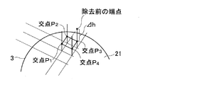
具体的に、除去量算出部305は、まず、砥石21の端面と工作物3の線分との交点を認識する。そして、図14に示すように、除去量算出部305は、1メッシュに4つの交点がある場合、その交点で形成される四角形□p1p2p3p4の面積(1メッシュの面積に相当)を算出する。ここで、交点が1メッシュに3つの場合、上記4つの場合と同様、四角形の面積が求められる。交点が1メッシュに2つの場合、1メッシュの面積の半分の値が算出される。交点が1メッシュに1つ以下の場合、計算を行わない。このように、除去量算出部105は、各メッシュで求めた面積を積算する。そして、その積算面積に、削られた高さΔh(すなわち、基準面z1から除去前の端点までの長さと、基準面z1から交点までの長さの差分)をかけられて除去量が算出される。なお、削られた高さを各メッシュの面積にかけて、後に体積を積算してもよい。式で表すと、除去量=Σ□p1p2p3p4×Δhとなる。
Specifically, the removal
図16を参照し演算をフローで説明すると、まず、砥石21が配置される(S901)。そして、Z軸方向から見た工作物3と砥石21との干渉をチェックする(S902)。そして、干渉がある場合(S903:Yes)、工作物3の線分長を端点が交点となるように変更する(S904)。干渉がない場合(S903:No)、線分長を変更せず、S905に進む。
The calculation will be described with reference to FIG. 16. First, the
そして、1ブロック動作(1指令値)が完了していれば(S905:Yes)、除去量が計算される(S906)。1ブロック動作が未完了であれば(S905:No)、除去量が計算されずS901に戻る。除去量が計算された後、次のブロックがあれば同様のステップを繰り返す。 If one block operation (one command value) is completed (S905: Yes), the removal amount is calculated (S906). If the one-block operation is not completed (S905: No), the removal amount is not calculated and the process returns to S901. After the removal amount is calculated, if there is a next block, the same steps are repeated.
工作物形状変更部306は、除去量算出部305で算出された除去量に基づいて、工作物形状記憶部301に記憶されている工作物3の端面形状を変更する。つまり、工作物形状記憶部301に記憶されている工作物3の端面形状を、除去後の形状に更新する。すなわち、工作物形状変更部306は、除去量算出部305で算出された除去量の部分が全て研削加工により削り取られたと仮定して、削り取られた後の工作物3の形状を更新している。
The workpiece
研削抵抗算出部307は、除去量算出部305で算出された除去量に基づいて、研削加工におけるZ軸方向の研削抵抗Fnを算出する。このZ軸方向の研削抵抗Fnの算出方法は、第一実施形態におけるX軸方向の研削抵抗Fnの算出方法と実質的に同様である。
The grinding
剛性記憶部308は、工作物剛性および砥石剛性を記憶している。工作物剛性は、研削盤2の主軸台23に支持された状態の工作物3に対して、Z軸方向の力を与えた場合における工作物3のZ軸方向の変位量に応じたものである。砥石剛性は、研削盤2の砥石台22に支持された状態の砥石21に対して、Z軸方向の力を与えた場合における砥石21のZ軸方向の変位量に応じたものである。
The
変位量算出部309は、Z軸方向の研削抵抗Fnに起因して砥石21と工作物3とがZ軸方向に相対変位する変位量Znを、剛性記憶部308に記憶された工作物剛性および砥石剛性に基づいて算出する。
The displacement
変位量補正部310は、算出された変位量Znに基づいて、Z軸離間距離算出部316におけるZ軸離間距離を補正する。この補正は、実質的に、第一実施形態におけるX軸離間距離の補正と同様である。
The displacement
砥石変形量算出部311は、Z軸方向の研削抵抗Fnに基づいて砥石21の変形量を算出し、砥石21の変形量に基づいて砥石形状記憶部302に記憶されている砥石21の端面形状を変更する。
The grindstone deformation
このように、びびりシミュレーション装置300によれば、工作物3の端面研削加工に対しても、より高精度にびびりシミュレーションを行うことができる。
As described above, according to the
<第四実施形態:端面研削加工>
第四実施形態のびびりシミュレーション装置400は、第三実施形態同様、工作物3の端面のびびり現象をシミュレーションする。ただし、第四実施形態においては、図17に示すように、砥石台22は、Z軸方向およびX軸方向に移動し(図17矢印参照)、工作物3の端面を研削加工する。図17は、第四実施形態における砥石21と工作物3とを示す模式平面図である。図17の工作物3は、例えばクランクシャフトである。
<Fourth embodiment: end face grinding>
The
びびりシミュレーション装置400について図18を参照して説明する。図18は、びびりシミュレーション装置400のブロック図である。ここで、第四実施形態のびびりシミュレーション装置400において、第一実施形態および第三実施形態のびびりシミュレーション装置100、300と同一構成については同一符号を付して説明を省略する。
The
図18に示すように、びびりシミュレーション装置400は、工作物形状記憶部301と、砥石形状記憶部302と、指令値記憶部103と、X軸離間距離算出部104と、Z軸相対位置算出部316と、除去量算出部405と、工作物形状変更部306と、研削抵抗算出部407と、剛性記憶部408と、変位量算出部409と、X軸変位量補正部410aと、Z軸変位量補正部410bと、砥石変形量算出部411と、びびり判定部112と、加工条件変更部113と、加工条件記憶部114と、剛性変更部115とを備えている。
As shown in FIG. 18, the
除去量算出部405は、工作物形状記憶部301に記憶された工作物3の端面形状、砥石形状記憶部302に記憶された砥石21の端面形状、X軸離間距離算出部104で算出されたX軸方向の離間距離、および、Z軸相対位置算出部316で算出されたZ軸方向の離間距離に基づいて、砥石21による工作物3の除去量を算出する。ここでの端面加工は、第三実施形態と異なり、砥石21をX軸方向に移動させると共に、砥石21をZ軸方向に移動させて行う。除去量の算出は、第三実施形態と同様にメッシュを用いて行う。
The removal
研削抵抗算出部407は、除去量算出部405で算出された除去量に基づいて、研削点における砥石移動方向(X軸方向およびZ軸方向)の研削抵抗Fnを算出する。さらに、研削抵抗算出部407は、研削抵抗Fnを、X軸方向の研削抵抗FWnxと、Z軸方向の研削抵抗FWnzとに分解する。研削抵抗Fnの算出方法は、第一実施形態におけるX軸方向の研削抵抗Fnの算出方法と実質的に同様である。
Based on the removal amount calculated by the removal
剛性記憶部408は、X軸方向およびZ軸方向のそれぞれに対して、工作物剛性および砥石剛性を記憶している。
The
変位量算出部409は、Z軸方向の研削抵抗FWnzに起因して砥石21と工作物3とがZ軸方向に相対変位する変位量Znzを、剛性記憶部408に記憶されたZ軸方向における工作物剛性および砥石剛性に基づいて算出する。さらに、変位量算出部409は、X軸方向の研削抵抗FWnxに起因して砥石21と工作物3とがX軸方向に相対変位する変位量Znxを、剛性記憶部408に記憶されたX軸方向における工作物剛性および砥石剛性に基づいて算出する。
The displacement
X軸変位量補正部410aは、算出された変位量Znxに基づいて、X軸離間距離算出部104におけるX軸離間距離を補正する。Z軸変位量補正部410bは、算出された変位量Znzに基づいて、Z軸相対位置算出部316におけるZ軸離間距離を補正する。これらの補正は、実質的に、第一実施形態におけるX軸離間距離の補正と同様である。
The X-axis displacement
砥石変形量算出部411は、研削抵抗FWnx、FWnzに基づいて砥石21の変形量を算出し、砥石21の変形量に基づいて砥石形状記憶部302に記憶されている砥石21の端面形状を変更する。
The grindstone deformation
このように、びびりシミュレーション装置400によれば、砥石21の移動方向がX軸方向およびZ軸方向である端面研削加工に対しても、より高精度にびびりシミュレーションを行うことができる。
Thus, according to
100、200、300、400:びびりシミュレーション装置、
2:研削盤、21:砥石、22:砥石台、23:主軸台、
3:工作物
100, 200, 300, 400: Chatter simulation device,
2: grinding machine, 21: grinding wheel, 22: grinding wheel head, 23: spindle head,
3: Workpiece
Claims (17)
前記工作物の形状を記憶する工作物形状記憶部と、
前記砥石の形状を記憶する砥石形状記憶部と、
前記研削加工における研削盤に対する指令値を記憶する指令値記憶部と、
前記指令値に基づいて、前記砥石が前記工作物に対して相対移動する方向である砥石移動方向における前記工作物と前記砥石との所定時間毎の相対位置を順に算出する相対位置算出部と、
前記相対位置が算出される毎に、前記工作物形状記憶部に記憶されている前記工作物の形状、前記砥石形状記憶部に記憶されている前記砥石の形状、および、前記相対位置に基づいて、前記砥石による前記工作物の除去量を算出する除去量算出部と、
前記除去量が算出される毎に、前記工作物形状記憶部に記憶されている前記工作物の形状を前記除去量に基づいて変更する工作物形状変更部と、
前記除去量が算出される毎に、前記研削加工における前記砥石移動方向の研削抵抗を前記除去量に基づいて算出する研削抵抗算出部と、
前記研削抵抗が算出される毎に、前記研削抵抗に起因して前記砥石と前記工作物とが前記砥石移動方向に相対変位する変位量を算出する変位量算出部と、
前記変位量が算出される毎に、前記相対位置算出部において次回算出される前記砥石移動方向の前記相対位置を前記変位量に基づいて補正する変位量補正部と、
前記工作物形状記憶部に記憶されている、前記工作物形状変更部により2回以上変更された前記工作物の形状に基づいて、びびりの有無を判定するびびり判定部と、
を備えることを特徴とするびびりシミュレーション装置。 A chatter simulation device that simulates a chatter phenomenon of the workpiece in a grinding process in which a grindstone to be rotated is brought into contact with a rotationally driven workpiece to grind the workpiece,
A workpiece shape storage unit for storing the shape of the workpiece;
A grinding wheel shape storage unit for storing the shape of the grinding wheel;
A command value storage unit for storing a command value for the grinding machine in the grinding process;
Based on the command value, a relative position calculation unit that sequentially calculates a relative position for each predetermined time between the workpiece and the grindstone in the grindstone moving direction in which the grindstone moves relative to the workpiece;
Each time the relative position is calculated, the shape of the workpiece shape storage unit stored in Tei Ru said workpiece, said grinding wheel shape storage unit stored in the shape of the grindstone Ru Tei, and, based on the relative position A removal amount calculation unit for calculating a removal amount of the workpiece by the grindstone;
Every time the removal amount is calculated, and the workpiece shape changing unit for changing the shape of the workpiece shape storage unit the workpiece stored in the basis of the removal amount,
Each time the removal amount is calculated, a grinding resistance calculation unit that calculates a grinding resistance in the grinding wheel moving direction in the grinding process based on the removal amount ;
A displacement amount calculating unit that calculates a displacement amount in which the grindstone and the workpiece are relatively displaced in the grindstone moving direction each time the grinding resistance is calculated ;
Each time the displacement amount is calculated, and the displacement amount correction unit that corrects, based the relative position of said grinding wheel movement direction calculated next time have contact with the relative position calculating unit on the displacement amount,
The workpiece shape storage unit is stored, based on the shape before Symbol workpieces that have changed more than once by the workpiece shape changing portion, and the chatter determination unit determines the presence or absence of chatter,
A chatter simulation apparatus comprising:
前記工作物形状記憶部は、前記工作物の周面形状を記憶し、
前記砥石形状記憶部は、前記砥石の周面形状を記憶し、
前記相対位置算出部は、前記工作物の軸心と前記砥石の軸心とのX軸方向の離間距離を算出し、
前記除去量算出部は、前記工作物形状記憶部に記憶されている前記工作物の周面形状、前記砥石形状記憶部に記憶されている前記砥石の周面形状、および、X軸方向の前記離間距離に基づいて、前記砥石による前記工作物の除去量を算出し、
前記工作物形状変更部は、前記工作物形状記憶部に記憶されている前記工作物の周面形状を前記除去量に基づいて変更する請求項1に記載のびびりシミュレーション装置。 The grindstone moving direction is the X-axis direction,
The workpiece shape storage unit stores a circumferential shape of the workpiece,
The grindstone shape storage unit stores a peripheral shape of the grindstone,
The relative position calculation unit calculates a separation distance in the X-axis direction between the axis of the workpiece and the axis of the grindstone,
The removal amount calculation unit, the peripheral surface shape of the workpiece is stored in the shape storage unit Tei Ru said workpiece, peripheral shape of the said grindstone Ru Tei stored in the grindstone shape storage unit, and the X-axis direction Based on the separation distance, calculate the removal amount of the workpiece by the grindstone,
The workpiece shape changing unit is chattering simulation apparatus according to the peripheral surface shape of the workpiece shape storage unit stored in Tei Ru said workpiece to claim 1 to change based on the removal amount.
前記工作物の軸直交方向断面が非真円形状である場合または前記工作物の軸心が前記工作物の回転中心から偏心した偏心形状である場合、
前記研削抵抗算出部は、前記除去量、前記指令値、前記工作物の周面形状、および、前記砥石の周面形状に基づいて、前記X軸方向および前記Y軸方向の研削抵抗を算出し、
前記変位量算出部は、さらに、前記Y軸方向の研削抵抗に基づいて前記Y軸方向の変位量を算出し、
前記びびりシミュレーション装置は、さらに、前記変位量が算出される毎に、前記Y軸方向の変位量に基づいて前記工作物の軸心と前記砥石の軸心とのY軸方向の離間距離を算出するY軸離間距離算出部を備え、
前記除去量算出部は、前記X軸方向および前記Y軸方向の離間距離に基づいて前記除去量を算出する請求項2に記載のびびりシミュレーション装置。 A direction perpendicular to the X-axis direction and perpendicular to the axis of the workpiece is defined as a Y-axis direction,
When the cross section in the direction perpendicular to the axis of the workpiece is a non-circular shape, or when the axis of the workpiece is an eccentric shape eccentric from the center of rotation of the workpiece,
The grinding resistance calculation unit calculates the grinding resistance in the X-axis direction and the Y-axis direction based on the removal amount, the command value, the peripheral surface shape of the workpiece, and the peripheral surface shape of the grindstone. ,
The displacement amount calculation unit further calculates a displacement amount in the Y-axis direction based on the grinding resistance in the Y-axis direction,
The chatter simulation apparatus further calculates a distance in the Y-axis direction between the axis of the workpiece and the axis of the grindstone based on the amount of displacement in the Y-axis direction each time the amount of displacement is calculated. A Y-axis separation distance calculation unit
The chatter simulation apparatus according to claim 2, wherein the removal amount calculation unit calculates the removal amount based on a separation distance in the X-axis direction and the Y-axis direction.
前記除去量算出部は、各前記線分と前記砥石の外縁線との交点に基づいて除去量を算出し、
前記工作物形状変更部は、前記交点を線分端点とし、前記工作物形状記憶部に記憶されている前記工作物の周面形状を変更する請求項2または3に記載のびびりシミュレーション装置。 The workpiece shape storage unit stores a plurality of line segments connecting a division point on a peripheral edge obtained by dividing the workpiece and the axis of the workpiece as a peripheral shape of the workpiece,
The removal amount calculation unit calculates a removal amount based on an intersection of each line segment and an outer edge line of the grindstone,
The workpiece shape changing unit, the intersection with a line segment end points, chatter simulation apparatus according to claim 2 or 3 changes the peripheral shape of the workpiece shape storage unit stored in Tei Ru said workpiece.
前記工作物形状記憶部は、前記工作物の端面形状を記憶し、
前記砥石形状記憶部は、前記砥石の端面形状を記憶し、
前記相対位置算出部は、前記工作物と前記砥石の端面とのZ軸方向の相対位置を算出し、
前記除去量算出部は、前記工作物形状記憶部に記憶されている前記工作物の端面形状、前記砥石形状記憶部に記憶されている前記砥石の端面形状、前記指令値に基づく前記砥石のX軸方向の位置、および、Z軸方向の前記相対位置に基づいて、前記砥石による前記工作物の除去量を算出し、
前記工作物形状変更部は、前記工作物形状記憶部に記憶されている前記工作物の端面形状を前記除去量に基づいて変更する請求項1に記載のびびりシミュレーション装置。 The grinding wheel moving direction is the Z-axis direction,
The workpiece shape storage unit stores an end face shape of the workpiece,
The grindstone shape storage unit stores the end face shape of the grindstone,
The relative position calculation unit calculates a relative position in the Z-axis direction between the workpiece and the end face of the grindstone,
The removal amount calculation unit, the end surface shape of the workpiece is stored in the shape storage unit Tei Ru said workpiece, the end face shape of said grinding wheel Ru Tei stored in the grindstone shape storage unit, X of the grinding wheel based on the command value Based on the position in the axial direction and the relative position in the Z-axis direction, the removal amount of the workpiece by the grindstone is calculated,
The workpiece shape changing unit is chattering simulation apparatus according to the end surface shape of the workpiece shape storage unit stored in Tei Ru said workpiece to claim 1 to change based on the removal amount.
前記工作物形状記憶部は、前記工作物の端面形状を記憶し、
前記砥石形状記憶部は、前記砥石の端面形状を記憶し、
前記相対位置算出部は、前記工作物の軸心と前記砥石の軸心とのX軸方向の離間距離、および、前記工作物と前記砥石の端面とのZ軸方向の相対位置を算出し、
前記除去量算出部は、前記工作物形状記憶部に記憶されている前記工作物の端面形状、前記砥石形状記憶部に記憶されている前記砥石の端面形状、X軸方向の前記離間距離、および、Z軸方向の前記相対位置に基づいて、前記砥石による前記工作物の除去量を算出し、
前記工作物形状変更部は、前記工作物形状記憶部に記憶されている前記工作物の端面形状を前記除去量に基づいて変更し、
前記研削抵抗算出部は、X軸方向の研削抵抗およびZ軸方向の研削抵抗を前記除去量に基づいて算出し、
前記変位量算出部は、前記X軸方向の研削抵抗に起因して前記砥石と前記工作物とがX軸方向に相対変位する変位量を算出し、前記Z軸方向の研削抵抗に起因して前記砥石と前記工作物とがZ軸方向に相対変位する変位量を算出し、
前記変位量補正部は、前記相対位置算出部において次回算出されるX軸方向の前記離間距離を前記X軸方向の変位量に基づいて補正し、前記相対位置算出部において次回算出されるZ軸方向の前記相対位置を前記Z軸方向の変位量に基づいて補正する請求項1に記載のびびりシミュレーション装置。 The whetstone moving directions are the X-axis direction and the Z-axis direction,
The workpiece shape storage unit stores an end face shape of the workpiece,
The grindstone shape storage unit stores the end face shape of the grindstone,
The relative position calculation unit calculates a distance in the X-axis direction between the axis of the workpiece and the axis of the grindstone, and a relative position in the Z-axis direction between the workpiece and the end face of the grindstone,
The removal amount calculation unit, the edge shapes of the workpiece is stored in the shape storage unit Tei Ru said workpiece, the end face shape of said grinding wheel Ru Tei stored in the grindstone shape storage unit, the distance between the X-axis direction, and , Based on the relative position in the Z-axis direction, calculate the removal amount of the workpiece by the grindstone,
The workpiece shape changing portion, an end surface shape of the workpiece shape storage unit stored in Tei Ru said workpiece to change in accordance with the removal amount,
The grinding resistance calculation unit calculates a grinding resistance in the X-axis direction and a grinding resistance in the Z-axis direction based on the removal amount ,
The displacement amount calculation unit calculates a displacement amount in which the grindstone and the workpiece are relatively displaced in the X-axis direction due to the grinding resistance in the X-axis direction, and originates in the grinding resistance in the Z-axis direction. A displacement amount in which the grindstone and the workpiece are relatively displaced in the Z-axis direction;
The displacement amount correction section, the distance between the X-axis direction calculated next time have contact with the relative position calculating section is corrected based on the displacement amount of the X-axis direction, calculates the next time to have you on the relative position calculating unit chatter simulation apparatus according to claim 1, corrected based on the relative position of the Z-axis direction which is the displacement amount of the Z-axis direction.
前記除去量算出部は、前記線分と前記砥石の端面との交点に基づいて除去量を算出し、
前記工作物形状変更部は、前記交点を線分端点とし、前記工作物形状記憶部に記憶されている前記工作物の端面形状を変更する請求項6または7に記載のびびりシミュレーション装置。 The workpiece shape storage unit divides a reference plane in the Z-axis direction of the workpiece into a mesh shape, and stores a plurality of line segments extending in the Z-axis direction from the intersection of the mesh as an end surface shape of the workpiece. ,
The removal amount calculation unit calculates a removal amount based on an intersection of the line segment and the end face of the grindstone,
The workpiece shape changing unit, the intersection with a line segment end points, chatter simulation apparatus according to claim 6 or 7 to change the end surface shape of the workpiece shape storage unit stored in Tei Ru said workpiece.
前記変位量算出部は、前記工作物剛性に基づいて前記変位量を算出する請求項1に記載のびびりシミュレーション装置。 Further, a stiffness memory for storing a workpiece stiffness corresponding to a displacement amount of the workpiece in the grinding wheel movement direction when a force in the grinding wheel movement direction is applied to the workpiece supported by the grinding machine. Part
The chatter simulation apparatus according to claim 1, wherein the displacement amount calculation unit calculates the displacement amount based on the workpiece rigidity.
前記変位量算出部は、前記砥石剛性に基づいて前記変位量を算出する請求項9または10に記載のびびりシミュレーション装置。 The rigidity storage unit stores a grindstone rigidity according to a displacement amount of the grindstone in the grindstone moving direction when a force in the grindstone moving direction is applied to the grindstone in a state supported by the grinder.
The chatter simulation apparatus according to claim 9 or 10, wherein the displacement amount calculation unit calculates the displacement amount based on the grindstone rigidity.
前記加工条件変更部は、前記びびり量が閾値以上の場合に、前記研削加工条件を変更する請求項12に記載のびびりシミュレーション装置。 The chatter determination unit calculates a chatter amount when there is the chatter,
The chatter simulation apparatus according to claim 12, wherein the machining condition changing unit changes the grinding condition when the amount of chatter is equal to or greater than a threshold value.
前記研削加工における研削盤制御装置に対する指令値を入力する指令値入力工程と、
前記指令値に基づいて、前記砥石が前記工作物に対して相対移動する方向である砥石移動方向における前記工作物と前記砥石との所定時間毎の相対位置を順に算出する相対位置算出工程と、
前記相対位置が算出される毎に、工作物形状記憶部に記憶されている前記工作物の形状、砥石形状記憶部に記憶されている前記砥石の形状、および、前記砥石移動方向の前記相対位置に基づいて、前記砥石による前記工作物の除去量を算出する除去量算出工程と、
前記除去量が算出される毎に、前記工作物形状記憶部に記憶されている前記工作物の形状を前記除去量に基づいて変更する工作物形状変更工程と、
前記除去量が算出される毎に、前記研削加工における前記砥石移動方向の研削抵抗を前記除去量に基づいて算出する研削抵抗算出工程と、
前記研削抵抗が算出される毎に、前記研削抵抗に起因して前記砥石と前記工作物とが前記砥石移動方向に相対変位する変位量を算出する変位量算出工程と、
前記変位量が算出される毎に、前記相対位置算出工程において次回算出される前記砥石移動方向の前記相対位置を前記変位量に基づいて補正する変位量補正工程と、
前記工作物形状記憶部に記憶されている、前記工作物形状変更工程で2回以上変更された前記工作物の形状に基づいて、びびりの有無を判定するびびり判定工程と、
を備えることを特徴とするびびりシミュレーション方法。 A chatter simulation method for simulating the chatter phenomenon of the workpiece in a grinding process for grinding the workpiece by bringing a grindstone to be rotated into contact with the workpiece to be rotated,
A command value input step for inputting a command value for the grinding machine control device in the grinding process;
Based on the command value, a relative position calculating step for sequentially calculating a relative position for each predetermined time between the workpiece and the grindstone in a grindstone moving direction that is a direction in which the grindstone moves relative to the workpiece;
Each time the relative position is calculated, the shape of the workpiece Ru Tei stored in the workpiece shape storage unit, the shape of the grindstone Ru Tei stored in the grindstone shape storage unit, and the relative position of said grinding wheel movement direction Based on the removal amount calculation step of calculating the removal amount of the workpiece by the grindstone,
Every time the removal amount is calculated, and the workpiece shape changing step of changing on the basis of the shape of the workpiece shape storage unit the workpiece Ru stored Tei in the removal amount,
Each time the removal amount is calculated, a grinding resistance calculation step of calculating a grinding resistance in the grinding wheel moving direction in the grinding process based on the removal amount ;
A displacement amount calculating step for calculating a displacement amount in which the grindstone and the workpiece are relatively displaced in the grindstone moving direction each time the grinding resistance is calculated ;
Each time the displacement amount is calculated, and the displacement amount correction step of correcting the basis of the relative position of the next calculated Ru said grinding wheel movement direction in the relative position calculating step to the amount of displacement,
A chatter determination step for determining the presence or absence of chatter based on the shape of the workpiece that has been stored twice or more in the workpiece shape change step, stored in the workpiece shape storage unit,
A chatter simulation method comprising:
Priority Applications (1)
| Application Number | Priority Date | Filing Date | Title |
|---|---|---|---|
| JP2008205651A JP5272569B2 (en) | 2007-08-10 | 2008-08-08 | Chatter simulation apparatus and chatter simulation method |
Applications Claiming Priority (3)
| Application Number | Priority Date | Filing Date | Title |
|---|---|---|---|
| JP2007209923 | 2007-08-10 | ||
| JP2007209923 | 2007-08-10 | ||
| JP2008205651A JP5272569B2 (en) | 2007-08-10 | 2008-08-08 | Chatter simulation apparatus and chatter simulation method |
Publications (2)
| Publication Number | Publication Date |
|---|---|
| JP2009064426A JP2009064426A (en) | 2009-03-26 |
| JP5272569B2 true JP5272569B2 (en) | 2013-08-28 |
Family
ID=40558926
Family Applications (1)
| Application Number | Title | Priority Date | Filing Date |
|---|---|---|---|
| JP2008205651A Expired - Fee Related JP5272569B2 (en) | 2007-08-10 | 2008-08-08 | Chatter simulation apparatus and chatter simulation method |
Country Status (1)
| Country | Link |
|---|---|
| JP (1) | JP5272569B2 (en) |
Families Citing this family (7)
| Publication number | Priority date | Publication date | Assignee | Title |
|---|---|---|---|---|
| JP5239650B2 (en) * | 2008-09-02 | 2013-07-17 | 株式会社ジェイテクト | Wear amount simulation device for rotating tools |
| JP2014214420A (en) * | 2013-04-22 | 2014-11-17 | 清水建設株式会社 | Method for designing base isolation wall |
| JP2018112934A (en) * | 2017-01-12 | 2018-07-19 | トヨタ自動車株式会社 | Design support device for tooling and machining jig |
| JP7412695B2 (en) | 2019-10-03 | 2024-01-15 | 慶應義塾 | Machine tools, numerical control devices and vibration suppression methods |
| WO2023047437A1 (en) * | 2021-09-21 | 2023-03-30 | 株式会社ジェイテクト | Processing estimation device |
| WO2023058107A1 (en) * | 2021-10-05 | 2023-04-13 | 株式会社ジェイテクト | Machining device |
| CN116100318B (en) * | 2023-04-06 | 2023-07-28 | 四川省机械研究设计院(集团)有限公司 | Turning and milling compound machine tool processing method, device, equipment and storage medium |
Family Cites Families (3)
| Publication number | Priority date | Publication date | Assignee | Title |
|---|---|---|---|---|
| JP3440528B2 (en) * | 1994-02-02 | 2003-08-25 | トヨタ自動車株式会社 | 3D model creation method |
| JP4812224B2 (en) * | 2000-06-30 | 2011-11-09 | 株式会社森精機製作所 | Machining simulation apparatus and method in NC machining |
| JP4443823B2 (en) * | 2002-12-04 | 2010-03-31 | 住友重機械工業株式会社 | Grinding machine machining simulation system, grinding machine machining simulation method, and grinding machine machining simulation program |
-
2008
- 2008-08-08 JP JP2008205651A patent/JP5272569B2/en not_active Expired - Fee Related
Also Published As
| Publication number | Publication date |
|---|---|
| JP2009064426A (en) | 2009-03-26 |
Similar Documents
| Publication | Publication Date | Title |
|---|---|---|
| JP5272569B2 (en) | Chatter simulation apparatus and chatter simulation method | |
| JP5213442B2 (en) | Raster cutting technology for ophthalmic lenses | |
| JP5962242B2 (en) | Grinding equipment | |
| CN106378668B (en) | A kind of control method of five axis double-ended grinding machine | |
| JP2020015129A (en) | Grinding wheel surface state estimation model creation device, grinding wheel surface state estimation device, operation command data adjustment model creation device for grinder and operation command data updating device for grinder | |
| JP2020069600A (en) | Machine tool | |
| JP6302794B2 (en) | Rotation speed display method | |
| JP6911426B2 (en) | Grinding simulation equipment and method | |
| JP2020044620A (en) | Generation device for learning model relating to grinding, estimation device and operation command data renewal device | |
| JP2013071187A (en) | Tool path-calculating device, tool path-calculating method, and processing device | |
| WO2018011990A1 (en) | Machining program generation device and machining method | |
| JP4940904B2 (en) | Bulk quantity measuring device | |
| JP7172636B2 (en) | Machine tool maintenance support device and machine tool system | |
| JP4261493B2 (en) | Dressing device, grinding device, dressing method, and numerical control program | |
| CN111716251B (en) | Method for optimizing finishing process of precision bearing grinding diamond roller | |
| JP7451949B2 (en) | Machining quality prediction system | |
| JP2015147272A (en) | Simulation device of coreless shoe grinding and simulation method of coreless shoe grinding | |
| JP2012168742A (en) | Machining center provided with grindstone wear correction function | |
| JP2021171833A (en) | Surface roughness estimation system | |
| WO2023047437A1 (en) | Processing estimation device | |
| JP2017177262A (en) | Shaving cutter grinder | |
| JP7451948B2 (en) | Machining quality prediction system | |
| WO2024075284A1 (en) | Contact dynamic stiffness calculation system, machining estimation device, and proccessing system | |
| WO2024075303A1 (en) | Workpiece mass determination device, machining estimation device, and machining system | |
| JP2002160103A (en) | Curved surface machine method and its device |
Legal Events
| Date | Code | Title | Description |
|---|---|---|---|
| A621 | Written request for application examination |
Free format text: JAPANESE INTERMEDIATE CODE: A621 Effective date: 20110801 |
|
| A521 | Request for written amendment filed |
Free format text: JAPANESE INTERMEDIATE CODE: A523 Effective date: 20120720 |
|
| A977 | Report on retrieval |
Free format text: JAPANESE INTERMEDIATE CODE: A971007 Effective date: 20121205 |
|
| A131 | Notification of reasons for refusal |
Free format text: JAPANESE INTERMEDIATE CODE: A131 Effective date: 20121218 |
|
| A521 | Request for written amendment filed |
Free format text: JAPANESE INTERMEDIATE CODE: A523 Effective date: 20130218 |
|
| TRDD | Decision of grant or rejection written | ||
| A01 | Written decision to grant a patent or to grant a registration (utility model) |
Free format text: JAPANESE INTERMEDIATE CODE: A01 Effective date: 20130416 |
|
| A61 | First payment of annual fees (during grant procedure) |
Free format text: JAPANESE INTERMEDIATE CODE: A61 Effective date: 20130429 |
|
| R150 | Certificate of patent or registration of utility model |
Ref document number: 5272569 Country of ref document: JP Free format text: JAPANESE INTERMEDIATE CODE: R150 |
|
| LAPS | Cancellation because of no payment of annual fees |