JP5266501B2 - Oil / water separation device and oil / water separation system - Google Patents

Oil / water separation device and oil / water separation system Download PDF

Info

Publication number
JP5266501B2
JP5266501B2 JP2008307260A JP2008307260A JP5266501B2 JP 5266501 B2 JP5266501 B2 JP 5266501B2 JP 2008307260 A JP2008307260 A JP 2008307260A JP 2008307260 A JP2008307260 A JP 2008307260A JP 5266501 B2 JP5266501 B2 JP 5266501B2
Authority
JP
Japan
Prior art keywords
oil
filter element
water
adsorbent
housing
Prior art date
Legal status (The legal status is an assumption and is not a legal conclusion. Google has not performed a legal analysis and makes no representation as to the accuracy of the status listed.)
Active
Application number
JP2008307260A
Other languages
Japanese (ja)
Other versions
JP2009269017A (en
Inventor
昭宏 竹前
竜 松橋
Current Assignee (The listed assignees may be inaccurate. Google has not performed a legal analysis and makes no representation or warranty as to the accuracy of the list.)
Orion Machinery Co Ltd
Original Assignee
Orion Machinery Co Ltd
Priority date (The priority date is an assumption and is not a legal conclusion. Google has not performed a legal analysis and makes no representation as to the accuracy of the date listed.)
Filing date
Publication date
Application filed by Orion Machinery Co Ltd filed Critical Orion Machinery Co Ltd
Priority to JP2008307260A priority Critical patent/JP5266501B2/en
Publication of JP2009269017A publication Critical patent/JP2009269017A/en
Application granted granted Critical
Publication of JP5266501B2 publication Critical patent/JP5266501B2/en
Active legal-status Critical Current
Anticipated expiration legal-status Critical

Links

Images

Abstract

<P>PROBLEM TO BE SOLVED: To increase effective filling capacity of an oil adsorption material while keeping a foreign matter collection function. <P>SOLUTION: The filter element 2a includes: a filter element vessel 11 for oil/water separator 1a, formed into a hollow columnar body with a bottom wall 21a formed at one end of a peripheral wall 21c of a vessel body 21 and a lid 22 mounted on the other end to contain the oil adsorption materials 12a, 12b and nonwoven fabric 13, formed with an inflow port 21b at the bottom wall 21a and an outflow port 22a at the lid 22, and mounted in a second housing 32 with a circumferential part A of the bottom wall 21a abutting on the inner face of a bottom wall 32a; and the oil adsorption materials 12a, 12b filled in the vessel 11. A slit part 21d from the surface of the bottom wall 21a to the surface of the peripheral wall 21c is formed on the circumferential part A to compose the vessel 11, and the nonwoven fabric 13 (emulsion breaking material) is disposed to block the inflow port 21b. <P>COPYRIGHT: (C)2010,JPO&amp;INPIT

Description

本発明は、フィルタエレメント用容器に油吸着材が収容されたフィルタエレメントを備えて圧縮空気除湿装置のドレン水のように油分が混入した排水から油分を除去する油水分離装置および油水分離システムに関するものである。 The present invention relates to oil-water separator and oil-water separation system for removing oil from the wastewater oil is mixed as drain water of the compressed air dehumidifier comprises a filter elementary bets oil sorbent is contained in a container for the filter element Is.

この種の油水分離装置の一般的な構造は、本願出願人による下記の特許文献1にも記載されているように、ハウジングと、このハウジング内に収容されるフィルタとを備えた構造となっている。この場合、ハウジングは、配管(ドレン水の供給用配管およびドレン水の排出用配管)に接続された第1のハウジングと、フィルタ(フィルタエレメント)を収容する第2のハウジングとで構成されている。フィルタエレメントは、中筒と、この中筒内に充填された油吸着材とで構成されている。また、フィルタエレメントは、一端側がドレン水の供給用配管と連結された状態でハウジング内に配置されている。この油水分離装置では、供給用配管から流入したドレン水は、一端側からフィルタエレメント内に入り、油分が油吸着材で吸着され、フィルタエレメントの他端側からハウジング内に流出する。さらに、ドレン水は、ハウジングの内周面とフィルタエレメントの外周面との間の隙間を経由して排出用配管から排出される。   The general structure of this type of oil-water separator is a structure including a housing and a filter accommodated in the housing, as described in the following Patent Document 1 by the applicant of the present application. Yes. In this case, the housing is composed of a first housing connected to pipes (drain water supply pipe and drain water discharge pipe) and a second housing that houses a filter (filter element). . The filter element is composed of a middle cylinder and an oil adsorbent filled in the middle cylinder. Moreover, the filter element is arrange | positioned in the housing in the state in which the one end side was connected with the piping for drain water supply. In this oil / water separator, the drain water flowing in from the supply pipe enters the filter element from one end side, the oil is adsorbed by the oil adsorbing material, and flows out into the housing from the other end side of the filter element. Further, the drain water is discharged from the discharge pipe via a gap between the inner peripheral surface of the housing and the outer peripheral surface of the filter element.

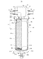
ところで、ドレン水には、油分だけでなく異物が混入する場合もあり、この異物を油水分離装置にて捕集したいという要請がある。そこで、出願人は、図7に示すような油水分離装置51を既に開発している。この油水分離装置51は、異物捕集手段57を備えたフィルタエレメント52を備えている。このフィルタエレメント52は、円筒状の本体53と、中央にドレン出口54aを有して本体53の上部側を仕切る円形の上部仕切板54と、中央にドレン入口55aを有すると共に周辺部に下側へ延出する脚部55bを有して本体53の下部を仕切る下部仕切板55とを有し、本体53内における上部仕切板54と下部仕切板55との間に吸着材56が充填される共に、脚部55bに異物捕集手段(小孔)57が配設されている。この油水分離装置51では、フィルタエレメント52に異物捕集手段57が配設されているため、ドレン水に含まれる異物58をフィルタエレメント52で捕集して除去することが可能となっている。また、フィルタエレメント52単位で交換可能となるため、吸着材56の交換が容易になっている。
特開2001−113269号公報(第2−3頁、第1図)
By the way, not only oil but also foreign matters may be mixed in the drain water, and there is a demand for collecting these foreign matters with an oil-water separator. Therefore, the applicant has already developed an oil / water separator 51 as shown in FIG. The oil / water separator 51 includes a filter element 52 including a foreign matter collecting means 57. The filter element 52 has a cylindrical main body 53, a circular upper partition plate 54 having a drain outlet 54a in the center and partitioning the upper side of the main body 53, a drain inlet 55a in the center, and a lower side at the periphery. And a lower partition plate 55 that divides the lower portion of the main body 53, and the adsorbent 56 is filled between the upper partition plate 54 and the lower partition plate 55 in the main body 53. In both cases, a foreign matter collecting means (small hole) 57 is disposed on the leg portion 55b. In the oil / water separator 51, since the foreign matter collecting means 57 is disposed in the filter element 52, the foreign matter 58 contained in the drain water can be collected and removed by the filter element 52. Further, since the filter element 52 can be replaced in units, the replacement of the adsorbent 56 is facilitated.
Japanese Patent Laid-Open No. 2001-113269 (page 2-3, FIG. 1)

ところが、本願発明者が、出願人の開発した上記の油水分離装置についてさらに検討を加えた結果、異物捕集手段57を配設した脚部55bの存在により、フィルタエレメント52における吸着材56の充填有効容積が減少していることを見出した。   However, as a result of further examination of the above oil / water separator developed by the applicant, the inventor of the present application has filled the adsorbent 56 in the filter element 52 due to the presence of the leg 55b provided with the foreign matter collecting means 57. It was found that the effective volume was decreasing.

本発明は、かかる課題を解決すべくなされたものであり、異物捕集機能を有しつつ、油吸着材の充填有効容積を増大させ得るフィルタエレメント用容器を有するフィルタエレメントを備えた油水分離装置および油水分離システムを提供することを主目的とする。 The present invention has been made in order to solve such problems, and has an oil / water separation device including a filter element having a container for a filter element capable of increasing the effective filling volume of an oil adsorbent while having a foreign matter collecting function. The main objective is to provide an oil-water separation system.

上記目的を達成すべく請求項1記載の油水分離装置は、フィルタエレメント用容器、および当該フィルタエレメント用容器内に充填された油吸着材を有するフィルタエレメントと、処理対象のドレン水を供給する供給側配管を接続可能な第1接続口、および処理を完了したドレン水を排出する排出側配管を接続可能な第2接続口がそれぞれ設けられると共に前記フィルタエレメントが取り外し可能に装着される第1のハウジング、並びに当該第1のハウジングに装着された前記フィルタエレメントを覆うようにして当該第1のハウジングに対して取り外し可能に装着される有底筒状の第2のハウジングを有するフィルタハウジングとを備えて構成された油水分離装置であって、前記フィルタエレメント用容器が、筒状の周壁および当該周壁の両端部に配設された一対の側壁で中空柱体に形成されて内部に前記油吸着材を収容可能に構成され、かつ前記第1接続口から前記第2のハウジングの内周面と前記周壁の外周面との間の隙間を通過して当該第2のハウジングの底壁と前記一対の側壁のうちの一方の側壁との間の隙間に流入した前記処理対象のドレン水を当該フィルタエレメント用容器内に流入させる流入口が当該一方の側壁に形成されると共に前記第2接続口に連通する流出口が他方の側壁に形成されて、前記第2のハウジングにおける前記底壁の内面に当該一方の側壁の周縁部が当接した状態で前記フィルタハウジング内に装着可能に構成され、かつ、前記一方の側壁の表面から前記周壁の表面に至るスリット部が前記周縁部に形成され、前記フィルタエレメントには、前記フィルタエレメント用容器における前記流入口を閉塞するようにしてシート状のエマルジョン破壊材が配設されている。 In order to achieve the above object, the oil / water separator according to claim 1 is a filter element container, a filter element having an oil adsorbent filled in the filter element container, and a supply for supplying drain water to be treated. A first connection port to which a side pipe can be connected and a second connection port to which a discharge side pipe for discharging drain water that has been processed is connected, and the filter element is detachably mounted. And a filter housing having a bottomed cylindrical second housing that is detachably attached to the first housing so as to cover the filter element attached to the first housing. an oil-water separation device configured Te in the container filter element, the cylindrical wall and the peripheral wall Wherein a pair of side walls disposed at an end portion formed in a hollow pillar body configured to accommodate the oil adsorbent therein, and the inner peripheral surface of the second housing from the first connection port and the peripheral wall The drain water to be treated passes through the gap between the outer peripheral surface of the second housing and flows into the gap between the bottom wall of the second housing and one of the pair of side walls . An inflow port for flowing into the container is formed on the one side wall, and an outflow port communicating with the second connection port is formed on the other side wall, and the one on the inner surface of the bottom wall in the second housing. wherein is configured to be mounted in the filter housing, and a slit portion extending to the surface of the peripheral wall from a surface of said one side wall is formed in the peripheral portion, the filter element in a state where the peripheral edge portion of the side wall of abuts Before The inlet in the container for the filter element so as to close the sheet-like emulsion breaking material is disposed.

請求項記載の油水分離装置は、請求項1記載の油水分離装置において、前記フィルタエレメントが、前記油吸着材としてのシート状吸着材および当該油吸着材としての短冊状吸着材の少なくとも一方が充填された第1の油吸着層と、前記油吸着材としての細紐状吸着材および当該油吸着材としての綿状吸着材の少なくとも一方が充填された第2の油吸着層とが前記エマルジョン破壊材の上にこの順で設けられて構成されている。 Oil-water separation apparatus of claim 2, in oil-water separation apparatus of claim 1 Symbol mounting, the filter element, at least one strip-shaped adsorbent as a sheet-like adsorbent and the oil adsorbent as the oil adsorbent And a second oil adsorption layer filled with at least one of a fine string adsorbent as the oil adsorbent and a cotton adsorbent as the oil adsorbent. It is provided in this order on the emulsion breaking material.

請求項記載の油水分離装置は、請求項1記載の油水分離装置において、前記フィルタエレメントが、前記油吸着材としての細紐状吸着材および当該油吸着材としての綿状吸着材の少なくとも一方が充填された油吸着層が前記エマルジョン破壊材の上に設けられて構成されている。 The claim 3 oil-water separation apparatus, wherein in the oil-water separation apparatus of claim 1 Symbol mounting, the filter element, flocculent adsorbent as fine string-like adsorbent and the oil adsorbent as the oil adsorbent least An oil adsorbing layer filled with one is provided on the emulsion breaking material.

請求項記載の油水分離装置は、請求項1からのいずれかに記載の油水分離装置において、前記フィルタエレメント用容器が、筒状の容器本体および当該容器本体に装着される蓋体とを備え、当該蓋体が前記一方の側壁または前記他方の側壁として構成されている。 4. Oil-water separation apparatus described, in the oil-water separation apparatus according to any one of claims 1 to 3, container the filter element, and a lid which is mounted in a cylindrical container body and the container body And the lid is configured as the one side wall or the other side wall.

請求項記載の油水分離装置は、請求項1からのいずれかに記載の油水分離装置において、前記フィルタエレメントにおいて、前記エマルジョン破壊材前記流入口からドーム状に突出している。 Oil-water separation apparatus of claim 5, wherein, in the oil-water separator according to any one of claims 1 to 4, in the filter element, wherein the emulsion breaking member protrudes from said inlet in a dome shape.

請求項記載の油水分離システムは、粗処理用フィルタエレメントとしてのフィルタエレメントが装着された請求項2記載の油水分離装置で構成された第1の油水分離装置と、本処理用フィルタエレメントとしてのフィルタエレメントが装着された請求項3記載の油水分離装置で構成された第2の油水分離装置とを備え、処理対象のドレン水が前記第1の油水分離装置および前記第2の油水分離装置をこの順で通過するように当該両油水分離装置が連結されている。 Oil-water separation system of claim 6 wherein the first and oil-water separating apparatus off I filter element as the filter element for coarse process is constituted by oil-water separation apparatus of the attached claim 2, as a filter element for the present process the full I filter element and a second oil-water separation apparatus which is constituted by oil-water separation apparatus of claim 3 which is mounted, wherein the drain water to be processed first oil-water separator and the second oil-water separation The oil-water separators are connected so as to pass through the device in this order.

請求項1記載の油水分離装置では、フィルタエレメント用容器の一方の側壁の周縁部が第2のハウジングにおける底壁の内面に当接した状態でフィルタハウジング内に装着され、一方の側壁の表面から周壁の表面に至るスリット部がこのフィルタエレメント用容器の周縁部に形成されたフィルタエレメント用容器と、フィルタエレメント用容器内に充填された油吸着材とを備えると共に、フィルタエレメント用容器におけるドレン水の流入口を閉塞するようにしてシート状のエマルジョン破壊材が配設されてフィルタエレメントが構成されている。したがって、この油水分離装置によれば、フィルタエレメント用容器の一方の側壁をフィルタハウジング(第2のハウジング)の底壁と直接当接させることで油吸着材の充填有効容積を増大させつつ、スリット部を異物捕集部として機能させてドレン水に含まれている異物を捕集することができるだけでなく、油吸着材に付着し難い(油吸着材によって除去し難い)エマルジョンが含まれている処理対象のドレン水がシート状のエマルジョン破壊材を通過する際にエマルジョン破壊(油分および水分の分離)されるため、処理対象のドレン水からエマルジョン化した油分を確実に取り除くことができる。また、フィルタエレメント用容器に対するスリット部の形成によって異物の捕集機能を確保しつつ、フィルタエレメント用容器での油吸着材の充填有効容積の増大によって油水分離機能を長期間に亘って発揮させることができる。したがって、この油水分離装置によれば、フィルタエレメントの長寿命化、言い換えれば、交換回数を低減することができる。 In the oil-water separator according to claim 1, the peripheral portion of one side wall of the filter element container is mounted in the filter housing in a state of being in contact with the inner surface of the bottom wall of the second housing, and from the surface of the one side wall. The filter element container having a slit portion reaching the surface of the peripheral wall formed in the peripheral edge of the filter element container, and an oil adsorbent filled in the filter element container, and drain water in the filter element container A filter element is configured by disposing a sheet-like emulsion breaking material so as to close the inflow port. Therefore, according to the oil / water separator, the one side wall of the filter element container is brought into direct contact with the bottom wall of the filter housing (second housing) , thereby increasing the effective volume for filling the oil adsorbing material and the slit. Not only can collect the foreign matter contained in the drain water by making the part function as a foreign matter collecting part, but also contains an emulsion that is difficult to adhere to the oil adsorbent (it is difficult to remove by the oil adsorbent) Since the drain water to be treated passes through the sheet-like emulsion breaking material, the emulsion is broken (separation of oil and moisture), so that the emulsified oil can be reliably removed from the drain water to be treated. In addition, the oil / water separation function can be demonstrated over a long period of time by increasing the effective filling capacity of the oil adsorbent in the filter element container while securing the foreign substance collecting function by forming a slit portion for the filter element container. Can do. Therefore, according to this oil-water separator, the life of the filter element can be extended, in other words, the number of replacements can be reduced.

さらに、請求項記載の油水分離装置によれば、シート状吸着材および短冊状吸着材の少なくとも一方を充填した第1の油吸着層と、細紐状吸着材および綿状吸着材の少なくとも一方を充填した第2の油吸着層とをエマルジョン破壊材の上にこの順で設けてフィルタエレメントを構成したことにより、エマルジョン破壊材によってエマルジョン破壊された直後に、第1の油吸着層において油吸着材によって油分が吸着されるため、エマルジョン破壊した油分および水分が再びエマルジョン化する事態を回避して油分を確実に取り除くことができる。また、このフィルタエレメントを備えた油水分離装置によれば、第1の油吸着層において比較的大きな油分の塊だけが除去されるため、例えばシート状のエマルジョン破壊材の直ぐ後ろに第2の油吸着層を設ける構成と比較して、第1の油吸着層を構成する油吸着材が短期間で目詰まりする事態を回避して十分に長い期間に亘って粗処理用フィルタエレメントの浄化能力を維持することができ、しかも、第1の油吸着層において取り除くことができなかった油分を第2の油吸着層において十分に取り除くことができる。 Furthermore, according to the oil-water separator according to claim 2 , at least one of the first oil adsorption layer filled with at least one of the sheet-like adsorbent and the strip-like adsorbent, and the fine string adsorbent and the cotton-like adsorbent. The filter element is formed by providing the second oil adsorbing layer filled with the oil on the emulsion breaking material in this order, so that the oil adsorbing in the first oil adsorbing layer immediately after the emulsion breaking by the emulsion breaking material. Since the oil is adsorbed by the material, it is possible to reliably remove the oil by avoiding the situation where the oil and water whose emulsion has been broken are re-emulsified. Further, according to the oil / water separator provided with this filter element , only a relatively large lump of oil is removed in the first oil adsorbing layer. For example, the second oil is immediately behind the sheet-like emulsion breaking material. Compared with the configuration in which the adsorption layer is provided, the purification capability of the rough processing filter element can be improved over a sufficiently long period by avoiding a situation where the oil adsorbent constituting the first oil adsorption layer is clogged in a short period of time. In addition, the oil that could not be removed in the first oil adsorption layer can be sufficiently removed in the second oil adsorption layer.

また、請求項記載の油水分離装置によれば、細紐状吸着材および綿状吸着材の少なくとも一方を充填した油吸着層をエマルジョン破壊材の上に設けてフィルタエレメントを構成したことにより、エマルジョン破壊材によってエマルジョン破壊された直後に、油吸着層を構成する油吸着材によって油分が吸着されるため、エマルジョン破壊した油分および水分が再びエマルジョン化する事態を回避して油分を確実に取り除くことができる。 Moreover, according to the oil-water separator according to claim 3 , by providing the oil adsorbing layer filled with at least one of the fine string adsorbent and the cotton adsorbent on the emulsion breaking material, the filter element is configured. Immediately after the emulsion breakage by the emulsion breaker, the oil is adsorbed by the oil adsorbent constituting the oil adsorbing layer, so that the oil and moisture that breaks the emulsion are prevented from re-emulsifying and the oil is reliably removed. Can do.

さらに、請求項記載の油水分離装置によれば、筒状の容器本体と蓋体とでフィルタエレメント用容器を構成したことにより、蓋体を外すことによって油吸着材を容易に交換することができるため、フィルタエレメント用容器を使い捨てることなく、再利用することができる。 Furthermore, according to the oil-water separator according to claim 4 , since the filter element container is constituted by the cylindrical container body and the lid, the oil adsorbent can be easily replaced by removing the lid. Therefore, the filter element container can be reused without being disposable.

また、請求項記載の油水分離装置によれば、フィルタエレメント用容器の一方の側壁に形成された流入口からエマルジョン破壊材がドーム状に突出しているため、流入口から露出するエマルジョン破壊材の表面積(捕集面積)が、流入口においてエマルジョン破壊材が平面状態となるときと比較して増加している。したがって、このフィルタエレメントを備えた油水分離装置によれば、油分や異物の付着によるエマルジョン破壊材の目詰まりを低減することができる結果、フィルタエレメント全体および油水分離装置としての目詰まりを低減することができる。 Further, according to the oil-water separator according to claim 5, since the emulsion breaking material protrudes in a dome shape from the inflow port formed on one side wall of the filter element container, the emulsion breaking material exposed from the inflow port The surface area (collection area) is increased compared to when the emulsion breaking material is in a flat state at the inlet. Therefore, according to the oil / water separator provided with this filter element , it is possible to reduce clogging of the emulsion breaking material due to adhesion of oil and foreign matter, and as a result, the filter element as a whole and the clogging as the oil / water separator can be reduced. Can do.

また、請求項記載の油水分離システムによれば、粗処理用フィルタエレメントが装着された第1の油水分離装置と、本処理用フィルタエレメントが装着された第2の油水分離装置とを備え、処理対象のドレン水が第1の油水分離装置および第2の油水分離装置をこの順で通過するように両油水分離装置を連結したことにより、第1の油水分離装置における粗処理用フィルタエレメントで除去し切れなかった油分や異物を第2の油水分離装置における本処理用フィルタエレメントによって確実に除去することができる。 Further, according to the oil-water separation system of claim 6, the oil-water separation system includes the first oil-water separation device to which the rough processing filter element is attached, and the second oil-water separation device to which the treatment filter element is attached. By connecting the two oil-water separators so that the drain water to be treated passes through the first oil-water separator and the second oil-water separator in this order, the rough processing filter element in the first oil-water separator Oil and foreign matters that could not be removed can be reliably removed by the main filter element in the second oil / water separator.

以下、添付図面を参照して、本発明に係る油水分離装置および油水分離システムの最良の形態について説明する。 Hereinafter, with reference to the accompanying drawings, illustrating the best mode of engagement Ru oil-water separator and oil-water separation system of the present invention.

最初に、油水分離システムS1(油水分離装置1a,1b)の構成について、図面を参照して説明する。   Initially, the structure of oil-water separation system S1 (oil-water separation apparatus 1a, 1b) is demonstrated with reference to drawings.

図1に示す油水分離システムS1は、本発明に係る油水分離システムの一例であって、本発明における油水分離装置の一例である油水分離装置1a,1bを備えて構成されている。油水分離装置1aは、本発明における第1の油水分離装置の一例であって、図5に示すように、フィルタエレメント2a(本発明におけるフィルタエレメントの一例)および本体(本発明におけるフィルタハウジング)3を備えている。また、油水分離装置1bは、本発明における第2の油水分離装置の一例であって、図6に示すように、フィルタエレメント2b(本発明におけるフィルタエレメントの他の一例)および本体(本発明におけるフィルタハウジング)3を備えている。この場合、図1に示すように、この油水分離システムS1では、上流側に配置された油水分離装置1aにドレン配管における供給側配管4が接続されると共に、下流側に配置された油水分離装置1bにドレン配管における排出側配管5が連結され、かつ、油水分離装置1a,1bが連結用配管6を介して連結されて、供給側配管4から流入するドレン水に含まれている油分および異物を分離して排出側配管5に排出する機能を備えている。 The oil / water separation system S1 shown in FIG. 1 is an example of the oil / water separation system according to the present invention, and includes oil / water separators 1a and 1b which are examples of the oil / water separator in the present invention. Oil-water separator 1a is an example of a first oil-water separation apparatus of the present invention, as shown in FIG. 5, the filter element 2a (an example of a filter element definitive the present invention) and the body (filter housing in the present invention) 3 is provided. Also, oil-water separation apparatus 1b is an example of a second oil-water separation apparatus of the present invention, as shown in FIG. 6, (another example of a filter element definitive the present invention) a filter element 2b and the body (the present invention The filter housing 3 in FIG. In this case, as shown in FIG. 1, in this oil-water separation system S1, the supply-side piping 4 in the drain pipe is connected to the oil-water separation device 1a arranged on the upstream side, and the oil-water separation device arranged on the downstream side The drain side pipe 5 in the drain pipe is connected to 1b, and the oil / water separators 1a and 1b are connected via the connecting pipe 6, so that the oil and foreign matter contained in the drain water flowing from the supply side pipe 4 Is separated and discharged to the discharge side pipe 5.

フィルタエレメント2aは、本発明における粗処理用フィルタエレメントの一例であって、図5に示すように、フィルタエレメント用容器11と、フィルタエレメント用容器11内に収容された油吸着材12a,12bおよび不織布13とを備えている。本例では、フィルタエレメント用容器11は、一端側(図5中の下端側)が底壁(本発明における周壁の両端部に配設された一対の側壁のうちの一方の側壁)21aによって閉塞されると共に他端側(図5中の上端側)が開放された筒状(一例として円筒状)の容器本体21と、容器本体21の他端側に装着(一例として螺合によって装着)された蓋体(本発明における一対の側壁のうちの他方の側壁)22とを備えている。また、容器本体21の底壁21aには、図3,5に示すように、その中央部位に流入口21b(一例として円形の1つの開口部)が形成されている。   The filter element 2a is an example of a rough processing filter element according to the present invention. As shown in FIG. 5, the filter element container 11 and oil adsorbents 12a, 12b accommodated in the filter element container 11 and A nonwoven fabric 13 is provided. In this example, the filter element container 11 has one end side (the lower end side in FIG. 5) closed by a bottom wall (one side wall of a pair of side walls disposed at both ends of the peripheral wall in the present invention) 21a. At the same time, the other end side (the upper end side in FIG. 5) is opened (mounted as an example) by a cylindrical (mainly cylindrical) container body 21 and the other end side of the container body 21 (attached by screwing as an example). And a lid (the other side wall of the pair of side walls in the present invention) 22. Further, as shown in FIGS. 3 and 5, the bottom wall 21 a of the container body 21 is formed with an inflow port 21 b (for example, one circular opening) at the center portion thereof.

また、容器本体21は、フィルタエレメント2aとして構成された状態で後述するように本体3内に装着された際には、図5に示すように、底壁21aの周縁部A(リブ状に突出した部位)が本体3の底面(後述するドレン口の形成面)と当接するが、この底壁21aの周縁部Aの表面には、図2〜5に示すように、底壁21aの表面(外面)から周壁21c(底壁21aを除く筒状の部位)の表面(外面)に至るスリット部21dが1または2以上(本例では複数(一例として4つ))形成されている。このスリット部21dは、一例として周壁21cの一部を凹ませることで形成されている。この場合、周縁部Aをリブ状に突出させることなく、底壁21aを平坦に形成してその周縁部にスリット部21dを形成してもよい。また、スリット部21dは、一例として、底壁21aの表面から周壁21cの表面にかけて同じ幅に形成されて、ドレン水に含まれている異物を捕集する異物捕集部として機能する。このように油吸着材12a,12bおよび不織布13を収容する容器本体21の底壁21aが本体3の底面と直接当接するように構成され、かつ異物捕集部として機能するスリット部21dが上記のように形成されているため、従来の構成(脚部55bを使用する構成)と比較して、容器本体21における油吸着材12a,12bや不織布13を収容する部位を長くできる結果、容器本体21についての油吸着材12a,12bの充填有効容積が大幅に増大している。なお、このような構成を備えた容器本体21は、樹脂材料(一例としてポリプロピレン)を用いてブロー成形で形成されている。   Further, when the container main body 21 is mounted in the main body 3 as described later in a state of being configured as the filter element 2a, as shown in FIG. 5, the peripheral portion A (projecting in a rib shape) of the bottom wall 21a. 2) abuts against the bottom surface of the main body 3 (the formation surface of the drain port described later). As shown in FIGS. 2 to 5, the surface of the peripheral wall A of the bottom wall 21a (the surface of the bottom wall 21a) One or two or more slit portions 21d (from the outer surface) to the surface (outer surface) of the peripheral wall 21c (cylindrical portion excluding the bottom wall 21a) are formed (in this example, a plurality (four as an example)). As an example, the slit portion 21d is formed by denting a part of the peripheral wall 21c. In this case, the bottom wall 21a may be formed flat without causing the peripheral edge portion A to protrude in a rib shape, and the slit portion 21d may be formed at the peripheral edge portion. Moreover, the slit part 21d is formed in the same width | variety from the surface of the bottom wall 21a to the surface of the surrounding wall 21c as an example, and functions as a foreign material collection part which collects the foreign material contained in drain water. In this way, the bottom wall 21a of the container main body 21 containing the oil adsorbing materials 12a, 12b and the nonwoven fabric 13 is configured to come into direct contact with the bottom surface of the main body 3, and the slit portion 21d functioning as a foreign matter collecting portion is as described above. Therefore, as compared with the conventional configuration (configuration using the leg portion 55b), the container main body 21 can be made longer to accommodate the oil adsorbents 12a, 12b and the nonwoven fabric 13, and as a result, the container main body 21 The effective volume of filling of the oil adsorbents 12a and 12b is greatly increased. In addition, the container main body 21 provided with such a structure is formed by blow molding using a resin material (polypropylene as an example).

蓋体22は、その中央に流出口22aが形成されている。流出口22aは、一例として、円形の領域内に複数の小孔が開口されて網目状に構成されている。また、蓋体22の外面における流出口22aの周縁部分には、後述する本体3との連結管として機能する円筒体22bが立設されて、その内面にシール用のOリング22cが配設されている。蓋体22は、樹脂成形(一例として、ポリエチレンを用いた射出成型)で形成されている。このように容器本体21と蓋体22とで構成されるフィルタエレメント用容器11は中空柱体として構成されて、その内部に油吸着材12a,12bおよび不織布13が収容されている。具体的には、図5に示すように、容器本体21の底壁21aに不織布13が流入口21bを覆うようにして複数枚敷設され、フィルタエレメント用容器11内の残りの空間内に油吸着材12a,12bが充填されている。不織布13は、本発明における「シート状のエマルジョン破壊材」に相当し、一例として、アミン系のエマルジョン破壊シート(繊維状のポリプロピレンをベースとしてシート状に形成された材)で構成されている。この場合、このフィルタエレメント2aでは、上記したように、流入口21bを覆うようにして(閉塞するようにして)数枚の不織布13が容器本体21内に積層されるようにして配設されている。また、このフィルタエレメント2aでは、不織布13の一部が油吸着材12a,12bから圧力を受けて変形して、流入口21bからドーム状に突出した状態となっている。   The lid body 22 has an outlet 22a formed at the center thereof. As an example, the outflow port 22a has a mesh shape in which a plurality of small holes are opened in a circular region. A cylindrical body 22b that functions as a connecting pipe with the main body 3 to be described later is erected on the peripheral portion of the outflow port 22a on the outer surface of the lid body 22, and an O-ring 22c for sealing is disposed on the inner surface. ing. The lid body 22 is formed by resin molding (for example, injection molding using polyethylene). Thus, the filter element container 11 including the container main body 21 and the lid body 22 is configured as a hollow column body, and the oil adsorbents 12a and 12b and the nonwoven fabric 13 are accommodated therein. Specifically, as shown in FIG. 5, a plurality of nonwoven fabrics 13 are laid on the bottom wall 21 a of the container body 21 so as to cover the inlet 21 b, and oil is adsorbed in the remaining space in the filter element container 11. The materials 12a and 12b are filled. The nonwoven fabric 13 corresponds to the “sheet-like emulsion breaking material” in the present invention, and is composed of, for example, an amine-based emulsion breaking sheet (a material formed into a sheet shape based on fibrous polypropylene). In this case, in the filter element 2a, as described above, several nonwoven fabrics 13 are disposed so as to be laminated in the container body 21 so as to cover (close) the inlet 21b. Yes. Further, in this filter element 2a, a part of the nonwoven fabric 13 is deformed by receiving pressure from the oil adsorbents 12a and 12b and protrudes in a dome shape from the inlet 21b.

また、油吸着材12aは、容器本体21内に充填されて本発明における第1の油吸着層を構成する材であって、一例として、短冊状に裁断したポリプロピレンの小片(本発明における「短冊状吸着材」の一例)で構成されている。この場合、短冊状に裁断したポリプロピレンの小片に代えて、シート状のポリプロピレン(本発明における「シート状吸着材」の一例)を巻回または折り重ねた状態で容器本体21内に充填することで本発明における第1の油吸着層を構成することもできる。なお、油吸着材12aとしてシート状吸着材を採用する場合には、容器本体21の側方から見て各シート状吸着材に重なりが生じるように(流入口21bから流入したドレン水が各シート状吸着材の間を通過して流出口22aに向かって流れるように)充填することで、フィルタエレメント2aを通過する際のドレン水の流動抵抗が過剰に大きくなる事態を回避することができる。   The oil adsorbing material 12a is a material that fills the container main body 21 and constitutes the first oil adsorbing layer in the present invention. As an example, a small piece of polypropylene cut into a strip shape (“strip in the present invention” An example of a “shaped adsorbent”. In this case, instead of the small piece of polypropylene cut into strips, sheet-like polypropylene (an example of the “sheet-like adsorbent” in the present invention) is filled into the container main body 21 in a wound or folded state. The 1st oil adsorption layer in this invention can also be comprised. When a sheet-like adsorbent is used as the oil adsorbent 12a, each sheet-like adsorbent is overlapped when viewed from the side of the container body 21 (the drain water flowing in from the inflow port 21b is added to each sheet). By filling (passing between the adsorbents and flowing toward the outlet 22a), it is possible to avoid a situation in which the flow resistance of the drain water excessively increases when passing through the filter element 2a.

さらに、油吸着材12bは、容器本体21内に充填されて本発明における第2の油吸着層を構成する材であって、一例として、綿状に加工されたポリプロピレン(本発明における「綿状吸着材」の一例)で構成されている。この場合、綿状に加工されたポリプロピレンに代えて、ポリプロピレンの繊維を編んだ細紐(本発明における「細紐状吸着材」の一例)を容器本体21内に充填することで本発明における第2の油吸着層を構成することもできる。このフィルタエレメント2aでは、不織布13を積層した上に、上記の油吸着材12aが充填された層(本発明における第1の油吸着層)および上記の油吸着材12bが充填された層(本発明における第2の油吸着層)がこの順で設けられて、流入口21bから容器本体21内に流入したドレン水が、不織布13、油吸着材12aの層および油吸着材12bの層を順に通過して流出口22aから流出する構成が採用されている。この場合、ポリプロピレンは、油吸着性に優れていることが知られている。したがって、油吸着材12a,12bおよび不織布13だけでなく、容器本体21もポリプロピレンで形成したこのフィルタエレメント2aによれば、ドレン水に含まれている油分を十分に除去することができる。   Furthermore, the oil adsorbing material 12b is a material which is filled in the container body 21 and constitutes the second oil adsorbing layer in the present invention. As an example, a polypropylene processed into a cotton shape ("cotton-like in the present invention" An example of “adsorbent”. In this case, instead of the polypropylene processed into a cotton shape, the container body 21 is filled with a fine string knitted from polypropylene fibers (an example of the “fine string-like adsorbent” in the present invention). Two oil adsorption layers can also be constructed. In this filter element 2a, the non-woven fabric 13 is laminated, and the layer filled with the oil adsorbing material 12a (first oil adsorbing layer in the present invention) and the layer filled with the oil adsorbing material 12b (present) The second oil adsorbing layer in the present invention is provided in this order, and the drain water flowing into the container body 21 from the inflow port 21b passes the nonwoven fabric 13, the oil adsorbing material 12a layer, and the oil adsorbing material 12b layer in order. A configuration that passes through and flows out from the outlet 22a is employed. In this case, it is known that polypropylene is excellent in oil adsorption. Therefore, according to the filter element 2a in which not only the oil adsorbents 12a and 12b and the nonwoven fabric 13 but also the container body 21 is formed of polypropylene, the oil contained in the drain water can be sufficiently removed.

一方、フィルタエレメント2bは、本発明における本処理用フィルタエレメントの一例であって、図6に示すように、上記のフィルタエレメント2aと同じ構成のフィルタエレメント用容器11を備えると共に、フィルタエレメント2aにおいて油吸着材12aが充填された層および油吸着材12bが充填された層に代えて、フィルタエレメント用容器11の容器本体21内に油吸着材12bが充填された層だけが設けられている。この場合、このフィルタエレメント2bでは、流入口21bを閉塞するようにして数十枚の不織布13が容器本体21内に積層されるようにして配設されている。また、このフィルタエレメント2bでは、不織布13を積層した上に、上記の油吸着材12bが充填された層(本発明における油吸着層)が設けられて、流入口21bから容器本体21内に流入したドレン水が、不織布13および油吸着材12bの層を順に通過して流出口22aから流出する構成が採用されている。この場合、フィルタエレメント用容器11内に配設する不織布13の枚数や、油吸着材12a,12bの充填量については、処理対象のドレン水の状態(処理対象のドレン水に含まれる異物や油分の量)に応じてフィルタエレメント2a,2b毎に適宜規定することができる。なお、以下の説明において上記のフィルタエレメント2a,2bを区別しないときには「フィルタエレメント2」ともいう。   On the other hand, the filter element 2b is an example of the main processing filter element in the present invention, and includes a filter element container 11 having the same configuration as the filter element 2a as shown in FIG. Instead of the layer filled with the oil adsorbing material 12a and the layer filled with the oil adsorbing material 12b, only the layer filled with the oil adsorbing material 12b is provided in the container main body 21 of the filter element container 11. In this case, in this filter element 2b, dozens of nonwoven fabrics 13 are disposed in the container body 21 so as to close the inflow port 21b. Further, in this filter element 2b, a layer (oil adsorbing layer in the present invention) filled with the oil adsorbing material 12b is provided on the laminated nonwoven fabric 13, and flows into the container main body 21 from the inlet 21b. A configuration is adopted in which the drained water sequentially passes through the layers of the nonwoven fabric 13 and the oil adsorbent 12b and flows out from the outlet 22a. In this case, the number of the nonwoven fabrics 13 disposed in the filter element container 11 and the filling amounts of the oil adsorbents 12a and 12b are the conditions of the drain water to be treated (foreign matter and oil contained in the drain water to be treated). Depending on the amount of the filter element 2a, 2b. In the following description, when the filter elements 2a and 2b are not distinguished, they are also referred to as “filter elements 2”.

本体3は、図5,6に示すように、第1のハウジング31と第2のハウジング32とで構成されている。第1のハウジング31は、有底円筒体に形成されて、その内部にフィルタエレメント2を取り付けるためのフィルタヘッド33が配設されている。また、第1のハウジング31の周壁31aには、供給側配管4(または連結用配管6)と連結される第1接続口34、および排出側配管5(または連結用配管6)と連結される第2接続口35が取り付けられている。この場合、第2接続口35は、フィルタヘッド33に連結されて、フィルタヘッド33を排出側配管5(または連結用配管6)と連通させる。   As shown in FIGS. 5 and 6, the main body 3 includes a first housing 31 and a second housing 32. The first housing 31 is formed in a bottomed cylindrical body, and a filter head 33 for attaching the filter element 2 is disposed therein. Further, the peripheral wall 31a of the first housing 31 is connected to the first connection port 34 connected to the supply side pipe 4 (or connection pipe 6) and the discharge side pipe 5 (or connection pipe 6). A second connection port 35 is attached. In this case, the 2nd connection port 35 is connected with the filter head 33, and connects the filter head 33 with the discharge side piping 5 (or connection piping 6).

第2のハウジング32は、有底円筒体に形成されて、その内部にフィルタエレメント2が収容される。また、第2のハウジング32の底壁32aは、中央部分へ近づくに従って外側に突出するドーム状に形成されて、その最も突出した部位(中央部)にドレン口32bが配設されている。第2のハウジング32に収容されて装着されたフィルタエレメント2は、容器本体21の底壁21aにおける周縁部Aが底壁32aの内面(ドレン口の形成端面)と当接する。また、第2のハウジング32は、その周壁32cの内径がフィルタエレメント2の外径(フィルタエレメント用容器11を構成する容器本体21の外径および蓋体22の外径のいずれか大きい方)よりも大径に形成されている。これにより、第2のハウジング32の内周面とフィルタエレメント2の外周面との隙間Bが、供給側配管4(または連結用配管6)からフィルタエレメント2に供給されるドレン水の流路として機能する。また、上記のように構成された第1のハウジング31および第2のハウジング32は、一例として、図5,6に示すように、第1のハウジング31の周壁31aにおける開口側端部(下端部)に、第2のハウジング32の周壁32cにおける開口側端部(上端部)が挿入されて互いに連結されている。また、第1のハウジング31の周壁31aおよび第2のハウジング32の周壁32cの各重合部分には、シール用のOリング36が配設されている。 The 2nd housing 32 is formed in a bottomed cylindrical body, and the filter element 2 is accommodated in the inside. The bottom wall 32a of the second housing 32 is formed in a dome shape that protrudes outward as it approaches the central portion, and a drain port 32b is disposed at the most protruding portion (central portion). The filter element 2 mounted is accommodated in the second housing 32, the peripheral portion A of the bottom wall 21a of the container body 21 contacts the inner surface (formed end face of de Len opening) of the bottom wall 32a. Further, the inner diameter of the peripheral wall 32c of the second housing 32 is larger than the outer diameter of the filter element 2 (whichever is larger of the outer diameter of the container main body 21 constituting the filter element container 11 and the outer diameter of the lid body 22). Is also formed in a large diameter. Thus, the gap B between the inner peripheral surface of the second housing 32 and the outer peripheral surface of the filter element 2 serves as a flow path for drain water supplied to the filter element 2 from the supply side pipe 4 (or the connection pipe 6). Function. Moreover, as shown in FIGS. 5 and 6, the first housing 31 and the second housing 32 configured as described above are, for example, open side end portions (lower end portions) of the peripheral wall 31 a of the first housing 31. ), The opening side end (upper end) of the peripheral wall 32c of the second housing 32 is inserted and connected to each other. An O-ring 36 for sealing is disposed at each overlapping portion of the peripheral wall 31 a of the first housing 31 and the peripheral wall 32 c of the second housing 32.

次いで、油水分離システムS1(油水分離装置1a,1b)の油水分離動作について説明する。   Next, the oil / water separation operation of the oil / water separation system S1 (oil / water separators 1a and 1b) will be described.

この油水分離システムS1では、油分および様々な大きさの異物58を含むドレン水が供給側配管4から供給された際に、ドレン水は、まず、図5において二点鎖線で示すように、油水分離装置1aにおける第1のハウジング31の内部から第2のハウジング32内に形成された隙間Bに達する。この場合、本例の油水分離装置1aでは、第2のハウジング32の底壁32aと当接する容器本体21の底壁21aには、底壁21aの表面から周壁21cの表面に至るスリット部21dが形成されている。このため、ドレン水は、このスリット部21dを流路として、第2のハウジング32の底壁32aと容器本体21の底壁21aとの間の隙間Cに流入する。この際に、ドレン水に含まれている異物58のうちのスリット部21dの幅よりも大きな異物58は、スリット部21dを通過できないため、通過が阻止されて、隙間Bの下部に留まる。つまり、スリット部21dは、その幅よりも大きな異物58を捕集する異物捕集部として機能する。   In this oil / water separation system S1, when drain water containing oil and foreign substances 58 of various sizes is supplied from the supply-side pipe 4, the drain water is first converted into oil / water as indicated by a two-dot chain line in FIG. The gap B formed in the second housing 32 is reached from the inside of the first housing 31 in the separation device 1a. In this case, in the oil / water separator 1a of the present example, the bottom wall 21a of the container body 21 in contact with the bottom wall 32a of the second housing 32 has a slit portion 21d extending from the surface of the bottom wall 21a to the surface of the peripheral wall 21c. Is formed. For this reason, the drain water flows into the gap C between the bottom wall 32a of the second housing 32 and the bottom wall 21a of the container body 21 using the slit portion 21d as a flow path. At this time, the foreign matter 58 larger than the width of the slit portion 21d out of the foreign matter 58 contained in the drain water cannot pass through the slit portion 21d, and thus is prevented from passing, and remains in the lower portion of the gap B. That is, the slit portion 21d functions as a foreign matter collecting portion that collects a foreign matter 58 that is larger than its width.

続いて、スリット部21dを通過して隙間Cに流入したドレン水は、容器本体21の底壁21aに形成された流入口21bからフィルタエレメント2aの内部に流入する。この際に、ドレン水に含まれる異物58のうちでも大きなものは、第2のハウジング32の底壁32aの内面に沈殿する。また、ドレン水に含まれる異物58のうちでも小さなものは、流入口21bからフィルタエレメント2a内に進入しようとした際に、不織布13によって捕集(捕捉)されて、油吸着材12a,12bへの進入が阻止される。この場合、上記したように不織布13が流入口21bからドーム状に突出しているため、流入口21bから突出する不織布13の表面積(捕集面積)が平面状態と比較して増加している。したがって、この油水分離装置1aでは、異物58の付着による不織布13の目詰まり、つまりフィルタエレメント2aの目詰まりが発生しにくくなっている。なお、不織布13は油吸着材12a,12bほどではないにしても油分についても吸着するため、本発明における油吸着材としても機能する。また、第2のハウジング32の底壁32aの内面に沈殿した異物58は、底壁32aが上記したようなドーム状に形成されているため、底壁32aの中央部分に移動してドレン口32b内に落下し、ドレン口32b内に集められる。これにより、ドレン口32bを開くことにより、集まった(溜まった)異物58を容易に排出することができる。   Subsequently, the drain water that has flowed into the gap C through the slit portion 21 d flows into the filter element 2 a from the inlet 21 b formed in the bottom wall 21 a of the container body 21. At this time, the large foreign matter 58 contained in the drain water is deposited on the inner surface of the bottom wall 32 a of the second housing 32. Moreover, when the small thing among the foreign materials 58 contained in drain water tries to enter into the filter element 2a from the inflow port 21b, it is collected (captured) by the non-woven fabric 13 to the oil adsorbents 12a and 12b. Is prevented from entering. In this case, since the nonwoven fabric 13 protrudes in a dome shape from the inlet 21b as described above, the surface area (collecting area) of the nonwoven fabric 13 protruding from the inlet 21b is increased compared to the planar state. Therefore, in this oil-water separator 1a, clogging of the nonwoven fabric 13 due to the adhesion of the foreign matter 58, that is, clogging of the filter element 2a is less likely to occur. The nonwoven fabric 13 also functions as an oil adsorbing material in the present invention because it adsorbs oil even if not as much as the oil adsorbing materials 12a and 12b. Further, the foreign matter 58 deposited on the inner surface of the bottom wall 32a of the second housing 32 moves to the central portion of the bottom wall 32a and moves to the drain port 32b because the bottom wall 32a is formed in a dome shape as described above. It falls in and is collected in the drain port 32b. Thereby, the collected foreign matter 58 can be easily discharged by opening the drain port 32b.

また、このフィルタエレメント2aでは、前述したように、処理対象のドレン水が流入口21bからフィルタエレメント用容器11内に流入し、不織布13が積層された層、油吸着材12aが充填された層、および油吸着材12bが充填された層をこの順で通過させられる。この場合、処理対処のドレン水には、油分と水分とが混じり合ってエマルジョン化した液(乳濁液:以下、単に「エマルジョン」ともいう)が含まれている。したがって、この油水分離システムS1では、まず最初に、エマルジョンを含んだドレン水が油水分離装置1aにおけるフィルタエレメント2a内の不織布13(シート状のエマルジョン破壊材)の層を通過するようにドレン水の流路を構成して、ドレン水中のエマルジョンを破壊(油分と水分とを分離)させる構成が採用されている。また、不織布13の層を通過してエマルジョン破壊されたドレン水は、油吸着材12a(この例では、短冊状に裁断したポリプロピレンの小片)の層を通過する際に、比較的大きな油分の塊が油吸着材12aに付着して取り除かれた後に、油吸着材12b(この例では、綿状に加工されたポリプロピレン)の層を通過する際に、油吸着材12aの層において取り除くことができなかったある程度小さな油分の塊が油吸着材12bに付着して取り除かれる。これにより、フィルタエレメント2aによるドレン水の粗処理が完了する。この後、粗処理が完了したドレン水は、フィルタエレメント用容器11内を移動して蓋体22に達して、蓋体22に形成された流出口22aを介してフィルタエレメント2aの外部に流出して、蓋体22に連結されているフィルタヘッド33内に流入する。これにより、油水分離装置1aによるドレン水の粗処理が完了して、ドレン水は、フィルタヘッド33から接続口35を介して連結用配管6に排出される。   Further, in the filter element 2a, as described above, the drain water to be treated flows into the filter element container 11 from the inlet 21b, the layer in which the nonwoven fabric 13 is laminated, and the layer in which the oil adsorbent 12a is filled. , And the layer filled with the oil adsorbent 12b in this order. In this case, the drain water to be treated includes a liquid in which oil and water are mixed and emulsified (emulsion: hereinafter, also simply referred to as “emulsion”). Therefore, in this oil / water separation system S1, first, the drain water containing the emulsion passes through the layer of the nonwoven fabric 13 (sheet-like emulsion breaking material) in the filter element 2a in the oil / water separator 1a. A configuration is adopted in which the flow path is configured to break the emulsion in the drain water (separate oil and water). The drain water that has undergone emulsion breakage after passing through the layer of nonwoven fabric 13 passes a relatively large lump of oil when passing through the layer of oil adsorbent 12a (in this example, a piece of polypropylene cut into strips). Can be removed in the layer of the oil adsorbent 12a when passing through the layer of the oil adsorbent 12b (in this example, the polypropylene processed into cotton) after being attached to the oil adsorbent 12a and removed. A small amount of oil that did not exist adheres to the oil adsorbent 12b and is removed. Thereby, the rough process of the drain water by the filter element 2a is completed. Thereafter, the drain water that has been subjected to the roughing process moves through the filter element container 11 to reach the lid 22 and flows out of the filter element 2 a through the outlet 22 a formed in the lid 22. Then, it flows into the filter head 33 connected to the lid 22. Thereby, the rough process of the drain water by the oil-water separator 1a is completed, and the drain water is discharged from the filter head 33 to the connecting pipe 6 through the connection port 35.

一方、連結用配管6を介して油水分離装置1bに供給されたドレン水は、図6において二点鎖線で示すように、まず、接続口34から第1のハウジング31内に導入され、第1のハウジング31の内部から第2のハウジング32内に形成された隙間Bに達する。なお、上記したように油水分離装置1bは、フィルタエレメント2aに代えてフィルタエレメント2bを備えている点を除き、上記の油水分離装置1aと同様の構成が採用されている。したがって、導入されたドレン水がフィルタエレメント2b内に流入するまでに異物58が捕集される原理については上記の油水分離装置1aと同様であるため、その説明を省略する。次いで、第2のハウジング32の底面に達したドレン水は、フィルタエレメント2bにおける流入口21bからフィルタエレメント用容器11内に流入し、不織布13が積層された層、および油吸着材12bが充填された層をこの順で通過させられる。この際に、油水分離装置1a(フィルタエレメント2a)による粗処理が完了したドレン水には、極く少量の(極く小さな塊の)エマルジョンが依然として含まれていることがある。したがって、この油水分離システムS1では、粗処理が完了したドレン水がまず最初に油水分離装置1b内のフィルタエレメント2bにおける不織布13(シート状のエマルジョン破壊材)の層を通過するようにドレン水の流路を構成して、ドレン水中のエマルジョンを完全に破壊させる構成が採用されている。   On the other hand, the drain water supplied to the oil / water separator 1b via the connecting pipe 6 is first introduced into the first housing 31 from the connection port 34 as shown by a two-dot chain line in FIG. The gap B formed in the second housing 32 is reached from the inside of the housing 31. As described above, the oil / water separator 1b has the same configuration as the oil / water separator 1a except that the filter element 2b is provided instead of the filter element 2a. Therefore, the principle that the foreign matter 58 is collected before the introduced drain water flows into the filter element 2b is the same as that of the oil / water separator 1a, and the description thereof is omitted. Next, the drain water that has reached the bottom surface of the second housing 32 flows into the filter element container 11 from the inlet 21b in the filter element 2b, and is filled with the layer in which the nonwoven fabric 13 is laminated and the oil adsorbent 12b. The layers are passed in this order. At this time, the drain water that has been subjected to the rough treatment by the oil / water separator 1a (filter element 2a) may still contain a very small amount (ultra small lump) of emulsion. Therefore, in this oil-water separation system S1, the drain water is first so passed that the rough water is passed through the layer of the nonwoven fabric 13 (sheet-like emulsion breaking material) in the filter element 2b in the oil-water separator 1b. A configuration is adopted in which the flow path is configured to completely break the emulsion in the drain water.

また、不織布13の層を通過してエマルジョンが破壊されたドレン水は、油吸着材12b(この例では、綿状に加工されたポリプロピレン)の層を通過する際に、油水分離装置1a(フィルタエレメント2a)によって取り除くことができなかった小さな油分の塊や、フィルタエレメント2bにおける不織布13の層によって新たにエマルジョン破壊された小さな油分の塊が油吸着材12bに付着してほぼ完全に取り除かれる。これにより、フィルタエレメント2b(油水分離装置1b)によるドレン水の本処理が完了する。この後、本処理が完了したドレン水は、流出口22aからフィルタヘッド33内に流出し接続口35から排出側配管5に排出される。この場合、この油水分離システムS1では、上記の油水分離装置1a,1bの双方において、ドレン水がフィルタエレメント2内を上昇する方向で各処理層(不織布13の層、油吸着材12aの層および油吸着材12bの層)を通過する構成が採用されている。この場合、ドレン水に含まれている油分やエマルジョン破壊によって生じた油分は、水分よりも軽量であるため、フィルタエレメント2内をフィルタヘッド33に向かって浮上しようとする力が働く。したがって、この油水分離システムS1では、除去すべき油分が、水分と共に上方に向かって圧送されつつ、自らが浮上しようとする力によって上記の各処理層を通過することとなる。これにより、油分が第2のハウジング32の底部に留まることなく各油吸着材12a,12bに付着し易くなっている。   Further, the drain water whose emulsion has been broken by passing through the layer of the nonwoven fabric 13 passes through the layer of the oil adsorbing material 12b (in this example, polypropylene processed into cotton), and the oil / water separator 1a (filter A small oil lump that could not be removed by the element 2a) and a small oil lump newly destroyed by the layer of the nonwoven fabric 13 in the filter element 2b adhere to the oil adsorbent 12b and are almost completely removed. Thereby, the main process of the drain water by the filter element 2b (oil-water separator 1b) is completed. Thereafter, the drain water for which this process is completed flows out from the outlet 22a into the filter head 33 and is discharged from the connection port 35 to the discharge side pipe 5. In this case, in the oil / water separation system S1, in each of the oil / water separators 1a and 1b, each treatment layer (the layer of the nonwoven fabric 13, the layer of the oil adsorbent 12a A configuration that passes through the layer of the oil adsorbent 12b is employed. In this case, the oil contained in the drain water or the oil produced by the emulsion breakage is lighter than the water, so that a force to float in the filter element 2 toward the filter head 33 acts. Therefore, in the oil / water separation system S1, the oil to be removed passes through each of the above-described treatment layers by a force that the oil is to float while being pumped upward together with moisture. Thereby, the oil component does not stay on the bottom portion of the second housing 32 and is easily attached to the oil adsorbents 12a and 12b.

一方、フィルタエレメント2が汚れて油水分離能力が低下したときには、フィルタエレメント2を交換する。この際には、まず、ドレン口32bを開いて本体3内のドレン水を排出する。次いで、第1のハウジング31から第2のハウジング32を取り外して、フィルタエレメント2を露出させる。続いて、フィルタヘッド33からフィルタエレメント2を外し、新品のフィルタエレメント2をフィルタヘッド33に装着する。次いで、第1のハウジング31に第2のハウジング32を連結させる。これにより、フィルタエレメント2の交換が完了する。この場合、油吸着材12a,12bや不織布13自体を取り出す必要がないため、交換は短時間で完了する。また、交換のための特殊な工具や技術が不要なため、交換作業が初めてのユーザであってもフィルタエレメント2を容易に交換できる。   On the other hand, when the filter element 2 becomes dirty and the oil / water separation ability is reduced, the filter element 2 is replaced. In this case, first, the drain port 32b is opened and the drain water in the main body 3 is discharged. Next, the second housing 32 is removed from the first housing 31 to expose the filter element 2. Subsequently, the filter element 2 is removed from the filter head 33, and a new filter element 2 is attached to the filter head 33. Next, the second housing 32 is connected to the first housing 31. Thereby, replacement | exchange of the filter element 2 is completed. In this case, since it is not necessary to take out the oil adsorbents 12a and 12b and the nonwoven fabric 13 itself, the replacement is completed in a short time. Moreover, since a special tool or technique for replacement is not required, the filter element 2 can be easily replaced even by a user who is new to the replacement work.

この場合、特許第4064157号公報には、ロール状の油分吸着材を積層した油分吸着材層(4)と、粒体(6)の表面に凝集剤(7)を充填付着させることによって一体化した支持体層(5)とがドレン水の流路に沿って交互に設けられた油分分離装置(1)が開示されている。この油分分離装置(1)では、油分含有液(処理対象のドレン水)が、まず、通液板(9)によって分散されながら、槽(2)の内部に流入する。また、流入した油分含有液は、支持体層(5)の粒体(6)の間の凝集剤(7)中を流通し、凝集剤層(8)を通過して油分吸着材層(4)に到達する。この際に、凝集剤(7)および凝集剤層(8)中で微細なコロイド状油分が凝集、粗大化される結果、油分吸着材層(4)において分離された油分が吸着、除去される。しかしながら、この油分分離装置(1)では、粒体(6)の表面に凝集剤(7)を充填付着させて支持体層(5)を形成する処理が煩雑であると共に、この支持体層(5)と油分吸着材層(4)とを交互に幾重にも積層する作業が非常に煩雑となっている。このため、この油分分離装置(1)では、その製造コストの低減が課題となっている。   In this case, in Japanese Patent No. 4064157, an oil adsorbent layer (4) in which roll-shaped oil adsorbents are stacked and a flocculant (7) are packed and adhered to the surface of the granules (6). An oil separation device (1) is disclosed in which the support layer (5) is provided alternately along the flow path of the drain water. In this oil separator (1), the oil-containing liquid (the drain water to be treated) first flows into the tank (2) while being dispersed by the liquid passing plate (9). Further, the oil-containing liquid that has flowed flows through the flocculant (7) between the particles (6) of the support layer (5), passes through the flocculant layer (8), and passes through the oil adsorbent layer (4). ). At this time, as a result of the fine colloidal oil being agglomerated and coarsened in the flocculant (7) and the flocculant layer (8), the oil separated in the oil adsorbent layer (4) is adsorbed and removed. . However, in this oil content separation device (1), the process of forming the support layer (5) by filling and adhering the flocculant (7) to the surface of the granules (6) is complicated, and this support layer ( The work of laminating 5) and the oil adsorbent layer (4) alternately and repeatedly is very complicated. For this reason, in this oil separator (1), reduction of the manufacturing cost has been a problem.

これに対して、この油水分離システムS1では、フィルタエレメント用容器11内に不織布13を積層し、この不織布13の層の上に油吸着材12aを充填して本発明における第1の油吸着層を形成し、その上に油吸着材12bを充填して本発明における第2の油吸着層を形成しただけの非常に簡易な構成のフィルタエレメント2aを備えて油水分離装置1aが構成されると共に、フィルタエレメント用容器11内に不織布13を積層し、この不織布13の層の上に油吸着材12bを充填して本発明における油吸着層を形成しただけの非常に簡易な構成のフィルタエレメント2bを備えて油水分離装置1bが構成されている。したがって、前述したように、不織布13によってエマルジョンを破壊して油吸着材12a,12b(または油吸着材12bのみ)によって油分を確実に吸着可能としつつ、その製造コストを十分に低減することが可能となっている。   On the other hand, in this oil-water separation system S1, the nonwoven fabric 13 is laminated | stacked in the container 11 for filter elements, and the oil adsorption material 12a is filled on the layer of this nonwoven fabric 13, and the 1st oil adsorption layer in this invention And the oil / water separator 1a is configured with the filter element 2a having a very simple configuration in which the oil adsorbing material 12b is filled and the second oil adsorbing layer in the present invention is formed. The filter element 2b having a very simple configuration in which the nonwoven fabric 13 is laminated in the filter element container 11 and the oil adsorbing material 12b is filled on the nonwoven fabric 13 layer to form the oil adsorbing layer in the present invention. The oil-water separator 1b is comprised. Therefore, as described above, it is possible to sufficiently reduce the manufacturing cost while destroying the emulsion with the nonwoven fabric 13 and allowing the oil adsorbents 12a and 12b (or only the oil adsorbent 12b) to reliably adsorb oil. It has become.

また、特許第3541886号公報には、油水を分離する油分離槽(10)と、エマルジョン破壊をおこさせるフィルターエレメント(22)が配設された異物捕捉槽(20)と、エマルジョン破壊粒子付吸着材(32)、油吸着材(33)および活性炭(34)が配設されたエマルジョン破壊油吸着槽(30)とを備えた油水分離装置(1A)が開示されている。この場合、この油水分離装置(1A)では、上記の油分離槽(10)、異物捕捉槽(20)およびエマルジョン破壊油吸着槽(30)がそれぞれ別体に構成されると共に、油分離槽(10)と異物捕捉槽(20)とが接続管(272)によって相互に接続され、かつ異物捕捉槽(20)とエマルジョン破壊油吸着槽(30)とが接続管(273)によって相互に接続されている。したがって、この油水分離装置(1A)では、油分離槽(10)において分離された油分と水分とが接続管(272)を通過する際に、エマルジョン化したり、異物捕捉槽(20)においてエマルジョン破壊された油分と水分とが接続管(273)を通過する際に再びエマルジョン化したりすることが想定される。   Japanese Patent No. 3541886 discloses an oil separation tank (10) for separating oil and water, a foreign matter capturing tank (20) provided with a filter element (22) for causing emulsion destruction, and an adsorption with emulsion breaking particles. There is disclosed an oil / water separator (1A) including an emulsion breaking oil adsorption tank (30) provided with a material (32), an oil adsorbent (33) and activated carbon (34). In this case, in the oil / water separator (1A), the oil separation tank (10), the foreign matter catching tank (20), and the emulsion breaking oil adsorption tank (30) are configured separately, and the oil separation tank ( 10) and the foreign matter catching tank (20) are connected to each other by a connecting pipe (272), and the foreign matter catching tank (20) and the emulsion breaking oil adsorption tank (30) are connected to each other by a connecting pipe (273). ing. Therefore, in the oil / water separator (1A), when the oil and water separated in the oil separation tank (10) pass through the connecting pipe (272), they are emulsified or the emulsion is destroyed in the foreign matter catching tank (20). It is envisaged that the oil and water that have been used will be emulsified again when passing through the connecting pipe (273).

このため、この油水分離装置(1A)では、ドレン水の流路における末端に位置するエマルジョン破壊油吸着槽(30)内にエマルジョン破壊粒子付吸着材(32)の層を幾重にも設ける必要が生じており、その製造コストの低減が課題であると共に、エマルジョン破壊油吸着槽(30)内において十分にエマルジョン破壊できなかったエマルジョンが処理済みのドレン水として水分と共に排出されるおそれがある。また、ドレン水の流路が非常に長い上記の油水分離装置(1A)では、ドレン水に加わっている圧力の損失(ドレン水の圧送力の低下)が非常に大きくなっている。このため、エマルジョンや油分を含んだドレン水が、複数の処理層を幾重にも重ねた上記のエマルジョン破壊油吸着槽(30)内を通過するのが困難となっており、スムーズな浄化処理が課題となっている。   For this reason, in this oil-water separator (1A), it is necessary to provide multiple layers of the adsorbent with emulsion breaking particles (32) in the emulsion breaking oil adsorption tank (30) located at the end of the drain water flow path. In addition, there is a problem in reducing the production cost, and there is a risk that the emulsion that has not been sufficiently destroyed in the emulsion breaking oil adsorption tank (30) may be discharged together with moisture as treated drain water. Further, in the oil / water separator (1A) having a very long drain water flow path, the loss of pressure applied to the drain water (reduction in the pumping power of the drain water) is very large. For this reason, it is difficult for drain water containing an emulsion or oil to pass through the emulsion breaking oil adsorption tank (30) in which a plurality of treatment layers are stacked in layers, so that a smooth purification treatment can be achieved. It has become a challenge.

これに対して、この油水分離システムS1(油水分離装置1a,1bにおけるフィルタエレメント2a,2b)では、上記したように、エマルジョン破壊を目的とした不織布13の層と、油分を吸着するための油吸着材12a,12b(または油吸着材12bのみ)とが1つのフィルタエレメント用容器11内に収容されている。したがって、この油水分離システムS1では、不織布13の層を通過する際にエマルジョン破壊で生じた油分が再びエマルジョン化する前に油吸着材12a,12b(または油吸着材12bのみ)に付着して取り除かれる。また、ドレン水の流路を十分に短くすることができるため、ドレン水に加わっている圧力の損失を十分に低減することができる結果、スムーズかつスピーディな浄化処理が可能となっている。   On the other hand, in this oil / water separation system S1 (filter elements 2a and 2b in the oil / water separators 1a and 1b), as described above, the layer of the nonwoven fabric 13 for the purpose of emulsion destruction and the oil for adsorbing oil The adsorbents 12 a and 12 b (or only the oil adsorbent 12 b) are accommodated in one filter element container 11. Therefore, in this oil-water separation system S1, the oil generated by the emulsion breakage when passing through the layer of the nonwoven fabric 13 adheres to the oil adsorbents 12a and 12b (or only the oil adsorbent 12b) and is removed before being emulsified again. It is. Further, since the flow path of the drain water can be sufficiently shortened, the loss of pressure applied to the drain water can be sufficiently reduced. As a result, a smooth and speedy purification process is possible.

このように、この油水分離システムS1(油水分離装置1a,1b)におけるフィルタエレメント2a,2bでは、第2のハウジング32の底壁32a(ドレン口32bの形成端面)と当接するフィルタエレメント用容器11を構成する容器本体21の底壁21aにおける周縁部Aに、底壁21aの表面から容器本体21の周壁21cの表面に至るスリット部21dが形成されたフィルタエレメント用容器11と、フィルタエレメント用容器11内に充填された油吸着材12a,12b(または油吸着材12bのみ)とを備えると共に、フィルタエレメント用容器11におけるドレン水の流入口21bを閉塞するようにして不織布13(シート状のエマルジョン破壊材)が配設されている。したがって、このフィルタエレメント2a,2bを備えた油水分離システムS1(油水分離装置1a,1b)によれば、容器本体21の底壁21aを第2のハウジング32の底壁32aと直接当接させることで容器本体21における油吸着材12a,12b(または油吸着材12bのみ)の充填有効容積を増大させつつ、スリット部21dを異物捕集部として機能させてドレン水に含まれている異物58を捕集することができるだけでなく、油吸着材12a,12bに付着し難い(油吸着材12a,12bによって除去し難い)エマルジョンが含まれている処理対象のドレン水が不織布13の層を通過する際にエマルジョン破壊(油分および水分の分離)されるため、処理対象のドレン水からエマルジョン化した油分を確実に取り除くことができる。 Thus, in filter element 2a, 2b in this oil-water separation system S1 (oil-water separator 1a, 1b), the filter element container 11 which contacts the bottom wall 32a of the second housing 32 (formation end surface of the drain port 32b). A filter element container 11 in which a slit 21d extending from the surface of the bottom wall 21a to the surface of the peripheral wall 21c of the container body 21 is formed at the peripheral edge A of the bottom wall 21a of the container body 21 constituting the container body, 11 is filled with oil adsorbents 12a and 12b (or only the oil adsorbent 12b), and the non-woven fabric 13 (sheet-like emulsion) is formed so as to close the drain water inlet 21b in the filter element container 11. (Destructive material) is disposed. Therefore, according to the oil / water separation system S1 (oil / water separators 1a and 1b) including the filter elements 2a and 2b , the bottom wall 21a of the container body 21 is brought into direct contact with the bottom wall 32a of the second housing 32. While increasing the effective filling volume of the oil adsorbing materials 12a, 12b (or only the oil adsorbing material 12b) in the container body 21, the slit portion 21d functions as a foreign matter collecting portion to remove the foreign matter 58 contained in the drain water. Not only can it be collected, but also drain water to be treated containing an emulsion that does not easily adhere to the oil adsorbents 12a and 12b (which is difficult to remove by the oil adsorbents 12a and 12b) passes through the layer of the nonwoven fabric 13. When the emulsion breaks (separation of oil and moisture), the emulsified oil is surely removed from the drain water to be treated. Kill.

また、このフィルタエレメント2a,2bによれば、本発明におけるエマルジョン破壊材(この例では、不織布13)をアミン系のエマルジョン破壊材で構成したことにより、エマルジョン化した油分および水分を確実に破壊(油分と水分とに分離)することができる。   Further, according to the filter elements 2a and 2b, the emulsion breaking material (nonwoven fabric 13 in this example) in the present invention is composed of an amine-based emulsion breaking material, so that the emulsified oil and moisture are reliably broken ( Oil and water).

さらに、このフィルタエレメント2aを備えた油水分離システムS1(油水分離装置1a)によれば、シート状吸着材および短冊状吸着材の少なくとも一方(この例では、短冊状に裁断したポリプロピレンの小片からなる油吸着材12a:短冊状吸着材)を充填した第1の油吸着層と、細紐状吸着材および綿状吸着材の少なくとも一方(この例では、綿状に加工されたポリプロピレンからなる油吸着材12b:綿状吸着材)を充填した第2の油吸着層とを不織布13の層の上にこの順で設けて構成したことにより、不織布13によってエマルジョン破壊された直後に、油吸着材12aによって油分が吸着されるため、エマルジョン破壊した油分および水分が再びエマルジョン化する事態を回避して油分を確実に取り除くことができる。また、このフィルタエレメント2a,2bを備えた油水分離システムS1(油水分離装置1a,1b)によれば、油吸着材12aの層において比較的大きな油分の塊だけが除去されるため、例えば不織布13の層の直ぐ後ろに油吸着材12bの層を設ける構成と比較して、油吸着材12aの層が短期間で目詰まりする事態を回避して十分に長い期間に亘ってフィルタエレメント2aの浄化能力を維持することができ、しかも、油吸着材12aの層において取り除くことができなかった油分を油吸着材12bの層において十分に取り除くことができる。 Furthermore, according to the oil / water separation system S1 (oil / water separator 1a) provided with the filter element 2a , it is composed of at least one of a sheet-like adsorbent and a strip-like adsorbent (in this example, a small piece of polypropylene cut into a strip shape). A first oil adsorbing layer filled with oil adsorbing material 12a: strip adsorbing material, and at least one of a string adsorbing material and a cotton-like adsorbing material (in this example, an oil adsorbing made of polypropylene processed into a cotton-like shape) Since the second oil adsorbing layer filled with the material 12b (cotton-like adsorbing material) is provided in this order on the layer of the nonwoven fabric 13, the oil adsorbing material 12a is immediately after the emulsion breakage by the nonwoven fabric 13. Since the oil component is adsorbed by this, it is possible to reliably remove the oil component by avoiding the situation where the oil component and water whose emulsion has been broken are emulsified again. Further, according to the oil / water separation system S1 (oil / water separators 1a and 1b) provided with the filter elements 2a and 2b , only a relatively large lump of oil is removed in the layer of the oil adsorbent 12a. As compared with the configuration in which the layer of the oil adsorbent 12b is provided immediately behind the layer, the filter element 2a can be purified over a sufficiently long period by avoiding the clogging of the oil adsorbent 12a in a short period of time. The capability can be maintained, and the oil that could not be removed in the layer of the oil adsorbent 12a can be sufficiently removed in the layer of the oil adsorbent 12b.

また、このフィルタエレメント2bを備えた油水分離システムS1(油水分離装置1b)によれば、細紐状吸着材および綿状吸着材の少なくとも一方(この例では、綿状に加工されたポリプロピレンからなる油吸着材12b:綿状吸着材)を充填した油吸着層を不織布13の層の上に設けて構成したことにより、不織布13によってエマルジョン破壊された直後に、油吸着材12bによって油分が吸着されるため、エマルジョン破壊した油分および水分が再びエマルジョン化する事態を回避して油分を確実に取り除くことができる。 Further, according to the oil / water separation system S1 (oil / water separator 1b) provided with the filter element 2b, at least one of the fine string-like adsorbent and the cotton-like adsorbent (in this example, made of polypropylene processed into a cotton-like shape). Since the oil adsorbing layer filled with the oil adsorbing material 12b (cotton-like adsorbing material) is provided on the layer of the nonwoven fabric 13, the oil is adsorbed by the oil adsorbing material 12b immediately after the emulsion breakage by the nonwoven fabric 13. Therefore, it is possible to reliably remove the oil by avoiding a situation where the oil and water whose emulsion has been broken are emulsified again.

また、このフィルタエレメント2a,2bを備えた油水分離システムS1(油水分離装置1a,1b)によれば、フィルタエレメント用容器11を容器本体21と蓋体22とで構成したことにより、油吸着材12a,12b(または油吸着材12bのみ)および不織布13を容易に交換することができるため、フィルタエレメント用容器11を使い捨てることなく、再利用することができる。 Further, according to the oil / water separation system S1 (oil / water separators 1a and 1b) provided with the filter elements 2a and 2b, the oil adsorbent is obtained by configuring the filter element container 11 with the container body 21 and the lid body 22. Since 12a, 12b (or only the oil adsorbent 12b) and the nonwoven fabric 13 can be easily replaced, the filter element container 11 can be reused without being disposable.

また、この油水分離システムS1(油水分離装置1a,1b)におけるフィルタエレメント2a,2bでは、容器本体21の底壁21aに形成された流入口21bから不織布13がドーム状に突出しているため、流入口21bから露出する不織布13の表面積(捕集面積)が、流入口21bにおいて不織布13が平面状態となるときと比較して増加している。したがって、このフィルタエレメント2a,2bを備えた油水分離システムS1(油水分離装置1a,1b)によれば、油分や異物58の付着による不織布13の目詰まりを低減することができる結果、フィルタエレメント2a,2b全体および油水分離装置1a,1b全体(油水分離システムS1)としての目詰まりを低減することができる。 Further, in the filter elements 2a and 2b in the oil / water separation system S1 (oil / water separators 1a and 1b), since the nonwoven fabric 13 protrudes in a dome shape from the inlet 21b formed in the bottom wall 21a of the container body 21, The surface area (collecting area) of the nonwoven fabric 13 exposed from the inlet 21b is increased as compared to the case where the nonwoven fabric 13 is in a planar state at the inlet 21b. Therefore, according to the oil / water separation system S1 (oil / water separators 1a and 1b) provided with the filter elements 2a and 2b , the clogging of the nonwoven fabric 13 due to the adhesion of oil and foreign matter 58 can be reduced. As a result, the filter element 2a , 2b and the clogging of the oil / water separators 1a and 1b (oil / water separation system S1) can be reduced.

また、この油水分離システムS1(油水分離装置1a,1bによれば、上記のフィルタエレメント2a,2bを用いたことにより、フィルタエレメント用容器に対するスリット部21dの形成によって異物58の捕集機能を確保しつつ、フィルタエレメント用容器11での油吸着材12a,12b(または油吸着材12bのみ)の充填有効容積の増大によって油水分離機能を長期間に亘って発揮させることができる。したがって、この油水分離システムS1(油水分離装置1a,1bによれば、フィルタエレメント2a,2bの長寿命化、言い換えれば、交換回数を低減することができる。 Further, according to the oil / water separation system S1 ( oil / water separators 1a and 1b ) , the use of the filter elements 2a and 2b makes it possible to collect the foreign matter 58 by forming the slit portion 21d on the filter element container. The oil / water separation function can be exhibited over a long period of time by increasing the effective filling volume of the oil adsorbents 12a and 12b (or only the oil adsorbent 12b) in the filter element container 11 while ensuring. Therefore, according to the oil / water separation system S1 ( oil / water separation devices 1a and 1b ) , the life of the filter elements 2a and 2b can be extended, in other words, the number of replacements can be reduced.

また、この油水分離システムS1(油水分離装置1a,1b)によれば、本発明における粗処理用フィルタエレメントとしてのフィルタエレメント2aが装着された油水分離装置1aと、本発明における本処理用フィルタエレメントとしてのフィルタエレメント2bが装着された油水分離装置1bとを備え、処理対象のドレン水が油水分離装置1a,1bをこの順で通過するように両油水分離装置1a,1bを連結したことにより、油水分離装置1aにおけるフィルタエレメント2aで除去し切れなかった油分や異物を油水分離装置1bにおけるフィルタエレメント2bによって確実に除去することができる。 Further, according to the oil / water separation system S1 (oil / water separation devices 1a and 1b) , the oil / water separation device 1a to which the filter element 2a as the rough processing filter element in the present invention is attached, and the present processing filter element in the present invention. And the oil / water separator 1b to which the filter element 2b is attached, and the two oil / water separators 1a and 1b are connected so that the drain water to be treated passes through the oil / water separators 1a and 1b in this order. Oil and foreign matter that cannot be completely removed by the filter element 2a in the oil / water separator 1a can be reliably removed by the filter element 2b in the oil / water separator 1b.

なお、本発明は、上記した構成に限定されない。例えば、不織布13や油吸着材12a(または油吸着材12b)を流入口21bからドーム状に突出させる構成に代えて、逆に、容器本体21の内側にドーム状に凹ませる構成を採用することもできる。この構成においても、不織布13や油吸着材12a,12bの表面積(捕集面積)を平面状態と比較して増加させることができるため、上記のフィルタエレメント2a,2bおよび油水分離装置1a,1b(油水分離システムS1)と同様にして、油分や異物58の付着による不織布13や油吸着材12a,12bの目詰まりを低減することができる。この構成は、例えば、流入口を流出口22aと同様にして複数の小孔が開口された網目状に形成して、この部分を容器本体21の内部に凹むドーム状に形成することで実現することができる。   The present invention is not limited to the configuration described above. For example, instead of the configuration in which the nonwoven fabric 13 or the oil adsorbing material 12a (or the oil adsorbing material 12b) is protruded from the inflow port 21b in a dome shape, a configuration in which the non-woven fabric 13 or the oil adsorbing material 12a (or the oil adsorbing material 12b) is recessed in the dome shape inside the container body 21 is adopted. You can also. Even in this configuration, since the surface area (collecting area) of the nonwoven fabric 13 and the oil adsorbents 12a and 12b can be increased compared to the planar state, the filter elements 2a and 2b and the oil / water separators 1a and 1b ( Similarly to the oil-water separation system S1), clogging of the nonwoven fabric 13 and the oil adsorbents 12a and 12b due to the adhesion of oil and foreign matter 58 can be reduced. This configuration is realized by, for example, forming the inflow port in a mesh shape with a plurality of small holes opened in the same manner as the outflow port 22a, and forming this portion in a dome shape recessed in the container body 21. be able to.

また、容器本体21の底壁21aに流入口21bを形成し、かつ蓋体22に流出口22aを形成してフィルタヘッド33に連結させる構成のフィルタエレメント用容器11について上記したが、図示はしないが、逆の構成とすることもできる。つまり、蓋体22に流入口およびスリット部を形成し、かつ容器本体21の底壁21aに流出口を形成して、底壁21aをフィルタヘッド33に連結させる構成とすることもできる。この場合、蓋体22の周縁部が本体3の底面と当接するようにし、かつこの周縁部に蓋体22のスリット部に繋がるスリット部を形成する構成とする。この構成においても、上記したフィルタエレメント用容器11と同様の作用効果を奏することができ、このフィルタエレメント用容器11を用いるフィルタエレメント2a,2bを備えた油水分離装置1a,1b(油水分離システムS1)も、上記した作用効果と同様の作用効果を奏することができる。 The filter element container 11 having the structure in which the inlet 21b is formed in the bottom wall 21a of the container body 21 and the outlet 22a is formed in the lid 22 and connected to the filter head 33 has been described above, but is not illustrated. However, the reverse configuration can also be adopted. That is, it is also possible to adopt a configuration in which the inlet and the slit are formed in the lid body 22 and the outlet is formed in the bottom wall 21 a of the container body 21 so that the bottom wall 21 a is connected to the filter head 33. In this case, the peripheral portion of the lid body 22 is in contact with the bottom surface of the main body 3, and a slit portion connected to the slit portion of the lid body 22 is formed on the peripheral edge portion. Even in this configuration, the same effect as the filter element container 11 described above can be obtained, and the oil / water separators 1a and 1b (oil / water separation system S1) including the filter elements 2a and 2b using the filter element container 11 are provided. ) Can achieve the same effects as the above-described effects.

また、上記の例では、スリット部21dの幅について、底壁21aの表面から周壁21cの表面にかけて同じになるように形成しているが、この方向に従って徐々に幅広になる構成や、幅狭になる構成を採用することもできる。   In the above example, the slit portion 21d is formed to have the same width from the surface of the bottom wall 21a to the surface of the peripheral wall 21c. The structure which becomes can also be employ | adopted.

油水分離システムS1の正面図である。It is a front view of oil-water separation system S1. 容器本体21の底壁21aおよびその近傍の要部拡大図である。It is the principal wall enlarged view of the bottom wall 21a of the container main body 21, and its vicinity. 図2の下方側から見た容器本体21の底面図である。It is a bottom view of the container main body 21 seen from the lower side of FIG. 図3におけるW−W線断面図である。It is the WW sectional view taken on the line in FIG. 油水分離装置1aの構成を示す一部切欠き断面図である。It is a partially cutaway sectional view showing the configuration of the oil / water separator 1a. 油水分離装置1bの構成を示す一部切欠き断面図である。It is a partially cutaway sectional view showing the configuration of the oil / water separator 1b. 油水分離装置51の構成を示す断面図である。3 is a cross-sectional view showing a configuration of an oil / water separator 51. FIG.

符号の説明Explanation of symbols

S1 油水分離システム
1a,1b 油水分離装置
2a,2b フィルタエレメント
3 本体
11 フィルタエレメント用容器
12a,12b 油吸着材
13 不織布
21 容器本体
21a 底壁
21b 流入口
21c 周壁
21d スリット部
22 蓋体
22a 流出口
31 第1のハウジング
32 第2のハウジング
32b ドレン口
A 周縁部
S1 Oil-water separation system 1a, 1b Oil-water separator 2a, 2b Filter element 3 Main body 11 Filter element container 12a, 12b Oil adsorbent 13 Non-woven fabric 21 Container body 21a Bottom wall 21b Inlet 21c Peripheral wall 21d Slit part 22 Lid 22a Outlet 31 1st housing 32 2nd housing 32b Drain port A Peripheral part

Claims (6)

フィルタエレメント用容器、および当該フィルタエレメント用容器内に充填された油吸着材を有するフィルタエレメントと、
処理対象のドレン水を供給する供給側配管を接続可能な第1接続口、および処理を完了したドレン水を排出する排出側配管を接続可能な第2接続口がそれぞれ設けられると共に前記フィルタエレメントが取り外し可能に装着される第1のハウジング、並びに当該第1のハウジングに装着された前記フィルタエレメントを覆うようにして当該第1のハウジングに対して取り外し可能に装着される有底筒状の第2のハウジングを有するフィルタハウジングとを備えて構成された油水分離装置であって、
前記フィルタエレメント用容器は、筒状の周壁および当該周壁の両端部に配設された一対の側壁で中空柱体に形成されて内部に前記油吸着材を収容可能に構成され、かつ前記第1接続口から前記第2のハウジングの内周面と前記周壁の外周面との間の隙間を通過して当該第2のハウジングの底壁と前記一対の側壁のうちの一方の側壁との間の隙間に流入した前記処理対象のドレン水を当該フィルタエレメント用容器内に流入させる流入口が当該一方の側壁に形成されると共に前記第2接続口に連通する流出口が他方の側壁に形成されて、前記第2のハウジングにおける前記底壁の内面に当該一方の側壁の周縁部が当接した状態で前記フィルタハウジング内に装着可能に構成され、かつ、前記一方の側壁の表面から前記周壁の表面に至るスリット部が前記周縁部に形成され、
前記フィルタエレメントは、前記フィルタエレメント用容器における前記流入口を閉塞するようにしてシート状のエマルジョン破壊材が配設されている油水分離装置
A filter element container, and a filter element having an oil adsorbent filled in the filter element container ;
A first connection port that can be connected to a supply-side pipe that supplies drain water to be treated and a second connection port that can be connected to a discharge-side pipe that discharges drain water that has been treated are provided, and the filter element A first housing that is removably mounted, and a bottomed cylindrical second that is removably mounted on the first housing so as to cover the filter element mounted on the first housing. An oil-water separator comprising a filter housing having a housing of
The container for filter elements is formed in a hollow column with a cylindrical peripheral wall and a pair of side walls disposed at both ends of the peripheral wall, and is configured to accommodate the oil adsorbent therein, and the first The gap between the inner peripheral surface of the second housing and the outer peripheral surface of the peripheral wall passes through the connection port and between the bottom wall of the second housing and one of the pair of side walls . outlet port communicating with the second connection port with an inlet for flowing the drain water of the processing target that has flowed into the gap to the filter within element container is made form the one side wall of the can is formed on the other side wall The inner surface of the bottom wall of the second housing is configured to be mountable in the filter housing with the peripheral edge of the one side wall in contact with the inner surface of the bottom wall , and from the surface of the one side wall to the peripheral wall. Slip to the surface Parts is formed in the peripheral portion,
The filter element is an oil-water separator in which a sheet-like emulsion breaking material is disposed so as to close the inlet of the filter element container.
前記フィルタエレメントは、前記油吸着材としてのシート状吸着材および当該油吸着材としての短冊状吸着材の少なくとも一方が充填された第1の油吸着層と、前記油吸着材としての細紐状吸着材および当該油吸着材としての綿状吸着材の少なくとも一方が充填された第2の油吸着層とが前記エマルジョン破壊材の上にこの順で設けられて構成されている請求項1記載の油水分離装置 The filter element includes a first oil adsorbing layer filled with at least one of a sheet-like adsorbing material as the oil adsorbing material and a strip-shaped adsorbing material as the oil adsorbing material, and a thin string shape as the oil adsorbing material placing the adsorbent and the second oil adsorption layer and the claim 1 Symbol is configured provided in this order on the emulsion breaking material at least one of the cotton-like adsorbing material is filled as the oil adsorbent Oil-water separator . 前記フィルタエレメントは、前記油吸着材としての細紐状吸着材および当該油吸着材としての綿状吸着材の少なくとも一方が充填された油吸着層が前記エマルジョン破壊材の上に設けられて構成されている請求項1記載の油水分離装置 The filter element is configured such that an oil adsorption layer filled with at least one of a fine string adsorbent as the oil adsorbent and a cotton adsorbent as the oil adsorbent is provided on the emulsion breaking material. and it has claim 1 Symbol placement of oil-water separator. 前記フィルタエレメントは、前記フィルタエレメント用容器、筒状の容器本体および当該容器本体に装着される蓋体とを備え、当該蓋体が前記一方の側壁または前記他方の側壁として構成されている請求項1からのいずれかに記載の油水分離装置 The filter element according to the container for the filter element, and a lid which is mounted in a cylindrical container body and the container body, the lid is configured as a sidewall or the other sidewall of said one Item 4. The oil / water separator according to any one of Items 1 to 3 . 前記フィルタエレメントは、前記エマルジョン破壊材前記流入口からドーム状に突出している請求項1からのいずれかに記載の油水分離装置 The filter element, oil-water separating apparatus according to any one of claims 1 to 4, wherein the emulsion breaking member protrudes from said inlet in a dome shape. 粗処理用フィルタエレメントとしての前記フィルタエレメントが装着された請求項2記載の油水分離装置で構成された第1の油水分離装置と、本処理用フィルタエレメントとしての前記フィルタエレメントが装着された請求項3記載の油水分離装置で構成された第2の油水分離装置とを備え、処理対象のドレン水が前記第1の油水分離装置および前記第2の油水分離装置をこの順で通過するように当該両油水分離装置が連結されている油水分離システム。 First and oil-water separating apparatus in which the off I filter element as the filter element for coarse process is constituted by oil-water separation apparatus of the attached claim 2, wherein the full I filter element as the filter element for the present process is mounted A second oil / water separator comprising the oil / water separator according to claim 3, wherein the drain water to be treated passes through the first oil / water separator and the second oil / water separator in this order. An oil-water separation system in which the two oil-water separators are connected to each other.
JP2008307260A 2008-04-11 2008-12-02 Oil / water separation device and oil / water separation system Active JP5266501B2 (en)

Priority Applications (1)

Application Number Priority Date Filing Date Title
JP2008307260A JP5266501B2 (en) 2008-04-11 2008-12-02 Oil / water separation device and oil / water separation system

Applications Claiming Priority (3)

Application Number Priority Date Filing Date Title
JP2008103181 2008-04-11
JP2008307260A JP5266501B2 (en) 2008-04-11 2008-12-02 Oil / water separation device and oil / water separation system

Publications (2)

Publication Number Publication Date
JP2009269017A JP2009269017A (en) 2009-11-19
JP5266501B2 true JP5266501B2 (en) 2013-08-21

Family

ID=41436033

Family Applications (2)

Application Number Title Priority Date Filing Date
JP2008307260A Active JP5266501B2 (en) 2008-04-11 2008-12-02 Oil / water separation device and oil / water separation system
JP2008307259A Active JP5266500B2 (en) 2008-04-11 2008-12-02 Oil / water separator

Family Applications After (1)

Application Number Title Priority Date Filing Date
JP2008307259A Active JP5266500B2 (en) 2008-04-11 2008-12-02 Oil / water separator

Country Status (1)

Country Link
JP (2) JP5266501B2 (en)

Families Citing this family (2)

* Cited by examiner, † Cited by third party
Publication number Priority date Publication date Assignee Title
CN104445680B (en) * 2014-11-14 2016-04-06 深圳市科恩环保有限公司 A kind of waste disposal plant
CN105198134B (en) * 2015-09-27 2017-06-20 东台市东方船舶装配有限公司 Severe emulsifies oil-contaminated water processing method and its processing unit

Family Cites Families (3)

* Cited by examiner, † Cited by third party
Publication number Priority date Publication date Assignee Title
JPS59150581U (en) * 1983-03-28 1984-10-08 天昇電気工業株式会社 Simple water purifier
JP2518389Y2 (en) * 1992-07-07 1996-11-27 株式会社日本健康増進研究会 Water purifier
JPH07275602A (en) * 1994-04-04 1995-10-24 Ngk Spark Plug Co Ltd Drain discharging apparatus

Also Published As

Publication number Publication date
JP2009269017A (en) 2009-11-19
JP2009269016A (en) 2009-11-19
JP5266500B2 (en) 2013-08-21

Similar Documents

Publication Publication Date Title
JP4685760B2 (en) Fuel filtration device
RU2596747C2 (en) Cartridge for purifying water and water treatment plant
JP6713596B2 (en) Foreign matter separation and removal device for compressed air
JP2010179262A (en) Filter
JP5266501B2 (en) Oil / water separation device and oil / water separation system
JP5544656B2 (en) Filter and oil / water separator
JP5440971B2 (en) Compressed air dehumidification system
WO2011016513A1 (en) Filtration device
EP3356298A1 (en) Percolation-type filtering device
KR20140033470A (en) Percolation filtering system
CN101371954A (en) Emulsifying greasy dirt water adsorption micro-filtration type filtration device
JP5523734B2 (en) Drain water purification device
JP2011529147A (en) Fuel filter
JP5678313B2 (en) Oil / water separator
JP2006297363A (en) Method and device of separating foreign matter from compressed air
JP2002136966A (en) Water purifier
JP2006239669A (en) Apparatus for separating oil and water
JP2004174357A (en) Water cleaning cartridge and water cleaner
JP2004188378A (en) Filter for cleaning drain water, production method therefor, and setting and taking out methods
JP7427268B2 (en) oil water separator
JP2008253969A (en) Method and apparatus for cleaning drain water
KR200347604Y1 (en) Composite filter for Ionized water generator
JP3541886B2 (en) Oil-water separation method and oil-water separation device for drain water
JP4635136B2 (en) Oil-water separation method and oil-water separation device for drain water
JP2006000798A (en) Ion exchange filter

Legal Events

Date Code Title Description
A621 Written request for application examination

Free format text: JAPANESE INTERMEDIATE CODE: A621

Effective date: 20111122

A977 Report on retrieval

Free format text: JAPANESE INTERMEDIATE CODE: A971007

Effective date: 20121114

A131 Notification of reasons for refusal

Free format text: JAPANESE INTERMEDIATE CODE: A131

Effective date: 20121211

A521 Request for written amendment filed

Free format text: JAPANESE INTERMEDIATE CODE: A523

Effective date: 20130206

TRDD Decision of grant or rejection written
A01 Written decision to grant a patent or to grant a registration (utility model)

Free format text: JAPANESE INTERMEDIATE CODE: A01

Effective date: 20130402

A61 First payment of annual fees (during grant procedure)

Free format text: JAPANESE INTERMEDIATE CODE: A61

Effective date: 20130412

R150 Certificate of patent or registration of utility model

Free format text: JAPANESE INTERMEDIATE CODE: R150

Ref document number: 5266501

Country of ref document: JP

Free format text: JAPANESE INTERMEDIATE CODE: R150

R250 Receipt of annual fees

Free format text: JAPANESE INTERMEDIATE CODE: R250

R250 Receipt of annual fees

Free format text: JAPANESE INTERMEDIATE CODE: R250

R250 Receipt of annual fees

Free format text: JAPANESE INTERMEDIATE CODE: R250

R250 Receipt of annual fees

Free format text: JAPANESE INTERMEDIATE CODE: R250

R250 Receipt of annual fees

Free format text: JAPANESE INTERMEDIATE CODE: R250

R250 Receipt of annual fees

Free format text: JAPANESE INTERMEDIATE CODE: R250

R250 Receipt of annual fees

Free format text: JAPANESE INTERMEDIATE CODE: R250

R250 Receipt of annual fees

Free format text: JAPANESE INTERMEDIATE CODE: R250

R250 Receipt of annual fees

Free format text: JAPANESE INTERMEDIATE CODE: R250