JP5264268B2 - How to create a unit area mass image - Google Patents
How to create a unit area mass image Download PDFInfo
- Publication number
- JP5264268B2 JP5264268B2 JP2008115604A JP2008115604A JP5264268B2 JP 5264268 B2 JP5264268 B2 JP 5264268B2 JP 2008115604 A JP2008115604 A JP 2008115604A JP 2008115604 A JP2008115604 A JP 2008115604A JP 5264268 B2 JP5264268 B2 JP 5264268B2
- Authority
- JP
- Japan
- Prior art keywords
- image
- unit area
- attenuation
- radiation
- secondary radiation
- Prior art date
- Legal status (The legal status is an assumption and is not a legal conclusion. Google has not performed a legal analysis and makes no representation as to the accuracy of the status listed.)
- Expired - Fee Related
Links
- 230000005855 radiation Effects 0.000 claims abstract description 214
- 238000000034 method Methods 0.000 claims abstract description 101
- 238000012937 correction Methods 0.000 claims abstract description 60
- 230000002238 attenuated effect Effects 0.000 claims description 56
- 210000000988 bone and bone Anatomy 0.000 claims description 31
- 230000009466 transformation Effects 0.000 claims description 16
- 238000000342 Monte Carlo simulation Methods 0.000 claims description 15
- 210000001519 tissue Anatomy 0.000 claims description 11
- 238000001514 detection method Methods 0.000 claims description 9
- 238000005315 distribution function Methods 0.000 claims description 8
- 230000008569 process Effects 0.000 claims description 4
- 230000001419 dependent effect Effects 0.000 claims description 3
- 239000004215 Carbon black (E152) Substances 0.000 claims description 2
- 229930195733 hydrocarbon Natural products 0.000 claims description 2
- 150000002430 hydrocarbons Chemical class 0.000 claims description 2
- 238000007689 inspection Methods 0.000 claims description 2
- 239000004033 plastic Substances 0.000 claims description 2
- 229920003023 plastic Polymers 0.000 claims description 2
- 210000000746 body region Anatomy 0.000 claims 1
- 238000009547 dual-energy X-ray absorptiometry Methods 0.000 abstract 1
- 238000009826 distribution Methods 0.000 description 33
- 239000000463 material Substances 0.000 description 28
- 230000006870 function Effects 0.000 description 25
- 238000001228 spectrum Methods 0.000 description 17
- XLYOFNOQVPJJNP-UHFFFAOYSA-N water Substances O XLYOFNOQVPJJNP-UHFFFAOYSA-N 0.000 description 16
- 238000003384 imaging method Methods 0.000 description 15
- 210000004872 soft tissue Anatomy 0.000 description 15
- 238000010521 absorption reaction Methods 0.000 description 14
- 238000011045 prefiltration Methods 0.000 description 12
- 239000000126 substance Substances 0.000 description 12
- 238000005259 measurement Methods 0.000 description 11
- 238000010586 diagram Methods 0.000 description 10
- 238000011156 evaluation Methods 0.000 description 10
- 230000003595 spectral effect Effects 0.000 description 10
- 238000004364 calculation method Methods 0.000 description 7
- 238000002083 X-ray spectrum Methods 0.000 description 6
- 238000012545 processing Methods 0.000 description 6
- RYGMFSIKBFXOCR-UHFFFAOYSA-N Copper Chemical compound [Cu] RYGMFSIKBFXOCR-UHFFFAOYSA-N 0.000 description 5
- 206010028980 Neoplasm Diseases 0.000 description 5
- 238000004422 calculation algorithm Methods 0.000 description 5
- 229910052802 copper Inorganic materials 0.000 description 5
- 239000010949 copper Substances 0.000 description 5
- 239000000203 mixture Substances 0.000 description 5
- 238000000926 separation method Methods 0.000 description 5
- 238000004088 simulation Methods 0.000 description 5
- ZCYVEMRRCGMTRW-UHFFFAOYSA-N 7553-56-2 Chemical compound [I] ZCYVEMRRCGMTRW-UHFFFAOYSA-N 0.000 description 4
- 230000009471 action Effects 0.000 description 4
- 238000002059 diagnostic imaging Methods 0.000 description 4
- 229910052740 iodine Inorganic materials 0.000 description 4
- 239000011630 iodine Substances 0.000 description 4
- 230000007704 transition Effects 0.000 description 4
- 238000010894 electron beam technology Methods 0.000 description 3
- 238000013210 evaluation model Methods 0.000 description 3
- 230000012447 hatching Effects 0.000 description 3
- 238000010606 normalization Methods 0.000 description 3
- 230000004044 response Effects 0.000 description 3
- 230000035945 sensitivity Effects 0.000 description 3
- OYPRJOBELJOOCE-UHFFFAOYSA-N Calcium Chemical compound [Ca] OYPRJOBELJOOCE-UHFFFAOYSA-N 0.000 description 2
- 238000002940 Newton-Raphson method Methods 0.000 description 2
- 210000000577 adipose tissue Anatomy 0.000 description 2
- 230000008901 benefit Effects 0.000 description 2
- 230000015572 biosynthetic process Effects 0.000 description 2
- 239000008280 blood Substances 0.000 description 2
- 210000004369 blood Anatomy 0.000 description 2
- 229910052791 calcium Inorganic materials 0.000 description 2
- 239000011575 calcium Substances 0.000 description 2
- 230000009977 dual effect Effects 0.000 description 2
- 238000000295 emission spectrum Methods 0.000 description 2
- 230000006872 improvement Effects 0.000 description 2
- 210000004072 lung Anatomy 0.000 description 2
- 230000009467 reduction Effects 0.000 description 2
- 238000012360 testing method Methods 0.000 description 2
- WFKWXMTUELFFGS-UHFFFAOYSA-N tungsten Chemical compound [W] WFKWXMTUELFFGS-UHFFFAOYSA-N 0.000 description 2
- 229910052721 tungsten Inorganic materials 0.000 description 2
- 239000010937 tungsten Substances 0.000 description 2
- 230000005461 Bremsstrahlung Effects 0.000 description 1
- 241001503438 Enterobacteria phage Baker Species 0.000 description 1
- 206010056342 Pulmonary mass Diseases 0.000 description 1
- 230000004913 activation Effects 0.000 description 1
- 230000003044 adaptive effect Effects 0.000 description 1
- 230000002411 adverse Effects 0.000 description 1
- 230000008859 change Effects 0.000 description 1
- 238000000701 chemical imaging Methods 0.000 description 1
- 238000002591 computed tomography Methods 0.000 description 1
- 238000005094 computer simulation Methods 0.000 description 1
- 239000002872 contrast media Substances 0.000 description 1
- 238000007796 conventional method Methods 0.000 description 1
- 230000000694 effects Effects 0.000 description 1
- 238000005516 engineering process Methods 0.000 description 1
- 238000009499 grossing Methods 0.000 description 1
- 238000010438 heat treatment Methods 0.000 description 1
- 238000013178 mathematical model Methods 0.000 description 1
- 230000004048 modification Effects 0.000 description 1
- 238000012986 modification Methods 0.000 description 1
- 238000004445 quantitative analysis Methods 0.000 description 1
- 238000011158 quantitative evaluation Methods 0.000 description 1
- 230000000191 radiation effect Effects 0.000 description 1
- 239000004065 semiconductor Substances 0.000 description 1
- 239000007779 soft material Substances 0.000 description 1
- 238000010561 standard procedure Methods 0.000 description 1
- 230000033772 system development Effects 0.000 description 1
- 230000001131 transforming effect Effects 0.000 description 1
- 238000002834 transmittance Methods 0.000 description 1
Images


Classifications
-
- A—HUMAN NECESSITIES
- A61—MEDICAL OR VETERINARY SCIENCE; HYGIENE
- A61B—DIAGNOSIS; SURGERY; IDENTIFICATION
- A61B6/00—Apparatus for radiation diagnosis, e.g. combined with radiation therapy equipment
-
- A—HUMAN NECESSITIES
- A61—MEDICAL OR VETERINARY SCIENCE; HYGIENE
- A61B—DIAGNOSIS; SURGERY; IDENTIFICATION
- A61B6/00—Apparatus for radiation diagnosis, e.g. combined with radiation therapy equipment
- A61B6/40—Apparatus for radiation diagnosis, e.g. combined with radiation therapy equipment with arrangements for generating radiation specially adapted for radiation diagnosis
- A61B6/4035—Apparatus for radiation diagnosis, e.g. combined with radiation therapy equipment with arrangements for generating radiation specially adapted for radiation diagnosis the source being combined with a filter or grating
-
- A—HUMAN NECESSITIES
- A61—MEDICAL OR VETERINARY SCIENCE; HYGIENE
- A61B—DIAGNOSIS; SURGERY; IDENTIFICATION
- A61B6/00—Apparatus for radiation diagnosis, e.g. combined with radiation therapy equipment
- A61B6/48—Diagnostic techniques
- A61B6/482—Diagnostic techniques involving multiple energy imaging
-
- A—HUMAN NECESSITIES
- A61—MEDICAL OR VETERINARY SCIENCE; HYGIENE
- A61B—DIAGNOSIS; SURGERY; IDENTIFICATION
- A61B6/00—Apparatus for radiation diagnosis, e.g. combined with radiation therapy equipment
- A61B6/58—Testing, adjusting or calibrating apparatus or devices for radiation diagnosis
- A61B6/582—Calibration
- A61B6/583—Calibration using calibration phantoms
Abstract
Description
本発明は、異なるエネルギー範囲において撮影された減弱画像に基づいて単位面積質量(単位面積当り質量)画像を作成する方法であって、
放射源による放射の発生および放射による検査対象の透視ステップ、
放射による検出装置の作動および検出装置による異なるエネルギー範囲での減弱画像の検出ステップ、
検出装置の後に接続された評価ユニットによる単位面積質量画像の決定ステップ、
を有する単位面積質量画像の作成方法に関する。
The present invention is a method of creating a unit area mass (mass per unit area) image based on attenuated images taken in different energy ranges,
Generation of radiation by the radiation source and fluoroscopic steps of the object to be examined by radiation,
Activation of the detection device by radiation and detection of attenuated images in different energy ranges by the detection device;
A step of determining a unit area mass image by an evaluation unit connected after the detection device;
The present invention relates to a method of creating a unit area mass image having
この種の方法は知られている(例えば、非特許文献1参照)。二重X線吸収法の枠内において、一般に患者である検査対象が異なるエネルギーでのX線放射により透視される。この場合に二重X線吸収法は、個別の撮影によりまたは連続的に行なわれる一連の撮影により遂行される。 This type of method is known (see, for example, Non-Patent Document 1). Within the framework of the double X-ray absorption method, a test object, which is generally a patient, is seen through with X-ray radiation at different energies. In this case, the double X-ray absorption method is performed by individual imaging or by a series of imaging performed continuously.
前者の場合、できるだけ遠くに離れたエネルギー中心点を有する応答特性を持った2つの異なるシンチレーション材料を有する2重検出器が使用される。後者の場合、X線管が使用される場合に、電子が加速される管電圧の変化または前置フィルタの選択によって発生されるできるだけ異なるX線スペクトルによる相次ぐ撮影が行なわれる。 In the former case, a dual detector is used that has two different scintillation materials with response characteristics having energy centers that are as far apart as possible. In the latter case, when an X-ray tube is used, successive radiographs with different X-ray spectra generated as much as possible due to changes in the tube voltage at which electrons are accelerated or selection of a prefilter are performed.
撮影された投影画像の各画素について、異なるエネルギー範囲における減弱特性から、点状のX線源と画素との間のビーム経路における物質組成を推定することができる。投影画像は以下において減弱画像と呼ばれる。更に、物質組成とは、検査対象を通るビームに沿った種々の物質の単位面積質量(単位面積当り質量)であると理解すべきである。 For each pixel of the captured projection image, the material composition in the beam path between the point-shaped X-ray source and the pixel can be estimated from attenuation characteristics in different energy ranges. The projected image is hereinafter referred to as an attenuated image. Furthermore, the substance composition should be understood as the unit area mass (mass per unit area) of various substances along the beam passing through the object to be examined.
異なるエネルギー範囲において撮影された減弱画像の結合によって、検査対象内に含まれる異なった物質の単位面積質量を少なくとも近似的に再現する単位面積質量画像が作成される。一般的には減弱画像は線形結合され、その際に重み付け係数は経験に基づいて求められる。しかしながら、単位面積質量密度の数学的に正確な決定は公知の方法ではほとんどできない。 By combining the attenuated images taken in different energy ranges, a unit area mass image is created that at least approximately reproduces the unit area mass of different substances contained within the test object. Generally, the attenuated images are linearly combined, and the weighting coefficient is obtained based on experience. However, mathematically accurate determination of unit area mass density is hardly possible with known methods.
更に、単位面積質量の数学的に正確な決定は存在する散乱放射によっても困難である。平面型検出器による投射X線撮影法においては既に、大きな検出空間角度ゆえに散乱が重大な役割を演じる。散乱放射を低減するために、しばしば散乱放射線除去用グリッドが直接的に検出器入口面上において使用される。二重X線吸収法は、定量的な方法として、投射X線撮影法の枠内での簡単な投影画像化よりも高い測定データ精度を要求する。散乱放射線除去用グリッドにもかかわらず、悪影響を及ぼす散乱放射成分のデータが著しいことがある。例えば胸部では一般に非常に小さい間隙が働いて、この結果として、散乱放射線除去用グリッドにもかかわらず、とりわけ強い減弱を有する画像領域においてかつ100kV以上のX線管電圧に相当する高い光子エネルギーにおいて、散乱放射強度がなおも1次放射強度を上回ることがある。更に、散乱放射成分が高エネルギーの画像データと低エネルギーの画像データとにおいて非常に異なっているということも経験に基づく事実である。これは、特に小さい間隙の場合に、すなわち散乱対象と検出器との間の距離が僅かである場合に当てはまる。全体として、散乱放射の存在は、散乱放射線除去用グリッドにもかかわらず、二重X線吸収法においては信頼できないかつ部分的には使用できない結果をもたらすこと、例えば負の物質厚さを生じることがある。したがって、二重X線吸収法においては、散乱放射の補正が非常に重要である。 Moreover, mathematically accurate determination of unit area mass is difficult due to the scattered radiation present. In projection X-ray imaging with planar detectors, scattering already plays a crucial role due to the large detection space angle. To reduce scattered radiation, a scattered radiation removal grid is often used directly on the detector entrance surface. The double X-ray absorption method requires higher measurement data accuracy as a quantitative method than simple projection imaging within the frame of the projection X-ray imaging method. Despite the grid for removing scattered radiation, the data of scattered radiation components that have an adverse effect may be significant. For example, a very small gap generally acts in the chest, which results in a high photon energy corresponding to an x-ray tube voltage of 100 kV or more, especially in image areas with strong attenuation, despite the scattered radiation removal grid. The scattered radiation intensity may still exceed the primary radiation intensity. Furthermore, it is an empirical fact that the scattered radiation components are very different between high energy image data and low energy image data. This is especially true in the case of small gaps, i.e. when the distance between the scattering object and the detector is small. Overall, the presence of scattered radiation can lead to unreliable and partially unusable results in double x-ray absorption methods, for example negative material thicknesses, despite the scattered radiation removal grid. There is. Therefore, correction of scattered radiation is very important in the double X-ray absorption method.
したがって、二重X線吸収法においては、散乱放射線除去用グリッドの使用のために付加的に、計算による散乱放射補正法が必要である。 Therefore, in the double X-ray absorption method, a scattered radiation correction method by calculation is additionally required for using the grid for removing scattered radiation.
ここで注記しておくに、散乱放射は以下において2次放射とも呼ぶ。測定された画像値をもたらす1次放射と2次放射との和は全放射と呼ぶ。 Note that scattered radiation is also referred to below as secondary radiation. The sum of primary and secondary radiation that results in the measured image value is called total radiation.
二重X線吸収法の枠内における散乱放射補正方法は知られているる(例えば、非特許文献2参照)。この公知の方法では、異なるエネルギー範囲において撮影された減弱画像のそれぞれに関して、与えられた画素について経験に基づいて求められる散乱放射成分が画像値に依存して決定されることによって、散乱放射補正が行なわれる。散乱放射成分は散乱放射のための分布関数の形および幅を決定する。散乱放射関数に基づいて隣接するピクセルにおける散乱の分け前が算出される。ひき続いて方法が他の画像値のために繰り返され、個々のピクセルにおいて散乱の分け前が合計される。それにより、検出装置により記録された画像を分布関数で畳み込むことが行なわれ、分布関数の幅および形状は検出装置によって撮影された減弱画像の画像値に依存する。 A method for correcting scattered radiation within the frame of the double X-ray absorption method is known (for example, see Non-Patent Document 2). In this known method, for each of the attenuated images taken at different energy ranges, the scattered radiation component, which is determined empirically for a given pixel, is determined depending on the image value, so that the scattered radiation correction is achieved. Done. The scattered radiation component determines the shape and width of the distribution function for the scattered radiation. Based on the scattered radiation function, the scatter share in adjacent pixels is calculated. The method is then repeated for other image values, and the scatter share is summed at the individual pixels. Thereby, the image recorded by the detection device is convolved with the distribution function, and the width and shape of the distribution function depend on the image value of the attenuated image taken by the detection device.
ビームストップ法による散乱放射を決定するための測定技術的方法が知られている(例えば、非特許文献3参照)。この方法はファントムを用いた実験室における適用に適しているが、しかし診療事業にはほとんど適していない。 A measurement technical method for determining scattered radiation by the beam stop method is known (for example, see Non-Patent Document 3). This method is suitable for laboratory applications using phantoms, but is hardly suitable for clinical practice.
更に、コンピュータ断層撮影の枠内における散乱放射補正のための種々のコンピュータによる方法が知られている(例えば、非特許文献4参照)。 Furthermore, various computer methods for correcting scattered radiation within the frame of computer tomography are known (see, for example, Non-Patent Document 4).
しかしながら、公知のコンピュータによる方法は一般にかなり複雑で高価である。 However, known computer methods are generally quite complex and expensive.
したがって、明白な画質改善が得られる比較的簡単な補正方法が要望されている。
この従来技術に基づいて本発明の課題は、従来技術に比べて改善された画質を有する単位面積質量画像を作成することを可能にする方法を提供することにある。 Based on this prior art, the object of the present invention is to provide a method that makes it possible to create unit area mass images with improved image quality compared to the prior art.
この課題は、本発明によれば、異なるエネルギー範囲において撮影された減弱画像に基づいて単位面積質量画像を作成する方法であって、
放射源により放射が発生され、この放射により検査対象が透視され、
放射により検出装置が作動され、この検出装置によって異なるエネルギー範囲での減弱画像が検出され、
対象内の多次元の単位面積質量を異なるエネルギー範囲において撮影された減弱画像の減弱値に結合する多次元の減弱関数の逆変換により、対象内の単位面積質量が決定され、
決定された単位面積質量に基づいて減弱画像から単位面積質量画像が作成される
単位面積質量画像の作成方法において、
散乱により生じた2次放射成分が決定され、減弱画像が2次放射成分に関して、減弱によって発生した1次放射成分になるまで補正され、
異なるエネルギー範囲において撮影された減弱画像の2次放射成分を決定するために、逆減弱関数の計算時に、散乱放射補正を実行される補正画像範囲について2次放射成分を決定するために使用される単位面積質量と同じ単位面積質量を生じる1次放射成分に関連づけられている2次放射成分が補正画像範囲内で探索される
ことを特徴とする単位面積質量画像の作成方法。(請求項1)。
本発明による方法の有利な実施態様は次の通りである。
・ 補正画像範囲が減弱係数に関して不均一な対象範囲を表し、減弱関数が多次元の単位面積質量に依存している(請求項2)。
・ 異なるエネルギー範囲において撮影された減弱画像内の2次放射成分が、求められた多次元の単位面積質量に基づいて近似的に決定される(請求項3)。
・ 2次放射成分がそれぞれ、多次元の単位面積質量に依存した分布関数によるそれぞれの1次放射成分の畳み込み処理によって求められる(請求項4)。
・ 分布関数が予めモンテカルロシミュレーションにより求められる(請求項5)。
・ 減弱画像内の2次放射成分が、検査対象における散乱の多次元の単位面積質量を考慮するモンテカルロシミュレーションによって求められる(請求項6)。
・ 多次元の単位面積質量の決定後に、2次放射成分が探索され、1次放射成分が補正され、補正された1次放射成分から出発して多次元の単位面積質量が新たに決定される(請求項7)。
・ 不均一な減弱係数を有する画像範囲が、骨または炭化水素を基礎としているプラスチックから作られていない移植組織を含む患者の身体領域に割り当てられている(請求項8)。
・ 補正画像範囲が、異なるエネルギー範囲において撮影された減弱画像の個々の画素を有する(請求項9)。
・ 補正画像範囲内で、異なるエネルギー範囲において撮影された減弱画像の画像値が平均化され、平均化された画像値に基づいて2次放射成分が決定される(請求項10)。
・ 補正画像範囲内の2次放射成分から2次放射強度が求められ、2次放射強度が補正画像範囲の外側の画像値から減算される(請求項11)。
・ 補正画像範囲内の2次放射成分に基づいて2次放射強度が算出され、2次放射強度が補正画像範囲の外側の画像値の補正のための補正係数を形成するために利用される(請求項12)。
・ 2次放射成分が、減弱画像上に広がるラスタの補正画像範囲内で決定される(請求項13)。
・ 補正画像範囲の外側の画像値が、隣接する補正画像範囲において決定された2次放射成分に依存して補正される(請求項14)。
This problem is according to the present invention a method for creating a unit area mass image based on attenuated images taken in different energy ranges,
More radiation is generated in the radiation source, and more inspected is perspective on this radiation,
More detecting device is actuated to the radiation, attenuation images to the detector therefore in different energy ranges is detected,
By inverse transformation of the multidimensional attenuation function that combines the multidimensional unit area mass in the object with the attenuation values of the attenuation images taken at different energy ranges, the unit area mass in the object is determined ,
A unit area mass image is created from the attenuated image based on the determined unit area mass.
The secondary radiation component caused by scattering is determined and corrected for the secondary radiation component until it becomes the primary radiation component generated by attenuation with respect to the secondary radiation component ;
Used to determine the secondary radiation component for the corrected image range on which the scattered radiation correction is performed when calculating the inverse attenuation function to determine the secondary radiation component of the attenuated image taken at different energy ranges. A method of creating a unit area mass image, wherein a secondary radiation component associated with a primary radiation component that produces a unit area mass equal to the unit area mass is searched within a corrected image range . (Claim 1).
Advantageous embodiments of the method according to the invention are as follows.
The corrected image range represents a non-uniform target range with respect to the attenuation coefficient, and the attenuation function depends on the multi-dimensional unit area mass (Claim 2 ).
The secondary radiation component in the attenuated image taken in different energy ranges is approximately determined based on the determined multidimensional unit area mass (claim 3 ).
Each secondary radiation component is obtained by convolution processing of each primary radiation component by a distribution function depending on multidimensional unit area mass (claim 4 ).
The distribution function is obtained in advance by Monte Carlo simulation (claim 5 ).
The secondary radiation component in the attenuated image is obtained by Monte Carlo simulation considering the multidimensional unit area mass of the scattering in the inspection object (claim 6 ).
After determining the multidimensional unit area mass, the secondary radiation component is searched, the primary radiation component is corrected, and a new multidimensional unit area mass is determined starting from the corrected primary radiation component. (Claim 7 ).
An image area with a non-uniform attenuation factor is assigned to the patient's body area, including transplanted tissue not made from bone or hydrocarbon based plastics (Claim 8 ).
The corrected image range comprises individual pixels of the attenuated image taken in different energy ranges (claim 9 );
In the corrected image range, the image values of the attenuated images taken in different energy ranges are averaged, and the secondary radiation component is determined based on the averaged image values (claim 10 ).
The secondary radiation intensity is obtained from the secondary radiation component within the corrected image range, and the secondary radiation intensity is subtracted from the image value outside the corrected image range (claim 11 ).
A secondary radiation intensity is calculated based on the secondary radiation component within the corrected image range, and the secondary radiation intensity is used to form a correction coefficient for correcting image values outside the corrected image range ( Claim 12 ).
The secondary radiation component is determined within the corrected image range of the raster that extends over the attenuated image (claim 13 ).
The image value outside the corrected image range is corrected depending on the secondary radiation component determined in the adjacent corrected image range (claim 14 ).
本方法においては、多次元の減弱関数が逆変換されることによって、対象内の単位面積質量(単位面積当り質量)の単位面積質量値が決定される。減弱関数が、対象内の多次元の単位面積質量を、異なるエネルギー範囲において撮影された減弱画像の減弱値に結合するので、多次元の減弱関数の逆変換によって減弱画像から単位面積質量画像を求めることができる。減弱値は単調に単位面積質量値に依存し、減弱値は使用される放射のエネルギーにより直線的に目盛付けされないので、逆変換問題の一義的な解が常に存在する。この点では対象内に存在する成分の単位面積質量が正確に決定される。結局、本発明の基礎をなしているのは、一致条件、すなわち多次元の減弱関数の逆変換が必然的に一致する単位面積質量を生じることにある。なぜならば、異なるエネルギー範囲において撮影された減弱画像はそれぞれ同じ対象を描出するからである。 In this method, the unit area mass value of the unit area mass (mass per unit area) in the object is determined by inversely transforming the multidimensional attenuation function. The attenuation function combines the multidimensional unit area mass in the object with the attenuation values of the attenuated images taken in different energy ranges, so the unit area mass image is derived from the attenuated image by inverse transformation of the multidimensional attenuation function. be able to. Since the attenuation value monotonically depends on the unit area mass value and the attenuation value is not linearly scaled by the energy of the radiation used, there is always a unique solution for the inverse transformation problem. In this respect, the unit area mass of the components present in the object is accurately determined. Ultimately, the basis of the present invention is that the matching conditions, i.e. the inverse transformation of the multidimensional attenuation function, result in unit masses that necessarily coincide. This is because attenuated images taken in different energy ranges depict the same object.
方法の有利な実施態様において、散乱により生じた2次放射成分が決定され、減弱画像が2次放射成分に関して、減弱によって発生した1次放射成分に基づいて補正される。それによって多次元の減弱関数の逆変換によって作成された単位面積質量画像の画質が著しく改善される。なぜならば、結果が2次放射成分によって歪曲されないからである。 In an advantageous embodiment of the method, the secondary radiation component caused by scattering is determined and the attenuated image is corrected for the secondary radiation component based on the primary radiation component generated by the attenuation. Thereby, the image quality of the unit area mass image created by the inverse transformation of the multidimensional attenuation function is significantly improved. This is because the result is not distorted by the secondary radiation component.
方法の他の有利な実施態様では、異なるエネルギー範囲において撮影された減弱画像の2次放射成分を決定するために、逆の多次元減弱関数の評価時に補正画像範囲についてそれぞれ同じ単位面積質量を生じる1次放射成分に関連づけられている2次放射成分が探索される。2次放射成分は単位面積質量(単位面積当り質量)に依存し、単位面積質量は再び、測定画像値が2次放射成分に関して補正された際にはじめて得られる1次放射成分に依存するので、探索過程によって求められなければならない解を有する陰関数方程式が生じる。一般に探索過程は反復法によって実行され、反復法によって陰関数方程式が解かれる。 In another advantageous embodiment of the method, the same unit area mass is produced for each corrected image range when evaluating the inverse multidimensional attenuation function to determine the secondary radiation component of the attenuated image taken at different energy ranges. A secondary radiation component associated with the primary radiation component is searched. Since the secondary radiation component depends on the unit area mass (mass per unit area), the unit area mass again depends on the primary radiation component obtained when the measured image value is corrected for the secondary radiation component. An implicit equation with a solution that must be determined by the search process results. In general, the search process is performed by an iterative method, and an implicit equation is solved by the iterative method.
方法の他の有利な実施態様において、2次放射成分は不均一な対象領域を描出する補正範囲内で決定される。この場合に多次元の単位面積質量に依存する多次元の減弱関数が逆変換される。逆変換の結果が多次元の単位面積質量であり、この多次元の単位面積質量により検査対象の減弱構造が少なくとも近似的に決定可能である。多次元の単位面積質量に基づいて2次放射成分が少なくとも近似的に決定可能である。 In another advantageous embodiment of the method, the secondary radiation component is determined within a correction range that depicts a non-uniform target area. In this case, the multidimensional attenuation function depending on the multidimensional unit area mass is inversely transformed. The result of the inverse transformation is a multidimensional unit area mass, and the attenuation structure to be inspected can be determined at least approximately by this multidimensional unit area mass. Based on the multidimensional unit area mass, the secondary radiation component can be determined at least approximately.
多次元の単位面積質量に依存した畳み込み関数が求められた1次放射成分により減弱画像内で畳み込み処理されることによって、2次放射成分が求められるとよい。 The secondary radiation component may be obtained by performing convolution processing in the attenuated image with the primary radiation component for which the convolution function depending on the multi-dimensional unit area mass is obtained.
そのほかに、モンテカルロシミュレーションによりその都度の2次放射成分を決定することができる。モンテカルロシミュレーションを予め実行して、その結果を多次元の単位面積質量に依存してテーブル化するとよい。 In addition, the secondary radiation component can be determined each time by Monte Carlo simulation. Monte Carlo simulation may be executed in advance, and the results may be tabulated depending on the multidimensional unit area mass.
散乱放射補正は、その都度、減弱画像の個々の画素において行なってもよいし、あるいはその都度予め定められた範囲にわたって平均化された画像値に基づいて決定されてもよい。2次放射成分はその都度、減弱画像上に置かれたラスタの補間点の範囲内で決定され、2次放射成分は補間点間の画素に対して補間されるとよい。 Scattering radiation correction may be performed on each pixel of the attenuated image each time, or may be determined based on image values averaged over a predetermined range each time. The secondary radiation component is determined in each case within the range of the interpolation points of the raster placed on the attenuated image, and the secondary radiation component may be interpolated for the pixels between the interpolation points.
添付図面に基づいて本発明の実施例を詳細に説明する以下の記載から、本発明の他の特性および利点を明らかにする。 Other features and advantages of the present invention will become apparent from the following description in which the embodiments of the invention are described in detail with reference to the accompanying drawings.
図1は二重X線吸収法のための装置を示し、
図2はタングステンからなる陽極を有するX線管の異なった管電圧で取得された2つの光子スペクトルを示し、
図3は種々の身体構成要素について光子エネルギーに依存した質量減弱係数の推移を示し、
図4は不均一な画像範囲および均一な画像範囲を有する減弱画像を示し、
図5は異なった物質組み合わせの散乱放射強度の依存性を具体的に示すダイアグラムを示し、
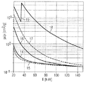
図6は異なった管電圧についての水厚さに依存した散乱対1次の割合が描かれているダイアグラムを示し、
図7は散乱放射補正方法の流れ図を示し、
図8は単位面積質量画像の再構成を示すための仮想ファントムの断面図を示し、
図9は図8の仮想ファントムの平面図を示し、
図10は図8および図9のファントムの低エネルギーX線撮影のシミュレーションを示し、
図11は図8および図9のファントムの高エネルギーX線撮影のシミュレーションを示し、
図12は図8および図9の仮想ファントムの図10および図11のX線画像に基づいて再構成された軟部画像を示し、
図13は図8および図9の仮想ファントムの図10および図11のX線画像に基づいて再構成された骨画像を示す。
FIG. 1 shows an apparatus for double X-ray absorption.
FIG. 2 shows two photon spectra acquired at different tube voltages for an X-ray tube with an anode made of tungsten,
FIG. 3 shows the transition of mass attenuation coefficient depending on photon energy for various body components,
FIG. 4 shows an attenuated image having a non-uniform image range and a uniform image range,
FIG. 5 shows a diagram specifically illustrating the dependence of scattered radiation intensity on different material combinations,
FIG. 6 shows a diagram depicting the ratio of scattering versus first order depending on the water thickness for different tube voltages,
FIG. 7 shows a flow chart of the scattered radiation correction method,
FIG. 8 shows a cross-sectional view of a virtual phantom to show the reconstruction of a unit area mass image,
FIG. 9 shows a plan view of the virtual phantom of FIG.
FIG. 10 shows a simulation of the low energy X-ray imaging of the phantom of FIGS.
FIG. 11 shows a simulation of high energy X-ray imaging of the phantom of FIGS.
FIG. 12 shows a soft part image reconstructed based on the X-ray images of FIGS. 10 and 11 of the virtual phantom of FIGS.
FIG. 13 shows a bone image reconstructed based on the X-ray images of FIGS. 10 and 11 of the virtual phantom of FIGS.
図1は、二重X線吸収法のX線撮影を実施することができるX線装置1を示す。X線装置1はX線管2を含み、X線管2はフィラメントによって形成された陰極3を有する。フィラメント3は加熱電流Iにより加熱される。その際に陰極3から電子が放出され、電子は管電圧Uにより陽極4の方向に加速される。それによって電子線5が生じ、電子線5は陽極4上の焦点に当たる。陽極4において制動された電子はX線放射6を発生する。X線放射6は低エネルギー部分の抑制のために先ずスペクトルフィルタ作用を有する前置フィルタ7を走り抜ける。前置フィルタ7は、一般に、X線放射6のビーム経路内に異なる厚さで挿入される薄い銅板である。引続いて、X線放射6は検査すべき患者8を透過する。
FIG. 1 shows an
患者8を通り抜けたX線放射6が、患者8の減弱画像を記録するX線検出器9によって検出される。その際に、患者8内においてX線放射6を減弱させる物質の構造がX線検出器9に投影される。したがって、減弱画像を含んでいるX線撮影画像は投影画像とも呼ばれる。
X線検出器9は、ディジタルX線画像を作成することのできる多数の検出素子を有する半導体を基礎とする平面型画像検出器または平面型検出器であると好ましい。検出素子はそれぞれ1つの画素を受け入れ、ピクセルとも呼ばれる。
The
X線検出器9の後には評価ユニット10が接続されている。評価ユニット10は、一般に管電圧Uおよび前置フィルタの変化によってX線放射6の異なるエネルギー範囲で撮影される減弱画像の線形結合を形成する。異なるエネルギー範囲で撮影された減弱画像の線形結合によって作成された結合画像は表示ユニット11に表示される。
An
減弱画像の線形結合は、例えば患者8の骨構造が結合画像から消去される差の形成である。このようにして作成された結合画像は軟部組織の減弱構造を含み、このことは特に肺の検査において有利である。 A linear combination of attenuated images is, for example, the formation of a difference in which the bone structure of the patient 8 is erased from the combined image. The combined image created in this way includes soft tissue attenuation structures, which is particularly advantageous in lung examination.
異なるエネルギー範囲での減弱画像の撮影のために、特に管電圧Uおよび前置フィルタ7が変化させられる。低エネルギーでの減弱画像のためには、例えば低い管電圧Uが使用される。更に、前置フィルタ7が僅かの材料厚みを有するので、X線管2から発生されたスペクトルの低エネルギー部分はほんの僅かしか抑制されない。これに対して、高エネルギーでの減弱画像については高い管電圧Uが使用される。更に、とりわけX線管2から発生されたX線スペクトルの高エネルギー部分を通過させる大きな材料厚みを有する前置フィルタ7が使用される。
In particular, the tube voltage U and the prefilter 7 are varied for taking attenuated images in different energy ranges. For low energy attenuated images, for example, a low tube voltage U is used. Furthermore, since the prefilter 7 has a small material thickness, only a small amount of the low energy part of the spectrum generated from the
以下において単位面積質量(単位面積当り質量)を減弱画像に基づいて十分正確に決定することを可能にする方法を説明する。 In the following, a method that makes it possible to determine the unit area mass (mass per unit area) sufficiently accurately based on the attenuation image will be described.
散乱放射補正は結合画像の有用性にとって重要であるので、以下においては、特に散乱放射作用を低減させる方法も説明する。 Since scattered radiation correction is important for the usefulness of the combined image, the following also describes a method for reducing scattered radiation effects in particular.
1.問題提起
患者8を透過するX線放射6の信号形成は、主として放出スペクトルQU(E)、すなわち陽極での制動放射として放出される光子の、印加される管電圧Uに依存したエネルギースペクトルと、使用されるスペクトルフィルタの透過度TF(E)およびX線検出器9のスペクトル応答感度ηD(E)とによって決定される。
1. The signal formation of the
結果として生じる有効正規化スペクトル分布W(E;U)は、
![]()
![]()
管電圧60kV,120kVに相当する2つの有効スペクトル分布についての例が図2に示されている。図2には、keV単位での光子エネルギーEに対する1keV間隔当たりの相対的な光子発生量Nrel/NTが描かれている。ただし、NTは光子の総数である。X線スペクトル12は70kVの管電圧に対応し、X線スペクトル13は120kVの管電圧に対応する。
An example of two effective spectral distributions corresponding to tube voltages of 60 kV and 120 kV is shown in FIG. FIG. 2 shows the relative photon generation amount N rel / N T per 1 keV interval with respect to the photon energy E in keV. Where N T is the total number of photons. The
光子エネルギーEへの水の質量減弱係数(μ/ρ)(E)の依存性が図3に示されている。水の質量減弱曲線14は、血液が水よりも大きい密度ρを有するにもかかわらず、血液の質量減弱曲線とほぼ完全に等しい。これに対して脂肪組織は、質量減弱曲線14とは僅かに相違する質量減弱曲線15を有する。他の質量減弱曲線16は骨組織の質量減弱係数の推移を示す。更に別の質量減弱曲線17,18はカルシウムおよびよう素の質量減弱係数の推移を描く。よう素の質量減弱曲線18は33.2keVの光子エネルギーにおいてKエッジ19を有する。よう素はしばしば造影剤として使用される。
The dependence of water mass attenuation coefficient (μ / ρ) (E) on photon energy E is shown in FIG. The water
図3に基づいて骨物質がX線放射を軟部組織よりも強く吸収することが明白となる。しかしながら、X線放射の減弱係数は、骨組織の場合、高いエネルギーのところで軟部組織の吸収よりも強く低下する。それから、1次放射関数は単色X線放射の使用時にもX線放射エネルギーに関して比例しないことが分かる。それゆえ、異なるエネルギー範囲で撮影された減弱画像に基づいて、骨組織および軟部組織の単位面積質量画像を求めることができる。同様に水の質量減弱曲線14と脂肪組織の質量減弱曲線15との異なるエネルギー依存性に基づいて水と脂肪とを分離することができる。
Based on FIG. 3, it becomes clear that bone material absorbs X-ray radiation more strongly than soft tissue. However, the attenuation factor of X-ray radiation is much lower in bone tissue than at soft tissue absorption at high energy. It can then be seen that the primary radiation function is not proportional with respect to the X-ray radiation energy even when using monochromatic X-ray radiation. Therefore, unit area mass images of bone tissue and soft tissue can be obtained based on attenuation images taken in different energy ranges. Similarly, water and fat can be separated based on the different energy dependence of the
図4には、例えば均一な画像範囲21および不均一な画像範囲22を有する減弱画像20が示されている。均一な画像範囲21においては、専ら減弱係数の均一のエネルギー依存性を有する組織、例えば軟部組織が写像される。これに対して、不均一な画像範囲22においては、減弱係数の異なるエネルギー依存性を有する異なる種類の組織、例えば軟部組織も骨組織も写像される。均一な画像範囲21にも不均一な画像範囲22にも及ぶ減弱画像に基づいて、今や軟部組織および骨組織の単位面積質量画像を作成することができる。散乱放射補正が減弱画像全体にわたって実行されることは必ずしも必要ではない。散乱放射補正は、例えば均一な画像範囲21にある補正範囲23において、または不均一な画像範囲22に配置されている補正範囲24において実行されるとよい。
FIG. 4 shows an
しかしながら、不均一な対象領域に割り当てられている補正範囲24において、散乱放射の補正は厄介である。なぜならば、X線放射の等しい減弱ですら、すなわち等しく正規化された1次強度P1またはP2ですら、散乱放射がビーム経路における物質組成、すなわち両物質の単位面積質量(単位面積当り質量)b1,b2に依存するからである。これについての例が図5に示されている。
However, correction of scattered radiation is cumbersome in the
図5には、同じ1次放射の場合における物質組成への散乱放射の依存性を示すモンテカルロシミュレーションの結果が示されている。管電圧としてU=70kVの電圧が仮定された。間隙の幅は20cmに設定された。X線検出器9の面積は40×30cm2に設定された。シミュレーションは、その都度等しい1次放射曲線25が生じるまで行なわれた。減弱されない放射が先ず5cmの厚みを有する骨物質からなる円板を通り抜け、引続いて20cmの厚みの水を通り抜ける際に、散乱放射分布26が生じる。これに対して、25cmの厚みの骨なしの均一な水円板が通り抜けられる際に、散乱放射分布27が生じる。1次放射曲線25ならびに散乱放射分布26,27は、中央の検出器行の座標xdに対して任意の単位で描かれている。散乱放射分布26,27はそれぞれ同じ目盛で示されている。
FIG. 5 shows the results of Monte Carlo simulation showing the dependence of scattered radiation on the material composition in the case of the same primary radiation. A tube voltage of U = 70 kV was assumed. The width of the gap was set to 20 cm. The area of the
図5に基づいて、散乱放射分布が、存在する物質組成に依存することが明白となる。したがって、測定された投影画像を散乱放射に関して補正することができるようにするためには、個々の物質の単位面積質量(単位面積当り質量)を知っていることが必要である。 Based on FIG. 5, it becomes clear that the scattered radiation distribution depends on the material composition present. Therefore, it is necessary to know the unit area mass (mass per unit area) of an individual substance so that the measured projection image can be corrected for scattered radiation.
以下において、2つの異なる管電圧U1,U2が採用され、かつ場合によっては異なる管側フィルタまたは検出器側フィルタが採用されて、同一の対象についての2つの測定値が考察される。有効スペクトル分布が、
![]()
![]()
ディジタルX線検出器9において全て普通の較正補正が行なわれているものと仮定する。詳細には、それは暗画像減算とピクセルの異なる感度の補正とである。更に正しいI0正規化が行なわれているものと仮定する。I0正規化とは次のことであると理解すべきである。すなわち、減弱対象なしに全く減弱されていない強度が両スペクトルについて規定され、X線検出器9の各ピクセルにおける各強度測定値が相応のI0値による割算によって正規化されることである。以下の説明は、1次放射強度値にせよ、散乱放射強度値にせよ、あるいは1次放射および散乱放射の和からなる測定される全放射強度値にせよ、これらを常に正規化された強度値として扱う。
Assume that all normal calibration corrections have been made in the
以下の説明において次の関係が使用される。
I1,I2 スペクトルW1(E)またはW2(E)における正規化された測定全強度
P1,P2 正規化された当初は未知の1次強度
S1,S2 正規化された当初は未知の散乱放射強度
The following relationship is used in the following description.
Normalized measured total intensity P 1 , P 2 normalized in the I 1 , I 2 spectrum W 1 (E) or W 2 (E) was normalized to the initially unknown primary intensity S 1 , S 2 Initially unknown scattered radiation intensity
理論上、均一な組織の場合においてスペクトルW1(E)またはW2(E)における正規化された1次強度(=1次減弱)については、その都度のX線測定ビームが同一の有効経路長X[cm]または単位面積質量X[g/cm2]を通り抜けるときに、

二重X線吸収法の枠内において、2つの物質の定性的な分離が、一般的に次の経験に基づく公式にしたがって行なわれる。
この場合、左辺の変数はグレー値画像であり、経験に基づく係数w1,w2は、視覚的に両物質のできるだけ良好な分離が得られるように選定すべきである。右辺のI1,I2は、高エネルギー強度画像および低エネルギー強度画像における測定された強度である。一般にI1,I2は異なる割合の散乱放射を含んでいる。したがって、経験に基づく係数w1,w2は異なる散乱放射成分に依存する。左辺におけるグレー値画像は当初は物理量ではない。線形結合によって得られるグレー値画像は、はじめのうちは適切な倍率および加算定数により、近似的に選択すべき両物質の擬似的物質厚みとして、例えば軟部組織および骨の物質厚みとして解釈することができる。 In this case, the variable on the left-hand side is a gray value image, and the empirical coefficients w 1 and w 2 should be selected so as to obtain the best possible separation of both substances visually. I 1 and I 2 on the right side are measured intensities in the high energy intensity image and the low energy intensity image. In general, I 1 and I 2 contain different proportions of scattered radiation. Therefore, the empirical coefficients w 1 and w 2 depend on different scattered radiation components. The gray value image on the left side is not a physical quantity at first. The gray value image obtained by linear combination can be initially interpreted as a pseudo material thickness of both materials to be approximately selected, for example, as soft material and bone material thickness, with appropriate magnification and addition constants. it can.
そこで以下においては、減弱画像から十分正確に個々の成分に基づいて分離される単位面積質量画像が作成され、しかも散乱放射作用が消去される方法を説明する。 Therefore, in the following, a method will be described in which a unit area mass image separated from the attenuated image based on the individual components with sufficient accuracy is created and the scattered radiation action is eliminated.
2.不均一の画像範囲における散乱放射補正の一般的な手順
以下において詳細に説明する方法では、一般的に次の3つの手順が実行される。
2. General procedure for correcting scattered radiation in a non-uniform image range In the method described in detail below, the following three procedures are generally performed.
2.1 逆変換
第1の手順により、両スペクトルについての予め与えられた正規化された1次強度値のペアP1,P2から、分離すべき両物質、例えば軟部組織および骨の対応する単位面積質量密度b1,b2が算出される。正規化は、測定された強度値I1,I2を、対応する減弱されていない強度値I1。0,I2。0によって割算することによって行なわれる。この手順は、
![]()
![]()
2.2 散乱放射の評価
更に、第2の手順が実行される。この第2の手順により、両スペクトルでの予め与えられた空間的な1次強度分布P1(x,y),P2(x,y)および/または分離すべき両物質の求められた空間的な単位面積質量密度分布b1(x,y),b2(x,y)から、両スペクトルについての散乱強度分布S1(x,y),S2(x,y)を算出することができる。この手順は、
![]()
![]()
第2の手順に関しては、文献「ZELLERHOFF,M.;SCHOLZ,B.;RUEHRNSCHOPF,E.−P.;BRUNNER,T.:“Low contrast 3D reconstruction from C−arm data”:Proceedings of SPIE.Medical Imaging,2005,Vol.5745,pp.646−655」に開示された如き畳み込みモデルの拡張が考慮の対象となる。この種の畳み込みモデルは比較的高速のアルゴリズムとして実現される。そのほかに今日の標準コンピュータによってもなおも時間のかかるモンテカルロシミュレーションも考慮の対象となる。両選択肢は具体的な実施例に関連して段落4.1および4.2において更に詳細に説明する。 Regarding the second procedure, the literature “ZELLERHOFF, M .; SCHOLZ, B .; RUEHRRNSCHOPF, E.-P .; , 2005, Vol. 5745, pp. 646-655 ”is considered for the extension of the convolution model. This type of convolution model is implemented as a relatively fast algorithm. In addition, Monte Carlo simulations, which still take time with today's standard computers, are also considered. Both options are described in more detail in paragraphs 4.1 and 4.2 in connection with specific examples.
2.3 散乱放射補正
第3の手順として、散乱ビーム補正アルゴリズムが、
![]()
![]()
![]()
![]()
3.反復法
方程式(#1),(#2),(#3)は反復法により解かれる。反復アルゴリズムは3つの部分、すなわち、予め定められた初期値による反復開始と、初期値が変化させられる反復規則と、中断条件とからなる。
3. The iterative equation (# 1), (# 2), (# 3) is solved by an iterative method. The iterative algorithm consists of three parts: an iterative start with a predetermined initial value, an iterative rule whose initial value is changed, and an interruption condition.
上述の3つの手順により、今や二重X線吸収法の枠内において2つの成分に適用される次の反復法を実行することができる。 With the above three procedures, it is now possible to carry out the next iterative method applied to the two components within the framework of the double X-ray absorption method.
3.1 反復開始
先ず、両スペクトルの測定された強度分布I1(x,y),I2(x,y)および減弱されない放射における強度I1.0,I2.0のみが、与えられた強度分布として受け取られる。散乱放射は未だ分かっていないために、補正されていない正規化された強度分布を初期値として設定する。すなわち、
3.2 反復規則
反復規則はインデックスn(n≧0)を有する反復からインデックスn+1を有する次の反復への移行を決定する。以下において、ピクセル座標(x,y)を省略する。この場合に、2次元関数に関係することに注意を払うべきである。
3.3 反復中断
3.2 Iteration rule The iteration rule determines the transition from the iteration with index n (n ≧ 0) to the next iteration with
3.3 Repeated interruption
反復シリーズは、相前後する反復の間における変化が予め与えられる小さな閾よりも小さい場合に中断される。たいていの場合に、特に比較的小さい中くらいまでの散乱成分(S≦P)の場合に、一般に3回までの反復で十分である。実行すべき反復の最大回数を固定的に設定しても、または比S/Pに依存して設定してもよい。 The iteration series is interrupted when the change between successive iterations is less than a pre-given small threshold. In most cases, up to three iterations are generally sufficient, especially in the case of relatively small intermediate scattering components (S ≦ P). The maximum number of iterations to be performed may be set fixedly or may be set depending on the ratio S / P.
4.実行すべき動作に対する説明
2項において重要な数学的動作式を説明したが、一般論で形式的であり、まだ具体的に説明していない。ここでそれの細部の動作および変形を説明する。
4). Explanations on the operations to be performed In the second paragraph, important mathematical equations have been described, but they are formal in general and have not yet been specifically described. The detailed operation and modification of it will now be described.
4.1 M -1 :二重エネルギー投影データから単位面積当り物質の計算
基本的には、スペクトルW1(E),W2(E)における正規化された1次強度に関して、質量減弱係数α1(E)=(μ1/ρ1)(E),α2(E)=(μ2/ρ2)(E)を有する2つの放射線学的に異なる物質の場合に、X線ビームが透過する単位面積質量密度b 1 ,b 2 [g/cm 2 ]に依存して、
有効スペクトルW1(E),W2(E)は既知として仮定することができ、有効スペクトルW1(E),W2(E)はX線管2の放出スペクトル、スペクトルフィルタの作用およびエネルギーに依存する検出器応答感度を含んでいる。図2において2つの典型的なスペクトル12,13が示され、図3にエネルギーに依存する質量減弱係数が示されている。
The effective spectra W 1 (E) and W 2 (E) can be assumed to be known, and the effective spectra W 1 (E) and W 2 (E) are the emission spectrum of the
1次強度を記述する関数M1(b),M2(b)は原理的に単位面積質量厚さb=(b1,b2)の関数として予め算出可能であり、または実験的に決定可能である。それらは、少なくとも医療診断学において関心のあるエネルギー範囲および物質において、両変数b1,b2に関して部分的に厳密に単調に低下することから、ベクトル演算Mが逆変換させられる。逆変換は、数値計算の標準方法、例えばベクトル関数のためのニュートン−ラフソン法により行なわれる。この種の方法は、例えば「PRESS,FLANNERY,TEUKOLSKY,VETTERLING:“Numerical Recipes.The Art of Scientific Programming”,Cambridge University Press,1989,pp.268−273」に記載されている。 The functions M 1 ( b ) and M 2 ( b ) describing the primary intensity can be calculated in advance as a function of unit area mass thickness b = (b 1 , b 2 ) in principle, or determined experimentally. Is possible. Since they are partly strictly monotonically reduced for both variables b 1 and b 2 at least in the energy range and materials of interest in medical diagnostics, the vector operation M is inverted. The inverse transformation is performed by a standard method of numerical calculation, for example, a Newton-Raphson method for a vector function. This type of method is described in, for example, “PRESS, FLANNERY, TEUKOLSKY, VETTERLING:“ Numeral Recipes. The Art of Scientific Programming ", Cambridge University Press, 1989, pp. 268-273".
ここで述べておくに、逆変換のためには方程式(#6a,b)の右辺において対数計算をするのが有利である。 Here, it is advantageous to perform logarithmic calculation on the right side of the equation (# 6a, b) for the inverse transformation.
更に、述べておくに、少なくとも反復開始時に逆変換が一方(または両方)の単位面積質量厚さに関して物理的な定義範囲外でしか満たされない場合が発生し得る。なぜならば、1次強度P1,P2の補正された評価がまだ不正確な散乱放射補正のためにまだ誤差を含んでいるからである。逆変換M-1が正規化された測定値P1,P2の発生した値範囲全体において計算されるべきである場合、ベクトル関数は式(#7)にしたがってb1,b2の物理的な定義範囲を相応に越えて、特に仮定の負の単位面積質量厚さについても計算されなければならない。 Furthermore, it should be noted that at least at the beginning of an iteration, the case can occur where the inverse transformation is only fulfilled outside the physical definition range for one (or both) unit area mass thickness. This is because the corrected evaluation of the primary intensities P 1 and P 2 still contains errors due to inaccurate scattered radiation correction. If the inverse transform M −1 is to be calculated over the entire generated value range of normalized measurements P 1 , P 2 , the vector function is the physical of b 1 , b 2 according to equation (# 7) Beyond this definition range, the hypothetical negative unit area mass thickness must also be calculated.
4.2 S estim :散乱放射分布の評価モデル
散乱放射分布の決定のために、例えば既に述べた畳み込みモデルの一般化またはモンテカルロ法を使用することができる。
4.2 S estim : Evaluation model of the scattered radiation distribution For the determination of the scattered radiation distribution, for example, the generalization of the convolution model already described or the Monte Carlo method can be used.
両方法は、散乱放射と、両物質成分、たいていは水および骨の単位面積質量密度とを決定するために、測定された全強度内に含まれる情報を使用することができる。 Both methods can use the information contained within the total measured intensity to determine the scattered radiation and both material components, mostly water and bone unit area mass density.
4.2.1 一般化された畳み込みモデルによる散乱放射決定
文献「ZELLERHOFF,M.;SCHOLZ,B.;RUEHRNSCHOPF,E.−P.;BRUNNER,T.:“Low constant 3D reconstruction from C−arm data.”:Proceedings of SPIE.Medical Imaging,2005,Vol.5745,pp.646−655」に基づく畳み込みモデルの場合には、散乱放射分布が次の数式、すなわち
![]()
![]()
G(x,y)は散乱放射伝搬によって生じさせられる低域通過フィルタ作用(ぼけ)を経験に基づいて記述する2次元の畳み込み核である。 G (x, y) is a two-dimensional convolution kernel that describes, based on experience, a low-pass filter action (blur) caused by the propagation of scattered radiation.
C(p)は、較正する重み関数であり、
![]()
![]()
更に、Cは物理的な取得パラメータに依存する。すなわち、電圧U、放射フィルタ、検出器のコリメータ領域サイズFyz、散乱放射線除去用グリッド、間隙等である。 Furthermore, C depends on the physical acquisition parameters. That is, voltage U, radiation filter, detector collimator region size F yz , scattered radiation removal grid, gap, and the like.
Cは、モンテカルロ計算により予め算出可能であり、テーブルとして記憶可能である。固定の取得パラメータの場合、Cは1つの変数、すなわち水等価の層厚さb0(p)にのみ依存する。2つの撮影が異なる管電圧において2つの異なるエネルギースペクトルにより行なわれることから、2つのテーブルC1,C2が必要である。 C can be calculated in advance by Monte Carlo calculation and can be stored as a table. For a fixed acquisition parameter, C depends only on one variable, the water equivalent layer thickness b 0 (p). Two tables C 1 and C 2 are required because the two radiographs are performed with two different energy spectra at different tube voltages.
2つの典型的なテーブルが図6にグラフで示されている。 Two typical tables are shown graphically in FIG.
図6において、割合曲線28はU=60kVの管電圧および0.1mmの銅を有する前置フィルタの場合における1次強度に対する散乱強度の割合C1を与え、割合曲線29はU=120kVの管電圧および0.3mmの銅を有する前置フィルタの場合における1次強度に対する散乱強度の割合C2を与える。
In FIG. 6, the
式(#9a)における重み関数により、式(#5a−c)における反復ループ内における簡単化された散乱放射補正が得られる。評価された1次放射P1,P2から導き出された水等価の経路長およびこれから再びテーブルCを介する散乱割合S/Pが使用されて反復的に改善される。 The weight function in equation (# 9a) provides a simplified scattered radiation correction within the iterative loop in equation (# 5a-c). The water equivalent path length derived from the estimated primary radiation P 1 , P 2 and the scattering ratio S / P again through the table C are then used to improve iteratively.
ここに記載の公知の数式の一般化は、異なる電圧U1,U2および場合によっては前置フィルタ処理に応じた両スペクトルのためのテーブルC1,C2が、1つの変数、すなわち水層厚さだけでなく、2つの変数b1,b2、すなわち水厚さおよび骨厚さにも依存して作成されることにある。
両物質厚さb1,b2の現在値が各反復ステップにおいて新たに得られる。物質厚さb1,b2の新たな値は、反復的に改善される散乱放射評価を得るために、今や両パラメータb1,b2に依存するテーブルC1,C2への新たな入力値として使用することができる。 The current values of both material thicknesses b 1 and b 2 are obtained anew at each iteration step. The new values of the material thickness b 1 , b 2 are now a new input to the tables C 1 , C 2 which now depend on both parameters b 1 , b 2 in order to obtain an iteratively improved scattered radiation estimate. Can be used as a value.
pまたはPへの明白な依存性はもはや現われない。これはb1,b2への依存性によって置き換えられる。 The obvious dependence on p or P no longer appears. This is replaced by the dependency on b 1 and b 2 .
4.2.2 モンテカルロ法による散乱放射決定
基本的には、各反復ステップにおいて新たに評価される現在の両物質厚さ分布b1(x,y),b2(x,y)対する散乱放射分布を直接的にモンテカルロ法により算出することも考えられ得る。もちろん、モンテカルロシミュレーションは非常に計算費用がかかるので、モンテカルロ法の使用は高い計算能力を必要とする。
4.2.2 Determination of scattered radiation by the Monte Carlo method Basically, the scattered radiation for both current material thickness distributions b 1 (x, y), b 2 (x, y) to be newly evaluated at each iteration step. It is also conceivable to calculate the distribution directly by the Monte Carlo method. Of course, since the Monte Carlo simulation is very computationally expensive, the use of the Monte Carlo method requires high computational power.
4.3 S korr :散乱放射補正アルゴリズム
散乱放射補正は、減算によっても乗算によって行なうことができる。この場合にそれぞれ2つのスペクトルを補正することができる。
4.3 S korr : Scattering Radiation Correction Algorithm Scattering radiation correction can be performed by multiplication also by subtraction. In this case, each of the two spectra can be corrected.
減算による散乱放射補正は、特に簡単であり、それぞれの補正されていない正規化された強度分布から、評価された散乱強度を減算することである。
ついては、
I1'(x,y)=I1(x,y)/I1.0
I2'(x,y)=I2(x,y)/I2.0
が当てはまる。
Scattering radiation correction by subtraction is particularly simple: subtracting the estimated scattering intensity from each uncorrected normalized intensity distribution.
I 1 '(x, y) = I 1 (x, y) / I 1.0
I 2 '(x, y) = I 2 (x, y) / I 2.0
Is true.
一定値は非常に大まかな近似にすぎないので、式(#5)において減算時に負の値が発生することが起こり得る。このような物理的に意味のない値はできるだけ防止されるべきである。対抗措置は、式(#10a)における減算による補正の代わりに、乗算による散乱放射補正を使用することである。
S1 (n)(x,y)<<I1(x,y)およびS2 (n)(x,y)<<I2(x,y)
の場合に関しては、式(#10b)に従う乗算による補正は式(#10a)に従う減算による補正に移行する。
S 1 (n) (x, y) << I 1 (x, y) and S 2 (n) (x, y) << I 2 (x, y)
In this case, the correction by multiplication according to the equation (# 10b) shifts to the correction by subtraction according to the equation (# 10a).
5. 位置依存性
散乱放射の空間的な分布は、ノイズは別として一般に平らであり、したがって低周波数である。これは、検出器面上の非常に僅かな個所における散乱放射を個々の点ごとにまたは関心範囲において決定することで十分であることを意味する。したがって、最も簡単な近似は2次放射強度についての適切な一定の平均値である。
5. The spatial distribution of position-dependent scattered radiation is generally flat apart from noise and is therefore low frequency. This means that it is sufficient to determine the scattered radiation at very few points on the detector plane for each individual point or in the area of interest. Thus, the simplest approximation is a suitable constant average value for the secondary radiation intensity.
平均の散乱放射背景強度の総括的な評価のためには、図4にしたがって適切な関心のある補正範囲23または24を選択し、低エネルギーの投影画像および高エネルギーの投影画像についてこの関心範囲にわたるそれぞれ1つの平均値を形成することで十分である。この値対I- 1,I- 2(“I- 1,I- 2”において“−”は“I”の上に付されたバ
ーを示す)について、散乱放射強度の対応する値対S- 1,S- 2(“S- 1,S- 2”において“−”は“S”の上に付されたバーを示す)が反復法によって決定される。ここにおいて使用されるオーバラインは概算された値、平均化された値であること表し、あるいはそれどころか一定値であることさえも表す。
For a comprehensive assessment of the average scattered radiation background intensity, select a
補正範囲23または24の外側における散乱放射補正は、それぞれ補正されていない正規化された強度分布から、評価された散乱放射強度を減算することである。
左辺には補正された1次分布があり、これに対して反復法の終了後に得られる対S- 1,S- 2は散乱放射強度である。(x,y)は検出器におけるピクセル座標を表す。波形記号(〜)は補正されたデータ、すなわち補正に基づく概算であることを示そうとするものである。 There are corrected primary distribution to the left, this pair is obtained after completion of the iterative method with respect to S - 1, S - 2 is a scattered radiation intensity. (X, y) represents pixel coordinates in the detector. The waveform symbol (˜) is intended to indicate corrected data, ie, an approximation based on the correction.
一定値は非常に大まかな近似にすぎないことから、式(#11)において減算時に負の値が発生することが起こり得る。このような物理的に意味のない値はあらゆる場合に防止されなければならない。措置は散乱放射の総括的な決定のために強い減弱の範囲における適切な補正範囲23または24を選択することである。強い減弱を有する範囲は小さなI1,I2値を有する範囲である。
Since the constant value is only a very rough approximation, a negative value may occur during subtraction in equation (# 11). Such physically insignificant values must be prevented in all cases. The measure is to select an
他の措置は、式(#11)における減算による補正の代わりに乗算による散乱放射補正を行なうことである。
S- 1<<J1(x,y)およびS- 2<<J2(x,y)の場合に関して、式(#12)は式(#11)に移行する。 S - 1 << J 1 (x , y) and S - 2 << J 2 (x , y) for the case of formula (# 12) shifts to the formula (# 11).
散乱放射背景の位置依存性は、さらに個々の画素に関連して先に説明した補正方法を検出器における関心範囲または走査点の一様な粗いラスタに適用し、結果を粗いラスタの補間により本来の微細なピクセルラスタに拡張することによって処理される。式(#10),(#11)による補正は同じように拡張することができる。その場合S- 1,S- 2はもはや定数ではなく、ピクセル座標(x,y)に依存した関数である(たとえこの依存性が一般に僅かのみであったとしても)。 The position dependence of the scattered radiation background is further improved by applying the correction method described above in relation to the individual pixels to a uniform coarse raster of the area of interest or scan point in the detector, and the result is essentially interpolated by the coarse raster. By extending to a fine pixel raster. The correction according to equations (# 10) and (# 11) can be extended in the same way. In that case S - 1, S - 2 is no longer constant, the pixel coordinates (x, y) is a function that depends on (even if this dependency was only generally slightly).
更に、位置依存性は、個々の画素または関心範囲について説明した方法が検出器における関心範囲または走査点の一様な粗いラスタに適用されることによって把握される。それから、粗いラスタにおいて求められた散乱放射成分の値が広い分布関数により畳み込み処理をすることによって、本来の微細なラスタへの補間が行なわれる。 Furthermore, position dependence is perceived by applying the method described for individual pixels or regions of interest to a uniform coarse raster of the region of interest or scan points at the detector. Then, convolution processing is performed with a distribution function having a wide scattered radiation component value obtained in a coarse raster, whereby interpolation into an original fine raster is performed.
平滑する畳み込み演算による従来の補正方法も、散乱放射が空間的に低周波であるという事情を考慮する。該当する方法は、文献「ZELLERHOFF,M.;SCHOLZ,B.;RUEHRNSCHOPF,E.−P.;BRUNNER,T.:“Low contrast 3D reconstruction from C−arm data.”:Proceedings of SPIE.Medical Imaging,2005,Vol.5745,pp.646−655」に記載されている。ここに記載されている数式とそのような比較的高価な畳み込みモデルとの組み合わせが基本的には可能である。例えば、ここに記載されている方法の1つによって、かつそれに並行して従来の方法を用いて、散乱放射成分が決定され、その結果が平均化されるとよい。 The conventional correction method by the smoothing convolution operation also takes into account the fact that the scattered radiation is spatially low frequency. The relevant method is described in the literature “ZELLERHOFF, M .; SCHOLZ, B .; RUEHRRNSCHOPF, E.-P .; BRUNNER, T .:“ Low contrast 3D reconstruction from C-arm data. ": Proceedings of SPIE. Medical Imaging, 2005, Vol. 5745, pp. 646-655". A combination of the mathematical formula described here and such a relatively expensive convolution model is basically possible. For example, the scattered radiation components may be determined and averaged by one of the methods described herein and using conventional methods in parallel.
6.方法経過
ここに記載されている散乱放射補正方法はそれぞれ、検査対象の少なくとも近似的に決定された3次元ボリューム画像を用いることなく減弱画像に基づいて散乱放射成分を決定する再現可能な方法である。本方法においては、むしろ、異なるエネルギー範囲において撮影された減弱画像によって用いることのできる付加的な情報が散乱放射成分を評価するために使用される。
6). Methodology Each of the scattered radiation correction methods described herein is a reproducible method for determining the scattered radiation component based on the attenuated image without using at least an approximately determined three-dimensional volume image of the object to be examined. . Rather, in this method, additional information that can be used by attenuated images taken at different energy ranges is used to evaluate the scattered radiation component.
図7は方法の流れ図を示す。 FIG. 7 shows a flow chart of the method.
この方法は値の割り当て30から始まり、これに式(#1)による逆変換31が行なわれる。その際に多次元の単位面積質量について特徴的な量が得られ、それらの量に基づいて式(#2)による評価を実行することができる。続いて、式(#3)による1次放射成分のための初期値の補正33が行なわれる。最後に質問34により、逆変換31が補正された1次放射成分により繰り返されるかどうかが決定される。
This method starts with a
7.簡単化された方法
これまでに説明した方法のほかに、個々の減弱画像についてそれぞれ個別の散乱放射補正を行ない、その後得られた1次放射強度に基づいて式(#1)による逆変換を行なうことも可能である。例えば、低エネルギー減弱画像および高エネルギー減弱画像についてそれぞれ1つの空間的な低周波の散乱放射分布が決定されて、低エネルギー減弱画像または高エネルギー減弱画像の減弱値から差し引かれるとよい。
7). Simplified method In addition to the method described so far, individual scattered radiation correction is performed for each attenuated image, and then the inverse transformation is performed by the formula (# 1) based on the obtained primary radiation intensity. It is also possible. For example, one spatial low frequency scattered radiation distribution for each of the low energy attenuated image and the high energy attenuated image may be determined and subtracted from the attenuation value of the low energy attenuated image or the high energy attenuated image.
2次放射成分の決定は測定技術的にはビームストップ法または計算法によって行なわれる。ビームストップ法は2つの付加的な測定を必要とする欠点を有する。これらの測定は、もちろん、ノイズは別として散乱放射分布の低周波の性質ゆえに、非常に僅かな線量および僅かな付加的なX線被爆で行なわれるとよい。2次放射成分が公知の計算法により行なわれる場合、患者での付加的な測定を行なう必要がない。公知の散乱放射補正方法はリアルタイムで実施可能であるが、場合によっては予めシステム開発の枠内において測定またはモンテカルロシミュレーションによって作成されなければならないデータベースへのアクセスを必要とする。 The determination of the secondary radiation component is performed in terms of measurement technology by the beam stop method or the calculation method. The beam stop method has the disadvantage of requiring two additional measurements. These measurements, of course, should be performed with very little dose and few additional x-ray exposures due to the low frequency nature of the scattered radiation distribution apart from noise. If the secondary radiation component is performed by known calculation methods, there is no need to make additional measurements on the patient. The known scattered radiation correction method can be implemented in real time, but in some cases requires access to a database that must be created beforehand by measurement or Monte Carlo simulation within the framework of system development.
ひき続く式(#1)による逆変換は一般に解析的には行なわれなくてよい。これに対して、既述のニュートン−ラフソン法による数値的逆変換は一般的に可能である。逆変換は、予め行なってテーブルの形で記憶させることもできるので、具体的な適用例において式(#1)の処理は処理テーブルでの検索によって置き換えることができる。 The inverse transformation by the following equation (# 1) generally does not need to be performed analytically. On the other hand, numerical inversion by the Newton-Raphson method described above is generally possible. Since the inverse transformation can be performed in advance and stored in the form of a table, in the specific application example, the processing of the formula (# 1) can be replaced by a search in the processing table.
8.デモンストレーション例
図8ないし図13に基づいて、減弱画像からの単位面積質量画像の再構成を具体的に示す医用画像化の例を説明する。
8). Demonstration Example Based on FIGS. 8 to 13, an example of medical imaging that specifically shows the reconstruction of a unit area mass image from an attenuated image will be described.
二重X線吸収法についての典型的な適用例は、肺結節を検出することを可能にするための胸部撮影または肺撮影における軟部組織と骨組織との分離である。 A typical application for dual x-ray absorption is the separation of soft and bone tissue in chest or lung imaging to allow detection of lung nodules.
この場合に方法はファントム35に基づいて開始される。図8はファントム35の横断面を示し、これに対して図9はファントム35の平面図を示す。
In this case, the method starts based on the
ファントム35は直方体形状の軟部組織36を含み、軟部組織36上に中間に配置された直方体形状の腫瘍組織37が存在し、腫瘍組織37は同様に軟部組織からなる。軟部組織36の半分の上方に骨組織38が広がり、骨組織38も腫瘍組織37を半分まで覆っている。
The
図10には低エネルギー範囲におけるX線画像39が示されている。低エネルギー範囲におけるX線画像39については、U=60kVの管電圧および0.1mmの厚さの銅の前置フィルタでの撮影がモンテカルロ法によってシミュレーションされた。これに対して、図11は高エネルギー範囲において撮影されたX線画像40を示す。特に、U=120kV管電圧および0.1mmの厚さを有する銅の前置フィルタがシミュレーションされた。X線画像39,40においては、表示可能性のために、異なるグレー値が異なる密度のハッチングによって再現された。この場合に、対応する画像範囲が暗ければ暗いほど、ハッチングの密度がますます大きくなっている。
FIG. 10 shows an
図10および図11には、得られた減弱画像が示されているのに対して、図12および図13は、前述の8項において説明した簡単化された方法により作成された単位面積質量画像を示す。特に図12は軟部画像41を示し、図13は骨画像42を示す。軟部画像41および骨画像42においてもグレー値がハッチング密度によって再現されている。軟部画像41および骨画像42において、軟部画像41または骨画像42が明るければ明るいほど、ビーム経路内にますます多くの物質が存在する。軟部画像41に基づいて、画像半分が骨組織38によって覆われているか否かに関係なく、腫瘍組織37の範囲において明るさがほぼ一定であることが明白に認識可能である。もちろん骨組織38の範囲は軟部画像41においても比較的強い画像ノイズに基づいて認識可能である。これは、特に骨組織38の範囲内の劣った信号雑音比にも起因する。なぜならばX線放射はそこでは強く吸収されるからである。このための除去対策は高いノイズを有する範囲を局所的に強く平滑するノイズ順応性画像フィルタ処理である。
10 and 11 show the attenuated images obtained, whereas FIGS. 12 and 13 show unit area mass images created by the simplified method described in section 8 above. Indicates. In particular, FIG. 12 shows a
9.利点
散乱放射補正を含めた反復サイクルによって物質分離の精度が明白に向上する。
9. Advantages Repeated cycles, including scattered radiation correction, clearly improve the accuracy of material separation.
更に、反復法を含むことにより、反復がなければ用いることのできないであろう2つの物質成分の単位面積質量厚さに関する付加的な情報により散乱放射評価モデルを改良することができることによって、散乱放射補正の改善が可能にされる。特に、軟部組織および骨組織の混在時にも散乱放射補正を行なうことができる。 In addition, by including an iterative method, the scattered radiation evaluation model can be improved with additional information about the unit area mass thickness of the two material components that would otherwise not be available, so that the scattered radiation evaluation model can be improved. An improvement in correction is made possible. In particular, scattered radiation correction can be performed even when soft tissue and bone tissue are mixed.
公式の変数またはパラメータにより記述される基礎をなす物理学的数学モデルのおかげで、計算過程は体系的に可変の範囲条件に対して簡単にパラメータまたはパラメータ関数の変化によって適合可能である。例えばスペクトルの変化は、異なった電圧の選択によって、放射フィルタの変更によって、あるいは撮影ジオメトリの変更によって考慮することができる。 Thanks to the underlying physical mathematical model described by formal variables or parameters, the calculation process can be easily adapted to systematically variable range conditions by changing parameters or parameter functions. For example, spectral changes can be taken into account by selecting different voltages, by changing the radiation filter, or by changing the imaging geometry.
基本的にはここで説明した方法は、分離すべき物質を予め設定する際に多重スペクトル画像化のパラメータを適切な評価尺度に関して最適化する可能性を開く。特に、使用電圧、フィルタの種類および検出器線量が、患者線量に比べた信号雑音比の改善のために指定される。 Basically, the method described here opens up the possibility of optimizing the parameters of the multispectral imaging with respect to a suitable evaluation measure when presetting the substances to be separated. In particular, the working voltage, filter type and detector dose are specified to improve the signal to noise ratio compared to the patient dose.
1 X線装置
2 X線管
3 陰極
4 陽極
5 電子ビーム
6 X線放射
7 前置フィルタ
8 患者
9 X線検出器
10 評価ユニット
11 表示ユニット
12 X線スペクトル(管電圧70kV)
13 X線スペクトル(管電圧120kV)
14 水の質量減弱曲線
15 脂肪組織の質量減弱曲線
16 骨組織の質量減弱曲線
17 カルシウムの質量減弱曲線
18 よう素の質量減弱曲線
19 Kエッジ
20 減弱画像
21 均一な画像範囲
22 不均一な画像範囲
23 補正範囲
24 補正範囲
25 1次放射曲線
26 散乱放射分布
27 散乱放射分布
28 1次強度に対する散乱強度の比率を示す曲線
29 1次強度に対する散乱強度の比率を示す曲線
30 値の割り当て
31 逆変換
32 評価
33 補正
34 質問
35 ファントム
36 軟部組織
37 腫瘍組織
38 骨組織
39 低エネルギー範囲におけるX線画像
40 高エネルギー範囲におけるX線画像
41 軟部画像
42 骨画像
1
13 X-ray spectrum (tube voltage 120kV)
14 Mass attenuation curve of
Claims (15)
放射源(2)により放射(6)が発生され、この放射(6)により検査対象(8)が透視され、
放射(6)により検出装置(9)が作動され、この検出装置(9)によって異なるエネルギー範囲での減弱画像が検出され、
対象(8)内の多次元の単位面積質量を異なるエネルギー範囲において撮影された減弱画像の減弱値に結合する多次元の減弱関数の逆変換により、対象(8)内の単位面積質量が決定され、
決定された単位面積質量に基づいて減弱画像から単位面積質量画像が作成される
単位面積質量画像の作成方法において、
散乱により生じた2次放射成分(26,27)が決定され、減弱画像が2次放射成分(26,27)に関して補正され、
異なるエネルギー範囲において撮影された減弱画像の2次放射成分(26,27)を決定するために、逆減弱関数の計算時に、散乱放射補正を実行される補正画像範囲(23,24)について2次放射成分(26,27)を決定するために使用される単位面積質量と同じ単位面積質量を生じかつ減弱によって発生した1次放射成分(25)に関連づけられている2次放射成分(26,27)が補正画像範囲(23,24)内で探索される
ことを特徴とする単位面積質量画像の作成方法。 A method of creating a unit area mass image based on attenuated images taken in different energy ranges,
More radiation to the radiation source (2) (6) is generated, more inspection target (8) is transparent to the radiation (6),
More detector to the radiation (6) (9) is activated, the attenuation image into the detection device (9) Therefore, in different energy ranges is detected,
The unit area mass in the object (8) is determined by the inverse transformation of the multidimensional attenuation function that combines the multidimensional unit area mass in the object (8) with the attenuation values of the attenuation images taken in different energy ranges. ,
A unit area mass image is created from the attenuated image based on the determined unit area mass.
The secondary radiation component (26, 27) produced by the scattering is determined, the attenuated image is corrected with respect to the secondary radiation component (26, 27) ,
In order to determine the secondary radiation components (26, 27) of the attenuated image taken in different energy ranges, the secondary for the corrected image range (23, 24) for which the scattered radiation correction is performed when calculating the inverse attenuation function. A secondary radiation component (26, 27) that produces the same unit area mass as the unit area mass used to determine the radiation component (26, 27) and is associated with the primary radiation component (25) generated by attenuation. ) Is searched in the corrected image range (23, 24) . A method of creating a unit area mass image.
Applications Claiming Priority (2)
| Application Number | Priority Date | Filing Date | Title |
|---|---|---|---|
| DE102007020065A DE102007020065A1 (en) | 2007-04-27 | 2007-04-27 | Method for the creation of mass occupation images on the basis of attenuation images recorded in different energy ranges |
| DE102007020065.1 | 2007-04-27 |
Publications (3)
| Publication Number | Publication Date |
|---|---|
| JP2008272476A JP2008272476A (en) | 2008-11-13 |
| JP2008272476A5 JP2008272476A5 (en) | 2011-03-10 |
| JP5264268B2 true JP5264268B2 (en) | 2013-08-14 |
Family
ID=39777522
Family Applications (1)
| Application Number | Title | Priority Date | Filing Date |
|---|---|---|---|
| JP2008115604A Expired - Fee Related JP5264268B2 (en) | 2007-04-27 | 2008-04-25 | How to create a unit area mass image |
Country Status (3)
| Country | Link |
|---|---|
| US (1) | US8041096B2 (en) |
| JP (1) | JP5264268B2 (en) |
| DE (1) | DE102007020065A1 (en) |
Families Citing this family (25)
| Publication number | Priority date | Publication date | Assignee | Title |
|---|---|---|---|---|
| DE102005051620A1 (en) * | 2005-10-27 | 2007-05-03 | Siemens Ag | Iterative object tomographic data reconstruction procedure uses back projection of object and applies corrections calculated from difference from forward projection |
| FR2903211B1 (en) * | 2006-06-30 | 2009-03-06 | Gen Electric | METHODS AND DEVICES FOR CORRECTING IMPLANT MAMMOGRAPHY AND SEGMENTING AN IMPLANT |
| DE102007014723A1 (en) * | 2007-03-23 | 2008-11-27 | Gesellschaft für Schwerionenforschung mbH (GSI) | Planning target volume determination method for use in particle therapy system, involves determining target volume equivalent to minimum target volume in fictive homogeneous body, and extending equivalent target volume by a safety margin |
| US8080805B2 (en) * | 2010-03-09 | 2011-12-20 | International Business Machines Corporation | FET radiation monitor |
| KR101486776B1 (en) * | 2010-07-29 | 2015-01-29 | 삼성전자주식회사 | Method and apparatus of processing image and medical image system employing the same |
| US8614111B2 (en) | 2011-07-25 | 2013-12-24 | International Business Machines Corporation | Fully depleted silicon on insulator neutron detector |
| WO2013024890A1 (en) * | 2011-08-18 | 2013-02-21 | 株式会社東芝 | Photon-counting x-ray computed tomography system and scatter correction method |
| US8361829B1 (en) | 2011-08-31 | 2013-01-29 | International Business Machines Corporation | On-chip radiation dosimeter |
| US9101325B2 (en) * | 2012-03-28 | 2015-08-11 | Carestream Health, Inc. | Chest radiography image contrast and exposure dose optimization |
| CN103720482B (en) * | 2012-10-11 | 2016-01-20 | 财团法人工业技术研究院 | Image reconstruction method and system and image construction method and system |
| US9589373B2 (en) * | 2013-02-05 | 2017-03-07 | Carestream Health, Inc. | Monte carlo modeling of field angle-dependent spectra for radiographic imaging systems |
| US9615808B2 (en) * | 2014-05-27 | 2017-04-11 | Koninklijke Philips N.V. | Method and radiography system for grid-like contrast enhancement |
| US10357221B2 (en) * | 2014-08-22 | 2019-07-23 | Samsung Electronics Co., Ltd. | Anatomical imaging system with improved detector calibration process |
| WO2016042466A2 (en) * | 2014-09-15 | 2016-03-24 | Koninklijke Philips N.V. | Iterative image reconstruction with a sharpness driven regularization parameter |
| KR102372165B1 (en) * | 2015-01-22 | 2022-03-11 | 삼성전자주식회사 | X-ray imaging apparatus, image processing apparatus and method for image processing |
| US9993219B2 (en) * | 2015-03-18 | 2018-06-12 | The Board Of Trustees Of The Leland Stanford Junior University | X-ray anti-scatter grid with varying grid ratio |
| US9538975B2 (en) * | 2015-04-08 | 2017-01-10 | Toshiba Medical Systems Corporation | Scatter correction method and apparatus for computed tomography imaging |
| US10859515B2 (en) * | 2016-03-23 | 2020-12-08 | Carl Zeiss X-ray Microscopy, Inc. | Method and system for spectral characterization in computed tomography x-ray microscopy system |
| JP7054329B2 (en) * | 2017-10-06 | 2022-04-13 | キヤノン株式会社 | Image processing equipment, image processing methods and programs |
| CN108281131B (en) * | 2018-01-10 | 2022-04-15 | 常熟市浙大紫金光电技术研究中心 | Full-space active noise suppression device and preparation method thereof |
| JP7093233B2 (en) * | 2018-06-07 | 2022-06-29 | キヤノン株式会社 | Radiography equipment, radiography methods and programs |
| WO2020028896A1 (en) | 2018-08-03 | 2020-02-06 | Neurologica Corporation | Ai-based rendered volume auto-correction for fixed and mobile x-ray imaging modalities and other imaging modalities |
| JP7458750B2 (en) * | 2019-11-13 | 2024-04-01 | キヤノン株式会社 | IMAGE PROCESSING APPARATUS, RADIATION IMAGING APPARATUS, IMAGE PROCESSING METHOD, AND PROGRAM |
| JP7436320B2 (en) * | 2020-07-31 | 2024-02-21 | 富士フイルム株式会社 | Radiographic image processing device, method and program |
| CN113933323A (en) * | 2021-10-15 | 2022-01-14 | 武汉联影生命科学仪器有限公司 | Method for obtaining and applying K-edge identification capability parameter table |
Family Cites Families (22)
| Publication number | Priority date | Publication date | Assignee | Title |
|---|---|---|---|---|
| US4217641A (en) | 1978-04-28 | 1980-08-12 | U.S. Philips Corporation | Correction for polychromatic X-ray distortion in CT images |
| US4247774A (en) * | 1978-06-26 | 1981-01-27 | The United States Of America As Represented By The Department Of Health, Education And Welfare | Simultaneous dual-energy computer assisted tomography |
| US5115394A (en) * | 1983-11-25 | 1992-05-19 | Technicare Corporation | Dual energy computerized tomography system |
| US5164590A (en) * | 1990-01-26 | 1992-11-17 | Mobil Oil Corporation | Method for evaluating core samples from x-ray energy attenuation measurements |
| JPH05161633A (en) * | 1991-12-18 | 1993-06-29 | Toshiba Corp | Radiation diagnostic device |
| JPH0614911A (en) * | 1992-07-02 | 1994-01-25 | Toshiba Corp | X-ray diagnostic method and device therefor |
| EP0660599B2 (en) * | 1993-12-24 | 2002-08-14 | Agfa-Gevaert | Partially-transparent-shield-method for scattered radiation compensation in x-ray imaging |
| DE4410888A1 (en) | 1994-03-29 | 1995-10-05 | Zeiss Carl Jena Gmbh | Apparatus for irradiating human tissue using multi-wavelength IR light |
| DE19523090C1 (en) * | 1995-06-26 | 1996-08-29 | Siemens Ag | Medical X=ray CT investigation appts. |
| US5648997A (en) * | 1995-12-29 | 1997-07-15 | Advanced Optical Technologies, Inc. | Apparatus and method for removing scatter from an x-ray image |
| FR2759800B1 (en) * | 1997-02-17 | 1999-03-26 | Commissariat Energie Atomique | METHOD FOR CORRECTING THE DIFFUSED FLOW IN DIGITAL RADIOGRAPHY IMAGES |
| US6636622B2 (en) * | 1997-10-15 | 2003-10-21 | Wisconsin Alumni Research Foundation | Method and apparatus for calibration of radiation therapy equipment and verification of radiation treatment |
| US6175755B1 (en) * | 1998-06-11 | 2001-01-16 | The University Of British Columbia | Method of lung surface area analysis using computed tomography |
| DE10143131B4 (en) * | 2001-09-03 | 2006-03-09 | Siemens Ag | Method for determining density and atomic number distributions in radiographic examination methods |
| US20030128801A1 (en) * | 2002-01-07 | 2003-07-10 | Multi-Dimensional Imaging, Inc. | Multi-modality apparatus for dynamic anatomical, physiological and molecular imaging |
| US7352887B2 (en) * | 2003-04-11 | 2008-04-01 | Hologic, Inc. | Scatter rejection for composite medical imaging systems |
| US7092485B2 (en) * | 2003-05-27 | 2006-08-15 | Control Screening, Llc | X-ray inspection system for detecting explosives and other contraband |
| DE10347971B3 (en) * | 2003-10-15 | 2005-06-09 | Siemens Ag | Method and device for determining the liquid type of a liquid accumulation in an object |
| US7065234B2 (en) * | 2004-02-23 | 2006-06-20 | General Electric Company | Scatter and beam hardening correction in computed tomography applications |
| DE102004029010A1 (en) * | 2004-06-16 | 2006-01-19 | Siemens Ag | Device and method for scattered radiation correction in projection radiography, in particular mammography |
| JP2006334319A (en) * | 2005-06-06 | 2006-12-14 | Canon Inc | X-ray ct apparatus and method of preprocessing thereof, data preparation device and method thereof, and control program |
| US7469037B2 (en) * | 2007-04-03 | 2008-12-23 | Illinois Institute Of Technology | Method for detecting a mass density image of an object |
-
2007
- 2007-04-27 DE DE102007020065A patent/DE102007020065A1/en not_active Withdrawn
-
2008
- 2008-04-22 US US12/148,791 patent/US8041096B2/en not_active Expired - Fee Related
- 2008-04-25 JP JP2008115604A patent/JP5264268B2/en not_active Expired - Fee Related
Also Published As
| Publication number | Publication date |
|---|---|
| DE102007020065A1 (en) | 2008-10-30 |
| JP2008272476A (en) | 2008-11-13 |
| US20100027867A1 (en) | 2010-02-04 |
| US8041096B2 (en) | 2011-10-18 |
Similar Documents
| Publication | Publication Date | Title |
|---|---|---|
| JP5264268B2 (en) | How to create a unit area mass image | |
| US10235766B2 (en) | Radiographic image analysis device and method, and storage medium having stored therein program | |
| US7551716B2 (en) | Apparatus and method for scatter correction in projection radiography | |
| Rinkel et al. | A new method for x-ray scatter correction: first assessment on a cone-beam CT experimental setup | |
| US7751525B2 (en) | Method for correcting x-ray scatter in projection radiography and computer tomography | |
| US8054940B2 (en) | Image capturing system for medical use, image processing apparatus, and image processing method | |
| US7760855B2 (en) | Method for scattered radiation correction | |
| US7782996B2 (en) | Method for combined bone hardening and scattered radiation correction in X-ray computed tomography | |
| US10314556B2 (en) | Optimal energy weighting of dark field signal in differential phase contrast X-ray imaging | |
| US10605933B2 (en) | X-ray spectral calibration technique for cone-beam CT | |
| Ducote et al. | Scatter correction in digital mammography based on image deconvolution | |
| US11116470B2 (en) | Beam hardening correction in x-ray dark-field imaging | |
| AU2019202047B2 (en) | X-ray beam-hardening correction in tomographic reconstruction using the Alvarez-Macovski attenuation model | |
| WO2011036436A1 (en) | X-ray imaging | |
| US6438197B2 (en) | X-ray computed tomography apparatus with correction for beam hardening | |
| Staub et al. | A digitally reconstructed radiograph algorithm calculated from first principles | |
| JP6129125B2 (en) | Radiation image analysis apparatus and method, and program | |
| JP2021534950A (en) | X-ray imaging system | |
| JP6301439B2 (en) | Radiation image analysis apparatus and method, and program | |
| Liu et al. | Monte Carlo simulation of x-ray scatter based on patient model from digital breast tomosynthesis | |
| Tromans et al. | The standard attenuation rate for quantitative mammography | |
| Eyou | Quantitative Absorption Tomography Using Polychromatic X-rays | |
| Melli | Compressed Sensing Based Reconstruction Algorithm for X-ray Dose Reduction in Synchrotron Source Micro Computed Tomography | |
| Marimon Muñoz et al. | A semi-empirical model for scatter field reduction in digital mammography | |
| Michielsen | Maximum a Posteriori Reconstruction for Digital Breast Tomosynthesis |
Legal Events
| Date | Code | Title | Description |
|---|---|---|---|
| A521 | Request for written amendment filed |
Free format text: JAPANESE INTERMEDIATE CODE: A523 Effective date: 20110120 |
|
| A621 | Written request for application examination |
Free format text: JAPANESE INTERMEDIATE CODE: A621 Effective date: 20110120 |
|
| RD03 | Notification of appointment of power of attorney |
Free format text: JAPANESE INTERMEDIATE CODE: A7423 Effective date: 20110120 |
|
| A131 | Notification of reasons for refusal |
Free format text: JAPANESE INTERMEDIATE CODE: A131 Effective date: 20120807 |
|
| A521 | Request for written amendment filed |
Free format text: JAPANESE INTERMEDIATE CODE: A523 Effective date: 20121107 |
|
| A131 | Notification of reasons for refusal |
Free format text: JAPANESE INTERMEDIATE CODE: A131 Effective date: 20121211 |
|
| A521 | Request for written amendment filed |
Free format text: JAPANESE INTERMEDIATE CODE: A523 Effective date: 20130307 |
|
| TRDD | Decision of grant or rejection written | ||
| A01 | Written decision to grant a patent or to grant a registration (utility model) |
Free format text: JAPANESE INTERMEDIATE CODE: A01 Effective date: 20130402 |
|
| A61 | First payment of annual fees (during grant procedure) |
Free format text: JAPANESE INTERMEDIATE CODE: A61 Effective date: 20130430 |
|
| R150 | Certificate of patent or registration of utility model |
Free format text: JAPANESE INTERMEDIATE CODE: R150 Ref document number: 5264268 Country of ref document: JP Free format text: JAPANESE INTERMEDIATE CODE: R150 |
|
| R250 | Receipt of annual fees |
Free format text: JAPANESE INTERMEDIATE CODE: R250 |
|
| R250 | Receipt of annual fees |
Free format text: JAPANESE INTERMEDIATE CODE: R250 |
|
| R250 | Receipt of annual fees |
Free format text: JAPANESE INTERMEDIATE CODE: R250 |
|
| R250 | Receipt of annual fees |
Free format text: JAPANESE INTERMEDIATE CODE: R250 |
|
| LAPS | Cancellation because of no payment of annual fees |