JP5253535B2 - Electrode catheter - Google Patents
Electrode catheter Download PDFInfo
- Publication number
- JP5253535B2 JP5253535B2 JP2011057079A JP2011057079A JP5253535B2 JP 5253535 B2 JP5253535 B2 JP 5253535B2 JP 2011057079 A JP2011057079 A JP 2011057079A JP 2011057079 A JP2011057079 A JP 2011057079A JP 5253535 B2 JP5253535 B2 JP 5253535B2
- Authority
- JP
- Japan
- Prior art keywords
- tube
- electrode
- fpc board
- connector
- tube member
- Prior art date
- Legal status (The legal status is an assumption and is not a legal conclusion. Google has not performed a legal analysis and makes no representation as to the accuracy of the status listed.)
- Expired - Fee Related
Links
Images


Classifications
-
- A—HUMAN NECESSITIES
- A61—MEDICAL OR VETERINARY SCIENCE; HYGIENE
- A61M—DEVICES FOR INTRODUCING MEDIA INTO, OR ONTO, THE BODY; DEVICES FOR TRANSDUCING BODY MEDIA OR FOR TAKING MEDIA FROM THE BODY; DEVICES FOR PRODUCING OR ENDING SLEEP OR STUPOR
- A61M25/00—Catheters; Hollow probes
- A61M25/01—Introducing, guiding, advancing, emplacing or holding catheters
- A61M25/0105—Steering means as part of the catheter or advancing means; Markers for positioning
- A61M25/0133—Tip steering devices
- A61M25/0147—Tip steering devices with movable mechanical means, e.g. pull wires
-
- A—HUMAN NECESSITIES
- A61—MEDICAL OR VETERINARY SCIENCE; HYGIENE
- A61B—DIAGNOSIS; SURGERY; IDENTIFICATION
- A61B5/00—Measuring for diagnostic purposes; Identification of persons
- A61B5/24—Detecting, measuring or recording bioelectric or biomagnetic signals of the body or parts thereof
- A61B5/25—Bioelectric electrodes therefor
- A61B5/279—Bioelectric electrodes therefor specially adapted for particular uses
- A61B5/28—Bioelectric electrodes therefor specially adapted for particular uses for electrocardiography [ECG]
- A61B5/283—Invasive
- A61B5/287—Holders for multiple electrodes, e.g. electrode catheters for electrophysiological study [EPS]
-
- A—HUMAN NECESSITIES
- A61—MEDICAL OR VETERINARY SCIENCE; HYGIENE
- A61B—DIAGNOSIS; SURGERY; IDENTIFICATION
- A61B18/00—Surgical instruments, devices or methods for transferring non-mechanical forms of energy to or from the body
- A61B18/04—Surgical instruments, devices or methods for transferring non-mechanical forms of energy to or from the body by heating
- A61B18/12—Surgical instruments, devices or methods for transferring non-mechanical forms of energy to or from the body by heating by passing a current through the tissue to be heated, e.g. high-frequency current
- A61B18/14—Probes or electrodes therefor
- A61B18/1492—Probes or electrodes therefor having a flexible, catheter-like structure, e.g. for heart ablation
-
- A—HUMAN NECESSITIES
- A61—MEDICAL OR VETERINARY SCIENCE; HYGIENE
- A61B—DIAGNOSIS; SURGERY; IDENTIFICATION
- A61B18/00—Surgical instruments, devices or methods for transferring non-mechanical forms of energy to or from the body
- A61B2018/00315—Surgical instruments, devices or methods for transferring non-mechanical forms of energy to or from the body for treatment of particular body parts
- A61B2018/00345—Vascular system
- A61B2018/00351—Heart
- A61B2018/00357—Endocardium
Description
本発明は、チューブ部材の先端領域の外周面にリング状電極が固定されてなる電極カテーテルに関する。 The present invention relates to an electrode catheter in which a ring electrode is fixed to an outer peripheral surface of a distal end region of a tube member.
例えば、心臓の不整脈を診断または治療するための電極カテーテルとして、カテーテルの面内でたわむ先端部分を有するものが紹介されている(特許文献1参照)。
この電極カテーテルは、図8に示すように、カテーテル本体110と、制御ハンドル116と、カテーテル先端部分114と、複数のリング状電極140と、先端電極138と、コネクタ118とを備えている。また、この電極カテーテルの内部にはカテーテル先端部分114を面内で撓ませるための引張ワイヤおよびたわみ構造体(板バネ)が配置されている。
For example, as an electrode catheter for diagnosing or treating cardiac arrhythmia, one having a distal end portion that bends in the plane of the catheter has been introduced (see Patent Document 1).
As shown in FIG. 8, the electrode catheter includes a
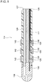
図9は、図8に示した電極カテーテルのカテーテル先端部分114を示す断面図であり、同図において、120はカテーテル先端部分114の管壁に形成された側孔、117はたわみ構造体(断面が矩形の板)、130は導線、126および127はルーメン、129は注入管である。
9 is a cross-sectional view showing the
先端電極138およびリング状電極140は、それぞれ、別個の導線130に接続されている。これらの導線130は金属芯線を樹脂被覆してなる。リング状電極140に接続されている導線130は、それぞれの先端部分において、リング状電極140の内周面にスポット溶接されるとともに、カテーテル先端部分114の管壁に形成された側孔120からルーメン126に進入し、このルーメン126、カテーテル本体110のルーメンおよび制御ハンドル116の内孔に延在し、それぞれの後端部分においてコネクタ118に接続されている。
The
リング状電極140をカテーテル先端部分114に装着する方法としては、カテーテル先端部分114の管壁に形成された側孔120に導線130を通してルーメン126に挿入すると共に、導線130の先端部分の被覆樹脂を剥離して露出させた金属芯線をリング状電極138の内周面にスポット溶接し、次に、このリング状電極138をカテーテル先端部分114の外周に摺動可能に嵌合し、側孔120の開口を塞ぐことのできる位置まで、カテーテル先端部分114の軸方向に沿って摺動(スライド)させ、当該位置においてポリウレタン接着剤などを用いて固定する方法が行われている。
As a method of attaching the ring-
しかしながら、上記の特許文献1で紹介されたものを含めて従来公知の電極カテーテルには、下記のような問題がある。
カテーテルのルーメンに導線を引き通す操作は煩雑であり、この操作中に、導線が破断(断線)してしまうことがある。
また、リング状電極の内周面に対し導線の先端部分を溶接する操作も煩雑であり、また、溶接(スポット溶接)によって十分な接合強度を確保することができない場合があり、リング状電極から導線が外れてしまうことがある。
更に、カテーテルのルーメンには、先端偏向操作のための偏向機構(引張ワイヤおよび板バネ)などが配置されており、導線を引き通すための十分な空間を確保することができない。特に、多数の電極が装着されている電極カテーテルにおいて、これらの電極の各々に接続された多数の導線を狭いルーメンに引き通すことはきわめて困難である。
また、ルーメン内に引き通した導線が引張ワイヤなどで擦られることによって損傷し、当該導線が破断することがある。
However, conventionally known electrode catheters including those introduced in
The operation of passing the lead wire through the lumen of the catheter is complicated, and the lead wire may be broken (disconnected) during this operation.
Also, the operation of welding the tip of the conductor to the inner peripheral surface of the ring-shaped electrode is complicated, and sufficient bonding strength may not be ensured by welding (spot welding). The conductor may be disconnected.
Furthermore, a deflection mechanism (a pulling wire and a leaf spring) for the tip deflection operation is disposed in the lumen of the catheter, and a sufficient space for passing the conducting wire cannot be secured. In particular, in an electrode catheter equipped with a large number of electrodes, it is extremely difficult to pass a large number of conductors connected to each of these electrodes through a narrow lumen.
Moreover, the conducting wire passed through the lumen may be damaged by rubbing with a tensile wire or the like, and the conducting wire may be broken.
本発明は以上のような事情に基いてなされたものである。
本発明の第1の目的は、リング状電極とコネクタの端子とを電気的に接続するための配線操作を容易に行うことができ、生産性に優れた電極カテーテルを提供することにある。 本発明の第2の目的は、リング状電極とコネクタの端子とを電気的に接続する導線の破断を防止することができる電極カテーテルを提供することにある。
本発明の第3の目的は、リング状電極に対する導線の接合強度が高い電極カテーテルを提供することにある。
本発明の第4の目的は、ルーメンにおいて導線を引き通すための空間を必要とせず、ルーメンを有効に利用することができる電極カテーテルを提供することにある。
The present invention has been made based on the above situation.
A first object of the present invention is to provide an electrode catheter that can easily perform a wiring operation for electrically connecting a ring electrode and a terminal of a connector and is excellent in productivity. A second object of the present invention is to provide an electrode catheter that can prevent breakage of a conducting wire that electrically connects a ring-shaped electrode and a terminal of a connector.
A third object of the present invention is to provide an electrode catheter having a high bonding strength of a conducting wire to a ring-shaped electrode.
A fourth object of the present invention is to provide an electrode catheter that does not require a space for passing a lead wire in the lumen and can effectively use the lumen.
(1)本発明の電極カテーテルは、絶縁性のチューブ部材と、
前記チューブ部材の基端側に接続された制御ハンドルと、
前記制御ハンドルに固定され、前記制御ハンドル内において端子を有するコネクタと、 前記チューブ部材の先端領域の外周面に固定されたリング状電極と、
前記チューブ部材の管壁内に配置されたFPC基板とを備えてなり;
前記FPC基板は、前記チューブ部材の管壁内を管軸方向に延びる長尺フィルム部と、 前記チューブ部材の円周方向に延び、前記リング状電極の固定位置において前記チューブ部材に巻き付けられた拡幅フィルム部と、
前記拡幅フィルム部上に形成された金属箔からなり、前記リング状電極の内周面が固着される接点層と、
前記長尺フィルム部上に形成された金属箔からなり、その先端が前記接点層に接続され、前記チューブ部材の管壁内を管軸方向に延びて、その後端が前記コネクタの端子と電気的に接続される導線層と
を有していることを特徴とする。
(1) The electrode catheter of the present invention comprises an insulating tube member;
A control handle connected to the proximal side of the tube member;
A connector fixed to the control handle and having a terminal in the control handle; a ring electrode fixed to an outer peripheral surface of a distal end region of the tube member;
An FPC board disposed in a tube wall of the tube member;
The FPC board includes a long film portion extending in a tube axis direction within a tube wall of the tube member, and a widened portion that extends in a circumferential direction of the tube member and is wound around the tube member at a fixing position of the ring electrode. A film part;
A metal foil formed on the widened film portion, a contact layer to which the inner peripheral surface of the ring electrode is fixed,
It consists of a metal foil formed on the long film part, the tip of which is connected to the contact layer, extends in the tube axis direction of the tube member, and its rear end is electrically connected to the connector terminal. And a conductive wire layer connected to.
(2)本発明の電極カテーテルは、絶縁性のチューブ部材と、
前記チューブ部材の基端側に接続された制御ハンドルと、
前記制御ハンドルに固定され、前記制御ハンドル内において複数の端子を有するコネクタと、
前記チューブ部材の先端領域の外周面に各々が離間して固定された複数のリング状電極と、
前記チューブ部材の管壁内に配置されたFPC基板とを備えてなり;
前記FPC基板は、前記チューブ部材の管壁内を管軸方向に延びる長尺フィルム部と、 前記チューブ部材の円周方向に延び、前記リング状電極の各々の固定位置において前記チューブ部材に巻き付けられた複数の拡幅フィルム部と、
前記拡幅フィルム部の各々の上に形成された金属箔からなり、前記リング状電極の各々の内周面が固着される複数の接点層と、
前記長尺フィルム部上に形成された金属箔からなり、各々の先端が前記接点層の各々に接続され、前記チューブ部材の管壁内を互いに絶縁された状態で管軸方向に延び、各々の後端が前記コネクタの端子の各々と電気的に接続される複数の導線層と
を有していることを特徴とする。
(2) The electrode catheter of the present invention comprises an insulating tube member;
A control handle connected to the proximal side of the tube member;
A connector fixed to the control handle and having a plurality of terminals in the control handle;
A plurality of ring-shaped electrodes each spaced apart and fixed to the outer peripheral surface of the distal end region of the tube member;
An FPC board disposed in a tube wall of the tube member;
The FPC board extends in the tube axis direction in the tube wall of the tube member, and extends in the circumferential direction of the tube member, and is wound around the tube member at each fixed position of the ring-shaped electrode. A plurality of widening film portions,
A metal foil formed on each of the widened film portions, a plurality of contact layers to which the inner peripheral surface of each of the ring electrodes is fixed,
The metal film formed on the long film portion, each tip is connected to each of the contact layers, and extends in the tube axis direction while being insulated from each other in the tube wall of the tube member. The rear end has a plurality of conductor layers electrically connected to each of the terminals of the connector .
上記のような構成の電極カテーテルによれば、カテーテルのルーメンに導線を引き通したり、リング状電極の内周面に導線の先端部分を溶接したりする煩雑な操作を行う必要がないので、リング状電極とコネクタの端子とを電気的に接続するための配線操作を容易に行うことができる。
また、FPC基板の導線層は、長尺フィルム部上に形成された金属箔からなるので破断されにくい。従って、本発明の電極カテーテルの製造時および使用時において、この導線層が破断(断線)することを防止することができる。
また、拡幅フィルム部上に形成された金属箔からなる接点層を介して、リング状電極と導線層とが接続されているので、両者の接合面積を十分に確保することができ、リング状電極に対する導線層の接合強度を高くすることができる。
また、FPC基板を構成する導線層が、チューブ部材の管壁内に延びていて、リング状電極に接続された導線をチューブ部材のルーメンに引き通す必要はないので、チューブ部材のルーメン(空間)を有効に利用することができる。
According to the electrode catheter configured as described above, there is no need to perform a complicated operation of passing the lead wire through the lumen of the catheter or welding the tip of the lead wire to the inner peripheral surface of the ring electrode. Wiring operation for electrically connecting the electrode and the terminal of the connector can be easily performed.
Moreover, since the conducting wire layer of an FPC board consists of metal foil formed on the elongate film part, it is hard to be fractured. Therefore, it is possible to prevent the conducting wire layer from being broken (disconnected) during manufacture and use of the electrode catheter of the present invention.
In addition, since the ring-shaped electrode and the conductive wire layer are connected via the contact layer made of the metal foil formed on the widened film portion, the joint area between the two can be sufficiently secured, and the ring-shaped electrode It is possible to increase the bonding strength of the conductive wire layer to.
In addition, since the conducting wire layer constituting the FPC board extends into the tube wall of the tube member and it is not necessary to pass the conducting wire connected to the ring-shaped electrode through the lumen of the tube member, the lumen (space) of the tube member Can be used effectively.
(3)本発明の電極カテーテルにおいて、前記チューブ部材は、内管部(内層)と外管部(外層)とにより構成され、
前記FPC基板は、前記内管部と前記外管部との間に配置され、
前記外管部の壁材の一部が除去されて露出した前記FPC基板の接点層に、前記リング状電極の内周面が固着されることにより、前記リング状電極が前記チューブ部材の先端領域の外周面に固定されていることが好ましい。
(3) In the electrode catheter of the present invention, the tube member is composed of an inner tube portion (inner layer) and an outer tube portion (outer layer),
The FPC board is disposed between the inner tube portion and the outer tube portion,
The inner surface of the ring-shaped electrode is fixed to the contact layer of the FPC board exposed by removing a part of the wall material of the outer tube portion, so that the ring-shaped electrode becomes the tip region of the tube member. It is preferable to be fixed to the outer peripheral surface.
このような構成によれば、FPC基板の導線層をチューブ部材の管壁内に延在させることができるとともに、FPC基板の接点層に対してリング状電極の内周面を確実に固着させることができる。 According to such a configuration, the conductive wire layer of the FPC board can be extended into the tube wall of the tube member, and the inner peripheral surface of the ring-shaped electrode is securely fixed to the contact layer of the FPC board. Can do.
(4)複数のリング状電極を備えた本発明の電極カテーテルにおいて、前記FPC基板は、前記制御ハンドルの内部において、前記チューブ部材の管壁内から延び出し、前記FPC基板の導線層の各々の後端は、前記コネクタの端子の各々と電気的に接続されていることが好ましい。 (4) In the electrode catheter of the present invention having a plurality of ring-shaped electrodes, the FPC board extends from the inside of the tube wall of the tube member inside the control handle, and each of the conductive layers of the FPC board. The rear end is preferably electrically connected to each terminal of the connector.
このような構成によれば、リング状電極とコネクタの端子とを接続するための配線操作を更に容易に行うことができる。
また、制御ハンドルの内部空間を有効に利用することができる。
According to such a configuration, the wiring operation for connecting the ring electrode and the terminal of the connector can be performed more easily.
In addition, the internal space of the control handle can be used effectively.
(5)この場合において、前記コネクタの端子の各々に接続された金属箔からなる複数の導線層を有するコネクタ側FPC基板を備えてなり、
前記チューブ部材の管壁内から延び出した前記FPC基板と、前記コネクタ側FPC基板とを介して、前記リング状電極の各々と、前記コネクタの端子の各々とが電気的に接続されていることが好ましい。
(5) In this case, comprising a connector-side FPC board having a plurality of conductive layers made of metal foil connected to each of the terminals of the connector,
Each of the ring-shaped electrodes and each of the terminals of the connector are electrically connected via the FPC board extending from the tube wall of the tube member and the connector-side FPC board. Is preferred.
(6)また、前記チューブ部材の管壁内から延び出した前記FPC基板と、前記コネクタ側FPC基板とが、雄雌コネクタを介して連結されていることが好ましい。 (6) Moreover, it is preferable that the said FPC board extended from the inside of the tube wall of the said tube member and the said connector side FPC board are connected through the male-female connector.
上記のような構成によれば、FPC基板の導線層の各々と、コネクタの端子の各々とを接続する煩雑な工程を回避することができる。 According to the above configuration, it is possible to avoid a complicated process of connecting each of the conductive wire layers of the FPC board and each of the terminals of the connector.
(7)複数のリング状電極を備えた本発明の電極カテーテルにおいて、前記FPC基板において先端からn番目(但し、nは2以上の整数である)に位置する前記接点層が、少なくとも、先端から(n−1)番目に位置する前記接点層に接続された前記導線層によって分断されていることが好ましい。 (7) In the electrode catheter of the present invention including a plurality of ring-shaped electrodes, the contact layer located nth from the tip (where n is an integer of 2 or more) in the FPC board is at least from the tip It is preferable that the conductor layer is divided by the conductive layer connected to the (n-1) th contact layer.
このようなパターン構成により、複数のリング状電極相互間の絶縁状態を確保することができる。 With such a pattern configuration, it is possible to ensure insulation between a plurality of ring-shaped electrodes.
本発明の電極カテーテルによれば、リング状電極とコネクタの端子とを接続するための配線操作を容易に行うことができ、その生産性に優れている。
本発明の電極カテーテルによれば、リング状電極とコネクタの端子とを接続する導線(導線層)の破断(断線)を防止することができる。
本発明の電極カテーテルによれば、リング状電極に対する導線(導線層)の接合強度を高くすることができ、リング状電極から導線(導線層)が外れてしまうこと防止することができる。
本発明の電極カテーテルによれば、従来の電極カテーテルのように、ルーメンに導線を引き通す必要がないので、カテーテルチューブのルーメンを有効に利用することができる。
According to the electrode catheter of the present invention, the wiring operation for connecting the ring electrode and the terminal of the connector can be easily performed, and the productivity is excellent.
According to the electrode catheter of the present invention, it is possible to prevent breakage (disconnection) of a conductive wire (conductive wire layer) that connects the ring-shaped electrode and the terminal of the connector.
According to the electrode catheter of the present invention, the bonding strength of the conducting wire (conducting wire layer) to the ring-shaped electrode can be increased, and the conducting wire (conducting wire layer) can be prevented from coming off from the ring-shaped electrode.
According to the electrode catheter of the present invention, unlike the conventional electrode catheter, it is not necessary to pass a lead wire through the lumen, so that the lumen of the catheter tube can be used effectively.
以下、本発明の電極カテーテルについて図面を用いて説明する。
<実施形態>
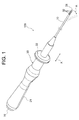
図1〜図4に示す本実施形態の電極カテーテル100は、例えば、心臓における不整脈の診断または治療に用いられるものである。
Hereinafter, the electrode catheter of the present invention will be described with reference to the drawings.
<Embodiment>
The
本実施形態の電極カテーテル100は、内管部10A(内層)および外管部10B(外層)により構成されたカテーテルチューブ10(チューブ部材)と、カテーテルチューブ10の基端側に接続された制御ハンドル20と、制御ハンドル20の基端側に固定され、この制御ハンドル20内において複数の端子を有するコネクタ70と、カテーテルチューブ10の先端に固定された先端電極31と、先端電極31に接続された導線46と、カテーテルチューブ10の先端領域の外周面に各々が離間して固定された4個のリング状電極32と、リング状電極32の各々とコネクタ70の端子の各々とを電気的に接続するために、カテーテルチューブ10の管壁内(内管部10Aと外管部10Bとの間)に配置(埋設)されるとともに、制御ハンドル20の内部において、カテーテルチューブ10の管壁内から延び出しているFPC基板40と、カテーテルチューブ10の先端部分におけるルーメンに延在する板バネ55と、カテーテルチューブ10の中心軸から偏心してルーメンに延在し、その後端が引張可能である引張ワイヤ50と、コネクタ70の端子の各々に接続された金属箔からなる4本の導線層84を有するコネクタ側FPC基板80とを備えてなる。
The
本実施形態の電極カテーテル100を構成するFPC基板40は、カテーテルチューブ10の管壁内を管軸方向に延びる長尺フィルム部41と、カテーテルチューブ10の円周方向に延び、リング状電極32の各々の固定位置においてカテーテルチューブ10(内管部10A)に巻き付けられた4つの拡幅フィルム部42と、拡幅フィルム部42の各々の上に形成された金属箔からなり、リング状電極32の内周面が固着される4つの接点層43と、長尺フィルム部41上に形成された金属箔からなり、各々の先端が接点層43の各々に接続され、カテーテルチューブ10の管壁内を互いに絶縁された状態で管軸方向に延び、各々の後端がコネクタ70の端子の各々と電気的に接続される4本の導線層44とを有し、
FPC基板40(導線層44)と、コネクタ側FPC基板80(導線層84)とを介して、リング状電極32の各々と、コネクタ70の端子の各々とが電気的に接続されている。
The
Each of the ring-shaped
カテーテルチューブ10は、内管部10A(内層)および外管部10B(外層)により構成されたシングルルーメン構造のチューブである。
カテーテルチューブ10(内管部10Aおよび外管部10B)は管軸方向に沿って同じ特性のチューブで構成してもよいが、比較的可撓性に優れた先端部分と、先端部分に対して管軸方向に一体に形成され、先端部分よりも比較的に剛性のある基端部分とを有していることが好ましい。
カテーテルチューブ10(内管部10Aおよび外管部10B)の構成材料としては、例えばポリオレフィン、ポリアミド、ポリエーテルポリアミド、ポリウレタンなどの合成樹脂を挙げることができる。
The
The catheter tube 10 (the
Examples of the constituent material of the catheter tube 10 (the
カテーテルチューブ10(外管部10B)の外径は、通常0.6〜3.0mmとされ、好ましくは1.3〜3.0mmとされる。
カテーテルチューブ10(内管部10A)の内径は、通常0.5〜2.5mmとされ、好ましくは1.0〜1.5mmとされる。
カテーテルチューブ10の長さは、通常400〜1500mmとされ、好ましくは700〜1200mmとされる。
The outer diameter of the catheter tube 10 (
The inner diameter of the catheter tube 10 (
The length of the
カテーテルチューブ10の先端部分は、引張ワイヤ50を引っ張ることによって撓む(曲がる)ことができる。可撓性のある先端部分の長さは、例えば30〜200mmとされる。
The distal end portion of the
カテーテルチューブ10の基端側には制御ハンドル20が接続されている。
図1において、21はグリップ、22はノブである。
制御ハンドル20のノブ22を、図1に示すX方向(先端側または後端側)にスライドさせることにより、引張ワイヤ50の後端が引っ張られ、カテーテルチューブ10の先端部分を図1に示すA方向に撓ませることができる。また、制御ハンドル20を回転させることにより、その回転トルクをカテーテルチューブ10に伝達することができる。
従って、制御ハンドル20を操作することにより、カテーテルチューブ10の先端部分を目的部位に誘導することができる。
A control handle 20 is connected to the proximal end side of the
In FIG. 1, 21 is a grip and 22 is a knob.
By sliding the
Therefore, by operating the control handle 20, the distal end portion of the
制御ハンドル20の基端側の内部には、複数の端子を有するコネクタ70が配置されている。コネクタ70の端子の各々は、先端電極31およびリング状電極32の各々と電気的に接続される。
A
カテーテルチューブ10の先端には先端電極31が固定されている。
先端電極31は、例えばアルミニウム、銅、ステンレス、金、白金など、電気伝導性の良好な金属で構成される。なお、X線に対する造影性を良好に持たせるためには、白金などで構成されることが好ましい。先端電極31の外径は、特に限定されないが、カテーテルチューブ10の外径と同程度であることが好ましい。
先端電極31の外径は特に限定されないが、カテーテルチューブ10の外径と同程度であることが好ましく、通常0.6〜3mm程度である。
先端電極31には導線46が接続されている。先端電極31に接続された導線46は、金属芯線を樹脂被覆してなり、カテーテルチューブ10のルーメン、制御ハンドル20の内孔に延在し、コネクタ70の端子に接続される。
A
The
The outer diameter of the
A
先端電極31の内側凹部には、導線46、板バネ55および引張ワイヤ50を先端電極31に接続固定するためのはんだ60が充填されている。
はんだ60の材質は特に限定されるものではなく、例えばSn−Pbが一般的に用いられるが、Sn−Pb−AgやSn−Pb−Cuが用いられてよく、更にPbフリーのSn−Ag−Cu、Sn−Cu、Sn−Ag、Sn−Ag−Cu−Biなどを用いることができる。
The inner concave portion of the
The material of the
カテーテルチューブ10の先端領域の外周面には、4個のリング状電極32が固定されている。
リング状電極32の構成材料としては、先端電極31の構成材料として例示したものと同一の金属を挙げることができ、白金などが好ましい。
リング状電極32の外径は特に限定されないが、カテーテルチューブ10の外径と同程度であることが好ましく、通常0.6〜3mm程度である。
Four
Examples of the constituent material of the ring-shaped
The outer diameter of the ring-shaped
本実施形態の電極カテーテル100において、リング状電極32の電極幅(カテーテルチューブ10の管軸方向における長さ)は、電極の目的などによっても異なるが、0.3〜4.0mmとされ、好適な一例を示せば1.0mmである。
In the
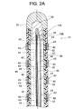
図2A、図2B、図3A、図3Bおよび図3Cに示すように、カテーテルチューブ10の管壁の内部(内管部10Aと外管部10Bとの間)には、FPC(Flexible Pattern Circuit)基板40が配置(埋設)されている。
FPC基板40は、4個のリング状電極32の各々と、コネクタ70の端子の各々とを電気的に接続するための手段であり、FPC基板40がコネクタ側FPC基板80と連結されることにより、リング状電極32の各々とコネクタ70の端子の各々との電気的接続を確保することができる。
As shown in FIG. 2A, FIG. 2B, FIG. 3A, FIG. 3B, and FIG. 3C, the inside of the tube wall of the catheter tube 10 (between the
The
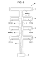
図5に示すように、本実施形態の電極カテーテルを構成するFPC基板40は、絶縁性フィルムである長尺フィルム部41および4つの拡幅フィルム部42と、これらの絶縁性フィルム上にパターン形成された接点層43(431〜434)および4本の導線層44とにより構成されている。同図において、45は、FPC基板40の基端側に取り付けられた中間コネクタ(例えば雄コネクタ)である。
As shown in FIG. 5, the
FPC基板40を構成する長尺フィルム部41は、カテーテルチューブ10の管壁内(内管部10Aと外管部10Bとの間)を管軸方向に延びるよう配置されている。
The
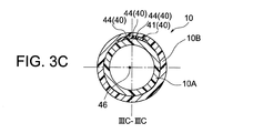
FPC基板40を構成する4つの拡幅フィルム部42は、カテーテルチューブ10の円周方向(長尺フィルム部の延びる方向とは垂直な両方向)に延び、カテーテルチューブ10におけるリング状電極32の各々の固定位置において内管部10Aに巻き付けられている。拡幅フィルム部42の巻き付け角度(図3Aにおけるθ42)としては180〜360°とされ、好ましくは270〜355°とされる。
The four widened
FPC基板40を構成する4つの接点層43は、拡幅フィルム部42(絶縁性フィルム)の各々の上に形成された金属箔(導体箔)からなる。
接点層43の各々には、リング状電極32の内周面が固着されるため、拡幅フィルム部42を内管部10Aに巻き付けるときには、接点層43を、拡幅フィルム部42の外側に位置させる。
カテーテルチューブ10の円周方向における接点層43の形成範囲(図3Aにおけるθ43)としては180〜360°とされ、好ましくは270〜355°とされる。
The four
Since the inner peripheral surface of the ring-shaped
The range of formation of the
FPC基板40を構成する4本の導線層44は、長尺フィルム部41(絶縁性フィルム)上に形成された線状の金属箔(導体箔)からなる。
4本の導線層44は、各々の先端が接点層43の各々に接続され、カテーテルチューブ10の管壁内(内管部10Aと外管部10Bとの間)を互いに絶縁された状態で管軸方向に延びている。
なお、導線層44が形成されている長尺フィルム部41の表面には、図示しない絶縁性薄膜が形成されており、導線層44の各々は、絶縁性材料によって完全に被覆されている。
The four
Each of the four conductive wire layers 44 is connected to each of the contact layers 43, and the tube walls of the catheter tube 10 (between the
In addition, the insulating thin film which is not shown in figure is formed in the surface of the
また、図5に示したように、FPC基板40において、先端から2番目に位置する接点層43(432)は、先端から1番目に位置する接点層43(431)に接続された導線層44により分断され、先端から3番目に位置する接点層43(433)は、先端から1番目および第2番目に位置する接点層43(431,432)に接続された導線層44によって分断され、先端から4番目に位置する接点層43(434)は、先端から1番目乃至第3番目に位置する接点層43(431,432,433)に接続された導線層44によって分断されている。
Further, as shown in FIG. 5, in the
このようなパターン構成によれば、接点層43(431,432,433,434)間の絶縁性、延いては、4個のリング状電極32の相互の絶縁性を確保することができる。なお、接点層43(431,432,433,434)間の絶縁性を確保するためのパターン構成は、図5に示したものに限定されるものではなく、後端側の接点層を避けるように導線層を迂回させるようなパターン構成によっても絶縁性を確保することができる。
According to such a pattern configuration, it is possible to ensure insulation between the contact layers 43 (431, 432, 433, 434), and in turn, insulation between the four
電極カテーテル100を構成するカテーテルチューブ10は、リング状電極32の各々が固定される部分(内管部10Aの外周に拡幅フィルム部42を巻き付けて接点層43を配置した部分)において、接点層43を被覆する外管部10Bの壁材が除去されている(形成されていない)。
これにより、露出する接点層43に対してリング状電極32の内周面を確実に固着させることができ、カテーテルチューブ10の先端領域の外周面にリング状電極32を確実に固定することができる。
The
Thereby, the inner peripheral surface of the ring-shaped
カテーテルチューブ10の外周面にリング状電極32を固定する方法としては、例えば図6に示すように、(1)カテーテルチューブ10を構成する内管部10Aを準備し、(2)内管部10Aの外周の所定の位置(リング状電極32の固定位置)に拡幅フィルム部42の各々を巻き付けて、内管部10Aの外周にFPC基板40を配置し、(3)FPC基板40を配置した内管部10Aの外周を外管部10Bで被覆し、(4)FPC基板40の接点層43の各々を被覆している部分の外管部10Bの壁材をレーザなどにより剥離することにより接点層43を露出させ、(5)リング状電極32を、カテーテルチューブ10(内管部10Aおよび外管部10B)に挿入して接点層43の位置までスライドさせ、接点層43と、リング状電極32(内周面)とを固着させる方法を挙げることができる。 接点層43と、リング状電極32(内周面)との固着方法としては、特に限定されるものではないが、はんだによる固着が好適である。この場合において、接点層43の表面にはんだ層を形成し、リング状電極32の外周面から加熱することにより、十分に固着することができる。
As a method for fixing the ring-shaped
また、カテーテルチューブ10の外周面にリング状電極32を固定する他の方法として、図7に示すように、(1)カテーテルチューブ10を構成する内管部10Aを準備し、(2)接点層43の各々にリング状電極32(内周面)を予め固着させたFPC基板40を、内管部10Aの外周に配置し、(3)リング状電極32が固着されたFPC基板40を配置した内管部10Aの外周を外管部10Bで被覆した後、(4)リング状電極32の各々を被覆している部分の外管部10Bの壁材をレーザなどで剥離することにより、リング状電極32を露出させる方法を採用することもできる。
As another method for fixing the
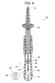
図4に示すように、カテーテルチューブ10の基端部は、制御ハンドル20の内部に挿入され、これにより、カテーテルチューブ10と制御ハンドル20とが接続されている。そして、カテーテルチューブ10の管壁内に埋設されていたFPC基板40は、カテーテルチューブ10が挿入されている制御ハンドル20の内部において、カテーテルチューブ10の管壁内から基端側に延び出して、制御ハンドル20の内部に延在している。
一方、制御ハンドル20の内部に配置されたコネクタ70にも、FPC基板(コネクタ側FPC基板80)が接続されている。
コネクタ側FPC基板80は、コネクタ70の端子の各々に、各々の基端側が接続された4本の導線層(金属箔)84が絶縁性フィルム上に形成されてなる。
また、コネクタ側FPC基板80の先端側には、中間コネクタ85(例えば雌コネクタ)が取り付けられている。
As shown in FIG. 4, the proximal end portion of the
On the other hand, the FPC board (connector side FPC board 80) is also connected to the
The connector-
Further, an intermediate connector 85 (for example, a female connector) is attached to the distal end side of the connector
そして、カテーテルチューブ10の管壁内から基端側に延び出したFPC基板40(導線層44の各々)に取り付けられた中間コネクタ45と、コネクタ側FPC基板80(導線層84の各々)に取り付けられた中間コネクタ85とが結合することにより、リング状電極32の各々と、コネクタ70の端子の各々との電気的な接続が確保される。
And it attaches to the
図2Aに示したように、本実施形態の電極カテーテル100は、カテーテルチューブ10の先端領域を撓ませるための偏向機構として、板バネ55および引張ワイヤ50を備えている。
偏向機構を構成する板バネ55は、撓み方向に変形可能な首振り部材である。
板バネ55は、カテーテルチューブ10の中心軸に沿って、カテーテルチューブ10の先端部分におけるルーメンに延在し、その先端は、内側凹部に充填したはんだ60によって先端電極31に固定されている。
板バネ55の軸方向長さは、特に限定されず、例えば40〜300mmである。板バネ55の幅は、カテーテルチューブ10の内部に収まる程度であれば特に限定されるものではない。
板バネ55の材質も特に限定されず、例えばステンレス、Ni−Ti合金、Co−Ni合金などの金属材料、フッ素樹脂、ポリアミド樹脂などの高分子材料などを挙げることができる。
As shown in FIG. 2A, the
The
The
The axial length of the
The material of the
また、偏向機構を構成する引張ワイヤ50は、カテーテルチューブ10の中心軸から偏心し、かつ、カテーテルチューブ10のルーメンにおいて管軸方向に移動自在に延在している。引張ワイヤ50の先端は、内側凹部に充填されたはんだ60によって先端電極31に固定されている。なお、引張ワイヤ50の先端は板バネ55の先端部に固定されていてもよい。
引張ワイヤ50の後端は、制御ハンドル20の内部に固定され、引張可能となっている。
引張ワイヤ50は、例えばステンレスやNi−Ti系超弾性合金製などの金属で構成することができるが、必ずしも金属で構成する必要はなく、例えば、高強度の非導電性ワイヤなどで構成してもよい。引張ワイヤを非導電性ワイヤで構成することにより、高周波ノイズの原因を低減することができる。
Further, the pulling
The rear end of the
The
オペレータが制御ハンドル20のノブ22をX方向(先端側または後端側)にスライドさせると、制御ハンドル20内の図示しないピストン機構によって、カテーテルチューブ10に対して引張ワイヤ50の後端が引っ張られる。これにより、カテーテルチューブ10の先端部分を撓ませることができる。
なお、偏向機構は、このようなものに限定されるものではないことは勿論である。
When the operator slides the
Of course, the deflection mechanism is not limited to this.
本実施形態の電極カテーテル100によれば、カテーテルチューブ10の管壁内に配置され、制御ハンドル20の内部において、カテーテルチューブ10の管壁内から基端側に延び出しているFPC基板40(接点層43および導線層44)と、コネクタ側FPC基板80(導線層84)とを介して、リング状電極32の各々と、コネクタ70の端子の各々とが電気的に接続されているので、電極カテーテル100を製造する際に、カテーテルチューブのルーメンに導線を引き通したり、リング状電極の内周面に導線の先端部を溶接したりする煩雑な操作を行う必要がなく、リング状電極32の各々とコネクタ70の端子の各々とを接続するための配線操作を容易に行うことができ、生産性に優れている。
According to the
また、FPC基板40を構成する導線層44は、長尺フィルム部41(絶縁性フィルム)上に形成された金属箔からなるので、従来の電極カテーテルで使用していた導線と比較して破断強度が格段に高く、かつ、長尺フィルム部41とともにカテーテルチューブ10の管壁内に埋設されているので、本実施形態の電極カテーテル100の製造時および使用時において、導線層44が破断(断線)することはない。
さらに、導線を使用していた従来の電極カテーテルでは、導線同士の絡みや擦れによる磨耗、各導線のキンクなどの問題があったが、絶縁性フィルム上に導線がプリントされてなるFPC基板40を使用する本実施形態の電極カテーテル100によれば、そのような問題が起こる虞はない。
Moreover, since the
Furthermore, the conventional electrode catheters that have used conductive wires have problems such as tangling or rubbing between the conductive wires, and kinks of the respective conductive wires. However, the
また、拡幅フィルム部42上に形成された金属箔からなる接点層43を介して、リング状電極32と導線層44とが接合されているので、両者の接合面積を十分に確保することができ、リング状電極32に対する導線(導線層44)の接合強度を高くすることができる。この結果、リング状電極32から導線(導線層44)が外れてしまうようなことはない。
Moreover, since the ring-shaped
また、FPC基板40の導線層44が、カテーテルチューブ10の管壁内に延びていて、カテーテルチューブ10のルーメンに引き通される導線は、先端電極31に接続された導線46のみであるので、カテーテルチューブ10のルーメン(空間)を有効に利用することができる。
Moreover, since the
また、制御ハンドル20の内部において、カテーテルチューブ10の管壁内から延び出したFPC基板40と、コネクタ側FPC基板80とが配置され、FPC基板40(導線層44の各々の基端)と、コネクタ側FPC基板80(導線層84の各々の先端)とが、中間コネクタ45および中間コネクタ85とを介して結合されていることにより、FPC基板40の導線層44の各々と、コネクタ70の端子の各々とを導線などで接続する工程を回避することができ、配線操作の更なる容易化を図ることができ、また、制御ハンドル20の内部空間を有効に利用することができる。
Further, an
以上、本発明の一実施形態について説明したが、本発明の電極カテーテルは、これらに限定されるものでなく、種々の偏向が可能である。
例えば、リング状電極の数としては、4個に限定されるものではないことは勿論であり、カテーテルの種類に応じて適宜設定することができる。ここに、リング状電極の数としては、例えば1〜20とされ、好ましくは4〜19とされる。
なお、リング状電極の数が多くなる場合には、FPC基板を複数使用することも可能である。
As mentioned above, although one Embodiment of this invention was described, the electrode catheter of this invention is not limited to these, A various deflection | deviation is possible.
For example, the number of ring electrodes is not limited to four, and can be set as appropriate according to the type of catheter. Here, the number of ring-shaped electrodes is, for example, 1 to 20, preferably 4 to 19.
In addition, when the number of ring-shaped electrodes increases, it is also possible to use a plurality of FPC boards.
10 カテーテルチューブ
10A 内管部
10B 外管部
20 制御ハンドル
21 グリップ
22 ノブ
31 先端電極
32 リング状電極
40 FPC基板
41 長尺フィルム部
42 拡幅フィルム部
43 接点層
44 導線層
45 中間コネクタ
46 導線
50 引張ワイヤ
55 板バネ
60 はんだ
70 コネクタ
80 コネクタ側FPC基板 84 導線層
85 中間コネクタ
DESCRIPTION OF
Claims (7)
前記チューブ部材の基端側に接続された制御ハンドルと、
前記制御ハンドルに固定され、前記制御ハンドル内において端子を有するコネクタと、 前記チューブ部材の先端領域の外周面に固定されたリング状電極と、
前記チューブ部材の管壁内に配置されたFPC基板とを備えてなり;
前記FPC基板は、前記チューブ部材の管壁内を管軸方向に延びる長尺フィルム部と、 前記チューブ部材の円周方向に延び、前記リング状電極の固定位置において前記チューブ部材に巻き付けられた拡幅フィルム部と、
前記拡幅フィルム部上に形成された金属箔からなり、前記リング状電極の内周面が固着される接点層と、
前記長尺フィルム部上に形成された金属箔からなり、その先端が前記接点層に接続され、前記チューブ部材の管壁内を管軸方向に延びて、その後端が前記コネクタの端子と電気的に接続される導線層と
を有していることを特徴とする電極カテーテル。 An insulating tube member;
A control handle connected to the proximal side of the tube member;
A connector fixed to the control handle and having a terminal in the control handle; a ring electrode fixed to an outer peripheral surface of a distal end region of the tube member;
An FPC board disposed in a tube wall of the tube member;
The FPC board includes a long film portion extending in a tube axis direction within a tube wall of the tube member, and a widened portion that extends in a circumferential direction of the tube member and is wound around the tube member at a fixing position of the ring electrode. A film part;
A metal foil formed on the widened film portion, a contact layer to which the inner peripheral surface of the ring electrode is fixed,
It consists of a metal foil formed on the long film part, the tip of which is connected to the contact layer, extends in the tube axis direction of the tube member, and its rear end is electrically connected to the connector terminal. An electrode catheter comprising: a conductive wire layer connected to the electrode catheter.
前記チューブ部材の基端側に接続された制御ハンドルと、
前記制御ハンドルに固定され、前記制御ハンドル内において複数の端子を有するコネクタと、
前記チューブ部材の先端領域の外周面に各々が離間して固定された複数のリング状電極と、
前記チューブ部材の管壁内に配置されたFPC基板とを備えてなり;
前記FPC基板は、前記チューブ部材の管壁内を管軸方向に延びる長尺フィルム部と、 前記チューブ部材の円周方向に延び、前記リング状電極の各々の固定位置において前記チューブ部材に巻き付けられた複数の拡幅フィルム部と、
前記拡幅フィルム部の各々の上に形成された金属箔からなり、前記リング状電極の各々の内周面が固着される複数の接点層と、
前記長尺フィルム部上に形成された金属箔からなり、各々の先端が前記接点層の各々に接続され、前記チューブ部材の管壁内を互いに絶縁された状態で管軸方向に延び、各々の後端が前記コネクタの端子の各々と電気的に接続される複数の導線層と
を有していることを特徴とする電極カテーテル。 An insulating tube member;
A control handle connected to the proximal side of the tube member;
A connector fixed to the control handle and having a plurality of terminals in the control handle;
A plurality of ring-shaped electrodes each spaced apart and fixed to the outer peripheral surface of the distal end region of the tube member;
An FPC board disposed in a tube wall of the tube member;
The FPC board extends in the tube axis direction in the tube wall of the tube member, and extends in the circumferential direction of the tube member, and is wound around the tube member at each fixed position of the ring-shaped electrode. A plurality of widening film portions,
A metal foil formed on each of the widened film portions, a plurality of contact layers to which the inner peripheral surface of each of the ring electrodes is fixed,
The metal film formed on the long film portion, each tip is connected to each of the contact layers, and extends in the tube axis direction while being insulated from each other in the tube wall of the tube member. An electrode catheter comprising: a plurality of conductor layers whose rear ends are electrically connected to each of the terminals of the connector.
前記FPC基板は、前記内管部と前記外管部との間に配置され、
前記外管部の壁材の一部が除去されて露出した前記FPC基板の接点層に、前記リング状電極の内周面が固着されることにより、前記リング状電極が前記チューブ部材の先端領域の外周面に固定されていることを特徴とする請求項1または請求項2に記載の電極カテーテル。 The tube member is composed of an inner tube portion and an outer tube portion,
The FPC board is disposed between the inner tube portion and the outer tube portion,
The inner surface of the ring-shaped electrode is fixed to the contact layer of the FPC board exposed by removing a part of the wall material of the outer tube portion, so that the ring-shaped electrode becomes the tip region of the tube member. The electrode catheter according to claim 1 or 2, wherein the electrode catheter is fixed to an outer peripheral surface of the electrode catheter.
前記チューブ部材の管壁内から延び出した前記FPC基板と、前記コネクタ側FPC基板とを介して、前記リング状電極の各々と、前記コネクタの端子の各々とが電気的に接続されていることを特徴とする請求項4に記載の電極カテーテル。 Comprising a connector-side FPC board having a plurality of conductive layers made of metal foil connected to each of the terminals of the connector;
Each of the ring-shaped electrodes and each of the terminals of the connector are electrically connected via the FPC board extending from the tube wall of the tube member and the connector-side FPC board. The electrode catheter according to claim 4.
Priority Applications (2)
| Application Number | Priority Date | Filing Date | Title |
|---|---|---|---|
| JP2011057079A JP5253535B2 (en) | 2011-03-15 | 2011-03-15 | Electrode catheter |
| PCT/JP2012/051982 WO2012124391A1 (en) | 2011-03-15 | 2012-01-30 | Electrode catheter |
Applications Claiming Priority (1)
| Application Number | Priority Date | Filing Date | Title |
|---|---|---|---|
| JP2011057079A JP5253535B2 (en) | 2011-03-15 | 2011-03-15 | Electrode catheter |
Publications (3)
| Publication Number | Publication Date |
|---|---|
| JP2012192005A JP2012192005A (en) | 2012-10-11 |
| JP2012192005A5 JP2012192005A5 (en) | 2013-05-16 |
| JP5253535B2 true JP5253535B2 (en) | 2013-07-31 |
Family
ID=46830472
Family Applications (1)
| Application Number | Title | Priority Date | Filing Date |
|---|---|---|---|
| JP2011057079A Expired - Fee Related JP5253535B2 (en) | 2011-03-15 | 2011-03-15 | Electrode catheter |
Country Status (2)
| Country | Link |
|---|---|
| JP (1) | JP5253535B2 (en) |
| WO (1) | WO2012124391A1 (en) |
Cited By (3)
| Publication number | Priority date | Publication date | Assignee | Title |
|---|---|---|---|---|
| WO2016048001A1 (en) * | 2014-09-23 | 2016-03-31 | 주식회사 한독 | Catheter and manufacturing method therefor |
| EP3950034A4 (en) * | 2019-03-29 | 2022-12-14 | Toray Industries, Inc. | Method for manufacturing catheter and catheter manufactured by said method |
| US11931099B2 (en) | 2018-02-05 | 2024-03-19 | Nippon Mektron, Ltd. | Catheter flexible printed wiring board and method for manufacturing the same |
Families Citing this family (5)
| Publication number | Priority date | Publication date | Assignee | Title |
|---|---|---|---|---|
| KR102033759B1 (en) * | 2014-09-23 | 2019-10-17 | 주식회사 한독칼로스메디칼 | Catheter and manufacturing method thereof |
| KR102033760B1 (en) * | 2014-09-23 | 2019-10-17 | 주식회사 한독칼로스메디칼 | Catheter and manufacturing method thereof |
| US10912475B2 (en) * | 2016-08-24 | 2021-02-09 | Biosense Webster (Israel) Ltd | Catheter with split electrode sleeve and related methods |
| WO2019232256A1 (en) * | 2018-05-31 | 2019-12-05 | St. Jude Medical, Cardiology Division, Inc. | Catheter handle with compliant circuit |
| US20210059746A1 (en) * | 2019-08-30 | 2021-03-04 | Biosense Webster (Israel) Ltd. | Ent guidewire |
Family Cites Families (4)
| Publication number | Priority date | Publication date | Assignee | Title |
|---|---|---|---|---|
| US5156151A (en) * | 1991-02-15 | 1992-10-20 | Cardiac Pathways Corporation | Endocardial mapping and ablation system and catheter probe |
| JPH09135820A (en) * | 1995-11-13 | 1997-05-27 | Riken Densen Kk | Structure for connecting terminal of signal line from multi-polar probe |
| JP2006325985A (en) * | 2005-05-26 | 2006-12-07 | Inter Noba Kk | Inspection catheter and medical inspection instrument |
| WO2007139479A1 (en) * | 2006-06-01 | 2007-12-06 | Cathprint Ab | Tubular catheter for invasive use and manufacturing method therefor |
-
2011
- 2011-03-15 JP JP2011057079A patent/JP5253535B2/en not_active Expired - Fee Related
-
2012
- 2012-01-30 WO PCT/JP2012/051982 patent/WO2012124391A1/en active Application Filing
Cited By (3)
| Publication number | Priority date | Publication date | Assignee | Title |
|---|---|---|---|---|
| WO2016048001A1 (en) * | 2014-09-23 | 2016-03-31 | 주식회사 한독 | Catheter and manufacturing method therefor |
| US11931099B2 (en) | 2018-02-05 | 2024-03-19 | Nippon Mektron, Ltd. | Catheter flexible printed wiring board and method for manufacturing the same |
| EP3950034A4 (en) * | 2019-03-29 | 2022-12-14 | Toray Industries, Inc. | Method for manufacturing catheter and catheter manufactured by said method |
Also Published As
| Publication number | Publication date |
|---|---|
| JP2012192005A (en) | 2012-10-11 |
| WO2012124391A1 (en) | 2012-09-20 |
Similar Documents
| Publication | Publication Date | Title |
|---|---|---|
| JP5253535B2 (en) | Electrode catheter | |
| JP4940332B2 (en) | catheter | |
| EP2079513B1 (en) | A medical implantable lead including a flexible flat twisted elongate body | |
| US9326729B2 (en) | Electrode catheter and method for manufacturing the same | |
| JP4526585B2 (en) | Tip deflectable catheter | |
| WO2013088840A1 (en) | Catheter having distal end capable of being deflected by operation | |
| CN111683716B (en) | Catheter and method of manufacturing the same | |
| WO2011121931A2 (en) | Catheter | |
| JP2017148472A (en) | Electrode catheter | |
| JP5875175B2 (en) | Electrode catheter | |
| JP5557393B2 (en) | Tip deflectable catheter | |
| JP5174542B2 (en) | catheter | |
| JP4544457B2 (en) | Tip deflectable catheter | |
| JP6529770B2 (en) | Electrode catheter, manufacturing method of electrode catheter | |
| WO2014196249A1 (en) | Catheter having bendable tip | |
| WO2021070543A1 (en) | Catheter and method for manufacturing same | |
| WO2020194474A1 (en) | Catheter | |
| JP7187331B2 (en) | Catheter manufacturing method | |
| JP7464600B2 (en) | Catheter and method for manufacturing same | |
| CN109804505B (en) | Catheter tube | |
| JP2023068574A (en) | electrode catheter | |
| WO2020071084A1 (en) | Electrode catheter | |
| JP2024049769A (en) | Method for manufacturing electrode catheter and catheter shaft | |
| JP2023030906A (en) | electrode catheter | |
| JP5618779B2 (en) | Ablation catheter |
Legal Events
| Date | Code | Title | Description |
|---|---|---|---|
| A521 | Request for written amendment filed |
Free format text: JAPANESE INTERMEDIATE CODE: A523 Effective date: 20130327 |
|
| A621 | Written request for application examination |
Free format text: JAPANESE INTERMEDIATE CODE: A621 Effective date: 20130327 |
|
| A871 | Explanation of circumstances concerning accelerated examination |
Free format text: JAPANESE INTERMEDIATE CODE: A871 Effective date: 20130327 |
|
| TRDD | Decision of grant or rejection written | ||
| A975 | Report on accelerated examination |
Free format text: JAPANESE INTERMEDIATE CODE: A971005 Effective date: 20130410 |
|
| A01 | Written decision to grant a patent or to grant a registration (utility model) |
Free format text: JAPANESE INTERMEDIATE CODE: A01 Effective date: 20130415 |
|
| A61 | First payment of annual fees (during grant procedure) |
Free format text: JAPANESE INTERMEDIATE CODE: A61 Effective date: 20130416 |
|
| R150 | Certificate of patent or registration of utility model |
Ref document number: 5253535 Country of ref document: JP Free format text: JAPANESE INTERMEDIATE CODE: R150 Free format text: JAPANESE INTERMEDIATE CODE: R150 |
|
| FPAY | Renewal fee payment (event date is renewal date of database) |
Free format text: PAYMENT UNTIL: 20160426 Year of fee payment: 3 |
|
| R250 | Receipt of annual fees |
Free format text: JAPANESE INTERMEDIATE CODE: R250 |
|
| R250 | Receipt of annual fees |
Free format text: JAPANESE INTERMEDIATE CODE: R250 |
|
| R250 | Receipt of annual fees |
Free format text: JAPANESE INTERMEDIATE CODE: R250 |
|
| R250 | Receipt of annual fees |
Free format text: JAPANESE INTERMEDIATE CODE: R250 |
|
| LAPS | Cancellation because of no payment of annual fees |