JP5247098B2 - Image forming apparatus and control method thereof - Google Patents
Image forming apparatus and control method thereof Download PDFInfo
- Publication number
- JP5247098B2 JP5247098B2 JP2007244445A JP2007244445A JP5247098B2 JP 5247098 B2 JP5247098 B2 JP 5247098B2 JP 2007244445 A JP2007244445 A JP 2007244445A JP 2007244445 A JP2007244445 A JP 2007244445A JP 5247098 B2 JP5247098 B2 JP 5247098B2
- Authority
- JP
- Japan
- Prior art keywords
- activation
- unit
- control means
- state
- return
- Prior art date
- Legal status (The legal status is an assumption and is not a legal conclusion. Google has not performed a legal analysis and makes no representation as to the accuracy of the status listed.)
- Active
Links
Images


Description
本発明は、省エネルギー状態からの復帰処理を最適化したプリンタや複写機などの画像形成装置に関するものである。 The present invention relates to an image forming apparatus such as a printer or a copying machine that optimizes a return process from an energy saving state.
近年の画像形成装置は、環境問題やエネルギー問題における対策として、待機時には省エネルギー状態又は省エネルギーモードと呼ばれる状態を有し消費電力を低減する機能を備える。省エネルギーモードにおいては、画像形成装置は、スタンバイ状態とは異なり、定着装置の保温を停止するなど消費電力を低減する状態となる。また、近年は画像形成装置に接続される外部機器、オプション装置などの通電も遮断して消費電力を低減するシステムも多くなっている。さらに電力を削減するために、制御CPUをオフにするシステムも提案されている。 Recent image forming apparatuses have a function of reducing power consumption in a state called an energy saving state or an energy saving mode during standby as a countermeasure against environmental problems and energy problems. In the energy saving mode, unlike the standby state, the image forming apparatus is in a state of reducing power consumption, such as stopping the heat retention of the fixing device. In recent years, there are an increasing number of systems that cut off the power supply to external devices and optional devices connected to the image forming apparatus to reduce power consumption. In order to further reduce power, a system for turning off the control CPU has also been proposed.
画像形成装置においては、ホストコンピュータと接続され印刷を受け付けるコントローラ部と、画像形成部を制御するエンジン部が存在し、近年はコントローラ部のみを通電して、エンジン部の通電を止めることにより、さらなる省エネルギー化を実現している。このように、エンジン部の通電を停止させた場合、エンジン部の制御CPUは、何れもオフからオンへの状態変化であるため、画像形成装置の電源オンであるのか、又は省エネルギーモードからの復帰によるオンであるのかの区別が付かない。したがって、省エネルギー時にもオフにならないコントローラ部からの指示を受けない限り、エンジン部の制御CPUは適切な起動制御が行えないという問題があった。 In an image forming apparatus, there is a controller unit that is connected to a host computer and receives printing, and an engine unit that controls the image forming unit. In recent years, by energizing only the controller unit and stopping energization of the engine unit, Energy saving is realized. In this way, when the energization of the engine unit is stopped, the control CPU of the engine unit is in a state change from off to on, so that the image forming apparatus is powered on or returned from the energy saving mode. I cannot distinguish whether it is on. Therefore, there has been a problem that the control CPU of the engine unit cannot perform appropriate start-up control unless it receives an instruction from the controller unit that does not turn off during energy saving.
特許文献1には、完全省エネルギー状態からの復帰時の装置立ち上げ動作を、電源オン時の装置立ち上げ動作と異ならせる省エネルギー復帰方法が提案されている。具体的に、省エネルギー用CPUで、省エネルギー状態からの復帰要因の発生を検出すると、復帰要因の検出結果を自ポートに保持した後に、本体用CPUを起動させている。起動された本体用CPUは、省エネルギー用CPUのポートを読み、復帰要因の検出結果の有無を判別する。復帰要因の検出結果の有無に応じて異なる初期化手順により、ファクシミリ装置の初期化を行う。例えば、復帰要因を検出していなければ、本体用CPUは、ファクシミリ装置の電源スイッチがオンされた場合の初期化手順、即ち、感光体のクリーニングを含む初期化動作を行う。また、復帰要因が検出されていれば、復帰要因に対応して予め定められた初期化手順により装置の初期化を行うことが提案されている。
しかしながら、従来のエンジン部の通電を停止させた省エネルギーモードにおいて、エンジン部の制御CPUは、オフからオンへの状態変化であるため、画像形成装置の電源投入であるのか、省エネルギーモードからの復帰であるのかの区別が付かない。したがって、省エネルギー時にもオフにならないコントローラ部からの指示を受けない限り、エンジン部の制御CPUは適切な起動制御が行えない。そのため、エンジン部の制御CPUには、コントーラ部のCPUから起動状態を通知してもらう仕組みを設けることが望ましい。しかし、この仕組みを用いた場合、エンジン部の制御CPUは、コントローラ部の起動状態通知を待つ必要がある。コントローラ部のCPUも省エネルギー状態のときは節電モードとなっているため、コントローラ部も本来の起動状態になるには時間がかかり、エンジン部の制御CPUに起動状態通知を行うには時間がかかってしまう。よって、画像形成装置としては、起動時間、又は省エネルギーモードからの復帰時間が長くかかってしまうという問題がある。 However, in the conventional energy-saving mode in which the energization of the engine unit is stopped, the control CPU of the engine unit is in a state change from off to on, so whether the image forming apparatus is powered on or returned from the energy-saving mode. I can't tell if it is. Therefore, the control CPU of the engine unit cannot perform appropriate start-up control unless it receives an instruction from the controller unit that does not turn off even during energy saving. For this reason, it is desirable that the control CPU of the engine unit be provided with a mechanism for notifying the activation state from the CPU of the controller unit. However, when this mechanism is used, the control CPU of the engine unit needs to wait for the activation state notification of the controller unit. Since the CPU of the controller unit is in the power saving mode when the energy saving state is also in effect, it takes time for the controller unit to enter the original activation state, and it takes time to notify the control CPU of the engine unit of the activation state. Therefore, the image forming apparatus has a problem that it takes a long time to start up or return from the energy saving mode.
本発明は、上述の問題に鑑みて成されたものであり、起動状態に関わらず、コントローラ部の起動とともにエンジン部の起動を実行することで起動時間を高速化する画像形成装置を提供することを目的とする。 The present invention has been made in view of the above-described problems, and provides an image forming apparatus that speeds up the startup time by executing the startup of the engine unit together with the startup of the controller unit regardless of the startup state. With the goal.
本発明は、例えば、装置を統括的に制御する第1制御手段と、該第1制御手段からの指示に従って記録材に画像を形成する画像形成処理を制御する第2制御手段とを備え、該第1制御手段及び該第2制御手段の動作状態として、該第1制御手段の一部の機能及び該第2制御手段の全ての機能を停止することで消費電力を制限する省エネルギー状態と、該第1制御手段及び該第2制御手段の全ての機能を停止する停止状態とを有する画像形成装置であって、前記停止状態にある前記第2制御手段を起動させるための起動処理を実行する起動手段と、前記省エネルギー状態にある前記第2制御手段を起動させる復帰処理であって、前記起動処理の一部となる前記復帰処理を実行する復帰手段と、前記停止状態又は前記省エネルギー状態の何れの状態から起動されたかに関わらず、前記第1制御手段の起動時の処理と同時に前記復帰手段による復帰処理を実行させ、前記第1制御手段が起動した後に前記第2制御手段に対して通知される起動前の動作状態を示す起動情報が前記停止状態を示す場合に前記起動手段による起動処理を実行させる起動調整手段と、を備えており、前記起動調整手段は、前記復帰処理を実行させた後に、前記第1制御手段から通知される前記起動情報を受信するまで前記起動手段による起動処理を待機させる待機手段を備えており、前記起動処理を実行させる場合には、該起動処理のうち、既に実行されている復帰処理と重複しない処理のみを実行させることを特徴とする。
The present invention includes, for example, first control means for comprehensively controlling the apparatus, and second control means for controlling image forming processing for forming an image on a recording material in accordance with an instruction from the first control means, As an operation state of the first control means and the second control means, an energy saving state that limits power consumption by stopping a part of the functions of the first control means and all the functions of the second control means, and An image forming apparatus having a stopped state in which all the functions of the first control unit and the second control unit are stopped, wherein the startup is performed to start the second control unit in the stopped state A return process for starting the second control means in the energy saving state, a return means for executing the return process that is a part of the startup process, and either the stop state or the energy saving state Condition Regardless of whether the first control means is activated or not, the restoration process by the restoration means is executed simultaneously with the process at the time of activation of the first control means, and the second control means is notified after the first control means is activated. A start adjustment unit that executes a start process by the start unit when start information indicating an operation state before start indicates the stop state, and the start adjustment unit performs the return process A standby unit that waits for the startup process by the startup unit until the startup information notified from the first control unit is received, and when the startup process is executed, Only the processing that does not overlap with the return processing being executed is executed .
また、本発明は、例えば、装置を統括的に制御する第1制御手段と、該第1制御手段からの指示に従って記録材に画像を形成する画像形成処理を制御する第2制御手段とを備え、該第1制御手段及び該第2制御手段の動作状態として、該第1制御手段の一部の機能及び該第2制御手段の全ての機能を停止することで消費電力を制限する省エネルギー状態と、該第1制御手段及び該第2制御手段の全ての機能を停止する停止状態とを有する画像形成装置の制御方法であって、前記停止状態にある前記第2制御手段を起動させるための起動処理と、前記省エネルギー状態にある前記第2制御手段を起動させる復帰処理であって、前記起動処理の一部となる前記復帰処理と、を有し、前記停止状態又は前記省エネルギー状態の何れの状態から起動されたかに関わらず、前記第1制御手段の起動時の処理と同時に前記復帰処理を実行するステップと、前記第1制御手段が起動した後に前記第2制御手段に対して通知される起動前の動作状態を示す起動情報が前記停止状態を示す場合に前記起動処理を実行するステップと、を含み、前記復帰処理を実行した後に、前記第1制御手段から通知される前記起動情報を受信するまで前記起動処理を待機させ、前記起動処理を実行する場合には、該起動処理のうち、既に実行した復帰処理と重複しない処理のみを実行することを特徴とする。 The present invention also includes, for example, first control means for comprehensively controlling the apparatus, and second control means for controlling image forming processing for forming an image on a recording material in accordance with an instruction from the first control means. As the operating states of the first control means and the second control means, an energy saving state in which power consumption is limited by stopping a part of the functions of the first control means and all the functions of the second control means; A control method for an image forming apparatus having a stopped state in which all the functions of the first control unit and the second control unit are stopped, the start-up for starting up the second control unit in the stopped state and processing, a return process for activating the second control means in said energy saving state, anda the return process become part of the activation process, one of the state of the stop state or the energy-saving state Launched from Regardless of Taka, and executing simultaneously the return processing and the processing of the startup of the first control means, activated prior to operation of said first control means is notified to the second control means after starting comprises the steps that perform the activation process if the start information indicating a state indicating the stop state, after performing the return processing, until receiving the activation information notified from said first control means When the activation process is made to wait and the activation process is executed, only the process that does not overlap with the already-executed return process is executed .
本発明は、例えば、起動状態に関わらず、コントローラ部の起動とともにエンジン部の起動を実行することで起動時間を高速化する画像形成装置を提供できる。 The present invention can provide, for example, an image forming apparatus that speeds up the startup time by executing the startup of the engine unit together with the startup of the controller unit regardless of the startup state.
以下に本発明の一実施形態を示す。以下で説明される個別の実施形態は、本発明の上位概念、中位概念及び下位概念など種々の概念を理解するために役立つであろう。また、本発明の技術的範囲は、特許請求の範囲によって確定されるのであって、以下の個別の実施形態によって限定されるわけではない。 An embodiment of the present invention is shown below. The individual embodiments described below will help to understand various concepts, such as superordinate concepts, intermediate concepts and subordinate concepts of the present invention. Further, the technical scope of the present invention is determined by the scope of the claims, and is not limited by the following individual embodiments.
[第1の実施形態]
以下では、図1乃至図6を参照して、第1の実施形態について説明する。図1は、第1の実施形態に係るプリンタ101を示す断面図である。本実施形態では、画像形成装置の一適用例として、レーザビームプリンタであるプリンタ101を用いて説明する。しかし、本発明は、画像形成装置としてレーザビームプリンタに限定されず、他の方式のプリンタ、ファクシミリ、スキャナ、又は、複合機にも適用可能である。
[First Embodiment]
The first embodiment will be described below with reference to FIGS. 1 to 6. FIG. 1 is a cross-sectional view illustrating a
プリンタ101は、用紙カセット102、給紙ローラ103、搬送ローラ124、トップセンサ123、転写ベルト駆動ローラ104、転写ベルト105及び定着ユニット122を備える。プリンタ101は、各トナー色ごとに感光ドラム106、107、108、109、転写ローラ110、111、112、113、カートリッジ114、115、116、117及び光学ユニット118、119、120、121を備える。ここで、各トナー色とは、図1に示すように、イエロー(Y)、マゼンタ(M)、シアン(C)、ブラック(Bk)を示す。
The
プリンタ101には、画像形成手段としての光学ユニット118〜121、感光ドラム106〜109、転写ベルト105及び定着ユニット122が設けられている。プリンタ101は、これらの画像形成手段による電子写真プロセスを用いて記録材(例えば、用紙を示す。)上にイエロー、マゼンタ、シアン、ブラックの画像を重ねて転写し、定着ユニット122によって用紙上のトナー像を熱定着させる。具体的に、各色の光学ユニット118〜121は、各感光ドラム106〜109の表面をレーザビームによって露光走査して潜像を形成する。形成された潜像は、カートリッジ114〜117内の現像器によって各色のトナーにより現像化される。さらに、各感光ドラムに形成されたトナー像が用紙上に重畳転写され、用紙上にカラー画像が形成される。これら一連の画像形成動作は、搬送される用紙上の予め規定された位置から画像が転写されるよう同期がとられている。
The
また、給紙ローラ103は、用紙カセット102から用紙を機内に給紙、搬送する。給紙された用紙には、転写ベルト105、定着ユニット122へと搬送されながらその表面上に所望の像が形成する。
The
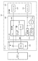
次に、図2を参照してプリンタ101の制御構成について説明する。図2は、第1の実施形態に係るプリンタ101の制御ブロックを示す図である。
Next, the control configuration of the
プリンタ101は、ホストコンピュータ230とネットワークを介して接続される。ホストコンピュータ230は、ネットワークを介してプリンタ101に印刷命令を送信する。プリンタ101は、ホストコンピュータ230からの印刷命令に従って印刷を実行する。
The
上述のように印刷を実行するために、プリンタ101は、コントローラ部201、エンジン部202及び低圧電源222を備える。コントローラ部201は、第1制御手段として機能し、プリンタ101を統括的に制御し、ホストコンピュータ230からの印刷命令を受信して、受信した印刷命令に従ってエンジン部202に印刷を実行させる。これらの制御を行うために、コントローラ部201は、CPU204を備える。
In order to execute printing as described above, the
エンジン部202は、第2制御手段として機能し、コントローラ部201からの命令に従って用紙に画像を形成する画像形成処理を制御する。具体的に、エンジン部202は、図1に示す各エンジンを制御して印刷を実行する。エンジン部202は、制御基板203、高圧電源219、ポリゴンモータ212、213、214、215及びモータ220を備える。制御基板203には、エンジン各部を制御するCPU210が搭載されている。
The
低圧電源222は、エンジン部の電源Vcc、モータ220、ポリゴンモータ212〜215及び高圧電源219などの各部ユニットへ電源を供給する。低圧電源222は、例えば、2つのコンバータ223、224を備えた電源ユニットであり、コンバータ223は省エネルギー状態(省エネルギーモード)においてもオンを維持する。一方、コンバータ224は省エネルギー状態時において、オフに設定される。もちろん、コンバータをオフにすることで消費電力を抑えることができる。本実施形態によれば、CPU210は、省エネルギー状態でオフにされる。CPU210は、図中のスリープ時OFF信号と表記する信号により、CPU210自身のVcc電源をオフに設定することができる。省エネルギー状態についての詳細は、後述する。
The low-
本実施形態において、CPU210をオフに設定する機能は、FETスイッチを使用している。このスイッチは、電源ラインをオンオフ可能であればFETスイッチに限定するものではない。また、CPU210のVcc電源のスイッチは、コントローラ部201から設定することもできる。したがって、本実施形態によれば、省エネルギー状態からの復帰時はコントローラ部201からエンジン部202のCPU210をオンに設定する。なお、このCPU210のVcc電源のFETは、PchのFETを使用する。これにより、プリンタ101の電源投入時には、コントローラ部201が起動していない状態であってもCPU210は起動することができる。
In the present embodiment, the function for setting the
コントローラ部201は、省エネルギー状態においてメモリアクセスを停止したりハードディスクドライブをオフにするなど多くの機能を停止させる。また、コントローラ部201のCPU204もクロックダウンを行いスタンバイ状態よりも機能ダウンしている。そのため、CPU204も省エネルギー状態から復帰するために、各部機能の立上げに時間が必要となり省エネルギー状態からの復帰時間に関しても工夫が必要となっている。
The
以下では、プリンタ101の動作状態について説明する。プリンタ101は、動作状態として、例えば、起動状態、スタンバイ状態、省エネルギー状態及び停止状態を有する。起動状態は、全ての基板が通電され、印刷を開始できる状態を示す。スタンバイ状態は、電源オンの状態で印刷を停止している場合を示す。このスタンバイ状態では、定着ユニット122の温度を印刷時よりも低い温度で保温する温度制御が行われる。印刷停止状態で保温する目的は、印刷を開始した際の印刷開始時間を早めるためである。スタンバイ状態で、予め定められた時間が経過すると、省エネルギー状態と呼ぶモードに遷移する。省エネルギー状態は、コントローラ部201の一部の機能を制限(停止)するとともに、エンジン部202の全ての機能を制限することで、待機時間の消費電力を低減することを目的とした状態を示す。停止状態は、プリンタ101の電源がオフに設定されている状態を示す。
Hereinafter, the operation state of the
本実施形態における省エネルギー状態では、スタンバイ状態と異なり、定着ユニット122への保温制御を中止する。また、本実施形態では、印刷コマンドを受け付けるコントローラ部の一部の制御回路のみを通電し、それ以外のCPU及びエンジン部202のCPUなどの通電を遮断する。コントローラ部201においては、ホストコンピュータ230とのインタフェースであるネットワークコントローラ部などの一部の回路を通電するのみで、CPU204、メモリ、ハードディスクドライブなど、消費電力の大きなデバイスの電源は遮断される。
In the energy saving state in this embodiment, unlike the standby state, the heat retention control to the fixing
省エネルギー状態からの復帰は、コントローラ部201の一部の回路がホストコンピュータ230又はユーザからのトリガを検出することで開始される。ユーザからのトリガで代表的なものは、プリンタ101の操作パネルに設けられた節電モードからの復帰キースイッチである。ホストコンピュータからのトリガは、主に印刷命令である。省エネルギー状態でも通電されている一部の回路は、印刷命令の受信をトリガに、CPU204の電源をオンにして起動することで、コントローラ部201の省エネルギー状態からの復帰が行われる。
The return from the energy saving state is started when a part of the circuit of the
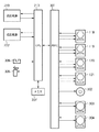
次に、図3Aを参照して、エンジン部202の詳細な制御構成について説明する。図3Aは、第1の実施形態に係るエンジン部202の画像形成に関する制御ブロックを示す図である。ここでは、CPU210が制御する起動処理、復帰処理及び各ユニットの構成を示す。ここで、起動処理とは、停止状態にあるエンジン部202を起動させるための処理を示す。また、復帰処理は、省エネルギー状態にあるエンジン部202を起動させるための処理を示す。起動処理及び復帰処理の詳細については後述するが、復帰処理は、起動処理の一部を含む。したがって、復帰処理は、起動処理と比較して簡易化されており、処理に必要とする時間が短縮される。
Next, a detailed control configuration of the
CPU210は、ポリゴンミラー、モータ及びレーザを含む各色用の光学ユニット118〜121に接続され、感光ドラム面上にレーザを走査し、所望の潜像を描くために各色用の光学ユニットの制御を行う。また、CPU210は、給紙モータ302に接続され、用紙の搬送を制御する。また、CPU210は、給紙ローラの駆動開始に使用する給紙ソレノイド305に接続され、用紙の給紙を制御する。また、CPU210は、用紙が所定位置にセットされているか否かを検知する紙有無センサ306に接続され、紙有無センサ306の信号に従って用紙の搬送を制御する。また、CPU210は、電子写真プロセスに必要な1次帯電、現像、1次転写、2次転写バイアスを制御する高圧電源219に接続される。また、CPU210は、感光ドラム及び転写ローラを駆動するドラム駆動モータ303と、転写ベルト及び定着ユニットのローラを駆動するためのベルト駆動モータ304と、定着ユニット及び低圧電源222を制御する。さらに、CPU210によってサーミスタ(図示せず)により温度をモニタし、定着温度を一定に保つ制御がなされる。
The
詳細には、CPU210は、ASIC301に接続され、ASIC301にCPU210の指示に基づいて光学ユニット118〜121内部のモータ速度制御、給紙モータの速度制御を行わせる。モータの速度制御は、モータ(図示せず)からのタック信号を検出して、タック信号の間隔が所定の時間となるようモータに対して出力される加速信号又は減速信号によって行われる。複数のモータの速度制御を行うため、ソフトウエアによる制御よりは、制御回路としてASIC301のハードウエアによる回路で構成した方が、CPU210の制御負荷の低減が図れる。
Specifically, the
CPU210は、ホストコンピュータ230からの印刷命令を受信すると、紙有無センサ306によって用紙の有無を判断する。紙有りの場合、CPU210は、給紙モータ302、ドラム駆動モータ303、ベルト駆動モータ304を駆動するとともに、給紙ソレノイド305を駆動して用紙を所定位置まで搬送する。用紙の先端がトップセンサ123で検知されると、CPU210は、画像形成タイミングを決定し、画像と用紙との位置関係を補正する。
When the
以下では、図3Bを参照して、起動処理及び復帰処理を制御するためのCPU204、210の制御機能について説明する。図3Bは、第1の実施形態に係るコントローラ部201及びエンジン部202の起動処理及び復帰処理に関する制御ブロックを示す図である。以下では、主に本発明に関する制御ブロックについての説明を記載する。したがって、CPU204、210は、他の制御ブロックを含んで構成されてもよい。
Hereinafter, the control functions of the
コントローラ部201に含まれるCPU204は、送信部311、受信部312、起動部313及び復帰部314を備える。送信部311は、エンジン部202に対するコマンドを送信する。受信部312は、ネットワークを介して接続されたホストコンピュータ230から印刷命令を受信する。また、受信部312は、エンジン部202から送信されるステータスコマンドを受信する。ステータスコマンドは、送信部311が送信するコマンドに対する応答である。起動部313は、停止状態から起動された場合、即ち、電源投入時に、コントローラ部201の起動処理を行う。復帰部314は、省エネルギー状態から起動された場合のコントローラ部201の復帰処理を行う。なお、コントローラ部201での省エネルギー状態は、一部の機能が既に起動している。そのため、コントローラ部201は、何れの状態(停止状態又は省エネルギー状態)から起動されたかを起動時に認識することができ、容易に起動処理又は復帰処理を選択して実行することができる。
The
エンジン部202に含まれるCPU210は、送信部321、受信部322、起動部323、復帰部324、調整部325及び画像形成部327を備える。送信部321は、コントローラ部201から送信されたコマンドに対するステータスコマンドをコントローラ部201に送信する。受信部322は、コントローラ部201から送信されたコマンドを受信する。画像形成部327は、図3Aで説明した処理を統括的に制御し、用紙に画像を形成する。
The
起動部323は、起動手段として機能し、停止状態にあるエンジン部202を起動させるための起動処理を実行する。復帰部324は、復帰手段として機能し、省エネルギー状態にあるエンジン部202を起動させる処理であって、上述の起動処理の一部となる復帰処理を実行する。なお、エンジン部202での省エネルギー状態は、停止状態と同様にCPU210が通電されていない(即ち、オフの状態にある。)。したがって、エンジン部202では、起動時に、何れの状態から起動されたか判断できない。本実施形態では、この問題を解決するために、起動調整手段として機能する調整部325が設けられている。
The
調整部325は、停止状態又は省エネルギー状態の何れの状態から起動されたかに関わらず、まず、復帰部324による復帰処理を実行させる。ここで、この復帰処理は、コントローラ部201で行われる起動処理又は復帰処理と同時に行われる。このように、本実施形態に係るエンジン部202は、コントローラ部201の起動処理が完了した後に、起動処理又は復帰処理を実行するわけではなく、コントローラ部201の起動処理と同時に復帰処理を実行する。したがって、本実施形態に係るプリンタ101は、総合的に起動処理を短縮することができる。
Regardless of whether the
その後、調整部325は、復帰処理が完了すると、自身が備える待機部326によって処理を待機させる。具体的に、待機部326は、待機手段として機能し、コントローラ部201から通知される起動情報を受信するまで処理を待機させる。ここで、起動情報とは、起動前のプリンタ101の動作状態を示す情報である。例えば、起動時のプリンタ101の動作状態が停止状態であるか、又は、省エネルギー状態であるかを示す。起動情報を受信すると、調整部325は、起動情報が停止状態を示す場合に起動部323による起動処理を実行させる。ここで、調整部325は、復帰処理と重複する起動処理の処理を省略するように起動部323に対して指示することが望ましい。これにより、重複した処理を避けることができ、起動処理を効率化することができる。
Thereafter, when the restoration process is completed, the
次に、図4を参照して、エンジン部202の復帰処理について説明する。図4は、エンジン部202の復帰処理の手順を示すフローチャートである。CPU210は、起動前におけるプリンタ101の動作状態が停止状態又は省エネルギー状態に関わらず、以下の処理を実行する。なお、以下で説明する処理は、復帰処理の一例であり、復帰処理の内容を限定するわけではない。即ち、復帰処理は、各プリンタの仕様に合わせて設定される。
Next, the return process of the
ステップS401において、復帰部324は、当接、離間動作部の位置を確認する。当接、離間動作部とは、転写ローラ110〜113を転写ベルト105に当接又は離間させる動作部を示す。当接、離間動作部は、画像形成時に転写ローラ110〜113を転写ベルト105に当接させ、感光ドラム106〜109に形成されたトナー像を用紙に転写させる。即ち、転写ローラ110〜113と感光ドラム106〜109によって用紙を狭持搬送することにより、用紙にトナー像を転写させる。一方、画像形成時以外は、転写ローラ110〜113を転写ベルト105から離間させる。これは、転写ローラ110〜113及び感光ドラム106〜109の不要な摩耗を抑制するために行われる。
In step S401, the
ステップS402において、復帰部324は、外部装置、オプション装置の接続を確認する。例えば、オプション装置として、用紙カセット102がプリンタ101に確認されているか否かを判定し、画像形成動作を実行することができるか否かを判定する。
In step S402, the
ステップS403において、復帰部324は、接続されている外部装置及びオプション装置との通信を開始する。さらに、ステップS404において、復帰部324は、コントローラ部201との接続を確認する。
In step S403, the
その後、ステップS405において、復帰部324は、不揮発メモリのデータチェックする。さらに、ステップS406において、定着ユニット122の加温制御を行う。停止状態又は省エネルギー状態では、定着ユニット122へ加温制御が停止されているため、画像形成動作の準備として加温制御をする必要がある。
Thereafter, in step S405, the
このように、通常、省エネルギー状態からの復帰時にも、スタンバイ状態になるまでに時間を要する。したがって、本実施形態では、コントローラ部201のCPU204の起動を待つことなく、省エネルギー状態からの復帰処理を行うことで、省エネルギー状態からの復帰時間を短縮させることができる。
As described above, it usually takes time to return to the standby state even when returning from the energy saving state. Therefore, in this embodiment, the return time from the energy saving state can be shortened by performing the return processing from the energy saving state without waiting for the activation of the
次に、図5を参照して、エンジン部202の起動処理について説明する。図5は、エンジン部202の起動処理の手順を示すフローチャートである。以下では、図4で説明した復帰処理と重複する処理については同一の番号を付し、説明を省略する。なお、図中の「(※)」は、復帰処理と同一の処理を示す。
Next, the startup process of the
ステップS501において、起動部323は、各ユニット(エンジン)の有無を確認し、各ユニットの初期化処理を行う。さらに、ステップS502において、起動部323は、温度検出など環境チェックを行う。この環境チェックの結果に基づいて、エンジン部202は、画像形成時の各ユニットの設定値を調整する。
In step S501, the
ステップS503において、起動部323は、プリンタ101内の用紙の有無を検出する。これは、プリンタ101内の搬送路に用紙が残留しているか否かを判定する。さらに、ステップS504において、起動部323は、プリンタ101内のクリーニング処理を行う。例えば、S503で残留している用紙を検出した場合、エンジン部202は、残留している用紙をプリンタ101の機外へ排出する。
In step S <b> 503, the
次に、図6を参照して、本実施形態に係る起動処理及び復帰処理について説明する。図6は、第1の実施形態に係る起動処理及び復帰処理の処理手順を示すフローチャートである。以下では、図4及び図5と重複する処理については同一の番号を付し、説明を省略する。 Next, with reference to FIG. 6, the start-up process and the return process according to the present embodiment will be described. FIG. 6 is a flowchart illustrating the processing procedure of the startup process and the return process according to the first embodiment. In the following, the same processes as those in FIGS. 4 and 5 are denoted by the same reference numerals, and the description thereof is omitted.
エンジン部202のCPU210が通電されると、まず、調整部325は、復帰処理であるS401乃至S406の処理を復帰部324に実行させる。復帰処理が終了すると、ステップS601において、調整部325は、コントローラ部201からのコマンドを受信するまで処理を待機させる。さらに、コントローラ部201のCPU204が起動した後にコマンドを受信すると、調整部325は、受信したコマンドが電源ONコマンドであるか、又は、印刷コマンドであるかを判定する。ここで、電源ONコマンドである場合は、起動前のプリンタ101の動作状態が停止状態であったことを示す。一方、印刷コマンドである場合は、起動前のプリンタ101の動作状態が省エネルギー状態であったことを示す。
When the
即ち、調整部325は、電源ONコマンドを受信すると引き続き起動処理を実行させ、印刷コマンドを受信すると起動時の処理を終了させる。具体的に、電源ONコマンドを受信すると、調整部325は、処理をS501に遷移させ、起動部323にS501乃至S504の処理を実行させる。
In other words, the
上述したように、本実施形態に係るエンジン部202のCPU210は、自身が通電されると、省エネルギー状態からの復帰処理を実行する。その後、コントローラ部のCPU204が起動するまで待機する。さらに、コントローラ部201のCPU204が起動した後に、当該コントローラ部201から通知される起動情報に従って、必要であれば起動処理を実行する。これにより、省エネルギー状態からの復帰に関しては時間を短縮することができる。これらの起動時の処理の調整は、調整部325によって制御される。
As described above, when the
また、起動処理の一部の処理(※)は、省エネルギー状態からの復帰処理と同一である。即ち、電源投入時の起動処理として、調整部325は、復帰処理を前もって行っていた場合には、※印の処理を省略した起動処理を実行させる。このように制御することで、起動処理についても、必要な処理のみが実行されるため処理時間を短縮することができる。重複した処理を避けることは、装置の稼働時間を減らすため、装置寿命を延ばすという観点でも重要である。装置寿命の延命により、ユーザに対して低コストのプリンタを提供できる。ここで装置とは、例えば、コントローラ部201のハードディスクドライブ、又は、エンジン部202のモータ類、ローラ、ベルト、感光ドラムユニット、現像剤などを示す。
Further, a part of the start process (*) is the same as the return process from the energy saving state. That is, as a startup process at the time of power-on, the
以上説明したように、本実施形態に係る画像形成装置は、エンジン部202のCPU210が通電されると、停止状態又は省エネルギー状態の何れの状態から起動されたかに関わらず、まず、復帰処理を実行する。その後、電源投入時の起動であることが判明すると、画像形成装置は、起動処理を実行する。これにより、本画像形成装置は、コントローラ部201の起動処理と同時に、エンジン部202の復帰処理を実行することができ、省エネルギー状態からの復帰処理を高速化することができる。
As described above, when the
なお、本発明は、上記実施形態に限らず様々な変形が可能である。例えば、本画像形成装置は、電源投入時の起動であることが判明すると、起動処理のうち、前もって実行している復帰処理の内容と重複しない処理を実行してもよい。これにより、本画像形成装置は、電源投入時の処理についても高速化することができる。 The present invention is not limited to the above embodiment, and various modifications can be made. For example, when it is determined that the image forming apparatus is activated when the power is turned on, the image forming apparatus may execute a process that does not overlap with the contents of the restoration process that has been performed in advance. As a result, the image forming apparatus can also speed up the process when the power is turned on.
[第2の実施形態]
次に、図7A乃至図8を参照して、第2の実施形態について説明する。本実施形態は、動作状態を停止状態に遷移させる終了処理の中で、エンジン部202のCPU210が正常終了したか否かを示すフラグをメモリに格納する。これにより、本実施形態に係るプリンタ101は、起動時に当該メモリを参照することで、起動処理又は復帰処理を選択して実行する。
[Second Embodiment]
Next, a second embodiment will be described with reference to FIGS. 7A to 8. In the present embodiment, a flag indicating whether or not the
第1の実施形態では、エンジン部202におおいて、電源投入による起動又は省エネルギー状態からの復帰に関わらず、まず、省エネルギー状態からの復帰処理を実行し、電源投入による起動だった場合には残りの起動処理を追加で行うものであった。これは、省エネルギー状態からの復帰処理と、電源投入による起動処理を完全に分離しなければならない。ところが、復帰処理の中には、コントローラ部201が起動した後でないと完了しない処理が含まれる場合がある。厳密に言えば、起動処理が終わった後に、復帰処理の一部を行うケースもある。例えば、コントローラ部201がアクセスする不揮発メモリや表示パネルの動作チェックなどはコントローラ部201が起動した後に行われることが望ましい。したがって、本実施形態は、第1の実施形態と異なり、エンジン部202の起動処理と復帰処理とをそれぞれ一連の流れの中で行うことを想定している。
In the first embodiment, in the
図7Aは、第2の実施形態に係るプリンタ101の制御ブロックを示す図である。ここでは、第1の実施形態と異なる部分についてのみ説明を記載する。以下では、図2と同様の構成要素について同一の番号を付し、説明を省略する。
FIG. 7A is a diagram illustrating a control block of the
本実施形態に係る制御基板203には、CPU210からアクセス可能な不揮発メモリ701を備える。不揮発メモリ701は、記憶手段として機能し、エンジン部202が停止状態に遷移した段階で正常終了を示すフラグを格納する。
The
図7Bは、第2の実施形態に係るコントローラ部201及びエンジン部202の起動処理及び復帰処理に関する制御ブロックを示す図である。以下では、図3Bと同様の構成要素について同一の番号を付し、説明を省略する。
FIG. 7B is a diagram illustrating control blocks related to the startup process and the return process of the
CPU210は、第1の実施形態と異なり、書込部702、及び、調整部325の代わりとなる選択部703を備える。書込部702は、印刷が可能な起動状態から停止状態に遷移する前に、起動情報として、不揮発メモリ701に停止状態を示す情報を書き込む。即ち、書込部702は、その後起動された時点で、起動前の状態を示す情報を履歴として残す。選択部703は、まず、プリンタ101が起動されると、不揮発メモリ701に停止状態を示す情報が書き込まれているか否かを判定する。ここで、停止状態を示す情報が不揮発メモリ701に書き込まれている場合、選択部703は、コントローラ部201の起動処理と同時に、電源投入時の起動処理を選択して実行させる。一方、停止状態を示す情報が書き込まれていない場合、選択部703は、コントローラ部201の起動処理と同時に、省エネルギー状態からの復帰処理を選択して実行させる。
Unlike the first embodiment, the
図8は、第2の実施形態に係る起動処理及び復帰処理の処理手順を示すフローチャートである。以下では、図4及び図5と重複する処理については同一の番号を付し、説明を省略する。 FIG. 8 is a flowchart illustrating the processing procedure of the startup process and the return process according to the second embodiment. In the following, the same processes as those in FIGS. 4 and 5 are denoted by the same reference numerals, and the description thereof is omitted.
エンジン部202が起動される(即ち、エンジン部202が通電される)と、ステップS801において、選択部703は、エンジン部202の起動前に、プリンタ101の動作状態が停止状態であったか否かを判定する。具体的に、選択部703は、不揮発メモリ701に停止状態を示す情報が格納されているか否かを判定する。ここで、不揮発メモリ701に停止状態を示す情報が格納されていない場合、選択部703は、処理をS802に遷移させる。一方、不揮発メモリ701に停止状態を示す情報が格納されている場合、選択部703は、処理をS804に遷移させる。ステップS804において、選択部703は、起動部323に起動処理を実行させる。ここで、S804の処理は、図5に示すS501乃至S504の処理と同様である。
When the
ステップS802において、選択部703は、復帰部324に復帰処理を実行させる。ここで、S802の処理は、図4に示すS401乃至S406の処理と同様である。その後、ステップS803において、選択部703は、コントローラ部201から通知される起動情報が停止状態を示すコマンド(電源ONコマンド)であるか、省エネルギー状態を示すコマンド(印刷コマンド)であるかを判定する。電源ON起動コマンドであった場合、選択部703は、不揮発メモリ701の情報が誤っていいたと判断し、処理をS804に遷移させて起動処理を実行させる。一方、印刷コマンドであった場合、選択部703は、起動時の処理を終了させる。ここでの起動処理においては、第1の実施形態と同様に、復帰処理の内容と重複する処理については省略することが望ましい。
In step S802, the
このように、本実施形態に係るエンジン部202は、電源投入時の起動処理に関して、復帰処理を実行した後に、コントローラ部201の起動を待つことなく、コントローラ部201の起動処理と同時に実行する。したがって、本実施形態に係るプリンタ101は、第1の実施形態の起動処理と比較して、起動処理についてより高速化することができる。また、上述したように、復帰処理又は起動処理を一連の流れの中で実行するため、コントローラ部201の起動終了後に実行する処理を後回しにすることもできる。よって、復帰処理と、起動処理とを完全に分離できないシステムにおいても本発明を適用することができ、汎用性を向上しうる。
As described above, the
[第3の実施形態]
次に、図9を参照して、第3の実施形態について説明する。本実施形態は、第2の実施形態と異なり、プリンタ101の動作状態が起動状態から省エネルギー状態に遷移する前に、省エネルギー状態を示す情報を不揮発メモリ701に書き込む。したがって、本実施形態に係るプリンタ101の制御構成は、図7A及び図7Bと同様である。しかし、書込部702は、起動状態から省エネルギー状態に遷移する前に、起動情報として、不揮発メモリ701に省エネルギー状態を示す情報を書き込む。したがって、選択部703は、不揮発メモリ701に省エネルギー状態を示す情報が書き込まれている否かを判定することにより、起動処理又は復帰処理を選択して実行することとなる。
[Third Embodiment]
Next, a third embodiment will be described with reference to FIG. In the present embodiment, unlike the second embodiment, information indicating the energy saving state is written in the
図9は、第3の実施形態に係る起動処理及び復帰処理の処理手順を示すフローチャートである。以下では、図4及び図5と重複する処理については同一の番号を付し、説明を省略する。 FIG. 9 is a flowchart illustrating a processing procedure of a start process and a return process according to the third embodiment. In the following, the same processes as those in FIGS. 4 and 5 are denoted by the same reference numerals, and the description thereof is omitted.
エンジン部202が起動される(即ち、エンジン部202が通電される)と、ステップS901において、選択部703は、エンジン部202の起動前に、プリンタ101の動作状態が省エネルギー状態であったか否かを判定する。具体的に、選択部703は、不揮発メモリ701に省エネルギー状態を示す情報が格納されているか否かを判定する。ここで、不揮発メモリ701に省エネルギー状態を示す情報が格納されていない場合、選択部703は、処理をS902に遷移させる。一方、不揮発メモリ701に省エネルギー状態を示す情報が格納されている場合、選択部703は、処理をS904に遷移させる。ステップS904において、選択部703は、起動部323に起動処理を実行させる。ここで、S904の処理は、図5に示すS501乃至S504の処理と同様である。
When the
ステップS902において、選択部703は、復帰部324に復帰処理を実行させる。ここで、S902の処理は、図4に示すS401乃至S406の処理と同様である。その後、ステップS903において、選択部703は、コントローラ部201から通知される起動情報が停止状態を示すコマンド(電源ONコマンド)であるか、省エネルギー状態を示すコマンド(印刷コマンド)であるかを判定する。電源ON起動コマンドであった場合、選択部703は、不揮発メモリ701の情報が誤っていいたと判断し、処理をS804に遷移させて起動処理を実行させる。一方、印刷コマンドであった場合、選択部703は、起動時の処理を終了させる。ここでの起動処理においては、第1の実施形態と同様に、復帰処理の内容と重複する処理については省略することが望ましい。
In step S902, the
このように、本実施形態に係るエンジン部202は、電源投入時の起動処理に関して、復帰処理を実行した後に、コントローラ部201の起動を待つことなく、コントローラ部201の起動処理と同時に実行する。したがって、本実施形態に係るプリンタ101は、第1の実施形態の起動処理と比較して、起動処理についてより高速化することができる。また、上述したように、復帰処理又は起動処理を一連の流れの中で実行するため、コントローラ部201の起動終了後に実行する処理を後回しにすることもできる。よって、復帰処理と、起動処理とを完全に分離できないシステムにおいても本発明を適用することができ、汎用性を向上しうる。
As described above, the
なお、第2及び第3の実施形態における不揮発メモリ701を用いた状態記憶は、低コストで実現できるので最適な手段であるが、他の手段として電気回路を用いたラッチ回路方式でも類似の構成は実現できる。この場合のラッチ回路方式の例としてはDラッチなどを使用するのが簡単である。この場合、電源オフになると電気回路式のラッチ回路はデフォルト状態に戻ってしまうので、省エネルギー状態の履歴を残す論理に対してラッチをセットすることが構成を簡単にできる。
The state storage using the
101:プリンタ
201:コントローラ部
202:エンジン部
203:制御基板
204、210:CPU
212、213、214、215:ポリゴンモータ
219:高圧電源
220:モータ
222:低圧電源
223、224:コンバータ
230:ホストコンピュータ
101: Printer 201: Controller unit 202: Engine unit 203:
212, 213, 214, 215: Polygon motor 219: High voltage power supply 220: Motor 222: Low
Claims (4)
前記停止状態にある前記第2制御手段を起動させるための起動処理を実行する起動手段と、
前記省エネルギー状態にある前記第2制御手段を起動させる復帰処理であって、前記起動処理の一部となる前記復帰処理を実行する復帰手段と、
前記停止状態又は前記省エネルギー状態の何れの状態から起動されたかに関わらず、前記第1制御手段の起動時の処理と同時に前記復帰手段による復帰処理を実行させ、前記第1制御手段が起動した後に前記第2制御手段に対して通知される起動前の動作状態を示す起動情報が前記停止状態を示す場合に前記起動手段による起動処理を実行させる起動調整手段と、を備えており、
前記起動調整手段は、
前記復帰処理を実行させた後に、前記第1制御手段から通知される前記起動情報を受信するまで前記起動手段による起動処理を待機させる待機手段を備えており、
前記起動処理を実行させる場合には、該起動処理のうち、既に実行されている復帰処理と重複しない処理のみを実行させることを特徴とする画像形成装置。 A first control unit that comprehensively controls the apparatus; and a second control unit that controls an image forming process for forming an image on a recording material in accordance with an instruction from the first control unit. As the operation state of the second control means, an energy saving state in which power consumption is limited by stopping a part of the functions of the first control means and all the functions of the second control means, the first control means, and the An image forming apparatus having a stopped state in which all functions of the second control unit are stopped,
An activation means for executing an activation process for activating the second control means in the stopped state;
A return process for starting the second control means in the energy-saving state, the return means executing the return process as a part of the start process;
Regardless of whether it is activated from the stopped state or the energy saving state, after the first control means is activated, the restoration process by the restoration means is executed simultaneously with the process at the time of activation of the first control means. Start adjustment means for executing start processing by the start means when the start information indicating the operation state before start notified to the second control means indicates the stop state , and
The activation adjusting means includes
A standby means for waiting for the activation process by the activation means until the activation information notified from the first control means is received after the return process is executed;
In the case of executing the startup process, only the process that does not overlap with the already-executed return process is executed among the startup processes .
前記第1制御手段から通知される前記起動情報が前記省エネルギー状態を示す場合に、前記起動手段による起動処理のうち、前記復帰処理と重複しない処理を実行させないことを特徴とする請求項1に記載の画像形成装置。 The activation adjusting means includes
2. The process according to claim 1, wherein when the activation information notified from the first control unit indicates the energy saving state, a process that does not overlap with the return process is not executed among the activation processes performed by the activation unit. Image forming apparatus.
前記停止状態にある前記第2制御手段を起動させるための起動処理と、前記省エネルギー状態にある前記第2制御手段を起動させる復帰処理であって、前記起動処理の一部となる前記復帰処理と、を有し、
前記停止状態又は前記省エネルギー状態の何れの状態から起動されたかに関わらず、前記第1制御手段の起動時の処理と同時に前記復帰処理を実行するステップと、
前記第1制御手段が起動した後に前記第2制御手段に対して通知される起動前の動作状態を示す起動情報が前記停止状態を示す場合に前記起動処理を実行するステップと、を含み、
前記復帰処理を実行した後に、前記第1制御手段から通知される前記起動情報を受信するまで前記起動処理を待機させ、前記起動処理を実行する場合には、該起動処理のうち、既に実行した復帰処理と重複しない処理のみを実行することを特徴とする制御方法。 A first control unit that comprehensively controls the apparatus; and a second control unit that controls an image forming process for forming an image on a recording material in accordance with an instruction from the first control unit. As the operation state of the second control means, an energy saving state in which power consumption is limited by stopping a part of the functions of the first control means and all the functions of the second control means, the first control means, and the A control method for an image forming apparatus having a stopped state in which all functions of the second control unit are stopped,
An activation process for activating the second control means in the stopped state, and a restoration process for activating the second control means in the energy saving state, the restoration process being a part of the activation process ; Have
Regardless of whether it is activated from the stopped state or the energy-saving state, the step of executing the return process simultaneously with the process at the time of activation of the first control means ;
Comprises the steps that perform the activation process when the activation information indicating an operation state before activation to be notified shows the stopped state to the second control means after starting said first control means,
After executing the restoration process, when the activation process is waited until the activation information notified from the first control means is received and the activation process is executed, the activation process has already been performed. A control method characterized by executing only processing that does not overlap with return processing .
Priority Applications (1)
| Application Number | Priority Date | Filing Date | Title |
|---|---|---|---|
| JP2007244445A JP5247098B2 (en) | 2007-09-20 | 2007-09-20 | Image forming apparatus and control method thereof |
Applications Claiming Priority (1)
| Application Number | Priority Date | Filing Date | Title |
|---|---|---|---|
| JP2007244445A JP5247098B2 (en) | 2007-09-20 | 2007-09-20 | Image forming apparatus and control method thereof |
Publications (3)
| Publication Number | Publication Date |
|---|---|
| JP2009075369A JP2009075369A (en) | 2009-04-09 |
| JP2009075369A5 JP2009075369A5 (en) | 2010-11-04 |
| JP5247098B2 true JP5247098B2 (en) | 2013-07-24 |
Family
ID=40610382
Family Applications (1)
| Application Number | Title | Priority Date | Filing Date |
|---|---|---|---|
| JP2007244445A Active JP5247098B2 (en) | 2007-09-20 | 2007-09-20 | Image forming apparatus and control method thereof |
Country Status (1)
| Country | Link |
|---|---|
| JP (1) | JP5247098B2 (en) |
Families Citing this family (1)
| Publication number | Priority date | Publication date | Assignee | Title |
|---|---|---|---|---|
| JP2012153033A (en) * | 2011-01-27 | 2012-08-16 | Ricoh Co Ltd | Image forming apparatus and program |
Family Cites Families (8)
| Publication number | Priority date | Publication date | Assignee | Title |
|---|---|---|---|---|
| JP3651758B2 (en) * | 1998-12-25 | 2005-05-25 | 株式会社リコー | Energy saving return method and recording device using the same |
| JP3893910B2 (en) * | 2001-07-12 | 2007-03-14 | 富士ゼロックス株式会社 | Electronic device and control method thereof |
| JP2003186357A (en) * | 2001-12-20 | 2003-07-04 | Copyer Co Ltd | Method for returning from energy saving and image forming apparatus |
| JP2003241582A (en) * | 2002-02-20 | 2003-08-29 | Ricoh Co Ltd | Image forming apparatus |
| JP2005010602A (en) * | 2003-06-20 | 2005-01-13 | Fuji Xerox Co Ltd | Image forming apparatus |
| JP2005115478A (en) * | 2003-10-03 | 2005-04-28 | Fuji Xerox Co Ltd | Control system |
| JP4796442B2 (en) * | 2005-07-05 | 2011-10-19 | 株式会社リコー | Image forming apparatus and control method thereof |
| JP4972305B2 (en) * | 2005-11-10 | 2012-07-11 | 株式会社リコー | Image forming apparatus and energy saving return method |
-
2007
- 2007-09-20 JP JP2007244445A patent/JP5247098B2/en active Active
Also Published As
| Publication number | Publication date |
|---|---|
| JP2009075369A (en) | 2009-04-09 |
Similar Documents
| Publication | Publication Date | Title |
|---|---|---|
| JP4796442B2 (en) | Image forming apparatus and control method thereof | |
| KR101669443B1 (en) | Image forming apparatus capable of shortening time required for start-up, control method therefor, and storage medium | |
| US7751755B2 (en) | Image forming apparatus | |
| JP2008300922A (en) | Image processor, control method of image processor, control program, and recording medium | |
| US9083824B2 (en) | Image forming apparatus for detecting an abnormality | |
| JP5489625B2 (en) | Image forming apparatus | |
| JP4402083B2 (en) | Image forming apparatus | |
| JP2008065470A (en) | Control method and control device for image recording device, and control program | |
| JP2006021527A (en) | Image formation device and control method of the same | |
| JP4715255B2 (en) | Image forming apparatus and program | |
| JP5247098B2 (en) | Image forming apparatus and control method thereof | |
| JP4233517B2 (en) | Image forming apparatus | |
| JP2007310365A (en) | Method for controlling image forming apparatus | |
| EP2138904B1 (en) | Image forming apparatus, control method for image forming apparatus, and storage medium | |
| JPH11268380A (en) | Printing device and printing device control method | |
| JP6061531B2 (en) | Print control apparatus, print control method, and program | |
| JP2003015478A (en) | Image forming device | |
| JP2011065011A (en) | Image forming apparatus and method for controlling the same | |
| JP2012137802A (en) | Information processing device | |
| JP2010002708A (en) | Image forming apparatus | |
| JP4650121B2 (en) | Image forming apparatus and method for controlling image forming apparatus | |
| JP2006272636A (en) | Image forming apparatus, its control method, and program | |
| JP5188196B2 (en) | Paper transport device, paper transport method, and paper transport program for image forming apparatus | |
| JP6225882B2 (en) | Electronic apparatus and image forming apparatus | |
| JP2006201262A (en) | Image forming system |
Legal Events
| Date | Code | Title | Description |
|---|---|---|---|
| A521 | Written amendment |
Free format text: JAPANESE INTERMEDIATE CODE: A523 Effective date: 20100921 |
|
| A621 | Written request for application examination |
Free format text: JAPANESE INTERMEDIATE CODE: A621 Effective date: 20100921 |
|
| A977 | Report on retrieval |
Free format text: JAPANESE INTERMEDIATE CODE: A971007 Effective date: 20120712 |
|
| A131 | Notification of reasons for refusal |
Free format text: JAPANESE INTERMEDIATE CODE: A131 Effective date: 20120717 |
|
| A521 | Written amendment |
Free format text: JAPANESE INTERMEDIATE CODE: A523 Effective date: 20120913 |
|
| TRDD | Decision of grant or rejection written | ||
| A01 | Written decision to grant a patent or to grant a registration (utility model) |
Free format text: JAPANESE INTERMEDIATE CODE: A01 Effective date: 20130311 |
|
| A61 | First payment of annual fees (during grant procedure) |
Free format text: JAPANESE INTERMEDIATE CODE: A61 Effective date: 20130409 |
|
| R151 | Written notification of patent or utility model registration |
Ref document number: 5247098 Country of ref document: JP Free format text: JAPANESE INTERMEDIATE CODE: R151 |
|
| FPAY | Renewal fee payment (event date is renewal date of database) |
Free format text: PAYMENT UNTIL: 20160419 Year of fee payment: 3 |