JP5242401B2 - Method and apparatus for forming microstructured fibers - Google Patents
Method and apparatus for forming microstructured fibers Download PDFInfo
- Publication number
- JP5242401B2 JP5242401B2 JP2008534818A JP2008534818A JP5242401B2 JP 5242401 B2 JP5242401 B2 JP 5242401B2 JP 2008534818 A JP2008534818 A JP 2008534818A JP 2008534818 A JP2008534818 A JP 2008534818A JP 5242401 B2 JP5242401 B2 JP 5242401B2
- Authority
- JP
- Japan
- Prior art keywords
- extrudable material
- mold
- forming
- passage
- chamber
- Prior art date
- Legal status (The legal status is an assumption and is not a legal conclusion. Google has not performed a legal analysis and makes no representation as to the accuracy of the status listed.)
- Active
Links
- 238000000034 method Methods 0.000 title claims description 56
- 239000000835 fiber Substances 0.000 title claims description 38
- 239000000463 material Substances 0.000 claims description 86
- 238000001125 extrusion Methods 0.000 claims description 37
- 230000004888 barrier function Effects 0.000 claims description 33
- 238000010438 heat treatment Methods 0.000 claims description 9
- 230000008859 change Effects 0.000 claims description 5
- 230000000149 penetrating effect Effects 0.000 claims 2
- PCHJSUWPFVWCPO-UHFFFAOYSA-N gold Chemical compound [Au] PCHJSUWPFVWCPO-UHFFFAOYSA-N 0.000 claims 1
- 239000010931 gold Substances 0.000 claims 1
- 229910052737 gold Inorganic materials 0.000 claims 1
- 239000002184 metal Substances 0.000 claims 1
- 229910052751 metal Inorganic materials 0.000 claims 1
- 230000008569 process Effects 0.000 description 22
- 238000004519 manufacturing process Methods 0.000 description 13
- 239000011521 glass Substances 0.000 description 12
- 239000013307 optical fiber Substances 0.000 description 11
- 238000013461 design Methods 0.000 description 9
- VYPSYNLAJGMNEJ-UHFFFAOYSA-N Silicium dioxide Chemical compound O=[Si]=O VYPSYNLAJGMNEJ-UHFFFAOYSA-N 0.000 description 8
- 229920000642 polymer Polymers 0.000 description 7
- 230000003287 optical effect Effects 0.000 description 6
- 230000015572 biosynthetic process Effects 0.000 description 5
- 238000005266 casting Methods 0.000 description 5
- 238000000465 moulding Methods 0.000 description 4
- 239000002070 nanowire Substances 0.000 description 4
- 239000000377 silicon dioxide Substances 0.000 description 4
- 238000007711 solidification Methods 0.000 description 4
- 230000008023 solidification Effects 0.000 description 4
- 230000008901 benefit Effects 0.000 description 3
- 238000004891 communication Methods 0.000 description 3
- 239000000178 monomer Substances 0.000 description 3
- PXHVJJICTQNCMI-UHFFFAOYSA-N nickel Substances [Ni] PXHVJJICTQNCMI-UHFFFAOYSA-N 0.000 description 3
- 238000006116 polymerization reaction Methods 0.000 description 3
- 238000001816 cooling Methods 0.000 description 2
- 239000006185 dispersion Substances 0.000 description 2
- 238000007527 glass casting Methods 0.000 description 2
- 238000011065 in-situ storage Methods 0.000 description 2
- 238000002844 melting Methods 0.000 description 2
- 230000008018 melting Effects 0.000 description 2
- 229910052759 nickel Inorganic materials 0.000 description 2
- 238000012545 processing Methods 0.000 description 2
- 230000003746 surface roughness Effects 0.000 description 2
- 238000003466 welding Methods 0.000 description 2
- 229910000851 Alloy steel Inorganic materials 0.000 description 1
- KRHYYFGTRYWZRS-UHFFFAOYSA-M Fluoride anion Chemical compound [F-] KRHYYFGTRYWZRS-UHFFFAOYSA-M 0.000 description 1
- 230000002547 anomalous effect Effects 0.000 description 1
- 238000010420 art technique Methods 0.000 description 1
- 230000005540 biological transmission Effects 0.000 description 1
- 150000004770 chalcogenides Chemical class 0.000 description 1
- 238000010276 construction Methods 0.000 description 1
- 238000011109 contamination Methods 0.000 description 1
- 238000005260 corrosion Methods 0.000 description 1
- 230000007797 corrosion Effects 0.000 description 1
- 238000013500 data storage Methods 0.000 description 1
- 230000007123 defense Effects 0.000 description 1
- 238000006073 displacement reaction Methods 0.000 description 1
- 238000009826 distribution Methods 0.000 description 1
- 229920006240 drawn fiber Polymers 0.000 description 1
- 230000000694 effects Effects 0.000 description 1
- 239000012530 fluid Substances 0.000 description 1
- 239000000156 glass melt Substances 0.000 description 1
- 230000005484 gravity Effects 0.000 description 1
- 229910003439 heavy metal oxide Inorganic materials 0.000 description 1
- 230000003993 interaction Effects 0.000 description 1
- 230000001788 irregular Effects 0.000 description 1
- 239000007788 liquid Substances 0.000 description 1
- 239000000155 melt Substances 0.000 description 1
- 239000000203 mixture Substances 0.000 description 1
- 238000012986 modification Methods 0.000 description 1
- 230000004048 modification Effects 0.000 description 1
- 239000000075 oxide glass Substances 0.000 description 1
- 239000002245 particle Substances 0.000 description 1
- 229920003229 poly(methyl methacrylate) Polymers 0.000 description 1
- 239000004926 polymethyl methacrylate Substances 0.000 description 1
- 230000008707 rearrangement Effects 0.000 description 1
- 238000011084 recovery Methods 0.000 description 1
- 230000003678 scratch resistant effect Effects 0.000 description 1
- 239000005368 silicate glass Substances 0.000 description 1
- 239000007787 solid Substances 0.000 description 1
- 239000010935 stainless steel Substances 0.000 description 1
- 229910001220 stainless steel Inorganic materials 0.000 description 1
- 238000006467 substitution reaction Methods 0.000 description 1
- 238000012360 testing method Methods 0.000 description 1
Images


Classifications
-
- B—PERFORMING OPERATIONS; TRANSPORTING
- B29—WORKING OF PLASTICS; WORKING OF SUBSTANCES IN A PLASTIC STATE IN GENERAL
- B29C—SHAPING OR JOINING OF PLASTICS; SHAPING OF MATERIAL IN A PLASTIC STATE, NOT OTHERWISE PROVIDED FOR; AFTER-TREATMENT OF THE SHAPED PRODUCTS, e.g. REPAIRING
- B29C48/00—Extrusion moulding, i.e. expressing the moulding material through a die or nozzle which imparts the desired form; Apparatus therefor
- B29C48/03—Extrusion moulding, i.e. expressing the moulding material through a die or nozzle which imparts the desired form; Apparatus therefor characterised by the shape of the extruded material at extrusion
- B29C48/05—Filamentary, e.g. strands
-
- B—PERFORMING OPERATIONS; TRANSPORTING
- B29—WORKING OF PLASTICS; WORKING OF SUBSTANCES IN A PLASTIC STATE IN GENERAL
- B29B—PREPARATION OR PRETREATMENT OF THE MATERIAL TO BE SHAPED; MAKING GRANULES OR PREFORMS; RECOVERY OF PLASTICS OR OTHER CONSTITUENTS OF WASTE MATERIAL CONTAINING PLASTICS
- B29B11/00—Making preforms
- B29B11/06—Making preforms by moulding the material
- B29B11/10—Extrusion moulding
-
- B—PERFORMING OPERATIONS; TRANSPORTING
- B29—WORKING OF PLASTICS; WORKING OF SUBSTANCES IN A PLASTIC STATE IN GENERAL
- B29B—PREPARATION OR PRETREATMENT OF THE MATERIAL TO BE SHAPED; MAKING GRANULES OR PREFORMS; RECOVERY OF PLASTICS OR OTHER CONSTITUENTS OF WASTE MATERIAL CONTAINING PLASTICS
- B29B11/00—Making preforms
- B29B11/14—Making preforms characterised by structure or composition
-
- B—PERFORMING OPERATIONS; TRANSPORTING
- B29—WORKING OF PLASTICS; WORKING OF SUBSTANCES IN A PLASTIC STATE IN GENERAL
- B29C—SHAPING OR JOINING OF PLASTICS; SHAPING OF MATERIAL IN A PLASTIC STATE, NOT OTHERWISE PROVIDED FOR; AFTER-TREATMENT OF THE SHAPED PRODUCTS, e.g. REPAIRING
- B29C48/00—Extrusion moulding, i.e. expressing the moulding material through a die or nozzle which imparts the desired form; Apparatus therefor
- B29C48/03—Extrusion moulding, i.e. expressing the moulding material through a die or nozzle which imparts the desired form; Apparatus therefor characterised by the shape of the extruded material at extrusion
- B29C48/09—Articles with cross-sections having partially or fully enclosed cavities, e.g. pipes or channels
- B29C48/11—Articles with cross-sections having partially or fully enclosed cavities, e.g. pipes or channels comprising two or more partially or fully enclosed cavities, e.g. honeycomb-shaped
-
- B—PERFORMING OPERATIONS; TRANSPORTING
- B29—WORKING OF PLASTICS; WORKING OF SUBSTANCES IN A PLASTIC STATE IN GENERAL
- B29C—SHAPING OR JOINING OF PLASTICS; SHAPING OF MATERIAL IN A PLASTIC STATE, NOT OTHERWISE PROVIDED FOR; AFTER-TREATMENT OF THE SHAPED PRODUCTS, e.g. REPAIRING
- B29C48/00—Extrusion moulding, i.e. expressing the moulding material through a die or nozzle which imparts the desired form; Apparatus therefor
- B29C48/25—Component parts, details or accessories; Auxiliary operations
- B29C48/36—Means for plasticising or homogenising the moulding material or forcing it through the nozzle or die
- B29C48/475—Means for plasticising or homogenising the moulding material or forcing it through the nozzle or die using pistons, accumulators or press rams
- B29C48/485—Hydrostatic extrusion
-
- B—PERFORMING OPERATIONS; TRANSPORTING
- B29—WORKING OF PLASTICS; WORKING OF SUBSTANCES IN A PLASTIC STATE IN GENERAL
- B29C—SHAPING OR JOINING OF PLASTICS; SHAPING OF MATERIAL IN A PLASTIC STATE, NOT OTHERWISE PROVIDED FOR; AFTER-TREATMENT OF THE SHAPED PRODUCTS, e.g. REPAIRING
- B29C49/00—Blow-moulding, i.e. blowing a preform or parison to a desired shape within a mould; Apparatus therefor
- B29C49/071—Preforms or parisons characterised by their configuration, e.g. geometry, dimensions or physical properties
-
- B—PERFORMING OPERATIONS; TRANSPORTING
- B29—WORKING OF PLASTICS; WORKING OF SUBSTANCES IN A PLASTIC STATE IN GENERAL
- B29D—PRODUCING PARTICULAR ARTICLES FROM PLASTICS OR FROM SUBSTANCES IN A PLASTIC STATE
- B29D11/00—Producing optical elements, e.g. lenses or prisms
- B29D11/00663—Production of light guides
- B29D11/00721—Production of light guides involving preforms for the manufacture of light guides
-
- C—CHEMISTRY; METALLURGY
- C03—GLASS; MINERAL OR SLAG WOOL
- C03B—MANUFACTURE, SHAPING, OR SUPPLEMENTARY PROCESSES
- C03B37/00—Manufacture or treatment of flakes, fibres, or filaments from softened glass, minerals, or slags
- C03B37/01—Manufacture of glass fibres or filaments
- C03B37/012—Manufacture of preforms for drawing fibres or filaments
- C03B37/01265—Manufacture of preforms for drawing fibres or filaments starting entirely or partially from molten glass, e.g. by dipping a preform in a melt
- C03B37/01274—Manufacture of preforms for drawing fibres or filaments starting entirely or partially from molten glass, e.g. by dipping a preform in a melt by extrusion or drawing
-
- C—CHEMISTRY; METALLURGY
- C03—GLASS; MINERAL OR SLAG WOOL
- C03B—MANUFACTURE, SHAPING, OR SUPPLEMENTARY PROCESSES
- C03B37/00—Manufacture or treatment of flakes, fibres, or filaments from softened glass, minerals, or slags
- C03B37/01—Manufacture of glass fibres or filaments
- C03B37/02—Manufacture of glass fibres or filaments by drawing or extruding, e.g. direct drawing of molten glass from nozzles; Cooling fins therefor
- C03B37/022—Manufacture of glass fibres or filaments by drawing or extruding, e.g. direct drawing of molten glass from nozzles; Cooling fins therefor from molten glass in which the resultant product consists of different sorts of glass or is characterised by shape, e.g. hollow fibres, undulated fibres, fibres presenting a rough surface
-
- B—PERFORMING OPERATIONS; TRANSPORTING
- B29—WORKING OF PLASTICS; WORKING OF SUBSTANCES IN A PLASTIC STATE IN GENERAL
- B29C—SHAPING OR JOINING OF PLASTICS; SHAPING OF MATERIAL IN A PLASTIC STATE, NOT OTHERWISE PROVIDED FOR; AFTER-TREATMENT OF THE SHAPED PRODUCTS, e.g. REPAIRING
- B29C2948/00—Indexing scheme relating to extrusion moulding
- B29C2948/92—Measuring, controlling or regulating
- B29C2948/92504—Controlled parameter
- B29C2948/9258—Velocity
-
- B—PERFORMING OPERATIONS; TRANSPORTING
- B29—WORKING OF PLASTICS; WORKING OF SUBSTANCES IN A PLASTIC STATE IN GENERAL
- B29C—SHAPING OR JOINING OF PLASTICS; SHAPING OF MATERIAL IN A PLASTIC STATE, NOT OTHERWISE PROVIDED FOR; AFTER-TREATMENT OF THE SHAPED PRODUCTS, e.g. REPAIRING
- B29C2948/00—Indexing scheme relating to extrusion moulding
- B29C2948/92—Measuring, controlling or regulating
- B29C2948/92504—Controlled parameter
- B29C2948/92704—Temperature
-
- B—PERFORMING OPERATIONS; TRANSPORTING
- B29—WORKING OF PLASTICS; WORKING OF SUBSTANCES IN A PLASTIC STATE IN GENERAL
- B29C—SHAPING OR JOINING OF PLASTICS; SHAPING OF MATERIAL IN A PLASTIC STATE, NOT OTHERWISE PROVIDED FOR; AFTER-TREATMENT OF THE SHAPED PRODUCTS, e.g. REPAIRING
- B29C2949/00—Indexing scheme relating to blow-moulding
- B29C2949/07—Preforms or parisons characterised by their configuration
- B29C2949/0715—Preforms or parisons characterised by their configuration the preform having one end closed
-
- B—PERFORMING OPERATIONS; TRANSPORTING
- B29—WORKING OF PLASTICS; WORKING OF SUBSTANCES IN A PLASTIC STATE IN GENERAL
- B29C—SHAPING OR JOINING OF PLASTICS; SHAPING OF MATERIAL IN A PLASTIC STATE, NOT OTHERWISE PROVIDED FOR; AFTER-TREATMENT OF THE SHAPED PRODUCTS, e.g. REPAIRING
- B29C48/00—Extrusion moulding, i.e. expressing the moulding material through a die or nozzle which imparts the desired form; Apparatus therefor
- B29C48/25—Component parts, details or accessories; Auxiliary operations
- B29C48/36—Means for plasticising or homogenising the moulding material or forcing it through the nozzle or die
- B29C48/475—Means for plasticising or homogenising the moulding material or forcing it through the nozzle or die using pistons, accumulators or press rams
-
- B—PERFORMING OPERATIONS; TRANSPORTING
- B29—WORKING OF PLASTICS; WORKING OF SUBSTANCES IN A PLASTIC STATE IN GENERAL
- B29C—SHAPING OR JOINING OF PLASTICS; SHAPING OF MATERIAL IN A PLASTIC STATE, NOT OTHERWISE PROVIDED FOR; AFTER-TREATMENT OF THE SHAPED PRODUCTS, e.g. REPAIRING
- B29C48/00—Extrusion moulding, i.e. expressing the moulding material through a die or nozzle which imparts the desired form; Apparatus therefor
- B29C48/25—Component parts, details or accessories; Auxiliary operations
- B29C48/78—Thermal treatment of the extrusion moulding material or of preformed parts or layers, e.g. by heating or cooling
-
- B—PERFORMING OPERATIONS; TRANSPORTING
- B29—WORKING OF PLASTICS; WORKING OF SUBSTANCES IN A PLASTIC STATE IN GENERAL
- B29C—SHAPING OR JOINING OF PLASTICS; SHAPING OF MATERIAL IN A PLASTIC STATE, NOT OTHERWISE PROVIDED FOR; AFTER-TREATMENT OF THE SHAPED PRODUCTS, e.g. REPAIRING
- B29C48/00—Extrusion moulding, i.e. expressing the moulding material through a die or nozzle which imparts the desired form; Apparatus therefor
- B29C48/25—Component parts, details or accessories; Auxiliary operations
- B29C48/92—Measuring, controlling or regulating
-
- B—PERFORMING OPERATIONS; TRANSPORTING
- B29—WORKING OF PLASTICS; WORKING OF SUBSTANCES IN A PLASTIC STATE IN GENERAL
- B29K—INDEXING SCHEME ASSOCIATED WITH SUBCLASSES B29B, B29C OR B29D, RELATING TO MOULDING MATERIALS OR TO MATERIALS FOR MOULDS, REINFORCEMENTS, FILLERS OR PREFORMED PARTS, e.g. INSERTS
- B29K2033/00—Use of polymers of unsaturated acids or derivatives thereof as moulding material
- B29K2033/04—Polymers of esters
- B29K2033/12—Polymers of methacrylic acid esters, e.g. PMMA, i.e. polymethylmethacrylate
-
- B—PERFORMING OPERATIONS; TRANSPORTING
- B29—WORKING OF PLASTICS; WORKING OF SUBSTANCES IN A PLASTIC STATE IN GENERAL
- B29L—INDEXING SCHEME ASSOCIATED WITH SUBCLASS B29C, RELATING TO PARTICULAR ARTICLES
- B29L2031/00—Other particular articles
- B29L2031/60—Multitubular or multicompartmented articles, e.g. honeycomb
-
- C—CHEMISTRY; METALLURGY
- C03—GLASS; MINERAL OR SLAG WOOL
- C03B—MANUFACTURE, SHAPING, OR SUPPLEMENTARY PROCESSES
- C03B2203/00—Fibre product details, e.g. structure, shape
- C03B2203/10—Internal structure or shape details
- C03B2203/14—Non-solid, i.e. hollow products, e.g. hollow clad or with core-clad interface
- C03B2203/16—Hollow core
-
- C—CHEMISTRY; METALLURGY
- C03—GLASS; MINERAL OR SLAG WOOL
- C03B—MANUFACTURE, SHAPING, OR SUPPLEMENTARY PROCESSES
- C03B2203/00—Fibre product details, e.g. structure, shape
- C03B2203/42—Photonic crystal fibres, e.g. fibres using the photonic bandgap PBG effect, microstructured or holey optical fibres
-
- Y—GENERAL TAGGING OF NEW TECHNOLOGICAL DEVELOPMENTS; GENERAL TAGGING OF CROSS-SECTIONAL TECHNOLOGIES SPANNING OVER SEVERAL SECTIONS OF THE IPC; TECHNICAL SUBJECTS COVERED BY FORMER USPC CROSS-REFERENCE ART COLLECTIONS [XRACs] AND DIGESTS
- Y10—TECHNICAL SUBJECTS COVERED BY FORMER USPC
- Y10T—TECHNICAL SUBJECTS COVERED BY FORMER US CLASSIFICATION
- Y10T428/00—Stock material or miscellaneous articles
- Y10T428/29—Coated or structually defined flake, particle, cell, strand, strand portion, rod, filament, macroscopic fiber or mass thereof
- Y10T428/2913—Rod, strand, filament or fiber
- Y10T428/2973—Particular cross section
Description
本発明は、光ファイバの製造に関する。具体的な形態では、本発明は、複雑な横手構造を有する微細構造光ファイバを形成することに関する。 The present invention relates to the manufacture of optical fibers. In a specific form, the present invention relates to forming a microstructured optical fiber having a complex transverse structure.
優先権
本出願は、以下の豪州特許仮出願の優先権を主張するものである。
2005年10月12日出願の"Fabrication of Nanowires"と題された第2005905619号、及び
2005年10月12日出願の"Method and Device for Forming Microstructured Fibre"と題された第2005905620号。
Priority This application claims the priority of the following Australian provisional patent application.
No. 2005905619 entitled "Fabrication of Nanowires" filed October 12, 2005 and 2005905620 entitled "Method and Device for Forming Microstructured Fiber" filed October 12, 2005.
これらの出願の内容全体が、ここで参照により組み込まれる。 The entire contents of these applications are hereby incorporated by reference.
ファイバに沿って長手に延びる複数の空気チャンネルの形態で、複雑な横手構造を有するファイバ(当業では微細構造光ファイバとして知られている)が、従来のドープトファイバの実施態様に比較されるとき、幾つかの望ましい特質を有する。それらは、従来のファイバでは実現不可能である幾つかの独特な光学的特性及び設計柔軟性を提供する。これらの特性の幾つかには、光子バンドギャップ効果による空気コア中の光導波、広帯域単一モード導波、560nmまでの異常分散、1550nmでの大きな正常分散、及び高い複屈折性を有する能力が含まれる。さらには、ファイバ断面中の特徴構造のサイズをスケール変更することによって、微細構造ファイバはモード面積を有し、したがって3桁の大きさに及ぶ有効な非線形性を有することが可能である。 A fiber having a complex transverse structure (known in the art as a microstructured optical fiber) in the form of a plurality of air channels extending longitudinally along the fiber is compared to conventional doped fiber embodiments. Sometimes it has some desirable attributes. They provide some unique optical properties and design flexibility that are not feasible with conventional fibers. Some of these properties include optical waveguides in the air core due to the photon bandgap effect, broadband single-mode waveguide, anomalous dispersion up to 560 nm, large normal dispersion at 1550 nm, and the ability to have high birefringence. included. Furthermore, by scaling the size of the feature structure in the fiber cross section, the microstructured fiber can have a mode area and thus have an effective non-linearity that spans three orders of magnitude.
典型的には、この複雑な横手微細構造を呈示する微細構造ファイバは、ミリメートル台の寸法のマクロ的な横手特徴構造を有する予成形品を最初に構成又は製造することによって形成された。次いで、この予成形品は引き続いて引抜きタワーで1つ又は幾つかの工程でファイバに引き抜かれ、それによって得られるファイバはミクロン又はミクロン未満の特徴構造となる。予成形品の構成又は製造は、幾つかの技法によって遂行されうる。シリカ又は「硬質」ガラスから形成された予成形品では、1つの技法が、幾本かの円形断面毛管及び棒材を六角形の緊密に束ねられた構成で外皮の内側に積み重ねることを伴い、次いで、この構成はケーンを形成するために引き抜かれ、即ち「ケーン形成され」、次にこのケーンはファイバを形成するためにさらに引き抜かれる。 Typically, microstructured fibers that exhibit this complex transverse microstructure have been formed by first constructing or manufacturing a preform with a macroscopic lateral feature structure on the order of millimeters. This preform is then subsequently drawn into the fiber in one or several steps in a drawing tower, thereby resulting in a micron or submicron feature. The construction or manufacture of the preform can be accomplished by several techniques. For preforms formed from silica or “hard” glass, one technique involves stacking several circular cross-section capillaries and rods inside the outer skin in a hexagonal tightly bundled configuration, This configuration is then drawn to form a cane, or “caneed”, and then the cane is further drawn to form a fiber.
明白なことであるが、この過程は、毛管及び棒材を配置し且つ積み重ねるために多大な技術を必要とし、この過程の自動化を極めて困難にする。この過程は又、この積重ね方法を利用して実現可能な横手配置の自由を極度に制約する六角形又は正方形様式のような、緊密に束ねられた横手構造に限定される。別の欠点は、毛管及び棒材の積重ねに要求される広範な手作業が、これらの表面を劣化させて、得られるファイバの重大な損失につながりうることである。さらには、この過程は、赤外に達するそれらの広い透過特性及びシリカよりも2桁大きくなりうるそれらの高い光学的非線形性により、用途が益々増えつつある「軟質」ガラスの使用には向いていない。 Obviously, this process requires a great deal of skill to place and stack the capillaries and rods, making the process very difficult to automate. This process is also limited to tightly bundled transverse structures, such as hexagonal or square styles, which severely restrict the freedom of transverse arrangement that can be achieved using this stacking method. Another disadvantage is that the extensive manual labor required for the stacking of capillaries and rods can degrade these surfaces and lead to significant loss of the resulting fiber. Furthermore, this process is well suited for the use of “soft” glasses, which are increasingly used due to their wide transmission properties reaching the infrared and their high optical nonlinearity, which can be two orders of magnitude larger than silica. Absent.
上で説明された積重ね過程は、最初に、10〜20mmの範囲内の外径を有する均一な管材及び棒材(これらは次いで0.5〜2.0mmの範囲内の外径を有する積重ね要素(即ち、毛管及び棒材)まで引き抜かれる)の選定を伴うが、これらの最初の大寸法の均一な管材及び棒材は、大多数の軟質ガラスでは市販されていない。したがって、要素は個々に生産されねばならず、それはガラス融解及び処理の追加的な工程を伴う。しかも、軟質ガラスは通常、より少量で融解され、したがって大きな均一の管材及び棒材を製造することは小事ではない。 The stacking process described above begins with a uniform tube and bar having an outer diameter in the range of 10-20 mm (these are then stacked elements having an outer diameter in the range of 0.5-2.0 mm. These initial large-dimension uniform tubes and rods are not commercially available in the majority of soft glass, with the selection of (ie, drawn to capillaries and rods). Thus, the elements must be produced individually, which involves the additional steps of glass melting and processing. Moreover, soft glass is usually melted in smaller amounts, so it is not trivial to produce large uniform tubes and rods.
軟質ガラスに積重ね処理を施す際の別の欠点は、小サイズの積重ね要素(毛管及び棒材)の手作業は、シリカと比較されるとき、そのより高い脆弱性及びその固有の低い耐引っ掻き性により、軟質ガラスには難問であることである。均一で高度に規則的な積重ねが望ましいので、均一な内径及び外径を有する長い毛管が決定的に重要である。しかし、軟質ガラスの急勾配の温度−粘性−曲線及びより高い表面張力が、これらの均一な特性を有するこのような毛管の製造を非常に困難にする。 Another drawback of stacking soft glass is that manual handling of small sized stack elements (capillaries and rods), when compared to silica, is more fragile and inherently less scratch resistant. Therefore, it is a difficult problem for soft glass. Since uniform and highly regular stacking is desirable, long capillaries with uniform inner and outer diameters are critical. However, the steep temperature-viscosity-curve and higher surface tension of soft glass make it very difficult to produce such capillaries with these uniform properties.
複雑な横手微細構造を有する予成形品を製造するために使用された別の過程は、鋳造又は成型方法の利用によるものである。これらの方法には、ガラス鋳造、ゾル−ゲル鋳造、融解された重合体の押出し成型、及び鋳型でのモノマー材料のインサイチュー重合が含まれる。これらの過程は一般に、液体を重力又は押出しによって鋳型に満たし、この液体が鋳型の除去後にその成型された形状を保持するように、それを固体化することに基づく。この過程では、成型幾何学形状によって予成形品構造が決まることになる。 Another process used to produce preforms with complex transverse microstructures is through the use of casting or molding methods. These methods include glass casting, sol-gel casting, molten polymer extrusion, and in situ polymerization of monomer material in a mold. These processes are generally based on filling the mold with gravity or extrusion and solidifying it so that it retains its molded shape after removal of the mold. In this process, the preform geometry is determined by the molding geometry.
ゾル−ゲル鋳造方法では、この固体化段階が、鋳型の中へ導入されたゾルのpH値を低下させることによるゲル形成を伴う。ガラス鋳造及び重合体融解では、この固体化段階が、固体化をもたらす元の液体の冷却を伴う。モノマー材料のインサイチュー重合の場合では、この固体化過程が、鋳型内重合過程及び引き続く冷却を促進し、それによって固体の重合体が成果として得られるように、モノマー材料を加熱又は硬化することを伴う。 In the sol-gel casting method, this solidification step involves gel formation by lowering the pH value of the sol introduced into the mold. In glass casting and polymer melting, this solidification stage involves cooling of the original liquid resulting in solidification. In the case of in situ polymerization of the monomer material, this solidification process facilitates the in-mold polymerization process and subsequent cooling, thereby heating or curing the monomer material so that a solid polymer is obtained. Accompany.
先に論じた積重ね方法では、鋳造及び成型過程も、非常に低い粘性を有するガラス融解物、重合体融解物に適切なこれらの重合体、及びシリカのようなコロイド状粒子を含有するゾルのように、これらの過程に適切な一定範囲の材料に限定される。さらには、これらの過程は、広範な人手の介入を必要とし、それによってその過程の自動化を困難にする。鋳造又は成型方法の別の重大な欠点は、予成形品が鋳型内部で固体化され、それが表面汚染及び高い表面粗さをもたらす恐れがあることである。 In the stacking method discussed above, the casting and molding process is also similar to glass melts with very low viscosity, these polymers suitable for polymer melts, and sols containing colloidal particles such as silica. In addition, it is limited to a range of materials suitable for these processes. Furthermore, these processes require extensive human intervention, thereby making the process difficult to automate. Another significant drawback of the casting or molding method is that the preform is solidified inside the mold, which can lead to surface contamination and high surface roughness.
これらの問題の幾つかに対処し、且つ予成形品の製造に伴う過程の複雑さを軽減しようとする試みは、予成形品を製造するために、適切な重合体材料又は軟質ガラスのような押出し可能な材料を押出し金型に通して自由空間の中へ強制的に流し込むことを利用する。このような実施例が、"Fabrication of Microstructured Optical Fibre"と題されたPCT特許国際出願公開第WO03/078339号に説明されているが、それは、圧力誘発された流体流によって材料供給を受け取る中心送りチャンネルと、材料の第1の成分を金型内部に形成された溶接チャンバの中へ径方向に外向きに逸らすように配置された逸流チャンネルと、前方に流れ続けてきた材料の第2の成分を中心送りチャンネルから受け取るように配置されたコア形成導管と、予成形品の外壁及びコアをそれぞれに画定するように、溶接チャンバと流れ連通する外部分及びコア形成導管と流れ連通する内部分を有するノズルとを備える、光ファイバに製造するための予成形品を形成する押出し機金型を開示する。 Attempts to address some of these problems and reduce the complexity of the process associated with the production of preforms have been made with suitable polymeric materials or soft glass, etc., to produce preforms. It is used to force the extrudable material through an extrusion die into the free space. Such an embodiment is described in PCT patent application WO 03/078339 entitled "Fabrication of Microstructured Optical Fiber", which is a central feed that receives material supply by pressure-induced fluid flow. A channel, a flow channel arranged to divert the first component of the material radially outward into a welding chamber formed inside the mold, and a second of the material that has continued to flow forward A core-forming conduit arranged to receive components from the central feed channel, an outer portion in flow communication with the welding chamber and an inner portion in flow communication with the core-forming conduit so as to define an outer wall and a core of the preform, respectively. An extruder mold for forming a preform for manufacturing into an optical fiber is disclosed.
上で説明された押出し機金型は、微細構造ファイバ用の予成形品(この場合では、その予成形品は相対的に単純な穴配置を有する)を形成するのに必要とされる極めて複雑な金型幾何学形状を示す。この金型幾何学形状は、経験的な手段を利用し、それによって金型設計の多大な試験及び試作を必要とするか、又は押出し過程で押し出された材料と金型幾何学形状との間の相互作用の複雑なモデル化によって達成される。したがって、各々の横手構造設計には、最終的なファイバ製品における所望の横手構造となる関連する金型幾何学形状を決定する際に伴う多大な努力が存在する。
本発明の目的は、所望のファイバ予成形品構造のための金型幾何学形状の設計及び製造を簡素化する、光ファイバ予成形品を押し出すことができる方法及び装置を提供することである。 It is an object of the present invention to provide a method and apparatus capable of extruding an optical fiber preform that simplifies the design and manufacture of mold geometry for the desired fiber preform structure.
本発明の他の目的は、押出し過程の自動化を可能にする、光ファイバ予成形品を押し出すことができる方法及び装置を提供することである。 Another object of the present invention is to provide a method and apparatus capable of extruding an optical fiber preform that allows automation of the extrusion process.
したがって第1の態様では、本発明は、被押出し部材を形成するために押出し可能な材料を押し出す金型を提供し、この金型は、
障壁部材であって、この障壁部材を貫通する複数の送りチャンネルを備える障壁部材と、
障壁部材から実質的に押出し方向へ延びる通路形成部材と、を備え、送りチャンネルは、対応する通路を被押出し部材の中に形成するために、押出し可能な材料が実質的に通路形成部材の周囲を流れることを可能にするように、通路形成部材に対して配置される。
Thus, in a first aspect, the present invention provides a mold for extruding extrudable material to form an extruded member, the mold comprising:
A barrier member comprising a plurality of feed channels extending through the barrier member;
A channel-forming member extending substantially in an extrusion direction from the barrier member, wherein the feed channel is configured such that the extrudable material substantially surrounds the channel-forming member to form a corresponding channel in the extruded member. Is arranged with respect to the passage forming member so as to be able to flow through.
複数のチャンネルを経由して均質の流れを障壁部材に通し、次いで通路形成部材の周囲に流すことによって、被押出し部材中の対応する通路の形成に導入された変形がいずれも実質的に最小化される。さらには、通路形成部材に対する送りチャンネルの配置は、押出し可能な材料が、実質的に縁部又は鋭い屈曲部の周囲を流れる必要がないことを保証し、それは、被押出し部材中の対応する通路の変形をさらに最小化する。この様態では、通路形成部材と被押出し部材中の対応する通路との間の関係が、従来技術の方法に比べられるとき、より容易に決定されうる。本発明の別の重要な利点は、通路形成部材と送りチャンネルとの関係の幾何学的形状が本来的にスケール変更可能なことである。 By passing a homogeneous flow through the barrier member through multiple channels and then around the passage forming member, any deformation introduced into the formation of the corresponding passage in the extruded member is substantially minimized. Is done. Furthermore, the placement of the feed channel relative to the passage forming member ensures that the extrudable material does not have to flow substantially around the edge or sharp bend, which corresponds to the corresponding passage in the extruded member. Further minimize the deformation of. In this manner, the relationship between the passage forming member and the corresponding passage in the extruded member can be more easily determined when compared to prior art methods. Another important advantage of the present invention is that the geometry of the relationship between the passage forming member and the feed channel is inherently scalable.
金型は、障壁部材から実質的に押出し方向へ延びる複数の通路形成部材を備えることが好ましく、送りチャンネルは、対応する通路を被押出し部材の中に形成するために、押出し可能な材料が実質的に通路形成部材の周囲を流れることを可能にするように、複数の通路形成部材に対して配置される。 The mold preferably comprises a plurality of passage-forming members extending substantially in the extrusion direction from the barrier member, and the feed channel is substantially made of extrudable material to form corresponding passages in the extruded member. In particular, it is arranged with respect to a plurality of passage forming members so as to be able to flow around the passage forming members.
複数の通路形成部材の少なくとも1つが、この少なくとも1つの通路形成部材を障壁手段から着脱自在に取り付ける着脱可能な取付け手段を備えることが好ましい。 Preferably, at least one of the plurality of passage forming members includes detachable attachment means for detachably attaching the at least one passage formation member from the barrier means.
これは、通路形成部材が必要に応じて金型に対して追加又は除去可能であり、被押出し部材中の対応する構造を追加又は除去することになるので、被押出し部材の横手構造を設計する際の柔軟性を増大させる。 This is because the passage forming member can be added to or removed from the mold as needed, and the corresponding structure in the extruded member is added or removed, so that the lateral structure of the extruded member is designed. Increase flexibility.
通路形成部材は、様々なサイズの対応する通路を被押出し部材の中に形成するためにサイズが異なることが好ましい。 The passage-forming members are preferably different in size to form corresponding passages of various sizes in the extruded member.
送りチャンネルは、該押出し可能な材料の押出し量を変更するために様々なサイズであることが好ましい。 The feed channel is preferably of various sizes to change the extrusion rate of the extrudable material.
送りチャンネル及び通路形成部材は規則的な格子で配置されることが好ましい。 The feed channels and the passage forming members are preferably arranged in a regular grid.
金型は、入口チャンバ及び押出し物(押出し成形品)形成チャンバを備えることが好ましく、障壁部材は、入口チャンバと押出し物形成チャンバとの間に配置された送り穴プレートを形成する。 The mold preferably includes an inlet chamber and an extrudate (extrudate) forming chamber, and the barrier member forms a feed hole plate disposed between the inlet chamber and the extrudate forming chamber.
送り穴プレートは金型から着脱可能であることが好ましい。 The feed hole plate is preferably removable from the mold.
被押出し部材は微細構造ファイバ予成形品であることが好ましい。 The extruded member is preferably a microstructured fiber preform.
したがって第2の態様では、本発明は、被押出し部材を形成するために押出し可能な材料を押し出す方法を提供し、この方法は、
障壁部材を貫通し、且つ障壁部材から押出し方向へ延びる通路形成部材の周囲に配置された複数の送りチャンネルに、押出し可能な材料を押し通すステップと、
押出し可能な材料が通路形成部材の周囲を流れることを可能にすることによって、通路を被押出し部材の中に形成するステップと、
を含む。
Thus, in a second aspect, the present invention provides a method of extruding extrudable material to form an extruded member, the method comprising:
Pushing the extrudable material through a plurality of feed channels disposed around a passage-forming member extending through the barrier member and extending in the extrusion direction;
Forming a passage in the extruded member by allowing the extrudable material to flow around the passage forming member;
including.
したがって第3の態様では、本発明は、本発明の第2の態様の方法に従って押し出された被押出し部材を提供する。 Accordingly, in a third aspect, the present invention provides an extruded member extruded according to the method of the second aspect of the present invention.
したがって第4の態様では、本発明は、被押出し部材を形成するために押出し可能な材料を押し出す方法を提供し、この方法は、
押出し可能な材料を形成するために入口チャンバ中の材料のビレットを所定の温度に加熱するステップと、
押出し可能な材料を入口チャンバから障壁部材に通して押出し物形成チャンバの中へ押し入れるステップと、を含み、障壁部材は、複数の送りチャンネルを有する送り穴プレートと、この送り穴プレートから押出し方向へ延び、それによって少なくとも1つの対応する通路を被押出し部材の中に形成する少なくとも1つの通路形成部材とを備える。
Thus, in a fourth aspect, the present invention provides a method of extruding extrudable material to form an extruded member, the method comprising:
Heating the billet of material in the inlet chamber to a predetermined temperature to form an extrudable material;
Pushing the extrudable material from the inlet chamber through the barrier member into the extrudate forming chamber, the barrier member having a feed hole plate having a plurality of feed channels and an extrusion direction from the feed hole plate And at least one passage forming member that extends to and thereby forms at least one corresponding passage in the extruded member.
したがって第5の態様では、本発明は、被押出し部材を形成するために押出し可能な材料を押し出す金型を構成する方法を提供し、この方法は、
金型の入口チャンバと押出し物形成チャンバとの間に配置された障壁部材に、少なくとも1つの着脱自在に取付け可能な通路形成部材を取り付けるステップを含み、障壁部材は、使用に際して押出し可能な材料が通過する障壁部材を貫通する複数の送りチャンネルをさらに備え、少なくとも1つの着脱自在に取付け可能な通路形成部材の位置が、被押出し部材の中に形成された通路に対応する。
Accordingly, in a fifth aspect, the present invention provides a method of constructing a mold for extruding extrudable material to form an extruded member, the method comprising:
Attaching the at least one removably attachable passage forming member to a barrier member disposed between the mold inlet chamber and the extrudate forming chamber, wherein the barrier member is made of an extrudable material in use. A plurality of feed channels that pass through the passing barrier member are further provided, and the position of at least one detachably attachable passage forming member corresponds to a passage formed in the extruded member.
したがって第6の態様では、本発明は、
材料のビレットを受け入れる受入れ部と、
押出し可能な材料を形成するために材料のビレットを加熱する加熱手段と、
本発明の第1の態様に従う金型を受け入れる金型受入れチャンバと、
被押出し部材を形成するために押出し可能な材料を金型に押し通す強制手段と、
被押出し部材を受け入れる出力チャンバと、
を備える押出し機械を提供する。
Accordingly, in a sixth aspect, the present invention provides
A receiving part for receiving a billet of material;
Heating means for heating the billet of material to form an extrudable material;
A mold receiving chamber for receiving a mold according to the first aspect of the present invention;
A forcing means to push the extrudable material through the mold to form the extruded member;
An output chamber for receiving the extruded member;
An extrusion machine is provided.
本発明の実施形態が、添付の図面を参照して論じられる。 Embodiments of the invention are discussed with reference to the accompanying drawings.
以下の説明では、図面の幾つかの図の全体を通じて同じ参照符号は同じか又は対応する部分を指す。 In the following description, like reference numerals refer to the same or corresponding parts throughout the several views of the drawings.
ここで図1を参照すると、本発明の第1の実施形態に従って、押出し可能な材料を矢印200によって示された方向へ押し出し、矢印300によって全体的に示されたような被押出し部材を形成するための金型100の側方断面図が示されている。この第1の実施形態では、金型100は、ポリメタクリル酸メチルのような重合体のビレット又は別法として、フッ化物、カルコゲニド、若しくは重金属酸化物ガラスの部類の1つから選択された軟質ガラス材料から光ファイバ予成形品を製造するためにある。さらには、同じか又は異なる組成の2つ以上の個々のビレットを積み重ねることによって組合せビレットも形成されうる。当業者には明白であるように、本明細書で説明される方法及び装置が、複雑な横手構造を有する被押出し部材が所望される幾つかの用途でも使用されうる。
Referring now to FIG. 1, in accordance with a first embodiment of the present invention, the extrudable material is extruded in the direction indicated by
金型100は、クロム−ニッケルステンレス鋼等級303から機械加工されるが、適切な耐腐食及び耐熱特性を有する他の機械加工可能な材料も等しく使用されうる。軟質ガラス材料の押出しの場合では、金型100の形成に使用された鋼合金中に少なくとも8%のニッケルを含有すると、押出し過程においてガラス材料が金型100に粘着するのを防止するように働く。
The
金型100は、金型ノズル又はカラー120と、金型入口チャンバ110と押出し物形成チャンバ150との間に障壁部材を形成する送り穴又は濾しプレート130とを具備し、この押出し物形成チャンバ150は、端部チャンネル155の中で終わる内壁123(その直径は段付きリッジ部分125によって画定される)を有し、それによって端部チャンネル155(その内壁126は押出し物形成チャンバ150よりも大きい直径である)を形成する。端部チャンネル155は、金型100の内部に送り穴プレート130を垂直に位置決めする際の余分な自由度を許容し、したがって固定高さの金型カラー120に押出し物形成チャンバ150の長さ又は高さの余裕が見込める。これは、被押出し部材が、端部チャンネル155のより大きな直径(押出し物形成チャンバ150と比較されるとき)により、その内壁126と相互作用しないことによるものである。この様態では、入口チャンバ110の高さと押出し物チャンバ150の高さとの多くの様々な組合せが、押出し過程時に、ビレット及び金型100が内部に取り付けられる押出しチャンバを変更する必要もなく所与の金型カラーサイズ120で実現されうる。
The
端部チャンネル155と押出し物形成チャンバ150との間の境界面は、押出し物形成チャンバ出口面151を画定する平面を形成する。端部チャンネル150の終端縁部も金型出口面152を画定する平面を形成する。金型入口チャンバ110は、材料が、強制的に送り穴又は濾しプレート130に向かって均一に押し出されるように機能する円周テーパ付き又は溝付き壁部分121を含む。一般に、供給源材料は、入口チャンバ110の入口平面122では、カラーの直径と同様の直径を有するビレットの形態にある。
The interface between the
送り穴プレート130は、金型カラー120の壁の中に形成された円周に段が付けられた凹所又は肩部124によって支持される。この第1の実施形態では、送り穴又は濾しプレート130が、押出し過程時に肩部124に押し付けられ、送り穴プレート130を肩部124に対して反対方向へ押すことによって金型120から簡単に取り外されうる。送り穴プレート130は、このプレート130を貫通する幾つかの規則的に間隔が空けられた送りチャンネル131を含む。
The
押出し過程時に、材料が送りチャンネル131に押し通されて送り穴プレート出口面133から退出するときに、押出し物の中に長手通路を形成するように機能する幾つかの通路形成部材160が、送り穴プレート130から押出し物形成チャンバ150の中に達し、全体的に押出し方向へ延びる。この実施形態では、各々の通路形成部材160が、ピン140の露出軸部分142(このピンは頭部分141をさらに含む)から形成され、送り穴プレート130を貫通する対応する位置決め穴134の中に配置される。露出軸部分142は、送り穴プレート130から押出し方向へ延びて、押出し物形成チャンバ出口面151にまで達し、この実施形態では、押出し物の中に形成された得られる通路が、ピン140の露出軸部分142と実質的に同じ横手サイズ及び形状を有することを保証する。
During the extrusion process, a number of passage-forming
この第1の実施形態では、ピン140が、対応する位置決め穴134の中へ挿入されることによって直接的に送り穴プレート130に取付け又は装着されるが、通路形成部材が、送りチャンネル131と位置合わせされた対応する開口を有する別体の重なり部材の一部を構成する他の実施形態も等しく本発明の範囲内であることが企図されている。
In this first embodiment, the
ピン140は位置決め穴134の中にプレス嵌めされ、頭部分141によって送り穴プレート130と共に押出し方向に位置する。したがって、ピン140は送り穴プレート130から取り外すことが可能であるが、当業者には理解されるように、ピン140は送り穴プレート130と一体形成されてもよい。送り穴プレート130及び個々のピン140を分解するばかりでなく、送り穴プレート130を金型カラー120から取り外すことによって、これらの構成要素の各々は、より容易に洗浄及び研磨が可能であり、金型の内表面の粗さを低減し、したがって得られる予成形品の表面粗さを低減することによって予成形品の品質をさらに向上させる。
The
この送り実施形態では、送りチャンネル131は全てが同じ直径であり、それによって押出し過程で同じような量の材料をチャンネルに通して送る。しかし、これらのチャンネルの直径は、各ピン140の露出軸部分142の周囲に均一且つ均質な流れを可能にし、それによって被押出し部材中の穴又は通路の変形を最小限にするために、必要に応じて材料を異なる箇所で異なる流量で、送り穴プレート130に通して送達するように変更可能である(例えば、図6a及び6bを参照されたい)。さらには、この第1の実施形態では、送りチャンネル131が円形に形作られ、且つ断面が規則的であるが、同様にそれらは六角形又は他の任意の形状であってもよいし、必要に応じて断面が異なっていてもよい。
In this feed embodiment, the
同様に、ピン140の露出軸部分142又はより一般的には通路形成部材160も、被押出し部材中の所望の得られる横手構造に応じて様々な形状及びサイズであってもよい。さらには、通路形成部材160の長さが、押出し物形成チャンバ150の中へ延びる様々な長さであってもよく、個々のピン140の自由端が、所望に応じて押出し物形成チャンバ出口面151の上方で又は下方で終わってもよいことを示唆する。さらには、個々の通路形成部材160は、それらが押出し物形成チャンバ150の中へ延びるときに、テーパが付けられるか又はより一般的には形状若しくは断面が変化してもよい(例えば、図10及び12を参照されたい)。
Similarly, the exposed
送り穴プレート130上の位置に対するピン140の配向が重要である状況では、位置決め溝及び対応する位置合わせリッジが、位置決め穴134及びピン140のそれぞれの側壁の中へ組み込まれてもよい。別の実施形態では、位置決め穴134及び送りチャンネル131が等しい直径であり且つ本質的に均等であり、それによってピン140が所望に応じて送りチャンネル131の格子の内部に配置されうるので、ピン140を送り穴プレート130上に配置する最大限の自由を与える。
In situations where the orientation of the
ここで図2及び3を参照すると、組み立てられていない状態(図2参照)及び組み立てられた状態(図3参照)にある金型100の幾つかの図が示されている。この第1の実施形態では、送り穴プレート130がカラー120から着脱可能であるが、これらの構成要素は、単体の金型を提供するために一体形成されうることが当業者には明白であろう。送りチャンネル131及びピン140の間隔取りは、押出し物が各ピン140の周囲を均一に流れることを保証し、それによって予成形品の横手構造を構成する通路の壁を形成する。
Referring now to FIGS. 2 and 3, there are shown several views of the
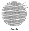
この実施形態では、金型100は、18.0mmの直径を有する送り穴プレート130、直径15.5mmの押出し物形成チャンバ150、直径0.8mmの送りチャンネル131、及び直径1mmのピン140を組み込む。各ピン140の間の距離は2mmであり、金型100はピン140の3つの環列を含み、六角形の格子構造を形成する合計36本のピンが得られる。本発明の利点は、金型設計が容易にスケール変更可能であり、例えば、36mm直径の直径を有する送り穴プレート130は、ピンの殆ど7つの環列(即ち、162本のピン)が可能であり、それにより、各々が1mm直径の162個の穴を有し、且つ2mmの穴間又はピン間の間隔を有する30mmの予成形品が製造されることになる(例えば、図5a及び5b参照)。
In this embodiment, the
当然のことであるが、他の規則的又は非規則的な格子構造が、送り穴プレート130に対するピン140及び送りチャンネル131の適切な配置によって形成されうる。さらには、切欠き部分に対応する長手通路が被押出し部材の中に必要とされる場合には、さしずめ、例えば、被押出し部材の内部分を露出するために、切欠き断面の形状に対応する適切な断面輪郭の通路形成部材又は通路形成部材の組合せが、送り穴プレート130の縁部に向かって配置されうる。
Of course, other regular or irregular grid structures may be formed by appropriate placement of
金型100を使用して重合体予成形品を押し出すことによって製造するために、30mmの断面直径のビレットが、165℃のチャンバ温度及び0.1mm/分の固定ラム速度で導入される。このチャンバ温度及びラム速度でビレットを金型100に通して押し出すために必要な力は、6MPaの領域内でビレットに対して得られる圧力に対応する約4.5kNである。金型100を使用して予成形品をケイ酸鉛ガラスから製造するために、0.1mm/分の固定ラム速度に関連する必要なビレットチャンバ温度は520℃である。したがって、必要とされる力は、35MPaのビレットに対する圧力に対応する約25kNである。
For manufacturing by extruding a polymer preform using the
本明細書で説明される複雑な横手構造を有する予成形品を形成する方法は、この点に関して従来技術では、かなりの手作業の投入及び高度に専門化された背景知識を必要とする繊細で難しい過程であったものを自動化する押出し機械に容易に適合されうる。一般的に、本押出し機械は、材料のビレットを受け入れるための受入れ口と、材料のビレットを加熱して押出し可能な材料を形成する加熱手段とを組み込む。次に、押出し可能な材料は、当業で知られている強制手段によって、必要に応じて金型の迅速な交換を可能にする金型受入れチャンバの中に配置される金型に押し通される。最後に、被押出し部材は次いで、それが回収前に冷却されうる出力チャンバの中に収容される。明白なことであるが、これは従来技術に優る大幅な進歩を表すものであり、このような押出し機械の最も重要な利点は、コンピュータ制御による厳密な速度及び力制御である。 The method of forming a preform with a complex transverse structure described herein is a delicate technique that requires considerable manual effort and highly specialized background knowledge in this regard. It can be easily adapted to an extrusion machine that automates what was a difficult process. Generally, the extrusion machine incorporates a receiving port for receiving a billet of material and heating means for heating the billet of material to form an extrudable material. The extrudable material is then forced through a mold located in a mold receiving chamber that allows for rapid replacement of the mold as needed by forcing means known in the art. The Finally, the extruded member is then housed in an output chamber where it can be cooled before recovery. Obviously, this represents a significant advance over the prior art, and the most important advantage of such an extrusion machine is precise speed and force control by computer control.
ここで図4a及び4bを参照すると、図2及び3に例示された3環列ピン送り穴プレート130の端面図と送り穴プレート130から押し出されたその対応するファイバ予成形品230の端面図とが示されている。ファイバ予成形品230は、外部領域232と、予成形品230を貫通する幾つかの長手チャンネル又は通路231から成る中間領域とを含み、これらの通路は、上で説明された送り穴プレート130の中に配置された対応するピン140によって形成され、それによってコア領域233を画定する。
4a and 4b, an end view of the three ring pin
同様に図5a及び5bでは、本発明の第3の実施形態に係る7環列ピン送り穴プレート170と、その対応するファイバ予成形品270との対応図が示されている。これは、必要に応じて金型設計をスケール変更し、よってその対応するファイバ予成形品をスケール変更できることを明白に証明する。この場合も、長手チャンネル又は通路271が外部領域272の内部に形成され、それは、同じようにコア領域273をファイバ予成形品270の中に画定する送り穴プレート170中のピン172の位置に対応する。送りチャンネル171の分布は、押し出された材料が、ピン172の周囲を均一に流れて通路271を形成する。この場合では、先の実施形態における3環列とは異なり、7環列が使用されている。
Similarly, in FIGS. 5a and 5b, there is shown a corresponding view of a seven-ring pin
図6a及び6bは、本発明の第4の実施形態に係る4環列送り穴プレート180及びファイバ予成形品280の同じような図を示す。この実施形態では、送りチャンネルが、3及び7環列設計のそれぞれの送りチャンネル131、171と比較して、2つの異なるサイズである。この様態では、押し出された材料は、より小さい直径の送りチャンネル181aと比較されるとき、より容易に大きい直径の送りチャンネル181bを通って流れることになる。この用途では、流量のこのような違いが、ピン182によって形成されたファイバ予成形品280中の長手チャンネル281の変形及び変位を低減するように機能したが、これは、得られる引き抜かれたファイバに対する潜在的な用途に応じた重要な配慮でありうる。
6a and 6b show similar views of a four-ring
ここで図7a及び7bを参照すると、本発明の第5の実施形態に係る多コア送りプレート190及び対応するファイバ予成形品290のそれぞれの端面図が示されている。この実施形態では、5つの外部コア領域294、295、296、297、298及び1つの内部コア領域293が、ピン192の配置に直接対応する長手チャンネル291の配置によって画定され、これらのピン自体は送り穴プレート190上の対応するコア領域193、194、195、196、197、198を画定した。この場合も、押出し過程によって導入された変形を補償するために押し出された材料の流量を変更するように、異なるサイズの送りチャンネル191a、191bが使用された。当業者によって理解されるように、ここに図示された予成形品の設計範囲は、本発明が広範に異なる複雑な横手幾何学形状を有する被押出し部材を提供するように適合されうる本発明の利用を明白に証明する。
Referring now to FIGS. 7a and 7b, there are shown end views of a
ここで図8を参照すると、外壁810と、4つの等間隔壁820、821、822、823によって支持された中心長手部分830とを有するファイバ予成形品800の端面図が示されている。この幾何学形状は、本出願の出願人に譲り受けられた2005年10月12日出願の豪州特許仮出願第2005905619号の優先権を主張する、"Fabrication of Nanowires"と題され、その内容の全体が参照により本明細書に組み込まれる同時係属出願に詳細に説明されているナノワイヤの形成に用途を有する。
Referring now to FIG. 8, an end view of a
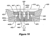
ここで図9及び10を参照すると、本発明の第6の実施形態に係る、図8に例示されたファイバ予成形品800を押し出すための金型400の後方及び側方断面図が示されている。この第6の例示的な実施形態では、必要とされる横手構造が、送りプレート430の中に配置された送りチャンネル435、436、437、438に通して材料を押し出すことによって送り出される、4本のピン440の各々の間の間隔445に対応する4つの等間隔の壁、支柱、又はウェブ部材820、821、822、823によって支持された、送りチャンネル431に対応する中心長手部分830の形成を伴う。金型100と同様に、金型400は、溝付き又はテーパ付き壁421を有するカラー420と、カラー420の壁の中に形成された肩部424に当接し、それによって金型入口チャンバ410と押出し物形成チャンバ450との間に障壁部材を形成する濾し又は送り穴プレート430とを具備する。
Referring now to FIGS. 9 and 10, there is shown a rear and side cross-sectional view of a
各ピン440は、内部テーパ付き部分442d、両側テーパ付き部分442c、内部テーパ付き部分442dと両側テーパ付き部分442cとの間に延びる両側中間テーパ付き部分442e、及び外部テーパ付き部分442aを含む。テーパ付き部分442a、442b、442c、442d、442eは、ピン440のほぼ中途まで下方に延び、押出し物形成チャンバ450の中へ押出し方向に延びる垂直壁部分442bの中で終わる。テーパ付き部分442a、442b、442c、442d、442e及び平行壁部分442bは、組み合わさって通路形成部材460としての役目を果たす。
Each
テーパ付き部分442a、442b、442c、442d、442eは、送りチャンネル431からの材料押出しによって形成された中心長手部分830を支持する壁、支柱、又はウェブ部分820、821、822、823を形成するために、送りチャンネル435、436、437、438からの材料押出しを案内するように機能する。カラー420の押出し物チャンバ壁423は、箱形又は正方形構成で配置され、それによって予成形品800の外壁810の正方形輪郭を形成する。各ピン440は、頂部平坦部分447からピン440の中へ延びる対応するねじ山付き開口446の中へねじ込まれる、位置決め穴434の中に配置された頂部ねじ441によって送りプレートに取り付けられる。
金型400の寸法の点では、送りプレート430が30mmの長さ及び幅を有し、押出し物形成チャンバ450が26mmの長さ及び幅を有する。ピン440の配置及びサイズによって、予成形品中に、2mmのコア径及び1.5mmの外壁厚さを有する、それぞれ約16mmの長さ及び0.5mmの厚さの壁、支柱、又はウェブ部分が得られる。
In terms of the dimensions of the
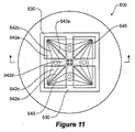
ここで図11及び12を参照すると、本発明の第6の例示的な実施形態に係る、図8に例示されたファイバ予成形品を押し出すための金型500の後方及び側方断面図が再び示されている。この第6の例示的な実施形態では、ピン540の幾何学形状が、ピン540毎に垂直壁部分542bに対してテーパ付き部分542a、542b、542c、542d、542eの程度及び範囲を変えることによって、押し出された材料がピン540の周囲をさらに容易に流れるように変更されている。さらには、ピン540は、このピン540の下方凹所543の中に配置されて、送り穴プレート530上に位置するねじ山付き受入れ開口534の中へ上向きにねじ込まれるねじ541によって、送り穴プレート530に着脱自在に取り付けられる。当業者によって理解されるように、本発明は、以前には従来技術の技法を使用して形成できなかった新規のファイバ予成形品設計を形成する能力を提供する。
Referring now to FIGS. 11 and 12, there is again a rear and side cross-sectional view of a
本発明では光ファイバ用の予成形品を製造することに関連して説明されているが、本発明は、本明細書に説明された原理に適合する他の用途を有することが理解されよう。 Although the present invention has been described in connection with manufacturing preforms for optical fibers, it will be understood that the present invention has other applications that are consistent with the principles described herein.
以上に説明された実施形態を少し検討すれば、本発明が、数多くの横手特徴構造を内部に有する光ファイバ予成形品を製造するための極めて簡素で、経済的な方法及び装置を提供し、それによって軟質ガラスの光子バンドギャップ及び大モード面積ファイバへの増大する関心によって動機付けられた、この種の光ファイバに対する増大する需要を満たすことが判明されよう。 Considering briefly the embodiments described above, the present invention provides a very simple and economical method and apparatus for manufacturing optical fiber preforms having a number of transverse feature structures therein, It will prove to meet the increasing demand for this type of optical fiber, thereby motivated by the increasing interest in soft glass photonic band gaps and large mode area fibers.
本発明の様々な態様に従って押し出される予成形品から生産されたナノワイヤ及びファイバは、限定するものではないが、科学的、医学的、軍事的/防衛的、及び商業的用途で使用するためのセンサ;コンピュータ、個人用携帯型情報端末(PDA、Personal Digital Assistant)、携帯電話のような電子製品用の表示器;カメラ及びカメラ電話用の画像表示器及びセンサ;光データ格納;光通信;光データ処理;交通信号灯;エングレービング;並びにレーザ用途を含めて、数多くの用途を有する。 Nanowires and fibers produced from preforms extruded in accordance with various aspects of the present invention include, but are not limited to, sensors for use in scientific, medical, military / defense, and commercial applications Computers, personal digital assistants (PDAs), displays for electronic products such as mobile phones; image displays and sensors for cameras and camera phones; optical data storage; optical communications; optical data It has a number of applications including processing; traffic lights; engraving; as well as laser applications.
本明細書で使用された「備える、含む(comprise)」という用語及びその派生語(例えば、comprises、comprising)はいずれも、それが言及する特徴構造を包含しているものと解釈されるべきであり、別途に言明又は示唆されない限り任意の追加的な特徴構造の存在を排除しようとするものではないことが理解されよう。 Any use of the terms “comprise” and its derivatives (eg, rises, comprising) as used herein should be construed as including the feature structure to which it refers. It will be understood that it is not intended to exclude the presence of any additional features unless otherwise stated or suggested.
本発明の装置及び方法の幾つかの実施形態が、以上の詳細な説明で説明されてきたが、本発明は、開示された実施形態に限定されるものではなく、以下の特許請求の範囲によって記載及び画定された本発明の範囲から逸脱することなく、数多くの再配置、変更、及び代用が可能であることが理解されよう。 While several embodiments of the apparatus and method of the present invention have been described in the foregoing detailed description, the present invention is not limited to the disclosed embodiments and is limited by the following claims. It will be appreciated that numerous rearrangements, modifications, and substitutions are possible without departing from the scope of the invention as described and defined.
Claims (17)
ビレットの形態の前記押出し可能な材料を受け入れるための入口チャンバと、
前記被押出し部材が形成される、終端が開口した押出し物形成チャンバと、
前記入口チャンバと前記終端が開口した押出し物形成チャンバとの間に押出し方向に配置された障壁部材であって、前記入口チャンバから前記終端が開口した押出し物形成チャンバへと前記障壁部材を貫通する各々独立した、間隔の空いた複数の送りチャンネルを備える障壁部材と、
前記障壁部材から実質的に押出し方向に、前記終端が開口した押出し物形成チャンバへと延びる通路形成部材と、を備え、前記送りチャンネルは、前記押出し可能な材料が前記間隔の空いた送りチャンネルから出ると実質的に前記通路形成部材の周囲を流れることを可能にするように前記通路形成部材に対して配置されて、対応する通路が前記被押出し部材の中に形成される、金型。 A mold for extruding extrudable material to form an extruded member,
An inlet chamber for receiving the extrudable material in the form of a billet;
An extrudate forming chamber having an open end in which the extruded member is formed;
A barrier member disposed in an extruding direction between the inlet chamber and the extrudate forming chamber open at the end, the barrier member penetrating from the inlet chamber to the extrudate forming chamber open at the end A barrier member comprising a plurality of independently spaced feed channels;
Substantially the extrusion direction from the barrier member, and a passage forming member extending into the extrusion-forming chamber in which the end is open, the feed channel, the feed channel before Symbol extrudable material is vacant the gap It is arranged relative to the passage forming member so as to allow flow around the substantially the passage forming member when exiting from the corresponding passage Ru is formed in the object to be extruded member, the die.
独立して障壁部材を貫通し、且つ前記障壁部材から押出し方向に、終端が開口した押出し物形成チャンバへと延びる通路形成部材の周囲に配置された、間隔の空いた複数の送りチャンネルに、入口チャンバの中に受け入れられたビレットの形態の押出し可能な材料を押し通すステップであって、前記障壁部材が、前記入口チャンバと前記終端が開口した押出し物形成チャンバとの間に配置されているステップと、
前記押出し可能な材料が前記間隔の空いた送りチャンネルから出ると、前記通路形成部材の周囲を流れることを可能にすることによって、通路を前記被押出し部材の中に形成するステップと、
を含む方法。 A method of extruding extrudable material to form an extruded member comprising:
A barrier member through Independently, and the extrusion direction from the barrier member, the termination is disposed around the passage forming member extending into the extrusion-forming chamber having an opening, a plurality of feed channels spaced inlet Pushing the extrudable material in the form of a billet received into the chamber , wherein the barrier member is disposed between the inlet chamber and the extrudate forming chamber open at the end ; ,
Forming a passage in the extruded member by allowing the extrudable material to flow around the passage forming member as it exits the spaced feed channels ;
Including methods.
前記押出し可能な材料を形成するために入口チャンバ中の材料のビレットを所定の温度に加熱するステップと、
前記押出し可能な材料を前記入口チャンバから障壁部材に通して終端が開口した押出し物形成チャンバの中へ押し入れるステップと、を含み、前記障壁部材は、前記入口チャンバと前記終端が開口した押出し物形成チャンバとの間に配置され、かつ、独立して前記障壁部材を貫通する間隔の空いた複数の送りチャンネルを有する送り穴プレートと、前記送り穴プレートから押出し方向に、前記終端が開口した押出し物形成チャンバへと延びる少なくとも1つの通路形成部材とを備え、前記押出し可能な材料が、前記間隔の空いた送りチャンネルから出ると、実質的に前記通路形成部材の周囲を流れさせられ、それにより少なくとも1つの対応する通路を前記被押出し部材の中に形成する方法。 A method of extruding extrudable material to form an extruded member comprising:
And heating the billet material in the inlet chamber to a predetermined temperature to form the extrudable material,
Pushing the extrudable material from the inlet chamber through a barrier member into an extrudate forming chamber having an open end , wherein the barrier member has an extrudate having the inlet chamber and the end open. A feed hole plate disposed between the forming chamber and having a plurality of spaced apart feed channels penetrating the barrier member independently; and an extrusion having the end opened in the push direction from the feed hole plate and at least one passage forming member Ru extends into objects forming chamber, wherein the extrudable material, upon exiting the vacant feeding channel of said interval, is to flow around substantially the passage forming member, it how to form at least one corresponding passage in the object to be extruded member by.
前記金型の、ビレットの形態の押出し可能な材料を受け入れるための入口チャンバと終端が開口した押出し物形成チャンバとの間に配置された障壁部材に、少なくとも1つの着脱自在に取付け可能な通路形成部材を取り付けるステップを含み、前記障壁部材は、間隔の空いた複数の送りチャンネルをさらに備え、前記間隔の空いた複数の送りチャンネルが、前記障壁部材を各々独立して貫通し、使用に際して前記押出し可能な材料が前記障壁部材を通って流れて前記間隔の空いた送りチャンネルから出ると、前記少なくとも1つの着脱自在に取付け可能な通路形成部材の周囲を流れさせられ、前記少なくとも1つの着脱自在に取付け可能な通路形成部材の位置が前記被押出し部材の中に形成された通路に対応する、方法。 A method of constructing a mold for extruding extrudable material to form an extruded member,
Forming at least one releasably attachable passageway in a barrier member of the mold between an inlet chamber for receiving an extrudable material in the form of a billet and an extrudate forming chamber having an open end. wherein the step of attaching a member, the barrier member further comprises a plurality of feed channels spaced plurality of feed channels empty the interval, penetrate the barrier member each independently, the in use extruding As possible material flows through the barrier member and out of the spaced feed channel, it is caused to flow around the at least one removably attachable passage-forming member and the at least one removably A method wherein the position of the attachable passage forming member corresponds to a passage formed in the extruded member.
材料のビレットを受け入れる受入れ部と、
押出し可能な材料を形成するために前記材料のビレットを加熱する加熱手段と、
請求項1〜9のいずれかに記載の金型を受け入れる金型受入れチャンバと、
被押出し部材を形成するために前記押出し可能な材料を前記金型に押し通す強制手段と、
前記被押出し部材を受け入れる出力チャンバと、
を備える押出し機械。 An extrusion machine,
A receiving part for receiving a billet of material;
Heating means for heating a billet of said material to form an extrudable material;
A mold receiving chamber for receiving the mold according to claim 1;
A forcing means for pushing the extrudable material through the mold to form an extruded member;
An output chamber for receiving the extruded member;
Extrusion machine equipped with.
Applications Claiming Priority (5)
| Application Number | Priority Date | Filing Date | Title |
|---|---|---|---|
| AU2005905619 | 2005-10-12 | ||
| AU2005905619A AU2005905619A0 (en) | 2005-10-12 | Fabrication of nanowires | |
| AU2005905620 | 2005-10-12 | ||
| AU2005905620A AU2005905620A0 (en) | 2005-10-12 | Method and device for forming microstructured fibre | |
| PCT/AU2006/001500 WO2007041791A1 (en) | 2005-10-12 | 2006-10-12 | Method and device for forming micro structured fibre |
Publications (2)
| Publication Number | Publication Date |
|---|---|
| JP2009511961A JP2009511961A (en) | 2009-03-19 |
| JP5242401B2 true JP5242401B2 (en) | 2013-07-24 |
Family
ID=44343937
Family Applications (1)
| Application Number | Title | Priority Date | Filing Date |
|---|---|---|---|
| JP2008534818A Active JP5242401B2 (en) | 2005-10-12 | 2006-10-12 | Method and apparatus for forming microstructured fibers |
Country Status (6)
| Country | Link |
|---|---|
| US (3) | US20090220785A1 (en) |
| EP (1) | EP1945583B1 (en) |
| JP (1) | JP5242401B2 (en) |
| AU (1) | AU2006301935B2 (en) |
| PL (1) | PL1945583T3 (en) |
| WO (1) | WO2007041791A1 (en) |
Families Citing this family (11)
| Publication number | Priority date | Publication date | Assignee | Title |
|---|---|---|---|---|
| GB0618942D0 (en) * | 2006-09-26 | 2006-11-08 | Brightwater Engineering Ltd | Apparatus and method |
| AU2008280830B2 (en) | 2007-07-24 | 2014-02-20 | Adelaide Research & Innovation Pty Ltd | Optical fiber sensor |
| US8647098B2 (en) * | 2010-09-22 | 2014-02-11 | Stratasys, Inc. | Liquefier assembly for use in extrusion-based additive manufacturing systems |
| US8571371B2 (en) * | 2011-06-15 | 2013-10-29 | The United States Of America As Represented By The Secretary Of The Navy | Direct extrusion method for the fabrication of photonic band gap (PBG) fibers and fiber preforms |
| US9488775B2 (en) * | 2012-05-03 | 2016-11-08 | University Of Central Florida Research Foundation, Inc. | Systems and methods for producing robust chalcogenide optical fibers |
| US9227353B2 (en) * | 2012-11-08 | 2016-01-05 | Solar Hydronics Corporation | Molding apparatus and method for operating same |
| JP6578007B2 (en) | 2015-01-14 | 2019-09-18 | ザ ユニバーシティ オブ アデライデThe University Of Adelaide | Temperature sensor |
| US10370280B2 (en) * | 2016-10-03 | 2019-08-06 | The United States Of America, As Represented By The Secretary Of The Navy | Method of making optical fibers with multiple openings |
| CN107088388B (en) * | 2017-04-06 | 2020-08-28 | 中国科学技术大学 | Composite aerogel material, preparation method and multifunctional recycling method thereof, multifunctional composite aerogel material and application |
| US11163109B2 (en) * | 2017-07-13 | 2021-11-02 | Nanyang Technological University | Fiber preform, optical fiber, methods for forming the same, and optical devices having the optical fiber |
| EP4032680A1 (en) * | 2021-01-21 | 2022-07-27 | SAB Sondermaschinen- und Anlagen-Bau GmbH | Method for producing an extrusion tool |
Family Cites Families (17)
| Publication number | Priority date | Publication date | Assignee | Title |
|---|---|---|---|---|
| US4025262A (en) * | 1974-11-18 | 1977-05-24 | General Electric Company | Variable length extrusion die |
| JPH01224112A (en) * | 1988-02-29 | 1989-09-07 | Showa Alum Corp | Die for extrusion |
| JPH0293602A (en) * | 1988-09-30 | 1990-04-04 | Matsushita Electric Ind Co Ltd | Production of optical fiber for infrared ray |
| JPH0422601A (en) * | 1990-05-18 | 1992-01-27 | Kobe Steel Ltd | Formed object with through hole and manufacture and device thereof |
| JP2987707B2 (en) * | 1990-07-11 | 1999-12-06 | 三菱レイヨン株式会社 | Plastic multifilament optical fiber |
| JPH0651141A (en) * | 1992-07-31 | 1994-02-25 | Mitsubishi Rayon Co Ltd | Production of multifilament type optical fiber made of plastic and optical fiber for endoscope formed by using the same |
| EP0945479B1 (en) * | 1998-02-23 | 2011-04-06 | Draka Comteq B.V. | Composite structural components containing thermotropic liquid crystalline polymer reinforcements for optical fiber cables |
| DE69928076T2 (en) * | 1999-03-23 | 2006-07-13 | Gaimont Universal Ltd. B.V.I. | Extruded, multi-tubular device |
| US20020154873A1 (en) * | 2001-01-26 | 2002-10-24 | Fiber-Line, Inc. | Core enclosures and methods for making the same |
| AUPR518201A0 (en) * | 2001-05-22 | 2001-06-14 | Redfern Photonics Pty Limited | Method of optical fibre preform manufacture |
| AU2002306061A1 (en) * | 2001-06-13 | 2002-12-23 | Samsung Electronics Co., Ltd. | Method for fabricating optical fiber preform using extrusion die |
| JP2003181527A (en) * | 2001-12-18 | 2003-07-02 | Kobe Steel Ltd | Extruding die, extruding equipment, extruded body and method for designing extruding die |
| GB2386434A (en) * | 2002-03-13 | 2003-09-17 | Univ Southampton | Microstructured optical fibre fabricated by extrusion through special extruder die |
| DE602004003342T2 (en) * | 2003-02-10 | 2007-06-14 | Nanoptics Inc., Gainesville | METHOD AND APPARATUS FOR THE MANUFACTURE OF OPTICAL TRANSMISSION MEDIA |
| JP4426210B2 (en) * | 2003-05-20 | 2010-03-03 | 日本碍子株式会社 | Molding jig and method for producing molded body using the same |
| US6993230B2 (en) * | 2003-08-01 | 2006-01-31 | The United States Of America As Represented By The Secretary Of The Navy | Hollow core photonic band gap infrared fibers |
| US20050056952A1 (en) * | 2003-09-15 | 2005-03-17 | Walker James K. | Method of manufacturing multi-polymer optical fiber cable |
-
2006
- 2006-10-12 EP EP06790370.8A patent/EP1945583B1/en not_active Not-in-force
- 2006-10-12 US US12/090,011 patent/US20090220785A1/en not_active Abandoned
- 2006-10-12 PL PL06790370T patent/PL1945583T3/en unknown
- 2006-10-12 AU AU2006301935A patent/AU2006301935B2/en active Active
- 2006-10-12 JP JP2008534818A patent/JP5242401B2/en active Active
- 2006-10-12 WO PCT/AU2006/001500 patent/WO2007041791A1/en active Application Filing
-
2017
- 2017-01-31 US US15/420,982 patent/US20170136657A1/en not_active Abandoned
-
2019
- 2019-05-28 US US16/424,110 patent/US20190275704A1/en not_active Abandoned
Also Published As
| Publication number | Publication date |
|---|---|
| US20170136657A1 (en) | 2017-05-18 |
| WO2007041791A1 (en) | 2007-04-19 |
| EP1945583B1 (en) | 2018-09-19 |
| US20190275704A1 (en) | 2019-09-12 |
| AU2006301935B2 (en) | 2012-11-29 |
| AU2006301935A1 (en) | 2007-04-19 |
| EP1945583A1 (en) | 2008-07-23 |
| PL1945583T3 (en) | 2019-01-31 |
| US20090220785A1 (en) | 2009-09-03 |
| EP1945583A4 (en) | 2012-05-02 |
| JP2009511961A (en) | 2009-03-19 |
Similar Documents
| Publication | Publication Date | Title |
|---|---|---|
| JP5242401B2 (en) | Method and apparatus for forming microstructured fibers | |
| US8449283B2 (en) | Dies for forming extrusions with thick and thin walls | |
| US8433167B2 (en) | Fused array preform fabrication of holey optical fibers | |
| CN102548736B (en) | Ribbon liquefier for use in extrusion-based digital manufacturing systems | |
| EP1119523B1 (en) | Method of fabricating photonic structures | |
| WO2005017569A3 (en) | Hollow core photonic band gap infrared fibers | |
| US10822262B2 (en) | Optical fibers with multiple openings from additive manufacturing | |
| DE19908936C2 (en) | Injection molding device and method for producing precision optical and precision mechanical parts from a thermoplastic | |
| JP2004527007A (en) | Optical fiber preform manufacturing method | |
| WO2004046777A1 (en) | Microstructured polymer signal guiding element | |
| US7186110B2 (en) | Apparatus of making wedged plates | |
| JP5598488B2 (en) | Manufacturing method of fluoride image guide | |
| WO2018067445A2 (en) | Method to make optical fibers with multiple openings | |
| CN211683392U (en) | Integrally-formed extrusion die for producing side-emitting optical fibers | |
| DE10252764B3 (en) | Production of a fiber optic hollow blank, used in the production of optical fibers for information systems, comprises preparing tube/rod units and joining to form a packet and heating | |
| TW200305497A (en) | Optical fiber production system and crosshead die therefor | |
| Ebendorff-Heidepriem et al. | Progress in the fabrication of soft glass microstructured optical fibres with complex and new structures | |
| CN212826714U (en) | Production equipment of side-emitting optical fiber with controllable light-emitting position | |
| CN110948824A (en) | Integrally-formed extrusion die for producing side-emitting optical fibers | |
| JP5497539B2 (en) | Plastic optical fiber manufacturing apparatus and plastic optical fiber manufacturing method | |
| IT201600105155A1 (en) | "EXTRUSION HEAD FOR A 3D PRINTING MACHINE" | |
| EP2390078A1 (en) | Device for producing a multilayer optical waveguide | |
| DE102010004262A1 (en) | Laser arrangement, has light conductor comprising core and shell, and pump fiber comprising end that runs longitudinal to shell, where cross-section is increased in tapered manner over one of elongated areas of light conductor | |
| DE202009010448U1 (en) | Device for coupling light into a light guide, laser arrangement with such a device and preform for producing the device |
Legal Events
| Date | Code | Title | Description |
|---|---|---|---|
| A072 | Dismissal of procedure [no reply to invitation to correct request for examination] |
Free format text: JAPANESE INTERMEDIATE CODE: A072 Effective date: 20090115 |
|
| A621 | Written request for application examination |
Free format text: JAPANESE INTERMEDIATE CODE: A621 Effective date: 20091002 |
|
| A977 | Report on retrieval |
Free format text: JAPANESE INTERMEDIATE CODE: A971007 Effective date: 20120208 |
|
| A131 | Notification of reasons for refusal |
Free format text: JAPANESE INTERMEDIATE CODE: A131 Effective date: 20120213 |
|
| A601 | Written request for extension of time |
Free format text: JAPANESE INTERMEDIATE CODE: A601 Effective date: 20120508 |
|
| A602 | Written permission of extension of time |
Free format text: JAPANESE INTERMEDIATE CODE: A602 Effective date: 20120515 |
|
| A521 | Request for written amendment filed |
Free format text: JAPANESE INTERMEDIATE CODE: A523 Effective date: 20120606 |
|
| TRDD | Decision of grant or rejection written | ||
| A01 | Written decision to grant a patent or to grant a registration (utility model) |
Free format text: JAPANESE INTERMEDIATE CODE: A01 Effective date: 20130314 |
|
| A61 | First payment of annual fees (during grant procedure) |
Free format text: JAPANESE INTERMEDIATE CODE: A61 Effective date: 20130403 |
|
| FPAY | Renewal fee payment (event date is renewal date of database) |
Free format text: PAYMENT UNTIL: 20160412 Year of fee payment: 3 |
|
| R150 | Certificate of patent or registration of utility model |
Free format text: JAPANESE INTERMEDIATE CODE: R150 |
|
| R250 | Receipt of annual fees |
Free format text: JAPANESE INTERMEDIATE CODE: R250 |
|
| R250 | Receipt of annual fees |
Free format text: JAPANESE INTERMEDIATE CODE: R250 |
|
| R250 | Receipt of annual fees |
Free format text: JAPANESE INTERMEDIATE CODE: R250 |
|
| R250 | Receipt of annual fees |
Free format text: JAPANESE INTERMEDIATE CODE: R250 |