JP5224238B2 - elevator - Google Patents
elevator Download PDFInfo
- Publication number
- JP5224238B2 JP5224238B2 JP2007315081A JP2007315081A JP5224238B2 JP 5224238 B2 JP5224238 B2 JP 5224238B2 JP 2007315081 A JP2007315081 A JP 2007315081A JP 2007315081 A JP2007315081 A JP 2007315081A JP 5224238 B2 JP5224238 B2 JP 5224238B2
- Authority
- JP
- Japan
- Prior art keywords
- machine
- hoisting machine
- elevator
- support
- hoisting
- Prior art date
- Legal status (The legal status is an assumption and is not a legal conclusion. Google has not performed a legal analysis and makes no representation as to the accuracy of the status listed.)
- Expired - Fee Related
Links
- 230000003014 reinforcing effect Effects 0.000 claims description 14
- 239000000463 material Substances 0.000 claims description 3
- 238000000034 method Methods 0.000 description 3
- 229910000831 Steel Inorganic materials 0.000 description 1
- 230000001174 ascending effect Effects 0.000 description 1
- 230000003028 elevating effect Effects 0.000 description 1
- 238000012423 maintenance Methods 0.000 description 1
- 238000004519 manufacturing process Methods 0.000 description 1
- 238000012986 modification Methods 0.000 description 1
- 230000004048 modification Effects 0.000 description 1
- 230000002787 reinforcement Effects 0.000 description 1
- 239000010959 steel Substances 0.000 description 1
Images




Landscapes
- Lift-Guide Devices, And Elevator Ropes And Cables (AREA)
- Cage And Drive Apparatuses For Elevators (AREA)
Description
本発明は、昇降路の頂部に機械室を持たないエレベータに関する。 The present invention relates to an elevator having no machine room at the top of a hoistway.
例えば、機械室を持たないエレベータとして、以下のものが開示されている。このエレベータは、昇降路内を昇降する乗りかごと、昇降路内に配置された巻上機と、乗りかごの上部に支持されたかご側シーブと、巻上機に巻きかけられるとともに、一端でかご側シーブを介して乗りかごを吊り下げる巻き上げロープと、巻き上げロープの他端で吊り下げられるつり合い重りと、を備えている。 For example, the following is disclosed as an elevator without a machine room. The elevator is wound around the hoisting machine, the hoisting machine disposed in the hoistway, the car sheave supported on the upper part of the car, and the hoisting machine. A hoisting rope for suspending the car via the car-side sheave and a counterweight suspended at the other end of the hoisting rope are provided.
このエレベータでは、乗りかごの上部にかご側シーブが配置されているため、昇降路底部のピット深さが低減されている。また、乗りかごの上部に作業者が乗ることで、巻上機やかご側シーブのメンテナンスを集中的に行うことができるようになっている。
ところで、マシンルームレスのエレベータにおいて、巻上機等を配置させるための昇降路頂部の空間、すなわちオーバヘッド部分の大きさを省スペース化したいという要望がある。しかしながら、上記従来のエレベータでは、オーバヘッド部分の大きさを小さくするための配慮がなく、改良の余地があった。 By the way, in a machine roomless elevator, there is a demand for saving space in the space at the top of a hoistway for arranging a hoisting machine or the like, that is, the size of an overhead portion. However, the conventional elevator has no room for improvement because there is no consideration for reducing the size of the overhead portion.
本発明の目的は、昇降路のオーバヘッド部分の高さ寸法を小さくすることができるとともに、巻上機を簡単に取り外せるエレベータを提供することにある。 An object of the present invention is to provide an elevator capable of reducing the height dimension of the overhead portion of the hoistway and easily removing the hoisting machine .
前記目的を達成するために、本発明の一つの形態に係るエレベータは、昇降路内を昇降する乗りかごと、前記乗りかごの昇降を駆動することが可能な巻上機と、前記巻上機を支持する支持構造と、を具備し、前記支持構造は、前記巻上機を直接支持するマシンビームと、前記マシンビームと直交する方向に延びるとともに、前記マシンビームを支持する支持梁と、前記昇降路の上部に枠状に形成されるとともに、前記支持梁を支持するやぐらと、前記支持梁と前記やぐらとの間に介在される防振材と、を有し、前記巻上機は、前記支持構造の高さの範囲内で逆さ向きに固定され、前記巻上機は、前記マシンビームに引っ掛けるための小板状の引っ掛け部を具備し、前記マシンビームは、前記引っ掛け部を受ける受け部と、前記受け部に隣接して設けられるとともに、前記引っ掛け部の前記巻上機の回転軸方向における幅寸法よりも大きく形成された切欠部と、を具備する。 In order to achieve the above object, an elevator according to one embodiment of the present invention includes a car that moves up and down in a hoistway, a hoisting machine that can drive the raising and lowering of the car, and the hoisting machine A support beam that supports the hoisting machine, a support beam that extends in a direction orthogonal to the machine beam and supports the machine beam, and It is formed in a frame shape at the upper part of the hoistway, and has a tower that supports the support beam, and a vibration isolating material interposed between the support beam and the tower, the hoisting machine is The hoisting machine is fixed in an inverted direction within the range of the height of the support structure, and the hoisting machine has a small plate-like hooking part for hooking the machine beam, and the machine beam receives the hooking part. Adjacent to the receiving part Together provided, comprising a, a larger formed notch than the width in the rotation axis direction of the hoisting machine of the hook portion.
この場合、前記マシンビームは、前記巻上機を間に挟んだ両側に配置される一対のもので構成されるとよい。このとき、一対の前記マシンビーム間に渡された補強梁をさらに具備することが好ましい。この補強梁は、巻上機の駆動シーブの近傍に配置されると、さらに有効である。 In this case, the machine beam may be composed of a pair of beams arranged on both sides of the hoisting machine. At this time, it is preferable to further comprise a reinforcing beam passed between the pair of machine beams. This reinforcing beam is more effective when it is arranged near the drive sheave of the hoisting machine.
本発明に係るエレベータによれば、昇降路のオーバヘッド部分の高さ寸法を小さくすることが可能であるとともに、巻上機を簡単に取り外すことが可能なエレベータを提供できる。 According to the elevator according to the present invention, it is possible to provide an elevator that can reduce the height dimension of the overhead portion of the hoistway and can easily remove the hoisting machine .
以下、図1と図2を参照して、エレベータの第1の参考例について説明する。以下に述べる各参考例及び一実施の形態では、いわゆるマシンルームレスのエレベータに適用した場合を例に説明する。 Hereinafter, a first reference example of an elevator will be described with reference to FIGS. 1 and 2. In each reference example and one embodiment described below, a case where the present invention is applied to a so-called machine roomless elevator will be described as an example.
図1に示すように、エレベータ11は、例えば、昇降路12と、昇降路12内を昇降できる乗りかご13と、一端の近傍で乗りかご13が吊り下げられるメインロープ14と、メインロープ14の中ほどが巻きかけられる巻上機15と、昇降路12の上部に設けられるとともに巻上機15を支持する支持構造16と、メインロープ14の他端の近傍に吊り下げられるつり合い重り17と、乗りかご13の昇降をガイドするメインレールと、つり合い重り17の昇降をガイドするカウンターレールと、を備えている。
As shown in FIG. 1, the
エレベータ11は、メインロープ14の一端が固定される第1のロープヒッチ21と、メインロープ14の他端が固定される第2のロープヒッチ22と、を備えている。第1のロープヒッチ21は、支持構造16の後述するヒッチビーム23に固定されている。第2のロープヒッチ22は、支持構造16の後述するマシンビーム24に固定されている。エレベータ11は、さらに、乗りかご13の昇降速度を調整するためのガバナなどを備えているが、ガバナの図示を省略している。
The
昇降路12は、支持構造16の後述する建屋梁25が固定される壁部12Aを有している。メインロープ14は、複数本のもので構成されている。メインロープ14は、例えば、シングルラップ方式で巻上機15に巻きかけられている。乗りかご13は、例えば、かご本体26と、かご本体26の上側に配置された一対のかご上シーブ27と、を有している。一対のかご上シーブ27は、乗りかご13の対角方向に沿って斜めに取り付けられている。もっとも、乗りかご13のシーブは、かご上シーブ27に限定されるものではなく、乗りかご13の下側に取り付けられていてもよい。
The
巻上機15は、駆動装置本体31と、駆動装置本体31に取り付けられた駆動シーブ32と、を有している。巻上機15は、乗りかご13の昇降を駆動することができる。つり合い重り17は、つり合い重り本体33と、つり合い重り本体33の上側に配置された一対のつり合い重りシーブ34と、を有している。
The hoisting
支持構造16は、巻上機15を直接支持するマシンビーム24と、マシンビーム24を支持する支持梁35と、支持梁35を支持するやぐら36と、支持梁35とやぐら36との間に介在される防振材37と、第1のロープヒッチ21を支持するヒッチビーム23と、を有する。防振材37は、例えば、ゴム状の弾性体で構成されている。
The
図1に示すように、支持梁35は、マシンビーム24と直交する方向に延びている。やぐら36は、昇降路12の上部に枠状に形成されている。やぐらは、昇降路12の壁部12Aに固定される一対の建屋梁25と、一対の建屋梁25に渡された一対の受け梁38と、を有している。
As shown in FIG. 1, the
図2に示すように、マシンビーム24は、一対のもので構成されており、巻上機15を間に挟んだ両側に配置されている。マシンビーム24は、ビーム本体41と、ビーム本体41の側部に形成された「L」字形の支持部42と、支持部42の上側に固定された取付台43と、を備えている。支持部42は、ビーム本体41の側面からリブ状に突出するように複数個所に形成されている。取付台43の上面に巻上機15の脚部15Aが載置される。この状態において、巻上機15の脚部15Aは、取付台43に対して複数のボルトで固定される。
As shown in FIG. 2, the
巻上機15は、マシンビーム24と一部重複する高さに配置されている。このため、マシンビーム24の上側に巻上機15を載置した場合に比して、昇降路12頂部の空間、すなわちオーバヘッド部分の大きさが小さくなっている。
The hoisting
以上が、エレベータ11の第1の参考例である。本参考例によれば、エレベータ11は、昇降路12内を昇降する乗りかご13と、乗りかご13の昇降を駆動することが可能な巻上機15と、巻上機15を支持する支持構造16と、を具備し、支持構造16は、巻上機15を直接支持するマシンビーム24と、マシンビーム24と直交する方向に延びるとともに、マシンビーム24を支持する支持梁35と、昇降路12の上部に枠状に形成されるとともに、支持梁35を支持するやぐら36と、支持梁35とやぐら36との間に介在される防振材37と、を有し、巻上機15は、マシンビーム24と一部重複する高さに配置される。
The above is the first reference example of the
この構成によれば、巻上機15が上方に突出することが防止されるため、昇降路12のオーバヘッド部分の寸法を小さくすることができる。また、支持梁35とやぐら36との間に防振材37が介在されるため、巻上機15において発生する振動を防振材37によって吸収することができる。
According to this configuration, the hoisting
続いて、図3を参照して、エレベータの第2の参考例について説明する。第2の参考例のエレベータ51は、巻上機15の設置向きが第1の参考例と異なっているが、他の部分は共通している。このため、主として第1の参考例と異なる部分について説明し、第1の参考例と共通する箇所については共通の符号を付して説明を省略する。
Next, a second reference example of the elevator will be described with reference to FIG.
図3に示すように、第2の参考例の巻上機15は、逆さ向きでマシンビーム24に固定されている。すなわち、巻上機15の脚部は、第1の参考例のものよりも幅広に形成されて引っ掛け部15Bを構成している。引っ掛け部15Bは、マシンビーム24の取付台43に引っかかって固定されている。第2の参考例では、巻上機15は、マシンビーム24、支持梁35、およびやぐら36の高さの範囲内に配置されている。すなわち、巻上機15は、支持構造16の高さの範囲内に配置されている。
As shown in FIG. 3, the hoisting
第2の参考例によれば、巻上機15は、支持構造16の高さの範囲内に配置される。この構成によれば、マシンビーム24の上方に巻上機15が突出してしまうことがない。これにより、オーバヘッド部分の寸法をより一層低減することができ、省スペース化を図ることができる。
According to the second reference example , the hoisting
この場合、巻上機は、逆さ向きで固定される。この構成によれば、巻上機15を支持構造16の高さの範囲内とすることを簡単に実現することができる。
In this case, the hoisting machine is fixed upside down. According to this configuration, the hoisting
続いて、図4と図5を参照して、エレベータの第3の参考例について説明する。第3の参考例のエレベータ61は、支持構造63の構成が第1の参考例と異なっているが、他の部分は共通している。このため、主として第1の参考例と異なる部分について説明し、第1の参考例と共通する箇所については共通の符号を付して説明を省略する。
Subsequently, a third reference example of the elevator will be described with reference to FIGS. 4 and 5.
図4に示すように、支持構造63は、巻上機15を直接支持する一対のマシンビーム24と、一対のマシンビーム24間に渡された補強梁62と、マシンビーム24を支持する支持梁35と、支持梁35を支持するやぐら36と、支持梁35とやぐら36との間に介在される防振材37と、第1のロープヒッチ21を支持するヒッチビーム23と、を有する。
As shown in FIG. 4, the
やぐら36は、昇降路12の上部に枠状に形成されている。やぐら36は、昇降路12の壁部12Aに固定される一対の建屋梁25と、一対の建屋梁25に渡された一対の受け梁38と、を有している。
The
図4と図5に示すように、補強梁62は、長方形の板状に形成されている。補強梁62は、マシンビーム24のビーム本体41の上面に固定されている。補強梁62は、巻上機15の駆動シーブ32の近傍に配置されている。
As shown in FIGS. 4 and 5, the reinforcing
以上が、エレベータの第3の参考例である。第3の参考例によれば、エレベータ61は、一対のマシンビーム24間に渡された補強梁62をさらに具備する。この構成によれば、マシンビーム24にかかる巻上機15の荷重を補強梁62にも分散させることができる。これによって、マシンビーム24に負荷が掛かった際に、マシンビーム24が倒れてしまうことを防止することができる。
The above is the third reference example of the elevator. According to the third reference example , the
この場合、補強梁62は、巻上機15の駆動シーブ32の近傍に配置される。この構成によれば、駆動シーブ32にかかる吊り下げ荷重を補強梁62に効率よく分散させることができる。このため、マシンビーム24にかかる荷重を補強梁62に分散させることができる。これによって、マシンビーム24の型格を下げて、省スペース化および製造コストの削減を図ることもできる。
In this case, the reinforcing
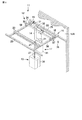
続いて、図6と図7を参照して、エレベータの一実施の形態について説明する。一実施の形態のエレベータ71は、支持構造72の構成が第2の参考例と異なっているが、他の部分は共通している。このため、主として第2の参考例と異なる部分について説明し、第2の参考例と共通する箇所については共通の符号を付して説明を省略する。
Then, with reference to FIG. 6 and FIG. 7, one Embodiment of an elevator is described. The
支持構造72は、巻上機15を直接支持する一対のマシンビーム24と、一対のマシンビーム24間に渡された補強梁62と、マシンビーム24を支持する支持梁35と、支持梁35を支持するやぐら36と、支持梁35とやぐら36との間に介在される防振材37と、第1のロープヒッチ21を支持するヒッチビーム23と、を有する。マシンビーム24は、巻上機15を間に挟んだ両側に配置されている。
The
やぐら36は、昇降路12の上部に枠状に形成されている。やぐら36は、昇降路12の壁部12Aに固定される一対の建屋梁25と、一対の建屋梁25に渡された一対の受け梁38と、を有している。
The
マシンビーム24は、ビーム本体41と、ビーム本体41の側部に形成された「L」字形の支持部42と、支持部42の上側に固定された受け部である取付台43と、を備えている。支持部42は、ビーム本体41の側面からリブ状に突出するように複数個所に形成されている。また、本実施形態では、受け部である取付台43に隣接して、切欠部73を設けている。切欠部73は、その幅寸法が巻上機の後述する引っ掛け部15Bの幅寸法よりも大きく形成されている。
The
巻上機15は、例えば、図3に示すものと同様に、逆さ向きでマシンビーム24に固定される。巻上機15は、小板上の引っ掛け部15Bを有している。取付台43の上面にこの引っ掛け部15Bが載置される。この状態で、取付台43と引っ掛け部15Bは、複数のボルトで固定されている。
The hoisting
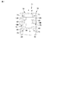
続いて図6と図7を参照して、巻上機15の取り外し作業について説明する。まず、巻上機15の引っ掛け部15Bと、マシンビーム24の取付台43との間のボルト締めを解除する。そして、巻上機15をその回転軸A方向にスライド移動させて、図6に示す状態から図7に示す状態にすることで、引っ掛け部15Bと取付台43との当接を解除する。図7に示す状態において、切欠部73を介して引っ掛け部15Bを下方に通すことで、巻上機15を取り外すことができる。
Next, with reference to FIG. 6 and FIG. 7, the removal work of the hoisting
一実施の形態によれば、巻上機15は、マシンビーム24に引っ掛けるための小板状の引っ掛け部15Bを具備し、マシンビーム24は、引っ掛け部15Bを受ける受け部である取付台43と、取付台43に隣接して設けられるとともに、引っ掛け部15Bの幅寸法よりも大きく形成された切欠部73と、を具備する。
According to one embodiment , the hoisting
この構成によれば、巻上機15を回転軸A方向にスライド移動させて、引っ掛け部15Bを切欠部73内に落とし込むことで、巻上機15を下方に取り外すことができる。これにより、巻上機15を回転軸A方向に少ない距離だけ移動させることで、簡単に巻上機15を取り外すことができる。
According to this configuration, the hoisting
続いて、図8と図9を参照して、エレベータの第4の参考例について説明する。第4の参考例のエレベータ81は、支持構造82の構成が第1の参考例と異なっているが、他の部分は共通している。このため、主として第1の参考例と異なる部分について説明し、第1の参考例と共通する箇所については共通の符号を付して説明を省略する。
Subsequently, a fourth reference example of the elevator will be described with reference to FIGS. 8 and 9. The
図8に示すように、支持構造82は、巻上機15を直接支持する一対のマシンビーム24と、マシンビーム24を支持する支持梁35と、支持梁35を支持するやぐら36と、支持梁35とやぐら36との間に介在される防振材37と、第1のロープヒッチ21を支持するヒッチビーム23と、を有する。また、支持構造82は、マシンビーム24と支持梁35の間の位置に、溝部を有するレール83と、溝部内にはまり込むように配置された円柱状のローラ84と、を有している。第4の参考例では、レール83およびローラ84によって、マシンビーム24は、巻上機15の回転軸A方向と直交する方向である幅方向Wにスライド移動することができる。なお、支持構造82は、マシンビーム24が意図しないときにスライド移動してしまうことを防止するため、図示しない安全装置を備えている。
As shown in FIG. 8, the
やぐら36は、昇降路12の上部に枠状に形成されている。やぐら36は、昇降路12の壁部12Aに固定される一対の建屋梁25と、一対の建屋梁25に渡された一対の受け梁38と、を有している。
The
図8と図9を参照して、巻上機15の取り外し作業について説明する。まず、巻上機15の脚部15Aと、マシンビーム24の取付台43との間のボルト締めを解除する。そして、図9に示すようにマシンビーム24を幅方向Wにスライド移動させる。これによって、巻上機15の脚部15Aとマシンビーム24の取付台43との間の当接を解除することができる。こうして、巻上機15を下方に取り外すことができる。
The removal operation of the hoisting
第4の参考例によれば、一対のマシンビーム24は、巻上機15の回転軸A方向と直交する幅方向Wにスライド移動できる。この構成によれば、巻上機15を移動させることなく、巻上機15を取り外すことができる。特に、乗りかご13のサイズ、昇降路12のサイズが小さいなどの理由で巻上機をその回転軸A方向に移動させることができない場合などに第4の参考例のエレベータは有効である。
According to the fourth reference example , the pair of machine beams 24 can slide in the width direction W perpendicular to the direction of the rotation axis A of the hoisting
本発明は、前記実施の形態に限定されるものではない。このほか、発明の要旨を逸脱しない範囲で種々変形実施可能であるのは勿論である。 The present invention is not limited to the embodiment described above. Of course, various modifications can be made without departing from the scope of the invention.
71…エレベータ、12…昇降路、13…乗りかご、15…巻上機、15B…引っ掛け部、72…支持構造、24…マシンビーム、32…駆動シーブ、35…支持梁、36…やぐら、37…防振材、43…取付台(受け部)、62…補強梁、73…切欠部、A…回転軸 71: Elevator, 12: Hoistway, 13: Car, 15: Hoisting machine, 15B: Hook, 72 ... Support structure, 24 ... Machine beam, 32 ... Drive sheave, 35 ... Support beam, 36 ... Tower, 37 ... Vibration-proof material, 43 ... Mounting base (receiving part), 62 ... Reinforcement beam, 73 ... Notch, A ... Rotating shaft
Claims (4)
前記乗りかごの昇降を駆動することが可能な巻上機と、
前記巻上機を支持する支持構造と、
を具備し、
前記支持構造は、
前記巻上機を直接支持するマシンビームと、
前記マシンビームと直交する方向に延びるとともに、前記マシンビームを支持する支持梁と、
前記昇降路の上部に枠状に形成されるとともに、前記支持梁を支持するやぐらと、
前記支持梁と前記やぐらとの間に介在される防振材と、
を有し、
前記巻上機は、前記支持構造の高さの範囲内で逆さ向きに固定され、
前記巻上機は、前記マシンビームに引っ掛けるための小板状の引っ掛け部を具備し、
前記マシンビームは、前記引っ掛け部を受ける受け部と、前記受け部に隣接して設けられるとともに、前記引っ掛け部の前記巻上機の回転軸方向における幅寸法よりも大きく形成された切欠部と、を具備することを特徴とするエレベータ。 A car that goes up and down in the hoistway,
A hoisting machine capable of driving the raising and lowering of the car;
A support structure for supporting the hoisting machine;
Comprising
The support structure is
A machine beam directly supporting the hoisting machine;
A support beam that extends in a direction orthogonal to the machine beam and supports the machine beam;
A tower that is formed in a frame shape at the top of the hoistway and supports the support beam,
Anti-vibration material interposed between the support beam and the tower;
Have
The hoisting machine is fixed upside down within the height of the support structure,
The hoisting machine comprises a small plate-like hook for hooking on the machine beam,
The machine beam includes a receiving portion that receives the hook portion, a notch portion that is provided adjacent to the receiving portion, and that is formed to be larger than a width dimension of the hook portion in the rotation axis direction of the hoisting machine, The elevator characterized by comprising .
Priority Applications (2)
| Application Number | Priority Date | Filing Date | Title |
|---|---|---|---|
| JP2007315081A JP5224238B2 (en) | 2007-12-05 | 2007-12-05 | elevator |
| CN 200810169165 CN101450763B (en) | 2007-12-05 | 2008-11-04 | Elevator |
Applications Claiming Priority (1)
| Application Number | Priority Date | Filing Date | Title |
|---|---|---|---|
| JP2007315081A JP5224238B2 (en) | 2007-12-05 | 2007-12-05 | elevator |
Publications (2)
| Publication Number | Publication Date |
|---|---|
| JP2009137695A JP2009137695A (en) | 2009-06-25 |
| JP5224238B2 true JP5224238B2 (en) | 2013-07-03 |
Family
ID=40733276
Family Applications (1)
| Application Number | Title | Priority Date | Filing Date |
|---|---|---|---|
| JP2007315081A Expired - Fee Related JP5224238B2 (en) | 2007-12-05 | 2007-12-05 | elevator |
Country Status (2)
| Country | Link |
|---|---|
| JP (1) | JP5224238B2 (en) |
| CN (1) | CN101450763B (en) |
Families Citing this family (9)
| Publication number | Priority date | Publication date | Assignee | Title |
|---|---|---|---|---|
| CN102862898A (en) * | 2012-09-29 | 2013-01-09 | 苏州新里程电控系统有限公司 | Elevator framework |
| CN102862894A (en) * | 2012-09-29 | 2013-01-09 | 苏州新里程电控系统有限公司 | Elevator rack |
| CN103723603A (en) * | 2013-12-20 | 2014-04-16 | 康力电梯股份有限公司 | Traction driving device of household lift |
| JP6218158B2 (en) * | 2014-07-03 | 2017-10-25 | 三菱電機株式会社 | Machine room-less elevator |
| JP6113239B2 (en) * | 2015-09-04 | 2017-04-12 | 三菱電機ビルテクノサービス株式会社 | Elevator hoisting machine motor replacement device and elevator hoisting machine motor replacement method |
| CN107098247A (en) * | 2017-04-27 | 2017-08-29 | 苏州菱奥电梯有限公司 | Traction-type villa elevator |
| CN108069319B (en) * | 2017-12-27 | 2023-06-13 | 苏州江南嘉捷电梯有限公司 | A mounting structure for a driving device |
| CN110065872A (en) * | 2019-05-12 | 2019-07-30 | 江苏西德电梯有限公司 | A kind of fixed device of traction machine of elevator without engine room |
| CN110884985B (en) * | 2019-12-03 | 2021-07-09 | 辛格林电梯(中国)有限公司 | A heavy duty freight elevator |
Family Cites Families (6)
| Publication number | Priority date | Publication date | Assignee | Title |
|---|---|---|---|---|
| JPH05319745A (en) * | 1992-05-19 | 1993-12-03 | Hitachi Ltd | Elevator hoist support device |
| FI98210C (en) * | 1993-06-28 | 1997-05-12 | Kone Oy | Arrangement for unification of elevator machinery with building |
| JPH0769569A (en) * | 1993-09-07 | 1995-03-14 | Toshiba Corp | Elevator |
| JP4108454B2 (en) * | 2002-11-21 | 2008-06-25 | 三菱電機ビルテクノサービス株式会社 | Elevator equipment |
| JP2005067787A (en) * | 2003-08-22 | 2005-03-17 | Toshiba Elevator Co Ltd | Aligning adjustment mechanism of elevator winch |
| JP2007204238A (en) * | 2006-02-03 | 2007-08-16 | Toshiba Elevator Co Ltd | Elevator having rope brake |
-
2007
- 2007-12-05 JP JP2007315081A patent/JP5224238B2/en not_active Expired - Fee Related
-
2008
- 2008-11-04 CN CN 200810169165 patent/CN101450763B/en not_active Expired - Fee Related
Also Published As
| Publication number | Publication date |
|---|---|
| CN101450763B (en) | 2013-03-13 |
| JP2009137695A (en) | 2009-06-25 |
| CN101450763A (en) | 2009-06-10 |
Similar Documents
| Publication | Publication Date | Title |
|---|---|---|
| JP2009137695A (en) | Elevator | |
| EP2844600B1 (en) | Method of installing a machine in an elevator system | |
| EP1302430B1 (en) | Elevator device | |
| JP2007099515A (en) | Method for mounting support means of lift cage to lift cage and lift shaft | |
| JP2010208822A (en) | Elevator car | |
| JP4376585B2 (en) | Machine room-less elevator device | |
| JP5278360B2 (en) | Renewal method of hydraulic elevator and rope type elevator renewed by the method | |
| JP5329031B2 (en) | Elevator equipment | |
| JP5278359B2 (en) | Renewal method of hydraulic elevator and rope type elevator renewed by the method | |
| JP2011168406A (en) | Elevator device | |
| JP2007210703A (en) | Device and method for installing hoist machine in machine-room-less elevator | |
| JP2009062177A (en) | elevator | |
| JP4974374B2 (en) | Installation method of elevator suspension rod vibration isolator | |
| JP2012201497A (en) | Machine bed and lifting device | |
| JP5608960B2 (en) | Machine room-less elevator device | |
| JP4368656B2 (en) | Elevator main rope support device | |
| JP2008230809A (en) | Main rope hitch device for elevator | |
| JP4770241B2 (en) | Elevator equipment | |
| JP3765809B2 (en) | Elevator equipment | |
| JP4342252B2 (en) | elevator | |
| JP2005067813A (en) | Lifting device and lifting method for winch of elevator | |
| JP2005231770A5 (en) | ||
| KR200236339Y1 (en) | Rotary lift crane | |
| JP5681284B2 (en) | elevator | |
| KR100804886B1 (en) | Elevator device |
Legal Events
| Date | Code | Title | Description |
|---|---|---|---|
| A621 | Written request for application examination |
Free format text: JAPANESE INTERMEDIATE CODE: A621 Effective date: 20100317 |
|
| A977 | Report on retrieval |
Free format text: JAPANESE INTERMEDIATE CODE: A971007 Effective date: 20120510 |
|
| A131 | Notification of reasons for refusal |
Free format text: JAPANESE INTERMEDIATE CODE: A131 Effective date: 20120515 |
|
| RD04 | Notification of resignation of power of attorney |
Free format text: JAPANESE INTERMEDIATE CODE: A7424 Effective date: 20120529 |
|
| A521 | Written amendment |
Free format text: JAPANESE INTERMEDIATE CODE: A523 Effective date: 20120629 |
|
| TRDD | Decision of grant or rejection written | ||
| A01 | Written decision to grant a patent or to grant a registration (utility model) |
Free format text: JAPANESE INTERMEDIATE CODE: A01 Effective date: 20130212 |
|
| A61 | First payment of annual fees (during grant procedure) |
Free format text: JAPANESE INTERMEDIATE CODE: A61 Effective date: 20130304 |
|
| R150 | Certificate of patent or registration of utility model |
Free format text: JAPANESE INTERMEDIATE CODE: R150 |
|
| FPAY | Renewal fee payment (event date is renewal date of database) |
Free format text: PAYMENT UNTIL: 20160322 Year of fee payment: 3 |
|
| S531 | Written request for registration of change of domicile |
Free format text: JAPANESE INTERMEDIATE CODE: R313531 |
|
| R350 | Written notification of registration of transfer |
Free format text: JAPANESE INTERMEDIATE CODE: R350 |
|
| LAPS | Cancellation because of no payment of annual fees |