JP5220182B2 - 絶縁劣化検出装置 - Google Patents
絶縁劣化検出装置 Download PDFInfo
- Publication number
- JP5220182B2 JP5220182B2 JP2011502699A JP2011502699A JP5220182B2 JP 5220182 B2 JP5220182 B2 JP 5220182B2 JP 2011502699 A JP2011502699 A JP 2011502699A JP 2011502699 A JP2011502699 A JP 2011502699A JP 5220182 B2 JP5220182 B2 JP 5220182B2
- Authority
- JP
- Japan
- Prior art keywords
- phase
- zero
- current
- phase current
- insulation deterioration
- Prior art date
- Legal status (The legal status is an assumption and is not a legal conclusion. Google has not performed a legal analysis and makes no representation as to the accuracy of the status listed.)
- Active
Links
- 238000009413 insulation Methods 0.000 title claims description 114
- 230000006866 deterioration Effects 0.000 title claims description 78
- 238000001514 detection method Methods 0.000 claims description 49
- 238000005259 measurement Methods 0.000 claims description 10
- 238000007689 inspection Methods 0.000 claims description 4
- 238000000034 method Methods 0.000 description 14
- 238000010586 diagram Methods 0.000 description 13
- 238000012545 processing Methods 0.000 description 11
- 230000001360 synchronised effect Effects 0.000 description 10
- 230000015556 catabolic process Effects 0.000 description 7
- 238000006731 degradation reaction Methods 0.000 description 7
- 238000012937 correction Methods 0.000 description 6
- 230000006870 function Effects 0.000 description 6
- 230000008569 process Effects 0.000 description 4
- 230000008859 change Effects 0.000 description 3
- 238000004891 communication Methods 0.000 description 3
- 238000003745 diagnosis Methods 0.000 description 3
- 238000012935 Averaging Methods 0.000 description 2
- 206010014357 Electric shock Diseases 0.000 description 2
- 230000002159 abnormal effect Effects 0.000 description 2
- 239000004020 conductor Substances 0.000 description 2
- 230000006698 induction Effects 0.000 description 2
- 230000007774 longterm Effects 0.000 description 2
- 239000000463 material Substances 0.000 description 2
- 238000000137 annealing Methods 0.000 description 1
- 238000006243 chemical reaction Methods 0.000 description 1
- 239000011248 coating agent Substances 0.000 description 1
- 238000000576 coating method Methods 0.000 description 1
- 239000000470 constituent Substances 0.000 description 1
- 239000002173 cutting fluid Substances 0.000 description 1
- 239000010730 cutting oil Substances 0.000 description 1
- 230000000694 effects Effects 0.000 description 1
- 238000011156 evaluation Methods 0.000 description 1
- 239000000284 extract Substances 0.000 description 1
- 238000000605 extraction Methods 0.000 description 1
- 230000004907 flux Effects 0.000 description 1
- 238000010438 heat treatment Methods 0.000 description 1
- 239000011810 insulating material Substances 0.000 description 1
- 239000000696 magnetic material Substances 0.000 description 1
- 238000012423 maintenance Methods 0.000 description 1
- 239000000203 mixture Substances 0.000 description 1
- 238000012806 monitoring device Methods 0.000 description 1
- 238000012544 monitoring process Methods 0.000 description 1
- 229910000889 permalloy Inorganic materials 0.000 description 1
- 230000035945 sensitivity Effects 0.000 description 1
- 230000007704 transition Effects 0.000 description 1
- 230000001960 triggered effect Effects 0.000 description 1
- 230000000007 visual effect Effects 0.000 description 1
Images


Classifications
-
- G—PHYSICS
- G01—MEASURING; TESTING
- G01R—MEASURING ELECTRIC VARIABLES; MEASURING MAGNETIC VARIABLES
- G01R31/00—Arrangements for testing electric properties; Arrangements for locating electric faults; Arrangements for electrical testing characterised by what is being tested not provided for elsewhere
- G01R31/34—Testing dynamo-electric machines
- G01R31/343—Testing dynamo-electric machines in operation
-
- G—PHYSICS
- G01—MEASURING; TESTING
- G01R—MEASURING ELECTRIC VARIABLES; MEASURING MAGNETIC VARIABLES
- G01R27/00—Arrangements for measuring resistance, reactance, impedance, or electric characteristics derived therefrom
- G01R27/02—Measuring real or complex resistance, reactance, impedance, or other two-pole characteristics derived therefrom, e.g. time constant
- G01R27/16—Measuring impedance of element or network through which a current is passing from another source, e.g. cable, power line
-
- G—PHYSICS
- G01—MEASURING; TESTING
- G01R—MEASURING ELECTRIC VARIABLES; MEASURING MAGNETIC VARIABLES
- G01R31/00—Arrangements for testing electric properties; Arrangements for locating electric faults; Arrangements for electrical testing characterised by what is being tested not provided for elsewhere
- G01R31/12—Testing dielectric strength or breakdown voltage ; Testing or monitoring effectiveness or level of insulation, e.g. of a cable or of an apparatus, for example using partial discharge measurements; Electrostatic testing
- G01R31/1227—Testing dielectric strength or breakdown voltage ; Testing or monitoring effectiveness or level of insulation, e.g. of a cable or of an apparatus, for example using partial discharge measurements; Electrostatic testing of components, parts or materials
-
- G—PHYSICS
- G01—MEASURING; TESTING
- G01R—MEASURING ELECTRIC VARIABLES; MEASURING MAGNETIC VARIABLES
- G01R31/00—Arrangements for testing electric properties; Arrangements for locating electric faults; Arrangements for electrical testing characterised by what is being tested not provided for elsewhere
- G01R31/34—Testing dynamo-electric machines
Description
インバータ装置と電動機との間の給電電路に設けられ、給電電路の零相電流を計測する零相電流計測手段と、
電動機の回転を待機させるための指令制御手段と、
電動機がN相駆動される場合(Nは自然数)、少なくとも(N―1)相の相電流の値を計測する手段と、
各相の絶縁抵抗を演算する演算手段とを備え、
零相電流計測手段は、回転待機時に外力がかかってもシャフト軸が回転しないように各相に給電する相電流の総和を計測し、
演算手段は、電動機のシャフト軸の固定位置がN個以上異なる状態で計測した零相電流および各相の相電流の値から、各相の絶縁抵抗を演算する。
インバータ装置と電動機との間の給電電路に設けられ、給電電路の零相電流を計測する零相電流計測手段と、
電動機の回転を待機させるための指令制御手段とを備え、
零相電流計測手段は、回転待機時に外力がかかってもシャフト軸が回転しないように各相に給電する相電流の総和を計測し、
電動機に給電する電流成分において、絶縁劣化検出時のみ、トルクに無効な電流成分を増加させ、相電圧を増加させる。
図1は、本発明の実施の形態1に係る絶縁劣化検出装置101を示す構成図である。負荷機器3は、インバータ装置1から給電電路6a,6b,6cを経由して相電流を給電することにより駆動する。例えば、インバータ駆動される負荷機器には、電動機、無停電電源装置(UPS)、電磁調理器、そして照明等が挙げられる。制御装置2は、インバータ駆動の制御を行う機能を有し、負荷機器の駆動方式に応じて、三相の駆動電流の波形や大きさや周期等の制御信号をインバータ装置1に伝送する。
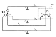
図4は、本発明の実施の形態2に係る絶縁劣化検出装置103を示す構成図である。ここでは、図1の負荷機器3として電動機10を用いた場合を説明する。
図5は、本発明の実施の形態3に係る絶縁劣化検出装置104を示す構成図である。絶縁劣化検出装置104は、図4に示した構成とほぼ同じであるものの、各相の相電流を計測する手段として、各相の相電流を計測する電流センサ5と、各相の絶縁抵抗値を演算する絶縁抵抗演算回路12とをさらに備える。また、実施の形態2では電動機10の給電電路6a,6b,6cから漏洩する電流の総和、すなわち零相電流に基づいて絶縁劣化を検出していたが、本実施形態では、電動機の給電電路6a,6b,6cの各相から漏洩する電流に基づいて各相の絶縁劣化を検出する。

図7は、本発明の実施の形態4に係る絶縁劣化検出装置105を示す構成図である。絶縁劣化検出装置105は、図1に示した構成とほぼ同じであるものの、絶縁劣化検出回路93が2つの信号の位相を一致させる位相補正回路13をさらに備える。
5 電流センサ、 6a,6b,6c 給電電路、 7 周波数演算回路、
8 同期検波回路、 9 表示器、 10 電動機、 11 ケーブル、
12 絶縁劣化診断装置、 13 位相補正回路、
21 電流センサの出力波形、 22 零相電流センサの出力波形、
90、91、92 絶縁劣化検出回路、
101、102、103、104、105 絶縁劣化検出装置。
Claims (5)
- インバータ駆動される電動機における絶縁劣化を検出する装置であって、
インバータ装置と電動機との間の給電電路に設けられ、給電電路の零相電流を計測する零相電流計測手段と、
電動機の回転を待機させるための指令制御手段と、
電動機がN相駆動される場合(Nは自然数)、少なくとも(N―1)相の相電流の値を計測する手段と、
各相の絶縁抵抗を演算する演算手段とを備え、
零相電流計測手段は、回転待機時に外力がかかってもシャフト軸が回転しないように各相に給電する相電流の総和を計測し、
演算手段は、電動機のシャフト軸の固定位置がN個以上異なる状態で計測した零相電流および各相の相電流の値から、各相の絶縁抵抗を演算することを特徴とする絶縁劣化検出装置。 - 電動機の稼動開始時および稼動終了時を除く通常稼動時において、絶縁劣化検出を実施することを特徴とする請求項1記載の絶縁劣化検出装置。
- 電動機の稼動開始時または稼動終了時に設定された検査モードにおいて、絶縁劣化検出を実施することを特徴とする請求項1記載の絶縁劣化検出装置。
- 電動機の稼動終了時を除く通常稼動時において、各相の絶縁抵抗を演算できなかった場合は、電動機の稼動終了時に設定された検査モードにおいて、各相の絶縁抵抗を演算するために不足分の計測を実施することを特徴とする請求項1記載の絶縁劣化検出装置。
- インバータ駆動される電動機における絶縁劣化を検出する装置であって、
インバータ装置と電動機との間の給電電路に設けられ、給電電路の零相電流を計測する零相電流計測手段と、
電動機の回転を待機させるための指令制御手段とを備え、
零相電流計測手段は、回転待機時に外力がかかってもシャフト軸が回転しないように各相に給電する相電流の総和を計測し、
電動機に給電する電流成分において、絶縁劣化検出時のみ、トルクに無効な電流成分を増加させ、相電圧を増加させることを特徴とする絶縁劣化検出装置。
Priority Applications (1)
| Application Number | Priority Date | Filing Date | Title |
|---|---|---|---|
| JP2011502699A JP5220182B2 (ja) | 2009-03-05 | 2010-02-08 | 絶縁劣化検出装置 |
Applications Claiming Priority (4)
| Application Number | Priority Date | Filing Date | Title |
|---|---|---|---|
| JP2009052005 | 2009-03-05 | ||
| JP2009052005 | 2009-03-05 | ||
| PCT/JP2010/051754 WO2010100998A1 (ja) | 2009-03-05 | 2010-02-08 | 絶縁劣化検出装置 |
| JP2011502699A JP5220182B2 (ja) | 2009-03-05 | 2010-02-08 | 絶縁劣化検出装置 |
Publications (2)
| Publication Number | Publication Date |
|---|---|
| JPWO2010100998A1 JPWO2010100998A1 (ja) | 2012-09-06 |
| JP5220182B2 true JP5220182B2 (ja) | 2013-06-26 |
Family
ID=42709560
Family Applications (1)
| Application Number | Title | Priority Date | Filing Date |
|---|---|---|---|
| JP2011502699A Active JP5220182B2 (ja) | 2009-03-05 | 2010-02-08 | 絶縁劣化検出装置 |
Country Status (7)
| Country | Link |
|---|---|
| US (1) | US9335380B2 (ja) |
| JP (1) | JP5220182B2 (ja) |
| KR (1) | KR101279193B1 (ja) |
| CN (1) | CN102317800B (ja) |
| DE (1) | DE112010000959B4 (ja) |
| TW (1) | TWI426282B (ja) |
| WO (1) | WO2010100998A1 (ja) |
Cited By (1)
| Publication number | Priority date | Publication date | Assignee | Title |
|---|---|---|---|---|
| JP2019174385A (ja) * | 2018-03-29 | 2019-10-10 | オムロン株式会社 | 絶縁計測装置及び絶縁計測方法 |
Families Citing this family (23)
| Publication number | Priority date | Publication date | Assignee | Title |
|---|---|---|---|---|
| JP5467063B2 (ja) * | 2011-01-24 | 2014-04-09 | 三菱電機株式会社 | 発電電動機の異常検出装置および異常検出方法 |
| JP5618910B2 (ja) * | 2011-06-01 | 2014-11-05 | 三菱電機株式会社 | 絶縁劣化監視システム |
| JP5705102B2 (ja) * | 2011-12-21 | 2015-04-22 | 三菱電機株式会社 | 絶縁劣化診断装置 |
| JP6134101B2 (ja) * | 2012-03-14 | 2017-05-24 | 東芝三菱電機産業システム株式会社 | 繰り返しインパルス電圧による部分放電計測システムおよび部分放電計測方法 |
| JP5631444B1 (ja) * | 2013-05-27 | 2014-11-26 | タナシン電機株式会社 | 漏洩電流算出装置及び漏洩電流算出方法 |
| US9476944B2 (en) * | 2013-06-12 | 2016-10-25 | GM Global Technology Operations LLC | Insulation inspection instrument |
| CN103823166B (zh) * | 2014-02-28 | 2016-07-20 | 武汉大学 | 一种固体绝缘劣化进程的疲劳测试装置及测试方法 |
| JP6306913B2 (ja) * | 2014-03-19 | 2018-04-04 | 株式会社小松製作所 | 車載用電力供給システムの漏電検出装置及び油圧ショベル |
| KR101803132B1 (ko) * | 2014-04-28 | 2017-11-29 | 엘에스산전 주식회사 | 무 변압기형 태양광 인버터의 누설전류 감시 장치 |
| JP6353694B2 (ja) * | 2014-05-13 | 2018-07-04 | 株式会社日立製作所 | 劣化診断システム |
| CN104065335B (zh) * | 2014-06-04 | 2016-06-29 | 北京京东方能源科技有限公司 | 光伏汇流装置 |
| CN105158649B (zh) * | 2015-06-03 | 2018-06-19 | 廖小雄 | 电机电器在线绝缘状态无线监控装置 |
| CN104931835B (zh) * | 2015-06-25 | 2017-12-12 | 桂林理工大学 | 含电磁作用力的绞线试样绝缘加速老化寿命实验方法 |
| JP6588261B2 (ja) * | 2015-07-10 | 2019-10-09 | 株式会社日立産機システム | 絶縁監視装置およびインバータ装置 |
| KR20180102542A (ko) * | 2016-01-08 | 2018-09-17 | 미쓰비시덴키 가부시키가이샤 | 절연 저항 측정 장치 |
| US10132846B2 (en) * | 2016-06-14 | 2018-11-20 | Analog Devices Global | Method of and apparatus for learning the phase error or timing delays within a current transducer and power measurement apparatus including current transducer error correction |
| WO2018042488A1 (ja) * | 2016-08-29 | 2018-03-08 | 株式会社日立製作所 | 回転機の診断装置および診断方法 |
| JP6897933B2 (ja) * | 2017-07-03 | 2021-07-07 | 株式会社三英社製作所 | 高圧絶縁監視装置及び高圧絶縁監視方法 |
| JP6818155B2 (ja) * | 2017-09-05 | 2021-01-20 | 株式会社日立製作所 | 交流電動機の監視装置および監視方法、ならびに電動機駆動システムの監視装置および監視方法 |
| JP2019161876A (ja) * | 2018-03-14 | 2019-09-19 | オークマ株式会社 | 電動機の絶縁劣化検出装置 |
| FR3079305B1 (fr) * | 2018-03-23 | 2020-05-01 | IFP Energies Nouvelles | Procede de determination d'au moins deux resistances equivalentes d'isolement d'un systeme electrique |
| CN110596547B (zh) * | 2019-09-19 | 2021-08-24 | 上海电力大学 | 逆变器驱动电机的匝绝缘状态在线监测方法 |
| CN116660702B (zh) * | 2023-07-31 | 2023-10-20 | 季华实验室 | 一种三相电机绝缘电阻检测方法及其相关设备 |
Citations (8)
| Publication number | Priority date | Publication date | Assignee | Title |
|---|---|---|---|---|
| JPS61155869A (ja) * | 1984-12-28 | 1986-07-15 | Toyo Commun Equip Co Ltd | 位相補償を施した絶縁抵抗測定方法 |
| JPH02254375A (ja) * | 1989-03-09 | 1990-10-15 | General Electric Co <Ge> | 電気装置内における地絡事故を検出しかつ制限するためのシステム |
| JPH08168166A (ja) * | 1994-10-11 | 1996-06-25 | Toshiba Corp | 地絡故障検出方法およびその装置 |
| JP2000028671A (ja) * | 1998-07-07 | 2000-01-28 | Toyo Commun Equip Co Ltd | 絶縁検出器 |
| JP2003270284A (ja) * | 2002-03-13 | 2003-09-25 | Mitsubishi Electric Building Techno Service Co Ltd | 電機機器のための巻線レアショート監視装置 |
| JP2005057965A (ja) * | 2003-08-07 | 2005-03-03 | Toyota Industries Corp | 電力変換装置 |
| JP2006164787A (ja) * | 2004-12-08 | 2006-06-22 | Fuji Electric Systems Co Ltd | 漏電遮断器動作原因分析装置 |
| JP2008157838A (ja) * | 2006-12-26 | 2008-07-10 | Hitachi Industrial Equipment Systems Co Ltd | 絶縁監視装置 |
Family Cites Families (24)
| Publication number | Priority date | Publication date | Assignee | Title |
|---|---|---|---|---|
| JPS6385380A (ja) | 1986-09-29 | 1988-04-15 | Toshiba Corp | 電動機の故障検出方法 |
| JPH0769401B2 (ja) | 1989-05-18 | 1995-07-31 | 三菱電機株式会社 | 誘導電動機の定数測定方法 |
| JPH07239359A (ja) | 1994-02-25 | 1995-09-12 | Mitsubishi Electric Corp | インバータ装置及びその運転方法 |
| US5691643A (en) | 1994-10-11 | 1997-11-25 | Kabushiki Kaisha Toshiba | Ground fault detecting apparatus and method for detecting ground fault of field circuit and exciting circuit by detecting ground fault current flowing from ground to neutral point of exciting circuit |
| JP3355905B2 (ja) | 1995-02-13 | 2002-12-09 | 三菱電機株式会社 | 絶縁監視システム |
| JP3441596B2 (ja) | 1995-04-28 | 2003-09-02 | 三菱電機株式会社 | 絶縁劣化診断装置 |
| US6320350B1 (en) * | 1995-09-21 | 2001-11-20 | Takashi Take | Modulation control type of AC machine |
| US6043664A (en) * | 1997-06-06 | 2000-03-28 | General Electric Company | Method and apparatus for turn fault detection in multi-phase AC motors |
| US6114859A (en) * | 1997-07-14 | 2000-09-05 | Nissin Electric Co., Ltd. | Harmonic characteristic measuring method and harmonic characteristic measuring apparatus |
| JP3721116B2 (ja) * | 2000-11-14 | 2005-11-30 | 株式会社豊田中央研究所 | 駆動装置,動力出力装置およびその制御方法 |
| JP2003274551A (ja) * | 2002-03-15 | 2003-09-26 | Fuji Heavy Ind Ltd | 絶縁状態監視システム |
| JP4378151B2 (ja) * | 2003-11-04 | 2009-12-02 | 株式会社デンソー | モータ駆動装置 |
| EP1720242A1 (en) * | 2003-11-26 | 2006-11-08 | Nsk Ltd., | Device for controlling motor-driven power steering device |
| WO2007017802A2 (en) * | 2005-08-09 | 2007-02-15 | Nxp B.V. | Driver for a brushless motor and data reading/writing device comprising a brushless motor controlled by such a driver |
| JP4855057B2 (ja) | 2005-12-06 | 2012-01-18 | ファナック株式会社 | モータ駆動装置 |
| JP4179346B2 (ja) * | 2006-06-16 | 2008-11-12 | トヨタ自動車株式会社 | 充電制御装置およびそれを備えた車両 |
| KR100817890B1 (ko) * | 2006-08-16 | 2008-03-31 | 김보경 | 전선로의 절연검출장치 및 절연검출방법 |
| JP2008102096A (ja) | 2006-10-20 | 2008-05-01 | Fanuc Ltd | モータの絶縁抵抗劣化検出装置 |
| US7514932B2 (en) * | 2007-01-04 | 2009-04-07 | Trane International Inc. | Method of recognizing signal mis-wiring of a three-phase circuit |
| JP2009025219A (ja) | 2007-07-23 | 2009-02-05 | Kazuhisa Yamashita | クランプ式活線絶縁測定法及び測定器 |
| CN101109779B (zh) * | 2007-08-06 | 2010-05-19 | 上海发电设备成套设计研究院 | 一种汽轮发电机绝缘热老化寿命预测方法及系统 |
| JP2009058234A (ja) | 2007-08-29 | 2009-03-19 | Sbc Co Ltd | 漏れ電流測定装置及び測定方法 |
| JP5270952B2 (ja) | 2008-04-17 | 2013-08-21 | オークマ株式会社 | モータ制御装置 |
| US8289033B2 (en) * | 2009-01-23 | 2012-10-16 | GM Global Technology Operations LLC | Systems and methods for detecting resonance on a direct current voltage bus |
-
2010
- 2010-02-08 CN CN201080007995.4A patent/CN102317800B/zh active Active
- 2010-02-08 US US13/254,696 patent/US9335380B2/en active Active
- 2010-02-08 KR KR1020117020490A patent/KR101279193B1/ko active IP Right Grant
- 2010-02-08 DE DE112010000959.7T patent/DE112010000959B4/de not_active Expired - Fee Related
- 2010-02-08 JP JP2011502699A patent/JP5220182B2/ja active Active
- 2010-02-08 WO PCT/JP2010/051754 patent/WO2010100998A1/ja active Application Filing
- 2010-03-04 TW TW099106249A patent/TWI426282B/zh active
Patent Citations (8)
| Publication number | Priority date | Publication date | Assignee | Title |
|---|---|---|---|---|
| JPS61155869A (ja) * | 1984-12-28 | 1986-07-15 | Toyo Commun Equip Co Ltd | 位相補償を施した絶縁抵抗測定方法 |
| JPH02254375A (ja) * | 1989-03-09 | 1990-10-15 | General Electric Co <Ge> | 電気装置内における地絡事故を検出しかつ制限するためのシステム |
| JPH08168166A (ja) * | 1994-10-11 | 1996-06-25 | Toshiba Corp | 地絡故障検出方法およびその装置 |
| JP2000028671A (ja) * | 1998-07-07 | 2000-01-28 | Toyo Commun Equip Co Ltd | 絶縁検出器 |
| JP2003270284A (ja) * | 2002-03-13 | 2003-09-25 | Mitsubishi Electric Building Techno Service Co Ltd | 電機機器のための巻線レアショート監視装置 |
| JP2005057965A (ja) * | 2003-08-07 | 2005-03-03 | Toyota Industries Corp | 電力変換装置 |
| JP2006164787A (ja) * | 2004-12-08 | 2006-06-22 | Fuji Electric Systems Co Ltd | 漏電遮断器動作原因分析装置 |
| JP2008157838A (ja) * | 2006-12-26 | 2008-07-10 | Hitachi Industrial Equipment Systems Co Ltd | 絶縁監視装置 |
Cited By (1)
| Publication number | Priority date | Publication date | Assignee | Title |
|---|---|---|---|---|
| JP2019174385A (ja) * | 2018-03-29 | 2019-10-10 | オムロン株式会社 | 絶縁計測装置及び絶縁計測方法 |
Also Published As
| Publication number | Publication date |
|---|---|
| US20110320146A1 (en) | 2011-12-29 |
| KR20110111529A (ko) | 2011-10-11 |
| KR101279193B1 (ko) | 2013-06-26 |
| JPWO2010100998A1 (ja) | 2012-09-06 |
| CN102317800B (zh) | 2014-07-30 |
| WO2010100998A1 (ja) | 2010-09-10 |
| TW201037333A (en) | 2010-10-16 |
| TWI426282B (zh) | 2014-02-11 |
| DE112010000959T5 (de) | 2012-08-09 |
| CN102317800A (zh) | 2012-01-11 |
| US9335380B2 (en) | 2016-05-10 |
| DE112010000959B4 (de) | 2016-03-17 |
Similar Documents
| Publication | Publication Date | Title |
|---|---|---|
| JP5220182B2 (ja) | 絶縁劣化検出装置 | |
| TWI432747B (zh) | 絕緣劣化診斷裝置 | |
| CN103999309B (zh) | 用于电弧故障检测和中断的系统和结合方法 | |
| Ukil et al. | Detection of stator short circuit faults in three-phase induction motors using motor current zero crossing instants | |
| EP2366112B1 (en) | Method and apparatus for off-line testing of multi-phase alternating current machines | |
| EP2992339B1 (en) | System and method for detecting excess voltage drop in three-phase ac circuits | |
| JP5705102B2 (ja) | 絶縁劣化診断装置 | |
| JPH11160337A (ja) | 機械的に整流される直流電動機における回転速度を検出する方法 | |
| KR20130084775A (ko) | 유도 전동기의 회전자 결함 진단 장치, 방법 및 상기 방법을 실행시키기 위한 컴퓨터 판독 가능한 프로그램을 기록한 매체 | |
| CN101988951B (zh) | 电机的空隙调整方法 | |
| CN110546881A (zh) | 用于电气系统中的故障检测的负序电压的分段估计 | |
| CN105699896B (zh) | 一种适用于感应电机转子故障诊断方法 | |
| EP3745149B1 (en) | Power conversion device, rotating machine system using same, and diagnosis method for same | |
| JP6588261B2 (ja) | 絶縁監視装置およびインバータ装置 | |
| JP5369818B2 (ja) | インバータ装置の故障検出方法 | |
| JP2017123701A (ja) | モータの保全装置およびモータシステム | |
| RU2297704C1 (ru) | Способ защиты асинхронного двигателя от витковых замыканий | |
| RU2714532C1 (ru) | Дифференциальный способ обнаружения витковых замыканий в трехфазном трансформаторе | |
| KR200386320Y1 (ko) | 전기측정기 | |
| Stojcic et al. | Detecting incipient stator winding conductor faults in inverter fed machines | |
| JP3329672B2 (ja) | 誘導電動機定数測定装置 | |
| JP2003248023A (ja) | 電子式交流電流計 | |
| Bachir et al. | On-line stator faults diagnosis by parameter estimation | |
| KR20060101006A (ko) | 전기측정기 |
Legal Events
| Date | Code | Title | Description |
|---|---|---|---|
| A131 | Notification of reasons for refusal |
Free format text: JAPANESE INTERMEDIATE CODE: A131 Effective date: 20121113 |
|
| A521 | Request for written amendment filed |
Free format text: JAPANESE INTERMEDIATE CODE: A523 Effective date: 20130108 |
|
| TRDD | Decision of grant or rejection written | ||
| A01 | Written decision to grant a patent or to grant a registration (utility model) |
Free format text: JAPANESE INTERMEDIATE CODE: A01 Effective date: 20130205 |
|
| A61 | First payment of annual fees (during grant procedure) |
Free format text: JAPANESE INTERMEDIATE CODE: A61 Effective date: 20130305 |
|
| FPAY | Renewal fee payment (event date is renewal date of database) |
Free format text: PAYMENT UNTIL: 20160315 Year of fee payment: 3 |
|
| R150 | Certificate of patent or registration of utility model |
Ref document number: 5220182 Country of ref document: JP Free format text: JAPANESE INTERMEDIATE CODE: R150 |
|
| R250 | Receipt of annual fees |
Free format text: JAPANESE INTERMEDIATE CODE: R250 |
|
| R250 | Receipt of annual fees |
Free format text: JAPANESE INTERMEDIATE CODE: R250 |
|
| R250 | Receipt of annual fees |
Free format text: JAPANESE INTERMEDIATE CODE: R250 |
|
| R250 | Receipt of annual fees |
Free format text: JAPANESE INTERMEDIATE CODE: R250 |
|
| R250 | Receipt of annual fees |
Free format text: JAPANESE INTERMEDIATE CODE: R250 |
|
| R250 | Receipt of annual fees |
Free format text: JAPANESE INTERMEDIATE CODE: R250 |
|
| R250 | Receipt of annual fees |
Free format text: JAPANESE INTERMEDIATE CODE: R250 |
|
| R250 | Receipt of annual fees |
Free format text: JAPANESE INTERMEDIATE CODE: R250 |
|
| R250 | Receipt of annual fees |
Free format text: JAPANESE INTERMEDIATE CODE: R250 |