JP5220016B2 - Catheter with auxiliary balloon - Google Patents
Catheter with auxiliary balloon Download PDFInfo
- Publication number
- JP5220016B2 JP5220016B2 JP2009525559A JP2009525559A JP5220016B2 JP 5220016 B2 JP5220016 B2 JP 5220016B2 JP 2009525559 A JP2009525559 A JP 2009525559A JP 2009525559 A JP2009525559 A JP 2009525559A JP 5220016 B2 JP5220016 B2 JP 5220016B2
- Authority
- JP
- Japan
- Prior art keywords
- balloon
- catheter
- petal
- lumen
- auxiliary
- Prior art date
- Legal status (The legal status is an assumption and is not a legal conclusion. Google has not performed a legal analysis and makes no representation as to the accuracy of the status listed.)
- Expired - Fee Related
Links
Images


Classifications
-
- A—HUMAN NECESSITIES
- A61—MEDICAL OR VETERINARY SCIENCE; HYGIENE
- A61M—DEVICES FOR INTRODUCING MEDIA INTO, OR ONTO, THE BODY; DEVICES FOR TRANSDUCING BODY MEDIA OR FOR TAKING MEDIA FROM THE BODY; DEVICES FOR PRODUCING OR ENDING SLEEP OR STUPOR
- A61M25/00—Catheters; Hollow probes
- A61M25/10—Balloon catheters
- A61M25/1002—Balloon catheters characterised by balloon shape
-
- A—HUMAN NECESSITIES
- A61—MEDICAL OR VETERINARY SCIENCE; HYGIENE
- A61F—FILTERS IMPLANTABLE INTO BLOOD VESSELS; PROSTHESES; DEVICES PROVIDING PATENCY TO, OR PREVENTING COLLAPSING OF, TUBULAR STRUCTURES OF THE BODY, e.g. STENTS; ORTHOPAEDIC, NURSING OR CONTRACEPTIVE DEVICES; FOMENTATION; TREATMENT OR PROTECTION OF EYES OR EARS; BANDAGES, DRESSINGS OR ABSORBENT PADS; FIRST-AID KITS
- A61F2/00—Filters implantable into blood vessels; Prostheses, i.e. artificial substitutes or replacements for parts of the body; Appliances for connecting them with the body; Devices providing patency to, or preventing collapsing of, tubular structures of the body, e.g. stents
- A61F2/95—Instruments specially adapted for placement or removal of stents or stent-grafts
- A61F2/954—Instruments specially adapted for placement or removal of stents or stent-grafts for placing stents or stent-grafts in a bifurcation
-
- A—HUMAN NECESSITIES
- A61—MEDICAL OR VETERINARY SCIENCE; HYGIENE
- A61F—FILTERS IMPLANTABLE INTO BLOOD VESSELS; PROSTHESES; DEVICES PROVIDING PATENCY TO, OR PREVENTING COLLAPSING OF, TUBULAR STRUCTURES OF THE BODY, e.g. STENTS; ORTHOPAEDIC, NURSING OR CONTRACEPTIVE DEVICES; FOMENTATION; TREATMENT OR PROTECTION OF EYES OR EARS; BANDAGES, DRESSINGS OR ABSORBENT PADS; FIRST-AID KITS
- A61F2/00—Filters implantable into blood vessels; Prostheses, i.e. artificial substitutes or replacements for parts of the body; Appliances for connecting them with the body; Devices providing patency to, or preventing collapsing of, tubular structures of the body, e.g. stents
- A61F2/95—Instruments specially adapted for placement or removal of stents or stent-grafts
- A61F2/958—Inflatable balloons for placing stents or stent-grafts
-
- A—HUMAN NECESSITIES
- A61—MEDICAL OR VETERINARY SCIENCE; HYGIENE
- A61M—DEVICES FOR INTRODUCING MEDIA INTO, OR ONTO, THE BODY; DEVICES FOR TRANSDUCING BODY MEDIA OR FOR TAKING MEDIA FROM THE BODY; DEVICES FOR PRODUCING OR ENDING SLEEP OR STUPOR
- A61M25/00—Catheters; Hollow probes
- A61M25/10—Balloon catheters
- A61M25/1011—Multiple balloon catheters
-
- A—HUMAN NECESSITIES
- A61—MEDICAL OR VETERINARY SCIENCE; HYGIENE
- A61F—FILTERS IMPLANTABLE INTO BLOOD VESSELS; PROSTHESES; DEVICES PROVIDING PATENCY TO, OR PREVENTING COLLAPSING OF, TUBULAR STRUCTURES OF THE BODY, e.g. STENTS; ORTHOPAEDIC, NURSING OR CONTRACEPTIVE DEVICES; FOMENTATION; TREATMENT OR PROTECTION OF EYES OR EARS; BANDAGES, DRESSINGS OR ABSORBENT PADS; FIRST-AID KITS
- A61F2/00—Filters implantable into blood vessels; Prostheses, i.e. artificial substitutes or replacements for parts of the body; Appliances for connecting them with the body; Devices providing patency to, or preventing collapsing of, tubular structures of the body, e.g. stents
- A61F2/82—Devices providing patency to, or preventing collapsing of, tubular structures of the body, e.g. stents
- A61F2/856—Single tubular stent with a side portal passage
-
- A—HUMAN NECESSITIES
- A61—MEDICAL OR VETERINARY SCIENCE; HYGIENE
- A61M—DEVICES FOR INTRODUCING MEDIA INTO, OR ONTO, THE BODY; DEVICES FOR TRANSDUCING BODY MEDIA OR FOR TAKING MEDIA FROM THE BODY; DEVICES FOR PRODUCING OR ENDING SLEEP OR STUPOR
- A61M25/00—Catheters; Hollow probes
- A61M25/10—Balloon catheters
- A61M2025/1043—Balloon catheters with special features or adapted for special applications
- A61M2025/1045—Balloon catheters with special features or adapted for special applications for treating bifurcations, e.g. balloons in y-configuration, separate balloons or special features of the catheter for treating bifurcations
-
- A—HUMAN NECESSITIES
- A61—MEDICAL OR VETERINARY SCIENCE; HYGIENE
- A61M—DEVICES FOR INTRODUCING MEDIA INTO, OR ONTO, THE BODY; DEVICES FOR TRANSDUCING BODY MEDIA OR FOR TAKING MEDIA FROM THE BODY; DEVICES FOR PRODUCING OR ENDING SLEEP OR STUPOR
- A61M25/00—Catheters; Hollow probes
- A61M25/10—Balloon catheters
- A61M2025/1043—Balloon catheters with special features or adapted for special applications
- A61M2025/1059—Balloon catheters with special features or adapted for special applications having different inflatable sections mainly depending on the response to the inflation pressure, e.g. due to different material properties
-
- A—HUMAN NECESSITIES
- A61—MEDICAL OR VETERINARY SCIENCE; HYGIENE
- A61M—DEVICES FOR INTRODUCING MEDIA INTO, OR ONTO, THE BODY; DEVICES FOR TRANSDUCING BODY MEDIA OR FOR TAKING MEDIA FROM THE BODY; DEVICES FOR PRODUCING OR ENDING SLEEP OR STUPOR
- A61M25/00—Catheters; Hollow probes
- A61M25/10—Balloon catheters
- A61M2025/1043—Balloon catheters with special features or adapted for special applications
- A61M2025/1068—Balloon catheters with special features or adapted for special applications having means for varying the length or diameter of the deployed balloon, this variations could be caused by excess pressure
Description
いくつかの実施形態では、本発明は、埋め込み式医療用デバイス、該デバイスの製造および使用方法に関する。いくつかの実施形態は、そのようなデバイスの送達に利用される、あらゆる種類のカテーテルシステムのような送達システムに関するものである。いくつかの実施形態は前記送達システムの製造および調製に関する。 In some embodiments, the present invention relates to implantable medical devices, methods of making and using the devices. Some embodiments relate to delivery systems, such as any type of catheter system, that are utilized to deliver such devices. Some embodiments relate to the manufacture and preparation of the delivery system.
関連技術の説明
脈管構造内では、狭窄が脈管分岐部に生じることは珍しくない。分岐部とは、脈管構造または身体の他の部分の領域であって、第1の(または元の)脈管が2つ以上の分枝脈管へと分岐している場所である。1または複数の狭窄性病変がそのような分岐部で生じる場合、該病変は一方の脈管(つまり分枝脈管もしくは元の脈管のいずれか)だけに影響することもあれば、2つの脈管、または3つの脈管すべてに影響することもある。しかしながら、ステントを適用したい部位が隣り合って並んでいるか、または動脈もしくは静脈中の分岐部、例えば哺乳類の大動脈から総腸骨動脈への分岐部などを横切って伸びている場合の使用については、多くの先行技術のステントは完全に満足できるものではない。
2. Description of Related Art Within a vasculature, it is not uncommon for stenosis to occur at vascular bifurcations. A bifurcation is a region of the vasculature or other part of the body where a first (or original) vessel branches into two or more branch vessels. If one or more stenotic lesions occur at such a bifurcation, the lesion may affect only one vessel (ie either the branch vessel or the original vessel) or two It can affect the vessel or all three vessels. However, for use where the site where the stent is to be applied extends side by side or extends across a branch in an artery or vein, such as the branch from the mammalian aorta to the common iliac artery, Many prior art stents are not completely satisfactory.
脈管分岐部への設置が意図されたステントは、従来の送達用カテーテルより多くの部品を含む専用の送達システムを必要とする場合が多い。送達システムの補助的部分により、ステントの一部を側枝脈管内で拡張することには成功しているが、理想的な拡張配置形態を達成するために、分岐部でステントを拡張するのに特に好適なデバイスが依然として必要とされている。 Stents intended for placement at vascular bifurcations often require a dedicated delivery system that includes more components than conventional delivery catheters. Although the ancillary part of the delivery system has successfully expanded a portion of the stent within the side branch vessel, it is particularly useful for expanding the stent at the bifurcation to achieve an ideal expanded configuration. There remains a need for suitable devices.
上記に参照かつ/または記述した技術は、本明細書中で言及したいかなる特許、出版物またはその他の情報も本発明に関して「先行技術」であると承認することを意図したものではない。さらに、本節は、調査済みであること、または米国特許法施行規則第1.56条(a)項に規定されているような関連情報が他に全く存在しないことを意味するものと解釈すべきではない。 The technology referred to and / or described above is not intended as an admission that any patents, publications, or other information mentioned herein are "prior art" with respect to the present invention. Further, this section should be construed to mean that it has been investigated or that no other relevant information exists as set forth in section 1.56 (a) of the US Patent Act Enforcement Regulations. is not.
本願のいかなる箇所で言及された米国特許および特許出願ならびにその他あらゆる出版刊行物も全て、参照によってその全体が本願に組み込まれる。
本発明の範囲を限定することなく、本発明の特許請求の範囲に記載の実施形態のうちのいくつかについて以下に概要を説明する。概説される本発明の実施形態のさらなる詳細または本発明の別の実施形態のうち少なくともいずれかについては、以降の発明の詳細な説明において見出すことができる。
All US patents and patent applications and any other publications mentioned anywhere in this application are hereby incorporated by reference in their entirety.
Without limiting the scope of the invention, the following outlines some of the embodiments described in the claims of the invention. Additional details of the embodiments of the invention outlined and / or other embodiments of the invention may be found in the detailed description of the invention that follows.
明細書中の技術的開示に関する簡潔な要約書も、米国特許法施行規則第1.72条に従う目的のためにのみ提供される。要約書は、特許請求の範囲の解釈のための使用を意図されたものではない。 A brief summary of the technical disclosure in the specification is also provided only for purposes pursuant to 37 CFR 1.72. The abstract is not intended to be used for interpreting the scope of the claims.
脈管分岐部への設置が意図されたステントは、従来の送達用カテーテルより多くの部品を含む専用の送達システムを必要とする場合が多い。送達システムの補助的部分により、ステントの一部を側枝脈管内で拡張することには成功しているが、理想的な拡張配置形態を達成するために、分岐部でステントを拡張するのに特に好適なデバイスが依然として必要とされている。 Stents intended for placement at vascular bifurcations often require a dedicated delivery system that includes more components than conventional delivery catheters. Although the ancillary part of the delivery system has successfully expanded a portion of the stent within the side branch vessel, it is particularly useful for expanding the stent at the bifurcation to achieve an ideal expanded configuration. There remains a need for suitable devices.
少なくとも1つの実施形態では、本発明は、内部にカテーテルルーメンを有するカテーテルシャフトと、主要バルーンと、内部に分枝ルーメンを有する側枝シャフトと、第1の花弁と第2の花弁とを含む側枝花弁構造を含むステントであって、第1の花弁は第2の花弁から側枝花弁構造を横切って配置されるとともに第1の位置にて展開されるように構成され、第2の花弁は第2の位置にて展開されるように構成され、第1の位置と第2の位置との間を所定の距離が延在する、ステントと、第1の花弁と第2の花弁とを展開するように構成される補助バルーンとを含んでなるバルーン付きカテーテルに関する。補助バルーンは、分枝ルーメンと流体連通している内部体積を有する膨張可能な本体部分を含んでなる。膨張可能な本体部分は、第1の部分および第2の部分を含んでなり、第1の部分は第2の部分よりも主要バルーンの近くに位置している。第2の部分は第1の部分より大きな断面積を有する。第1の部分を横切る距離は所定の距離より小さく、第2の部分を横切る距離は所定の距離より大きい。補助バルーンは第1の膨張圧において円筒形からなり、第2の部分は、より高い第2の膨張圧において、第1の部分より張り出す外方向伸長部分を有する形状を呈する。 In at least one embodiment, the present invention provides a side branch petal that includes a catheter shaft having a catheter lumen therein, a main balloon, a side branch shaft having a branch lumen therein, and a first petal and a second petal. A stent comprising a structure, wherein the first petal is configured to be disposed from the second petal across the side-branch petal structure and deployed in a first position, the second petal being a second petal Deploying a stent, a first petal, and a second petal configured to be deployed at a position and extending a predetermined distance between the first position and the second position The present invention relates to a balloon catheter comprising an auxiliary balloon configured . The auxiliary balloon comprises an inflatable body portion having an interior volume in fluid communication with the branch lumen. The inflatable body portion comprises a first portion and a second portion, the first portion being located closer to the main balloon than the second portion . The second portion has a larger cross-sectional area than the first portion. The distance across the first part is smaller than the predetermined distance, and the distance across the second part is larger than the predetermined distance. The auxiliary balloon is cylindrical at the first inflation pressure, and the second portion has a shape having an outwardly extending portion that overhangs the first portion at a higher second inflation pressure.
少なくとも1つの他の実施形態では、本発明は、内部にカテーテルルーメンを有するカテーテルシャフトと、主要バルーンと、内部に分枝ルーメンを有する側枝シャフトと、補助バルーンとを含んでなるバルーン付きカテーテルに関する。補助バルーンは、分枝ルーメンと流体連通している内部体積を有する膨張可能な本体部分を含んでなる。膨張可能な本体部分は、第1の部分および第2の部分を含んでなり、第1の部分は第2の部分よりも主要バルーンの近くに位置している。第1の部分を横切って計測される第1の最大距離は、第2の部分を横切って計測される第2の最大距離よりも小さい。第1の最大距離は、補助バルーンの高さの下方半分の位置で計測され、第2の最大距離は、補助バルーンの高さの上方半分の位置で計測される。 In at least one other embodiment, the present invention relates to a balloon catheter comprising a catheter shaft having a catheter lumen therein, a main balloon, a side branch shaft having a branch lumen therein, and an auxiliary balloon. The auxiliary balloon comprises an inflatable body portion having an interior volume in fluid communication with the branch lumen. The inflatable body portion comprises a first portion and a second portion, the first portion being located closer to the main balloon than the second portion. The first maximum distance measured across the first portion is less than the second maximum distance measured across the second portion. The first maximum distance is measured at a position in the lower half of the height of the auxiliary balloon, and the second maximum distance is measured at a position in the upper half of the height of the auxiliary balloon.
少なくとも1つの他の実施形態では、本発明は、内部にカテーテルルーメンを有するカテーテルシャフトと、主要バルーンと、内部に分枝ルーメンを有する側枝シャフトと、補助バルーンとを含んでなるバルーン付きカテーテルに関する。補助バルーンは、分枝ルーメンと流体連通している内部体積を有する膨張可能な本体部分を含んでなる。膨張可能な本体部分は、第1の部分および第2の部分を含んでなり、第1の部分は第2の部分よりも主要バルーンの近くに位置している。第2の部分は第1の部分より大きな断面積を有し、補助バルーンの形状は非球形である。 In at least one other embodiment, the present invention relates to a balloon catheter comprising a catheter shaft having a catheter lumen therein, a main balloon, a side branch shaft having a branch lumen therein, and an auxiliary balloon. The auxiliary balloon comprises an inflatable body portion having an interior volume in fluid communication with the branch lumen. The inflatable body portion comprises a first portion and a second portion, the first portion being located closer to the main balloon than the second portion. The second part has a larger cross-sectional area than the first part, and the shape of the auxiliary balloon is non-spherical.
少なくとも1つの他の実施形態では、本発明は、主要バルーンと、補助バルーンと、ステントとを備えたバルーン付きカテーテルを提供することからなる方法に関する。補助バルーンは主要バルーンの横に位置している。補助バルーンは、第1の部分および第2の部分を含んでなり、膨張した状態の第2の部分は第1の部分より大きな断面積を有する。第1の部分は第2の部分よりも主要バルーンの近くに位置している。ステントは外側に向かって拡張可能な側枝花弁構造を含んでなる。該ステントはバルーン付きカテーテルの周囲に正しく配置され、同時に補助バルーンは花弁構造の下に配置される。本方法はさらに、側枝脈管を有する脈管分岐部の設置部位にステントを送達すること、ステントを拡張するために主要バルーンを膨張させること、ならびに側枝脈管内へ花弁構造を広げるために補助バルーンを膨張させることを含む。 In at least one other embodiment, the present invention relates to a method comprising providing a balloon catheter comprising a main balloon, an auxiliary balloon, and a stent. The auxiliary balloon is located next to the main balloon. The auxiliary balloon includes a first portion and a second portion, and the inflated second portion has a larger cross-sectional area than the first portion. The first part is located closer to the main balloon than the second part. The stent comprises an outwardly expandable side branch petal structure. The stent is properly positioned around the balloon catheter while the auxiliary balloon is positioned under the petal structure. The method further includes delivering the stent to a site of placement of a vessel bifurcation having a side branch vessel, inflating the main balloon to expand the stent, and an auxiliary balloon to spread the petal structure into the side branch vessel. Inflating.
本発明を特徴づける上記およびその他の実施形態は、本明細書に添付されかつ本明細書の一部を形成する特許請求の範囲において詳細に示されている。しかしながら、本発明、本発明の利点および本発明の使用によって得られる目的について一層理解するために、本発明の実施形態について例証および説明がなされている、本明細書のさらなる一部を形成する図面およびこれに伴う記述事項を参照することができる。 These and other embodiments that characterize the invention are pointed out with particularity in the claims annexed hereto and forming a part hereof. However, in order to better understand the invention, the advantages of the invention and the objects obtained by the use of the invention, the drawings forming a further part of this specification are illustrated and described with reference to embodiments of the invention. You can refer to the accompanying description.
本発明の詳細な説明について、図面を具体的に参照しながら後述する。 A detailed description of the present invention will be given later with specific reference to the drawings.
発明の詳細な説明
本発明は多数の様々な形式で具体化することができるが、ここでは本発明の特定の実施形態について詳細に説明する。この説明は本発明の原理を例証するものであって、例証した特定の実施形態に本発明を限定するように意図されたものではない。
DETAILED DESCRIPTION OF THE INVENTION While the present invention may be embodied in many different forms, there are described in detail herein specific embodiments of the invention. This description is an exemplification of the principles of the invention and is not intended to limit the invention to the particular embodiments illustrated.
本開示を目的として、図中の同様の参照数字は別途指定のないかぎり同様の特徴を指すものとする。
図1は、成形された補助バルーン30を有するバルーン付きカテーテル10の実施形態を示す。カテーテル10は、内部にルーメン18が通って伸びている長尺状シャフト16を含んでなる。シャフト16は、基端側部分12と、チップ15を備えた先端側部分14とを有する。いくつかの実施形態では、チップ15はシャフト16の他の部分よりも軟質であるかまたは可撓性が高いかのうち少なくともいずれかであってよい。
For purposes of this disclosure, like reference numerals in the figures shall refer to like features unless otherwise indicated.
FIG. 1 shows an embodiment of a balloon catheter 10 having a shaped
主要膨張バルーン20は、シャフト16の先端側部分14に近接して位置している。主要バルーン20の内部体積は、シャフト16の内部ルーメン18と流体連通しており、よって主要バルーン20を膨張および収縮させることが可能となっている。
The
補助バルーン30は、内部ルーメン28を有する補助シャフト26に取り付けられている。補助バルーン30の内部体積は内部ルーメン28と流体連通している。補助シャフト26の基端は基端側接続部位22でカテーテルシャフト16に接続し、補助シャフト26の先端は先端側接続部位24でカテーテルシャフト16に接続する。基端側接続部位22は主要バルーン20の基端側に位置し、先端側接続部位24は主要バルーン20の先端側に位置する。
The
いくつかの実施形態では、補助シャフト26の内部ルーメン28は、カテーテルシャフト16の内部ルーメン18と流体連通している。したがって、いくつかの実施形態では、補助バルーン30は主要バルーン20と同時に、膨張または収縮のうち少なくともいずれかを行うように配置構成される。いくつかの実施形態では、2つのルーメン18および28の間が基端側接続部位22で接続され、補助シャフト26は、先端側接続部位24で、または補助バルーン30より先端側の補助シャフト26の長さに沿った任意の場所で、密閉されている。
In some embodiments, the inner lumen 28 of the
いくつかの他の実施形態では、補助バルーン30は主要バルーン20とは独立に膨張可能かつ収縮可能であるように配置構成される。そのような実施形態では、カテーテルシャフト16に、補助シャフトルーメン28と流体連通する第2の内部ルーメンが設けられる。カテーテルシャフト16の第2の内部ルーメンは、基端側接続部位22からシャフト16の基端12まで伸びることができる。多重ルーメン付きカテーテルのいくつかの例については、米国特許出願公開番号第US2003/0163082号において論じられており、該特許文献の全開示内容は参照により本願に組込まれる。
In some other embodiments, the
補助バルーン30は第1の部分32および第2の部分34を備えている。いくつかの実
施形態では、第2の部分34は第1の部分32の上に積み重ねられて、第2の部分34が第1の部分32よりもカテーテルシャフト16および主要バルーン20から離れて、例えばカテーテルシャフト16の径方向に計測して遠くに、位置するようになっている。第2の部分34は一般に、少なくとも長さ(一次元)について、またいくつかの実施形態では少なくとも面積(二次元)について、第1の部分32よりも大きい。いくつかの実施形態では、第2の部分34の内部体積は、第1の部分32の内部体積より大きい。いくつかの実施形態では、補助バルーン30は立体的な「キノコ」形を含んでなる。
The
図2は、ステント48を拡張しているバルーン付きカテーテル10の実施形態を示す。ステント48は、円筒状の本体フレーム構造部分21と、外側に向かって展開可能な複数の側枝花弁構造23とを含んでなる。主要バルーン20が膨張するとともに、円筒状の本体フレーム構造部分21の直径が拡大する。補助バルーン30が膨張するとともに、側枝花弁構造23はさらに外側に向かって展開する。
FIG. 2 shows an embodiment of the balloon catheter 10 expanding the stent 48. The stent 48 includes a cylindrical main body
図3は、補助バルーン30の実施形態の断面図を示す。バルーン30の第1側面40および第2側面42は、補助バルーンの中心軸11をはさんで対称である。いくつかの実施形態では、例えば補助バルーン30が円形の断面形状からなる場合、第1側面40および第2側面42は直径方向に向かい合う領域からなる。中心軸11に関して得られる第2の部分34の直径は、第1の部分32の直径より大きい。向かい合っている第1側面40および第2側面42の間で測定される、第2の部分34を横切る距離は、同様に第1の部分32を横切る距離よりも大きい。
FIG. 3 shows a cross-sectional view of an embodiment of the
第2の部分34は、中央軸11に関して径方向に外側に向かって伸びる、外方向伸長部分44を含んでいる。外方向伸長部分44は、第1の部分32より張り出す外方向への傾斜を形成する。
The
いくつかの実施形態では、第1の部分32は中心軸11とほぼ平行に伸びる側壁部分33を備えている。いくつかの実施形態では、第1の部分32の形状は略管状である。いくつかの実施形態では、第1の部分32の形状は略円筒形である。
In some embodiments, the
いくつかの実施形態では、第1の部分32を横切って計測される第1の最大距離d1は、第2の部分34を横切って計測される第2の最大距離d2より小さい。第1の最大距離d1および第2の最大距離d2は、互いに平行に計測されてもよい。第1の最大距離d1および第2の最大距離d2は、中心軸11に対して直角に計測されてもよい。
In some embodiments, the first maximum distance d 1 measured across the
補助バルーン30は、カテーテルシャフト16の径方向に計測可能な高さhを規定する。いくつかの実施形態では、高さhは補助シャフト26の中心軸から補助バルーン30の最上部にかけて計測されてもよい。いくつかの実施形態では、高さhは、第1の部分32の底部から第2の部分34の最上部にかけて計測されてもよい。いくつかの実施形態では、第1の部分32が高さhのほぼ下方半分を規定し、第2の部分34が高さhのほぼ上方半分を規定することができる。
The
いくつかの実施形態では、第1の最大距離d1は高さhの下方半分に位置し、第2の最大距離d2は高さhの上方半分に位置する。他のいくつかの実施形態では、第2の最大距離d2は、高さhの上方1/4または高さhの上方1/8に位置することができる。第2の最大距離d2は一般に、第1の最大距離d1よりも主要バルーン20から遠くに位置する。
In some embodiments, the first maximum distance d 1 is located in the lower half of the height h and the second maximum distance d 2 is located in the upper half of the height h. In some other embodiments, the second maximum distance d 2 can be located above 1/8 of the height above the 1/4 or height h of h. Maximum distance d 2 of the second generally than the first maximum distance d 1 located far from the
補助バルーン30は、分岐部において側枝脈管へとステントの一部分を拡張または展開するために使用することができる。ステントには専用の側枝構造を備えるものがあり、該
構造においては複数の「花弁」が補助バルーン30によって外側方向に展開することができる。側枝花弁構造を備えたステントのいくつかの例は、米国特許公開公報第US2003/0163082号および同第US2005/0060027号、ならびに米国特許出願第11/138202号、同第11/138196号および同第11/138022号に開示されている(これらの全開示内容は参照により全体が本願に組み込まれる)。
The
図3は、円筒状の本体フレーム構造部分21と、外側に向かって拡張可能な側枝花弁部分23とを含むステントの一部分を示している。花弁23はそれぞれ接続部27で本体フレーム構造21に接続されている。花弁23を外側方向に展開する前は、非拡張状態の花弁23aはそれぞれフレーム構造部分21と一列に並んだ状態にありカテーテルシャフト16とほぼ平行な方向に位置することができる。補助バルーン30は、非拡張状態の花弁23aの下では収縮し折りたたまれた状態となることになる。
FIG. 3 shows a portion of a stent that includes a cylindrical body
補助バルーン30の膨張およびその結果生じる花弁23の展開設置の際に、各々の花弁23は一般に、少なくとも1つの枢着部31に関して、あるいはいくつかの実施形態では回動軸に関して、枢動する。いくつかの実施形態では、接続部27は降伏するので枢着部31は接続部27を含んでなる。
During inflation of the
回動角25は、非拡張状態の花弁23aの配置状態と展開した花弁23の配置状態との間で枢着部/枢軸31の周囲で計測される角度からなる。補助バルーン30の形状から、回動角が90度より大きくなることが可能となっている。補助バルーン30の様々な実施形態は、任意の適切な回動角25、例えば90度〜150度またはそれ以上の範囲の回動角を提供するように構成される。いくつかの実施形態では、補助バルーン30は、100度、110度、120度、130度、140度などの回動角を提供するように成形可能である。
The
ステントは、側枝構造をはさんで互いに向かい合って位置する第1の花弁23および第2の花弁29を備えることができる。第1の花弁23の回動点/回動軸31と第2の花弁29の回動点/回動軸31aとの間の距離を計測することができる。補助バルーン30のいくつかの実施形態では、向かい合っている第1側面40および第2側面42の間で第1の部分32を横切る距離は、向かい合っている花弁23および29の回転点31、31aの間の距離よりも小さい。向かい合っている第1側面40と第2側面42との間で計測される第2の部分34を横切る距離は、向かい合っている花弁23および29の回転点31、31aの間の距離よりも大きい。
The stent can comprise a
補助バルーン30は任意の適切な方法を使用して作製することができる。いくつかの実施形態では、バルーン30は射出成型される。いくつかの実施形態では、バルーン30は予備成形物から吹き込み成型される。いくつかの実施形態では、予備成形物は、補助シャフト26および補助バルーン30の両方を形成するチューブからなる。いくつかの実施形態では、バルーン30は、相反する電荷を帯びた粒子層の間の静電的相互作用を用いる多層堆積製法、例えば米国特許出願第11/085780号、同第10/849742号および同第11/085780号(これらの全開示内容は参照により全体が本願に組み込まれる)に記載されているような製法を使用して形成される。
The
いくつかの実施形態では、所望の壁構造を達成するために補助バルーン30に対してさらなる作業が実施される。例えば、所望の強度または可撓性を得るために、バルーン30の壁のある部分から材料が取り除かれる場合がある。いくつかの実施形態では、所定のパターンで折りたたまれやすいようにバルーン30の壁に折り線が形成される場合がある。そのような作業には、掘削、切り欠き加工、打抜き加工、砥粒加工、液体ジェット加工、コンピュータ数値制御(CNC)機械加工、レーザアブレーション、化学分解などが挙げ
られる。
In some embodiments, further operations are performed on the
本発明によるバルーンは、記述したように成型可能な任意の適切なバルーン材料から形成することができる。適切な種類の材料には、限定するものではないが、ポリオレフィン、ポリアミド(例えばナイロンまたはアラミド)、ポリエステルおよびコポリエステル、ポリウレタン、ポリエーテル、ポリイミド、ポリカーボネートなどが挙げられる。同様にコポリマーも使用に適している。 Balloons according to the present invention can be formed from any suitable balloon material that can be molded as described. Suitable types of materials include, but are not limited to, polyolefins, polyamides (eg nylon or aramid), polyesters and copolyesters, polyurethanes, polyethers, polyimides, polycarbonates, and the like. Copolymers are likewise suitable for use.
適切なポリエステルの例には、限定するものではないが、ポリエチレンテレフタレート(PET)、ポリブチレンテレフタレート(PBT)、ポリエチレンナフタレート(PEN)などが挙げられる。 Examples of suitable polyesters include, but are not limited to, polyethylene terephthalate (PET), polybutylene terephthalate (PBT), polyethylene naphthalate (PEN), and the like.
米国デラウェア州ウィルミントン所在のデュポン(DuPont)から入手可能なポリエステル・エステル・エラストマーであるHYTREL(R)、ならびに米国インディアナ州エヴァンズヴィル所在のDSMエンジニアリング・プラスチック・アメリカ(DSM Engineering Plastics - Americas)から入手可能なARNITEL(R)ポリエステル・エステ
ルおよびポリエーテル・エステルも本発明において使用されうる。これらのポリマーは所望のバルーン特性に応じて様々な等級のものを利用可能である。
HYTREL®, a polyester ester elastomer available from DuPont, Wilmington, Delaware, USA, and DSM Engineering Plastics-Americas, Evansville, Indiana, USA Possible ARNITEL® polyester esters and polyether esters may also be used in the present invention. These polymers are available in various grades depending on the desired balloon properties.
フランス国パリ所在のアルケマ(Arkema)からPEBAX(R)の商標名で入手可能なポリ(エーテル‐ブロック‐アミド)ブロックコポリマーのようなPEBAブロックコポリマーも、本発明において使用できる。PEBAX(R)は様々な等級のものが利用可能であり、例えば6333、7033および7233はいずれも所望のバルーン特性に応じて使用できる。適切なポリアミドには、限定するものではないが、ナイロン6、ナイロン10、ナイロン11およびナイロン12が挙げられる。
PEBA block copolymers such as poly (ether-block-amide) block copolymers available under the trade name PEBAX® from Arkema, Paris, France, can also be used in the present invention. PEBAX® is available in various grades, for example 6333, 7033 and 7233 can all be used depending on the desired balloon characteristics. Suitable polyamides include but are not limited to nylon 6, nylon 10,
ポリウレタンは、米国ミシガン州ミッドランド所在のダウ・ケミカル社(Dow Chemical
Co.)からISOPLAST(R)およびPELLETHANE(R)の商標名で市販されている。
Polyurethane is manufactured by Dow Chemical Company, Midland, Michigan, USA.
Co.) under the trade names ISOPLAST® and PELLETHANE®.
上記およびその他の適切なバルーン材料は、米国特許第4906244号、同第5556383号、同第5792415号、同第5948345号、同第6086556号および同第6270522号に記載されており、これらの特許文献の全容は参照により本願に組込まれる。本発明は、本明細書中で使用されうるポリマー材料によって限定されない。 These and other suitable balloon materials are described in U.S. Pat. Nos. 4,906,244, 5,556,383, 5,792,415, 5,948,345, 6,086,556 and 6,270,522, which are hereby incorporated by reference. Is entirely incorporated herein by reference. The present invention is not limited by the polymeric materials that can be used herein.
液晶ポリマーのような強化材も本明細書中で使用される場合がある。液晶ポリマーは、米国特許第6242063号、同第6284333号および同第6596219号(これらの全容は参照により本願に組込まれる)に、バルーンにおける使用に関して記載されている。 Reinforcing materials such as liquid crystal polymers may also be used herein. Liquid crystal polymers are described for use in balloons in US Pat. Nos. 6,242,063, 6,284,333 and 6,596,219, the entire contents of which are hereby incorporated by reference.
上記に列挙したものは単に例証する目的だけを意図したものであり、本発明の範囲を限定することは意図されていない。バルーン材料の選択については当業者によく知られている。 The above list is intended for illustrative purposes only and is not intended to limit the scope of the present invention. The selection of balloon material is well known to those skilled in the art.
いくつかの実施形態では、第2の部分34は第1の部分32とは異なる材料から作製される。
いくつかの実施形態では、補助バルーン30の第2の部分34は、第1の圧力における第1の膨張形状と、より高い第2の圧力における第2の膨張形状とを呈し、一方第1の部分は第1および第2のいずれの圧力においてもほぼ同じ形状を呈する。いくつかの実施形態では、第2の部分34のコンプライアンスが第1の部分32のコンプライアンスとは異
なり、したがって、補助バルーン30は段階的なコンプライアンスを備えたバルーンを含んでなる。
In some embodiments, the
In some embodiments, the
図4は、異なる圧力において異なる形状を呈することができる補助バルーン30の実施形態の断面図を示している。バルーン30が第1の圧力まで膨張するとき、第2の部分34は第1の膨張形態50を呈し、このとき第2の部分34の側壁33は、第1の部分32の側壁33とほぼ平行である。第2の部分34は通常、第1の部分32の延長部分を含んでなり、第2の部分34の直径は、第1の部分32の直径とほぼ等しい。
FIG. 4 shows a cross-sectional view of an embodiment of an
バルーン30がより高い圧力まで膨張するとき、第1の部分32の形状はほぼ同じままであるが、第2の部分34の形状は変化する。第2の部分34は第2の膨張形態52を呈し、このとき第2の部分34は、第1の部分32から張り出した外方向伸長部分44を含む。
As the
異なる圧力においては異なる形状を呈することができるバルーン30は、任意の適切な方法によって製造可能である。いくつかの実施形態では、バルーン30は、加熱および高圧下で第2の膨張形態52に成形され、内圧を下げることにより収縮され、次いで中圧下で第1の膨張形態50に成形されてもよい。いくつかの実施形態はさらに、ワング(Wang)の米国特許第6352551号(この文献の開示内容は参照により全体が本願に組込まれる)に開示された方法によって製造されてもよい。他のいくつかの実施形態は、第1の部分32または第2の部分34のいずれかを選択的に処理すること、例えば、部分32および34のいずれかを所望通りに選択的に増強または弱化することにより製造されてもよい。いくつかの実施形態では、第1の部分32に対して架橋を引き起こす作業が実施され、その結果として降伏および伸び歪に対する抵抗性のより高い第1の部分32が得られる。いくつかの実施形態では、第1の部分32は、例えば第1の部分32の周囲にチューブのような保護膜を配置することにより強化される。バルーン30の一部がさらに、ノディン(Noddin)の米国特許出願第11/265388号(この文献の開示内容は参照により全体が本願に組込まれる)に開示された方法によって強化されてもよい。
The
いくつかの実施形態では、主要バルーン20および補助バルーン30は、バルーン20および30が所定の様々な圧力において所定の様々な形状を呈する協調的に調整されたコンプライアンス曲線を有する。例えば、いくつかの実施形態では、主要バルーン20は第1の圧力において完全な拡張形態に達し、補助バルーン30はより高い第2の圧力において完全な拡張形態に達する。いくつかの実施形態では、主要バルーン20は第1の圧力において完全な拡張形態に達し、補助バルーン30はより高い第2の圧力において第1の拡張形状50に達する。さらに膨張すると、補助バルーン30はさらに高い第3の圧力において第2の拡張形状52へと拡張することになる。
In some embodiments, the
図5は、補助バルーン30の別の実施形態の断面図を示す。この実施形態では、中心軸11は補助シャフト26に垂直ではない角度35をなして位置づけられている。垂直ではない様々な実施形態における角度35は、任意の適切な角度、例えば20度未満から90度をわずかに下回る角度までの範囲である。第1の部分32の側壁33の長さは、第1側面40において、第2側面42の第1の部分32の対向する側壁の長さよりも長い。注目すべきことは、垂直ではない様々な実施形態は、任意の適切な向きに、例えば、カテーテルの先端に近づく側に傾斜をなして、カテーテルの先端から遠ざかる側に傾斜をなして、またはカテーテルの軸とは異なる方向に傾斜をなして、例えばカテーテルに関して周方向に傾斜をなして、位置付けることができる。
FIG. 5 shows a cross-sectional view of another embodiment of the
垂直ではない角度35は、主枝脈管と側枝脈管との間の角度が90度未満である脈管分岐部に良く適している。望ましいように、角度35を、主枝脈管と側枝脈管との間の角度
と一致するように選択すればよい。
The
さらに、垂直ではない角度35は、ステントの花弁23の回動角25が大きい場合(図3を参照)にも適している。いくつかの実施形態は、花弁23を170度以上の回動角25に展開させるのに適している。
Furthermore, the
図6は、補助バルーン30の別の実施形態の断面図を示す。この実施形態では、第1の部分32および第2の部分34の中心軸11は、補助シャフト26に対して垂直ではない角度35をなして位置づけられている。バルーン30は、第1の部分32の中心軸11に対し角度37をなして伸びる中心軸11を有する基部36を含んでなる。基部36の中心軸11は補助シャフト26に対し垂直に伸びる。
FIG. 6 shows a cross-sectional view of another embodiment of the
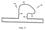
図7は、補助バルーン30の別の実施形態の断面図を示す。この実施形態では、第2の部分34は非対称の形状からなる。第2の部分34の第1側面40は、第1の部分32の側壁33とほぼ平行に伸びる、第1の部分32の側壁33の延長部分を含んでなる。第2の部分34の第2側面42は、第1の部分32から張り出す外方向伸長部分44を含んでなる。
FIG. 7 shows a cross-sectional view of another embodiment of the
いくつかの実施形態では、第1および第2の部分32、34は、第1の膨張圧において管状のほぼ対称的な形状を呈し、第2の部分34はさらに、より高い第2の圧力において外方向伸長部分44を有する非対称の形状へと拡張することになる。
In some embodiments, the first and
上記の開示は、実例であるが網羅的なものではないように意図されている。この説明から、当業者には多くの変形物および代替物が示唆されるであろう。個々の図面において示し、上記に説明した様々な要素は、所望どおりに組み合わせることもできるし、組み合わせのために改変することもできる。これらの代替物および変形物はすべて、特許請求の範囲の範囲内に含まれるべく意図されており、特許請求の範囲において用語「含む、含んでなる」は、「含むがこれに限定されるものではない」ことを意味する。 The above disclosure is intended to be illustrative but not exhaustive. This description will suggest many variations and alternatives to one of ordinary skill in this art. The various elements shown in the individual drawings and described above can be combined as desired or modified for combination. All these alternatives and variations are intended to be included within the scope of the claims, and in the claims, the term “comprising” includes “but is not limited to” Means not.
さらに、従属クレームにおいて提示される特定の特徴は、本発明の範囲内で別の組み合わせかたで互いに組み合わせることが可能であり、従って本発明は、従属クレームの特徴の任意の他の可能な組み合わせを有する他の実施形態をも明確に対象とするものとして認識されるべきである。例えば、クレームの公開にあたって、複数従属形式がその管轄域において容認された形式である場合、後続するあらゆる従属クレームは、先行する全てのクレームに従属する複数従属形式に書き換えられ、そのような従属クレームにおいて引用されたすべての先行内容を有するようにすべきである(例えば、クレーム1に直接従属するクレームはそれぞれ、先行するすべてのクレームに従属するものとして書き換えられるべきである)。複数従属クレーム形式が制限される管轄域では、後続する従属クレームを、そのような従属クレーム中に記載された特定のクレーム以外の先行内容を有する先行クレームに従属させる、各々が単数従属するクレーム形式にもそれぞれ書き換えるべきである。 Furthermore, the particular features presented in the dependent claims can be combined with each other in other combinations within the scope of the present invention, and thus the present invention may be any other possible combination of the features of the dependent claims. It should be recognized that other embodiments having: are also explicitly targeted. For example, when publishing a claim, if the multiple dependent form is an accepted form in that jurisdiction, any subsequent dependent claims will be rewritten to a multiple dependent form dependent on all preceding claims, and such dependent claims Should have all the previous content cited in (e.g., each claim directly dependent on claim 1 should be rewritten as dependent on all preceding claims). In jurisdictions where multiple dependent claim forms are restricted, the dependent form of a subsequent dependent claim is subject to a preceding claim having preceding content other than the specific claim stated in such dependent claim. Should also be rewritten.
ここで本発明の説明を終える。当業者であれば、本明細書に記載された特定の実施形態についての別の等価物(いずれの等価物も本明細書に添付の特許請求の範囲に包含されるように意図される)を認識することができよう。 This is the end of the description of the present invention. Those skilled in the art will recognize other equivalents for the specific embodiments described herein (any equivalent is intended to be encompassed by the claims appended hereto). I can recognize it.
このPCT出願は、2006年8月23日出願の米国特許出願第11/508,692号の優先権を主張し、前記米国出願の全内容は参照により本願に組込まれる。 This PCT application claims priority from US patent application Ser. No. 11 / 508,692, filed Aug. 23, 2006, the entire contents of which are incorporated herein by reference.
Claims (12)
内部にカテーテルルーメンを有するカテーテルシャフトと、
主要バルーンと、
内部に分枝ルーメンを有する側枝シャフトと、
第1の花弁と第2の花弁とを含む側枝花弁構造を含むステントであって、該第1の花弁は該第2の花弁から側枝花弁構造を横切って配置されるとともに第1の位置にて展開されるように構成され、該第2の花弁は第2の位置にて展開されるように構成され、該第1の位置と該第2の位置との間を所定の距離が延在する、前記ステントと、
該第1の花弁と該第2の花弁とを展開するように構成される補助バルーンと
を含んでなり、補助バルーンは、分枝ルーメンと流体連通している内部体積を有する膨張可能な本体部分を含んでなり、膨張可能な本体部分は、第1の部分および第2の部分を含んでなり、第2の部分は第1の部分より大きな断面積を有し、第1の部分は第2の部分よりも主要バルーンの近くに位置しており、該第1の部分を横切る距離は前記所定の距離より小さく、該第2の部分を横切る距離は前記所定の距離より大きく、
該補助バルーンは第1の膨張圧において円筒形をなし、
該第2の部分は、より高い第2の膨張圧において、第1の部分より張り出す外方向伸長部分を有する形状を呈することを特徴とする、バルーン付きカテーテル。 A balloon catheter,
A catheter shaft having a catheter lumen therein;
The main balloon,
A side branch shaft having a branch lumen therein;
A stent comprising a side branch petal structure including a first petal and a second petal, wherein the first petal is disposed across the side branch petal structure from the second petal and in a first position. Configured to be deployed, the second petal is configured to be deployed at a second position, and a predetermined distance extends between the first position and the second position The stent;
An inflatable body portion having an internal volume in fluid communication with the branch lumen, the auxiliary balloon configured to deploy the first petal and the second petal. The inflatable body portion comprises a first portion and a second portion , the second portion having a larger cross-sectional area than the first portion, wherein the first portion is the second portion. Is located closer to the main balloon than the first portion, the distance across the first portion is less than the predetermined distance, the distance across the second portion is greater than the predetermined distance,
The auxiliary balloon is cylindrical at the first inflation pressure;
The second portion is in the second higher inflation pressure, characterized Teisu the Rukoto a shape having outwardly extending portion projecting from the first portion, the catheter with the balloon.
内部にカテーテルルーメンを有するカテーテルシャフトと、
主要バルーンと、
内部に分枝ルーメンを有する側枝シャフトと、
補助バルーンと
を含んでなり、補助バルーンは、分枝ルーメンと流体連通している内部体積を有する膨張可能な本体部分を含んでなり、膨張可能な本体部分は、第1の部分および第2の部分を含んでなり、第1の部分の形状は円筒形であり、第2の部分は第1の部分より大きな断面積を有し、第1の部分は第2の部分よりも主要バルーンの近くに位置しており、
第2の部分は、補助バルーンの中心軸をはさんで非対称な形状を含んでなることを特徴とする、バルーン付きカテーテル。 A balloon catheter,
A catheter shaft having a catheter lumen therein;
The main balloon,
A side branch shaft having a branch lumen therein;
With an auxiliary balloon
The auxiliary balloon includes an inflatable body portion having an interior volume in fluid communication with the branch lumen, the inflatable body portion including a first portion and a second portion. The first part has a cylindrical shape, the second part has a larger cross-sectional area than the first part, and the first part is located closer to the main balloon than the second part. And
A catheter with a balloon characterized in that the second part comprises an asymmetric shape across the central axis of the auxiliary balloon.
内部にカテーテルルーメンを有するカテーテルシャフトと、
主要バルーンと、
内部に分枝ルーメンを有する側枝シャフトと、
第1の花弁と第2の花弁とを含む側枝花弁構造を含むステントであって、該第1の花弁は該第2の花弁から側枝花弁構造を横切って配置されるとともに第1の位置にて展開されるように構成され、該第2の花弁は第2の位置にて展開されるように構成され、該第1の位置と該第2の位置との間を所定の距離が延在する、前記ステントと、
該第1の花弁と該第2の花弁とを展開するように構成される補助バルーンと
を含んでなり、補助バルーンは、分枝ルーメンと流体連通している内部体積を有する膨張可能な本体部分を含んでなり、膨張可能な本体部分は、第1の部分および第2の部分を含んでなり、第2の部分は第1の部分より大きな断面積を有し、第1の部分は第2の部分よりも主要バルーンの近くに位置しており、該第1の部分を横切る距離は前記所定の距離より小さく、該第2の部分を横切る距離は前記所定の距離より大きく、
補助バルーンは、同補助バルーンが膨張すると側枝分岐部における各花弁を少なくとも100度展開するために構築および配置構成されることを特徴とする、バルーン付きカテーテル。 A balloon catheter,
A catheter shaft having a catheter lumen therein;
The main balloon,
A side branch shaft having a branch lumen therein;
A stent comprising a side branch petal structure including a first petal and a second petal, wherein the first petal is disposed across the side branch petal structure from the second petal and in a first position. Configured to be deployed, the second petal is configured to be deployed at a second position, and a predetermined distance extends between the first position and the second position The stent;
An auxiliary balloon configured to deploy the first petal and the second petal;
The auxiliary balloon includes an inflatable body portion having an interior volume in fluid communication with the branch lumen, the inflatable body portion including a first portion and a second portion. The second part has a larger cross-sectional area than the first part, the first part is located closer to the main balloon than the second part, and the distance across the first part is Less than the predetermined distance and a distance across the second portion is greater than the predetermined distance;
The secondary balloon, you wherein the construction and arrangement configured for the auxiliary balloon to expand at least 100 degrees each petal in the inflated side branch bifurcation balloon catheter.
Applications Claiming Priority (3)
| Application Number | Priority Date | Filing Date | Title |
|---|---|---|---|
| US11/508,692 US8177829B2 (en) | 2006-08-23 | 2006-08-23 | Auxiliary balloon catheter |
| US11/508,692 | 2006-08-23 | ||
| PCT/US2007/017889 WO2008024220A1 (en) | 2006-08-23 | 2007-08-14 | Auxiliary balloon catheter |
Publications (3)
| Publication Number | Publication Date |
|---|---|
| JP2010501249A JP2010501249A (en) | 2010-01-21 |
| JP2010501249A5 JP2010501249A5 (en) | 2010-11-11 |
| JP5220016B2 true JP5220016B2 (en) | 2013-06-26 |
Family
ID=38785159
Family Applications (1)
| Application Number | Title | Priority Date | Filing Date |
|---|---|---|---|
| JP2009525559A Expired - Fee Related JP5220016B2 (en) | 2006-08-23 | 2007-08-14 | Catheter with auxiliary balloon |
Country Status (5)
| Country | Link |
|---|---|
| US (1) | US8177829B2 (en) |
| EP (1) | EP2056916B1 (en) |
| JP (1) | JP5220016B2 (en) |
| CA (1) | CA2658428A1 (en) |
| WO (1) | WO2008024220A1 (en) |
Families Citing this family (23)
| Publication number | Priority date | Publication date | Assignee | Title |
|---|---|---|---|---|
| US20040226556A1 (en) | 2003-05-13 | 2004-11-18 | Deem Mark E. | Apparatus for treating asthma using neurotoxin |
| US7850645B2 (en) * | 2005-02-11 | 2010-12-14 | Boston Scientific Scimed, Inc. | Internal medical devices for delivery of therapeutic agent in conjunction with a source of electrical power |
| EP2194934A1 (en) * | 2007-08-27 | 2010-06-16 | Boston Scientific Limited | Bulging balloon for bifurcation catheter assembly and methods |
| US20090069878A1 (en) * | 2007-08-27 | 2009-03-12 | Boston Scientific Scimed, Inc. | Bifurcation post-dilatation balloon and methods |
| US8936567B2 (en) | 2007-11-14 | 2015-01-20 | Boston Scientific Scimed, Inc. | Balloon bifurcated lumen treatment |
| US8483831B1 (en) | 2008-02-15 | 2013-07-09 | Holaira, Inc. | System and method for bronchial dilation |
| JP2011519699A (en) | 2008-05-09 | 2011-07-14 | インノブアトイブエ プルモナルイ ソルウトイオンス,インコーポレイティッド | Systems, assemblies and methods for treatment of bronchial trees |
| EP2300093B1 (en) | 2008-06-05 | 2016-04-20 | Boston Scientific Scimed, Inc. | Deflatable bifurcated device |
| US20090326643A1 (en) * | 2008-06-27 | 2009-12-31 | Boston Scientific Scimed, Inc. | Balloon folding apparatus and method |
| WO2010065530A1 (en) * | 2008-12-01 | 2010-06-10 | Ams Research Corporation | Combined catheter tip and inflation balloon |
| EP2398426A2 (en) * | 2009-02-23 | 2011-12-28 | John To | Stent strut appositioner |
| KR101722290B1 (en) * | 2009-10-27 | 2017-03-31 | 호라이라 인코포레이티드 | Delivery devices with coolable energy emitting assemblies |
| US8911439B2 (en) | 2009-11-11 | 2014-12-16 | Holaira, Inc. | Non-invasive and minimally invasive denervation methods and systems for performing the same |
| CN102711645B (en) | 2009-11-11 | 2016-12-28 | 赫莱拉公司 | For processing tissue and controlling narrow system and device |
| US10512761B2 (en) | 2009-12-02 | 2019-12-24 | Renovorx, Inc. | Methods for delivery of therapeutic materials to treat pancreatic cancer |
| US9457171B2 (en) | 2009-12-02 | 2016-10-04 | Renovorx, Inc. | Devices, methods and kits for delivery of therapeutic materials to a target artery |
| ES2828722T3 (en) | 2009-12-02 | 2021-05-27 | Renovorx Inc | Devices and kits for delivery of therapeutic materials to a pancreas |
| ES2346283B1 (en) | 2010-03-03 | 2011-09-05 | Miguel Salamanques Claver | CONTROL SYSTEM AND MANAGEMENT OF ENERGY RECHARGE, COMMUNICATION AND LIGHTING. |
| US9398933B2 (en) | 2012-12-27 | 2016-07-26 | Holaira, Inc. | Methods for improving drug efficacy including a combination of drug administration and nerve modulation |
| WO2014197362A1 (en) | 2013-06-03 | 2014-12-11 | Ramtin Agah | Devices, methods and kits for delivery of therapeutic materials to a pancreas |
| US10695543B2 (en) | 2017-05-18 | 2020-06-30 | Renovorx, Inc. | Methods for treating cancerous tumors |
| US11052224B2 (en) | 2017-05-18 | 2021-07-06 | Renovorx, Inc. | Methods for treating cancerous tumors |
| CN116271444A (en) * | 2022-11-25 | 2023-06-23 | 广州易介医疗科技有限公司 | Balloon type auxiliary catheter and use method thereof |
Family Cites Families (37)
| Publication number | Priority date | Publication date | Assignee | Title |
|---|---|---|---|---|
| US4896670A (en) * | 1988-04-19 | 1990-01-30 | C. R. Bard, Inc. | Kissing balloon catheter |
| US4906244A (en) * | 1988-10-04 | 1990-03-06 | Cordis Corporation | Balloons for medical devices and fabrication thereof |
| DE69433506T2 (en) * | 1993-10-01 | 2004-06-24 | Boston Scientific Corp., Natick | MEDICAL, THERMOPLASTIC ELASTOMER CONTAINING BALLOONS |
| US5607444A (en) * | 1993-12-02 | 1997-03-04 | Advanced Cardiovascular Systems, Inc. | Ostial stent for bifurcations |
| JP3494654B2 (en) * | 1994-03-02 | 2004-02-09 | シメッド ライフ システムズ インコーポレイテッド | Block copolymer elastomer, catheter, balloon |
| US5613980A (en) * | 1994-12-22 | 1997-03-25 | Chauhan; Tusharsindhu C. | Bifurcated catheter system and method |
| US5749851A (en) * | 1995-03-02 | 1998-05-12 | Scimed Life Systems, Inc. | Stent installation method using balloon catheter having stepped compliance curve |
| NL9500468A (en) * | 1995-03-08 | 1996-10-01 | Cordis Europ | Balloon catheter and method of making it. |
| FR2733682B1 (en) * | 1995-05-04 | 1997-10-31 | Dibie Alain | ENDOPROSTHESIS FOR THE TREATMENT OF STENOSIS ON BIFURCATIONS OF BLOOD VESSELS AND LAYING EQUIPMENT THEREFOR |
| US5669924A (en) * | 1995-10-26 | 1997-09-23 | Shaknovich; Alexander | Y-shuttle stent assembly for bifurcating vessels and method of using the same |
| EP0944366B1 (en) * | 1996-11-04 | 2006-09-13 | Advanced Stent Technologies, Inc. | Extendible double stent |
| US5749890A (en) * | 1996-12-03 | 1998-05-12 | Shaknovich; Alexander | Method and system for stent placement in ostial lesions |
| US5720735A (en) * | 1997-02-12 | 1998-02-24 | Dorros; Gerald | Bifurcated endovascular catheter |
| US6242063B1 (en) * | 1997-09-10 | 2001-06-05 | Scimed Life Systems, Inc. | Balloons made from liquid crystal polymer blends |
| US6284333B1 (en) * | 1997-09-10 | 2001-09-04 | Scimed Life Systems, Inc. | Medical devices made from polymer blends containing low melting temperature liquid crystal polymers |
| US5938582A (en) * | 1997-09-26 | 1999-08-17 | Medtronic, Inc. | Radiation delivery centering catheter |
| DE69830227T2 (en) * | 1997-11-07 | 2006-02-02 | Ave Connaught | BALLOON CATHETER FOR THE REPAIR OF REFILLING BLOOD VESSELS |
| US5948345A (en) * | 1998-01-05 | 1999-09-07 | Medtronic, Inc. | Method for making medical balloon catheter |
| US6099497A (en) * | 1998-03-05 | 2000-08-08 | Scimed Life Systems, Inc. | Dilatation and stent delivery system for bifurcation lesions |
| US6129738A (en) * | 1998-06-20 | 2000-10-10 | Medtronic Ave, Inc. | Method and apparatus for treating stenoses at bifurcated regions |
| US6117117A (en) * | 1998-08-24 | 2000-09-12 | Advanced Cardiovascular Systems, Inc. | Bifurcated catheter assembly |
| US6017324A (en) * | 1998-10-20 | 2000-01-25 | Tu; Lily Chen | Dilatation catheter having a bifurcated balloon |
| US7655030B2 (en) * | 2003-07-18 | 2010-02-02 | Boston Scientific Scimed, Inc. | Catheter balloon systems and methods |
| US20050060027A1 (en) * | 1999-01-13 | 2005-03-17 | Advanced Stent Technologies, Inc. | Catheter balloon systems and methods |
| CA2379670A1 (en) | 1999-08-12 | 2001-02-22 | Wilson-Cook Medical Inc. | Dilation balloon having multiple diameters |
| US6325780B1 (en) * | 1999-09-13 | 2001-12-04 | Advanced Cardiovascular Systems, Inc. | Inflatable member formed of liquid crystal polymeric material blend |
| US6270522B1 (en) * | 1999-12-21 | 2001-08-07 | Advanced Cardiovascular Systems, Inc. | High pressure catheter balloon |
| JP2002078809A (en) * | 2000-09-07 | 2002-03-19 | Shutaro Satake | Balloon catheter for electrically isolating pulmonary vein |
| US6764504B2 (en) * | 2001-01-04 | 2004-07-20 | Scimed Life Systems, Inc. | Combined shaped balloon and stent protector |
| WO2002067653A2 (en) * | 2001-02-26 | 2002-09-06 | Scimed Life Systems, Inc. | Bifurcated stent and delivery system |
| US6749628B1 (en) * | 2001-05-17 | 2004-06-15 | Advanced Cardiovascular Systems, Inc. | Stent and catheter assembly and method for treating bifurcations |
| US20030163082A1 (en) * | 2002-02-26 | 2003-08-28 | Mertens Steven P. | Lumen weld |
| ITBS20020017A1 (en) | 2002-03-01 | 2003-09-01 | Invatec Srl | CATHETER WITH BRANCHES AND WITH A BALLOON ON EACH BRANCH |
| EP1369097A1 (en) | 2002-06-07 | 2003-12-10 | CathNet-Science Holding A/S | Balloon catheter assembly |
| US7407507B2 (en) * | 2003-06-18 | 2008-08-05 | Nipro Corporation | Balloon catheter suited to kissing techniques |
| US7344557B2 (en) * | 2003-11-12 | 2008-03-18 | Advanced Stent Technologies, Inc. | Catheter balloon systems and methods |
| JP2007536057A (en) * | 2004-05-06 | 2007-12-13 | インヴァテック エス.アール.エル. | Bifurcation catheter |
-
2006
- 2006-08-23 US US11/508,692 patent/US8177829B2/en not_active Expired - Fee Related
-
2007
- 2007-08-14 EP EP07836754.7A patent/EP2056916B1/en not_active Not-in-force
- 2007-08-14 CA CA002658428A patent/CA2658428A1/en not_active Abandoned
- 2007-08-14 JP JP2009525559A patent/JP5220016B2/en not_active Expired - Fee Related
- 2007-08-14 WO PCT/US2007/017889 patent/WO2008024220A1/en active Application Filing
Also Published As
| Publication number | Publication date |
|---|---|
| EP2056916B1 (en) | 2013-11-06 |
| CA2658428A1 (en) | 2008-02-28 |
| US20080097464A1 (en) | 2008-04-24 |
| EP2056916A1 (en) | 2009-05-13 |
| WO2008024220A1 (en) | 2008-02-28 |
| US8177829B2 (en) | 2012-05-15 |
| JP2010501249A (en) | 2010-01-21 |
Similar Documents
| Publication | Publication Date | Title |
|---|---|---|
| JP5220016B2 (en) | Catheter with auxiliary balloon | |
| US7175607B2 (en) | Catheter balloon liner with variable thickness and method for making same | |
| US7195638B1 (en) | Catheter balloon | |
| US9707381B2 (en) | Non-compliant multilayered balloon for a catheter | |
| EP1761295B1 (en) | Cutting balloon and process | |
| US7226472B2 (en) | Catheter balloon with advantageous cone design | |
| JP5070215B2 (en) | Bifurcated catheter assembly | |
| US6391002B1 (en) | Balloon with the variable radial force distribution | |
| US20140066898A1 (en) | Retractable sheath devices, systems, and methods | |
| EP2134404B1 (en) | Balloon fold design for deployment of bifurcated stent petal architecture | |
| JP2008519612A (en) | Catheter balloon system and method | |
| US20060136032A1 (en) | Balloon catheter having a balloon with hybrid porosity sublayers | |
| JP2002512862A (en) | Catheter balloon with multiple deflected vanes | |
| EP2968840B1 (en) | Method of forming reduced material tip for catheter | |
| US20220323728A1 (en) | Method for producing balloon catheter | |
| JP2007521103A (en) | Balloon assembly with torque | |
| JP2006512999A (en) | Mold for forming medical balloons | |
| US7025745B2 (en) | Method of making a catheter balloon using a tapered mandrel | |
| WO2003039628A2 (en) | Balloon catheter with non-slip balloon | |
| US10251765B2 (en) | Stent delivery system and manufacturing method for the same | |
| JP4373599B2 (en) | Biological organ dilator | |
| JP5497153B2 (en) | Balloon catheter and balloon | |
| CN116685370A (en) | Balloon for balloon catheter | |
| CN116635105A (en) | Balloon for balloon catheter |
Legal Events
| Date | Code | Title | Description |
|---|---|---|---|
| A621 | Written request for application examination |
Free format text: JAPANESE INTERMEDIATE CODE: A621 Effective date: 20100811 |
|
| A521 | Written amendment |
Free format text: JAPANESE INTERMEDIATE CODE: A523 Effective date: 20100917 |
|
| RD04 | Notification of resignation of power of attorney |
Free format text: JAPANESE INTERMEDIATE CODE: A7424 Effective date: 20120302 |
|
| A977 | Report on retrieval |
Free format text: JAPANESE INTERMEDIATE CODE: A971007 Effective date: 20120305 |
|
| A131 | Notification of reasons for refusal |
Free format text: JAPANESE INTERMEDIATE CODE: A131 Effective date: 20120410 |
|
| A601 | Written request for extension of time |
Free format text: JAPANESE INTERMEDIATE CODE: A601 Effective date: 20120710 |
|
| A602 | Written permission of extension of time |
Free format text: JAPANESE INTERMEDIATE CODE: A602 Effective date: 20120718 |
|
| A521 | Written amendment |
Free format text: JAPANESE INTERMEDIATE CODE: A523 Effective date: 20120810 |
|
| TRDD | Decision of grant or rejection written | ||
| A01 | Written decision to grant a patent or to grant a registration (utility model) |
Free format text: JAPANESE INTERMEDIATE CODE: A01 Effective date: 20130219 |
|
| A61 | First payment of annual fees (during grant procedure) |
Free format text: JAPANESE INTERMEDIATE CODE: A61 Effective date: 20130305 |
|
| FPAY | Renewal fee payment (event date is renewal date of database) |
Free format text: PAYMENT UNTIL: 20160315 Year of fee payment: 3 |
|
| R150 | Certificate of patent or registration of utility model |
Free format text: JAPANESE INTERMEDIATE CODE: R150 |
|
| R250 | Receipt of annual fees |
Free format text: JAPANESE INTERMEDIATE CODE: R250 |
|
| R250 | Receipt of annual fees |
Free format text: JAPANESE INTERMEDIATE CODE: R250 |
|
| LAPS | Cancellation because of no payment of annual fees |