JP5215812B2 - Illumination condition determination method, program, exposure method, and device manufacturing method - Google Patents
Illumination condition determination method, program, exposure method, and device manufacturing method Download PDFInfo
- Publication number
- JP5215812B2 JP5215812B2 JP2008278611A JP2008278611A JP5215812B2 JP 5215812 B2 JP5215812 B2 JP 5215812B2 JP 2008278611 A JP2008278611 A JP 2008278611A JP 2008278611 A JP2008278611 A JP 2008278611A JP 5215812 B2 JP5215812 B2 JP 5215812B2
- Authority
- JP
- Japan
- Prior art keywords
- pattern
- illumination condition
- substrate
- reticle
- illumination
- Prior art date
- Legal status (The legal status is an assumption and is not a legal conclusion. Google has not performed a legal analysis and makes no representation as to the accuracy of the status listed.)
- Expired - Fee Related
Links
- 238000005286 illumination Methods 0.000 title claims description 219
- 238000000034 method Methods 0.000 title claims description 58
- 238000004519 manufacturing process Methods 0.000 title claims description 10
- 239000000758 substrate Substances 0.000 claims description 98
- 238000004364 calculation method Methods 0.000 claims description 32
- 238000013178 mathematical model Methods 0.000 claims description 22
- 238000000059 patterning Methods 0.000 claims description 14
- 238000001459 lithography Methods 0.000 claims description 13
- 238000012546 transfer Methods 0.000 description 44
- 238000011156 evaluation Methods 0.000 description 17
- 238000005457 optimization Methods 0.000 description 11
- 238000012545 processing Methods 0.000 description 11
- 230000003287 optical effect Effects 0.000 description 10
- 238000010586 diagram Methods 0.000 description 8
- 238000009826 distribution Methods 0.000 description 8
- 238000004422 calculation algorithm Methods 0.000 description 4
- 238000010276 construction Methods 0.000 description 3
- 239000004065 semiconductor Substances 0.000 description 3
- 230000035945 sensitivity Effects 0.000 description 3
- 241000153282 Theope Species 0.000 description 2
- 230000004075 alteration Effects 0.000 description 2
- 238000002474 experimental method Methods 0.000 description 2
- 238000000605 extraction Methods 0.000 description 2
- 230000002068 genetic effect Effects 0.000 description 2
- 239000011295 pitch Substances 0.000 description 2
- 238000003860 storage Methods 0.000 description 2
- 238000012935 Averaging Methods 0.000 description 1
- 238000000342 Monte Carlo simulation Methods 0.000 description 1
- 241000448053 Toya Species 0.000 description 1
- 238000011161 development Methods 0.000 description 1
- 230000000694 effects Effects 0.000 description 1
- 238000005530 etching Methods 0.000 description 1
- 238000002986 genetic algorithm method Methods 0.000 description 1
- 239000004973 liquid crystal related substance Substances 0.000 description 1
- 238000012067 mathematical method Methods 0.000 description 1
- 238000012858 packaging process Methods 0.000 description 1
- 210000001747 pupil Anatomy 0.000 description 1
- 238000011160 research Methods 0.000 description 1
- 238000004088 simulation Methods 0.000 description 1
- 230000008685 targeting Effects 0.000 description 1
Images


Classifications
-
- G—PHYSICS
- G03—PHOTOGRAPHY; CINEMATOGRAPHY; ANALOGOUS TECHNIQUES USING WAVES OTHER THAN OPTICAL WAVES; ELECTROGRAPHY; HOLOGRAPHY
- G03F—PHOTOMECHANICAL PRODUCTION OF TEXTURED OR PATTERNED SURFACES, e.g. FOR PRINTING, FOR PROCESSING OF SEMICONDUCTOR DEVICES; MATERIALS THEREFOR; ORIGINALS THEREFOR; APPARATUS SPECIALLY ADAPTED THEREFOR
- G03F7/00—Photomechanical, e.g. photolithographic, production of textured or patterned surfaces, e.g. printing surfaces; Materials therefor, e.g. comprising photoresists; Apparatus specially adapted therefor
- G03F7/70—Microphotolithographic exposure; Apparatus therefor
- G03F7/70058—Mask illumination systems
- G03F7/70141—Illumination system adjustment, e.g. adjustments during exposure or alignment during assembly of illumination system
-
- G—PHYSICS
- G03—PHOTOGRAPHY; CINEMATOGRAPHY; ANALOGOUS TECHNIQUES USING WAVES OTHER THAN OPTICAL WAVES; ELECTROGRAPHY; HOLOGRAPHY
- G03F—PHOTOMECHANICAL PRODUCTION OF TEXTURED OR PATTERNED SURFACES, e.g. FOR PRINTING, FOR PROCESSING OF SEMICONDUCTOR DEVICES; MATERIALS THEREFOR; ORIGINALS THEREFOR; APPARATUS SPECIALLY ADAPTED THEREFOR
- G03F7/00—Photomechanical, e.g. photolithographic, production of textured or patterned surfaces, e.g. printing surfaces; Materials therefor, e.g. comprising photoresists; Apparatus specially adapted therefor
- G03F7/70—Microphotolithographic exposure; Apparatus therefor
- G03F7/70483—Information management; Active and passive control; Testing; Wafer monitoring, e.g. pattern monitoring
- G03F7/70491—Information management, e.g. software; Active and passive control, e.g. details of controlling exposure processes or exposure tool monitoring processes
- G03F7/705—Modelling or simulating from physical phenomena up to complete wafer processes or whole workflow in wafer productions
-
- G—PHYSICS
- G03—PHOTOGRAPHY; CINEMATOGRAPHY; ANALOGOUS TECHNIQUES USING WAVES OTHER THAN OPTICAL WAVES; ELECTROGRAPHY; HOLOGRAPHY
- G03F—PHOTOMECHANICAL PRODUCTION OF TEXTURED OR PATTERNED SURFACES, e.g. FOR PRINTING, FOR PROCESSING OF SEMICONDUCTOR DEVICES; MATERIALS THEREFOR; ORIGINALS THEREFOR; APPARATUS SPECIALLY ADAPTED THEREFOR
- G03F7/00—Photomechanical, e.g. photolithographic, production of textured or patterned surfaces, e.g. printing surfaces; Materials therefor, e.g. comprising photoresists; Apparatus specially adapted therefor
- G03F7/70—Microphotolithographic exposure; Apparatus therefor
- G03F7/70483—Information management; Active and passive control; Testing; Wafer monitoring, e.g. pattern monitoring
- G03F7/70605—Workpiece metrology
- G03F7/70616—Monitoring the printed patterns
- G03F7/70625—Dimensions, e.g. line width, critical dimension [CD], profile, sidewall angle or edge roughness
Description
本発明は、半導体デバイス製造に係るリソグラフィ工程における照明条件の決定方法、プログラム、露光方法及びデバイス製造方法に関する。 The present invention relates to an illumination condition determination method, a program, an exposure method, and a device manufacturing method in a lithography process related to semiconductor device manufacturing.
半導体製造のリソグラフィ現場ではレチクル(マスク)を用い、所定のパターニングを行っている。しかし、新規の露光装置を導入した場合、その性能が既存の露光装置と同一ではないので、従来と同じ転写パターンを得るためには、その新規の露光装置を調整する必要がある。 In a lithography field of semiconductor manufacturing, a reticle (mask) is used to perform predetermined patterning. However, when a new exposure apparatus is introduced, its performance is not the same as that of the existing exposure apparatus. Therefore, in order to obtain the same transfer pattern as before, it is necessary to adjust the new exposure apparatus.
また、デバイス特性の向上のために、現状の転写パターンを若干変更させる必要性が出てくることがある。本来はレチクルを再作成するべきであるが、わずかな変更のために高価なレチクルを再作成するのではなく、露光装置を調整することにより目標パターンを形成することが望まれる。 In addition, in order to improve device characteristics, it may be necessary to slightly change the current transfer pattern. Originally, the reticle should be recreated, but it is desirable to form the target pattern by adjusting the exposure apparatus rather than recreating an expensive reticle for slight changes.
基板(ウエハ)上のパターン形状に影響を与える露光パラメータとして、照明強度の分布、レンズのNA、レンズの収差、光源の波長幅等があるが、最も影響を与える露光パラメータは照明形状等の照明条件である。NAも影響力があるが、パラメータが数値一つであるため、部分的な調整が困難であるし、解像性を変化させてしまう。収差も影響力を持つが、最新の露光装置ではその量が小さく、寄与率は小さい。よって、照明条件を調整して、目的を達成するのが一般的である。 Exposure parameters that affect the pattern shape on the substrate (wafer) include illumination intensity distribution, lens NA, lens aberration, and light source wavelength width. The exposure parameters that affect the most are illumination such as illumination shape. It is a condition. NA is also influential, but since the parameter is a single numerical value, partial adjustment is difficult and resolution is changed. Although aberrations also have an influence, the amount of the latest exposure apparatus is small and the contribution rate is small. Therefore, it is common to achieve the purpose by adjusting the illumination conditions.
転写パターンをある目標値に変形させる作業法には以下の二つの手法がある。以下の説明において照明形状は一般的に数値パラメータで表現することができることを前提にしている。例えば、輪帯照明の場合は外σ、内σで表現される。 There are the following two methods for changing the transfer pattern to a certain target value. In the following description, it is assumed that the illumination shape can be generally expressed by numerical parameters. For example, in the case of annular illumination, it is expressed by outer σ and inner σ.
[手法1]
最初に評価点毎に各照明形状パラメータの変化に対する寸法の変化率(以下、「敏感度」と呼ぶ。)を求める。そして各評価点の現状から目標への寸法変化量を敏感度で割って各照明形状パラメータの変化させるべき値を求める。この場合、寸法の変化量は通常数nmレベルであり、この範囲では線形であると仮定しても大きな誤差にはならない。また、敏感度を求めるにあたり、光学像の計算で行うのが簡便であるが、実験値と差が発生するため、実際に照明条件を微小変化させて、寸法を測定するという手法をとる。この手法は、非特許文献1に示されている。
[Method 1]
First, a dimensional change rate (hereinafter referred to as “sensitivity”) with respect to a change in each illumination shape parameter is obtained for each evaluation point. Then, the dimensional change from the current state of each evaluation point to the target is divided by the sensitivity to obtain a value to be changed for each illumination shape parameter. In this case, the amount of change in dimensions is usually on the order of several nanometers, and even if it is assumed to be linear in this range, there is no significant error. Further, when obtaining the sensitivity, it is easy to calculate the optical image, but since a difference from the experimental value occurs, a method of actually changing the illumination condition and measuring the dimension is adopted. This technique is shown in
[手法2]
ある照明条件においてウエハ上のパターンの輪郭を計算し、その輪郭とパターン調整を行う複数場所での目標値との差分からなる集合のrms(root mean square)又は最大値を求める。そしてこれを指標値とする。次に照明条件を若干変更し、その指標値を求める。これを照明条件空間内で繰り返し、指標値が最小になる照明条件を求める。求める方法としては遺伝アルゴリズム法やモンテカルロ法等の数学的手法を用いる。この手法は、非特許文献2に示されている。
[Method 2]
The contour of the pattern on the wafer is calculated under certain illumination conditions, and the rms (root mean square) or maximum value of the set consisting of the difference between the contour and the target value at a plurality of locations where pattern adjustment is performed is obtained. This is used as an index value. Next, the illumination condition is slightly changed, and the index value is obtained. This is repeated in the illumination condition space to obtain an illumination condition that minimizes the index value. As a method for obtaining it, a mathematical method such as a genetic algorithm method or a Monte Carlo method is used. This technique is shown in Non-Patent Document 2.
ウエハ上のパターンは光学像の計算又はレジスト像の計算によって行われるが、本分野では実験との整合が必要であるため、基本的にはレジスト像の計算を用いる。 The pattern on the wafer is calculated by calculating an optical image or calculating a resist image. In this field, however, it is necessary to match with an experiment. Therefore, calculation of a resist image is basically used.
レジスト像の計算には、物理的に厳密に計算するものと、実験値と光学像計算との相関からレジスト計算するものとがあるが、前者は計算時間が長いという問題点を有しているため、本発明では後述の特徴を有した計算時間が早い後者を使用する。 There are two types of resist image calculations: those that are physically strictly calculated, and those that calculate resists based on the correlation between experimental values and optical image calculations, but the former has the problem of a long calculation time. For this reason, in the present invention, the latter having the characteristics described later and having a fast calculation time is used.
ここでそのレジスト像を用いる計算方法を説明する。まず実験による転写、測定を行うパターンとして単純ラインアンドスペースやライン端からなるモデル抽出パターンを数種選定する。パターン種は数種であるが、それぞれの線幅、スペース幅、ライン端幅は数10~100種ある。 Here, a calculation method using the resist image will be described. First, several types of model extraction patterns consisting of simple lines and spaces and line ends are selected as patterns to be transferred and measured by experiments. There are several types of patterns, but there are several types of line width, space width, and line end width of several 10 to 100 types.
これらの重要箇所に対し、光学像からログスロープ(image log slope:ILS)と曲率(curvature)を計算する。ILSは下記の式で定義される。
ILS= d ln(I) / d x (Iは光強度、xは位置)
curvatureは輪郭を小分割し、それぞれの曲線を円の一部でフィッティングし、その半径をcurvatureとする。そして、その箇所の実験値と光学像計算値の寸法差分δを下記の式で表現する。
δ=a×Curvature + b×ILS + c (a、b、cは定数)
これらを評価点全てに対してフィティングを行い、a、b、cを決定する。この関係式を構築することをモデル構築と呼ぶ。これが決定されればパターンの任意の場所で、光学像からILSとcurvatureを計算することにより上記差分を決定し、それからレジストパターン寸法が算出される。
ILS = d ln (I) / dx (I is light intensity, x is position)
curvature subdivides the contour, fits each curve with a part of a circle, and sets its radius to curvature. Then, the dimensional difference δ between the experimental value and the optical image calculation value at that location is expressed by the following equation.
δ = a × Curvature + b × ILS + c (a, b, c are constants)
These are fitted to all evaluation points to determine a, b, and c. The construction of this relational expression is called model construction. If this is determined, the difference is determined by calculating ILS and curvature from the optical image at an arbitrary position of the pattern, and the resist pattern dimension is calculated therefrom.
手法1においては、評価点が複数の場合、各評価点から求められた照明条件の最適解が異なる場合があり、その場合は、平均化処理や重み付け処理等を行う。しかし、その処理には、物理学的な根拠に基づかないことが多いので、全評価点における総合的なマッチング精度が劣化する。さらには複数存在する照明条件の寄与率も規定する必要がある。これらの処理も物理学的な根拠に基づかないことが多いので、全評価点における総合的なマッチング精度が劣化する。
In
手法2においては、転写パターンを目標値に最も近づける照明条件を数学的に求めている。そのため、算出された解は完全であるはずであるが、数学的処理で使用しているレジスト計算の誤差、照明条件の数値定義と実際の露光装置の設定とのズレ等により、本方法で算出した結果を実際に適用しても誤差が発生する。 In Method 2, an illumination condition that makes the transfer pattern closest to the target value is mathematically obtained. Therefore, although the calculated solution should be complete, it is calculated by this method due to errors in resist calculation used in mathematical processing, deviations between numerical definitions of illumination conditions and actual exposure device settings, etc. Even if the result is actually applied, an error occurs.
以上のような背景を踏まえ、本発明は、基板をパターニングするリソグラフィ工程におけるレチクルの照明条件を高精度かつ容易に決定することを目的とする。 In light of the above background, an object of the present invention is to determine a reticle illumination condition in a lithography process for patterning a substrate with high accuracy and ease.
本発明の第1の側面は、露光装置によりレチクルのパターンを基板に転写して基板をパターニングするリソグラフィ工程における前記レチクルの照明条件を決定する決定方法であって、前記レチクルを用いて基板に形成するべき目標パターンを設定する設定工程と、前記レチクルと第1照明条件を用いる露光を経て基板に転写された第1パターンのデータを取得する取得工程と、照明条件と当該照明条件を用いて基板に転写される仮想のパターンとの関係を規定する数学的モデルを用いて、前記レチクルを用いて前記目標パターンを基板に転写させる仮想の第2照明条件と、前記レチクルを用いて前記第1パターンを基板に転写させる仮想の第3照明条件とを算出する算出工程と、前記算出された第2照明条件と第3照明条件との差分を前記第1照明条件に加えた第4照明条件を、前記レチクルを用いて前記目標パターンを基板に転写する照明条件として決定する決定工程と、を含むことを特徴とする。
A first aspect of the present invention is a determination method for determining an illumination condition of the reticle in a lithography process in which a reticle pattern is transferred to a substrate by an exposure apparatus to pattern the substrate, and is formed on the substrate using the reticle. A setting step of setting a target pattern to be performed, an acquisition step of acquiring data of the first pattern transferred to the substrate through exposure using the reticle and the first illumination condition, and a substrate using the illumination condition and the illumination condition Using a mathematical model that defines a relationship with a virtual pattern transferred to the substrate, a virtual second illumination condition for transferring the target pattern onto a substrate using the reticle, and the first pattern using the reticle Calculating a virtual third illumination condition for transferring the image to the substrate, and calculating a difference between the calculated second illumination condition and the third illumination condition. A fourth illumination condition added to 1 lighting conditions, characterized in that it comprises a and a determination step of determining a lighting condition of transferring to the substrate the target pattern using the reticle.
本発明の第2の側面は、露光装置によりレチクルのパターンを基板に転写して基板をパターニングするリソグラフィ工程における前記レチクルの照明条件を決定する決定方法であって、前記レチクルを用いて基板に形成するべき目標パターンを設定する設定工程と、前記レチクルと第1照明条件を用いる露光を経て基板に転写された第1パターンのデータを取得する取得工程と、照明条件と当該照明条件を用いて基板に転写される仮想のパターンとの関係を規定する数学的モデルを用いて、前記レチクルと前記第1照明条件を用いる露光を経て基板に転写される仮想の第2パターンを算出する第2算出工程と、前記レチクルを用いる露光を経て、前記目標パターンと前記第1パターンとの差分を前記算出された第2パターンに加えた仮想の第3パターンを基板に転写させる仮想の第5照明条件を、前記モデルを用いて算出する第3算出工程と、前記算出された第5照明条件を、前記レチクルを用いて前記目標パターンを基板に転写する照明条件として決定する決定工程と、を含むことを特徴とする。
According to a second aspect of the present invention, there is provided a determination method for determining an illumination condition of the reticle in a lithography process for patterning the substrate by transferring the pattern of the reticle onto the substrate by an exposure apparatus, which is formed on the substrate using the reticle. A setting step of setting a target pattern to be performed, an acquisition step of acquiring data of the first pattern transferred to the substrate through exposure using the reticle and the first illumination condition, and a substrate using the illumination condition and the illumination condition A second calculation step of calculating a virtual second pattern transferred to the substrate through exposure using the reticle and the first illumination condition, using a mathematical model that defines a relationship with a virtual pattern transferred to the substrate And a virtual first obtained by adding a difference between the target pattern and the first pattern to the calculated second pattern through exposure using the reticle. A third calculation step of calculating, using the model, a virtual fifth illumination condition for transferring the pattern to the substrate, and transferring the target pattern to the substrate using the reticle, based on the calculated fifth illumination condition. And a determination step for determining the illumination condition.
本発明の第3の側面は、露光装置によりレチクルのパターンを基板に転写して基板をパターニングするリソグラフィ工程における前記レチクルの照明条件を決定する処理をコンピュータに実行させるためのプログラムであって、前記レチクルを用いて基板に形成するべき目標パターンを設定する設定ステップと、前記レチクルと第1照明条件を用いる露光を経て基板に転写された第1パターンのデータを取得する取得ステップと、照明条件と当該照明条件を用いて基板に転写される仮想のパターンとの関係を規定する数学的モデルを用いて、前記レチクルを用いて前記目標パターンを基板に転写させる仮想の第2照明条件と、前記レチクルを用いて前記第1パターンを基板に転写させる仮想の第3照明条件とを算出する算出ステップと、前記算出された第2照明条件と第3照明条件との差分を前記第1照明条件に加えた第4照明条件を、前記レチクルを用いて前記目標パターンを基板に転写する照明条件として決定する決定ステップと、を含むことを特徴とする。
According to a third aspect of the present invention, there is provided a program for causing a computer to execute a process for determining an illumination condition of the reticle in a lithography process in which a reticle pattern is transferred to a substrate by an exposure apparatus to pattern the substrate. A setting step for setting a target pattern to be formed on the substrate using a reticle; an acquisition step for acquiring data of the first pattern transferred to the substrate through exposure using the reticle and the first illumination condition; and illumination conditions; A second virtual illumination condition for transferring the target pattern to the substrate using the reticle using a mathematical model that defines a relationship with a virtual pattern transferred to the substrate using the illumination condition, and the reticle Calculating a virtual third illumination condition for transferring the first pattern onto the substrate using A determining step of determining a fourth illumination condition obtained by adding a difference between the issued second illumination condition and the third illumination condition to the first illumination condition as an illumination condition for transferring the target pattern to the substrate using the reticle. It is characterized by including these.
本発明の第4の側面は、露光装置によりレチクルのパターンを基板に転写して基板をパターニングするリソグラフィ工程における前記レチクルの照明条件を決定する処理をコンピュータに実行させるためのプログラムであって、前記レチクルを用いて基板に形成するべき目標パターンを設定する設定ステップと、前記レチクルと第1照明条件を用いる露光を経て基板に転写された第1パターンのデータを取得する取得ステップと、照明条件と当該照明条件を用いて基板に転写される仮想のパターンとの関係を規定する数学的モデルを用いて、前記レチクルと前記第1照明条件を用いる露光を経て基板に転写される仮想の第2パターンを算出する第2算出ステップと、前記レチクルを用いる露光を経て、前記目標パターンと前記第1パターンとの差分を前記算出された第2パターンに加えた仮想の第3パターンを基板に転写させる仮想の第5照明条件を、前記モデルを用いて算出する第3算出ステップと、前記算出された第5照明条件を、前記レチクルを用いて前記目標パターンを基板に転写する照明条件として決定する決定ステップと、を含むことを特徴とする。 According to a fourth aspect of the present invention, there is provided a program for causing a computer to execute processing for determining an illumination condition of the reticle in a lithography process of patterning the substrate by transferring a reticle pattern to the substrate by an exposure apparatus. A setting step for setting a target pattern to be formed on the substrate using a reticle; an acquisition step for acquiring data of the first pattern transferred to the substrate through exposure using the reticle and the first illumination condition; and illumination conditions; A virtual second pattern transferred to the substrate through exposure using the reticle and the first illumination condition, using a mathematical model that defines a relationship with a virtual pattern transferred to the substrate using the illumination condition. A second calculation step of calculating the target pattern, and exposure using the reticle, the target pattern and the first pattern, A third calculation step of calculating, using the model, a virtual fifth illumination condition for transferring a virtual third pattern obtained by adding a difference to the calculated second pattern to the substrate; and the calculated fifth illumination And determining a condition as an illumination condition for transferring the target pattern onto the substrate using the reticle.
本発明によれば、基板をパターニングするリソグラフィ工程におけるレチクルの照明条件を高精度かつ容易に決定することができる。 According to the present invention, reticle illumination conditions in a lithography process for patterning a substrate can be easily determined with high accuracy.
露光装置によりレチクルのパターンを基板に転写して基板をパターニングするリソグラフィ工程におけるレチクルの照明条件を決定する決定方法について、以下説明する。なお、照明条件には、照明(投影)光学系の瞳面における光強度分布(有効光源)が含まれる。 A determination method for determining the illumination condition of the reticle in the lithography process of patterning the substrate by transferring the reticle pattern to the substrate by the exposure apparatus will be described below. The illumination condition includes a light intensity distribution (effective light source) on the pupil plane of the illumination (projection) optical system.
[実施例1]
まず、概念的な説明を図1Aで行う。図1Aにおける点線は、レチクルを用い第1照明条件Aで実際に露光を経て基板に転写された第1パターン(転写パターン)であり、実線は、レチクルを変えないで基板に形成するべき目標パターンである。求めるものは、同一のレチクルを用いて基板に目標パターンを転写する照明条件Bである。ここで、図1Bに示されるように、異なるピッチを有した複数のラインからなる複数種類(図1Aでは9種類)のレチクルのパターンが使用される。転写パターンにおける各パターン中の中心に位置するラインの寸法が図1A中の縦軸に表示されている。
[Example 1]
First, a conceptual explanation is given in FIG. 1A. The dotted line in FIG. 1A is the first pattern (transfer pattern) that is actually transferred to the substrate through the exposure under the first illumination condition A using the reticle, and the solid line is the target pattern to be formed on the substrate without changing the reticle. It is. What is required is an illumination condition B for transferring the target pattern to the substrate using the same reticle. Here, as shown in FIG. 1B, a plurality of types (9 types in FIG. 1A) of reticle patterns including a plurality of lines having different pitches are used. The dimension of the line located at the center of each pattern in the transfer pattern is displayed on the vertical axis in FIG. 1A.
照明条件Aで転写された転写パターン[寸法Mi; i=1、 ---、n] (図1中の点線)を再現する仮想の第3照明条件を、数学的モデルを用いて算出し、算出された第3照明条件をA'とする。第3照明条件A'は、第1パターンを基板に転写させる仮想の照明条件である。通常、第1照明条件Aと仮想の第3照明条件A'とは、レジスト計算の誤差、照明形状の数値定義と実際の露光装置での設定とのズレ等により完全には一致しない。 A virtual third illumination condition for reproducing the transferred pattern [dimension Mi; i = 1, ---, n] (dotted line in FIG. 1) transferred under the illumination condition A is calculated using a mathematical model. The calculated third illumination condition is A ′. The third illumination condition A ′ is a virtual illumination condition for transferring the first pattern to the substrate. Normally, the first illumination condition A and the virtual third illumination condition A ′ do not completely coincide with each other due to errors in registration calculation, a deviation between the numerical definition of the illumination shape and the setting in the actual exposure apparatus, and the like.
次に目標パターン[寸法;Li] (図1中の実線)を再現する仮想の第2照明条件を、数学的モデルを用いて算出し、算出された第2照明条件をB'とする。第2照明条件B'は、目標パターンを基板に転写させる仮想の照明条件である。上述したように、レジスト計算の誤差、照明形状の数値定義と実際の露光装置での設定とのズレ等により、第2照明条件B'は、目標パターンをそのまま実現する照明条件Bとはなりえない。 Next, a virtual second illumination condition for reproducing the target pattern [dimension; Li] (solid line in FIG. 1) is calculated using a mathematical model, and the calculated second illumination condition is B ′. The second illumination condition B ′ is a virtual illumination condition for transferring the target pattern to the substrate. As described above, the second illumination condition B ′ can be the illumination condition B for realizing the target pattern as it is due to an error in registration calculation, a deviation between the numerical definition of the illumination shape and the setting in the actual exposure apparatus. Absent.
仮想の第3照明条件A'、第2照明条件B'を算出するのに使用される数学的モデルは、モデル抽出用の照明条件と、当該照明条件を用いて基板に転写される仮想のパターンとの関係を規定するモデルであり、例えばレジスト計算モデルである。レジスト計算の誤差は絶対値において完全ではないが、微小な照明条件の変化に対するレジスト寸法の差分は比例関係が成り立っている。又、照明形状の数値定義と実際の露光装置での設定とのズレも大きな変化でなければ、差分的に発生している。 The mathematical model used to calculate the virtual third illumination condition A ′ and the second illumination condition B ′ includes an illumination condition for model extraction and a virtual pattern transferred to the substrate using the illumination condition. For example, a resist calculation model. Although the error of the resist calculation is not perfect in absolute value, the difference in resist size with respect to a minute change in illumination condition is proportional. Further, if the deviation between the numerical definition of the illumination shape and the setting in the actual exposure apparatus is not a large change, it is generated differentially.
このことから、第3照明条件A'と第2照明条件B'との差分は、これらの誤差を消滅させる。また、この差分は、照明条件Bで基板に転写する目標パターンLiと、第1照明条件Aで実際に転写した転写パターンMiとの寸法の差分(Li−Mi)に相当するものである。よって、この差分は、第2照明条件B'で形成する仮想の目標パターンと第3照明条件A'で形成する仮想の転写パターンとの寸法の差分で精度良く近似される。 Therefore, the difference between the third illumination condition A ′ and the second illumination condition B ′ eliminates these errors. This difference corresponds to a difference in dimension (Li−Mi) between the target pattern Li transferred to the substrate under the illumination condition B and the transfer pattern Mi actually transferred under the first illumination condition A. Therefore, this difference is accurately approximated by a difference in dimensions between the virtual target pattern formed under the second illumination condition B ′ and the virtual transfer pattern formed under the third illumination condition A ′.
したがって、第2照明条件B'と第3照明条件A'との差分を第1照明条件Aに加えることによって、目標パターンを基板に転写する第4照明条件Bを決定することができる。これらのことは現状の転写パターンと目標パターンの差、及び、現状の照明条件と目標パターンを達成する照明条件との差が余り大きくないことが有効に働く。 Therefore, by adding the difference between the second illumination condition B ′ and the third illumination condition A ′ to the first illumination condition A, the fourth illumination condition B for transferring the target pattern to the substrate can be determined. These work effectively because the difference between the current transfer pattern and the target pattern and the difference between the current illumination condition and the illumination condition for achieving the target pattern are not so large.
この目標パターンを基板に転写する照明条件Bを決定するためのフローを、図1Cを用いて説明する。 A flow for determining the illumination condition B for transferring the target pattern to the substrate will be described with reference to FIG. 1C.
ステップS11で、転写パターンを再現する照明条件を求めるために使用する数学的モデルをコンピュータ上に構築する。数学的モデルの構築は、予め別途行われていてもよく、その場合、このステップは、フローチャートから除外される。ステップS12で、コンピュータは、基板に転写すべきレチクルの目標パターンを設定する。 In step S11, a mathematical model used for obtaining an illumination condition for reproducing the transfer pattern is constructed on a computer. The construction of the mathematical model may be performed separately in advance, in which case this step is excluded from the flowchart. In step S12, the computer sets a reticle target pattern to be transferred to the substrate.
ステップS13で、コンピュータは、現状の露光装置を用いて現状の第1照明条件Aでレチクルのパターンを基板に転写して形成された第1パターンを取得する。ステップS14で、コンピュータは、現状の転写パターン(第1パターン)の寸法を測定した結果を取得する。ステップS15で、コンピュータは、数学的モデルを用いて、現状の転写パターンの測定された寸法に基づき、現状の転写パターンを再現する仮想の第3照明条件A'を算出する。数学的モデルとして、例えば遺伝的アルゴリズム、モンテカルロアルゴリズム等を使用したモデルが使用されうる。 In step S13, the computer obtains a first pattern formed by transferring the reticle pattern onto the substrate under the current first illumination condition A using the current exposure apparatus. In step S14, the computer obtains a result of measuring the dimension of the current transfer pattern (first pattern). In step S15, the computer calculates a virtual third illumination condition A ′ for reproducing the current transfer pattern, based on the measured dimension of the current transfer pattern, using a mathematical model. As the mathematical model, for example, a model using a genetic algorithm, a Monte Carlo algorithm, or the like can be used.
ステップS16で、コンピュータは、数学的モデルを用いて、目標パターンの寸法に基づき、目標パターンを再現する仮想の第2照明条件B'を求める。ステップS17で、コンピュータは、第1照明条件Aに第2照明条件B'と第3照明条件A'との差分を加え、A+(B'−A')を満たす第4照明条件Bを、目標パターンを基板に転写する照明条件として決定する。 In step S16, the computer obtains a virtual second illumination condition B ′ for reproducing the target pattern based on the dimension of the target pattern using a mathematical model. In step S17, the computer adds the difference between the second illumination condition B ′ and the third illumination condition A ′ to the first illumination condition A, and sets the fourth illumination condition B that satisfies A + (B′−A ′) as the target. It is determined as an illumination condition for transferring the pattern to the substrate.
以下により具体的な例を説明する。転写パターン、目標パターンを形成するために使用するレチクルのパターンは、図1Bに示されるように、ライン&スペースパターンである。ラインの寸法が100nmで固定され、ピッチが104nmから924nmの9種類からなるパターン群を選択し、照明は輪帯照明で適用した。 A specific example will be described below. As shown in FIG. 1B, the reticle pattern used to form the transfer pattern and the target pattern is a line and space pattern. A line pattern was fixed at 100 nm, a pattern group consisting of nine patterns with pitches ranging from 104 nm to 924 nm was selected, and illumination was applied by annular illumination.
このような評価はOPE(Optical Proximity Effect)評価と呼ばれる。図2にパターン例と照明条件の最適化結果を示す。ここでは輪帯照明を記述するパラメータとしては外σ(σout)と内σ/外σ比(σratio)が用いられている。二つのグラフが記述されているが、下のグラフは現状の転写パターンのOPEでそれを再現する仮想の第3照明条件が右に示されている。第3照明条件は、σout=0.90、σratio=0.70である。上のグラフは目標パターンのOPEで、それを再現する仮想の第2照明条件が上方に示されている。第2照明条件は、σout=0.91、σratio=0.61である。いずれも数学的モデルで算出されたものである。この二つの照明条件の差分Δσout=0.91-0.90=0.01、Δσratio=0.61-0.70=-0.09を現状の第1照明条件に加えることにより、目標パターンを基板に転写する第4照明条件を算出することができる。 Such an evaluation is called an OPE (Optical Proximity Effect) evaluation. FIG. 2 shows a pattern example and the optimization result of illumination conditions. Here, outer σ (σout) and inner σ / outer σ ratio (σratio) are used as parameters for describing annular illumination. Although two graphs are described, the lower graph shows a virtual third illumination condition for reproducing the current transfer pattern OPE on the right. The third illumination condition is σout = 0.90 and σratio = 0.70. The upper graph shows the OPE of the target pattern, and the virtual second illumination condition for reproducing it is shown above. The second illumination condition is σout = 0.91 and σratio = 0.61. Both were calculated with a mathematical model. By adding the difference Δσout = 0.91-0.90 = 0.01 and Δσratio = 0.61-0.70 = -0.09 between the two illumination conditions to the current first illumination condition, a fourth illumination condition for transferring the target pattern to the substrate is obtained. Can be calculated.
ステップS12からステップS17までの処理を実行するプログラムをコンピュータの記憶媒体に格納することによって、目標パターンを基板に転写する照明条件Bを決定するための処理をコンピュータに実行させることができる。また、コンピュータが、当該プログラムを記録した記録媒体から当該プログラムコードを読み取ることにより、目標パターンを基板に転写する照明条件Bを決定するための処理を実行することができる。 By storing the program for executing the processing from step S12 to step S17 in a computer storage medium, the computer can execute processing for determining the illumination condition B for transferring the target pattern to the substrate. Further, the computer can execute processing for determining the illumination condition B for transferring the target pattern onto the substrate by reading the program code from the recording medium on which the program is recorded.
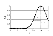
図3A〜図3Dに、転写パターン、目標パターンを形成するために使用するレチクルのパターンとして二次元矩形パターンを用い、照明はクロスポール照明を適用した例を示す。照明の二次元的分布は図3Aに示され、強度分布は断面図として図3Bに示されている。図3Bにおいて、横軸が図3Aで示される照明の半径方向の位置(r)、縦軸が強度である。ここでの強度分布はほぼガウス関数となっている。照明を記述するパラメータとしては強度分布の中心位置a、強度分布の幅b、開口角(横)Ψ1、開口角(縦)Ψ2が用いられている。 3A to 3D show examples in which a two-dimensional rectangular pattern is used as a reticle pattern used to form a transfer pattern and a target pattern, and cross pole illumination is applied as illumination. The two-dimensional distribution of illumination is shown in FIG. 3A, and the intensity distribution is shown in FIG. 3B as a cross-sectional view. In FIG. 3B, the horizontal axis represents the radial position (r) of the illumination shown in FIG. 3A, and the vertical axis represents the intensity. The intensity distribution here is almost a Gaussian function. As parameters for describing illumination, the center position a of the intensity distribution, the width b of the intensity distribution, the opening angle (horizontal) Ψ1, and the opening angle (vertical) Ψ2 are used.
図3Cの左側は、現状の第1照明条件による転写パターン(第1パターン)であり、それを再現する仮想の第3照明条件は、図3Aに示されるように、a=0.8、b=0.2、Ψ1=60、Ψ2=60である。図3Cの右側は目標パターンであり、図3Dはそれを再現する仮想の第2照明条件である。目標パターンは現状の転写パターンに対し、パターン中心部の寸法を4nm、6nm太くし、他の寸法を維持したパターンとなっている。目標パターンを再現する仮想の第2照明条件は、図3Dに示されるように、a=0.92、b=0.14、Ψ1=94、Ψ2=77である。いずれも数学的モデルを用いて算出されたものである。 The left side of FIG. 3C is a transfer pattern (first pattern) based on the current first illumination condition. The virtual third illumination condition for reproducing the pattern is a = 0.8, b = 0 as shown in FIG. 3A. .2, Ψ1 = 60, Ψ2 = 60. The right side of FIG. 3C is a target pattern, and FIG. 3D is a virtual second illumination condition for reproducing it. The target pattern is a pattern in which the dimensions at the center of the pattern are 4 nm and 6 nm thicker than the current transfer pattern, and other dimensions are maintained. As shown in FIG. 3D, virtual second illumination conditions for reproducing the target pattern are a = 0.92, b = 0.14, ψ1 = 94, and ψ2 = 77. Both are calculated using a mathematical model.
この二つの照明条件の差分Δa、Δb、ΔΨ1、ΔΨ2は、以下のとおりである。
Δa=0.92-0.80=0.12
Δb=0.14-0.20=-0.06
ΔΨ1=94-60=34
ΔΨ2=77-60=17
これらの差分を現状の第1照明条件に加えることにより、目標パターンを基板に転写できる第4照明条件を決定することができる。
Differences Δa, Δb, ΔΨ1, and ΔΨ2 between the two illumination conditions are as follows.
Δa = 0.92-0.80 = 0.12
Δb = 0.14-0.20 = -0.06
ΔΨ1 = 94-60 = 34
ΔΨ2 = 77-60 = 17
By adding these differences to the current first illumination condition, it is possible to determine the fourth illumination condition that can transfer the target pattern to the substrate.
現状の転写パターン及び目標パターンを再現する二つの仮想の照明条件はbitmapでも表現されるので、bitmapでの引き算も可能である。但し、この場合は引き算後、bitmapのある場所に負の値が発生する可能性がある。そして、引き算の結果を現在の第1照明条件に加えた後、その場所が負の値になる可能性が更に存在する。負の値は現実においてはゼロにする等の処理が必要で、誤差の要因となる。一方、現状の転写パターン及び目標パターンを再現する二つの仮想の照明条件が数値(パラメータ)で表現される場合、その数値は照明全体を表現しているので、現在の第1照明条件に差分を加えた時に負になる可能性は低い。 The two virtual illumination conditions that reproduce the current transfer pattern and target pattern are also expressed in bitmap, so subtraction in bitmap is also possible. However, in this case, after subtraction, there is a possibility that a negative value will occur at the place where the bitmap is located. Then, after adding the result of the subtraction to the current first lighting condition, there is a possibility that the location becomes a negative value. Negative values actually require processing such as zeroing, which causes errors. On the other hand, when the two virtual illumination conditions for reproducing the current transfer pattern and the target pattern are expressed by numerical values (parameters), the numerical value expresses the entire illumination. When added, it is unlikely to be negative.
ここでは転写パターンの輪郭を求める数学的モデルとしてレジスト計算を用いた。しかし、評価点が密集した直線パターンのように、光学計算とレジスト計算との結果に相違がほとんどない場合は、計算時間の短縮のため光学像計算を用いても良い。 Here, resist calculation is used as a mathematical model for obtaining the contour of the transfer pattern. However, when there is almost no difference between the results of the optical calculation and the resist calculation as in a straight line pattern with dense evaluation points, an optical image calculation may be used to shorten the calculation time.
[実施例2]
実施例1では、目標パターンを1種類のフォーカス条件でのパターンに設定している。これらは通常、ベストフォーカスのもとでの目標パターンである。しかし、ベストフォーカスを前提に目標パターンを再現する照明条件は、デフォーカスでは大きく目標パターンからずれる可能性がある。そのため、本実施例では目標パターンの輪郭とのずれが許容範囲内に収まるデフォーカス量の範囲が広い照明条件を探索する。図4では実線で示される目標転写パターンのグラフの上下近傍に目標パターンからある寸法許容内のグラフ(一点鎖線)が記述されているが、目標パターンがこの一点鎖線で示される範囲内に収まる照明条件を探索する。なお、図4には、現状の転写パターンが点線で示されている。
[Example 2]
In the first embodiment, the target pattern is set to a pattern under one type of focus condition. These are usually target patterns under best focus. However, the illumination conditions for reproducing the target pattern on the premise of the best focus may greatly deviate from the target pattern in defocusing. For this reason, in the present embodiment, an illumination condition that has a wide defocus amount range within which the deviation from the contour of the target pattern falls within the allowable range is searched. In FIG. 4, a graph within a certain dimension tolerance (one-dot chain line) from the target pattern is described in the vicinity of the upper and lower sides of the target transfer pattern graph indicated by the solid line. Search for conditions. In FIG. 4, the current transfer pattern is indicated by a dotted line.
デフォーカス量の範囲が広い照明条件を探索する方法において、最適化手法にて探索中の各照明条件について転写パターンを算出し、各評価点における目標寸法値(図4中に太い実線)からの差のrmsを計算する。そしてrmsのデフォーカス特性を算出し、グラフ化し、rmsが所定の値より小さいデフォーカス量の範囲(DOF)を算出し、算出されたDOFの値が最大になるように照明条件を最適化する。ベストフォーカスでの寸法値のみを目標とした最適化結果とデフォーカスを考慮した最適化結果を図5に示す。照明aは、ベストフォーカスではrmsは小さく良好であるが、デフォーカスと共にrmsが増大する。それに対し、照明bは、ベストフォーカスでのrmsは照明aよりも大きいが、デフォーカスしてもrmsの増加が緩やかである。 In a method for searching for illumination conditions with a wide range of defocus amounts, a transfer pattern is calculated for each illumination condition being searched by the optimization method, and a target dimension value at each evaluation point (thick solid line in FIG. 4) is calculated. Calculate the rms of the difference. The rms defocus characteristic is calculated and graphed, and the defocus amount range (DOF) where rms is smaller than a predetermined value is calculated, and the illumination conditions are optimized so that the calculated DOF value is maximized. . FIG. 5 shows an optimization result targeting only the dimension value at the best focus and an optimization result considering defocus. The illumination a is good with a small rms at the best focus, but the rms increases with the defocus. On the other hand, the rms at the best focus of the illumination b is larger than that of the illumination a, but the rms increases slowly even after defocusing.
照明a及び照明bのいずれを選択するかは、デバイスの製造プロセスにおいて、狭い製造マージンであるが高精度を目的とするか、広い製造マージンを必要とするかで決定される。通常、製造マージンの広いことの方が重要であり、したがって、デフォーカス範囲が広い照明bが選択されることが多い。 Whether to select the illumination a or the illumination b is determined in the device manufacturing process depending on whether a narrow manufacturing margin is intended for high accuracy or a wide manufacturing margin is required. Usually, it is more important that the manufacturing margin is wide, and therefore the illumination b having a wide defocus range is often selected.
[実施例3]
実施例1では、目標とする転写パターンとして1種類のフォーカス条件でのパターニング結果を対象とした。しかし、本実施例では、ある目標とする転写パターンに対し、互いに異なる複数のフォーカス条件でのパターニング結果を参照して、目標パターンを実現する照明条件を決定する。図6では、OPE評価パターンでベストフォーカス条件と60nmデフォーカス条件でのパターニング結果を対象にしている。この二つの条件で、現状の転写パターンを再現する照明条件での転写結果、目標パターンを再現する照明条件に対応する転写結果が各々二つずつ存在し、これらの転写結果を基に照明条件の最適化を行う。
[Example 3]
In Example 1, the patterning result under one focus condition was targeted as a target transfer pattern. However, in this embodiment, an illumination condition for realizing a target pattern is determined with reference to patterning results under a plurality of different focus conditions for a certain target transfer pattern. In FIG. 6, the OPE evaluation pattern covers the patterning results under the best focus condition and 60 nm defocus condition. Under these two conditions, there are two transfer results each corresponding to the illumination condition that reproduces the current transfer pattern, and two illumination results that correspond to the illumination condition that reproduces the target pattern. Perform optimization.
図7は二次元パターンでのベストフォーカスと60nmデフォーカスでの転写結果を対象にして決定した照明条件による転写パターンを示している。二次元パターンではベストフォーカスとデフォーカスの寸法差が目視で判断しにくいので、図7中にその寸法差を記述している。 FIG. 7 shows a transfer pattern according to illumination conditions determined for the best focus in a two-dimensional pattern and the transfer result at 60 nm defocus. In the two-dimensional pattern, the dimensional difference between the best focus and the defocus is difficult to visually determine, so the dimensional difference is described in FIG.
[実施例4]
次に実施例1と同様な概念の手法をOPE評価で行った場合を説明する。まず、各評価点に対し、目標パターンの寸法Li ( i=1、 ---、n)と現状の転写パターン(第1パターン)の寸法Miとの差分Δiを算出する。図8A中ではΔiを棒線で示している。
[Example 4]
Next, the case where the method of the concept similar to Example 1 is performed by OPE evaluation is demonstrated. First, for each evaluation point, a difference Δi between a target pattern dimension Li (i = 1, ---, n) and a current transfer pattern (first pattern) dimension Mi is calculated. In FIG. 8A, Δi is indicated by a bar.
次に、現在用いている第1照明条件Aで転写される仮想の転写パターン(第2パターン)をレジスト計算し、各評価点の寸法をNiとする。Niはレジスト計算の誤差、照明形状の数値定義と実際の露光装置の設定とのズレ等によりMiとは若干異なる値となる。次にPi=Ni+Δiを算出する。Pi、Niは図8Bに記述されている。図8B中のΔiに相当する棒線の長さは、図8A中のΔiに相当する棒線の長さと同じである。 Next, a virtual transfer pattern (second pattern) transferred under the currently used first illumination condition A is resist-calculated, and the dimension of each evaluation point is Ni. Ni is slightly different from Mi due to errors in resist calculation, deviation between the numerical definition of the illumination shape and the actual exposure apparatus settings. Next, Pi = Ni + Δi is calculated. Pi and Ni are described in FIG. 8B. The length of the bar corresponding to Δi in FIG. 8B is the same as the length of the bar corresponding to Δi in FIG. 8A.
そして、このPiからなる第3パターンを仮想の目標パターンとして上述の数学的モデルを適用し、仮想の目標パターンを再現する仮想の第5照明条件Bを得る。仮想の目標パターンの寸法Piは目標パターンの寸法Liとは異なる。それは現実のパターニングとシミュレーション内で発生するレジスト計算の誤差、照明形状の数値定義と実際の露光装置の設定とのズレ等から起因するものである。仮想の目標パターンPiを再現するために最適化された第5照明条件Bは、それを実際に適用する時、上記の誤差をキャンセルし、正しい結果を導く。 Then, the above-described mathematical model is applied using the third pattern of Pi as a virtual target pattern to obtain a virtual fifth illumination condition B that reproduces the virtual target pattern. The dimension Pi of the virtual target pattern is different from the dimension Li of the target pattern. This is caused by an actual patterning and a resist calculation error generated in the simulation, a deviation between the numerical definition of the illumination shape and the actual exposure apparatus setting, and the like. The fifth illumination condition B optimized to reproduce the virtual target pattern Pi cancels the above error when it is actually applied, and leads to a correct result.
仮想の目標パターン(第3パターン)を実現する第5照明条件Bを決定するフローチャートを図8Cに示す。ステップS21〜ステップS24は、図1CにおけるステップS11〜ステップS14と同一のステップであるので、説明を省略する。 FIG. 8C shows a flowchart for determining the fifth illumination condition B for realizing the virtual target pattern (third pattern). Steps S21 to S24 are the same as steps S11 to S14 in FIG.
ステップS25で、コンピュータは、複数の評価点において、目標パターンの寸法Liと現状の転写パターン(第1パターン)の寸法Miとの差分Δi=Li−Miを算出する。ステップS26で、コンピュータは、レジスト計算を行って、現状の第1照明条件Aで転写される仮想の転写パターン(第2パターン)の寸法Niを算出する。ステップS27で、コンピュータは、仮想の転写パターン(第2パターン)の寸法Niに差分Δiを加え、Ni+Δi=Piを算出する。Piは、仮想の目標パターン(第3パターン)の寸法を表している。 In step S25, the computer calculates a difference Δi = Li−Mi between the dimension Li of the target pattern and the dimension Mi of the current transfer pattern (first pattern) at a plurality of evaluation points. In step S <b> 26, the computer performs registration calculation to calculate a dimension Ni of a virtual transfer pattern (second pattern) transferred under the current first illumination condition A. In step S27, the computer adds the difference Δi to the dimension Ni of the virtual transfer pattern (second pattern), and calculates Ni + Δi = Pi. Pi represents the dimension of the virtual target pattern (third pattern).
ステップS28で、コンピュータは、その寸法がPiである仮想の目標転写パターン(第3パターン)を再現する第5照明条件Bを、数学的モデルを用いて算出する。ステップS26は仮想の第2パターンを算出する第2算出工程であり、ステップS28は仮想の第5照明条件を算出する第3算出工程である。数学的モデルとして、例えば遺伝的アルゴリズム、モンテカルロアルゴリズム等を含むモデルが使用されうる。ステップS29で、コンピュータは、第5照明条件Bを目標パターンを基板に転写する照明条件として決定する。 In step S28, the computer calculates a fifth illumination condition B that reproduces a virtual target transfer pattern (third pattern) whose dimension is Pi using a mathematical model. Step S26 is a second calculation step for calculating a virtual second pattern, and step S28 is a third calculation step for calculating a virtual fifth illumination condition. As the mathematical model, for example, a model including a genetic algorithm, a Monte Carlo algorithm, or the like can be used. In step S29, the computer determines the fifth illumination condition B as an illumination condition for transferring the target pattern to the substrate.
ステップS22からS29に至るステップの処理を実行するプログラムをコンピュータの記憶媒体に格納することができる。そうすれば、ステップS22からS29に至る目標パターンを基板に転写する照明条件を決定するための処理をコンピュータに実行させることができる。また、コンピュータが、当該プログラムを記録した記録媒体から当該プログラムコードを読み取ることにより上記照明条件を決定するための処理を実行することができる。 A program for executing the processing of the steps from S22 to S29 can be stored in a computer storage medium. Then, it is possible to cause the computer to execute processing for determining the illumination condition for transferring the target pattern from step S22 to S29 onto the substrate. Further, the computer can execute the process for determining the illumination condition by reading the program code from the recording medium on which the program is recorded.
本実施例において、実施例2及び実施例3で説明した、目標とする転写パターンがある寸法許容量に収まるデフォーカス量の範囲が広い照明条件を探索する方法、一つの転写パターンに対し複数のフォーカス条件における結果を対照とする方法が同様に適用され得る。 In this embodiment, the method for searching for illumination conditions having a wide range of defocus amounts within a certain dimension allowable amount described in the second and third embodiments, and a plurality of transfer patterns for one transfer pattern. A method that contrasts results in focus conditions can be applied as well.
[実施例5]
実施例2〜4では、目標パターンがある寸法許容量に収まるデフォーカス量の範囲が広い照明を探索する。本実施例では、露光量とフォーカスとの双方における許容範囲(ウインドウと呼ぶ)が広い照明条件を探索する。方法としては図9に示すように、露光量とフォーカスとの二次元空間において目標寸法からの誤差が許容範囲に収まる領域を算出し、その面積が最大になるように照明条件を最適化する。また、本実施例の応用例として、寸法誤差が許容範囲に収まる露光量の範囲が広い照明条件を探索してもよい。さらに、実施例3では、一つの転写パターンに対し複数のフォーカス条件での結果を参照して最適の照明条件を決定した。しかし、複数のフォーカス条件ではなく複数の露光量での結果を参照して照明条件を決定することもできる。
[Example 5]
In the second to fourth embodiments, an illumination having a wide defocus amount range within which a target pattern falls within a certain dimension allowable amount is searched. In this embodiment, an illumination condition having a wide allowable range (called a window) in both the exposure amount and the focus is searched. As a method, as shown in FIG. 9, a region where an error from a target dimension is within an allowable range in a two-dimensional space between an exposure amount and a focus is calculated, and an illumination condition is optimized so that the area is maximized. Further, as an application example of the present embodiment, an illumination condition having a wide exposure range in which a dimensional error is within an allowable range may be searched. Furthermore, in Example 3, the optimum illumination condition was determined with reference to the results under a plurality of focus conditions for one transfer pattern. However, it is also possible to determine the illumination condition by referring to the results at a plurality of exposure amounts instead of the plurality of focus conditions.
次に、半導体集積回路素子、液晶表示素子等のデバイス製造方法を例示的に説明する。デバイスは、上述の決定方法を用いて決定された照明条件を用いて基板を露光する露光工程と、露光工程で露光された基板を現像する現像工程と、現像工程で現像された基板を加工する他の周知の工程とを経ることによって製造される。他の周知の工程は、エッチング、レジスト剥離、ダイシング、ボンディング、パッケージング工程などである。 Next, device manufacturing methods such as semiconductor integrated circuit elements and liquid crystal display elements will be exemplarily described. The device exposes the substrate using the illumination condition determined using the determination method described above, develops the substrate exposed in the exposure step, and processes the substrate developed in the development step It is manufactured through other known processes. Other known processes are etching, resist stripping, dicing, bonding, packaging processes, and the like.
Li:目標パターンの寸法
Mi:転写パターンの寸法
Ni:転写パターンを再現する照明で形成される仮想の転写パターンの寸法
Pi:目標パターンを再現する照明で形成される仮想の転写パターンの寸法
Li: Target pattern dimensions
Mi: Transfer pattern dimensions
Ni: Dimensions of the virtual transfer pattern formed by illumination that reproduces the transfer pattern
Pi: Dimension of the virtual transfer pattern formed by illumination that reproduces the target pattern
Claims (10)
前記レチクルを用いて基板に形成するべき目標パターンを設定する設定工程と、
前記レチクルと第1照明条件を用いる露光を経て基板に転写された第1パターンのデータを取得する取得工程と、
照明条件と当該照明条件を用いて基板に転写される仮想のパターンとの関係を規定する数学的モデルを用いて、前記レチクルを用いて前記目標パターンを基板に転写させる仮想の第2照明条件と、前記レチクルを用いて前記第1パターンを基板に転写させる仮想の第3照明条件とを算出する算出工程と、
前記算出された第2照明条件と第3照明条件との差分を前記第1照明条件に加えた第4照明条件を、前記レチクルを用いて前記目標パターンを基板に転写する照明条件として決定する決定工程と、
を含むことを特徴とする決定方法。 A method for determining an illumination condition of the reticle in a lithography process for patterning the substrate by transferring the pattern of the reticle to the substrate by an exposure apparatus,
A setting step for setting a target pattern to be formed on the substrate using the reticle;
An acquisition step of acquiring data of the first pattern transferred to the substrate through exposure using the reticle and the first illumination condition;
A second virtual illumination condition for transferring the target pattern to the substrate using the reticle, using a mathematical model that defines a relationship between the illumination condition and a virtual pattern transferred to the substrate using the illumination condition; Calculating a virtual third illumination condition for transferring the first pattern to the substrate using the reticle;
Determination to determine a fourth illumination condition obtained by adding a difference between the calculated second illumination condition and the third illumination condition to the first illumination condition as an illumination condition for transferring the target pattern to the substrate using the reticle. Process,
A determination method characterized by comprising:
前記レチクルを用いて基板に形成するべき目標パターンを設定する設定工程と、
前記レチクルと第1照明条件を用いる露光を経て基板に転写された第1パターンのデータを取得する取得工程と、
照明条件と当該照明条件を用いて基板に転写される仮想のパターンとの関係を規定する数学的モデルを用いて、前記レチクルと前記第1照明条件を用いる露光を経て基板に転写される仮想の第2パターンを算出する第2算出工程と、
前記レチクルを用いる露光を経て、前記目標パターンと前記第1パターンとの差分を前記算出された第2パターンに加えた仮想の第3パターンを基板に転写させる仮想の第5照明条件を、前記モデルを用いて算出する第3算出工程と、
前記算出された第5照明条件を、前記レチクルを用いて前記目標パターンを基板に転写する照明条件として決定する決定工程と、
を含むことを特徴とする決定方法。 A method for determining an illumination condition of the reticle in a lithography process for patterning the substrate by transferring the pattern of the reticle to the substrate by an exposure apparatus,
A setting step for setting a target pattern to be formed on the substrate using the reticle;
An acquisition step of acquiring data of the first pattern transferred to the substrate through exposure using the reticle and the first illumination condition;
Using a mathematical model that defines the relationship between the illumination conditions and a virtual pattern transferred to the substrate using the illumination conditions, a virtual model transferred to the substrate through exposure using the reticle and the first illumination condition A second calculation step of calculating a second pattern;
A virtual fifth illumination condition for transferring a virtual third pattern, which is obtained by adding the difference between the target pattern and the first pattern to the calculated second pattern to the substrate through the exposure using the reticle, is the model. A third calculation step of calculating using
A determination step of determining the calculated fifth illumination condition as an illumination condition for transferring the target pattern to a substrate using the reticle;
A determination method characterized by comprising:
前記レチクルを用いて基板に形成するべき目標パターンを設定する設定ステップと、
前記レチクルと第1照明条件を用いる露光を経て基板に転写された第1パターンのデータを取得する取得ステップと、
照明条件と当該照明条件を用いて基板に転写される仮想のパターンとの関係を規定する数学的モデルを用いて、前記レチクルを用いて前記目標パターンを基板に転写させる仮想の第2照明条件と、前記レチクルを用いて前記第1パターンを基板に転写させる仮想の第3照明条件とを算出する算出ステップと、
前記算出された第2照明条件と第3照明条件との差分を前記第1照明条件に加えた第4照明条件を、前記レチクルを用いて前記目標パターンを基板に転写する照明条件として決定する決定ステップと、
を含むことを特徴とするプログラム。 A program for causing a computer to execute a process for determining an illumination condition of the reticle in a lithography process of patterning the substrate by transferring the pattern of the reticle to the substrate by an exposure apparatus,
A setting step for setting a target pattern to be formed on the substrate using the reticle;
An acquisition step of acquiring data of a first pattern transferred to the substrate through exposure using the reticle and the first illumination condition;
A second virtual illumination condition for transferring the target pattern to the substrate using the reticle, using a mathematical model that defines a relationship between the illumination condition and a virtual pattern transferred to the substrate using the illumination condition; Calculating a virtual third illumination condition for transferring the first pattern to the substrate using the reticle;
Determination to determine a fourth illumination condition obtained by adding a difference between the calculated second illumination condition and the third illumination condition to the first illumination condition as an illumination condition for transferring the target pattern to the substrate using the reticle. Steps,
The program characterized by including.
前記レチクルを用いて基板に形成するべき目標パターンを設定する設定ステップと、
前記レチクルと第1照明条件を用いる露光を経て基板に転写された第1パターンのデータを取得する取得ステップと、
照明条件と当該照明条件を用いて基板に転写される仮想のパターンとの関係を規定する数学的モデルを用いて、前記レチクルと前記第1照明条件を用いる露光を経て基板に転写される仮想の第2パターンを算出する第2算出ステップと、
前記レチクルを用いる露光を経て、前記目標パターンと前記第1パターンとの差分を前記算出された第2パターンに加えた仮想の第3パターンを基板に転写させる仮想の第5照明条件を、前記モデルを用いて算出する第3算出ステップと、
前記算出された第5照明条件を、前記レチクルを用いて前記目標パターンを基板に転写する照明条件として決定する決定ステップと、
を含むことを特徴とするプログラム。 A program for causing a computer to execute a process for determining an illumination condition of the reticle in a lithography process of patterning the substrate by transferring the pattern of the reticle to the substrate by an exposure apparatus,
A setting step for setting a target pattern to be formed on the substrate using the reticle;
An acquisition step of acquiring data of a first pattern transferred to the substrate through exposure using the reticle and the first illumination condition;
Using a mathematical model that defines the relationship between the illumination conditions and a virtual pattern transferred to the substrate using the illumination conditions, a virtual model transferred to the substrate through exposure using the reticle and the first illumination condition A second calculation step of calculating a second pattern;
A virtual fifth illumination condition for transferring a virtual third pattern, which is obtained by adding the difference between the target pattern and the first pattern to the calculated second pattern to the substrate through the exposure using the reticle, is the model. A third calculation step of calculating using
A determination step of determining the calculated fifth illumination condition as an illumination condition for transferring the target pattern to a substrate using the reticle;
The program characterized by including.
請求項1乃至請求項6のいずれか1項に記載の決定方法を用いて決定された照明条件を用いて基板を露光する露光方法。 An exposure method for exposing a substrate by transferring a reticle pattern to the substrate by an exposure apparatus,
An exposure method for exposing a substrate using illumination conditions determined using the determination method according to claim 1.
前記工程で露光された基板を現像する工程と、
を含むデバイス製造方法。 Exposing the substrate with the exposure method according to claim 9;
Developing the substrate exposed in the step;
A device manufacturing method including:
Priority Applications (2)
| Application Number | Priority Date | Filing Date | Title |
|---|---|---|---|
| JP2008278611A JP5215812B2 (en) | 2008-10-29 | 2008-10-29 | Illumination condition determination method, program, exposure method, and device manufacturing method |
| US12/607,015 US8049191B2 (en) | 2008-10-29 | 2009-10-27 | Method of transferring pattern of reticle, computer readable storage medium, and method of manufacturing device |
Applications Claiming Priority (1)
| Application Number | Priority Date | Filing Date | Title |
|---|---|---|---|
| JP2008278611A JP5215812B2 (en) | 2008-10-29 | 2008-10-29 | Illumination condition determination method, program, exposure method, and device manufacturing method |
Publications (3)
| Publication Number | Publication Date |
|---|---|
| JP2010109088A JP2010109088A (en) | 2010-05-13 |
| JP2010109088A5 JP2010109088A5 (en) | 2011-02-03 |
| JP5215812B2 true JP5215812B2 (en) | 2013-06-19 |
Family
ID=42116582
Family Applications (1)
| Application Number | Title | Priority Date | Filing Date |
|---|---|---|---|
| JP2008278611A Expired - Fee Related JP5215812B2 (en) | 2008-10-29 | 2008-10-29 | Illumination condition determination method, program, exposure method, and device manufacturing method |
Country Status (2)
| Country | Link |
|---|---|
| US (1) | US8049191B2 (en) |
| JP (1) | JP5215812B2 (en) |
Families Citing this family (4)
| Publication number | Priority date | Publication date | Assignee | Title |
|---|---|---|---|---|
| US8739079B2 (en) * | 2009-10-30 | 2014-05-27 | Canon Kabushiki Kaisha | Recording medium and determination method |
| JP5539148B2 (en) * | 2010-10-19 | 2014-07-02 | キヤノン株式会社 | Method and program for calculating resist pattern |
| KR20130006737A (en) | 2011-02-28 | 2013-01-18 | 삼성전자주식회사 | Methods of fabricating a semiconductor device |
| JP5835968B2 (en) * | 2011-07-05 | 2015-12-24 | キヤノン株式会社 | Determination method, program, and exposure method |
Family Cites Families (13)
| Publication number | Priority date | Publication date | Assignee | Title |
|---|---|---|---|---|
| US5680588A (en) * | 1995-06-06 | 1997-10-21 | International Business Machines Corporation | Method and system for optimizing illumination in an optical photolithography projection imaging system |
| US6774043B2 (en) * | 2000-04-12 | 2004-08-10 | Renesas Technology Corp. | Method of manufacturing semiconductor device |
| JP2002174890A (en) * | 2000-12-07 | 2002-06-21 | Hitachi Ltd | Method for producing semiconductor integrated circuit |
| JP2002175969A (en) * | 2000-12-07 | 2002-06-21 | Hitachi Ltd | Method of testing pattern and data processing system |
| JP2002319534A (en) * | 2001-04-24 | 2002-10-31 | Nikon Corp | Electron beam exposure method, electron beam aligner, electron beam exposure mask, and manufacturing method of device |
| CN100446179C (en) * | 2002-12-10 | 2008-12-24 | 株式会社尼康 | Exposure apparatus and device manufacturing method |
| JP4192618B2 (en) * | 2003-02-17 | 2008-12-10 | ソニー株式会社 | Mask correction method |
| KR100652403B1 (en) * | 2005-02-26 | 2006-12-01 | 삼성전자주식회사 | Multiple exposure system and method of multiple exposure using the same |
| JP4336671B2 (en) * | 2005-07-15 | 2009-09-30 | キヤノン株式会社 | A program for causing a computer to determine exposure parameters, a determination method for determining exposure parameters, an exposure method, and a device manufacturing method. |
| JP4697426B2 (en) * | 2005-11-18 | 2011-06-08 | 株式会社ニコン | Light intensity distribution evaluation method, illumination optical apparatus and adjustment method thereof, exposure apparatus, and exposure method |
| JP4989279B2 (en) * | 2007-04-05 | 2012-08-01 | 株式会社東芝 | Parameter value adjusting method, semiconductor device manufacturing method, and program |
| JP2009302206A (en) * | 2008-06-11 | 2009-12-24 | Canon Inc | Method of determining exposure parameter, program for determining exposure parameter, exposure method, and device manufacturing method |
| US20100290020A1 (en) * | 2009-05-15 | 2010-11-18 | Shinichi Mori | Optical apparatus, exposure apparatus, exposure method, and method for producing device |
-
2008
- 2008-10-29 JP JP2008278611A patent/JP5215812B2/en not_active Expired - Fee Related
-
2009
- 2009-10-27 US US12/607,015 patent/US8049191B2/en not_active Expired - Fee Related
Also Published As
| Publication number | Publication date |
|---|---|
| JP2010109088A (en) | 2010-05-13 |
| US20100102255A1 (en) | 2010-04-29 |
| US8049191B2 (en) | 2011-11-01 |
Similar Documents
| Publication | Publication Date | Title |
|---|---|---|
| JP4351928B2 (en) | Mask data correction method, photomask manufacturing method, and mask data correction program | |
| KR100839972B1 (en) | Lithographic apparatus and device manufacturing method | |
| US8849008B2 (en) | Determining calibration parameters for a lithographic process | |
| US9442381B2 (en) | Method of operating a projection exposure tool for microlithography | |
| KR101711699B1 (en) | Mask pattern generating method, recording medium, and information processing apparatus | |
| KR101124919B1 (en) | Method of determining exposure parameter, exposure method, method of manufacturing device and recording medium | |
| KR20170141740A (en) | Measurement target design for tilted device design | |
| CN101258498A (en) | System and method for creating a focus-exposure model of a lithography process | |
| KR20170097133A (en) | Method and apparatus for using patterning device topography induced phase | |
| US20210149296A1 (en) | Reduction or elimination of pattern placement error in metrology measurements | |
| US7213226B2 (en) | Pattern dimension correction method and verification method using OPC, mask and semiconductor device fabricated by using the correction method, and system and software product for executing the correction method | |
| KR20130008662A (en) | Method of forming photomask layout | |
| US20170091921A1 (en) | Method for determining a position of a structure element on a mask and microscope for carrying out the method | |
| JP5215812B2 (en) | Illumination condition determination method, program, exposure method, and device manufacturing method | |
| US8230369B2 (en) | Simulation method and simulation program | |
| US20170315441A1 (en) | Method and apparatus for using patterning device topography induced phase | |
| US7207030B2 (en) | Method for improving a simulation model of photolithographic projection | |
| WO2016096338A1 (en) | Method and apparatus for using patterning device topography induced phase | |
| TWI621926B (en) | Lithographic method and apparatus, computer program, computer readable medium, computer apparatus, controller, and projection system for lithographic apparatus | |
| WO2016096346A1 (en) | Method and apparatus for using patterning device topography induced phase | |
| Flagello et al. | Understanding illumination effects for control of optical proximity effects (OPE) | |
| JP2012191018A (en) | Program and determination method | |
| JP2007317921A (en) | Lithography simulation method and program | |
| Renwick et al. | Characterizing a scanner illuminator for prediction of OPE effects | |
| TWI837432B (en) | Alignment method and associated alignment and lithographic apparatuses |
Legal Events
| Date | Code | Title | Description |
|---|---|---|---|
| A521 | Request for written amendment filed |
Free format text: JAPANESE INTERMEDIATE CODE: A523 Effective date: 20101210 |
|
| A621 | Written request for application examination |
Free format text: JAPANESE INTERMEDIATE CODE: A621 Effective date: 20101210 |
|
| A977 | Report on retrieval |
Free format text: JAPANESE INTERMEDIATE CODE: A971007 Effective date: 20120523 |
|
| A131 | Notification of reasons for refusal |
Free format text: JAPANESE INTERMEDIATE CODE: A131 Effective date: 20120601 |
|
| A521 | Request for written amendment filed |
Free format text: JAPANESE INTERMEDIATE CODE: A523 Effective date: 20120704 |
|
| TRDD | Decision of grant or rejection written | ||
| A01 | Written decision to grant a patent or to grant a registration (utility model) |
Free format text: JAPANESE INTERMEDIATE CODE: A01 Effective date: 20130201 |
|
| A61 | First payment of annual fees (during grant procedure) |
Free format text: JAPANESE INTERMEDIATE CODE: A61 Effective date: 20130301 |
|
| R151 | Written notification of patent or utility model registration |
Ref document number: 5215812 Country of ref document: JP Free format text: JAPANESE INTERMEDIATE CODE: R151 |
|
| FPAY | Renewal fee payment (event date is renewal date of database) |
Free format text: PAYMENT UNTIL: 20160308 Year of fee payment: 3 |
|
| LAPS | Cancellation because of no payment of annual fees |