JP5215425B2 - Ultrasonic diagnostic equipment - Google Patents
Ultrasonic diagnostic equipment Download PDFInfo
- Publication number
- JP5215425B2 JP5215425B2 JP2011051888A JP2011051888A JP5215425B2 JP 5215425 B2 JP5215425 B2 JP 5215425B2 JP 2011051888 A JP2011051888 A JP 2011051888A JP 2011051888 A JP2011051888 A JP 2011051888A JP 5215425 B2 JP5215425 B2 JP 5215425B2
- Authority
- JP
- Japan
- Prior art keywords
- ultrasonic
- image
- temperature
- depth
- diagnostic apparatus
- Prior art date
- Legal status (The legal status is an assumption and is not a legal conclusion. Google has not performed a legal analysis and makes no representation as to the accuracy of the status listed.)
- Active
Links
- 230000005540 biological transmission Effects 0.000 claims description 147
- 239000000523 sample Substances 0.000 claims description 111
- 238000012545 processing Methods 0.000 claims description 87
- 238000009529 body temperature measurement Methods 0.000 claims description 78
- 238000002604 ultrasonography Methods 0.000 claims description 34
- 230000003247 decreasing effect Effects 0.000 claims description 26
- 230000007423 decrease Effects 0.000 claims description 22
- 230000002194 synthesizing effect Effects 0.000 claims description 7
- 238000002592 echocardiography Methods 0.000 claims description 5
- 238000003745 diagnosis Methods 0.000 claims description 2
- 238000004891 communication Methods 0.000 description 37
- 238000013329 compounding Methods 0.000 description 28
- 150000001875 compounds Chemical class 0.000 description 27
- 238000000034 method Methods 0.000 description 19
- 238000010586 diagram Methods 0.000 description 12
- 238000006243 chemical reaction Methods 0.000 description 11
- 230000008569 process Effects 0.000 description 9
- 238000013500 data storage Methods 0.000 description 7
- 238000005259 measurement Methods 0.000 description 6
- 230000015556 catabolic process Effects 0.000 description 4
- 238000006731 degradation reaction Methods 0.000 description 4
- 230000006870 function Effects 0.000 description 4
- 230000020169 heat generation Effects 0.000 description 4
- 230000009467 reduction Effects 0.000 description 4
- 230000004044 response Effects 0.000 description 4
- 230000015572 biosynthetic process Effects 0.000 description 2
- 230000006866 deterioration Effects 0.000 description 2
- 230000000694 effects Effects 0.000 description 2
- HFGPZNIAWCZYJU-UHFFFAOYSA-N lead zirconate titanate Chemical compound [O-2].[O-2].[O-2].[O-2].[O-2].[Ti+4].[Zr+4].[Pb+2] HFGPZNIAWCZYJU-UHFFFAOYSA-N 0.000 description 2
- 229910052451 lead zirconate titanate Inorganic materials 0.000 description 2
- 230000010363 phase shift Effects 0.000 description 2
- 238000005070 sampling Methods 0.000 description 2
- 238000003786 synthesis reaction Methods 0.000 description 2
- 239000002033 PVDF binder Substances 0.000 description 1
- 230000003321 amplification Effects 0.000 description 1
- 230000001934 delay Effects 0.000 description 1
- 238000001514 detection method Methods 0.000 description 1
- 238000003384 imaging method Methods 0.000 description 1
- 239000000463 material Substances 0.000 description 1
- 238000012986 modification Methods 0.000 description 1
- 230000004048 modification Effects 0.000 description 1
- 238000003199 nucleic acid amplification method Methods 0.000 description 1
- 230000002265 prevention Effects 0.000 description 1
- 230000001902 propagating effect Effects 0.000 description 1
- 230000035945 sensitivity Effects 0.000 description 1
Images


Description
本発明は、超音波診断装置に関し、特に、超音波プローブの発熱を抑制することができる超音波診断装置に関する。 The present invention relates to an ultrasonic diagnostic apparatus, and more particularly to an ultrasonic diagnostic apparatus that can suppress heat generation of an ultrasonic probe.
医療分野において、超音波画像を利用した超音波診断装置が実用化されている。
一般に、この種の超音波診断装置は、超音波プローブ(超音波探触子 以下、プローブとする)と、診断装置本体とを有しており、プローブから被検体に向けて超音波を送信し、被検体からの超音波エコーをプローブで受信して、その受信信号を診断装置本体で電気的に処理することにより超音波画像が生成される。
In the medical field, an ultrasonic diagnostic apparatus using an ultrasonic image has been put into practical use.
In general, this type of ultrasonic diagnostic apparatus includes an ultrasonic probe (hereinafter referred to as a probe) and a diagnostic apparatus main body, and transmits ultrasonic waves from the probe toward a subject. The ultrasonic echo from the subject is received by the probe, and the received signal is electrically processed by the diagnostic apparatus body to generate an ultrasonic image.
このような超音波診断装置において、超音波画像の画質を劣化させる要因として、いわゆるスペックル(スペックルノイズ/スペックルパターン)が知られている。スペックルとは、被検体内に存在する超音波の波長より小さな無数の散乱源によって、散乱波が生じ、この散乱波が互いに干渉することによって生じる、白い点状のノイズである。 In such an ultrasonic diagnostic apparatus, so-called speckle (speckle noise / speckle pattern) is known as a factor that degrades the image quality of an ultrasonic image. Speckle is white point-like noise that is generated when scattered waves are generated by innumerable scattering sources smaller than the wavelength of ultrasonic waves existing in the subject and the scattered waves interfere with each other.
超音波診断装置において、このようなスペックルを低減させる方法として、特許文献1や特許文献2に開示されるような、空間コンパウンドが知られている。
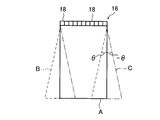
空間コンパウンドとは、図11に概念的に示すように、圧電素子ユニット100から、被検体に対して方向(走査角度)が互いに異なる複数種類(複数方向)の超音波の送受信を行い、この複数種類の送受信によって得られた超音波画像を合成することにより、1つの合成超音波画像を生成する技術である。
As a method for reducing such speckle in an ultrasonic diagnostic apparatus, a spatial compound as disclosed in Patent Literature 1 and Patent Literature 2 is known.
As conceptually shown in FIG. 11, the spatial compound transmits and receives a plurality of types (multiple directions) of ultrasonic waves having different directions (scanning angles) from the
具体的には、図11に示す例においては、通常の超音波画像の生成と同様の超音波の送受信(通常の送受信)、通常に対して角度をθ傾けた方向の超音波の送受信、および、通常に対して角度を−θ傾けた方向の超音波の送受信の、3種類(3方向)の超音波の送受信を行なう。
この通常の送受信で得られた超音波画像A(実線)、角度をθ傾けた送受信で得られた超音波画像B(破線)、および、角度を−θ傾けた送受信で得られた超音波画像C(一点鎖線)を合成することで、実線で示す超音波画像Aの領域の合成超音波画像を生成する。
Specifically, in the example shown in FIG. 11, transmission / reception of ultrasonic waves (normal transmission / reception) similar to generation of a normal ultrasonic image, transmission / reception of ultrasonic waves in a direction inclined by θ with respect to normal, and Three types (three directions) of ultrasonic transmission / reception are performed, that is, transmission / reception of ultrasonic waves in a direction inclined by −θ with respect to a normal angle.
The ultrasonic image A (solid line) obtained by the normal transmission / reception, the ultrasonic image B (broken line) obtained by the transmission / reception with the angle inclined by θ, and the ultrasonic image obtained by the transmission / reception with the angle inclined by −θ. By combining C (one-dot chain line), a combined ultrasonic image of the region of the ultrasonic image A indicated by the solid line is generated.
ところで、このような超音波診断装置を構成するプローブは、被検体に超音波を送信し、かつ、被検体によって反射された超音波エコーを受信して、電気信号(受信信号)として出力する圧電素子ユニットを有する。
また、近年では、プローブは、圧電素子ユニットが出力した受信信号の増幅、A/D変換や処理、圧電素子ユニットにおける超音波の送受信のタイミングの切り換え、さらには、診断装置本体との無線通信によるコードレス化やノイズ低減等を行なうための、集積回路基板等を搭載する場合も有る。
By the way, a probe constituting such an ultrasonic diagnostic apparatus transmits an ultrasonic wave to a subject, receives an ultrasonic echo reflected by the subject, and outputs it as an electrical signal (received signal). It has an element unit.
Further, in recent years, the probe is based on amplification of received signals output from the piezoelectric element unit, A / D conversion and processing, switching of transmission / reception timing of ultrasonic waves in the piezoelectric element unit, and wireless communication with the diagnostic apparatus body. In some cases, an integrated circuit board or the like is mounted for cordless operation or noise reduction.
周知のように、圧電素子ユニットは、超音波の送受信を行なうことにより発熱する。また、圧電素子ユニットが送信する超音波の出力が高くなるほど、高画質な超音波画像が得られるが、その反面、圧電素子ユニットの発熱量も多くなる。
また、集積回路基板も、受信信号の処理等を行なうことによって発熱する。
As is well known, the piezoelectric element unit generates heat by transmitting and receiving ultrasonic waves. In addition, the higher the output of the ultrasonic wave transmitted by the piezoelectric element unit, the higher the quality of the ultrasonic image is obtained. On the other hand, the amount of heat generated by the piezoelectric element unit also increases.
Further, the integrated circuit board also generates heat by processing received signals and the like.
プローブが発熱すると、圧線素子ユニットの駆動が不安定になり、また、集積回路基板の各回路の動作も不安定になる。その結果、送信する超音波や、受信した超音波に対する出力信号が不安定になり、さらに、集積回路基板における信号処理も不安定になり、超音波画像の画質が低下してしまう。
そのため、高画質な超音波画像を安定して得るためには、超音波診断装置では、プローブ内部での温度上昇を、できるだけ抑制する必要がある。
When the probe generates heat, the driving of the pressure line element unit becomes unstable, and the operation of each circuit of the integrated circuit board becomes unstable. As a result, the transmitted ultrasonic wave and the output signal for the received ultrasonic wave become unstable, and further, the signal processing in the integrated circuit board becomes unstable, and the image quality of the ultrasonic image is degraded.
Therefore, in order to stably obtain a high-quality ultrasonic image, it is necessary for the ultrasonic diagnostic apparatus to suppress the temperature rise inside the probe as much as possible.
本発明の目的は、前記従来技術の問題点を解決することにあり、空間コンパウンドによる超音波画像(合成超音波画像)の生成を行なう際に、超音波プローブ内で温度上昇を抑制すると共に、温度上昇が生じても、超音波画像の画質劣化を最小限に抑えることができる超音波診断装置を提供することにある。 An object of the present invention is to solve the above-described problems of the prior art, and suppresses a temperature rise in an ultrasonic probe when generating an ultrasonic image (synthetic ultrasonic image) by a spatial compound, An object of the present invention is to provide an ultrasonic diagnostic apparatus capable of minimizing image quality degradation of an ultrasonic image even when the temperature rises.
前記目的を達成するために、本発明の超音波診断装置は、超音波を送信し、被検体によって反射された超音波エコーを受信して受信した超音波に応じた受信信号を出力する圧電素子ユニット、前記圧電素子ユニットによる超音波の送信を制御する送信制御手段、前記圧電素子ユニットが出力した受信信号の処理を行なう信号処理手段、および、所定位置の温度を測定する温度測定手段を有する超音波プローブと、前記超音波プローブの信号処理手段が処理した受信信号に応じた超音波画像を生成する診断装置本体とを有し、前記診断装置本体は、所定数の前記超音波画像を合成して1つの合成超音波画像を生成する機能を有し、また、前記超音波プローブは、前記診断装置本体が合成超音波画像の生成を行なうために、超音波の送受信方向が互いに異なる前記所定数と同数の複数種類の超音波の送受信を行なう機能を有し、かつ、前記超音波プローブは、前記診断装置本体が合成超音波画像の生成を行なう際には、前記温度測定手段による温度測定結果に応じて、前記診断装置本体が合成する超音波画像の所定深度よりも深い領域の音線数を減少するように、前記信号処理手段による受信信号の処理を調整し、さらに、前記診断装置本体は、前記所定深度以降で減少された音線は、周囲の音線を用いて補間して前記超音波画像を生成することを特徴とする超音波診断装置を提供する。 In order to achieve the above object, an ultrasonic diagnostic apparatus of the present invention transmits an ultrasonic wave, receives an ultrasonic echo reflected by a subject, and outputs a received signal corresponding to the received ultrasonic wave. A unit, a transmission control unit that controls transmission of ultrasonic waves by the piezoelectric element unit, a signal processing unit that processes a received signal output from the piezoelectric element unit, and a temperature measuring unit that measures a temperature at a predetermined position An ultrasonic probe and a diagnostic device main body that generates an ultrasonic image according to the received signal processed by the signal processing means of the ultrasonic probe, and the diagnostic device main body synthesizes a predetermined number of the ultrasonic images. A function of generating one synthesized ultrasound image, and the ultrasound probe has a transmission / reception direction of ultrasound so that the diagnostic apparatus body generates a synthesized ultrasound image. The ultrasonic probe has a function of transmitting and receiving a plurality of types of ultrasonic waves having the same number as the different predetermined number, and the ultrasonic probe has the temperature when the diagnostic apparatus body generates a synthetic ultrasonic image. In accordance with the temperature measurement result by the measurement means, adjust the processing of the received signal by the signal processing means so as to reduce the number of sound rays in a region deeper than a predetermined depth of the ultrasonic image synthesized by the diagnostic apparatus body, Furthermore, the diagnostic apparatus main body provides an ultrasonic diagnostic apparatus characterized in that the ultrasonic image is generated by interpolating sound rays reduced after the predetermined depth using surrounding sound rays.
このような本発明の超音波診断装置において、前記温度測定手段は、前記信号処理手段の温度を測定するのが好ましい。
また、温度の閾値として、温度T1と、この温度T1よりも高温の温度T2とが設定されており、さらに、前記音線数を減少する所定深度として、音線数を減少しない通常深度、深度が最も浅い短深度、および、前記通常深度と短深度との間の深度である中間深度が設定されているのが好ましい。
また、前記診断装置本体が合成超音波画像を生成する際には、前記超音波プローブは、前記温度測定手段による温度測定結果に応じて、この温度測定結果が前記温度T1未満である場合には、前記所定数の超音波画像の全てを前記通常深度とするのが好ましい。
In such an ultrasonic diagnostic apparatus of the present invention, it is preferable that the temperature measuring unit measures the temperature of the signal processing unit.
Further, a temperature T1 and a temperature T2 that is higher than the temperature T1 are set as temperature thresholds. Further, as the predetermined depth for reducing the number of sound rays, the normal depth and depth that do not reduce the number of sound rays Is set to a shallowest short depth and an intermediate depth that is a depth between the normal depth and the short depth.
In addition, when the diagnostic apparatus main body generates a synthetic ultrasonic image, the ultrasonic probe determines that the temperature measurement result is less than the temperature T1 according to the temperature measurement result by the temperature measurement unit. It is preferable that all of the predetermined number of ultrasonic images have the normal depth.
また、前記診断装置本体が合成超音波画像を生成する際には、前記超音波プローブは、前記温度測定手段による温度測定結果に応じて、この温度測定結果が前記温度T1以上温度T2未満の場合には、前記所定数の超音波画像のうちの2以上を、前記中間深度で音線数を減少し、この温度測定結果が前記温度T2以上の場合には、前記所定数の超音波送画像のうちの2以上を、前記短深度で音線数を減少するのが好ましい。
もしくは、前記診断装置本体が合成超音波画像を生成する際には、前記超音波プローブは、前記温度測定手段による温度測定結果に応じて、温度測定結果が前記温度T1以上温度T2未満の場合には、前記所定数の超音波送画像のうちの2以上を、前記中間深度で音線数を減少し、温度測定結果が前記温度T2以上の場合には、前記所定数の超音波送画像の少なくとも1つで、前記中間深度で音線数を減少し、他の少なくとも1つで、前記短深度で音線数を減少するのが好ましい。
また、前記診断装置本体が合成超音波画像を生成する際には、前記超音波プローブは、前記複数種類の超音波送受信のうちの1回で、前記合成超音波画像として出力する全域を包含する超音波画像が得られる主画像の超音波の送受信を行ない、かつ、この主画像の超音波の送受信で得られる超音波画像は、前記通常深度とするのが好ましい。
In addition, when the diagnostic apparatus main body generates a synthetic ultrasound image, the ultrasound probe determines that the temperature measurement result is not less than the temperature T1 and less than the temperature T2 according to the temperature measurement result by the temperature measurement means. Includes reducing the number of sound rays at two or more of the predetermined number of ultrasonic images at the intermediate depth, and when the temperature measurement result is equal to or higher than the temperature T2, the predetermined number of ultrasonic images. It is preferable to reduce the number of sound rays at the short depth for two or more of them.
Or when the said diagnostic apparatus main body produces | generates a synthetic | combination ultrasonic image, according to the temperature measurement result by the said temperature measurement means, the said ultrasonic probe is when temperature measurement result is more than the said temperature T1 and less than temperature T2. Decreases the number of sound rays at two or more of the predetermined number of ultrasonic transmission images at the intermediate depth, and if the temperature measurement result is equal to or higher than the temperature T2, the predetermined number of ultrasonic transmission images Preferably, at least one reduces the number of sound rays at the intermediate depth, and at least one other reduces the number of sound rays at the short depth.
In addition, when the diagnostic apparatus main body generates a synthetic ultrasound image, the ultrasound probe includes the entire region that is output as the synthesized ultrasound image once in the plurality of types of ultrasound transmission / reception. The ultrasonic image obtained by transmitting / receiving ultrasonic waves of the main image from which the ultrasonic image is obtained is preferably set to the normal depth.
また、前記診断装置本体が合成超音波画像を生成する際には、前記超音波プローブは、前記温度測定手段による温度測定結果に応じて、この温度測定結果が前記温度T1以上温度T2未満の場合には、前記所定数の超音波送画像のうちの2以上を、前記中間深度で音線数を減少し、温度測定結果が前記温度T2以上の場合には、前記所定数の超音波送画像のうちの2以上を、前記短深度で音線数を減少し、それ以外を全て前記中間深度で音線数を減少するのが好ましい。 In addition, when the diagnostic apparatus main body generates a synthetic ultrasound image, the ultrasound probe determines that the temperature measurement result is not less than the temperature T1 and less than the temperature T2 according to the temperature measurement result by the temperature measurement means. In the case where two or more of the predetermined number of ultrasonic transmission images are reduced in the number of sound rays at the intermediate depth and the temperature measurement result is equal to or higher than the temperature T2, the predetermined number of ultrasonic transmission images. It is preferable to reduce the number of sound rays at the short depth for two or more of them, and reduce the number of sound rays at the intermediate depth for all others.
また、前記超音波プローブは、時間的に連続する前記合成超音波画像において、最も近接する超音波画像の超音波送受信方向を等しくするのが好ましい。 Moreover, it is preferable that the ultrasonic probe equalizes the ultrasonic transmission / reception direction of the closest ultrasonic image in the temporally continuous synthesized ultrasonic image.
上記構成を有する本発明の超音波診断装置は、超音波の送受信方向が異なる複数の超音波画像を合成する空間コンパウンドを行なう際に、超音波プローブ内の温度上昇が生じたら、その温度上昇に応じて、合成される超音波画像の所定深度よりも深い領域で音線数を減少するように、超音波エコーの受信信号の処理を制御する。
そのため、本発明においては、空間コンパウンドを行なう際には、超音波プローブ内の温度に応じて、超音波プローブに搭載されて、受信信号を処理するAFEなどの集積回路の駆動時間を短縮できる。従って、超音波プローブ内で発熱が生じた際に、この温度上昇を迅速に抑制することができる。また、超音波プローブが発熱した際にも、発熱を抑制して、画質の劣化を最小限に抑えることができる。
従って、本発明の超音波診断装置によれば、空間コンパウンドによって、高画質な超音波画像を、安定して得ることができる。
The ultrasonic diagnostic apparatus of the present invention having the above-described configuration, when performing a spatial compound for synthesizing a plurality of ultrasonic images with different ultrasonic transmission / reception directions, if the temperature in the ultrasonic probe rises, the temperature rises. In response, the processing of the received signal of the ultrasonic echo is controlled so that the number of sound rays is reduced in a region deeper than a predetermined depth of the synthesized ultrasonic image.
Therefore, in the present invention, when performing spatial compounding, the driving time of an integrated circuit such as an AFE that is mounted on an ultrasonic probe and processes a received signal can be shortened according to the temperature in the ultrasonic probe. Therefore, when heat generation occurs in the ultrasonic probe, this temperature increase can be quickly suppressed. In addition, when the ultrasonic probe generates heat, the generation of heat can be suppressed and deterioration in image quality can be minimized.
Therefore, according to the ultrasonic diagnostic apparatus of the present invention, high-quality ultrasonic images can be stably obtained by spatial compounding.
以下、本発明の超音波診断装置について、添付の図面に示される好適実施例を基に、詳細に説明する。 Hereinafter, the ultrasonic diagnostic apparatus of the present invention will be described in detail based on a preferred embodiment shown in the accompanying drawings.
図1に、本発明の超音波診断装置の一例をブロック図で概念的に示す。
図1に示す超音波診断装置10は、超音波プローブ(超音波探触子)12と、この超音波プローブ12と無線通信で接続される診断装置本体14とを有して構成される。
FIG. 1 is a block diagram conceptually showing an example of the ultrasonic diagnostic apparatus of the present invention.
An ultrasonic diagnostic apparatus 10 illustrated in FIG. 1 includes an ultrasonic probe (ultrasonic probe) 12 and a diagnostic apparatus
超音波プローブ12(以下、プローブ12とする)は、被検体に超音波を送信して、被検体によって反射された超音波エコーを受信し、受信した超音波エコーに応じた超音波画像の受信信号を出力するものである。
なお、本発明において、プローブ12の種類には、特に限定はなく、コンベックス型、リニア型、セクタ型等の各種の形式が利用可能である。また、体外式プローブでもよいし、ラジアルスキャン方式等の超音波内視鏡用プローブでもよい。さらに、プローブ12は、ハーモニックイメージングに対応する、送信した超音波の二次以上の高調波を受信するための超音波振動子を有するものであってもよい。
The ultrasonic probe 12 (hereinafter referred to as probe 12) transmits ultrasonic waves to the subject, receives ultrasonic echoes reflected by the subject, and receives ultrasonic images corresponding to the received ultrasonic echoes. A signal is output.
In the present invention, the type of the
プローブ12は、超音波の送受信を行なう(超音波)トランスデューサ18を、一次元的もしくは二次元的に配列してなる圧電素子ユニット16を有する。また、圧電素子ユニット18には、個別信号処理部20aを有する信号処理部20が接続される。
個別信号処理部20aは、圧電素子ユニット16のトランスデューサ18の個々に対応して接続される。また、個別信号処理部20aには、パラレル/シリアル変換部24を介して無線通信部26が接続されている。さらに、無線通信部26には、アンテナ28が接続される。
また、各トランスデューサ18には、送信駆動部30を介して送信制御部32が接続され、各個別信号処理部20aは受信制御部34が接続され、無線通信部26に通信制御部36が接続されている。そして、パラレル/シリアル変換部24、送信制御部32、受信制御部34および通信制御部36に、プローブ制御部38が接続されている。
さらに、本発明の超音波診断装置では、プローブ12に、信号処理部20の温度を測定する温度測定手段42が設けられる。温度測定手段42による温度測定結果は、受信制御部34に供給される。
The
The individual
Each
Furthermore, in the ultrasonic diagnostic apparatus of the present invention, the
なお、プローブ12には、図示を省略するバッテリが内蔵されており、このバッテリから、各部位に駆動のための電力が供給される。
The
圧電素子ユニット16は、超音波を被検体に送信し、被検体に反射された超音波エコーを受信して、受信した超音波エコーに応じた電気信号(超音波エコーの受信信号)を出力するトランスデューサ18を一次元的もしくは二次元的に配列して、バッキング層、音響整合層および音響レンズを積層してなる、公知のものである。
The
トランスデューサ18は、例えば、PZT(チタン酸ジルコン酸鉛)やPVDF(ポリフッ化ビニリデン)等からなる圧電体の両端に電極を形成した超音波振動子である。
超音波振動子の電極に、パルス状の電圧(または連続波の電圧)を印加すると、圧電体が伸縮して、それぞれの振動子からパルス状の超音波(または連続波の超音波)が発生して、それぞれの超音波の合成により、超音波ビームが形成される。
また、それぞれの振動子は、伝搬する超音波を受信することにより伸縮して電気信号を発生し、この電気信号が超音波の受信信号として出力される。
The
When a pulsed voltage (or continuous wave voltage) is applied to the electrodes of an ultrasonic transducer, the piezoelectric material expands and contracts, generating pulsed ultrasonic waves (or continuous wave ultrasonic waves) from each transducer. An ultrasonic beam is formed by synthesizing the respective ultrasonic waves.
In addition, each transducer generates an electric signal by expanding and contracting by receiving propagating ultrasonic waves, and the electric signals are output as ultrasonic reception signals.
トランスデューサ18は、送信駆動部30から供給される駆動信号に従って超音波を送信すると共に、被検体からの超音波エコーを受信して、電気信号(受信信号)に変換して個別信号処理部20aに出力する。
送信駆動部30は、デシタル/アナログコンバータ、ローパスフィルタ、アンプ、パルサ等を有して構成され、パルス状の駆動電圧(送信パルス)を各トランスデューサ18(超音波振動子の電極)に供給することにより、超音波振動子を振動させて、超音波を送信させる。
また、送信駆動部30は、送信制御部32によって選択された送信遅延パターンに基づいて、複数のトランスデューサ18から送信される超音波が超音波ビームを形成するように、それぞれの駆動信号の遅延量を調節して複数のトランスデューサ18に供給する。
The
The
Further, the
圧電素子ユニット16の各トランスデューサ18には、信号処理部20の個別信号処理部20aが接続される。
個別信号処理部20aは、LNA(Low-Noise Amplifier)、VCA(Voltage-Controlled Attenuator)、PGA(Programmable Gain Amplifier)、ローパスフィルタ、アナログ/デシタルコンバータ等からなるAFE(Analog Front End)を有する。個別信号処理部20aは、受信制御部34の制御の下、対応するトランスデューサ18から出力される受信信号をAFEで処理して、デジタルの受信信号に変換する。さらに、個別信号処理部20aでは、AFEで生成したデジタルの受信信号に、直交検波処理または直交サンプリング処理を施すことにより複素ベースバンド信号を生成し、複素ベースバンド信号をサンプリングすることにより、組織のエリアの情報を含むサンプルデータを生成して、サンプルデータをパラレル/シリアル変換部24に供給する。
パラレル/シリアル変換部24は、複数チャンネルの個別信号処理部20aによって生成されたパラレルのサンプルデータを、シリアルのサンプルデータに変換する。
An individual
The individual
The parallel /
プローブ12には、信号処理部20(受信信号処理回路部)の温度を測定する温度測定手段42が設けられる。温度測定手段42による信号処理部20の温度測定結果は、受信制御部34に送られる。
温度測定手段42には、特に限定はなく、公知の温度測定手段が利用可能である。
また、温度測定手段42による温度の測定対象は、信号処理部20に限定はされず、プローブ12の内部であればよい。しかしながら、プローブ12内において、最も発熱が大きいのは、トランスデューサ18が出力した受信信号を処理する信号処理部20(特にAFE)である。そのため、温度測定手段42が温度を測定するのは、信号処理部20とするのが好ましい。
The
The temperature measuring means 42 is not particularly limited, and a known temperature measuring means can be used.
In addition, the temperature measurement target by the
ここで、超音波診断装置10は、互いに方向が異なる超音波の送受信によって得られた複数の超音波画像を合成して、合成超音波画像を生成する、空間コンパウンドを行なう機能を有している。一例として、超音波診断装置10は、空間コンパウンドにおいて3つの超音波画像を合成する。これに応じて、受信制御部34および送信制御部32は、空間コンパウンドを行なう際には、合成する超音波画像の数に応じた、互いに送受信の方向が異なる、3種類(3方向)の超音波の送受信を行なうように、送信駆動部30および各個別信号処理部20aの駆動を制御する。
また、受信制御部34は、空間コンパウンドを行なう際には、温度測定手段42が測定した信号処理部20の温度に応じて、信号処理部20で処理する受信信号の深度を調整して、空間コンパウンドで合成する超音波画像の所定深度よりも深い領域は、音線数を減少する。この点に関しては、後に詳述する。
Here, the ultrasonic diagnostic apparatus 10 has a function of performing spatial compounding, which generates a synthesized ultrasonic image by synthesizing a plurality of ultrasonic images obtained by transmitting and receiving ultrasonic waves having different directions. . As an example, the ultrasonic diagnostic apparatus 10 synthesizes three ultrasonic images in a spatial compound. Accordingly, when performing spatial compounding, the
Further, when performing spatial compounding, the
無線通信部26は、シリアルのサンプルデータに基づいてキャリアを変調して伝送信号を生成し、伝送信号をアンテナ28に供給してアンテナ28から電波を送信することにより、シリアルのサンプルデータを送信する。
変調方式としては、例えば、ASK(Amplitude Shift Keying)、PSK(Phase Shift Keying)、QPSK(Quadrature Phase Shift Keying)、16QAM(16 Quadrature Amplitude Modulation)等が用いられる。
無線通信部26は、診断装置本体14との間で無線通信を行うことにより、サンプルデータを診断装置本体14に送信すると共に、診断装置本体14から各種の制御信号を受信して、受信された制御信号を通信制御部36に出力する。通信制御部36は、プローブ制御部38によって設定された送信電波強度でサンプルデータの送信が行われるように無線通信部26を制御すると共に、無線通信部26が受信した各種の制御信号をプローブ制御部38に出力する。
The
As the modulation scheme, for example, ASK (Amplitude Shift Keying), PSK (Phase Shift Keying), QPSK (Quadrature Phase Shift Keying), 16QAM (16 Quadrature Amplitude Modulation), and the like are used.
The
無線通信部26は、アンテナ28によって、診断装置本体14との間で無線通信を行うことにより、サンプルデータを診断装置本体14に送信すると共に、診断装置本体14から各種の制御信号を受信して、受信された制御信号を通信制御部36に出力する。
通信制御部36は、プローブ制御部38によって設定された送信電波強度でサンプルデータの送信が行われるように無線通信部26を制御すると共に、無線通信部26が受信した各種の制御信号をプローブ制御部38に出力する。
The
The
プローブ制御部38は、診断装置本体14から送信される各種の制御信号に基づいて、プローブ12の各部の制御を行う。
The
前述のように、本発明の超音波診断装置10は、空間コンパウンドによる画像(合成超音波画像)を生成する機能を有する。
周知のように、空間コンパウンドとは、被検体に対して、超音波の送受信の方向(走査角度/走査方向)が互いに異なる、複数種類(複数方向)の超音波の送受信(以下、「送受信とする」)を行い、この複数種類の送受信によって得られた超音波画像を合成することにより、1つの合成超音波画像を生成する技術である。このような空間コンパウンドを行なうことで、超音波画像において、超音波画像のスペックルを低減することができる。
As described above, the ultrasonic diagnostic apparatus 10 according to the present invention has a function of generating an image (synthetic ultrasonic image) based on a spatial compound.
As is well known, spatial compound refers to the transmission / reception of a plurality of types (multiple directions) of ultrasonic waves (hereinafter referred to as “transmission and reception”) in which the directions of transmission / reception of ultrasonic waves (scanning angle / scanning direction) differ from each other. This is a technique for generating one synthesized ultrasound image by synthesizing ultrasound images obtained by the plurality of types of transmission / reception. By performing such spatial compounding, speckle of the ultrasonic image can be reduced in the ultrasonic image.
図示例の超音波診断装置10において、空間コンパウンドを行なう際には、図2に概念的に示すように、プローブ12は、基本的に、通常の超音波画像を得る場合と同様の送受信(主画像を得るための超音波の送受信 以下、通常の送受信とする)、通常の送受信に対して、送受信の方向を角度θ傾けた送受信(角度θ偏向した送受信)、および、通常の送受信に対して、送受信の方向を角度−θ傾けた送受信の、3種類の送受信を行なう。
すなわち、図示例においては、空間コンパウンドを行なう際には、この3種類の送受信を、1つの合成超音波画像を得るための1つのフレーム(単位)として、フレームレートを変更することなく、この1フレームの送受信を繰り返し行なう(図5参照)。
When performing spatial compounding in the illustrated ultrasonic diagnostic apparatus 10, as conceptually shown in FIG. 2, the
That is, in the illustrated example, when performing spatial compounding, these three types of transmission / reception are regarded as one frame (unit) for obtaining one synthetic ultrasound image without changing the frame rate. Frame transmission / reception is repeated (see FIG. 5).
また、診断装置本体14(後述する画像合成部80)は、通常の送受信で得られた超音波画像A(実線)、通常の送受信に対して、角度をθ傾けた送受信で得られた超音波画像B(破線)、および、角度を−θ傾けた送受信で得られた超音波画像C(一点鎖線)の、3つの超音波画像を合成して、超音波画像Aの領域の合成超音波画像を生成する。
従って、図示例においては、空間コンパウンドで合成する超音波画像の数(所定数)は、3となる。
In addition, the diagnostic apparatus main body 14 (an
Accordingly, in the illustrated example, the number (predetermined number) of ultrasonic images to be synthesized by the spatial compound is 3.
なお、本発明において、空間コンパウンドによって合成する超音波画像の所定数は、3に限定はされず、2でもよく、あるいは、4以上であってもよい。
また、このような方向が異なる(超音波)送受信の方法は、図2に概念的に示すような、超音波送受信の遅延による方法に限定はされず、例えば前記特許文献1や特許文献2に記載される方法など、公知の方法が、各種、利用可能である。
さらに、図示例では、リニア型を例に説明をしているが、本発明は、コンベックス型やセクタ型等の各種の形式のプローブに利用可能であるのは、前述のとおりである。
In the present invention, the predetermined number of ultrasonic images to be synthesized by spatial compound is not limited to 3, and may be 2 or 4 or more.
In addition, such a method of transmitting and receiving in different directions (ultrasonic waves) is not limited to a method based on a delay of ultrasonic transmission and reception as conceptually shown in FIG. Various known methods, such as those described, can be used.
Furthermore, in the illustrated example, the linear type is described as an example. However, as described above, the present invention can be used for various types of probes such as a convex type and a sector type.
ここで、前述のように、プローブ12には、信号処理部20の温度を測定する、温度測定手段42が配置されており、その温度測定結果が受信制御部34に供給される。
また、プローブ12(受信制御部34)には、温度の閾値として、第1の温度であるT1[℃]と、このT1よりも高温の第2の温度であるT2[℃]とが設定されている。なお、本発明の超音波診断装置10においては、T1<T2の関係が保たれていれば、このT1およびT2は、固定でもよく、あるいは、可変としてもよい。
Here, as described above, the
In addition, in the probe 12 (reception control unit 34), T1 [° C.] which is the first temperature and T2 [° C.] which is a second temperature higher than T1 are set as temperature thresholds. ing. In the ultrasonic diagnostic apparatus 10 of the present invention, T1 and T2 may be fixed or variable as long as the relationship of T1 <T2 is maintained.
ここで、超音波診断装置10においては、空間コンパウンドを行なう際には、温度測定手段42による温度測定結果に応じて、所定深度よりも深い領域は超音波画像の音線数を減少する。
図示例においては、図3(A)に概念的に示すように、プローブ12(受信制御部34)には、この空間コンパウンドを行なう際に音線数を減少する深度(超音波送受信方向の深度)として、3種の深度が設定されている。1つ目は、音線数の減少を行なわない、すなわち、全ての音線を空間コンパウンドで生成する合成超音波画像と同じ深度とする深度L1(通常深度)である。2つ目は、最も浅い深度L3(短深度)である。3つ目は、深度L1と深度L3との間の深度である深度L2(中間深度)である。
Here, in the ultrasonic diagnostic apparatus 10, when performing spatial compounding, the number of sound rays in the ultrasonic image is reduced in a region deeper than a predetermined depth according to the temperature measurement result by the
In the illustrated example, as conceptually shown in FIG. 3A, the probe 12 (reception control unit 34) has a depth (depth in the ultrasonic transmission / reception direction) at which the number of sound rays is reduced when this spatial compounding is performed. ), Three types of depth are set. The first is a depth L1 (normal depth) in which the number of sound rays is not reduced, that is, all the sound rays have the same depth as that of the synthesized ultrasonic image generated by the spatial compound. The second is the shallowest depth L3 (short depth). The third is a depth L2 (intermediate depth) that is a depth between the depth L1 and the depth L3.
一例として、プローブ12は、温度測定手段42による温度測定結果に応じて、1本おきに音線数を減少する。
ここで、音線を細い実線で示し、減少された音線を細い破線で示すと、深度L2で音線数を減少する際には、超音波画像を生成する音線は、図3(B)に概念的に示されるようになる(超音波画像Bで例示)。また、同様に、深度L3で音線数を減少する際には、超音波画像を生成する音線は、図3(C)に概念的に示されるようになる。
このプローブ12で減少された音線すなわち細い破線の部分は、後に診断装置本体10の画像生成部58によって、周囲の音線を用いる補間で生成される。
As an example, the
Here, when the sound ray is indicated by a thin solid line and the reduced sound ray is indicated by a thin broken line, when the number of sound rays is reduced at the depth L2, the sound ray for generating an ultrasonic image is shown in FIG. ) Conceptually (illustrated by ultrasonic image B). Similarly, when the number of sound rays is decreased at the depth L3, the sound rays for generating an ultrasonic image are conceptually shown in FIG.
The sound ray reduced by the
なお、本発明において、所定深度よりも深い領域で減少する音線数は、図示例の1本おき(音線数を半分とする)に限定はされない。従って、本発明においては、所定深度よりも深い領域において、2本おきに音線を減少してもよく(音線数を2/3とする)あるいは、3本おき(音線数を3/4とする)以上の間隔で音線を減少してもよい。
もしくは、2本あるいは3本以上連続して音線を減少することで、所定深度よりも深い領域の音線数を減少してもよい。
In the present invention, the number of sound rays that decrease in a region deeper than a predetermined depth is not limited to every other line in the illustrated example (the number of sound rays is halved). Therefore, in the present invention, in the region deeper than the predetermined depth, sound rays may be reduced every two lines (the number of sound rays is 2/3) or every three lines (the number of sound rays is 3 / 4) The sound ray may be reduced at the above intervals.
Alternatively, the number of sound rays in a region deeper than a predetermined depth may be reduced by continuously reducing two or more sound rays.
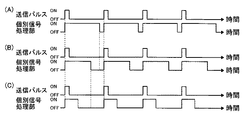
図示例において、所定深度よりも深い領域での音線数の減少は、信号処理部20の個別信号処理部20a(そのAFE)の駆動のon/offによって行なう。
深度L1すなわち音線数の減少を行なわない場合には、全ての音線で、図4(A)に概念的に示すように、送信パルスのonと同時に個別信号処理部20aの駆動もonして、深度L1(合成超音波画像に対応する深度)に対応する時間で、個別信号処理部20aの駆動をoffする。
In the illustrated example, the number of sound rays in a region deeper than a predetermined depth is reduced by turning on / off driving of the individual
When the depth L1, that is, when the number of sound rays is not reduced, the drive of the individual
また、深度L2で音線数を減少する場合には、図4(B)に概念的に示すように、送信パルスのonと同時に個別信号処理部20aの駆動もonして、対応する音線(所定深度で減少される音線)については、深度L1よりも短い深度L2に対応する時間となったら、個別信号処理部20aの駆動をoffする。
すなわち、1本おきに音線を減少する本例では、個別信号処理部20aでは、音線1本おきに、図4(A)の駆動と図4(B)の駆動とが交互に行なわれる。
When the number of sound rays is decreased at the depth L2, as shown conceptually in FIG. 4B, the drive of the individual
That is, in the present example in which the sound lines are reduced every other line, the individual
さらに、深度L3で音線数を減少する場合には、図4(C)に概念的に示すように、送信パルスのonと同時に個別信号処理部20aの駆動もonして、対応する音線については、深度L2よりも短い、最短の深度L3に対応する時間となったら、個別信号処理部20aの駆動をoffする。
すなわち、1本おきに音線を減少する本例では、個別信号処理部20aは、音線1本おきに、図4(A)の駆動と図4(C)の駆動とが交互に行なわれる。
Further, when the number of sound rays is decreased at the depth L3, as conceptually shown in FIG. 4C, the drive of the individual
That is, in this example in which the sound lines are reduced every other line, the individual
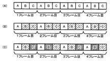
前述のように、図示例の超音波診断装置10においては、図3および図5に概念的に示すように、空間コンパウンドを行なう際には、互いに超音波の送受信方向が異なる、3種類(3画像分)の超音波の送受信を、1つの合成超音波画像を得るための1つのフレーム(単位)として、この1フレームの送受信を繰り返し行なう。 As described above, in the illustrated ultrasonic diagnostic apparatus 10, as conceptually shown in FIGS. 3 and 5, when performing spatial compounding, three types (3 The transmission / reception of ultrasonic waves (images) is repeated as one frame (unit) for obtaining one synthesized ultrasonic image.
一例として、図3および図5に示すように、送信制御部32および受信制御部34は、まず、超音波画像Aを得るための通常の送受信を行なうように、送信駆動部30および各個別信号処理部20aの駆動を制御する。以下、便宜的に、この通常の送受信を「画像Aの送受信」とする。
次いで、送信制御部32および受信制御部34は、超音波画像Bを得るための、通常の送受信に対して、角度をθ傾けた方向の送受信を行なうように、送信駆動部30および各個別信号処理部20aの駆動を制御する。以下、便宜的に、この角度をθ傾けた送受信を「画像Bの送受信」とする。
さらに、送信制御部32および受信制御部34は、超音波画像Cを得るための、通常の送受信に対して、角度を−θ傾けた方向の送受信をを行なうように、送信駆動部30および各個別信号処理部20aの駆動を制御する。以下、便宜的に、この角度を−θ傾けた送受信を「画像Cの送受信」とする。
As an example, as shown in FIGS. 3 and 5, the
Next, the
Furthermore, the
ここで、図5においては、深度L1(通常深度)すなわち音線数の減少を行なわない画像の送受信を白抜きで、深度L2(中間深度)で音線数を減少する画像の送受信を粗いハッチ(斜線)で、深度L3(短深度)で音線数を減少する画像を密なハッチで、それぞれ示す。 Here, in FIG. 5, transmission / reception of an image without decreasing the depth L1 (normal depth), that is, the number of sound rays is outlined, and transmission / reception of an image with the number of sound rays decreasing at the depth L2 (intermediate depth) is rough. In (hatched line), images in which the number of sound rays is decreased at a depth L3 (short depth) are shown by dense hatches, respectively.
超音波診断装置10のプローブ12は、空間コンパウンドを行なう際に、温度測定手段42による温度測定結果がT1未満の場合には、受信制御部34は、図5(A)に示すように、1つのフレームにおいて、画像Aの送受信、画像Bの送受信、および画像Cの送受信における全てで、音線数の減少を行なわないように(受信信号の処理を深度L1まで行なうように)、個別信号処理部20aの駆動を制御する。
温度測定手段42による温度測定結果がT1未満の場合とは、すなわち、プローブ12(信号処理部20)の温度が定常状態である場合である。
When the
The case where the temperature measurement result by the temperature measuring means 42 is less than T1 is the case where the temperature of the probe 12 (signal processing unit 20) is in a steady state.
また、温度測定手段42による温度測定結果がT1以上T2未満の場合には、受信制御部34は、図5(B)に示すように、1つのフレームにおいて、画像Aの送受信では音線数の減少を行なわず、画像Bおよび画像Cの送受信では深度L2で音線数を減少するように、個別信号処理部20aの駆動を制御する。
すなわち、この処理では、圧電素子ユニット16から遠い領域(深度L2よりも深い領域)は、空間コンパウンドによる画像の画質が低下する。
When the temperature measurement result by the temperature measurement means 42 is T1 or more and less than T2, the
In other words, in this process, the image quality of the image due to the spatial compound is deteriorated in the region far from the piezoelectric element unit 16 (the region deeper than the depth L2).
さらに、温度測定手段42による温度測定結果がT2以上の場合には、受信制御部34は、図5(C)に示すように、1つのフレームにおいて、画像Aの送受信では音線数の減少を行なわず、画像Bおよび画像Cの送受信では深度L3で音線数を減少するように、個別信号処理部20aの駆動を制御する。
すなわち、この処理では、圧電素子ユニット16の近傍よりも深い領域(深度L3よりも深い領域)は、空間コンパウンドによる画像の画質が低下する。
Furthermore, when the temperature measurement result by the temperature measurement means 42 is T2 or more, the
That is, in this process, the image quality of the image due to the spatial compound is lowered in a region deeper than the vicinity of the piezoelectric element unit 16 (region deeper than the depth L3).
以上の説明より明らかなように、本発明の超音波診断装置10では、空間コンパウンドを行なう際に、プローブ12の温度が上昇した場合には、合成超音波画像となる超音波画像を得るための超音波送受信での受信信号の処理によって、所定深度よりも深い領域で超音波画像の音線数を減少する。すなわち、本発明の超音波診断装置10では、プローブ12の温度が上昇した場合には、その温度に応じて、超音波エコーの受信信号を処理する個別信号処理部20aの駆動時間を短縮する。
従って、本発明においては、空間コンパウンドを行なっている際に、プローブ12の温度が上昇しても、最も大きな発熱部である信号処理部20を休止させることで、プローブ12内の温度を速やかに低下することができる。また、プローブ12内の温度上昇を抑制し、かつ、速やかに低下させることにより、プローブ12の温度上昇が生じても、画質劣化を最小限に抑えることができる。
As is clear from the above description, in the ultrasonic diagnostic apparatus 10 of the present invention, when the temperature of the
Therefore, in the present invention, even when the temperature of the
図5に示す例では、合成超音波画像となる1フレームは、全て受信信号の処理深度は同じであるが、本発明は、これに限定はされず、各フレーム(各合成超音波画像)において、1以上の超音波画像の受信信号の処理深度が異なってもよい。 In the example shown in FIG. 5, the processing depth of the received signal is the same for all the frames that become the synthesized ultrasound image, but the present invention is not limited to this, and in each frame (each synthesized ultrasound image) The processing depths of the received signals of one or more ultrasonic images may be different.
例えば、図5に示す例では、温度測定手段42による温度測定結果がT2以上の場合に、全てのフレームで、画像Bおよび画像Cの送受信において深度L3で音線数を減少したが、本発明は、これに限定はされない。
一例として、先と同様、温度測定手段42による温度測定結果がT1未満の場合には、図6(A)に示すように、全ての画像の送受信で音線数の減少を行なわず、同温度測定結果がT1以上T2未満の場合には、図6(B)に示すように、画像Aの送受信は音線数を減少せず、画像Bおよび画像Cの送受信は、深度L2で音線数を減少する。
これに対して、温度測定手段42による温度測定結果がT2以上の場合には、例えば、図6(C)に示すように、画像Aの送受信は同様に全てのフレームで音線数の減少は行なわず、奇数フレームでは、画像Bおよび画像Cの送受信において深度L3で音線数を減少し、偶数フレームでは、画像Bおよび画像Cの送受信において深度L2で音線数を減少するようにしてもよい。
この例によれば、1フレームおきに、音線数の減少深度を深くできるので、図5に示す例と比べて、空間コンパウンドで生成される画像を連続画像として観察した際に、深度L2〜L3の区間の画質劣化を、低減できる。
For example, in the example shown in FIG. 5, when the temperature measurement result by the temperature measurement means 42 is T2 or more, the number of sound rays is reduced at the depth L3 in transmission / reception of the images B and C in all frames. Is not limited to this.
As an example, when the temperature measurement result by the temperature measurement means 42 is less than T1, as in the previous case, as shown in FIG. When the measurement result is T1 or more and less than T2, as shown in FIG. 6B, the transmission / reception of the image A does not decrease the number of sound rays, and the transmission / reception of the image B and the image C is performed at the depth L2. Decrease.
On the other hand, when the temperature measurement result by the temperature measuring means 42 is T2 or more, for example, as shown in FIG. Without being performed, the number of sound rays is decreased at the depth L3 in transmission / reception of the images B and C in the odd frames, and the number of sound rays is decreased at the depth L2 in transmission / reception of the images B and C in the even frames. Good.
According to this example, since the depth of decrease of the number of sound rays can be increased every other frame, when the image generated by the spatial compound is observed as a continuous image as compared with the example illustrated in FIG. It is possible to reduce image quality degradation in the section L3.
以上の例においては、温度測定手段42による温度測定結果が、T1以上T2未満の場合、および、T2以上の場合には、1つのフレームの中で、音線数を減少する画像は、共に同じ深度で音線数を減少しているが、本発明は、これに限定はされない。
すなわち、1フレームの中で、深度L2での音線数の減少と、深度L3での音線数の減少とが混在してもよい。また、1フレームの中で、音線数の減少無しと、深度L2での音線数の減少と、深度L3での音線数の減少とが、混在してもよい。
In the above example, when the temperature measurement result by the temperature measurement means 42 is T1 or more and less than T2, and when it is T2 or more, the images in which the number of sound rays is reduced in one frame are the same. Although the number of sound rays is decreased at the depth, the present invention is not limited to this.
That is, a decrease in the number of sound rays at the depth L2 and a decrease in the number of sound rays at the depth L3 may be mixed in one frame. Further, in one frame, no decrease in the number of sound rays, a decrease in the number of sound rays at the depth L2, and a decrease in the number of sound rays at the depth L3 may be mixed.
一例として、図7に概念的に示す受信信号の処理が例示される。
この例では、温度測定手段42による温度測定結果がT1未満の場合には、先の例と同様、図7(A)に示すように、画像A、画像Bおよび画像Cの送受信の全てで、音線数の減少は行なわない。また、温度測定手段42による温度測定結果がT1以上T2未満の場合にも、先の例と同様、図7(B)に示すように、画像Aの送受信では音線数の減少は行なわず、画像Bおよび画像Cの送受信では深度L2で音線数を減少する。
これに対し、本例では、温度測定手段42による温度測定結果がT2以上である場合には、図7(C)に示すように、画像Aの送受信では音線数の減少は行なわず、画像Bの送受信では深度L2で音線数を減少し、画像Cの送受信では深度L3で音線数を減少する。あるいは、画像Aを深度L1、画像Bを深度L3、画像Cを深度L2としてもよい。
この例によれば、図5に示す例に比して、発熱防止効果は低減するが、合成超音波画像の画質的には有利である。
As an example, the received signal processing conceptually shown in FIG. 7 is illustrated.
In this example, when the temperature measurement result by the temperature measuring means 42 is less than T1, as in the previous example, as shown in FIG. The number of sound rays is not reduced. Also, when the temperature measurement result by the temperature measuring means 42 is T1 or more and less than T2, as shown in FIG. 7B, the number of sound rays is not reduced in the transmission / reception of the image A, as shown in FIG. In transmission / reception of images B and C, the number of sound rays is decreased at depth L2.
On the other hand, in this example, when the temperature measurement result by the temperature measuring means 42 is T2 or more, as shown in FIG. In the transmission / reception of B, the number of sound rays is decreased at the depth L2, and in the transmission / reception of the image C, the number of sound rays is decreased at the depth L3. Alternatively, the image A may be the depth L1, the image B may be the depth L3, and the image C may be the depth L2.
According to this example, the heat generation prevention effect is reduced as compared with the example shown in FIG. 5, but it is advantageous in terms of the image quality of the synthesized ultrasonic image.
また、この例においては、温度測定手段42による温度測定結果が、T2以上である場合には、画像Bと画像Cとで、深度L2での音線数の減少と、深度L3での音線数の減少とを、交互に行なってもよい。
一例として、先と同様、温度測定手段42による温度測定結果がT1未満の場合には、図8(A)に示すように、全ての画像の送受信で音線数の減少を行なわず、同温度測定結果がT1以上T2未満の場合には、図8(B)に示すように、画像Aの送受信は音線数を減少せず、画像Bおよび画像Cの送受信は、深度L2で音線数を減少する。
これに対して、温度測定手段42による温度測定結果がT2以上の場合には、例えば、図8(C)に示すように、画像Aの送受信は、同様に全てのフレームで音線数の減少は行なわず、奇数フレームでは、画像Bの送受信では深度L2で音線数を減少して、画像Cの送受信では深度L3で音線数を減少し、偶数フレームでは、画像Bの送受信では深度L3で音線数を減少し画像Cの送受信では深度L2で音線数を減少するようにしてもよい。
この例では、空間コンパウンドで合成する超音波画像において、1フレームおきに、音線数が深度L3以降で減少する領域が置き換わるので、合成超音波画像中において連続的に画質が劣化する領域を無くすことができ、これにより空間コンパウンドで生成される画像を連続画像として観察した際の画質劣化を、低減できる。
Further, in this example, when the temperature measurement result by the temperature measuring means 42 is equal to or greater than T2, in the images B and C, the number of sound rays at the depth L2 decreases and the sound rays at the depth L3. The reduction of the number may be performed alternately.
As an example, when the temperature measurement result by the temperature measuring means 42 is less than T1, as in the previous case, as shown in FIG. When the measurement result is T1 or more and less than T2, as shown in FIG. 8B, the transmission / reception of the image A does not decrease the number of sound rays, and the transmission / reception of the image B and the image C is performed at the depth L2. Decrease.
On the other hand, when the temperature measurement result by the temperature measurement means 42 is equal to or greater than T2, for example, as shown in FIG. 8C, the transmission / reception of the image A similarly reduces the number of sound rays in all frames. In the odd-numbered frame, the number of sound rays is decreased at the depth L2 in the transmission / reception of the image B, the number of sound rays is decreased in the depth L3 in the transmission / reception of the image C, and the depth L3 is determined in the transmission / reception of the image B The number of sound rays may be reduced, and the number of sound rays may be reduced at the depth L2 in transmission / reception of the image C.
In this example, an area where the number of sound rays decreases after the depth L3 is replaced every other frame in the ultrasonic image synthesized by the spatial compound, so that the area where the image quality continuously deteriorates is eliminated in the synthesized ultrasonic image. Accordingly, it is possible to reduce image quality degradation when an image generated by the spatial compound is observed as a continuous image.
なお、以上の例では、プローブ12内の温度が上昇した場合に、所定深度よりも深い領域で音線数を減少するのは、画像Bの送受信および/または画像Cの送受信であるが、本発明は、これに限定はされない。すなわち、温度上昇に応じて、画像Aの送受信において所定深度よりも深い領域で音線数を減少してもよい。
しかしながら、診断装置本体14で生成する合成超音波画像は、超音波画像Aの領域の画像で、すなわち空間コンパウンドにおける主画像は超音波画像A(画像Aの送受信)である。従って、1つのフレームの中に深度L1までの受信信号処理が含まれる場合には、画像Aの送受信(すなわち合成超音波画像の全域を包含する送受信)では、音線数を減少しない方が、安定して適正な合成超音波画像を得ることができる。
In the above example, when the temperature in the
However, the synthesized ultrasonic image generated by the diagnostic apparatus
また、以上の例では、少なくとも1画像(画像Aの送受信)は、全ての温度において、音線数を減少しない(深度L1まで)としたが、本発明は、これに限定はされず、温度に応じて、全ての画像の送受信で、深度L2や深度L3で音線数を減少してもよい。
としてもよい。
Further, in the above example, at least one image (transmission / reception of image A) does not reduce the number of sound rays at all temperatures (up to depth L1). However, the present invention is not limited to this, and the temperature Accordingly, the number of sound rays may be reduced at the depth L2 or the depth L3 in transmission / reception of all images.
It is good.
一例として、図9に概念的に示す超音波の送受信が例示される。
この例では、温度測定手段42による温度測定結果がT1未満の場合には、先の例と同様、図9(A)に示すように、画像A、画像Bおよび画像Cの送受信の全てで、音線の減少は行なわない。また、温度測定手段42による温度測定結果が、T1以上T2未満の場合にも、先の例と同様、図9(B)に示すように、画像Aの送受信では音線の減少は行なわず、画像Bおよび画像Cの送受信では深度L2で音線を減少する。。
これに対し、この例では、温度測定手段42による温度測定結果が、T2以上である場合には、図9(C)に示すように、画像Aの送受信では深度L2で音線を減少し、画像Bのおよび画像Cの送受信では、深度L3で音線を減少する。
この例によれば、得られる合成超音波画像の画質が全体的に劣化するが、発熱防止効果は大きくなる。
As an example, transmission / reception of ultrasonic waves conceptually shown in FIG. 9 is illustrated.
In this example, when the temperature measurement result by the temperature measurement means 42 is less than T1, as in the previous example, as shown in FIG. 9A, in all transmission / reception of images A, B and C, The sound ray is not reduced. Further, even when the temperature measurement result by the temperature measuring means 42 is T1 or more and less than T2, as in the previous example, as shown in FIG. In transmission / reception of the image B and the image C, the sound ray is reduced at the depth L2. .
On the other hand, in this example, when the temperature measurement result by the temperature measurement means 42 is T2 or more, as shown in FIG. 9C, the sound ray is reduced at the depth L2 in the transmission / reception of the image A, In transmission / reception of the image B and the image C, the sound ray is reduced at the depth L3.
According to this example, the image quality of the resultant synthesized ultrasonic image is deteriorated as a whole, but the effect of preventing heat generation is increased.
以上の例では、温度測定手段42による温度測定結果に応じて、温度T1以上となった場合には、1フレーム中で2つの画像の送受信で所定深度よりも深い領域で音線数を減少したが、本発明は、これに限定はされない。すなわち、温度測定手段42による温度測定結果に応じて、1フレーム中で1画像の送受信のみ音線数を所定深度以降で減少してもよく、1フレーム中で3画像以上の送受信で音線数を所定深度以降で減少してもよい。
ただ、プローブ12内の温度上昇を抑制し、かつ、温度上昇に起因する画質劣化を最小限にするという目的を考慮すると、温度が閾値以上となった場合には、1フレーム中で2画像以上で音線数を所定深度以降で減少するのが好ましく、さらに、画像A(主画像)以外の全画像の音線数を、温度に応じて所定深度よりも深い領域で減少するのが好ましい。
In the above example, according to the temperature measurement result by the temperature measuring means 42, when the temperature is equal to or higher than T1, the number of sound rays is reduced in a region deeper than a predetermined depth by transmitting and receiving two images in one frame. However, the present invention is not limited to this. That is, according to the temperature measurement result by the temperature measuring means 42, the number of sound rays may be decreased only after transmission / reception of one image in one frame after a predetermined depth, or the number of sound rays of transmission / reception of three images or more in one frame. May be decreased after a predetermined depth.
However, in consideration of the purpose of suppressing the temperature rise in the
さらに、以上の例では、空間コンパウンドを行なう場合の所定数が3であるので、温度の閾値を2点にしたが、本発明は、これに限定はされず、所定数が4以上の場合には、閾値を3点以上設けてもよい。
また、温度に応じて音線数を減少する深度も、3つに限定はされない。例えば、通常深度(L1)と短深度(L3)との2つであってもよく、通常深度と短深度との間に、深度L2−1、深度L2−2…のように、複数点の中間深度を設定して、温度に応じて音線数を減少する深度を4以上としてもよい。
Further, in the above example, since the predetermined number when performing spatial compounding is 3, the threshold value of the temperature is set to two points. However, the present invention is not limited to this, and the predetermined number is 4 or more. May provide three or more threshold values.
Further, the depth at which the number of sound rays is decreased according to the temperature is not limited to three. For example, the normal depth (L1) and the short depth (L3) may be two, and a plurality of points such as a depth L2-1, a depth L2-2,... An intermediate depth may be set, and the depth at which the number of sound rays is decreased according to the temperature may be 4 or more.
図5〜図9に示す例においては、1つのフレームにおける送受信の順序は、全てのフレームで同一であるが、本発明は、これに限定はされず、各フレームで、各画像の送受信の順序が異なってもよい。
例えば、図10に一例を示すように、1フレーム目を「画像Aの送受信(以下、省略)→画像B→画像C」、2フレーム目を「画像C→画像B→画像A」、3フレーム目を「画像A→画像B→画像C」、4フレーム目を「画像C→画像B→画像A」………のようにしてもよい。
In the example shown in FIGS. 5 to 9, the order of transmission / reception in one frame is the same in all frames, but the present invention is not limited to this, and the order of transmission / reception of each image in each frame. May be different.
For example, as shown in FIG. 10, the first frame “image A transmission / reception (hereinafter omitted) → image B → image C”, the second frame “image C → image B → image A”, and three frames The first frame may be “image A → image B → image C”, and the fourth frame may be “image C → image B → image A”.
すなわち、本発明においては、連続するフレーム(すなわち、時間的に連続する合成超音波画像)において、最も近接する超音波画像の送受信方向を、同方向にしてもよい。
このような送受信の順序によれば、同方向の送受信が連続するので、送信駆動部30や個別信号処理部20aの制御を、簡略化することができる。
That is, in the present invention, the transmission / reception directions of the closest ultrasonic images may be the same in consecutive frames (that is, synthesized ultrasonic images that are temporally continuous).
According to such a transmission / reception order, transmission / reception in the same direction is continued, so that control of the
前述のように、プローブ12が出力する受信信号は、無線通信によって、診断装置本体14に供給される。
診断装置本体14は、アンテナ50が接続される無線通信部52を有し、この無線通信部52にシリアル/パラレル変換部54を介してデータ格納部56が接続され、データ格納部56に画像生成部58が接続されている。さらに、画像生成部58に表示制御部62を介して表示部64が接続されている。
また、無線通信部52に通信制御部68が接続され、シリアル/パラレル変換部54、画像生成部58、表示制御部62および通信制御部68に本体制御部70が接続されている。本体制御部70は、診断装置本体14内の各部の制御を行うものであり、空間コンパウンドの実施の有無等の各種の入力操作を行うための操作部72が接続されている。
As described above, the reception signal output from the
The diagnostic apparatus
A
なお、診断装置本体14は、図示を省略する電源部が内蔵されており、この電源部から、各部位に駆動のための電力が供給される。
また、診断装置本体14には、プローブ12に内蔵されるバッテリに充電を行なうための、充電手段を有してもよい。
The diagnostic device
Further, the diagnostic device
無線通信部52は、プローブ12との間で無線通信を行うことにより、各種の制御信号をプローブ12に送信する。また、無線通信部52は、アンテナ50によって受信される信号を復調することにより、シリアルのサンプルデータを出力する。
通信制御部68は、本体制御部70によって設定された送信電波強度で各種の制御信号の送信が行われるように、無線通信部52を制御する。
シリアル/パラレル変換部54は、無線通信部52から出力されるシリアルのサンプルデータを、パラレルのサンプルデータに変換する。データ格納部56は、メモリまたはハードディスク等によって構成され、シリアル/パラレル変換部54によって変換された少なくとも1フレーム分のサンプルデータを格納する。
The
The
The serial /
画像生成部58は、データ格納部56から読み出した1画像毎のサンプルデータに受信フォーカス処理等を施して、超音波画像を表す画像信号を生成する。この画像生成部は、整相加算部76と、画像処理部78と、画像合成部80とを有する。
The
整相加算部76は、本体制御部21において設定された受信方向に応じて、予め記憶されている複数の受信遅延パターンの中から1つの受信遅延パターンを選択し、選択された受信遅延パターンに基づいて、サンプルデータによって表される複数の複素ベースバンド信号にそれぞれの遅延を与えて加算することにより、受信フォーカス処理を行う。この受信フォーカス処理により、超音波エコーの焦点が絞り込まれたベースバンド信号(音線信号)が生成される。
The
ここで、本発明の超音波診断装置10においては、前述のように、空間コンパウンドを行なう際には、プローブ12は、温度測定手段42による測定温度に応じて、超音波エコーの受信において、所定深度よりも深い領域の音線数を減少する。すなわち、温度測定手段42による測定温度に応じて、超音波画像の所定深度よりも深い領域いおいて、音線数を減少する。
整相加算部76は、空間コンパウンドを行なう際に、所定深度よりも深い領域で音線数が減少された超音波画像に関しては、減少された音線を隣接する音線(周囲の音線)で補間して、減少された音線を生成し、超音波画像全体の音線(音線信号)を生成する。
なお、補間の方法には、特に限定はなく、各種の画像処理等で行なわれている公知の補間方法が、全て利用可能である。
Here, in the ultrasonic diagnostic apparatus 10 according to the present invention, as described above, when performing spatial compounding, the
When the
The interpolation method is not particularly limited, and all known interpolation methods performed in various image processing and the like can be used.
画像処理部78は、整相加算部76によって生成される音線信号に基づいて、被検体内の組織に関する断層画像情報である超音波画像(Bモード画像)の画像信号を生成する。
画像処理部78は、STC(sensitivity time control)部と、DSC(digital scan converter:デジタル・スキャン・コンバータ)とを含んでいる。STC部は、音線信号に対して、超音波の反射位置の深度に応じて、距離による減衰の補正を施す。DSCは、STC部によって補正された音線信号を通常のテレビジョン信号の走査方式に従う画像信号に変換(ラスター変換)し、階調処理等の必要な画像処理を施すことにより、超音波画像信号を生成する。
The
The
画像合成部80は、空間コンパウンドを行なう際に、画像処理部78が生成した超音波画像の合成を行なう。
前述のように、プローブ12では、空間コンパウンドを行なう際には、画像Aの送受信、画像Bの送受信、および画像Cの送受信の、3画像分(3種類)の超音波の送受信を行なう。
これに応じて、空間コンパウンドを行なう際には、画像合成部80は、画像Aの送受信による超音波画像A、画像Bの送受信による超音波画像B、および画像Cの送受信による超音波画像Cの合成を行い、合成超音波画像の画像信号を生成する。
The
As described above, when performing spatial compounding, the
In response to this, when performing spatial compounding, the
表示制御部62は、画像生成部58によって生成される画像信号に基づいて、表示部64に超音波画像を表示させる。
表示部64は、例えば、LCD等のディスプレイ装置を含んでおり、表示制御部62の制御の下で、超音波画像を表示する。
The
The
以下、図1に示す超音波診断装置10の作用を説明する。
超音波診断装置10において、診断時には、まず、プローブ12の送信駆動部30から供給される駆動電圧に従って、複数のトランスデューサ18から超音波が送信される。
この超音波は、被検体によって反射され、被検体からの超音波エコーを受信した各トランスデューサ18から出力された受信信号がそれぞれ対応する個別信号処理部20aに供給されてサンプルデータが生成される。
Hereinafter, the operation of the ultrasonic diagnostic apparatus 10 shown in FIG. 1 will be described.
In the ultrasonic diagnostic apparatus 10, at the time of diagnosis, first, ultrasonic waves are transmitted from the plurality of
The ultrasonic waves are reflected by the subject, and the reception signals output from the
ここで、プローブ12では、空間コンパウンドを行なう場合には、温度測定手段42による信号処理部20の温度測定結果が受信制御部34に送られる。
前述のように、超音波診断装置10では、空間コンパウンドを行なう際には、プローブ12は、温度測定手段42による受信処理部20の測定温度結果に応じて、超音波画像の音線数を所定深度以降で減少する。具体的には、プローブ12は、温度測定手段42による測定温度結果に応じて、温度が閾値を一段階上がる毎に、合成する超音波画像の何れかの音線数の減少深度が「深度L1→深度L2→深度L3」の順で浅くなるように、受信信号を処理する個別信号処理部20aの駆動を制御する。
一例として、受信制御部34は、この温度測定結果に応じて、温度測定手段42による測定温度が温度がT1未満の場合には、図5(A)に示すように、画像A、画像Bおよび画像Cの送受信の全てで音線の減少を行なわないように、信号処理部20(個別信号処理部20a)の動作を制御する。
また、受信制御部34は、温度測定手段42による測定温度がT1以上T2未満の場合には、図5(B)に示すように、画像Aの送受信では音線の減少を行なわず、画像Bおよび画像Cの送受信では、1本おきに深度L2で音線を減少するように、信号処理部20の動作を制御する。
さらに、受信制御部34は、温度測定手段42による測定温度がT2以上の場合には、図5(C)に示すように、画像Aの送受信では音線の減少を行なわず、画像Bおよび画像Cの送受信では、1本おきに深度L3で音線を減少するように、信号処理部20の動作を制御する。
Here, in the
As described above, in the ultrasonic diagnostic apparatus 10, when performing spatial compounding, the
As an example, when the temperature measured by the
In addition, when the temperature measured by the
Further, when the temperature measured by the temperature measuring means 42 is equal to or higher than T2, the
個別信号処理部20aで生成されたサンプルデータは、パラレル/シリアル変換部24に送られて、シリアル化された後に無線通信部26(アンテナ28)から診断装置本体14へ無線伝送される。
The sample data generated by the individual
診断装置本体14の無線通信部52で受信されたサンプルデータは、シリアル/パラレル変換部54でパラレルのデータに変換され、データ格納部56に格納される。
さらに、データ格納部56から1画像毎のサンプルデータが読み出され、画像生成部58で超音波画像の画像信号が生成され、この画像信号に基づいて表示制御部62により超音波画像が表示部64に表示される。
The sample data received by the
Further, sample data for each image is read from the
空間コンパウンドを行なう場合には、画像生成部58の整相加算部76において、プローブ12で減少された音線の補間が行なわれ、さらに、画像合成部80において、超音波画像の合成が行なわれる。
ここで、前述のように、超音波診断装置10では、空間コンパウンドを行なう際には、プローブ12は、温度測定手段42による受信処理部20の測定温度結果に応じて、合成する超音波画像の音線数を所定深度以降で減少する。具体的には、プローブ12は、温度測定手段42による測定温度結果に応じて、合成する超音波画像の何れかの音線数を、深度L2および深度L3の何れか以降で減少させる。
例えば、前述の図5に示す例であれば、空間コンパウンドを行なう場合には、プローブ12では、温度測定手段42による測定温度に応じて、超音波の送受信において、温度がT1未満の場合には音線数の減少はせず、測定温度がT1以上T2未満の場合には、深度L2よりも深い領域で1本起きに音線を減少し、測定温度がT2以上の場合には、深度L3よりも深い領域で1本起きに音線を減少する。
これに応じて、整相加算部76は、空間コンパウンドを行なう場合には、深度L2もしくは深度L3よりも深い領域で音線数を減少された画像は、減少された音線(無い音線)を、隣接する音線で補間して、1つの超音波画像の全域に対応する音線を生成して、画像合成部80に送る。
When performing spatial compounding, the phasing and adding
Here, as described above, in the ultrasonic diagnostic apparatus 10, when performing spatial compounding, the
For example, in the example shown in FIG. 5 described above, when performing spatial compounding, the
In response to this, when the
画像合成部80は、空間コンパウンドを行なう場合には、整相加算部76が生成した、画像Aの送受信による超音波画像A、画像Bの送受信による超音波画像B、および画像Cの送受信による超音波画像Cの合成を行い、合成超音波画像の画像信号を生成し、表示制御部62に出力する。
When performing spatial compounding, the
以上、本発明の超音波診断装置について詳細に説明したが、本発明は、上述の例に限定はされず、本発明の要旨を逸脱しない範囲において、各種の改良や変更を行なってもよいのは、もちろんである。 Although the ultrasonic diagnostic apparatus of the present invention has been described in detail above, the present invention is not limited to the above-described example, and various improvements and modifications may be made without departing from the gist of the present invention. Of course.
医療現場等で各種の診断に用いられる超音波診断装置に、好適に利用可能である。 It can be suitably used for an ultrasonic diagnostic apparatus used for various diagnoses in a medical field.
10 超音波診断装置
12 (超音波)プローブ
14 診断装置本体
16 圧電素子ユニット
18 トランスデューサ
20 信号処理部
20a 個別信号処理部
24 パラレル/シリアル変換部
26,52 無線通信部
28,50 アンテナ
30 送信駆動部
32 送信制御部
34 受信制御部
36 通信制御部
38 プローブ制御部
42 温度測定手段
54 シリアル/パラレル変換部
56 データ格納部
58 画像生成部
62 表示制御部
64 表示部
68 通信制御部
70 本体制御部
72 操作部
76 整相加算部
78 画像処理部
80 画像合成部
DESCRIPTION OF SYMBOLS 10 Ultrasonic diagnostic apparatus 12 (Ultrasound)
Claims (9)
前記超音波プローブの信号処理手段が処理した受信信号に応じた超音波画像を生成する診断装置本体とを有し、
前記診断装置本体は、所定数の前記超音波画像を合成して1つの合成超音波画像を生成する機能を有し、また、前記超音波プローブは、前記診断装置本体が合成超音波画像の生成を行なうために、超音波の送受信方向が互いに異なる前記所定数と同数の複数種類の超音波の送受信を行なう機能を有し、
かつ、前記超音波プローブは、前記診断装置本体が合成超音波画像の生成を行なう際には、前記温度測定手段による温度測定結果に応じて、前記診断装置本体が合成する超音波画像の所定深度よりも深い領域の音線数を減少するように、前記信号処理手段による受信信号の処理を調整し、さらに、前記診断装置本体は、前記所定深度以降で減少された音線は、周囲の音線を用いて補間して前記超音波画像を生成することを特徴とする超音波診断装置。 Piezoelectric element unit that transmits ultrasonic waves, receives ultrasonic echoes reflected by the subject, and outputs a received signal corresponding to the received ultrasonic waves, and transmission control means for controlling transmission of ultrasonic waves by the piezoelectric element units An ultrasonic probe having signal processing means for processing the received signal output from the piezoelectric element unit, and temperature measuring means for measuring the temperature at a predetermined position;
A diagnostic apparatus main body that generates an ultrasonic image according to the received signal processed by the signal processing means of the ultrasonic probe;
The diagnostic apparatus main body has a function of generating a single synthesized ultrasonic image by synthesizing a predetermined number of the ultrasonic images, and the ultrasonic probe generates a synthetic ultrasonic image by the diagnostic apparatus main body. In order to perform the transmission and reception of ultrasonic waves of the same number as the predetermined number different from each other has a function of transmitting and receiving a plurality of types of ultrasonic waves,
The ultrasonic probe has a predetermined depth of the ultrasonic image synthesized by the diagnostic apparatus main body according to the temperature measurement result by the temperature measuring means when the diagnostic apparatus main body generates a synthetic ultrasonic image. The processing of the received signal by the signal processing means is adjusted so as to reduce the number of sound rays in a deeper region, and the diagnostic device body further reduces the sound rays reduced after the predetermined depth to the surrounding sound. An ultrasonic diagnostic apparatus, wherein the ultrasonic image is generated by interpolation using lines.
さらに、前記音線数を減少する所定深度として、音線数を減少しない通常深度、深度が最も浅い短深度、および、前記通常深度と短深度との間の深度である中間深度が設定されている請求項1または2に記載の超音波診断装置。 As the temperature threshold, a temperature T1 and a temperature T2 higher than the temperature T1 are set.
Further, as the predetermined depth for reducing the number of sound rays, a normal depth that does not reduce the number of sound rays, a shortest depth at which the depth is the shallowest, and an intermediate depth that is a depth between the normal depth and the short depth are set. The ultrasonic diagnostic apparatus according to claim 1 or 2.
この温度測定結果が前記温度T1以上温度T2未満の場合には、前記所定数の超音波画像のうちの2以上を、前記中間深度で音線数を減少し、
この温度測定結果が前記温度T2以上の場合には、前記所定数の超音波送画像のうちの2以上を、前記短深度で音線数を減少する請求項3または4に記載の超音波診断装置。 When the diagnostic apparatus main body generates a synthetic ultrasound image, the ultrasound probe is in accordance with the temperature measurement result by the temperature measurement means,
When the temperature measurement result is equal to or higher than the temperature T1 and lower than the temperature T2, the number of sound rays is reduced at the intermediate depth of two or more of the predetermined number of ultrasonic images,
5. The ultrasonic diagnosis according to claim 3, wherein when the temperature measurement result is equal to or higher than the temperature T <b> 2, the number of sound rays is decreased at the short depth for two or more of the predetermined number of ultrasonic transmission images. apparatus.
温度測定結果が前記温度T1以上温度T2未満の場合には、前記所定数の超音波送画像のうちの2以上を、前記中間深度で音線数を減少し、
温度測定結果が前記温度T2以上の場合には、前記所定数の超音波送画像の少なくとも1つで、前記中間深度で音線数を減少し、他の少なくとも1つで、前記短深度で音線数を減少する請求項3または4に記載の超音波診断装置。 When the diagnostic apparatus main body generates a synthetic ultrasound image, the ultrasound probe is in accordance with the temperature measurement result by the temperature measurement means,
When the temperature measurement result is equal to or higher than the temperature T1 and lower than the temperature T2, the number of sound rays is reduced at the intermediate depth for two or more of the predetermined number of ultrasonic transmission images,
When the temperature measurement result is equal to or higher than the temperature T2, the number of sound rays is decreased at the intermediate depth in at least one of the predetermined number of ultrasonic transmission images, and the sound at the short depth is decreased at at least one other. The ultrasonic diagnostic apparatus according to claim 3 or 4, wherein the number of lines is reduced.
かつ、この主画像の超音波の送受信で得られる超音波画像は、前記通常深度とする請求項3〜6のいずれかに記載の超音波診断装置。 When the diagnostic apparatus main body generates a synthetic ultrasonic image, the ultrasonic probe includes an ultrasonic wave that covers the entire area to be output as the synthetic ultrasonic image once in the plurality of types of ultrasonic transmission / reception. Send and receive ultrasound of the main image from which the image is obtained,
The ultrasonic diagnostic apparatus according to claim 3, wherein an ultrasonic image obtained by transmitting / receiving ultrasonic waves of the main image has the normal depth.
この温度測定結果が前記温度T1以上温度T2未満の場合には、前記所定数の超音波画像のうちの2以上を、前記中間深度で音線数を減少し、
温度測定結果が前記温度T2以上の場合には、前記所定数の超音波画像のうちの2以上を、前記短深度で音線数を減少し、それ以外を全て前記中間深度で音線数を減少する請求項3または4に記載の超音波診断装置。 When the diagnostic apparatus main body generates a synthetic ultrasound image, the ultrasound probe is in accordance with the temperature measurement result by the temperature measurement means,
When the temperature measurement result is equal to or higher than the temperature T1 and lower than the temperature T2, the number of sound rays is reduced at the intermediate depth of two or more of the predetermined number of ultrasonic images,
When the temperature measurement result is equal to or higher than the temperature T2, two or more of the predetermined number of ultrasonic images are reduced in the number of sound rays at the short depth, and the number of sound rays is reduced at the intermediate depth for all other cases. The ultrasonic diagnostic apparatus according to claim 3 or 4, which decreases.
Priority Applications (5)
| Application Number | Priority Date | Filing Date | Title |
|---|---|---|---|
| JP2011051888A JP5215425B2 (en) | 2011-03-09 | 2011-03-09 | Ultrasonic diagnostic equipment |
| US13/402,463 US8900148B2 (en) | 2011-03-09 | 2012-02-22 | Ultrasound diagnostic apparatus |
| CN201510163057.8A CN104825188B (en) | 2011-03-09 | 2012-02-24 | Supersonic diagnostic appts |
| CN201210044964.7A CN102670245B (en) | 2011-03-09 | 2012-02-24 | Supersonic diagnostic appts |
| US14/520,658 US9826962B2 (en) | 2011-03-09 | 2014-10-22 | Ultrasound diagnostic apparatus |
Applications Claiming Priority (1)
| Application Number | Priority Date | Filing Date | Title |
|---|---|---|---|
| JP2011051888A JP5215425B2 (en) | 2011-03-09 | 2011-03-09 | Ultrasonic diagnostic equipment |
Publications (2)
| Publication Number | Publication Date |
|---|---|
| JP2012187205A JP2012187205A (en) | 2012-10-04 |
| JP5215425B2 true JP5215425B2 (en) | 2013-06-19 |
Family
ID=47081041
Family Applications (1)
| Application Number | Title | Priority Date | Filing Date |
|---|---|---|---|
| JP2011051888A Active JP5215425B2 (en) | 2011-03-09 | 2011-03-09 | Ultrasonic diagnostic equipment |
Country Status (1)
| Country | Link |
|---|---|
| JP (1) | JP5215425B2 (en) |
Family Cites Families (4)
| Publication number | Priority date | Publication date | Assignee | Title |
|---|---|---|---|---|
| EP1664840B1 (en) * | 2003-09-10 | 2008-10-08 | Koninklijke Philips Electronics N.V. | Ultrasonic spatial compounding with multiple simultaneous beam transmission |
| JP4615950B2 (en) * | 2004-09-30 | 2011-01-19 | ジーイー・メディカル・システムズ・グローバル・テクノロジー・カンパニー・エルエルシー | Ultrasonic diagnostic equipment |
| JP4860945B2 (en) * | 2005-06-09 | 2012-01-25 | 日立アロカメディカル株式会社 | Ultrasonic diagnostic equipment |
| JP5451596B2 (en) * | 2007-06-01 | 2014-03-26 | コーニンクレッカ フィリップス エヌ ヴェ | Wireless ultrasonic probe user interface |
-
2011
- 2011-03-09 JP JP2011051888A patent/JP5215425B2/en active Active
Also Published As
| Publication number | Publication date |
|---|---|
| JP2012187205A (en) | 2012-10-04 |
Similar Documents
| Publication | Publication Date | Title |
|---|---|---|
| US9826962B2 (en) | Ultrasound diagnostic apparatus | |
| JP5518790B2 (en) | Ultrasonic diagnostic apparatus and ultrasonic image generation method | |
| JP5443309B2 (en) | Ultrasonic diagnostic apparatus and method | |
| JP5250056B2 (en) | Ultrasonic diagnostic apparatus and ultrasonic image generation method | |
| US20120232392A1 (en) | Ultrasound diagnostic apparatus | |
| JP2012228424A (en) | Ultrasound diagnostic apparatus | |
| JP2012161562A (en) | Ultrasound diagnostic apparatus and ultrasound image producing method | |
| US20120203105A1 (en) | Ultrasound diagnostic apparatus and ultrasound image producing method | |
| JP2012165893A (en) | Ultrasonic diagnostic apparatus and ultrasonic image generation method | |
| JP5777604B2 (en) | Ultrasonic diagnostic apparatus, ultrasonic image generation method and program | |
| JP5283725B2 (en) | Ultrasonic diagnostic equipment | |
| JP5367746B2 (en) | Ultrasonic diagnostic equipment | |
| JP6944048B2 (en) | Ultrasonic system and control method of ultrasonic system | |
| JP5836197B2 (en) | Ultrasonic diagnostic apparatus and data processing method | |
| JP5414717B2 (en) | Ultrasonic diagnostic equipment | |
| JP5215425B2 (en) | Ultrasonic diagnostic equipment | |
| JP5215426B2 (en) | Ultrasonic diagnostic equipment | |
| JP5230765B2 (en) | Ultrasonic diagnostic equipment | |
| JP5669631B2 (en) | Ultrasonic diagnostic apparatus and method for operating ultrasonic diagnostic apparatus | |
| JP2012217618A (en) | Ultrasound diagnostic apparatus | |
| JP5579102B2 (en) | Ultrasonic diagnostic apparatus and ultrasonic image generation method | |
| JP2013063157A (en) | Ultrasound diagnostic apparatus and ultrasound image generating method | |
| JP2012200399A (en) | Ultrasound diagnostic apparatus | |
| JP2012183103A (en) | Ultrasonic diagnostic apparatus and ultrasonic image generating method | |
| WO2022201655A1 (en) | Ultrasonic diagnostic device and method for controlling ultrasonic diagnostic device |
Legal Events
| Date | Code | Title | Description |
|---|---|---|---|
| TRDD | Decision of grant or rejection written | ||
| A01 | Written decision to grant a patent or to grant a registration (utility model) |
Free format text: JAPANESE INTERMEDIATE CODE: A01 Effective date: 20130212 |
|
| A977 | Report on retrieval |
Free format text: JAPANESE INTERMEDIATE CODE: A971007 Effective date: 20130214 |
|
| A61 | First payment of annual fees (during grant procedure) |
Free format text: JAPANESE INTERMEDIATE CODE: A61 Effective date: 20130228 |
|
| R150 | Certificate of patent or registration of utility model |
Ref document number: 5215425 Country of ref document: JP Free format text: JAPANESE INTERMEDIATE CODE: R150 Free format text: JAPANESE INTERMEDIATE CODE: R150 |
|
| FPAY | Renewal fee payment (event date is renewal date of database) |
Free format text: PAYMENT UNTIL: 20160308 Year of fee payment: 3 |
|
| R250 | Receipt of annual fees |
Free format text: JAPANESE INTERMEDIATE CODE: R250 |
|
| R250 | Receipt of annual fees |
Free format text: JAPANESE INTERMEDIATE CODE: R250 |
|
| R250 | Receipt of annual fees |
Free format text: JAPANESE INTERMEDIATE CODE: R250 |
|
| R250 | Receipt of annual fees |
Free format text: JAPANESE INTERMEDIATE CODE: R250 |
|
| R250 | Receipt of annual fees |
Free format text: JAPANESE INTERMEDIATE CODE: R250 |
|
| R250 | Receipt of annual fees |
Free format text: JAPANESE INTERMEDIATE CODE: R250 |
|
| R250 | Receipt of annual fees |
Free format text: JAPANESE INTERMEDIATE CODE: R250 |
|
| R250 | Receipt of annual fees |
Free format text: JAPANESE INTERMEDIATE CODE: R250 |
|
| R250 | Receipt of annual fees |
Free format text: JAPANESE INTERMEDIATE CODE: R250 |