JP5210411B2 - Game machine - Google Patents
Game machine Download PDFInfo
- Publication number
- JP5210411B2 JP5210411B2 JP2011088155A JP2011088155A JP5210411B2 JP 5210411 B2 JP5210411 B2 JP 5210411B2 JP 2011088155 A JP2011088155 A JP 2011088155A JP 2011088155 A JP2011088155 A JP 2011088155A JP 5210411 B2 JP5210411 B2 JP 5210411B2
- Authority
- JP
- Japan
- Prior art keywords
- effect
- variation
- display
- reach
- big hit
- Prior art date
- Legal status (The legal status is an assumption and is not a legal conclusion. Google has not performed a legal analysis and makes no representation as to the accuracy of the status listed.)
- Active
Links
- 230000000694 effects Effects 0.000 claims description 2246
- 238000000034 method Methods 0.000 description 669
- 230000008569 process Effects 0.000 description 667
- 230000008859 change Effects 0.000 description 543
- 238000003860 storage Methods 0.000 description 147
- 238000012545 processing Methods 0.000 description 142
- 238000004519 manufacturing process Methods 0.000 description 134
- 230000015654 memory Effects 0.000 description 104
- 238000010586 diagram Methods 0.000 description 72
- 230000001965 increasing effect Effects 0.000 description 71
- 238000013461 design Methods 0.000 description 68
- 239000000872 buffer Substances 0.000 description 42
- 230000007423 decrease Effects 0.000 description 32
- 206010037660 Pyrexia Diseases 0.000 description 30
- 230000004044 response Effects 0.000 description 25
- 230000001276 controlling effect Effects 0.000 description 22
- 238000012790 confirmation Methods 0.000 description 19
- 101000661816 Homo sapiens Suppression of tumorigenicity 18 protein Proteins 0.000 description 18
- 230000009467 reduction Effects 0.000 description 17
- 230000006870 function Effects 0.000 description 14
- 238000001514 detection method Methods 0.000 description 12
- 238000005034 decoration Methods 0.000 description 11
- 238000009826 distribution Methods 0.000 description 10
- 238000004088 simulation Methods 0.000 description 10
- 101100212791 Saccharomyces cerevisiae (strain ATCC 204508 / S288c) YBL068W-A gene Proteins 0.000 description 9
- 239000000758 substrate Substances 0.000 description 9
- 238000004458 analytical method Methods 0.000 description 8
- 230000005540 biological transmission Effects 0.000 description 8
- 238000006073 displacement reaction Methods 0.000 description 8
- 239000012536 storage buffer Substances 0.000 description 8
- 101000661807 Homo sapiens Suppressor of tumorigenicity 14 protein Proteins 0.000 description 6
- 230000033001 locomotion Effects 0.000 description 6
- OMFRMAHOUUJSGP-IRHGGOMRSA-N bifenthrin Chemical compound C1=CC=C(C=2C=CC=CC=2)C(C)=C1COC(=O)[C@@H]1[C@H](\C=C(/Cl)C(F)(F)F)C1(C)C OMFRMAHOUUJSGP-IRHGGOMRSA-N 0.000 description 5
- 238000010924 continuous production Methods 0.000 description 5
- 238000009795 derivation Methods 0.000 description 5
- 238000007781 pre-processing Methods 0.000 description 5
- 238000009877 rendering Methods 0.000 description 5
- 230000001360 synchronised effect Effects 0.000 description 5
- 238000004891 communication Methods 0.000 description 4
- 239000000284 extract Substances 0.000 description 4
- 238000011084 recovery Methods 0.000 description 4
- 230000002441 reversible effect Effects 0.000 description 4
- 101000585359 Homo sapiens Suppressor of tumorigenicity 20 protein Proteins 0.000 description 3
- 102100029860 Suppressor of tumorigenicity 20 protein Human genes 0.000 description 3
- 230000009471 action Effects 0.000 description 3
- 239000011521 glass Substances 0.000 description 3
- 230000001151 other effect Effects 0.000 description 3
- 238000010422 painting Methods 0.000 description 3
- 239000007787 solid Substances 0.000 description 3
- 101001139126 Homo sapiens Krueppel-like factor 6 Proteins 0.000 description 2
- 102100025639 Sortilin-related receptor Human genes 0.000 description 2
- 101710126735 Sortilin-related receptor Proteins 0.000 description 2
- 230000004913 activation Effects 0.000 description 2
- 230000015572 biosynthetic process Effects 0.000 description 2
- 239000003086 colorant Substances 0.000 description 2
- 230000007246 mechanism Effects 0.000 description 2
- 238000012986 modification Methods 0.000 description 2
- 230000004048 modification Effects 0.000 description 2
- 238000012544 monitoring process Methods 0.000 description 2
- 238000003825 pressing Methods 0.000 description 2
- 230000001105 regulatory effect Effects 0.000 description 2
- 238000004904 shortening Methods 0.000 description 2
- 238000003786 synthesis reaction Methods 0.000 description 2
- 101000911772 Homo sapiens Hsc70-interacting protein Proteins 0.000 description 1
- 230000003321 amplification Effects 0.000 description 1
- 238000004364 calculation method Methods 0.000 description 1
- 239000003990 capacitor Substances 0.000 description 1
- 230000002844 continuous effect Effects 0.000 description 1
- 230000002708 enhancing effect Effects 0.000 description 1
- 238000010304 firing Methods 0.000 description 1
- 239000004973 liquid crystal related substance Substances 0.000 description 1
- 230000014759 maintenance of location Effects 0.000 description 1
- 239000011159 matrix material Substances 0.000 description 1
- 238000003199 nucleic acid amplification method Methods 0.000 description 1
- 230000002093 peripheral effect Effects 0.000 description 1
- 230000002035 prolonged effect Effects 0.000 description 1
- 230000003252 repetitive effect Effects 0.000 description 1
- 230000005236 sound signal Effects 0.000 description 1
- 230000002194 synthesizing effect Effects 0.000 description 1
- 230000007704 transition Effects 0.000 description 1
Images


Description
本発明は、パチンコ遊技機、コイン遊技機、および、スロットマシン等の遊技機に関し、特に、各々が識別可能な複数種類の識別情報を変動表示する変動表示部を備え、該変動表示部に導出表示された識別情報の表示結果が予め定められた特定表示結果となったときに、遊技者にとって有利な特定遊技状態に制御する遊技機に関する。 The present invention relates to a gaming machine such as a pachinko gaming machine, a coin gaming machine, and a slot machine, and in particular, includes a fluctuation display unit that variably displays a plurality of types of identification information each identifiable, and is derived to the fluctuation display unit. The present invention relates to a gaming machine that controls a specific gaming state advantageous to a player when a display result of displayed identification information becomes a predetermined specific display result.
この種の遊技機として一般的に知られているものとしては、たとえば、パチンコ遊技機のように、各々が識別可能な複数種類の識別情報(図柄)を変動表示する変動表示部(たとえば、画像表示装置)を備え、変動表示部に導出表示された識別情報の表示結果が予め定められた特定表示結果(大当り図柄)となったときに、遊技者にとって有利な特定遊技状態(大当り遊技状態)に制御するものがあった。 What is generally known as this type of gaming machine is, for example, a variable display unit (for example, an image) that displays a plurality of types of identification information (designs) that can be identified, such as pachinko gaming machines. Display device), and when the display result of the identification information derived and displayed on the variable display section becomes a predetermined specific display result (big hit symbol), a specific gaming state (big hit gaming state) advantageous to the player There was something to control.
このような遊技機としては、特定遊技状態となることを予告する予告演出として複数段階の予告ステップにより行なうようなステップアップ予告演出を実行するものがあった(特許文献1、特許文献2)。
As such a gaming machine, there is one that executes a step-up notice effect that is performed by a plurality of notice steps as a notice effect for notifying that a specific gaming state is to be achieved (
たとえば、特許文献1では、ステップアップ予告演出として、特別図柄とは異なるキャラクタを複数回出現させることが行なわれ、最初のキャラクタを出現させてから当該キャラクタとは異なるキャラクタを出現させるまでの期間である出現期間が異なるものが予め複数種類定められているものが開示されている(段落番号0081、図4)。
For example, in
また、特許文献2では、ステップアップ予告演出として、単位遊技が行われている間の複数回のタイミングの各々において、複数のキャラクタのうちの1のものをタイミングの各々で異なるように表示するものが開示されている(段落番号0083、図7)。
Further, in
しかし、前述したような従来のステップアップ予告演出では、ステップアップする演出が最後の予告ステップまで進まずに途中で終了したとき(途切れたとき)に、遊技者の期待感が著しく低下し、遊技の興趣が低下するという問題があった。また、ステップアップする演出が変動表示の初期の段階において途中で終了したとき(途切れたとき)に、その後に表示結果が導出されるまでの期間において、遊技者の興趣が著しく低下するので、変動表示の演出時間が無駄になるという問題があった。 However, in the conventional step-up notice effect as described above, when the effect to be stepped up is not completed until the last notice step and is finished halfway (when it is interrupted), the player's expectation is significantly reduced, and the game There was a problem that the interest of the declining. In addition, when the stage-up effect ends halfway in the initial stage of the variable display (when it is interrupted), the player's interest is significantly reduced in the period until the display result is derived thereafter. There was a problem that the presentation time was wasted.
本発明は、かかる実情に鑑み考え出されたものであり、その目的は、ステップアップ予告演出に関し、遊技の興趣を向上させることができる遊技機を提供することである。 The present invention has been conceived in view of such circumstances, and an object of the present invention is to provide a gaming machine that can improve the interest of the game with respect to a step-up notice effect.
(1) 各々が識別可能な複数種類の識別情報(演出図柄)を変動表示する変動表示部(演出表示装置9)を備え、該変動表示部に導出表示された識別情報の表示結果が予め定められた特定表示結果(大当り図柄)となったときに、遊技者にとって有利な特定遊技状態(大当り遊技状態)に制御する遊技機(パチンコ遊技機1)であって、
遊技者が操作可能な操作手段(操作ボタン30、)と、
前記特定遊技状態に制御するか否かを、前記識別情報の表示結果が導出表示される以前に決定する事前決定手段(遊技制御用マイクロコンピュータ560、図35のS61)と
該事前決定手段による決定に基づいて、前記変動表示部において、前記識別情報の変動表示が開始されてから表示結果が導出表示されるまでに一旦非特定表示結果となる前記識別情報を仮停止させた後に変動表示を再度実行する再変動を1回または複数回実行する再変動表示を行なう再変動表示パターン(「擬似連」の演出を含む変動パターン)を含む予め定められた複数種類の前記識別情報の変動表示パターン(変動パターン)の中から1つの変動表示パターンを選択する変動表示パターン選択手段(遊技制御用マイクロコンピュータ560、図36のS101〜S105)と、
該変動表示パターン選択手段が選択した変動表示パターンに基づいて、前記識別情報の変動表示を実行する変動表示実行手段(演出制御用マイクロコンピュータ100、図84のS518〜S521および図90のS841〜S845)と、
前記変動表示パターン選択手段により前記再変動表示パターンが選択されたときの変動表示において、前記特定遊技状態となることを予告する予告演出として、複数段階の予告ステップよりなるステップアップ予告演出(図65の第1ステップアップ予告)と前記操作手段が操作されたことを条件として予告を実行する操作予告演出(図64のボタン予告)とを含む、所定の予告演出を実行するか否かを選択するとともに、当該所定の予告演出を実行するときの予告演出態様を複数種類の予告演出態様の中から選択する予告演出選択手段(演出制御用マイクロコンピュータ100、図84のS516a、図86のS532〜S533)と、
該予告演出選択手段により前記所定の予告演出を実行する選択がされたときに、前記再変動表示パターンで実行される変動表示中において、前記予告演出選択手段により選択された予告演出態様で前記所定の予告演出を実行する予告演出実行手段(演出制御用マイクロコンピュータ100、図84のS520、図90のS845、図92のST16a、図93のST16b)とを備え、
前記予告演出選択手段は、
前記所定の予告演出として前記ステップアップ予告演出が選択されたときには、予告演出態様として、前記変動表示パターン選択手段により選択された前記再変動表示パターンで実行される再変動の回数に応じて異なる選択割合で、各再変動において第1段階の予告ステップ(ステップ1)から複数段階のうちいずれの段階の予告ステップ(ステップ2,3A,3B)まで発展させるかを選択(図86のS538、図36のS101〜S105に示すように、大当り遊技状態に制御するか否かの決定に基づいて、擬似連の変動パターンを含む変動パターンが選択される。そして、擬似連については、図23〜図26に示すように、再変動の繰返し実行回数(擬似連変動回数)の選択決定について、大当りとすることが決定されたときの方が、はずれとすることが決定されたときと比べて、回数が多くなるように設定されている。さらに、図67に示すように、大当りとすることが決定されたときには、はずれとすることが決定されたときと比べて、第1予告演出としての第1ステップアップ予告を行なう割合が多くなるように設定されている。したがって、擬似連の変動パターンとなるときには、第1ステップアップ予告を実行するか否かが、再変動の合計回数に応じて、異なる選択割合で選択されることとなる。また、図68の(D)〜(F)で擬似連の合計回数(2回、3回)に応じて各段階の変動での予告演出に必要なテーブルを選択する。図71および図72のように、擬似連の合計変動回数(2回、3回)に応じて選択されるテーブルは、予告ステップの選択割合が異なる)し、
前記ステップアップ予告演出と前記操作予告演出とでは、前記特定遊技状態となる信頼度が異なる(図67の第1予告演出予告パターン種別決定テーブル200の設定では、大当り変動パターンのときの方が、非リーチはずれ変動パターンのとき、および、リーチはずれ変動パターンのときと比べて、ボタン予告が選択される割合が、第1ステップアップ予告が選択される割合よりも多い)。
(1) A variable display unit (effect display device 9) that displays a plurality of types of identification information (production symbols) each identifiable is provided, and the display result of the identification information derived and displayed on the variable display unit is predetermined. A gaming machine (pachinko gaming machine 1) that controls to a specific gaming state (big hit gaming state) advantageous to the player when the specified display result (big hit symbol) is obtained,
Operation means (operation buttons 30) that can be operated by the player;
Predetermination means (
Based on the fluctuation display pattern selected by the fluctuation display pattern selection means, the fluctuation display execution means for executing the fluctuation display of the identification information (the
A step-up notice effect comprising a plurality of notice steps (FIG. 65) as a notice effect for notifying that the specific gaming state is entered in the change display when the re-change display pattern is selected by the change display pattern selection means. 1st step-up notice ) and an operation notice effect (button notice in FIG. 64) for executing a notice on the condition that the operation means has been operated are selected. At the same time, the notice effect selecting means (the
When the selection is to perform the predetermined prediction effect by the prediction effect selection means, wherein during variable display executed by the re-variable display pattern, the predetermined in informational display mode selected by the prediction effect selection means A notice effect execution means (
The notice effect selecting means is:
When the step-up notice effect is selected as the predetermined notice effect, a different selection is made as a notice effect depending on the number of re-variations executed by the re-variable display pattern selected by the variable display pattern selecting means. By ratio, in each re-variation, it is selected from the first step of the notification step (step 1) to which of the plurality of steps of the notification step (
The step-up notice effect and the operation notice effect have different degrees of reliability for the specific gaming state (in the setting of the first notice effect notice pattern type determination table 200 in FIG. 67, the big hit variation pattern is more Compared to the non-reach shift variation pattern and the case of the reach shift variation pattern, the ratio of selecting the button notice is higher than the ratio of selecting the first step-up notice).
このような構成によれば、特定遊技状態に制御するか否かの決定に基づいて、再変動表示パターンを含む変動表示パターンが選択される。再変動表示パターンが選択されたときの変動表示において所定の予告演出を実行する選択がされたときには、当該変動表示中において、複数種類の予告演出態様の中から選択された予告演出態様で予告演出が開始される。そして、特定遊技状態となることを予告する予告演出として、複数段階の予告ステップよりなるステップアップ予告演出と操作手段が操作されたことを条件として予告を実行する操作予告演出とを含む、所定の予告演出としてステップアップ予告演出が選択されたときには、予告演出態様として、再変動表示パターンで実行される再変動の回数に応じて異なる選択割合で、各再変動において第1段階の予告ステップから複数段階のうちいずれの段階の予告ステップまで発展させるかが選択される。このような所定の予告演出については、再変動表示パターンで実行される再変動の回数に応じて異なる選択割合で予告演出態様が選択される。これにより、特定遊技状態に制御するか否かの決定結果と関連し得る再変動の回数に対応して、所定の予告演出の予告演出態様によって、遊技者の期待感を高めるようにすることができる。さらに、再変動表示パターンにおける再変動の回数と、選択される予告演出態様との関連性により、再変動表示に関する演出のバリエーションを増加させることができる。このような、再変動表示における再変動の回数に対する遊技者の期待感を高めること、および、再変動表示に関する演出のバリエーションを増加させることにより、再変動表示に関する演出の面白みを向上させ、遊技の興趣を向上させることができる。 According to such a configuration, a variable display pattern including a re-variable display pattern is selected based on the determination as to whether or not to control the specific gaming state. When selecting for executing predetermined announcement attraction in the variable display when the re-variable display pattern is selected is, during the variation display, announcement attraction at selected informational display mode from among a plurality of types of prediction effect mode Is started. And, as a notice effect for notifying that it will be in a specific gaming state, a step-up notice effect comprising a plurality of notice steps and an operation notice effect for executing a notice on the condition that the operation means has been operated are provided. When the step-up notice effect is selected as the notice effect, the notice effect mode is selected from the notice step of the first step in each re-variation at different selection ratios depending on the number of re-variations executed in the re-variation display pattern. It is selected which stage of the advance notice step is to be developed. For such a predetermined notice effect, the notice effect mode is selected at a different selection ratio depending on the number of re-variations executed in the re-variable display pattern. That thereby, according to the number of times re variations that may be associated with the result determination of whether to control the specific game state, the announcement attraction aspect of predetermined prediction effect, to increase the player's expectation Can do. Furthermore, the number of times re variation in re variable display pattern, the relationship between prediction effect mode to be selected, it is possible to increase variation of the effect related to re-variable display. Such, to increase the player's expectation to the number of times re variation in re variable display, and, by increasing the variation of the effect related to re-variable display, to improve the fun of the effect related to re-variable display, game Can improve the interest of
(2) 各々が識別可能な複数種類の識別情報(演出図柄)を変動表示する変動表示部(演出表示装置9)を備え、該変動表示部に導出表示された識別情報の表示結果が予め定められた特定表示結果(大当り図柄)となったときに、遊技者にとって有利な特定遊技状態(大当り遊技状態)に制御する遊技機(パチンコ遊技機1)であって、
前記特定遊技状態に制御するか否かを、前記識別情報の表示結果が導出表示される以前に決定する事前決定手段(遊技制御用マイクロコンピュータ560、図35のS61)と、
該事前決定手段による決定に基づいて、前記変動表示部において、前記識別情報の変動表示が開始されてから表示結果が導出表示されるまでに一旦非特定表示結果となる識別情報を仮停止させた後に変動表示を再度実行する再変動を1回または複数回実行する再変動表示を行なう再変動表示パターン(擬似連の演出を含む変動パターン)を含む予め定められた複数種類の前記識別情報の変動表示パターン(変動パターン)の中から1つの変動表示パターンを選択する変動表示パターン選択手段(遊技制御用マイクロコンピュータ560、図36のS101〜S105)と、
該変動表示パターン選択手段が選択した変動表示パターンに基づいて、前記識別情報の変動表示を実行する変動表示実行手段(演出制御用マイクロコンピュータ100、図84のS518〜S521および図90のS841〜S845)と、
前記変動表示パターン選択手段により前記再変動表示パターンが選択されたときの変動表示において、前記特定遊技状態となることを予告する予告演出として複数段階の予告ステップにより行なうステップアップ予告演出(図65の第1ステップアップ予告、第2ステップアップ予告)を実行するか否かを選択するとともに、前記ステップアップ予告演出を実行するときの予告演出態様を複数種類の予告演出態様の中から選択する予告演出選択手段(演出制御用マイクロコンピュータ100、図84のS516a、図86のS532〜S547)と、
該予告演出選択手段により前記ステップアップ予告演出を実行する選択がされたときに、前記再変動表示パターンで実行される変動表示中において、選択された予告演出態様でステップアップ予告演出を実行する予告演出実行手段(演出制御用マイクロコンピュータ100、図84のS520、図90のS845、図93のST16b、図94のST16c)とを備え、
前記予告演出選択手段は、ステップアップ予告演出を実行するときに、複数系統のステップアップ予告演出(第1ステップアップ予告、第2ステップアップ予告)のうちから実行するステップアップ予告演出を選択し(図86のS533,S533c)、前記変動表示パターン選択手段により選択された再変動表示パターンにおける何回目の再変動表示における前記予告演出かに応じて(プロセスデータの内容に基づいて何回目の変動表示かを判断し)、前記複数種類の予告演出態様を異なる選択割合で選択する(現在の変動表示が何回目かに応じて、図68(D)〜(F)および図79の(A)〜(C)で該当する段階の変動での予告演出に必要なテーブルを選択する。図71、図72、図80、および、図81のように、擬似連の合計変動回数(2回、3回)に応じて選択されるテーブルは、変動回ごとに予告ステップの選択割合が異なる)。
(2) A variable display unit (effect display device 9) that displays a plurality of types of identification information (production symbols) each identifiable is provided, and the display result of the identification information derived and displayed on the fluctuation display unit is predetermined. A gaming machine (pachinko gaming machine 1) that controls to a specific gaming state (big hit gaming state) advantageous to the player when the specified display result (big hit symbol) is obtained,
Pre-decision means (
Based on the determination by the pre-determining means, the variable display section temporarily stops the identification information that becomes the non-specific display result until the display result is derived and displayed after the variable information display is started. Changes in a plurality of predetermined types of the identification information including a re-variation display pattern (a variation pattern including a pseudo-continuous effect) for performing re-variation display for performing re-variation for performing re-variation once again for performing variation display later Variation display pattern selection means (
Based on the fluctuation display pattern selected by the fluctuation display pattern selection means, the fluctuation display execution means for executing the fluctuation display of the identification information (the
A step-up notice effect (FIG. 65 of FIG. 65) is performed by a plurality of notice steps as a notice effect for notifying that the specific gaming state is entered in the change display when the re-change display pattern is selected by the change display pattern selecting means. Select whether or not to execute the first step-up notice and the second step-up notice), and select the notice effect form when executing the step-up notice effect from a plurality of types of notice effect forms Selection means (
A notice for executing the step-up notice effect in the selected notice effect mode during the variable display executed by the re-variable display pattern when the notice effect selection means selects to execute the step-up notice effect. Production execution means (
When the step-up notice effect is executed, the notice effect selection means selects a step-up notice effect to be executed from among a plurality of step-up notice effects (first step-up notice and second step-up notice) ( 86 (S533, S533c), depending on the number of re-variation display in the re-variation display pattern selected by the variation display pattern selection means (the number of variations display based on the contents of the process data) 68) and select the plurality of types of notice effect modes at different selection ratios (depending on how many times the current variation display is present, FIGS. 68 (D) to (F) and FIG. 79 (A) to In (C), a table required for the notice effect at the corresponding stage of change is selected, as shown in FIG, 71, 72, 80, and 81. Number (2 times, 3 times) the table is selected in accordance with, different selection ratio of notice steps for each change times).
このような構成によれば、特定遊技状態に制御するか否かの決定に基づいて、再変動表示パターンを含む変動表示パターンが選択され、再変動表示パターンが選択されたときの変動表示においてステップアップ予告演出を実行する選択がされたときには、当該変動表示中において、選択された予告演出態様でステップアップ予告演出が実行される。ステップアップ予告演出を実行する選択がされたときには、複数系統のステップアップ予告演出のうちから実行するステップアップ予告演出が選択される。複数系統のステップアップ予告演出については、再変動表示パターンにおける何回目の再変動表示における予告演出かに応じて、複数種類の予告演出態様が異なる選択割合で選択される。これにより、特定遊技状態に制御するか否かの決定結果と関連し得る再変動表示パターンにおける何回目の再変動表示における予告演出であるかということに対応して、複数段階の予告ステップによる予告演出の演出態様によって、再変動表示における各回の再変動において異なる期待感を遊技者に与えることができ、遊技者の期待感を高めるようにすることができる。さらに、再変動表示パターンにおける再変動の回数と、選択される予告演出態様との関連性により、再変動表示に関する演出のバリエーションを増加させることができる。このような、再変動表示における各回の再変動において異なる期待感を遊技者に与えること、および、再変動表示に関する演出のバリエーションを増加させることにより、再変動表示に関する演出の面白みを向上させ、遊技の興趣を向上させることができる。 According to such a configuration, a variation display pattern including a re-variation display pattern is selected based on the determination as to whether or not to control to a specific gaming state, and a step is performed in the variation display when the re-variation display pattern is selected. When the selection to execute the up notice effect is made, the step up notice effect is executed in the selected notice effect mode during the variation display. When the execution of the step-up notice effect is selected, the step-up notice effect to be executed is selected from among a plurality of step-up notice effects. For a plurality of step-up notice effects, a plurality of types of notice effect forms are selected at different selection ratios according to the number of notice effects in the re-variable display in the re-variable display pattern. In this way, in accordance with the number of times of re-change display in the re-change display pattern that can be related to the determination result of whether or not to control to a specific gaming state, the advance notice by the multi-step notice step Depending on the effect mode of the effect, a different expectation can be given to the player in each revariation in the revariation display, and the player's expectation can be enhanced. Furthermore, the variation of the production | presentation regarding a re-variation display can be increased with the relationship between the frequency | count of the re-variation in a re-variation display pattern, and the notification effect aspect selected. By giving the player a different sense of expectation in each re-variation in the re-variation display, and increasing the variation of the re-variation display, the fun of the re-variation display is improved, and the game Can improve the interest of
(3) 前記事前決定手段により前記特定遊技状態に制御しないと決定されたときに、前記識別情報の変動表示状態を所定のリーチ状態とするか否かを決定するリーチ決定手段(遊技制御用マイクロコンピュータ560、S95〜S98)と、
前記リーチ決定手段による決定結果に基づいて、前記識別情報の変動表示パターン種別を複数種類のいずれかに決定する変動表示パターン種別決定手段(遊技制御用マイクロコンピュータ560、S101〜S102)とをさらに備え、
前記変動表示パターン選択手段は、前記変動表示パターン種別決定手段により決定された変動表示パターン種別に含まれる変動表示パターンの中から変動表示パターンを選択し(S103〜S105)、
前記変動表示パターン種別決定手段は、前記リーチ決定手段によってリーチ状態としない旨の決定がなされたことに対応して、前記再変動表示パターンを含む複数種類の変動表示パターン種別のいずれかに決定し(S100の処理で非リーチ用変動パターン種別判定テーブル136A〜136Cのいずれかを選択して、S101〜S103の処理で変動パターン種別を決定する。図22に示す非リーチCA1−4および非リーチCC1−3では、「擬似連」を含む非リーチPA1−5が選択されうる(図25参照))、
前記変動表示パターン選択手段は、前記リーチ決定手段によってリーチ状態としない旨の決定がなされたこと、および、前記変動表示パターン種別決定手段によって前記再変動表示パターンを含む変動表示パターン種別に決定されたことに対応して、前記再変動表示を実行する非リーチ変動表示パターンを選択可能である(「擬似連」を含む変動パターンを含む変動パターン判定テーブルが選択された後、S104,S105の処理を実行する)。
(3) Reach determination means (for game control) for determining whether or not to change the variation display state of the identification information to a predetermined reach state when it is determined by the prior determination means that the specific game state is not controlled.
Fluctuation display pattern type determination means (
The fluctuation display pattern selection means selects a fluctuation display pattern from the fluctuation display patterns included in the fluctuation display pattern type determined by the fluctuation display pattern type determination means (S103 to S105),
The variable display pattern type determining means determines any one of a plurality of variable display pattern types including the re-variable display pattern in response to the determination that the reach state is not set to the reach state by the reach determining means. (One of the non-reach variation pattern type determination tables 136A to 136C is selected in the processing of S100, and the variation pattern type is determined in the processing of S101 to S103. Non-reach CA1-4 and non-reach CC1 shown in FIG. -3, a non-reach PA 1-5 including a “pseudo-ream” may be selected (see FIG. 25)
The variable display pattern selection means is determined not to reach the reach state by the reach determination means, and the variable display pattern type including the re-variable display pattern is determined by the variable display pattern type determination means. Correspondingly, a non-reach variation display pattern for executing the re-variation display can be selected (after the variation pattern determination table including the variation pattern including “pseudo-continuous” is selected, the processing of S104 and S105 is performed. Run).
このような構成によれば、変動表示パターン種別決定手段と変動表示パターン選択手段とはリーチ決定手段によってリーチ状態にする旨の決定がなされたか否かに応じて異なる決定を行なうことになり、制御負担を増大させることなく、変動表示パターンの種類を増やすことができる。また、リーチにならない場合でも再変動演出が実行され、遊技の興趣をより向上させることができる。また、変動表示パターンを決定するための手段が、変動表示パターン種別決定手段と変動表示パターン選択手段とに分けられているため、たとえば、変動表示パターン種別決定手段における種別決定の振り分けを変更せずに変動表示パターン選択手段における変動表示パターン選択の振り分けを変更するだけで変動表示パターンを選択するための設定を変更する設計変更が可能となるので、変動表示パターンの設計変更を容易化することができる。 According to such a configuration, the variable display pattern type determining unit and the variable display pattern selecting unit make different determinations depending on whether or not the reach determining unit determines to reach the reach state. The types of variable display patterns can be increased without increasing the burden. Further, even when the reach is not reached, the re-variation effect is executed, and the entertainment of the game can be further improved. Further, since the means for determining the variable display pattern is divided into the variable display pattern type determining means and the variable display pattern selecting means, for example, the classification determination distribution in the variable display pattern type determining means is not changed. In addition, it is possible to change the design for changing the variable display pattern by simply changing the distribution of the variable display pattern selection in the variable display pattern selection means. it can.
(4) 前記変動表示パターン選択手段が選択する前記再変動表示パターンは、前記再変動表示において前記仮停止後にリーチ状態となる第1の再変動表示パターン(たとえば、図45(D1)〜(D5)に示すような変動表示を行なう図14のスーパーPA4−3)と、前記再変動表示において前記仮停止後に一部の変動表示部で再変動表示を実行した後に前記特定表示結果が導出表示される第2の再変動表示パターン(たとえば、擬似連において非リーチで大当りとなる図14の特殊PG1−3の変動パターン)とを含む。 (4) The re-variable display pattern selected by the variable display pattern selection means is a first re-variable display pattern that reaches a reach state after the temporary stop in the re-variable display (for example, FIG. 45 (D1) to (D5 14) and the re-variable display, the specific display result is derived and displayed after the re-variable display is executed in a part of the variable display section after the temporary stop in the re-variable display. The second re-variation display pattern (for example, the variation pattern of the special PG 1-3 in FIG. 14 that is a non-reach and big hit in the pseudo-ream).
このような構成によれば、変動表示パターン選択手段が選択する再変動表示パターンが、再変動表示において仮停止後にリーチ状態となる第1の再変動表示パターンと、再変動表示において仮停止後に一部の変動表示部で再変動表示を実行した後に特定表示結果が導出表示される第2の再変動表示パターンとを含むので、再変動表示において仮停止後の演出のバリエーションが豊富となる。これにより、再変動表示の演出に意外性を持たせることができ、遊技の興趣をさらに向上させることができる。 According to such a configuration, the re-variation display pattern selected by the variation display pattern selection unit is the same as the first re-variation display pattern that reaches the reach after the temporary stop in the re-variable display, and the re-variable display after the temporary stop in the re-variable display. And the second revariable display pattern in which the specific display result is derived and displayed after the revariable display is executed in the variable display section of the part, the variation of the effect after the temporary stop is abundant in the revariable display. As a result, the re-variable display effect can be given unexpectedness, and the entertainment of the game can be further improved.
(5) 前記再変動表示が実行されるときに所定の報知を行なう報知手段(上演出LED85a、中演出LED85b、下演出LED85c、可動部材78)と、
前記変動表示実行手段が前記再変動表示を実行するときに、前記報知手段による報知を行なう報知演出として、複数種類の報知態様(図6〜図11に示すような複数種類の演出のパターン)の中から選択した報知態様で報知演出を実行する報知演出手段(演出制御用マイクロコンピュータ100、図84のS520、図90のS845)とをさらに備えた。
(5) Notifying means (up
When the variable display execution means executes the re-variable display, a plurality of types of notification modes (a plurality of types of effects patterns as shown in FIGS. 6 to 11) are provided as notification effects to be notified by the notification means. Further provided is a notification effecting means (the
このような構成によれば、再変動表示を実行するときに、報知手段による報知を行なう報知演出として、複数種類の報知態様の中から選択した報知態様で報知演出が実行されるので、変動表示部による再変動表示の演出と、報知手段による報知演出との組合せにより再変動表示が行なわれるときの演出のバリエーションを豊富にすることができ、再変動表示に関する演出が単調にならないようにすることができる。 According to such a configuration, when the re-variable display is performed, the notification effect is executed in the notification mode selected from a plurality of types of notification modes as the notification effect for performing notification by the notification unit. The variation of the effect when the re-variable display is performed can be enriched by the combination of the effect of the re-variable display by the section and the notification effect by the notification means, so that the effect related to the re-variable display is not monotonous. Can do.
(6) 前記報知演出手段は、前記複数種類の報知態様のうちのいずれか1つを選択した報知態様で行なう報知演出(図6(A),(B),(C)のパターンa,b,c)と、前記複数種類の報知態様のうちのいずれか複数を選択して組合せた報知態様で行なう報知演出(図6(D)のパターンd)とを実行可能であり、
前記報知演出手段が実行する報知演出は、選択した報知態様に応じて、報知演出が実行された後に前記特定遊技状態となる信頼度(予告演出後に大当りとなる割合の程度、すなわち、大当りとなる信頼性の度合い、より具体的には大当りと決定されたときに選択される割合の高さ)が異なる(図28および図29に示すように、大当りとしない場合に選択されうる非リーチPA1−5、スーパーPA3−3、スーパーPA3−6、およびスーパーPB3−3のグループに対して、大当りとする場合に選択されうるスーパーPA4−3、スーパーPA4−6、スーパーPA5−3、スーパーPB4−3、スーパーPB5−3、および特殊PG1−3のグループの方が、AB、AC、BC、ABCといった異なる態様の再変動演出が組合わされたものが出現する確率が高い。)。
(6) The notification effect means performs the notification effect (patterns a and b of FIGS. 6A, 6B, and 6C) performed in a notification mode in which any one of the plurality of types of notification modes is selected. , C) and a notification effect (pattern d in FIG. 6D) performed in a notification mode obtained by selecting and combining any one of the plurality of types of notification modes,
The notification effect executed by the notification effect means is a degree of reliability that is the specific gaming state after the notification effect is executed according to the selected notification mode (the degree of the ratio that becomes a big hit after the notice effect, that is, the big hit) The degree of reliability, more specifically, the height of the ratio selected when it is determined to be a big hit, is different (as shown in FIGS. 28 and 29), the non-reach PA1- 5. Super PA4-3, Super PA4-6, Super PA5-3, Super PB4-3, which can be selected for a big hit for the group of Super PA3-3, SuperPA3-6, and SuperPB3-3 , Super PB5-3, and special PG1-3 groups were combined with different variations of redirection effects such as AB, AC, BC, ABC There is a high probability that the appears.).
このような構成によれば、複数種類の報知態様のうちのいずれか1つを選択した報知態様で行なう報知演出と、複数種類の報知態様のうちのいずれか複数を選択して組合せた報知態様で行なう報知演出とが実行可能であり、選択した報知態様に応じて、報知演出が実行された後に特定遊技状態となる信頼度が異なるので、報知演出における報知態様の選択と、報知演出が実行された後に特定遊技状態となる信頼度との組合せにより、再変動表示が行なわれるときの演出のバリエーションをより一層豊富にすることができることに加えて、再変動表示の演出に対する遊技の興趣をより一層向上させることができる。 According to such a configuration, a notification effect performed in a notification mode in which any one of a plurality of types of notification modes is selected, and a notification mode in which any one of a plurality of types of notification modes is selected and combined. The notification effect performed in the above is executable, and depending on the selected notification mode, the reliability of the specific gaming state after the notification effect is executed is different, so the selection of the notification mode in the notification effect and the notification effect are executed. In addition to being able to further enrich the variation of the presentation when the re-variable display is performed by combining with the reliability that becomes the specific gaming state after being played, the game's interest for the effect of the re-variable display is more This can be further improved.
(7) 前記予告演出選択手段は、前記複数系統のステップアップ予告演出を同時に実行することを選択するときに、当該複数系統のステップアップ予告演出のそれぞれの予告演出態様を一括的に選択決定する(図105(D)〜(F)の共通予告選択テーブル、図106(A)〜(C)の複数予告ステップ一括決定テーブル、および、図107(A)〜(E)の複数予告ステップ一括決定テーブルを用いて一括に予告ステップを一括決定する)。 (7) When the notice effect selecting unit selects to simultaneously execute the step-up notice effects of the plurality of systems, the notice effect selecting modes of the step-up notice effects of the plurality of systems are collectively selected and determined. (Common notice selection table of FIGS. 105 (D) to (F), multiple notice step collective decision table of FIGS. 106 (A) to (C), and plural notice step collective decision of FIGS. 107 (A) to (E). Use the table to determine the advance notice step at once).
このような構成によれば、複数系統のステップアップ予告演出を同時に実行することを選択するときに、当該複数系統のステップアップ予告演出のそれぞれの予告演出態様が一括的に選択決定されるので、予告演出態様を選択決定するときの処理負担を軽減することができる。 According to such a configuration, when selecting to simultaneously execute a plurality of step-up notice effects, the respective notice effect modes of the plurality of step-up notice effects are collectively selected and determined. The processing burden when selecting and determining the notice effect mode can be reduced.
(8) 始動条件(たとえば、第1始動入賞口13への遊技球の入賞や第2始動入賞口14への遊技球の入賞)が成立した後に可変表示の開始条件(たとえば、保留記憶数が0でない場合であって、第1特別図柄および第2特別図柄の変動表示が実行されていない状態であり、かつ、大当り遊技が実行されていない状態)が成立したことに基づいて、各々が識別可能な複数種類の識別情報(演出図柄)を変動表示する変動表示部(演出表示装置9)を備え、該変動表示部に導出表示された識別情報の表示結果が予め定められた特定表示結果(大当り図柄)となったときに、遊技者にとって有利な特定遊技状態(大当り遊技状態)に制御する遊技機(パチンコ遊技機1)であって、
前記始動条件は成立しているが前記開始条件が成立していない変動表示に関するデータを前記開始条件が成立するまで保留して記憶する保留記憶手段(第7実施形態の遊技制御用マイクロコンピュータ)と、
該保留記憶手段に記憶されたデータについて、前記始動条件の成立に基づく前記開始条件が成立する前に当該始動条件の成立に基づく変動表示の表示結果により前記特定遊技状態に制御するか否かを、前記識別情報の表示結果が導出表示される以前に決定する事前決定手段(第7実施形態の遊技制御用マイクロコンピュータ)と、
該事前決定手段による決定に基づいて、予め定められた複数種類の前記識別情報の変動表示パターンの中から1つの変動表示パターンを選択する変動表示パターン選択手段(第7実施形態の遊技制御用マイクロコンピュータ)と、
該変動表示パターン選択手段が選択した変動表示パターンに基づいて、前記識別情報の変動表示を実行する変動表示実行手段(第7実施形態の演出制御用マイクロコンピュータ)と、
前記事前判定手段により前記特定遊技状態に制御すると決定されたときに、当該特定遊技状態に制御すると決定された始動条件の成立に基づく変動表示の表示結果が導出表示される以前の複数回の変動表示に亘って前記特定遊技状態に制御すると決定された旨を予告する予告演出(連続予告)として複数段階の予告ステップにより行なうステップアップ予告演出を実行するか否かを選択するとともに、前記ステップアップ予告演出を実行するときの予告演出態様を複数種類の予告演出態様の中から選択する予告演出選択手段(第7実施形態の演出制御用マイクロコンピュータ)と、
該予告演出選択手段により前記ステップアップ予告演出を実行する決定がされたときに、前記予告演出を実行する変動表示中において、選択された予告演出態様で予告演出を実行する予告演出実行手段(第7実施形態の演出制御用マイクロコンピュータ)とを備え、
前記予告演出選択手段は、ステップアップ予告演出を実行するときに、複数系統のステップアップ予告演出のうちから実行するステップアップ予告演出を選択し、予め定められた選択割合決定条件に基づいて、前記ステップアップ予告演出が実行されるときの各変動表示における前記複数種類の予告演出態様を異なる割合で選択する(現在の変動表示が連続予告の何回目かに応じて、図68(D)〜(F)および図79の(A)〜(C)のようなデータテーブルで該当する段階の予告演出に必要なテーブルを選択する。図71、図72、図80、および、図81のように、連続予告の合計回数(2回、3回)に応じて選択されるテーブルは、予告ステップの選択割合が異なる)。
(8) After a start condition (for example, winning a game ball to the first
A holding storage means (game control microcomputer of the seventh embodiment) for holding and storing data relating to a variable display in which the start condition is satisfied but the start condition is not satisfied until the start condition is satisfied; ,
Whether the data stored in the holding storage means is controlled to the specific gaming state based on the display result of the variable display based on the establishment of the start condition before the start condition based on the establishment of the start condition is established. A pre-determining means (game controlling microcomputer of the seventh embodiment) for determining before the display result of the identification information is derived and displayed;
Based on the determination by the predetermining means, the variable display pattern selecting means for selecting one variable display pattern from a plurality of predetermined variable display patterns of the identification information (the game control micro of the seventh embodiment). Computer)
Based on the variation display pattern selected by the variation display pattern selection means, variation display execution means for executing the variation display of the identification information (production control microcomputer of the seventh embodiment),
When it is determined by the prior determination means to control to the specific gaming state, a plurality of times before the display result of the variable display based on establishment of the starting condition determined to control to the specific gaming state is derived and displayed. Whether or not to execute a step-up notice effect performed by a plurality of notice steps as a notice effect (continuous notice) for notifying that it has been decided to control to the specific gaming state over a variable display, and Notice effect selecting means (microcomputer for effect control of the seventh embodiment) for selecting the notice effect effect mode when executing the up notice effect from a plurality of types of the notice effect effect;
When the decision to execute the step-up notice effect is made by the notice effect selecting means, the notice effect executing means (the first effect effect executing means for executing the notice effect in the selected notice effect mode during the variable display for executing the notice effect) A microcomputer for rendering control of the seventh embodiment),
The notice effect selecting means, when executing the step up notice effect, selects a step up notice effect to be executed from among a plurality of system step up notice effects, and based on a predetermined selection ratio determination condition, The plurality of types of notice effect forms in each change display when the step-up notice effect is executed are selected at different ratios (FIGS. 68D to (D) depend on how many times the current change display is the continuous notice. F) and a table necessary for the notice effect at the corresponding stage in the data table as shown in (A) to (C) of Fig. 79. As shown in Fig. 71, Fig. 72, Fig. 80, and Fig. 81, The table selected according to the total number of continuous notices (two times and three times) has a different selection ratio of notice steps).
このような構成によれば、特定遊技状態に制御すると決定された始動条件の成立に基づく変動表示の表示結果が導出表示される以前の複数回の変動表示に亘って特定遊技状態に制御すると決定された旨を予告する予告演出については、特定遊技状態に制御するか否かの決定に基づいて、変動表示パターンが選択され、変動表示においてステップアップ予告演出を実行する選択がされたときには、当該変動表示中において、選択された予告演出態様でステップアップ予告演出が実行される。ステップアップ予告演出を実行する選択がされたときには、複数系統のステップアップ予告演出のうちから実行するステップアップ予告演出が選択される。複数系統のステップアップ予告演出については、特定遊技状態に制御すると決定された始動条件の成立に基づく変動表示の表示結果が導出表示される以前の複数回の変動表示における何回目の変動表示での予告演出かに応じて、複数種類の予告演出態様が異なる選択割合で選択される。つまり、予め定められた選択割合決定条件に基づいて、予告演出が実行されるときの各変動表示における複数種類の予告演出態様が、異なる割合で選択される。これにより、特定遊技状態に制御するか否かの決定結果と関連し得る変動表示パターンにおける予告演出であるかということに対応して、複数段階の予告ステップによる予告演出の演出態様によって、このような複数回の変動表示における各回の変動において異なる期待感を遊技者に与えることができ、遊技者の期待感を高めるようにすることができる。さらに、複数回の変動表示に亘って予告演出を実行するときの変動表示の回数と、選択される予告演出態様との関連性により、複数回の変動表示に関する演出のバリエーションを増加させることができる。このような、複数回の変動表示における各回の変動において異なる期待感を遊技者に与えること、および、複数回の変動表示に関する演出のバリエーションを増加させることにより、複数回の変動表示に関する演出の面白みを向上させ、遊技の興趣を向上させることができる。 According to such a configuration, it is determined to control to the specific gaming state over a plurality of variable displays before the display result of the variable display based on establishment of the start condition determined to be controlled to the specific gaming state is derived and displayed. With regard to the notice effect for notifying that it has been made, when the variable display pattern is selected based on the determination of whether or not to control to the specific gaming state, and when the step-up notice effect is selected in the variable display, During the variable display, the step-up notice effect is executed in the selected notice effect mode. When the execution of the step-up notice effect is selected, the step-up notice effect to be executed is selected from among a plurality of step-up notice effects. For multiple system step-up notice effects, the display of the variable display based on the establishment of the start condition determined to be controlled to a specific gaming state is derived at the number of variable displays in the multiple variable display before the display of the variable display is derived and displayed. Depending on whether it is a notice effect, a plurality of types of notice effect forms are selected at different selection ratios. That is, based on a predetermined selection ratio determination condition, a plurality of types of notice effect modes in each variable display when the notice effect is executed are selected at different ratios. Thus, in response to whether the announcement effect is in a variable display pattern that can be related to the determination result of whether or not to control to a specific gaming state, such an effect can be obtained depending on the announcement mode of the announcement effect by a plurality of announcement steps. Thus, it is possible to give the player a different sense of expectation in each variation in a plurality of variation displays, and to increase the player's expectation. Furthermore, the variation of the production | presentation regarding multiple times of variable display can be increased with the relevance with the frequency | count of the variable display when performing a notice effect over multiple times of variable display, and the notification effect mode selected. . By giving the player a different sense of expectation in each variation in such multiple variation displays, and increasing the variation of the representation related to multiple variation displays, the effect of the representation related to multiple variation displays Can improve the interest of the game.
以下、本発明の実施の形態を、図面を参照して説明する。なお、遊技機の一例としてパチンコ遊技機を示すが、本発明はパチンコ遊技機に限られず、コイン遊技機、あるいは、スロットマシン等のその他の遊技機であってもよく、各々が識別可能な複数種類の識別情報を変動表示する変動表示部を備え、該変動表示部に導出表示された識別情報の表示結果が予め定められた特定表示結果となったときに、遊技者にとって有利な特定遊技状態に制御する遊技機であればよい。 Hereinafter, embodiments of the present invention will be described with reference to the drawings. A pachinko gaming machine is shown as an example of a gaming machine, but the present invention is not limited to a pachinko gaming machine, and may be a coin gaming machine or other gaming machines such as a slot machine. A specific game state that is advantageous to the player when the display result of the identification information derived and displayed on the variable display unit is a predetermined specific display result, provided with a variable display unit that displays the type of identification information in a variable manner Any gaming machine that can be controlled at any time.
〔第1実施形態〕
まず、遊技機の一例であるパチンコ遊技機1の全体の構成について説明する。図1はパチンコ遊技機1を正面からみた正面図である。
[First Embodiment]
First, the overall configuration of a
パチンコ遊技機1は、遊技用媒体としての遊技球を遊技領域7に打込んで所定の遊技が行なわれる遊技機である。縦長の方形状に形成された外枠(図示せず)と、外枠の内側に開閉可能に取付けられた遊技枠とで構成される。また、パチンコ遊技機1は、遊技枠に開閉可能に設けられている額縁状に形成されたガラス扉枠2を有する。遊技枠は、外枠に対して開閉自在に設置される前面枠(図示せず)と、機構部品等が取付けられる機構板(図示せず)と、それらに取付けられる種々の部品(後述する遊技盤6を除く)とを含む構造体である。
The
ガラス扉枠2の下部表面には打球供給皿(上皿)3がある。打球供給皿3の下部には、打球供給皿3に収容しきれない遊技球を貯留する余剰球受皿4や、打球を発射する打球操作ハンドル(操作ノブ)5が設けられている。また、ガラス扉枠2の背面には、遊技盤6が着脱可能に取付けられている。なお、遊技盤6は、それを構成する板状体と、その板状体に取付けられた種々の部品とを含む構造体である。また、遊技盤6の前面には、打込まれた遊技球が流下可能な遊技領域7が形成されている。
On the lower surface of the
遊技領域7の中央付近には、液晶表示装置(LCD)で構成された演出表示装置9が設けられている。演出表示装置9の表示画面には、第1特別図柄または第2特別図柄の変動表示に同期した演出図柄の変動表示を行なう演出図柄表示領域がある。演出表示装置9は、各々が識別可能な複数種類の識別情報としての演出図柄の変動表示を行なう変動表示装置(変動表示部)に相当する。演出図柄表示領域には、たとえば「左」、「中」、「右」の3つの装飾用(演出用)の識別情報を変動表示する図柄表示エリアがある。図柄表示エリアには「左」、「中」、「右」の各図柄表示エリア9L、9C、9Rがあるが、図柄表示エリア9Aの位置は、演出表示装置9の表示画面において固定的でなくてもよいし、図柄表示エリア9L、9C、9Rの3つ領域が離れてもよい。演出表示装置9は、演出制御基板に搭載されている演出制御用マイクロコンピュータによって制御される。演出制御用マイクロコンピュータが、第1特別図柄表示器8aで第1特別図柄の変動表示が実行されているときに、その変動表示に伴って演出表示装置9で演出表示を実行させ、第2特別図柄表示器8bで第2特別図柄の変動表示が実行されているときに、その変動表示に伴って演出表示装置で演出表示を実行させるので、遊技の進行状況を把握しやすくすることができる。
An
遊技盤6における下部の左側には、各々が識別可能な複数種類の識別情報としての第1特別図柄を変動表示する第1特別図柄表示器(第1変動表示部)8aが設けられている。この実施の形態では、第1特別図柄表示器8aは、0〜9の数字を変動表示可能な簡易で小型の表示器(たとえば7セグメントLED)で実現されている。すなわち、第1特別図柄表示器8aは、0〜9の数字(または、記号)を変動表示するように構成されている。遊技盤6における下部の右側には、各々が識別可能な複数種類の識別情報としての第2特別図柄を変動表示する第2特別図柄表示器(第2変動表示部)8bが設けられている。第2特別図柄表示器8bは、0〜9の数字を変動表示可能な簡易で小型の表示器(たとえば7セグメントLED)で実現されている。すなわち、第2特別図柄表示器8bは、0〜9の数字(または、記号)を変動表示するように構成されている。
On the left side of the lower part of the
小型の表示器は、たとえば方形状に形成されている。また、この実施の形態では、第1特別図柄の種類と第2特別図柄の種類とは同じ(たとえば、ともに0〜9の数字)であるが、種類が異なっていてもよい。また、第1特別図柄表示器8aおよび第2特別図柄表示器8bは、それぞれ、たとえば、00〜99の数字(または、2桁の記号)を変動表示するように構成されていてもよい。
The small indicator is formed in, for example, a square shape. In this embodiment, the type of the first special symbol and the type of the second special symbol are the same (for example, both 0 to 9), but the types may be different. Further, the first special symbol display 8a and the second
以下、第1特別図柄と第2特別図柄とを特別図柄と総称することがあり、第1特別図柄表示器8aと第2特別図柄表示器8bとを特別図柄表示器(変動表示部)と総称することがある。
Hereinafter, the first special symbol and the second special symbol may be collectively referred to as a special symbol, and the first special symbol indicator 8a and the second
第1特別図柄または第2特別図柄の変動表示は、変動表示の実行条件である第1始動条件(遊技球が第1始動入賞口13に入賞したこと)または第2始動条件(遊技球が第2始動入賞口14に入賞したこと)が成立した後、変動表示の開始条件(たとえば、保留記憶数が0でない場合であって、第1特別図柄および第2特別図柄の変動表示が実行されていない状態であり、かつ、大当り遊技が実行されていない状態)が成立したことに基づいて開始され、変動表示時間が経過すると表示結果(停止図柄)を導出表示する。始動条件は成立しているが開始条件が成立していない変動表示に関するデータは、開始条件が成立するまで保留記憶データとして保留して記憶される。具体記憶に、保留記憶データは、後述する遊技制御用マイクロコンピュータ560のRAM55の所定領域に記憶される。
The variation display of the first special symbol or the second special symbol is the first start condition (that the game ball has won the first start winning opening 13) or the second start condition (the game ball is the first one) After the 2
なお、入賞とは、入賞口等の予め入賞領域として定められている領域に遊技球が入ったことである。また、表示結果を導出表示するとは、図柄(識別情報の例)を停止表示させることである(いわゆる再変動の前の停止を除く。)。また、この実施の形態では、第1始動入賞口13への入賞および第2始動入賞口14への入賞に関わりなく、始動入賞が生じた順に変動表示の開始条件を成立させるが、第1始動入賞口13への入賞と第2始動入賞口14への入賞のうちのいずれかを優先させて変動表示の開始条件を成立させるようにしてもよい。たとえば第1始動入賞口13への入賞を優先させる場合には、第1特別図柄および第2特別図柄の変動表示が実行されていない状態であり、かつ、大当り遊技が実行されていない状態であれば、第2保留記憶数が0でない場合でも、第1保留記憶数が0になるまで、第1特別図柄の変動表示を続けて実行する。
Note that winning means that a game ball has entered a predetermined area such as a winning opening. Deriving and displaying a display result is to stop and display a symbol (an example of identification information) (excluding stop before so-called re-variation). Further, in this embodiment, the start condition of the variable display is established in the order in which the start winning occurs regardless of the winning at the first
第1特別図柄表示器8aの近傍には、第1特別図柄表示器8aによる第1特別図柄の変動表示時間中に、装飾用(演出用)の図柄としての第1飾り図柄の変動表示を行なう第1飾り図柄表示器9aが設けられている。この実施の形態では、第1飾り図柄表示器9aは、2つのLEDで構成されている。第1飾り図柄表示器9aは、演出制御基板に搭載されている演出制御用マイクロコンピュータによって制御される。また、第2特別図柄表示器8bの近傍には、第2特別図柄表示器8bによる第2特別図柄の変動表示時間中に、装飾用(演出用)の図柄としての第2飾り図柄の変動表示を行なう第2飾り図柄表示器9bが設けられている。第2飾り図柄表示器9bは、2つのLEDで構成されている。第2飾り図柄表示器9bは、演出制御基板に搭載されている演出制御用マイクロコンピュータによって制御される。
In the vicinity of the first special symbol display 8a, during the time of the first special symbol change display time by the first special symbol display 8a, the first decorative symbol as a decorative (design) symbol is displayed in a variable manner. A first decorative symbol display 9a is provided. In this embodiment, the first decorative symbol display 9a is composed of two LEDs. The first decorative symbol display 9a is controlled by an effect control microcomputer mounted on the effect control board. Also, in the vicinity of the second special
なお、第1飾り図柄と第2飾り図柄とを、飾り図柄と総称することがある。また、第1飾り図柄表示器9aと第2飾り図柄表示器9bとを、飾り図柄表示器と総称することがある。
In addition, a 1st decorative design and a 2nd decorative design may be named generically. Further, the first decorative symbol display 9a and the second
飾り図柄の変動(変動表示)は、2つのLEDが交互に点灯する状態を継続することによって実現される。第1特別図柄表示器8aにおける第1特別図柄の変動表示と、第1飾り図柄表示器9aにおける第1飾り図柄の変動表示とは同期している。第2特別図柄表示器8bにおける第2特別図柄の変動表示と、第2飾り図柄表示器9bにおける第2飾り図柄の変動表示とは同期している。同期とは、変動表示の開始時点および終了時点が同じであって、変動表示の期間が同じであることをいう。また、第1特別図柄表示器8aにおいて大当り図柄が停止表示されるときには、第1飾り図柄表示器9aにおいて大当りを想起させる側のLEDが点灯されたままになる。第2特別図柄表示器8bにおいて大当り図柄が停止表示されるときには、第2飾り図柄表示器9bにおいて大当りを想起させる側のLEDが点灯されたままになる。なお、第1飾り図柄表示器9aおよび第2飾り図柄表示器9bの機能を、演出表示装置9で実現するようにしてもよい。すなわち、第1飾り図柄および第2飾り図柄が、演出表示装置9の表示画面において画像として変動表示されるように制御してもよい。
The variation of the decorative pattern (variable display) is realized by continuing the state where the two LEDs are alternately lit. The fluctuation display of the first special symbol on the first special symbol display 8a and the fluctuation display of the first decoration symbol on the first decoration symbol display 9a are synchronized. The variation display of the second special symbol on the second
演出表示装置9の下方には、第1始動入賞口13を有する入賞装置が設けられている。第1始動入賞口13に入賞した遊技球は、遊技盤6の背面に導かれ、第1始動口スイッチ13aによって検出される。
A winning device having a first
また、第1始動入賞口(第1始動口)13を有する入賞装置の下方には、遊技球が入賞可能な第2始動入賞口14を有する可変入賞球装置15が設けられている。第2始動入賞口(第2始動口)14に入賞した遊技球は、遊技盤6の背面に導かれ、第2始動口スイッチ14aによって検出される。可変入賞球装置15は、ソレノイド16によって開状態とされる。可変入賞球装置15が開状態になることによって、遊技球が第2始動入賞口14に入賞可能になり(始動入賞し易くなり)、遊技者にとって有利な状態(第1状態)になる。可変入賞球装置15が開状態になっている状態では、第1始動入賞口13よりも、第2始動入賞口14に遊技球が入賞しやすい。また、可変入賞球装置15が閉状態になっている状態は、遊技者にとって不利な状態(第2状態)であり、遊技球が第2始動入賞口14に入賞しない。したがって、可変入賞球装置15が閉状態になっている状態では、第2始動入賞口14よりも、第1始動入賞口13に遊技球が入賞しやすい。なお、可変入賞球装置15が閉状態になっている状態において、入賞はしづらいものの、入賞することは可能である(すなわち、遊技球が入賞しにくい)ように構成されていてもよい。
A variable winning
以下、第1始動入賞口13と第2始動入賞口14とを総称して始動入賞口または始動口ということがある。
Hereinafter, the first
可変入賞球装置15が開放状態に制御されているときには可変入賞球装置15に向かう遊技球は第2始動入賞口14に極めて入賞しやすい。そして、第1始動入賞口13は演出表示装置9の直下に設けられているが、第2始動入賞口14の入賞率の方を第1始動入賞口13の入賞率よりもより高くするようにしてもよい。具体的には、演出表示装置9の下端と第1始動入賞口13との間の間隔をさらに狭めたり、第1始動入賞口13の周辺で釘を密に配置したり、第1始動入賞口13の周辺での釘配列を遊技球を第1始動入賞口13に導きづらくして、第2始動入賞口14の入賞率の方を第1始動入賞口13の入賞率よりもより高くするようにしてもよい。
When the variable winning
なお、この実施の形態では、図1に示すように、第2始動入賞口14に対してのみ開閉動作を行なう可変入賞球装置15が設けられているが、第1始動入賞口13および第2始動入賞口14のいずれについても開閉動作を行なう可変入賞球装置が設けられている構成であってもよい。
In this embodiment, as shown in FIG. 1, the variable winning
第1飾り図柄表示器9aの側方には、第1始動入賞口13に入った有効入賞球数すなわち第1保留記憶数(保留記憶を、始動記憶または始動入賞記憶ともいう。)を表示する4つの表示器からなる第1特別図柄保留記憶表示器18aが設けられている。第1特別図柄保留記憶表示器18aは、有効始動入賞がある毎に、点灯する表示器の数を1増やす。そして、第1特別図柄表示器8aでの変動表示が開始される毎に、点灯する表示器の数を1減らす。
On the side of the first decorative symbol display 9a, the number of effective winning balls that have entered the first
第2飾り図柄表示器9bの側方には、第2始動入賞口14に入った有効入賞球数すなわち第2保留記憶数を表示する4つの表示器からなる第2特別図柄保留記憶表示器18bが設けられている。第2特別図柄保留記憶表示器18bは、有効始動入賞がある毎に、点灯する表示器の数を1増やす。そして、第2特別図柄表示器8bでの変動表示が開始される毎に、点灯する表示器の数を1減らす。
On the side of the second
また、演出表示装置9の表示画面には、第1保留記憶数と第2保留記憶数との合計である合計数(合算保留記憶数)を表示する領域(以下、合算保留記憶表示部18cという。)が設けられている。合計数を表示する合算保留記憶表示部18cが設けられているので、変動表示の開始条件が成立していない実行条件の成立数の合計を把握しやすくすることができる。なお、合算保留記憶表示部18cが設けられているので、第1特別図柄保留記憶表示器18aおよび第2特別図柄保留記憶表示器18bは、設けられていなくてもよい。
In addition, the display screen of the
演出表示装置9は、第1特別図柄表示器8aによる第1特別図柄の変動表示時間中、および第2特別図柄表示器8bによる第2特別図柄の変動表示時間中に、装飾用(演出用)の図柄としての演出図柄の変動表示を行なう。第1特別図柄表示器8aにおける第1特別図柄の変動表示と、演出表示装置9における演出図柄の変動表示とは同期している。また、第2特別図柄表示器8bにおける第2特別図柄の変動表示と、演出表示装置9における演出図柄の変動表示とは同期している。また、第1特別図柄表示器8aにおいて大当り図柄が停止表示されるときと、第2特別図柄表示器8bにおいて大当り図柄が停止表示されるときとには、演出表示装置9において大当りを想起させるような特定表示結果としての演出図柄の組合せが停止表示される。
The
演出表示装置9の周囲の飾り部において、右側には、上演出LED85a、中演出LED85bおよび下演出LED85cが設けられている。上演出LED85a、中演出LED85bおよび下演出LED85cは、特定演出としての擬似連の演出(1回の変動期間中におけるそれぞれの再変動期間(初回変動の期間も含む。)において関連する表示演出が実行されるような演出)が実行されるときに点滅する。ここで、擬似連とは、本来は1つの保留記憶に対応する1回の変動であるものの複数の保留記憶に対応する複数回の変動が連続して行なわれているように見せる演出表示である擬似連続変動を示す略語である。
On the right side of the decorative portion around the
また、擬似連とは、1の始動入賞に対して、あたかも複数回の図柄の変動表示(可変表示)が実行されたかのように見せるために、1の始動入賞に対して決定された変動時間内にて、全部の図柄列(左,中,右)について仮停止と、再変動とを所定回数実行する特殊な変動パターン(変動表示パターンともいう)のことを指す。一般的には、再変動の繰返し実行回数(擬似連回数)が多い程、大当りとなる信頼度(大当りとなる割合の程度、すなわち、大当りとなる信頼性の度合い)が高くなる。より具体的には、大当りと決定されたときに選択される割合が高くなる。また、擬似連変動を実行した場合には必ず最終的に何らかのリーチ演出を実行するものでもよい。さらに、再変動の繰返し実行回数(擬似連回数)によって演出の発生割合が変化するものでもよい。たとえば、再変動の実行回数が2回(擬似連回数3回)まで行くと「リーチ確定」、再変動の実行回数が3回(擬似連回数4回)まで行くと「スーパーリーチ確定」、再変動の実行回数が4回(擬似連回数5回)まで行くと「大当り確定」となるようなものでもよい。たとえば、「1」「3」「5」の奇数目、「1」「2」「3」の並び目のようにゾロ目ではないが特徴のある出目を出すことで遊技者に擬似連をアピールすることができる。また、仮停止する際、および、または、再変動する際に擬似連をアピールできる。また、「擬似連変動」中の再変動時でも後述するようなステップアップ予告を実行してもよい。つまり、再変動を3回実行(擬似連回数4回)する場合には、ステップアップ予告を4回実行可能である。その際には、擬似連回数が進むにつれてステップアップ数を増加させることで、より信頼度が高いことを遊技者に知らせることが可能になる。本実施の形態では、前述した擬似連の演出のうち、「擬似連変動」中の再変動時に、ステップアップ予告を実行する例を説明する。
In addition, the pseudo-ream is within the variation time determined with respect to one start winning prize in order to make it appear as if multiple symbols of variable display (variable display) have been executed for one starting winning prize. In this case, a special variation pattern (also referred to as a variation display pattern) in which temporary stop and re-variation are executed a predetermined number of times for all the symbol strings (left, middle, right). In general, the greater the number of repeated repetitive executions (the number of pseudo-reams), the higher the reliability that is a big hit (the degree of the big hit, that is, the degree of reliability that is the big hit). More specifically, the ratio selected when it is determined that the jackpot is high. In addition, when a quasi-continuous change is executed, a certain reach effect may be finally executed. Furthermore, the production | generation ratio may change with the frequency | count of repeated execution of re-variation (the number of times of pseudo continuous). For example, when the re-variation execution count goes up to 2 (
ここで、ステップアップ予告とは、1の始動入賞に対して実行される図柄の変動表示中に実行される予告の1種であり、特に予告の態様(表示、音、ランプ、可動物等)が複数段階に変化(ステップアップ)するような予告を指す。一般敵には、変化する回数(ステップ数)が多い程、信頼度が高くなる。予告の対象となるのは、大当りまたはリーチとなる旨を予告するものが多いが、確変大当り、特定のリーチ、確変への昇格を予告する対象も変化するものであってもよい。たとえば、ステップ3までいくと「リーチ確定」、ステップ4までいくと「スーパーリーチ確定」、ステップ5まで行くと「大当り確定」となるようなものでもよい。予告の態様の変化(ステップアップ)とは、本実施形態のように異なるキャラクタが順番に登場するものだけでなく、1のキャラクタの形状または色等が変化することで、ステップアップするようなものでもよい。つまり、遊技者から見て予告する手段(表示、音、ランプ、可動物等)の状態が段階的に変化したと認識可能なものであれば、上記例に限らずステップアップ予告であるといえる。ここで、キャラクタとは、人間、動物、および、植物等の生物、ならびに、何らかのシンボル、文字、および、記号等の生物以外の物を示す映像(これらをそのまま示す画像およびこれらをモチーフとした画像を含む)をいい、遊技者が、図柄(演出図柄)とは異なる画像として認識できるものであれば、あらゆる画像が含まれる。 Here, the step-up notice is a kind of notice that is executed during the change display of the symbol executed for one starting prize, and in particular, the form of the notice (display, sound, lamp, movable object, etc.) Indicates a notice that changes (steps up) into multiple stages. For general enemies, the greater the number of changes (number of steps), the higher the reliability. Many of the notices are for notifying that a jackpot or reach will be made, but the target for notifying the probability change jackpot, a specific reach, or promotion to probability change may also be changed. For example, it may be “reach confirmation” when going to step 3, “super reach confirmation” when going to step 4, and “big hit confirmation” when going to step 5. The change of the notice mode (step-up) is not only a case where different characters appear in order as in this embodiment, but also a step-up due to a change in the shape or color of one character. But you can. That is, if it is possible to recognize that the state of the notice (display, sound, lamp, movable object, etc.) as seen from the player has changed stepwise, it is not limited to the above example, but can be said to be a step-up notice. . Here, a character is a video showing a living thing such as a human being, an animal, and a plant, and something other than a living thing such as some symbol, character, and symbol (an image showing these as they are and an image using these as motifs) Any image can be included as long as the player can recognize the image as a different image from the design (effect design).
また、左側には、モータ86の回転軸に取付けられ、モータ86が回転すると移動する可動部材78が設けられている。可動部材78は、擬似連の演出が実行されるときに動作する。なお、上演出LED85a、中演出LED85bおよび下演出LED85cの近傍には、各LEDの取付部分を振動させる振動モータ(図示せず)が設けられている。
On the left side, a
また、図1に示すように、可変入賞球装置15の下方には、特別可変入賞球装置20が設けられている。特別可変入賞球装置20は開閉板を備え、第1特別図柄表示器8aに特定表示結果(大当り図柄)が導出表示されたときと、第2特別図柄表示器8bに特定表示結果(大当り図柄)が導出表示されたときに生起する特定遊技状態(大当り遊技状態)においてソレノイド21によって開閉板が開放状態に制御されることによって、入賞領域となる大入賞口が開放状態になる。大入賞口に入賞した遊技球はカウントスイッチ23で検出される。
Further, as shown in FIG. 1, a special variable winning
遊技領域6には、遊技球の入賞に基づいて予め決められている所定数の景品遊技球の払出を行なうための入賞口(普通入賞口)29,30,33,39も設けられている。入賞口29,30,33,39に入賞した遊技球は、入賞口スイッチ29a,30a,33a,39aで検出される。
The
遊技盤6の右側方には、普通図柄表示器10が設けられている。普通図柄表示器10は、普通図柄と呼ばれる複数種類の識別情報(たとえば、「○」および「×」)を変動表示する。
A
遊技球がゲート32を通過しゲートスイッチ32aで検出されると、普通図柄表示器10の表示の変動表示が開始される。この実施の形態では、上下のランプ(点灯時に図柄が視認可能になる)が交互に点灯することによって変動表示が行なわれ、たとえば、変動表示の終了時に下側のランプが点灯すれば当りとなる。そして、普通図柄表示器10における停止図柄が所定の図柄(当り図柄)である場合に、可変入賞球装置15が所定回数、所定時間だけ開状態になる。すなわち、可変入賞球装置15の状態は、普通図柄の停止図柄が当り図柄である場合に、遊技者にとって不利な状態から有利な状態(第2始動入賞口14に遊技球が入賞可能な状態)に変化する。普通図柄表示器10の近傍には、ゲート32を通過した入賞球数を表示する4つのLEDによる表示部を有する普通図柄保留記憶表示器41が設けられている。ゲート32への遊技球の通過がある毎に、すなわちゲートスイッチ32aによって遊技球が検出される毎に、普通図柄保留記憶表示器41は点灯するLEDを1増やす。そして、普通図柄表示器10の変動表示が開始される毎に、点灯するLEDを1減らす。さらに、通常状態に比べて大当りとすることに決定される確率が高い状態である確変状態では、普通図柄表示器10における停止図柄が当り図柄になる確率が高められるとともに、可変入賞球装置15の開放時間と開放回数が高められる。また、確変状態ではないが図柄の変動時間が短縮されている時短状態(特別図柄の変動表示時間が短縮される遊技状態)でも、可変入賞球装置15の開放時間と開放回数が高められる。
When the game ball passes through the
遊技盤6の遊技領域7の左右周辺には、遊技中に点滅表示される装飾LED25が設けられている。遊技盤6の遊技領域7の下部には、入賞しなかった打球が取り込まれるアウト口26が設けられている。また、遊技領域7の外側の左右上部には、所定の音声出力として効果音や音声を発声する2つのスピーカ27が設けられている。遊技領域7の外周には、前面枠に設けられた枠LED28が設けられている。
On the left and right sides of the
打球供給皿3の上面における手前側の中央位置といった、パチンコ遊技機1の遊技機用枠における所定位置には、押下操作等により遊技者が操作可能な操作ボタン30が設置されている。なお、操作ボタン30は、押下操作が可能なものに限定されず、たとえば回転型セレクタのような回転操作が可能なものであってもよいし、タッチパネルのように接触操作や押圧操作が可能なものであってもよいし、レバー型スイッチのような傾動操作が可能なものであってもよい。また、操作ボタン30に代えて、たとえば赤外線センサやCCDセンサ、CMOSセンサのように、遊技者による所定の操作行為を検出できるセンサを用いてもよい。すなわち、操作ボタン30は、遊技者による所定の操作行為を、機械的、電気的、あるいは、電磁的に、検出できるものであればよい。
At a predetermined position in the gaming machine frame of the
遊技機には、遊技者が打球操作ハンドル5を操作することに応じて駆動モータを駆動し、駆動モータの回転力を利用して遊技球を遊技領域7に発射する打球発射装置(図示せず)が設けられている。打球発射装置から発射された遊技球は、遊技領域7を囲むように円形状に形成された打球レールを通って遊技領域7に入り、その後、遊技領域7を下りてくる。遊技球が第1始動入賞口13に入り第1始動口スイッチ13aで検出されると、第1特別図柄の変動表示を開始できる状態であれば(たとえば、特別図柄の変動表示が終了し、第1の開始条件が成立したこと)、第1特別図柄表示器8aにおいて第1特別図柄の変動表示(変動)が開始されるとともに、第1飾り図柄表示器9aにおいて第1飾り図柄の変動表示が開始され、演出表示装置9において演出図柄の変動表示が開始される。すなわち、第1特別図柄、第1飾り図柄および演出図柄の変動表示は、第1始動入賞口13への入賞に対応する。第1特別図柄の変動表示を開始できる状態でなければ、第1保留記憶数が上限値に達していないことを条件として、第1保留記憶数を1増やす。
In the gaming machine, a ball striking device (not shown) that drives a driving motor in response to a player operating the batting operation handle 5 and uses the rotational force of the driving motor to launch a gaming ball to the gaming area 7. ) Is provided. A game ball launched from the ball striking device enters the
遊技球が第2始動入賞口14に入り第2始動口スイッチ14aで検出されると、第2特別図柄の変動表示を開始できる状態であれば(たとえば、特別図柄の変動表示が終了し、第2の開始条件が成立したこと)、第2特別図柄表示器8bにおいて第2特別図柄の変動表示(変動)が開始されるとともに、第2飾り図柄表示器9bにおいて第2飾り図柄の変動表示が開始され、演出表示装置9において演出図柄の変動表示が開始される。すなわち、第2特別図柄、第2飾り図柄および演出図柄の変動表示は、第2始動入賞口14への入賞に対応する。第2特別図柄の変動表示を開始できる状態でなければ、第2保留記憶数が上限値に達していないことを条件として、第2保留記憶数を1増やす。
When the game ball enters the second
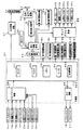
図2は、主基板(遊技制御基板)31における回路構成の一例を示すブロック図である。なお、図2は、払出制御基板37および演出制御基板80等も示されている。主基板31には、プログラムにしたがってパチンコ遊技機1を制御する遊技制御用マイクロコンピュータ(遊技制御手段に相当)560が搭載されている。遊技制御用マイクロコンピュータ560は、ゲーム制御(遊技進行制御)用のプログラム等を記憶するROM54、ワークメモリとして使用される記憶手段としてのRAM55、プログラムにしたがって制御動作を行なうCPU56およびI/Oポート部57を含む。この実施の形態では、ROM54およびRAM55は遊技制御用マイクロコンピュータ560に内蔵されている。すなわち、遊技制御用マイクロコンピュータ560は、1チップマイクロコンピュータである。1チップマイクロコンピュータには、少なくともCPU56のほかRAM55が内蔵されていればよく、ROM54は外付けであっても内蔵されていてもよい。また、I/Oポート部57は、外付けであってもよい。遊技制御用マイクロコンピュータ560には、さらに、ハードウェア乱数(ハードウェア回路が発生する乱数)を発生する乱数回路503が内蔵されている。
FIG. 2 is a block diagram showing an example of the circuit configuration of the main board (game control board) 31. FIG. 2 also shows a
また、RAM55は、その一部または全部が電源基板910において作成されるバックアップ電源によってバックアップされている不揮発性記憶手段としてのバックアップRAMである。すなわち、遊技機に対する電力供給が停止しても、所定期間(バックアップ電源としてのコンデンサが放電してバックアップ電源が電力供給不能になるまで)は、RAM55の一部または全部の内容は保存される。特に、少なくとも、遊技状態すなわち遊技制御手段の制御状態に応じたデータ(特別図柄プロセスフラグ等)と未払出賞球数を示すデータは、バックアップRAMに保存される。遊技制御手段の制御状態に応じたデータとは、停電等が生じた後に復旧した場合に、そのデータに基づいて、制御状態を停電等の発生前に復旧させるために必要なデータである。また、制御状態に応じたデータと未払出賞球数を示すデータとを遊技の進行状態を示すデータと定義する。なお、この実施の形態では、RAM55の全部が、電源バックアップされているとする。
The
なお、遊技制御用マイクロコンピュータ560においてCPU56がROM54に格納されているプログラムにしたがって制御を実行するので、以下、遊技制御用マイクロコンピュータ560(またはCPU56)が実行する(または、処理を行なう)ということは、具体的には、CPU56がプログラムにしたがって制御を実行することである。このことは、主基板31以外の他の基板に搭載されているマイクロコンピュータについても同様である。
In the
乱数回路503は、特別図柄の変動表示の表示結果により大当りとするか否か判定するための判定用の乱数を発生するために用いられるハードウェア回路である。乱数回路503は、初期値(たとえば、0)と上限値(たとえば、65535)とが設定された数値範囲内で、数値データを、設定された更新規則にしたがって更新し、ランダムなタイミングで発生する始動入賞時が数値データの読出(抽出)時であることに基づいて、読出される数値データが乱数値となる乱数発生機能を有する。 The random number circuit 503 is a hardware circuit that is used to generate a random number for determination to determine whether or not to make a big hit based on the display result of the special symbol variation display. The random number circuit 503 updates the numerical data according to the set update rule within a numerical range in which an initial value (for example, 0) and an upper limit value (for example, 65535) are set, and generates the random data at random timing. Based on the fact that the starting winning time is the time of reading (extracting) the numerical data, it has a random number generation function in which the read numerical data becomes a random value.
乱数回路503は、数値データの更新範囲の選択設定機能(初期値の選択設定機能、および、上限値の選択設定機能)、数値データの更新規則の選択設定機能、および数値データの更新規則の選択切換え機能等の各種の機能を有する。このような機能によって、生成する乱数のランダム性を向上させることができる。 The random number circuit 503 includes a numeric data update range selection setting function (initial value selection setting function and upper limit value selection setting function), numeric data update rule selection setting function, and numeric data update rule selection. It has various functions such as a switching function. With such a function, the randomness of the generated random numbers can be improved.
また、遊技制御用マイクロコンピュータ560は、乱数回路503が更新する数値データの初期値を設定する機能を有している。たとえば、遊技制御用マイクロコンピュータ560は、ROM54等の所定の記憶領域に記憶された遊技制御用マイクロコンピュータ560のIDナンバ(遊技制御用マイクロコンピュータ560の各製品ごとに異なる数値で付与されたIDナンバ)を用いて所定の演算を行なって得られた数値データを、乱数回路503が更新する数値データの初期値として設定する。そのような処理を行なうことによって、乱数回路503が発生する乱数のランダム性をより向上させることができる。
Further, the
また、ゲートスイッチ32a、始動口スイッチ13a、カウントスイッチ23、入賞口スイッチ29a,30a,33a,39aからの検出信号を遊技制御用マイクロコンピュータ560に与える入力ドライバ回路58も主基板31に搭載されている。また、可変入賞球装置15を開閉するソレノイド16、および大入賞口を形成する特別可変入賞球装置20を開閉するソレノイド21を遊技制御用マイクロコンピュータ560からの指令にしたがって駆動する出力回路59も主基板31に搭載されている。
Further, an
また、遊技制御用マイクロコンピュータ560は、特別図柄を変動表示する第1特別図柄表示器8a、第2特別図柄表示器8b、普通図柄を変動表示する普通図柄表示器10、第1特別図柄保留記憶表示器18a、第2特別図柄保留記憶表示器18bおよび普通図柄保留記憶表示器41の表示制御を行なう。
Further, the
なお、大当り遊技状態の発生を示す大当り情報等の情報出力信号をホールコンピュータ等の外部装置に対して出力する情報出力回路(図示せず)も主基板31に搭載されている。
An information output circuit (not shown) that outputs an information output signal such as jackpot information indicating the occurrence of a jackpot gaming state to an external device such as a hall computer is also mounted on the
この実施の形態では、演出制御基板80に搭載されている演出制御手段(後述する演出制御用マイクロコンピュータ100)が、中継基板77を介して遊技制御用マイクロコンピュータ560から演出内容を指示する演出制御コマンドを受信し、飾り図柄を変動表示する第1飾り図柄表示器9aおよび第2飾り図柄表示器9bの表面制御と、演出図柄を変動表示する演出表示装置9の表示制御とを行なう。また、演出制御基板80に搭載されている演出制御手段は、操作ボタン30からの操作検出信号が入力され、その信号に応じて、後述する予告演出等の各種演出を行なう。
In this embodiment, effect control means (
また、演出制御基板80に搭載されている演出制御手段が、ランプドライバ基板35を介して、遊技盤に設けられている装飾LED25、および枠側に設けられている枠LED28の表示制御を行なうとともに、音声出力基板70を介してスピーカ27からの音出力の制御を行なう。
The effect control means mounted on the
図3は、中継基板77、演出制御基板80、ランプドライバ基板35および音声出力基板70の回路構成例を示すブロック図である。なお、図3に示す例では、ランプドライバ基板35および音声出力基板70には、マイクロコンピュータは搭載されていないが、マイクロコンピュータを搭載してもよい。また、ランプドライバ基板35および音声出力基板70を設けずに、演出制御に関して演出制御基板80のみを設けてもよい。
FIG. 3 is a block diagram illustrating a circuit configuration example of the
演出制御基板80は、演出制御用CPU101、および演出図柄プロセスフラグ等の演出に関する情報を記憶するRAMを含む演出制御用マイクロコンピュータ100を搭載している。なお、RAMは外付けであってもよい。この実施の形態では、演出制御用マイクロコンピュータ100におけるRAMは電源バックアップされていない。演出制御基板80において、演出制御用CPU101は、内蔵または外付けのROM(図示せず)に格納されたプログラムにしたがって動作し、中継基板77を介して入力される主基板31からの取込信号(演出制御INT信号)に応じて、入力ドライバ102および入力ポート103を介して演出制御コマンドを受信する。また、演出制御用CPU101は、演出制御コマンドに基づいて、VDP(ビデオディスプレイプロセッサ)109に演出表示装置9の表示制御を行なわせる。
The
また、操作ボタン30からの操作信号が、入力ポート107を介して演出制御用マイクロコンピュータ100に入力される。演出制御用マイクロコンピュータ100は、後述するように、操作ボタン30からの操作信号に基づいて、たとえば予告演出等の遊技の演出を行なう。
An operation signal from the
この実施の形態では、演出制御用マイクロコンピュータ100と共動して演出表示装置9の表示制御を行なうVDP109が演出制御基板80に搭載されている。VDP109は、演出制御用マイクロコンピュータ100とは独立したアドレス空間を有し、そこにVRAMをマッピングする。VRAMは、画像データを展開するためのバッファメモリである。そして、VDP109は、VRAM内の画像データをフレームメモリを介して演出表示装置9に出力する。
In this embodiment, a
演出制御用CPU101は、受信した演出制御コマンドにしたがってCGROM(図示せず)から必要なデータを読出すための指令をVDP109に出力する。CGROMは、演出表示装置9に表示されるキャラクタ画像データや動画像データ、具体的には、人物、文字、図形や記号等(演出図柄を含む)、および背景画像のデータを予め格納しておくためのROMである。VDP109は、演出制御用CPU101の指令に応じて、CGROMから画像データを読出す。そして、VDP109は、読出した画像データに基づいて表示制御を実行する。
The
演出制御コマンドおよび演出制御INT信号は、演出制御基板80において、まず、入力ドライバ102に入力する。入力ドライバ102は、中継基板77から入力された信号を演出制御基板80の内部に向かう方向にしか通過させない(演出制御基板80の内部から中継基板77への方向には信号を通過させない)信号方向規制手段としての単方向性回路でもある。
The effect control command and the effect control INT signal are first input to the
中継基板77には、主基板31から入力された信号を演出制御基板80に向かう方向にしか通過させない(演出制御基板80から中継基板77への方向には信号を通過させない)信号方向規制手段としての単方向性回路74が搭載されている。単方向性回路として、たとえばダイオードやトランジスタが使用される。図3には、ダイオードが例示されている。また、単方向性回路は、各信号毎に設けられる。さらに、単方向性回路である出力ポート571を介して主基板31から演出制御コマンドおよび演出制御INT信号が出力されるので、中継基板77から主基板31の内部に向かう信号が規制される。すなわち、中継基板77からの信号は主基板31の内部(遊技制御用マイクロコンピュータ560側)に入り込まない。なお、出力ポート571は、図2に示されたI/Oポート部57の一部である。また、出力ポート571の外側(中継基板77側)に、さらに、単方向性回路である信号ドライバ回路が設けられていてもよい。
As a signal direction regulating means, the signal inputted from the
また、演出制御用CPU101は、出力ポート106を介して、可動部材78を動作させるためにモータ86を駆動する。また、演出制御用CPU101は、上演出LED85a、中演出LED85bおよび下演出LED85cの近傍に設けられ、各LEDの取付部分を信号させる振動モータ87a,87b,87cを出力ポート106を介して駆動する。振動モータ87aは、上演出LED85aを振動させる。振動モータ87bは、中演出LED85bを振動させ、振動モータ87cは下演出LED85cを振動させる。
The
さらに、演出制御用CPU101は、出力ポート105を介してランプドライバ基板35に対してLEDを駆動する信号を出力する。また、演出制御用CPU101は、出力ポート104を介して音声出力基板70に対して音番号データを出力する。
Further, the
ランプドライバ基板35において、LEDを駆動する信号は、入力ドライバ351を介してLEDドライバ352に入力される。LEDドライバ352は、LEDを駆動する信号に基づいて枠LED28等の枠側に設けられている発光体に電流を供給する。また、遊技盤側に設けられている装飾LED25、上演出LED85a、中演出LED85bおよび下演出LED85cに電流を供給する。
In the
音声出力基板70において、音番号データは、入力ドライバ702を介して音声合成用IC703に入力される。音声合成用IC703は、音番号データに応じた音声や効果音を発生し増幅回路705に出力する。増幅回路705は、音声合成用IC703の出力レベルを、ボリューム706で設定されている音量に応じたレベルに増幅した音声信号をスピーカ27に出力する。音声データROM704には、音番号データに応じた制御データが格納されている。音番号データに応じた制御データは、所定期間(たとえば演出図柄の変動期間)における効果音または音声の出力態様を時系列的に示すデータの集まりである。
In the
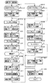
次に、遊技機の動作について説明する。図4は、主基板31における遊技制御用マイクロコンピュータ560が実行するメイン処理を示すフローチャートである。遊技機に対して電源が投入され電力供給が開始されると、リセット信号が入力されるリセット端子の入力レベルがハイレベルになる。そして、遊技制御用マイクロコンピュータ560(具体的には、CPU56)は、プログラムの内容が正当か否か確認するための処理であるセキュリティチェック処理を実行した後、ステップS(以下、単にSと呼ぶ)1以降のメイン処理を開始する。メイン処理において、CPU56は、まず、必要な初期設定を行なう。
Next, the operation of the gaming machine will be described. FIG. 4 is a flowchart showing a main process executed by the
初期設定処理において、CPU56は、まず、割込禁止に設定する(S1)。次に、割込モードを割込モード2に設定し(S2)、スタックポインタにスタックポインタ指定アドレスを設定する(S3)。そして、内蔵デバイスの初期化(内蔵デバイス(内蔵周辺回路)であるCTC(カウンタ/タイマ)およびPIO(パラレル入出力ポート)の初期化等)を行なった後(S4)、RAM55をアクセス可能状態に設定する(S5)。なお、割込モード2は、CPU56が内蔵する特定レジスタ(Iレジスタ)の値(1バイト)と内蔵デバイスが出力する割込ベクタ(1バイト:最下位ビット0)とから合成されるアドレスが、割込番地を示すモードである。
In the initial setting process, the
次いで、CPU56は、入力ポートを介して入力されるクリアスイッチ(たとえば、電源基板に搭載されている。)の出力信号の状態を確認する(S6)。その確認においてオンを検出した場合には、CPU56は、通常の初期化処理を実行する(S10〜S15)。
Next, the
クリアスイッチがオンの状態でない場合には、遊技機への電力供給が停止したときにバックアップRAM領域のデータ保護処理(たとえばパリティデータの付加等の電力供給停止時処理)が行なわれたか否か確認する(S7)。そのような保護処理が行なわれていないことを確認したら、CPU56は初期化処理を実行する。バックアップRAM領域にバックアップデータがあるか否かは、たとえば、電力供給停止時処理においてバックアップRAM領域に設定されるバックアップフラグの状態によって確認される。
If the clear switch is not on, check whether data protection processing for the backup RAM area (for example, power supply stop processing such as addition of parity data) was performed when power supply to the gaming machine was stopped (S7). If it is confirmed that such a protection process has not been performed, the
電力供給停止時処理が行なわれたことを確認したら、CPU56は、バックアップRAM領域のデータチェックを行なう(S8)。この実施の形態では、データチェックとしてパリティチェックを行なう。よって、S8では、算出したチェックサムと、電力供給停止時処理で同一の処理によって算出され保存されているチェックサムとを比較する。不測の停電等の電力供給停止が生じた後に復旧した場合には、バックアップRAM領域のデータは保存されているはずであるから、チェック結果(比較結果)は正常(一致)になる。チェック結果が正常でないということは、バックアップRAM領域のデータが、電力供給停止時のデータとは異なっていることを意味する。そのような場合には、内部状態を電力供給停止時の状態に戻すことができないので、電力供給の停止からの復旧時でない電源投入時に実行される初期化処理を実行する。
If it is confirmed that the power supply stop process has been performed, the
チェック結果が正常であれば、CPU56は、遊技制御手段の内部状態と演出制御手段等の電気部品制御手段の制御状態を電力供給停止時の状態に戻すための遊技状態復旧処理(S41〜S43の処理)を行なう。具体的には、ROM54に格納されているバックアップ時設定テーブルの先頭アドレスをポインタに設定し(S41)、バックアップ時設定テーブルの内容を順次作業領域(RAM55内の領域)に設定する(S42)。作業領域はバックアップ電源によって電源バックアップされている。バックアップ時設定テーブルには、作業領域のうち初期化してもよい領域についての初期化データが設定されている。S41およびS42の処理によって、作業領域のうち初期化してはならない部分については、保存されていた内容がそのまま残る。初期化してはならない部分とは、たとえば、電力供給停止前の遊技状態を示すデータ(特別図柄プロセスフラグ、確変フラグ、時短フラグ等)、出力ポートの出力状態が保存されている領域(出力ポートバッファ)、未払出賞球数を示すデータが設定されている部分等である。
If the check result is normal, the
また、CPU56は、電力供給復旧時の初期化コマンドとしての停電復旧指定コマンド(停電復旧1指定コマンド)を演出制御基板80に送信する(S43)。そして、S14に移行する。
Further, the
なお、この実施の形態では、バックアップフラグとチェックデータとの双方を用いてバックアップRAM領域のデータが保存されているか否か確認しているが、いずれか一方のみを用いてもよい。すなわち、バックアップフラグとチェックデータとのいずれかを、遊技状態復旧処理を実行するための契機としてもよい。 In this embodiment, it is confirmed whether the data in the backup RAM area is stored using both the backup flag and the check data. However, only one of them may be used. That is, either the backup flag or the check data may be used as an opportunity for executing the game state restoration process.
初期化処理では、CPU56は、まず、RAMクリア処理を行なう(S10)。なお、RAMクリア処理によって、所定のデータ(たとえば大当り判定用乱数を生成するためのカウンタのカウント値のデータ)は0に初期化されるが、任意の値または予め決められている値に初期化するようにしてもよい。また、RAM55の全領域を初期化せず、所定のデータ(たとえば大当り判定用乱数を生成するためのカウンタのカウント値のデータ)をそのままにしてもよい。また、ROM54に格納されている初期化時設定テーブルの先頭アドレスをポインタに設定し(S11)、初期化時設定テーブルの内容を順次RAM55における作業領域に設定する(S12)。
In the initialization process, the
S11およびS12の処理によって、特別図柄プロセスフラグ等制御状態に応じて選択的に処理を行なうためのフラグに初期値が設定される。 By the processing of S11 and S12, an initial value is set to a flag for selectively performing processing according to a control state such as a special symbol process flag.
また、CPU56は、サブ基板(主基板31以外のマイクロコンピュータが搭載された基板。)を初期化するための初期化指定コマンド(遊技制御用マイクロコンピュータ560が初期化処理を実行したことを示すコマンドでもある。)を演出制御基板80に送信する(S13)。たとえば、演出制御基板80に搭載されている演出制御用マイクロコンピュータ100は、初期化指定コマンドを受信すると、演出表示装置9において、遊技機の制御の初期化がなされたことを報知するための画面表示、すなわち初期化報知を行なう。なお、初期化処理において、CPU56は、客待ちデモンストレーション指定(デモ指定)コマンドも送信する。
Further, the
また、CPU56は、乱数回路503を初期設定する乱数回路設定処理を実行する(S14)。CPU56は、たとえば、乱数回路設定プログラムにしたがって処理を実行することによって、乱数回路503にランダムRの値を更新させるための設定を行なう。
Further, the
そして、CPU56は、所定時間(たとえば2ms)毎に定期的にタイマ割込がかかるように遊技制御用マイクロコンピュータ560に内蔵されているCTCのレジスタの設定を行なう(S15)。すなわち、初期値としてたとえば2msに相当する値が所定のレジスタ(時間定数レジスタ)に設定される。この実施の形態では、2ms毎に定期的にタイマ割込がかかるとする。
Then, the
初期化処理の実行(S10〜S15)が完了すると、CPU56は、メイン処理で、表示用乱数更新処理(S17)および初期値用乱数更新処理(S18)を繰返し実行する。表示用乱数更新処理および初期値用乱数更新処理を実行するときには割込禁止状態に設定し(S16)、表示用乱数更新処理および初期値用乱数更新処理の実行が終了すると割込許可状態に設定する(S19)。この実施の形態では、表示用乱数とは、変動パターン等を決定するための乱数であり、表示用乱数更新処理とは、表示用乱数を発生するためのカウンタのカウント値を更新する処理である。また、初期値用乱数更新処理とは、初期値用乱数を発生するためのカウンタのカウント値を更新する処理である。この実施の形態では、初期値用乱数とは、普通図柄の当りとするか否か決定するための乱数を発生するためのカウンタ(普通図柄当り判定用乱数発生カウンタ)等のカウント値の初期値を決定するための乱数である。後述する遊技の進行を制御する遊技制御処理(遊技制御用マイクロコンピュータ560が、遊技機に設けられている変動表示装置、可変入賞球装置、球払出装置等の遊技用の装置を、自身で制御する処理、または他のマイクロコンピュータに制御させるために指令信号を送信する処理、遊技装置制御処理ともいう)において、普通図柄当り判定用乱数発生カウンタ等のカウント値が1周(乱数の取りうる値の最小値から最大値までの間の数値の個数分歩進したこと)すると、そのカウンタに初期値が設定される。
When the execution of the initialization process (S10 to S15) is completed, the
なお、本実施の形態における遊技制御用マイクロコンピュータ560においては、大当り判定用乱数発生カウンタとして、内蔵されている乱数回路503によるハードウェア乱数を用いる。したがって、大当り判定用乱数については、このような初期値の設定は行なわれない。ただし、遊技制御用マイクロコンピュータ560が大当り判定用乱数発生カウンタとしてソフトウェア乱数を用いる場合には、当該カウンタについて、前述のような初期値用乱数を用いた初期値の設定を行なうようにしてもよい。このようにした場合には、大当り判定用乱数発生カウンタが最大値まで歩進した後の初期値がランダムな値となるので、大当りの判定値と同じ乱数値を不正に狙って取出して大当りを発生させる不正行為が行なわれにくくなるようにすることができる。
In the
タイマ割込が発生すると、CPU56は、図5に示すS20〜S34のタイマ割込処理を実行する。タイマ割込処理において、まず、電源断信号が出力されたか否か(オン状態になったか否か)を検出する電源断検出処理を実行する(S20)。電源断信号は、たとえば電源基板に搭載されている電源監視回路920が、遊技機に供給される電源の電圧の低下を検出した場合に出力する。そして、電源断検出処理において、CPU56は、電源断信号が出力されたことを検出したら、必要なデータをバックアップRAM領域に保存するための電力供給停止時処理を実行する。次いで、入力ドライバ回路58を介して、ゲートスイッチ32a、第1始動口スイッチ13a、第2始動口スイッチ14a、カウントスイッチ23、および入賞口スイッチ29a,30a,33a,39aの検出信号を入力し、それらの状態判定を行なうスイッチ処理を実行する(S21)。
When the timer interrupt occurs, the
次に、CPU56は、第1特別図柄表示器8a、第2特別図柄表示器8b、普通図柄表示器10、第1特別図柄保留記憶表示器18a、第2特別図柄保留記憶表示器18b、普通図柄保留記憶表示器41の表示制御を行なう表示制御処理を実行する(S22)。第1特別図柄表示器8a、第2特別図柄表示器8bおよび普通図柄表示器10については、S32,S33で設定される出力バッファの内容に応じて各表示器に対して駆動信号を出力する制御を実行する。
Next, the
また、遊技制御に用いられる普通当り図柄決定用の乱数等の各判定用乱数を生成するための各カウンタのカウント値を更新する判定用乱数更新処理を行なう(S23)。CPU56は、さらに、初期値用乱数および表示用乱数を生成するためのカウンタのカウント値を更新する初期値用乱数更新処理(S24)および表示用乱数更新処理(S25)を実行する。
Also, a determination random number update process is performed to update the count value of each counter for generating each determination random number such as a random number for determining a normal winning symbol used for game control (S23). The
さらに、CPU56は、特別図柄プロセス処理を行なう(S26)。特別図柄プロセス処理では、第1特別図柄表示器8a、第2特別図柄表示器8bおよび大入賞口を所定の順序で制御するための特別図柄プロセスフラグにしたがって該当する処理を実行する。CPU56は、特別図柄プロセスフラグの値を、遊技状態に応じて更新する。
Further, the
次いで、普通図柄プロセス処理を行なう(S27)。普通図柄プロセス処理では、CPU56は、普通図柄表示器10の表示状態を所定の順序で制御するための普通図柄プロセスフラグにしたがって該当する処理を実行する。CPU56は、普通図柄プロセスフラグの値を、遊技状態に応じて更新する。
Next, the normal symbol process is performed (S27). In the normal symbol process, the
また、CPU56は、演出制御用マイクロコンピュータ100に演出制御コマンドを送出する演出制御コマンド制御処理を行なう(S28)。
Further, the
さらに、CPU56は、たとえばホール管理用コンピュータに供給される大当り情報、始動情報、確率変動情報等のデータを出力する情報出力処理を行なう(S29)。
Further, the
また、CPU56は、第1始動口スイッチ13a、第2始動口スイッチ14a、カウントスイッチ23および入賞口スイッチ29a,30a,33a,39aの検出信号に基づく賞球個数の設定等を行なう賞球処理を実行する(S30)。具体的にCPU56は、第1始動口スイッチ13a、第2始動口スイッチ14a、カウントスイッチ23および入賞口スイッチ29a,30a,33a,39aのいずれかがオンしたことに基づく入賞検出に応じて、払出制御基板37に搭載されている払出制御用マイクロコンピュータに賞球個数を示す払出制御コマンド(賞球個数信号)を出力する。払出制御用マイクロコンピュータは、賞球個数を示す払出制御コマンドに応じて球払出装置97を駆動する。
Further, the
この実施の形態では、出力ポートの出力状態に対応したRAM領域(出力ポートバッファ)が設けられているのであるが、CPU56は、出力ポートの出力状態に対応したRAM領域におけるソレノイドのオン/オフに関する内容を出力ポートに出力する出力処理を実行する(S31)。
In this embodiment, a RAM area (output port buffer) corresponding to the output state of the output port is provided. However, the
また、CPU56は、特別図柄プロセスフラグの値に応じて特別図柄の演出表示を行なうための特別図柄表示制御データを特別図柄表示制御データ設定用の出力バッファに設定する特別図柄表示制御処理を行なう(S32)。CPU56は、たとえば、特別図柄プロセス処理でセットされる開始フラグがセットされると終了フラグがセットされるまで、変動速度が1コマ/0.2秒であれば、0.2秒が経過する毎に、出力バッファに設定される表示制御データの値を+1する。また、CPU56は、出力バッファに設定された表示制御データに応じて、S22において駆動信号を出力することによって、第1特別図柄表示器8aおよび第2特別図柄表示器8bにおける第1特別図柄および第2特別図柄の変動表示を実行する。
Further, the
さらに、CPU56は、普通図柄プロセスフラグの値に応じて普通図柄の演出表示を行なうための普通図柄表示制御データを普通図柄表示制御データ設定用の出力バッファに設定する普通図柄表示制御処理を行なう(S33)。CPU56は、たとえば、普通図柄の変動に関する開始フラグがセットされると終了フラグがセットされるまで、普通図柄の変動速度が0.2秒ごとに表示状態(「○」および「×」)を切替えるような速度であれば、0.2秒が経過する毎に、出力バッファに設定される表示制御データの値(たとえば、「○」を示す1と「×」を示す0)を切替える。また、CPU56は、出力バッファに設定された表示制御データに応じて、S22において駆動信号を出力することによって、普通図柄表示器10における普通図柄の演出表示を実行する。
Further, the
その後、割込許可状態に設定し(S34)、処理を終了する。
以上の制御によって、この実施の形態では、遊技制御処理は2ms毎に起動されることになる。なお、遊技制御処理は、タイマ割込処理におけるS21〜S33(S29を除く。)の処理に相当する。また、この実施の形態では、タイマ割込処理で遊技制御処理が実行されているが、タイマ割込処理ではたとえば割込が発生したことを示すフラグのセットのみがなされ、遊技制御処理はメイン処理において実行されるようにしてもよい。
Thereafter, the interrupt permission state is set (S34), and the process ends.
With the above control, in this embodiment, the game control process is started every 2 ms. The game control process corresponds to the processes of S21 to S33 (excluding S29) in the timer interrupt process. In this embodiment, the game control process is executed by the timer interrupt process. However, in the timer interrupt process, for example, only a flag indicating that an interrupt has occurred is set, and the game control process is performed by the main process. May be executed.
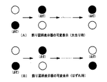
次に、この実施の形態の遊技機における演出表示装置9で実行される擬似連の表示演出を説明する。以下に示すパターンa〜パターンdのそれぞれは、擬似連の表示が実行されるときに、再変動が行なわれることを、演出表示装置9、上演出LED85a、中演出LED85b、下演出LED85c、および、可動部材78のような報知手段を用いて所定の報知態様で報知する報知演出を含む演出パターンを示している。
Next, a pseudo-continuous display effect executed by the
図6は、擬似連の表示演出例を示す説明図である。図6(A)に示すパターンaは、それぞれの再変動(初回変動も含む。)の期間中に、上演出LED85a、中演出LED85bおよび下演出LED85cのうち点灯されるものが1つずつ増えていくように制御される。なお、仮停止期間において、LED(上演出LED85a、中演出LED85b、下演出LED85c)はすべて消灯状態であってもよい。また、再変動(初回変動も含む。)の期間中に、LEDは点滅するように制御されてもよいし、表示色が変わるように制御されてもよいし、点灯されるものが1つずつ増えていくように制御されるのではなく上演出LED85a、中演出LED85bおよび下演出LED85cのうちで点灯するものが変わるように制御されるようにしてもよい。また、図6(A)には、演出図柄の1回の変動中に2回の仮停止期間が設けられ、3回の再変動(初回変動も含む。)が行なわれる例が示されている。しかし、これに限らず、仮停止の回数は、1回の場合もあってもよいし、3回以上であってもよい。また、それぞれの再変動(初回変動も含む。)A1,A2,A3を、第1再変動演出態様の再変動演出ということがある。
FIG. 6 is an explanatory diagram illustrating an example of a pseudo-continuous display effect. In the pattern a shown in FIG. 6A, one of the
なお、擬似連の初回変動において使用される演出態様(図6に示す例では、A1、B1、C1、D1)は、擬似連を伴わない変動パターン(一例として、スーパーリーチの変動パターンやノーマルリーチの変動パターン)における一部の演出態様としても用いられるようにしてもよい。 It should be noted that the production mode (A1, B1, C1, D1 in the example shown in FIG. 6) used in the initial fluctuation of the pseudo-continuous is a fluctuation pattern that does not involve the pseudo-continuous (for example, a super-reach fluctuation pattern or a normal reach fluctuation pattern). (Fluctuation pattern) may be used as part of the production mode.
図6(B)に示すパターンbは、それぞれの再変動(初回変動も含む。)の期間中に、可動部材78が動作する。なお、仮停止期間において、可動部材78は停止状態であってもよい。また、図6(B)には、演出図柄の1回の変動中に2回の仮停止期間が設けられ、3回の再変動(初回変動も含む。)が行なわれる例が示されている。しかし、これに限らず、仮停止の回数は、1回の場合もあってもよいし、3回以上であってもよい。また、それぞれの再変動(初回変動も含む。)B1,B2,B3を、第2再変動演出態様(I)の再変動演出ということがある。
In the pattern b shown in FIG. 6B, the
図6(C)に示すパターンcは、それぞれの再変動(初回変動も含む。)の期間中に、演出表示装置9において特定のキャラクタ画像が表示される。なお、仮停止期間では、特定のキャラクタ画像が表示されないようにしてもよい。また、図6(C)には、演出図柄の1回の変動中に2回の仮停止期間が設けられ、3回の再変動(初回変動も含む。)が行なわれる例が示されている。しかし、これに限らず、仮停止の回数は、1回の場合もあってもよいし、3回以上であってもよい。また、それぞれの再変動(初回変動も含む。)C1,C2,C3を、第2再変動演出態様(II)の再変動演出ということがある。
In the pattern c shown in FIG. 6C, a specific character image is displayed on the
図6(D)に示すパターンdは、複数の再変動(初回変動も含む。)の期間の1つ以上の期間において、第1再変動演出態様と第2再変動演出態様(第2再変動演出態様(I)もしくは第2再変動演出態様(II)、または第2再変動演出態様(I)と第2再変動演出態様(II)の双方)で演出が実行されるパターンである。なお、仮停止期間では、第1再変動演出態様および第2再変動演出態様の演出が実行されないようにしてもよい。また、図6(D)には、演出図柄の1回の変動中に2回の仮停止期間が設けられ、3回の再変動(初回変動も含む。)が行なわれる例が示されている。しかし、これに限らず、仮停止の回数は、1回の場合もあってもよいし、3回以上であってもよい。また、それぞれの再変動(初回変動も含む。)D1,D2,D3を、第3再変動演出態様の再変動演出ということがある。 The pattern d shown in FIG. 6D has a first re-variation effect mode and a second re-change effect mode (second re-variation) in one or more periods of a plurality of re-changes (including initial changes). This is a pattern in which an effect is executed in the effect mode (I) or the second re-variation effect mode (II), or in the second re-change effect mode (I) and the second re-change effect mode (II)). In the temporary stop period, the effects of the first re-change effect mode and the second re-change effect mode may not be executed. FIG. 6D shows an example in which two temporary stop periods are provided during one fluctuation of the effect design and three re-variations (including the first fluctuation) are performed. . However, the present invention is not limited to this, and the number of temporary stops may be one or may be three or more. Each re-variation (including initial variation) D1, D2, and D3 may be referred to as a re-variation effect in the third re-variation effect mode.
なお、図6(D)において、「2つ点灯」のボックスが破線で示されているのは、その演出が実行される場合もあり、実行されない場合もあることを示す。実行されない場合には、初回変動においてLED(上演出LED85a、中演出LED85bまたは下演出LED85c)を用いた演出が実行され、次に実行される再変動において、可動部材78を用いた演出が実行されるが、LEDを用いた演出は実行されないことを示す。
In FIG. 6D, the “two lit” box is indicated by a broken line indicates that the effect may or may not be executed. If not executed, an effect using the LED (
図7は、演出表示装置9におけるパターンaの再変動演出の具体例を示す説明図である。パターンaの再変動演出では、図7(A)に示す状態(左中右の演出図柄が停止している状態)から演出図柄の変動が開始されてから、所定期間演出図柄の変動が実行され(図7(B)参照)、所定期間が経過すると左中右の演出図柄が仮停止する(図7(C)参照)。そして、図7に示す例では、所定の仮停止期間が経過すると、左中右の演出図柄が再変動し(図7(D)参照)、所定の再変動期間が経過するとリーチとなる(図7(E)参照)。その後、左中右の演出図柄は最終停止(確定)する。図7に示す例では、初回変動の期間において、下演出LED85cが点灯し、初回変動に続く再変動期間において、中演出LED85bおよび下演出LED85cが点灯する。なお、図7に示す例は、1回の仮停止が行なわれる場合の例である。また、図7(A)〜(C)の期間が、図6(A)に示されたA1の期間に相当し、図7(D)〜(E)の期間が、図6(A)に示されたA2の期間に相当する。ただし、図7に示す例では、仮停止が1回の例であって、A2の期間が終了するとリーチとなる。その後、リーチ演出が実行された後、左中右の演出図柄は最終停止(確定)する。なお、ここでは、再変動演出が終了するときにリーチになると説明したが、再変動演出が終了するときに、演出図柄はリーチにならず最終停止する場合もある。
FIG. 7 is an explanatory diagram showing a specific example of the re-variation effect of the pattern a in the
図7において、上演出LED85a、中演出LED85bおよび下演出LED85cのうち黒で表示されているLEDは点灯状態であるLEDである。また、点灯状態であるLEDは、振動モータ87a,87b,87c(図3参照)によって振動させられる。また、図7において、下向き矢印は、演出図柄が変動表示されている(変動している)ことを示す。なお、そのことは、図8〜図11においても同様である。
In FIG. 7, among the
なお、図7においては、初回変動の期間において、(B)のタイミングのように全図柄が変動中に下演出LED85cが点灯する例を示した。しかし、これに限らず、初回変動の期間において、たとえば(C)のタイミングのような仮停止時および(D)のタイミングのような再変動開始時に下演出LED85cが点灯するようにしてもよい。つまり、擬似連における上演出LEDの点灯タイミングとしては、各仮停止時であってもよく、各再変動時であってもよい。
Note that FIG. 7 shows an example in which the
図8は、演出表示装置9におけるパターンbの再変動演出の具体例を示す説明図である。パターンbの再変動演出では、図8(A)に示す状態(左中右の演出図柄が停止している状態)から演出図柄の変動が開始されてから、所定期間演出図柄の変動が実行され(図8(B),(C)参照)、所定期間が経過すると左中右の演出図柄が仮停止する(図8(D)参照)。そして、所定の仮停止期間が経過すると、左中右の演出図柄が再変動し(図8(E)参照)、所定の再変動期間が経過すると、左右の演出図柄が停止してリーチとなる(図8(F)参照)。その後、リーチ演出が実行された後、左中右の演出図柄が最終停止(確定)する。図8に示す例では、初回変動の期間において、可動部材78が動作(演出表示装置9の表示画面に進入した後、元の位置(表示画面外)に戻るように動作)し、初回変動に続く再変動期間においても、可動部材78が動作する。なお、図8に示す例は、1回の仮停止が行なわれる場合の例である。また、図8(A)〜(D)の期間が、図6(B)に示されたB1の期間に相当し、図8(E)〜(F)の期間が、図6(B)に示されたB2の期間に相当する。ただし、図8に示す例では、仮停止が1回の例であって、B2の期間が終了するとリーチとなる。その後、リーチ演出が実行された後、左中右の演出図柄は最終停止(確定)する。なお、ここでは、再変動演出が終了するときにリーチになると説明したが、再変動演出が終了するときに、演出図柄はリーチにならず最終停止する場合もある。
FIG. 8 is an explanatory diagram showing a specific example of the re-variation effect of the pattern b in the
図9は、演出表示装置9におけるパターンcの再変動演出の具体例を示す説明図である。パターンcの再変動演出では、図9(A)に示す状態(左中右の演出図柄が停止している状態)から演出図柄の変動が開始されてから、所定期間演出図柄の変動が実行され(図9(B)参照)、所定期間が経過すると左中右の演出図柄が仮停止する(図9(C)参照)。そして、所定の仮停止期間が経過すると、左中右の演出図柄が再変動し(図9(D)参照)、所定の再変動期間が経過すると、左右の演出図柄が停止してリーチとなる(図9(E)参照)。その後、リーチ演出が実行された後、左中右の演出図柄が最終停止(確定)する。図9に示す例では、初回変動の期間において、特定のキャラクタ画像79aが演出表示装置9において表示され、初回変動に続く再変動期間において、特定のキャラクタ画像79b(特定のキャラクタ画像79aと関連する画像であって、演出が発展したかのように遊技者に感じさせる画像)が演出表示装置9において表示される。なお、図9に示す例は、1回の仮停止が行なわれる場合の例である。また、図9(A)〜(C)の期間が、図6(C)に示されたC1の期間に相当し、図9(D)〜(E)の期間が、図6(C)に示されたC2の期間に相当する。ただし、図9に示す例では、仮停止が1回の例であって、C2の期間が終了するとリーチとなる。その後、リーチ演出が実行された後、左中右の演出図柄は最終停止(確定)する。なお、ここでは、再変動演出が終了するときにリーチになると説明したが、再変動演出が終了するときに、演出図柄はリーチにならず最終停止する場合もある。
FIG. 9 is an explanatory diagram showing a specific example of the re-variation effect of the pattern c in the
図10および図11は、演出表示装置9におけるパターンdの再変動演出の具体例を示す説明図である。パターンaの再変動演出では、図10(A)に示す状態(左中右の演出図柄が停止している状態)から演出図柄の変動が開始されてから、所定期間演出図柄の変動が実行され(図10(B)参照)、所定期間が経過すると左中右の演出図柄が仮停止する(図10(C)参照)。そして、所定の仮停止期間が経過すると、左中右の演出図柄が再変動し(図10(D),(E)参照)、所定の再変動期間が経過すると、左中右の演出図柄が再び仮停止する(図10(F)参照)。そして、所定の仮停止期間が経過すると、左中右の演出図柄が再変動し(図11(G)参照)、所定の再変動期間が経過すると、リーチとなる(図11(H)参照)。その後、リーチ演出が実行された後、左中右の演出図柄は最終停止(確定)する。図10および図11に示す例では、初回変動の期間において、下演出LED85cが点灯し、初回変動に続く再変動期間において、中演出LED85bおよび下演出LED85cが点灯するとともに、可動部材78が動作する。また、続く再変動期間において、可動部材78が動作するとともに、特定のキャラクタ画像79c(特定のキャラクタ画像79a,79bと関連する画像であって、演出がさらに発展したかのように遊技者に感じさせる画像)が演出表示装置9において表示される。なお、図10および図11に示す例は、2回の仮停止が行なわれる場合の例である。また、図10(A)〜(C)の期間が、図6(D)に示されたD1の期間に相当し、図10(D)〜(F)の期間が、図6(D)に示されたD2の期間に相当する。また、図11(G)〜図11(H)の期間が、図6(D)に示されたD3の期間に相当する。
10 and 11 are explanatory diagrams showing specific examples of the re-variation effect of the pattern d in the
また、図10および図11において、上演出LED85a、中演出LED85bおよび下演出LED85cのうち黒で表示されているLEDは点灯状態であるLEDである。また、点灯状態であるLEDは、振動モータ87a,87b,87c(図3参照)によって振動させられる。
In FIGS. 10 and 11, the LED displayed in black among the
図10に例示したように、この実施の形態では、パターンaを構成する初回変動(図10(A)〜(C)参照)が実行された後、パターンbを構成する再変動(図10(D)〜(F)参照)が実行される。すなわち、第1再変動演出(たとえば、パターンaを構成する)を実行した後に第2再変動演出(たとえば、パターンbを構成する)を実行することが可能である。なお、図10に示す例では、パターンbを構成する再変動(図10(D)〜(F)参照)が実行されるときにもパターンaを構成する再変動(LEDの点灯を伴う再変動)が実行されているが、パターンbを構成する再変動(図10(D)〜(F)参照)が実行されるときに、パターンaを構成する再変動(LEDの点灯を伴う再変動)が実行されなくてもよい。また、図10(D)〜(F)に示すようなパターンaを構成する再変動とパターンbを構成する再変動とが組合わされたものを、第2再変動演出と捉えることもできる。つまり、演出の態様が異なる任意の2つの再変動演出は、第1再変動演出と第2再変動演出に相当すると捉えることができる。 As illustrated in FIG. 10, in this embodiment, after the initial variation (see FIGS. 10A to 10C) constituting the pattern a is executed, the re-variation (see FIG. D) to (F)) are executed. That is, it is possible to execute the second re-variation effect (for example, the pattern b) after executing the first re-change effect (for example, the pattern a). In the example shown in FIG. 10, the re-variation (revariation accompanied by the lighting of the LED) constituting pattern a is also performed when re-variation (see FIGS. 10D to 10F) constituting pattern b is executed. ) Is executed, but when the re-variation that constitutes the pattern b (see FIGS. 10D to 10F) is executed, the re-variation that constitutes the pattern a (re-variation accompanying the lighting of the LED) May not be executed. Moreover, what combined the re-variation which comprises the pattern a as shown to FIG.10 (D)-(F), and the re-variation which comprises the pattern b can also be regarded as a 2nd re-change effect. That is, it can be understood that any two re-variation effects having different aspects of the effect correspond to the first re-change effect and the second re-change effect.
また、パターンaを構成する再変動を第1再変動と捉え、パターンaとは異なるパターン(この例では、パターンb)を構成する再変動を第2再変動と捉え、パターンaを構成する再変動とパターンaとは異なるパターン(この例では、パターンb)を構成する再変動とが組合わされたものを第3再変動と捉えることもできる。そのように捉えた場合には、第1再変動演出または第2再変動演出を実行した後に第3再変動演出を実行することが可能であることになる。 Further, the re-variation constituting the pattern a is regarded as the first re-variation, the re-variation constituting the pattern different from the pattern a (pattern b in this example) is regarded as the second re-variation, and the re-variation constituting the pattern a is considered. A combination of the fluctuation and the re-variation constituting the pattern different from the pattern a (in this example, the pattern b) can be regarded as the third re-variation. In such a case, the third re-variation effect can be executed after the first re-change effect or the second re-change effect is executed.
なお、上記のように、図7〜図11に示された例に説明において、再変動演出が終了するときにリーチになるとしたが、再変動演出が終了したときに、演出図柄はリーチにならず最終停止する場合もある。 As described above, in the example shown in FIGS. 7 to 11, it is assumed that the reach is reached when the re-variation effect ends, but when the re-change effect ends, the effect symbol becomes reach. There may be a final stop.
また、上記の例では、識別情報(ここでは、演出図柄)の変動表示が開始されてから表示結果が導出表示されるまでに一旦非特定表示結果(大当りを想起させない演出図柄の組合せ)となる識別情報を仮停止させた後にすべての識別情報について変動表示を再度実行する再変動を1回または複数回実行する再変動表示パターンにおける複数種類の再変動演出(すなわち、再変動を報知する報知演出)として、発光体(上演出LED85a、中演出LED85bおよび下演出LED85c)、可動部材78、特定のキャラクタ画像79a,79b,79cを用いた演出態様が例示されたが、他の演出態様を用いてもよい。たとえば、スピーカ27による音声や効果音の出力の違い、演出対象物(たとえば、可動部材78)の動きの違い(動作速度の違い、動作する距離の違い、動作方向の違い等)、演出表示装置9に表示されるキャラクタ画像の動きの違い(動作速度の違い、動作する距離の違い、動作方向の違い等)によって再変動演出の演出態様を違えたり、演出表示装置9においてキャラクタ画像ではなく文字を変えたり背景画像を変えたりして、再変動演出の演出態様を違えたりするようにしてもよい。
Further, in the above example, the non-specific display result (a combination of effect symbols that does not evoke a big hit) is generated from the start of the variable display of the identification information (here, the effect symbol) until the display result is derived and displayed. A plurality of types of re-variation effects in a re-variation display pattern in which re-variation is performed once or a plurality of times after the identification information is temporarily stopped and then the variation display is performed again for all the identification information (that is, a notification effect for informing the re-variation) ), The effect form using the light emitter (
第1特別図柄表示器8aまたは第2特別図柄表示器8bにおいて、特別図柄(第1特別図柄または第2特別図柄)の変動表示が開始された後、所定時間(変動時間)が経過すると、特別図柄の変動表示結果である停止図柄を停止表示(導出表示)する。大当りにすることに決定されている場合には、特定の特別図柄(大当り図柄)が停止表示される。小当りにすることに決定されている場合には、大当り図柄とは異なる所定の特別図柄(小当り図柄)が停止表示される。はずれにすることに決定されている場合には、大当り図柄や小当り図柄以外の特別図柄が停止表示される。大当り図柄が導出表示された場合には、遊技状態が、特定遊技状態としての大当り遊技状態に制御される。また、小当り図柄が導出表示された場合には、大当り遊技状態とは異なる小当り遊技状態に制御される。この実施の形態では、一例として、「1」、「3」、「7」を示す数字を大当り図柄とし、「5」を示す数字を小当り図柄とし、「−」を示す記号をはずれ図柄にする。
In the first special symbol display unit 8a or the second special
この実施の形態では、大当り図柄となる「1」、「3」、「7」の数字を示す特別図柄のうち、「3」、「7」の数字を示す特別図柄を15ラウンド大当り図柄にする。「1」の数字を示す特別図柄を2ラウンド大当り図柄にする。特別図柄表示器8に15ラウンド大当り図柄が停止表示された場合には、可変入賞球装置20における開閉板が、所定期間(たとえば、29秒間)または所定個数(たとえば、10個)の入賞球が発生するまでの期間、開放状態になって、可変入賞球装置20を遊技者にとって有利な第1状態に変化させるラウンドが開始される。15ラウンド大当り状態では、ラウンドの回数は第1回数(たとえば、15)である。以下、ラウンドの回数が第1回数である大当り遊技状態を15ラウンド大当り状態ともいう。
In this embodiment, among the special symbols indicating the numbers “1”, “3”, and “7” that are the jackpot symbols, the special symbols indicating the numbers “3” and “7” are the 15 round jackpot symbols. . The special symbol indicating the number “1” is made a big hit symbol for two rounds. When the 15-round big hit symbol is stopped and displayed on the
また、第1特別図柄表示器8aまたは第2特別図柄表示器8bに2ラウンド大当り図柄が停止表示された場合には、ラウンドの回数が第2回数(たとえば、「2」)である大当り遊技状態(2ラウンド大当り状態)に移行する。また、2ラウンド大当り状態では、各ラウンドの期間は、15ラウンド大当り状態における第1期間よりも短い第2期間(たとえば、0.5秒間)になる。また、2ラウンド大当り状態では、ラウンドの実行回数が、15ラウンド大当り状態における第1回数よりも少ない第2回数(たとえば、「2」)である。なお、2ラウンド大当り状態では、各ラウンドで大入賞口を開放状態とする期間が第2期間となることと、ラウンドの実行回数が第2回数となることのうち、少なくともいずれか一方が行なわれるように制御されればよい。なお、2ラウンド大当り状態では、各ラウンドで可変入賞球装置20とは別個に設けられた所定の入賞球装置を、遊技者にとって不利な第2状態から遊技者にとって有利な第1状態に変化させ、所定期間(第1期間または第2期間)が経過した後に第2状態へと戻すようにしてもよい。
Also, when the two round big hit symbol is stopped and displayed on the first special symbol display 8a or the second
また、大当り遊技状態が終了した後、遊技状態が時短状態に制御される。時短状態では、通常状態(確変状態や時短状態ではない状態)に比べて特別図柄の変動表示における特別図柄の変動時間が短縮される。時短状態は、たとえば、所定回数(たとえば、100回)の特別図柄の変動表示が実行されること、および、変動表示結果が「大当り」となることのうち、いずれかの条件が先に成立したときに終了する。なお、大当り状態が終了した後に、時短状態にせずに通常状態になるようにしてもよい。 In addition, after the big hit gaming state is finished, the gaming state is controlled to the short time state. In the short time state, the variation time of the special symbol in the variation display of the special symbol is shortened as compared with the normal state (the state which is not the probability variation state or the short time state). In the short-time state, for example, either a predetermined number of times (for example, 100 times) of special symbol variation display is executed and the variation display result is “big hit”, either condition is satisfied first. When it ends. In addition, after the big hit state is ended, the normal state may be set instead of the time reduction state.
遊技状態を確変状態に制御することに決定されている場合には、大当り遊技状態が終了した後、遊技状態が確変状態に制御される。確変状態は、たとえば、次に変動表示結果として大当り図柄が導出表示されるまで継続する。遊技状態を大当り遊技状態に制御することに決定されている場合に導出表示される特別図柄の停止図柄を、大当り図柄という。そして、遊技状態を大当り状態に制御しないことに決定されている場合に導出表示される特別図柄の停止図柄を、はずれ図柄という。 When it is determined to control the gaming state to the probability changing state, the gaming state is controlled to the probability changing state after the big hit gaming state ends. The probability variation state continues until, for example, a jackpot symbol is derived and displayed as a variation display result. A special symbol stop symbol derived and displayed when it is determined to control the gaming state to the big hit gaming state is referred to as a big hit symbol. The special symbol stop symbol that is derived and displayed when it is determined not to control the gaming state to the big hit state is referred to as an outlier symbol.
2ラウンド大当り状態が終了した後にも、遊技状態が確変状態(高確率状態)に制御される。2ラウンド大当り状態が終了した後に制御される確変状態を、突然確変(突確)状態ともいう。 Even after the two-round big hit state is over, the gaming state is controlled to the probability change state (high probability state). The probability variation state controlled after the end of the two round big hit state is also referred to as a sudden probability variation (surprise) state.
第1特別図柄表示器8aまたは第2特別図柄表示器8bに小当り図柄が停止表示された場合には、遊技状態が、大当り遊技状態とは異なる小当り遊技状態に制御される。小当り遊技状態では、2ラウンド大当り状態と同様に、可変入賞球装置20における開閉板が第2期間(たとえば、0.5秒間)開放状態になって大入賞口が開放される。ラウンドの回数は第2回数(たとえば、2)である。ただし、2ラウンド大当り状態とは異なり、遊技状態は変更されない。すなわち、小当り遊技状態に制御される前の遊技状態が継続する。ただし、確変状態や時短状態を終了することに決定されている場合には、小当り遊技状態の終了後に、遊技状態は通常状態に制御される。なお、2ラウンド大当り状態における各ラウンドで可変入賞球装置20とは別個に設けられた入賞球装置を第1状態に変化させる場合には、小当り遊技状態でも、2ラウンド大当り状態の場合と同様に、その入賞球装置を第1状態に変化させる。
When the small hit symbol is stopped and displayed on the first special symbol display 8a or the second
また、確変状態では、低確率状態(通常状態)に比べて、大当りに決定される確率が高くなっている。たとえば、10倍になっている。具体的には、確変状態では、大当り判定用乱数の値と一致すると大当りにすることに決定される判定値の数が、通常状態に比べて10倍になっている。また、普通図柄表示器10の停止図柄が当り図柄になる確率が高められている。すなわち、始動入賞口13が開放しやすくなって、始動入賞が生じやすくなっている。具体的には、確変状態は、普通図柄当り判定用乱数の値と一致すると当りにすることに決定される判定値の数が、通常状態に比べて多い。また、普通図柄表示器10の停止図柄が当り図柄になる確率を高めることに加えて、可変入賞球装置15の開放回数または開放時間を多くしたり、可変入賞球装置15の開放回数および開放時間を多くしたりしてもよい。また、時短状態でも、普通図柄表示器10の停止図柄が当り図柄になる確率を高めたり、可変入賞球装置15の開放回数または開放時間を多くしたり、可変入賞球装置15の開放回数および開放時間を多くしたりしてもよい。この実施の形態では、確変状態において、大当りに決定される確率が高くなることに加えて、普通図柄表示器10の停止図柄が当り図柄になる確率が高められる例を示した。しかし、確変状態においては、少なくとも、大当りに決定される確率が高くなればよい。
Further, in the probability variation state, the probability of determining a big hit is higher than in the low probability state (normal state). For example, it is 10 times. Specifically, in the probability variation state, the number of determination values determined to be a big hit when it matches the value of the random number for jackpot determination is 10 times that in the normal state. In addition, the probability that the stop symbol of the
なお、確変状態では、大当りに決定される確率を高くすることに加えて、普通図柄の変動時間を通常よりも短縮する制御、可変入賞球装置15の開放時間を通常よりも延長する(長くする)制御、および、普通図柄の停止図柄が当り図柄になる確率を高める制御のうち、いずれか1つの制御、いずれか2つを組合せた制御、および、すべてを組合せた制御のうち、いずれかを実行するようにしてもよい。また、時短状態(特別図柄の時短)では、普通図柄の変動時間を通常よりも短縮する制御、可変入賞球装置15の開放時間を通常よりも延長する(長くする)制御、および、普通図柄の停止図柄が当り図柄になる確率を高める制御のうち、少なくとも、普通図柄の変動時間を通常よりも短縮する制御を実行すればよい。
In the probability variation state, in addition to increasing the probability of determining the big hit, the control for shortening the variation time of the normal symbol and the opening time of the variable winning
演出表示装置9の表示領域において、第1特別図柄表示器8aまたは第2特別図柄表示器8bによる特別図柄の変動表示に対応して、演出図柄の変動表示が行なわれる。すなわち、演出表示装置9の表示領域では、開始条件が成立したことに基づいて、「左」、「中」、「右」の各図柄表示エリア9L、9C、9Rにおいて演出図柄の変動が開始され、たとえば、「左」→「右」→「中」の順序で演出図柄の停止図柄が停止表示(導出表示)される。なお、「左」、「中」、「右」の図柄表示エリア9L、9C、9Rにおいて所定順序で演出図柄を停止表示してもよいし、「左」、「中」、「右」の各図柄表示エリア9L、9C、9Rにおいて同時に停止図柄を停止表示してもよい。
In the display area of the
演出図柄の変動表示が開始されてから「左」、「中」、「右」の各図柄表示エリア9L、9C、9Rにおいて停止図柄が導出表示されるまでの期間(変動表示期間=変動時間)で、演出図柄の変動表示状態が所定のリーチ状態となることがある。リーチ状態は、演出表示装置9の表示領域において停止表示された演出図柄が大当り組合せの一部を構成しているときに未だ停止表示されていない演出図柄の変動が継続している表示状態、または、全部もしくは一部の演出図柄が大当り組合せの全部または一部を構成しながら同期して変動している表示状態である。リーチ状態における表示演出が、リーチ演出表示(リーチ演出)である。
The period from the start of the variable display of the effect symbol until the stop symbol is derived and displayed in the “left”, “middle”, and “right”
また、演出図柄の変動表示中に、リーチ演出とは異なり、演出図柄の変動表示状態がリーチ状態となる可能性があることや、変動表示結果が大当り図柄になる可能性があることを、演出図柄の変動表示態様等によって遊技者に報知するための特定演出が実行されることがある。この実施の形態では、「滑り」、「擬似連」といった特定演出が実行可能である。 In addition, during the variation display of the production symbol, unlike the reach production, it is possible that the variation display state of the production symbol may become the reach state, and that the variation display result may be a big hit symbol. There may be a case where a specific effect for informing the player is made depending on the display pattern variation. In this embodiment, specific effects such as “slip” and “pseudo-run” can be executed.
「滑り」の特定演出では、「左」、「中」、「右」の図柄表示エリア9L、9C、9Rにおいて演出図柄を変動させてから、2つ以上の図柄表示エリア(たとえば、「左」および「右」の図柄表示エリア9L、9R)において演出図柄を仮停止表示させた後、その仮停止表示した図柄表示エリアのうち所定数(たとえば、「1」または「2」)の図柄表示エリア(たとえば、「左」の図柄表示エリア9Lと「右」の図柄表示エリア9Rのいずれか一方または双方)において演出図柄を再び変動させた後に停止表示させることによって、停止表示する演出図柄を変更させる演出表示が行なわれる。なお、仮停止表示において揺れ変動表示したり、短時間の仮停止の後に演出図柄を再変動させること等によって、遊技者に停止表示された演出図柄が確定(最終停止)しない旨を報知することが好ましい。また、停止表示された演出図柄が確定したと遊技者が認識する程度に演出図柄を仮停止させてから、演出図柄を再変動させるようにしてもよい。
In the “slip” specific effect, the effect symbols are changed in the “left”, “middle”, and “right”
上記のように、「擬似連」の特定演出では、特別図柄の変動表示の開始条件が1回成立したことに基づいて、「左」、「中」、「右」の図柄表示エリア9L、9C、9Rにおいて演出図柄を変動させてから、すべての図柄表示エリア9L、9C、9Rにおいて演出図柄を仮停止表示させた後、すべての図柄表示エリア9L、9C、9Rにおいて演出図柄を再び変動(擬似連変動)させる演出表示を、所定回(たとえば、最大3回まで)行なう。
As described above, in the special effect of “pseudo-continuous”, the
図12は、擬似連チャンス目を示す説明図である。「擬似連」の特定演出では、演出表示装置9における「左」、「中」、「右」の図柄表示エリア9L、9C、9Rにおいて、図12(A)に示す擬似連チャンス目GC1〜GC8のいずれかを構成する演出図柄が仮停止表示される。「左図柄」は「左」の図柄表示エリア9Lに表示(停止表示または仮停止表示)される演出図柄であり、「中図柄」は「中」の図柄表示エリア9Cに表示される演出図柄であり、「右図柄」は「右」の図柄表示エリア9Rに表示される演出図柄である。なお、擬似連チャンス目GC1〜GC8は、特殊組合せに含まれる演出図柄の組合せとして、予め定められていればよい。
FIG. 12 is an explanatory diagram showing pseudo consecutive chances. In the “pseudo-ream” specific effect, in the “left”, “middle”, and “right”
第1特別図柄表示器8aまたは第2特別図柄表示器8bおよび演出表示装置9にはずれ図柄が停止表示される場合には、演出図柄の変動表示が開始されてから、演出図柄の変動表示状態がリーチ状態にならずに、リーチにならない所定の演出図柄の組合せが停止表示されることがある。このような演出図柄の変動表示態様を、変動表示結果がはずれ図柄になる場合における「非リーチ」(「通常はずれ」ともいう)の変動表示態様という。
When the shift symbol is stopped and displayed on the first special symbol display 8a or the second
第1特別図柄表示器8aまたは第2特別図柄表示器8bおよび演出表示装置9にはずれ図柄が停止表示される場合には、演出図柄の変動表示が開始されてから、演出図柄の変動表示状態がリーチ状態となったことに応じて、リーチ演出が実行された後に、または、リーチ演出が実行されずに、リーチになる所定の演出図柄の組合せが停止表示されることがある。このような演出図柄の変動表示結果を、変動表示結果が「はずれ」となる場合における「リーチ」(「リーチはずれ」ともいう)の変動表示態様という。
When the shift symbol is stopped and displayed on the first special symbol display 8a or the second
この実施の形態では、第1特別図柄表示器8aまたは第2特別図柄表示器8bに大当り図柄が停止表示される場合には、演出図柄の変動表示状態がリーチ状態になった後にリーチ演出が実行され、またはリーチ演出が実行されずに、演出表示装置9における「左」、「中」、「右」の各図柄表示エリア9L、9C、9Rに、演出図柄が揃って停止表示される。
In this embodiment, when the jackpot symbol is stopped and displayed on the first special symbol display 8a or the second
第1特別図柄表示器8aまたは第2特別図柄表示器8bに小当り図柄である「5」が停止表示される場合には、演出表示装置9において、演出図柄の変動表示態様が「突確」である場合と同様に演出図柄の変動表示が行なわれた後、所定の非リーチの組合せ(たとえば、「左」、「右」の各図柄表示エリア9L、9Rにおける停止図柄が一致していないこと)となる停止図柄が停止表示されたり、所定のリーチの組合せとなる停止図柄が停止表示されることがある。第1特別図柄表示器8aまたは第2特別図柄表示器8bに小当り図柄である「5」が停止表示されることに対応する演出表示装置9における表示演出、「小当り」の変動表示態様という。
When “5”, which is a small hit symbol, is stopped and displayed on the first special symbol display 8a or the second
図13は、変動表示結果がはずれ図柄になる場合における演出図柄の変動表示態様が「非リーチ」である場合と「リーチ」である場合とのそれぞれに対応して予め用意された演出図柄の変動パターンを示す説明図である。図13に示すように、この実施の形態では、演出図柄の変動表示態様が「非リーチ」である場合に対応した変動パターンとして、非リーチPA1−1〜非リーチPA1−5、非リーチPB1−1および非リーチPB1−2、非リーチPC1−1および非リーチPC1−2の変動パターンが用意されている。また、演出図柄の変動表示態様が「リーチ」である場合に対応した変動パターンとして、ノーマルPA2−1〜ノーマルPA2−4、スーパーPA3−1〜スーパーPA3−6、スーパーPB3−1〜スーパーPB3−3、スーパーPC3−1〜スーパーPC3−4の変動パターンが用意されている。 FIG. 13 shows the variation of the effect symbols prepared in advance corresponding to the case where the variation display mode of the effect symbol is “non-reach” and the case where it is “reach” when the variation display result is an out-of-order symbol. It is explanatory drawing which shows a pattern. As shown in FIG. 13, in this embodiment, non-reach PA1-1 to non-reach PA1-5 and non-reach PB1- are used as the variation patterns corresponding to the case where the variation display mode of the effect symbol is “non-reach”. 1 and non-reach PB1-2, non-reach PC1-1 and non-reach PC1-2 variation patterns are prepared. Further, as variation patterns corresponding to the case where the variation display mode of the production symbol is “reach”, normal PA2-1 to normal PA2-4, super PA3-1 to super PA3-6, super PB3-1 to super PB3— 3. Fluctuation patterns of Super PC 3-1 to Super PC 3-4 are prepared.
図14は、変動表示結果が大当り図柄または小当り図柄になる場合に対応して予め用意された演出図柄の変動パターンを例示する説明図である。図14に示すように、この実施の形態では、特別図柄の変動表示結果が大当り図柄または小当り図柄である場合に対応した変動パターンとして、ノーマルPA2−5〜ノーマルPA2−8、スーパーPA4−1〜スーパーPA4−6、スーパーPA5−1〜スーパーPA5−3、スーパーPB4−1〜スーパーPB4−3、スーパーPB5−1〜スーパーPB5−3、スーパーPD1−1およびスーパーPD1−2、スーパーPE1−1およびスーパーPE1−2、特殊PG1−1〜特殊PG1−3、特殊PG2−1〜特殊PG2−3の変動パターンが用意されている。 FIG. 14 is an explanatory diagram exemplifying a variation pattern of a production symbol prepared in advance corresponding to a case where the variation display result is a big hit symbol or a small hit symbol. As shown in FIG. 14, in this embodiment, normal PA2-5 to normal PA2-8 and super PA4-1 are used as variation patterns corresponding to the case where the special symbol variation display result is a big hit symbol or a small hit symbol. ~ Super PA4-6, Super PA5-1 to Super PA5-3, Super PB4-1 to Super PB4-3, Super PB5-1 to Super PB5-3, Super PD1-1 and Super PD1-2, Super PE1-1 Also, variation patterns of super PE1-2, special PG1-1 to special PG1-3, special PG2-1 to special PG2-3 are prepared.
図15は、各乱数を示す説明図である。各乱数は、以下のように使用される。(2−1)ランダム2−1(MR2−1):大当りの種類(確変大当り、突然確変大当り、通常大当り)を決定する(大当り種別判定用)(2−2)ランダム2−2(MR2−2): リーチとするか否か決定する(リーチ判定用)(3)ランダム3(MR3):変動パターンの種類(種別)を決定する(変動パターン種別判定用)(4)ランダム4(MR4):変動パターン(変動時間)を決定する(変動パターン判定用)(5)ランダム5(MR5):普通図柄に基づく当りを発生させるか否か決定する(普通図柄当り判定用)(6)ランダム6(MR6):ランダム5の初期値を決定する(ランダム5初期値決定用)(7)ランダム7(MR7):擬似連演出のパターンを決定する(擬似連パターン決定用)。 FIG. 15 is an explanatory diagram showing each random number. Each random number is used as follows. (2-1) Random 2-1 (MR2-1): Determines the type of jackpot (probability big hit, sudden probability change big hit, normal big hit) (for jackpot type determination) (2-2) Random 2-2 (MR2- 2): Decide whether or not to reach (for reach determination) (3) Random 3 (MR3): Determine the type (type) of the variation pattern (for variation pattern type determination) (4) Random 4 (MR4) : Determine variation pattern (variation time) (for variation pattern determination) (5) Random 5 (MR5): Determine whether or not to generate a hit based on a normal symbol (for determination per normal symbol) (6) Random 6 (MR6): An initial value of random 5 is determined (for determining random 5 initial value) (7) Random 7 (MR7): a pattern of pseudo-continuous production is determined (for determining pseudo-continuous pattern).
図5に示された遊技制御処理におけるS23では、遊技制御用マイクロコンピュータ560は、(2−1)の大当り種別判定用乱数、および(5)の普通図柄当り判定用乱数を生成するためのカウンタのカウントアップ(1加算)を行なう。すなわち、それらが判定用乱数であり、それら以外の乱数が表示用乱数(ランダム2−2、ランダム3、ランダム4、ランダム7)または初期値用乱数(ランダム6)である。なお、遊技効果を高めるために、上記の乱数以外の乱数も用いてもよい。また、この実施の形態では、大当り判定用乱数として、遊技制御用マイクロコンピュータ560に内蔵されたハードウェア(遊技制御用マイクロコンピュータ560の外部のハードウェアでもよい。)が生成する乱数を用いる。また、大当り種別判定用乱数についても、前述のような初期値用乱数を用いた初期値の設定を行なうようにしてもよい。このようにした場合には、大当り種別判定用乱数発生カウンタが最大値まで歩進した後の初期値がランダムな値となるので、確変となる大当り種別の判定値と同じ乱数値を不正に狙って取出し、確変となる種別の大当りを発生させる不正行為が、行なわれにくくなるようにすることができる。
In S23 in the game control process shown in FIG. 5, the
図16(A)、(B)は、大当り判定テーブルを示す説明図である。大当り判定テーブルとは、ROM54に記憶されているデータの集まりであって、ランダムRと比較される大当り判定値が設定されているテーブルである。大当り判定テーブルには、通常状態(確変状態でない遊技状態)において用いられる通常時大当り判定テーブルと、確変状態において用いられる確変時大当り判定テーブルとがある。通常時大当り判定テーブルには、図16(A)の左欄に記載されている各数値および図16(B)に記載されている各数値が設定され、確変時大当り判定テーブルには、図16(A)の右欄に記載されている各数値および図16(B)に記載されている各数値が設定されている。図16(A),(B)に記載されている数値が大当り判定値または小当り判定値である。なお、以下、大当り判定値と小当り判定値とを、「大当り判定値」とまとめて表現することがある。
FIGS. 16A and 16B are explanatory diagrams showing a jackpot determination table. The jackpot determination table is a collection of data stored in the
CPU56は、所定の時期に、乱数回路503のカウント値を抽出して抽出値を大当り判定用乱数(ランダムR)の値とするのであるが、大当り判定用乱数値が図16(A),(B)に示すいずれかの大当り判定値に一致すると、特別図柄に関して大当り(確変大当り、通常大当りもしくは突確大当り)または小当りにすることに決定する。なお、図16(A),(B)に示す「確率」は、大当りまたは小当りになる確率(割合)を示す。また、大当りまたは小当りにするか否か決定するということは、大当り遊技状態または小当り遊技状態に移行させるか否か決定するということであるが、第1特別図柄表示器8aまたは第2特別図柄表示器8bにおける停止図柄を大当り図柄または小当りにするか否か決定するということでもある。
The
図16(C)は、ROM54に記憶されている大当り種別判定テーブル131を示す説明図である。大当り種別判定テーブル131は、変動表示結果を大当り図柄にする旨の判定がなされたときに、大当り種別判定用の乱数(ランダム2−1)に基づいて、大当りの種別を「通常大当り」、「確変大当り」、「突確大当り」のうちのいずれかに決定するために参照されるテーブルである。大当り種別判定テーブル131には、ランダム2−1の値と比較される数値であって、「通常大当り」、「確変大当り」、「突確大当り」のそれぞれに対応した判定値(大当り種別判定値)が設定されている。CPU56は、ランダム2−1の値が大当り種別判定値のいずれかに一致した場合に、大当りの種別を、一致した大当り種別判定値に対応する種別に決定する。
FIG. 16C is an explanatory diagram showing a jackpot type determination table 131 stored in the
図17(A)〜(F)および図18(G)は、大当り用変動パターン種別判定テーブル132A〜132Gを示す説明図である。大当り用変動パターン種別判定テーブル132A〜132Gは、変動表示結果を大当り図柄にする旨の判定がなされたときに、大当り種別の判定結果に応じて、変動パターン種別を、変動パターン種別判定用の乱数(ランダム3)に基づいて複数種類のうちのいずれかに決定するために参照されるテーブルである。各大当り用変動パターン種別判定テーブル132A〜132Gは、図18(H)に示すようなテーブル選択規則にしたがって選択される。すなわち、遊技状態が通常状態、確変状態および時短状態のうちのいずれであるか、および大当り種別の判定結果に応じて選択される。 FIGS. 17A to 17F and FIG. 18G are explanatory diagrams showing the big hit variation pattern type determination tables 132A to 132G. The jackpot variation pattern type determination tables 132A to 132G, when it is determined that the variation display result is a jackpot symbol, according to the determination result of the jackpot type, the variation pattern type is determined as a random number for variation pattern type determination. It is a table referred to in order to determine any of a plurality of types based on (Random 3). Each of the big hit variation pattern type determination tables 132A to 132G is selected according to a table selection rule as shown in FIG. In other words, the game state is selected according to whether the game state is the normal state, the probability variation state, or the short time state, and the determination result of the jackpot type.
各大当り用変動パターン種別判定テーブル132A〜132Gには、大当り種別の判定結果が「通常」、「確変」、「突確」のいずれであるかに応じて、変動パターン種別判定用の乱数(ランダム3)の値と比較される数値(判定値)であって、ノーマルCA3−1、スーパーCA3−2〜スーパーCA3−6、スーパーCB3−1、スーパーCB3−2、特殊CA4−1、特殊CA4−2、特殊CB4−1、特殊CB4−2、特殊CC4−1、特殊CC4−2の変動パターン種別のいずれかに対応する判定値が設定されている。 In each of the big hit variation pattern type determination tables 132A to 132G, a random number (random 3) for determining the fluctuation pattern type is determined depending on whether the determination result of the big hit type is “normal”, “probability variation”, or “probability” ) And a numerical value (determination value) to be compared with normal CA3-1, super CA3-2 to super CA3-6, super CB3-1, super CB3-2, special CA4-1, and special CA4-2. A determination value corresponding to one of the variation pattern types of special CB4-1, special CB4-2, special CC4-1, and special CC4-2 is set.
たとえば、パチンコ遊技機1における遊技状態が通常状態である場合に、大当り種別が「通常」である場合に用いられる図17(A)に示す大当り用変動パターン種別判定テーブル132Aと、大当り種別が「確変」である場合に用いられる図17(B)に示す大当り用変動パターン種別判定テーブル132Bとで、ノーマルCA3−1やスーパーCA3−2の変動パターン種別に対する判定値の割当てが異なっている。また、大当り用変動パターン種別判定テーブル132Aでは、スーパーCA3−3の変動パターン種別に対して判定値が割当てられ、大当り用変動パターン種別判定テーブル132Bでは、スーパーCA3−3の変動パターン種別に対して判定値が割当てられていない。また、大当り用変動パターン種別判定テーブル132Aでは、スーパーCA3−4の変動パターン種別に対して判定値が割当てられず、大当り用変動パターン種別判定テーブル132Bでは、スーパーCA3−4の変動パターン種別に対して判定値が割当てられている。
For example, when the gaming state in the
このように、遊技状態が通常状態、確変状態および時短状態のいずれかである場合に、遊技状態において大当り種別に応じて選択される大当り用変動パターン種別判定テーブル132A〜132Cや(通常状態のときに選択)、大当り用変動パターン種別判定テーブル132D〜132F(確変状態のときに選択)、大当り用変動パターン種別判定テーブル132A,132B、132G(時短状態のときに選択)を比較すると、大当り種別に応じて各変動パターン種別に対する判定値の割当てが異なっている。また、大当り種別に応じて異なる変動パターン種別に対して判定値が割当てられている。よって、大当り種別を複数種類のうちのいずれにするかの決定結果に応じて、異なる変動パターン種別に決定することができ、同一の変動パターン種別に決定される割合を異ならせることができる。 As described above, when the gaming state is one of the normal state, the probability variation state, and the short-time state, the big hit variation pattern type determination tables 132A to 132C selected according to the big hit type in the gaming state (when in the normal state) When the big hit variation pattern type determination tables 132D to 132F (selected when the probability variation state is selected) and the big hit variation pattern type determination tables 132A, 132B and 132G (selected during the short time state) are compared, Accordingly, the assignment of the judgment value to each variation pattern type is different. Also, determination values are assigned to different variation pattern types depending on the jackpot type. Therefore, different variation pattern types can be determined according to the determination result of whether the big hit type is a plurality of types, and the ratio determined for the same variation pattern type can be varied.
また、大当り種別が「突確」である場合に用いられる大当り用変動パターン種別判定テーブル132C、132F、132Gでは、たとえば、特殊CA4−1、特殊CA4−2、特殊CB4−1、特殊CB4−2、特殊CC4−1、特殊CC4−2といった大当り種別が「突確」以外である場合には判定値が割当てられない変動パターン種別に対して、判定値が割当てられている。よって、変動表示結果が「大当り」となり大当り種別が「突確」となることに応じて2ラウンド大当り状態に制御する場合には、15ラウンド大当り状態に制御する場合とは異なる変動パターン種別に決定することができる。 Further, in the big hit variation pattern type judgment tables 132C, 132F, 132G used when the big hit type is “surprise”, for example, special CA4-1, special CA4-2, special CB4-1, special CB4-2, When the big hit type such as special CC4-1 or special CC4-2 is other than “surprise”, the determination value is assigned to the variation pattern type to which the determination value is not assigned. Therefore, when controlling to the 2 round big hit state according to the fact that the fluctuation display result becomes “big hit” and the big hit type becomes “surprising”, the fluctuation pattern type different from the case of controlling to the 15 round big hit state is determined. be able to.
また、大当り種別が「通常」に決定された場合には、パチンコ遊技機1における遊技状態が通常状態や時短状態である場合に用いられる図17(A)に示す大当り用変動パターン種別判定テーブル132Aと、遊技状態が確変状態である場合に用いられる図17(D)に示す大当り用変動パターン種別判定テーブル132Eとでは、ノーマルCA3−1やスーパーCA3−2の変動パターン種別に対する判定値の割当てが異なっている。大当り用変動パターン種別判定テーブル132AではスーパーCA3−3の変動パターン種別に対して判定値が割当てられ、大当り用変動パターン種別判定テーブル132DではスーパーCA3−3の変動パターン種別に対して判定値が割当てられていない。このように、大当り種別が「通常」、「確変」、「突確」のいずれかに決定された場合に、遊技状態に応じて選択される大当り用変動パターン種別判定テーブル132A,132D(「通常」のときに選択)、大当り用変動パターン種別判定テーブル132B,132E(「確変」のときに選択)、大当り用変動パターン種別判定テーブル132C,132F,132G(「突確」のときに選択)を比較すると、遊技状態が通常状態や時短状態であるか確変状態であるかに応じて各変動パターン種別に対する判定値の割当てが異なっている。また、遊技状態に応じて異なる変動パターン種別に対して判定値が割当てられることがある。よって、遊技状態が通常状態や時短状態であるか確変状態であるかに応じて、異なる変動パターン種別に決定することが可能になり、同一の変動パターン種別に決定される割合を異ならせることができる。
When the big hit type is determined to be “normal”, the big hit variation pattern type determination table 132A shown in FIG. 17A used when the gaming state in the
図19(A)〜(C)は、ROM54に記憶されている小当り用変動パターン種別判定テーブル133A〜133Cを示す説明図である。小当り用変動パターン種別判定テーブル133A〜133Cは、変動表示結果を小当り図柄にする旨の判定がなされたときに、変動パターン種別を、変動パターン種別判定用の乱数(ランダム3)に基づいて複数種類のうちのいずれかに決定するために参照されるテーブルである。各小当り用変動パターン種別判定テーブル133A〜133Cは、たとえば、図19(D)に示すようなテーブル選択規則にしたがって選択される。すなわち、遊技状態が通常状態、確変状態および時短状態のうちのいずれであるかに応じて選択される。各小当り用変動パターン種別判定テーブル133A〜133Cは、変動パターン種別判定用の乱数(ランダム3)の値と比較される数値(判定値)であって、特殊CA4−1、特殊CB4−1、特殊CC4−1の変動パターン種別のいずれかに対応した判定値を含む。
FIGS. 19A to 19C are explanatory diagrams showing variation patterns type determination tables 133A to 133C for small hits stored in the
図19(A)に示す小当り用変動パターン種別判定テーブル133Aにおいて判定値が割当てられた特殊CA4−1の変動パターン種別には、図19(C)に示す大当り用変動パターン種別判定テーブル132Cにおいても判定値が割当てられている。図19(B)に示す小当り用変動パターン種別判定テーブル133Bにおいて判定値が割当てられた特殊CB4−1の変動パターン種別には、図17(F)に示す大当り用変動パターン種別判定テーブル132Fにおいても判定値が割当てられている。図19(C)に示す小当り用変動パターン種別判定テーブル133Cにおいて判定値が割当てられた特殊CC4−1の変動パターン種別には、図18(G)に示す大当り用変動パターン種別判定テーブル132Gにおいても判定値が割当てられている。このように、特殊CA4−1、特殊CB4−1、特殊CC4−1の変動パターン種別は、大当り種別が「突確」になる場合と、変動表示結果が「小当り」になる場合で共通の変動パターン種別になっている。すなわち、大当り種別が「突確」である場合に用いられる図17(C)に示す大当り用変動パターン種別判定テーブル132Cや、図17(F)に示す大当り用変動パターン種別判定テーブル132F、図18(G)に示す大当り用変動パターン種別判定テーブル132Gは、変動表示結果が「小当り」になる場合に決定される変動パターン種別と共通の変動パターン種別を含むように設定されている。 The variation pattern type of the special CA4-1 to which the determination value is assigned in the small hit variation pattern type determination table 133A shown in FIG. 19A is the big hit variation pattern type determination table 132C shown in FIG. Is also assigned a decision value. The variation pattern type of the special CB4-1 to which the determination value is assigned in the small hit variation pattern type determination table 133B shown in FIG. 19B is the big hit variation pattern type determination table 132F shown in FIG. Is also assigned a decision value. The variation pattern type of the special CC 4-1 to which the determination value is assigned in the small hit variation pattern type determination table 133C shown in FIG. 19C is the big hit variation pattern type determination table 132G shown in FIG. Is also assigned a decision value. As described above, the variation pattern types of the special CA 4-1, the special CB 4-1, and the special CC 4-1 are common variations in the case where the big hit type is “surprise” and the case where the fluctuation display result is “small hit”. It is a pattern type. That is, the big hit variation pattern type determination table 132C shown in FIG. 17 (C), the big hit variation pattern type determination table 132F shown in FIG. 17 (F), and FIG. The big hit variation pattern type determination table 132G shown in G) is set so as to include a variation pattern type common to the variation pattern type determined when the variation display result is “small hit”.
図20(A)〜(C)は、ROM54に記憶されているリーチ判定テーブル134A〜134Cを示す説明図である。リーチ判定テーブル134A〜134Cは、変動表示結果を「はずれ」にする旨の判定がなされたときに、演出図柄の変動表示状態をリーチ状態にするか否かを、リーチ判定用の乱数(ランダム2−2)に基づいて判定するために参照されるテーブルである。各リーチ判定テーブル134A〜134Cは、図20(D)に示すようなテーブル選択規則にしたがって選択される。すなわち、遊技状態が通常状態、確変状態および時短状態のうちのいずれであるかに応じて選択される。各リーチ判定テーブル134A〜134Cは、リーチ判定用の乱数(ランダム2−2)の値と比較される数値(判定値)であって、非リーチHA1−1〜非リーチHA1−5、非リーチHB1−1、非リーチHB1−2、非リーチHC1−1、非リーチHC1−2といったリーチ状態にしない旨の判定結果や、リーチHA2−1〜リーチHA2−3、リーチHB2−1、リーチHC2−1といったリーチ状態にする旨の判定結果のいずれかに対応する判定値を含む。
20A to 20C are explanatory diagrams showing reach determination tables 134A to 134C stored in the
たとえば、図20(A)に示すリーチ判定テーブル134Aの設定では、保留記憶数が「0」である場合に対応して、「1」〜「204」の範囲の値が非リーチHA1−1に割当てられ、「205」〜「239」の範囲の値がリーチHA2−1に割当てられている。保留記憶数が「1」である場合に対応して、非リーチHA1−1に割当てられる判定値の個数よりも多い「1」〜「217」の範囲の値が、非リーチHA1−2に割当てられている。保留記憶数が「2」である場合に対応して非リーチHA1−1や非リーチHA1−2に割当てられる判定値の個数よりも多い「1」〜「220」の範囲の値が、非リーチHA1−3に割当てられている。保留記憶数が「3」である場合や「4」である場合に対応して、非リーチHA1−1〜非リーチHA1−3のそれぞれに割当てられる判定値の個数よりも多い「1」〜「230」の範囲の判定値が、非リーチHA1−4に割当てられている。保留記憶数が「5」〜「8」である場合に対応して、非リーチHA1−1〜非リーチHA1−4のそれぞれに割当てられる判定値の個数よりも多い「1」〜「235」の範囲の判定値が、非リーチHA1−5に割当てられている。このような設定によって、保留記憶数が所定数(たとえば、「3」)以上であるときには、所定数未満であるときに比べて、演出図柄の変動表示状態をリーチ状態にする旨の判定がなされる割合が低くなる。そして、「非リーチ」に対応した変動パターンにおける平均的な特別図柄の変動時間が「リーチ」に対応した変動パターンにおける平均的な特別図柄の変動時間に比べて短くなるように設定されていれば、保留記憶数が所定数以上であるときには、所定数未満であるときに比べて、平均的な特別図柄の変動時間を短縮することができる。 For example, in the setting of the reach determination table 134A shown in FIG. 20A, the value in the range of “1” to “204” is set to the non-reach HA 1-1 corresponding to the case where the number of reserved storage is “0”. Assigned, a value in the range of “205” to “239” is assigned to the reach HA 2-1. Corresponding to the case where the number of reserved memories is “1”, a value in the range of “1” to “217” that is larger than the number of determination values assigned to the non-reach HA 1-1 is assigned to the non-reach HA 1-2. It has been. A value in the range of “1” to “220”, which is larger than the number of determination values assigned to the non-reach HA 1-1 and the non-reach HA 1-2 corresponding to the case where the number of reserved storage is “2”, is non-reach. Assigned to HA1-3. Corresponding to the case where the number of reserved memories is “3” or “4”, “1” to “1”, which are larger than the number of determination values assigned to each of the non-reach HA 1-1 to non-reach HA 1-3. 230 ”is assigned to non-reach HA1-4. Corresponding to the case where the number of reserved memories is “5” to “8”, “1” to “235”, which is larger than the number of determination values assigned to each of the non-reach HA 1-1 to non-reach HA 1-4. A range decision value is assigned to non-reach HA 1-5. With such a setting, when the number of reserved memories is equal to or greater than a predetermined number (for example, “3”), it is determined that the variation display state of the effect symbol is set to the reach state compared to when the number is less than the predetermined number. The percentage of If the average special symbol variation time in the variation pattern corresponding to “non-reach” is set to be shorter than the average special symbol variation time in the variation pattern corresponding to “reach”. When the number of reserved memories is greater than or equal to the predetermined number, the average special symbol variation time can be shortened compared to when the number is less than the predetermined number.
図21(A)〜(C)は、ROM54に記憶されているリーチ用変動パターン種別判定テーブル135A〜135Cを示す説明図である。リーチ用変動パターン種別判定テーブル135A〜135Cは、演出図柄の変動表示状態をリーチ状態にする旨の判定がなされたときに、変動パターン種別判定用の乱数(ランダム3)に基づいて、変動パターン種別を複数種類のうちのいずれかに決定するために参照されるテーブルである。各リーチ用変動パターン種別判定テーブル135A〜135Cは、リーチHA2−1〜リーチHA2−3、リーチHB2−1、リーチHC2−1といったリーチ状態にする旨の判定結果に応じて、使用テーブルとして選択される。すなわち、リーチHA2−1〜リーチHA2−3にする旨の判定結果に応じてリーチ用変動パターン種別判定テーブル135Aが使用テーブルとして選択され、リーチHB2−1にする旨の判定結果に応じてリーチ用変動パターン種別判定テーブル135Bが使用テーブルとして選択され、リーチHC2−1にする旨の判定結果に応じてリーチ用変動パターン種別判定テーブル135Cが使用テーブルとして選択される。各リーチ用変動パターン種別判定テーブル135A〜135Cは、リーチ状態にする旨の判定結果がリーチHA2−1〜リーチHA2−3、リーチHB2−1、リーチHC2−1のいずれであるかに応じて、変動パターン種別判定用の乱数(ランダム3)の値と比較される数値(判定値)であって、ノーマルCA2−1、スーパーCA2−2、スーパーCA2−3、スーパーCB2−1、スーパーCB2−2の変動パターン種別のいずれかに決定するためのデータ(判定値)を含む。
FIGS. 21A to 21C are explanatory diagrams showing reach variation pattern type determination tables 135 </ b> A to 135 </ b> C stored in the
たとえば、図21(A)に示すリーチ用変動パターン種別判定テーブル135Aでは、リーチHA2−1にする旨の判定結果に対応して、「1」〜「128」の範囲の値(判定値)がノーマルCA2−1の変動パターン種別に割当てられ、それ以外の値がスーパーCA2−2やスーパーCA2−3の変動パターン種別に割当てられている。また、リーチHA2−2にする旨の判定結果に対応して、「1」〜「170」の範囲の値がノーマルCA2−1の変動パターン種別に割当てられている。さらに、リーチHA2−3にする旨の判定結果に対応して、「1」〜「182」の範囲の値がノーマルCA2−1の変動パターン種別に割当てられている。リーチHA2−1には、図20(A)に示すリーチ判定テーブル134Aによって、保留記憶数が「0」である場合に対応して、リーチ判定用の乱数(ランダム2−2)の値と比較される判定値が割当てられている。リーチHA2−2には、保留記憶数が「1」や「2」である場合に対応して、判定値が割当てられている。リーチHA2−3には、保留記憶数が「3」〜「8」である場合に対応して、判定値が割当てられている。これらの設定によって、保留記憶数が所定数(たとえば、「1」)以上であるときには、所定数未満であるときに比べて、「ノーマル」のリーチ演出が実行されるノーマルCA2−1の変動パターン種別に決定される割合が高くなる。そして、「ノーマル」のリーチ演出を実行する変動パターンにおける平均的な特別図柄の変動時間が「ノーマル」以外のリーチ演出を実行する変動パターンにおける平均的な特別図柄の変動時間に比べて短くなるように設定されていれば、保留記憶数が所定数以上であるときには、所定数未満であるときに比べて、平均的な特別図柄の変動時間を短縮することができる。 For example, in the reach variation pattern type determination table 135A shown in FIG. 21A, the value (determination value) in the range of “1” to “128” corresponds to the determination result indicating that the reach HA2-1 is set. It is assigned to the variation pattern type of normal CA2-1, and other values are assigned to the variation pattern types of super CA2-2 and super CA2-3. Corresponding to the determination result that the reach HA 2-2 is selected, a value in the range of “1” to “170” is assigned to the variation pattern type of the normal CA 2-1. Further, in response to the determination result that the reach HA2-3 is selected, a value in the range of “1” to “182” is assigned to the variation pattern type of the normal CA2-1. The reach HA 2-1 is compared with the reach determination random number (random 2-2) according to the reach determination table 134A shown in FIG. Judgment value to be assigned is assigned. A determination value is assigned to the reach HA 2-2 corresponding to the case where the number of reserved storage is “1” or “2”. A determination value is assigned to the reach HA2-3 corresponding to the case where the number of reserved memories is “3” to “8”. With these settings, the fluctuation pattern of the normal CA 2-1 in which the “normal” reach effect is executed when the reserved storage number is equal to or greater than a predetermined number (for example, “1”) compared to when the number is less than the predetermined number. The rate determined for the type increases. And the variation time of the average special symbol in the variation pattern that executes the “normal” reach effect is shorter than the variation time of the average special symbol in the variation pattern that executes the reach effect other than “normal”. If the number of reserved memories is greater than or equal to a predetermined number, the average special symbol variation time can be shortened compared to when the number is less than the predetermined number.
図22(A)〜(C)は、ROM54に記憶されている非リーチ用変動パターン種別判定テーブル136A〜136Cを示す説明図である。非リーチ用変動パターン種別判定テーブル136A〜136Cは、演出図柄の変動表示状態をリーチ状態にしない旨の判定がなされたときに、変動パターン種別判定用の乱数(ランダム3)に基づいて、変動パターン種別を複数種類のうちのいずれかに決定するために参照されるテーブルである。各非リーチ用変動パターン種別判定テーブル136A〜136Cは、非リーチHA1−1〜非リーチHA1−5、非リーチHB1−1、非リーチHB1−2、非リーチHC1−1、非リーチHC1−2といったリーチ状態にしない旨の判定結果に応じて、使用テーブルとして選択される。すなわち、非リーチHA1−1〜非リーチHA1−5の判定結果に応じて非リーチ用変動パターン種別判定テーブル136Aが使用テーブルとして選択され、非リーチHB1−1、非リーチHB1−2の判定結果に応じて非リーチ用変動パターン種別判定テーブル136Bが使用テーブルとして選択され、非リーチHC1−1、非リーチHC1−2の判定結果に応じて非リーチ用変動パターン種別判定テーブル136Cが使用テーブルとして選択される。各非リーチ用変動パターン種別判定テーブル136A〜136Cは、リーチ状態にしない旨の判定結果が非リーチHA1−1〜非リーチHA1−5、非リーチHB1−1、非リーチHB1−2、非リーチHC1−1、非リーチHC1−2のいずれであるかに応じて、変動パターン種別判定用の乱数(ランダム3)の値と比較される数値(判定値)であって、非リーチCA1−1〜非リーチCA1−4、非リーチCB1−1〜非リーチCB1−3、非リーチCC1−1〜非リーチCC1−3の変動パターン種別のいずれかに対応するデータ(判定値)を含む。
22A to 22C are explanatory diagrams showing non-reach variation pattern type determination tables 136A to 136C stored in the
図23、図24(A)および(B)は、ROM54に記憶されている当り変動パターン判定テーブル137A〜137Cを示す説明図である。当り変動パターン判定テーブル137A〜137Cは、変動表示結果を「大当り」または「小当り」にする旨の判定がなされたときに、大当り種別や変動パターン種別の決定結果等に応じて、変動パターン判定用の乱数(ランダム4)に基づいて、変動パターンを複数種類のうちのいずれかに決定するために参照されるテーブルである。各当り変動パターン判定テーブル137A〜137Cは、変動パターン種別の決定結果に応じて、使用テーブルとして選択される。すなわち、変動パターン種別をノーマルCA3−1、スーパーCA3−2〜スーパーCA3−6のいずれかにする旨の決定結果に応じて当り変動パターン判定テーブル137Aが使用テーブルとして選択され、変動パターン種別をスーパーCB3−1〜スーパーCB3−2のいずれかにする旨の決定結果に応じて当り変動パターン判定テーブル137Bが使用テーブルとして選択され、変動パターン種別を特殊CA4−1、特殊CA4−2、特殊CB4−1、特殊CB4−2、特殊CC4−1、特殊CC4−2のいずれかにする旨の決定結果に応じて当り変動パターン判定テーブル137Cが使用テーブルとして選択される。各当り変動パターン判定テーブル137A〜137Cは、変動パターン種別に応じて、変動パターン判定用の乱数(ランダム4)の値と比較される数値(判定値)であって、演出図柄の変動表示結果が「大当り」または「小当り」である場合に対応した複数種類の変動パターンのいずれかに対応するデータ(判定値)を含む。
FIGS. 23, 24A and 24B are explanatory diagrams showing hit variation pattern determination tables 137A to 137C stored in the
図25および図26は、ROM54に記憶されているはずれ変動パターン判定テーブル138A、138Bを示す説明図である。はずれ変動パターン判定テーブル138A、138Bは、変動表示結果を「はずれ」にする旨の判定がなされたときに、リーチ状態にするか否かや変動パターン種別の決定結果等に応じて、変動パターン判定用の乱数(ランダム4)に基づいて、変動パターンを複数種類のうちのいずれかに決定するために参照されるテーブルである。各はずれ変動パターン判定テーブル138A、138Bは、変動パターン種別の決定結果に応じて、使用テーブルとして選択される。すなわち、変動パターン種別を非リーチCA1−1〜非リーチCA1−4、非リーチCB1−1〜非リーチCB1−3、非リーチCC1−1〜非リーチCC1−3のいずれかにする旨の決定結果に応じて、はずれ変動パターン判定テーブル138Aが使用テーブルとして選択され、変動パターン種別をノーマルCA2−1、スーパーCA2−2、スーパーCA2−3、スーパーCB2−1、スーパーCB2−2のいずれかにする旨の決定結果に応じて、はずれ変動パターン判定テーブル138Bが使用テーブルとして選択される。 FIG. 25 and FIG. 26 are explanatory diagrams showing the deviation variation pattern determination tables 138A and 138B stored in the ROM. The deviation variation pattern determination tables 138A and 138B determine the variation pattern according to whether or not to reach the reach state and the determination result of the variation pattern type when it is determined that the variation display result is “out of range”. This is a table that is referred to in order to determine a variation pattern as one of a plurality of types based on a random number (random 4). Each deviation variation pattern determination table 138A, 138B is selected as a usage table according to the determination result of the variation pattern type. That is, the determination result that the variation pattern type is any one of non-reach CA1-1 to non-reach CA1-4, non-reach CB1-1 to non-reach CB1-3, non-reach CC1-1 to non-reach CC1-3. Accordingly, the deviation variation pattern determination table 138A is selected as the usage table, and the variation pattern type is any one of normal CA2-1, super CA2-2, super CA2-3, super CB2-1, and super CB2-2. Depending on the determination result, the deviation variation pattern determination table 138B is selected as the usage table.
はずれ変動パターン判定テーブル138Aは、変動パターン種別に応じて、変動パターン判定用の乱数(ランダム4)の値と比較される数値(判定値)であって、演出図柄の変動表示結果が「はずれ」であり変動表示態様が「非リーチ」である場合に対応した複数種類の変動パターンのいずれかに決定するためのデータ(判定値)を含む。はずれ変動パターン判定テーブル138Bは、変動パターン種別に応じて、変動パターン判定用の乱数(ランダム4)の値と比較される数値(判定値)であって、演出図柄の変動表示結果が「はずれ」であり変動表示態様が「リーチ」である場合に対応した複数種類の変動パターンのいずれかに決定するためのデータ(判定値)を含む。 The deviation variation pattern determination table 138A is a numerical value (determination value) to be compared with the value of the random number (random 4) for variation pattern determination in accordance with the variation pattern type. And data (determination value) for determining one of a plurality of types of variation patterns corresponding to the case where the variation display mode is “non-reach”. The deviation variation pattern determination table 138B is a numerical value (determination value) to be compared with the random pattern random number (random 4) value according to the variation pattern type, and the variation display result of the effect symbol is “out of”. And the data (determination value) for determining one of a plurality of types of variation patterns corresponding to the case where the variation display mode is “reach”.
図25に示すはずれ変動パターン判定テーブル138Aでは、非リーチCA1−4や非リーチCC1−3といった非リーチの変動パターン種別になる場合に対応して、非リーチPA1−4〜非リーチPA1−5といった特定演出を実行する変動パターン(図13参照)に、変動パターン判定用の乱数(ランダム4)の値と比較される数値(判定値)が割当てられている。このような設定によって、演出図柄の変動表示結果を「はずれ」にする旨の判定、および、演出図柄の変動表示状態をリーチ状態にしない旨の判定に対応して、非リーチPA1−4〜非リーチPA1−5の変動パターンのいずれかにする決定を行ない、特定演出(非リーチPA1−4の演出(「滑り」)または非リーチPA1−5の演出(「擬似連」))を実行することができる。 In the deviation variation pattern determination table 138A shown in FIG. 25, non-reach PA1-4 to non-reach PA1-5, etc., corresponding to non-reach variation pattern types such as non-reach CA1-4 and non-reach CC1-3. A numerical value (determination value) to be compared with the value of a random number (random 4) for determining the variation pattern is assigned to the variation pattern (see FIG. 13) for executing the specific effect. With such a setting, non-reach PA1-4 to non-reach corresponds to the determination that the variation display result of the effect symbol is “out” and the determination that the variation display state of the effect symbol is not the reach state. Make a decision to make one of the fluctuation patterns of reach PA1-5 and execute a specific effect (effect of non-reach PA1-4 ("slip") or effect of non-reach PA1-5 ("pseudo-run")). Can do.
また、非リーチCB1−1の変動パターン種別に対応して非リーチPB1−1の変動パターンに割当てられ、非リーチCB1−2の変動パターン種別に対応して非リーチPB1−2の変動パターンに割当てられている。 Also, it is assigned to the fluctuation pattern of non-reach PB1-1 corresponding to the fluctuation pattern type of non-reach CB1-1, and assigned to the fluctuation pattern of non-reach PB1-2 corresponding to the fluctuation pattern type of non-reach CB1-2. It has been.
そして、非リーチPA1−5を含む非リーチCA1−4の変動パターン種別に対して、図22(A)に示す非リーチ用変動パターン種別判定テーブル136Aにおいて、変動パターン種別判定用の乱数(ランダム3)の値と比較される数値(判定値)であって、非リーチHA1−1に対して「217」〜「241」の範囲の判定値が割当てられ、非リーチHA1−2に対して「230」〜「241」の範囲の判定値が割当てられ、非リーチHA1−3に対して「231」〜「241」の範囲の判定値が割当てられ、非リーチHA1−4に対して「237」〜「241」の範囲の判定値が割当てられ、非リーチHA1−5に対して「237」〜「241」の範囲の判定値が割当てられている。また、非リーチHA1−1に対して、図20(A)に示すリーチ判定テーブル134Aにおいて、保留記憶数が「0」である場合に対応して、リーチ判定用の乱数(ランダム2−2)の値と比較される数値(判定値)であって、「1」〜「204」の範囲の判定値が割当てられている。非リーチHA1−2に対して、リーチ判定テーブル134Aにおいて、保留記憶数が「1」に対応して、リーチ判定用の乱数(ランダム2−2)の値と比較される数値(判定値)であって、「1」〜「217」の範囲の判定値が割当てられている。非リーチHA1−3に対して、リーチ判定テーブル134Aにおいて、保留記憶数が「2」に対応して、リーチ判定用の乱数(ランダム2−2)の値と比較される数値(判定値)であって、「1」〜「220」の範囲の判定値が割当てられている。非リーチHA1−4に対して、リーチ判定テーブル134Aにおいて、保留記憶数が「3」および「4」に対応して、リーチ判定用の乱数(ランダム2−2)の値と比較される数値(判定値)であって、「1」〜「230」の範囲の判定値が割当てられて、非リーチHA1−4に対して、リーチ判定テーブル134Aにおいて、保留記憶数が「5」〜「8」に対応して、リーチ判定用の乱数(ランダム2−2)の値と比較される数値(判定値)であって、「1」〜「235」の範囲の判定値が割当てられている。したがって、保留記憶数が「1」や「2」である場合には、保留記憶数が「0」である場合に比べて、非リーチCA1−4の変動パターン種別に決定される割合が低くなる。また、保留記憶数が「3」や「4」である場合には、保留記憶数が「0」である場合や、「1」または「2」である場合に比べて、非リーチCA1−4の変動パターン種別に決定される割合が低くなる。また、保留記憶数が「5」〜「8」である場合には、保留記憶数が「0」〜「4」である場合に比べて、非リーチPA1−5(「擬似連」を含む)を含む非リーチCA1−4の変動パターン種別に決定される割合が低くなる。 Then, for a variation pattern type of non-reach CA1-4 including non-reach PA 1-5, a random number (random 3 for determining the variation pattern type) in non-reach variation pattern type determination table 136A shown in FIG. ), A determination value in the range of “217” to “241” is assigned to the non-reach HA 1-1, and “230” is assigned to the non-reach HA 1-2. ”To“ 241 ”is assigned, determination values in the range of“ 231 ”to“ 241 ”are assigned to the non-reach HA1-3, and“ 237 ”to the non-reach HA1-4. A judgment value in the range of “241” is assigned, and a judgment value in the range of “237” to “241” is assigned to the non-reach HA 1-5. Further, for the non-reach HA 1-1, the reach determination random number (random 2-2) corresponding to the case where the number of reserved storage is “0” in the reach determination table 134A shown in FIG. A determination value in the range of “1” to “204” is assigned. For the non-reach HA1-2, in the reach determination table 134A, the reserved storage number corresponds to “1” and is a numerical value (determination value) that is compared with the value of the random number for determination of reach (random 2-2). Thus, determination values in the range of “1” to “217” are assigned. For the non-reach HA1-3, in the reach determination table 134A, the reserved storage number corresponds to “2” and is a numerical value (determination value) that is compared with the value of the random number for reach determination (random 2-2). Thus, determination values in the range of “1” to “220” are assigned. For the non-reach HA1-4, in the reach determination table 134A, the numbers to be compared with the values of the random numbers for reach determination (random 2-2) corresponding to the numbers of reserved storage “3” and “4” ( Determination value) and a determination value in the range of “1” to “230” is assigned, and the non-reach HA1-4 has a storage number “5” to “8” in the reach determination table 134A. Corresponding to the random number (random 2-2) for reach determination, a determination value in the range of “1” to “235” is assigned. Therefore, when the number of reserved memories is “1” or “2”, the ratio determined as the variation pattern type of non-reach CA1-4 is lower than when the number of reserved memories is “0”. . Further, when the reserved storage number is “3” or “4”, the non-reach CA1-4 is compared to the case where the reserved storage number is “0” or “1” or “2”. The ratio determined for the variation pattern type becomes lower. Further, when the number of reserved memories is “5” to “8”, non-reach PA 1-5 (including “pseudo-continuous”) is compared with the case where the number of reserved memories is “0” to “4”. The ratio determined for the variation pattern type of non-reach CA1-4 including the lower becomes lower.
また、非リーチPA1−5を含む非リーチCC1−3の変動パターン種別に対して、図22(C)に示す非リーチ用変動パターン種別判定テーブル136Cにおいて、変動パターン種別判定用の乱数(ランダム3)の値と比較される数値(判定値)であって、非リーチHC1−1に対して「234」〜「241」の範囲の判定値が割当てられ、非リーチHC1−2に対して「235」〜「241」の範囲の判定値が割当てられている。また、非リーチHC1−2に対して、図20(C)に示すリーチ判定テーブル134Cにおいて、保留記憶数が「2」以上である場合にも、保留記憶数が「0」または「1」である場合にも、リーチ判定用の乱数(ランダム2−2)の値と比較される数値(判定値)であって、「1」〜「231」の範囲の判定値が割当てられている。非リーチHC1−1に対するよりも、非リーチHC1−2に対して割当てられている判定値数が少ないので、保留記憶数が「2」以上である場合には、保留記憶数が「0」または「1」である場合に比べて、非リーチPA1−5(「擬似連」を含む)を含む非リーチCC1−3の変動パターン種別に決定される割合が低くなる。 Further, for the variation pattern types of the non-reach CC1-3 including the non-reach PA1-5, in the variation pattern type determination table 136C for non-reach shown in FIG. ) Is a numerical value (determination value) to be compared with, and a non-reach HC1-1 is assigned a determination value in the range of “234” to “241”, and non-reach HC1-2 is “235”. ”To“ 241 ”is assigned. In addition, for the non-reach HC1-2, in the reach determination table 134C shown in FIG. 20C, when the number of reserved memories is “2” or more, the number of reserved memories is “0” or “1”. In some cases, a numerical value (determination value) to be compared with the value of the random number for reach determination (random 2-2) is assigned a determination value in the range of “1” to “231”. Since the number of determination values assigned to non-reach HC1-2 is smaller than that for non-reach HC1-1, if the number of reserved memories is “2” or more, the number of reserved memories is “0” or Compared to the case of “1”, the ratio determined for the variation pattern type of non-reach CC1-3 including non-reach PA1-5 (including “pseudo-continuous”) is lower.
なお、図25に例示されたはずれ変動パターン判定テーブル138Bを用いる場合には、「擬似連」を含む変動パターンとして非リーチPA1−5のみが選択されうるが、「擬似連」を含む複数種類の変動パターンが選択可能になるようにはずれ変動パターン判定テーブル138Bを構成してもよい。 Note that when the deviation variation pattern determination table 138B illustrated in FIG. 25 is used, only non-reach PA1-5 can be selected as a variation pattern including “pseudo-continuous”, but a plurality of types including “pseudo-continuous” can be selected. The shift variation pattern determination table 138B may be configured so that the variation pattern can be selected.
図13に例示した変動パターンでは、特定演出が実行されない非リーチPA1−1の変動パターンにおける特別図柄の変動時間が5.75秒であり、非リーチPA1−2の変動パターンにおける特別図柄の変動時間が3.75秒であり、非リーチPA1−3の変動パターンにおける特別図柄の変動時間が1.50秒である。これに対して、「滑り」の特定演出が実行される非リーチPA1−4の変動パターンにおける特別図柄の変動時間は8.25秒であり、「擬似連」の特定演出が実行される非リーチPA1−5の変動パターンにおける特別図柄の変動時間は16.70秒である。すなわち、「非リーチ」に対応して特定演出が実行される変動パターンにおける特別図柄の変動時間はいずれも、特定演出が実行されない変動パターンにおける特別図柄の変動時間に比べて長くなっている。そして、保留記憶数が「1」以上である場合には、「0」である場合に比べて特定演出を実行する非リーチCA1−4の変動パターン種別に決定される割合が低くなっている。また、保留記憶数が「3」以上である場合には、「3」未満である場合に比べて非リーチCA1−4の変動パターン種別に決定される割合が低くなっている。よって、保留記憶数が所定数以上であるときには、所定数未満であるときに比べて、平均的な特別図柄の変動時間を短縮することができる。 In the variation pattern illustrated in FIG. 13, the variation time of the special symbol in the variation pattern of the non-reach PA1-1 in which the specific effect is not executed is 5.75 seconds, and the variation time of the special symbol in the variation pattern of the non-reach PA1-2. Is 3.75 seconds, and the variation time of the special symbol in the variation pattern of non-reach PA1-3 is 1.50 seconds. On the other hand, the variation time of the special symbol in the variation pattern of the non-reach PA1-4 in which the “slip” specific effect is executed is 8.25 seconds, and the non-reach in which the “pseudo-continuous” specific effect is executed. The variation time of the special symbol in the variation pattern of PA1-5 is 16.70 seconds. That is, the variation time of the special symbol in the variation pattern in which the specific effect is executed corresponding to “non-reach” is longer than the variation time of the special symbol in the variation pattern in which the specific effect is not performed. When the number of reserved memories is “1” or more, the ratio determined as the variation pattern type of the non-reach CA 1-4 that executes the specific effect is lower than when it is “0”. In addition, when the number of reserved storage is “3” or more, the ratio determined as the variation pattern type of non-reach CA1-4 is lower than when the number is less than “3”. Therefore, when the number of reserved memories is equal to or greater than the predetermined number, the average special symbol variation time can be shortened compared to when the number is less than the predetermined number.
図26に示すはずれ変動パターン判定テーブル138Bでは、ノーマルCA2−1の変動パターン種別になる場合に対応して、ノーマルPA2−1〜ノーマルPA2−4といった「ノーマル」のリーチ演出を実行する変動パターンに、変動パターン判定用の乱数(ランダム4)の値と比較される数値(判定値)が割当てられている。また、スーパーCA2−2の変動パターン種別になる場合に対応して、スーパーPA3−1〜スーパーPA3−3といったリーチ演出α1を実行する変動パターンや、スーパーPA3−4〜スーパーPA3−6といったリーチ演出α2を実行する変動パターンに、変動パターン判定用の乱数(ランダム4)の値と比較される数値(判定値)が割当てられている。スーパーCA2−3やスーパーCB2−1の変動パターン種別となる場合に対応して、スーパーPB3−1〜スーパーPB3−3といったリーチ演出β1を実行する変動パターンに、変動パターン判定用の乱数(ランダム4)の値と比較される数値(判定値)が割当てられている。 In the deviation variation pattern determination table 138B shown in FIG. 26, the variation pattern for executing the “normal” reach effect such as normal PA2-1 to normal PA2-4 corresponding to the variation pattern type of normal CA2-1. A numerical value (determination value) to be compared with a random number (random 4) value for variation pattern determination is assigned. Corresponding to the case of the change pattern type of super CA2-2, the change pattern for executing reach effect α1 such as super PA3-1 to super PA3-3, or the reach effect such as super PA3-4 to super PA3-6. A numerical value (determination value) to be compared with a random number (random 4) for determining the variation pattern is assigned to the variation pattern for executing α2. Corresponding to the case where the variation pattern type is super CA2-3 or super CB2-1, random numbers for variation pattern determination (random 4) are added to the variation patterns for executing the reach effect β1 such as super PB3-1 to super PB3-3. ) Is assigned a numerical value (determination value) to be compared with the value.
さらに、たとえば、スーパーPA3−3、スーパーPA3−6、スーパーPB3−3の変動パターンのように、「擬似連」の特定演出を実行する変動パターンについては、擬似連変動が行なわれた後に演出図柄の変動表示状態がリーチ状態となったことに基づいて実行されるリーチ演出における演出動作の種類によって、変動パターン種別が分類されている。すなわち、スーパーPA3−3の変動パターンは、リーチ演出α1を実行する変動パターンであることから、図26に示すはずれ変動パターン判定テーブル138Bにおいて、スーパーCA2−2の変動パターン種別になる場合に対応して、変動パターン判定用の乱数(ランダム4)の値と比較される数値(判定値)が割当てられている。スーパーPA3−6の変動パターンは、リーチ演出α2を実行する変動パターンであることから、はずれ変動パターン判定テーブル138Bにおいて、スーパーCA2−2の変動パターン種別になる場合に対応して、変動パターン判定用の乱数(ランダム4)の値と比較される数値(判定値)が割当てられている。スーパーPB3−3の変動パターンは、リーチ演出β1を実行する変動パターンであることから、はずれ変動パターン判定テーブル138Bにおいて、スーパーCA2−3やスーパーCB2−1の変動パターン種別になる場合に対応して、変動パターン判定用の乱数(ランダム4)の値と比較される数値(判定値)が割当てられている。 Further, for example, with respect to a variation pattern for executing a “pseudo-continuous” specific effect, such as a super-PA 3-3, super-PA 3-6, and super-PB 3-3 variation pattern, an effect design is performed after the quasi-continuous variation is performed. The variation pattern type is classified according to the type of effect operation in the reach effect that is executed based on the fact that the variation display state becomes the reach state. In other words, since the fluctuation pattern of the super PA 3-3 is a fluctuation pattern for executing the reach effect α1, this corresponds to the case where the fluctuation pattern type of the super CA 2-2 in the deviation fluctuation pattern determination table 138B shown in FIG. Thus, a numerical value (determination value) to be compared with the random number (random 4) value for variation pattern determination is assigned. Since the variation pattern of the super PA 3-6 is a variation pattern for executing the reach effect α2, the variation pattern determination table 138B corresponds to the variation pattern type of the super CA 2-2 in the variation pattern determination table 138B. A numerical value (determination value) to be compared with a random number (random 4) value is assigned. Since the variation pattern of the super PB3-3 is a variation pattern for executing the reach effect β1, the variation pattern type of the super CA2-3 or the super CB2-1 in the outlier variation pattern determination table 138B corresponds to the variation pattern type. A numerical value (determination value) to be compared with a random number (random 4) value for variation pattern determination is assigned.
図27は、この実施の形態で用いられる擬似連の演出パターンの具体例を示す説明図である。図27(A)は、パターンaの擬似連の演出パターンを示す。図27(A)において、「A・A」は、初回変動とそれに続く再変動のそれぞれにおいて図6(A)に示された第1再変動演出態様の再変動演出が実行されることを意味する。「A・A・A」は、初回変動、それに続く再変動、およびさらに続く再変動のそれぞれにおいて図6(A)に示された第1再変動演出態様の再変動演出が実行されることを意味する。なお、A1,A2,A3は、図6(A)に示された第1再変動演出態様の再変動演出を示す。また、「A・A」および「A・A・A」における再変動演出A1の期間は、図7(A)〜(C)の期間に相当し、「A・A」における再変動演出A2の期間は、図7(C)〜(E)の期間に相当する。「A・A・A」における再変動演出A2の期間は、図7(C)〜(E)の期間に相当する。ただし、期間終了時の演出図柄の表示態様は、図7(E)に示された最終停止の態様とは異なり、仮停止の態様である。また、「A・A・A」における再変動演出A3の期間において、たとえば、上演出LED85a、中演出LED85bおよび下演出LED85cのすべてが点灯状態に制御されるとともに、振動状態に制御される。
FIG. 27 is an explanatory diagram showing a specific example of the effect pattern of the pseudo-continuous used in this embodiment. FIG. 27A shows a pseudo-continuous effect pattern of pattern a. In FIG. 27A, “A · A” means that the re-variation effect of the first re-variation effect mode shown in FIG. 6A is executed in each of the initial variation and the subsequent re-variation. To do. “A / A / A” indicates that the re-variation effect of the first re-variation effect mode shown in FIG. 6A is executed in each of the initial variation, the subsequent re-variation, and the subsequent re-variation. means. A1, A2, and A3 indicate re-variation effects in the first re-variation effect mode shown in FIG. Further, the period of the re-change effect A1 in “A · A” and “A · A · A” corresponds to the period of FIGS. 7A to 7C, and the change-change effect A2 in “A · A”. The period corresponds to the period shown in FIGS. The period of the re-variation effect A2 in “A, A, A” corresponds to the periods of FIGS. However, the display pattern of the effect symbol at the end of the period is a temporary stop mode, unlike the final stop mode shown in FIG. Further, in the period of the re-change effect A3 in “A, A, A”, for example, all of the
図27(B)は、パターンBの擬似連の演出パターンを示す。図27(B)において、「B・B」は、初回変動とそれに続く再変動のそれぞれにおいて図6(B)に示された第2再変動演出態様(I)の再変動演出が実行されることを意味する。「B・B・B」は、初回変動、それに続く再変動、およびさらに続く再変動のそれぞれにおいて図6(B)に示された第2再変動演出態様(I)の再変動演出が実行されることを意味する。なお、B1,B2,B3は、図6(B)に示された第2再変動演出態様(I)の再変動演出を示す。また、「B・B」および「B・B・B」における再変動演出B1の期間は、図8(A)〜(D)の期間に相当し、「B・B」における再変動演出B2の期間は、図8(D)〜(F)の期間に相当する。「B・B・B」における再変動演出B2の期間は、図8(D)〜(F)の期間に相当する。ただし、期間終了時の演出図柄の表示態様は、図8(F)に示されたリーチの態様とは異なり、仮停止の態様である。また、「B・B・B」における再変動演出B3の期間において、再変動演出B1,B2の期間と同様に、可動部材78が動作状態に制御される。
FIG. 27B shows a pseudo-continuous effect pattern of pattern B. In FIG. 27 (B), “B · B” executes the re-variation effect of the second re-variation effect mode (I) shown in FIG. 6 (B) in each of the initial variation and the subsequent re-variation. Means that. In “B, B, B”, the re-variation effect of the second re-variation effect mode (I) shown in FIG. 6B is executed in each of the initial variation, the subsequent re-variation, and the subsequent re-variation. Means that. B1, B2, and B3 indicate re-variation effects in the second re-variation effect mode (I) shown in FIG. Further, the period of the revariation effect B1 in “B · B” and “B · B · B” corresponds to the period of FIGS. 8A to 8D, and the revariation effect B2 in “B · B”. The period corresponds to the period shown in FIGS. The period of the revariation effect B2 in “B, B, B” corresponds to the period of FIGS. However, the display mode of the effect symbol at the end of the period is a temporary stop mode, unlike the reach mode shown in FIG. Further, in the period of the re-variation effect B3 in “B, B, B”, the
図27(C)は、パターンcの擬似連の演出パターンを示す。図27(C)において、「C・C」は、初回変動とそれに続く再変動のそれぞれにおいて図6(C)に示された第2再変動演出態様(II)の再変動演出が実行されることを意味する。「C・C・C」は、初回変動、それに続く再変動、およびさらに続く再変動のそれぞれにおいて図6(C)に示された第2再変動演出態様(II)の再変動演出が実行されることを意味する。なお、C1,C2,C3は、図6(C)に示された第2再変動演出態様(II)の再変動演出を示す。また、「C・C」および「C・C・C」における再変動演出C1の期間は、図9(A)〜(C)の期間に相当し、「C・C」における再変動演出C2の期間は、図9(C)〜(E)の期間に相当する。「C・C・C」における再変動演出C2の期間は、図9(C)〜(E)の期間に相当する。ただし、期間終了時の演出図柄の表示態様は、図9(E)に示されたリーチの態様とは異なり、仮停止の態様である。また、「C・C・C」における再変動演出C3の期間において、たとえば、演出表示装置9に、特定のキャラクタ画像79c(図11(G)参照)が表示される。
FIG. 27C shows a pseudo-continuous effect pattern of pattern c. In FIG. 27 (C), “C · C” executes the re-variation effect of the second re-variation effect mode (II) shown in FIG. 6 (C) in each of the initial variation and the subsequent re-variation. Means that. In “C, C, C”, the re-variation effect of the second re-variation effect mode (II) shown in FIG. 6C is executed in each of the initial variation, the subsequent re-variation, and the subsequent re-variation. Means that. C1, C2, and C3 indicate re-variation effects in the second re-variation effect mode (II) shown in FIG. The period of the re-change effect C1 in “C · C” and “C · C · C” corresponds to the period of FIGS. 9A to 9C, and the re-change effect C2 in “C · C”. The period corresponds to the period shown in FIGS. The period of the re-change effect C2 in “C, C, C” corresponds to the period of FIGS. However, the display mode of the effect symbol at the end of the period is a temporary stop mode, unlike the reach mode shown in FIG. Further, in the period of the re-change effect C3 in “C, C, C”, for example, a specific character image 79c (see FIG. 11G) is displayed on the
図27(D)は、パターンdの擬似連の演出パターンを示す。図27(D)において、A・ABは、初回変動において再変動演出A1が実行され、再変動において、再変動演出A2と再変動演出B2とがともに実行されることを意味する。A・ACは、初回変動において再変動演出A1が実行され、再変動において、再変動演出A2と再変動演出C2とがともに実行されることを意味する。B・BCは、初回変動において再変動演出B1が実行され、再変動において、再変動演出B2と再変動演出C2とがともに実行されることを意味する。 FIG. 27D shows a pseudo-continuous effect pattern of pattern d. In FIG. 27D, A and AB means that the re-variation effect A1 is executed in the first change, and both the re-change effect A2 and the re-change effect B2 are executed in the re-change. A / AC means that the re-variation effect A1 is executed in the first change, and both the re-change effect A2 and the re-change effect C2 are executed in the re-change. B / BC means that the re-variation effect B1 is executed in the first change, and both the re-change effect B2 and the re-change effect C2 are executed in the re-change.
A・B・BCは、初回変動において再変動演出A1が実行され、再変動において、再変動演出B2が実行され、さらに続く再変動において再変動演出B3と再変動演出C3とがともに実行されることを意味する。B・B・BCは、初回変動において再変動演出B1が実行され、再変動において、再変動演出B2が実行され、さらに続く再変動において再変動演出B3と再変動演出C3とがともに実行されることを意味する。A・AB・ABCは、初回変動において再変動演出A1が実行され、再変動において、再変動演出A2と再変動演出B2とがともに実行され、さらに続く再変動において再変動演出A3と再変動演出B3と再変動演出C3とが実行されることを意味する。 For A, B, and BC, the re-variation effect A1 is executed in the first change, the re-change effect B2 is executed in the re-change, and both the re-change effect B3 and the re-change effect C3 are executed in the subsequent re-change. Means that. For B, B, and BC, the re-variation effect B1 is executed in the first change, the re-change effect B2 is executed in the re-change, and both the re-change effect B3 and the re-change effect C3 are executed in the subsequent re-change. Means that. As for A, AB, and ABC, the re-variation effect A1 is executed in the first change, the re-change effect A2 and the re-change effect B2 are both executed in the re-change, and the re-change effect A3 and the re-change effect in the subsequent re-change. It means that B3 and re-variation effect C3 are executed.
なお、図27に示された擬似連の演出パターンは一例であって、第1再変動演出態様の再変動演出と、第2再変動演出態様(I)と、第2再変動演出態様(II)とを任意に組合せて、擬似連の演出パターンとすることができる。一例として、先に第2再変動演出態様(I)または第2再変動演出態様(II)が実行され、次に、第1再変動演出態様の再変動演出が実行されるようにしてもよい。 27 is merely an example, and the re-variation effect of the first re-change effect mode, the second re-change effect mode (I), and the second re-change effect mode (II). ) Can be arbitrarily combined to produce a pseudo-continuous effect pattern. As an example, the second re-variation effect mode (I) or the second re-change effect mode (II) may be executed first, and then the re-change effect of the first re-change effect mode may be executed. .
図28および図29は、ROM54に記憶されている擬似連演出パターン判定テーブル139A,139Bを示す説明図である。擬似連演出パターン判定テーブル139A,139Bには、擬似連を伴う変動パターンである非リーチPA1−5、スーパーPA3−3、スーパーPA3−6、スーパーPB3−3、スーパーPA4−3、スーパーPA4−6、スーパーPA5−3、スーパーPB4−3、スーパーPB5−3、特殊PG1−3(図13および図14参照)のそれぞれに対応した判定値が設定されている。判定値は、具体的な変動パターンに対応している。 FIG. 28 and FIG. 29 are explanatory diagrams showing the pseudo-continuous effect pattern determination tables 139A and 139B stored in the ROM. The pseudo-continuous effect pattern determination tables 139A and 139B include non-reach PA1-5, super PA3-3, super PA3-6, super PB3-3, super PA4-3, super PA4-6, which are fluctuating patterns with pseudo-continuous. The determination values corresponding to the super PA 5-3, super PB 4-3, super PB 5-3, and special PG 1-3 (see FIGS. 13 and 14) are set. The determination value corresponds to a specific variation pattern.
遊技制御用マイクロコンピュータ560は、変動パターンを、擬似連を伴う変動パターンに決定した場合には、ランダム7の値と一致する判定値に対応する具体的な変動パターンを、使用する演出図柄の変動パターンとして決定する。遊技制御用マイクロコンピュータ560は、具体的な変動パターンを決定するときに、第1保留数と第2保留数との和である合算保留記憶数が設定されている合算保留記憶数カウンタを参照し、合算保留記憶数カウンタの値が0〜3であれば、図28に示す擬似連演出パターン判定テーブル139Aを使用し、合算保留記憶数カウンタの値が4〜8であれば、図29に示す擬似連演出パターン判定テーブル139Bを使用する。
When the
図28および図29において、具体的な変動パターンにおける()内の記号(A・A等)は、図27(A)〜(D)における記号に対応している。つまり、たとえば、非リーチPA1−5(A・A)は、図27(A)に、A・Aで示された第1再変動演出態様に相当する。 28 and 29, symbols in parentheses (A, A, etc.) in specific variation patterns correspond to the symbols in FIGS. 27 (A) to (D). That is, for example, non-reach PA1-5 (A · A) corresponds to the first re-variation effect mode indicated by A · A in FIG.
図28および図29に示された示すように、遊技制御用マイクロコンピュータ560は、合算保留記憶数に応じて、第1再変動演出(Aで示される演出)、第2再変動演出(BまたはCで示される演出)および第3再変動演出(ABのようにA,B,Cのうちの2つ以上が複合した演出)の選択割合を異ならせている。
As shown in FIGS. 28 and 29, the
この実施の形態では、「擬似連」を伴う変動パターンについて、大当りとしない場合には、非リーチPA1−5、スーパーPA3−3、スーパーPA3−6、およびスーパーPB3−3が選択されうる(図13参照)。 In this embodiment, when the variation pattern with the “pseudo-ream” is not a big hit, non-reach PA1-5, super PA3-3, super PA3-6, and super PB3-3 can be selected (FIG. 13).
また、大当りとする場合には、スーパーPA4−3、スーパーPA4−6、スーパーPA5−3、スーパーPB4−3、スーパーPB5−3、および特殊PG1−3が選択されうる(図14参照)。 In the case of a big hit, super PA4-3, super PA4-6, super PA5-3, super PB4-3, super PB5-3, and special PG1-3 can be selected (see FIG. 14).
図28および図29に示すように、大当りとしない場合に選択されうる非リーチPA1−5、スーパーPA3−3、スーパーPA3−6、およびスーパーPB3−3のグループに対して、大当りとする場合に選択されうるスーパーPA4−3、スーパーPA4−6、スーパーPA5−3、スーパーPB4−3、スーパーPB5−3、および特殊PG1−3のグループの方が、2回の再変動演出(初回変動の演出を含む)のそれぞれが異なっている(たとえば、(A・AB)は、初回変動の演出がAの演出であり、再変動演出がAの演出とBの演出の組合せであって異なっている)割合や、3回の再変動演出(初回変動の演出を含む)のそれぞれが異なっている(たとえば、(A・AB・ABC)は、初回変動の演出がAの演出であり、再変動演出がAの演出とBの演出の組合せであり、次の再変動演出がAの演出とBの演出とCの演出の組合せであって異なっている)割合が高くなっている。よって、2回の再変動演出が異なっていたり3回の再変動演出が異なっていたりする演出を実行することによって、遊技者に、大当りの発生に対する期待感を抱かせることができる。 As shown in FIG. 28 and FIG. 29, when a big hit is made to a group of non-reach PA1-5, super PA3-3, super PA3-6, and super PB3-3 that can be selected when a big hit is not made The group of Super PA4-3, Super PA4-6, Super PA5-3, Super PB4-3, Super PB5-3, and Special PG1-3 that can be selected has two re-variation effects (the effect of the first variation) (Including (A / AB), for example, the first variation effect is an effect of A, and the re-variation effect is a combination of the effect of A and the effect of B). Each of the ratio and the three re-change effects (including the first change effect) is different (for example, (A, AB, ABC), the first change effect is the A effect, and the re-change Out a combination of the effect of directing and B of A, effect and to have) the ratio different to a combination of the effect of C rendition and B of the next re-variation effect is A is higher. Therefore, by executing an effect in which the two re-change effects are different or the three re-change effects are different, the player can have a sense of expectation for the occurrence of the big hit.
換言すれば、図28および図29に示すように、大当りとしない場合に選択されうる非リーチPA1−5、スーパーPA3−3、スーパーPA3−6、およびスーパーPB3−3のグループに対して、大当りとする場合に選択されうるスーパーPA4−3、スーパーPA4−6、スーパーPA5−3、スーパーPB4−3、スーパーPB5−3、および特殊PG1−3のグループの方が、AB、AC、BC、ABCといった異なる態様の再変動演出が組合わされたものが出現する確率が高い。よって、異なる態様の再変動演出が組合わされた演出を実行することによって、遊技者に、大当りの発生に対する期待感を抱かせることができる。 In other words, as shown in FIG. 28 and FIG. 29, for the group of non-reach PA1-5, super PA3-3, super PA3-6, and super PB3-3 that can be selected in the case of not hitting the jackpot, The group of super PA4-3, super PA4-6, super PA5-3, super PB4-3, super PB5-3, and special PG1-3 that can be selected in the case of AB, AC, BC, ABC There is a high probability that a combination of re-variation effects in different modes will appear. Therefore, the player can have a sense of expectation for the occurrence of the big hit by executing the effect in which the different variation effects are combined.
また、通常大当りとする場合には、図17に示された大当り用変動パターン判定テーブル132A,132Dに基づいて変動パターン種別が決定され、図23および図24に示された当り変動パターン判定テーブル137A〜137Cに基づいて変動パターンが決定されるので、「擬似連」の演出を伴う変動パターンとして、スーパーPA4−3、スーパーPA4−6、およびスーパーPB4−3が選択されうる。確変大当りとする場合には、図17に示された大当り用変動パターン判定テーブル132B,132Eに基づいて変動パターン種別が決定され、図23および図24に示された当り変動パターン判定テーブル137A〜137Cに基づいて変動パターンが決定されるので、「擬似連」の演出を伴う変動パターンとして、スーパーPA4−3、スーパーPA4−6、およびスーパーPB4−3に加えて、スーパーPA5−3およびスーパーPB5−3が選択されうる。 In the case of a normal big hit, the fluctuation pattern type is determined based on the big hit fluctuation pattern determination tables 132A and 132D shown in FIG. 17, and the hit fluctuation pattern determination table 137A shown in FIG. 23 and FIG. Since the variation pattern is determined based on ˜137C, the super PA 4-3, the super PA 4-6, and the super PB 4-3 can be selected as the variation pattern accompanied by the “pseudo-continuous” effect. In the case of a promising big hit, the fluctuation pattern type is determined based on the big hit fluctuation pattern determination tables 132B and 132E shown in FIG. 17, and the hit fluctuation pattern determination tables 137A to 137C shown in FIGS. Therefore, in addition to Super PA4-3, Super PA4-6, and Super PB4-3, Super PA5-3 and Super PB5- 3 can be selected.
確変大当りとする場合にのみ選択されうるスーパーPA5−3およびスーパーPB5−3において、AB、BC、ABCといった異なる態様の再変動演出が組合わされたものに対応する判定値の数は、より多くなっている。すなわち、確変大当りとする場合には、AB、BC、ABCといった異なる態様の再変動演出が組合わされたものが出現する確率が高い。 In Super PA 5-3 and Super PB 5-3 that can be selected only when the probability variation is a big hit, the number of judgment values corresponding to combinations of re-variation effects of different modes such as AB, BC, and ABC becomes larger. ing. That is, in the case of a probable big hit, there is a high probability that a combination of re-variation effects of different modes such as AB, BC, ABC will appear.
したがって、異なる態様の再変動演出が組合わされた演出を実行することによって、遊技者に、確変大当りの発生に対する期待感を抱かせることができる。 Therefore, the player can have a sense of expectation for the occurrence of the probable big hit by executing the effect in which the re-variation effects of different modes are combined.
なお、この実施の形態では、遊技制御用マイクロコンピュータ560は、図23〜図26に示された当り変動パターン判定テーブル137A,137B,137C、または、はずれ変動パターン判定テーブル138A,138Bとランダム4とを用いて変動パターンを決定した後、擬似連演出パターン判定テーブル139Aまたは擬似連演出パターン判定テーブル139Bを用いて擬似連の具体的な変動パターンを決定するが、当り変動パターン判定テーブル137A,137B,137C、および、はずれ変動パターン判定テーブル138A,138Bに、擬似連の具体的な変動パターンとそれに対応する判定値を設定し、ランダム4に一致する変動パターンを決定することによって、擬似連の具体的な変動パターンまで決定されるようにしてもよい。
In this embodiment, the
擬似連の演出を含む変動パターンは擬似連での変動回数に関する情報も含んでいるので、擬似連の演出を含む変動パターンを、擬似連演出パターン判定テーブルを用いて決定することにより、擬似連における変動回数も決定されることとなる。 Since the variation pattern including the pseudo-continuous production also includes information regarding the number of times of variation in the pseudo-continuous, by determining the variation pattern including the pseudo-continuous production using the pseudo-continuous performance pattern determination table, The number of changes will also be determined.
擬似連の変動パターンとしては、たとえば、選択対象となる変動パターンのうちに擬似連を伴うリーチ変動パターン等の変動パターンが含まれており、変動パターンを先に選択決定し、選択決定した変動パターンが擬似連を伴う変動パターンであるときに、具体的な擬似連の態様を予め定められた複数種類の擬似連の態様から選択するようにする。また、擬似連の変動パターンとしては、たとえば、変動パターンを選択するときに、擬似連とするか否かおよび擬似連の態様を先に決定し、擬似連とするときには、リーチ変動の種類等の具体的な変動パターンを複数種類の変動パターンの態様のうちから選択するようにしてもよい。 As the variation pattern of the pseudo-continuous, for example, a variation pattern such as a reach variation pattern accompanied by the pseudo-continuous is included in the variation pattern to be selected. The variation pattern is selected and determined first, and the variation pattern selected and determined Is a variation pattern with pseudo-continuations, a specific pseudo-run mode is selected from a plurality of types of pre-defined pseudo-run modes. Further, as the variation pattern of the pseudo-continuous, for example, when selecting the variation pattern, whether or not to make the pseudo-continuous and the mode of the pseudo-continuous are determined first. A specific variation pattern may be selected from a plurality of types of variation patterns.
図30は、遊技制御用マイクロコンピュータ560が送信する演出制御コマンドの内容の一例を示す説明図である。図30に示す例において、コマンド80XX(H)は、特別図柄の変動表示に対応して演出表示装置9において変動表示される演出図柄の変動パターンを指定する演出制御コマンド(変動パターンコマンド)である(それぞれ変動パターンXXに対応)。つまり、図13、図14および図28に示された使用されうる変動パターンのそれぞれに対して一意な番号を付した場合に、その番号で特定される変動パターンのそれぞれに対応する変動パターンコマンドがある。なお、「(H)」は16進数であることを示す。また、変動パターンを指定する演出制御コマンドは、変動開始を指定するためのコマンドでもある。したがって、演出制御用マイクロコンピュータ100は、コマンド80XX(H)を受信すると、第1飾り図柄表示器9aまたは第2飾り図柄表示器9bにおいて飾り図柄変動表示を開始するように制御し、演出表示装置9において演出図柄の変動表示を開始するように制御する。
FIG. 30 is an explanatory diagram showing an example of the contents of the effect control command transmitted by the
コマンド8C01(H)〜8C05(H)は、大当りとするか否か、および大当り遊技の種類を示す演出制御コマンドである。演出制御用マイクロコンピュータ100は、コマンド8C01(H)〜8C05(H)の受信に応じて飾り図柄および演出図柄の表示結果を決定するので、コマンド8C01(H)〜8C05(H)を表示結果特定コマンドという。
The commands 8C01 (H) to 8C05 (H) are effect control commands indicating whether or not to make a big hit and the type of the big hit game. The
コマンド8D01(H)は、第1特別図柄の変動表示(変動)を開始することを示す演出制御コマンド(第1図柄変動指定コマンド)である。コマンド8D02(H)は、第2特別図柄の変動表示(変動)を開始することを示す演出制御コマンド(第2図柄変動指定コマンド)である。第1図柄変動指定コマンドと第2図柄変動指定コマンドとを特別図柄特定コマンド(または図柄変動指定コマンド)と総称することがある。なお、第1特別図柄の変動表示を開始するのか第2特別図柄の変動表示を開始するのかを示す情報を、変動パターンコマンドに含めるようにしてもよい。 The command 8D01 (H) is an effect control command (first symbol variation designation command) indicating that the variation display (variation) of the first special symbol is started. Command 8D02 (H) is an effect control command (second symbol variation designation command) indicating that the variation display (variation) of the second special symbol is started. The first symbol variation designation command and the second symbol variation designation command may be collectively referred to as a special symbol specifying command (or symbol variation designation command). Note that information indicating whether to start the variable display of the first special symbol or the variable display of the second special symbol may be included in the variable pattern command.
コマンド8F00(H)は、演出図柄(および飾り図柄)の変動表示(変動)を終了して表示結果(停止図柄)を導出表示することを示す演出制御コマンド(図柄確定指定コマンド)である。演出制御用マイクロコンピュータ100は、図柄確定指定コマンドを受信すると、演出図柄および飾り図柄の変動表示(変動)を終了して表示結果を導出表示する。
The command 8F00 (H) is an effect control command (symbol determination designation command) indicating that the display (change) of the effect symbol (and decoration symbol) is terminated and the display result (stop symbol) is derived and displayed. When receiving the symbol confirmation designation command, the
コマンド9000(H)は、遊技機に対する電力供給が開始されたときに送信される演出制御コマンド(初期化指定コマンド:電源投入指定コマンド)である。コマンド9200(H)は、遊技機に対する電力供給が再開されたときに送信される演出制御コマンド(停電復旧指定コマンド)である。遊技制御用マイクロコンピュータ560は、遊技機に対する電力供給が開始されたときに、バックアップRAMにデータが保存されている場合には、停電復旧指定コマンドを送信し、そうでない場合には、初期化指定コマンドを送信する。
Command 9000 (H) is an effect control command (initialization designation command: power-on designation command) transmitted when power supply to the gaming machine is started. Command 9200 (H) is an effect control command (power failure recovery designation command) transmitted when power supply to the gaming machine is resumed. When the power supply to the gaming machine is started, the
コマンド9F00(H)は、客待ちデモンストレーションを指定する演出制御コマンド(客待ちデモ指定コマンド)である。 Command 9F00 (H) is an effect control command (customer waiting demonstration designation command) for designating a customer waiting demonstration.
コマンドA001〜A003(H)は、ファンファーレ画面を表示すること、すなわち大当り遊技の開始または小当り遊技の開始を指定する演出制御コマンド(大当り開始指定コマンドまたは小当り開始指定コマンド:ファンファーレ指定コマンド)である。大当り開始指定コマンドまたは小当り開始指定コマンドには、大当りの種類または小当りに応じた大当り開始1指定コマンド、大当り開始指定2指定コマンドおよび小当り/突確開始指定コマンドがある。コマンドA1XX(H)は、XXで示す回数目(ラウンド)の大入賞口開放中の表示を示す演出制御コマンド(大入賞口開放中指定コマンド)である。A2XX(H)は、XXで示す回数目(ラウンド)の大入賞口閉鎖を示す演出制御コマンド(大入賞口開放後指定コマンド)である。
The commands A001 to A003 (H) are for displaying a fanfare screen, that is, an effect control command for designating the start of a jackpot game or the start of a jackpot game (a jackpot start designation command or a jackpot start designation command: a fanfare designation command). is there. The big hit start designation command or the small hit start designation command includes a big hit start 1 designation command, a big
コマンドA301(H)は、大当り終了画面を表示すること、すなわち大当り遊技の終了を指定するとともに、非確変大当り(通常大当り)であったことを指定する演出制御コマンド(大当り終了1指定コマンド:エンディング1指定コマンド)である。コマンドA302(H)は、大当り終了画面を表示すること、すなわち大当り遊技の終了を指定するとともに、確変大当りであったことを指定する演出制御コマンド(大当り終了2指定コマンド:エンディング2指定コマンド)である。コマンドA303(H)は、小当り遊技の終了または突然確変の遊技の終了を指定する演出制御コマンド(小当り/突確終了指定コマンド:エンディング3指定コマンド)である。
Command A301 (H) displays a jackpot end screen, that is, specifies the end of the jackpot game, and also specifies an effect control command (
コマンドC000(H)は、第1始動入賞があったことを指定する演出制御コマンド(第1始動入賞指定コマンド)である。コマンドC100(H)は、第2始動入賞があったことを指定する演出制御コマンド(第2始動入賞指定コマンド)である。第1始動入賞指定コマンドと第2始動入賞指定コマンドとを、始動入賞指定コマンドと総称することがある。 The command C000 (H) is an effect control command (first start winning designation command) that designates that the first start winning has been won. The command C100 (H) is an effect control command (second start winning designation command) for designating that the second starting win has been won. The first start prize designation command and the second start prize designation command may be collectively referred to as a start prize designation command.
コマンドC2XX(H)は、第1保留記憶数と第2保留記憶数との合計である合計数(合算保留記憶数)を指定する演出制御コマンド(合算保留記憶数指定コマンド)である。コマンドC2XX(H)における「XX」が、合算保留記憶数を示す。コマンドC300(H)は、合算保留記憶数を1減算することを指定する演出制御コマンド(合算保留記憶数減算指定コマンド)である。この実施の形態では、遊技制御用マイクロコンピュータ560は、合算保留記憶数を減算する場合には合算保留記憶数減算指定コマンドを送信するが、合算保留記憶数減算指定コマンドを使用せず、合算保留記憶数を減算するときに、減算後の合算保留記憶数を合算保留記憶数指定コマンドで指定するようにしてもよい。
The command C2XX (H) is an effect control command (total pending storage number designation command) for designating a total number (total pending storage number) that is the sum of the first reserved memory number and the second reserved memory number. “XX” in the command C2XX (H) indicates the total pending storage number. The command C300 (H) is an effect control command (total pending storage count subtraction designation command) that designates that the total pending storage count is decremented by one. In this embodiment, the
演出制御基板80に搭載されている演出制御用マイクロコンピュータ100(具体的には、演出制御用CPU101)は、主基板31に搭載されている遊技制御用マイクロコンピュータ560から上述した演出制御コマンドを受信すると、図30に示された内容に応じて画像表示装置9の表示状態を変更したり、ランプの表示状態を変更したり、音声出力基板70に対して音番号データを出力したりする。
The effect control microcomputer 100 (specifically, the effect control CPU 101) mounted on the
たとえば、遊技制御用マイクロコンピュータ560は、始動入賞があり第1特別図柄表示器8aまたは第2特別図柄表示器8bにおいて特別図柄の変動表示が開始される度に、演出図柄の変動パターンを指定する変動パターンコマンドおよび表示結果特定コマンドを演出制御用マイクロコンピュータ100に送信する。
For example, the
この実施の形態では、演出制御コマンドは2バイト構成であり、1バイト目はMODE(コマンドの分類)を表し、2バイト目はEXT(コマンドの種類)を表す。MODEデータの先頭ビット(ビット7)は必ず「1」に設定され、EXTデータの先頭ビット(ビット7)は必ず「0」に設定される。なお、そのようなコマンド形態は一例であって他のコマンド形態を用いてもよい。たとえば、1バイトや3バイト以上で構成される制御コマンドを用いてもよい。 In this embodiment, the effect control command has a 2-byte structure, the first byte represents MODE (command classification), and the second byte represents EXT (command type). The first bit (bit 7) of the MODE data is always set to “1”, and the first bit (bit 7) of the EXT data is always set to “0”. Note that such a command form is an example, and other command forms may be used. For example, a control command composed of 1 byte or 3 bytes or more may be used.
なお、演出制御コマンドの送出方式として、演出制御信号CD0〜CD7の8本のパラレル信号線で1バイトずつ主基板31から中継基板77を介して演出制御基板80に演出制御コマンドデータを出力し、演出制御コマンドデータの他に、演出制御コマンドデータの取込を指示するパルス状(矩形波状)の取込信号(演出制御INT信号)を出力する方式を用いる。演出制御コマンドの8ビットの演出制御コマンドデータは、演出制御INT信号に同期して出力される。演出制御基板80に搭載されている演出制御用マイクロコンピュータ100は、演出制御INT信号が立ち上がったことを検知して、割込処理によって1バイトのデータの取り込み処理を開始する。
In addition, as the transmission method of the effect control command, the effect control command data is output from the
図30に示す例では、変動パターンコマンドおよび表示結果特定コマンドを、第1特別図柄表示器8aでの第1特別図柄の変動に対応した飾り図柄の変動表示(変動)と第2特別図柄表示器8bでの第2特別図柄の変動に対応した飾り図柄の変動表示(変動)とで共通に使用でき、第1特別図柄および第2特別図柄の変動表示に伴って演出を行なう画像表示装置9等の演出用部品を制御する際に、遊技制御用マイクロコンピュータ560から演出制御用マイクロコンピュータ100に送信されるコマンドの種類を増大させないようにすることができる。
In the example shown in FIG. 30, a variation pattern command and a display result specifying command are displayed as a decorative symbol variation display (variation) and a second special symbol display corresponding to the variation of the first special symbol on the first special symbol display 8a. The
なお、コマンド8D01(H)(第1図柄変動指定コマンド)およびコマンド8D02(H)(第2図柄変動指定コマンド)は、演出制御用マイクロコンピュータ100が、第1特別図柄表示器8aによる第1特別図柄の変動表示時間中に装飾用(演出用)の図柄としての第1飾り図柄の変動表示を行なう第1飾り図柄表示器9aにおいて飾り図柄の変動を行なうのか、第2特別図柄表示器8bによる第2特別図柄の変動表示時間中に第2飾り図柄の変動表示を行なう第2飾り図柄表示器9bにおいて飾り図柄の変動を行なうのかを判定するために使用される。
Note that the command 8D01 (H) (first symbol variation designation command) and the command 8D02 (H) (second symbol variation designation command) are executed by the
図31は、主基板31に搭載される遊技制御用マイクロコンピュータ560(具体的には、CPU56)が実行する特別図柄プロセス処理(S26)のプログラムの一例を示すフローチャートである。上述したように、特別図柄プロセス処理では第1特別図柄表示器8aまたは第2特別図柄表示器8bおよび大入賞口を制御するための処理が実行される。特別図柄プロセス処理において、CPU56は、第1始動入賞口13に遊技球が入賞したことを検出するための第1始動口スイッチ13aまたは第2始動入賞口14に遊技球が入賞したことを検出するための第2始動口スイッチ14aがオンしていたら、すなわち始動入賞が発生していたら、始動口スイッチ通過処理を実行する(S311,S312)。そして、S300〜S310のうちのいずれかの処理を行なう。第1始動入賞口スイッチ13aまたは第2始動口スイッチ14aがオンしていなければ、内部状態に応じて、S300〜S310のうちのいずれかの処理を行なう。
FIG. 31 is a flowchart showing an example of a special symbol process (S26) program executed by the game control microcomputer 560 (specifically, the CPU 56) mounted on the
S300〜S310の処理は、以下のような処理である。
特別図柄通常処理(S300):特別図柄プロセスフラグの値が0であるときに実行される。遊技制御用マイクロコンピュータ560は、特別図柄の変動表示が開始できる状態になると、保留記憶数バッファに記憶される数値データの記憶数(合計保留記憶数)を確認する。保留記憶数バッファに記憶される数値データの記憶数は合計保留記憶数カウンタのカウント値により確認できる。また、合計保留記憶数カウンタのカウント値が0でなければ、第1特別図柄または第2特別図柄の変動表示の表示結果を大当りとするか否かや小当りとするか否かを決定する。大当りとする場合には大当りフラグをセットする。また、小当りとする場合には小当りフラグをセットする。そして、内部状態(特別図柄プロセスフラグ)をS301に応じた値(この例では1)に更新する。なお、大当りフラグや小当りフラグは、大当り遊技または小当り遊技が終了するときにリセットされる。
The processes of S300 to S310 are as follows.
Special symbol normal processing (S300): Executed when the value of the special symbol process flag is zero. When the
変動パターン設定処理(S301):特別図柄プロセスフラグの値が1であるときに実行される。また、変動パターンを決定し、その変動パターンにおける変動時間(変動表示時間:変動表示を開始してから表示結果を導出表示(停止表示)するまでの時間)を特別図柄の変動表示の変動時間とすることに決定する。また、特別図柄の変動時間を計測する変動時間タイマをスタートさせる。そして、内部状態(特別図柄プロセスフラグ)をS302に対応した値(この例では2)に更新する。 Fluctuation pattern setting process (S301): This process is executed when the value of the special symbol process flag is 1. Also, the variation pattern is determined, and the variation time in the variation pattern (variation display time: the time from the start of variation display until the display result is derived and displayed (stopped display)) is the variation time of the special symbol variation display. Decide to do. Also, a variable time timer for measuring the special symbol variable time is started. Then, the internal state (special symbol process flag) is updated to a value corresponding to S302 (2 in this example).
表示結果特定コマンド送信処理(S302):特別図柄プロセスフラグの値が2であるときに実行される。演出制御用マイクロコンピュータ100に、表示結果特定コマンドを送信する制御を行なう。そして、内部状態(特別図柄プロセスフラグ)をS303に対応した値(この例では3)に更新する。
Display result specifying command transmission process (S302): This process is executed when the value of the special symbol process flag is 2. Control for transmitting a display result specifying command to the
特別図柄変動中処理(S303):特別図柄プロセスフラグの値が3であるときに実行される。変動パターン設定処理で選択された変動パターンの変動時間が経過(S301でセットされる変動時間タイマがタイムアウトすなわち変動時間タイマの値が0になる)すると、内部状態(特別図柄プロセスフラグ)をS304に対応した値(この例では4)に更新する。 Special symbol changing process (S303): This process is executed when the value of the special symbol process flag is 3. When the variation time of the variation pattern selected in the variation pattern setting process elapses (the variation time timer set in S301 times out, that is, the variation time timer value becomes 0), the internal state (special symbol process flag) is set to S304. Update to the corresponding value (4 in this example).
特別図柄停止処理(S304):特別図柄プロセスフラグの値が4であるときに実行される。第1特別図柄表示器8aまたは第2特別図柄表示器8bにおける変動表示を停止して停止図柄を導出表示させる。また、演出制御用マイクロコンピュータ100に、図柄確定指定コマンドを送信する制御を行なう。そして、大当りフラグまたは小当りフラグがセットされている場合には、内部状態(特別図柄プロセスフラグ)をS305またはS308に対応した値(この例では5または8)に更新する。大当りフラグも小当りフラグもがセットされていない場合には、内部状態(特別図柄プロセスフラグ)をS300に対応した値(この例では0)に更新する。なお、演出制御用マイクロコンピュータ100は、遊技制御用マイクロコンピュータ560が送信する図柄確定指定コマンドを受信すると演出表示装置9において演出図柄および飾り図柄が停止されるように制御する。
Special symbol stop process (S304): Executed when the value of the special symbol process flag is 4. The variable display on the first special symbol display 8a or the second
大入賞口開放前処理(S305):特別図柄プロセスフラグの値が5であるときに実行される。大入賞口開放前処理では、大入賞口を開放する制御を行なう。具体的には、カウンタ(たとえば、大入賞口に入った遊技球数をカウントするカウンタ)等を初期化するとともに、ソレノイド21を駆動して大入賞口を開放状態にする。また、タイマによって大入賞口開放中処理の実行時間を設定し、内部状態(特別図柄プロセスフラグ)をS306に対応した値(この例では6)に更新する。なお、大入賞口開放前処理は各ラウンド毎に実行されるが、第1ラウンドを開始する場合には、大入賞口開放前処理は大当り遊技を開始する処理でもある。また、当該大当り遊技状態となったときの状態が確変状態であり、確変フラグがセットされていたときには、確変フラグがリセットされる(当該大当りが確変となる大当りであるか否かに関わらずリセットされる)。
Preliminary winning opening opening process (S305): This is executed when the value of the special symbol process flag is 5. In the pre-opening process for the big prize opening, control for opening the big prize opening is performed. Specifically, a counter (for example, a counter that counts the number of game balls that have entered the big prize opening) is initialized, and the
大入賞口開放中処理(S306):特別図柄プロセスフラグの値が6であるときに実行される。大当り遊技状態中または小当り遊技中のラウンド表示の演出制御コマンドを演出制御用マイクロコンピュータ100に送信する制御や大入賞口の閉成条件の成立を確認する処理等を行なう。大入賞口の閉成条件が成立し、かつ、まだ残りラウンドがある場合には、内部状態(特別図柄プロセスフラグ)をS305に対応した値(この例では5)に更新する。また、すべてのラウンドを終えた場合には、内部状態(特別図柄プロセスフラグ)をS307に対応した値(この例では7)に更新する。
Large winning opening open process (S306): This process is executed when the value of the special symbol process flag is 6. A control for transmitting a round display effect control command during the big hit game state or the small hit game to the
大当り終了処理(S307):特別図柄プロセスフラグの値が7であるときに実行される。大当り遊技状態が終了したことを遊技者に報知する表示制御を演出制御用マイクロコンピュータ100に行なわせるための制御を行なう。また、遊技状態を示すフラグ(たとえば、確変フラグや時短フラグ)をセットする処理を行なう。そして、内部状態(特別図柄プロセスフラグ)をS300に対応した値(この例では0)に更新する。
Big hit end process (S307): This process is executed when the value of the special symbol process flag is 7. Control for causing the
小当り開放前処理(S308):特別図柄プロセスフラグの値が8であるときに実行される。小当り開放前処理では、大入賞口を開放する制御を行なう。具体的には、カウンタ(たとえば、大入賞口に入った遊技球数をカウントするカウンタ)等を初期化するとともに、ソレノイド21を駆動して大入賞口を開放状態にする。また、タイマによって大入賞口開放中処理の実行時間を設定し、内部状態(特別図柄プロセスフラグ)をS309に対応した値(この例では9)に更新する。なお、小当り開放前処理は各ラウンド毎に実行されるが、第1ラウンドを開始する場合には、小当り開放前処理は小当り遊技を開始する処理でもある。
Small hit release pre-processing (S308): executed when the value of the special symbol process flag is 8. In the pre-opening process for small hits, control is performed to open the big winning opening. Specifically, a counter (for example, a counter that counts the number of game balls that have entered the big prize opening) is initialized, and the
小当り開放中処理(S309):特別図柄プロセスフラグの値が9であるときに実行される。小当り遊技状態中のラウンド表示の演出制御コマンドを演出制御用マイクロコンピュータ100に送信する制御や大入賞口の閉成条件の成立を確認する処理等を行なう。大入賞口の閉成条件が成立し、かつ、まだ残りラウンドがある場合には、内部状態(特別図柄プロセスフラグ)をS308に対応した値(この例では8)に更新する。また、すべてのラウンドを終えた場合には、内部状態(特別図柄プロセスフラグ)をS310に対応した値(この例では10(10進数))に更新する。
Small hit release processing (S309): This process is executed when the value of the special symbol process flag is 9. A control for transmitting a presentation control command for round display during the small hit gaming state to the
小当り終了処理(S310):特別図柄プロセスフラグの値が10であるときに実行される。小当り遊技状態が終了したことを遊技者に報知する表示制御を演出制御用マイクロコンピュータ100に行なわせるための制御を行なう。そして、内部状態(特別図柄プロセスフラグ)をS300に対応した値(この例では0)に更新する。
Small hit end process (S310): This process is executed when the value of the special symbol process flag is 10. Control for causing the
図32は、S312の始動口スイッチ通過処理を示すフローチャートである。第1始動口スイッチ13aと第2始動口スイッチ14aとのうちの少なくとも一方がオン状態の場合に実行される始動口スイッチ通過処理において、CPU56は、オンしたのが第1始動口スイッチ13aであるか否かを確認する(S211)。第1始動口スイッチ13aがオンしていれば、CPU56は、第1保留記憶数をカウントするための第1保留記憶数カウンタの値が4であるか否かを確認する(S212)。第1保留記憶数カウンタの値が4であれば、S221に移行する。
FIG. 32 is a flowchart showing the start port switch passing process of S312. In the start port switch passing process executed when at least one of the first
第1保留記憶数カウンタの値が4でなければ、CPU56は、第1保留記憶数カウンタの値を1増やす(S213)。また、CPU56は、第1始動入賞口13および第2始動入賞口14への入賞順を記憶するための保留記憶特定情報記憶領域(保留特定領域)において、合計保留記憶数カウンタの値に対応した領域に、「第1」を示すデータをセットする(S214)。
If the value of the first reserved memory number counter is not 4, the
この実施の形態では、第1始動口スイッチ13aがオン状態となった場合(すなわち、第1始動入賞口13に遊技球が始動入賞した場合)には「第1」を示すデータをセットし、第2始動口スイッチ14aがオン状態となった場合(すなわち、第2始動入賞口14に遊技球が始動入賞した場合)には「第2」を示すデータをセットする。たとえば、CPU56は、保留記憶特定情報記憶領域(保留特定領域)において、第1始動口スイッチ13aがオン状態となった場合には「第1」を示すデータとして01(H)をセットし、第2始動口スイッチ14aがオン状態となった場合には「第2」を示すデータとして02(H)をセットする。なお、この場合、対応する保留記憶がない場合には、保留記憶特定情報記憶領域(保留特定領域)には、00(H)がセットされている。
In this embodiment, when the first
図33(A)は、保留記憶特定情報記憶領域(保留特定領域)の構成例を示す説明図である。図33(A)に示すように、保留特定領域には、合計保留記憶数カウンタの値の最大値(この例では8)に対応した領域が確保されている。なお、図33(A)には、合計保留記憶数カウンタの値が5である場合の例が示されている。図33(A)に示すように、保留特定領域には、合計保留記憶数カウンタの値の最大値(この例では8)に対応した領域が確保され、第1始動入賞口13または第2始動入賞口14への入賞に基づいて入賞順に「第1」または「第2」であることを示すデータがセットされる。したがって、保留記憶特定情報記憶領域(保留特定領域)には、第1始動入賞口13および第2始動入賞口14への入賞順が記憶される。なお、保留特定領域は、RAM55に形成されている。「RAMに形成されている」とは、RAM内の領域であることを意味する。
FIG. 33A is an explanatory diagram showing a configuration example of a reserved storage specifying information storage area (holding specified area). As shown in FIG. 33A, an area corresponding to the maximum value (8 in this example) of the total reserved memory number counter is secured in the reserved specific area. FIG. 33A shows an example in which the value of the total pending storage number counter is 5. As shown in FIG. 33A, an area corresponding to the maximum value (8 in this example) of the total reserved memory number counter is secured in the reserved specific area, and the first
図33(B)は、保留記憶に対応する乱数等を保存する領域(保留バッファ)の構成例を示す説明図である。図33(B)に示すように、第1保留記憶バッファには、第1保留記憶数の上限値(この例では4)に対応した保存領域が確保されている。また、第2保留記憶バッファには、第2保留記憶数の上限値(この例では4)に対応した保存領域が確保されている。なお、第1保留記憶バッファおよび第2保留記憶バッファは、RAM55に形成されている。
FIG. 33B is an explanatory diagram showing a configuration example of an area (hold buffer) for storing random numbers and the like corresponding to the hold memory. As shown in FIG. 33 (B), a storage area corresponding to the upper limit value (4 in this example) of the first reserved storage number is secured in the first reserved storage buffer. In addition, a storage area corresponding to the upper limit value of the second reserved storage number (4 in this example) is secured in the second reserved storage buffer. The first reserved storage buffer and the second reserved storage buffer are formed in the
始動口スイッチ通過処理において、CPU56は、乱数回路503やソフトウェア乱数を生成するためのカウンタから値を抽出し、それらを、第1保留記憶バッファにおける保存領域に格納する処理を実行する(S215)。なお、S215の処理では、ランダムR(大当り判定用乱数)およびソフトウェア乱数であるランダム2−1(図15参照)が、保存領域に格納される。
In the start port switch passing process, the
次いで、CPU56は、第1始動入賞指定コマンドを送信する制御を行なう(S216)。また、CPU56は、第1保留記憶数と第2保留記憶数との合計である合計保留記憶数を示す合算保留記憶数カウンタの値を1増やす(S217)。そして、CPU56は、合算保留記憶数カウンタの値に基づいて、合算保留記憶数を示す合算保留記憶数指定コマンドを送信する制御を行なう(S218)。なお、合算保留記憶数指定コマンドを、第1始動入賞指定コマンドの前に送信してもよい。
Next, the
また、演出制御用マイクロコンピュータ100に演出制御コマンドを送信する場合には、CPU56は、演出制御コマンドに応じたコマンド送信テーブル(予めROMにコマンド毎に設定されている)のアドレスをポインタにセットする。そして、演出制御コマンドに応じたコマンド送信テーブルのアドレスをポインタにセットして、演出制御コマンド制御処理(S29)において演出制御コマンドを送信する。
When transmitting an effect control command to the
次いで、CPU56は、第2始動口スイッチ14aがオンしたか否かを確認する(S221)。第2始動口スイッチ14aがオンしていれば、CPU56は、第2保留記憶数をカウントするための第2保留記憶数カウンタの値が4であるか否かを確認する(S222)。第2保留記憶数カウンタの値が4であれば、処理を終了する。なお、CPU56は、第2保留記憶数カウンタの値が4であれば、再度第1始動口スイッチ13aがオンしているか否かを確認する(S211参照)処理を行なうようにしてもよい。
Next, the
第2保留記憶数カウンタの値が4でなければ、CPU56は、第2保留記憶数カウンタの値を1増やす(S223)。また、CPU56は、保留記憶特定情報記憶領域(保留特定領域)において、合計保留記憶数カウンタの値に対応した領域に、「第2」を示すデータをセットする(S224)。
If the value of the second reserved memory number counter is not 4, the
次いで、CPU56は、乱数回路503やソフトウェア乱数を生成するためのカウンタから値を抽出し、それらを、第2保留記憶バッファにおける保存領域に格納する処理を実行する(S225)。なお、S225の処理では、ランダムR(大当り判定用乱数)およびランダム2−1(図15参照)が、保存領域に格納される。
Next, the
次いで、CPU56は、第2始動入賞指定コマンドを送信する制御を行なう(S226)。また、CPU56は、合算保留記憶数カウンタの値を1増やす(S227)。そして、CPU56は、合算保留記憶数カウンタの値に基づいて合算保留記憶数指定コマンドを送信する(S228)。なお、合算保留記憶数指定コマンドを、第2始動入賞指定コマンドの前に送信してもよい。
Next, the
なお、S213〜218の処理とS223〜228の処理とを、1つの共通ルーチンで実現してもよい。その場合、CPU56は、まず、第1始動口スイッチ13aがオン状態になったことを検出した場合に「第1」を示すデータをセットし、第2始動口スイッチ14aがオン状態になったことを検出した場合に「第2」を示すデータをセットし、共通ルーチンで、セットされているデータに応じて、保留記憶数バッファ(第1保留記憶数バッファまたは第2保留記憶数バッファ)を選択したり始動入賞指定コマンド(第1始動入賞指定コマンドまたは第2始動入賞指定コマンド)を選択する。このようにS213〜218の処理とS223〜228の処理とを1つの共通ルーチンで実現する場合には、図33に示す保留記憶バッファを、第1保留記憶(第1特別図柄)と、第2保留記憶(第2特別図柄)とで共通使用してもよい。具体的には、そのような共通の保留記憶バッファにおいて、各保存領域に、入賞が生じた順に、「第1」,「第2」のどちらの保留記憶であるかという情報、および、抽出した乱数値(大当り判定値および大当り種別判定値)を示す情報を格納していき、格納した順番にしたがって読出して変動表示に用いるようにすればよい。そして、前述した実施形態の場合と同様に、「第1」,「第2」の各保留記憶については、別個に保留記憶数の最大値を管理すればよい。
In addition, you may implement | achieve the process of S213-218 and the process of S223-228 by one common routine. In that case, the
図34および図35は、特別図柄プロセス処理における特別図柄通常処理(S300)を示すフローチャートである。特別図柄通常処理において、CPU56は、合算保留記憶数の値を確認する(S51)。具体的には、合算保留記憶数カウンタのカウント値を確認する。合算保留記憶数が0であれば処理を終了する。
34 and 35 are flowcharts showing the special symbol normal process (S300) in the special symbol process. In the special symbol normal process, the
合算保留記憶数が0でなければ、CPU56は、保留特定領域(図33(A)参照)に設定されているデータのうち1番目のデータが「第1」を示すデータであるか否か確認する(S52)。「第1」を示すデータであれば、特別図柄ポインタ(第1特別図柄について特別図柄プロセス処理を行なっているのか第2特別図柄について特別図柄プロセス処理を行なっているのかを示すフラグ)に「第1」を示すデータを設定する(S53)。「第1」を示すデータでなければ、すなわち「第2」を示すデータであれば、特別図柄ポインタに「第2」を示すデータを設定する(S54)。
If the total pending storage number is not 0, the
CPU56は、RAM55において、特別図柄ポインタが示す方の保留記憶数=1に対応する保存領域に格納されている各乱数値を読出してRAM55の乱数バッファ領域に格納する(S55)。具体的には、CPU56は、特別図柄ポインタが「第1」を示している場合には、第1保留記憶数バッファにおける第1保留記憶数=1に対応する保存領域に格納されている各乱数値を読出してRAM55の乱数バッファ領域に格納する。また、CPU56は、特別図柄ポインタが「第2」を示している場合には、第2保留記憶数バッファにおける第2保留記憶数=1に対応する保存領域に格納されている各乱数値を読出してRAM55の乱数バッファ領域に格納する。
The
そして、CPU56は、特別図柄ポインタが示す方の保留記憶数カウンタのカウント値を1減算し、かつ、各保存領域の内容をシフトする(S56)。具体的には、CPU56は、特別図柄ポインタが「第1」を示している場合には、第1保留記憶数カウンタのカウント値を1減算し、かつ、第1保留記憶数バッファにおける各保存領域の内容をシフトする。また、特別図柄ポインタが「第2」を示している場合に、第2保留記憶数カウンタのカウント値を1減算し、かつ、第2保留記憶数バッファにおける各保存領域の内容をシフトする。
Then, the
すなわち、CPU56は、特別図柄ポインタが「第1」を示している場合に、RAM55の第1保留記憶数バッファにおいて第1保留記憶数=n(n=2,3,4)に対応する保存領域に格納されている各乱数値を、第1保留記憶数=n−1に対応する保存領域に格納する。また、特別図柄ポインタが「第2」を示す場合に、RAM55の第2保留記憶数バッファにおいて第2保留記憶数=n(n=2,3,4)に対応する保存領域に格納されている各乱数値を、第2保留記憶数=n−1に対応する保存領域に格納する。
That is, when the special symbol pointer indicates “first”, the
よって、各第1保留記憶数(または、各第2保留記憶数)に対応するそれぞれの保存領域に格納されている各乱数値が抽出された順番は、常に、第1保留記憶数(または、第2保留記憶数)=1,2,3,4の順番と一致するようになっている。 Therefore, the order in which each random value stored in each storage area corresponding to each first reserved memory number (or each second reserved memory number) is extracted is always the first reserved memory number (or (Second reserved storage number) = 1, 2, 3, 4 in order.
そして、CPU56は、合算保留記憶数カウンタのカウント値をRAM55の所定の領域に保存した後(S57)、合算保留記憶数の値を1減らす。すなわち、合算保留記憶数カウンタのカウント値を1減算する(S58)。なお、CPU56は、カウント値が1減算される前の合算保留記憶数カウンタの値をRAM55の所定の領域に保存する。
Then, the
特別図柄通常処理では、最初に、第1始動入賞口13を対象として処理を実行することを示す「第1」を示すデータすなわち第1特別図柄を対象として処理を実行することを示す「第1」を示すデータ、または第2始動入賞口14を対象として処理を実行することを示す「第2」を示すデータすなわち第2特別図柄を対象として処理を実行することを示す「第2」を示すデータが、特別図柄ポインタに設定される。そして、特別図柄プロセス処理における以降の処理では、特別図柄ポインタに設定されているデータに応じた処理が実行される。よって、S300〜S310の処理を、第1特別図柄を対象とする場合と第2特別図柄を対象とする場合とで共通化することができる。
In the special symbol normal process, first, data indicating “first” indicating that the process is executed for the first
次いで、CPU56は、乱数バッファ領域からランダムR(大当り判定用乱数)を読出し(S61)、大当り判定モジュールを実行する(S62)。大当り判定モジュールは、予め決められている大当り判定値(図16参照)と大当り判定用乱数とを比較し、それらが一致したら大当りまたは小当りとすることに決定する処理を実行するプログラムである。すなわち、大当り判定の処理を実行するプログラムである。
Next, the
大当り判定の処理では、遊技状態が確変状態(高確率状態)の場合は、遊技状態が非確変状態(通常遊技状態および時短状態)の場合よりも、大当りとなる確率が高くなるように構成されている。具体的には、予め大当り判定値の数が多く設定されている確変時大当り判定テーブル(ROM54における図16(A)の右側の数値が設定されているテーブル)と、大当り判定値の数が確変大当り判定テーブルよりも少なく設定されている通常時大当り判定テーブル(ROM54における図16(A)の左側の数値が設定されているテーブル)とが設けられている。そして、CPU56は、遊技状態が確変状態であるか否かを確認し、遊技状態が確変状態であるときは、確変時大当り判定テーブルを使用して大当りの判定の処理を行ない、遊技状態が通常遊技状態であるときは、通常時大当り判定テーブルを使用して大当りの判定の処理を行なう。すなわち、CPU56は、大当り判定用乱数(ランダムR)の値が図16(A)に示すいずれかの大当り判定値に一致すると、特別図柄に関して大当り(確変大当りまたは通常大当り)とすることに決定する。大当りとすることに決定した場合には(S61)、S71に移行する。なお、大当りとするか否か決定するということは、大当り遊技状態に移行させるか否か決定するということであるが、特別図柄表示器における停止図柄を大当り図柄とするか否か決定するということでもある。
The jackpot determination process is configured such that when the gaming state is a probable change state (high probability state), the probability of a big hit is higher than when the gaming state is a non-probability change state (normal game state and short-time state). ing. Specifically, a jackpot determination table at the time of probability change in which a large number of jackpot determination values are set in advance (a table in which the value on the right side of FIG. 16A in the
なお、現在の遊技状態が確変状態であるか否かの確認は、確変フラグがセットされているか否かにより行なわれる。確変フラグは、遊技状態を確変状態に移行するときにセットされ、確変状態を終了するときにリセットされる。具体的に、確認フラグは、確変大当りまたは突然確変大当りとすることに決定されたときに、大当り遊技を終了する処理においてセットされ、次の大当りが発生したときの大当り遊技の開始時においてリセットされる(次の大当りが確変となる大当りであっても、大当り遊技の開始時に一旦リセットされる)。 Note that whether or not the current gaming state is the probability variation state is determined by whether or not the probability variation flag is set. The probability variation flag is set when the gaming state is shifted to the probability variation state, and is reset when the probability variation state is terminated. Specifically, the confirmation flag is set in the process of ending the big hit game when it is determined to be a probable big hit or suddenly probable big hit, and is reset at the start of the big hit game when the next big hit occurs. (Even if the next big hit is a promising big hit, it is reset once at the start of the big hit game).
ランダムRの値が大当り判定値のいずれにも一致しない場合には、ランダムRの値が小当り判定値のいずれかと一致するか否か確認する(S62)。一致した場合には、小当りフラグをセットする(S63)。そして、S75に移行する。小当り判定値に一致しない場合には、そのままS75に移行する。 If the random R value does not match any of the big hit determination values, it is checked whether the random R value matches any of the small hit determination values (S62). If they match, a small hit flag is set (S63). Then, the process proceeds to S75. If it does not coincide with the small hit determination value, the process proceeds to S75 as it is.
S71では、CPU56は、大当りフラグをセットする。そして、大当り種別を複数種類のうちのいずれかに決定するために使用するテーブルとして、図16(C)に示す大当り種別判定テーブル131を選択する(S72)。乱数バッファ領域に格納された大当り種別判定用の乱数(ランダム2−1)の値と一致する値に対応した種別(「通常」、「確変」または「突確」)を大当りの種別に決定する(S73)。また、決定した大当りの種別を示すデータをRAM55における大当り種別バッファに設定する(S74)。たとえば、大当り種別が「通常」の場合には大当り種別を示すデータとして「01」が設定され、大当り種別が「確変」の場合には大当り種別を示すデータとして「02」が設定され、大当り種別が「突確」の場合には大当り種別を示すデータとして「03」が設定される。なお、可変入賞球装置15が設けられていない第1始動入賞口13に対応する第1特別図柄については、大当り種別のうち、「突確」を割り振らないようにしてもよい。その場合には、第1特別図柄について「確変」(「突確」は選択されない)の大当り種別が選択される割合と、第2特別図柄について「確変」および「突確」を合わせた大当り種別が選択される割合とが等しくなるような設定を行なう。また、可変入賞球装置15が設けられている第2始動入賞口14に対応する第2特別図柄については、大当り種別のうち、「突確」を割り振らないようにしてもよい。その場合には、第2特別図柄について「確変」(「突確」は選択されない)の大当り種別が選択される割合と、第1特別図柄について「確変」および「突確」を合わせた大当り種別が選択される割合とが等しくなるような設定を行なう。このようにすれば、第2始動入賞口14への始動入賞については15R大当りが発生しやすくなり、遊技の興趣を向上させることができる。
In S71, the
次いで、CPU56は、特別図柄の停止図柄を決定する(S75)。具体的には、大当りフラグおよび小当りフラグがセットされていない場合には、はずれ図柄となる「−」を特別図柄の停止図柄に決定する。小当りフラグがセットされている場合には、小当り図柄となる「5」を特別図柄の停止図柄に決定する。大当りフラグがセットされている場合には、大当り種別の決定結果に応じて、大当り図柄となる「1」、「3」、「7」のいずれかを特別図柄の停止図柄に決定する。すなわち、大当り種別を「突確」に決定した場合には、2ラウンド大当り図柄となる「1」を特別図柄の停止図柄に決定する。大当り種別を「通常」または「確変」に決定した場合には、「3」または「7」を特別図柄の停止図柄に決定する。
Next, the
そして、特別図柄プロセスフラグの値を変動パターン設定処理(S301)に対応した値に更新する(S76)。 Then, the value of the special symbol process flag is updated to a value corresponding to the variation pattern setting process (S301) (S76).
図36は、特別図柄プロセス処理における変動パターン設定処理(S301)を示すフローチャートである。変動パターン設定処理において、CPU56は、大当りフラグがセットされているか否か確認する(S91)。
FIG. 36 is a flowchart showing the variation pattern setting process (S301) in the special symbol process. In the variation pattern setting process, the
大当りフラグがセットされている場合には、変動パターン種別を複数種類のうちのいずれかに決定するために使用するテーブルとして、図18(H)に示すテーブル選択規則にしたがって、遊技状態に基づいて大当り用変動パターン種別判定テーブル132A〜132Gのいずれかを選択する(S92)。そして、S101に移行する。なお、CPU56は、遊技状態を、確変フラグおよび時短フラグの状態によって判定できる。
When the big hit flag is set, the table used for determining the variation pattern type as one of a plurality of types is based on the gaming state according to the table selection rule shown in FIG. One of the big hit variation pattern type determination tables 132A to 132G is selected (S92). Then, the process proceeds to S101. The
大当りフラグがセットされていない場合には、小当りフラグがセットされているか否か確認する(S93)。小当りフラグがセットされている場合には、変動パターン種別を複数種類のうちのいずれかに決定するために使用するテーブルとして、図19(D)に示すテーブル選択規則にしたがって、小当り用変動パターン種別判定テーブル133A〜133Cのいずれかを選択する(S94)。そして、S101に移行する。 If the big hit flag is not set, it is confirmed whether or not the small hit flag is set (S93). When the small hit flag is set, the small hit variation according to the table selection rule shown in FIG. 19D is used as a table used to determine the variation pattern type as one of a plurality of types. One of the pattern type determination tables 133A to 133C is selected (S94). Then, the process proceeds to S101.
S93で小当りフラグがセットされている場合、すなわち、大当りフラグも小当りフラグもセットされていない場合には、パチンコ遊技機1における遊技状態が通常状態、確変状態および時短状態のいずれであるかに基づいて、図20(D)に示すテーブル選択規則にしたがって、演出図柄の変動表示状態をリーチ状態とするか否かを判定するために使用するテーブルとして、リーチ判定テーブル134A〜134Cのいずれかを選択する(S95)。また、ランダム2−2を生成するためのカウンタのカウント値を抽出することによってランダム2−2を抽出する(S96)。そして、CPU56は、選択したリーチ判定テーブル134A〜134Cのいずれかにおける保留記憶数(保留記憶数カウンタの値)に応じた領域において、ランダム2−2の値と一致する値に対応したリーチ状態の有無を示すデータによって、リーチ状態にするか否かと、リーチ状態にしない場合の演出の種別またはリーチ状態にする場合のリーチの種別を決定する(S97)。なお、S97の処理で用いられる保留記憶数として、S53の処理で−1される前の値を用いてもよい。
If the small hit flag is set in S93, that is, if neither the big hit flag nor the small hit flag is set, whether the gaming state in the
そして、S97による決定において、リーチ状態にすることに決定したか否かを判定する(S98)。リーチ状態にすることに決定した場合には、S97の処理で決定されたリーチの種別(リーチHA2−1〜リーチHA2−3、リーチHB2−1またはリーチHC2−1)に応じて、変動パターン種別を複数種類のうちのいずれかに決定するために使用するテーブルとして、リーチ用変動パターン種別判定テーブル135A〜135Cのいずれかを選択する(S99)。一方、リーチ状態にしないことに決定した場合には、S97の処理で決定された演出の種別(非リーチHA1−1〜非リーチHA1−5、非リーチHB1−1、非リーチHB1−2、非リーチHC1−1または非リーチHC1−2)に応じて、変動パターン種別を複数種類のうちのいずれかに決定するために使用するテーブルとして、非リーチ用変動パターン種別判定テーブル136A〜136Cのいずれかを選択する(S100)。そして、S101に移行する。 Then, in the determination in S97, it is determined whether or not it has been determined to reach the reach state (S98). When it is determined to reach the reach state, the variation pattern type is determined according to the reach type (reach HA2-1 to reach HA2-3, reach HB2-1, or reach HC2-1) determined in the process of S97. Is selected as one of a plurality of types, one of reach variation pattern type determination tables 135A to 135C is selected (S99). On the other hand, when it is determined not to reach the reach state, the types of effects determined in the process of S97 (non-reach HA1-1 to non-reach HA1-5, non-reach HB1-1, non-reach HB1-2, non-reach) Any one of non-reach variation pattern type determination tables 136A to 136C as a table used to determine one of a plurality of variation pattern types according to reach HC1-1 or non-reach HC1-2). Is selected (S100). Then, the process proceeds to S101.
S101では、CPU56は、ランダム3を生成するためのカウンタのカウント値を抽出することによってランダム3の値を抽出する。そして、抽出したランダム3の値に基づいて、S92、S94、S99またはS100の処理で選択したテーブルを参照することによって、変動パターン種別を複数種類のうちのいずれかに決定する(S102)。
In S101, the
次いで、CPU56は、S102の変動パターン種別の決定結果に基づいて、変動パターンを複数種類のうちのいずれかに決定するために使用するテーブルとして、当り変動パターン判定テーブル137A〜137C、はずれ変動パターン判定テーブル138A、138Bのうちのいずれかを選択する(S103)。また、ランダム4を生成するためのカウンタのカウント値を抽出することによってランダム4の値を抽出する(S104)。そして、抽出したランダム4の値に基づいて、S103の処理で選択した変動パターン判定テーブルを参照することによって、変動パターンを複数種類のうちのいずれかに決定する(S105)。
Next, based on the determination result of the variation pattern type in S102, the
そして、変動パターンとして、擬似連の演出を含む変動パターンを決定しているか否かを確認する(S105A)。変動パターンとして、擬似連の演出を含む変動パターンを決定しているときに、CPU56は、合算保留記憶数カウンタの値が0〜3のいずれかであれば図28に示す擬似連演出パターン判定テーブル139Aを選択し、合算保留記憶数カウンタの値が4〜8のいずれかであれば図29に示す擬似連演出パターン判定テーブル139Bを選択し、ランダム7を生成するためのカウンタのカウント値を抽出することによってランダム7の値を抽出する。そして、抽出したランダム7の値に基づいて、選択した擬似連演出パターン判定テーブルを参照することによって、擬似連の演出を含む変動パターンを複数種類のうちのいずれかに決定する(S105B)。一方、変動パターンとして、擬似連の演出を含む変動パターン以外の変動パターンを決定しているときには、このような、ランダム7の値の値に基づいた変動パターンの決定が行なわれない。
Then, it is confirmed whether or not a variation pattern including a pseudo-continuous effect is determined as the variation pattern (S105A). When the variation pattern including the pseudo-continuous effect is determined as the variation pattern, the
なお、S105A,S105Bの処理は、再変動演出として、第1再変動演出もしくは第2再変動演出を選択する再変動演出選択処理、または、再変動演出として、第1再変動演出、第2再変動演出、もしくは第1再変動演出と第2再変動演出とが組合わされた第3再変動演出を選択する再変動演出選択処理を含むことになる。 The processes of S105A and S105B are the re-variation effect selection process for selecting the first re-variation effect or the second re-variation effect as the re-variation effect, or the first re-variation effect and the second re-effect as the re-variation effect. A variation effect selection process for selecting a variation effect or a third variation effect in which the first variation effect and the second variation effect are combined is included.
次いで、決定した変動パターンに対応する演出制御コマンド(変動パターンコマンド)を、演出制御用マイクロコンピュータ100に送信する制御を行なう(S106)。 Next, an effect control command (variation pattern command) corresponding to the determined variation pattern is transmitted to the effect control microcomputer 100 (S106).
また、特別図柄の変動を開始する(S107)。たとえば、S33の特別図柄表示制御処理で参照される特別図柄に対応した開始フラグをセットする。また、RAM55に形成されている変動時間タイマに、選択された変動パターンに対応した変動時間に応じた値を設定する(S108)。そして、特別図柄プロセスフラグの値を表示結果特定コマンド送信処理(S302)に対応した値に更新する(S109)。 Also, the special symbol change is started (S107). For example, the start flag corresponding to the special symbol referred to in the special symbol display control process of S33 is set. Further, a value corresponding to the variation time corresponding to the selected variation pattern is set in the variation time timer formed in the RAM 55 (S108). Then, the value of the special symbol process flag is updated to a value corresponding to the display result specifying command transmission process (S302) (S109).
図37は、表示結果特定コマンド送信処理(S302)を示すフローチャートである。表示結果特定コマンド送信処理において、CPU56は、決定されている大当りの種類、小当り、はずれに応じて、表示結果1指定〜表示結果5指定のいずれかの演出制御コマンド(図30参照)を送信する制御を行なう。具体的には、CPU56は、まず、大当りフラグがセットされているか否か確認する(S110)。セットされていない場合には、S116に移行する。大当りフラグがセットされている場合には、大当りの種別が確変大当りであるか否か確認する(S111)。大当りの種別が確変大当りであるときには、表示結果3指定コマンドを送信する制御を行なう(S112)。一方、大当りの種別が確変大当りでないときには、大当りの種別が突然確変大当りであるか否か確認する(S113)大当りの種別が突然確変大当りであるときには、表示結果4指定コマンドを送信する制御を行なう(S114)。一方、大当りの種別が突然確変大当りでないとき、すなわち、大当りの種別が確変大当りでも突然確変大当りでもないときには、表示結果2指定コマンドを送信する制御を行なう(S115)。
FIG. 37 is a flowchart showing the display result specifying command transmission process (S302). In the display result specifying command transmission process, the
CPU56は、S116の処理で小当りフラグがセットされていることを確認したときには、表示結果5指定コマンドを送信する制御を行なう(S117)。小当りフラグがセットされていないときには、表示結果1指定コマンドを送信する制御を行なう(S118)。
When the
そして、合算保留記憶数を1減算することを指定する合算保留記憶数減算指定コマンドを送信する(S119)。なお、合算保留記憶数減算指定コマンドを送信せずに、減算後の合算保留記憶数を指定する合算保留記憶数指定コマンドを送信してもよい。また、CPU56は、送信した表示結果特定コマンドをRAM55における演出図柄種類格納領域に保存しておく。
Then, a total pending storage number subtraction designation command designating that 1 is subtracted from the total pending storage number is transmitted (S119). Instead of transmitting the total pending storage number subtraction designation command, a total pending storage number designation command for designating the total pending storage number after subtraction may be transmitted. Further, the
その後、CPU56は、特別図柄プロセスフラグの値を特別図柄変動中処理(S303)に対応した値に更新する(S120)。
Thereafter, the
図38は、特別図柄プロセス処理における特別図柄変動中処理(S303)を示すフローチャートである。特別図柄変動中処理において、CPU56は、変動時間タイマを1減算し(S125)、変動時間タイマがタイムアウトしたら(S126)、特別図柄プロセスフラグの値を特別図柄停止処理(S304)に対応した値に更新する(S127)。変動時間タイマがタイムアウトしていない場合には、そのまま処理を終了する。
FIG. 38 is a flowchart showing the special symbol changing process (S303) in the special symbol process. In the special symbol changing process, the
図39は、特別図柄プロセス処理における特別図柄停止処理(S304)を示すフローチャートである。特別図柄停止処理において、CPU56は、S32の特別図柄表示制御処理で参照される終了フラグをセットして特別図柄の変動を終了させ、第1特別図柄表示器8aまたは第2特別図柄表示器8bに停止図柄を導出表示する制御を行なう(S131)。なお、特別図柄ポインタに「第1」を示すデータが設定されている場合には第1特別図柄表示器8aでの第1特別図柄の変動を終了させ、特別図柄ポインタに「第2」を示すデータが設定されている場合には第2特別図柄表示器8bでの第2特別図柄の変動を終了させる。また、演出制御用マイクロコンピュータ100に図柄確定指定コマンドを送信する制御を行なう(S132)。そして、大当りフラグがセットされていない場合には、S139に移行する(S133)。
FIG. 39 is a flowchart showing the special symbol stop process (S304) in the special symbol process. In the special symbol stop process, the
大当りフラグがセットされている場合には、CPU56は、確変フラグおよび時短フラグをリセットし(S134)、演出制御用マイクロコンピュータ100に大当り開始指定コマンドを送信する制御を行なう(S135)。具体的には、大当りの種別が確変大当りである場合には大当り開始2指定コマンドを送信する。大当りの種別が突然確変大当りである場合には小当り/突確開始指定コマンドを送信する。そうでない場合には大当り開始1指定コマンドを送信する。なお、大当りの種別が確変大当りまたは突然確変大当りであるか否かは、RAM55に記憶されている大当り種別を示すデータ(大当り種別バッファに記憶されているデータ)に基づいて判定される。
If the big hit flag is set, the
また、大当り表示時間タイマに大当り表示時間(大当りが発生したことをたとえば、演出表示装置9において報知する時間)に相当する値を設定する(S136)。また、大入賞口開放回数カウンタに開放回数(たとえば、通常大当りおよび確変大当り(15ラウンド大当り)の場合には15回。突確(2ラウンド大当り)の場合には2回。)をセットする(S137)。そして、特別図柄プロセスフラグの値を大入賞口開放前処理(S305)に対応した値に更新する(S138)。 Further, a value corresponding to the big hit display time (time for notifying the occurrence of the big hit, for example, in the effect display device 9) is set in the big hit display time timer (S136). In addition, the number of times of opening (for example, 15 times in the case of a normal big hit and a probable big hit (15 round big hit), 2 times in the case of a sudden hit (2 round big hit)) is set in the big prize opening number counter (S137). ). Then, the value of the special symbol process flag is updated to a value corresponding to the special winning opening opening pre-processing (S305) (S138).
S139では、CPU56は、時短状態であることを示す時短フラグがセットされているか否か確認する。時短フラグがセットされている場合には、時短状態における特別図柄の変動可能回数を示す時短回数カウンタの値を−1する(S140)。そして、時短回数カウンタの値が0になったか否かを確認し(S141)、時短回数カウンタの値が0になった場合には、時短フラグをリセットする(S142)。そして、小当りフラグがセットされているか否か確認する(S143)。小当りフラグがセットされている場合には、演出制御用マイクロコンピュータ100に小当り/突確開始指定コマンドを送信する制御を行なう(S144)。また、小当り表示時間タイマに小当り表示時間(小当りが発生したことをたとえば、演出表示装置9において報知する時間)に相当する値を設定する(S145)。また、大入賞口開放回数カウンタに開放回数(2回)をセットする(S146)。そして、特別図柄プロセスフラグの値を小当り開放前処理(S308)に対応した値に更新する(S147)。小当りフラグがセットされていない場合には、特別図柄プロセスフラグの値を特別図柄通常処理(S300)に対応した値に更新する(S148)。
In S139, the
図40は、特別図柄プロセス処理における大入賞口開放前処理(S305)を示すフローチャートである。大入賞口開放前処理において、CPU56は、大入賞口制御タイマの値を−1する(S401)。そして、大入賞口制御タイマの値が0であるか否かを確認し(S402)、大入賞口制御タイマの値が0になっていなければ、処理を終了する。
FIG. 40 is a flowchart showing the pre-opening process for the special winning opening in the special symbol process (S305). In the pre-opening process for the big winning opening, the
大入賞口制御タイマの値が0になっている場合には、CPU56は、大入賞口の開放中(ラウンド中)におけるラウンド数に応じた表示状態を指定する大入賞口開放中指定コマンド(A1XX(H))を演出制御用マイクロコンピュータ100に送信する制御を行なう(S403)。なお、CPU56は、ラウンド数を、大当り遊技中のラウンド数をカウントするための開放回数カウンタの値を確認することにより認識する。そして、CPU56は、は、ソレノイド21を駆動して大入賞口(特別可変入賞球装置20)を開放する制御を行なうとともに(S404)、開放回数カウンタの値を−1する(S405)。
When the value of the big prize opening control timer is 0, the
また、大入賞口制御タイマに、各ラウンドにおいて大入賞口が開放可能な最大時間に応じた値を設定する(S406)。たとえば、15ラウンド大当りの場合には最大時間は29秒であり、突然確変大当りまたは小当りの場合には最大時間は0.5秒である。そして、特別図柄プロセスフラグの値をステップ大入賞口開放中処理(S306)に応じた値に更新する(S415)。 In addition, a value corresponding to the maximum time that the big prize opening can be opened in each round is set in the big prize opening control timer (S406). For example, in the case of 15 round big hits, the maximum time is 29 seconds, and in the case of sudden probability big hit or small hit, the maximum time is 0.5 seconds. Then, the value of the special symbol process flag is updated to a value corresponding to the step large winning opening opening process (S306) (S415).
図41および図42は、特別図柄プロセス処理における大入賞口開放中処理(S306)を示すフローチャートである。大入賞口開放中処理において、CPU56は、大入賞口制御タイマの値を−1する(S420)。
FIG. 41 and FIG. 42 are flowcharts showing the special winning opening opening process (S306) in the special symbol process. In the special prize opening opening process, the
そして、CPU56は、大入賞口制御タイマの値が0になったか否か確認する(S421)。大入賞口制御タイマの値が0になっていないときは、カウントスイッチ23がオンしたか否か確認し(S432)、カウントスイッチ23がオンしていなければ、処理を終了する。カウントスイッチ23がオンした場合には、大入賞口への遊技球の入賞個数をカウントするための入賞個数カウンタの値を+1する(S433)。そして、CPU56は、入賞個数カウンタの値が所定数(たとえば10)になっているか否か確認する(S434)。入賞個数カウンタの値が所定数になっていなければ、処理を終了する。なお、S421とS432の判定順は逆でもよい。
Then, the
大入賞口制御タイマの値が0になっているとき、または入賞個数カウンタの値が所定数になっているときには、CPU56は、ソレノイド21を駆動して大入賞口を閉鎖する制御を行なう(S435)。そして、入賞個数カウンタの値をクリアする(0にする)(S436)。
When the value of the big prize opening control timer is 0, or when the value of the winning number counter is a predetermined number, the
次いで、CPU56は、開放回数カウンタの値を確認する(S438)。開放回数カウンタの値が0でない場合には、CPU56は、大入賞口の開放後(ラウンドの終了後)におけるラウンド数に応じた表示状態を指定する大入賞口開放後指定コマンド(A2XX(H))を演出制御用マイクロコンピュータ100に送信する制御を行なう(S439)。そして、大入賞口制御タイマに、ラウンドが終了してから次のラウンドが開始するまでの時間(インターバル期間)に相当する値を設定し(S440)、特別図柄プロセスフラグの値を大入賞口開放前処理(S305)に応じた値に更新する(S441)。なお、インターバル期間は、たとえば5秒である。突然確変大当りや小当りのときは15R大当りよりも短い期間としてもよい。
Next, the
開放回数カウンタの値が0である場合には、CPU56は、大当り種別を示すデータが確変大当りを示すデータであるときに、大当り終了2指定コマンドを演出制御用マイクロコンピュータ100に送信する制御を行なう(S442,S447)。そして、CPU56は、大入賞口制御タイマに大当り終了時間(大当り遊技が終了したことをたとえば、演出表示装置9において報知する時間)に相当する値を設定し(S449)、特別図柄プロセスフラグの値を大当り終了処理(S307)に応じた値に更新する(S450)。
When the value of the number-of-opens counter is 0, the
CPU56は、大当り種別を示すデータが確変大当りを示すデータでなく、突然確変大当りを示すデータである場合には、小当り/突確終了指定コマンドを演出制御用マイクロコンピュータ100に送信する制御を行なう(S443,S444)。大当り種別を示すデータが確変大当りを示すデータでもないときには、大当り終了1指定コマンドを演出制御用マイクロコンピュータ100に送信する制御を行なう(S445)。そして、S449に移行する。
When the data indicating the big hit type is not the data indicating the probability variation big hit but the data indicating the sudden probability variation big hit, the
図43は、特別図柄プロセス処理における大当り終了処理(S307)を示すフローチャートである。大当り終了処理において、CPU56は、大当り終了表示タイマが設定されているか否か確認し(S150)、大当り終了表示タイマが設定されている場合には、S154に移行する。大当り終了表示タイマが設定されていない場合には、大当りフラグをリセットし(S151)、大当り終了指定コマンドを送信する制御を行なう(S152)。ここで、確変大当りであった場合には、大当り終了2指定コマンドを送信する。また、突然確変大当りであった場合には、小当り/突確終了指定コマンドを送信する。また、確変大当りと突然確変大当りとのどちらでもない場合には、大当り終了1指定コマンドを送信する。そして、大当り終了表示タイマに、画像表示装置9において大当り終了表示が行なわれている時間(大当り終了表示時間)に対応する表示時間に相当する値を設定し(S153)、処理を終了する。
FIG. 43 is a flowchart showing the jackpot end process (S307) in the special symbol process. In the jackpot end process, the
S154では、大当り終了表示タイマの値を1減算する。そして、CPU56は、大当り終了表示タイマの値が0になっているか否か、すなわち大当り終了表示時間が経過したか否か確認する(S155)。経過していなければ処理を終了する。経過していれば、大当りの種別が確変大当りまたは突然確変大当りであったか否か確認する(S158)。
In S154, 1 is subtracted from the value of the big hit end display timer. Then, the
大当りの種別が確変大当りまたは突然確変大当りであった場合には、確変フラグをセットして遊技状態を確変状態に移行させる(S161)。そして、S162に移行する。一方、大当りの種別が確変大当りまたは突然確変大当りでなかった場合には、そのままS162に移行する。そして、S162では、時短フラグをセットし(S162)、時短回数カウンタにたとえば100をセットする(S163)。これにより、大当り遊技状態の終了後には、必ず時短状態に制御されることとなる。そして、特別図柄プロセスフラグの値を特別図柄通常処理(S300)に対応した値に更新する(S164)。 If the big hit type is a probability change big hit or a sudden probability change big hit, the probability change flag is set to shift the gaming state to the probability change state (S161). Then, the process proceeds to S162. On the other hand, if the type of jackpot is not a probability variation jackpot or a sudden probability variation jackpot, the process proceeds to S162. In S162, the time reduction flag is set (S162), and for example, 100 is set in the time reduction counter (S163). As a result, after the big hit gaming state is ended, the time-saving state is always controlled. Then, the value of the special symbol process flag is updated to a value corresponding to the special symbol normal process (S300) (S164).
なお、取り扱うタイマやフラグは異なるものの、S308の小当り開放前処理はS305の大当り開放前処理と同様の処理であり、S309の小当り開放中処理はS306の大入賞口開放中処理と同様の処理であり、S310の小当り終了処理はS307の大当り終了処理と同様の処理である。ただし、小当り終了処理においては、大当り終了処理の場合と異なり、確変フラグおよび時短フラグのセットは行なわれない。したがって、小当りのときには、確変フラグおよび時短フラグのセット/リセットは行なわれない。 Note that although the timers and flags to be handled are different, the pre-opening process for small hits in S308 is the same process as the pre-opening process for large hits in S305, and the small-hit opening process in S309 is the same as the large-opening process for large winning opening in S306. The small hit end process in S310 is the same as the big hit end process in S307. However, unlike the case of the big hit end process, the probability change flag and the time reduction flag are not set in the small hit end process. Therefore, at the small hit, the probability variation flag and the time reduction flag are not set / reset.
次に、変動表示中に実行される演出の具体例を、図44〜図47の説明図を参照して説明する。なお、図44〜図47においては、演出表示装置9の表示画面を矩形で示す。すなわち、図44〜図47では、図1等に示す円形の演出表示装置9の表示画面の一部が示されている。
Next, specific examples of effects executed during variable display will be described with reference to the explanatory diagrams of FIGS. 44 to 47, the display screen of the
図44は、演出図柄の変動表示態様が「非リーチ」である場合、特定演出が実行されないとき、および、「擬似連」の特定演出が実行されるときの演出制御用マイクロコンピュータ100の制御による演出表示装置9における表示動作例を示す説明図である。
FIG. 44 is a result of the control of the
変動パターン指定コマンドによって、非リーチPA1−1の変動パターンが指定されたときには、図44(C1),(C2)に示すように特定演出は実行されない。非リーチPA1−4の変動パターンが指定されたときには、図44(E1)〜(E4)に示すような「滑り」の特定演出が実行される。非リーチPA1−5の変動パターンが指定されたときには、図44(D1)〜(D6)に示すような「擬似連」の特定演出が実行される。なお、図44(D1)〜(D6)には、簡略化された擬似連の演出態様が示されている。 When the fluctuation pattern of the non-reach PA1-1 is designated by the fluctuation pattern designation command, the specific effect is not executed as shown in FIGS. 44 (C1) and (C2). When the variation pattern of the non-reach PA1-4 is designated, a specific effect of “slip” as shown in FIGS. 44 (E1) to (E4) is executed. When the variation pattern of the non-reach PA 1-5 is designated, the “pseudo-continuous” specific effects as shown in FIGS. 44 (D1) to (D6) are executed. 44 (D1) to 44 (D6) show simplified pseudo-continuous effects.
図44(A)に示す例は、たとえば、特別図柄の変動表示における特別図柄の変動開始等に対応して、「左」、「中」、「右」の図柄表示エリア9L、9C、9Rの全部で演出図柄の変動が開始される。その後、図44(B)に示すように、「左」の図柄表示エリア9Lで「6」の演出図柄が停止表示(仮停止表示)される。
The example shown in FIG. 44A corresponds to, for example, “left”, “middle”, and “right”
特定演出が実行されない場合や「滑り」の特定演出が実行される場合には、左最終停止図柄FZ1−1として「6」の演出図柄が決定されたことに対応して、図44(B)に示すような演出図柄の停止表示が行なわれる。なお、演出図柄の変動表示態様が「非リーチ」である場合に「滑り」の特定演出が実行される非リーチPA1−4の変動パターンであれば、特定演出パターンが常に滑りTP1−1に決定され(図58参照)、「右」の図柄表示エリア9Rで演出図柄を高速に再変動させる「滑り」の特定演出が実行される。よって、「左」の図柄表示エリア9Lに停止表示する演出図柄は、「滑り」の特定演出によっては変更されない。「擬似連」の特定演出が実行される場合には、左最終停止図柄FZ1−1として「6」の演出図柄が決定されたときには、図44(B)に示すような演出図柄の停止表示が行なわれる。
When the specific effect is not executed or when the “slip” specific effect is executed, in response to the determination that the effect symbol “6” is determined as the left final stop symbol FZ1-1, FIG. The stop display of the effect symbol as shown in FIG. Note that if the variation display mode of the effect symbol is “non-reach”, the specific effect pattern is always determined to be the slip TP1-1 if the variation pattern of the non-reach PA1-4 in which the specific effect of “slip” is executed. Then (see FIG. 58), a “slip” specific effect is performed in which the effect symbol is re-varied at high speed in the “right”
その後、特定演出が実行されない場合には、たとえば、図44(C1)に示すように「右」の図柄表示エリア9Rで「7」の演出図柄を停止表示(仮停止表示)してから、図44(C2)に示すように「中」の図柄表示エリア9Cで「4」の演出図柄を停止表示(仮停止表示)した後、非リーチの組合せとなる演出図柄が停止表示(最終停止表示)される。このとき、「右」の図柄表示エリア9Rや「中」の図柄表示エリア9Cで停止表示される演出図柄は、右最終停止図柄FZ1−2や中最終停止図柄FZ1−3として決定される。
Thereafter, when the specific effect is not executed, for example, as shown in FIG. 44 (C1), the effect symbol “7” is stopped and displayed (temporary stop display) in the “right”
「擬似連」の特定演出が実行される場合には、たとえば、図44(D1)に示すように「右」の図柄表示エリア9Rで「7」の演出図柄を停止表示(仮停止表示)してから、図44(D2)に示すように「中」の図柄表示エリア9Cで「6」の演出図柄を停止表示(仮停止表示)することによって、擬似連チャンス目GC6となる演出図柄が停止表示される。このときには、たとえば、演出図柄の揺れ変動表示といった仮停止表示を行なってから、図44(D3)に示すようにすべての図柄表示エリア9L、9C、9Rで演出図柄を再び変動させる。その後、たとえば、図44(D4)〜(D6)に示すように、「左」→「右」→「中」といった所定順序で、「6」、「7」、「4」の演出図柄を順次に停止表示(仮停止表示)した後、非リーチの組合せとなる演出図柄が停止表示(最終停止表示)される。
When the “pseudo-continuous” specific effect is executed, for example, as shown in FIG. 44 (D1), the “7” effect symbol is stopped and displayed (temporary stop display) in the “right”
「滑り」の特定演出が実行される場合には、たとえば、図44(E1)に示すように「右」の図柄表示エリア9Rで「5」の演出図柄を停止表示(仮停止表示)してから、図44(E2)に示すように「右」の図柄表示エリア9Rで演出図柄を高速に再変動させる。その後、図44(E3)に示すように「右」の図柄表示エリア9Rで「7」の演出図柄になるように、停止表示させる演出図柄を変更させる。ここで、図44(E1)に示すように「右」の図柄表示エリア9Rで仮停止表示される演出図柄は、たとえば、決定された右最終停止図柄FZ1−2に基づいて決定される(図53参照)。その後、たとえば、図44(E4)に示すように、「中」の図柄表示エリア9Cで「4」の演出図柄を停止表示(仮停止表示)した後、非リーチの組合せとなる演出図柄が停止表示(最終停止表示)される。また、「滑り」の特定演出が実行される場合において大当りとなるときには、「滑り」の特定演出の結果、大当りの組合せとなる演出図柄が停止表示(最終停止表示)される。
When the “slip” specific effect is executed, for example, as shown in FIG. 44 (E1), the “5” effect symbol is stopped and displayed (temporary stop display) in the “right”
また、擬似連の演出としては、次のような演出も行なわれる。非リーチで大当りとなる特殊PG1−3のように、たとえば「左」,「中」,「右」の各図柄表示エリアで「1」,「2」,「2」というような図柄が仮停止された後、たとえば、「左」の図柄表示エリアで演出図柄が高速に再変動する。そして、再変動した図柄が大当り図柄の組合せを構成するように「2」で停止し、最終的に大当りとなる演出図柄が停止表示(最終停止表示)される。なお、擬似連の演出として非リーチで大当りとなる変動パターンとしては、「左」の図柄表示エリアで演出図柄を再変動させることに限らず、どこの図柄表示エリアで演出図柄を再変動させてもよい。また、1つの図柄表示エリアで演出図柄を再変動させることに限らず、複数(この場合は2つ)の図柄表示エリアで演出図柄を再変動させるようにしてもよい。また、再変動の速度については、高速で再変動することに限らず、低速で再変動するようにしてもよい。 In addition, the following effects are also performed as pseudo-rendition effects. Symbols such as “1”, “2”, and “2” are temporarily stopped in each of the “left”, “middle”, and “right” symbol display areas, such as special PG 1-3 that is a big hit with non-reach Then, for example, in the “left” symbol display area, the effect symbol changes again at high speed. Then, the re-changed symbols are stopped at “2” so as to constitute a combination of jackpot symbols, and the effect symbols that finally become jackpots are stopped and displayed (final stop display). Note that the variation pattern that is a non-reach and big hit as a pseudo-rendition production is not limited to re-changing the production symbol in the “left” symbol display area, but re-variation of the production symbol in any symbol display area Also good. In addition, the effect symbols may be re-variable in a plurality of (two in this case) symbol display areas, without being re-variable in one symbol display area. Further, the speed of re-variation is not limited to re-variation at a high speed, but may be re-variable at a low speed.
なお、「滑り」の特定演出を行なう代わりに、擬似連チャンス目を仮停止表示させた後、「左」,「中」,「右」の演出図柄のうちの特定の図柄を1図柄分変動させて大当り図柄の組合せとする制御を行なうようにしてもよい。たとえば、擬似連における2回の仮停止後に、3回目の変動として1図柄だけ変動させて大当り図柄の組合せが表示されるように制御してもよい。このような「擬似連」の特定演出および「滑り」の特定演出は、15ラウンド大当りおよび2ラウンド大当りのいずれになるときにも、行なうようにしてもよい。 Instead of performing a specific effect of “sliding”, a pseudo-ream chance is displayed temporarily, and then a specific symbol of the “left”, “middle”, and “right” effects is changed by one symbol. You may make it perform control which makes it the combination of a big hit symbol. For example, after the two temporary stops in the quasi-ream, control may be performed so that the combination of jackpot symbols is displayed by changing only one symbol as the third variation. Such a specific effect of “pseudo-continuous” and a specific effect of “slip” may be performed when either of 15 round big hit or 2 round big hit.
図45〜図47は、変動表示結果が「大当り」であり大当り種別が「突確」以外である場合の表示動作例を示す説明図である。図45(A)に示す例では、たとえば、特別図柄の変動表示における特別図柄の変動開始等に対応して、「左」、「中」、「右」の図柄表示エリア9L、9C、9Rの全部で演出図柄の変動が開始される。その後、図45(B)に示すように、「左」の図柄表示エリア9Lで「6」の演出図柄が停止表示(仮停止表示)される。
45 to 47 are explanatory diagrams illustrating display operation examples when the variation display result is “big hit” and the big hit type is other than “probability”. In the example shown in FIG. 45 (A), for example, the
そして、たとえば、変動パターンがスーパーPA4−2であるときのように、「滑り」の特定演出が実行される場合には、図45(C1)〜(C3)に示すように、「左」および「右」の図柄表示エリア9L、9Rで演出図柄を仮停止表示させた後、「右」の図柄表示エリア9Rで演出図柄を再び変動させた後に停止表示させることによって、演出図柄の変動表示状態がリーチ状態となるように、停止表示する演出図柄を変更させる演出表示が行なわれる。また、たとえば、変動パターンがスーパーPA4−3であるときのように、「擬似連」の特定演出が実行される場合には、図45(D1)〜(D5)に示すように、すべての図柄表示エリア9L、9C、9Rにおいて演出図柄を仮停止表示させた後、すべての図柄表示エリア9L、9C、9Rにおいて演出図柄を再び変動(擬似連変動)させる演出表示が行なわれる。その後、「左」および「右」の図柄表示エリア9L、9Rで「6」の演出図柄が揃って停止表示(仮停止表示)されることによって、演出図柄の変動表示状態がリーチ状態になる。
For example, when the specific effect of “slip” is executed as in the case where the variation pattern is Super PA4-2, as shown in FIGS. 45 (C1) to (C3), “Left” and After the effect symbols are temporarily stopped and displayed in the “right”
図45(C3)や図45(D5)に示すようリーチ状態となった場合には、図46(A)に示すように、「中」の図柄表示エリア9Cにおける演出図柄の変動速度が低下する。そして、変動パターンがノーマルPA2−5〜ノーマルPA2−8のいずれかであるとき等には、図46(B)に示すように「中」の図柄表示エリア9Cで「6」を示す数字が「左」および「右」の図柄表示エリア9L、9Rと揃って停止表示(仮停止表示)される「ノーマル」のリーチ演出が行なわれる。なお、図46(B)に示す例では、変動表示結果が「大当り」である場合に対応して、大当りの組合せを構成する演出図柄が停止表示されているが、変動表示結果が「はずれ」となる場合には、たとえば、図46(H)に示すように「5」を示す数字が「中」の図柄表示エリア9Cで停止表示されることを示す演出画像を表示させてから「中」の図柄表示エリア9Cで「5」を示す数字の演出図柄を停止表示させるといった「中」の図柄表示エリア9Cで「6」を示す数字以外の演出図柄を停止表示させること等によって、リーチはずれ組合せを構成する演出図柄を停止表示させ、演出図柄の変動表示を終了すればよい。リーチ演出α1〜リーチ演出α3やリーチ演出β1,リーチ演出β2が実行される場合には、図46(C)に示すように、低下していた「中」の図柄表示エリア9Cにおける演出図柄の変動速度が再び上昇し、各種のリーチ演出表示が開始される。リーチ演出β1では、図46(D)に示すようなキャラクタ画像CH2が表示された後、対応するリーチ演出表示が進行する。また、リーチ演出α1〜リーチ演出α3のいずれかである場合には、図46(E)に示すようなキャラクタ画像CH1が表示された後、図46(F)に示すようなリーチ演出表示が進行する。そして、リーチ演出α1では、図46(G)に示すように、1段階目の演出表示で停止表示(仮停止表示)される演出図柄が出現する。図46(G)に示す例では、変動表示結果が「大当り」である場合に対応して、大当りの組合せを構成する演出図柄が停止表示されているが、変動表示結果が「はずれ」となる場合には、リーチはずれ組合せを構成する演出図柄を停止表示させ、演出図柄の変動表示を終了すればよい。これに対して、リーチ演出α2やリーチ演出α3では、図46(H)および(I)に示すように、2段階目の演出表示に進む。また、リーチ演出β2では、図46(J)に示すようなキャラクタ画像CH3が表示された後、対応するリーチ演出表示が進行する。
In the reach state as shown in FIG. 45 (C3) and FIG. 45 (D5), as shown in FIG. 46 (A), the changing speed of the effect symbol in the “medium”
図46(I)に示すように2段階目の演出表示が進行すると、リーチ演出α2であれば、図47(A)に示すように、2段階目の演出表示で停止表示(仮停止表示)される演出図柄が出現する。なお、変動表示結果が「はずれ」になる場合には、表示されている演出図柄が変更されず、リーチはずれ組合せを構成する演出図柄を停止表示させ、演出図柄の変動表示を終了させる。また、リーチ演出α3では、たとえば、3段階目の演出表示(「救済演出」ともいう)に進む。そして、3段階目の演出表示で停止表示(仮停止表示)される演出図柄が出現する。その後、演出図柄が停止表示される。 When the second stage effect display progresses as shown in FIG. 46 (I), if the reach effect α2 is reached, the second stage effect display stops (temporary stop display) as shown in FIG. 47 (A). The directed design appears. When the variation display result is “out of”, the displayed effect symbols are not changed, the effect symbols constituting the reach-off combination are stopped and displayed, and the effect symbol variation display is terminated. Further, in the reach effect α3, for example, the process proceeds to a third stage effect display (also referred to as “relief effect”). Then, an effect symbol that is stopped (temporarily stopped) in the third stage effect display appears. Thereafter, the effect symbol is stopped and displayed.
次に、演出制御手段の動作を説明する。図48は、演出制御基板80に搭載されている演出制御手段としての演出制御用マイクロコンピュータ100(具体的には、演出制御用CPU101)が実行するメイン処理を示すフローチャートである。演出制御用CPU101は、電源が投入されると、メイン処理の実行を開始する。メイン処理では、まず、RAM領域のクリアや各種初期値の設定、また演出制御の起動間隔(たとえば、2ms)を決めるためのタイマの初期設定等を行なうための初期化処理を行なう(S701)。その後、演出制御用CPU101は、タイマ割込フラグの監視(S702)を行なうループ処理に移行する。タイマ割込が発生すると、演出制御用CPU101は、タイマ割込処理においてタイマ割込フラグをセットする。メイン処理において、タイマ割込フラグがセットされていたら、演出制御用CPU101は、そのフラグをクリアし(S703)、S704〜S709の演出制御処理を実行する。
Next, the operation of the effect control means will be described. FIG. 48 is a flowchart showing a main process executed by the effect control microcomputer 100 (specifically, the effect control CPU 101) as effect control means mounted on the
演出制御処理において、演出制御用CPU101は、まず、受信した演出制御コマンドを解析し、受信した演出制御コマンドに応じたフラグをセットする処理等をするコマンド解析処理を行なう(S704)。次いで、演出制御用CPU101は、演出制御プロセス処理を行なう(S705)。演出制御プロセス処理では、制御状態に応じた各プロセスのうち、現在の制御状態(演出制御プロセスフラグ)に対応した処理を選択して演出表示装置9の表示制御を実行する。
In the effect control process, the
次いで、第1飾り図柄表示制御処理を行なう(S706)。第1飾り図柄表示制御処理では、第1飾り図柄表示器9aの表示制御を実行する。また、第2飾り図柄表示制御処理を行なう(S707)。第2飾り図柄表示制御処理では、第2飾り図柄表示器9bの表示制御を実行する。また、合算保留記憶表示部18cの表示状態の制御を行なう保留記憶表示制御処理を実行する(S708)。さらに、演出の態様等を決定するために用いられる乱数を生成するためのカウンタ(ランダムカウンタ)のカウント値を更新する乱数更新処理を実行する(S709)。その後、S702に移行する。なお、遊技制御用マイクロコンピュータ560が実行する特別図柄プロセス処理のように、第1飾り図柄表示制御処理と第2飾り図柄表示制御処理とを共通化して、すなわち一つのプログラムモジュールで実現するようにして、演出制御用マイクロコンピュータ100が実行するプログラム容量を減らすようにしてもよい。
Next, a first decorative symbol display control process is performed (S706). In the first decorative symbol display control process, display control of the first decorative symbol display 9a is executed. Further, a second decorative symbol display control process is performed (S707). In the second decorative symbol display control process, display control of the second
図49および図50は、コマンド解析処理(S704)の具体例を示すフローチャートである。主基板31から受信された演出制御コマンドは受信コマンドバッファに格納されるが、コマンド解析処理では、演出制御用CPU101は、コマンド受信バッファに格納されているコマンドの内容を確認する。
49 and 50 are flowcharts showing a specific example of the command analysis process (S704). The effect control command received from the
コマンド解析処理において、演出制御用CPU101は、まず、RAMに形成されているコマンド受信バッファに受信コマンドが格納されているか否か確認する(S611)。格納されているか否かは、コマンド受信個数カウンタの値と読出ポインタとを比較することによって判定される。両者が一致している場合が、受信コマンドが格納されていない場合である。コマンド受信バッファに受信コマンドが格納されている場合には、演出制御用CPU101は、コマンド受信バッファから受信コマンドを読出す(S612)。なお、読出したら読出ポインタの値を+2しておく(S613)。+2するのは2バイト(1コマンド)ずつ読出すからである。
In the command analysis process, the
コマンド受信バッファとして、たとえば、2バイト構成の演出制御コマンドを6個格納可能なリングバッファ形式のコマンド受信バッファが用いられる。したがって、コマンド受信バッファは、受信コマンドバッファ1〜12の12バイトの領域で構成される。そして、受信したコマンドをどの領域に格納するのかを示すコマンド受信個数カウンタが用いられる。コマンド受信個数カウンタは、0〜11の値をとる。なお、必ずしもリングバッファ形式でなくてもよい。
As the command receiving buffer, for example, a ring buffer type command receiving buffer capable of storing six 2-byte effect control commands is used. Therefore, the command reception buffer is configured by a 12-byte area of
遊技制御用マイクロコンピュータ560から送信された演出制御コマンドは、演出制御INT信号に基づく割込処理で受信され、コマンド受信バッファに保存されている。コマンド解析処理では、バッファ領域に保存されている演出制御コマンドが、予め定められたコマンドのうち、どのコマンド(図30参照)であるのか解析する。
The effect control command transmitted from the
受信した演出制御コマンドが変動パターンコマンドであれば(S614)、演出制御用CPU101は、その変動パターンコマンドを、RAMに形成されている変動パターンコマンド格納領域に格納する(S615)。そして、変動パターンコマンド受信フラグをセットする(S616)。
If the received effect control command is a variation pattern command (S614), the
受信した演出制御コマンドが表示結果特定コマンドであれば(S617)、演出制御用CPU101は、その表示結果特定コマンド(表示結果1指定コマンド〜表示結果5指定コマンドのいずれか)を、RAMに形成されている表示結果特定コマンド格納領域に格納する(S618)。
If the received effect control command is a display result specifying command (S617), the
受信した演出制御コマンドが図柄確定指定コマンドであれば(S621)、演出制御用CPU101は、確定コマンド受信フラグをセットする(S622)。
If the received effect control command is a symbol confirmation designation command (S621), the
受信した演出制御コマンドが大当り開始1指定コマンドまたは大当り開始2指定コマンドであれば(S623)、演出制御用CPU101は、大当り開始1指定コマンド受信フラグまたは大当り開始2指定コマンド受信フラグをセットする(S624)。受信した演出制御コマンドが小当り/突確開始指定コマンドであれば(S625)、演出制御用CPU101は、小当り/突確開始指定コマンド受信フラグをセットする(S626)。
If the received effect control command is a
受信した演出制御コマンドが第1図柄変動指定コマンドであれば(S627)、第1図柄変動指定コマンド受信フラグをセットする(S628)。受信した演出制御コマンドが第2図柄変動指定コマンドであれば(S629)、第2図柄変動指定コマンド受信フラグをセットする(S630)。 If the received effect control command is the first symbol variation designation command (S627), the first symbol variation designation command reception flag is set (S628). If the received effect control command is the second symbol variation designation command (S629), the second symbol variation designation command reception flag is set (S630).
受信した演出制御コマンドが電源投入指定コマンド(初期化指定コマンド)であれば(S631)、演出制御用CPU101は、初期化処理が実行されたことを示す初期画面を演出表示装置9に表示する制御を行なう(S632)。初期画面には、予め決められている演出図柄の初期表示が含まれる。
If the received production control command is a power-on designation command (initialization designation command) (S631), the
また、受信した演出制御コマンドが停電復旧指定コマンドであれば(S633)、予め決められている停電復旧画面(遊技状態が継続していることを遊技者に報知する情報を表示する画面)を表示する制御を行なう(S634)。 If the received effect control command is a power failure recovery designation command (S633), a predetermined power failure recovery screen (screen for displaying information notifying the player that the gaming state is continuing) is displayed. Control is performed (S634).
受信した演出制御コマンドが大当り終了1指定コマンドまたは大当り終了2指定コマンドであれば(S641)、演出制御用CPU101は、大当り終了1指定コマンド受信フラグまたは大当り終了2指定コマンド受信フラグをセットする(S642)。受信した演出制御コマンドが小当り/突確終了指定コマンドであれば(S643)、演出制御用CPU101は、小当り/突確終了指定コマンド受信フラグをセットする(S644)。
If the received effect control command is a
受信した演出制御コマンドが大入賞口開放中指定コマンドであれば(S645)、演出制御用CPU101は、大入賞口開放中フラグをセットする(S646)。また、受信した演出制御コマンドが大入賞口開放後指定コマンドであれば(S647)、演出制御用CPU101は、大入賞口開放後フラグをセットする(S648)。
If the received effect control command is a special winning opening open designation command (S645), the
受信した演出制御コマンドがその他のコマンドであれば、演出制御用CPU101は、受信した演出制御コマンドに応じたフラグをセットする(S649)。そして、S611に移行する。
If the received effect control command is another command, the
図51は、飾り図柄(第1飾り図柄および第2飾り図柄)の変動表示の態様の一例を示す説明図である。この実施の形態では、第1飾り図柄表示器9aおよび第2飾り図柄表示器9bは、2つのLEDで構成されている。そして、図51に示すように、所定時間(たとえば、0.5秒)毎に交互に点灯する。特別図柄の表示結果を大当り図柄にする場合には、大当りを想起させる飾り図柄の表示結果として、上側のLEDが点灯している状態にする(図51(A)参照)。また、特別図柄の表示結果をはずれ図柄にする場合には、はずれを想起させる飾り図柄の表示結果として、下側のLEDが点灯している状態にする(図51(B)参照)。
FIG. 51 is an explanatory diagram showing an example of a variation display mode of decorative symbols (first decorative symbol and second decorative symbol). In this embodiment, the first decorative symbol display 9a and the second
図52は、演出制御用マイクロコンピュータ100が用いる乱数を示す説明図である。図52に示すように、この実施の形態では、演出制御用マイクロコンピュータ100は、第1〜第3最終停止図柄決定用の乱数SR1−1〜SR1−3、滑り時仮停止図柄決定用の乱数SR3、擬似連第1変動時仮停止図柄決定用の乱数SR4−1、擬似連第2変動時仮停止図柄決定用の乱数SR4−2、第1特定演出(滑り)パターン判定用の乱数SR6−1、第1予告演出の予告パターン種別決定用の乱数SR7、第1予告演出に含まれるボタン予告の予告メッセージ決定用の乱数SR8、第1予告演出に含まれる第1ステップアップ予告の予告ステップ決定用の乱数SR9、色信頼度表示決定用の乱数SR10、模様信頼度表示決定用の乱数SR11、第2予告演出の実行決定王の乱数SR12、および、第2予告演出の第2ステップアップ予告の予告ステップ決定用の乱数SR13を用いる。なお、演出効果を高めるために、これら以外の乱数を用いてもよい。
FIG. 52 is an explanatory diagram showing random numbers used by the
擬似連第1変動時仮停止図柄の乱数SR4−1は、初回変動後の「左」、「中」、「右」の図柄表示エリア9L、9C、9Rにおいて仮停止表示させる演出図柄(仮停止図柄)を決定するために用いられる乱数である。擬似連第2変動時仮停止図柄の乱数SR4−2は、続いて実行される再変動後の「左」、「中」、「右」の図柄表示エリア9L、9C、9Rにおいて仮停止表示させる演出図柄(仮停止図柄)を決定するために用いられる乱数である。
The pseudo-random first variation temporary stop symbol random number SR4-1 is an effect symbol (temporary stop) for temporary stop display in the “left”, “middle”, and “right”
滑り仮停止図柄決定用の乱数SR3は、「滑り」の特定演出を実行する場合に、「左」、「中」、「右」の図柄表示エリア9L、9C、9Rにおけるすべてまたは一部において仮停止表示させる演出図柄(仮停止図柄)を決定するために用いられる乱数である。
The random number SR3 for determining the temporary sliding stop symbol is used for temporarily or partially in the “left”, “middle”, and “right”
第1特定演出パターン判定用の乱数SR6−1は、「滑り」の特定演出を実行する場合における演出動作の内容に対応した特定演出パターンを、複数種類のうちのいずれかに決定するために用いられる乱数である。 The random number SR6-1 for determining the first specific effect pattern is used to determine the specific effect pattern corresponding to the content of the effect operation when executing the specific effect of “slip” as one of a plurality of types. Random number.
予告パターン種別決定用の乱数SR7は、第1予告演出を実行するか否かを決定し、第1予告演出を実行する場合における予告パターン種別を予め用意された複数種類のいずれかに決定するために用いられる乱数である。ここで、予告演出とは、変動表示時において、大当り遊技状態となることを予告する演出をいう。本実施の形態の場合、予告演出は、第1予告演出と第2予告演出とを含む。第1予告演出は、演出表示装置の広い範囲を用いて予告のための画像を表示する演出であり、ボタン予告および第1ステップアップ予告のような複数種類の予告演出から1つの予告演出を選択して実行される。ボタン予告とは、変動表示中において操作ボタンが操作されたことを条件として実行する予告演出をいう。第2予告演出は、第1予告演出よりも狭い領域を用いて予告のための画像を表示する演出であり、第2ステップアップ予告のような予め定められた1種類の予告演出が実行される。ここで、第2ステップアップ予告は、第1ステップアップ予告と演出態様が異なるステップアップ予告である。 The random number SR7 for determining the notice pattern type determines whether or not to execute the first notice effect, and determines the notice pattern type when executing the first notice effect as one of a plurality of types prepared in advance. It is a random number used for. Here, the notice effect refers to an effect for notifying that a big hit gaming state is reached at the time of variable display. In the case of the present embodiment, the notice effect includes a first notice effect and a second notice effect. The first notice effect is an effect for displaying an image for notice using a wide range of the effect display device, and one notice effect is selected from a plurality of kinds of notice effects such as button notice and first step-up notice. And executed. The button notice means a notice effect that is executed on condition that the operation button is operated during the variable display. The second notice effect is an effect of displaying an image for the notice using a region smaller than the first notice effect, and one kind of predetermined notice effect such as the second step-up notice is executed. . Here, the second step-up notice is a step-up notice that is different from the first step-up notice.
なお、第1予告演出については、まず、第1予告演出として、ボタン予告および第1ステップアップ予告のうちどちらの種類の予告演出にするかを選択決定し、その後、選択した予告演出について、実行するか否か、および、実行するときの予告パターンを選択決定するようにしてもよい。 For the first notice effect, first, as the first notice effect, a decision is made as to which type of notice effect is to be selected from the button notice and the first step-up notice, and then the selected notice effect is executed. Whether or not to do so, and a notice pattern for execution may be selected and determined.
このように、パチンコ遊技機1においては、ステップアップ予告に関し、第1ステップアップ予告および第2ステップアップ予告というような複数系統のステップアップ予告演出が設けられており、その複数系統のステップアップ予告演出のうちから実行するステップアップ予告演出が選択されることとなる。
As described above, the
なお、第1予告演出として予め定められた1種類の予告演出を実行し、第2予告演出として複数種類の予告演出から1つの予告演出を選択して実行してもよい。また、第1予告演出および第2予告演出の両方で、複数種類の予告演出から1つの予告演出を選択して実行してもよい。 It should be noted that one type of predetermined notice effect may be executed as the first notice effect, and one notice effect may be selected and executed from a plurality of types of notice effects as the second notice effect. Moreover, you may select and perform one notice effect from a plurality of types of notice effects in both the first notice effect and the second notice effect.
ボタン予告の予告メッセージ決定用の乱数SR8は、後述するボタン予告の予告パターンとしての予告メッセージを予め用意された複数種類のいずれかに決定するために用いられる乱数である。 The random number SR8 for determining a button notice notice message is a random number used to decide a notice message as a button notice notice pattern, which will be described later, to one of a plurality of types prepared in advance.
第1ステップアップ予告の予告ステップ決定用の乱数SR9は、後述する第1ステップアップ予告の予告パターンとしての予告ステップを予め用意された複数種類のいずれかに決定するために用いられる乱数である。 The random number SR9 for determining the advance step for the first step-up notice is a random number used for determining a notice step as a notice pattern for the first step-up notice, which will be described later, to one of a plurality of types prepared in advance.
色信頼度表示決定用の乱数SR10は、ボタン予告において予告後に大当りとなる信頼度を色により示す色信頼度表示の表示パターンを予め用意された複数種類のいずれかに決定するために用いられる乱数である。模様信頼度表示決定用の乱数SR11は、第1ステップアップ予告において予告後に大当りとなる信頼度を模様により示す模様信頼度表示の表示パターンを予め用意された複数種類のいずれかに決定するために用いられる乱数である。 The random number SR10 for determining the color reliability display is a random number used to determine any one of a plurality of types of display patterns for displaying the color reliability indicating the reliability that will be a big hit after the notification in the button notification. It is. The random number SR11 for determining the pattern reliability display is used to determine one of a plurality of types of display patterns for displaying the pattern reliability indicating the reliability that will be a big hit after the advance notice in the first step-up notice. The random number used.
第2予告演出予告パターン実行決定用の乱数SR12は、第2予告演出を実行するか否かを決定するために用いられる乱数である。第2ステップアップ予告の予告ステップ決定用の乱数SR13は、後述する第2ステップアップ予告の予告パターンとしての予告ステップを予め用意された複数種類のいずれかに決定するために用いられる乱数である。なお、第2予告演出については、実行するか否か、および、実行するときの予告パターンを1つの乱数値を用いて選択決定するようにしてもよい。 The random number SR12 for determining execution of the second notice effect notice pattern is a random number used for determining whether or not to execute the second notice effect. The random number SR13 for determining the second step-up advance notice step is a random number used to determine one of a plurality of types of advance notice steps as a second step-up advance notice pattern to be described later. Note that the second notice effect may be selected and determined using one random number value as to whether or not to execute the second notice effect.
このような乱数SR1−1〜SR13は、図52において対応付けられた範囲内でそれぞれ巡回更新され、それぞれについて定められたタイミングで抽出される。 Such random numbers SR1-1 to SR13 are each cyclically updated within the range associated in FIG. 52, and extracted at a timing determined for each.
図53は、最終停止図柄決定テーブルを示す説明図である。図54は、左右出目判定テーブルを示す説明図である。図55は、最終停止図柄とならない非リーチ組合せを示す説明図である。図56および図57は、最終停止図柄決定テーブルを示す説明図である。図58は、特定演出パターン判定テーブルを示す説明図である。図59は、仮停止図柄決定テーブルを示す説明図である。図60は、仮停止図柄決定テーブルを示す説明図である。 FIG. 53 is an explanatory diagram of a final stop symbol determination table. FIG. 54 is an explanatory diagram of a left / right outcome determination table. FIG. 55 is an explanatory diagram showing a non-reach combination that does not become the final stop symbol. 56 and 57 are explanatory diagrams showing a final stop symbol determination table. FIG. 58 is an explanatory diagram of a specific effect pattern determination table. FIG. 59 is an explanatory diagram of a temporary stop symbol determination table. FIG. 60 is an explanatory diagram of a temporary stop symbol determination table.
演出制御用マイクロコンピュータ100におけるROMに記憶されている決定テーブルには、所定の非リーチの組合せを決定するためのテーブルとして、たとえば、図53(A)〜(D)に示す最終停止図柄決定テーブル160A〜160Dが含まれている。
In the determination table stored in the ROM of the
図53(A)に示す最終停止図柄決定テーブル160Aは、所定の非リーチの組合せとなる確定演出図柄のうち、「左」の図柄表示エリア9Lにおいて停止表示される確定演出図柄となる左最終停止図柄FZ1−1を、第1最終停止図柄決定用の乱数SR1−1に基づいて決定するために参照されるテーブルである。最終停止図柄決定テーブル160Aは、第1最終停止図柄決定用の乱数SR1−1の値と比較される数値(判定値)であって、左最終停止図柄FZ1−1となる演出図柄の図柄番号「1」〜「8」に対応するデータ(判定値)を含む。
The final stop symbol determination table 160A shown in FIG. 53A is a left final stop that becomes a finalized effect symbol that is stopped and displayed in the “left”
図53(B)に示す最終停止図柄決定テーブル160Bは、所定の非リーチの組合せとなる確定演出図柄のうち、「右」の図柄表示エリア9Rにおいて停止表示される確定演出図柄となる右最終停止図柄FZ1−2を、左最終停止図柄FZ1−1や第2最終停止図柄決定用の乱数SR1−2に基づいて決定するために参照されるテーブルである。最終停止図柄決定テーブル160Bは、左最終停止図柄FZ1−1として決定された演出図柄の図柄番号「1」〜「8」に応じて、第2最終停止図柄決定用の乱数SR1−2の値と比較される数値(判定値)であって、右最終停止図柄FZ1−2となる演出図柄の図柄番号「1」〜「8」に対応するデータ(判定値)を含む。
The final stop symbol determination table 160B shown in FIG. 53 (B) is a right final stop that becomes a finalized effect symbol that is stopped and displayed in the “right”
図53(C)に示す最終停止図柄決定テーブル160Cは、所定の非リーチの組合せとなる確定演出図柄のうち、「中」の図柄表示エリア9Cにおいて停止表示される確定演出図柄となる中最終停止図柄FZ1−3を、左最終停止図柄FZ1−1や右最終停止図柄FZ1−2、第3最終停止図柄決定用の乱数SR1−3に基づいて決定するために参照されるテーブルである。
The final stop symbol determination table 160C shown in FIG. 53C is a final final stop symbol that becomes a finalized effect symbol that is stopped and displayed in the “medium”
また、演出制御用マイクロコンピュータ100におけるROMに記憶されている判定テーブルには、図54に示すような左右出目判定テーブル161が含まれている。左右出目判定テーブル161では、左最終停止図柄FZ1−1と右最終停止図柄FZ1−2との組合せから、左右出目タイプDC1−1がLR0、LR11〜LR18、LR31〜LR38のいずれに該当するかの判定が行なわれる。最終停止図柄決定テーブル160Cは、左右出目タイプDC1−1がLR0、LR11〜LR18,LR31〜LR38のいずれに該当するかの判定結果に応じて、第3最終停止図柄決定用の乱数SR1−3の値と比較される数値(判定値)であって、中最終停止図柄FZ1−3となる演出図柄の図柄番号「1」〜「8」に対応するデータ(判定値)を含む。
Further, the determination table stored in the ROM of the
図53(B)に示す最終停止図柄決定テーブル160Bでは、左最終停止図柄FZ1−1となる演出図柄の図柄番号と右最終停止図柄FZ1−2となる演出図柄の図柄番号とが同一となる部分には、第2最終停止図柄決定用の乱数SR1−2の値と比較される数値(判定値)が割当てられていない。このような割当てによって、最終停止図柄として所定の非リーチの組合せになる確定演出図柄を決定する場合に、その確定演出図柄の組合せがリーチの組合せや大当り組合せにならないようにすることができる。 In the final stop symbol determination table 160B shown in FIG. 53 (B), the symbol number of the effect symbol that becomes the left final stop symbol FZ1-1 and the symbol number of the effect symbol that becomes the right final stop symbol FZ1-2 are the same. Is not assigned a numerical value (determination value) to be compared with the value of the random number SR1-2 for determining the second final stop symbol. With such an assignment, when a finalized design that is a predetermined non-reach combination is determined as the final stop symbol, the finalized design combination can be prevented from becoming a reach combination or jackpot combination.
また、図53(C)に示す最終停止図柄決定テーブル160Cでは、左最終停止図柄FZ1−1、右最終停止図柄FZ1−2、中最終停止図柄FZ1−3の組合せが割当てられておらず、予め定められた演出図柄の組合せになる部分には、第3最終停止図柄決定用の乱数SR1−3の値と比較される数値(判定値)が割当てられていない。たとえば、リーチの組合せや大当り組合せ以外であっても、図12に示す擬似連チャンス目GC1〜GC8となる部分や、図55に示すような一定の非リーチの組合せとなる部分には、第3最終停止図柄決定用の乱数SR1−3の値と比較される数値(判定値)が割当てられていない。このような割当てによって、最終停止図柄として所定の非リーチの組合せとなる確定演出図柄を決定する場合に、その確定演出図柄が擬似連チャンス目GC1〜GC8や、チャンス目に類似する一定の非リーチの組合せにならないようにすることができる。 Further, in the final stop symbol determination table 160C shown in FIG. 53 (C), the combination of the left final stop symbol FZ1-1, the right final stop symbol FZ1-2, and the middle final stop symbol FZ1-3 is not assigned in advance. A numerical value (determination value) to be compared with the value of the random number SR1-3 for determining the third final stop symbol is not assigned to the portion that is a combination of the determined effect symbols. For example, even if a combination other than a reach combination or a big hit combination is used, a portion that becomes the pseudo consecutive chances GC1 to GC8 shown in FIG. 12 or a portion that becomes a constant non-reach combination as shown in FIG. A numerical value (determination value) to be compared with the value of the random number SR1-3 for determining the final stop symbol is not assigned. With this assignment, when a finalized design that is a predetermined non-reach combination is determined as the final stop symbol, the finalized design is a pseudo-continuous chance GC1 to GC8 or a certain non-reach similar to the chance. It can be made not to be a combination.
また、演出制御用マイクロコンピュータ100におけるROMに記憶されている決定テーブルには、リーチはずれの組合せとなる確定演出図柄を決定するためのテーブルとして、たとえば、図56(A)および(B)に示す最終停止図柄決定テーブル162A、162Bが含まれている。
In addition, in the determination table stored in the ROM of the
図56(A)に示す最終停止図柄決定テーブル162Aは、リーチはずれの組合せとなる確定演出図柄のうち、「左」の図柄表示エリア9Lにおいて停止表示される確定演出図柄となる左最終停止図柄FZ2−1と、「右」の図柄表示エリア9Rにおいて停止表示される確定演出図柄となる右最終停止図柄FZ2−2とを、第1最終停止図柄決定用の乱数SR1−1に基づいて決定するために参照されるテーブルである。最終停止図柄決定テーブル162Aは、第1最終停止図柄決定用の乱数SR1−1の値と比較される数値(判定値)であって、左最終停止図柄FZ2−1および右最終停止図柄FZ2−2として同一になる演出図柄(左右最終停止図柄FZ2−1、FZ2−2)の図柄番号「1」〜「8」に対応するデータ(判定値)を含む。
The final stop symbol determination table 162A shown in FIG. 56 (A) has a left final stop symbol FZ2 that is a finalized effect symbol that is stopped and displayed in the “left”
図56(B)に示す最終停止図柄決定テーブル162Bは、リーチはずれ組合せとなる確定演出図柄のうち、「中」の図柄表示エリア9Cにおいて停止表示される確定演出図柄となる中最終停止図柄FZ2−3を、第3最終停止図柄決定用の乱数SR1−3に基づいて決定するために参照されるテーブルである。ただし、図56(B)では、中最終停止図柄FZ2−3を特定可能なデータとして、左最終停止図柄FZ2−1および右最終停止図柄FZ2−2との図柄差が示されている。
The final stop symbol determination table 162B shown in FIG. 56 (B) is a final final stop symbol FZ2- that becomes a finalized effect symbol that is stopped and displayed in the “medium”
リーチはずれ組合せを構成する中最終停止図柄FZ2−3は、左最終停止図柄FZ2−1や右最終停止図柄FZ2−2となる演出図柄の図柄番号との差分値である図柄差によって特定される。すなわち、演出図柄の変動表示において、「左」、「中」、「右」の各図柄表示エリア9L、9C、9Rにおいて演出図柄の変動を開始させ、「左」→「右」→「中」の順序で演出図柄の変動表示結果となる確定演出図柄を停止表示する場合に、最後に演出図柄が停止表示される「中」の図柄表示エリア9C以外の「左」および「右」の図柄表示エリア9L、9Rに停止表示される左右最終停止図柄FZ2−1、FZ2−2が最終停止図柄決定テーブル162Aを用いて決定された後、最終停止図柄決定テーブル162Bを用いて「中」の図柄表示エリア9Cに停止表示される中最終停止図柄FZ2−3と左右最終停止図柄FZ2−1、FZ2−2との差分(図柄差)を決定する。そして、決定された図柄差に応じて、「中」の図柄表示エリア9Cに停止表示される中最終停止図柄FZ2−3となる確定演出図柄が決定される。
The middle final stop symbol FZ2-3 that constitutes the reach out-of-reach combination is specified by a symbol difference that is a difference value between the symbol numbers of the effect symbols as the left final stop symbol FZ2-1 and the right final stop symbol FZ2-2. That is, in the variation display of the effect symbol, the effect symbol variation is started in each of the “left”, “middle”, and “right”
最終停止図柄決定テーブル162Bは、ノーマルPA2−1、ノーマルPA2−2、特殊PG2−1、特殊PG2−2の変動パターンのいずれかである場合や、ノーマルPA2−3、ノーマルPA2−4のいずれかである場合、スーパーPA3−1〜スーパーPA3−3、スーパーPB3−1〜PB3−3、スーパーPC3−1〜スーパーPC3−4、特殊PG2−3の変動パターンのいずれかである場合、スーパーPA3−4〜スーパーPA3−6の変動パターンのいずれかである場合に応じて、第3最終停止図柄決定用の乱数SR1−3の値と比較される数値(判定値)であって、図柄差「−2」、「−1」、「+1」、「+2」に対応するデータ(判定値)を含む。 The final stop symbol determination table 162B is a variation pattern of normal PA2-1, normal PA2-2, special PG2-1, special PG2-2, or any of normal PA2-3 and normal PA2-4. If it is one of the fluctuation patterns of Super PA3-1 to Super PA3-3, Super PB3-1 to PB3-3, Super PC3-1 to Super PC3-4, Special PG2-3, Super PA3- 4 is a numerical value (determination value) that is compared with the value of the random number SR1-3 for determining the third final stop symbol according to any of the fluctuation patterns of the super PA 3-6, and the symbol difference “− Data (determination values) corresponding to “2”, “−1”, “+1”, “+2” are included.
演出制御用マイクロコンピュータ100におけるROMに記憶されている判定テーブルには、大当り組合せのいずれかとなる確定演出図柄を決定するためのテーブルとして、たとえば、図57に示す最終停止図柄決定テーブル163A,163Bが含まれている。図57に示す最終停止図柄決定テーブル163A,163Bは、大当り図柄となる確定演出図柄として、「左」、「中」、「右」の各図柄表示エリア9L、9C、9Rにおいて停止表示される左中右最終停止図柄FZ3−1、FZ3−2、FZ3−3を、第1最終停止図柄決定用の乱数SR1−1に基づいて決定するために参照されるテーブルである。
The determination table stored in the ROM of the
最終停止図柄決定テーブル163Aは、第1最終停止図柄決定用の乱数SR1−1の値と比較される数値(判定値)であって、左中右最終停止図柄FZ3−1、FZ3−2、FZ3−3として同一になる通常図柄の図柄番号「1」、「2」、「3」、「4」、「5」、「6」、「7」、「8」に対応するデータ(判定値)を含む。最終停止図柄決定テーブル163Bは、第1最終停止図柄決定用の乱数SR1−1の値と比較される数値(判定値)であって、左中右最終停止図柄FZ3−1、FZ3−2、FZ3−3として同一になる通常図柄の図柄番号「2」、「4」、「6」、「8」に対応するデータ(判定値)を含む。 The final stop symbol determination table 163A is a numerical value (determination value) to be compared with the value of the first final stop symbol determination random number SR1-1, and the left middle right final stop symbol FZ3-1, FZ3-2, FZ3. Data corresponding to the symbol numbers “1”, “2”, “3”, “4”, “5”, “6”, “7”, “8” of the normal symbols that are the same as -3 (determination value) including. The final stop symbol determination table 163B is a numerical value (determination value) to be compared with the value of the first final stop symbol determination random number SR1-1, and the left middle right final stop symbol FZ3-1, FZ3-2, FZ3. -3 includes data (determination values) corresponding to the symbol numbers “2”, “4”, “6”, and “8” of the same normal symbol.
なお、最終停止図柄決定テーブル163Aは、確変大当りとすることに決定されている場合に使用され、最終停止図柄決定テーブル163Bは、通常大当り(非確変大当り)とすることに決定されている場合に使用される。 The final stop symbol determination table 163A is used when it is determined to be a probable variation big hit, and the final stop symbol determination table 163B is used when it is determined to be a normal big hit (non-probable variable big hit). used.
また、演出制御用マイクロコンピュータ100におけるROMに記憶されている判定テーブルには、特定演出パターンを複数種類のうちのいずれかに決定するためのテーブルとして、たとえば、図58に示す特定演出パターン判定テーブル164Aが含まれている。図58に示す特定演出パターン判定テーブル164Aは、「滑り」の特定演出が実行される場合に、第1特定演出パターン判定用の乱数SR6−1に基づいて、特定演出パターンを滑りTP1−1〜滑りTP1−4のいずれかに決定するために参照されるテーブルである。特定演出パターン判定テーブル164Aは、非リーチPA1−4、ノーマルPA2−2、ノーマルPA2−4、ノーマルPA2−6、ノーマルPA2−8、スーパーPA3−2、スーパーPA3−6、スーパーPA4−2、スーパーPA5−2、スーパーPB3−2、スーパーPB4−2、スーパーPB5−2、スーパーPC3−2、スーパーPC3−4、スーパーPD1−2、スーパーPE1−2、特殊PG1−2、特殊PG2−2、特殊PG3−3の変動パターンといった、「滑り」の特定演出が実行される変動パターン(図13および図14参照)に応じて、第1特定演出パターン判定用の乱数SR6−1の値と比較される数値(判定値)であって、滑りTP1−1〜滑りTP1−4の特定演出パターンに対応するデータ(判定値)を含む。
Further, in the determination table stored in the ROM of the
滑りTP1−1の特定演出パターンでは、「左」、「中」、「右」の図柄表示エリア9L、9C、9Rにおいて演出図柄を変動させてから、「左」および「右」の図柄表示エリア9L、9Rにおいて演出図柄を仮停止表示させた後、「右」の図柄表示エリア9Rにおいて演出図柄を高速に再変動させた後に停止表示させることによって、「右」の図柄表示エリア9Rにおいて停止表示する演出図柄を変更させる演出表示が行なわれる。
In the specific effect pattern of the slip TP1-1, after changing the effect symbols in the “left”, “middle”, and “right”
滑りTP1−2の特定演出パターンでは、「左」、「中」、「右」の図柄表示エリア9L、9C、9Rにおいて演出図柄を変動させてから、「左」および「右」の図柄表示エリア9L、9Rにおいて演出図柄を仮停止表示させた後、「左」の図柄表示エリア9Lにおいて演出図柄を高速に再変動させた後に停止表示させることによって、「左」の図柄表示エリア9Lにおいて停止表示する演出図柄を変更させる演出表示が行なわれる。
In the specific effect pattern of the slip TP1-2, after changing the effect symbols in the “left”, “middle”, and “right”
滑りTP1−3の特定演出パターンでは、「左」、「中」、「右」の図柄表示エリア9L、9C、9Rにおいて演出図柄を変動させてから、「左」および「右」の図柄表示エリア9L、9Rにおいて演出図柄を仮停止表示させた後、「右」の図柄表示エリア9Rにおいて演出図柄を低速に再変動させた後に停止表示させることによって、「右」の図柄表示エリア9Rにおいて停止表示する演出図柄を変更させる演出表示が行なわれる。
In the specific effect pattern of the slip TP1-3, after changing the effect symbols in the “left”, “middle”, and “right”
滑りTP1−4の特定演出パターンでは、「左」、「中」、「右」の図柄表示エリア9L、9C、9Rにおいて演出図柄を変動させてから、「左」および「右」の図柄表示エリア9L、9Rにおいて演出図柄を仮停止表示させた後、「左」の図柄表示エリア9Lにおいて演出図柄を低速に再変動させた後に停止表示させることによって、「左」の図柄表示エリア9Lにおいて停止表示する演出図柄を変更させる演出表示が行なわれる。
In the specific effect pattern of the slip TP1-4, after changing the effect symbols in the “left”, “middle”, and “right”
なお、たとえば、変動パターンが非リーチPA1−4である場合に、前回演出値(前回演出保存データ:前回の演出図柄の変動パターンを示す値)に応じて、滑りTP1−1〜滑りTP1−4の振り分けを変えるようにしてもよい。一例として、前回演出値が1〜4のいずれであるかに応じて、選択しうる滑りTP1−1〜滑りTP1−4を変更する。なお、1〜4のそれぞれは、滑りTP1−1〜滑りTP1−4のそれぞれを示すものとする。演出制御用CPU101は、滑り演出態様(滑りTP1−1〜滑りTP1−4)を決定したときに、RAMにおける保存領域に前回演出値を設定する。そして、特定演出パターン判定テーブル164Aを、前回判定値がn(n=1〜4のいずれか)である場合には、滑りTP1−nが選択されないように判定値が割当てられたテーブルとする。演出制御用CPU101が、そのように構成された特定演出パターン判定テーブル164Aを用いて滑り演出態様を決定する場合には、非リーチPA1−4の変動パターンに応じて「滑り」の特定演出が実行される場合には、前回実行された「滑り」の特定演出における特定演出パターンと同一の特定演出パターンにはならないようにすることができる。
For example, when the variation pattern is non-reach PA1-4, depending on the previous effect value (previous effect storage data: a value indicating the variation pattern of the previous effect symbol), the slip TP1-1 to the slip TP1-4. You may make it change distribution of. As an example, the slips TP1-1 to TP1-4 that can be selected are changed according to which of the previous production values is 1 to 4. In addition, each of 1-4 shall show each of slip TP1-1-slip TP1-4. The
また、特定演出パターン判定テーブル164Aの構成を変更するのではなく、演出制御用CPU101の制御によって、前回実行された「滑り」の特定演出における特定演出パターンと同一の特定演出パターンにはならないようにしてもよい。その場合には、図58に例示された特定演出パターン判定テーブル164Aを使用するが、決定した滑り演出態様(滑りTP1−1〜滑りTP1−4)が前回判定値で特定される滑り演出態様と一致する場合には、演出態様を差し替える(たとえば、決定した滑り演出態様が滑りTP1−nであれば、滑りTP1−(n+1)に差し替える)。
Also, instead of changing the configuration of the specific effect pattern determination table 164A, the specific effect pattern that is the same as the specific effect pattern in the specific effect of “slip” executed last time is not controlled by the control of the
また、演出制御用マイクロコンピュータ100におけるROMに記憶されている決定テーブルには、「滑り」の特定演出が実行される場合に仮停止表示させる演出図柄を決定するためのテーブルとして、たとえば、図59(A)〜(D)に示す仮停止図柄決定テーブル166A〜166Dが含まれている。各仮停止図柄決定テーブル166A〜166Dは、たとえば、図59(E)に示すようなテーブル選択規則にしたがって、特定演出パターンが滑りTP1−1〜滑りTP1−4のいずれであるかに応じて、使用テーブルとして選択される。すなわち、特定演出パターンが滑りTP1−1である場合には、仮停止図柄決定テーブル166Aが使用テーブルとして選択される。滑りTP1−2である場合には、仮停止図柄決定テーブル166Bが使用テーブルとして選択される。滑りTP1−3である場合には、仮停止図柄決定テーブル166Cが使用テーブルとして選択される。滑りTP1−4である場合には、仮停止図柄決定テーブル166Dが使用テーブルとして選択される。
Further, in the determination table stored in the ROM of the
各仮停止図柄決定テーブル166A〜166Dは、演出図柄を再変動させる図柄表示エリアにおいて最終停止図柄となる演出図柄の図柄番号「1」〜「8」に応じて、滑り時仮停止図柄決定用の乱数SR3の値と比較される数値(判定値)であって、仮停止図柄となる演出図柄の図柄番号「1」〜「8」に対応するデータ(判定値)を含む。 The temporary stop symbol determination tables 166A to 166D are used to determine a temporary stop symbol at the time of sliding according to the symbol numbers “1” to “8” of the effect symbols that will be the final stop symbols in the symbol display area where the effect symbols are changed again. It is a numerical value (determination value) to be compared with the value of the random number SR3 and includes data (determination value) corresponding to the symbol numbers “1” to “8” of the effect symbols that are temporarily stopped symbols.
仮停止図柄決定テーブル166Aは、滑りTP1−1の特定演出パターンにしたがって演出図柄が仮停止表示される「右」の図柄表示エリア9Rにおける最終停止図柄としての右最終停止図柄となる演出図柄の図柄番号「1」〜「8」に応じて、滑り時仮停止図柄決定用の乱数SR3の値と比較される数値(判定値)であって、右仮停止図柄KZ1−1となる演出図柄の図柄番号「1」〜「8」に対応するデータ(判定値)を含む。
The temporary stop symbol determination table 166A is a symbol of the effect symbol that becomes the right final stop symbol as the final stop symbol in the “right”
仮停止図柄決定テーブル166Bは、滑りTP1−2の特定演出パターンにしたがって演出図柄が仮停止表示される「左」の図柄表示エリア9Lにおける最終停止図柄としての左最終停止図柄となる演出図柄の図柄番号「1」〜「8」に応じて、滑り時仮停止図柄決定用の乱数SR3の値と比較される数値(判定値)であって、左仮停止図柄KZ1−2となる演出図柄の図柄番号「1」〜「8」に対応するデータ(判定値)を含む。
The temporary stop symbol determination table 166B is a symbol of the effect symbol which becomes the left final stop symbol as the final stop symbol in the “left”
仮停止図柄決定テーブル166Cは、滑りTP1−3の特定演出パターンにしたがって演出図柄が仮停止表示される「右」の図柄表示エリア9Rにおける最終停止図柄としての右最終停止図柄となる演出図柄の図柄番号「1」〜「8」に応じて、滑り時仮停止図柄決定用の乱数SR3の値と比較される数値(判定値)であって、右仮停止図柄KZ1−3となる演出図柄の図柄番号「1」〜「8」に対応するデータ(判定値)を含む。
The temporary stop symbol determination table 166C is a symbol of the effect symbol that becomes the right final stop symbol as the final stop symbol in the “right”
仮停止図柄決定テーブル166Dは、滑りTP1−4の特定演出パターンにしたがって演出図柄が仮停止表示される「左」の図柄表示エリア9Lにおける最終停止図柄としての左最終停止図柄となる演出図柄の図柄番号「1」〜「8」に応じて、滑り時仮停止図柄決定用の乱数SR3の値と比較される数値(判定値)であって、左仮停止図柄KZ1−4となる演出図柄の図柄番号「1」〜「8」に対応するデータ(判定値)を含む。
The temporary stop symbol determination table 166D has the symbol of the effect symbol that becomes the left final stop symbol as the final stop symbol in the “left”
演出制御用マイクロコンピュータ100におけるROMに記憶されている決定テーブルには、「擬似連」の特定演出が実行される場合に仮停止表示される演出図柄を決定するためのテーブルとして、たとえば、図60(A)〜(C)に示す仮停止図柄決定テーブル167A〜167Cが含まれている。
In the determination table stored in the ROM of the
各仮停止図柄決定テーブル167A〜167Cは、「擬似連」の特定演出が実行される場合に、変動パターンが非リーチPA1−5であるか、スーパーPA3−3、スーパーPA3−6、スーパーPA4−3、スーパーPA4−6、スーパーPB3−3、スーパーPB4−3、スーパーPB5−3、特殊PG1−3のいずれかであるかや、最終停止図柄となる確定演出図柄が停止表示されるまでに実行される全再変動表示動作の残り回数等に応じて、使用テーブルとして選択される。 Each of the temporary stop symbol determination tables 167A to 167C indicates that the variation pattern is non-reach PA1-5, super PA3-3, super PA3-6, super PA4- 3, Super PA4-6, Super PB3-3, Super PB4-3, Super PB5-3, Special PG1-3, or execution until the final effect symbol that is the final stop symbol is stopped and displayed Is selected as a use table in accordance with the remaining number of all re-variable display operations.
全再変動表示動作の残り回数は、たとえば、最終停止図柄となる確定演出図柄が停止表示される演出図柄の変動(擬似連変動)では「0」となり、その1回前に仮停止図柄が停止表示される演出図柄の変動(擬似連変動)では「1」となり、2回前に仮停止図柄が停止表示される演出図柄の変動(擬似連変動)では「2」となるように、最終停止図柄となる確定演出図柄が停止表示される擬似連変動が実行されるまでに、あと何回の擬似連変動(仮停止図柄が停止表示される変動)が実行されるかに対応している。 For example, the remaining number of re-variable display operations is “0” in the variation of the effect design (pseudo continuous variation) in which the finalized design symbol that is the final stop symbol is stopped and displayed, and the temporary stop symbol is stopped one time before that. The final stop is such that the displayed design symbol variation (pseudo-continuous variation) is “1”, and the temporary stop symbol variation is displayed twice before (“pseudo-continuous variation”) is “2”. This corresponds to how many times the pseudo-continuous variation (variation in which the temporary stop symbol is stopped and displayed) is executed before the pseudo continuous variation in which the determined effect symbol that is the symbol is stopped and displayed is executed.
一例として、仮停止図柄決定テーブル167Aは、変動パターンが非リーチPA1−5であることに応じて、最終停止図柄となる確定演出図柄が停止表示されるまでに実行される全再変動表示動作の残り回数が「1」である場合に、「左」の図柄表示エリア9Lにおいて仮停止表示させる左図柄となる左仮停止図柄KZ2−1、「右」の図柄表示エリア9Rにおいて仮停止表示させる右図柄となる右仮停止図柄KZ2−2、「中」の図柄表示エリア9Cにおいて仮停止表示させる中図柄となる中仮停止図柄KZ2−3を決定するための使用テーブルとして選択される。
As an example, the temporary stop symbol determination table 167A includes all revariable display operations that are executed until the final effect symbol that is the final stop symbol is stopped and displayed in response to the variation pattern being non-reach PA1-5. When the remaining number of times is “1”, the left temporary stop symbol KZ2-1, which is the left symbol to be temporarily stopped in the “left”
また、仮停止図柄決定テーブル167Bは、変動パターンがスーパーPA3−3、スーパーPA3−6、スーパーPA4−3、スーパーPA4−6、スーパーPB3−3、スーパーPB4−3、スーパーPB5−3、特殊PG1−3のいずれかであることに応じて、最終停止図柄となる確定演出図柄が停止表示されるまでに実行される全再変動表示動作の残り回数が「1」である場合に、「左」の図柄表示エリア9Lにおいて仮停止表示させる左図柄となる左仮停止図柄KZ2−1、「右」の図柄表示エリア9Rにおいて仮停止表示させる右図柄となる右仮停止図柄KZ2−2、「中」の図柄表示エリア9Cにおいて仮停止表示させる中図柄となる中仮停止図柄KZ2−3を決定するための使用テーブルとして選択される。
In addition, the temporary stop symbol determination table 167B has a variation pattern of Super PA3-3, Super PA3-6, Super PA4-3, Super PA4-6, Super PB3-3, Super PB4-3, Super PB5-3, Special PG1. If the remaining number of all re-variable display operations to be executed until the finalized design symbol that is the final stop symbol is stopped and displayed is “1” in response to being any one of −3, “Left” In the
また、仮停止図柄決定テーブル167Cは、変動パターンがスーパーPA3−3、スーパーPA3−6、スーパーPA4−3、スーパーPA4−6、スーパーPB3−3、スーパーPB4−3、スーパーPB5−3、特殊PG1−3のいずれかであることに応じて、最終停止図柄となる確定演出図柄が停止表示されるまでに実行される全再変動表示動作の残り回数が「2」である場合に、「左」の図柄表示エリア9Lにおいて仮停止表示させる左図柄となる左仮停止図柄KZ3−1、「右」の図柄表示エリア9Rにおいて仮停止表示させる右図柄となる右仮停止図柄KZ3−2、「中」の図柄表示エリア9Cにおいて仮停止表示させる中図柄となる中仮停止図柄KZ3−3を決定するための使用テーブルとして選択される。
The temporary stop symbol determination table 167C has a variation pattern of Super PA3-3, Super PA3-6, Super PA4-3, Super PA4-6, Super PB3-3, Super PB4-3, Super PB5-3, Special PG1. If the remaining number of all re-variable display operations to be executed before the finalized design symbol that is the final stop symbol is stopped and displayed is “2” in response to being any of -3, “Left” Left temporary stop symbol KZ3-1, which is the left symbol to be temporarily stopped in the
図60(A)に示す仮停止図柄決定テーブル167Aと図60(B)に示す仮停止図柄決定テーブル167Bとは、それぞれ、「左」の図柄表示エリア9Lにおける最終停止図柄としての左最終停止図柄となる演出図柄の図柄番号「1」〜「8」に応じて、擬似連第1変動時仮停止図柄決定用の乱数SR4−1の値と比較される数値(判定値)であって、左中右仮停止図柄KZ2−1、KZ2−2、KZ2−3の組合せによって構成される擬似連チャンス目GC1〜GC8に対応するデータ(判定値)を含む。
The temporary stop symbol determination table 167A shown in FIG. 60A and the temporary stop symbol determination table 167B shown in FIG. 60B are respectively the left final stop symbol as the final stop symbol in the “left”
図60(C)に示す仮停止図柄決定テーブル167Cは、仮停止図柄決定テーブル167Bを用いて決定された左仮停止図柄KZ2−1、右仮停止図柄KZ2−2、中仮停止図柄2−3の組合せが擬似連チャンス目GC1〜GC8のいずれであるかに応じて、擬似連第2変動時仮停止図柄決定用の乱数SR4−2の値と比較される数値(判定値)であって、左中右仮停止図柄KZ3−1、KZ3−2、KZ3−3の組合せによって構成される擬似連チャンス目GC1〜GC8に対応するデータ(判定値)を含む。 The temporary stop symbol determination table 167C shown in FIG. 60C is determined by using the temporary stop symbol determination table 167B, the left temporary stop symbol KZ2-1, the right temporary stop symbol KZ2-2, and the intermediate temporary stop symbol 2-3. Is a numerical value (determination value) to be compared with the value of the random number SR4-2 for temporary stop symbol determination at the time of pseudo-second variation according to which of the pseudo-continuous chance GC1 to GC8, It includes data (determination values) corresponding to the pseudo consecutive chances GC1 to GC8 configured by a combination of the left middle right temporary stop symbols KZ3-1, KZ3-2, and KZ3-3.
図61は、擬似連変動での仮停止図柄を示す説明図である。変動回数が2回(初回変動1回後再変動1回)の擬似連では、仮停止図柄決定テーブル167Aまたは167Bを用いて1回目の変動表示の仮停止図柄が決定される。変動回数が3回(初回変動1回後再変動2回)の擬似連では、仮停止図柄決定テーブル167Cを用いて1回の変動表示の仮停止図柄が決定され、仮停止図柄決定テーブル167Aまたは167Bを用いて2回目の変動表示の仮停止図柄が決定される。このように、仮停止図柄決定テーブル167A〜167Cを用いて仮停止図柄を決定することによって、たとえば、図61に示すように、擬似連演出における再変動(初回変動を含む。)の実行回数に応じて、各回の変動で「左」、「中」、「右」の図柄表示エリア9L、9C、9Rにおける全部において仮停止表示させる演出図柄を、擬似連チャンス目GC1〜GC8のいずれかに決定することができる。
FIG. 61 is an explanatory diagram showing a temporary stop symbol in a pseudo continuous variation. In the quasi-continuous series with the number of fluctuations of 2 (one time of the first fluctuation and one time of re-variation), the temporary stop symbol of the first fluctuation display is determined using the temporary stop symbol determination table 167A or 167B. In the quasi-continuous with the number of fluctuations of 3 times (1 time after the first time change and 2 times after the first time change), the temporary stop symbol for one change display is determined using the temporary stop symbol determination table 167C, and the temporary stop symbol determination table 167A or The temporary stop symbol of the second variation display is determined using 167B. As described above, by determining the temporary stop symbol using the temporary stop symbol determination tables 167A to 167C, for example, as shown in FIG. 61, the number of executions of re-variation (including initial variation) in the pseudo-continuous effect is performed. Correspondingly, the production symbols to be temporarily stopped and displayed in all of the “left”, “middle”, and “right”
図62は、図柄変動制御パターンテーブルを示す説明図である。演出制御用マイクロコンピュータ100におけるROMに記憶されている制御パターンテーブルには、たとえば、図62に示す図柄変動制御パターンテーブル180が含まれている。図62に示す図柄変動制御パターンテーブル180には、演出図柄の変動が開始されてから最終停止図柄となる確定演出図柄が停止表示されるまでの期間における、演出表示装置9の表示領域における演出図柄の変動表示動作、リーチ演出における演出表示動作、特定演出における演出表示動作、および、予告演出における演出表示動作といった各種の演出動作の制御内容を示すデータが、図柄変動制御パターンとして複数種類格納されている。また、各図柄変動制御パターンは、たとえば、演出制御プロセスタイマ設定値、演出制御プロセスタイマ判定値、演出表示制御データ、音声制御データ、ランプ制御データ、および、終了コードといった、演出図柄の変動表示に応じた各種の演出動作を制御するための制御データを含み、時系列的に、各種の演出制御の内容、および、演出制御の切替タイミング等が設定されている。なお、図柄変動制御パターンテーブルとしては、特定演出を含む演出図柄の演出動作を制御するための制御データよりなる図柄制御パターンテーブルと、演出図柄の演出動作とは別の予告演出の演出動作を制御するための制御データよりなる予告制御パターンテーブルとを設け、これら演出図柄の演出動作を制御するための制御データと、予告演出の演出動作を制御するための制御データとを組合せて用いることにより、1つの図柄変動制御パターンテーブルにより図柄の演出動作と予告の演出動作とを実行する場合と同様の演出動作を実行するように構成してもよい。
FIG. 62 is an explanatory diagram of a symbol variation control pattern table. The control pattern table stored in the ROM of the
図63は、演出制御パターンテーブルを示す説明図である。演出制御用マイクロコンピュータ100におけるROMに記憶されている制御パターンテーブルのうち、たとえば、図63に示す各種演出制御パターンテーブル182には、大当り遊技状態や小当り遊技状態に制御されている期間における、各種の演出制御の内容を示すデータが、演出制御パターンとして複数種類格納されている。各演出制御パターンには、たとえば、演出制御プロセスタイマ設定値、演出制御プロセスタイマ判定値、演出表示制御データ、音声制御データ、ランプ制御データ、および、終了コードといった大当り遊技状態や小当り遊技状態における演出動作の進行に応じた各種の演出制御の内容、および、演出制御の切替タイミング等が時系列的に設定されている。
FIG. 63 is an explanatory diagram of an effect control pattern table. Of the control pattern tables stored in the ROM of the
次に、変動表示中に実行される予告演出の具体例を図64および図65の説明図を参照して説明する。なお、図64および図65においては、演出表示装置9の表示画面を矩形で示す。すなわち、図64および図65では、図1等に示す円形の演出表示装置9の表示画面の一部が示されている。
Next, a specific example of the notice effect that is executed during the variable display will be described with reference to the explanatory diagrams of FIGS. 64 and 65, the display screen of the
図64は、予告演出の一例としてのボタン予告が実行されたときの演出表示装置9における表示動作例を示す説明図である。図64では、(A)〜(F)に、擬似連の変動表示中にボタン予告が実行されたときの表示状態が時間経過にしたがって示されている。ボタン予告は、第1予告演出として実行される。
FIG. 64 is an explanatory diagram showing a display operation example in the
図64を参照して、(A),(B)に示すように、特別図柄の変動表示における特別図柄の変動開始等に対応して、「左」、「中」、「右」の図柄表示エリア9L、9C、9Rの全部で演出図柄の変動が開始される。ボタン予告を実行することが決定されたときには、その後、(C)に示すように、いずれの図柄表示エリアでも演出図柄が停止されていない変動中の状態において、封筒を示す画像(以下、封筒画像と呼ぶ)9Pが表示されるとともに、操作ボタンを示す画像(以下、操作ボタン画像と呼ぶ)9Qと、「ボタンを押してください」という操作要求メッセージを示す画像(以下、操作要求メッセージ画像)9Sとが表示される。
Referring to FIG. 64, as shown in (A) and (B), “left”, “middle”, and “right” symbol display corresponding to the start of variation of the special symbol in the special symbol variation display, etc. The change of the effect design is started in all of the
封筒画像9Pにおいては、予告演出後に大当りとなる割合に応じて封筒の色が選択されることにより(たとえば、「第1色表示(白色)」、「第2色表示(青色)」、および、「第3色表示(黄色)」の順に、ボタン予告後に大当りとなる信頼度が高いことを示すように色が選択される(大当り信頼度の関係は、第1色表示<第2色表示<第3色表示)。)、大当りの信頼度を示す表示が行なわれる。これにより、ボタン予告が行なわれる前に大当りの信頼度が封筒の色によって示されるので、遊技者の期待感を高めることができるとともに、遊技者による操作ボタン30の操作を促進することができる。このような大当りの信頼度を示す表示は、色信頼度表示と呼ばれる。また、操作ボタン画像9Qおよび操作要求メッセージ画像9Sを表示することは、ボタン操作促進演出として行なわれる。なお、ボタン予告における色信頼度表示については、擬似連におけるすべての回の変動を対象として色信頼度表示が行なわれるのではなく、特定の一部の回の変動を対象として色信頼度表示が行なわれるようにしてもよい。つまり、ボタン予告における色信頼度表示については、少なくとも1回の変動回を対象として色信頼度表示が行なわれるようにすればよい。
In the envelope image 9P, the color of the envelope is selected according to the ratio of the big hit after the notice effect (for example, “first color display (white)”, “second color display (blue)”, and In order of “third color display (yellow)”, a color is selected so as to indicate that the reliability of the big hit after the button notification is high (the relationship between the big hit reliability is the first color display <the second color display < (Third color display))), the display showing the reliability of the big hit. Thereby, since the reliability of the jackpot is indicated by the color of the envelope before the button notice is given, the player's expectation can be enhanced and the operation of the
「第1色表示」〜「第3色表示」は、同じ色の色信頼度表示が複数回続いて選択される場合もあり、順序を飛ばして選択される場合もある。ただし、大当りとなる信頼度の順序が逆になる態様で選択されないように(たとえば、第3色表示が選択された次に第2色表示が選択されることがないように)禁則処理が行なわれる。具体的に、たとえば、擬似連の変動中における1回目の変動(初回変動)で第1色表示が選択されたときには、2回目の変動においては第1色表示以上の信頼度の第1色表示以上の信頼度の色での色表示が選択される。また、たとえば、擬似連の変動中における1回目の変動(初回変動)で第2色表示が選択されたときには、2回目の変動においては第2色表示以上の信頼度の色での色表示が選択される。これにより、擬似連により期待感を煽っているにもかかわらず、その中で実行される予告演出の態様が信頼度の低いものとなってしまうのを防ぐことができる。 In “first color display” to “third color display”, the color reliability display of the same color may be selected a plurality of times in succession, or may be selected out of order. However, the prohibition process is performed so that the order of the reliability of the big hit is not selected in a reverse manner (for example, the second color display is not selected after the third color display is selected). It is. Specifically, for example, when the first color display is selected in the first variation (initial variation) during the variation of the pseudo-series, the first color display having a reliability higher than the first color display in the second variation. The color display with the above reliability color is selected. Further, for example, when the second color display is selected in the first variation (initial variation) during the variation of the pseudo-series, the color display with a color with a reliability higher than the second color display is performed in the second variation. Selected. Accordingly, it is possible to prevent the state of the notice effect performed in the pseudo-ream from being low in reliability even though the expectation is given by the pseudo-ream.
なお、ボタン操作促進演出は、たとえば画像表示装置5の表示画面における所定位置に、遊技者による操作ボタン30の操作を促す演出動作であればどのような演出であってもよい。また、ボタン操作促進演出としては、演出表示装置9に演出画像を表示させるものに限定されず、スピーカ27から所定の音声を出力させるもの、たとえば、上演出LED85a、中演出LED85b、および、下演出LED85c等の発光体を所定の点灯パターンで点灯あるいは点滅させるもの、たとえば、可動部材78等の遊技領域7内または遊技領域7外に設けられた演出用役物が備える可動部材を所定の動作態様で動作させるもの、あるいは、これらのいずれかを組合せたものであってもよい。
The button operation promotion effect may be any effect as long as it is an effect operation that prompts the player to operate the
ボタン操作促進演出が行なわれるときには、遊技者による操作ボタン30の操作を有効に検出する操作有効期間となる。そして、操作有効期間内に遊技者による操作ボタン30の操作が検出されると、その操作が検出されたタイミングで、(D)に示すように、ボタン操作促進演出の実行を停止するとともに、予め定められた複数種類の演出態様のうち、いずれかの演出態様で大当りとなることについての予告が行なわれる。具体的には、封筒画像9Pにおいて封筒を開封し、内容物としての書面に書かれた予告メッセージを見せる演出が行なわれる。複数種類の演出態様として、書面に書かれた予告メッセージが異なる複数の演出態様が予め定められており、これらのうち、いずれかの演出態様が選択され、選択された演出態様にしたがった予告メッセージが表示される。
When the button operation promotion effect is performed, an operation effective period for effectively detecting the operation of the
予告メッセージとしては、たとえば、「・・・」、「CHANCE」、「REACH」、「激熱」、「FEVER」、および、「GOOD LUCK」というメッセージを含み、いずれか1つのメッセージが選択されて表示される。予告メッセージは、予告演出後に大当りとなる割合が異なるように選択割合が設定されている。この実施の形態では、予告演出後に大当りとなる割合の程度を、大当りの信頼度と呼ぶ。たとえば、「・・・」という予告メッセージよりも、それ以外の予告メッセージの方が大当りの信頼度が高く設定されている。また、「CHANCE」よりも、「激熱」、「FEVER」、および、「GOOD LUCK」という予告メッセージの方が大当りの信頼度が高く設定されている。また、「REACH」は、予告演出後にリーチとなるときにのみ選択可能となるように設定されている。また、「FEVER」は、予告演出後に大当りとなるときにのみ選択可能となるように設定されている。(C),(D)に示すように、第1予告演出としてのボタン予告は、演出表示装置9の比較的広い表示領域を用いて行なわれる。
The notice message includes, for example, the messages “...”, “CHANCE”, “REACH”, “extreme heat”, “FEVER”, and “GOOD LUCK”, and any one message is selected. Is displayed. The notice message has a selection ratio set so that the ratio of winning a big hit after the notice effect is different. In this embodiment, the degree of the ratio that becomes a big hit after the notice effect is referred to as the big hit reliability. For example, the reliability of the jackpot is set higher for the other notice messages than for the notice message “... Also, the reliability of the jackpot is set higher for the warning messages “Fever”, “FEVER”, and “GOOD LUCK” than for “CHANCE”. Further, “REACH” is set to be selectable only when reaching after the notice effect. In addition, “FEVER” is set so that it can be selected only when a big hit occurs after the notice effect. As shown in (C) and (D), the button notice as the first notice effect is performed using a relatively wide display area of the
このように、ボタン予告においては、遊技者により操作ボタン30が操作されると、大当りの信頼度に応じた予告メッセージが表示されることにより、遊技者の興趣を向上させることができる。
As described above, in the button notice, when the
(D)に示すようなボタン予告の表示が終了した後、(F)に示すように「左」、「中」、「右」の図柄表示エリア9L、9C、9Rで、演出図柄が、仮停止状態(まだ再変動が残っている場合)または完全停止状態(最後の変動である場合)となるように表示制御が行なわれる。
After the display of the button notice as shown in (D) is finished, as shown in (F), in the “left”, “middle” and “right”
一方、操作有効期間内に遊技者による操作ボタン30の操作が検出されなかったときには、(D)のようなボタン予告に関する表示は行なわれず、(E),(F)に示すように、そのままの表示態様で変動表示が継続され、演出図柄が、仮停止状態(まだ再変動が残っている場合)または完全停止状態(最後の変動である場合)となるように表示制御が行なわれる。
On the other hand, when the operation of the
なお、「REACH」は、予告演出後にリーチとならないときにも選択可能となるように設定してもよい。また、「FEVER」は、予告演出後に大当りとならないときにも選択可能となるように設定してもよい。また、「・・・」、「CHANCE」、「REACH」、「激熱」、「FEVER」、および、「GOOD LUCK」のすべての予告メッセージについて、はずれとなるときと大当りとなるときの両方の場合に予告として選択可能とするとともに、予告後に大当りとなる割合を異ならせることにより、大当りの信頼度を異ならせるようにしてもよい。 Note that “REACH” may be set to be selectable even when reach is not achieved after the notice effect. Further, “FEVER” may be set so that it can be selected even when a big hit is not made after the notice effect. In addition, for all notice messages of "...", "CHANCE", "REACH", "Intense heat", "FEVER", and "GOOD LUCK", both when it comes off and when it is a big hit In some cases, the reliability of the jackpot may be made different by making the selection possible as a notice and changing the ratio of winning the jackpot after the notice.
また、ボタン予告における色信頼度表示については、封筒の色として基本色(たとえば、白色)が予め定められており、大当りとなる信頼度の高さに応じて、封筒の色を基本色から特定色(たとえば、黄色)に変更する表示制御を行なうことにより、大当りとなる信頼度を示すようにしてもよい(たとえば、大当りとなる信頼度が所定レベル未満であるときは封筒の色を基本色とし、大当りとなる信頼度が所定レベル以上であるときには封筒の色を特定色とする表示制御を行なう)。 In addition, for the color reliability display in the button notice, a basic color (for example, white) is predetermined as the envelope color, and the envelope color is specified from the basic color according to the reliability level of the big hit. By performing display control to change to a color (for example, yellow), the reliability for the big hit may be indicated (for example, when the reliability for the big hit is less than a predetermined level, the envelope color is the basic color) When the reliability of the big hit is equal to or higher than a predetermined level, display control is performed so that the envelope color is a specific color).
また、前述したボタン予告においては、擬似連の各変動において、同じ形状の封筒画像9Pを表示する例を示した。しかし、これに限らず、擬似連の変動別に形状が異なる封筒画像(一部の形状が異なってもよく、全部の形状が異なってもよく、大きさが異なってもよい)を表示させる表示制御を行なうようにしてもよい。また、封筒画像9Pの形状により大当りとなる信頼度を示すようにしてもよい。たとえば、色信頼度表示に代えて、大当りとなる信頼度が高いときに封筒画像の形状を特定の形状にする等、大当りとなる信頼度に応じて封筒画像の形状を異ならせることにより、封筒画像の形状により大当りとなる信頼度を示すようにしてもよい。 Moreover, in the button notice mentioned above, the example which displays the envelope image 9P of the same shape in each fluctuation | variation of the pseudo | simulation series was shown. However, the present invention is not limited to this, and display control for displaying envelope images having different shapes according to fluctuations in the pseudo-series (some shapes may be different, all shapes may be different, or sizes may be different). May be performed. Further, the reliability of the big hit may be indicated by the shape of the envelope image 9P. For example, instead of color reliability display, by changing the shape of the envelope image according to the reliability of the big hit, such as making the shape of the envelope image a specific shape when the reliability of the big hit is high, the envelope You may make it show the reliability which becomes a big hit by the shape of an image.
図65は、予告演出の一例としての第1ステップアップ予告および第2ステップアップ予告が実行されたときの演出表示装置9における表示動作例を示す説明図である。図65では、(A)〜(E)に、擬似連の変動表示中に第1ステップアップ予告および第2ステップアップ予告が実行されたときの表示状態が時間経過にしたがって示されている。
FIG. 65 is an explanatory diagram showing a display operation example in the
まず、第1ステップアップ予告について説明する。図65を参照して、(A),(B)に示すように、特別図柄の変動表示における特別図柄の変動開始等に対応して、「左」、「中」、「右」の図柄表示エリア9L、9C、9Rの全部で演出図柄の変動が開始される。第1ステップアップ予告を実行することが決定されたときには、その後、図65(B)〜(D)に示すように、いずれの図柄表示エリアでも演出図柄が停止されていない変動中の状態において、複数段階のステップにより構成される第1ステップアップ予告が実行される。
First, the first step-up notice will be described. Referring to FIG. 65, as shown in (A) and (B), “left”, “middle”, and “right” symbol display corresponding to the start of variation of the special symbol in the variation display of the special symbol, etc. The change of the effect design is started in all of the
具体的に、第1ステップアップ予告においては、大当りとなることを示す予告が複数段階のステップ(たとえば、ステップ1〜ステップ3の3段階)に分けて示される。擬似連においては、最大3回の変動表示(再変動を含む)が連続的に行なわれる。第1ステップアップ予告については、擬似連の各変動表示において、最大限、ステップ1〜ステップ3の3つの予告ステップが実行される。ステップ1〜ステップ3のそれぞれの予告ステップについては、色が異なる3つの人型のキャラクタを示す画像(以下、キャラクタ画像と呼ぶ)91T,92T,93Tが用意されている。擬似連のように連続的に行なわれる一連の変動表示のそれぞれの変動表示の回には、ステップ1〜ステップ3のうち、1つまたは複数(最大限3つ)の予告ステップが選択されて表示されることにより、選択されたステップに対応するキャラクタ画像が表示される。
Specifically, in the first step-up notice, the notice indicating that it is a big hit is divided into a plurality of steps (for example, three steps of
第1ステップアップ予告は、原則的に、第1の色(たとえば、黒色)が付された第1のキャラクタ画像91Tが表示されるステップ1、第2の色(たとえば緑色)が付された第2のキャラクタ画像92Tが表示されるステップ2、および、第3の色(たとえば、赤色)が付された第3のキャラクタ画像93Tが表示されるステップ3の順序にしたがって複数段階でステップアップする態様で表示される。したがって、たとえば、擬似連の変動パターンで変動表示が行なわれるときに、予告ステップがステップアップするごとにキャラクタ画像が切替えられて表示される。
In principle, the first step-up notice is a
第1ステップアップ予告を構成するステップ1〜ステップ3については、ステップ1<ステップ2<ステップ3の順序で、表示されたときにその後に大当りとなる割合が高くなるように大当りとなる信頼度が設定されている。これにより、遊技者からの見た目では、第1のキャラクタ画像91T<第2のキャラクタ画像92T<第3のキャラクタ画像93Tの順序で、表示されたときにその後に大当りとなる割合が高くなるように大当りとなる信頼度が設定されている。
For
これらステップ1〜ステップ3は、同じステップが複数回続いて選択される場合もあり、順序を飛ばして選択される場合もある。ただし、大当りとなる信頼度が順序が逆になる態様で選択されないように(たとえば、ステップ2が選択された次にステップ1が選択されることがないように)禁則処理が行なわれる。具体的に、たとえば、擬似連の変動中において最初にステップ1の予告ステップが選択されたときには、次の予告ステップとして、ステップ1以上のステップが選択される。また、たとえば、擬似連の変動中において最初にステップ2の予告ステップが選択されたときには、次の予告ステップとして、ステップ2以上のステップが選択される。これにより、擬似連により期待感を煽っているにもかかわらず、その中で実行される予告演出の態様が信頼度の低いものとなってしまうのを防ぐことができる。
These
図65においては、前述したような原則的な順序で3つのキャラクタ画像が表示されていく典型的な第1ステップアップ予告の表示例が示されている。(B)に示すように、第1ステップアップ予告における第1のステップであるステップ1では、第1のキャラクタ画像91Tが表示される(たとえば、画面端部から登場する)。そして、第1ステップアップ予告における第2のステップであるステップ2では、(C)に示すように、第2のキャラクタ画像92Tが表示される(たとえば、画面端部から登場する)。さらに、第1ステップアップ予告における第3のステップであるステップ3では、(D)に示すように、第3のキャラクタ画像93Tが表示される(たとえば、画面端部から登場する)。
FIG. 65 shows a display example of a typical first step-up notice in which three character images are displayed in the principle order as described above. As shown in (B), in
このように、第1ステップアップ予告においては、第1ステップアップ予告を構成するステップ1〜ステップ3のうちすべてのステップにおいて、異なる色のキャラクタ画像が順次表示される場合がある。
As described above, in the first step-up notice, character images of different colors may be sequentially displayed in all of
また、第1ステップアップ予告の各ステップにおいて表示されるキャラクタ画像には、予告演出後に大当りとなる割合が異なるように選択割合が設定された複数種類の模様から1つの模様が選択されて付されている(たとえば、「第1模様表示(ベタ塗り)」、「第2模様表示(縞模様)」、および、「第3模様表示(斑点模様)」の順に、第1ステップアップ予告後に大当りとなる信頼度が高いことを示すように模様表示が選択される(大当り信頼度の関係は、第1模様表示<第2模様表示<第3模様表示))。これにより、第1ステップアップ予告においては、各ステップで大当りの信頼度に応じた模様がキャラクタ画像に付されて表示されることにより、遊技者の興趣を向上させることができる。このような大当りの信頼度を示す表示は、模様信頼度表示と呼ばれる。なお、第1ステップアップ予告における模様信頼度表示については、すべてのステップを対象として模様信頼度表示が行なわれるのではなく、特定の一部のステップを対象として模様信頼度表示が行なわれるようにしてもよい。つまり、第1ステップアップ予告における模様信頼度表示については、少なくとも一つのステップを対象として模様信頼度表示が行なわれるようにすればよい。特に、特定の一部のステップとしてステップ1を対象として模様信頼度表示を行なえば、予告演出の開始時に遊技者の気を惹き付けるので、遊技者の興趣をより一層向上させることができる。
In addition, the character image displayed in each step of the first step-up notice is selected and attached with one pattern from a plurality of kinds of patterns in which the selection ratio is set so that the ratio of the big hit after the notice effect is different. (For example, “first pattern display (solid painting)”, “second pattern display (striped pattern)”, and “third pattern display (spotted pattern)” in the order of a big hit after the first step-up notice. The pattern display is selected so as to indicate that the reliability is high (the relation of the big hit reliability is the first pattern display <the second pattern display <the third pattern display). As a result, in the first step-up notice, a pattern according to the reliability of the big hit is attached to the character image and displayed at each step, so that the player's interest can be improved. Such a display indicating the reliability of the big hit is called a pattern reliability display. Regarding the pattern reliability display in the first step-up notice, the pattern reliability display is not performed for all steps, but is performed for a specific part of steps. May be. That is, regarding the pattern reliability display in the first step-up notice, the pattern reliability display may be performed for at least one step. In particular, if the pattern reliability display is performed for
「第1模様表示」〜「第3模様表示」は、同じ模様の模様信頼度表示が複数回続いて選択される場合もあり、順序を飛ばして選択される場合もある。ただし、大当りとなる信頼度の順序が逆になる態様で選択されないように(たとえば、第3模様表示が選択された次に第2模様表示が選択されることがないように)禁則処理が行なわれる。具体的に、たとえば、擬似連の変動中において最初に第1模様表示が選択されたときには、次の模様信頼度表示として、第1模様表示以上の信頼度の模様信頼度表示が選択される。また、たとえば、擬似連の変動中において最初に第2模様表示が選択されたときには、次の模様信頼度表示として、第2模様表示以上のステップが選択される。これにより、擬似連により期待感を煽っているにもかかわらず、その中で実行される予告演出の態様が信頼度の低いものとなってしまうのを防ぐことができる。 In “first pattern display” to “third pattern display”, pattern reliability display of the same pattern may be selected several times in succession, or may be selected out of order. However, the prohibition process is performed so that the order of the reliability of the big hit is not selected in a reverse manner (for example, the second pattern display is not selected after the third pattern display is selected). It is. Specifically, for example, when the first pattern display is first selected during the fluctuation of the pseudo-series, the pattern reliability display having the reliability higher than the first pattern display is selected as the next pattern reliability display. Further, for example, when the second pattern display is first selected during the fluctuation of the pseudo-series, a step higher than the second pattern display is selected as the next pattern reliability display. Accordingly, it is possible to prevent the state of the notice effect performed in the pseudo-ream from being low in reliability even though the expectation is given by the pseudo-ream.
そして、予告演出後に大当りとなるときには、(E)に示すように、最後の変動表示が行なわれるときに、その一連の変動表示において表示されたすべてのキャラクタ画像が表示される(たとえば、画面端部から登場する)。なお、第1ステップアップ予告については、予告ステップとして、(E)のような表示を行なう第4のステップ(ステップ4)を設けてもよい。 Then, when a big hit occurs after the notice effect, as shown in (E), when the last variation display is performed, all the character images displayed in the series of variation display are displayed (for example, the end of the screen). Appear from the department). For the first step-up notice, a fourth step (step 4) for displaying as shown in (E) may be provided as the notice step.
このように、第1ステップアップ予告においては、連続的に変動表示が行なわれるときに、変動表示が行なわれるごとに大当りの信頼度がステップアップする態様でキャラクタ画像が表示されることにより、遊技者の興趣を向上させることができる。 As described above, in the first step-up notice, when the variable display is continuously performed, the character image is displayed in such a manner that the reliability of the big hit is increased every time the variable display is performed. Can improve the interest of the elderly.
なお、前述した第1ステップアップ予告については、複数の予告ステップのそれぞれにおいて、色が異なるキャラクタ画像を登場させる例を示した。しかし、これに限らず、複数の予告ステップのそれぞれにおいて、形状が異なるキャラクタ画像(一部の形状が異なってもよく、全部の形状が異なってもよく、大きさが異なってもよい)を登場させる表示制御を行なうようにしてもよい。また、第1ステップアップ予告については、大当りとなる信頼度に応じてキャラクタ画像に付された模様の種類を異ならせることにより、大当りとなる信頼度を示す模様信頼度表示を行なう例を示した。しかし、これに限らず、大当りとなる信頼度に応じてキャラクタ画像の色の種類を異ならせることにより、大当りとなる信頼度を示す色信頼度表示を行なうようにしてもよい。そのような色信頼度表示を行なう場合には、各予告ステップにおいて登場するキャラクタ画像がそれぞれ基本色(たとえば、黒色)を有しており、大当りとなる信頼度の高さに応じて、キャラクタ画像の色を基本色から特定色(たとえば、赤色)に変更する表示制御を行なうようにしてもよい(たとえば、大当りとなる信頼度が所定レベル未満であるときはキャラクタ画像の色を基本色とし、大当りとなる信頼度が所定レベル以上であるときにはキャラクタ画像の色を特定色とする表示制御を行なう)。 In addition, about the 1st step-up notice mentioned above, the example which makes the character image from which a color differs in each of several notice step shown was shown. However, the present invention is not limited to this, and character images having different shapes (some shapes may be different, all shapes may be different, or sizes may be different) appear in each of the plurality of notice steps. Display control may be performed. As for the first step-up notice, an example is shown in which the pattern reliability display indicating the reliability that is a big hit is performed by changing the type of the pattern attached to the character image according to the reliability that is the big hit. . However, the present invention is not limited to this, and the color reliability display indicating the reliability of the big hit may be performed by changing the color type of the character image according to the reliability of the big hit. When performing such color reliability display, the character image appearing in each notice step has a basic color (for example, black), and the character image is displayed according to the reliability level that is a big hit. Display control may be performed to change the color of the character from a basic color to a specific color (for example, red) (for example, when the reliability of the big hit is less than a predetermined level, the color of the character image is set as the basic color, When the reliability of the big hit is equal to or higher than a predetermined level, display control is performed with the color of the character image as a specific color).
次に、第2ステップアップ予告について説明する。図65を参照して、(B)〜(D)に示すようないずれの図柄表示エリアでも演出図柄が停止されていない変動中の状態において、複数段階のステップにより構成される第2ステップアップ予告が実行される。第2ステップアップ予告は、前述した第1ステップアップ予告およびボタン予告を含む第1予告演出とは別の第2予告演出として、第1予告演出と独立して実行される。図65においては、第2ステップアップ予告が第1ステップアップ予告と並列的に実行されている例が示されている。 Next, the second step-up notice will be described. Referring to FIG. 65, the second step-up advance notice constituted by a plurality of steps in the changing state where the effect symbols are not stopped in any of the symbol display areas as shown in (B) to (D). Is executed. The second step-up notice is executed independently of the first notice effect as a second notice effect different from the first notice effect including the first step-up notice and the button notice described above. FIG. 65 shows an example in which the second step-up notice is executed in parallel with the first step-up notice.
具体的に、演出表示装置9の一部の表示領域に仮想的な表示装置としてのモニタ95が表示され、そのモニタ95の表示画面領域において、大当りとなることを示す予告が複数段階のステップ(たとえば、ステップA〜ステップCの3段階)に分けて示される。擬似連においては、最大3回の変動表示(再変動を含む)が連続的に行なわれる。第2ステップアップ予告については、擬似連の各変動表示において、最大限、ステップA〜ステップCの3つの予告ステップが実行される。ステップA〜ステップCのそれぞれの予告ステップについては、形状が異なる3つのキャラクタ画像(モニタキャラクタ画像という)951,952,953が用意されている。擬似連のように連続的に行なわれる一連の変動表示のそれぞれの変動表示の回には、ステップA〜ステップCのうち、1つまたは複数(最大限3つ)の予告ステップが選択されて表示されることにより、選択された予告ステップに対応するモニタキャラクタ画像が表示される。
Specifically, a
第2ステップアップ予告は、原則的に、第1の形状(胴体が円形の形状)をなす第1のモニタキャラクタ画像951が表示されるステップA、第2の形状(胴体が四角形の形状)をなす第2のモニタキャラクタ画像952が表示されるステップB、および、第3の形状(胴体が三角形の形状)をなす第3のモニタキャラクタ画像953が表示されるステップCの順序にしたがって複数段階でステップアップする態様で表示される。したがって、たとえば、擬似連の変動パターンで変動表示が行なわれるときに、予告ステップがステップアップするごとにモニタキャラクタ画像が切替えられて表示される。
In principle, the second step-up notice includes step A in which the first
第2ステップアップ予告を構成するステップA〜ステップCについては、ステップA<ステップB<ステップCの順序で、表示されたときにその後に大当りとなる割合が高くなるように大当りとなる信頼度が設定されている。これにより、遊技者からの見た目では、第1のモニタキャラクタ画像951<第2のモニタキャラクタ画像952<第3のモニタキャラクタ画像953の順序で、表示されたときにその後に大当りとなる割合が高くなるように大当りとなる信頼度が設定されている。
Regarding Step A to Step C constituting the second step-up notice, the reliability of the big hit is such that the ratio of the big hit after the display becomes higher in the order of Step A <Step B <Step C. Is set. As a result, in the appearance from the player, the ratio of the big hit after the display is high in the order of the first
これらステップA〜ステップCは、同じステップが複数回続いて選択される場合もあり、順序を飛ばして選択される場合もある。ただし、大当りとなる信頼度が順序が逆になる態様で選択されないように(たとえば、ステップBが選択された次にステップAが選択されることがないように)禁則処理が行なわれる。具体的に、たとえば、擬似連の変動中において最初にステップAの予告ステップが選択されたときには、次の予告ステップとして、ステップA以上のステップが選択される。また、たとえば、擬似連の変動中において最初にステップBの予告ステップが選択されたときには、次の予告ステップとして、ステップB以上のステップが選択される。これにより、擬似連により期待感を煽っているにもかかわらず、その中で実行される予告演出の態様が信頼度の低いものとなってしまうのを防ぐことができる。 In these steps A to C, the same step may be selected several times in succession, or may be selected out of order. However, the prohibition process is performed so that the reliability of the big hit is not selected in a manner in which the order is reversed (for example, step A is not selected after step B is selected). Specifically, for example, when the notice step of step A is selected for the first time during the fluctuation of the pseudo-ream, a step greater than step A is selected as the next notice step. Further, for example, when the notice step of step B is first selected during the fluctuation of the pseudo-ream, a step equal to or higher than step B is selected as the next notice step. Accordingly, it is possible to prevent the state of the notice effect performed in the pseudo-ream from being low in reliability even though the expectation is given by the pseudo-ream.
図65を参照して、たとえば、(B)に示すような第1ステップアップ予告のステップ1を実行する段階で、第2ステップアップ予告における第1のステップであるステップAにより第1のモニタキャラクタ画像951が表示される。(C)に示すような第1ステップアップ予告のステップ2を実行する段階で、第2ステップアップ予告における第2のステップであるステップBにより第2のモニタキャラクタ画像952が表示される。そして、(D)に示すような第1ステップアップ予告のステップ3を実行する段階で、第2ステップアップ予告における第3のステップであるステップCにより第3のモニタキャラクタ画像953が表示される。
Referring to FIG. 65, for example, at the stage of executing
このように、第2ステップアップ予告においては、第2ステップアップ予告を構成するステップA〜ステップCのうちすべてのステップにおいて、異なる形状のキャラクタ画像が順次表示される場合がある。 As described above, in the second step-up notice, character images having different shapes may be sequentially displayed in all of Steps A to C constituting the second step-up notice.
そして、予告演出後に大当りとなるときには、図示を省略するが、演出図柄の停止動作が開始される段階で、その一連の変動表示において表示されたすべてのモニタキャラクタ画像が表示される。 Then, when a big hit is made after the notice effect, although not shown, all monitor character images displayed in the series of change display are displayed at the stage where the stop operation of the effect symbol is started.
このように、第2ステップアップ予告においては、連続的に変動表示が行なわれるときに、変動表示が行なわれるごとに大当りの信頼度がステップアップする態様でモニタキャラクタ画像が表示されることにより、遊技者の興趣を向上させることができる。 In this way, in the second step-up advance notice, when continuously changing display is performed, the monitor character image is displayed in such a manner that the reliability of the jackpot is stepped up each time the changing display is performed. The interest of the player can be improved.
このような第2ステップアップ予告は、実行するか否かの判定が第1予告演出とは別に行なわれ、実行する旨の判定がされたときに実行される。したがって、第2ステップアップ予告は、予告演出として、第2ステップアップ予告単体で実行されるとき、ボタン予告と同時並行で実行されるとき、および、第1ステップアップ予告と同時並行で実行されるときがある。 Such a second step-up notice is executed when the determination as to whether or not to execute is performed separately from the first notice effect, and when it is determined to be executed. Therefore, the second step-up notice is executed as a notice effect when the second step-up notice is executed alone, simultaneously with the button notice, and simultaneously with the first step-up notice. There is a time.
このように、本実施の形態のパチンコ遊技機1においては、予告演出として、第1予告演出と第2予告演出とについて、いずれか一方のみを実行する場合と、両方を並行して実行する場合とがある。したがって、予告演出が実行される態様としては、ボタン予告のみが実行されるとき、第1予告ステップアップ予告のみが実行されるとき、第2予告ステップアップ予告のみが実行されるとき、ボタン予告および第2予告ステップアップ予告が並行して実行されるとき、および、第1ステップアップ予告および第2予告ステップアップ予告が並行して実行されるときがある。
As described above, in the
次に、擬似連の変動表示が行なわれるときにおける第1予告演出と第2予告演出との関係を説明する。図66は、擬似連の変動表示が行なわれるときにおける第1予告演出と第2予告演出との関係を示すタイミングチャートである。図66においては、(A),(B)に次のような状態が示されている。(A)には、擬似連の変動パターン、第1予告演出としての第1ステップアップ予告の状態、第2予告演出としての第2ステップアップ予告の状態、および、第1予告演出としてのボタン予告の状態が示されている。また、(B)には、擬似連の変動表示が行なわれるときにおける第1ステップアップ予告の具体的な演出内容、第2ステップアップ予告の具体的な演出内容、ボタン予告の具体的な演出内容が示されている。 Next, the relationship between the first notice effect and the second notice effect when pseudo-variable display is performed will be described. FIG. 66 is a timing chart showing the relationship between the first notice effect and the second notice effect when pseudo-variable display is performed. In FIG. 66, (A) and (B) show the following states. (A) includes a fluctuating pattern, a state of a first step-up notice as a first notice effect, a state of a second step-up notice as a second notice effect, and a button notice as a first notice effect. The state of is shown. Also, (B) shows the specific contents of the first step-up notice, the specific contents of the second step-up notice, and the specific contents of the button notice when the pseudo-variable display is performed. It is shown.
(A)に示すように、擬似連においては、たとえば、1回目変動表示〜3回目変動表示というように再変動を含む複数回の変動表示が実行される。リーチ状態となる表示は、3回目変動表示のような最後の変動表示の回に実行される。(A)に示すように、第1予告演出(第1ステップアップ予告、ボタン予告)および第2予告演出(第2ステップアップ予告)のそれぞれは、擬似連における1回目変動表示〜3回目変動表示の各変動表示の回において行なわれる。(A)に示すように、第1ステップアップ予告および第2ステップアップ予告のそれぞれについては、擬似連における1回目変動表示〜3回目変動表示の各変動表示の回において、最大限、ステップ1回目〜ステップ3回目の予告ステップでステップアップする演出が行なわれる。図中では、第1ステップアップ予告と、ボタン予告とが並行して示されているが、これら予告は、第1予告演出としてどちらか一方のみが実行される。また、第2ステップアップ予告は、第2予告演出として、第1予告演出である第1ステップアップ予告またはボタン予告と並行して実行して実行可能である。 As shown to (A), in a pseudo | simulation series, the fluctuation | variation display of multiple times including re-variation is performed like the 1st fluctuation | variation display-the 3rd fluctuation | variation display, for example. The display in the reach state is executed at the time of the last variation display such as the third variation display. As shown in (A), each of the first notice effect (first step-up notice, button notice) and second notice effect (second step-up notice) is displayed from the first fluctuation display to the third fluctuation display in the pseudo-series. This is performed at each fluctuation display time. As shown in (A), for each of the first step-up notice and the second step-up notice, the first step-up notice and the third-stage change display in the pseudo-ream, the first step-up notice and the third step-up notice, -Step-up effect is performed in the third notice step. In the figure, the first step-up notice and the button notice are shown in parallel, but only one of these notices is executed as the first notice effect. Further, the second step-up notice can be executed and executed in parallel with the first step-up notice or the button notice as the first notice effect as the second notice effect.
本実施の形態の場合、(B)に示すように、第1予告演出および第2予告演出のそれぞれについて、1回目変動表示〜3回目変動表示の各変動表示の回に対応する演出(1回目変動時予告〜3回目変動時予告)の開始タイミングは、1回目変動表示〜3回目変動表示の各変動表示の回の開始タイミングから所定時間経過後のタイミングである。第1予告演出および第2予告演出のそれぞれについて、1回目変動表示および2回目変動表示の各変動表示の回に対応する演出(1回目変動時予告および2回目変動時予告)の終了タイミングは、1回目変動表示および2回目変動表示の各変動表示の回の終了タイミングよりも前のタイミングである。第1予告演出および第2予告演出のそれぞれについて、3回目変動表示に対応する演出(3回目変動時予告)の終了タイミングは、基本的に、3回目変動表示の終了タイミングよりも前のタイミングであり、具体的にはリーチ状態が生じるタイミングよりも前のタイミングである。つまり、第1予告演出および第2予告演出のそれぞれは、リーチ状態が生じるタイミングよりも前のタイミングで行なわれる。 In the case of the present embodiment, as shown in (B), for each of the first notice effect and the second notice effect, effects corresponding to the times of each change display of the first change display to the third change display (first time The start timing of the change notice to the third change notice is the timing after the elapse of a predetermined time from the start timing of each change display of the first change display to the third change display. For each of the first notice effect and the second notice effect, the end timing of the effects corresponding to the time of each change display of the first change display and the second change display (first change notice and second change notice) This is a timing before the end timing of each variation display of the first variation display and the second variation display. For each of the first notice effect and the second notice effect, the end timing of the effect corresponding to the third change display (the third change notice) is basically the timing before the end of the third change display. Yes, specifically the timing before the timing when the reach state occurs. That is, each of the first notice effect and the second notice effect is performed at a timing before the timing at which the reach state occurs.
なお、第1予告演出および第2予告演出のそれぞれについて、3回目変動表示に対応する演出(3回目変動時予告)の終了タイミングは、(B)の第2ステップアップ予告演出における3回目変動表示のステップ3回目S3のように、リーチ状態が生じるタイミングよりも後のタイミングとなる場合も生じうるように制御してもよい。このようなリーチ状態が生じるタイミングよりも後のタイミングで予告演出が行なわれれば、演出のバリエーションが豊富となり、遊技の興趣を向上することができる。 For each of the first notice effect and the second notice effect, the end timing of the effect corresponding to the third change display (the third change notice) is the third change display in the second step-up notice effect of (B). Control may be performed so that it may occur at a timing later than the timing at which the reach state occurs, as in step S3 of the third time. If the notice effect is performed at a timing later than the timing at which such a reach state occurs, the variation of the effect becomes abundant and the entertainment of the game can be improved.
また、(B)に示すように、第1ステップアップ予告における1回目変動時予告〜3回目変動時予告のそれぞれについては、たとえば、ステップ1〜ステップ3のように、ステップ1回目S1〜ステップ3回目(この例では図示なし)の最大3回の予告ステップが含まれている。同様に、(B)に示すように、第2ステップアップ予告における1回目変動時予告〜3回目変動時予告のそれぞれについては、たとえば、ステップA〜ステップCのように、ステップ1回目S1〜ステップ3回目S3の最大3回の予告ステップが含まれている。この実施の形態では、第1ステップアップ予告のステップ1回目S1からステップ2回目S2への切替えタイミングよりも、第2ステップアップ予告のステップ1回目S1からステップ2回目S2への切替えタイミングの方が後のタイミングとなるように設定されている。また、第1ステップアップ予告のステップ2回目S2からステップ3回目への切替えタイミングよりも、第2ステップアップ予告のステップ2回目S2からステップ3回目S3への切替えタイミングの方が後のタイミングとなるように設定されている。このように、第1ステップアップ予告と第2ステップアップ予告とで予告ステップの切替えタイミングが異なると、一方のステップアップ予告が終了したときに他方のステップアップ予告の状態を見ることによってステップが進行するかを見れば、ステップアップ予告の演出の進行を確認することができるので、予告演出が複雑化しても、ステップアップ予告について遊技者が、どこを見れば予告の進行状況を確認できるかわからなくなるのを防ぐことができる。また、ボタン予告の予告演出Bは、1回目変動時予告〜3回目変動時予告のそれぞれにおいて、同じタイミングで行なわれる。なお、第1ステップアップ予告および第2ステップアップ予告のうち、いすれか一方のステップアップ予告が最終の予告ステップ(第1ステップアップ予告の場合はステップ3、第2ステップアップ予告の場合はステップCへステップアップすることが決定されたことを条件に、他方のステップアップ予告について、最終の予告ステップへステップアップすることを禁止する禁則処理を行なうようにしてもよい。このような禁則処理を行なえば、2系統のステップアップ予告のうちの一方の系統のみで最終の予告ステップまで進むことになるので、演出が複雑化するのを防止できる。
Further, as shown in (B), for each of the first change notice to the third change notice in the first step-up notice, for example,
第1ステップアップ予告および第2ステップアップ予告については、独立的に実行されるので、たとえば、第1ステップアップ予告が3回目変動時予告まで進まずに途中で終了したとき(途切れたとき)でも、第2ステップアップ予告がまだ継続している場合が生じうる。また、逆に、第2ステップアップ予告が3回目変動時予告まで進まずに途中で終了したとき(途切れたとき)でも、第1ステップアップ予告がまだ継続している場合が生じうる。したがって、独立して制御される複数種類のステップアップ予告が平行して行なわれることにより、あるステップアップ予告が3回目変動時予告まで進まずに途中で終了したとき(途切れたとき)でも、継続しているステップアップ予告の存在により、遊技者が期待感を保持することが可能となるような演出を行なうことができる。また、第1予告演出と第2予告演出とが並行して実行可能であるので、予告演出のバリエーションが豊富になり、遊技者の興趣を向上させることができる。 Since the first step-up notice and the second step-up notice are executed independently, for example, even when the first step-up notice ends in the middle without stopping until the third change notice (when it is interrupted) In some cases, the second step-up notice is still continued. On the contrary, even when the second step-up notice is not completed until the third change notice and is terminated halfway (when it is interrupted), the first step-up notice may still continue. Therefore, multiple types of step-up notices that are controlled independently are performed in parallel, so that even if a certain step-up notice does not proceed until the third change notice, it continues even when it is interrupted (when it is interrupted) Due to the presence of the step-up notice being performed, it is possible to produce an effect that enables the player to maintain a sense of expectation. Further, since the first notice effect and the second notice effect can be executed in parallel, variations of the notice effect can be abundant, and the interest of the player can be improved.
図67は、演出制御用マイクロコンピュータ100におけるROMに記憶される第1予告演出予告パターン種別決定テーブル200の構成例を示す説明図である。第1予告演出予告パターン種別決定テーブル200は、第1予告演出を実行するか否か、または、実行する場合における予告パターン種別を決定するために、参照されるテーブルである。第1予告演出予告パターン種別決定テーブル200では、変動パターン指定コマンドに示された変動パターンに応じて、予告パターン種別決定用の乱数SR7が、「第1予告演出なし」と、「ボタン予告」の予告パターン種別である予告パターン種別CY1と、「第1ステップアップ予告」である予告パターン種別CY2とのいずれかに、割り振られている。
FIG. 67 is an explanatory diagram showing a configuration example of a first notice effect notice pattern type determination table 200 stored in the ROM of the
第1予告演出予告パターン種別決定テーブル200の設定では、変動表示結果が「非リーチはずれ」となる変動パターン(以下、非リーチはずれ変動パターンという)と、変動表示結果が「リーチはずれ」となる変動パターン(以下、リーチはずれ変動パターンという)と、変動表示結果が「大当り」となる変動パターン(以下、大当り変動パターンという)とで、「第1予告演出なし」、「ボタン予告」、および、「第1ステップアップ予告」のそれぞれの選択項目についての割り振りが異なるように、各選択項目に対応する乱数SR7の値が設定されている。 In the setting of the first announcement effect notice pattern type determination table 200, a fluctuation pattern in which the fluctuation display result is “non-reach deviation variation” (hereinafter referred to as a non-reach deviation deviation pattern) and a fluctuation in which the fluctuation display result is “reach deviation”. A pattern (hereinafter referred to as “reach off variation pattern”) and a variation pattern (hereinafter referred to as a “big hit variation pattern”) whose variation display result is “big hit”, “no first notice effect”, “button notice”, and “ The value of the random number SR7 corresponding to each selection item is set so that the allocation for each selection item of “first step-up notice” is different.
第1予告演出予告パターン種別決定テーブル200の設定では、具体的に、大当り変動パターンのときの方が、非リーチはずれ変動パターンのときおよびリーチはずれ変動パターンのときよりも、第1予告演出なしが選択される割合が少ない。これにより、大当りとなるときには、はずれとなるときよりも第1予告演出が行なわれやすい。これにより、ボタン予告または第1ステップアップ予告による第1予告演出が行なわれたときに、大当り発生についての遊技者の期待感を高めることができる。 Specifically, in the setting of the first notice effect notice pattern type determination table 200, there is no first notice effect in the case of the big hit fluctuation pattern than in the case of the non-reach deviation fluctuation pattern and in the case of the reach deviation deviation pattern. A small percentage is selected. Thereby, when it is a big hit, it is easier to perform the first notice effect than when it is lost. Thereby, when the first notice effect by the button notice or the first step-up notice is performed, it is possible to enhance the player's expectation about the occurrence of the big hit.
また、第1予告演出予告パターン種別決定テーブル200の設定では、大当り変動パターンのときの方が、非リーチはずれ変動パターンのときおよびリーチはずれ変動パターンのときよりも、ボタン予告が選択される割合が多い。これにより、大当りとなるときには、はずれとなるときよりもボタン予告の第1予告演出が行なわれやすいので、ボタン予告による予告演出が行なわれたときに、大当り発生についての遊技者の期待感を高めることができる。また、リーチはずれ変動パターンのときの方が、非リーチはずれ変動パターンのときよりも、ボタン予告が選択される割合が多い。 Further, in the setting of the first notice effect presentation pattern type determination table 200, the ratio of selecting the button notice is larger for the big hit fluctuation pattern than for the non-reach deviation fluctuation pattern and the reach deviation deviation pattern. Many. As a result, when the big hit is made, the first notice effect of the button notice is more easily performed than when it is lost, so that when the notice effect is given by the button notice, the player's expectation about the occurrence of the big hit is increased. be able to. Further, the button notice is selected more frequently in the case of the reach deviation variation pattern than in the case of the non-reach deviation variation pattern.
また、第1予告演出予告パターン種別決定テーブル200の設定では、大当り変動パターンのときの方が、非リーチはずれ変動パターンのときおよびリーチはずれ変動パターンのときよりも、第1ステップアップ予告が選択される割合が多い。これにより、大当りとなるときには、はずれとなるときよりも第1ステップアップ予告の予告演出が行なわれやすいので、ボタン予告による予告演出が行なわれたときに、大当り発生についての遊技者の期待感を高めることができる。また、リーチはずれ変動パターンのときの方が、非リーチはずれ変動パターンのときよりも、第1ステップアップ予告が選択される割合が多い。 Further, in the setting of the first notice effect notice pattern type determination table 200, the first step-up notice is selected for the big hit fluctuation pattern than for the non-reach deviation fluctuation pattern and the reach deviation deviation pattern. There are many ratios. As a result, when a big hit is made, it is easier for the first step-up notice to be produced than when the player is out of play. Can be increased. In addition, the ratio of the first step-up notice is selected more in the case of the reach deviation variation pattern than in the case of the non-reach deviation variation pattern.
また、第1予告演出予告パターン種別決定テーブル200の設定では、大当り変動パターンのときの方が、非リーチはずれ変動パターンのとき、および、リーチはずれ変動パターンのときと比べて、ボタン予告が選択される割合が、第1ステップアップ予告が選択される割合よりも多い。これにより、大当りとなるときには、ボタン予告の方が第1ステップアップ予告よりも選択されやすい。したがって、ボタン予告が選択されたときには、第1ステップアップ予告が選択されたときよりも大当り発生についての遊技者の期待感を高めることができる。なお、はずれとなるときに、第1ステップアップ予告の方がボタン予告よりも選択されやすいように、第1予告演出予告パターン種別決定テーブル200の振り分けを設定してもよい。また、大当り変動パターンのときの方が、非リーチはずれ変動パターンのとき、および、リーチはずれ変動パターンのときと比べて、第1ステップアップ予告が選択される割合が、ボタン予告が選択される割合よりも多くなるように設定してもよい。また、大当り変動パターンのときと、非リーチはずれ変動パターンのとき、および、リーチはずれ変動パターンのときとで、ボタン予告が選択される割合と第1ステップアップ予告が選択される割合とが同じになるように設定してもよい。 Also, in the setting of the first notice effect presentation pattern type determination table 200, the button notice is selected for the big hit fluctuation pattern compared to the non-reach deviation fluctuation pattern and the reach deviation deviation pattern. Is greater than the rate at which the first step-up notice is selected. Thereby, when a big hit is made, the button notice is more easily selected than the first step-up notice. Therefore, when the button advance notice is selected, the player's sense of expectation regarding the occurrence of the big hit can be enhanced more than when the first step-up advance notice is selected. It should be noted that the first step-up advance notice pattern type determination table 200 may be set so that the first step-up notice is more easily selected than the button notice when it is off. In addition, the ratio of the first step-up notice is selected in the case of the big hit fluctuation pattern compared with the case of the non-reach deviation fluctuation pattern and the case of the reach deviation deviation pattern. You may set so that it may become more. In addition, the ratio of selecting the button notice and the ratio of selecting the first step-up notice are the same for the big hit fluctuation pattern, the non-reach deviation fluctuation pattern, and the reach deviation deviation pattern. You may set so that.
なお、図67においては、予告演出として選択可能な予告パターン種別が2種類である例を示した。しかし、これに限らず、予告演出として選択可能な予告パターン種別は、3種類以上の複数種類であってもよい。また、図67においては、選択可能な予告パターン種別として、複数種類の予告パターン種別のうちいずれか1種類のみを選択する例を示した。その理由は、複数種類の予告パターン種別により同時に予告演出を実行すると、演出表示装置9の表示画面上で演出が重複することを未然に防ぐためである。したがって、演出表示装置9の表示画面上で演出が重複しないような複数種類の予告パターン種別を設けた場合には、それら予告パターン種別のそれぞれについて実行するかどうかを選択する処理を行ない、選択結果によっては、選択された複数の予告パターン種別での予告演出を同時に実行するようにしてもよい。
FIG. 67 shows an example in which there are two types of notice pattern types that can be selected as the notice effect. However, the present invention is not limited to this, and the notice pattern types that can be selected as the notice effect may be three or more kinds. FIG. 67 shows an example in which only one of a plurality of types of notice pattern types is selected as a selectable notice pattern type. The reason for this is to prevent the effects from overlapping on the display screen of the
また、図67に示す第1予告演出予告パターン種別決定テーブル200においては、変動パターンにおける擬似連変動回数に応じて、第1予告演出なし、ボタン予告、および、第1ステップアップ予告のそれぞれが選択決定される割合を異ならせるようにしてもよい。また、第1予告演出予告パターン種別決定テーブル200においては、変動パターンにおける擬似連変動回数に応じて、ボタン予告が選択される割合と、第1ステップアップ予告が選択される割合とを異ならせるようにしてもよい。 In addition, in the first notice effect presentation pattern type determination table 200 shown in FIG. 67, each of the first notice effect, the button notice, and the first step-up notice is selected according to the number of pseudo continuous fluctuations in the variation pattern. You may make it vary the ratio determined. Further, in the first notice effect presentation pattern type determination table 200, the ratio of selecting the button notice and the ratio of selecting the first step-up notice are made different according to the number of pseudo continuous fluctuations in the variation pattern. It may be.
図68は、予告パターン種別決定後に具体的な予告パターンを決定するときに用いるテーブルを選択するために用いるデータテーブルとしての予告選択テーブルの構成例を示す説明図である。 FIG. 68 is an explanatory diagram showing a configuration example of a notice selection table as a data table used to select a table used when determining a specific notice pattern after the notice pattern type is decided.
図68において、(A)には、大当り時ボタン予告選択テーブルが示されている。図68において、(B)には、リーチはずれ時ボタン予告選択テーブルが示されている。図68において、(C)には、非リーチはずれ時ボタン予告選択テーブルが示されている。図68において、(D)には、大当り時第1ステップアップ予告選択テーブルが示されている。図68において、(E)には、リーチはずれ時第1ステップアップ予告選択テーブルが示されている。図68において、(F)には、非リーチはずれ時第1ステップアップ予告選択テーブルが示されている。これらの予告選択テーブルは、すべて演出制御用マイクロコンピュータ100におけるROMに記憶されている。
In FIG. 68, (A) shows a big hit button notice selection table. In FIG. 68, (B) shows a button advance notice selection table at the time of reach failure. In FIG. 68, (C) shows a non-reach off button notice selection table. In FIG. 68, (D) shows the first step-up notice selection table at the time of big hit. In FIG. 68, (E) shows a first step-up notice selection table at the time of reach failure. In FIG. 68, (F) shows a first step-up notice selection table at the time of non-reach. These notice selection tables are all stored in the ROM of the
(A)に示す大当り時ボタン予告選択テーブルは、変動表示結果が「大当り」となる大当り変動パターンが指定されたときにおいて、予告パターン種別としてボタン予告が決定されたときに、具体的な予告パターンの決定のために用いる予告パターン決定テーブルとしての予告メッセージ決定テーブルを選択するためのデータテーブルである。大当り時ボタン予告選択テーブルにおいては、演出制御コマンドにより指定された変動パターン中で行なわれる変動表示(再変動を含む)の合計回数に応じて、異なる予告メッセージ決定テーブルを選択するようにデータが設定されている。 The jackpot button notice selection table shown in (A) shows a specific notice pattern when a button notice is determined as the notice pattern type when a big hit fluctuation pattern in which the fluctuation display result is “big hit” is designated. It is a data table for selecting the notice message determination table as a notice pattern determination table used for determination of this. In the big hit button notice selection table, data is set so that different notice message decision tables are selected according to the total number of change displays (including re-change) performed in the change pattern specified by the effect control command. Has been.
(A)に示す大当り時ボタン予告選択テーブルでは、具体的に、以下のように予告メッセージ決定テーブルが選択される。たとえば、擬似連とならない(以下、擬似連なしという)変動パターンが指定されたときには、図69に示す第1予告メッセージ決定テーブル201Aが選択される。 Specifically, in the big hit button notice selection table shown in (A), the notice message determination table is selected as follows. For example, when a variation pattern that does not become a pseudo-ream (hereinafter referred to as no pseudo-ream) is designated, the first notice message determination table 201A shown in FIG. 69 is selected.
また、擬似連となる変動パターンのうち初回変動を含み合計2回の変動表示(以下、擬似連2回という)が行なわれる変動パターンが指定されたときには、1回目の変動時(初回変動時)の予告パターンを決定するために図69に示す第2予告メッセージ決定テーブル201Bが選択され、2回目の変動時(再変動時)の予告パターンを決定するために図69に示す第3予告メッセージ決定テーブル201Cが選択される。 In addition, when a variation pattern in which a total of two variations are displayed including the first variation (hereinafter referred to as two quasi-continuations) is specified among the variation patterns that become pseudo-continuous, the first variation time (first variation time) 69 is selected to determine the previous notice pattern, and the third notice message decision shown in FIG. 69 is determined to determine the second notice pattern at the time of change (at the time of re-variation). The table 201C is selected.
また、擬似連となる変動パターンのうち初回変動を含み合計3回の変動表示(以下、擬似連3回という)が行なわれる変動パターンが指定されたときには、1回目の変動時(初回変動時)の予告パターンを決定するために図69に示す第4予告メッセージ決定テーブル201Dが選択され、2回目の変動時(再変動時)の予告パターンを決定するために図69に示す第5予告メッセージ決定テーブル201Eが選択され、3回目の変動時(再変動時)の予告パターンを決定するために図69に示す第6予告メッセージ決定テーブル201Fが選択される。 In addition, when a variation pattern in which a total of three variations are displayed including the first variation (hereinafter referred to as three quasi-continuations) among the variation patterns that become pseudo-continuous is designated, the first variation time (initial variation time) 69 is selected to determine the previous notice pattern, and the fifth notice message decision shown in FIG. 69 is determined to determine the second notice pattern at the time of change (at the time of re-variation). The table 201E is selected, and the sixth notice message determination table 201F shown in FIG. 69 is selected to determine the notice pattern at the time of the third change (during change).
(B)に示すリーチはずれ時ボタン予告選択テーブルは、変動表示結果が「リーチはずれ」となるリーチはずれ変動パターンが指定されたときにおいて、予告パターン種別としてボタン予告が決定されたときに、具体的な予告パターンの決定のために用いる予告メッセージ決定テーブルを選択するためのデータテーブルである。リーチはずれ時ボタン予告選択テーブルにおいては、演出制御コマンドにより指定された変動パターン中で行なわれる変動表示(再変動を含む)の合計回数に応じて、異なる予告メッセージ決定テーブルを選択するようにデータが設定されている。 The reach-out button notice selection table shown in (B) is specific when a button notice is determined as the notice pattern type when a reach-out variation pattern with a fluctuation display result of “reach out” is specified. It is a data table for selecting a notice message determination table used for determining a specific notice pattern. In the reach-out button notice selection table, the data is selected so that a different notice message determination table is selected according to the total number of change displays (including re-change) performed in the change pattern specified by the effect control command. Is set.
(B)に示すリーチはずれ時ボタン予告選択テーブルでは、具体的に、以下のように予告メッセージ決定テーブルが選択される。たとえば、「擬似連なし」の変動パターンが指定されたときには、図70に示す第7予告メッセージ決定テーブル201Gが選択される。 Specifically, in the out-of-reach button notice selection table shown in (B), the notice message determination table is selected as follows. For example, when a variation pattern of “no quasi-continuous” is designated, a seventh notice message determination table 201G shown in FIG. 70 is selected.
また、「擬似連2回」の変動パターンが指定されたときには、1回目の変動時(初回変動時)の予告パターンを決定するために図70に示す第8予告メッセージ決定テーブル201Hが選択され、2回目の変動時(再変動時)の予告パターンを決定するために図69に示す第9予告メッセージ決定テーブル201Iが選択される。 When the variation pattern of “pseudo-continuous twice” is designated, the eighth notification message determination table 201H shown in FIG. 70 is selected in order to determine the notification pattern at the first variation (at the first variation), A ninth notice message determination table 201I shown in FIG. 69 is selected in order to determine a notice pattern at the time of the second change (during change).
また、「擬似連3回」の変動パターンが指定されたときには、1回目の変動時(初回変動時)の予告パターンを決定するために図70に示す第10予告メッセージ決定テーブル201Jが選択され、2回目の変動時(再変動時)の予告パターンを決定するために図70に示す第11予告メッセージ決定テーブル201Kが選択され、3回目の変動時(再変動時)の予告パターンを決定するために図70に示す第12予告メッセージ決定テーブル201Lが選択される。 Also, when the variation pattern of “pseudo three times” is designated, the tenth notice message determination table 201J shown in FIG. 70 is selected in order to determine the notice pattern at the first change (at the first change), The eleventh notice message determination table 201K shown in FIG. 70 is selected in order to determine the notice pattern at the time of the second change (at the time of re-change), and the notice pattern at the time of the third change (at the time of change) is decided. The 12th notice message determination table 201L shown in FIG. 70 is selected.
(C)に示す非リーチはずれ時ボタン予告選択テーブルは、変動表示結果が「非リーチはずれ」となる非リーチはずれ変動パターンが指定されたときにおいて、予告パターン種別としてボタン予告が決定されたときに、具体的な予告パターンの決定のために用いる予告メッセージ決定テーブルを選択するためのデータテーブルである。非リーチはずれ時ボタン予告選択テーブルにおいては、演出制御コマンドにより指定された変動パターン中で行なわれる変動表示(再変動を含む)の合計回数に応じて、異なる予告メッセージ決定テーブルを選択するようにデータが設定されている。 The non-reach miss button notice selection table shown in (C) shows the case where a button notice is determined as the notice pattern type when a non-reach break change pattern in which the fluctuation display result is “non-reach miss” is designated. This is a data table for selecting a notice message determination table used for determining a specific notice pattern. In the non-reach off button notice selection table, data is selected so that a different notice message determination table is selected according to the total number of change displays (including re-change) performed in the change pattern specified by the effect control command. Is set.
(C)に示す非リーチはずれ時ボタン予告選択テーブルでは、具体的に、以下のように予告メッセージ決定テーブルが選択される。たとえば、「擬似連なし」の変動パターンが指定されたときには、図70に示す第13予告メッセージ決定テーブル201Mが選択される。 In the non-reach off button notice selection table shown in (C), specifically, the notice message determination table is selected as follows. For example, when the variation pattern “no pseudo-ream” is designated, the thirteenth notice message determination table 201M shown in FIG. 70 is selected.
また、「擬似連2回」の変動パターンが指定されたときには、1回目の変動時(初回変動時)の予告パターンを決定するために図70に示す第14予告メッセージ決定テーブル201Nが選択され、2回目の変動時(再変動時)の予告パターンを決定するために図69に示す第15予告メッセージ決定テーブル201Oが選択される。 When the variation pattern of “pseudo-continuous twice” is designated, the 14th notification message determination table 201N shown in FIG. 70 is selected to determine the notification pattern at the time of the first variation (at the first variation), The fifteenth notice message determination table 201O shown in FIG. 69 is selected to determine the notice pattern at the time of the second change (during re-change).
(D)に示す大当り時第1ステップアップ予告選択テーブルは、大当り変動パターンが指定されたときにおいて、予告パターン種別として第1ステップアップ予告が決定されたときに、具体的な予告パターンの決定のために用いる予告ステップ決定テーブルを選択するためのデータテーブルである。大当り時第1ステップアップ予告選択テーブルにおいては、演出制御コマンドにより指定された変動パターン中で行なわれる変動表示(再変動を含む)の合計回数に応じて、異なる予告ステップ決定テーブルを選択するようにデータが設定されている。 The first step up notice selection table at the time of jackpot shown in (D) is a table for determining a specific notice pattern when the first step up notice is determined as the notice pattern type when the big hit fluctuation pattern is designated. It is a data table for selecting the notice step determination table used for this. In the first step-up notice selection table at the time of big hit, a different notice step determination table is selected according to the total number of change displays (including re-change) performed in the change pattern designated by the effect control command. Data is set.
(D)に示す大当り時第1ステップアップ予告選択テーブルでは、具体的に、以下のように予告ステップ決定テーブルが選択される。「擬似連なし」の変動パターンが指定されたときには、図71に示す第1予告ステップ決定テーブル202Aが選択される。 Specifically, in the first step up notice selection table at the time of big hit shown in (D), the notice step determination table is selected as follows. When a variation pattern of “no quasi-continuous” is designated, the first notice step determination table 202A shown in FIG. 71 is selected.
また、「擬似連2回」の変動パターンが指定されたときには、1回目の変動時(初回変動時)の予告パターンを決定するために図71に示す第2予告ステップ決定テーブル202Bが選択され、2回目の変動時(再変動時)の予告パターンを決定するために図71に示す第3予告ステップ決定テーブル202Cが選択される。 When the variation pattern of “pseudo-continuous twice” is designated, the second announcement step determination table 202B shown in FIG. 71 is selected to determine the announcement pattern at the first variation (at the first variation), In order to determine the notice pattern at the time of the second change (at the time of re-change), the third notice step decision table 202C shown in FIG. 71 is selected.
また、「擬似連3回」の変動パターンが指定されたときには、1回目の変動時(初回変動時)の予告パターンを決定するために図71に示す第4予告ステップ決定テーブル202Dが選択され、2回目の変動時(再変動時)の予告パターンを決定するために図71に示す第5予告ステップ決定テーブル202Eが選択され、3回目の変動時(再変動時)の予告パターンを決定するために図71に示す第6予告ステップ決定テーブル202Fが選択される。 When the variation pattern of “pseudo-continuous 3 times” is designated, the fourth announcement step determination table 202D shown in FIG. 71 is selected to determine the announcement pattern at the first variation (at the first variation), In order to determine the notice pattern at the time of the second change (at the time of re-change), the fifth notice step determination table 202E shown in FIG. 71 is selected, and the notice pattern at the time of the third change (at the time of re-change) is determined. The sixth advance step determination table 202F shown in FIG. 71 is selected.
(E)に示すリーチはずれ時第1ステップアップ予告選択テーブルは、変動表示結果が「リーチはずれ」となるリーチはずれ変動パターンが指定されたときにおいて、予告パターン種別として第1ステップアップ予告が決定されたときに、具体的な予告パターンの決定のために用いる予告ステップ決定テーブルを選択するためのデータテーブルである。リーチはずれ時第1ステップアップ予告選択テーブルにおいては、演出制御コマンドにより指定された変動パターン中で行なわれる変動表示(再変動を含む)の合計回数に応じて、異なる予告ステップ決定テーブルを選択するようにデータが設定されている。 The first step-up notice selection table at the time of missed reach shown in (E) indicates that the first step-up notice is determined as the notice pattern type when a reach-missed fluctuation pattern in which the fluctuation display result is “reach missed” is designated. This is a data table for selecting a notice step determining table used for determining a specific notice pattern. In the first step-up notice selection table at the time of reach failure, a different notice step determination table is selected according to the total number of change displays (including re-change) performed in the change pattern designated by the effect control command. Data is set in.
(E)に示すリーチはずれ時第1ステップアップ予告選択テーブルでは、具体的に、以下のように予告ステップ決定テーブルが選択される。たとえば、「擬似連なし」の変動パターンが指定されたときには、図72に示す第7予告ステップ決定テーブル202Gが選択される。 Specifically, in the first step-up notice selection table at the time of a missed reach shown in (E), the notice step determination table is selected as follows. For example, when a variation pattern of “no quasi-continuous” is designated, a seventh notice step determination table 202G shown in FIG. 72 is selected.
また、「擬似連2回」の変動パターンが指定されたときには、1回目の変動時(初回変動時)の予告パターンを決定するために図72に示す第8予告ステップ決定テーブル202Hが選択され、2回目の変動時(再変動時)の予告パターンを決定するために図71に示す第9予告ステップ決定テーブル202Iが選択される。 In addition, when a variation pattern of “pseudo-continuous twice” is designated, an eighth advance step determination table 202H shown in FIG. 72 is selected in order to determine the advance pattern at the time of the first change (at the time of the first change), In order to determine the notice pattern at the time of the second change (at the time of re-change), the ninth notice step decision table 202I shown in FIG. 71 is selected.
また、「擬似連3回」の変動パターンが指定されたときには、1回目の変動時(初回変動時)の予告パターンを決定するために図72に示す第10予告ステップ決定テーブル202Jが選択され、2回目の変動時(再変動時)の予告パターンを決定するために図72に示す第11予告ステップ決定テーブル202Kが選択され、3回目の変動時(再変動時)の予告パターンを決定するために図72に示す第12予告ステップ決定テーブル202Lが選択される。 In addition, when the variation pattern of “pseudo three times” is designated, the tenth notice step determination table 202J shown in FIG. 72 is selected in order to decide the notice pattern at the first change (at the first change), In order to determine the notice pattern at the time of the second change (at the time of re-variation), the eleventh notice step determination table 202K shown in FIG. 72 is selected, and the notice pattern at the time of the third change (at the time of re-change) is determined. The 12th notice step decision table 202L shown in FIG. 72 is selected.
(F)に示す非リーチはずれ時第1ステップアップ予告選択テーブルは、変動表示結果が「非リーチはずれ」となる非リーチはずれ変動パターンが指定されたときにおいて、予告パターン種別として第1ステップアップ予告が決定されたときに、具体的な予告パターンの決定のために用いる予告ステップ決定テーブルを選択するためのデータテーブルである。非リーチはずれ時ステップアップ予告選択テーブルにおいては、演出制御コマンドにより指定された変動パターン中で行なわれる変動表示(再変動を含む)の合計回数に応じて、異なる予告ステップ決定テーブルを選択するようにデータが設定されている。 The first step-up notice selection table at the time of non-reach deviation shown in (F) indicates that the first step-up notice as the notice pattern type when the non-reach deviation fluctuation pattern in which the fluctuation display result is “non-reach out” is designated. This is a data table for selecting a notice step determining table used for determining a specific notice pattern when is determined. In the non-reach out-of-reach step-up notice selection table, a different notice step determination table is selected according to the total number of change displays (including re-change) performed in the change pattern specified by the effect control command. Data is set.
(F)に示す非リーチはずれ時ステップアップ予告選択テーブルでは、具体的に、以下のように予告ステップ決定テーブルが選択される。たとえば、「擬似連なし」の変動パターンが指定されたときには、図72に示す第13予告ステップ決定テーブル202Mが選択される。 In the non-reach step-up notice selection table shown in (F), specifically, the notice step determination table is selected as follows. For example, when a variation pattern of “no quasi-continuous” is designated, a thirteenth notice step determination table 202M shown in FIG. 72 is selected.
また、「擬似連2回」の変動パターンが指定されたときには、1回目の変動時(初回変動時)の予告パターンを決定するために図72に示す第14予告ステップ決定テーブル202Nが選択され、2回目の変動時(再変動時)の予告パターンを決定するために図72に示す第15予告ステップ決定テーブル202Oが選択される。 When the variation pattern of “pseudo-continuous 2 times” is designated, the 14th notice step decision table 202N shown in FIG. 72 is selected in order to decide the notice pattern at the time of the first change (at the first change), The fifteenth notice step determination table 202O shown in FIG. 72 is selected in order to determine the notice pattern at the time of the second change (at the time of re-change).
なお、大当り時ボタン予告選択テーブル、リーチはずれ時ボタン予告選択テーブル、非リーチはずれ時ボタン予告選択テーブル、大当り時第1ステップアップ予告選択テーブル、リーチはずれ時第1ステップアップ予告選択テーブル、および、非リーチはずれ時第1ステップアップ予告選択テーブルのそれぞれについては、1回目の変動時における予告パターン決定のために用いるテーブル(予告メッセージ決定テーブル、予告ステップ決定テーブル)として、3つまたは2つのテーブルを設け、擬似連の有無および擬似連における変動回数に応じてテーブルを使い分ける例を示した。しかし、これに限らず、1回目の変動時における予告パターン決定のために用いる3つまたは2つのテーブルを共通化した1つのテーブルを作成し、その1つのテーブルを擬似連の有無および擬似連における変動回数に応じて共通使用するように予告選択テーブルを設定してもよい。具体的に、たとえば、大当り時ボタン予告選択テーブルの場合は、第1予告メッセージ決定テーブル201A、第2予告メッセージ決定テーブル201B、および、第4予告メッセージ決定テーブル201Dを1つのテーブルに共通化する。また、非リーチはずれ時ボタン予告選択テーブルの場合は、第13予告メッセージ決定テーブル201Mおよび第14予告メッセージ決定テーブル201Nを1つのテーブルに共通化するというように、大当りとなるか否かで分け、さらに、はずれの場合にリーチとなるか否かで分けてテーブルを共通化する。 Note that the button selection notice table for the big hit button, the button notice selection table for the non-reach button, the button notice selection table for the non-reach button, the first step-up notice selection table for the big hit, the first step-up notice selection table for the non-reach, and the non- For each of the first step-up notice selection tables at the time of a loss of reach, three or two tables are provided as tables (notice message decision table, notice step decision table) used for determining the notice pattern at the time of the first change. An example of using different tables according to the presence / absence of pseudo-ream and the number of fluctuations in the pseudo-ream is shown. However, the present invention is not limited to this, and a single table is created by sharing three or two tables used for determining the notice pattern at the time of the first change, and the one table is used in the presence or absence of the pseudo-series and the pseudo-series. The notice selection table may be set so as to be commonly used according to the number of fluctuations. Specifically, for example, in the case of a big hit button notice selection table, the first notice message determination table 201A, the second notice message determination table 201B, and the fourth notice message determination table 201D are shared. In the case of the non-reach off button notice selection table, the thirteenth notice message determination table 201M and the fourteenth notice message determination table 201N are shared by one table so as to be a big hit. Further, the table is shared depending on whether or not the reach is reached in the case of detachment.
また、大当り時ボタン予告選択テーブル、リーチはずれ時ボタン予告選択テーブル、大当り時ステップアップ予告選択テーブル、および、リーチはずれ時ステップアップ予告選択テーブルのそれぞれについては、2回目の変動時における予告パターン決定のために用いるテーブル(予告メッセージ決定テーブル、予告ステップ決定テーブル)として、2つのテーブルを設け、擬似連の有無および擬似連における変動回数に応じてテーブルを使い分ける例を示した。しかし、これに限らず、2回目の変動時における予告パターン決定のために用いる2つのテーブルを共通化した1つのテーブルを作成し、その1つのテーブルを擬似連の有無および擬似連における変動回数に応じて共通使用するように予告選択テーブルを設定してもよい。具体的に、たとえば、大当り時ボタン予告選択テーブルの場合は、第3予告メッセージ決定テーブル201Cおよび第5予告メッセージ決定テーブル201Eを1つのテーブルに共通化するというように、大当りとなるか否かで分けてテーブルを共通化する。 In addition, for each of the big hit button notice selection table, the reach failure button notice selection table, the big hit step up notice selection table, and the reach break step up notice selection table, the notice pattern determination at the time of the second change is made. In this example, two tables are provided as the tables used for the purpose (notice message determination table and notice step determination table), and the tables are used depending on the presence / absence of the pseudo-series and the number of fluctuations in the pseudo-series. However, the present invention is not limited to this, and a single table is created in which two tables used for determining the notice pattern at the time of the second change are created. Accordingly, the notice selection table may be set so as to be used in common. Specifically, for example, in the case of the big hit button notice selection table, whether the third notice message determination table 201C and the fifth notice message determination table 201E are shared by one table or not is determined whether or not it is a big hit. Separate and share the table.
このように予告信頼度表示決定テーブルとして共通のテーブルを用いる場合については、1回目の変動時用の信頼度表示決定テーブルと、2回目の変動時用の信頼度表示決定テーブルとの何れか一方を共通化してもよく、また、これら1回目の変動時用の信頼度表示決定テーブルと、2回目の変動時用の信頼度表示決定テーブルとの両方をそれぞれ共通化してもよい。 As described above, when a common table is used as the advance notice reliability display determination table, one of the reliability display determination table for the first variation and the reliability display determination table for the second variation are used. The reliability change determination table for the first variation and the reliability display determination table for the second variation may be shared, respectively.
次に、変動表示結果が大当りとなるときに用いられる第1予告メッセージ決定テーブル201A〜第6予告メッセージ決定テーブル201Fの内容を説明する。図69は、第1予告メッセージ決定テーブル201A〜第6予告メッセージ決定テーブル201Fの構成例を示す説明図である。 Next, the contents of the first notice message determination table 201A to the sixth notice message determination table 201F used when the variable display result is a big hit will be described. FIG. 69 is an explanatory diagram showing a configuration example of the first notice message determination table 201A to the sixth notice message determination table 201F.
図69においては、(A)〜(F)に第1予告メッセージ決定テーブル201A〜第6予告メッセージ決定テーブル201Fが示されている。各予告メッセージ決定テーブルにおいては、乱数SR8の抽出値と、選択される予告メッセージの表示内容(図中予告メッセージ)との関係が示されている。 In FIG. 69, (A) to (F) show first notice message determination table 201A to sixth notice message determination table 201F. Each notice message determination table shows the relationship between the extracted value of the random number SR8 and the display content of the notice message to be selected (the notice message in the figure).
(A)の第1予告メッセージ決定テーブル201Aでは、SR8の数値設定に示すように、乱数SR8の抽出値に基づいて、「・・・」、「CHANCE」、「REACH」、「激熱」、「FEVER」、および、「GOOD LUCK」のうちのいずれかの予告メッセージが選択されるようにする設定がされている。したがって、「擬似連なし」の変動パターンのときには、これらメッセージのうちいずれかが予告メッセージとして選択されて表示される。第1予告メッセージ決定テーブル201Aでは、予告メッセージが選択される割合が、「・・・」>「CHANCE」>「REACH」>「激熱」>「GOOD LUCK」>「FEVER」となるようにSR8の数値データが設定されている。 In the first notice message determination table 201A of (A), as shown in the numerical value setting of SR8, “...”, “CHANCE”, “REACH”, “Intense heat”, A setting is made so that any one of the notice messages “FEVER” and “GOOD LUCK” is selected. Therefore, when the fluctuation pattern is “no pseudo-ream”, one of these messages is selected and displayed as a notice message. In the first notice message determination table 201A, SR8 is set so that the ratio of the notice message selected is “.. Numeric data is set.
なお、第1予告メッセージ決定テーブル201Aで用いられる予告メッセージのうち「・・・」については、選択されないようにしてもよい。そのようにすれば、「擬似連なし」の変動パターンで大当りとなるときに、ボタン予告が実行されない、または、ボタン予告で文字による予告メッセージが表示されないという印象を遊技者に与えてしまうことを防ぐことができ、予告の信頼度が過度に低下するのを防ぐことができる。 Note that “...” Of the notice messages used in the first notice message determination table 201 </ b> A may not be selected. In that way, when a big hit is caused by the fluctuation pattern of “no pseudo-ream”, the player is given the impression that the button notice is not executed or that the notice message is not displayed by the button notice. It is possible to prevent the reliability of the notice from being lowered excessively.
(B)の第2予告メッセージ決定テーブル201Bでは、SR8の数値設定に示すように、乱数SR8の抽出値に基づいて、「・・・」、「CHANCE」「激熱」、および、「GOOD LUCK」のいずれかの予告メッセージが選択され、それ以外の予告メッセージが選択されないようにする設定がされている。したがって、「擬似連2回」の変動パターンのときの1回目の変動においては、「・・・」、「CHANCE」、「激熱」、および、「GOOD LUCK」のいずれかが予告メッセージとして選択されて表示される。第2予告メッセージ決定テーブル201Bでは、予告メッセージが選択される割合が、「・・・」>「CHANCE」>「REACH」>「激熱」>「FEVER」>「GOOD LUCK」となるようにSR8の数値データが設定されている。(B)に示すように、第2予告メッセージ決定テーブル201Bでは、第1予告メッセージ決定テーブル201Aと比べて、「・・・」、「REACH」、および、「FEVER」のそれぞれが選択される割合が低くなり、「CHANCE」、「激熱」および、「GOOD LUCK」のそれぞれが選択される割合が高くなるようにSR8の数値データが設定されている。 In the second notice message determination table 201B of (B), as shown in the numerical value setting of SR8, based on the extracted value of the random number SR8, “. Is set so that no other notice message is selected. Therefore, in the first fluctuation when the fluctuation pattern is “twice pseudo-continuous”, any one of “...”, “CHANCE”, “Intense heat”, and “GOOD LUCK” is selected as the notice message. Displayed. In the second notice message determination table 201B, SR8 is set such that the ratio of the notice message selected is “...”> “CHANCE”> “REACH”> “Intense heat”> “FEVER”> “GOOD LUCK”. Numeric data is set. As shown in (B), in the second notice message determination table 201B, as compared with the first notice message determination table 201A, the ratio of “...”, “REACH”, and “FEVER” is selected. SR8 numerical data is set so that the ratio of selecting “CHANCE”, “extreme heat”, and “GOOD LUCK” increases.
(C)の第3予告メッセージ決定テーブル201Cでは、SR8の数値設定に示すように、乱数SR8の抽出値に基づいて、「・・・」、「CHANCE」、「REACH」、「激熱」、「FEVER」、および、「GOOD LUCK」のうちのいずれかの予告メッセージが選択されるようにする設定がされている。したがって、「擬似連2回」の変動パターンのときの2回目の変動においては、これらメッセージのうちいずれかが予告メッセージとして選択されて表示される。第3予告メッセージ決定テーブル201Cでは、基本的に、予告メッセージが選択される割合が、「・・・」,「CHANCE」>「REACH」>「激熱」>「GOOD LUCK」>「FEVER」となるようにSR8の数値データが設定されている。また、第3予告メッセージ決定テーブル201Cでは、第2予告メッセージ決定テーブル201Bと比べて、「・・・」および「激熱」が選択される割合が低くなり、「CHANCE」、「REACH」、「FEVER」および、「GOOD LUCK」のそれぞれが選択される割合が高くなるようにSR8の数値データが設定されている。 In the third notice message determination table 201C of (C), as shown in the numerical value setting of SR8, based on the extracted value of the random number SR8, “...”, “CHANCE”, “REACH”, “extreme heat”, A setting is made so that any one of the notice messages “FEVER” and “GOOD LUCK” is selected. Therefore, in the second variation in the variation pattern of “pseudo-continuous twice”, any one of these messages is selected and displayed as a notice message. In the third notice message determination table 201C, basically, the ratio that the notice message is selected is “...”, “CHANCE”> “REACH”> “Intense heat”> “GOOD LUCK”> “FEVER”. The numerical data of SR8 is set so that Also, in the third notice message determination table 201C, the ratio of “...” and “extreme heat” is lower than in the second notice message determination table 201B, and “CHANCE”, “REACH”, “ The numerical data of SR8 is set so that the ratio of selecting “FEVER” and “GOOD LUCK” is high.
ただし、第3予告メッセージ決定テーブル201Cについては、前回に選択された予告演出と比べて、予告演出が実行された後に大当り遊技状態となる信頼度が低くならないようにするために、「擬似連2回」の2回目(今回)の変動について、「擬似連2回」の1回目(前回)の変動において選択された予告演出よりも信頼度が低い予告演出の選択を禁止する禁則処理(予告メッセージ禁則処理)が行なわれる。たとえば、「擬似連2回」の1回目(前回)の変動において第2予告メッセージ決定テーブル201Bに基づいて「CHANCE」が選択されたときには、「擬似連2回」の2回目(今回)の変動において、信頼度が低い「・・・」が選択されないように設定を変更する禁則処理が行なわれる。
However, with respect to the third notice message determination table 201C, the “
このような予告メッセージの禁則処理の内容は、たとえば、次のようなものである。擬似連の変動表示を実行する前に予告パターンとしての予告メッセージを選択決定するときには、予告メッセージが選択決定されたことに応じて、その決定した予告メッセージを特定する前回予告メッセージデータが、前回予告パターンを示すデータとしてRAMの前回予告メッセージ記憶領域において記憶(更新記憶)される。このようなRAMの前回予告パターンを示すデータは、擬似連における各変動について予告メッセージを選択決定するごとに更新記憶される。擬似連における2回目以降の変動(再変動)について予告メッセージを選択決定するときには、予告メッセージを選択決定するごとに、たとえば、第3予告メッセージ決定テーブル201Cのようなメッセージ決定テーブルを用いて選択した予告メッセージである今回選択予告メッセージについて、前回予告メッセージデータにより特定される前回予告メッセージと、大当りになる信頼度を比較する。今回選択予告メッセージが前回予告メッセージよりも信頼度が低いときには、前回の変動よりも信頼度が低い予告メッセージを決定しないように、前回予告メッセージの内容をそのまま当該今回の変動における予告メッセージとして決定する。一方、今回選択予告メッセージの信頼度が前回予告メッセージの信頼度以上であるときには、当該今回の変動における予告メッセージとして、その今回選択予告メッセージを決定する。具体的に、前述したような禁則処理における予告パターンについての大当りになる信頼度の比較は、次のように行なわれる。複数種類の予告メッセージのそれぞれについて、たとえば数値の大きさが異なるフラグが予め対応付けられており(たとえば、大当りになる信頼度が高いもの程、数値が大きくなるようにフラグの値が設定されている)、前回予告メッセージを示すデータとして、予告メッセージの種類に対応するフラグがセットされる。そして、前回予告メッセージとしてセットされたフラグと、今回の変動での予告メッセージに対応するフラグとを比較し、そのフラグの数値の大小関係に基づいて、今回選択予告メッセージと前回予告メッセージとでどちらが信頼度が高いかを判断する。 The contents of the prohibition processing of such a notice message are as follows, for example. When selecting and determining a notice message as a notice pattern before executing the pseudo-variable display, the previous notice message data for identifying the decided notice message is selected according to the selection of the notice message. The data indicating the pattern is stored (updated) in the previous notice message storage area of the RAM. Data indicating the previous notice pattern in the RAM is updated and stored every time a notice message is selected and determined for each variation in the pseudo-series. When the notice message is selected and determined for the second and subsequent fluctuations (revariations) in the pseudo-ream, each time the notice message is selected and determined, for example, a message determination table such as the third notice message determination table 201C is selected. The reliability of the big hit is compared with the previous notice message specified by the previous notice message data for the current selection notice message which is the notice message. When the selected prior notice message is lower in reliability than the previous notice message, the previous notice message content is determined as the notice message in the current fluctuation so as not to decide the notice message whose reliability is lower than the previous fluctuation. . On the other hand, when the reliability of the current selection notice message is equal to or higher than the reliability of the previous notice message, the current selection notice message is determined as the notice message in the current variation. Specifically, the comparison of the reliability that becomes a big hit about the notice pattern in the prohibition processing as described above is performed as follows. For each of the types of notice messages, for example, flags having different numerical values are associated with each other in advance (for example, the flag value is set so that the higher the reliability that is a big hit, the larger the numerical value). The flag corresponding to the type of the notice message is set as data indicating the previous notice message. Then, the flag set as the previous notice message is compared with the flag corresponding to the notice message in the current fluctuation, and based on the magnitude relationship of the numerical value of the flag, whichever is the selected notice message or the previous notice message Judge whether reliability is high.
(D)の第4予告メッセージ決定テーブル201Dでは、SR8の数値設定に示すように、乱数SR8の抽出値に基づいて、「・・・」、「CHANCE」「激熱」、および、「GOOD LUCK」のいずれかの予告メッセージが選択され、それ以外の予告メッセージが選択されないようにする設定がされている。したがって、「擬似連3回」の変動パターンのときの1回目の変動においては、「・・・」、「CHANCE」「激熱」、および、「GOOD LUCK」のいずれかが予告メッセージとして選択されて表示される。第4予告メッセージ決定テーブル201Dでは、予告メッセージが選択される割合が、「・・・」>「CHANCE」>「激熱」>「GOOD LUCK」となるようにSR8の数値データが設定されている。(D)に示すように、第4予告メッセージ決定テーブル201Dでは、第2予告メッセージ決定テーブル201Bと比べて、「・・・」および「CHANCE」のそれぞれが選択される割合が高くなり、「激熱」および「GOOD LUCK」のそれぞれが選択される割合が低くなるようにSR8の数値データが設定されている。 In the fourth notice message determination table 201D of (D), as shown in the numerical value setting of SR8, based on the extracted value of the random number SR8, “. Is set so that no other notice message is selected. Therefore, in the first fluctuation when the fluctuation pattern is “3 pseudo-continuous times”, any one of “. Displayed. In the fourth notice message determination table 201D, the numerical data of SR8 is set so that the ratio at which the notice message is selected is “... >>“ CHANCE ”>“ Intense heat ”>“ GOOD LUCK ”. . As shown in (D), in the fourth notice message determination table 201D, the ratio of selecting “...” And “CHANCE” is higher than in the second notice message determination table 201B. The numerical data of SR8 is set so that the ratio of selecting “heat” and “GOOD LUCK” is low.
(E)の第5予告メッセージ決定テーブル201Eでは、SR8の数値設定に示すように、乱数SR8の抽出値に基づいて、「・・・」、「CHANCE」「激熱」、および、「GOOD LUCK」のいずれかの予告メッセージが選択され、それ以外の予告メッセージが選択されないようにする設定がされている。したがって、「擬似連3回」の変動パターンのときの2回目の変動においては、「・・・」、「CHANCE」「激熱」、および、「GOOD LUCK」のいずれかが予告メッセージとして選択されて表示される。(E)に示すように、第5予告メッセージ決定テーブル201Eでは、第4予告メッセージ決定テーブル201Dと比べて、「・・・」および「CHANCE」のそれぞれが選択される割合が低くなり、「激熱」および「GOOD LUCK」のそれぞれが選択される割合が高くなるようにSR8の数値データが設定されている。 In the fifth notice message determination table 201E in (E), as shown in the numerical value setting of SR8, “...”, “CHANCE”, “extreme heat”, and “GOOD LUCK” based on the extracted value of the random number SR8. Is set so that no other notice message is selected. Therefore, in the second fluctuation in the case of the fluctuation pattern of “Pseudo three times”, any one of “...”, “CHANCE”, “Intense heat”, and “GOOD LUCK” is selected as the notice message. Displayed. As shown in (E), in the fifth notice message determination table 201E, the ratio of selecting “...” And “CHANCE” is lower than in the fourth notice message determination table 201D. The numerical data of SR8 is set so that the ratio of selecting “heat” and “GOOD LUCK” is high.
ただし、第5予告メッセージ決定テーブル201Eについては、前に選択された予告演出と比べて、予告演出が実行された後に大当り遊技状態となる信頼度が低くならないようにするために、「擬似連3回」の2回目(今回)の変動について、「擬似連3回」の1回目(前回)の変動において選択された予告演出よりも信頼度が低い予告演出の選択を禁止する禁則処理が行なわれる。たとえば、「擬似連3回」の1回目(前回)の変動について、第4予告メッセージ決定テーブル201Dに基づいて「CHANCE」が選択されたときには、「擬似連3回」の2回目(今回)の変動において、信頼度が低い「・・・」が選択されないように設定を変更する禁則処理が行なわれる。具体的に、このような禁則処理としては、第5予告メッセージ決定テーブル201Eを対象として、前述したような内容の予告メッセージ禁則処理が行なわれる。
However, with respect to the fifth notice message determination table 201E, in order to prevent the reliability of the big hit gaming state after the notice effect has been executed compared to the previously selected notice effect, the “
(F)の第6予告メッセージ決定テーブル201Fでは、SR8の数値設定に示すように、乱数SR8の抽出値に基づいて、「・・・」、「CHANCE」、「REACH」、「激熱」、「FEVER」、および、「GOOD LUCK」のうちのいずれかの予告メッセージが選択されるようにする設定がされている。したがって、「擬似連3回」の変動パターンのときの3回目の変動においては、これらメッセージのうちいずれかが予告メッセージとして選択されて表示される。第6予告メッセージ決定テーブル201Fでは、基本的に、予告メッセージが選択される割合が、「CHANCE」>「REACH」>「・・・」>「激熱」>「GOOD LUCK」>「FEVER」となるように数値データが設定されている。また、第6予告メッセージ決定テーブル201Fでは、第5予告メッセージ決定テーブル201Eと比べて、「・・・」および「CHANCE」のそれぞれが選択される割合が低くなり、「REACH」、「激熱」、「FEVER」および、「GOOD LUCK」のそれぞれが選択される割合が高くなるようにSR8の数値データが設定されている。 In the sixth notice message determination table 201F of (F), as shown in the numerical value setting of SR8, "...", "CHANCE", "REACH", "Intense heat", based on the extracted value of the random number SR8, Settings are made so that any one of the notice messages “FEVER” and “GOOD LUCK” is selected. Accordingly, in the third variation in the variation pattern of “pseudo-continuous three times”, any one of these messages is selected and displayed as a notice message. In the sixth notice message determination table 201F, basically, the ratio that the notice message is selected is “CHANCE”> “REACH”> “...”> “extreme heat”> “GOOD LUCK”> “FEVER”. Numerical data is set so that Further, in the sixth notice message determination table 201F, the ratio of selecting “...” And “CHANCE” is lower than in the fifth notice message determination table 201E, and “REACH” and “Intense heat”. , “FEVER” and “GOOD LUCK” are set so that the ratio of selecting each of them becomes high.
ただし、第6予告メッセージ決定テーブル201Fについては、前回に選択された予告演出と比べて、予告演出が実行された後に大当り遊技状態となる信頼度が低くならないようにするために、「擬似連3回」の3回目(今回)の変動について、「擬似連3回」の2回目(前回)の変動において選択された予告演出よりも信頼度が低い予告演出の選択を禁止する禁則処理が行なわれる。たとえば、「擬似連3回」の2回目(前回)の変動において、第5予告メッセージ決定テーブル201Eに基づいて「CHANCE」が選択されたときには、「擬似連3回」の3回目(今回)の変動において、信頼度が低い「・・・」が選択されないように設定を変更する禁則処理が行なわれる。具体的に、このような禁則処理としては、第6予告メッセージ決定テーブル201Fを対象として、前述したような内容の予告メッセージ禁則処理が行なわれる。 However, with respect to the sixth notice message determination table 201F, in order to prevent the reliability of the big hit gaming state after the notice effect is executed, compared to the notice effect selected last time, For the third time (current) change of “Time”, a prohibition process is performed to prohibit selection of the notice effect having a lower reliability than the notice effect selected in the second (previous) change of “pseudo-three times”. . For example, when “CHANCE” is selected based on the fifth notice message determination table 201E in the second (previous) change of “pseudo three times”, the third (current) of “pseudo three times” is selected. In the fluctuation, a prohibition process is performed to change the setting so that “...” Having a low reliability is not selected. Specifically, as such prohibition processing, the notification message prohibition processing having the above-described contents is performed on the sixth notification message determination table 201F.
次に、変動表示結果がはずれ(リーチはずれおよび非リーチはずれの両方を含む)となるときに用いられる第7予告メッセージ決定テーブル201G〜第15予告メッセージ決定テーブル201Oの内容を説明する。図70は、第7予告メッセージ決定テーブル201G〜第15予告メッセージ決定テーブル201Oの構成例を示す説明図である。 Next, the contents of the seventh notice message determination table 201G to the fifteenth notice message determination table 201O used when the fluctuation display result is out of place (including both reach out and non reach out) will be described. FIG. 70 is an explanatory diagram of a configuration example of the seventh notice message determination table 201G to the fifteenth notice message determination table 201O.
図70においては、(A)〜(I)に第7予告メッセージ決定テーブル201G〜第15予告メッセージ決定テーブル201Oが示されている。各予告メッセージ決定テーブルにおいては、乱数SR8の抽出値と、選択される予告メッセージの表示内容(図中予告メッセージ)との関係が示されている。 In FIG. 70, (A) to (I) show the seventh notice message determination table 201G to the fifteenth notice message determination table 201O. Each notice message determination table shows the relationship between the extracted value of the random number SR8 and the display content of the notice message to be selected (the notice message in the figure).
(A)の第7予告メッセージ決定テーブル201Gでは、SR8の数値設定に示すように、乱数SR8の抽出値に基づいて、「・・・」、「CHANCE」、「REACH」、「激熱」、および、「GOOD LUCK」のうちのいずれかの予告メッセージが選択されるようにする設定がされている。したがって、リーチはずれの「擬似連なし」の変動パターンのときには、これらメッセージのうちいずれかが予告メッセージとして選択されて表示される。第7予告メッセージ決定テーブル201Aでは、予告メッセージが選択される割合が、「・・・」>「CHANCE」>「REACH」>「GOOD LUCK」>「激熱」となるようにSR8の数値データが設定されている。(A)に示すように、第7予告メッセージ決定テーブル201Gでは、大当りとなるときの第1予告メッセージ決定テーブル201Aと比べて、「・・・」および「CHANCE」のそれぞれが選択される割合が高くなり、「激熱」および「GOOD LUCK」のそれぞれが選択される割合が低くなるようにSR8の数値データが設定されている。 In the seventh notice message determination table 201G of (A), as shown in the numerical value setting of SR8, “...”, “CHANCE”, “REACH”, “extreme heat”, In addition, a setting is made so that any one of the “GOOD LUCK” notice messages is selected. Therefore, in the case of the fluctuation pattern of “no quasi-ream” that is out of reach, any one of these messages is selected and displayed as a notice message. In the seventh notice message determination table 201A, the SR8 numerical data is set so that the ratio of the notice message selection is “... >>“ CHANCE ”>“ REACH ”>“ GOOD LUCK ”>“ extreme heat ”. Is set. As shown to (A), in the 7th notice message determination table 201G, compared with the 1st notice message determination table 201A at the time of a big hit, each ratio of "..." and "CHANCE" is selected. The numerical data of SR8 is set so that the ratio of “high heat” and “GOOD LUCK” to be selected decreases and becomes higher.
(B)の第8予告メッセージ決定テーブル201Hでは、SR8の数値設定に示すように、乱数SR8の抽出値に基づいて、「・・・」、「CHANCE」「激熱」、および、「GOOD LUCK」のいずれかの予告メッセージが選択され、それ以外の予告メッセージが選択されないようにする設定がされている。したがって、リーチはずれの「擬似連2回」の変動パターンのときの1回目の変動においては、「・・・」、「CHANCE」、「激熱」、および、「GOOD LUCK」のいずれかが予告メッセージとして選択されて表示される。(B)に示すように、第8予告メッセージ決定テーブル201Hでは、第7予告メッセージ決定テーブル201Gと比べて、「・・・」および「REACH」のそれぞれが選択される割合が低くなり、「CHANCE」、「激熱」、および、「GOOD LUCK」のそれぞれが選択される割合が高くなるようにSR8の数値データが設定されている。また、第8予告メッセージ決定テーブル201Hでは、大当りとなるときの第2予告メッセージ決定テーブル201Bと比べて、「・・・」および「CHANCE」のそれぞれが選択される割合が高くなり、「激熱」、および、「GOOD LUCK」のそれぞれが選択される割合が高くなるようにSR8の数値データが設定されている。 In the eighth notice message determination table 201H in (B), as shown in the numerical value setting of SR8, based on the extracted value of the random number SR8, “. Is set so that no other notice message is selected. Therefore, in the first fluctuation in the case of the fluctuation pattern of “pseudo-continuous two times” that is out of reach, one of “...”, “CHANCE”, “extreme heat”, and “GOOD LUCK” will be notified. Selected as a message and displayed. As shown in (B), in the eighth notice message determination table 201H, the ratio of selecting “...” And “REACH” is lower than in the seventh notice message determination table 201G. The numerical data of SR8 is set so that the ratio of each of “Intense heat” and “GOOD LUCK” to be selected increases. In addition, in the eighth notice message determination table 201H, the ratio of each of “...” And “CHANCE” selected is higher than that in the second notice message determination table 201B when the jackpot is reached. ”And“ GOOD LUCK ”, the numerical data of SR8 is set so that the ratio of selection is high.
(C)の第9予告メッセージ決定テーブル201Iでは、SR8の数値設定に示すように、乱数SR8の抽出値に基づいて、「・・・」、「CHANCE」、「REACH」、「激熱」、および、「GOOD LUCK」のうちのいずれかの予告メッセージが選択されるようにする設定がされている。したがって、リーチはずれの「擬似連2回」の変動パターンのときの2回目の変動においては、これらメッセージのうちいずれかが予告メッセージとして選択されて表示される。第9予告メッセージ決定テーブル201Iでは、基本的に、予告メッセージが選択される割合が、「・・・」>「REACH」>「CHANCE」>「激熱」>「GOOD LUCK」となるように数値データが設定されている。また、第9予告メッセージ決定テーブル201Iでは、第8予告メッセージ決定テーブル201Hと比べて、「・・・」、「CHANCE」、および、「GOOD LUCK」のそれぞれが選択される割合が低くなり、「REACH」および「激熱」のそれぞれが選択される割合が高くなるようにSR8の数値データが設定されている。また、第9予告メッセージ決定テーブル201Iでは、大当りとなるときの第3予告メッセージ決定テーブル201Cと比べて、「・・・」が選択される割合が高くなり、それ以外の予告メッセージが選択される割合が低くなるようにSR8の数値データが設定されている。 In the ninth notice message determination table 201I of (C), as shown in the numerical value setting of SR8, based on the extracted value of the random number SR8, “...”, “CHANCE”, “REACH”, “extreme heat”, In addition, a setting is made so that one of the notice messages of “GOOD LUCK” is selected. Accordingly, in the second fluctuation in the case of the fluctuation pattern of “reverse pseudo-twice” which is out of reach, one of these messages is selected and displayed as the notice message. In the ninth notice message determination table 201I, a numerical value is basically set such that the ratio of the notice message selected is “... >>“ REACH ”>“ CHANCE ”>“ Intense heat ”>“ GOOD LUCK ”. Data is set. Also, in the ninth notice message determination table 201I, the ratio of selecting “...”, “CHANCE”, and “GOOD LUCK” is lower than in the eighth notice message determination table 201H. The SR8 numerical data is set so that the ratio of selecting “REACH” and “extreme heat” is high. Also, in the ninth notice message determination table 201I, the ratio of selecting “...” Is higher than in the third notice message determination table 201C when a big hit is made, and other notice messages are selected. The numerical data of SR8 is set so that the ratio is low.
ただし、第9予告メッセージ決定テーブル201Iについては、前に選択された予告演出と比べて、予告演出が実行された後に大当り遊技状態となる信頼度が低くならないようにするために、「擬似連2回」の2回目(今回)の変動について、「擬似連2回」の1回目(前回)の変動において選択された予告演出よりも信頼度が低い予告演出の選択を禁止する禁則処理が行なわれる。たとえば、「擬似連2回」の1回目(前回)の変動について、第8予告メッセージ決定テーブル201Hに基づいて「CHANCE」が選択されたときには、「・・・」が選択されないように設定を変更する禁則処理が行なわれる。具体的に、このような禁則処理としては、第9予告メッセージ決定テーブル201Iを対象として、前述したような内容の予告メッセージ禁則処理が行なわれる。
However, with respect to the ninth notice message determination table 201I, in order to prevent the reliability of the big hit gaming state after the notice effect has been executed compared to the previously selected notice effect, the “
(D)の第10予告メッセージ決定テーブル201Jでは、SR8の数値設定に示すように、乱数SR8の抽出値に基づいて、「・・・」、「CHANCE」「激熱」、および、「GOOD LUCK」のいずれかの予告メッセージが選択され、それ以外の予告メッセージが選択されないようにする設定がされている。したがって、リーチはずれの「擬似連3回」の変動パターンのときの1回目の変動においては、「・・・」、「CHANCE」「激熱」、および、「GOOD LUCK」のいずれかが予告メッセージとして選択されて表示される。(D)に示すように、第10予告メッセージ決定テーブル201Jでは、第8予告メッセージ決定テーブル201Hと比べて、「・・・」および「CHANCE」のそれぞれが選択される割合が高くなり、「激熱」および「GOOD LUCK」のそれぞれが選択される割合が低くなるようにSR8の数値データが設定されている。また、第10予告メッセージ決定テーブル201Jでは、大当りとなるときの第4予告メッセージ決定テーブル201Dと比べて、「・・・」が選択される割合が高くなり、「CHANCE」、「激熱」および「GOOD LUCK」のそれぞれが選択される割合が低くなるようにSR8の数値データが設定されている。 In the tenth notice message determination table 201J in (D), as shown in the numerical value setting of SR8, based on the extracted value of the random number SR8, “...”, “CHANCE”, “Intense heat”, and “GOOD LUCK” Is set so that no other notice message is selected. Therefore, in the first fluctuation in the case of the fluctuation pattern of “pseudo-ream 3 times” that is out of reach, any one of “...”, “CHANCE”, “Intense heat”, and “GOOD LUCK” is a notice message. Is displayed as selected. As shown in (D), the tenth notice message determination table 201J has a higher ratio of selecting “...” And “CHANCE” than the eighth notice message determination table 201H. The numerical data of SR8 is set so that the ratio of selecting “heat” and “GOOD LUCK” is low. In addition, in the tenth notice message determination table 201J, the ratio of selecting “...” Is higher than in the fourth notice message determination table 201D when the jackpot is reached, and “CHANCE”, “Intense heat” and The numerical data of SR8 is set so that the ratio of selecting each “GOOD LUCK” is low.
(E)の第11予告メッセージ決定テーブル201Kでは、SR8の数値設定に示すように、乱数SR8の抽出値に基づいて、「・・・」、「CHANCE」「激熱」、および、「GOOD LUCK」の予告メッセージが選択され、それ以外の予告メッセージが選択されないようにする設定がされている。したがって、リーチはずれの「擬似連3回」の変動パターンのときの2回目の変動においては、「・・・」、「CHANCE」「激熱」、および、「GOOD LUCK」のいずれかが予告メッセージとして選択されて表示される。(E)に示すように、第11予告メッセージ決定テーブル201Kでは、第10予告メッセージ決定テーブル201Jと比べて、「CHANCE」が選択される割合が高くなるようにSR8の数値データが設定されている。また、第11予告メッセージ決定テーブル201Kでは、大当りとなるときの第5予告メッセージ決定テーブル201Eと比べて、「・・・」、「CHANCE」および「GOOD LUCK」のそれぞれが選択される割合が高くなり、「激熱」が選択される割合が低くなるようにSR8の数値データが設定されている。 In the eleventh notice message determination table 201K of (E), as shown in the numerical value setting of SR8, “...”, “CHANCE”, “extreme heat”, and “GOOD LUCK” based on the extracted value of the random number SR8. Is set so that no other notice message is selected. Therefore, in the second fluctuation in the case of the fluctuation pattern of “displacement three times” of out of reach, any one of “...”, “CHANCE”, “Intense heat” and “GOOD LUCK” Is displayed as selected. As shown in (E), in the eleventh notice message determination table 201K, compared to the tenth notice message determination table 201J, the numerical data of SR8 is set so that the ratio at which “CHANCE” is selected is higher. . In addition, in the eleventh notice message determination table 201K, each of “...”, “CHANCE”, and “GOOD LUCK” is selected higher than the fifth notice message determination table 201E that is a big hit. Therefore, the numerical data of SR8 is set so that the ratio of selecting “Intense heat” is low.
ただし、第11予告メッセージ決定テーブル201Kについては、前に選択された予告演出と比べて、予告演出が実行された後に大当り遊技状態となる信頼度が低くならないようにするために、「擬似連3回」の2回目(今回)の変動について、「擬似連3回」の1回目(前回)の変動において選択された予告演出よりも信頼度が低い予告演出の選択を禁止する禁則処理が行なわれる。たとえば、「擬似連3回」の1回目(前回)の変動について、第10予告メッセージ決定テーブル201Jに基づいて「CHANCE」が選択されたときには、「擬似連3回」の2回目(今回)の変動において、信頼度が低い「・・・」が選択されないように設定を変更する禁則処理が行なわれる。具体的に、このような禁則処理としては、第11予告メッセージ決定テーブル201Kを対象として、前述したような内容の予告メッセージ禁則処理が行なわれる。
However, with respect to the eleventh notice message determination table 201K, in order to prevent the reliability of the big hit gaming state after the notice effect has been executed, compared to the previously selected notice effect, the “
(F)の第12予告メッセージ決定テーブル201Lでは、SR8の数値設定に示すように、乱数SR8の抽出値に基づいて、「・・・」、「CHANCE」、「REACH」、「激熱」、および、「GOOD LUCK」のうちのいずれかの予告メッセージが選択されるようにする設定がされている。したがって、リーチはずれの「擬似連3回」の変動パターンのときの3回目の変動においては、これらメッセージのうちいずれかが予告メッセージとして選択されて表示される。第12予告メッセージ決定テーブル201Lでは、基本的に、予告メッセージが選択される割合が、「CHANCE」>「・・・」>「REACH」>「激熱」>「GOOD LUCK」となるように数値データが設定されている。また、第12予告メッセージ決定テーブル201Lでは、第11予告メッセージ決定テーブル201Kと比べて、「・・・」、「CHANCE」、および、「激熱」のそれぞれが選択される割合が低くなり、「REACH」、「FEVER」および、「GOOD LUCK」のそれぞれが選択される割合が高くなるようにSR8の数値データが設定されている。 In the twelfth notice message determination table 201L of (F), as shown in the numerical value setting of SR8, “...”, “CHANCE”, “REACH”, “extreme heat”, In addition, a setting is made so that any one of the “GOOD LUCK” notice messages is selected. Accordingly, in the third fluctuation in the case of the fluctuation pattern of “reasonable three times” that is out of reach, one of these messages is selected and displayed as a notice message. In the twelfth notice message determination table 201L, basically, the ratio that the notice message is selected is a numerical value such that “CHANCE”> “... >>“ REACH ”>“ extreme heat ”>“ GOOD LUCK ”. Data is set. In addition, in the twelfth notice message determination table 201L, the ratio of selecting “...”, “CHANCE”, and “extreme heat” is lower than in the eleventh notice message determination table 201K. The numerical data of SR8 is set so that the ratio of selecting “REACH”, “FEVER”, and “GOOD LUCK” is increased.
ただし、第12予告メッセージ決定テーブル201Lについては、前に選択された予告演出と比べて、予告演出が実行された後に大当り遊技状態となる信頼度が低くならないようにするために、「擬似連3回」の3回目(今回)の変動について、「擬似連3回」の2回目(前回)の変動において選択された予告演出よりも信頼度が低い予告演出の選択を禁止する禁則処理が行なわれる。たとえば、「擬似連3回」の2回目(前回)の変動において、第11予告メッセージ決定テーブル201Kに基づいて「CHANCE」が選択されたときには、「擬似連3回」の3回目(今回)の変動において、信頼度が低い「・・・」が選択されないように設定を変更する禁則処理が行なわれる。具体的に、このような禁則処理としては、第12予告メッセージ決定テーブル201Lを対象として、前述したような内容の予告メッセージ禁則処理が行なわれる。また、第12予告メッセージ決定テーブル201Lでは、大当りとなるときの第6予告メッセージ決定テーブル201Fと比べて、「・・・」および「REACH」が選択される割合が高くなり、「CHANCE」、「激熱」、「FEVER」および、「GOOD LUCK」のそれぞれが選択される割合が低くなるようにSR8の数値データが設定されている。
However, with respect to the twelfth notice message determination table 201L, in order to prevent the reliability of the big hit gaming state after the notice effect has been executed, compared to the previously selected notice effect, the “
(G)の第13予告メッセージ決定テーブル201Mでは、SR8の数値設定に示すように、乱数SR8の抽出値に基づいて、「・・・」および「CHANCE」のうちのいずれかの予告メッセージが選択され、それ以外の予告メッセージが選択されないようにする設定がされている。したがって、非リーチはずれの「擬似連なし」の変動パターンのときには、「・・・」および「CHANCE」のうちいずれかが予告メッセージとして選択されて表示される。第13予告メッセージ決定テーブル201Mでは、予告メッセージが選択される割合が、「・・・」>「CHANCE」となるようにSR8の数値データが設定されている。 In the thirteenth notice message determination table 201M in (G), as shown in the numerical value setting of SR8, one of the notice messages of “...” And “CHANCE” is selected based on the extracted value of the random number SR8. The other notice message is set not to be selected. Therefore, in the case of the fluctuation pattern of “no quasi-ream” that is out of reach, either “...” Or “CHANCE” is selected and displayed as a notice message. In the thirteenth notice message determination table 201M, the numerical data of SR8 is set so that the ratio at which the notice message is selected is “... >>“ CHANCE ”.
(H)の第14予告メッセージ決定テーブル201Nでは、SR8の数値設定に示すように、乱数SR8の抽出値に基づいて、「・・・」および「CHANCE」のうちのいずれかの予告メッセージが選択され、それ以外の予告メッセージが選択されないようにする設定がされている。したがって、非リーチはずれの「擬似連2回」の変動パターンのときの1回目の変動においては、「・・・」および「CHANCE」のうちいずれかが予告メッセージとして選択されて表示される。第14予告メッセージ決定テーブル201Nでは、基本的に、予告メッセージが選択される割合が、「・・・」>「CHANCE」となるようにSR8の数値データが設定されている。(H)に示すように、第14予告メッセージ決定テーブル201Nでは、第13予告メッセージ決定テーブル201Mと比べて、「・・・」が選択される割合が低くなり、「CHANCE」が選択される割合が高くなるようにSR8の数値データが設定されている。また、第14予告メッセージ決定テーブル201Nでは、「リーチはずれ」のときの第8予告メッセージ決定テーブル201Hと比べて、「・・・」が選択される割合が高くなるようにSR8の数値データが設定されている。 In the fourteenth notice message determination table 201N of (H), as shown in the numerical value setting of SR8, one of the notice messages of “...” And “CHANCE” is selected based on the extracted value of the random number SR8. The other notice message is set not to be selected. Therefore, in the first fluctuation in the case of the fluctuation pattern of “non-reach” “pseudo-continuous two times”, either “...” Or “CHANCE” is selected and displayed as the notice message. In the fourteenth notice message determination table 201N, the numerical data of SR8 is basically set so that the ratio at which the notice message is selected is “... >>“ CHANCE ”. As shown in (H), in the fourteenth notice message determination table 201N, the ratio at which “...” Is selected is lower than in the thirteenth notice message determination table 201M, and the ratio at which “CHANCE” is selected. The numerical data of SR8 is set so that becomes higher. Further, in the fourteenth notice message determination table 201N, the numerical data of SR8 is set so that the ratio of selecting “...” Is higher than that in the eighth notice message determination table 201H at the time of “reach out”. Has been.
(I)の第15予告メッセージ決定テーブル201Oでは、SR8の数値設定に示すように、乱数SR8の抽出値に基づいて、「・・・」および「CHANCE」のうちのいずれかの予告メッセージが選択され、それ以外の予告メッセージが選択されないようにする設定がされている。したがって、非リーチはずれの「擬似連2回」の変動パターンのときの2回目の変動においては、「・・・」および「CHANCE」のうちいずれかが予告メッセージとして選択されて表示される。第15予告メッセージ決定テーブル201Oでは、基本的に、予告メッセージが選択される割合が、「・・・」>「CHANCE」となるようにSR8の数値データが設定されている。(I)に示すように、第15予告メッセージ決定テーブル201Oでは、第14予告メッセージ決定テーブル201Nと比べて、「・・・」が選択される割合が低くなり、「CHANCE」が選択される割合が高くなるようにSR8の数値データが設定されている。また、第15予告メッセージ決定テーブル201Oでは、「リーチはずれ」のときの第9予告メッセージ決定テーブル201Iと比べて、「・・・」が選択される割合が高くなるようにSR8の数値データが設定されている。 In the fifteenth notice message determination table 201O in (I), one of the notice messages “...” And “CHANCE” is selected based on the extracted value of the random number SR8 as shown in the numerical value setting of SR8. The other notice message is set not to be selected. Accordingly, in the second fluctuation in the case of the fluctuation pattern of “non-reach” “pseudo-continuous twice”, either “...” Or “CHANCE” is selected and displayed as the notice message. In the fifteenth notice message determination table 201O, the SR8 numerical data is basically set so that the ratio of the notice message selection is “... >>“ CHANCE ”. As shown in (I), in the fifteenth notice message determination table 201O, the ratio that “...” Is selected is lower than in the fourteenth notice message determination table 201N, and the ratio that “CHANCE” is selected. The numerical data of SR8 is set so that becomes higher. Also, in the fifteenth notice message determination table 201O, the numerical data of SR8 is set so that the ratio of selecting “...” Is higher than that in the ninth notice message determination table 201I at the time of “reach out”. Has been.
ただし、第15予告メッセージ決定テーブル201Oについては、前に選択された予告演出と比べて、予告演出が実行された後に大当り遊技状態となる信頼度が低くならないようにするために、「擬似連2回」の2回目(今回)の変動について、「擬似連2回」の1回目(前回)の変動において選択された予告演出よりも信頼度が低い予告演出の選択を禁止する禁則処理が行なわれる。たとえば、「擬似連2回」の1回目(前回)の変動について、第14予告メッセージ決定テーブル201Nに基づいて「CHANCE」が選択されたときには、「擬似連2回」の2回目(今回)の変動において、信頼度が低い「・・・」が選択されないように設定を変更する禁則処理が行なわれる。具体的に、このような禁則処理としては、第15予告メッセージ決定テーブル201Oを対象として、前述したような内容の予告メッセージ禁則処理が行なわれる。
However, with respect to the fifteenth notice message determination table 201O, in order to prevent the reliability that the jackpot gaming state is achieved after the notice effect is executed, compared to the previously selected notice effect, the “
また、前述したような各予告メッセージ決定テーブルについては、1回目の変動と2回目の変動と3回目の変動とのそれぞれで、予告メッセージの選択決定に用いる乱数値の上限値を異なるように設定してもよい。そのようにすれば、選択の振り分けにばらつきを持たせることができる。 In addition, for each of the notice message determination tables as described above, the upper limit value of the random number value used for selecting and determining the notice message is set differently for the first change, the second change, and the third change. May be. By doing so, it is possible to vary the selection distribution.
演出制御用マイクロコンピュータ100において、前述したような予告メッセージの禁則処理は、擬似連におけるすべての変動について、擬似連の変動表示の開始時(開始前)に、予告メッセージの内容を予め選択決定し、その選択決定を行なう際に行なわれる。そして、演出制御用マイクロコンピュータ100において、擬似連の変動表示の開始時に選択決定された予告メッセージの内容がRAMに記憶され、その記憶情報に基づいて、擬似連におけるすべての変動時のボタン予告を行なう制御が行なわれる。また、演出制御用マイクロコンピュータ100においては、後述する第1ステップアップ予告の予告ステップ禁則処理、および、後述する第2ステップアップ予告の予告ステップ禁則処理についても、擬似連におけるすべての変動について、擬似連の変動表示の開始時(開始前)に、予告ステップの内容を予め選択決定し、その選択決定を行なう際に行なう。そして、演出制御用マイクロコンピュータ100において、擬似連の変動表示の開始時に選択決定された予告ステップの内容がRAMに記憶され、その記憶情報に基づいて、擬似連におけるすべての変動時のステップアップ予告を行なう制御が行なわれる。
In the
また、前述したような予告メッセージ禁則処理は、操作ボタン30が操作されたことに応じて予告メッセージの内容が実際に表示されたことを条件として実行するようにしてもよい。
Further, the notice message prohibition process as described above may be executed on condition that the contents of the notice message are actually displayed in response to the
次に、変動表示結果が大当りとなるときに用いられる第1予告ステップ決定テーブル202A〜第6予告ステップ決定テーブル202Fの内容を説明する。図71は、第1予告ステップ決定テーブル202A〜第6予告ステップ決定テーブル202Fの構成例を示す説明図である。 Next, the contents of the first notice step determination table 202A to the sixth notice step determination table 202F used when the variable display result is a big hit will be described. FIG. 71 is an explanatory diagram showing a configuration example of the first notice step determination table 202A to the sixth notice step determination table 202F.
以下の説明に示す第1ステップアップ予告の予告ステップを決定する各予告ステップ決定テーブルにおいて、「ステップ1」というデータは、ステップ予告のステップ1まで表示されることを示すデータである。したがって、ステップ1という予告ステップのデータが選択されたときには、予告ステップがたとえばステップ1まで進む演出が行なわれる。また、以下の説明に示す予告ステップ決定テーブルにおいて、「ステップ2」というデータは、ステップ予告のステップ2まで表示されることを示すデータである。したがって、ステップ2という予告ステップのデータが選択されたときには、たとえば、予告ステップがステップ1、ステップ2というように、ステップ2まで進む演出が行なわれる。また、「ステップ3」というデータは、ステップ予告のステップ3まで表示されることを示すデータである。したがって、ステップ3という予告ステップのデータが選択されたときには、たとえば、予告ステップがステップ1、ステップ2、ステップ3というように、ステップ3まで進む演出が行なわれる。
In each notice step determination table for determining the notice step of the first step-up notice shown in the following description, the data “
図71においては、(A)〜(F)に第1予告ステップ決定テーブル202A〜第6予告ステップ決定テーブル202Fが示されている。各予告ステップ決定テーブルにおいては、乱数SR9の抽出値と、選択される予告ステップの表示内容(図中予告ステップ)との関係が示されている。 In FIG. 71, (A) to (F) show the first notice step determination table 202A to the sixth notice step determination table 202F. Each notice step determination table shows the relationship between the extracted value of the random number SR9 and the display contents of the notice step selected (notice step in the figure).
(A)の第1予告ステップ決定テーブル202Aでは、SR9の数値設定に示すように、乱数SR9の抽出値に基づいて、「なし(予告ステップを表示しないこと)」、「ステップ1」、「ステップ2」、および、「ステップ3」のうちいずれかが選択されるようにする設定がされている。したがって、「擬似連なし」の変動パターンのときには、「なし」、「ステップ1」、「ステップ2」、および、「ステップ3」のいずれかが選択され、予告ステップとして選択されて表示される。第1予告ステップ決定テーブル202Aでは、予告ステップが選択される割合が、「なし」>「ステップ1」>「ステップ2」>「ステップ3」となるようにSR9の数値データが設定されている。
In the first notice step determination table 202A of (A), as shown in the numerical value setting of SR9, “none (do not display the notice step)”, “
なお、第1予告ステップ決定テーブル202Aで用いられる予告ステップのうち「なし(予告ステップを表示しないこと)」については、選択されないようにしてもよい。そのようにすれば、「擬似連なし」の変動パターンで大当りとなるときに第1ステップアップ予告が実行されなくなってしまうことを防ぐことができ、予告の信頼度が過度に低下するのを防ぐことができる。 Note that “None (do not display the notice step)” among the notice steps used in the first notice step determination table 202A may not be selected. By doing so, it is possible to prevent the first step-up notice from being executed when a big hit is caused by the fluctuation pattern of “no pseudo-ream”, and to prevent the reliability of the notice from being excessively lowered. be able to.
(B)の第2予告ステップ決定テーブル202Bでは、SR9の数値設定に示すように、乱数SR9の抽出値に基づいて、「なし」、「ステップ1」、および、「ステップ2」のうちのいずれかが選択され、それ以外の予告ステップが選択されないようにする設定がされている。したがって、「擬似連2回」の変動パターンのときの1回目の変動においては、「なし」、「ステップ1」、および、「ステップ2」のうちいずれかが選択され、「ステップ1」または「ステップ2」が選択されたときに予告ステップが表示される。第2予告ステップ決定テーブル202Bでは、基本的に、予告ステップに関し、選択される割合が、「ステップ1」>「ステップ2」>「なし」となるように数値データが設定されている。また、第2予告ステップ決定テーブル202Bでは、第1予告ステップ決定テーブル202Aと比べて、「ステップ1」および「ステップ2」を含む予告ステップが選択される割合が高くなるようにSR9の数値データが設定されている。
In the second notice step determination table 202B in (B), any one of “none”, “
(C)の第3予告ステップ決定テーブル202Cでは、SR9の数値設定に示すように、乱数SR9の抽出値に基づいて、「ステップ2」と「ステップ3」といずれかが選択されるようにする設定がされている。したがって、「擬似連2回」の変動パターンのときの2回目の変動においては、「ステップ2」と「ステップ3」とのうちいずれかが選択され、これらのうちいずれかが予告ステップとして選択されて表示される。第3予告ステップ決定テーブル202Cでは、基本的に、予告ステップが選択される割合が、「ステップ2」>「ステップ3」となるように数値データが設定されている。また、第3予告ステップ決定テーブル202Cでは、第2予告ステップ決定テーブル202Bと比べて、「なし」および「ステップ1」が選択されないようにSR9の数値データが設定されている。これにより、第3予告ステップ決定テーブル202Cについては、前に選択された予告演出と比べて、予告演出が実行された後に大当り遊技状態となる信頼度が低くならない。つまり、大当りの「擬似連2回」のときの2回目(今回)の変動について、第3予告ステップ決定テーブル202Cを用いて予告ステップを選択することにより、「擬似連2回」の1回目(前回)の変動において選択された予告演出よりも信頼度が低い予告演出の選択を禁止する禁則処理が行なわれることとなる。
In the third notice step determination table 202C in (C), either “
(D)の第4予告ステップ決定テーブル202Dでは、SR9の数値設定に示すように、乱数SR9の抽出値に基づいて、「なし」、「ステップ1」、および、「ステップ2」のうちのいずれかが選択され、それ以外の予告ステップが選択されないようにする設定がされている。したがって、「擬似連3回」の変動パターンのときの1回目の変動においては、「なし」、「ステップ1」、および、「ステップ2」のうちいずれかが選択され、「ステップ1」または「ステップ2」が選択されたときに予告ステップが表示される。第4予告ステップ決定テーブル202Dでは、基本的に、予告ステップに関し、選択される割合が、「ステップ1」>「ステップ2」>「なし」となるように数値データが設定されている。第4予告ステップ決定テーブル202Dでは、第2予告ステップ決定テーブル202Bと比べて、「ステップ2」が選択される割合が高くなるようにSR9の数値データが設定されている。
In the fourth notice step determination table 202D of (D), as shown in the numerical value setting of SR9, any one of “none”, “
(E)の第5予告ステップ決定テーブル202Eでは、SR9の数値設定に示すように、乱数SR9の抽出値に基づいて、「ステップ1」、「ステップ2」、および、「ステップ3」のうちのいずれかが選択され、それ以外の予告ステップが選択されないようにする設定がされている。したがって、「擬似連3回」の変動パターンのときの2回目の変動においては、「ステップ1」、「ステップ2」、および、「ステップ3」のうちいずれかが選択され、これらのうちいずれかが予告ステップとして選択されて表示される。第5予告ステップ決定テーブル202Eでは、基本的に、予告ステップが選択される割合が、「ステップ2」>「ステップ3」>「ステップ1」となるように数値データが設定されている。また、第5予告ステップ決定テーブル202Eでは、第4予告ステップ決定テーブル202Bと比べて、「なし」が選択されないようにSR9の数値データが設定されている。また、第5予告ステップ決定テーブル202Eでは、第3予告ステップ決定テーブル202Cと比べて、「ステップ3」が選択される割合が高くなるようにSR9の数値データが設定されている。
In the fifth notice step determination table 202E of (E), as shown in the numerical value setting of SR9, based on the extracted value of the random number SR9, among the “
ただし、第5予告ステップ決定テーブル202Eについては、前に選択された予告演出と比べて、予告演出が実行された後に大当り遊技状態となる信頼度が低くならないようにするために、「擬似連3回」の2回目(今回)の変動について、「擬似連3回」の1回目(前回)の変動において選択された予告演出よりも信頼度が低い予告演出の選択を禁止する禁則処理(予告ステップ禁則処理)が行なわれる。たとえば、「擬似連3回」の1回目(前回)の変動について、第4予告ステップ決定テーブル202Dに基づいて「ステップ2」が選択されたときには、「擬似連3回」の2回目(今回)の変動において、信頼度が低い「ステップ1」が選択されないように設定を変更する禁則処理が行なわれる。
However, with respect to the fifth notice step determination table 202E, in order to prevent the reliability that the big hit gaming state is achieved after the notice effect is executed compared to the previously selected notice effect, the “
このような予告ステップの禁則処理の内容は、たとえば、次のようなものである。擬似連の変動表示を実行する前に予告パターンとしての予告ステップを選択決定するときには、予告ステップが選択決定されたことに応じて、その決定した予告ステップを特定する前回予告ステップデータが、前回予告パターンを示すデータとしてRAMの前回予告ステップ記憶領域において記憶(更新記憶)される。このようなRAMの前回予告パターンを示すデータは、擬似連における各変動について予告ステップを選択決定するごとに更新記憶される。擬似連における2回目以降の変動(再変動)について予告ステップを選択決定するときには、予告ステップを選択決定するごとに、たとえば、第5予告ステップ決定テーブル202Eのようなステップ決定テーブルを用いて選択した予告ステップである今回選択予告ステップについて、前回予告ステップデータにより特定される前回予告ステップと、大当りになる信頼度を比較する。今回選択予告ステップが前回予告ステップよりも信頼度が低いときには、前回の変動よりも信頼度が低い予告ステップを決定しないように、前回予告ステップの内容をそのまま当該今回の変動における予告ステップとして決定する。一方、今回選択予告ステップの信頼度が前回予告ステップの信頼度以上であるときには、当該今回の変動における予告ステップとして、その今回選択予告ステップを決定する。具体的に、前述したような禁則処理における予告パターンについての大当りになる信頼度の比較は、次のように行なわれる。複数種類の予告ステップのそれぞれについて、たとえば数値の大きさが異なるフラグが予め対応付けられており(たとえば、大当りになる信頼度が高いもの程、数値が大きくなるようにフラグの値が設定されている)、前回予告ステップを示すデータとして、予告ステップの種類に対応するフラグがセットされる。そして、前回予告ステップとしてセットされたフラグと、今回の変動での予告ステップに対応するフラグとを比較し、そのフラグの数値の大小関係に基づいて、今回選択予告ステップと前回予告ステップとでどちらが信頼度が高いかを判断する。 The contents of the prohibition process of such a notice step are as follows, for example. When selecting and determining a notice step as a notice pattern before executing the pseudo-variable display, the previous notice step data for specifying the decided notice step is selected according to the notice step selected and decided. Data indicating the pattern is stored (updated) in the previous notice step storage area of the RAM. Such data indicating the previous notice pattern in the RAM is updated and stored every time the notice step is selected and determined for each variation in the pseudo-series. When selecting and determining the advance notice step for the second and subsequent fluctuations (revariations) in the pseudo-ream, each time the advance step is selected and determined, for example, a step decision table such as the fifth advance step decision table 202E is selected. For the current selection advance notice step, which is an advance notice step, the previous notice step specified by the previous notice step data is compared with the reliability that is a big hit. When the selected advance notice step is less reliable than the previous advance notice step, the previous advance notice step is determined as the advance notice step in the current change so as not to determine the advance notice step having a lower reliability than the previous change. . On the other hand, when the reliability of the current selection notice step is equal to or higher than the reliability of the previous notice step, the current selection notice step is determined as the notice step in the current variation. Specifically, the comparison of the reliability that becomes a big hit about the notice pattern in the prohibition processing as described above is performed as follows. For each of the plurality of types of advance notice steps, for example, flags having different numerical values are associated in advance (for example, the higher the reliability that is a big hit, the flag value is set so that the numerical value becomes larger). As a data indicating the previous notice step, a flag corresponding to the type of the notice step is set. Then, the flag set as the previous notice step is compared with the flag corresponding to the notice step in the current fluctuation, and based on the magnitude relation of the numerical value of the flag, which is the current notice step or the previous notice step? Judge whether reliability is high.
(F)の第6予告ステップ決定テーブル202Fでは、SR9の数値設定に示すように、乱数SR9の抽出値に基づいて、「ステップ2」と「ステップ3」といずれかが選択されるようにする設定がされている。したがって、「擬似連3回」の変動パターンのときの3回目の変動においては、「ステップ2」と「ステップ3」とのうちいずれかが選択され、これらのうちいずれかが予告ステップとして選択されて表示される。第6予告ステップ決定テーブル202Fでは、基本的に、予告ステップが選択される割合が、「ステップ3」>「ステップ2」となるように数値データが設定されている。また、第6予告ステップ決定テーブル202Fでは、第3予告ステップ決定テーブル202Cと比べて、「ステップ3」が選択される割合が高くなるようにSR9の数値データが設定されている。
In the sixth notice step determination table 202F of (F), as shown in the numerical value setting of SR9, either “
ただし、第6予告ステップ決定テーブル202Fについては、前に選択された予告演出と比べて、予告演出が実行された後に大当り遊技状態となる信頼度が低くならないようにするために、「擬似連3回」の3回目(今回)の変動について、「擬似連3回」の2回目(前回)の変動において選択された予告演出よりも信頼度が低い予告演出の選択を禁止する禁則処理が行なわれる。たとえば、「擬似連3回」の2回目(前回)の変動について、第5予告ステップ決定テーブル202Eに基づいて「ステップ3」が選択されたときには、「擬似連3回」の3回目(今回)の変動において、信頼度が低い「ステップ2」が選択されないように設定を変更する禁則処理が行なわれる。具体的に、このような禁則処理としては、第6予告ステップ決定テーブル202Fを対象として、前述したような内容の予告ステップ禁則処理が行なわれる。これにより、第6予告ステップ決定テーブル202Fについては、前に選択された予告演出と比べて、予告演出が実行された後に大当り遊技状態となる信頼度が低くならない。
However, with respect to the sixth notice step determination table 202F, in order to prevent the reliability that the jackpot gaming state is achieved after the notice effect is executed compared to the previously selected notice effect, the “
次に、変動表示結果がはずれ(リーチはずれおよび非リーチはずれの両方を含む)となるときに用いられる第7予告ステップ決定テーブル202G〜第15予告ステップ決定テーブル202Oの内容を説明する。図72は、第7予告ステップ決定テーブル202G〜第15予告ステップ決定テーブル202Oの構成例を示す説明図である。 Next, the contents of the seventh notice step determination table 202G to the fifteenth notice step determination table 202O used when the fluctuation display result is out of place (including both reach out of reach and non-reach out of reach) will be described. FIG. 72 is an explanatory diagram showing a configuration example of the seventh notice step determination table 202G to the fifteenth notice step determination table 202O.
図72においては、(A)〜(I)に第7予告ステップ決定テーブル202G〜第15予告ステップ決定テーブル202Oが示されている。各予告ステップ決定テーブルにおいては、乱数SR9の抽出値と、選択される予告ステップの表示内容(図中予告ステップ)との関係が示されている。 72, (A) to (I) show the seventh notice step determination table 202G to the fifteenth notice step determination table 202O. Each notice step determination table shows the relationship between the extracted value of the random number SR9 and the display contents of the notice step selected (notice step in the figure).
(A)の第7予告ステップ決定テーブル202Gでは、SR9の数値設定に示すように、乱数SR9の抽出値に基づいて、「なし(予告ステップを表示しないこと)」と「ステップ1」とのいずれかの予告ステップが選択され、それ以外の予告ステップが選択されないようにする設定がされている。したがって、リーチはずれの「擬似連なし」の変動パターンのときには、「なし」と「ステップ1」とのいずれかが選択され、「ステップ1」が選択されたときにのみ予告ステップが表示される。第7予告ステップ決定テーブル202Gでは、「ステップ1」よりも「なし」が選択される割合が高くなるようにSR9の数値データが設定されている。
In the seventh notice step determination table 202G of (A), as shown in the numerical value setting of SR9, either “none (do not display the notice step)” or “
(B)の第8予告ステップ決定テーブル202Hでは、SR9の数値設定に示すように、乱数SR9の抽出値に基づいて、「なし」、「ステップ1」、および、「ステップ2」のうちのいずれかが選択され、それ以外の予告ステップが選択されないようにする設定がされている。したがって、リーチはずれの「擬似連2回」の変動パターンのときの1回目の変動においては、「なし」、「ステップ1」、および、「ステップ2」のうちいずれかが選択され、「ステップ1」または「ステップ2」が選択されたときに予告ステップが表示される。第2予告ステップ決定テーブル202Bでは、基本的に、予告ステップに関し、選択される割合が、「ステップ1」>「なし」、「ステップ2」となるように数値データが設定されている。また、第8予告ステップ決定テーブル202Hでは、第7予告ステップ決定テーブル202Gと比べて、「ステップ1」および「ステップ2」を含む予告ステップが選択される割合が高くなるようにSR9の数値データが設定されている。また、第8予告ステップ決定テーブル202Hでは、大当りとなるときの第2予告ステップ決定テーブル202Bと比べて、「なし」が選択される割合が高くなるようにSR9の数値データが設定されている。
In the eighth notice step determination table 202H in (B), any one of “none”, “
(C)の第9予告ステップ決定テーブル202Iでは、SR9の数値設定に示すように、乱数SR9の抽出値に基づいて、「ステップ1」と「ステップ2」とのいずれかが選択されるようにする設定がされている。したがって、リーチはずれの「擬似連2回」の変動パターンのときの2回目の変動においては、「ステップ1」と「ステップ2」とのうちいずれかが選択され、これらのうちいずれかが予告ステップとして選択されて表示される。第9予告ステップ決定テーブル202Iでは、基本的に、予告ステップが選択される割合が、「ステップ1」>「ステップ2」となるように数値データが設定されている。また、第9予告ステップ決定テーブル202Iでは、第8予告ステップ決定テーブル202Hと比べて、「なし」が選択されないようにSR9の数値データが設定されている。また、第9予告ステップ決定テーブル202Iでは、大当りとなるときの第3予告ステップ決定テーブル202Cと比べて、「ステップ1」が選択される割合が高くなるようにSR9の数値データが設定されている。
In the ninth notice step determination table 202I in (C), either “
ただし、第9予告ステップ決定テーブル202Iについては、前に選択された予告演出と比べて、予告演出が実行された後に大当り遊技状態となる信頼度が低くならないようにするために、「擬似連2回」の2回目(今回)の変動について、「擬似連2回」の1回目(前回)の変動において選択された予告演出よりも信頼度が低い予告演出の選択を禁止する禁則処理が行なわれる。たとえば、「擬似連2回」の1回目(前回)の変動について、第8予告ステップ決定テーブル202Hに基づいて「ステップ2」が選択されたときには、「擬似連2回」の2回目(今回)の変動において、信頼度が低い「ステップ1」が選択されないように設定を変更する禁則処理が行なわれる。このような禁則処理としては、第9予告ステップ決定テーブル202Iを対象として、前述したような内容の予告ステップ禁則処理が行なわれる。これにより、第9予告ステップ決定テーブル202Iについては、前に選択された予告演出と比べて、予告演出が実行された後に大当り遊技状態となる信頼度が低くならない。
However, with respect to the ninth notice step determination table 202I, in order to prevent the reliability of the big hit gaming state after the notice effect has been executed compared to the previously selected notice effect, the “
(D)の第10予告ステップ決定テーブル202Jでは、SR9の数値設定に示すように、乱数SR9の抽出値に基づいて、「なし」、「ステップ1」、および、「ステップ2」のうちのいずれかが選択され、それ以外の予告ステップが選択されないようにする設定がされている。したがって、リーチはずれの「擬似連3回」の変動パターンのときの1回目の変動においては、「なし」、「ステップ1」、および、「ステップ2」のうちいずれかが選択され、「ステップ1」または「ステップ2」が選択されたときに予告ステップが表示される。第10予告ステップ決定テーブル202Jでは、基本的に、予告ステップに関し、選択される割合が、「ステップ1」>「ステップ2」>「なし」となるように数値データが設定されている。第10予告ステップ決定テーブル202Jでは、第8予告ステップ決定テーブル202Hと比べて、「ステップ2」が選択される割合が高くなるようにSR9の数値データが設定されている。また、第10予告ステップ決定テーブル202Jでは、大当りとなるときの第4予告ステップ決定テーブル202Dと比べて、「なし」が選択される割合が高くなるようにSR9の数値データが設定されている。
In the tenth notice step determination table 202J in (D), as shown in the numerical value setting of SR9, any one of “none”, “
(E)の第11予告ステップ決定テーブル202Kでは、SR9の数値設定に示すように、乱数SR9の抽出値に基づいて、「ステップ1」と「ステップ2」とのいずれかが選択されるようにする設定がされている。したがって、リーチはずれの「擬似連3回」の変動パターンのときの2回目の変動においては、「ステップ1」と「ステップ2」とのうちいずれかが選択され、これらのうちいずれかが予告ステップとして選択されて表示される。第11予告ステップ決定テーブル202Kでは、基本的に、予告ステップが選択される割合が、「ステップ1」>「ステップ2」となるように数値データが設定されている。また、第11予告ステップ決定テーブル202Kでは、第10予告ステップ決定テーブル202Jと比べて、「なし」が選択されないようにSR9の数値データが設定されている。また、第11予告メッセージ決定テーブル202Kでは、大当りとなるときの第5予告メッセージ決定テーブル202Eと比べて、「ステップ1」が選択される割合が高くなるようにSR9の数値データが設定されている。
In the eleventh notice step determination table 202K of (E), as shown in the numerical value setting of SR9, either “
ただし、第11予告ステップ決定テーブル202Kについては、前に選択された予告演出と比べて、予告演出が実行された後に大当り遊技状態となる信頼度が低くならないようにするために、「擬似連3回」の2回目(今回)の変動について、「擬似連3回」の1回目(前回)の変動において選択された予告演出よりも信頼度が低い予告演出の選択を禁止する禁則処理が行なわれる。たとえば、「擬似連3回」の1回目(前回)の変動について、第10予告ステップ決定テーブル202Jに基づいて「ステップ2」が選択されたときには、「擬似連3回」の2回目(今回)の変動において、信頼度が低い「ステップ1」が選択されないように設定を変更する禁則処理が行なわれる。具体的に、このような禁則処理としては、第11予告ステップ決定テーブル202Kを対象として、前述したような内容の予告ステップ禁則処理が行なわれる。これにより、第11予告ステップ決定テーブル202Kについては、前に選択された予告演出と比べて、予告演出が実行された後に大当り遊技状態となる信頼度が低くならない。
However, with respect to the eleventh notice step determination table 202K, in order to prevent the reliability of the big hit gaming state after the notice effect has been executed compared to the previously selected notice effect, the “
(F)の第12予告ステップ決定テーブル202Lでは、SR9の数値設定に示すように、乱数SR9の抽出値に基づいて、「ステップ1」と「ステップ2」とのいずれかが選択されるようにする設定がされている。したがって、リーチはずれの「擬似連3回」の変動パターンのときの3回目の変動においては、「ステップ1」と「ステップ2」とのうちいずれかが選択され、これらのうちいずれかが予告ステップとして選択されて表示される。第12予告ステップ決定テーブル202Lでは、基本的に、予告ステップが選択される割合が、「ステップ2」>「ステップ1」となるように数値データが設定されている。また、第12予告ステップ決定テーブル202Lでは、「なし」および「ステップ3」が選択されないようにSR9の数値データが設定されている。また、第12予告ステップ決定テーブル202Lでは、大当りとなるときの第6予告ステップ決定テーブル202Dと比べて、「ステップ1」が選択され、かつ、「ステップ2」が選択される割合が高くなるようにSR9の数値データが設定されている。
In the twelfth notice step determination table 202L in (F), as shown in the numerical value setting of SR9, either “
ただし、第12予告ステップ決定テーブル202Lについては、前に選択された予告演出と比べて、予告演出が実行された後に大当り遊技状態となる信頼度が低くならないようにするために、「擬似連3回」の3回目(今回)の変動について、「擬似連3回」の2回目(前回)の変動において選択された予告演出よりも信頼度が低い予告演出の選択を禁止する禁則処理が行なわれる。たとえば、「擬似連3回」の2回目(前回)の変動について、第11予告ステップ決定テーブル202Kに基づいて「ステップ2」が選択されたときには、「擬似連3回」の3回目(今回)の変動において、信頼度が低い「ステップ1」が選択されないように設定を変更する禁則処理が行なわれる。具体的に、このような禁則処理としては、第12予告ステップ決定テーブル202Lを対象として、前述したような内容の予告ステップ禁則処理が行なわれる。これにより、第12予告ステップ決定テーブル202Lについては、前に選択された予告演出と比べて、予告演出が実行された後に大当り遊技状態となる信頼度が低くならない。
However, with respect to the twelfth notice step determination table 202L, in order to prevent the reliability of the big hit gaming state after the notice effect has been executed from the previously selected notice effect, the “
また、前述したような各予告ステップ決定テーブルについては、1回目の変動と2回目の変動と3回目の変動とのそれぞれで、予告ステップの選択決定に用いる乱数値の上限値を異なるように設定してもよい。そのようにすれば、選択の振り分けにばらつきを持たせることができる。 In addition, for each of the notice step determination tables as described above, the upper limit value of the random number value used for selecting and determining the notice step is set differently for the first change, the second change, and the third change. May be. By doing so, it is possible to vary the selection distribution.
(G)の第13予告ステップ決定テーブル202Mでは、SR9の数値設定に示すように、乱数SR9の抽出値に基づいて、「なし」と「ステップ1」とのいずれかの予告ステップが選択され、それ以外の予告ステップが選択されないようにする設定がされている。したがって、非リーチはずれの「擬似連なし」の変動パターンのときには、「なし」と「ステップ1」とのいずれかが選択され、「ステップ1」が選択されたときにのみ予告ステップが表示される。第13予告ステップ決定テーブル202Mでは、「ステップ1」よりも「なし」が選択される割合が高くなるようにSR9の数値データが設定されている。
In the thirteenth notice step determination table 202M of (G), as shown in the numerical value setting of SR9, one of the notice steps “None” and “
(H)の第14予告ステップ決定テーブル202Nでは、SR9の数値設定に示すように、乱数SR9の抽出値に基づいて、「なし」と「ステップ1」とのいずれかの予告ステップが選択され、それ以外の予告ステップが選択されないようにする設定がされている。したがって、非リーチはずれの「擬似連2回」の変動パターンのときの1回目の変動においては、「なし」と「ステップ1」とのいずれかが選択され、「ステップ1」が選択されたときにのみ予告ステップが表示される。第14予告ステップ決定テーブル202Nでは、基本的に、「ステップ1」よりも「なし」が選択される割合が高くなるようにSR9の数値データが設定されている。また、第14予告ステップ決定テーブル202Nでは、第13予告ステップ決定テーブル202Mと比べて、「ステップ1」が選択される割合が高くなるようにSR9の数値データが設定されている。また、第14予告ステップ決定テーブル202Nでは、リーチはずれとなるときの第8予告ステップ決定テーブル202Hと比べて、「なし」が選択される割合が高くなるようにSR9の数値データが設定されている。
In the fourteenth notice step determination table 202N of (H), as shown in the numerical value setting of SR9, one of the notice steps “None” and “
(I)の第15予告ステップ決定テーブル202Oでは、SR9の数値設定に示すように、乱数SR9の抽出値に基づいて、「なし」と「ステップ1」とのいずれかの予告ステップが選択され、それ以外の予告ステップが選択されないようにする設定がされている。したがって、非リーチはずれの「擬似連2回」の変動パターンのときの2回目の変動においては、「なし」と「ステップ1」とのいずれかが選択され、「ステップ1」が選択されたときにのみ予告ステップが表示される。第15予告ステップ決定テーブル202Oでは、基本的に、「ステップ1」よりも「なし」が選択される割合が高くなるようにSR9の数値データが設定されている。また、第15予告ステップ決定テーブル202Oでは、第14予告ステップ決定テーブル202Nと比べて、「ステップ1」が選択される割合が高くなるようにSR9の数値データが設定されている。また、第15予告ステップ決定テーブル202Oでは、リーチはずれとなるときの第9予告ステップ決定テーブル202Iと比べて、「なし」が選択される割合が高くなるようにSR9の数値データが設定されている。
In the fifteenth notice step determination table 202O in (I), as shown in the numerical value setting of SR9, one of the notice steps “None” and “
ただし、第15予告ステップ決定テーブル202Oについては、前に選択された予告演出と比べて、予告演出が実行された後に大当り遊技状態となる信頼度が低くならないようにするために、「擬似連2回」の2回目(今回)の変動について、「擬似連2回」の1回目(前回)の変動において選択された予告演出よりも信頼度が低い予告演出の選択を禁止する禁則処理が行なわれる。たとえば、「擬似連2回」の1回目(前回)の変動について、第14予告ステップ決定テーブル202Nに基づいて「ステップ1」が選択されたときには、「擬似連2回」の2回目(今回)の変動において、信頼度が低い「なし」が選択されないように設定を変更する禁則処理が行なわれる。このような禁則処理としては、第15予告ステップ決定テーブル202Oを対象として、前述したような内容の予告ステップ禁則処理が行なわれる。これにより、第15予告ステップ決定テーブル202Oについては、前に選択された予告演出と比べて、予告演出が実行された後に大当り遊技状態となる信頼度が低くならない。
However, with respect to the fifteenth notice step determination table 202O, in order to prevent the reliability of the big hit gaming state after the notice effect has been executed compared to the previously selected notice effect, the “
なお、図67に示すように第1予告演出の種別を選択決定するときに、「予告演出なし」を選択できる場合には、前述した各予告ステップ決定テーブルに示すような予告ステップ「なし」を選択できない予告ステップ決定テーブルを用いるようにしてもよい。つまり、予告演出の種別を選択決定するときと、具体的な予告ステップを選択決定をするときとのいずれかのときに、予告演出をしないことを選択できればよい。 As shown in FIG. 67, when selecting and determining the type of the first notice effect, if “no notice effect” can be selected, the notice step “none” as shown in each of the notice step determination tables described above is selected. A notice step determination table that cannot be selected may be used. That is, it suffices if it is possible to select not to perform the notice effect when selecting and determining the type of the notice effect or when selecting and determining the specific notice step.
図73は、予告演出を行なうときに予告演出の信頼度を示す予告信頼度表示の表示態様を決定するときに用いるテーブルを選択するために用いるデータテーブルとしての予告信頼度選択テーブルの構成例を示す説明図である。この場合の予告信頼度表示は、図64に示すボタン予告に際して行なわれる色信頼度表示と、図65に示す第1ステップアップ予告に際して行なわれる模様信頼度表示とが該当する。 FIG. 73 is a configuration example of a notice reliability selection table as a data table used to select a table used when determining the display mode of the notice reliability display indicating the reliability of the notice effect when performing the notice effect. It is explanatory drawing shown. The notification reliability display in this case corresponds to the color reliability display performed at the time of button notification shown in FIG. 64 and the pattern reliability display performed at the time of the first step-up notification shown in FIG.
図73において、(A)には、大当り時ボタン予告信頼度選択テーブルが示されている。図73において、(B)には、はずれ時ボタン予告信頼度選択テーブルが示されている。図73において、(C)には、大当り時ステップアップ予告信頼度選択テーブルが示されている。図73において、(D)には、はずれ時ステップアップ予告信頼度選択テーブルが示されている。これらの予告信頼度選択テーブルは、すべて演出制御用マイクロコンピュータ100におけるROMに記憶されている。
In FIG. 73, (A) shows a big hit button notice reliability selection table. In FIG. 73, (B) shows a loss button notice reliability selection table. In FIG. 73, (C) shows a step-up notice reliability selection table at the time of big hit. In FIG. 73, (D) shows a step-up notice reliability selection table at the time of loss. These notice reliability selection tables are all stored in the ROM of the
(A)に示す大当り時ボタン予告信頼度選択テーブルは、変動表示結果が「大当り」となる大当り変動パターンが指定されたときにボタン予告が行なわれる場合における色信頼度表示の表示態様を決定するために用いる色信頼度決定テーブルを選択するためのデータテーブルである。大当り時ボタン予告信頼度選択テーブルにおいては、演出制御コマンドにより指定された変動パターン中で行なわれる変動表示(再変動を含む)の合計回数に応じて、異なる色信頼度決定テーブルを選択するようにデータが設定されている。 The big hit button notice reliability selection table shown in (A) determines the display mode of the color reliability display when the button notice is given when the big hit variation pattern in which the fluctuation display result is “big hit” is designated. It is a data table for selecting the color reliability determination table used for this purpose. In the big hit button notice reliability selection table, a different color reliability determination table is selected according to the total number of change displays (including re-change) performed in the change pattern designated by the effect control command. Data is set.
(A)に示す大当り時ボタン予告信頼度選択テーブルでは、具体的に、以下のように信頼度表示決定テーブルが選択される。たとえば、「擬似連なし」の変動パターンが指定されたときには、図74に示す第1色信頼度表示決定テーブル205Aが選択される。 Specifically, in the big hit button notice reliability selection table shown in (A), the reliability display determination table is selected as follows. For example, when a variation pattern of “no quasi-continuous” is designated, the first color reliability display determination table 205A shown in FIG. 74 is selected.
また、擬似連となる変動パターンのうち擬似連2回(初回変動を含み合計2回の変動表示)が行なわれる変動パターンが指定されたときには、1回目の変動時(初回変動時)の色信頼度表示の表示態様を決定するために図74に示す第2色信頼度表示決定テーブル205Bが選択され、2回目の変動時(再変動時)の色信頼度表示の表示態様を決定するために図74に示す第3色信頼度表示決定テーブル205Cが選択される。 In addition, when a variation pattern that performs two pseudo-continuations (a total of two variation displays including the initial variation) is specified among the variation patterns that are pseudo-continuous, the color reliability at the first variation (at the first variation) is specified. In order to determine the display mode of the degree display, the second color reliability display determination table 205B shown in FIG. 74 is selected to determine the display mode of the color reliability display at the time of the second variation (during re-variation). The third color reliability display determination table 205C shown in FIG. 74 is selected.
また、擬似連となる変動パターンのうち擬似連3回(初回変動を含み合計3回の変動表示)が行なわれる変動パターンが指定されたときには、1回目の変動時(初回変動時)の色信頼度表示の表示態様を決定するために図74に示す第4色信頼度表示決定テーブル205Dが選択され、2回目の変動時(再変動時)の色信頼度表示の表示態様を決定するために図74に示す第5色信頼度表示決定テーブル205Eが選択され、3回目の変動時(再変動時)の色信頼度表示の表示態様を決定するために図74に示す第6色信頼度表示決定テーブル205Fが選択される。 In addition, when a variation pattern in which three pseudo-sequences (a total of three variations including the initial variation) are designated among the variation patterns that become pseudo-continuous is specified, the color reliability at the first variation (at the first variation) In order to determine the display mode of the degree display, the fourth color reliability display determination table 205D shown in FIG. 74 is selected, and the display mode of the color reliability display at the time of the second variation (at the time of re-variation) is determined. The fifth color reliability display determination table 205E shown in FIG. 74 is selected, and the sixth color reliability display shown in FIG. 74 is used to determine the display mode of the color reliability display at the time of the third change (during re-change). The decision table 205F is selected.
(B)に示すはずれ時ボタン予告信頼度選択テーブルは、変動表示結果が「はずれ」となるはずれ変動パターン(リーチと非リーチとの両方を含む)が指定されたときにボタン予告が行なわれる場合における色信頼度表示の表示態様を決定するために用いる色信頼度決定テーブルを選択するためのデータテーブルである。はずれ時ボタン予告信頼度選択テーブルにおいては、演出制御コマンドにより指定された変動パターン中で行なわれる変動表示(再変動を含む)の合計回数に応じて、異なる色信頼度表示決定テーブルを選択するようにデータが設定されている。 In the missed button notice reliability selection table shown in (B), when a notice change pattern (including both reach and non-reach) in which the fluctuation display result is “miss” is designated, the button notice is performed. 5 is a data table for selecting a color reliability determination table used for determining a display mode of color reliability display in FIG. In the off-button prediction reliability selection table, a different color reliability display determination table is selected according to the total number of change displays (including re-change) performed in the change pattern specified by the effect control command. Data is set in.
(B)に示すはずれ時ボタン予告信頼度選択テーブルでは、具体的に、以下のように色信頼度表示決定テーブルが選択される。たとえば、「擬似連なし」の変動パターンが指定されたときには、図75に示す第7色信頼度表示決定テーブル205Gが選択される。 Specifically, in the missed button notice reliability selection table shown in (B), the color reliability display determination table is selected as follows. For example, when the variation pattern “no quasi-continuous” is designated, the seventh color reliability display determination table 205G shown in FIG. 75 is selected.
また、「擬似連2回」の変動パターンが指定されたときには、1回目の変動時(初回変動時)の色信頼度表示の表示態様を決定するために図75に示す第8色信頼度表示決定テーブル205Hが選択され、2回目の変動時(再変動時)の色信頼度表示の表示態様を決定するために図75に示す第9色信頼度表示決定テーブル205Iが選択される。 In addition, when the variation pattern “pseudo-continuous twice” is designated, the eighth color reliability display shown in FIG. 75 is used to determine the display mode of the color reliability display at the first variation (at the first variation). The determination table 205H is selected, and the ninth color reliability display determination table 205I shown in FIG. 75 is selected in order to determine the display mode of the color reliability display at the time of the second change (at the time of re-change).
また、「擬似連3回」の変動パターンが指定されたときには、1回目の変動時(初回変動時)の色信頼度表示の表示態様を決定するために図75に示す第10色信頼度表示決定テーブル205Jが選択され、2回目の変動時(再変動時)の色信頼度表示の表示態様を決定するために図75に示す第11色信頼度表示決定テーブル205Kが選択され、3回目の変動時(再変動時)の色信頼度表示の表示態様を決定するために図75に示す第12色信頼度表示決定テーブル205Lが選択される。 In addition, when the variation pattern “pseudo three times” is designated, the tenth color reliability display shown in FIG. 75 is used to determine the display mode of the color reliability display at the first variation (at the first variation). The determination table 205J is selected, the eleventh color reliability display determination table 205K shown in FIG. 75 is selected to determine the display mode of the color reliability display at the time of the second change (at the time of re-change), and the third time. The twelfth color reliability display determination table 205L shown in FIG. 75 is selected to determine the display mode of the color reliability display at the time of change (during re-change).
(C)に示す大当り時ステップアップ予告信頼度選択テーブルは、変動表示結果が「大当り」となる大当り変動パターンが指定されたときにおいて、第1ステップアップ予告が行なわれる場合における模様信頼度表示の表示態様を決定するために用いる模様信頼度決定テーブルを選択するためのデータテーブルである。大当り時ステップアップ予告信頼度選択テーブルにおいては、模様信頼度表示の表示態様種別としてステップアップ予告が決定されたときに、具体的な色信頼度表示の表示態様の決定のために用いる模様信頼度決定テーブルを選択するためのデータテーブルである。大当り時ステップアップ予告信頼度選択テーブルにおいては、演出制御コマンドにより指定された変動パターン中で行なわれる変動表示(再変動を含む)の合計回数に応じて、異なる模様信頼度決定テーブルを選択するようにデータが設定されている。 The jackpot step-up notice reliability selection table shown in (C) shows the pattern reliability display when the first step-up notice is performed when a big hit fluctuation pattern in which the fluctuation display result is “big hit” is designated. It is a data table for selecting the pattern reliability determination table used for determining a display mode. In the big hit step-up notice reliability selection table, when the step-up notice is determined as the display mode type of the pattern reliability display, the pattern reliability used for determining the display mode of the specific color reliability display It is a data table for selecting a decision table. In the big hit time step-up notice reliability selection table, a different pattern reliability determination table is selected according to the total number of variation displays (including re-variation) performed in the variation pattern specified by the effect control command. Data is set in.
(C)に示す大当り時ステップアップ予告信頼度選択テーブルでは、具体的に、以下のように模様信頼度決定テーブルが選択される。「擬似連なし」の変動パターンが指定されたときには、図76に示す第1模様信頼度決定テーブル206Aが選択される。 Specifically, in the big hit step-up notice reliability selection table shown in (C), the pattern reliability determination table is selected as follows. When the variation pattern “no quasi-continuous” is designated, the first pattern reliability determination table 206A shown in FIG. 76 is selected.
また、「擬似連2回」の変動パターンが指定されたときには、1回目の変動時(初回変動時)の模様信頼度表示の表示態様を決定するために図76に示す第2模様信頼度決定テーブル206Bが選択され、2回目の変動時(再変動時)の模様信頼度表示の表示態様を決定するために図76に示す第3模様信頼度決定テーブル206Cが選択される。 In addition, when a variation pattern of “pseudo-continuous twice” is designated, the second pattern reliability determination shown in FIG. 76 is performed in order to determine the display mode of the pattern reliability display at the first variation (at the first variation). The table 206B is selected, and the third pattern reliability determination table 206C shown in FIG. 76 is selected in order to determine the display mode of the pattern reliability display at the time of the second change (at the time of re-change).
また、「擬似連3回」の変動パターンが指定されたときには、1回目の変動時(初回変動時)の模様信頼度表示の表示態様を決定するために図76に示す第4模様信頼度決定テーブル205Dが選択され、2回目の変動時(再変動時)の模様信頼度表示の表示態様を決定するために図76に示す第5模様信頼度決定テーブル206Eが選択され、3回目の変動時(再変動時)の模様信頼度表示の表示態様を決定するために図76に示す第6模様信頼度決定テーブル206Fが選択される。 In addition, when the variation pattern of “pseudo three times” is designated, the fourth pattern reliability determination shown in FIG. 76 is performed to determine the display mode of the pattern reliability display at the first variation (at the first variation). The table 205D is selected, and the fifth pattern reliability determination table 206E shown in FIG. 76 is selected to determine the display mode of the pattern reliability display at the time of the second change (at the time of re-change), and at the time of the third change. The sixth pattern reliability determination table 206F shown in FIG. 76 is selected to determine the display mode of the pattern reliability display (during re-variation).
(D)に示すはずれ時ステップアップ予告信頼度選択テーブルは、変動表示結果が「はずれ」となるはずれ変動パターン(リーチと非リーチとの両方を含む)が指定されたときにおいて、模様信頼度表示の表示態様種別としてステップアップ予告が決定されたときに、具体的な模様信頼度表示の表示態様の決定のために用いる模様信頼度決定テーブルを選択するためのデータテーブルである。はずれ時ステップアップ予告信頼度選択テーブルにおいては、演出制御コマンドにより指定された変動パターン中で行なわれる変動表示(再変動を含む)の合計回数に応じて、異なる模様信頼度決定テーブルを選択するようにデータが設定されている。 The step-up notice reliability selection table at the time of failure shown in (D) shows a pattern reliability display when an error variation pattern (including both reach and non-reach) in which the variation display result is “miss” is designated. This is a data table for selecting a pattern reliability determination table used for determining a specific pattern reliability display mode when step-up notice is determined as the display mode type. In the off-step step-up notice reliability selection table, a different pattern reliability determination table is selected according to the total number of variation displays (including re-variation) performed in the variation pattern designated by the effect control command. Data is set in.
(D)に示すはずれ時ステップアップ予告信頼度選択テーブルでは、具体的に、以下のように模様信頼度決定テーブルが選択される。たとえば、「擬似連なし」の変動パターンが指定されたときには、図77に示す第7模様信頼度決定テーブル206Gが選択される。 Specifically, in the step-up notice reliability selection table at the time of loss shown in (D), the pattern reliability determination table is selected as follows. For example, when a variation pattern of “no quasi-continuous” is designated, a seventh pattern reliability determination table 206G shown in FIG. 77 is selected.
また、「擬似連2回」の変動パターンが指定されたときには、1回目の変動時(初回変動時)の模様信頼度表示の表示態様を決定するために図77に示す第8模様信頼度決定テーブル206Hが選択され、2回目の変動時(再変動時)の模様信頼度表示の表示態様を決定するために図77に示す第9模様信頼度決定テーブル206Iが選択される。 In addition, when the variation pattern of “pseudo-continuous twice” is designated, the eighth pattern reliability determination shown in FIG. 77 is performed to determine the display mode of the pattern reliability display at the first variation (at the first variation). The table 206H is selected, and the ninth pattern reliability determination table 206I shown in FIG. 77 is selected in order to determine the display mode of the pattern reliability display at the time of the second change (at the time of re-change).
また、「擬似連3回」の変動パターンが指定されたときには、1回目の変動時(初回変動時)の模様信頼度表示の表示態様を決定するために図77に示す第10模様信頼度決定テーブル206Jが選択され、2回目の変動時(再変動時)の模様信頼度表示の表示態様を決定するために図77に示す第11模様信頼度決定テーブル206Kが選択され、3回目の変動時(再変動時)の模様信頼度表示の表示態様を決定するために図77に示す第12模様信頼度決定テーブル206Lが選択される。 In addition, when the variation pattern “pseudo three times” is designated, the tenth pattern reliability determination shown in FIG. 77 is performed in order to determine the display mode of the pattern reliability display at the first variation (at the first variation). The table 206J is selected, and the eleventh pattern reliability determination table 206K shown in FIG. 77 is selected to determine the display mode of the pattern reliability display at the time of the second change (at the time of re-change), and at the time of the third change. A twelfth pattern reliability determination table 206L shown in FIG. 77 is selected to determine the display mode of the pattern reliability display (at the time of re-variation).
なお、大当り時ボタン予告信頼度選択テーブル、はずれ時ボタン予告信頼度選択テーブル、大当り時ステップアップ予告信頼度選択テーブル、および、はずれ時ボタン予告信頼度選択テーブルのそれぞれについては、1回目の変動時における信頼度表示の決定のために用いる信頼度表示決定テーブル(色信頼度表示決定テーブル、模様信頼度表示決定テーブル)として、3つのテーブルを設け、擬似連の有無および擬似連における変動回数に応じてテーブルを使い分ける例を示した。しかし、これに限らず、1回目の変動時における信頼度表示決定のために用いる3つのテーブルを共通化した1つのテーブルを作成し、その1つのテーブルを擬似連の有無および擬似連における変動回数に応じて共通使用するように予告信頼度選択テーブルを設定してもよい。具体的に、たとえば、大当り時ボタン予告信頼度選択テーブルの場合は、第1色信頼度表示決定テーブル205A、第2色信頼度表示決定テーブル205B、および、第4色信頼度表示決定テーブル205Dを1つのテーブルに共通化するというように、大当りとなるか否かで分けてテーブルを共通化する。 Note that each of the big hit button notice reliability selection table, the off button notice reliability selection table, the big hit step-up notice reliability selection table, and the off button notice reliability selection table at the time of first change Three tables are provided as reliability display determination tables (color reliability display determination table and pattern reliability display determination table) used for determining the reliability display in accordance with the presence / absence of the pseudo-series and the number of fluctuations in the pseudo-series. An example of using different tables is shown. However, the present invention is not limited to this, and a single table is created in which three tables used for determining the reliability display at the time of the first fluctuation are created. The notice reliability selection table may be set so that it can be used in common. Specifically, for example, in the case of the big hit button notice reliability selection table, the first color reliability display determination table 205A, the second color reliability display determination table 205B, and the fourth color reliability display determination table 205D are displayed. The table is shared according to whether or not it is a big hit, such as common to one table.
また、大当り時ボタン予告信頼度選択テーブル、はずれ時ボタン予告信頼度選択テーブル、大当り時ステップアップ予告信頼度選択テーブル、および、はずれ時ボタン予告信頼度選択テーブルのそれぞれについては、2回目の変動時における信頼度表示の決定のために用いる信頼度表示決定テーブル(色信頼度表示決定テーブル、模様信頼度表示決定テーブル)として、2のテーブルを設け、擬似連における変動回数に応じてテーブルを使い分ける例を示した。具体的に、たとえば、大当り時ボタン予告信頼度選択テーブルの場合は、第3色信頼度表示決定テーブル205C、および、第5色信頼度表示決定テーブル205Eを1つのテーブルに共通化するというように、大当りとなるか否かで分けてテーブルを共通化する。しかし、これに限らず、2回目の変動時における信頼度表示決定のために用いる3つのテーブルを共通化した1つのテーブルを作成し、その1つのテーブルを擬似連の有無および擬似連における変動回数に応じて共通使用するように予告信頼度選択テーブルを設定してもよい。 In addition, each of the big hit button notice reliability selection table, the off button notice reliability selection table, the big hit step-up notice reliability selection table, and the off button notice reliability selection table at the time of the second change Example of providing two tables as the reliability display determination table (color reliability display determination table, pattern reliability display determination table) used for determining the reliability display in the system, and using different tables according to the number of fluctuations in the pseudo-continuous showed that. Specifically, for example, in the case of the big hit button notice reliability selection table, the third color reliability display determination table 205C and the fifth color reliability display determination table 205E are shared. The table is shared according to whether or not it is a big hit. However, the present invention is not limited to this, and a single table is created by sharing the three tables used for determining the reliability display at the time of the second fluctuation, and the presence or absence of the pseudo-series and the number of fluctuations in the pseudo-series. The notice reliability selection table may be set so that it can be used in common.
また、前述したステップアップ予告については、はずれとなるときに、最終の変動(1〜3回目のいずれかとなる変動)において、ステップ3が選択されない例を示した。しかし、これに限らず、最終の変動(1〜3回目のいずれかとなる変動)において、ステップ3が選択可能となるように、予告ステップ決定テーブルの割り振りを設定するようにしてもよい。また、前述したステップアップ予告については、大当りとなるときに、1回目の変動において、ステップ3が選択されない例を示した。しかし、これに限らず、1回目の変動において、ステップ3が選択可能となるように、予告ステップ決定テーブルの割り振りを設定するようにしてもよい。
In addition, with regard to the above-described step-up notice, an example is shown in which step 3 is not selected in the final change (change that is one of the first to third times) when it is off. However, the present invention is not limited to this, and the allocation of the notice step determination table may be set so that
このように予告信頼度表示決定テーブルとして共通のテーブルを用いる場合については、1回目の変動時用の信頼度表示決定テーブルと、2回目の変動時用の信頼度表示決定テーブルとの何れか一方を共通化してもよく、また、これら1回目の変動時用の信頼度表示決定テーブルと、2回目の変動時用の信頼度表示決定テーブルとの両方をそれぞれ共通化してもよい。 As described above, when a common table is used as the advance notice reliability display determination table, one of the reliability display determination table for the first variation and the reliability display determination table for the second variation are used. The reliability change determination table for the first variation and the reliability display determination table for the second variation may be shared, respectively.
次に、変動表示結果が大当りとなるときに用いられる第1色信頼度表示決定テーブル205A〜第6色信頼度表示決定テーブル205Fの内容を説明する。図74は、第1色信頼度表示決定テーブル205A〜第6色信頼度表示決定テーブル205Fの構成例を示す説明図である。 Next, the contents of the first color reliability display determination table 205A to the sixth color reliability display determination table 205F used when the variation display result is a big hit will be described. FIG. 74 is an explanatory diagram of a configuration example of the first color reliability display determination table 205A to the sixth color reliability display determination table 205F.
図74においては、(A)〜(F)に第1色信頼度表示決定テーブル205A〜第6色信頼度表示決定テーブル205Fが示されている。各色信頼度表示決定テーブルにおいては、乱数SR10の抽出値と、選択される予告信頼度表示内容(図中予告信頼度表示)との関係が示されている。第1色信頼度表示決定テーブル205A〜第6色信頼度表示決定テーブル205Fのそれぞれにおいては、乱数SR10の抽出値に基づいて、「第1色表示(白色)」、「第2色表示(青色)」、および、「第3色表示(黄色)」のうちいずれかの色表示が選択される。これにより、大当り時のボタン予告に関し、第1色信頼度表示決定テーブル205A〜第6色信頼度表示決定テーブル205Fのいずれかで決定された色表示に応じた色で、図64に示すような色信頼度表示が行なわれる。具体的には、このように決定された色表示の色で封筒画像9Pが表示されることにより、色信頼度表示が行なわれる。 74, (A) to (F) show the first color reliability display determination table 205A to the sixth color reliability display determination table 205F. In each color reliability display determination table, the relationship between the extracted value of the random number SR10 and the selected notification reliability display content (notification reliability display in the figure) is shown. In each of the first color reliability display determination table 205A to the sixth color reliability display determination table 205F, “first color display (white)”, “second color display (blue) based on the extracted value of the random number SR10. ) ”And“ third color display (yellow) ”are selected. As a result, with respect to the button notice at the time of big hit, the color corresponding to the color display determined in any of the first color reliability display determination table 205A to the sixth color reliability display determination table 205F, as shown in FIG. Color reliability display is performed. Specifically, the color reliability display is performed by displaying the envelope image 9P in the color display color thus determined.
(A)の第1色信頼度表示決定テーブル205Aでは、SR10の数値設定に示すように、色表示の選択割合が、「第1色表示」>「第2色表示」>「第3色表示」となるように数値データが設定されている。 In the first color reliability display determination table 205A in (A), as shown in the numerical value setting of SR10, the selection ratio of the color display is “first color display”> “second color display”> “third color display”. The numerical data is set so that “
(B)の第2色信頼度表示決定テーブル205Bでは、SR10の数値設定に示すように、第1色信頼度表示決定テーブル205Aと比べて、「第2色表示」および「第3色表示」が選択される割合が高くなり、「第1色表示」が選択される割合が低くなるようにSR10の数値データが設定されている。これにより、「擬似連2回」の変動パターンのときの1回目の変動においては、「擬似連なし」のときよりも、高い割合で、「第2色表示」および「第3色表示」が選択されることとなる。 In the second color reliability display determination table 205B in (B), “second color display” and “third color display” are compared with the first color reliability display determination table 205A as shown in the numerical value setting of SR10. The numerical data of SR10 is set so that the ratio at which “1” is selected increases and the ratio at which “first color display” is selected decreases. As a result, in the first variation when the variation pattern of “pseudo-continuous twice” is selected, “second color display” and “third color display” are at a higher rate than in the case of “no pseudo-continuous”. Will be selected.
(C)の第3色信頼度表示決定テーブル205Cでは、SR10の数値設定に示すように、第2色信頼度表示決定テーブル205Bと比べて、「第1色表示」および「第2色表示」が選択される割合が低くなり、「第3色表示」が選択される割合が高くなるようにSR10の数値データが設定されている。これにより、「擬似連2回」の変動パターンのときの2回目の変動においては、1回目の変動のときよりも、高い割合で、「第3色表示」が選択されることとなる。ただし、第3色信頼度表示決定テーブル205Cについては、前に選択された色信頼度表示と比べて、予告演出が実行された後に大当り遊技状態となる信頼度が低くならないようにするために、「擬似連2回」の1回目(前回)の変動について、「第2色表示」または「第3色表示」が選択されたときには、「擬似連2回」の2回目(今回)の変動において、それよりも色信頼度が低い色表示が選択されないように設定を変更する禁則処理(色信頼度禁則処理)が行なわれる。 In the third color reliability display determination table 205C in (C), “first color display” and “second color display” are compared with the second color reliability display determination table 205B, as shown in the numerical setting of SR10. The numerical data of SR10 is set so that the ratio at which “3” is selected decreases and the ratio at which “third color display” is selected increases. As a result, the “third color display” is selected at a higher rate in the second variation when the variation pattern is “pseudo-continuous twice” than in the first variation. However, for the third color reliability display determination table 205C, in order to prevent the reliability of the big hit gaming state after the notice effect has been executed, compared with the previously selected color reliability display, When “second color display” or “third color display” is selected for the first (previous) variation of “pseudo continuous two times”, the second (current) variation of “pseudo continuous two times” is selected. Then, a prohibition process (color reliability prohibition process) is performed to change the setting so that a color display having a lower color reliability is not selected.
このような色信頼度禁則処理の内容は、たとえば、次のようなものである。擬似連の変動表示を実行する前に信頼度表示パターンとしての色信頼度表示(第1色表示〜第3色表示のいずれか)を選択決定するときには、その決定した色信頼度表示を特定する前回信頼度表示データである前回色信頼度表示データが、前回色信頼度表示パターンを示すデータとしてRAMの前回色信頼度表示記憶領域において記憶(更新記憶)される。このようなRAMの前回色信頼度表示パターンを示すデータは、擬似連における各変動について予告メッセージを選択決定するごとに更新記憶される。擬似連における2回目以降の変動(再変動)について予告メッセージを選択決定するときには、予告メッセージを選択決定するごとに、たとえば、第3色信頼度表示決定テーブル205Cのような色信頼度表示決定テーブルを用いて選択した色信頼度表示である今回選択色信頼度表示について、前回色信頼度表示データにより特定される前回色信頼度表示と、大当りになる信頼度を比較する。今回選択色信頼度表示が前回色信頼度表示よりも信頼度が低いときには、前回の変動表示よりも信頼度が低い色信頼度表示を決定しないように、前回色信頼度表示の内容をそのまま当該今回の変動における前回色信頼度表示として決定する。一方、今回選択色信頼度表示の信頼度が前回色信頼度表示の信頼度以上であるときには、当該今回の変動表示における色信頼度表示として、その今回選択色信頼度表示を決定する。具体的に、前述したような禁則処理における色信頼度表示についての大当りになる信頼度の比較は、次のように行なわれる。複数種類の色信頼度表示のそれぞれについて、たとえば数値の大きさが異なるフラグが予め対応付けられており(たとえば、大当りになる信頼度が高いもの程、数値が大きくなるようにフラグの値が設定されている)、前回色信頼度表示を示すデータとして、前回色信頼度表示の種類に対応するフラグがセットされる。そして、前回色信頼度表示としてセットされたフラグと、今回の変動での色信頼度表示に対応するフラグとを比較し、そのフラグの数値の大小関係に基づいて、今回選択色信頼度表示と前回色信頼度表示とでどちらが信頼度が高いかを判断する。 The content of such color reliability prohibition processing is, for example, as follows. When the color reliability display (any one of the first color display to the third color display) is selected and determined as the reliability display pattern before the pseudo-variable display is performed, the determined color reliability display is specified. The previous color reliability display data which is the previous reliability display data is stored (updated) in the previous color reliability display storage area of the RAM as data indicating the previous color reliability display pattern. Data indicating the previous color reliability display pattern in the RAM is updated and stored every time a notice message is selected and determined for each variation in the pseudo-series. When the notice message is selected and determined for the second and subsequent fluctuations (revariations) in the pseudo-ream, each time the notice message is selected and determined, for example, a color reliability display determination table such as the third color reliability display determination table 205C. For the currently selected color reliability display, which is the color reliability display selected using, the previous color reliability display specified by the previous color reliability display data is compared with the reliability that is a big hit. If the selected color reliability display is lower than the previous color reliability display, the contents of the previous color reliability display are directly applied so that the color reliability display with lower reliability than the previous variation display is not determined. It is determined as the previous color reliability display in this variation. On the other hand, when the reliability of the currently selected color reliability display is equal to or higher than the reliability of the previous color reliability display, the currently selected color reliability display is determined as the color reliability display in the current variation display. Specifically, the comparison of the reliability that is a big hit for the color reliability display in the prohibition processing as described above is performed as follows. For each of the multiple types of color reliability display, for example, flags having different numerical values are associated in advance (for example, the flag value is set so that the higher the reliability that is a big hit, the higher the numerical value). As the data indicating the previous color reliability display, a flag corresponding to the type of the previous color reliability display is set. Then, the flag set as the previous color reliability display is compared with the flag corresponding to the color reliability display in the current variation, and the currently selected color reliability display and It is determined which has higher reliability in the previous color reliability display.
(D)の第4色信頼度表示決定テーブル205Dでは、SR10の数値設定に示すように、第2色信頼度表示決定テーブル205Bと比べて、「第2色表示」および「第3色表示」が選択される割合が高くなり、「第1色表示」が選択される割合が低くなるようにSR10の数値データが設定されている。これにより、「擬似連3回」の変動パターンのときの1回目の変動においては、「擬似連なし」および「擬似連2回」の1回目の変動のときよりも、高い割合で、「第2色表示」および「第3色表示」が選択されることとなる。 In the fourth color reliability display determination table 205D in (D), “second color display” and “third color display” are compared with the second color reliability display determination table 205B, as shown in the numerical setting of SR10. The numerical data of SR10 is set so that the ratio at which “1” is selected increases and the ratio at which “first color display” is selected decreases. As a result, in the first variation when the variation pattern of “pseudo-continuous three times” is set, the “first-order variation” is higher than the first variation of “no pseudo-continuous” and “pseudo-continuous two times”. “Two color display” and “third color display” are selected.
(E)の第5色信頼度表示決定テーブル205Eでは、SR10の数値設定に示すように、第4色信頼度表示決定テーブル205Dと比べて、「第1色表示」および「第2色表示」が選択される割合が低くなり、「第3色表示」が選択される割合が高くなるようにSR10の数値データが設定されている。これにより、「擬似連3回」の変動パターンのときの2回目の変動においては、1回目の変動のときよりも、高い割合で、「第3色表示」が選択されることとなる。 In the fifth color reliability display determination table 205E in (E), as shown in the numerical value setting of SR10, “first color display” and “second color display” are compared with the fourth color reliability display determination table 205D. The numerical data of SR10 is set so that the ratio at which “3” is selected decreases and the ratio at which “third color display” is selected increases. As a result, the “third color display” is selected at a higher rate in the second variation when the variation pattern is “pseudo three times” than in the first variation.
ただし、第5色信頼度表示決定テーブル205Eについては、前に選択された色信頼度表示と比べて、予告演出が実行された後に大当り遊技状態となる信頼度が低くならないようにするために、「擬似連3回」の2回目(今回)の変動について、「擬似連3回」の1回目(前回)の変動において選択された色信頼度表示よりも信頼度が低い色信頼度表示の選択を禁止する禁則処理が行なわれる。たとえば、「擬似連3回」の1回目(前回)の変動について、第4色信頼度表示決定テーブル205Dに基づいて「第2色表示」が選択されたときには、「擬似連3回」の2回目(今回)の変動において、信頼度が低い「第1色表示」が選択されないようにする禁則処理が行なわれる。具体的に、このような禁則処理としては、第5色信頼度表示決定テーブル205Eを対象として、前述したような内容の色信頼度禁則処理が行なわれる。これにより、第5色信頼度表示決定テーブル205Eについては、前に選択された色信頼度表示と比べて、予告演出が実行された後に大当り遊技状態となる信頼度が低くならない。
However, with respect to the fifth color reliability display determination table 205E, in order to prevent the reliability of the big hit gaming state from being reduced after the notice effect is executed, as compared with the previously selected color reliability display, For the second (current) change in “
(F)の第6色信頼度表示決定テーブル205Fでは、SR10の数値設定に示すように、第5色信頼度表示決定テーブル205Eと比べて、「第1色表示」および「第2色表示」が選択される割合が低くなり、「第3色表示」が選択される割合が高くなるようにSR10の数値データが設定されている。これにより、「擬似連3回」の変動パターンのときの3回目の変動においては、2回目の変動のときよりも、高い割合で、「第3色表示」が選択されることとなる。 In the sixth color reliability display determination table 205F in (F), as shown in the numerical value setting of SR10, “first color display” and “second color display” are compared with the fifth color reliability display determination table 205E. The numerical data of SR10 is set so that the ratio at which “3” is selected is low and the ratio at which “third color display” is selected is high. As a result, the “third color display” is selected at a higher rate in the third variation when the variation pattern is “pseudo-continuous three times” than in the second variation.
ただし、第6色信頼度表示決定テーブル205Fについては、前に選択された色信頼度表示と比べて、予告演出が実行された後に大当り遊技状態となる信頼度が低くならないようにするために、「擬似連3回」の3回目(今回)の変動について、「擬似連3回」の2回目(前回)の変動において選択された色信頼度表示よりも信頼度が低い色信頼度表示の選択を禁止する禁則処理が行なわれる。たとえば、「擬似連3回」の2回目(前回)の変動について、第5色信頼度表示決定テーブル205Eに基づいて「第2色表示」が選択されたときには、「擬似連3回」の3回目(今回)の変動において、信頼度が低い「第1色表示」が選択されないようにする禁則処理が行なわれる。具体的に、このような禁則処理としては、第6色信頼度表示決定テーブル205Fを対象として、前述したような内容の色信頼度禁則処理が行なわれる。これにより、第6色信頼度表示決定テーブル205Fについては、前に選択された色信頼度表示と比べて、予告演出が実行された後に大当り遊技状態となる信頼度が低くならない。 However, with respect to the sixth color reliability display determination table 205F, in order to prevent the reliability of the big hit gaming state after the notice effect has been executed, compared to the previously selected color reliability display, Selection of color reliability display with lower reliability than the color reliability display selected in the second (previous) change of “pseudo-triple 3” for the third (pseudo-run 3) change Prohibition processing to prohibit is performed. For example, when “second color display” is selected based on the fifth color reliability display determination table 205E for the second (previous) change of “pseudo three times”, “pseudo three times” 3 In the first (current) variation, a prohibition process is performed so that “first color display” with low reliability is not selected. Specifically, as such prohibition processing, the color reliability prohibition processing having the above-described contents is performed on the sixth color reliability display determination table 205F. As a result, the sixth color reliability display determination table 205F does not have a lower reliability in which the big hit gaming state is achieved after the notice effect is executed, as compared with the color reliability display previously selected.
次に、変動表示結果がはずれとなるときに用いられる第7色信頼度表示決定テーブル205G〜第12色信頼度表示決定テーブル205Lの内容を説明する。図75は、第7色信頼度表示決定テーブル205G〜第12色信頼度表示決定テーブル205Lの構成例を示す説明図である。 Next, the contents of the seventh color reliability display determination table 205G to the twelfth color reliability display determination table 205L used when the variation display result is out of order will be described. FIG. 75 is an explanatory diagram of a configuration example of the seventh color reliability display determination table 205G to the twelfth color reliability display determination table 205L.
図75においては、(A)〜(F)に第7色信頼度表示決定テーブル205G〜第12色信頼度表示決定テーブル205Lが示されている。各色信頼度表示決定テーブルにおいては、乱数SR10の抽出値と、選択される予告信頼度表示内容(図中予告信頼度表示)との関係が示されている。第7色信頼度表示決定テーブル205G〜第12色信頼度表示決定テーブル205Lのそれぞれにおいては、第1色信頼度表示決定テーブル205A〜第6色信頼度表示決定テーブル205Fの場合と同様に、乱数SR10の抽出値に基づいて、「第1色表示(白色)」、「第2色表示(青色)」、および、「第3色表示(黄色)」のうちいずれかの色表示が選択される。これにより、はずれ時のボタン予告に関し、第7色信頼度表示決定テーブル205G〜第12色信頼度表示決定テーブル205Lのいずれかで決定された色表示に応じた色で、図64に示すような色信頼度表示が行なわれる。具体的には、このように決定された色表示の色で封筒画像9Pが表示されることにより、色信頼度表示が行なわれる。 75, (A) to (F) show the seventh color reliability display determination table 205G to the twelfth color reliability display determination table 205L. In each color reliability display determination table, the relationship between the extracted value of the random number SR10 and the selected notification reliability display content (notification reliability display in the figure) is shown. In each of the seventh color reliability display determination table 205G to the twelfth color reliability display determination table 205L, as in the case of the first color reliability display determination table 205A to the sixth color reliability display determination table 205F, a random number is used. Based on the extracted value of SR10, any one of “first color display (white)”, “second color display (blue)”, and “third color display (yellow)” is selected. . Thereby, regarding the button notice at the time of disconnection, the color corresponding to the color display determined in any of the seventh color reliability display determination table 205G to the twelfth color reliability display determination table 205L, as shown in FIG. Color reliability display is performed. Specifically, the color reliability display is performed by displaying the envelope image 9P in the color display color thus determined.
(A)の第7色信頼度表示決定テーブル205Gでは、SR10の数値設定に示すように、色表示の選択割合が、「第1色表示」>「第2色表示」>「第3色表示」となるように数値データが設定されている。第7色信頼度表示決定テーブル205Gでは、大当りとなるときの第1色信頼度表示決定テーブル205Aと比べて、「第1色表示」が選択される割合が高くなり、「第2色表示」および「第3色表示」が選択される割合が低くなるようにSR10の数値データが設定されている。なお、第7色信頼度表示決定テーブル205Gは、はずれとなり、かつ、擬似連なしであるときに選択されるので、「第1色表示」のみが選択され、「第2色表示」および「第3色表示」が選択されないように、SR10の数値設定を行なってもよい。 In the seventh color reliability display determination table 205G in (A), as shown in the numerical setting of SR10, the selection ratio of the color display is “first color display”> “second color display”> “third color display”. The numerical data is set so that “ In the seventh color reliability display determination table 205G, compared to the first color reliability display determination table 205A at the time of the big hit, the ratio of selecting “first color display” is higher, and “second color display”. In addition, the numerical data of SR10 is set so that the ratio at which “third color display” is selected decreases. Note that the seventh color reliability display determination table 205G is selected when it is out of place and there is no pseudo-continuity, so only “first color display” is selected, and “second color display” and “second color display” are selected. The numerical value of SR10 may be set so that “three-color display” is not selected.
(B)の第8色信頼度表示決定テーブル205Hでは、SR10の数値設定に示すように、第7色信頼度表示決定テーブル205Gと比べて、「第2色表示」および「第3色表示」が選択される割合が高くなり、「第1色表示」が選択される割合が低くなるようにSR10の数値データが設定されている。これにより、「擬似連2回」の変動パターンのときの1回目の変動においては、「擬似連なし」のときよりも高い割合で、「第2色表示」および「第3色表示」が選択されることとなる。また、第8色信頼度表示決定テーブル205Hでは、大当りとなるときの第2色信頼度表示決定テーブル205Bと比べて、「第1色表示」が選択される割合が高くなり、「第2色表示」および「第3色表示」が選択される割合が低くなるようにSR10の数値データが設定されている。 In the eighth color reliability display determination table 205H in (B), “second color display” and “third color display” are compared with the seventh color reliability display determination table 205G, as shown in the numerical setting of SR10. The numerical data of SR10 is set so that the ratio at which “1” is selected increases and the ratio at which “first color display” is selected decreases. As a result, in the first variation when the variation pattern of “pseudo-continuous twice” is selected, “second color display” and “third color display” are selected at a higher rate than in the case of “no pseudo-continuous”. Will be. In addition, in the eighth color reliability display determination table 205H, the ratio of “first color display” is higher than that in the second color reliability display determination table 205B when the big hit, and the “second color” The numerical data of SR10 is set so that the ratio of selecting “display” and “third color display” is low.
(C)の第9色信頼度表示決定テーブル205Iでは、SR10の数値設定に示すように、第8色信頼度表示決定テーブル205Hと比べて、「第1色表示」が選択される割合が低くなり、「第2色表示」および「第3色表示」が選択される割合が高くなるようにSR10の数値データが設定されている。これにより、「擬似連2回」の変動パターンのときの2回目の変動においては、1回目の変動のときよりも高い割合で、「第2色表示」および「第3色表示」が選択されることとなる。また、第9色信頼度表示決定テーブル205Iでは、大当りとなるときの第3色信頼度表示決定テーブル205Cと比べて、「第1色表示」が選択される割合が高くなり、「第2色表示」および「第3色表示」が選択される割合が低くなるようにSR10の数値データが設定されている。 In the ninth color reliability display determination table 205I in (C), as shown in the numerical value setting of SR10, the ratio of selecting “first color display” is lower than that in the eighth color reliability display determination table 205H. Thus, the numerical data of SR10 is set so that the ratio of selecting “second color display” and “third color display” is increased. As a result, in the second variation when the variation pattern is “pseudo-continuous twice”, “second color display” and “third color display” are selected at a higher rate than in the first variation. The Rukoto. Further, in the ninth color reliability display determination table 205I, the ratio of “first color display” is higher than that in the third color reliability display determination table 205C when the big hit, and the “second color” The numerical data of SR10 is set so that the ratio of selecting “display” and “third color display” is low.
ただし、第9色信頼度表示決定テーブル205Iについては、前に選択された色信頼度表示と比べて、予告演出が実行された後に大当り遊技状態となる信頼度が低くならないようにするために、「擬似連2回」の2回目(今回)の変動について、「擬似連2回」の1回目(前回)の変動において選択された色信頼度表示よりも信頼度が低い色信頼度表示の選択を禁止する禁則処理が行なわれる。たとえば、「擬似連2回」の1回目(前回)の変動について、第8色信頼度表示決定テーブル205Hに基づいて「第2色表示」が選択されたときには、「擬似連2回」の2回目(今回)の変動において、信頼度が低い「第1色表示」が選択されないようにする禁則処理が行なわれる。具体的に、このような禁則処理としては、第9色信頼度表示決定テーブル205Iを対象として、前述したような内容の色信頼度禁則処理が行なわれる。これにより、第9色信頼度表示決定テーブル205Iについては、前に選択された色信頼度表示と比べて、予告演出が実行された後に大当り遊技状態となる信頼度が低くならない。 However, for the ninth color reliability display determination table 205I, compared to the previously selected color reliability display, in order to prevent the reliability of the big hit gaming state after the notice effect is executed, it is not lowered. For the second (this time) variation of “pseudo-continuous 2 times”, the selection of the color reliability display having a lower reliability than the color reliability display selected in the first (previous) variation of “pseudo-continuous 2 times” Prohibition processing to prohibit is performed. For example, when “second color display” is selected on the basis of the eighth color reliability display determination table 205H for the first (previous) change of “pseudo continuous twice”, “pseudo continuous twice” 2 In the first (current) variation, a prohibition process is performed so that “first color display” with low reliability is not selected. Specifically, as such prohibition processing, the color reliability prohibition processing having the above-described contents is performed on the ninth color reliability display determination table 205I. Thus, the ninth color reliability display determination table 205I does not have a lower reliability in which the big hit gaming state is executed after the notice effect is executed, as compared with the previously selected color reliability display.
(D)の第10色信頼度表示決定テーブル205Jでは、SR10の数値設定に示すように、第8色信頼度表示決定テーブル205Hと比べて、「第1色表示」が選択される割合が低くなり、「第2色表示」および「第3色表示」が選択される割合が高くなるようにSR10の数値データが設定されている。これにより、「擬似連3回」の変動パターンのときの1回目の変動においては、「擬似連なし」および「擬似連2回」の1回目の変動のときよりも高い割合で、「第2色表示」および「第3色表示」が選択されることとなる。また、第10色信頼度表示決定テーブル205Jでは、大当りとなるときの第4色信頼度表示決定テーブル205Dと比べて、「第1色表示」が選択される割合が高くなり、「第2色表示」および「第3色表示」が選択される割合が低くなるようにSR10の数値データが設定されている。 In the tenth color reliability display determination table 205J in (D), as shown in the numerical value setting of SR10, the ratio of selecting “first color display” is lower than that in the eighth color reliability display determination table 205H. Thus, the numerical data of SR10 is set so that the ratio of selecting “second color display” and “third color display” is increased. As a result, in the first variation when the variation pattern is “3 pseudo-reams”, the second variation has a higher rate than the first variation of “no pseudo-reams” and “twice pseudo-reams”. “Color display” and “third color display” are selected. In addition, in the tenth color reliability display determination table 205J, the ratio of “first color display” is higher than in the fourth color reliability display determination table 205D when the big hit, and “second color” The numerical data of SR10 is set so that the ratio of selecting “display” and “third color display” is low.
(E)の第11色信頼度表示決定テーブル205Kでは、SR10の数値設定に示すように、第10色信頼度表示決定テーブル205Jと比べて、「第1色表示」が選択される割合が低くなり、「第2色表示」および「第3色表示」が選択される割合が高くなるようにSR10の数値データが設定されている。これにより、「擬似連3回」の変動パターンのときの2回目の変動においては、1回目の変動のときよりも高い割合で、「第2色表示」および「第3色表示」が選択されることとなる。また、第11色信頼度表示決定テーブル205Kでは、大当りとなるときの第5色信頼度表示決定テーブル205Eと比べて、「第1色表示」が選択される割合が高くなり、「第2色表示」および「第3色表示」が選択される割合が低くなるようにSR10の数値データが設定されている。 In the eleventh color reliability display determination table 205K in (E), as shown in the numerical value setting of SR10, the ratio of selecting “first color display” is lower than that in the tenth color reliability display determination table 205J. Thus, the numerical data of SR10 is set so that the ratio of selecting “second color display” and “third color display” is increased. As a result, in the second variation in the variation pattern of “pseudo three times”, “second color display” and “third color display” are selected at a higher rate than in the first variation. The Rukoto. In addition, in the eleventh color reliability display determination table 205K, the ratio of “first color display” to be selected is higher than in the fifth color reliability display determination table 205E in the case of a big hit. The numerical data of SR10 is set so that the ratio of selecting “display” and “third color display” is low.
ただし、第11色信頼度表示決定テーブル205Kについては、前に選択された色信頼度表示と比べて、予告演出が実行された後に大当り遊技状態となる信頼度が低くならないようにするために、「擬似連3回」の2回目(今回)の変動について、「擬似連3回」の1回目(前回)の変動において選択された色信頼度表示よりも信頼度が低い色信頼度表示の選択を禁止する禁則処理が行なわれる。たとえば、「擬似連3回」の1回目(前回)の変動について、第10色信頼度表示決定テーブル205Jに基づいて「第2色表示」が選択されたときには、「擬似連3回」の2回目(今回)の変動において、信頼度が低い「第1色表示」が選択されないようにする禁則処理が行なわれる。具体的に、このような禁則処理としては、第11色信頼度表示決定テーブル205Kを対象として、前述したような内容の色信頼度禁則処理が行なわれる。これにより、第11色信頼度表示決定テーブル205Kについては、前に選択された色信頼度表示と比べて、予告演出が実行された後に大当り遊技状態となる信頼度が低くならない。 However, with respect to the eleventh color reliability display determination table 205K, in order to prevent the reliability of the big hit gaming state after the notice effect has been executed, compared to the previously selected color reliability display, For the second (this time) variation of the “pseudo-continuous 3 times”, the color reliability display having a lower reliability than the color reliability display selected in the first (previous) variation of the “pseudo-continuous 3 times” Prohibition processing to prohibit is performed. For example, when “second color display” is selected based on the tenth color reliability display determination table 205J for the first (previous) change of “pseudo three times”, “pseudo three times” 2 In the first (current) variation, a prohibition process is performed so that “first color display” with low reliability is not selected. Specifically, as such prohibition processing, the color reliability prohibition processing having the above-described contents is performed on the eleventh color reliability display determination table 205K. As a result, the eleventh color reliability display determination table 205K does not decrease the reliability of the big hit gaming state after the notice effect is executed as compared with the previously selected color reliability display.
(F)の第12色信頼度表示決定テーブル205Lでは、SR10の数値設定に示すように、第11色信頼度表示決定テーブル205Kと比べて、「第1色表示」が選択される割合が低くなり、「第2色表示」および「第3色表示」が選択される割合が高くなるようにSR10の数値データが設定されている。これにより、「擬似連3回」の変動パターンのときの3回目の変動においては、2回目の変動のときよりも、高い割合で「第2色表示」および「第3色表示」が選択されることとなる。また、第12色信頼度表示決定テーブル205Lでは、大当りとなるときの第6色信頼度表示決定テーブル205Fと比べて、「第1色表示」が選択される割合が高くなり、「第2色表示」および「第3色表示」が選択される割合が低くなるようにSR10の数値データが設定されている。 In the twelfth color reliability display determination table 205L in (F), as shown in the numerical value setting of SR10, the ratio of selecting “first color display” is lower than that in the eleventh color reliability display determination table 205K. Thus, the numerical data of SR10 is set so that the ratio of selecting “second color display” and “third color display” is increased. As a result, in the third variation in the “pseudo three times” variation pattern, “second color display” and “third color display” are selected at a higher rate than in the second variation. The Rukoto. Further, in the twelfth color reliability display determination table 205L, the ratio of “first color display” to be selected is higher than in the sixth color reliability display determination table 205F in the case of a big hit. The numerical data of SR10 is set so that the ratio of selecting “display” and “third color display” is low.
ただし、第12色信頼度表示決定テーブル205Lについては、前に選択された色信頼度表示と比べて、予告演出が実行された後に大当り遊技状態となる信頼度が低くならないようにするために、「擬似連3回」の3回目(今回)の変動について、「擬似連3回」の2回目(前回)の変動において選択された色信頼度表示よりも信頼度が低い色信頼度表示の選択を禁止する禁則処理が行なわれる。たとえば、「擬似連3回」の2回目(前回)の変動について、第11色信頼度表示決定テーブル205Kに基づいて「第2色表示」が選択されたときには、「擬似連3回」の2回目(今回)の変動において、信頼度が低い「第1色表示」が選択されないようにする禁則処理が行なわれる。具体的に、このような禁則処理としては、第12色信頼度表示決定テーブル205Lを対象として、前述したような内容の色信頼度禁則処理が行なわれる。これにより、第12色信頼度表示決定テーブル205Lについては、前に選択された色信頼度表示と比べて、予告演出が実行された後に大当り遊技状態となる信頼度が低くならない。 However, for the twelfth color reliability display determination table 205L, compared to the previously selected color reliability display, in order to prevent the reliability in which the big hit gaming state is achieved after the notice effect has been executed, Selection of color reliability display with lower reliability than the color reliability display selected in the second (previous) change of “pseudo-triple 3” for the third (pseudo-run 3) change Prohibition processing to prohibit is performed. For example, when “second color display” is selected based on the eleventh color reliability display determination table 205K for the second (previous) variation of “pseudo three times”, “pseudo three times” 2 In the first (current) variation, a prohibition process is performed so that “first color display” with low reliability is not selected. Specifically, as such prohibition processing, the color reliability prohibition processing having the above-described contents is performed on the twelfth color reliability display determination table 205L. As a result, the twelfth color reliability display determination table 205 </ b> L does not decrease the reliability of the big hit gaming state after the notice effect is executed, as compared with the previously selected color reliability display.
なお、前述した色信頼度表示の決定については、変動表示結果が大当りとなるときと、変動表示結果がはずれとなるときとの2つの場合に表示決定用のテーブルを分けて選択決定する例を示した。しかし、これに限らず、色信頼度表示の決定については、変動表示結果が大当りとなるときと、変動表示結果がリーチはずれとなるときと、変動表示結果が非リーチはずれとなるときとの3つの場合に表示決定用のテーブルを分けて選択決定するようにしてもよい。また、色信頼度表示については、変動表示結果が非リーチはずれとなるときのように、大当りになりにくい表示結果となるときには、再変動において色信頼度が高くならないようにする禁則処理を行なうようにしてもよい。また、リーチとならない擬似連が行なわれるときには、再変動において色信頼度が高くならないようにする禁則処理を行なうようにしてもよい。このような禁則処理をすることにより、大当りとなる信頼度に応じた色信頼度表示を行なうことを担保することができる。 In addition, regarding the determination of the color reliability display described above, an example in which the display determination table is separately selected and determined in two cases, when the variation display result is a big hit and when the variation display result is off. Indicated. However, the present invention is not limited to this, and the determination of the color reliability display includes three cases: when the variation display result is a big hit, when the variation display result is out of reach, and when the variation display result is out of reach. In such a case, the display determination table may be separately selected and determined. As for the color reliability display, when the variation display result is a non-reachable display result, a prohibition process is performed so that the color reliability is not increased in the re-variation when the display result is not likely to be a big hit. It may be. In addition, when a pseudo-ream that does not reach is performed, a prohibition process may be performed so that the color reliability is not increased in the re-variation. By performing such prohibition processing, it is possible to ensure that the color reliability display corresponding to the reliability that is a big hit is performed.
また、前述したような各色信頼度表示決定テーブルについては、1回目の変動と2回目の変動と3回目の変動とのそれぞれで、色信頼度の選択決定に用いる乱数値の上限値を異なるように設定してもよい。そのようにすれば、選択の振り分けにばらつきを持たせることができる。 Further, in each color reliability display determination table as described above, the upper limit value of the random value used for the selection determination of the color reliability is different for the first variation, the second variation, and the third variation. May be set. By doing so, it is possible to vary the selection distribution.
次に、変動表示結果が大当りとなるときに用いられる第1模様信頼度表示決定テーブル206A〜第6模様信頼度表示決定テーブル206Fの内容を説明する。図76は、第1模様信頼度表示決定テーブル206A〜第6模様信頼度表示決定テーブル206Fの構成例を示す説明図である。 Next, the contents of the first pattern reliability display determination table 206A to the sixth pattern reliability display determination table 206F used when the variation display result is a big hit will be described. FIG. 76 is an explanatory diagram of a configuration example of the first pattern reliability display determination table 206A to the sixth pattern reliability display determination table 206F.
図76においては、(A)〜(F)に第1模様信頼度表示決定テーブル206A〜第6模様信頼度表示決定テーブル206Fが示されている。各模様信頼度表示決定テーブルにおいては、乱数SR11の抽出値と、選択される予告信頼度表示内容(図中予告信頼度表示)との関係が示されている。第1模様信頼度表示決定テーブル206A〜第6模様信頼度表示決定テーブル206Fのそれぞれにおいては、乱数SR11の抽出値に基づいて、「第1模様表示(ベタ塗り)」、「第2模様表示(縞模様)」、および、「第3模様表示(斑点模様)」のうちいずれかの模様表示が選択される。これにより、大当り時の第1ステップアップ予告に関し、第1模様信頼度表示決定テーブル206A〜第6模様信頼度表示決定テーブル206Fのいずれかで決定された模様表示に応じた模様で、図65に示すような模様信頼度表示が行なわれる。具体的には、このように決定された模様でキャラクタ画像91T,92T,93Tが表示されることにより、模様信頼度表示が行なわれる。
In FIG. 76, the first pattern reliability display determination table 206A to the sixth pattern reliability display determination table 206F are shown in (A) to (F). In each pattern reliability display determination table, the relationship between the extracted value of the random number SR11 and the selected notification reliability display content (notification reliability display in the figure) is shown. In each of the first pattern reliability display determination table 206A to the sixth pattern reliability display determination table 206F, “first pattern display (solid painting)”, “second pattern display ( One of the pattern displays is selected from “stripe pattern” and “third pattern display (spot pattern)”. Thus, with respect to the first step-up notice at the time of the big hit, the pattern corresponding to the pattern display determined in any of the first pattern reliability display determination table 206A to the sixth pattern reliability display determination table 206F is shown in FIG. Pattern reliability display as shown is performed. Specifically, the pattern reliability display is performed by displaying the
(A)の第1模様信頼度表示決定テーブル206Aでは、SR11の数値設定に示すように、模様表示の選択割合が、「第1模様表示」>「第2模様表示」>「第3模様表示」となるように数値データが設定されている。 In the first pattern reliability display determination table 206A in (A), as shown in the numerical value setting of SR11, the selection ratio of pattern display is “first pattern display”> “second pattern display”> “third pattern display”. The numerical data is set so that “
(B)の第2模様信頼度表示決定テーブル206Bでは、SR11の数値設定に示すように、第1模様信頼度表示決定テーブル206Aと比べて、「第2模様表示」および「第3模様表示」が選択される割合が高くなり、「第1模様表示」が選択される割合が低くなるようにSR11の数値データが設定されている。これにより、「擬似連2回」の変動パターンのときの1回目の変動においては、「擬似連なし」のときよりも、高い割合で、「第2模様表示」および「第3模様表示」が選択されることとなる。 In the second pattern reliability display determination table 206B in (B), “second pattern display” and “third pattern display” are compared with the first pattern reliability display determination table 206A, as shown in the numerical setting of SR11. The numerical data of SR11 is set so that the ratio of selecting “1” increases and the ratio of “first pattern display” decreases. As a result, in the first variation when the variation pattern is “two pseudo-continuations”, “second pattern display” and “third pattern display” are at a higher rate than in the case of “no pseudo-continuations”. Will be selected.
(C)の第3模様信頼度表示決定テーブル206Cでは、SR11の数値設定に示すように、第2模様信頼度表示決定テーブル206Bと比べて、「第1模様表示」および「第2模様表示」が選択される割合が低くなり、「第3模様表示」が選択される割合が高くなるようにSR11の数値データが設定されている。これにより、「擬似連2回」の変動パターンのときの2回目の変動においては、1回目の変動のときよりも、高い割合で、「第3模様表示」が選択されることとなる。ただし、第3模様信頼度表示決定テーブル206Cについては、前に選択された模様信頼度表示と比べて、予告演出が実行された後に大当り遊技状態となる信頼度が低くならないようにするために、「擬似連2回」の1回目(前回)の変動について、「第2模様表示」または「第3模様表示」が選択されたときには、「擬似連2回」の2回目(今回)の変動において、それよりも模様信頼度が低い模様表示が選択されないように設定を変更する禁則処理(模様信頼度禁則処理)が行なわれる。 In the third pattern reliability display determination table 206C in (C), “first pattern display” and “second pattern display” are compared with the second pattern reliability display determination table 206B, as shown in the numerical setting of SR11. The numerical data of SR11 is set so that the ratio of selecting “3rd pattern display” is increased and the ratio of selecting “third pattern display” is increased. As a result, the “third pattern display” is selected at a higher rate in the second variation when the variation pattern is “pseudo-continuous twice” than in the first variation. However, regarding the third pattern reliability display determination table 206C, in order to prevent the reliability of the big hit gaming state after the notice effect has been executed, compared to the previously selected pattern reliability display, When “2nd pattern display” or “3rd pattern display” is selected for the first (previous) variation of “2 pseudo-continuations”, the second (current) variation of “pseudo-continuous 2 times” is selected. Then, a prohibition process (pattern reliability prohibition process) is performed to change the setting so that a pattern display having a lower pattern reliability is not selected.
このような模様信頼度禁則処理の内容は、たとえば、次のようなものである。擬似連の変動表示を実行する前に信頼度表示パターンとしての模様信頼度表示(第1模様表示〜第3模様表示のいずれか)を選択決定するときには、その決定した模様信頼度表示を特定する前回信頼度表示データである前回模様信頼度表示データが、前回模様信頼度表示パターンを示すデータとしてRAMの前回模様信頼度表示記憶領域において記憶(更新記憶)される。このようなRAMの前回模様信頼度表示パターンを示すデータは、擬似連における各変動について予告メッセージを選択決定するごとに更新記憶される。擬似連における2回目以降の変動(再変動)について予告メッセージを選択決定するときには、予告メッセージを選択決定するごとに、たとえば、第3模様信頼度表示決定テーブル206Cのような模様信頼度表示決定テーブルを用いて選択した模様信頼度表示である今回選択模様信頼度表示について、前回模様信頼度表示データにより特定される前回模様信頼度表示と、大当りになる信頼度を比較する。今回選択模様信頼度表示が前回模様信頼度表示よりも信頼度が低いときには、前回の変動表示よりも信頼度が低い模様信頼度表示を決定しないように、前回模様信頼度表示の内容をそのまま当該今回の変動における前回模様信頼度表示として決定する。一方、今回選択模様信頼度表示の信頼度が前回模様信頼度表示の信頼度以上であるときには、当該今回の変動表示における模様信頼度表示として、その今回選択模様信頼度表示を決定する。具体的に、前述したような禁則処理における模様信頼度表示についての大当りになる信頼度の比較は、次のように行なわれる。複数種類の模様信頼度表示のそれぞれについて、たとえば数値の大きさが異なるフラグが予め対応付けられており(たとえば、大当りになる信頼度が高いもの程、数値が大きくなるようにフラグの値が設定されている)、前回模様信頼度表示を示すデータとして、前回模様信頼度表示の種類に対応するフラグがセットされる。そして、前回模様信頼度表示としてセットされたフラグと、今回の変動での模様信頼度表示に対応するフラグとを比較し、そのフラグの数値の大小関係に基づいて、今回選択模様信頼度表示と前回模様信頼度表示とでどちらが信頼度が高いかを判断する。 The contents of such pattern reliability prohibition processing are as follows, for example. When the pattern reliability display (any one of the first pattern display to the third pattern display) is selected and determined as the reliability display pattern before the pseudo continuous variation display is performed, the determined pattern reliability display is specified. The previous pattern reliability display data, which is the previous reliability display data, is stored (updated) in the previous pattern reliability display storage area of the RAM as data indicating the previous pattern reliability display pattern. Data indicating the previous pattern reliability display pattern in the RAM is updated and stored every time a notice message is selected and determined for each variation in the pseudo-series. When the notice message is selected and determined for the second and subsequent fluctuations (revariations) in the pseudo-ream, each time the notice message is selected and decided, for example, a pattern reliability display decision table such as the third pattern reliability display decision table 206C. For the presently selected pattern reliability display, which is the pattern reliability display selected using, the previous pattern reliability display specified by the previous pattern reliability display data is compared with the reliability that is a big hit. When the selected pattern reliability display is lower than the previous pattern reliability display, the contents of the previous pattern reliability display are not changed so that the pattern reliability display with lower reliability than the previous variation display is not determined. It is determined as the previous pattern reliability display in this variation. On the other hand, when the reliability of the currently selected pattern reliability display is equal to or higher than the reliability of the previous pattern reliability display, the currently selected pattern reliability display is determined as the pattern reliability display in the current variation display. Specifically, the comparison of the reliability that becomes a big hit for the pattern reliability display in the prohibition processing as described above is performed as follows. For each of the multiple types of pattern reliability display, for example, flags having different numerical values are associated in advance (for example, the flag value is set so that the higher the reliability that is a big hit, the higher the numerical value). As the data indicating the previous pattern reliability display, a flag corresponding to the type of the previous pattern reliability display is set. Then, the flag set as the previous pattern reliability display is compared with the flag corresponding to the pattern reliability display in the current variation, and the currently selected pattern reliability display and It is determined which has higher reliability in the previous pattern reliability display.
(D)の第4模様信頼度表示決定テーブル206Dでは、SR11の数値設定に示すように、第2模様信頼度表示決定テーブル206Bと比べて、「第2模様表示」および「第3模様表示」が選択される割合が高くなり、「第1模様表示」が選択される割合が低くなるようにSR11の数値データが設定されている。これにより、「擬似連3回」の変動パターンのときの1回目の変動においては、「擬似連なし」および「擬似連2回」の1回目の変動のときよりも、高い割合で、「第2模様表示」および「第3模様表示」が選択されることとなる。 In the fourth pattern reliability display determination table 206D in (D), “second pattern display” and “third pattern display” are compared with the second pattern reliability display determination table 206B, as shown in the numerical setting of SR11. The numerical data of SR11 is set so that the ratio of selecting “1” increases and the ratio of “first pattern display” decreases. As a result, in the first variation when the variation pattern of “pseudo-continuous three times” is set, the “first-order variation” is higher than the first variation of “no pseudo-continuous” and “pseudo-continuous two times”. "Two pattern display" and "Third pattern display" are selected.
(E)の第5模様信頼度表示決定テーブル206Eでは、SR11の数値設定に示すように、第4模様信頼度表示決定テーブル206Dと比べて、「第1模様表示」および「第2模様表示」が選択される割合が低くなり、「第3模様表示」が選択される割合が高くなるようにSR11の数値データが設定されている。これにより、「擬似連3回」の変動パターンのときの2回目の変動においては、1回目の変動のときよりも、高い割合で、「第3模様表示」が選択されることとなる。 In the fifth pattern reliability display determination table 206E in (E), as shown in the numerical value setting of SR11, compared to the fourth pattern reliability display determination table 206D, “first pattern display” and “second pattern display”. The numerical data of SR11 is set so that the ratio of selecting “3rd pattern display” is increased and the ratio of selecting “third pattern display” is increased. As a result, the “third pattern display” is selected at a higher rate in the second variation in the variation pattern of “pseudo three times” than in the first variation.
ただし、第5模様信頼度表示決定テーブル206Eについては、前に選択された模様信頼度表示と比べて、予告演出が実行された後に大当り遊技状態となる信頼度が低くならないようにするために、「擬似連3回」の2回目(今回)の変動について、「擬似連3回」の1回目(前回)の変動において選択された模様信頼度表示よりも信頼度が低い模様信頼度表示の選択を禁止する禁則処理が行なわれる。たとえば、「擬似連3回」の1回目(前回)の変動について、第4模様信頼度表示決定テーブル206Dに基づいて「第2模様表示」が選択されたときには、「擬似連3回」の2回目(今回)の変動において、信頼度が低い「第1模様表示」が選択されないようにする禁則処理が行なわれる。具体的に、このような禁則処理としては、第5模様信頼度表示決定テーブル206Eを対象として、前述したような内容の模様信頼度禁則処理が行なわれる。これにより、第5模様信頼度表示決定テーブル206Eについては、前に選択された模様信頼度表示と比べて、予告演出が実行された後に大当り遊技状態となる信頼度が低くならない。
However, regarding the fifth pattern reliability display determination table 206E, in order to prevent the reliability that the big hit gaming state is performed after the notice effect is performed, compared to the previously selected pattern reliability display, For the second (this time) variation of the “pseudo-continuous 3 times”, the selection of the pattern reliability display whose reliability is lower than the pattern reliability display selected in the first (previous) variation of the “pseudo-continuous 3 times” Prohibition processing to prohibit is performed. For example, when “second pattern display” is selected based on the fourth pattern reliability display determination table 206D for the first (previous) change of “
(F)の第6模様信頼度表示決定テーブル206Fでは、SR11の数値設定に示すように、第5模様信頼度表示決定テーブル206Eと比べて、「第1模様表示」および「第2模様表示」が選択される割合が低くなり、「第3模様表示」が選択される割合が高くなるようにSR11の数値データが設定されている。これにより、「擬似連3回」の変動パターンのときの3回目の変動においては、2回目の変動のときよりも、高い割合で、「第3模様表示」が選択されることとなる。 In the sixth pattern reliability display determination table 206F of (F), as shown in the numerical setting of SR11, compared to the fifth pattern reliability display determination table 206E, “first pattern display” and “second pattern display”. The numerical data of SR11 is set so that the ratio of selecting “3rd pattern display” is increased and the ratio of selecting “third pattern display” is increased. As a result, in the third variation when the variation pattern is “pseudo three times”, “third pattern display” is selected at a higher rate than in the second variation.
ただし、第6模様信頼度表示決定テーブル206Fについては、前に選択された模様信頼度表示と比べて、予告演出が実行された後に大当り遊技状態となる信頼度が低くならないようにするために、「擬似連3回」の3回目(今回)の変動について、「擬似連3回」の2回目(前回)の変動において選択された模様信頼度表示よりも信頼度が低い模様信頼度表示の選択を禁止する禁則処理が行なわれる。たとえば、「擬似連3回」の2回目(前回)の変動について、第5模様信頼度表示決定テーブル206Eに基づいて「第2模様表示」が選択されたときには、「擬似連3回」の3回目(今回)の変動において、信頼度が低い「第1模様表示」が選択されないようにする禁則処理が行なわれる。具体的に、このような禁則処理としては、第6模様信頼度表示決定テーブル206Fを対象として、前述したような内容の模様信頼度禁則処理が行なわれる。これにより、第6模様信頼度表示決定テーブル206Fについては、前に選択された模様信頼度表示と比べて、予告演出が実行された後に大当り遊技状態となる信頼度が低くならない。 However, with respect to the sixth pattern reliability display determination table 206F, in order to prevent the reliability that the big hit gaming state is performed after the notice effect is performed, as compared with the previously selected pattern reliability display, Selection of pattern reliability display with lower reliability than the pattern reliability display selected in the second (previous) fluctuation of “pseudo 3 times” for the 3rd time (current time) change of “3 times of pseudo time series” Prohibition processing to prohibit is performed. For example, when “second pattern display” is selected based on the fifth pattern reliability display determination table 206E for the second (previous) variation of “pseudo three times”, “pseudo three times” 3 In the first (current) variation, a prohibition process is performed so that “first pattern display” with low reliability is not selected. Specifically, as such prohibition processing, the pattern reliability prohibition processing having the above-described contents is performed on the sixth pattern reliability display determination table 206F. As a result, regarding the sixth pattern reliability display determination table 206F, the reliability of the big hit gaming state after the notice effect is executed does not decrease as compared with the previously selected pattern reliability display.
次に、変動表示結果がはずれとなるときに用いられる第7模様信頼度表示決定テーブル206G〜第12模様信頼度表示決定テーブル206Lの内容を説明する。図77は、第7模様信頼度表示決定テーブル206G〜第12模様信頼度表示決定テーブル206Lの構成例を示す説明図である。 Next, the contents of the seventh pattern reliability display determination table 206G to the twelfth pattern reliability display determination table 206L used when the variation display result is out of order will be described. 77 is an explanatory diagram of a configuration example of the seventh pattern reliability display determination table 206G to the twelfth pattern reliability display determination table 206L.
図77においては、(A)〜(F)に第7模様信頼度表示決定テーブル206G〜第12模様信頼度表示決定テーブル206Lが示されている。各模様信頼度表示決定テーブルにおいては、乱数SR11の抽出値と、選択される予告信頼度表示内容(図中予告信頼度表示)との関係が示されている。第7模様信頼度表示決定テーブル206G〜第12模様信頼度表示決定テーブル206Lのそれぞれにおいては、第1模様信頼度表示決定テーブル206A〜第6模様信頼度表示決定テーブル206Fの場合と同様に、乱数SR11の抽出値に基づいて、「第1模様表示(ベタ塗り)」、「第2模様表示(縞模様)」、および、「第3模様表示(斑点模様)」のうちいずれかの模様表示が選択される。これにより、はずれ時の第1ステップアップ予告に関し、第7模様信頼度表示決定テーブル206G〜第12模様信頼度表示決定テーブル206Lのいずれかで決定された模様表示に応じた模様で、図65に示すような模様信頼度表示が行なわれる。具体的には、このように決定された模様でキャラクタ画像91T,92T,93Tが表示されることにより、模様信頼度表示が行なわれる。
77, the seventh pattern reliability display determination table 206G to the twelfth pattern reliability display determination table 206L are shown in (A) to (F). In each pattern reliability display determination table, the relationship between the extracted value of the random number SR11 and the selected notification reliability display content (notification reliability display in the figure) is shown. In each of the seventh pattern reliability display determination table 206G to the twelfth pattern reliability display determination table 206L, as in the case of the first pattern reliability display determination table 206A to the sixth pattern reliability display determination table 206F, random numbers are used. Based on the extracted value of SR11, any one of “first pattern display (solid painting)”, “second pattern display (striped pattern)”, and “third pattern display (spotted pattern)” is displayed. Selected. Thereby, regarding the first step-up notice at the time of loss, the pattern corresponding to the pattern display determined in any of the seventh pattern reliability display determination table 206G to the twelfth pattern reliability display determination table 206L is shown in FIG. The pattern reliability display as shown is performed. Specifically, the pattern reliability display is performed by displaying the
(A)の第7模様信頼度表示決定テーブル206Gでは、SR11の数値設定に示すように、模様表示の選択割合が、「第1模様表示」>「第2模様表示」>「第3模様表示」となるように数値データが設定されている。第7模様信頼度表示決定テーブル206Gでは、大当りとなるときの第1模様信頼度表示決定テーブル206Aと比べて、「第1模様表示」が選択される割合が高くなり、「第2模様表示」および「第3模様表示」が選択される割合が低くなるようにSR11の数値データが設定されている。なお、第7模様信頼度表示決定テーブル206Gは、はずれとなり、かつ、擬似連なしであるときに選択されるので、「第1模様表示」のみが選択され、「第2模様表示」および「第3模様表示」が選択されないように、SR11の数値設定を行なってもよい。 In the seventh pattern reliability display determination table 206G in (A), as shown in the numerical setting of SR11, the selection ratio of the pattern display is “first pattern display”> “second pattern display”> “third pattern display”. The numerical data is set so that “ In the seventh pattern reliability display determination table 206G, compared to the first pattern reliability display determination table 206A at the time of the big hit, the ratio of selecting “first pattern display” is higher, and “second pattern display” is selected. And the numerical data of SR11 is set so that the ratio at which “third pattern display” is selected decreases. It should be noted that the seventh pattern reliability display determination table 206G is selected when it is out of place and there is no pseudo-continuation, so only “first pattern display” is selected, and “second pattern display” and “second pattern display” are selected. The numerical value of SR11 may be set so that “3 pattern display” is not selected.
(B)の第8模様信頼度表示決定テーブル206Hでは、SR11の数値設定に示すように、第7模様信頼度表示決定テーブル206Gと比べて、「第2模様表示」および「第3模様表示」が選択される割合が高くなり、「第1模様表示」が選択される割合が低くなるようにSR11の数値データが設定されている。これにより、「擬似連2回」の変動パターンのときの1回目の変動においては、「擬似連なし」のときよりも高い割合で、「第2模様表示」および「第3模様表示」が選択されることとなる。また、第8模様信頼度表示決定テーブル206Hでは、大当りとなるときの第2模様信頼度表示決定テーブル206Bと比べて、「第1模様表示」が選択される割合が高くなり、「第2模様表示」および「第3模様表示」が選択される割合が低くなるようにSR11の数値データが設定されている。 In the eighth pattern reliability display determination table 206H in (B), “second pattern display” and “third pattern display” are compared to the seventh pattern reliability display determination table 206G, as shown in the numerical setting of SR11. The numerical data of SR11 is set so that the ratio of selecting “1” increases and the ratio of “first pattern display” decreases. As a result, the second variation display and the third variation display are selected at a higher rate in the first variation when the variation pattern is “twice pseudo-continuous” than when “no pseudo-ream” is selected. Will be. Further, in the eighth pattern reliability display determination table 206H, the ratio of “first pattern display” to be selected is higher than that in the second pattern reliability display determination table 206B in the case of a big hit. The numerical data of SR11 is set so that the ratio of selecting “display” and “third pattern display” is low.
(C)の第9模様信頼度表示決定テーブル206Iでは、SR11の数値設定に示すように、第8模様信頼度表示決定テーブル206Hと比べて、「第1模様表示」が選択される割合が低くなり、「第2模様表示」および「第3模様表示」が選択される割合が高くなるようにSR11の数値データが設定されている。これにより、「擬似連2回」の変動パターンのときの2回目の変動においては、1回目の変動のときよりも高い割合で、「第2模様表示」および「第3模様表示」が選択されることとなる。また、第9模様信頼度表示決定テーブル206Iでは、大当りとなるときの第3模様信頼度表示決定テーブル206Cと比べて、「第1模様表示」が選択される割合が高くなり、「第2模様表示」および「第3模様表示」が選択される割合が低くなるようにSR11の数値データが設定されている。 In the ninth pattern reliability display determination table 206I in (C), as shown in the numerical value setting of SR11, the ratio of “first pattern display” is lower than that in the eighth pattern reliability display determination table 206H. Thus, the numerical data of SR11 is set so that the ratio of selecting “second pattern display” and “third pattern display” is increased. As a result, in the second variation when the variation pattern is “pseudo-continuous twice”, “second pattern display” and “third pattern display” are selected at a higher rate than in the first variation. The Rukoto. Further, in the ninth pattern reliability display determination table 206I, the ratio of “first pattern display” to be selected is higher than that in the third pattern reliability display determination table 206C in the case of a big hit. The numerical data of SR11 is set so that the ratio of selecting “display” and “third pattern display” is low.
ただし、第9模様信頼度表示決定テーブル206Iについては、前に選択された模様信頼度表示と比べて、予告演出が実行された後に大当り遊技状態となる信頼度が低くならないようにするために、「擬似連2回」の2回目(今回)の変動について、「擬似連2回」の1回目(前回)の変動において選択された模様信頼度表示よりも信頼度が低い模様信頼度表示の選択を禁止する禁則処理が行なわれる。たとえば、「擬似連2回」の1回目(前回)の変動について、第8模様信頼度表示決定テーブル206Hに基づいて「第2模様表示」が選択されたときには、「擬似連2回」の2回目(今回)の変動において、信頼度が低い「第1模様表示」が選択されないようにする禁則処理が行なわれる。具体的に、このような禁則処理としては、第9模様信頼度表示決定テーブル206Iを対象として、前述したような内容の模様信頼度禁則処理が行なわれる。これにより、第9模様信頼度表示決定テーブル206Iについては、前に選択された模様信頼度表示と比べて、予告演出が実行された後に大当り遊技状態となる信頼度が低くならない。 However, with respect to the ninth pattern reliability display determination table 206I, in order to prevent the reliability in which the big hit gaming state is obtained after the notice effect is executed, as compared with the pattern reliability display previously selected, Selection of pattern reliability display with lower reliability than the pattern reliability display selected in the first (previous) fluctuation of “2 times of pseudo-ream” for the second (current) simulation of “2 times of pseudo-ream” Prohibition processing to prohibit is performed. For example, when “second pattern display” is selected on the basis of the eighth pattern reliability display determination table 206H for the first (previous) change of “pseudo series twice”, “pseudo series twice” 2 In the first (current) variation, a prohibition process is performed so that “first pattern display” with low reliability is not selected. Specifically, as such prohibition processing, the pattern reliability prohibition processing having the above-described contents is performed on the ninth pattern reliability display determination table 206I. As a result, regarding the ninth pattern reliability display determination table 206I, the reliability of the big hit gaming state after the notice effect is executed does not decrease as compared with the previously selected pattern reliability display.
(D)の第10模様信頼度表示決定テーブル206Jでは、SR11の数値設定に示すように、第8模様信頼度表示決定テーブル206Hと比べて、「第1模様表示」が選択される割合が低くなり、「第2模様表示」および「第3模様表示」が選択される割合が高くなるようにSR11の数値データが設定されている。これにより、「擬似連3回」の変動パターンのときの1回目の変動においては、「擬似連なし」および「擬似連2回」の1回目の変動のときよりも高い割合で、「第2模様表示」および「第3模様表示」が選択されることとなる。また、第10模様信頼度表示決定テーブル206Jでは、大当りとなるときの第4模様信頼度表示決定テーブル206Dと比べて、「第1模様表示」が選択される割合が高くなり、「第2模様表示」および「第3模様表示」が選択される割合が低くなるようにSR11の数値データが設定されている。 In the tenth pattern reliability display determination table 206J in (D), as shown in the numerical value setting of SR11, the ratio at which “first pattern display” is selected is lower than that in the eighth pattern reliability display determination table 206H. Thus, the numerical data of SR11 is set so that the ratio of selecting “second pattern display” and “third pattern display” is increased. As a result, in the first variation when the variation pattern is “3 pseudo-reams”, the second variation has a higher rate than the first variation of “no pseudo-reams” and “twice pseudo-reams”. The “pattern display” and the “third pattern display” are selected. Further, in the tenth pattern reliability display determination table 206J, the ratio of “first pattern display” to be selected is higher than that in the fourth pattern reliability display determination table 206D in the case of a big hit. The numerical data of SR11 is set so that the ratio of selecting “display” and “third pattern display” is low.
(E)の第11模様信頼度表示決定テーブル206Kでは、SR11の数値設定に示すように、第10模様信頼度表示決定テーブル206Jと比べて、「第1模様表示」が選択される割合が低くなり、「第2模様表示」および「第3模様表示」が選択される割合が高くなるようにSR11の数値データが設定されている。これにより、「擬似連3回」の変動パターンのときの2回目の変動においては、1回目の変動のときよりも高い割合で、「第2模様表示」および「第3模様表示」が選択されることとなる。また、第11模様信頼度表示決定テーブル206Kでは、大当りとなるときの第5模様信頼度表示決定テーブル206Eと比べて、「第1模様表示」が選択される割合が高くなり、「第2模様表示」および「第3模様表示」が選択される割合が低くなるようにSR11の数値データが設定されている。 In the eleventh pattern reliability display determination table 206K in (E), as shown in the numerical value setting of SR11, the ratio of selecting “first pattern display” is lower than that in the tenth pattern reliability display determination table 206J. Thus, the numerical data of SR11 is set so that the ratio of selecting “second pattern display” and “third pattern display” is increased. As a result, in the second variation when the variation pattern is “pseudo-continuous three times”, “second pattern display” and “third pattern display” are selected at a higher rate than in the first variation. The Rukoto. In addition, in the eleventh pattern reliability display determination table 206K, the ratio of selecting the “first pattern display” is higher than in the fifth pattern reliability display determination table 206E in the case of a big hit. The numerical data of SR11 is set so that the ratio of selecting “display” and “third pattern display” is low.
ただし、第11模様信頼度表示決定テーブル206Kについては、前に選択された模様信頼度表示と比べて、予告演出が実行された後に大当り遊技状態となる信頼度が低くならないようにするために、「擬似連3回」の2回目(今回)の変動について、「擬似連3回」の1回目(前回)の変動において選択された模様信頼度表示よりも信頼度が低い模様信頼度表示の選択を禁止する禁則処理が行なわれる。たとえば、「擬似連3回」の1回目(前回)の変動について、第10模様信頼度表示決定テーブル206Jに基づいて「第2模様表示」が選択されたときには、「擬似連3回」の2回目(今回)の変動において、信頼度が低い「第1模様表示」が選択されないようにする禁則処理が行なわれる。具体的に、このような禁則処理としては、第11模様信頼度表示決定テーブル206Kを対象として、前述したような内容の模様信頼度禁則処理が行なわれる。これにより、第11模様信頼度表示決定テーブル206Kについては、前に選択された模様信頼度表示と比べて、予告演出が実行された後に大当り遊技状態となる信頼度が低くならない。 However, with respect to the eleventh pattern reliability display determination table 206K, in order to prevent the reliability of the big hit gaming state from being reduced after the notice effect is executed, as compared with the pattern reliability display previously selected, For the second (this time) variation of the “pseudo-continuous 3 times”, the selection of the pattern reliability display whose reliability is lower than the pattern reliability display selected in the first (previous) variation of the “pseudo-continuous 3 times” Prohibition processing to prohibit is performed. For example, when “second pattern display” is selected on the basis of the tenth pattern reliability display determination table 206J for the first (previous) change of “pseudo three times”, “pseudo three times” 2 In the first (current) variation, a prohibition process is performed so that “first pattern display” with low reliability is not selected. Specifically, as such prohibition processing, the pattern reliability prohibition processing having the above-described contents is performed on the eleventh pattern reliability display determination table 206K. As a result, the eleventh pattern reliability display determination table 206K does not decrease the reliability of the big hit gaming state after the notice effect is executed, as compared to the previously selected pattern reliability display.
(F)の第12模様信頼度表示決定テーブル206Lでは、SR11の数値設定に示すように、第11模様信頼度表示決定テーブル206Kと比べて、「第1模様表示」および「第2模様表示」が選択される割合が低くなり、「第3模様表示」が選択される割合が高くなるようにSR11の数値データが設定されている。これにより、「擬似連3回」の変動パターンのときの3回目の変動においては、2回目の変動のときよりも、高い割合で「第2模様表示」および「第3模様表示」が選択されることとなる。また、第12模様信頼度表示決定テーブル206Lでは、大当りとなるときの第6模様信頼度表示決定テーブル206Fと比べて、「第1模様表示」が選択される割合が高くなり、「第2模様表示」および「第3模様表示」が選択される割合が低くなるようにSR11の数値データが設定されている。 In the twelfth pattern reliability display determination table 206L in (F), as shown in the numerical value setting of SR11, compared to the eleventh pattern reliability display determination table 206K, “first pattern display” and “second pattern display”. The numerical data of SR11 is set so that the ratio at which “3” is selected decreases and the ratio at which “third pattern display” is selected increases. As a result, the second variation display and the third variation display are selected at a higher rate in the third variation when the variation pattern is “pseudo-continuous three times” than in the second variation. The Rukoto. In addition, in the twelfth pattern reliability display determination table 206L, the ratio of selecting “first pattern display” is higher than in the sixth pattern reliability display determination table 206F in the case of a big hit. The numerical data of SR11 is set so that the ratio of selecting “display” and “third pattern display” is low.
ただし、第12模様信頼度表示決定テーブル206Lについては、前に選択された模様信頼度表示と比べて、予告演出が実行された後に大当り遊技状態となる信頼度が低くならないようにするために、「擬似連3回」の3回目(今回)の変動について、「擬似連3回」の2回目(前回)の変動において選択された模様信頼度表示よりも信頼度が低い模様信頼度表示の選択を禁止する禁則処理が行なわれる。たとえば、「擬似連3回」の2回目(前回)の変動について、第11模様信頼度表示決定テーブル206Kに基づいて「第2模様表示」が選択されたときには、「擬似連3回」の2回目(今回)の変動において、信頼度が低い「第1模様表示」が選択されないようにする禁則処理が行なわれる。具体的に、このような禁則処理としては、第12模様信頼度表示決定テーブル206Lを対象として、前述したような内容の模様信頼度禁則処理が行なわれる。これにより、第12模様信頼度表示決定テーブル206Lについては、前に選択された模様信頼度表示と比べて、予告演出が実行された後に大当り遊技状態となる信頼度が低くならない。 However, with respect to the twelfth pattern reliability display determination table 206L, in order to prevent the reliability of the big hit gaming state from being reduced after the notice effect is executed, as compared with the previously selected pattern reliability display, Selection of pattern reliability display with lower reliability than the pattern reliability display selected in the second (previous) fluctuation of “pseudo 3 times” for the 3rd time (current time) change of “3 times of pseudo time series” Prohibition processing to prohibit is performed. For example, when “second pattern display” is selected based on the eleventh pattern reliability display determination table 206K for the second (previous) variation of “pseudo three times”, “pseudo three times” 2 In the first (current) variation, a prohibition process is performed so that “first pattern display” with low reliability is not selected. Specifically, as such prohibition processing, the pattern reliability prohibition processing having the above-described contents is performed on the twelfth pattern reliability display determination table 206L. As a result, in the twelfth pattern reliability display determination table 206L, the reliability of the big hit gaming state after the notice effect is executed does not decrease as compared with the previously selected pattern reliability display.
なお、前述した模様信頼度表示の決定については、変動表示結果が大当りとなるときと、変動表示結果がはずれとなるときとの2つの場合に表示決定用のテーブルを分けて選択決定する例を示した。しかし、これに限らず、模様信頼度表示の決定については、変動表示結果が大当りとなるときと、変動表示結果がリーチはずれとなるときと、変動表示結果が非リーチはずれとなるときとの3つの場合に表示決定用のテーブルを分けて選択決定するようにしてもよい。 As for the determination of the pattern reliability display described above, an example in which the display determination table is separately selected and determined in two cases, that is, when the variation display result is a big hit and when the variation display result is lost. Indicated. However, the present invention is not limited to this, and the determination of the pattern reliability display includes three cases when the variation display result is a big hit, when the variation display result is out of reach, and when the variation display result is out of reach. In such a case, the display determination table may be separately selected and determined.
また、前述したような各模様信頼度表示決定テーブルについては、1回目の変動と2回目の変動と3回目の変動とのそれぞれで、模様信頼度の選択決定に用いる乱数値の上限値を異なるように設定してもよい。そのようにすれば、選択の振り分けにばらつきを持たせることができる。 Further, in each pattern reliability display determination table as described above, the upper limit value of the random number value used for the pattern reliability selection determination is different for the first variation, the second variation, and the third variation. You may set as follows. By doing so, it is possible to vary the selection distribution.
図78は、演出制御用マイクロコンピュータ100におけるROMに記憶される第2予告演出予告パターン実行決定テーブル200Aの構成例を示す説明図である。第2予告演出予告パターン実行決定テーブル200Aは、予告演出を実行するか否か、または、実行する場合における予告パターン種別を決定するために、参照されるテーブルである。第2予告演出予告パターン実行決定テーブル200Aでは、変動パターン指定コマンドに示された変動パターンに応じて、予告パターン種別決定用の乱数SR12が、「第2予告演出なし」、あるいは、「第2ステップアップ予告」のいずれかに、割り振られている。
FIG. 78 is an explanatory diagram showing a configuration example of the second notice effect notice pattern execution determination table 200A stored in the ROM of the
第2予告演出予告パターン実行決定テーブル200Aの設定では、変動表示結果が「非リーチはずれ」となる変動パターン(以下、非リーチはずれ変動パターンという)と、変動表示結果が「リーチはずれ」となる変動パターン(以下、リーチはずれ変動パターンという)と、変動表示結果が「大当り」となる変動パターン(以下、大当り変動パターンという)とで、「第2予告演出なし」、および、「第2ステップアップ予告」のそれぞれの選択項目についての割り振りが異なるように、各選択項目に対応する乱数SR12の値が設定されている。 In the setting of the second notice effect notice pattern execution decision table 200A, a fluctuation pattern in which the fluctuation display result is “non-reach deviation fluctuation” (hereinafter, referred to as a non-reach deviation fluctuation pattern) and a fluctuation in which the fluctuation display result is “reach deviation”. The pattern (hereinafter referred to as “reach off variation pattern”) and the variation pattern in which the variation display result is “big hit” (hereinafter referred to as “big hit variation pattern”), “no second notice effect” and “second step up notice” The value of the random number SR12 corresponding to each selection item is set so that the allocation for each selection item is different.
第2予告演出予告パターン実行決定テーブル200Aの設定では、具体的に、大当り変動パターンのときの方が、非リーチはずれ変動パターンのときおよびリーチはずれ変動パターンのときよりも、第2ステップアップ予告が選択される割合が多い。これにより、大当りとなるときには、はずれとなるときよりも第2予告演出が行なわれやすい。このため、第2ステップアップ予告による第2予告演出が行なわれたときに、大当り発生についての遊技者の期待感を高めることができる。また、リーチはずれとなるときには、非リーチはずれとなるときよりも第2予告演出が行なわれやすい。このため、第2ステップアップ予告による第2予告演出が行なわれたときに、リーチ発生についての遊技者の期待感を高めることができる。 Specifically, in the setting of the second notice effect notice pattern execution determination table 200A, the second step-up notice is more effective in the case of the big hit fluctuation pattern than in the case of the non-reach deviation fluctuation pattern and the reach deviation deviation pattern. There are many selected ratios. Thereby, when it is a big hit, the second notice effect is more easily performed than when it is lost. For this reason, when the second notice effect by the second step-up notice is performed, it is possible to increase the player's expectation about the occurrence of the big hit. Also, when the reach is lost, the second notice effect is more easily performed than when the non-reach is lost. For this reason, when the 2nd notice effect by the 2nd step-up notice is performed, the player's expectation about the occurrence of reach can be enhanced.
なお、図78においては、予告演出として選択可能な予告パターン種別が1種類である例を示した。しかし、これに限らず、予告演出として選択可能な予告パターン種別は、2種類以上の複数種類の1種類であってもよい。 In FIG. 78, an example is shown in which one type of notice pattern can be selected as the notice effect. However, the present invention is not limited to this, and the notice pattern type that can be selected as the notice effect may be one of two or more kinds.
また、図78に示す第2予告演出予告パターン実行決定テーブル200Aにおいては、変動パターンにおける擬似連変動回数に応じて、第2予告演出なし、および、第2ステップアップ予告のそれぞれが選択決定される割合を異ならせるようにしてもよい。 Also, in the second notice effect notice pattern execution decision table 200A shown in FIG. 78, each of the second notice effect and the second step-up notice is selected and decided according to the number of pseudo continuous fluctuations in the change pattern. You may make it vary a ratio.
図79は、第2予告演出の実行の有無決定後に具体的な予告パターンを決定するときに用いるテーブルを選択するために用いるデータテーブルとしての予告選択テーブルの構成例を示す説明図である。 FIG. 79 is an explanatory diagram showing a configuration example of a notice selection table as a data table used for selecting a table used when determining a specific notice pattern after determining whether or not to execute the second notice effect.
図79において、(A)には、大当り時第2ステップアップ予告選択テーブルが示されている。(B)には、リーチはずれ時第2ステップアップ予告選択テーブルが示されている。図79において、(C)には、非リーチはずれ時第2ステップアップ予告選択テーブルが示されている。これらの予告選択テーブルは、すべて演出制御用マイクロコンピュータ100におけるROMに記憶されている。
In FIG. 79, (A) shows a second step-up notice selection table at the time of big hit. (B) shows the second step-up notice selection table at the time of a loss of reach. In FIG. 79, (C) shows a second step-up notice selection table at the time of non-reach. These notice selection tables are all stored in the ROM of the
(A)に示す大当り時第2ステップアップ予告選択テーブルは、大当り変動パターンが指定されたときにおいて、予告パターン種別として第2ステップアップ予告が決定されたときに、具体的な予告パターンの決定のために用いる予告ステップ決定テーブルを選択するためのデータテーブルである。大当り時第2ステップアップ予告選択テーブルにおいては、演出制御コマンドにより指定された変動パターン中で行なわれる変動表示(再変動を含む)の合計回数に応じて、異なる予告ステップ決定テーブルを選択するようにデータが設定されている。 The second step-up notice selection table at the time of jackpot shown in (A) is a table for determining a specific notice pattern when the second step-up notice is determined as the notice pattern type when the big hit fluctuation pattern is designated. It is a data table for selecting the notice step determination table used for this. In the big hit second step-up notice selection table, a different notice step determination table is selected according to the total number of change displays (including re-change) performed in the change pattern designated by the effect control command. Data is set.
(A)に示す大当り時第2ステップアップ予告選択テーブルでは、具体的に、以下のように予告ステップ決定テーブルが選択される。「擬似連なし」の変動パターンが指定されたときには、図80に示す第16予告ステップ決定テーブル208Aが選択される。 Specifically, in the second step up notice selection table at the time of big hit shown in (A), the notice step determination table is selected as follows. When the variation pattern of “no pseudo-ream” is designated, the sixteenth notice step determination table 208A shown in FIG. 80 is selected.
また、「擬似連2回」の変動パターンが指定されたときには、1回目の変動時(初回変動時)の予告パターンを決定するために図80に示す第17予告ステップ決定テーブル208Bが選択され、2回目の変動時(再変動時)の予告パターンを決定するために図80に示す第18予告ステップ決定テーブル208Cが選択される。 When the variation pattern of “pseudo-continuous 2 times” is designated, the 17th advance step determination table 208B shown in FIG. 80 is selected in order to determine the advance pattern at the time of the first change (at the time of the first change), The eighteenth notice step decision table 208C shown in FIG. 80 is selected in order to decide the notice pattern at the time of the second change (at the time of re-change).
また、「擬似連3回」の変動パターンが指定されたときには、1回目の変動時(初回変動時)の予告パターンを決定するために図80に示す第19予告ステップ決定テーブル208Dが選択され、2回目の変動時(再変動時)の予告パターンを決定するために図80に示す第20予告ステップ決定テーブル208Eが選択され、3回目の変動時(再変動時)の予告パターンを決定するために図80に示す第21予告ステップ決定テーブル208Fが選択される。 Further, when the variation pattern of “pseudo-continuous 3 times” is designated, a nineteenth notice step decision table 208D shown in FIG. 80 is selected to decide a notice pattern at the time of the first change (at the first change), In order to determine the notice pattern at the time of the second change (at the time of re-change), the twentieth notice step determination table 208E shown in FIG. 80 is selected, and the notice pattern at the time of the third change (at the time of re-change) is determined. The twenty-first notice step determination table 208F shown in FIG. 80 is selected.
(B)に示すリーチはずれ時第2ステップアップ予告選択テーブルは、変動表示結果が「リーチはずれ」となるリーチはずれ変動パターンが指定されたときにおいて、予告パターン種別として第2ステップアップ予告が決定されたときに、具体的な予告パターンの決定のために用いる予告ステップ決定テーブルを選択するためのデータテーブルである。リーチはずれ時第2ステップアップ予告選択テーブルにおいては、演出制御コマンドにより指定された変動パターン中で行なわれる変動表示(再変動を含む)の合計回数に応じて、異なる予告ステップ決定テーブルを選択するようにデータが設定されている。 In the second step-up advance notice selection table shown in (B), the second step-up notice is determined as the notice pattern type when the reach deviation change pattern in which the fluctuation display result is “reach out” is designated. This is a data table for selecting a notice step determining table used for determining a specific notice pattern. In the second step-up notice selection table at the time of reach losing, a different notice step determination table is selected according to the total number of change displays (including re-change) performed in the change pattern designated by the effect control command. Data is set in.
(E)に示すリーチはずれ時第2ステップアップ予告選択テーブルでは、具体的に、以下のように予告ステップ決定テーブルが選択される。たとえば、「擬似連なし」の変動パターンが指定されたときには、図81に示す第22予告ステップ決定テーブル208Gが選択される。 Specifically, in the second step-up notice selection table at the time of deviation from the reach shown in (E), the notice step determination table is selected as follows. For example, when a variation pattern of “no quasi-continuous” is designated, the 22nd notice step determination table 208G shown in FIG. 81 is selected.
また、「擬似連2回」の変動パターンが指定されたときには、1回目の変動時(初回変動時)の予告パターンを決定するために図81に示す第23予告ステップ決定テーブル208Hが選択され、2回目の変動時(再変動時)の予告パターンを決定するために図81に示す第24予告ステップ決定テーブル208Iが選択される。 In addition, when a variation pattern of “pseudo-continuous 2 times” is designated, a 23rd notice step determination table 208H shown in FIG. 81 is selected to determine a notice pattern at the time of the first change (at the first change), A 24th notice step decision table 208I shown in FIG. 81 is selected in order to decide the notice pattern at the time of the second change (during change).
また、「擬似連3回」の変動パターンが指定されたときには、1回目の変動時(初回変動時)の予告パターンを決定するために図81に示す第25予告ステップ決定テーブル208Jが選択され、2回目の変動時(再変動時)の予告パターンを決定するために図81に示す第26予告ステップ決定テーブル208Kが選択され、3回目の変動時(再変動時)の予告パターンを決定するために図81に示す第27予告ステップ決定テーブル208Lが選択される。 In addition, when the variation pattern of “pseudo-continuous 3 times” is designated, the 25th advance step determination table 208J shown in FIG. 81 is selected in order to determine the advance pattern at the time of the first change (at the first change), In order to determine the notice pattern at the time of the second change (at the time of re-change), the 26th notice step determination table 208K shown in FIG. 81 is selected, and the notice pattern at the time of the third change (at the time of re-change) is determined. The twenty-seventh notice step determination table 208L shown in FIG. 81 is selected.
(C)に示す非リーチはずれ時第2ステップアップ予告選択テーブルは、変動表示結果が「非リーチはずれ」となる非リーチはずれ変動パターンが指定されたときにおいて、予告パターン種別として第2ステップアップ予告が決定されたときに、具体的な予告パターンの決定のために用いる予告ステップ決定テーブルを選択するためのデータテーブルである。非リーチはずれ時ステップアップ予告選択テーブルにおいては、演出制御コマンドにより指定された変動パターン中で行なわれる変動表示(再変動を含む)の合計回数に応じて、異なる予告ステップ決定テーブルを選択するようにデータが設定されている。 The second step-up notice selection table at the time of non-reach deviation shown in (C) shows the second step-up notice as the notice pattern type when a non-reach deviation fluctuation pattern whose fluctuation display result is “non-reach out” is designated. This is a data table for selecting a notice step decision table to be used for determining a specific notice pattern. In the non-reach out-of-reach step-up notice selection table, a different notice step determination table is selected according to the total number of change displays (including re-change) performed in the change pattern specified by the effect control command. Data is set.
(C)に示す非リーチはずれ時ステップアップ予告選択テーブルでは、具体的に、以下のように予告ステップ決定テーブルが選択される。たとえば、「擬似連なし」の変動パターンが指定されたときには、図81に示す第28予告ステップ決定テーブル208Mが選択される。 In the non-reach step-up notice selection table shown in (C), specifically, the notice step determination table is selected as follows. For example, when the variation pattern “no pseudo-ream” is designated, the 28th notice step determination table 208M shown in FIG. 81 is selected.
また、「擬似連2回」の変動パターンが指定されたときには、1回目の変動時(初回変動時)の予告パターンを決定するために図81に示す第29予告ステップ決定テーブル208Nが選択され、2回目の変動時(再変動時)の予告パターンを決定するために図81に示す第30予告ステップ決定テーブル208Oが選択される。 In addition, when the fluctuation pattern of “pseudo-continuous 2 times” is designated, the 29th notice step decision table 208N shown in FIG. 81 is selected to decide the notice pattern at the time of the first fluctuation (at the first fluctuation), The 30th notice step decision table 208O shown in FIG. 81 is selected in order to decide the notice pattern at the time of the second change (at the time of re-change).
なお、大当り時第2ステップアップ予告選択テーブル、リーチはずれ時第2ステップアップ予告選択テーブル、および、非リーチはずれ時第2ステップアップ予告選択テーブルのそれぞれについては、1回目の変動時における予告パターン決定のために用いるテーブル(予告ステップ決定テーブル)として、3つまたは2つのテーブルを設け、擬似連の有無および擬似連における変動回数に応じてテーブルを使い分ける例を示した。しかし、これに限らず、1回目の変動時における予告パターン決定のために用いる3つまたは2つのテーブルを共通化した1つのテーブルを作成し、その1つのテーブルを擬似連の有無および擬似連における変動回数に応じて共通使用するように予告選択テーブルを設定してもよい。具体的に、たとえば、大当り時第2ステップアップ予告選択テーブルの場合は、第16予告ステップ決定テーブル208A、第17予告ステップ決定テーブル208B、および、第19予告ステップ決定テーブル208Dを1つのテーブルに共通化する。また、非リーチはずれ時第2ステップアップ予告選択テーブルの場合は、第28予告ステップ決定テーブル208Mおよび第29予告ステップ決定テーブル208Nを1つのテーブルに共通化するというように、大当りとなるか否かで分け、さらに、はずれの場合にリーチとなるか否かで分けてテーブルを共通化する。 In addition, for each of the second step-up notice selection table at the time of big hit, the second step-up notice selection table at the time of non-reach and the second step-up notice selection table at the time of non-reach, the notice pattern determination at the time of the first change An example is shown in which three or two tables are provided as the table used for the purpose (notice step determination table), and the table is selectively used according to the presence / absence of the pseudo-series and the number of fluctuations in the pseudo-series. However, the present invention is not limited to this, and a single table is created by sharing three or two tables used for determining the notice pattern at the time of the first change, and the one table is used in the presence or absence of the pseudo-series and the pseudo-series. The notice selection table may be set so as to be commonly used according to the number of fluctuations. Specifically, for example, in the case of the big hit second step-up notice selection table, the sixteenth notice step decision table 208A, the seventeenth notice step decision table 208B, and the nineteenth notice step decision table 208D are shared by one table. Turn into. Further, in the case of the second step-up notice selection table at the time of non-reach, whether the 28th notice step decision table 208M and the 29th notice step decision table 208N are shared in one table or not is a big hit? In addition, the table is shared according to whether or not it is reached in the case of a loss.
また、大当り時第2ステップアップ予告選択テーブル、および、リーチはずれ時第2ステップアップ予告選択テーブルのそれぞれについては、2回目の変動時における予告パターン決定のために用いるテーブル(予告ステップ決定テーブル)として、2つのテーブルを設け、擬似連の有無および擬似連における変動回数に応じてテーブルを使い分ける例を示した。しかし、これに限らず、2回目の変動時における予告パターン決定のために用いる2つのテーブルを共通化した1つのテーブルを作成し、その1つのテーブルを擬似連の有無および擬似連における変動回数に応じて共通使用するように予告選択テーブルを設定してもよい。具体的に、たとえば、大当り時ボタン予告選択テーブルの場合は、第18予告ステップ決定テーブル208Cおよび第20予告ステップ決定テーブル208Eを1つのテーブルに共通化するというように、大当りとなるか否かで分けてテーブルを共通化する。 In addition, each of the second step-up notice selection table at the time of big hit and the second step-up notice selection table at the time of losing reach is a table (notice step decision table) used for determining a notice pattern at the time of the second change. An example is shown in which two tables are provided and the tables are selectively used according to the presence / absence of the pseudo-ream and the number of fluctuations in the pseudo-ream. However, the present invention is not limited to this, and a single table is created in which two tables used for determining the notice pattern at the time of the second change are created. Accordingly, the notice selection table may be set so as to be used in common. Specifically, for example, in the case of a big hit button notice selection table, whether the eighteenth notice step decision table 208C and the twentieth notice step decision table 208E are shared by one table or not is determined. Separate and share the table.
このように第2ステップアップ予告選択テーブルとして共通のテーブルを用いる場合については、1回目の変動時用の第2ステップアップ予告選択テーブルと、2回目の変動時用の第2ステップアップ予告選択テーブルとの何れか一方を共通化してもよく、また、これら1回目の変動時用の第2ステップアップ予告選択テーブルと、2回目の変動時用の第2ステップアップ予告選択テーブルとの両方をそれぞれ共通化してもよい。 As described above, when a common table is used as the second step-up notice selection table, the second step-up notice selection table for the first change and the second step-up notice selection table for the second change are used. Or both of the second step-up notice selection table for the first fluctuation and the second step-up notice selection table for the second fluctuation, respectively. It may be shared.
次に、変動表示結果が大当りとなるときに用いられる第16予告ステップ決定テーブル208A〜第21予告ステップ決定テーブル208Fの内容を説明する。図80は、第16予告ステップ決定テーブル208A〜第21予告ステップ決定テーブル208Fの構成例を示す説明図である。 Next, the contents of the sixteenth notice step determination table 208A to the twenty-first notice step determination table 208F used when the variable display result is a big hit will be described. FIG. 80 is an explanatory diagram showing a configuration example of the sixteenth notice step determination table 208A to the twenty-first notice step determination table 208F.
図80においては、(A)〜(F)に第16予告ステップ決定テーブル208A〜第21予告ステップ決定テーブル208Fが示されている。各予告ステップ決定テーブルにおいては、乱数SR13の抽出値と、選択される予告ステップの表示内容(図中予告ステップ)との関係が示されている。 In FIG. 80, the sixteenth notice step determination table 208A to the twenty-first notice step determination table 208F are shown in (A) to (F). In each notice step determination table, the relationship between the extracted value of the random number SR13 and the display contents of the notice step selected (notice step in the figure) is shown.
以下の説明に示す第2ステップアップ予告の予告ステップを決定する各予告ステップ決定テーブルにおいて、「ステップA」というデータは、ステップ予告のステップAまで表示されることを示すデータである。したがって、ステップAという予告ステップのデータが選択されたときには、予告ステップがたとえばステップAまで進む演出が行なわれる。また、以下の説明に示す予告ステップ決定テーブルにおいて、「ステップB」というデータは、ステップ予告のステップBまで表示されることを示すデータである。したがって、ステップBという予告ステップのデータが選択されたときには、たとえば、予告ステップがステップA、ステップBというように、ステップBまで進む演出が行なわれる。また、「ステップC」というデータは、ステップ予告のステップCまで表示されることを示すデータである。したがって、ステップCという予告ステップのデータが選択されたときには、たとえば、予告ステップがステップA、ステップB、ステップCというように、ステップCまで進む演出が行なわれる。 In each notice step determination table for determining the notice step of the second step-up notice shown in the following description, the data “step A” is data indicating that it is displayed up to step A of the notice of step. Therefore, when the notice step data of step A is selected, the advancement of the notice step to step A is performed, for example. Further, in the advance notice determination table shown below, the data “step B” is data indicating that it is displayed up to step B of the advance notice. Therefore, when the data of the advance notice step of step B is selected, for example, the advance to the step B is performed such that the advance notice steps are step A and step B, for example. The data “step C” is data indicating that the display is performed up to step C of the step advance notice. Therefore, when the data of the notice step of step C is selected, for example, the notice step advances to step C, such as step A, step B, and step C, for example.
(A)の第16予告ステップ決定テーブル208Aでは、SR13の数値設定に示すように、乱数SR13の抽出値に基づいて、「なし(予告ステップを表示しないこと)」、「ステップA」、「ステップB」、および、「ステップC」のうちいずれかが選択されるようにする設定がされている。したがって、「擬似連なし」の変動パターンのときには、「なし」、「ステップA」、「ステップB」、および、「ステップC」のいずれかが選択され、予告ステップとして選択されて表示される。第16予告ステップ決定テーブル208Aでは、予告ステップが選択される割合が、「なし」>「ステップA」>「ステップB」>「ステップC」となるようにSR13の数値データが設定されている。 In the sixteenth notice step determination table 208A of (A), as shown in the numerical value setting of SR13, based on the extracted value of the random number SR13, “none (do not display the notice step)”, “step A”, “step” A setting is made so that one of “B” and “Step C” is selected. Therefore, in the case of the fluctuation pattern of “No quasi-continuous”, any one of “None”, “Step A”, “Step B”, and “Step C” is selected and displayed as a notice step. In the sixteenth notice step determination table 208A, the numerical data of SR13 is set so that the ratio at which the notice step is selected is “none”> “step A”> “step B”> “step C”.
(B)の第17予告ステップ決定テーブル208Bでは、SR13の数値設定に示すように、乱数SR13の抽出値に基づいて、「なし」、「ステップA」、および、「ステップB」のうちのいずれかが選択され、それ以外の予告ステップが選択されないようにする設定がされている。したがって、「擬似連2回」の変動パターンのときの1回目の変動においては、「なし」、「ステップA」、および、「ステップB」のうちいずれかが選択され、「ステップA」または「ステップB」が選択されたときに予告ステップが表示される。第17予告ステップ決定テーブル208Bでは、基本的に、予告ステップに関し、選択される割合が、「ステップA」>「ステップB」>「なし」となるように数値データが設定されている。また、第17予告ステップ決定テーブル208Bでは、第16予告ステップ決定テーブル208Aと比べて、「ステップA」および「ステップB」を含む予告ステップが選択される割合が高くなるようにSR13の数値データが設定されている。 In the seventeenth notice step determination table 208B of (B), as shown in the numerical value setting of SR13, any one of “none”, “step A”, and “step B” is selected based on the extracted value of the random number SR13. Is set so that no other notice step is selected. Therefore, in the first variation in the variation pattern of “pseudo-continuous twice”, any one of “none”, “step A”, and “step B” is selected, and “step A” or “step A” A notice step is displayed when “Step B” is selected. In the seventeenth notice step determination table 208B, numerical data is basically set so that the selected ratio for the notice step is “step A”> “step B”> “none”. In the seventeenth notice step determination table 208B, the numerical data of SR13 is set so that the ratio of the notice steps including “step A” and “step B” is higher than that in the sixteenth notice step determination table 208A. Is set.
(C)の第18予告ステップ決定テーブル208Cでは、SR13の数値設定に示すように、乱数SR13の抽出値に基づいて、「ステップB」と「ステップC」といずれかが選択されるようにする設定がされている。したがって、「擬似連2回」の変動パターンのときの2回目の変動においては、「ステップB」と「ステップC」とのうちいずれかが選択され、これらのうちいずれかが予告ステップとして選択されて表示される。第19予告ステップ決定テーブル208Cでは、基本的に、予告ステップが選択される割合が、「ステップB」>「ステップC」となるように数値データが設定されている。また、第18予告ステップ決定テーブル208Cでは、第17予告ステップ決定テーブル208Bと比べて、「なし」および「ステップA」が選択されないようにSR13の数値データが設定されている。これにより、第18予告ステップ決定テーブル208Cについては、前に選択された予告演出と比べて、予告演出が実行された後に大当り遊技状態となる信頼度が低くならない。つまり、大当りの「擬似連2回」のときの2回目(今回)の変動について、第18予告ステップ決定テーブル208Cを用いて予告ステップを選択することにより、「擬似連2回」の1回目(前回)の変動において選択された予告演出よりも信頼度が低い予告演出の選択を禁止する禁則処理が行なわれることとなる。 In the eighteenth notice step determination table 208C of (C), either “Step B” or “Step C” is selected based on the extracted value of the random number SR13 as shown in the numerical value setting of SR13. Settings are made. Therefore, in the second variation when the variation pattern is “twice pseudo-continuous”, one of “step B” and “step C” is selected, and one of these is selected as the notice step. Displayed. In the nineteenth notice step determination table 208C, numerical data is basically set so that the ratio at which the notice step is selected is “step B”> “step C”. In the eighteenth notice step determination table 208C, the numerical data of SR13 is set so that “none” and “step A” are not selected as compared with the seventeenth notice step determination table 208B. As a result, the reliability of the big hit gaming state after the notice effect is executed is not lowered in the eighteenth notice step determination table 208C as compared to the previously selected notice effect. That is, for the second (this time) change at the time of the big hit “2 times of pseudo-ream”, by selecting the advance step using the 18th advance step determination table 208C, The prohibition process for prohibiting selection of the notice effect having lower reliability than the notice effect selected in the previous variation is performed.
(D)の第19予告ステップ決定テーブル208Dでは、SR13の数値設定に示すように、乱数SR13の抽出値に基づいて、「なし」、「ステップA」、および、「ステップB」のうちのいずれかが選択され、それ以外の予告ステップが選択されないようにする設定がされている。したがって、「擬似連3回」の変動パターンのときの1回目の変動においては、「なし」、「ステップA」、および、「ステップB」のうちいずれかが選択され、「ステップA」または「ステップB」が選択されたときに予告ステップが表示される。第19予告ステップ決定テーブル208Dでは、基本的に、予告ステップに関し、選択される割合が、「ステップA」>「ステップB」>「なし」となるように数値データが設定されている。第19予告ステップ決定テーブル208Dでは、第17予告ステップ決定テーブル208Bと比べて、「ステップB」が選択される割合が高くなるようにSR13の数値データが設定されている。 In the nineteenth notice step determination table 208D of (D), as shown in the numerical value setting of SR13, any one of “none”, “step A”, and “step B” is selected based on the extracted value of the random number SR13. Is set so that no other notice step is selected. Therefore, in the first variation when the variation pattern is “pseudo three times”, any one of “none”, “step A”, and “step B” is selected, and “step A” or “step A” is selected. A notice step is displayed when “Step B” is selected. In the nineteenth notice step determination table 208D, numerical data is basically set so that the selected ratio for the notice step is “step A”> “step B”> “none”. In the nineteenth notice step determination table 208D, the numerical data of SR13 is set so that the ratio at which “step B” is selected is higher than that in the seventeenth notice step determination table 208B.
(E)の第20予告ステップ決定テーブル208Eでは、SR13の数値設定に示すように、乱数SR13の抽出値に基づいて、「ステップA」、「ステップB」、および、「ステップC」のうちのいずれかが選択され、それ以外の予告ステップが選択されないようにする設定がされている。したがって、「擬似連3回」の変動パターンのときの2回目の変動においては、「ステップA」、「ステップB」、および、「ステップC」のうちいずれかが選択され、これらのうちいずれかが予告ステップとして選択されて表示される。第20予告ステップ決定テーブル208Eでは、基本的に、予告ステップが選択される割合が、「ステップB」>「ステップC」>「ステップA」となるように数値データが設定されている。また、第20予告ステップ決定テーブル208Eでは、第19予告ステップ決定テーブル208Dと比べて、「なし」が選択されないようにSR13の数値データが設定されている。また、第20予告ステップ決定テーブル208Eでは、第19予告ステップ決定テーブル208Dと比べて、「ステップC」が選択されるようにSR13の数値データが設定されている。 In the twentieth notice step determination table 208E of (E), as shown in the numerical value setting of SR13, among the “step A”, “step B”, and “step C” based on the extracted value of the random number SR13, Either one is selected, and other notice steps are not selected. Therefore, in the second variation in the variation pattern of “pseudo-continuous 3 times”, any one of “Step A”, “Step B”, and “Step C” is selected. Is selected and displayed as the advance notice step. In the twentieth notice step determination table 208E, the numerical data is basically set so that the ratio at which the notice step is selected is “step B”> “step C”> “step A”. Also, in the twentieth notice step determination table 208E, numerical data of SR13 is set so that “None” is not selected as compared with the nineteenth notice step determination table 208D. Also, in the twentieth notice step determination table 208E, numerical data of SR13 is set so that “step C” is selected as compared with the nineteenth notice step determination table 208D.
ただし、第20予告ステップ決定テーブル208Eについては、前に選択された予告演出と比べて、予告演出が実行された後に大当り遊技状態となる信頼度が低くならないようにするために、「擬似連3回」の2回目(今回)の変動について、「擬似連3回」の1回目(前回)の変動において選択された予告演出よりも信頼度が低い予告演出の選択を禁止する禁則処理(予告ステップ禁則処理)が行なわれる。たとえば、「擬似連3回」の1回目(前回)の変動について、第19予告ステップ決定テーブル208Dに基づいて「ステップB」が選択されたときには、「擬似連3回」の2回目(今回)の変動において、信頼度が低い「ステップA」が選択されないように設定を変更する禁則処理が行なわれる。
However, with respect to the twentieth notice step determination table 208E, in order to prevent the reliability of the big hit gaming state after the notice effect has been executed compared to the previously selected notice effect, the “
このような予告ステップの禁則処理の内容は、たとえば、次のようなものである。擬似連の変動表示を実行する前に予告パターンとしての予告ステップを選択決定するときには、予告ステップが選択決定されたことに応じて、その決定した予告ステップを特定する前回予告ステップデータが、前回予告パターンを示すデータとしてRAMの前回予告ステップ記憶領域において記憶(更新記憶)される。このようなRAMの前回予告パターンを示すデータは、擬似連における各変動について予告ステップを選択決定するごとに更新記憶される。擬似連における2回目以降の変動(再変動)について予告ステップを選択決定するときには、予告ステップを選択決定するごとに、たとえば、第20予告ステップ決定テーブル208Eのようなステップ決定テーブルを用いて選択した予告ステップである今回選択予告ステップについて、前回予告ステップデータにより特定される前回予告ステップと、大当りになる信頼度を比較する。今回選択予告ステップが前回予告ステップよりも信頼度が低いときには、前回の変動よりも信頼度が低い予告ステップを決定しないように、前回予告ステップの内容をそのまま当該今回の変動における予告ステップとして決定する。一方、今回選択予告ステップの信頼度が前回予告ステップの信頼度以上であるときには、当該今回の変動における予告ステップとして、その今回選択予告ステップを決定する。具体的に、前述したような禁則処理における予告パターンについての大当りになる信頼度の比較は、次のように行なわれる。複数種類の予告ステップのそれぞれについて、たとえば数値の大きさが異なるフラグが予め対応付けられており(たとえば、大当りになる信頼度が高いもの程、数値が大きくなるようにフラグの値が設定されている)、前回予告ステップを示すデータとして、予告ステップの種類に対応するフラグがセットされる。そして、前回予告ステップとしてセットされたフラグと、今回の変動での予告ステップに対応するフラグとを比較し、そのフラグの数値の大小関係に基づいて、今回選択予告ステップと前回予告ステップとでどちらが信頼度が高いかを判断する。 The contents of the prohibition process of such a notice step are as follows, for example. When selecting and determining a notice step as a notice pattern before executing the pseudo-variable display, the previous notice step data for specifying the decided notice step is selected according to the notice step selected and decided. Data indicating the pattern is stored (updated) in the previous notice step storage area of the RAM. Such data indicating the previous notice pattern in the RAM is updated and stored every time the notice step is selected and determined for each variation in the pseudo-series. When selecting and determining the advance notice step for the second and subsequent fluctuations (revariations) in the pseudo-ream, each time the advance notice step is selected and determined, for example, it is selected using a step decision table such as the twentieth advance notice step decision table 208E. For the current selection advance notice step, which is an advance notice step, the previous notice step specified by the previous notice step data is compared with the reliability that is a big hit. When the selected advance notice step is less reliable than the previous advance notice step, the previous advance notice step is determined as the advance notice step in the current change so as not to determine the advance notice step having a lower reliability than the previous change. . On the other hand, when the reliability of the current selection notice step is equal to or higher than the reliability of the previous notice step, the current selection notice step is determined as the notice step in the current variation. Specifically, the comparison of the reliability that becomes a big hit about the notice pattern in the prohibition processing as described above is performed as follows. For each of the plurality of types of advance notice steps, for example, flags having different numerical values are associated in advance (for example, the higher the reliability that is a big hit, the flag value is set so that the numerical value becomes larger). As a data indicating the previous notice step, a flag corresponding to the type of the notice step is set. Then, the flag set as the previous notice step is compared with the flag corresponding to the notice step in the current fluctuation, and based on the magnitude relation of the numerical value of the flag, which is the current notice step or the previous notice step? Judge whether reliability is high.
(F)の第21予告ステップ決定テーブル208Fでは、SR13の数値設定に示すように、乱数SR13の抽出値に基づいて、「ステップB」と「ステップC」とのいずれかが選択されるようにする設定がされている。したがって、「擬似連3回」の変動パターンのときの3回目の変動においては、「ステップB」と「ステップC」とのうちいずれかが選択され、これらのうちいずれかが予告ステップとして選択されて表示される。第21予告ステップ決定テーブル208Fでは、基本的に、予告ステップが選択される割合が、「ステップC」>「ステップB」となるように数値データが設定されている。また、第21予告ステップ決定テーブル208Fでは、第20予告ステップ決定テーブル208Eと比べて、「ステップB」が選択される割合が低くなり、「ステップC」が選択される割合が高くなるようにSR13の数値データが設定されている。また、第21予告ステップ決定テーブル208Fでは、「ステップA」が選択されないようにSR13の数値データが設定されている。 In the twenty-first notice step determination table 208F in (F), either “Step B” or “Step C” is selected based on the extracted value of the random number SR13, as shown in the numerical value setting of SR13. It is set to do. Therefore, in the third variation in the variation pattern of “pseudo-continuous three times”, one of “Step B” and “Step C” is selected, and one of these is selected as the notice step. Displayed. In the twenty-first notice step determination table 208F, numerical data is basically set so that the ratio at which the notice step is selected is “step C”> “step B”. In addition, in the 21st notice step determination table 208F, the ratio of selecting “Step B” is lower and the ratio of selecting “Step C” is higher than in the 20th notice step determination table 208E. Numeric data is set. In the twenty-first notice step determination table 208F, the numerical data of SR13 is set so that “step A” is not selected.
ただし、第21予告ステップ決定テーブル208Fについては、前に選択された予告演出と比べて、予告演出が実行された後に大当り遊技状態となる信頼度が低くならないようにするために、「擬似連3回」の3回目(今回)の変動について、「擬似連3回」の2回目(前回)の変動において選択された予告演出よりも信頼度が低い予告演出の選択を禁止する禁則処理が行なわれる。たとえば、「擬似連3回」の2回目(前回)の変動について、第20予告ステップ決定テーブル208Eに基づいて「ステップC」が選択されたときには、「擬似連3回」の3回目(今回)の変動において、信頼度が低い「ステップB」が選択されないように設定を変更する禁則処理が行なわれる。具体的に、このような禁則処理としては、第21予告ステップ決定テーブル208Fを対象として、前述したような内容の予告ステップ禁則処理が行なわれる。これにより、第21予告ステップ決定テーブル208Fについては、前に選択された予告演出と比べて、予告演出が実行された後に大当り遊技状態となる信頼度が低くならない。
However, with respect to the 21st notice step determination table 208F, in order to prevent the reliability of the big hit gaming state after the notice effect has been executed compared to the previously selected notice effect, the “
次に、変動表示結果がはずれ(リーチはずれおよび非リーチはずれの両方を含む)となるときに用いられる第22予告ステップ決定テーブル208G〜第30予告ステップ決定テーブル208Oの内容を説明する。図81は、第22予告ステップ決定テーブル208G〜第30予告ステップ決定テーブル208Oの構成例を示す説明図である。 Next, the contents of the 22nd notice step determination table 208G to the 30th notice step determination table 208O used when the fluctuation display result is out of place (including both reach out and non reach out) will be described. FIG. 81 is an explanatory diagram showing a configuration example of the 22nd notice step determination table 208G to the 30th notice step determination table 208O.
図81においては、(A)〜(I)に第22予告ステップ決定テーブル208G〜第30予告ステップ決定テーブル208Oが示されている。各予告ステップ決定テーブルにおいては、乱数SR13の抽出値と、選択される予告ステップの表示内容(図中予告ステップ)との関係が示されている。 81, (A) to (I) show the twenty-second notice step determination table 208G to the thirty notice step determination table 208O. In each notice step determination table, the relationship between the extracted value of the random number SR13 and the display contents of the notice step selected (notice step in the figure) is shown.
(A)の第22予告ステップ決定テーブル208Gでは、SR13の数値設定に示すように、乱数SR13の抽出値に基づいて、「なし(予告ステップを表示しないこと)」と「ステップA」とのいずれかの予告ステップが選択され、それ以外の予告ステップが選択されないようにする設定がされている。したがって、リーチはずれの「擬似連なし」の変動パターンのときには、「なし」と「ステップA」とのいずれかが選択され、「ステップA」が選択されたときにのみ予告ステップが表示される。第22予告ステップ決定テーブル208Gでは、「ステップA」よりも「なし」が選択される割合が高くなるようにSR13の数値データが設定されている。 In the 22nd notice step determination table 208G of (A), as shown in the numerical value setting of SR13, either “none (do not display the notice step)” or “step A” is selected based on the extracted value of the random number SR13. The notice step is selected, and other notice steps are not selected. Therefore, in the case of the fluctuation pattern of “no quasi-continuous” that is out of reach, either “none” or “step A” is selected, and the notice step is displayed only when “step A” is selected. In the twenty-second notice step determination table 208G, the numerical data of SR13 is set so that the ratio of selecting “none” is higher than “step A”.
(B)の第23予告ステップ決定テーブル208Hでは、SR13の数値設定に示すように、乱数SR13の抽出値に基づいて、「なし」、「ステップA」、および、「ステップB」のうちのいずれかが選択され、それ以外の予告ステップが選択されないようにする設定がされている。したがって、リーチはずれの「擬似連2回」の変動パターンのときの1回目の変動においては、「なし」、「ステップA」、および、「ステップB」のうちいずれかが選択され、「ステップA」または「ステップB」が選択されたときに予告ステップが表示される。第23予告ステップ決定テーブル208Hでは、基本的に、予告ステップに関し、選択される割合が、「ステップA」>「ステップB」>「なし」となるように数値データが設定されている。また、第23予告ステップ決定テーブル208Hでは、第22予告ステップ決定テーブル208Gと比べて、「ステップA」および「ステップB」を含む予告ステップが選択される割合が高くなるようにSR13の数値データが設定されている。また、第23予告ステップ決定テーブル208Hでは、大当りとなるときの第17予告ステップ決定テーブル208Bと比べて、「なし」が選択される割合が高くなるようにSR13の数値データが設定されている。 In the 23rd notice step determination table 208H of (B), as shown in the numerical value setting of SR13, any one of “none”, “step A”, and “step B” is selected based on the extracted value of the random number SR13. Is set so that no other notice step is selected. Accordingly, in the first fluctuation in the case of the fluctuation pattern of “displacement of two pseudo-reams” of reach, one of “None”, “Step A”, and “Step B” is selected, and “Step A ”Or“ Step B ”is selected, a notice step is displayed. In the 23rd notice step determination table 208H, the numerical data is basically set so that the selected ratio for the notice step is “step A”> “step B”> “none”. Further, in the 23rd notice step determination table 208H, the numerical data of SR13 is set so that the ratio of the notice steps including “Step A” and “Step B” is higher than that in the 22nd notice step determination table 208G. Is set. In the twenty-third notice step determination table 208H, the numerical data of SR13 is set so that the ratio at which “none” is selected is higher than that in the seventeenth notice step decision table 208B when a big hit is made.
(C)の第24予告ステップ決定テーブル208Iでは、SR13の数値設定に示すように、乱数SR13の抽出値に基づいて、「ステップA」と「ステップB」とのいずれかが選択されるようにする設定がされている。したがって、リーチはずれの「擬似連2回」の変動パターンのときの2回目の変動においては、「ステップA」と「ステップB」とのうちいずれかが選択され、これらのうちいずれかが予告ステップとして選択されて表示される。第24予告ステップ決定テーブル208Iでは、基本的に、予告ステップが選択される割合が、「ステップA」>「ステップB」となるように数値データが設定されている。また、第24予告ステップ決定テーブル208Iでは、第23予告ステップ決定テーブル208Hと比べて、「ステップC」が選択されないようにSR13の数値データが設定されている。また、第24予告ステップ決定テーブル208Iでは、大当りとなるときの第18予告ステップ決定テーブル208Cと比べて、「ステップA」が選択される割合が高くなるようにSR13の数値データが設定されている。 In the 24th notice step determination table 208I in (C), as shown in the numerical value setting of SR13, either “step A” or “step B” is selected based on the extracted value of the random number SR13. It is set to do. Therefore, in the second fluctuation in the case of the fluctuation pattern of the “reverse quasi-continuous two times” deviation, one of “step A” and “step B” is selected, and one of these is the notice step. Is displayed as selected. In the twenty-fourth notice step determination table 208I, numerical data is basically set so that the ratio at which the notice step is selected is “step A”> “step B”. In the twenty-fourth notice step determination table 208I, the numerical data of SR13 is set so that “step C” is not selected as compared with the twenty-third notice step determination table 208H. In the twenty-fourth notice step determination table 208I, the numerical data of SR13 is set so that the ratio at which “step A” is selected is higher than that in the eighteenth notice step decision table 208C at the time of a big hit. .
ただし、第24予告ステップ決定テーブル208Iについては、前に選択された予告演出と比べて、予告演出が実行された後に大当り遊技状態となる信頼度が低くならないようにするために、「擬似連2回」の2回目(今回)の変動について、「擬似連2回」の1回目(前回)の変動において選択された予告演出よりも信頼度が低い予告演出の選択を禁止する禁則処理が行なわれる。たとえば、「擬似連2回」の1回目(前回)の変動について、第23予告ステップ決定テーブル208Hに基づいて「ステップB」が選択されたときには、「擬似連2回」の2回目(今回)の変動において、信頼度が低い「ステップA」が選択されないように設定を変更する禁則処理が行なわれる。このような禁則処理としては、第24予告ステップ決定テーブル208Iを対象として、前述したような内容の予告ステップ禁則処理が行なわれる。これにより、第24予告ステップ決定テーブル208Iについては、前に選択された予告演出と比べて、予告演出が実行された後に大当り遊技状態となる信頼度が低くならない。
However, with respect to the 24th notice step determination table 208I, the “
(D)の第25予告ステップ決定テーブル208Jでは、SR13の数値設定に示すように、乱数SR13の抽出値に基づいて、「なし」、「ステップA」、および、「ステップB」のうちのいずれかが選択され、それ以外の予告ステップが選択されないようにする設定がされている。したがって、リーチはずれの「擬似連3回」の変動パターンのときの1回目の変動においては、「なし」、「ステップA」、および、「ステップB」のうちいずれかが選択され、「ステップA」または「ステップB」が選択されたときに予告ステップが表示される。第10予告ステップ決定テーブル208Jでは、基本的に、予告ステップに関し、選択される割合が、「ステップA」>「ステップB」>「なし」となるように数値データが設定されている。第25予告ステップ決定テーブル208Jでは、第8予告ステップ決定テーブル208Hと比べて、「ステップB」が選択される割合が高くなるようにSR13の数値データが設定されている。また、第25予告ステップ決定テーブル208Jでは、大当りとなるときの第19予告ステップ決定テーブル208Dと比べて、「なし」が選択される割合が高くなるようにSR13の数値データが設定されている。 In the 25th notice step determination table 208J of (D), as shown in the numerical value setting of SR13, any one of “none”, “step A”, and “step B” is selected based on the extracted value of the random number SR13. Is set so that no other notice step is selected. Accordingly, in the first fluctuation in the case of the fluctuation pattern of “pseudo-continuous three times” that is out of reach, any one of “none”, “step A”, and “step B” is selected, and “step A ”Or“ Step B ”is selected, a notice step is displayed. In the tenth notice step determination table 208J, numerical data is basically set so that the selected ratio for the notice step is “step A”> “step B”> “none”. In the twenty-fifth notice step determination table 208J, the numerical data of SR13 is set so that the ratio at which “step B” is selected is higher than that in the eighth notice step determination table 208H. In addition, in the 25th notice step determination table 208J, the numerical data of SR13 is set so that the ratio of selecting “none” is higher than that in the 19th notice step determination table 208D when a big hit.
(E)の第26予告ステップ決定テーブル208Kでは、SR13の数値設定に示すように、乱数SR13の抽出値に基づいて、「ステップA」と「ステップB」とのいずれかが選択されるようにする設定がされている。したがって、リーチはずれの「擬似連3回」の変動パターンのときの2回目の変動においては、「ステップA」と「ステップB」とのうちいずれかが選択され、これらのうちいずれかが予告ステップとして選択されて表示される。第26予告ステップ決定テーブル208Kでは、基本的に、予告ステップが選択される割合が、「ステップA」>「ステップB」となるように数値データが設定されている。また、第26予告ステップ決定テーブル208Kでは、第25予告ステップ決定テーブル208Jと比べて、「ステップC」が選択されないようにSR13の数値データが設定されている。 In the twenty-sixth notice step determination table 208K of (E), either “step A” or “step B” is selected based on the extracted value of the random number SR13 as shown in the numerical value setting of SR13. It is set to do. Therefore, in the second fluctuation in the case of the fluctuation pattern of “displacement“ 3 pseudo-reams ”, one of“ step A ”and“ step B ”is selected, and one of these is the notice step. Is displayed as selected. In the twenty-sixth notice step determination table 208K, the numerical data is basically set so that the ratio at which the notice step is selected is “step A”> “step B”. In the twenty-sixth notice step determination table 208K, the numerical data of SR13 is set so that “step C” is not selected as compared with the twenty-fifth notice step determination table 208J.
ただし、第26予告ステップ決定テーブル208Kについては、前に選択された予告演出と比べて、予告演出が実行された後に大当り遊技状態となる信頼度が低くならないようにするために、「擬似連3回」の2回目(今回)の変動について、「擬似連3回」の1回目(前回)の変動において選択された予告演出よりも信頼度が低い予告演出の選択を禁止する禁則処理が行なわれる。たとえば、「擬似連3回」の1回目(前回)の変動について、第25予告ステップ決定テーブル208Jに基づいて「ステップB」が選択されたときには、「擬似連3回」の2回目(今回)の変動において、信頼度が低い「ステップA」が選択されないように設定を変更する禁則処理が行なわれる。具体的に、このような禁則処理としては、第26予告ステップ決定テーブル208Kを対象として、前述したような内容の予告ステップ禁則処理が行なわれる。これにより、第26予告ステップ決定テーブル208Kについては、前に選択された予告演出と比べて、予告演出が実行された後に大当り遊技状態となる信頼度が低くならない。
However, regarding the 26th notice step determination table 208K, in order to prevent the reliability of the big hit gaming state after the notice effect has been executed compared to the previously selected notice effect, the “
(F)の第27予告ステップ決定テーブル208Lでは、SR13の数値設定に示すように、乱数SR13の抽出値に基づいて、「ステップA」と「ステップB」とのいずれかが選択されるようにする設定がされている。したがって、リーチはずれの「擬似連3回」の変動パターンのときの3回目の変動においては、「ステップA」と「ステップB」とのうちいずれかが選択され、これらのうちいずれかが予告ステップとして選択されて表示される。第27予告ステップ決定テーブル208Lでは、基本的に、予告ステップが選択される割合が、「ステップB」>「ステップA」となるように数値データが設定されている。また、第27予告ステップ決定テーブル208Lでは、「なし」および「ステップC」が選択されないようにSR13の数値データが設定されている。また、第27予告ステップ決定テーブル208Lでは、第26予告ステップ決定テーブル208Kと比べて、「ステップA」が選択される割合が低くなり、かつ、「ステップB」が選択される割合が高くなるようにSR13の数値データが設定されている。 In the twenty-seventh notice step determination table 208L in (F), either “Step A” or “Step B” is selected based on the extracted value of the random number SR13 as shown in the numerical value setting of SR13. It is set to do. Therefore, in the third fluctuation in the case of the fluctuation pattern of “displacement“ three times of quasi-continuous ”, one of“ step A ”and“ step B ”is selected, and one of these is a notice step. Is displayed as selected. In the twenty-seventh notice step determination table 208L, numerical data is basically set so that the ratio at which the notice step is selected is “step B”> “step A”. In the 27th notice step determination table 208L, the numerical data of SR13 is set so that “none” and “step C” are not selected. Further, in the twenty-seventh notice step determination table 208L, the ratio at which “step A” is selected is lower and the ratio at which “step B” is selected is higher than in the twenty-sixth notice step determination table 208K. Is set with the numerical data of SR13.
ただし、第27予告ステップ決定テーブル208Lについては、前に選択された予告演出と比べて、予告演出が実行された後に大当り遊技状態となる信頼度が低くならないようにするために、「擬似連3回」の3回目(今回)の変動について、「擬似連3回」の2回目(前回)の変動において選択された予告演出よりも信頼度が低い予告演出の選択を禁止する禁則処理が行なわれる。たとえば、「擬似連3回」の2回目(前回)の変動について、第26予告ステップ決定テーブル208Kに基づいて「ステップB」が選択されたときには、「擬似連3回」の3回目(今回)の変動において、信頼度が低い「ステップA」が選択されないように設定を変更する禁則処理が行なわれる。具体的に、このような禁則処理としては、第27予告ステップ決定テーブル208Lを対象として、前述したような内容の予告ステップ禁則処理が行なわれる。これにより、第27予告ステップ決定テーブル208Lについては、前に選択された予告演出と比べて、予告演出が実行された後に大当り遊技状態となる信頼度が低くならない。
However, with respect to the 27th notice step determination table 208L, in order to prevent the reliability of the big hit gaming state after the notice effect is executed compared to the previously selected notice effect, the “
(G)の第28予告ステップ決定テーブル208Mでは、SR13の数値設定に示すように、乱数SR13の抽出値に基づいて、「なし」と「ステップA」とのいずれかの予告ステップが選択され、それ以外の予告ステップが選択されないようにする設定がされている。したがって、非リーチはずれの「擬似連なし」の変動パターンのときには、「なし」と「ステップA」とのいずれかが選択され、「ステップA」が選択されたときにのみ予告ステップが表示される。第28予告ステップ決定テーブル208Mでは、「ステップA」よりも「なし」が選択される割合が高くなるようにSR13の数値データが設定されている。 In the 28th notice step determination table 208M of (G), as shown in the numerical value setting of SR13, one of the notice steps “None” and “Step A” is selected based on the extracted value of the random number SR13, Settings are made so that other notice steps are not selected. Therefore, in the case of the fluctuation pattern of “no quasi-continuous” out of reach, either “None” or “Step A” is selected, and the notice step is displayed only when “Step A” is selected. . In the twenty-eighth notice step determination table 208M, the numerical data of SR13 is set so that the rate at which “none” is selected is higher than “step A”.
(H)の第29予告ステップ決定テーブル208Nでは、SR13の数値設定に示すように、乱数SR13の抽出値に基づいて、「なし」と「ステップA」とのいずれかの予告ステップが選択され、それ以外の予告ステップが選択されないようにする設定がされている。したがって、非リーチはずれの「擬似連2回」の変動パターンのときの1回目の変動においては、「なし」と「ステップA」とのいずれかが選択され、「ステップA」が選択されたときにのみ予告ステップが表示される。第29予告ステップ決定テーブル208Nでは、基本的に、「ステップA」よりも「なし」が選択される割合が高くなるようにSR13の数値データが設定されている。また、第29予告ステップ決定テーブル208Nでは、第28予告ステップ決定テーブル208Mと比べて、「ステップA」が選択される割合が高くなるようにSR13の数値データが設定されている。また、第29予告ステップ決定テーブル208Nでは、リーチはずれとなるときの第23予告ステップ決定テーブル208Hと比べて、「なし」が選択される割合が高くなるようにSR13の数値データが設定されている。 In the 29th notice step determination table 208N of (H), as shown in the numerical value setting of SR13, one of the notice steps “None” and “Step A” is selected based on the extracted value of the random number SR13, Settings are made so that other notice steps are not selected. Therefore, in the first fluctuation in the case of the fluctuation pattern of “pseudo-continuous two times” of non-reach, when “None” or “Step A” is selected and “Step A” is selected Only the notice step is displayed. In the twenty-ninth notice step determination table 208N, the numerical data of SR13 is basically set so that the ratio of selecting “none” is higher than “step A”. In the 29th notice step determination table 208N, the numerical data of SR13 is set so that the ratio of selecting “Step A” is higher than that in the 28th notice step determination table 208M. In the 29th notice step determination table 208N, the numerical data of SR13 is set so that the ratio of selecting “none” is higher than that in the 23rd notice step determination table 208H when the reach is lost. .
(I)の第30予告ステップ決定テーブル208Oでは、SR13の数値設定に示すように、乱数SR13の抽出値に基づいて、「なし」と「ステップA」とのいずれかの予告ステップが選択され、それ以外の予告ステップが選択されないようにする設定がされている。したがって、非リーチはずれの「擬似連2回」の変動パターンのときの2回目の変動においては、「なし」と「ステップA」とのいずれかが選択され、「ステップA」が選択されたときにのみ予告ステップが表示される。第30予告ステップ決定テーブル208Oでは、基本的に、「ステップA」よりも「なし」が選択される割合が高くなるようにSR13の数値データが設定されている。また、第30予告ステップ決定テーブル208Oでは、第29予告ステップ決定テーブル208Nと比べて、「ステップA」が選択される割合が高くなるようにSR13の数値データが設定されている。また、第30予告ステップ決定テーブル208Oでは、リーチはずれとなるときの第24予告ステップ決定テーブル208Iと比べて、「なし」が選択される割合が高くなるようにSR13の数値データが設定されている。 In the 30th notice step determination table 208O of (I), as shown in the numerical value setting of SR13, one of the notice steps “None” and “Step A” is selected based on the extracted value of the random number SR13, Settings are made so that other notice steps are not selected. Accordingly, in the second fluctuation in the case of the fluctuation pattern of “pseudo-continuous two times” that is out of reach, either “None” or “Step A” is selected, and “Step A” is selected. Only the notice step is displayed. In the 30th notice step determination table 208O, the numerical data of SR13 is basically set so that the ratio of selecting “none” is higher than “step A”. In the 30th notice step determination table 208O, the numerical data of SR13 is set so that the ratio at which “step A” is selected is higher than that in the 29th notice step determination table 208N. Also, in the 30th notice step determination table 208O, the numerical data of SR13 is set so that the ratio at which “none” is selected is higher than that in the 24th notice step determination table 208I when the reach is lost. .
ただし、第30予告ステップ決定テーブル208Oについては、前に選択された予告演出と比べて、予告演出が実行された後に大当り遊技状態となる信頼度が低くならないようにするために、「擬似連2回」の2回目(今回)の変動について、「擬似連2回」の1回目(前回)の変動において選択された予告演出よりも信頼度が低い予告演出の選択を禁止する禁則処理が行なわれる。たとえば、「擬似連2回」の1回目(前回)の変動について、第29予告ステップ決定テーブル208Nに基づいて「ステップA」が選択されたときには、「擬似連2回」の2回目(今回)の変動において、信頼度が低い「なし」が選択されないように設定を変更する禁則処理が行なわれる。このような禁則処理としては、第30予告ステップ決定テーブル208Oを対象として、前述したような内容の予告ステップ禁則処理が行なわれる。これにより、第30予告ステップ決定テーブル208Oについては、前に選択された予告演出と比べて、予告演出が実行された後に大当り遊技状態となる信頼度が低くならない。
However, with respect to the 30th notice step determination table 208O, in order to prevent the reliability of the big hit gaming state after the notice effect has been executed, compared to the previously selected notice effect, the “
また、前述したような各予告ステップ決定テーブルについては、1回目の変動と2回目の変動と3回目の変動とのそれぞれで、予告ステップの選択決定に用いる乱数値の上限値を異なるように設定してもよい。そのようにすれば、選択の振り分けにばらつきを持たせることができる。 In addition, for each of the notice step determination tables as described above, the upper limit value of the random number value used for selecting and determining the notice step is set differently for the first change, the second change, and the third change. May be. By doing so, it is possible to vary the selection distribution.
なお、第2予告演出について、実行するか否か、および、実行するときの予告パターンを1つの乱数値を用いて選択決定する場合は、図78において変動パターン別に、第2予告演出なし、第1予告パターン(第2予告演出あり)、第2予告パターン(第2予告演出あり)、・・・というように、乱数値SR12の値を第2予告演出なしと、複数種類の予告パターンとのそれぞれに割振っておき、乱数値SR12の抽出値に基づいて、第2予告演出について、実行するか否か、および、実行するときの予告パターンを選択決定すればよい。その場合、図79〜図81に示す各種テーブルは用いない。 In the case where the second notice effect is to be executed and the notice pattern at the time of execution is selected and determined using one random number value, no second notice effect is provided for each variation pattern in FIG. The random number SR12 is set to the value of the random announcement value SR12 and the plurality of types of notice patterns, such as 1 notice pattern (with the second notice effect), second notice pattern (with the second notice effect),. Allotted to each, and based on the extracted value of the random number SR12, whether or not to execute the second notice effect, and the notice pattern at the time of execution may be selected and determined. In that case, the various tables shown in FIGS. 79 to 81 are not used.
図82は、図48に示されたメイン処理における演出制御プロセス処理(S705)を示すフローチャートである。演出制御プロセス処理では、演出制御用CPU101は、演出制御プロセスフラグの値に応じてS800〜S807のうちのいずれかの処理を行なう。各処理において、以下のような処理を実行する。
FIG. 82 is a flowchart showing the effect control process (S705) in the main process shown in FIG. In the effect control process, the
変動パターンコマンド受信待ち処理(S800):遊技制御用マイクロコンピュータ560から変動パターンコマンドを受信しているか否か確認する。具体的には、コマンド解析処理でセットされる変動パターンコマンド受信フラグがセットされているか否か確認する。変動パターンコマンドを受信していれば、演出制御プロセスフラグの値を演出図柄変動開始処理(S801)に対応した値に変更する。
Fluctuation pattern command reception waiting process (S800): It is confirmed whether or not a variation pattern command has been received from the
演出図柄変動開始処理(S801):演出図柄および飾り図柄の変動が開始されるように制御する。そして、演出制御プロセスフラグの値を演出図柄変動中処理(S802)に対応した値に更新する。 Production symbol variation start processing (S801): Control is performed so that variation of the production symbol and the decoration symbol is started. Then, the value of the effect control process flag is updated to a value corresponding to the effect symbol changing process (S802).
演出図柄変動中処理(S802):変動パターンを構成する各変動状態(変動速度)の切替タイミング等を制御するとともに、変動時間の終了を監視する。そして、変動時間が終了したら、演出制御プロセスフラグの値を演出図柄変動停止処理(S803)に対応した値に更新する。 Production symbol variation processing (S802): Controls the switching timing of each variation state (variation speed) constituting the variation pattern and monitors the end of the variation time. Then, when the variation time ends, the value of the effect control process flag is updated to a value corresponding to the effect symbol variation stop process (S803).
演出図柄変動停止処理(S803):全図柄停止を指示する演出制御コマンド(図柄確定指定コマンド)を受信したことに基づいて、演出図柄(および飾り図柄)の変動を停止し表示結果(停止図柄)を導出表示する制御を行なう。そして、演出制御プロセスフラグの値を大当り表示処理(S804)または変動パターンコマンド受信待ち処理(S800)に対応した値に更新する。 Effect symbol variation stop processing (S803): Based on the reception of the effect control command (design determination designation command) for instructing all symbols to stop, the variation of the effect symbol (and the decorative symbol) is stopped and the display result (stop symbol) Control to derive and display. Then, the value of the effect control process flag is updated to a value corresponding to the jackpot display process (S804) or the variation pattern command reception waiting process (S800).
大当り表示処理(S804):変動時間の終了後、演出表示装置9に大当りまたは小当りの発生を報知するための画面を表示する制御を行なう。そして、演出制御プロセスフラグの値をラウンド中処理(S805)に対応した値に更新する。
Big hit display process (S804): After the end of the variation time, the
ラウンド中処理(S805):ラウンド中の表示制御を行なう。また、いわゆる確変昇格演出を実行する遊技機では、確変昇格演出の実行を示す確変昇格演出実行中フラグがセットされている場合には確変昇格演出を実行する。そして、ラウンド終了条件が成立したら、最終ラウンドが終了していなければ、演出制御プロセスフラグの値をラウンド後処理(S806)に対応した値に更新する。最終ラウンドが終了していれば、演出制御プロセスフラグの値を大当り終了処理(S807)に対応した値に更新する。 In-round processing (S805): Display control during round is performed. In addition, in a gaming machine that executes a so-called probability variation promotion effect, a probability variation promotion effect is executed when a flag indicating that the probability variation promotion effect is being executed, which indicates execution of the probability variation promotion effect, is set. If the round end condition is satisfied, if the final round has not ended, the value of the effect control process flag is updated to a value corresponding to the post-round processing (S806). If the final round has ended, the value of the effect control process flag is updated to a value corresponding to the big hit end process (S807).
ラウンド後処理(S806):ラウンド間の表示制御を行なう。そして、ラウンド開始条件が成立したら、演出制御プロセスフラグの値をラウンド中処理(S805)に対応した値に更新する。 Post-round processing (S806): Display control between rounds is performed. If the round start condition is satisfied, the value of the effect control process flag is updated to a value corresponding to the in-round processing (S805).
大当り終了演出処理(S807):演出表示装置9において、大当り遊技状態が終了したことを遊技者に報知する表示制御を行なう。そして、演出制御プロセスフラグの値を変動パターンコマンド受信待ち処理(S800)に対応した値に更新する。
Big hit end effect processing (S807): In the
図83は、図82に示された演出制御プロセス処理における変動パターンコマンド受信待ち処理(S800)を示すフローチャートである。変動パターンコマンド受信待ち処理において、演出制御用CPU101は、変動パターンコマンド受信フラグがセットされているか否か確認する(S811)。変動パターンコマンド受信フラグがセットされていれば、変動パターンコマンド受信フラグをリセットする(S812)。そして、演出制御プロセスフラグの値を演出図柄変動開始処理(S801)に応じた値に更新する(S813)。
FIG. 83 is a flowchart showing the variation pattern command reception waiting process (S800) in the effect control process shown in FIG. In the variation pattern command reception waiting process, the
図84および図85は、図82に示された演出制御プロセス処理における演出図柄変動開始処理(S801)を示すフローチャートである。演出図柄変動開始処理において、演出制御用CPU101は、はずれとすることに決定されているか否か確認する(S501)。はずれとすることに決定されているか否かは、たとえば、表示結果特定コマンド格納領域に表示結果1指定コマンドが格納されているか否かによって判定される。なお、はずれとすることに決定されているか否かは、大当りとするか否かを特定可能な変動パターンコマンドに基づいて、確認するようにしてもよい。はずれとすることに決定されている場合には、変動パターンコマンドとして、非リーチ変動パターンに対応したコマンドを受信したか否か確認する(S502)。非リーチ変動パターンに対応したコマンドを受信したか否かは、たとえば、変動パターンコマンド格納領域に格納されているデータによって判定される。
84 and 85 are flowcharts showing the effect symbol variation start process (S801) in the effect control process shown in FIG. In the effect symbol variation start process, the
非リーチ変動パターンに対応したコマンドを受信したと判定した場合には、演出制御用CPU101は、リーチにならない演出図柄の停止図柄を決定する(S504)。S504の処理では、図53(A)に示された最終停止図柄決定テーブル160Aを使用テーブルとして選択する。次いで、第1最終停止図柄決定用の乱数SR1−1の値を抽出する。そして、抽出した乱数SR1−1の値に基づいて、最終停止図柄決定テーブル160Aを参照することによって左最終停止図柄FZ1−1になる演出図柄を決定する。次に、図53(B)に示された最終停止図柄決定テーブル160Bを使用テーブルとして選択する。続いて、第2最終停止図柄決定用の乱数SR1−2の値を抽出する。そして、抽出した乱数SR1−2の値に基づいて、最終停止図柄決定テーブル160Bを参照することによって右最終停止図柄FZ1−2となる演出図柄を決定する。また、左最終停止図柄FZ1−1と右最終停止図柄FZ1−2との組合せに基づいて、図54に示された左右出目判定テーブル161を参照することによって、左右出目タイプDC1−1が複数種類のいずれになるか判定する。次いで、図53(C)に示された最終停止図柄決定テーブル160Cを使用テーブルとして選択する。また、第3最終停止図柄決定用の乱数SR1−3の値を抽出する。そして、抽出した乱数SR1−3の値と左右出目タイプDC1−1とに基づいて、最終停止図柄決定テーブル160Cを参照することによって中最終停止図柄FZ1−3となる演出図柄を決定する。
When it is determined that the command corresponding to the non-reach variation pattern has been received, the
S504の処理では、最終停止図柄決定テーブル160A〜160Cや左右出目判定テーブル161を参照して、左中右最終停止図柄FZ1−1〜FZ1−3となる演出図柄を決定することによって、演出図柄の停止図柄をリーチの組合せや大当りの組合せにしない。また、リーチの組合せや大当りの組合せ以外であっても、図12に示された擬似連チャンス目GC1〜GC8や図55に示されたような一定の非リーチの組合せになることもない。 In the process of S504, by referring to the final stop symbol determination tables 160A to 160C and the left / right outcome determination table 161, by determining the effect symbols to be the left middle right final stop symbols FZ1-1 to FZ1-3, the effect symbol Don't use a stop combination or a jackpot combination. Further, even if the combination is not a reach combination or a jackpot combination, the pseudo consecutive chances GC1 to GC8 shown in FIG. 12 or a fixed non-reach combination as shown in FIG.
S502の処理で非リーチ変動パターンではないと判定した場合には、演出制御用CPU101は、リーチの組合せを構成する演出図柄の停止図柄を決定する(S505)。S505の処理では、図56(A)に示された最終停止図柄決定テーブル162Aを使用テーブルとして選択する。また、第1最終停止図柄決定用の乱数SR1−1の値を抽出する。そして、抽出した乱数SR1−1の値に基づいて、最終停止図柄決定テーブル162Aを参照することによって左最終停止図柄FZ2−1と右最終停止図柄FZ2−2となる同一の演出図柄を決定する。次に、図56(B)に示された最終停止図柄決定テーブル162Bを使用テーブルとして選択する。また、第3最終停止図柄決定用の乱数SR1−3の値を抽出する。そして、抽出した乱数SR1−3の値に基づいて、最終停止図柄決定テーブル162Bを参照することによって左右最終停止図柄FZ2−1、FZ2−2となる演出図柄と中最終停止図柄FZ2−3となる演出図柄との図柄差を決定する。演出制御用CPU101は、決定した図柄差に応じて、中最終停止図柄FZ2−3となる演出図柄を決定する。
If it is determined in the process of S502 that the pattern is not a non-reach variation pattern, the
以上のように、S505の処理では、演出制御用CPU101は、まず、最終停止図柄決定テーブル162Aを用いて、最後に演出図柄が停止表示される「中」の図柄表示エリア9C以外の「左」および「右」の図柄表示エリア9L、9Rに停止表示される左右最終停止図柄FZ2−1、FZ2−2となる演出図柄を決定する。次いで、最終停止図柄決定テーブル162Bを用いて、最後に演出図柄が停止表示される「中」の図柄表示エリア9Cにおける中最終停止図柄FZ2−3となる演出図柄と、左右最終停止図柄FZ2−1、FZ2−2となる演出図柄との図柄差を決定し、決定された図柄差に応じて、中最終停止図柄FZ2−3となる演出図柄を決定する。
As described above, in the process of S505, the
はずれとすることに決定されていない場合には(S501)、図85を参照して、演出制御用CPU101は、突確または小当りに決定されているか否か判定する(S507)。突確または小当りに決定されているか否かは、たとえば、表示結果特定コマンド格納領域に表示結果4指定コマンドまたは表示結果5指定コマンド(図30参照)が格納されているか否かによって判定される。なお、突確または小当りに決定されているか否かは、突確または小当りであるかを特定可能な変動パターンコマンドに基づいて判定するようにしてもよい。突確または小当りに決定されている場合には、変動パターン指定コマンドで指定された変動パターンが特殊PG1−3の変動パターンであるか否か判定する(S507a)。前述したように、特殊PG1−3は、「非リーチ」で最終停止図柄が大当り図柄となるため、変動パターンが特殊PG1−3の変動パターンであるときは、大当りの組合せの演出図柄の最終停止図柄を決定する(S511)。一方、変動パターンが特殊PG1−3の変動パターンでないときは、変動パターン指定コマンドで指定された変動パターンが特殊PG1−1または特殊PG1−2の変動パターンであるか否か判定する(S508)。図14に示されたように、特殊PG1−1および特殊PG1−2の変動パターンは、いずれも、演出図柄の変動表示態様を「非リーチ」とする変動パターンである。S508の処理で特殊PG1−1または特殊PG1−2の変動パターンであると判定された場合には、S504に移行し、演出制御用CPU101は、S504の処理で、最終停止図柄となる演出図柄を決定する。
If it is not determined to be out of place (S501), referring to FIG. 85, the
また、図14に示されるように、突確または小当りに決定されているときの変動パターンのうち、特殊PG1−1〜特殊PG1−3以外の変動パターンである特殊PG2−1〜特殊PG2−3の変動パターンは、いずれも、演出図柄の変動表示態様を「リーチ」とする変動パターンである。したがって、S508の処理で、特殊PG1−1および特殊PG1−2の変動パターン以外であると判定した場合には、図84のS505に移行し、演出制御用CPU101は、S505の処理で、最終停止図柄となる演出図柄を決定する。
Further, as shown in FIG. 14, the special PG 2-1 to the special PG 2-3, which are fluctuation patterns other than the special PG 1-1 to the special PG 1-3, among the fluctuation patterns at the time when the accuracy is determined as the accuracy or small hit. These variation patterns are variation patterns in which the variation display mode of the effect symbol is “reach”. Therefore, if it is determined in step S508 that the variation pattern is other than the special PG 1-1 and special PG 1-2, the process proceeds to step S505 in FIG. 84, and the
図85を参照して、突確および小当りに決定されていない場合には(S507)、大当りの組合せの演出図柄の最終停止図柄を決定する(S511)。S511の処理では、演出制御用CPU101は、確変大当りにすることに決定されている場合には図57(A)に示された最終停止図柄決定テーブル163Aを使用テーブルとして選択する。通常大当りにすることに決定されている場合には図57(B)に示された最終停止図柄決定テーブル163Bを使用テーブルとして選択する。また、第1最終停止図柄決定用の乱数SR1−1の値を抽出する。そして、抽出した乱数SR1−1の値に基づいて、最終停止図柄決定テーブル163Aを参照することによって大当り図柄となる左中右最終停止図柄FZ3−1、FZ3−2、FZ3−3の組合せを最終停止図柄として決定する。なお、確変大当りにすることに決定されている場合に、左中右の確定演出図柄として「2」、「4」、「6」、「8」といった一般に非確変大当りを想起させるような停止図柄が導出表示されることもあるが(図57(A)参照)、最終停止図柄決定テーブル163Aにおいて、「2」、「4」、「6」、「8」に対して判定値を割当てないようにして、確変大当りにすることに決定されている場合には「2」、「4」、「6」、「8」が選択されないようにしてもよい。また、確変大当りにすることに決定されている場合に「2」、「4」、「6」、「8」が左中右の確定演出図柄として選択されうるようにしたときに、大当り遊技中等に、いわゆる確変昇格演出を実行することによって、演出表示装置9において表示されている左中右の確定演出図柄を「7」等に変更するようにしてもよい。なお、確変状態に関する報知を行なわない遊技機では、確変昇格演出を実行せず、遊技者に、確定演出図柄によって遊技状態(確変状態であるか否か)を把握することを困難にするようにしてもよい。
Referring to FIG. 85, when the accuracy and the small hit are not determined (S507), the final stop symbol of the effect symbol of the big hit combination is determined (S511). In the processing of S511, the
S504、S505、S511のいずれかの処理を実行した後、または、S508の処理で「N」になった後に、演出制御用CPU101は、予告設定処理を実行し(図84のS516a)、その後、特定演出設定処理を実行する(図84のS516)。
After executing any of the processes of S504, S505, and S511, or after becoming “N” in the process of S508, the
なお、前述した特殊PG1−3の変動パターンについては、突確または小当りとなるときに選択されるが、15ラウンド大当りとなるときに選択されるようにしてもよい。その場合、特殊PG1−3の変動パターンとなることが選択された大当りのときには、S507において、S511で大当り図柄を決定する処理に進む。そして、S507aは設けられない。
Note that the variation pattern of the special PG1-3 described above is selected when the accuracy or small hit is reached, but may be selected when the
図86は、予告設定処理を示すフローチャートである。予告設定処理において、演出制御用CPU101は、まず、図67に示す第1予告パターン種別決定テーブル166を、使用するテーブルとして決定してセットする(S531)。そして、予告パターン種別決定用の乱数値SR7を示す数値データを抽出する(S532)。そして、予告パターン種別決定テーブルを参照し、変動パターンに応じて、S532で抽出した乱数値SR7を示す数値データに基づき、第1予告演出なし、ボタン予告、および、第1ステップアップ予告のうちいずれかを選択することにより、予告パターン種別を決定し、記憶する(S533)。
FIG. 86 is a flowchart showing the advance notice setting process. In the advance notice setting process, the
次に、図78に示す第2予告演出予告パターン実行決定テーブル200Aを、使用するテーブルとして決定してセットする(S533a)。そして、第2予告演出の実行決定用の乱数SR12を示す数値データを抽出する(S533b)。そして、第2予告演出予告パターン実行決定テーブル200Aを参照し、変動パターンに応じて、抽出した乱数値SR12を示す数値データに基づき第2予告演出なし、および、第2ステップアップ予告のうちいずれかを選択することにより、第2予告演出の第2ステップアップ予告を実行するか否か決定し、記憶する(S533c)。 Next, the second notice effect notice pattern execution decision table 200A shown in FIG. 78 is decided and set as a table to be used (S533a). Then, numerical data indicating the random number SR12 for determining execution of the second notice effect is extracted (S533b). Then, referring to the second notice effect notice pattern execution determination table 200A, either the second notice effect is not provided or the second step-up notice is selected based on the numerical data indicating the extracted random number SR12 according to the variation pattern. By selecting, it is determined whether or not to execute the second step-up notice of the second notice effect and stored (S533c).
次に、S533の決定において、第1予告演出なしと決定されたか否かを判別する(S534)。S533で第1予告演出なしと決定された場合には(S534でY)、後述するS543に進む。一方、S533で、予告パターン種別がボタン予告と第1ステップアップ予告とのいずれかの種別に決定された場合には(S534でN)、図68を用いて説明したように、決定された予告パターン種別の情報と、変動パターンに基づいて特定される表示結果の情報(大当り、リーチはずれ、非リーチはずれ)とに応じて、予告選択テーブルとして、図68の(A)〜(F)に示す予告選択テーブルのいずれかを選択決定してセットする(S535)。 Next, in the determination of S533, it is determined whether or not it is determined that there is no first notice effect (S534). If it is determined in S533 that there is no first notice effect (Y in S534), the process proceeds to S543 described later. On the other hand, when the notice pattern type is determined to be either the button notice or the first step-up notice in S533 (N in S534), the decided notice as described with reference to FIG. 68 (A) to (F) as a notice selection table according to the information of the pattern type and the information of the display result specified on the basis of the variation pattern (big hit, no reach, no non reach). One of the notice selection tables is selected and determined and set (S535).
次に、受信した変動パターンコマンドを参照して、実行する変動パターンが擬似連なし、擬似連2回、および、擬似連3回のいずれに該当するかを判断し、S535で決定した予告選択テーブルを用いて、実行する変動パターン(擬似連なし、擬似連2回、擬似連3回)に応じて、当該変動パターンでの変動表示に必要となる1回目〜3回目の変動時のそれぞれの予告パターンを決定するために用いるデータテーブル(擬似連なしのときは1つのテーブル、擬似連2回のときは2つのテーブル、擬似連3回のときは3つのテーブル)を選択決定し、セットする(S536)。具体的に、S536では、ボタン予告選択時は、予告メッセージ決定テーブルを前述のように選択決定し、第1ステップアップ予告選択時は、予告ステップ決定テーブルを、前述のように選択決定する。つまり、擬似連なしの場合は1回目のみ、擬似連2回の場合は1回目および2回目、擬似連3回の場合は1回目〜3回目の変動に用いる予告メッセージ決定テーブルまたは予告ステップ決定テーブルを選択決定し、セットする。そして、予告の種別に応じて、予告メッセージ決定用の乱数値SR8を示す数値データまたは第1予告ステップ決定用の乱数値SR9を示す数値データを抽出する(S537)。 Next, referring to the received variation pattern command, it is determined whether the variation pattern to be executed corresponds to no pseudo-continuation, two pseudo-continuations, or three pseudo-continuations, and the notice selection table determined in S535 Is used to indicate the change pattern to be executed (no quasi-continuation, two quasi-continuations, three quasi-continuations), and the respective notices at the time of the first to third changes required for the change display in the change pattern. Select and set the data table used to determine the pattern (one table when there are no pseudo-series, two tables when there are two pseudo-series, and three tables when there are three pseudo-series) (set) S536). Specifically, in S536, when the button notice is selected, the notice message determination table is selected and determined as described above, and when the first step-up notice is selected, the notice step determination table is selected and determined as described above. That is, when there is no quasi-continuation, only the first time, when the quasi-continuation is two times, the first and second times, and when the quasi-continuation is three times, the notice message decision table or notice step decision table used for the first to third fluctuations. Select and set. Then, the numerical data indicating the random number SR8 for determining the notice message or the numerical data indicating the random value SR9 for determining the first notice step is extracted according to the type of the notice (S537).
次に、S537で抽出した乱数値に基づいて、1回目〜3回目の変動のうち、必要となる変動回の予告パターンを、S536でセットした1つ、2つ、または、3つのデータテーブルの各データテーブルを用いて変動回の順番にしたがって決定し、記憶する(S538)。S538において、ボタン予告選択時は、擬似連における変動表示が開始される前に、変動1回目〜3回目の変動のうち、必要となる変動回の予告メッセージを前述のように選択された予告メッセージ決定テーブルにより順番に選択決定し、第1ステップアップ予告選択時は、擬似連における変動表示が開始される前に、1回目〜3回目の変動のうち、必要となる変動回の予告ステップを、前述のように選択された予告ステップ決定テーブルにより順番に選択決定する。S538における予告パターンの決定においては、大当りとなる信頼度が変動回の順番が進むことに応じて低下する態様で選択されないように、前述したような禁則処理(予告メッセージ禁則処理または予告ステップ禁則処理)が行なわれる。より具体的に、1回目〜3回目の変動のうち、必要となる変動回の予告パターンを変動回の順番にしたがって決定していくが、各変動回の予告パターンを決定するごとに、決定した予告パターンを示す前回予告パターンのデータを前述のようにRAM55に記憶していき、その次の変動回の予告パターンを決定するときの禁則処理に用いる。これにより、予告パターンの決定においては、予告パターンが、大当りとなる信頼度が変動回の順番が進むことに応じて低下する態様で選択されない。
Next, based on the random number value extracted in S537, the notice pattern of the required fluctuation times among the first to third fluctuations is stored in one, two, or three data tables set in S536. Each data table is determined according to the order of fluctuation times and stored (S538). In S538, when the button notice is selected, the notice message of the required fluctuation times among the first to third fluctuations is selected as described above before the fluctuation display in the pseudo-series is started. Select and decide in order by the decision table, and when the first step-up notice is selected, the notice step of the necessary fluctuation times among the first to third fluctuations is started before the fluctuation display in the pseudo-series is started. Selection and determination are made in order by the notice step determination table selected as described above. In the determination of the notice pattern in S538, the prohibition process (the notice message prohibition process or the notice step prohibition process as described above) is performed so that the reliability that becomes a big hit is not selected in such a manner that the reliability decreases as the number of times of change proceeds. ) Is performed. More specifically, among the first to third fluctuations, the required fluctuation notice pattern is determined according to the order of the fluctuation times, but is determined each time the notice pattern of each fluctuation is decided. The previous notice pattern data indicating the notice pattern is stored in the
次に、図73を用いて説明したように、決定された予告パターン種別の情報と、変動パターンに基づいて特定される表示結果の情報(大当り、はずれ)とに応じて、予告信頼度選択テーブルとして、図73の(A)〜(D)に示す予告信頼度選択テーブルのいずれかを選択決定してセットする(S539)。また、図示を省略するが、第1ステップアップ予告における「予告なし」が決定されたときのように、予告演出を行なわないときには、予告信頼度表示を行なわず、後述するS539〜S542の処理を実行せずに、S543に進む。なお、予告演出を行なわないときであっても、S539〜S542の処理を実行し、予告信頼度表示を行なうようにしてもよい。 Next, as described with reference to FIG. 73, according to the information of the determined notice pattern type and the information of the display result specified based on the variation pattern (big hit, miss), the notice reliability selection table As shown in FIGS. 73 (A) to 73 (D), any one of the notice reliability selection tables shown in FIG. 73 is selected and set (S539). Although not shown, when the notice effect is not performed, such as when “no notice” is determined in the first step-up notice, the notice reliability display is not performed, and the processes of S539 to S542 described later are performed. Without executing, the process proceeds to S543. Even when the notice effect is not performed, the process of S539 to S542 may be executed to display the notice reliability.
次に、受信した変動パターンコマンドを参照して、実行する変動パターンが擬似連なし、擬似連2回、および、擬似連3回のいずれに該当するかを判断し、S539で決定した予告信頼度選択テーブルを用いて、実行する変動パターン(擬似連なし、擬似連2回、擬似連3回)に応じて、当該変動パターンでの変動表示に必要となる1回目〜3回目の変動時のそれぞれの予告信頼度表示パターンを決定するために用いるデータテーブル(擬似連なしのときは1つのテーブル、擬似連2回のときは2つのテーブル、擬似連3回のときは3つのテーブル)を選択決定し、セットする(S540)。具体的に、S540では、ボタン予告選択時は、色信頼度表示決定テーブルを前述のように選択決定し、ステップアップ予告選択時は、模様信頼度表示決定テーブルを、前述のように選択決定する。つまり、擬似連なしの場合は1回目のみ、擬似連2回の場合は1回目および2回目、擬似連3回の場合は1回目〜3回目の変動に用いる色信頼度表示決定テーブルまたは模様信頼度表示決定テーブルを選択決定し、セットする。そして、予告の種別に応じて、色信頼度表示決定用の乱数値SR10を示す数値データまたは模様信頼度表示決定用の乱数値SR11を示す数値データを抽出する(S541)。 Next, referring to the received variation pattern command, it is determined whether the variation pattern to be executed corresponds to no pseudo-continuation, two pseudo-continuations, or three pseudo-continuations, and the notice reliability determined in S539 Using the selection table, depending on the variation pattern to be executed (no quasi-continuation, two quasi-continuations, three quasi-continuations), each of the first to third variations required for the variation display in the variation pattern Select and decide the data table used to determine the notice reliability display pattern (one table when there is no pseudo-series, two tables when there are two pseudo-series, and three tables when there are three pseudo-series) And set (S540). Specifically, in S540, when the button advance notice is selected, the color reliability display determination table is selected and determined as described above, and when the step-up advance notice is selected, the pattern reliability display determination table is selected and determined as described above. . That is, the color reliability display determination table or pattern reliability used for the first time in the case of no pseudo-continuation, the first and second times in the case of two pseudo-continuations, and the first to third variations in the case of three pseudo-continuations. Select and set the degree display decision table. Then, in accordance with the type of notice, numerical data indicating the random number value SR10 for determining the color reliability display or numerical data indicating the random value SR11 for determining the pattern reliability display is extracted (S541).
次に、S541で抽出した乱数値に基づいて、1回目〜3回目の変動のうち、必要となる変動回の予告信頼度表示パターンを、S540でセットした1つ、2つ、または、3つのデータテーブルの各データテーブルを用いて変動回の順番にしたがって決定し、記憶する(S542)。そして、S543に進む。S542において、ボタン予告選択時は、擬似連における変動表示が開始される前に、変動1回目〜3回目の変動のうち、必要となる変動回の色信頼度表示パターンを前述のように選択された色信頼度表示決定テーブルにより順番に選択決定し、ステップアップ予告選択時は、擬似連における変動表示が開始される前に、1回目〜3回目の変動のうち、必要となる変動回の模様信頼度表示パターンを、前述のように選択された模様信頼度表示決定テーブルにより順番に選択決定する。S542における予告信頼度表示パターンの決定においては、大当りとなる信頼度が変動回の順番が進むことに応じて低下する態様で選択されないように、前述したような禁則処理(色信頼度禁則処理または模様信頼度禁則処理)が行なわれる。より具体的に、1回目〜3回目の変動のうち、必要となる変動回の予告信頼度表示パターンを変動回の順番にしたがって決定していくが、各変動回の予告信頼度表示パターンを決定するごとに、決定した予告信頼度表示パターンを示す前回信頼度表示パターンのデータを前述のようにRAM55に記憶していき、その次の変動回の予告信頼度表示パターンを決定するときの禁則処理に用いる。これにより、予告信頼度表示パターンの決定においては、予告信頼度表示パターンが、大当りとなる信頼度が変動回の順番が進むことに応じて低下する態様で選択されない。
Next, based on the random value extracted in S541, among the first to third fluctuations, one, two, or three notice reliability display patterns for the required fluctuation times are set in S540. Each data table of the data table is determined according to the order of fluctuation times and stored (S542). Then, the process proceeds to S543. In S542, when the button notice is selected, the color reliability display pattern of the required variation times among the first to third variations is selected as described above before the variation display in the pseudo-series is started. The color reliability display determination table is used to select and determine in order, and when the step-up notice is selected, the pattern of the required fluctuation times among the first to third fluctuations is displayed before the fluctuation display in the pseudo-series is started. The reliability display pattern is selected and determined in order by the pattern reliability display determination table selected as described above. In the determination of the notice reliability display pattern in S542, the prohibition process as described above (color reliability prohibition process or color reliability prohibition process or Pattern reliability prohibition processing) is performed. More specifically, among the first to third fluctuations, the required reliability notification pattern of the changing times is determined according to the order of the changing times, but the warning reliability display pattern of each changing time is determined. Each time, the data of the previous reliability display pattern indicating the determined advance notice reliability display pattern is stored in the
S543に進んだときは、前述したS533cにより第2予告演出(第2ステップアップ予告)なしと決定されたか否かをS533cにより記憶されたデータに基づいて判断する(S543)。第2予告演出なしと判断したときは、予告設定処理を終了する。一方、第2予告演出ありと判断したときは、図79を用いて説明したように、変動パターンに基づいて特定される表示結果の情報(大当り、リーチはずれ、非リーチはずれ)に応じて、予告選択テーブルとして、図79の(A)〜(C)に示す予告選択テーブルのいずれかを選択決定してセットする(S544)。 When the process proceeds to S543, it is determined based on the data stored in S533c whether or not it has been determined in S533c that there is no second notice effect (second step-up notice) (S543). When it is determined that there is no second notice effect, the notice setting process is terminated. On the other hand, when it is determined that there is the second notice effect, as described with reference to FIG. 79, the notice is given according to the information on the display result specified on the basis of the variation pattern (big hit, no reach, no reach). As the selection table, any one of the notice selection tables shown in FIGS. 79A to 79C is selected and set (S544).
次に、受信した変動パターンコマンドを参照して、実行する変動パターンが擬似連なし、擬似連2回、および、擬似連3回のいずれに該当するかを判断し、S544で決定した予告選択テーブルを用いて、実行する変動パターン(擬似連なし、擬似連2回、擬似連3回)に応じて、当該変動パターンでの変動表示に必要となる1回目〜3回目の変動時のそれぞれの予告パターンを決定するために用いるデータテーブル(擬似連なしのときは1つのテーブル、擬似連2回のときは2つのテーブル、擬似連3回のときは3つのテーブル)を選択決定し、セットする(S545)。具体的に、S545では、予告ステップ決定テーブルを、前述のように選択決定する。つまり、擬似連なしの場合は1回目のみ、擬似連2回の場合は1回目および2回目、擬似連3回の場合は1回目〜3回目の変動に用いる予告ステップ決定テーブルを選択決定し、セットする。そして、予告の種別に応じて、第2予告ステップ決定用の乱数値SR13を示す数値データを抽出する(S546)。 Next, referring to the received variation pattern command, it is determined whether the variation pattern to be executed corresponds to no pseudo-continuation, two pseudo-continuations, or three pseudo-continuations, and the notice selection table determined in S544 Is used to indicate the change pattern to be executed (no quasi-continuation, two quasi-continuations, three quasi-continuations), and the respective notices at the time of the first to third changes required for the change display in the change pattern. Select and set the data table used to determine the pattern (one table when there are no pseudo-series, two tables when there are two pseudo-series, and three tables when there are three pseudo-series) (set) S545). Specifically, in S545, the notice step determination table is selected and determined as described above. That is, when there is no pseudo-ream, only the first time is selected, the first and second times when the pseudo-ream is 2 times, and when the pseudo-ream is 3 times, the notice step determination table used for the first to third changes is selected and determined. set. Then, numerical data indicating the random number SR13 for determining the second notice step is extracted according to the kind of notice (S546).
次に、S546で抽出した乱数値に基づいて、1回目〜3回目の変動のうち、必要となる変動回の予告パターンを、S545でセットした1つ、2つ、または、3つのデータテーブルの各データテーブルを用いて変動回の順番にしたがって決定し、記憶し(S547)、予告設定処理を終了する。S547においては、擬似連における変動表示が開始される前に、変動1回目〜3回目の変動のうち、必要となる変動回の予告ステップを前述のように選択された予告ステップ決定テーブルにより順番に選択決定し、擬似連における変動表示が開始される前に、1回目〜3回目の変動のうち、必要となる変動回の予告ステップを、前述のように選択された予告ステップ決定テーブルにより順番に選択決定する。S547における予告パターンの決定においては、大当りとなる信頼度が変動回の順番が進むことに応じて低下する態様で選択されないように、前述したような禁則処理(予告ステップ禁則処理)が行なわれる。より具体的に、1回目〜3回目の変動のうち、必要となる変動回の予告パターンを変動回の順番にしたがって決定していくが、各変動回の予告パターンを決定するごとに、決定した予告パターンを示す前回予告パターンのデータを前述のようにRAM55に記憶していき、その次の変動回の予告パターンを決定するときの禁則処理に用いる。これにより、予告パターンの決定においては、予告パターンが、大当りとなる信頼度が変動回の順番が進むことに応じて低下する態様で選択されない。
Next, based on the random number value extracted in S546, the notice pattern of the required fluctuation times among the first to third fluctuations is stored in one, two, or three data tables set in S545. Each data table is used for determination according to the order of the fluctuation times and stored (S547), and the notice setting process is terminated. In step S547, before the change display in the pseudo-ream is started, among the first to third changes, the required change notification steps are sequentially performed according to the notification step determination table selected as described above. Before selecting and determining the fluctuation display in the pseudo-ream, the notice step of the necessary fluctuation times among the first to third fluctuations is sequentially performed according to the notice step decision table selected as described above. Select and decide. In the determination of the notice pattern in S547, the prohibition process (preliminary step prohibition process) as described above is performed so that the reliability that is a big hit is not selected in such a manner that the reliability decreases as the order of the fluctuation times progresses. More specifically, among the first to third fluctuations, the required fluctuation notice pattern is determined according to the order of the fluctuation times, but is determined each time the notice pattern of each fluctuation is decided. The previous notice pattern data indicating the notice pattern is stored in the
なお、この実施の形態においては、ボタン予告を行なうときに色信頼度表示を必ず行ない、第1ステップアップ予告を行なうときに模様信頼度表示を必ず行なう例を示した。しかし、これに限らず、ボタン予告を行なうときに所定の割合で色信頼度表示を行なわないようにしてもよい。また、第1ステップアップ予告を行なうときに所定の割合で模様信頼度表示を行なわないようにしてもよい。 In this embodiment, an example is shown in which the color reliability is always displayed when the button is notified, and the pattern reliability is always displayed when the first step-up is notified. However, the present invention is not limited to this, and the color reliability display may not be performed at a predetermined ratio when the button notification is performed. Further, the pattern reliability display may not be performed at a predetermined ratio when the first step-up notice is given.
図86の予告設定処理によれば、S535〜S538に示すように、擬似連となる一連の変動表示の開始前に各変動回の予告パターン(ボタン予告またはステップアップ予告の予告パターン)を個別にすべて決定することにより、変動表示中における演出制御用マイクロコンピュータ100の制御負担(処理負担)を軽減することができる。また、図86の予告設定処理によれば、S539〜S542に示すように、擬似連となる一連の変動表示の開始前に、各変動回の予告信頼度表示パターン(色信頼度表示パターンまたは模様信頼度表示パターン)を個別にすべて決定することにより、変動表示中における演出制御用マイクロコンピュータ100の制御負担(処理負担)を軽減することができる。
According to the notice setting process of FIG. 86, as shown in S535 to S538, the notice pattern of each change times (the notice pattern of the button notice or the step-up notice) is individually set before the start of a series of fluctuating display as a pseudo series. By determining all, it is possible to reduce the control burden (processing burden) of the
図87は、特定演出設定処理を示すフローチャートである。特定演出設定処理において、演出制御用CPU101は、変動パターン指定コマンドによって指定された変動パターンが特定演出(「滑り」または「擬似連」)を含まない変動パターンであるか否か判定する(S551)。特定演出を含まない変動パターンであれば、特定演出設定処理を終了する。
FIG. 87 is a flowchart showing the specific effect setting process. In the specific effect setting process, the
特定演出を含む変動パターンである場合には、特定演出が「滑り」であるか否か判定する(S552)。「滑り」の特定演出であれば、演出制御用CPU101は、特定演出に応じた特定演出パターン判定テーブルを使用テーブルとして選択する(S553)。「滑り」の特定演出である場合には、図58に示された特定演出パターン判定テーブル164Aを選択する。
If the variation pattern includes the specific effect, it is determined whether or not the specific effect is “slip” (S552). If it is the specific effect of “slip”, the
次いで、演出制御用CPU101は、特定演出パターンを複数種類のいずれかに決定する(S554)。すなわち、まず、第1特定演出パターン判定用の乱数SR6−1の値を抽出する。そして、抽出した乱数SR6−1の値に基づいて、S553の処理で選択した特定演出パターン判定テーブル164Aを参照することによって特定演出パターンを滑りTP1−1〜滑りTP1−4のいずれかに決定する。
Next, the
また、演出制御用CPU101は、S554の処理で決定した特定演出パターンに応じて、RAMの所定領域の前回演出値を更新する(S555)。たとえば、S554の処理で滑りTP1−1の特定演出パターンに決定された場合には、前回演出値を1に更新する。滑りTP1−2の特定演出パターンに決定された場合には、前回演出値を2に更新する。また、滑りTP1−3の特定演出パターンに決定された場合には、前回演出値を3に更新する。また、滑りTP1−4の特定演出パターンに決定された場合には、前回演出値を4に更新する。
Further, the
S555の処理を実行することによって、「滑り」の特定演出を実行する変動パターンに対応して、滑りTP1−1〜滑りTP1−4の特定演出パターンのいずれかに決定する毎に、決定された滑りTP1−1〜滑りTP1−4の特定演出パターンに対応する前回演出値に更新される。すなわち、「滑り」の特定演出における演出動作を複数種類のいずれかに決定する毎に、決定された演出動作の種類を示すデータを記憶する。 By executing the process of S555, it is determined every time when it is determined as one of the specific effect patterns of the slip TP1-1 to the slip TP1-4 corresponding to the variation pattern for executing the specific effect of “slip”. The previous effect value corresponding to the specific effect pattern of the slip TP1-1 to the slip TP1-4 is updated. That is, each time the effect operation in the specific effect of “slip” is determined as one of a plurality of types, data indicating the type of the determined effect operation is stored.
特定演出パターン判定テーブル164Aを、前回判定値がn(n=1〜4のいずれか)である場合には、滑りTP1−nが選択されないように判定値が割当てられたテーブルにした場合、演出制御用CPU101が、そのように構成された特定演出パターン判定テーブル164Aを用いて滑り演出態様を決定するときには、S554の処理において、非リーチPA1−4の変動パターンに応じて「滑り」の特定演出が実行される場合には、前回実行された「滑り」の特定演出における特定演出パターンと同一の特定演出パターンにはならないようにすることができる。
When the specific effect pattern determination table 164A is a table to which a determination value is assigned so that the slip TP1-n is not selected when the previous determination value is n (any of n = 1 to 4), When the
S552の処理で、特定演出が「滑り」以外である(すなわち、「擬似連」である)と判定した場合には、S555の処理で、受信した変動パターンコマンドが示す擬似連演出の種類を示すデータを、RAMの所定領域に記憶し(S557)、S556に移行する。この場合には、S557により記憶された擬似連演出の種類を示すデータに基づいて、受信した変動パターンコマンドが示す擬似連の変動パターンでの演出が行なわれる。 If it is determined in the process of S552 that the specific effect is other than “slip” (that is, “pseudo-continuous”), the process of S555 indicates the type of the pseudo-continuous effect indicated by the received variation pattern command. The data is stored in a predetermined area of the RAM (S557), and the process proceeds to S556. In this case, based on the data indicating the type of pseudo-continuous effect stored in S557, the effect is performed with the pseudo-variable variation pattern indicated by the received variation pattern command.
次いで、S556において、演出制御用CPU101は、「滑り」の特定演出である場合に、S554の処理で決定した特定演出パターンに基づいて、図59(E)に示されたテーブル選択規則にしたがって、仮停止図柄決定テーブル166A〜166Dのいずれかを、使用テーブルとして選択する。また、滑り時仮停止図柄決定用の乱数SR3の値を抽出する。そして、抽出した乱数SR3の値に基づいて、選択した仮停止図柄決定テーブル166A〜166Dのいずれかを参照することによって右仮停止図柄KZ1−1、左仮停止図柄KZ1−2、右仮停止図柄1−3、左仮停止図柄KZ1−4のいずれかになる演出図柄を決定する。
Next, in S556, the
演出制御用CPU101は、「擬似連」の特定演出である場合には、受信した変動パターンコマンドで特定される擬似連変動の実行回数を定数Mにセットする。たとえば、擬似連における再変動回数(初回変動を含まない。)が1回の特定演出パターンである場合には、定数Mを「1」に設定し、擬似連における再変動回数(初回変動を含まない。)が2回の特定演出パターンである場合には、定数Mを「2」に設定する。また、決定した仮停止図柄の組合せ数を示す変数Nに「0」を設定する。また、変動パターンが非リーチPA1−5である場合には、図60(A)に示された仮停止図柄決定テーブル167Aを使用テーブルとして選択し、変動パターンがスーパーPA3−3、スーパーPA3−6、スーパーPA4−3、スーパーPA4−6、スーパーPB3−3、スーパーPB4−3、スーパーPB5−3、特殊PG1−3のいずれかである場合には、図60(B)に示された仮停止図柄決定テーブル167Bを使用テーブルとして選択する。また、擬似連第1変動時仮停止図柄決定用の乱数SR4−1の値を抽出する。そして、抽出した乱数SR4−1の値に基づいて、選択した仮停止図柄決定テーブル167Aと仮停止図柄決定テーブル167Bとのうちのいずれかを参照することによって、擬似連チャンス目GC1〜GC8のいずれかとなる左中右仮停止図柄KZ2−1、KZ2−2、KZ2−3の組合せを決定する。そして、変数Nに1加算して更新し、更新後の変数Nが定数Mと合致するか否か判定する。
The
更新後の変数Nが定数Mと合致すれば、S556の処理を終了する。更新後の変数Nが定数Mと合致しなければ、演出制御用CPU101は、図60(C)に示された仮停止図柄決定テーブル167Cを使用テーブルとして選択する。また、擬似連第2変動時仮停止図柄決定用の乱数SR4−2の値を抽出する。そして、抽出した乱数SR4−2の値に基づいて、仮停止図柄決定テーブル167Cを参照することによって、擬似連チャンス目GC1〜GC8のいずれかになる左中右仮停止図柄KZ3−1、KZ3−2、KZ3−3の組合せを決定する。そして、変数Nに1加算して更新し、更新後の変数Nが定数Mと合致するか否か判定する。そして、処理を終了する。
If the updated variable N matches the constant M, the process of S556 is terminated. If the updated variable N does not match the constant M, the
図84を参照して、S516の特定演出設定処理を実行した後、演出制御用CPU101は、演出制御パターンを複数種類のうちのいずれかに決定する(S517)。演出制御用CPU101は、変動パターン指定コマンドによって指定された変動パターン、S516の処理で決定した特定演出パターン、および、図86のS538で決定した予告パターン等の決定および指定された各種演出制御(演出動作)パターンに応じて、図62に示された図柄変動制御パターンテーブル180に格納されている複数種類の図柄変動制御パターンのうち、決定および指定された各種演出動作パターンに対応するいずれかの演出制御パターンを使用パターンとして選択決定する。
Referring to FIG. 84, after executing the specific effect setting process of S516,
次いで、演出制御用CPU101は、S517で選択した演出制御パターン(に応じたプロセステーブルを選択する(S518)。そして、選択したプロセステーブルのプロセスデータ1におけるプロセスタイマ(演出設定プロセスタイマ)をスタートさせる(S519)。
Next, the
図88は、プロセステーブルの構成例を示す説明図である。プロセステーブルとは、演出制御用CPU101が演出装置の制御を実行する際に参照するプロセスデータが設定されたテーブルである。すなわち、演出制御用CPU101は、プロセステーブルに設定されているプロセスデータにしたがって演出表示装置9等の演出装置(演出用部品)の制御を行なう。プロセステーブルは、プロセスタイマ設定値と表示制御実行データ、ランプ制御実行データ、音番号データおよび可動部材制御データの組合せが複数集まったデータとしてのプロセスデータにより構成されている。表示制御実行データには、演出図柄の変動表示の変動表示時間(変動時間)中の変動態様を構成する各変動の態様を示すデータ等(演出図柄の表示態様の他に演出表示装置9の表示画面における演出図柄以外の演出態様を含む。)が記載されている。具体的には、演出表示装置9の表示画面の変更に関わるデータが記載されている。また、プロセスタイマ設定値には、その演出態様での演出時間が設定されている。演出制御用CPU101は、プロセステーブルを参照し、プロセスタイマ設定値に設定されている時間だけ表示制御実行データに設定されている態様で演出図柄を表示させるとともに表示画面に表示されるキャラクタ画像や背景を表示させる制御を行なう。また、演出制御用CPU101は、ランプ制御実行データおよび音番号データに設定されている態様で発光体の点滅を制御するとともに、スピーカ27からの音出力を制御する。また、演出制御用CPU101は、可動部材制御データに設定されている態様で可動部材78および振動モータ86a,86b,86cを制御する。なお、可動部材制御データには、可動部材78の制御状態に加えて、振動モータ86a,86b,86cの制御状態を示すデータも設定されている。
FIG. 88 is an explanatory diagram of a configuration example of a process table. The process table is a table in which process data referred to when the
プロセステーブルにおいては、たとえば、前述した擬似連および滑りのような演出図柄の演出動作ごとに異なるプロセスデータが設定されており、さらに、前述のような予告を行なうか否かおよび予告パターンの演出動作に応じて異なるプロセスデータが設定されている。したがって、たとえば、擬似連の変動パターンを実行するときに、図86の予告設定処理により予告演出を行なうこと、および、予告パターンが決定されると、その決定に応じて、擬似連の変動パターンにおいて、決定された予告パターンでの予告演出を実行可能なプロセスデータが選択されることとなる(擬似連以外の変動パターンにおいても同様である)。また、ボタン予告の予告演出が行なわれるときには、操作ボタン30が操作される前に、予告演出を行なわないで変動表示を実行させるプロセスデータに基づいて変動表示の演出が行なわれ、操作ボタン30が操作された後に、プロセスデータの切替えが行なわれることにより、ボタン予告演出を行なって変動表示を実行させるプロセスデータに基づいて変動表示の演出が行なわれる。
In the process table, for example, different process data is set for each of the above-described effect operations of the effect pattern such as the pseudo-ream and the slip, and further, whether or not the above-mentioned notification is performed and the effect operation of the notification pattern Different process data is set depending on Therefore, for example, when executing a pseudo-variation variation pattern, when a notice effect is performed by the notice setting processing of FIG. 86, and when the notice pattern is determined, the pseudo-variation variation pattern is determined according to the determination. Then, the process data that can execute the notice effect with the decided notice pattern is selected (the same applies to the variation patterns other than the pseudo-ream). Further, when a notice effect of button notice is performed, a change display effect is performed based on the process data for executing the variable display without performing the notice effect before the
図88に示すプロセステーブルは、演出制御基板80におけるROMに格納されている。また、プロセステーブルは、各演出制御パターンに応じて用意されている。なお、プロセステーブルは、図62に示された図柄変動制御パターンテーブル180、および図63に示された各種演出制御パターンテーブル182を、より具体的に示したものに相当する。
The process table shown in FIG. 88 is stored in the ROM of the
図89は、プロセステーブルの内容にしたがって実行される演出を説明するための説明図である。演出制御用CPU101は、プロセステーブルにおける演出制御実行データにしたがって表示制御を実行する。すなわち、プロセスタイマ設定値に設定されたタイマ値に応じた時間が経過すると、プロセステーブルにおける次の演出制御実行データにしたがって、演出表示装置9、LED等の発光体、スピーカ27、可動部材78、および振動モータ86a,86b,86cを制御する処理を繰返すことによって、1回の演出図柄の変動における演出が実現される。なお、変動期間中に制御対象にならない演出用部品に対応するデータ(たとえば、可動部材制御データ)には、ダミーデータ(制御を指定しないデータ)が設定されている。
FIG. 89 is an explanatory diagram for explaining effects executed according to the contents of the process table. The
図84を参照して、演出制御用CPU101は、S519の処理を実行したら、プロセスデータ1の内容(表示制御実行データ1、ランプ制御実行データ1、音番号データ1、可動部材制御データ1)にしたがって演出装置(演出用部品としての演出表示装置9、演出用部品としての各種ランプ、演出用部品としてのスピーカ27、および演出用部品としての可動部材78と振動モータ86a,86b,86c)の制御を開始する(S520)。たとえば、表示制御実行データにしたがって、演出表示装置9において変動パターンに応じた画像(演出図柄を含む。)を表示させるために、VDP109に指令を出力する。また、各種ランプを点灯/消灯制御を行なわせるために、ランプドライバ基板35に対して制御信号(ランプ制御実行データ)を出力する。また、スピーカ27からの音声出力を行なわせるために、音声出力基板70に対して制御信号(音番号データ)を出力する。また、可動部材制御データにしたがって、可動部材78と振動モータ86a,86b,86cを動作させるための駆動信号を出力する。
Referring to FIG. 84, when the
そして、変動時間タイマに、変動パターンコマンドで特定される変動時間に相当する値を設定し(S521)、演出制御プロセスフラグの値を演出図柄変動中処理(S802)に対応した値にする(S522)。 Then, a value corresponding to the variation time specified by the variation pattern command is set in the variation time timer (S521), and the value of the effect control process flag is set to a value corresponding to the effect symbol changing process (S802) (S522). ).
図90は、演出制御プロセス処理における演出図柄変動中処理(S802)を示すフローチャートである。演出図柄変動中処理において、演出制御用CPU101は、プロセスタイマの値を1減算するとともに(S841)、変動時間タイマの値を1減算する(S842)。そしてプロセスタイマがタイムアウトしているか否かを判断する(S843)。
FIG. 90 is a flowchart showing the effect symbol variation process (S802) in the effect control process. In the effect symbol variation processing, the
プロセスタイマがタイムアウトするまで(S843N)は、プロセスデータとして、ボタン予告演出を行なうプロセスデータが設定されているか否かを判断する(S843a)。これにより、ボタン予告を行なうことが可能な変動表示時であるか否かを確認することができる。ボタン予告演出を行なうプロセスデータが設定されていないと判断したときは、後述するS846に進む。一方、ボタン予告演出を行なうプロセスデータが設定されていると判断したときは、現在が前述の操作有効期間中であるか否かを確認する(S843b)。ボタン予告演出の操作有効期間については、変動表示の開始時から第1のタイミングが経過した時が操作有効期間の開始時として設定されており、また、変動表示の開始時から第2のタイミング(第1のタイミングよりも遅いタイミング)が経過した時が操作有効期間の終了時として設定されている。これにより、ボタン予告演出の操作有効期間の開始時および終了時は、変動表示の開始時から計数を開始する変動時間タイマの計時値に基づいて、演出制御用マイクロコンピュータ100が認識することができる。したがって、操作有効期間中であるか否かは、変動時間タイマの計時値に基づいて判断される。
Until the process timer times out (S843N), it is determined whether or not process data for performing a button notice effect is set as process data (S843a). Thereby, it is possible to confirm whether or not it is the time of the variable display that can perform the button notice. When it is determined that the process data for performing the button notice effect is not set, the process proceeds to S846 described later. On the other hand, when it is determined that the process data for performing the button notice effect is set, it is confirmed whether or not the current operation is in the valid period (S843b). As for the operation effective period of the button notice effect, the time when the first timing has elapsed from the start of the variable display is set as the start of the operation effective period, and the second timing ( The time when the timing later than the first timing elapses is set as the end of the operation valid period. Thereby, at the start and end of the operation effective period of the button notice effect, the
操作有効期間中ではないと判断したときは、後述するS846に進む。一方、操作有効期間中であると判断したときは、操作有効期間中において操作ボタン30が操作されたときにセットされる操作済フラグがセットされているか否かを確認する(S343c)。操作済フラグがセットされていると判断したときは、後述するS846に進む。一方、操作済フラグがセットされていないと判断したときは、操作ボタン30から入力される操作検出信号のレベルに基づいて、操作ボタン30が操作されたか否かを判断する(S843d)。
When it is determined that the operation is not valid, the process proceeds to S846 described later. On the other hand, when it is determined that the operation is valid, it is confirmed whether or not an operation completion flag that is set when the
操作ボタン30が操作されていないと判断したときは、後述するS846に進む。一方、操作ボタン30が操作されていると判断したときは、前述の操作済フラグをセットし(S843e)、ボタン予告演出の実行を開始させ(S843f)、後述するS846に進む。
When it is determined that the
前述のS843においてプロセスタイマがタイムアウトしたと判断したときは(S843Y)、現在が前述の操作有効期間中であるか否かを確認する(S843g)。操作有効期間中であると判断したときは、後述するS844に進む。一方、操作有効期間中ではないと判断したときは、前述の操作済フラグがセットされているか否かを確認する(S843h)。そして、操作済フラグがセットされていると判断したときは、操作済フラグをリセットし(S843i)、S844に進む。操作有効期間が終了したことに応じて、操作済フラグの初期化を行なうためである。一方、操作済フラグがセットされていないと判断したときは、そのままS844に進む。S844では、プロセスデータの切替を行なう。すなわち、プロセステーブルにおける次に設定されているプロセスタイマ設定値をプロセスタイマに設定することによってプロセスタイマをあらためてスタートさせる(S844)。また、その次に設定されている表示制御実行データ、ランプ制御実行データ、音番号データおよび可動部材制御データ等のプロセスデータに基づいて演出装置(演出用部品)に対する制御状態を変更する(S845)。 When it is determined in S843 that the process timer has timed out (S843Y), it is confirmed whether or not the current operation is in the valid period (S843g). If it is determined that the operation is valid, the process proceeds to S844 described later. On the other hand, when it is determined that the operation is not valid, it is confirmed whether or not the above-mentioned operation completion flag is set (S843h). If it is determined that the operated flag is set, the operated flag is reset (S843i), and the process proceeds to S844. This is because the operation completion flag is initialized in response to the expiration of the operation valid period. On the other hand, when it is determined that the operated flag is not set, the process proceeds to S844 as it is. In S844, process data is switched. That is, the process timer is started again by setting the process timer set value set next in the process table in the process timer (S844). Further, the control state for the effect device (effect part) is changed based on process data such as display control execution data, lamp control execution data, sound number data, and movable member control data set next (S845). .
ボタン予告演出を行なうためのプロセスデータにおいては、図64(C)に示すようなボタン操作促進演出を実行させるデータと、図64(D),(E)に示すようなボタン操作促進演出実行後の演出を行なうデータとが含まれている。ボタン操作促進演出実行後の演出を行なうためのデータとしては、図64(D)に示すようにボタン予告演出を行なうためのデータと、図64(E)に示すようにボタン予告演出を行なわないためのデータとが選択的に使用可能に設定されている。つまり、ボタン予告演出を行なうためのプロセスデータについては、ボタン操作促進演出および色信頼度表示の演出を行ないながら演出図柄を変動させる演出をするためのデータ(ボタン予告をする場合としない場合とで共通のデータ)と、その後、操作有効期間中に操作ボタン30が操作されたときにボタン予告演出を行ないながら演出図柄を変動させるためのデータと、操作有効期間中に操作ボタン30が操作されないときにボタン予告演出を行なわずに演出図柄を変動させるためのデータとが含まれている。ボタン予告演出を行ないながら演出図柄を変動させるためのデータと、ボタン予告演出を行なわずに演出図柄を変動させるためのデータとは、操作ボタン30の操作に応じて、選択的に用いられるデータである。
In the process data for performing the button notice effect, data for executing the button operation promotion effect as shown in FIG. 64 (C) and after the button operation promotion effect as shown in FIGS. 64 (D) and 64 (E) are executed. And data for performing the production. As the data for performing the effect after the button operation promotion effect is executed, the data for performing the button notice effect as shown in FIG. 64 (D) and the button notice effect as shown in FIG. 64 (E) are not performed. And data for use are set to be selectively usable. In other words, for the process data for performing the button notice effect, the data for the effect of changing the effect design while performing the button operation promotion effect and the color reliability display effect (with or without the button notice) Common data), data for changing the effect design while performing the button notice effect when the
また、S846で、演出制御用CPU101は、変動時間タイマの値に基づいて、変動時間タイマがタイムアウトしたか否かを確認する(S846)。変動時間タイマがタイムアウトしていれば(S846でY)、演出制御プロセスフラグの値を演出図柄変動停止処理(S803)に応じた値に更新する(S848)。一方、変動時間タイマがタイムアウトしていないときは(S846でN)、図柄確定指定コマンドを受信したことを示す確定コマンド受信フラグがセットされているか否かを確認する(S847)。確定コマンド受信フラグがセットされていないときは(S847でN)、演出図柄変動中処理が終了する。一方、確定コマンド受信フラグがセットされているときは(S847でY)、S848に移行する。変動時間タイマがタイムアウトしていなくても(S847でN)、図柄確定指定コマンドを受信したら変動を停止させる制御に移行するので、たとえば、基板間でのノイズ等に起因して長い変動時間を示す変動パターンコマンドを受信したような場合でも、正規の変動時間経過時(特別図柄の変動終了時)に、演出図柄の変動を終了させることができる。
In S846, the
なお、「擬似連」の演出を含む変動パターン(非リーチPA1−5、スーパーPA3−3、スーパーPA3−6、スーパーPB3−3、スーパーPA4−3、スーパーPA4−6、スーパーPA5−3、スーパーPB4−3、スーパーPB5−3、および特殊PG1−3)に基づいてS841〜S845の処理を実行する部分は、再変動演出を実行する再変動演出制御処理に相当する。 It should be noted that the fluctuation pattern including the effect of “pseudo ream” (non-reach PA1-5, super PA3-3, super PA3-6, super PB3-3, super PA4-3, super PA4-6, super PA5-3, super The part of executing the processing of S841 to S845 based on PB4-3, super PB5-3, and special PG1-3) corresponds to the revariation effect control process for executing the revariation effect.
図91は、演出制御プロセス処理における演出図柄変動停止処理(S803)を示すフローチャートである。演出図柄変動停止処理において、まず、演出制御用CPU101は、演出図柄の停止図柄を表示していることを示す停止図柄表示フラグがセットされているか否かを確認する(S870)。停止図柄表示フラグがセットされていれば、S877に移行する。この実施の形態では、演出図柄の停止図柄として大当り図柄を表示した場合には、S876で停止図柄表示フラグがセットされる。そして、ファンファーレ演出を実行するときに停止図柄表示フラグがリセットされる。したがって、停止図柄表示フラグがセットされているということは、大当り図柄を停止表示したがファンファーレ演出をまだ実行していない段階であるので、S871〜S876の演出図柄の停止図柄を表示する処理を実行することなく、S877に移行する。
FIG. 91 is a flowchart showing the effect symbol variation stop process (S803) in the effect control process. In the effect symbol variation stop process, the
停止図柄表示フラグがセットされていない場合には、演出制御用CPU101は、演出図柄の変動停止を指示する演出制御コマンド(図柄確定指定コマンド)を受信したことを示す確定コマンド受信フラグがセットされているか否か確認する(S871)。確定コマンド受信フラグがセットされている場合には、決定されている停止図柄(はずれ図柄、小当り図柄または大当り図柄)を停止表示させる制御を行なう(S872)。
When the stop symbol display flag is not set, the
なお、この実施の形態では、演出制御用CPU101が、遊技制御用マイクロコンピュータ560から図柄確定指定コマンドを受信したことに応じて演出図柄を停止表示する制御を行なうが、変動時間タイマがタイムアップしたことに基づいて演出図柄を停止表示するようにしてもよい。
In this embodiment, the
次に、S872の処理で小当り図柄また大当り表示図柄を表示したか否かを確認する(S873)。S872の処理で小当り図柄また大当り表示図柄を表示しなかったと判断した場合(すなわち、はずれ図柄を表示した場合)には、演出制御用CPU101は、演出制御プロセスフラグの値を変動パターンコマンド受信待ち処理(S800)に応じた値に更新する(S874)。
Next, it is confirmed whether or not a small hit symbol or a big hit display symbol is displayed in the process of S872 (S873). If it is determined in S872 that neither a small winning symbol nor a big winning display symbol is displayed (that is, if a loss symbol is displayed), the
一方、S872の処理で小当り図柄また大当り図柄を停止表示したと判断した場合には、演出制御用CPU101は、停止図柄表示フラグをセットし(S876)、大当り開始指定コマンドを受信したことを示す大当り開始指定コマンド受信フラグ(大当り開始1指定コマンド受信フラグまたは大当り開始2指定コマンド受信フラグ)または小当り/突確開始指定コマンドを受信したことを示す小当り/突確開始指定コマンド受信フラグがセットされているか否か確認する(S877)。大当り開始指定コマンド受信フラグまたは小当り/突確開始指定コマンド受信フラグがセットされている場合には、演出制御用CPU101は、停止図柄表示フラグをリセットし(S878)、ファンファーレ演出に応じたプロセステーブルを選択する(S879)。
On the other hand, if it is determined in the process of S872 that the small winning symbol or the big winning symbol has been stopped, the
なお、演出制御用CPU101は、大当り開始指定コマンド受信フラグまたは小当り/突確開始指定コマンド受信フラグがセットされていた場合には、セットされていたフラグをリセットする。また、S879の処理では、演出制御用CPU101は、通常大当りまたは確変大当りに決定されているとき(具体的には、表示結果2指定コマンドまたは表示結果3指定コマンドを受信しているとき:図22参照)には、図63に示された「15回開放遊技開始報知」に対応するプロセステーブルを選択し、小当りまたは突確大当りに決定されているとき(具体的には、表示結果4指定コマンドまたは表示結果5指定コマンドを受信しているとき:図30参照)は、図63に示された「2回開放遊技開始報知(突確・小当り共通)」に対応するプロセステーブルを選択する。そして、プロセスタイマ設定値をプロセスタイマに設定することによってプロセスタイマをスタートさせ(S880)、プロセスデータ1の内容(表示制御実行データ1、ランプ制御実行データ1、音番号データ1、可動部材制御データ1)にしたがって演出装置(演出用部品としての演出表示装置9、演出用部品としての各種ランプ、演出用部品としてのスピーカ27、および演出用部品としての可動部材78と振動モータ86a,86b,86c)の制御を実行する(S881)。その後、演出制御プロセスフラグの値を大当り表示処理(S804)に応じた値に更新する(S882)。
The
以上に説明した制御によって、演出制御用マイクロコンピュータ100は、決定された変動パターンに基づいて実行される演出図柄の変動の開始時から終了時までの間で、演出図柄を一時停止表示させた後に再度変動表示させる再変動が1回または複数回行なわれる再変動演出を行なわせる。再変動演出には、第1再変動演出態様の再変動演出と、該第1再変動演出態様とは異なる第2再変動演出態様の再変動演出とが含まれるように構成されている。これにより、第1再変動演出態様および第2再変動演出態様によって擬似連の演出が実行されていることを遊技者に認識させることが可能である上に、複数種類の再変動演出態様によって擬似連の演出による演出効果を向上させることができる。
Through the control described above, the
また、遊技制御用マイクロコンピュータ560は、再変動演出として、第1再変動演出態様の再変動演出、第2再変動演出態様の再変動演出または第3再変動演出態様の再変動演出を選択する再変動演出態様選択処理を実行し、事前決定手段が特定遊技状態に制御することに決定したときには、再変動演出として、第1再変動演出態様の再変動演出および第2再変動演出態様の再変動演出よりも高い割合で第3再変動演出態様の再変動演出を選択するように構成されている。これにより、複数種類の再変動演出態様によって擬似連による演出効果を向上させることができる。また、特定遊技状態の信頼度に連動した擬似連の演出が実行され、擬似連による演出効果をより向上させることができる。
Further, the
なお、上記の実施の形態では、変動表示部として2つの特別図柄表示器(第1特別図柄表示器8aおよび第2特別図柄表示器8b)を備えた遊技機を例にしたが、1つの特別図柄表示器が設けられた遊技機にも本発明を適用することができる。
In the above embodiment, a gaming machine provided with two special symbol indicators (first special symbol indicator 8a and second
また、上記の実施の形態では、演出装置を制御する回路が搭載された基板として、演出制御基板80、音声出力基板70およびランプドライバ基板35が設けられているが、演出装置を制御する回路を1つの基板に搭載してもよい。さらに、演出表示装置9等を制御する回路が搭載された第1の演出制御基板(表示制御基板)と、その他の演出装置(ランプ、LED、スピーカ27等)を制御する回路が搭載された第2の演出制御基板との2つの基板を設けるようにしてもよい。
In the above-described embodiment, the
また、上記の実施の形態では、遊技制御用マイクロコンピュータ560は、演出制御用マイクロコンピュータ100に対して直接コマンドを送信していたが、遊技制御用マイクロコンピュータ560が他の基板(たとえば、図3に示す音声出力基板70やランプドライバ基板35等、または音声出力基板70に搭載されている回路による機能とランプドライバ基板35に搭載されている回路による機能とを備えた音/ランプ基板)に演出制御コマンドを送信し、他の基板を経由して演出制御基板80における演出制御用マイクロコンピュータ100に送信されるようにしてもよい。その場合、他の基板においてコマンドが単に通過するようにしてもよいし、音声出力基板70、ランプドライバ基板35、音/ランプ基板にマイクロコンピュータ等の制御手段を搭載し、制御手段がコマンドを受信したことに応じて音声制御やランプ制御に関わる制御を実行し、さらに、受信したコマンドを、そのまま、またはたとえば、簡略化したコマンドに変更して、演出表示装置9を制御する演出制御用マイクロコンピュータ100に送信するようにしてもよい。その場合でも、演出制御用マイクロコンピュータ100は、上記の実施の形態における遊技制御用マイクロコンピュータ560から直接受信した演出制御コマンドに応じて表示制御を行なうのと同様に、音声出力基板70、ランプドライバ基板35または音/ランプ基板から受信したコマンドに応じて表示制御を行なうことができる。
In the above-described embodiment, the
図92は、ボタン予告の予告演出が実行されるときの演出動作の進行例を示すフローチャートである。図92に示す各処理は、図82に示すS801〜S803の処理において、変動パターンコマンドに基づいて決定された図柄変動制御パターンおよび図86に示すS538の処理が実行されることで決定された予告演出制御パターンに基づき、図90に示すS845の処理を実行すること等により、実現されればよい。 FIG. 92 is a flowchart showing an example of the progress of the effect operation when the notice effect of button notice is executed. Each process shown in FIG. 92 includes the advance notice determined by executing the symbol variation control pattern determined based on the variation pattern command and the process of S538 shown in FIG. Based on the effect control pattern, it may be realized by executing the process of S845 shown in FIG.
図92に示す処理では、演出表示装置9における「左」、「中」、「右」の図柄表示エリア9L、9C、9Rにおいて、左,中,右図柄の全演出図柄の変動表示が開始される(ST11)。その後、演出制御プロセスタイマ値に対応して、前述のように決定された予告パターンとして設定された予告制御パターンデータから読出した各種の制御データ(表示制御データ、音声制御データ、ランプ制御データなど)に基づき、図64(C)に示すようなボタン操作促進演出が行なわれる(ST12)。
In the process shown in FIG. 92, in the “left”, “middle”, and “right”
ST12でボタン操作促進演出を開始するときには操作有効期間となり、遊技者による操作ボタン30に対する操作行為を、有効に検出する(ST13)。なお、ボタン操作促進演出が開始されるタイミングと、操作有効期間となるタイミングは、同一のタイミングであってもよいし、異なるタイミングであってもよい。一例として、ボタン操作促進演出を開始してから、「3」→「2」→「1」といったカウントダウン動作を示す演出表示を行った後に、操作有効期間とすることで、ボタン操作促進演出の開始タイミングと、操作有効期間の開始タイミングとを、異ならせるようにしてもよい。
When the button operation promotion effect is started in ST12, it becomes the operation effective period, and the operation action on the
その後、たとえば演出制御プロセスタイマ値に対応して図柄変動制御パターンや予告演出制御パターンから読出した制御データ、あるいは、演出制御プロセスタイマ値そのものに基づき、操作有効期間が終了したか否かを判定する(ST14)。たとえば、演出制御プロセスタイマ値に対応して図柄変動制御パターンや予告演出制御パターンから読出した制御データに操作有効期間の終了が示されていれば、操作ボタン30における操作の検出を無効として、操作有効期間を終了させればよい。あるいは、演出制御プロセスタイマ値が予め定められた操作有効期間終了判定値と合致したときに、操作有効期間を終了させてもよい。ST14で操作有効期間が終了していなければ(ST14でN)、操作ボタン30から伝送される操作検出信号をチェックすることなどにより、ボタン操作の検出があるか否かを判定する(ST15)。ST15でボタン操作の検出がないと判定された場合には(ST15でN)、ST14の処理に戻る。
Thereafter, for example, it is determined whether or not the operation valid period has ended based on the control data read from the symbol variation control pattern or the notice effect control pattern corresponding to the effect control process timer value, or the effect control process timer value itself. (ST14). For example, if the end of the operation valid period is indicated in the control data read from the symbol variation control pattern or the notice effect control pattern corresponding to the effect control process timer value, the detection of the operation on the
ST15でボタン操作の検出があると判定されたときには(ST15でY)、演出動作をボタン予告の予告演出に切換えて、図64(D)に示すようなボタン予告の予告演出の実行を開始する(ST16a)。そして、予告演出が終了した後に、「左」、「中」、「右」の図柄表示エリア9L、9C、9Rの全部で演出図柄を導出表示する全図柄導出表示を開始する(ST17)。また、ST14で操作有効期間が終了したと判定されたときにも(ST14でY)、全図柄導出表示を開始する(ステップST17)。操作ボタン30による操作がされたときと、当該操作がされていないときとで、ST17に示す全図柄導出表示の開始タイミングは、同じである。そして、その後、たとえば演出制御プロセスタイマ値に対応して図柄変動制御パターンから読出した制御データ、あるいは、演出制御プロセスタイマ値そのものに基づき、設定された変動表示時間が経過したか否かを判定する(ST18)。ST18で設定された変動表示時間が経過していないと判定されたときは(ST18でN)、「左」、「中」、「右」の図柄表示エリア9L、9C、9Rの全部で演出図柄を仮停止表示させ(ST19)、ST18の処理に戻る。これにより、変動表示時間が経過するまでは、ST17で開始された仮停止表示が継続される。擬似連の再変動が行なわれる場合には、ST19の後にST11に戻る等して、再変動ごとにボタン予告が実行される。一方、ST18で変動表示時間が経過したと判定されたときには(ST18でY)、「左」、「中」、「右」の演出図柄表示部5L、5C、5Rの全部で演出図柄を完全停止表示させ(ST20)、演出図柄の変動表示を終了する。
When it is determined in ST15 that button operation has been detected (Y in ST15), the effect operation is switched to the button effect notification effect and the execution of the button notification effect as shown in FIG. 64D is started. (ST16a). Then, after the notice effect is completed, all symbol derivation display for deriving and displaying the effect symbol in all of the “left”, “middle”, and “right”
図93は、第1ステップアップ予告の予告演出が実行されるときの演出動作の進行例を示すフローチャートである。図93に示す各処理は、図82に示すS801〜S803の処理において、変動パターンコマンドに基づいて決定された図柄変動制御パターンおよび図86に示すS538の処理が実行されることで決定された予告演出制御パターンに基づき、図90に示すS845の処理を実行すること等により、実現されればよい。 FIG. 93 is a flowchart showing an example of the progress of the rendering operation when the preview effect of the first step-up notification is executed. Each process shown in FIG. 93 is performed in the processes of S801 to S803 shown in FIG. 82, and the symbol change control pattern determined based on the change pattern command and the advance notice determined by executing the process of S538 shown in FIG. Based on the effect control pattern, it may be realized by executing the process of S845 shown in FIG.
図93に示す処理では、図92に示す処理と同様に、演出表示装置9における「左」、「中」、「右」の図柄表示エリア9L、9C、9Rにおいて、左,中,右図柄の全演出図柄の変動表示が開始される(ST11)。その後、演出制御プロセスタイマ値に対応して、前述のように決定された予告パターンとして設定された予告制御パターンデータから読出した各種の制御データ(表示制御データ、音声制御データ、ランプ制御データなど)に基づき、図65(B)等に示す第1ステップアップ予告の予告演出の演出動作の実行を開始する(ST16b)。そして、予告演出が終了した後に、「左」、「中」、「右」の図柄表示エリア9L、9C、9Rの全部で演出図柄を導出表示する全図柄導出表示を開始する(ステップST17)。
In the process shown in FIG. 93, as in the process shown in FIG. 92, the left, middle, and right symbols are displayed in the “left”, “middle”, and “right”
そして、その後、たとえば演出制御プロセスタイマ値に対応して図柄変動制御パターンから読出した制御データ、あるいは、演出制御プロセスタイマ値そのものに基づき、設定された変動表示時間が経過したか否かを判定する(ST18)。ST18で設定された変動表示時間が経過していないと判定されたときは(ST18でN)、「左」、「中」、「右」の図柄表示エリア9L、9C、9Rの全部で演出図柄を仮停止表示させ(ST19)、ST18の処理に戻る。これにより、変動表示時間が経過するまでは、ST17で開始された仮停止表示が継続される。擬似連の再変動が行なわれる場合には、ST19の後にST11に戻る等して、再変動ごとに第1ステップアップ予告が実行される。一方、ST18で変動表示時間が経過したと判定されたときには(ST18でY)、「左」、「中」、「右」の演出図柄表示部5L、5C、5Rの全部で演出図柄を完全停止表示させ(ST20)、演出図柄の変動表示を終了する。
Then, for example, it is determined whether or not the set variation display time has elapsed based on the control data read from the symbol variation control pattern corresponding to the effect control process timer value or the effect control process timer value itself. (ST18). When it is determined that the variable display time set in ST18 has not elapsed (N in ST18), the “left”, “middle”, and “right”
図94は、第2ステップアップ予告の予告演出が実行されるときの演出動作の進行例を示すフローチャートである。図94に示す各処理は、図82に示すS801〜S803の処理において、変動パターンコマンドに基づいて決定された図柄変動制御パターンおよび図86に示すS547の処理が実行されることで決定された予告演出制御パターンに基づき、図90に示すS845の処理を実行すること等により、実現されればよい。 FIG. 94 is a flowchart showing an example of the progress of the effect operation when the notice effect of the second step-up notice is executed. Each process shown in FIG. 94 is performed by executing the symbol variation control pattern determined based on the variation pattern command and the processing of S547 shown in FIG. 86 in the processing of S801 to S803 shown in FIG. Based on the effect control pattern, it may be realized by executing the process of S845 shown in FIG.
図94に示す処理では、図93に示す処理と同様に、演出表示装置9における「左」、「中」、「右」の図柄表示エリア9L、9C、9Rにおいて、左,中,右図柄の全演出図柄の変動表示が開始される(ST11)。その後、演出制御プロセスタイマ値に対応して、前述のように決定された予告パターンとして設定された予告制御パターンデータから読出した各種の制御データ(表示制御データ、音声制御データ、ランプ制御データなど)に基づき、図65(C)等に示す第2ステップアップ予告の予告演出の演出動作の実行を開始する(ST16c)。そして、予告演出が終了した後に、「左」、「中」、「右」の図柄表示エリア9L、9C、9Rの全部で演出図柄を導出表示する全図柄導出表示を開始する(ステップST17)。
In the process shown in FIG. 94, as in the process shown in FIG. 93, the left, middle, and right symbols are displayed in the “left”, “middle”, and “right”
そして、その後、たとえば演出制御プロセスタイマ値に対応して図柄変動制御パターンから読出した制御データ、あるいは、演出制御プロセスタイマ値そのものに基づき、設定された変動表示時間が経過したか否かを判定する(ST18)。ST18で設定された変動表示時間が経過していないと判定されたときは(ST18でN)、「左」、「中」、「右」の図柄表示エリア9L、9C、9Rの全部で演出図柄を仮停止表示させ(ST19)、ST18の処理に戻る。これにより、変動表示時間が経過するまでは、ST17で開始された仮停止表示が継続される。擬似連の再変動が行なわれる場合には、ST19の後にST11に戻る等して、再変動ごとに第2ステップアップ予告が実行される。一方、ST18で変動表示時間が経過したと判定されたときには(ST18でY)、「左」、「中」、「右」の演出図柄表示部5L、5C、5Rの全部で演出図柄を完全停止表示させ(ST20)、演出図柄の変動表示を終了する。
Then, for example, it is determined whether or not the set variation display time has elapsed based on the control data read from the symbol variation control pattern corresponding to the effect control process timer value or the effect control process timer value itself. (ST18). When it is determined that the variable display time set in ST18 has not elapsed (N in ST18), the “left”, “middle”, and “right”
図92に示したボタン予告の予告演出と、図93に示した第1ステップアップ予告の予告演出とは、いずれか一方のみが実行される。また、図93に示した第1ステップアップ予告の予告演出と図94に示した第2ステップアップ予告の予告演出とは、いずれか一方のみが実行される場合と、両方が並列的に実行される場合とがある。 Only one of the notice effect of the button notice shown in FIG. 92 and the notice effect of the first step-up notice shown in FIG. 93 is executed. Also, only one of the first step-up advance notice effect shown in FIG. 93 and the second step-up advance notice effect shown in FIG. 94 is executed, and both are executed in parallel. There is a case.
〔第2実施形態〕
次に、第2実施形態を説明する。第1実施形態においては、ボタン予告およびステップアップ予告のような予告演出について、変動表示の開始時に、擬似連の各変動時における予告パターン(予告メッセージ、予告ステップ)の態様を決定する例を示した。第2実施形態では、擬似連の各変動時において、予告パターン(予告メッセージ、予告ステップ)の態様、および、予告信頼度表示パターン(色信頼度表示、模様信頼度表示)の態様を選択決定する例を説明する。
[Second Embodiment]
Next, a second embodiment will be described. In the first embodiment, an example of determining an aspect of a notice pattern (notice message, notice step) at the time of each change of a pseudo-series at the start of a change display for a notice effect such as a button notice and a step-up notice is shown. It was. In the second embodiment, the mode of the notice pattern (notice message and notice step) and the form of the notice reliability display pattern (color reliability display and pattern reliability display) are selected and determined at each change of the pseudo-series. An example will be described.
第2実施形態では、第1実施形態と異なる部分を主として説明する。第2実施形態では、擬似連の各変動時において、予告パターン(予告メッセージ、予告ステップ)の態様を選択決定する。したがって、予告設定処理は、第1実施形態の図84に示す演出図柄変動開始処理におけるS516aにおいて行なわれるとともに、S802の演出図柄変動中処理において行なわれる。つまり、予告設定処理は、予告演出のうちの1回目の変動における予告パターンの態様が演出図柄変動開始処理において選択決定され、2回目以降の変動における予告パターンの態様が演出図柄変動中処理において選択決定される。このような予告設定処理において選択決定される予告パターンについては、最初に予告設定処理が行なわれるときに予告演出の種別が決定される。予告演出の種別が決定されると、その種別を特定するデータを当該予告演出が行なわれる変動パターンでの変動表示が終了するまで記憶しておけば、予告演出の種別が決定された後の再変動において、その種別を特定するデータおよび変動パターンを特定するデータに基づいて、当該変動パターンによる変動表示中の各再変動時において、同じ予告パターン決定用のテーブルを用いて同じ種別の予告演出の予告パターンを決定することができる。 In the second embodiment, portions different from the first embodiment will be mainly described. In the second embodiment, the mode of the notice pattern (notice message, notice step) is selected and determined at each change of the pseudo-series. Therefore, the advance notice setting process is performed in S516a in the effect symbol variation start process shown in FIG. 84 of the first embodiment and in the effect symbol variation process in S802. That is, in the notice setting process, the aspect of the notice pattern in the first variation of the notice effect is selected and determined in the effect symbol variation start process, and the form of the notice pattern in the second and subsequent variations is selected in the effect symbol variation process. It is determined. For the notice pattern selected and determined in such a notice setting process, the type of notice effect is determined when the notice setting process is first performed. When the type of the notice effect is determined, if the data specifying the type is stored until the change display in the change pattern in which the notice effect is performed is completed, the data after the type of the notice effect is determined. Based on the data specifying the type and the data specifying the fluctuation pattern, the same type of notice effect is produced using the same notice pattern determination table at each re-variation during the fluctuation display by the fluctuation pattern. A notice pattern can be determined.
図95は、第2実施形態による演出制御プロセス処理における演出図柄変動中処理(S802)を示すフローチャートである。図95の演出図柄変動中処理が図90と異なるのは、S844とS845との間で、S845aにより予告設定処理が行なわれることである。図95を参照して、S844によりプロセスタイマがスタートされた後、擬似連の再変動の開始時であるか否を確認する(S844a)。具体的に、S844aでは、擬似連の変動パターンごとに予め定められた再変動の開始時を特定するタイミング、すなわち、変動表示の開始時から各再変動の開始時を特定する時間に達したか否かを、変動時間タイマの計時値に基づいて演出制御用マイクロコンピュータ100が認識することにより、擬似連の再変動の開始時であるか否を判断する。擬似連の再変動の開始時であると判断したときは、予告設定処理が行なわれ(S845a)、プロセスデータに基づいて演出装置(演出用部品)に対する制御状態を変更する処理が行なわれる(S845)。これにより、擬似連の再変動の開始時になるごとに、図96に示すような予告設定処理が行なわれる。一方、擬似連の再変動の開始時ではないと判断したときは、予告設定処理を行なわずに、プロセスデータに基づいて演出装置(演出用部品)に対する制御状態を変更する処理が行なわれる(S845)。
FIG. 95 is a flowchart showing the effect symbol changing process (S802) in the effect control process according to the second embodiment. 95 is different from that shown in FIG. 90 in that the advance notice setting process is performed in S845a between S844 and S845. Referring to FIG. 95, after the process timer is started in S844, it is confirmed whether or not it is time to start re-variation of the pseudo-series (S844a). Specifically, in S844a, whether the timing for specifying the start time of the re-variation predetermined for each pseudo-continuous change pattern, that is, the time for specifying the start time of each re-change from the start of the change display has been reached. Whether or not the
図96は、第2実施形態による予告設定処理を示すフローチャートである。第2実施形態における予告設定処理は、前述したように、変動表示の開始前に、図84に示す演出図柄変動開始処理のS516aにおいて行なわれた後、変動表示中に図95の演出図柄変動中処理のS845aにおいて行なわれる。 FIG. 96 is a flowchart showing the advance notice setting process according to the second embodiment. As described above, the notice setting process in the second embodiment is performed in S516a of the effect symbol change start process shown in FIG. 84 before the start of the change display, and then during the change display of the effect symbol shown in FIG. This is performed in step S845a.
予告設定処理において、演出制御用CPU101は、まず、今回の変動(初回変動および再変動の両方を含む)について、変動の開始時に第1予告演出および第2予告演出のそれぞれについて予告演出をするか否かが決定済であるか否かを判別する(S530)。具体的に、S530では、今回の変動について、変動開始時に、後述するS533による第1予告演出の予告パターン種別を決定する処理、および、後述するS533cによる第2予告演出(第2ステップアップ予告)の実行の有無を決定する処理が済んでいるか否かを判断する。より具体的に、S533では、前述したように、第1予告演出なし、ボタン予告、および、第1ステップアップ予告のうちいずれかを選択することにより、予告パターン種別を決定し、記憶する。また、S533cでは、前述したように、第2ステップアップ予告を実行するか否かを決定し、その決定内容を示すデータを記憶する。このような記憶データは、初回変動および再変動を含む変動が行なわれるごとに、RAMの予め定められた予告パターン種別記憶領域および第2ステップアップ予告決定内容記憶領域に格納され、初回変動および再変動を含む各変動が終了するときに、クリアされる。したがって、S530では、予告パターン種別記憶領域に第1予告演出の予告パターン種別を特定するデータが記憶されているか否かを判断すること、および、第2ステップアップ予告決定内容記憶領域に第2ステップアップ予告を実行するか否かの決定内容を特定するデータが記憶されているか否かを判断することに基づいて、今回の変動について予告演出をするか否かが決定済であるか否かを判別する。また、これらのデータとは別に、前述した禁則処理のために実行されたデータ(ボタン予告については、ボタン操作がされないと予告が実行されないので、実行される可能性があったデータを含む)が禁則処理内容記憶領域に記憶される。
In the notice setting process, the
次に、図86のS531〜S533と同様の処理を実行することにより、予告パターン種別を決定する。また、図86のS533a〜S533cと同様の処理を実行することにより、第2予告演出の実行の有無を決定する。そして、図86のS534およびS535と同様の処理を行なう。これにより、第1予告演出の予告パターン種別がボタン予告とステップアップ予告とのいずれかの種別に決定された場合には、予告選択テーブルとして、図68の(A)〜(F)に示す予告選択テーブルのいずれかがセットされることとなる。 Next, the notice pattern type is determined by executing the same processing as S531 to S533 in FIG. Also, by executing the same processing as S533a to S533c in FIG. 86, it is determined whether or not the second notice effect is to be executed. Then, processing similar to S534 and S535 in FIG. 86 is performed. Thereby, when the notice pattern type of the first notice effect is determined to be either a button notice or a step-up notice, the notices shown in FIGS. One of the selection tables will be set.
そして、受信した変動パターンコマンドを参照して、実行する変動パターンが擬似連なし、擬似連2回、および、擬似連3回のいずれに該当するかを判断するととともに、プロセスデータの内容に基づいて何回目の変動かを判断し、該当する今回の変動時の第1予告演出の予告パターンを決定するために用いるデータテーブルを選択決定し、セットする(S536a)。この場合において、現在の変動が実行中の変動パターンにおける何回目の変動かの判断は、その判断時に使用されているプロセスデータの内容に基づいて何回目の変動かを判断することにより行なわれる。つまり、プロセスデータには、何回目の変動を実行しているかを示すデータが含まれており、予告設定処理においては、その何回目の変動を実行しているかを示すデータに基づいて、何回目の変動かを判断する。より具体的には、S535で決定した予告選択テーブルに示されたテーブルのうち、実行する変動パターン(擬似連なし、擬似連2回、擬似連3回)と、現在の変動の回数とに対応する予告メッセージ決定テーブルまたは予告ステップ決定テーブルのみを選択決定し、セットする。これにより、現在の変動が変動パターンに応じて設定された何回目の変動かに応じて、選択される予告メッセージ決定テーブルまたは予告ステップ決定テーブルが異なることとなる。 Then, referring to the received variation pattern command, it is determined whether the variation pattern to be executed corresponds to no quasi-continuation, two quasi-continuations, or three quasi-continuations, and based on the contents of the process data The number of times of change is determined, and the data table used to determine the notice pattern of the first notice effect at the time of the corresponding change is selected and set (S536a). In this case, the determination of how many times the current variation is in the variation pattern being executed is made by determining the number of variations based on the contents of the process data used at the time of the determination. In other words, the process data includes data indicating how many times the change is executed. In the notice setting process, the process data is based on the data indicating how many times the change is executed. It is judged whether it is fluctuation. More specifically, among the tables shown in the notice selection table determined in S535, it corresponds to the variation pattern to be executed (no pseudo-continuous, two pseudo-continuous, three pseudo-continuous) and the current number of changes. Select and set only the notice message decision table or notice step decision table to be set. As a result, the notice message determination table or the notice step determination table to be selected differs depending on how many times the current change is set according to the change pattern.
次に、予告の種別に応じて、予告メッセージ決定用の乱数値SR8を示す数値データまたは予告ステップ決定用の乱数値SR9を示す数値データを抽出する(S537)。そして、S536aでセットしたデータテーブルを用い、S537で抽出した乱数値に基づいて、今回の変動における予告パターンを選択決定する(S538a)。S538aでの予告パターンの決定においては、大当りとなる信頼度が変動回の順番が進むことに応じて低下する態様で選択されないように、前述したような禁則処理(予告メッセージ禁則処理または予告ステップ禁則処理)が行なわれる。より具体的には、1回目〜3回目の変動回の予告パターンのうち、現在の変動回について、今回の変動の予告パターンを決定するが、各変動回において予告パターンを決定するごとに、決定した予告パターンを示す前回予告パターンのデータをRAM55の前回予告メッセージ記憶領域に更新記憶し、その次の変動回の予告パターンを決定するときの禁則処理(予告メッセージ禁則処理または予告ステップ禁則処理)に用いる。これにより、各変動回の予告パターンの決定においては、予告パターンが、大当りとなる信頼度が変動回の順番が進むことに応じて低下する態様で選択されない。次に、このような禁則処理(予告メッセージ禁則処理または予告ステップ禁則処理)に用いるために、S538aで決定された予告パターン(前回予告メッセージまたは前回予告ステップ)のデータをRAMの前回予告メッセージ記憶領域に更新記憶する(S538b)。
Next, the numerical data indicating the random number value SR8 for determining the notice message or the numerical data indicating the random value SR9 for determining the notice step is extracted according to the type of the notice (S537). Then, using the data table set in S536a, based on the random value extracted in S537, the notice pattern in the current variation is selected and determined (S538a). In the determination of the notice pattern in S538a, the prohibition process (precaution message prohibition process or notice step prohibition as described above) is not selected so that the reliability that is a big hit is not selected in such a manner that the reliability decreases as the number of times of change proceeds. Processing). More specifically, among the first to third notice patterns of fluctuation times, the present fluctuation times are determined for the current fluctuation times, but each time the notice pattern is decided for each fluctuation time, it is decided. The previous notice pattern data indicating the previous notice pattern is updated and stored in the previous notice message storage area of the
そして、図86のS539と同様の処理を行ない、予告信頼度選択テーブルとして、図73の(A)〜(D)に示す予告信頼度選択テーブルのいずれかを選択決定してセットする。 Then, the same processing as S539 in FIG. 86 is performed, and any of the notice reliability selection tables shown in FIGS. 73A to 73D is selected and set as the notice reliability selection table.
そして、受信した変動パターンコマンドを参照して、実行する変動パターンが擬似連なし、擬似連2回、および、擬似連3回のいずれに該当するかを判断するととともに、プロセスデータの内容に基づいて何回目の変動かを判断し、該当する今回の変動時の予告信頼度表示パターンを決定するために用いるデータテーブルを選択決定し、セットする(S540a)。この場合において、現在の変動が実行中の変動パターンにおける何回目の変動かの判断は、前述したS536aの場合と同様の判断により行なわれる。より具体的にS540aでは、S539で決定した予告選択テーブルに示されたテーブルのうち、実行する変動パターン(擬似連なし、擬似連2回、擬似連3回)と、現在の変動の回数とに対応する色信頼度表示決定テーブルまたは模様信頼度表示決定テーブルのみを選択決定し、セットする。これにより、現在の変動が変動パターンに応じて設定された何回目の変動かに応じて、選択される色信頼度表示決定テーブルまたは模様信頼度表示決定テーブルが異なることとなる。 Then, referring to the received variation pattern command, it is determined whether the variation pattern to be executed corresponds to no quasi-continuation, two quasi-continuations, or three quasi-continuations, and based on the contents of the process data The number of times of change is determined, and the data table used for determining the notice reliability display pattern at the time of the corresponding change is selected and set (S540a). In this case, the determination of how many times the current variation is in the variation pattern being executed is performed by the same determination as in the above-described case of S536a. More specifically, in S540a, among the tables shown in the notice selection table determined in S539, the change pattern to be executed (no pseudo-continuation, two pseudo-continuations, three pseudo-continuations) and the current number of changes Only the corresponding color reliability display determination table or pattern reliability display determination table is selected and determined and set. As a result, the selected color reliability display determination table or pattern reliability display determination table differs depending on how many times the current variation is set according to the variation pattern.
次に、予告の種別に応じて、色信頼度表示決定用の乱数値SR10を示す数値データまたは模様信頼度表示決定用の乱数値SR11を示す数値データを抽出する(S541)。そして、S540aでセットしたデータテーブルを用い、S541で抽出した乱数値に基づいて、今回の変動における予告信頼度表示パターンを選択決定する(S542a)。S542aでの予告信頼度表示パターンの決定においては、大当りとなる信頼度が変動回の順番が進むことに応じて低下する態様で選択されないように、前述したような禁則処理(色信頼度禁則処理または模様信頼度禁則処理)が行なわれる。より具体的には、1回目〜3回目の変動回の予告信頼度表示パターンのうち、変動回が進むごとに、そのときの変動回について、今回の変動の予告信頼度表示パターンを決定するが、各変動回において予告信頼度表示パターンを決定するごとに、決定した予告信頼度表示パターンを示す前回信頼度表示パターンのデータをRAM55の前回模様信頼度表示記憶領域に更新記憶し、その次の変動回の予告信頼度表示パターンを決定するときの禁則処理(色信頼度禁則処理または模様信頼度禁則処理)に用いる。これにより、各変動回の予告信頼度表示パターンの決定においては、予告信頼度表示パターンが、大当りとなる信頼度が変動回の順番が進むことに応じて低下する態様で選択されない。次に、このような禁則処理(色信頼度禁則処理または模様信頼度禁則処理)に用いるために、S542aで決定された予告信頼度表示パターン(前回色信頼度表示または前回模様信頼度表示)のデータをRAMの前回模様信頼度表示記憶領域に更新記憶し(S542b)、S543bに進む。
Next, the numerical data indicating the random number value SR10 for determining the color reliability display or the numerical data indicating the random value SR11 for determining the pattern reliability display is extracted according to the type of notice (S541). Then, using the data table set in S540a, based on the random value extracted in S541, the notice reliability display pattern in the current variation is selected and determined (S542a). In the determination of the notice reliability display pattern in S542a, the prohibition process (color reliability prohibition process as described above) is performed so that the reliability that becomes a big hit is not selected in such a manner that the reliability decreases as the order of the fluctuation times progresses. Or pattern reliability prohibition processing) is performed. More specifically, among the first to third noticed reliability display patterns of the fluctuation times, each time the fluctuation times progresses, the notice reliability display pattern of the current fluctuation is determined for the fluctuation times at that time. Each time the notice reliability display pattern is determined at each variable time, the previous reliability display pattern data indicating the determined notice reliability display pattern is updated and stored in the previous pattern reliability display storage area of the
S543bに進んだときは、図86のS543と同様の処理を行なう。これにより変動パターンに基づいて特定される表示結果の情報に応じて、予告選択テーブルとして、図79の(A)〜(C)に示す予告選択テーブルのいずれかが選択決定されてセットされる(S544)。 When the process proceeds to S543b, the same process as S543 in FIG. 86 is performed. Thereby, according to the information of the display result specified based on the variation pattern, any one of the notice selection tables shown in FIGS. 79A to 79C is selected and set as the notice selection table ( S544).
そして、受信した変動パターンコマンドを参照して、実行する変動パターンが擬似連なし、擬似連2回、および、擬似連3回のいずれに該当するかを判断するととともに、プロセスデータの内容に基づいて何回目の変動かを判断し、該当する今回の変動時の第2予告演出の予告パターンを決定するために用いるデータテーブルを選択決定し、セットする(S545a)。この場合において、現在の変動が実行中の変動パターンにおける何回目の変動かの判断は、その判断時に使用されているプロセスデータの内容に基づいて何回目の変動かを判断することにより行なわれる。つまり、プロセスデータには、何回目の変動を実行しているかを示すデータが含まれており、予告設定処理においては、その何回目の変動を実行しているかを示すデータに基づいて、何回目の変動かを判断する。より具体的には、S544で決定した予告選択テーブルに示されたテーブルのうち、実行する変動パターン(擬似連なし、擬似連2回、擬似連3回)と、現在の変動の回数とに対応する予告ステップ決定テーブルのみを選択決定し、セットする。これにより、現在の変動が変動パターンに応じて設定された何回目の変動かに応じて、選択される予告ステップ決定テーブルが異なることとなる。 Then, referring to the received variation pattern command, it is determined whether the variation pattern to be executed corresponds to no quasi-continuation, two quasi-continuations, or three quasi-continuations, and based on the contents of the process data The number of times of change is determined, and the data table used for determining the notice pattern of the second notice effect at the time of the corresponding change is selected and set (S545a). In this case, the determination of how many times the current variation is in the variation pattern being executed is made by determining the number of variations based on the contents of the process data used at the time of the determination. In other words, the process data includes data indicating how many times the change is executed. In the notice setting process, the process data is based on the data indicating how many times the change is executed. It is judged whether it is fluctuation. More specifically, among the tables shown in the notice selection table determined in S544, it corresponds to the variation pattern to be executed (no quasi-continuation, two quasi-continuations, three quasi-continuations) and the current number of variations. Select and set only the notice step determination table to be set. As a result, the notice step determination table to be selected differs depending on how many times the current fluctuation is set according to the fluctuation pattern.
次に、図86のS546と同様の処理を行なう。これにより、第2予告ステップ決定用の乱数値SR13を示す数値データを抽出する(S546)。そして、そして、S545aでセットしたデータテーブルを用い、S546で抽出した乱数値に基づいて、今回の変動における第2予告演出の予告パターンを選択決定する(S547a)。S547aでの予告パターンの決定においては、大当りとなる信頼度が変動回の順番が進むことに応じて低下する態様で選択されないように、前述したような禁則処理(予告ステップ禁則処理)が行なわれる。より具体的には、1回目〜3回目の変動回の予告パターンのうち、現在の変動回について、今回の変動の予告パターンを決定するが、各変動回において予告パターンを決定するごとに、決定した予告パターンを示す前回予告パターンのデータをRAM55の前回予告ステップ記憶領域に更新記憶し、その次の変動回の予告パターンを決定するときの禁則処理(予告ステップ禁則処理)に用いる。これにより、各変動回の予告パターンの決定においては、予告パターンが、大当りとなる信頼度が変動回の順番が進むことに応じて低下する態様で選択されない。次に、このような禁則処理(予告ステップ禁則処理)に用いるために、S547aで決定された予告パターン(前回予告ステップ)のデータをRAMの前回予告メッセージ記憶領域に更新記憶し(S548a)、予告設定処理を終了する。
Next, the same processing as S546 in FIG. 86 is performed. Thereby, numerical data indicating the random value SR13 for determining the second notice step is extracted (S546). Then, using the data table set in S545a, based on the random value extracted in S546, the notice pattern of the second notice effect in the current variation is selected and determined (S547a). In the determination of the notice pattern in S547a, the prohibition process (preliminary step prohibition process) as described above is performed so that the reliability that becomes a big hit is not selected in such a manner that the reliability decreases as the order of the fluctuation times advances. . More specifically, among the first to third notice patterns of fluctuation times, the present fluctuation times are determined for the current fluctuation times, but each time the notice pattern is decided for each fluctuation time, it is decided. The previous notice pattern data indicating the previous notice pattern is updated and stored in the previous notice step storage area of the
以上のような処理が行なわれることにより、第2実施形態においては、擬似連の各変動時において、現在の変動が何回目の変動であるかに応じて、予告パターン(予告メッセージ、予告ステップ)の態様、および、予告信頼度表示パターン(色信頼度表示、模様信頼度表示)の態様を選択決定することができる。また、図96の予告設定処理によれば、S535〜S538bおよびS544〜S548aに示すように、擬似連となる変動表示の表示中の変動回ごとに、各変動回の予告パターン(ボタン予告または第1ステップアップ予告の予告パターン、および、第2ステップアップ予告の予告パターン)を決定することにより、変動表示の開始前における演出制御用マイクロコンピュータ100の制御負担(処理負担)を軽減することができる。また、図96の予告設定処理によれば、S539〜S542bに示すように、擬似連となる変動表示の表示中の変動回ごとに、各変動回の予告信頼度表示パターン(色信頼度表示パターンまたは模様信頼度表示パターン)を決定することにより、変動表示の開始前における演出制御用マイクロコンピュータ100の制御負担(処理負担)を軽減することができる。
As a result of the processing as described above, in the second embodiment, at the time of each variation of the pseudo-ream, a notice pattern (a notice message, a notice step) depending on how many times the current change is the change. And a notice reliability display pattern (color reliability display, pattern reliability display) can be selected and determined. In addition, according to the notice setting process of FIG. 96, as shown in S535 to S538b and S544 to S548a, the notice pattern of each fluctuating time (button notice or the By determining the one-step-up advance notice pattern and the second step-up advance notice pattern), it is possible to reduce the control burden (processing burden) of the
前述した第2実施形態では、予告演出を行なう場合において、変動パターンによる変動表示中の各再変動時において、同じ予告パターン決定用のテーブルを用いて同じ種別の予告演出についての予告パターンを決定する例を説明した。しかし、これに限らず、前述したような予告演出の種別を特定するデータを記憶せず、変動パターンによる変動表示中の各再変動時において、異なる予告パターン決定用のテーブルを用いて、異なる種別の予告演出についての予告パターンを決定するようにしてもよい。 In the second embodiment described above, in the case of performing the notice effect, the notice pattern for the same type of notice effect is determined using the same notice pattern determination table at each re-variation during the variation display by the variation pattern. An example was explained. However, the present invention is not limited to this, and the data for specifying the type of the notice effect as described above is not stored. The notice pattern for the notice effect may be determined.
〔第3実施形態〕
次に、第3実施形態を説明する。第1実施形態および第2実施形態においては、ボタン予告、第1ステップアップ予告、および。第2ステップアップ予告のような予告演出について、擬似連の各変動時における予告パターン(予告メッセージ、予告ステップ)の態様を、各変動回ごとに設けた複数の予告パターン決定用のデータテーブルを用いて決定する例を示した。第3実施形態では、擬似連の各変動時において、予告パターン(予告メッセージ、予告ステップ)の態様を、各変動回についてまとめて1のデータテーブルにより一括で決定する例を説明する。この第3実施形態では、ボタン予告に関し、説明の明確化を期すために、予告メッセージとして、「・・・」、「CHANCE」、および、「FEVER」の3つのメッセージを用いる例を説明する。なお、第1実施形態と同様に、予告メッセージとして前述した5つの予告メッセージを用いるようにしてもよい。
[Third Embodiment]
Next, a third embodiment will be described. In the first embodiment and the second embodiment, a button notice, a first step-up notice, and so on. For the notice effect such as the second step-up notice, a plurality of notice pattern determining data tables provided for each change time are used for the form of the notice pattern (notice message, notice step) at each fluctuation of the pseudo-series. An example is shown. In the third embodiment, an example will be described in which the mode of the notice pattern (notice message, notice step) is collectively determined by one data table for each fluctuating time at each fluctuation of the pseudo-series. In the third embodiment, an example will be described in which three messages “...”, “CHANCE”, and “FEVER” are used as the notice message in order to clarify the explanation regarding the button notice. As in the first embodiment, the above-described five notice messages may be used as the notice message.
第3実施形態では、第1および第2実施形態と異なる部分を主として説明する。図68に示した予告選択テーブルの代わりに図97に示す予告選択テーブルが用いられる。また、図79に示した予告選択テーブルの代わりに図102に示す予告選択テーブルが用いられる。 In the third embodiment, parts different from the first and second embodiments will be mainly described. A notice selection table shown in FIG. 97 is used instead of the notice selection table shown in FIG. Also, a notice selection table shown in FIG. 102 is used instead of the notice selection table shown in FIG.
図97は、第3実施形態による予告選択テーブル(予告パターン種別決定後に具体的な予告パターンを決定するときに用いるテーブル)の構成例を示す説明図である。図97において、(A)には、大当り時ボタン予告選択テーブルが示されている。図97において、(B)には、リーチはずれ時ボタン予告選択テーブルが示されている。図97において、(C)には、非リーチはずれ時ボタン予告選択テーブルが示されている。図97において、(D)には、大当り時第1ステップアップ予告選択テーブルが示されている。図97において、(E)には、リーチはずれ時第1ステップアップ予告選択テーブルが示されている。図97において、(F)には、非リーチはずれ時第1ステップアップ予告選択テーブルが示されている。これらの予告選択テーブルは、図68(A)〜(F)に示した予告選択テーブルのそれぞれと、置き換えて用いられる。 FIG. 97 is an explanatory diagram showing a configuration example of a notice selection table (a table used when determining a specific notice pattern after the notice pattern type is determined) according to the third embodiment. In FIG. 97, (A) shows a big hit button notice selection table. In FIG. 97, (B) shows a reach failure button notice selection table. In FIG. 97, (C) shows a non-reach off button notice selection table. In FIG. 97, (D) shows the first step-up notice selection table at the time of big hit. In FIG. 97, (E) shows a first step-up notice selection table at the time of a loss of reach. In FIG. 97, (F) shows a first step-up notice selection table at the time of non-reach. These notice selection tables are used in place of the notice selection tables shown in FIGS. 68 (A) to 68 (F).
(A)に示す大当り時ボタン予告選択テーブルは、変動表示結果が「大当り」となる大当り変動パターンが指定されたときにおいて、予告パターン種別としてボタン予告が決定されたときに、具体的な予告パターンの決定のために用いる予告パターン決定テーブルとしての予告メッセージ一括決定テーブルを選択するためのデータテーブルである。大当り時ボタン予告選択テーブルにおいては、演出制御コマンドにより指定された変動パターン中で行なわれる変動表示(再変動を含む)の合計回数に応じて、異なる予告メッセージ一括決定テーブルを選択するようにデータが設定されている。 The jackpot button notice selection table shown in (A) shows a specific notice pattern when a button notice is determined as the notice pattern type when a big hit fluctuation pattern in which the fluctuation display result is “big hit” is designated. This is a data table for selecting a notice message batch decision table as a notice pattern decision table used for the determination. In the big hit button notice selection table, the data is selected so that different notice message batch determination tables are selected according to the total number of change displays (including re-change) performed in the change pattern designated by the effect control command. Is set.
(A)に示す大当り時ボタン予告選択テーブルでは、具体的に、以下のように予告メッセージ一括決定テーブルが選択される。たとえば、「擬似連なし」の変動パターンが指定されたときには、図98に示す第1予告メッセージ一括決定テーブル203Aが選択される。また、擬似連となる変動パターンのうち「擬似連2回」の変動パターンが指定されたときには、1,2回目の変動時のそれぞれの予告パターンを一括的に決定するために、図98に示す第2予告メッセージ一括決定テーブル203Bが選択される。また、擬似連となる変動パターンのうち「擬似連3回」の変動パターンが指定されたときには、1〜3回目の変動時のそれぞれの予告パターンを一括的に決定するために、図98に示す第3予告メッセージ一括決定テーブル203Cが選択される。 Specifically, in the big hit button notice selection table shown in (A), the notice message batch determination table is selected as follows. For example, when the variation pattern “no pseudo-ream” is designated, the first notice message batch determination table 203A shown in FIG. 98 is selected. In addition, when a variation pattern of “pseudo-continuous 2 times” is specified among the variation patterns that become pseudo-continuous, FIG. The second notice message batch determination table 203B is selected. In addition, when a variation pattern of “pseudo-continuous 3 times” is designated among the variation patterns that become pseudo-continuous, FIG. 98 shows in order to collectively determine the respective notice patterns for the first to third variations. The third notice message batch determination table 203C is selected.
(B)に示すリーチはずれ時ボタン予告選択テーブルは、変動表示結果が「リーチはずれ」となるリーチはずれ変動パターンが指定されたときにおいて、予告パターン種別としてボタン予告が決定されたときに、具体的な予告パターンの決定のために用いる予告メッセージ一括決定テーブルを選択するためのデータテーブルである。リーチはずれ時ボタン予告選択テーブルにおいては、演出制御コマンドにより指定された変動パターン中で行なわれる変動表示(再変動を含む)の合計回数に応じて、異なる予告メッセージ一括決定テーブルを選択するようにデータが設定されている。 The reach-out button notice selection table shown in (B) is specific when a button notice is determined as the notice pattern type when a reach-out variation pattern with a fluctuation display result of “reach out” is specified. It is a data table for selecting a notice message batch decision table used for determining a particular notice pattern. In the reach failure button notice selection table, data is selected so that different notice message batch determination tables are selected according to the total number of change displays (including re-change) performed in the change pattern specified by the effect control command. Is set.
(B)に示すリーチはずれ時ボタン予告選択テーブルでは、具体的に、以下のように予告メッセージ一括決定テーブルが選択される。たとえば、「擬似連なし」の変動パターンが指定されたときには、図99に示す第4予告メッセージ一括決定テーブル203Dが選択される。また、擬似連となる変動パターンのうち「擬似連2回」の変動パターンが指定されたときには、1,2回目の変動時のそれぞれの予告パターンを一括的に決定するために、図99に示す第5予告メッセージ一括決定テーブル203Eが選択される。また、擬似連となる変動パターンのうち「擬似連3回」の変動パターンが指定されたときには、1〜3回目の変動時のそれぞれの予告パターンを一括的に決定するために、図99に示す第6予告メッセージ一括決定テーブル203Fが選択される。 Specifically, in the out-of-reach button notice selection table shown in (B), the notice message batch determination table is selected as follows. For example, when a variation pattern of “no quasi-continuous” is designated, the fourth notice message batch determination table 203D shown in FIG. 99 is selected. In addition, when a variation pattern of “pseudo-continuous two times” is designated among the variation patterns that become pseudo-continuous, in order to collectively determine the respective notice patterns at the time of the first and second variations, FIG. 99 shows. The fifth notice message batch determination table 203E is selected. In addition, when a variation pattern of “pseudo-continuous 3 times” is designated among the variation patterns that are pseudo-continuous, FIG. 99 shows in order to collectively determine the respective notice patterns for the first to third variations. The sixth notice message batch determination table 203F is selected.
(C)に示す非リーチはずれ時ボタン予告選択テーブルは、変動表示結果が「非リーチはずれ」となる非リーチはずれ変動パターンが指定されたときにおいて、予告パターン種別としてボタン予告が決定されたときに、具体的な予告パターンの決定のために用いる予告メッセージ一括決定テーブルを選択するためのデータテーブルである。非リーチはずれ時ボタン予告選択テーブルにおいては、演出制御コマンドにより指定された変動パターン中で行なわれる変動表示(再変動を含む)の合計回数に応じて、異なる予告メッセージ一括決定テーブルを選択するようにデータが設定されている。 The non-reach miss button notice selection table shown in (C) shows the case where a button notice is determined as the notice pattern type when a non-reach break change pattern in which the fluctuation display result is “non-reach miss” is designated. This is a data table for selecting a notice message batch decision table used for determining a specific notice pattern. In the non-reach off button notice selection table, different notice message batch determination tables are selected according to the total number of change displays (including re-change) performed in the change pattern specified by the effect control command. Data is set.
(C)に示す非リーチはずれ時ボタン予告選択テーブルでは、具体的に、以下のように予告メッセージ一括決定テーブルが選択される。たとえば、「擬似連なし」の変動パターンが指定されたときには、図99に示す第7予告メッセージ決定テーブル203Gが選択される。また、「擬似連2回」の変動パターンが指定されたときには、1,2回目の変動時のそれぞれの予告パターンを一括的に決定するために、図99に示す第8予告メッセージ一括決定テーブル203Hが選択される。 In the non-reach off button notice selection table shown in (C), specifically, the notice message batch determination table is selected as follows. For example, when the fluctuation pattern “no pseudo-ream” is designated, the seventh notice message determination table 203G shown in FIG. 99 is selected. In addition, when a variation pattern of “pseudo-continuous twice” is designated, an eighth advance notice message batch determination table 203H shown in FIG. Is selected.
(D)に示す大当り時第1ステップアップ予告選択テーブルは、変動表示結果が「大当り」となる大当り変動パターンが指定されたときにおいて、予告パターン種別として第1ステップアップ予告が決定されたときに、具体的な予告パターンの決定のために用いる予告パターン決定テーブルとしての予告ステップ一括決定テーブルを選択するためのデータテーブルである。大当り時第1ステップアップ予告選択テーブルにおいては、演出制御コマンドにより指定された変動パターン中で行なわれる変動表示(再変動を含む)の合計回数に応じて、異なる予告ステップ一括決定テーブルを選択するようにデータが設定されている。 The first step up notice selection table at the big hit shown in (D) is when the first step up notice is determined as the notice pattern type when the big hit fluctuation pattern with the fluctuation display result of “big hit” is designated. This is a data table for selecting a notice step batch decision table as a notice pattern determination table used for determining a specific notice pattern. In the first step-up notice selection table at the time of big hit, different notice step batch determination tables are selected according to the total number of change displays (including re-change) performed in the change pattern designated by the effect control command. Data is set in.
(D)に示す大当り時第1ステップアップ予告選択テーブルでは、具体的に、以下のように予告ステップ一括決定テーブルが選択される。たとえば、「擬似連なし」の変動パターンが指定されたときには、図100に示す第1予告ステップ一括決定テーブル204Aが選択される。また、擬似連となる変動パターンのうち「擬似連2回」の変動パターンが指定されたときには、1,2回目の変動時のそれぞれの予告パターンを一括的に決定するために、図100に示す第2予告ステップ一括決定テーブル204Bが選択される。また、擬似連となる変動パターンのうち「擬似連3回」の変動パターンが指定されたときには、1〜3回目の変動時のそれぞれの予告パターンを一括的に決定するために、図100に示す第3予告ステップ一括決定テーブル204Cが選択される。 In the big hit first step-up notice selection table shown in (D), specifically, the notice step batch determination table is selected as follows. For example, when a variation pattern of “no quasi-continuous” is designated, first notice step batch determination table 204A shown in FIG. 100 is selected. In addition, when a variation pattern of “pseudo-continuous 2 times” is designated among the variation patterns that become pseudo-continuous, FIG. Second notice step batch determination table 204B is selected. In addition, when a variation pattern of “pseudo-continuous three times” is designated among the variation patterns that become pseudo-continuous, FIG. 100 shows in order to collectively determine the respective notice patterns at the time of the first to third variations. The third notice step batch determination table 204C is selected.
(E)に示すリーチはずれ時第1ステップアップ予告選択テーブルは、変動表示結果が「リーチはずれ」となるリーチはずれ変動パターンが指定されたときにおいて、予告パターン種別として第1ステップアップ予告が決定されたときに、具体的な予告パターンの決定のために用いる予告ステップ一括決定テーブルを選択するためのデータテーブルである。リーチはずれ時第1ボタン予告選択テーブルにおいては、演出制御コマンドにより指定された変動パターン中で行なわれる変動表示(再変動を含む)の合計回数に応じて、異なる予告ステップ一括決定テーブルを選択するようにデータが設定されている。 The first step-up notice selection table at the time of missed reach shown in (E) indicates that the first step-up notice is determined as the notice pattern type when a reach-missed fluctuation pattern in which the fluctuation display result is “reach missed” is designated. This is a data table for selecting a notice step batch decision table used for determining a specific notice pattern. In the first button notice selection table at the time of reach detachment, a different notice step batch decision table is selected according to the total number of change displays (including re-change) performed in the change pattern designated by the effect control command. Data is set in.
(E)に示すリーチはずれ時第1ステップアップ予告選択テーブルでは、具体的に、以下のように予告ステップ一括決定テーブルが選択される。たとえば、「擬似連なし」の変動パターンが指定されたときには、図101に示す第4予告ステップ一括決定テーブル204Dが選択される。また、擬似連となる変動パターンのうち「擬似連2回」の変動パターンが指定されたときには、1,2回目の変動時のそれぞれの予告パターンを一括的に決定するために、図101に示す第5予告ステップ一括決定テーブル204Eが選択される。また、擬似連となる変動パターンのうち「擬似連3回」の変動パターンが指定されたときには、1〜3回目の変動時のそれぞれの予告パターンを一括的に決定するために、図101に示す第8予告ステップ一括決定テーブル204Fが選択される。 Specifically, in the first step-up advance notice selection table at the time of out of reach shown in (E), the advance step batch decision table is selected as follows. For example, when a variation pattern of “no quasi-continuous” is designated, the fourth notice step batch determination table 204D shown in FIG. 101 is selected. In addition, when a variation pattern of “pseudo-continuous 2 times” is designated among the variation patterns that become pseudo-continuous, FIG. The fifth notice step batch decision table 204E is selected. In addition, when a variation pattern of “pseudo-continuous 3 times” is designated among the variation patterns that are pseudo-reams, FIG. The eighth notice step batch determination table 204F is selected.
(F)に示す非リーチはずれ時第1ステップアップ予告選択テーブルは、変動表示結果が「非リーチはずれ」となる非リーチはずれ変動パターンが指定されたときにおいて、予告パターン種別として第1ステップアップ予告が決定されたときに、具体的な予告パターンの決定のために用いる予告ステップ一括決定テーブルを選択するためのデータテーブルである。非リーチはずれ時第1ステップアップ予告選択テーブルにおいては、演出制御コマンドにより指定された変動パターン中で行なわれる変動表示(再変動を含む)の合計回数に応じて、異なる予告ステップ一括決定テーブルを選択するようにデータが設定されている。 The first step-up notice selection table at the time of non-reach deviation shown in (F) indicates that the first step-up notice as the notice pattern type when the non-reach deviation fluctuation pattern in which the fluctuation display result is “non-reach out” is designated. This is a data table for selecting a notice step batch decision table to be used for determining a specific notice pattern. In the first step-up notice selection table at the time of non-reach, a different notice step batch decision table is selected according to the total number of change displays (including re-change) performed in the change pattern specified by the production control command. Data is set to do.
(F)に示す非リーチはずれ時ステップアップ予告選択テーブルでは、具体的に、以下のように予告ステップ一括決定テーブルが選択される。たとえば、「擬似連なし」の変動パターンが指定されたときには、図101に示す第7予告メッセージ決定テーブル204Gが選択される。また、「擬似連2回」の変動パターンが指定されたときには、1,2回目の変動時のそれぞれの予告パターンを一括的に決定するために、図101に示す第8予告メッセージ一括決定テーブル204Hが選択される。 Specifically, in the non-reach step-up notice selection table shown in (F), the notice step batch determination table is selected as follows. For example, when the variation pattern “no pseudo-ream” is designated, the seventh notice message determination table 204G shown in FIG. 101 is selected. Further, when the variation pattern of “pseudo-continuous 2 times” is designated, in order to collectively determine the respective notice patterns at the time of the first and second changes, the eighth notice message collective decision table 204H shown in FIG. Is selected.
次に、変動表示結果が大当りとなるときに用いられる第1予告メッセージ一括決定テーブル203A〜第3予告メッセージ一括決定テーブル203Cの内容を説明する。図98は、第1予告メッセージ一括決定テーブル203A〜第3予告メッセージ一括決定テーブル203Cの構成例を示す説明図である。第3実施形態の場合、予告メッセージは、「・・・」と「CHANCE」と「FEVER」とのいずれかが選択されて用いられる。 Next, the contents of the first notice message batch determination table 203A to the third notice message batch determination table 203C used when the variable display result is a big hit will be described. FIG. 98 is an explanatory diagram showing a configuration example of the first notice message collective decision table 203A to the third notice message collective decision table 203C. In the case of the third embodiment, any one of “...”, “CHANCE”, and “FEVER” is selected and used as the notice message.
図98においては、(A)〜(C)に第1予告メッセージ一括決定テーブル203A〜第3予告メッセージ一括決定テーブル203Cが示されている。各予告メッセージ一括決定テーブルにおいては、乱数SR8の抽出値と、選択される予告メッセージの表示内容(図中予告メッセージ)と、設定パターンの番号(予告パターンの設定番号)との関係が示されている。 In FIG. 98, (A) to (C) show the first notice message collective decision table 203A to the third notice message collective decision table 203C. In each notice message batch determination table, the relationship between the extracted value of the random number SR8, the display contents of the notice message to be selected (the notice message in the figure), and the setting pattern number (the notice pattern setting number) is shown. Yes.
(A)の第1予告メッセージ一括決定テーブル203Aでは、乱数SR8の抽出値に基づいて1−1〜1−3の設定パターン番号が付された予告パターンのいずれかが選択決定される。第1予告メッセージ一括決定テーブル203Aでは、1回目の予告メッセージとして、「・・・」と「CHANCE」と「FEVER」とのいずれかが選択されるようにする設定がされている。したがって、「擬似連なし」の変動パターンのときには、「・・・」と「CHANCE」と「FEVER」とのいずれかが予告メッセージとして選択されて表示される。第1予告メッセージ一括決定テーブル203Aでは、予告メッセージが選択される割合が、「・・・」>「CHANCE」>「FEVER」となるように数値データが設定されている。 In the first notice message batch determination table 203A in (A), one of the notice patterns assigned with the set pattern numbers 1-1 to 1-3 is selected and determined based on the extracted value of the random number SR8. The first notice message batch determination table 203A is set so that one of “...”, “CHANCE”, and “FEVER” is selected as the first notice message. Therefore, in the case of the fluctuation pattern of “no quasi-continuous”, any one of “...”, “CHANCE”, and “FEVER” is selected and displayed as the notice message. In the first notice message batch determination table 203A, numerical data is set so that the ratio of the notice message selection is “... >>“ CHANCE ”>“ FEVER ”.
なお、第1予告メッセージ一括決定テーブル203Aで用いられる予告メッセージのうち「・・・」については、選択されないようにしてもよい。そのようにすれば、「擬似連なし」の変動パターンで大当りとなるときに、ボタン予告が実行されない、または、ボタン予告で文字による予告メッセージが表示されないという印象を遊技者に与えてしまうことを防ぐことができ、予告の信頼度が過度に低下するのを防ぐことができる。 It should be noted that “...” Of the notice messages used in the first notice message batch determination table 203A may not be selected. In that way, when a big hit is caused by the fluctuation pattern of “no pseudo-ream”, the player is given the impression that the button notice is not executed or that the notice message is not displayed by the button notice. It is possible to prevent the reliability of the notice from being lowered excessively.
(B)の第2予告メッセージ一括決定テーブル203Bでは、乱数SR8の抽出値に基づいて2−1〜2−5の設定パターン番号が付された予告パターンのいずれかが選択決定される。第2予告メッセージ一括決定テーブル203Bでは、1回目の変動において、乱数SR8の抽出値に基づいて、「・・・」と「CHANCE」とのいずれかの予告メッセージが選択されるようにする設定がされている。また、2回目の変動については、乱数SR8の抽出値に基づいて、「・・・」と「CHANCE」と「FEVER」とのいずれかの予告メッセージが選択されるようにする設定がされている。1回目の変動においては、「・・・」の方が、「CHANCE」および「FEVER」よりも選択される割合が高くなるように設定されている。また、2回目の変動においては、「CHANCE」および「FEVER」の方が、「・・・」よりも選択される割合が高くなるように設定されている。したがって、「擬似連2回」の変動パターンのときには、1回目の変動において「・・・」が選択されやすく、2回目の変動において「CHANCE」または「FEVER」が選択されやすい。 In the second notice message batch determination table 203B in (B), any of the notice patterns assigned with the set pattern numbers 2-1 to 2-5 is selected and determined based on the extracted value of the random number SR8. In the second notice message batch determination table 203B, a setting is made so that any one of the notice messages “...” And “CHANCE” is selected based on the extracted value of the random number SR8 in the first fluctuation. Has been. In addition, for the second fluctuation, a setting is made so that one of the notice messages “...”, “CHANCE”, and “FEVER” is selected based on the extracted value of the random number SR8. . In the first fluctuation, “...” Is set to have a higher selected ratio than “CHANCE” and “FEVER”. In the second variation, “CHANCE” and “FEVER” are set to have a higher selection ratio than “...”. Therefore, in the case of the “pseudo-continuous twice” variation pattern, “...” Is easily selected in the first variation, and “CHANCE” or “FEVER” is easily selected in the second variation.
(C)の第3予告メッセージ一括決定テーブル203Cでは、乱数SR8の抽出値に基づいて3−1〜3−7の設定パターン番号が付された予告パターンのいずれかが選択決定される。第3予告メッセージ一括決定テーブル203Cでは、1回目および2回目のそれぞれの変動において、乱数SR8の抽出値に基づいて、「・・・」と「CHANCE」とのいずれかの予告メッセージが選択されるようにする設定がされている。また、3回目の変動については、乱数SR8の抽出値に基づいて、「・・・」と「CHANCE」と「FEVER」とのいずれかの予告メッセージが選択されるようにする設定がされている。1回目の変動においては、「・・・」の方が、「CHANCE」よりも選択される割合が高くなるように設定されている。また、2回目の変動においては、1回目の変動よりも「CHANCE」が選択される割合が高くなるように設定されている。また、3回目の変動においては、「CHANCE」および「FEVER」の方が、「・・・」よりも選択される割合が高くなるように設定されている。したがって、「擬似連3回」の変動パターンのときには、1回目の変動において「・・・」が選択されやすく、1回目と比べて2回目の変動において「CHANCE」が選択される割合が高くなり、3回目の変動において「CHANCE」または「FEVER」が選択されやすい。 In the third notice message batch determination table 203C in (C), one of the notice patterns assigned with the set pattern numbers 3-1 to 3-7 is selected and determined based on the extracted value of the random number SR8. In the third notice message batch determination table 203C, one of the notice messages “...” And “CHANCE” is selected based on the extracted value of the random number SR8 in each of the first and second fluctuations. It is set to do so. The third change is set so that any of the notice messages “...”, “CHANCE”, and “FEVER” is selected based on the extracted value of the random number SR8. . In the first fluctuation, “...” Is set to have a higher selected ratio than “CHANCE”. In the second variation, the ratio of selecting “CHANCE” is set higher than that in the first variation. In the third variation, “CHANCE” and “FEVER” are set to have a higher selection ratio than “...”. Therefore, in the case of the fluctuation pattern of “pseudo-continuous 3 times”, “... In the third variation, “CHANCE” or “FEVER” is easily selected.
次に、変動表示結果がはずれとなるときに用いられる第4予告メッセージ一括決定テーブル203D〜第8予告メッセージ一括決定テーブル203Hの内容を説明する。図99は、第4予告メッセージ一括決定テーブル203D〜第8予告メッセージ一括決定テーブル203Hの構成例を示す説明図である。 Next, the contents of the fourth notice message batch determination table 203D to the eighth notice message batch determination table 203H used when the fluctuation display result is out of order will be described. FIG. 99 is an explanatory diagram showing a configuration example of the fourth notice message batch determination table 203D to the eighth notice message batch determination table 203H.
図99においては、(A)〜(E)に第4予告メッセージ一括決定テーブル203D〜第8予告メッセージ一括決定テーブル203Hが示されている。各予告メッセージ一括決定テーブルにおいては、乱数SR8の抽出値と、選択される予告メッセージの表示内容(図中予告メッセージ)と、設定パターンの番号(予告パターンの設定番号)との関係が示されている。 In FIG. 99, (A) to (E) show the fourth notice message batch determination table 203D to the eighth notice message batch determination table 203H. In each notice message batch determination table, the relationship between the extracted value of the random number SR8, the display contents of the notice message to be selected (the notice message in the figure), and the setting pattern number (the notice pattern setting number) is shown. Yes.
(A)の第4予告メッセージ一括決定テーブル203Dでは、乱数SR8の抽出値に基づいて4−1〜4−2の設定パターン番号が付された予告パターンのいずれかが選択決定される。第4予告メッセージ一括決定テーブル203Dでは、1回目の予告メッセージとして、「・・・」と「CHANCE」とのいずれかが選択されるようにする設定がされている。したがって、「擬似連なし」の変動パターンのときには、「・・・」と「CHANCE」とのいずれかが予告メッセージとして選択されて表示される。第4予告メッセージ一括決定テーブル203Dでは、予告メッセージが選択される割合が、「・・・」>「CHANCE」となるように数値データが設定されている。(A)に示すように、第4予告メッセージ一括決定テーブル203Dでは、大当りとなるときの第1予告メッセージ一括決定テーブル203Aと比べて、「・・・」が選択される割合が高くなるようにSR8の数値データが設定されている。 In the fourth notice message batch determination table 203D in (A), any one of the notice patterns assigned with the set pattern numbers 4-1 to 4-2 is selected and determined based on the extracted value of the random number SR8. The fourth notice message batch determination table 203D is set so that either “...” Or “CHANCE” is selected as the first notice message. Therefore, in the case of the fluctuation pattern of “no quasi-continuous”, either “...” Or “CHANCE” is selected and displayed as the notice message. In the fourth notice message batch determination table 203D, numerical data is set so that the ratio of selecting the notice message is “... >>“ CHANCE ”. As shown in (A), the fourth notice message batch determination table 203D has a higher ratio of selecting “...” Than the first notice message batch determination table 203A when the jackpot is reached. SR8 numerical data is set.
(B)の第5予告メッセージ一括決定テーブル203Eでは、乱数SR8の抽出値に基づいて5−1〜5−3の設定パターン番号が付された予告パターンのいずれかが選択決定される。第5予告メッセージ一括決定テーブル203Eでは、1回目および2回目のそれぞれの変動において、乱数SR8の抽出値に基づいて、「・・・」と「CHANCE」とのいずれかの予告メッセージが選択されるようにする設定がされている。1回目の変動においては、「・・・」の方が、「CHANCE」よりも選択される割合が高くなるように設定されている。また、2回目の変動においては、1回目の変動よりも「CHANCE」が選択される割合が高くなるように設定されている。したがって、「擬似連2回」の変動パターンのときには、1回目の変動において「・・・」が選択されやすく、「CHANCE」が選択されやすい。(B)に示すように、第5予告メッセージ一括決定テーブル203Eでは、大当りとなるときの第2予告メッセージ一括決定テーブル203Bと比べて、「・・・」が選択される割合が高くなるようにSR8の数値データが設定されている。 In the fifth notice message batch determination table 203E in (B), any one of the notice patterns to which the set pattern numbers 5-1 to 5-3 are assigned is selected and determined based on the extracted value of the random number SR8. In the fifth notice message batch determination table 203E, the notice message of “...” Or “CHANCE” is selected based on the extracted value of the random number SR8 in each of the first and second fluctuations. It is set to do so. In the first fluctuation, “...” Is set to have a higher selected ratio than “CHANCE”. In the second variation, the ratio of selecting “CHANCE” is set higher than that in the first variation. Therefore, when the variation pattern is “pseudo-continuous twice”, “...” Is easily selected in the first variation, and “CHANCE” is easily selected. As shown in (B), in the fifth notice message batch determination table 203E, the ratio at which “...” Is selected is higher than that in the second notice message batch determination table 203B in the case of a big hit. SR8 numerical data is set.
(C)の第6予告メッセージ一括決定テーブル203Fでは、乱数SR8の抽出値に基づいて6−1〜6−4の設定パターン番号が付された予告パターンのいずれかが選択決定される。第6予告メッセージ一括決定テーブル203Fでは、1回目〜3回目のそれぞれの変動において、乱数SR8の抽出値に基づいて、「・・・」と「CHANCE」とのいずれかの予告メッセージが選択されるようにする設定がされている。1回目の変動においては、「・・・」の方が、「CHANCE」よりも選択される割合が高くなるように設定されている。また、2回目の変動においては、1回目の変動よりも「CHANCE」が選択される割合が高くなるように設定されている。また、3回目の変動においては、「CHANCE」の方が、「・・・」よりも選択される割合が高くなるように設定されている。したがって、「擬似連3回」の変動パターンのときには、1回目の変動において「・・・」が選択されやすく、1回目と比べて2回目の変動において「CHANCE」が選択される割合が高くなり、3回目の変動において「CHANCE」が選択されやすい。(C)に示すように、第6予告メッセージ一括決定テーブル203Fでは、大当りとなるときの第3予告メッセージ一括決定テーブル203Cと比べて、「・・・」が選択される割合が高くなるようにSR8の数値データが設定されている。 In the sixth notice message batch determination table 203F in (C), one of the notice patterns assigned with the set pattern numbers 6-1 to 6-4 is selected and determined based on the extracted value of the random number SR8. In the sixth notice message batch determination table 203F, any one of the notice messages “...” And “CHANCE” is selected based on the extracted value of the random number SR8 in each of the first to third fluctuations. It is set to do so. In the first fluctuation, “...” Is set to have a higher selected ratio than “CHANCE”. In the second variation, the ratio of selecting “CHANCE” is set higher than that in the first variation. In the third variation, “CHANCE” is set to have a higher selection ratio than “...”. Therefore, in the case of the fluctuation pattern of “pseudo-continuous 3 times”, “... “CHANCE” is easily selected in the third variation. As shown in (C), in the sixth notice message batch determination table 203F, the ratio at which “...” Is selected is higher than that in the third notice message batch determination table 203C at the time of a big hit. SR8 numerical data is set.
(D)の第7予告メッセージ一括決定テーブル203Gでは、乱数SR8の抽出値に基づいて7−1〜7−2の設定パターン番号が付された予告パターンのいずれかが選択決定される。第7予告メッセージ一括決定テーブル203Gでは、1回目の予告メッセージとして、「・・・」と「CHANCE」とのいずれかが選択されるようにする設定がされている。したがって、「擬似連なし」の変動パターンのときには、「・・・」と「CHANCE」とのいずれかが予告メッセージとして選択されて表示される。第7予告メッセージ一括決定テーブル203Gでは、予告メッセージが選択される割合が、「・・・」>「CHANCE」となるように数値データが設定されている。(D)に示すように、第7予告メッセージ一括決定テーブル203Gでは、リーチはずれとなるときの第4予告メッセージ一括決定テーブル203Dと比べて、「・・・」が選択される割合が高くなるようにSR8の数値データが設定されている。 In the seventh notice message batch determination table 203G in (D), any one of the notice patterns to which the set pattern numbers 7-1 to 7-2 are assigned is selected and determined based on the extracted value of the random number SR8. The seventh notice message batch determination table 203G is set to select either “...” Or “CHANCE” as the first notice message. Therefore, in the case of the fluctuation pattern of “no quasi-continuous”, either “...” Or “CHANCE” is selected and displayed as the notice message. In the seventh notice message batch determination table 203G, numerical data is set so that the ratio of the notice message selection is “... >>“ CHANCE ”. As shown in (D), in the seventh notice message batch determination table 203G, the ratio at which “...” Is selected is higher than in the fourth notice message batch determination table 203D when the reach is lost. The numerical data of SR8 is set in
(E)の第8予告メッセージ一括決定テーブル203Hでは、乱数SR8の抽出値に基づいて8−1〜8−3の設定パターン番号が付された予告パターンのいずれかが選択決定される。第8予告メッセージ一括決定テーブル203Hでは、1回目および2回目のそれぞれの変動において、乱数SR8の抽出値に基づいて、「・・・」と「CHANCE」とのいずれかの予告メッセージが選択されるようにする設定がされている。1回目の変動においては、「・・・」の方が、「CHANCE」よりも選択される割合が高くなるように設定されている。また、2回目の変動においては、1回目の変動よりも「CHANCE」が選択される割合が高くなるように設定されている。したがって、「擬似連2回」の変動パターンのときには、1回目および2回目の変動において「・・・」が選択されやすく、2回目の変動において1回目の変動よりも「CHANCE」が選択されやすい。(E)に示すように、第8予告メッセージ一括決定テーブル203Hでは、リーチはずれとなるときの第5予告メッセージ一括決定テーブル203Eと比べて、「・・・」が選択される割合が高くなるようにSR8の数値データが設定されている。 In the eighth notice message batch determination table 203H of (E), one of the notice patterns to which the set pattern numbers 8-1 to 8-3 are assigned is selected and determined based on the extracted value of the random number SR8. In the eighth notice message batch determination table 203H, one of the notice messages “...” And “CHANCE” is selected based on the extracted value of the random number SR8 in each of the first and second fluctuations. It is set to do so. In the first fluctuation, “...” Is set to have a higher selected ratio than “CHANCE”. In the second variation, the ratio of selecting “CHANCE” is set higher than that in the first variation. Therefore, when the variation pattern is “pseudo-continuous twice”, “...” Is easily selected in the first and second variations, and “CHANCE” is more easily selected in the second variation than in the first variation. . As shown in (E), the eighth notice message batch determination table 203H has a higher ratio of selecting “...” Than the fifth notice message batch determination table 203E when the reach is lost. The numerical data of SR8 is set in
次に、変動表示結果が大当りとなるときに用いられる第1予告ステップ一括決定テーブル204A〜第3予告ステップ一括決定テーブル204Cの内容を説明する。図100は、第1予告ステップ一括決定テーブル204A〜第3予告ステップ一括決定テーブル204Cの構成例を示す説明図である。 Next, the contents of the first notice step collective decision table 204A to the third notice step collective decision table 204C used when the variable display result is a big hit will be described. FIG. 100 is an explanatory diagram showing a configuration example of the first notice step collective decision table 204A to the third notice step collective decision table 204C.
図100においては、(A)〜(C)に第1予告ステップ一括決定テーブル204A〜第3予告ステップ一括決定テーブル204Cが示されている。各予告ステップ一括決定テーブルにおいては、乱数SR9の抽出値と、選択される予告ステップの表示内容(図中予告ステップ)と、設定パターンの番号(予告パターンの設定番号)との関係が示されている。 In FIG. 100, (A) to (C) show first notice step collective decision table 204A to third notice step collective decision table 204C. Each notice step batch decision table shows the relationship between the extracted value of the random number SR9, the display contents of the selected notice step (the notice step in the figure), and the setting pattern number (the notice pattern setting number). Yes.
(A)の第1予告ステップ一括決定テーブル204Aでは、乱数SR9の抽出値に基づいて9−1,9−2,9−3の設定パターン番号が付された予告パターンのいずれかが選択決定される。第1予告ステップ一括決定テーブル204Aでは、1回目の予告ステップとして、「なし(予告ステップを表示しないこと)」と「ステップ1」と「ステップ2」とのいずれかの予告ステップが選択されるようにする設定がされている。したがって、「擬似連なし」の変動パターンのときには、「なし」と「ステップ1」と「ステップ2」とのいずれかが予告ステップとして選択されて表示される。第1予告ステップ一括決定テーブル204Aでは、予告ステップが選択される割合が、「なし」>「ステップ1」>「ステップ2」となるように数値データが設定されている。
In the first notice step batch decision table 204A in (A), any of the notice patterns assigned with the set pattern numbers 9-1, 9-2, 9-3 is selected and decided based on the extracted value of the random number SR9. The In the first notice step collective decision table 204A, as the first notice step, one of the notice steps “none (do not display the notice step)”, “
なお、第1予告ステップ一括決定テーブル204Aで用いられる予告ステップのうち「なし(予告ステップを表示しないこと)」については、選択されないようにしてもよい。そのようにすれば、「擬似連なし」の変動パターンで大当りとなるときに第1ステップアップ予告が実行されなくなってしまうことを防ぐことができ、予告の信頼度が過度に低下するのを防ぐことができる。また、第1予告ステップ一括決定テーブル204Aについては、大当りになるときの予告ステップを決定するテーブルであるので、ステップ3が選択可能となるようにデータを設定してもよい。
It should be noted that “none (do not display the notice step)” of the notice steps used in the first notice step batch determination table 204A may not be selected. By doing so, it is possible to prevent the first step-up notice from being executed when a big hit is caused by the fluctuation pattern of “no pseudo-ream”, and to prevent the reliability of the notice from being excessively lowered. be able to. Further, since the first notice step batch decision table 204A is a table for determining the notice step when a big hit is made, data may be set so that
(B)の第2予告ステップ一括決定テーブル204Bでは、乱数SR9の抽出値に基づいて10−1〜10−6の設定パターン番号が付された予告パターンのいずれかが選択決定される。第2予告ステップ一括決定テーブル204Bでは、1回目の変動については、乱数SR9の抽出値に基づいて、「なし」と「ステップ1」と「ステップ2」とのいずれかの予告ステップが選択されるようにする設定がされている。また、2回目の変動については、乱数SR9の抽出値に基づいて、「ステップ2」と「ステップ3」とのいずれかの予告ステップが選択されるようにする設定がされている。1回目の変動においては、「ステップ3」は選択されず、「ステップ2」>「ステップ1」>「なし」の関係で、選択される割合が設定されている。また、2回目の変動においては、「なし」および「ステップ1」は選択されず、「ステップ3」>「ステップ2」の関係で、選択される割合が設定されている。したがって、「擬似連2回」の変動パターンのときには、1回目の変動において「ステップ2」が最も選択されやすく、2回目の変動において「ステップ3」が最も選択されやすい。
In the second notice step batch decision table 204B of (B), any of the notice patterns assigned with the set pattern numbers 10-1 to 10-6 is selected and determined based on the extracted value of the random number SR9. In the second notice step batch determination table 204B, for the first change, one of the notice steps “none”, “
(C)の第3予告ステップ一括決定テーブル204Cでは、乱数SR9の抽出値に基づいて11−1〜11−9の設定パターン番号が付された予告パターンのいずれかが選択決定される。第3予告ステップ一括決定テーブル204Cでは、1回目の変動については、乱数SR9の抽出値に基づいて、「なし」と「ステップ1」と「ステップ2」とのいずれかの予告ステップが選択されるようにする設定がされている。また、2回目の変動については、乱数SR9の抽出値に基づいて、「ステップ1」と「ステップ2」と「ステップ3」とのいずれかの予告ステップが選択されるようにする設定がされている。また、3回目の変動については、乱数SR9の抽出値に基づいて、「ステップ2」と「ステップ3」とのいずれかの予告ステップが選択されるようにする設定がされている。1回目の変動においては、「ステップ3」は選択されず、「ステップ2」>「ステップ1」>「なし」の関係で、選択される割合が設定されている。また、2回目の変動においては、「なし」は選択されず、「ステップ2」>「ステップ1」>「ステップ3」の関係で、選択される割合が設定されている。また、3回目の変動においては、「なし」および「ステップ1」は選択されず、「ステップ3」>「ステップ2」の関係で、選択される割合が設定されている。したがって、「擬似連3回」の変動パターンのときには、1回目の変動において「ステップ2」が最も選択されやすく、2回目の変動において「ステップ2」が最も選択されやすく、3回目の変動において2回目の変動よりも「ステップ3」が選択されやすい。
In the third notice step batch decision table 204C of (C), any of the notice patterns assigned with the set pattern numbers 11-1 to 11-9 is selected and decided based on the extracted value of the random number SR9. In the third notice step batch decision table 204C, for the first change, one of the notice steps “none”, “
次に、変動表示結果がはずれ(リーチはずれおよび非リーチはずれの両方を含む)となるときに用いられる第4予告ステップ一括決定テーブル204D〜第8予告ステップ一括決定テーブル204Hの内容を説明する。図101は、第4予告ステップ一括決定テーブル204D〜第8予告ステップ一括決定テーブル204Hの構成例を示す説明図である。 Next, the contents of the fourth advance notice step collective decision table 204D to the eighth advance notice step collective decision table 204H used when the fluctuation display result is out of place (including both reach out and non reach out) will be described. FIG. 101 is an explanatory diagram showing a configuration example of the fourth notice step collective decision table 204D to the eighth notice step collective decision table 204H.
図101においては、(A)〜(E)に第4予告ステップ一括決定テーブル204D〜第8予告ステップ一括決定テーブル204Hが示されている。各予告ステップ一括決定テーブルにおいては、乱数SR9の抽出値と、選択される予告ステップの表示内容(図中予告ステップ)と、設定パターンの番号(予告パターンの設定番号)との関係が示されている。 In FIG. 101, (A) to (E) show fourth notice step collective decision table 204D to eighth notice step collective decision table 204H. Each notice step batch decision table shows the relationship between the extracted value of the random number SR9, the display contents of the selected notice step (the notice step in the figure), and the setting pattern number (the notice pattern setting number). Yes.
(A)の第4予告ステップ一括決定テーブル204Dでは、乱数SR9の抽出値に基づいて12−1,12−2の設定パターン番号が付された予告パターンのいずれかが選択決定される。第4予告ステップ一括決定テーブル204Dでは、1回目の予告ステップとして、「なし」と「ステップ1」とのいずれかの予告ステップが選択されるようにする設定がされている。したがって、リーチはずれで「擬似連なし」の変動パターンのときには、「なし」と「ステップ1」とのいずれかが予告ステップとして選択されて表示される。第4予告ステップ一括決定テーブル204Dでは、予告ステップが選択される割合が、「なし」>「ステップ1」となるように数値データが設定されている。また、第4予告ステップ一括決定テーブル204Dでは、大当りとなるときの第1予告ステップ一括決定テーブル204Aと比べて、「なし」が選択される割合が高くなり、「ステップ1」および「ステップ2」が選択される割合が低くなる(ステップ2は選択されないが、第1予告ステップ一括決定テーブル204Aと比べて低い割合でステップ2が選択されるようにしてもよい)ようにSR9の数値データが設定されている。
In the fourth notice step batch decision table 204D in (A), any of the notice patterns to which the set pattern numbers 12-1 and 12-2 are assigned is selected and determined based on the extracted value of the random number SR9. In the fourth notice step batch determination table 204D, a setting is made so that one of the notice steps “None” and “
(B)の第5予告ステップ一括決定テーブル204Eでは、乱数SR9の抽出値に基づいて13−1〜13−5の設定パターン番号が付された予告パターンのいずれかが選択決定される。第5予告ステップ一括決定テーブル204Eでは、1回目の変動については、乱数SR9の抽出値に基づいて、「なし」と「ステップ1」と「ステップ2」とのいずれかの予告ステップが選択されるようにする設定がされている。また、2回目の変動については、乱数SR9の抽出値に基づいて、「ステップ1」と「ステップ2」とのいずれかの予告ステップが選択されるようにする設定がされている。1回目の変動においては、「ステップ3」は選択されず、「なし」>「ステップ1」>「ステップ2」の関係で、選択される割合が設定されている。また、2回目の変動においては、「なし」および「ステップ3」は選択されず、「ステップ1」>「ステップ2」の関係で、選択される割合が設定されている。したがって、「擬似連2回」の変動パターンのときには、1回目の変動において「なし」が最も選択されやすく、2回目の変動において「ステップ1」が最も選択されやすい。また、第5予告ステップ一括決定テーブル204Eでは、大当りとなるときの第2予告ステップ一括決定テーブル204Bと比べて、「なし」が選択される割合が高くなるようにSR9の数値データが設定されている。
In the fifth notice step batch decision table 204E in (B), any of the notice patterns to which the set pattern numbers 13-1 to 13-5 are assigned is selected and decided based on the extracted value of the random number SR9. In the fifth notice step batch decision table 204E, for the first change, any notice step of “none”, “
(C)の第6予告ステップ一括決定テーブル204Fでは、乱数SR9の抽出値に基づいて14−1〜14−7の設定パターン番号が付された予告パターンのいずれかが選択決定される。第6予告ステップ一括決定テーブル204Fでは、1回目の変動については、乱数SR9の抽出値に基づいて、「なし」と「ステップ1」と「ステップ2」とのいずれかの予告ステップが選択されるようにする設定がされている。また、2回目の変動については、乱数SR9の抽出値に基づいて、「ステップ1」と「ステップ2」とのいずれかの予告ステップが選択されるようにする設定がされている。また、3回目の変動については、乱数SR9の抽出値に基づいて、「ステップ1」と「ステップ2」とのいずれかの予告ステップが選択されるようにする設定がされている。1回目の変動においては、「ステップ3」は選択されず、「なし」>「ステップ1」>「ステップ2」の関係で、選択される割合が設定されている。また、2回目の変動においては、「なし」および「ステップ3」は選択されず、「ステップ1」>「ステップ2」の関係で、選択される割合が設定されている。また、3回目の変動においては、「なし」および「ステップ3」は選択されず、「ステップ1」>「ステップ2」の関係で、選択される割合が設定されている。「ステップ1」が選択される割合は、2回目の変動の方が3回目の変動よりも高い。「擬似連3回」の変動パターンのときには、1回目の変動において「なし」が最も選択されやすく、2回目の変動において「ステップ1」が最も選択されやすく、3回目の変動において2回目の変動よりも「ステップ1」が選択されやすい。また、第6予告ステップ一括決定テーブル204Fでは、大当りとなるときの第3予告ステップ一括決定テーブル204Cと比べて、「なし」および「ステップ1」が選択される割合が高くなるようにSR9の数値データが設定されている。
In the sixth notice step batch decision table 204F in (C), any of the notice patterns assigned with the set pattern numbers 14-1 to 14-7 is selected and decided based on the extracted value of the random number SR9. In the sixth notice step batch determination table 204F, for the first change, one of the notice steps “None”, “
(D)の第7予告ステップ一括決定テーブル204Gでは、乱数SR9の抽出値に基づいて15−1,15−2の設定パターン番号が付された予告パターンのいずれかが選択決定される。第7予告ステップ一括決定テーブル204Gでは、1回目の予告ステップとして、「なし」と「ステップ1」とのいずれかの予告ステップが選択されるようにする設定がされている。したがって、非リーチで「擬似連なし」の変動パターンのときには、「なし」と「ステップ1」とのいずれかが予告ステップとして選択されて表示される。第7予告ステップ一括決定テーブル204Gでは、予告ステップが選択される割合が、「なし」>「ステップ1」となるように数値データが設定されている。また、第7予告ステップ一括決定テーブル204Gでは、リーチはずれとなるときの第4予告ステップ一括決定テーブル204Dと比べて、「なし」が選択される割合が高くなるようにSR9の数値データが設定されている。
In the seventh notice step batch decision table 204G in (D), one of the notice patterns assigned with the set pattern numbers 15-1 and 15-2 is selected and decided based on the extracted value of the random number SR9. In the seventh notice step batch determination table 204G, a setting is made so that one of the notice steps “None” and “
(E)の第8予告ステップ一括決定テーブル204Hでは、乱数SR9の抽出値に基づいて16−1,16−2の設定パターン番号が付された予告パターンのいずれかが選択決定される。第8予告ステップ一括決定テーブル204Hでは、1回目の変動において、乱数SR9の抽出値に基づいて、「なし」と「ステップ1」とのいずれかの予告ステップが選択され、2回目の変動において、乱数SR9の抽出値に基づいて、「ステップ1」の予告ステップのみが選択される設定がされている。1回目の変動においては、「なし」の方が、「ステップ1」よりも選択される割合が高くなるように設定されている。また、2回目の変動においては、1回目の変動よりも「ステップ1」が選択される割合が高くなるように設定されている。「擬似連2回」の変動パターンのときには、1回目の変動において「なし」が選択されやすく、2回目の変動において「ステップ1」のみが選択される。(E)に示すように、第8予告ステップ一括決定テーブル204Hでは、リーチはずれとなるときの第5予告ステップ一括決定テーブル204Eと比べて、「ステップ1」が選択される割合が高くなるようにSR9の数値データが設定されている。
In the eighth notice step batch decision table 204H of (E), any one of the notice patterns assigned with the set pattern numbers 16-1 and 16-2 is selected and determined based on the extracted value of the random number SR9. In the eighth notice step batch determination table 204H, in the first change, one of the notice steps “None” and “
第3実施形態では、第1実施形態に示したS535に対応するステップにおいて、予告パターン種別の情報と、変動パターンに基づいて特定される表示結果の情報(大当り、リーチはずれ、非リーチはずれ)とに応じて、予告選択テーブルとして、図97の(A)〜(F)に示す予告選択テーブルのいずれかを選択決定してセットする。 In the third embodiment, in the step corresponding to S535 shown in the first embodiment, the information of the notice pattern type and the information of the display result specified based on the variation pattern (big hit, no reach, no reach) Accordingly, any one of the notice selection tables shown in (A) to (F) of FIG. 97 is selected and set as the notice selection table.
次に、第1実施形態に示したS536に対応するステップにおいて、S535で決定した予告選択テーブルを用いて、実行する変動パターン(擬似連なし、擬似連2回、擬似連3回)に応じて、当該変動パターンでの変動表示に必要となる1回目〜3回目の変動時のそれぞれの第1予告演出の予告パターンを決定するために用いるデータテーブルとして、図98〜図101に示したデータテーブルのうちの1つの予告メッセージ一括決定テーブルまたは1つの予告ステップ一括決定テーブルを選択決定し、セットする。 Next, in the step corresponding to S536 shown in the first embodiment, using the notice selection table determined in S535, according to the variation pattern to be executed (no pseudo-continuation, two pseudo-continuations, three pseudo-continuations). A data table shown in FIGS. 98 to 101 is used as a data table for determining the notice pattern of each first notice effect at the time of the first to third changes required for the change display in the change pattern. One of the notice message collective decision tables or one notice step collective decision table is selected and set.
次に、第1実施形態に示したS537に対応するステップにおいて、予告の種別に応じて、予告メッセージ決定用の乱数値SR8を示す数値データまたは第1ステップアップ予告の予告ステップ決定用の乱数値SR9を示す数値データを抽出する。 Next, in the step corresponding to S537 shown in the first embodiment, numerical data indicating a random number value SR8 for determining a notice message or a random number value for determining a notice step for the first step-up notice according to the type of notice Numerical data indicating SR9 is extracted.
次に、第1実施形態に示したS538に対応するステップにおいて、前述のように抽出した乱数値に基づいて、1回目〜3回目の変動のうち、必要となる変動回の予告パターンを、前述したようにセットした1つのデータテーブルを用いて一括的に決定し、決定した予告パターンを記憶する。 Next, in the step corresponding to S538 shown in the first embodiment, based on the random number value extracted as described above, the notice pattern of the required fluctuation times among the first to third fluctuations is described above. Using the single data table set as described above, the decision is made collectively and the decided notice pattern is stored.
第3実施形態においては、第1実施形態に示したような色信頼度表示の演出および模様信頼度表示の演出が同様に行なわれる。色信頼度表示および模様信頼度表示のそれぞれについては、第1実施形態に示したように、擬似連の各変動時における信頼度表示態様(第1色表示〜第3色表示、第1模様表示〜第3模様表示)を、各変動回ごとに設けた複数の信頼度表示決定用のデータテーブルを用いて決定してもよく、また、第3実施形態での予告パターン態様の決定のように、擬似連の各変動時において、信頼度表示態様を、各変動回についてまとめて1のデータテーブルにより一括で決定するようにしてもよい。なお、このように擬似連の各変動時において、信頼度表示態様を、各変動回についてまとめて1のデータテーブルにより一括で決定することは、第1実施形態において行なうようにしてもよい。 In the third embodiment, the color reliability display effect and the pattern reliability display effect as shown in the first embodiment are similarly performed. As for each of the color reliability display and the pattern reliability display, as shown in the first embodiment, the reliability display modes (first color display to third color display, first pattern display) at the time of each variation of the pseudo-series. To the third pattern display) may be determined by using a plurality of data tables for determining the reliability display provided for each fluctuation time, and as in the determination of the notice pattern mode in the third embodiment. At the time of each variation of the pseudo-series, the reliability display mode may be determined collectively by one data table for each variation time. It should be noted that, in this way, at the time of each variation of the pseudo-series, the reliability display mode may be collectively determined by one data table for each variation time in the first embodiment.
図102は、第3実施形態による第2予告演出の実行の有無決定後に具体的な予告パターンを決定するときに用いるテーブルを選択するために用いるデータテーブルとしての予告選択テーブルの構成例を示す説明図である。図102において、(A)には、大当り時第2ステップアップ予告選択テーブルが示されている。図102において、(B)には、リーチはずれ時第2ステップアップ予告選択テーブルが示されている。図102において、(C)には、非リーチはずれ時第2ステップアップ予告選択テーブルが示されている。これらの予告選択テーブルは、図79(A)〜(C)に示した予告選択テーブルのそれぞれと、置き換えて用いられる。 FIG. 102 is a diagram illustrating a configuration example of a notice selection table as a data table used to select a table used when determining a specific notice pattern after determining whether or not to execute the second notice effect according to the third embodiment. FIG. In FIG. 102, (A) shows a second step-up notice selection table at the time of big hit. In FIG. 102, (B) shows a second step-up notice selection table at the time of reach failure. In FIG. 102, (C) shows a second step-up notice selection table at the time of non-reach. These notice selection tables are used in place of the notice selection tables shown in FIGS. 79 (A) to 79 (C).
(A)に示す大当り時第2ステップアップ予告選択テーブルは、変動表示結果が「大当り」となる大当り変動パターンが指定されたときにおいて、予告パターン種別として第2ステップアップ予告が決定されたときに、具体的な予告パターンの決定のために用いる予告パターン決定テーブルとしての予告ステップ一括決定テーブルを選択するためのデータテーブルである。大当り時第2ステップアップ予告選択テーブルにおいては、演出制御コマンドにより指定された変動パターン中で行なわれる変動表示(再変動を含む)の合計回数に応じて、異なる予告ステップ一括決定テーブルを選択するようにデータが設定されている。 The second step up notice selection table at the time of big hit shown in (A) is when the second step up notice is determined as the notice pattern type when the big hit fluctuation pattern whose fluctuation display result is “big hit” is designated. This is a data table for selecting a notice step batch decision table as a notice pattern determination table used for determining a specific notice pattern. In the big hit second step-up notice selection table, different notice step batch decision tables are selected according to the total number of change displays (including re-change) performed in the change pattern designated by the effect control command. Data is set in.
(A)に示す大当り時第2ステップアップ予告選択テーブルでは、具体的に、以下のように予告ステップ一括決定テーブルが選択される。たとえば、「擬似連なし」の変動パターンが指定されたときには、図103に示す第9予告ステップ一括決定テーブル209Aが選択される。また、擬似連となる変動パターンのうち「擬似連2回」の変動パターンが指定されたときには、1,2回目の変動時のそれぞれの予告パターンを一括的に決定するために、図103に示す第10予告ステップ一括決定テーブル209Bが選択される。また、擬似連となる変動パターンのうち「擬似連3回」の変動パターンが指定されたときには、1〜3回目の変動時のそれぞれの予告パターンを一括的に決定するために、図103に示す第11予告ステップ一括決定テーブル209Cが選択される。 Specifically, in the second step-up notice selection table at the time of big hit shown in (A), the notice step batch determination table is selected as follows. For example, when a variation pattern of “no quasi-continuous” is designated, the ninth notice step batch determination table 209A shown in FIG. 103 is selected. In addition, when a variation pattern of “pseudo-continuous 2 times” is designated among the variation patterns that become the pseudo-continuous, FIG. The tenth notice step collective decision table 209B is selected. In addition, when a variation pattern of “pseudo-continuous 3 times” is designated among the variation patterns to be a pseudo-continuous, FIG. The eleventh notice step batch determination table 209C is selected.
(B)に示すリーチはずれ時第2ステップアップ予告選択テーブルは、変動表示結果が「リーチはずれ」となるリーチはずれ変動パターンが指定されたときにおいて、予告パターン種別として第2ステップアップ予告が決定されたときに、具体的な予告パターンの決定のために用いる予告ステップ一括決定テーブルを選択するためのデータテーブルである。リーチはずれ時第2ステップアップ予告テーブルにおいては、演出制御コマンドにより指定された変動パターン中で行なわれる変動表示(再変動を含む)の合計回数に応じて、異なる予告ステップ一括決定テーブルを選択するようにデータが設定されている。 In the second step-up advance notice selection table shown in (B), the second step-up notice is determined as the notice pattern type when the reach deviation change pattern in which the fluctuation display result is “reach out” is designated. This is a data table for selecting a notice step batch decision table used for determining a specific notice pattern. In the second step-up notice table at the time of reach detachment, a different notice step batch determination table is selected according to the total number of change displays (including re-change) performed in the change pattern designated by the effect control command. Data is set in.
(B)に示すリーチはずれ時第2ステップアップ予告選択テーブルでは、具体的に、以下のように予告ステップ一括決定テーブルが選択される。たとえば、「擬似連なし」の変動パターンが指定されたときには、図104に示す第12予告ステップ一括決定テーブル209Dが選択される。また、擬似連となる変動パターンのうち「擬似連2回」の変動パターンが指定されたときには、1,2回目の変動時のそれぞれの予告パターンを一括的に決定するために、図104に示す第13予告ステップ一括決定テーブル209Eが選択される。また、擬似連となる変動パターンのうち「擬似連3回」の変動パターンが指定されたときには、1〜3回目の変動時のそれぞれの予告パターンを一括的に決定するために、図104に示す第14予告ステップ一括決定テーブル209Fが選択される。 Specifically, in the second step-up notice selection table at the time of a missed reach shown in (B), the notice step batch determination table is selected as follows. For example, when a variation pattern of “no quasi-continuous” is designated, a twelfth notice step batch determination table 209D shown in FIG. 104 is selected. In addition, when a variation pattern of “pseudo-continuous 2 times” is designated among the variation patterns that become pseudo-continuous, FIG. 104 shows in order to collectively determine the respective notice patterns at the time of the first and second variations. The thirteenth notice step collective decision table 209E is selected. In addition, when a variation pattern of “pseudo-continuous 3 times” is designated among the variation patterns that are pseudo-continuous, FIG. 104 shows in order to collectively determine the respective notice patterns at the time of the first to third variations. The fourteenth notice step batch decision table 209F is selected.
(C)に示す非リーチはずれ時第2ステップアップ予告選択テーブルは、変動表示結果が「非リーチはずれ」となる非リーチはずれ変動パターンが指定されたときにおいて、予告パターン種別として第2ステップアップ予告が決定されたときに、具体的な予告パターンの決定のために用いる予告ステップ一括決定テーブルを選択するためのデータテーブルである。非リーチはずれ時第2ステップアップ予告選択テーブルにおいては、演出制御コマンドにより指定された変動パターン中で行なわれる変動表示(再変動を含む)の合計回数に応じて、異なる予告ステップ一括決定テーブルを選択するようにデータが設定されている。 The second step-up notice selection table at the time of non-reach deviation shown in (C) shows the second step-up notice as the notice pattern type when a non-reach deviation fluctuation pattern whose fluctuation display result is “non-reach out” is designated. This is a data table for selecting a notice step batch decision table to be used for determining a specific notice pattern. In the second step-up advance notice selection table at the time of non-reach, a different advance notice step decision table is selected according to the total number of change displays (including re-change) performed in the change pattern specified by the production control command. Data is set to do.
(C)に示す非リーチはずれ時ステップアップ予告選択テーブルでは、具体的に、以下のように予告ステップ一括決定テーブルが選択される。たとえば、「擬似連なし」の変動パターンが指定されたときには、図104に示す第15予告ステップ一括決定テーブル209Gが選択される。また、「擬似連2回」の変動パターンが指定されたときには、1,2回目の変動時のそれぞれの予告パターンを一括的に決定するために、図104に示す第16予告ステップ一括決定テーブル209Hが選択される。 Specifically, in the non-reach step-up notice selection table shown in (C), the notice step batch decision table is selected as follows. For example, when a variation pattern of “no quasi-continuous” is designated, the fifteenth notice step batch determination table 209G shown in FIG. 104 is selected. In addition, when a variation pattern of “pseudo-continuous 2 times” is designated, in order to collectively determine the respective notice patterns at the time of the first and second changes, a sixteenth notice step collective decision table 209H shown in FIG. Is selected.
次に、変動表示結果が大当りとなるときに用いられる第9予告ステップ一括決定テーブル209A〜第11予告ステップ一括決定テーブル209Cの内容を説明する。図103は、第9予告ステップ一括決定テーブル209A〜第11予告ステップ一括決定テーブル209Cの構成例を示す説明図である。 Next, the contents of the ninth notice step collective decision table 209A to the eleventh notice step collective decision table 209C used when the variable display result is a big hit will be described. FIG. 103 is an explanatory diagram showing a configuration example of the ninth notice step collective decision table 209A to the eleventh notice step collective decision table 209C.
図103においては、(A)〜(C)に第9予告ステップ一括決定テーブル209A〜第11予告ステップ一括決定テーブル209Cが示されている。各予告ステップ一括決定テーブルにおいては、乱数SR9の抽出値と、選択される予告ステップの表示内容(図中予告ステップ)と、設定パターンの番号(予告パターンの設定番号)との関係が示されている。 In FIG. 103, (A) to (C) show the ninth notice step collective decision table 209A to the eleventh notice step collective decision table 209C. Each notice step batch decision table shows the relationship between the extracted value of the random number SR9, the display contents of the selected notice step (the notice step in the figure), and the setting pattern number (the notice pattern setting number). Yes.
(A)の第9予告ステップ一括決定テーブル209Aでは、乱数SR9の抽出値に基づいて17−1,17−2,17−3の設定パターン番号が付された予告パターンのいずれかが選択決定される。第9予告ステップ一括決定テーブル209Aでは、1回目の予告ステップとして、「なし(予告ステップを表示しないこと)」と「ステップA」と「ステップB」とのいずれかの予告ステップが選択されるようにする設定がされている。したがって、「擬似連なし」の変動パターンのときには、「なし」と「ステップA」と「ステップB」とのいずれかが予告ステップとして選択されて表示される。第9予告ステップ一括決定テーブル209Aでは、予告ステップが選択される割合が、「なし」>「ステップA」>「ステップB」となるように数値データが設定されている。なお、第9予告ステップ一括決定テーブル209Aについては、大当りになるときの予告ステップを決定するテーブルであるので、ステップCが選択可能となるようにデータを設定してもよい。 In the ninth notice step batch decision table 209A of (A), any of the notice patterns to which the set pattern numbers 17-1, 17-2, 17-3 are assigned is selected and decided based on the extracted value of the random number SR9. The In the ninth notice step batch determination table 209A, as the first notice step, one of the notice steps “None (do not display the notice step)”, “Step A”, and “Step B” is selected. Is set to Therefore, when the variation pattern is “no pseudo-continuous”, any one of “none”, “step A”, and “step B” is selected and displayed as the notice step. In the ninth advance notice batch determination table 209A, numerical data is set so that the advance notice step selection ratio is “none”> “step A”> “step B”. Note that the ninth notice step batch determination table 209A is a table for determining the notice step when a big hit is made, and therefore data may be set so that Step C can be selected.
(B)の第10予告ステップ一括決定テーブル209Bでは、乱数SR9の抽出値に基づいて18−1〜18−6の設定パターン番号が付された予告パターンのいずれかが選択決定される。第10予告ステップ一括決定テーブル209Bでは、1回目の変動については、乱数SR9の抽出値に基づいて、「なし」と「ステップA」と「ステップB」とのいずれかの予告ステップが選択されるようにする設定がされている。また、2回目の変動については、乱数SR9の抽出値に基づいて、「ステップB」と「ステップC」とのいずれかの予告ステップが選択されるようにする設定がされている。1回目の変動においては、「ステップC」は選択されず、「ステップB」>「ステップA」>「なし」の関係で、選択される割合が設定されている。また、2回目の変動においては、「なし」および「ステップA」は選択されず、「ステップC」>「ステップB」の関係で、選択される割合が設定されている。したがって、「擬似連2回」の変動パターンのときには、1回目の変動において「ステップB」が最も選択されやすく、2回目の変動において「ステップC」が最も選択されやすい。 In the (B) tenth notice step batch decision table 209B, one of the notice patterns to which the set pattern numbers 18-1 to 18-6 are assigned is selected and determined based on the extracted value of the random number SR9. In the tenth notice step batch decision table 209B, for the first change, one of the notice steps “None”, “Step A”, and “Step B” is selected based on the extracted value of the random number SR9. It is set to do so. In addition, for the second variation, a setting is made such that one of “Step B” and “Step C” is selected based on the extracted value of the random number SR9. In the first variation, “Step C” is not selected, and the ratio of “Step B”> “Step A”> “None” is set. In the second variation, “None” and “Step A” are not selected, and the ratio of “Step C”> “Step B” is set. Therefore, in the case of the “pseudo-continuous twice” variation pattern, “step B” is most easily selected in the first variation, and “step C” is most easily selected in the second variation.
(C)の第11予告ステップ一括決定テーブル209Cでは、乱数SR9の抽出値に基づいて19−1〜19−9の設定パターン番号が付された予告パターンのいずれかが選択決定される。第11予告ステップ一括決定テーブル209Cでは、1回目の変動については、乱数SR9の抽出値に基づいて、「なし」と「ステップA」と「ステップB」とのいずれかの予告ステップが選択されるようにする設定がされている。また、2回目の変動については、乱数SR9の抽出値に基づいて、「ステップA」と「ステップB」と「ステップC」とのいずれかの予告ステップが選択されるようにする設定がされている。また、3回目の変動については、乱数SR9の抽出値に基づいて、「ステップB」と「ステップC」とのいずれかの予告ステップが選択されるようにする設定がされている。1回目の変動においては、「ステップC」は選択されず、「ステップA」>「ステップB」>「なし」の関係で、選択される割合が設定されている。また、2回目の変動においては、「なし」は選択されず、「ステップB」>「ステップA」=「ステップC」の関係で、選択される割合が設定されている。また、3回目の変動においては、「なし」および「ステップA」は選択されず、「ステップC」>「ステップB」の関係で、選択される割合が設定されている。したがって、「擬似連3回」の変動パターンのときには、1回目の変動において「ステップB」が最も選択されやすく、2回目の変動において「ステップB」が最も選択されやすく、3回目の変動において2回目の変動よりも「ステップC」が選択されやすい。 In the eleventh notice step batch determination table 209C of (C), any one of the notice patterns assigned with the set pattern numbers 19-1 to 19-9 is selected and determined based on the extracted value of the random number SR9. In the eleventh notice step batch determination table 209C, for the first change, one of the notice steps “None”, “Step A”, and “Step B” is selected based on the extracted value of the random number SR9. It is set to do so. In addition, for the second fluctuation, a setting is made so that one of the “step A”, “step B”, and “step C” notice steps is selected based on the extracted value of the random number SR9. Yes. For the third variation, a setting is made such that either the “step B” or the “step C” is selected based on the extracted value of the random number SR9. In the first variation, “Step C” is not selected, and the ratio of “Step A”> “Step B”> “None” is set. In the second variation, “None” is not selected, and the selected ratio is set in a relationship of “Step B”> “Step A” = “Step C”. In the third variation, “None” and “Step A” are not selected, and the ratio of “Step C”> “Step B” is set. Therefore, in the case of the “pseudo-continuous three times” variation pattern, “Step B” is most easily selected in the first variation, and “Step B” is most easily selected in the second variation. “Step C” is easier to select than the second change.
次に、変動表示結果がはずれ(リーチはずれおよび非リーチはずれの両方を含む)となるときに用いられる第12予告ステップ一括決定テーブル209D〜第16予告ステップ一括決定テーブル209Hの内容を説明する。図104は、第12予告ステップ一括決定テーブル209D〜第16予告ステップ一括決定テーブル209Hの構成例を示す説明図である。 Next, the contents of the twelfth notice step collective decision table 209D to the sixteenth notice step collective decision table 209H used when the fluctuation display result is out of date (including both reach out and non reach out) will be described. FIG. 104 is an explanatory diagram showing a configuration example of the twelfth notice step collective decision table 209D to the sixteenth notice step collective decision table 209H.
図104においては、(A)〜(E)に第12予告ステップ一括決定テーブル209D〜第16予告ステップ一括決定テーブル209Hが示されている。各予告ステップ一括決定テーブルにおいては、乱数SR9の抽出値と、選択される予告ステップの表示内容(図中予告ステップ)と、設定パターンの番号(予告パターンの設定番号)との関係が示されている。 104, (A) to (E) show the twelfth notice step batch determination table 209D to the sixteenth notice step batch determination table 209H. Each notice step batch decision table shows the relationship between the extracted value of the random number SR9, the display contents of the selected notice step (the notice step in the figure), and the setting pattern number (the notice pattern setting number). Yes.
(A)の第12予告ステップ一括決定テーブル209Dでは、乱数SR9の抽出値に基づいて20−1,20−2の設定パターン番号が付された予告パターンのいずれかが選択決定される。第12予告ステップ一括決定テーブル209Dでは、1回目の予告ステップとして、「なし」と「ステップA」とのいずれかの予告ステップが選択されるようにする設定がされている。したがって、リーチはずれで「擬似連なし」の変動パターンのときには、「なし」と「ステップA」とのいずれかが予告ステップとして選択されて表示される。第12予告ステップ一括決定テーブル209Dでは、予告ステップが選択される割合が、「なし」>「ステップA」となるように数値データが設定されている。また、第12予告ステップ一括決定テーブル209Dでは、大当りとなるときの第9予告ステップ一括決定テーブル209Aと比べて、「なし」が選択される割合が高くなり、「ステップA」および「ステップB」が選択される割合が低くなる(ステップBは選択されないが、第9予告ステップ一括決定テーブル209Aと比べて低い割合でステップBが選択されるようにしてもよい)ようにSR9の数値データが設定されている。 In the twelfth notice step batch decision table 209D in (A), any of the notice patterns assigned with the set pattern numbers 20-1 and 20-2 is selected and decided based on the extracted value of the random number SR9. In the twelfth notice step batch determination table 209D, a setting is made such that either one of “None” and “Step A” is selected as the first notice step. Therefore, when the variation pattern is “no quasi-continuous” due to a loss of reach, either “none” or “step A” is selected and displayed as the notice step. In the twelfth notice step batch determination table 209D, numerical data is set so that the ratio at which the notice step is selected is “none”> “step A”. In addition, in the twelfth notice step batch determination table 209D, the ratio of “None” being selected is higher than in the ninth notice step batch determination table 209A in the case of a big hit, and “Step A” and “Step B” are selected. The numerical value data of SR9 is set so that the ratio of selection is lower (step B is not selected, but step B may be selected at a lower ratio than the ninth notice step batch determination table 209A). Has been.
(B)の第13予告ステップ一括決定テーブル209Eでは、乱数SR9の抽出値に基づいて21−1〜21−5の設定パターン番号が付された予告パターンのいずれかが選択決定される。第13予告ステップ一括決定テーブル209Eでは、1回目の変動については、乱数SR9の抽出値に基づいて、「なし」と「ステップA」と「ステップB」とのいずれかの予告ステップが選択されるようにする設定がされている。また、2回目の変動については、乱数SR9の抽出値に基づいて、「ステップA」と「ステップB」とのいずれかの予告ステップが選択されるようにする設定がされている。1回目の変動においては、「ステップC」は選択されず、「なし」>「ステップA」>「ステップB」の関係で、選択される割合が設定されている。また、2回目の変動においては、「なし」および「ステップC」は選択されず、「ステップA」>「ステップB」の関係で、選択される割合が設定されている。したがって、「擬似連2回」の変動パターンのときには、1回目の変動において「なし」が最も選択されやすく、2回目の変動において「ステップA」が最も選択されやすい。また、第13予告ステップ一括決定テーブル209Eでは、大当りとなるときの第10予告ステップ一括決定テーブル209Bと比べて、「なし」が選択される割合が高くなるようにSR9の数値データが設定されている。 In the (B) thirteenth notice step batch determination table 209E, any one of the notice patterns to which the set pattern numbers 21-1 to 21-5 are assigned is selected and determined based on the extracted value of the random number SR9. In the thirteenth notice step batch determination table 209E, for the first change, one of the notice steps “None”, “Step A”, and “Step B” is selected based on the extracted value of the random number SR9. It is set to do so. In addition, for the second variation, a setting is made such that either the “step A” or the “step B” is selected based on the extracted value of the random number SR9. In the first variation, “step C” is not selected, and the ratio to be selected is set in a relationship of “none”> “step A”> “step B”. In the second variation, “None” and “Step C” are not selected, and the ratio of “Step A”> “Step B” is set. Therefore, in the case of the “pseudo-continuous twice” variation pattern, “none” is most easily selected in the first variation, and “step A” is most easily selected in the second variation. In the thirteenth notice step collective decision table 209E, the numerical data of SR9 is set so that the ratio at which “none” is selected is higher than that in the tenth notice step collective decision table 209B in the case of a big hit. Yes.
(C)の第14予告ステップ一括決定テーブル209Fでは、乱数SR9の抽出値に基づいて22−1〜22−7の設定パターン番号が付された予告パターンのいずれかが選択決定される。第14予告ステップ一括決定テーブル209Fでは、1回目の変動については、乱数SR9の抽出値に基づいて、「なし」と「ステップA」と「ステップB」とのいずれかの予告ステップが選択されるようにする設定がされている。また、2回目の変動については、乱数SR9の抽出値に基づいて、「ステップA」と「ステップB」とのいずれかの予告ステップが選択されるようにする設定がされている。また、3回目の変動については、乱数SR9の抽出値に基づいて、「ステップA」と「ステップB」とのいずれかの予告ステップが選択されるようにする設定がされている。1回目の変動においては、「ステップC」は選択されず、「なし」>「ステップA」>「ステップB」の関係で、選択される割合が設定されている。また、2回目の変動においては、「なし」および「ステップC」は選択されず、「ステップA」>「ステップB」の関係で、選択される割合が設定されている。また、3回目の変動においては、「なし」および「ステップC」は選択されず、「ステップA」>「ステップB」の関係で、選択される割合が設定されている。「ステップA」が選択される割合は、2回目の変動の方が3回目の変動よりも高い。「擬似連3回」の変動パターンのときには、1回目の変動において「なし」が最も選択されやすく、2回目の変動において「ステップA」が最も選択されやすく、3回目の変動において2回目の変動よりも「ステップA」が選択されやすい。また、第14予告ステップ一括決定テーブル209Fでは、大当りとなるときの第11予告ステップ一括決定テーブル209Cと比べて、「なし」および「ステップA」が選択される割合が高くなるようにSR9の数値データが設定されている。 In the 14th notice step batch decision table 209F in (C), any of the notice patterns assigned with the set pattern numbers 22-1 to 22-7 is selected and decided based on the extracted value of the random number SR9. In the 14th notice step batch determination table 209F, for the first change, one of the notice steps “None”, “Step A”, and “Step B” is selected based on the extracted value of the random number SR9. It is set to do so. In addition, for the second variation, a setting is made such that either the “step A” or the “step B” is selected based on the extracted value of the random number SR9. For the third variation, a setting is made such that one of the notification steps “step A” and “step B” is selected based on the extracted value of the random number SR9. In the first variation, “step C” is not selected, and the ratio to be selected is set in a relationship of “none”> “step A”> “step B”. In the second variation, “None” and “Step C” are not selected, and the ratio of “Step A”> “Step B” is set. In the third variation, “None” and “Step C” are not selected, and the ratio of “Step A”> “Step B” is set. The ratio at which “Step A” is selected is higher in the second variation than in the third variation. In the case of the “pseudo-continuous three times” variation pattern, “None” is most easily selected in the first variation, and “Step A” is most easily selected in the second variation, and the second variation in the third variation. “Step A” is easier to select. In the fourteenth notice step collective decision table 209F, the numerical value of SR9 is set so that the ratio of selecting “none” and “step A” is higher than that in the eleventh notice step collective decision table 209C at the time of a big hit. Data is set.
(D)の第15予告ステップ一括決定テーブル209Gでは、乱数SR9の抽出値に基づいて23−1,23−2の設定パターン番号が付された予告パターンのいずれかが選択決定される。第15予告ステップ一括決定テーブル209Gでは、1回目の予告ステップとして、「なし」と「ステップA」とのいずれかの予告ステップが選択されるようにする設定がされている。したがって、非リーチで「擬似連なし」の変動パターンのときには、「なし」と「ステップA」とのいずれかが予告ステップとして選択されて表示される。第15予告ステップ一括決定テーブルGでは、予告ステップが選択される割合が、「なし」>「ステップA」となるように数値データが設定されている。また、第15予告ステップ一括決定テーブル209Gでは、リーチはずれとなるときの第12予告ステップ一括決定テーブル209Dと比べて、「なし」が選択される割合が高くなるようにSR9の数値データが設定されている。 In the fifteenth notice step collective decision table 209G in (D), one of the notice patterns assigned with the set pattern numbers 23-1, 23-2 is selected and decided based on the extracted value of the random number SR9. In the fifteenth notice step batch determination table 209G, a setting is made so that one of the notice steps “None” and “Step A” is selected as the first notice step. Therefore, when the fluctuation pattern is “non-reach” and “no quasi-continuous”, either “none” or “step A” is selected and displayed as the notice step. In the fifteenth notice step batch determination table G, the numerical data is set so that the ratio at which the notice step is selected is “none”> “step A”. Also, in the fifteenth notice step collective decision table 209G, the numerical data of SR9 is set so that the ratio of selecting “none” is higher than the twelfth notice step collective decision table 209D when the reach is lost. ing.
(E)の第16予告ステップ一括決定テーブル209Hでは、乱数SR9の抽出値に基づいて24−1,24−2の設定パターン番号が付された予告パターンのいずれかが選択決定される。第16予告ステップ一括決定テーブル209Hでは、1回目の変動において、乱数SR9の抽出値に基づいて、「なし」と「ステップA」とのいずれかの予告ステップが選択され、2回目の変動において、乱数SR9の抽出値に基づいて、「ステップA」の予告ステップのみが選択される設定がされている。1回目の変動においては、「なし」の方が、「ステップA」よりも選択される割合が高くなるように設定されている。また、2回目の変動においては、1回目の変動よりも「ステップA」が選択される割合が高くなるように設定されている。したがって、「擬似連2回」の変動パターンのときには、1回目の変動において「なし」が選択されやすく、2回目の変動において「ステップA」のみが選択される。(E)に示すように、第16予告ステップ一括決定テーブル209Hでは、リーチはずれとなるときの第13予告ステップ一括決定テーブル209Eと比べて、「ステップA」が選択される割合が高くなるようにSR9の数値データが設定されている。 In the 16th notice step batch decision table 209H of (E), one of the notice patterns assigned with the set pattern numbers 24-1 and 24-2 is selected and decided based on the extracted value of the random number SR9. In the 16th notice step batch determination table 209H, in the first change, one of the notice steps “None” and “Step A” is selected based on the extracted value of the random number SR9, and in the second change, Based on the extracted value of the random number SR9, only the notice step “Step A” is selected. In the first fluctuation, “None” is set to have a higher selected ratio than “Step A”. In the second variation, the ratio at which “step A” is selected is set higher than that in the first variation. Therefore, in the case of the “pseudo-continuous twice” variation pattern, “None” is easily selected in the first variation, and only “Step A” is selected in the second variation. As shown in (E), in the sixteenth notice step collective decision table 209H, the ratio at which “step A” is selected is higher than in the thirteenth notice step collective decision table 209E when the reach is lost. Numerical data of SR9 is set.
第3実施形態では、第1実施形態に示したS544に対応するステップにおいて、第2予告演出の有無の情報と、変動パターンに基づいて特定される表示結果の情報(大当り、リーチはずれ、非リーチはずれ)とに応じて、予告選択テーブルとして、図102の(A)〜(C)に示す予告選択テーブルのいずれかを選択決定してセットする。 In the third embodiment, in the step corresponding to S544 shown in the first embodiment, the information on the presence / absence of the second notice effect and the display result information specified based on the variation pattern (big hit, reach miss, non-reach) In response to the error, one of the notice selection tables shown in (A) to (C) of FIG. 102 is selected and set as the notice selection table.
次に、第1実施形態に示したS545に対応するステップにおいて、S544で決定した予告選択テーブルを用いて、実行する変動パターン(擬似連なし、擬似連2回、擬似連3回)に応じて、当該変動パターンでの変動表示に必要となる1回目〜3回目の変動時のそれぞれの第2予告演出の予告パターンを決定するために用いるデータテーブルとして、図103,図104に示したデータテーブルのうちの1つの予告ステップ一括決定テーブルを選択決定し、セットする。 Next, in the step corresponding to S545 shown in the first embodiment, using the notice selection table determined in S544, according to the variation pattern to be executed (no pseudo-continuation, two pseudo-continuations, three pseudo-continuations). The data tables shown in FIGS. 103 and 104 are used as data tables used for determining the notice pattern of each second notice effect at the time of the first to third changes required for the change display with the change pattern. One of the notice step batch determination tables is selected and determined and set.
次に、第1実施形態に示したS546に対応するステップにおいて、予告の種別に応じて、第2ステップアップ予告の予告ステップ決定用の乱数値SR13を示す数値データを抽出する。 Next, in the step corresponding to S546 shown in the first embodiment, numerical data indicating the random value SR13 for determining the advance step for the second step-up advance notice is extracted according to the type of the advance notice.
次に、第1実施形態に示したS547に対応するステップにおいて、前述のように抽出した乱数値に基づいて、1回目〜3回目の変動のうち、必要となる変動回の予告パターンを、前述したようにセットした1つのデータテーブルを用いて一括的に決定し、決定した予告パターンを記憶する。 Next, in the step corresponding to S547 shown in the first embodiment, based on the random number value extracted as described above, the notice pattern of the required fluctuation times among the first to third fluctuations is described above. Using the single data table set as described above, the decision is made collectively and the decided notice pattern is stored.
このような第3実施形態においては、擬似連の各変動時において、予告パターンの態様を各変動回についてまとめて1のデータテーブルによって一括で選択決定することにより、各変動回について個別のデータテーブルを用いて選択決定する場合と比べて、予告パターンの態様を選択決定するために要する処理の工程数を少なくすることができる。これにより、演出制御用マイクロコンピュータ100の処理負担を軽減することができる。
In such a third embodiment, at the time of each variation of the pseudo-series, the mode of the notice pattern is collectively selected for each variation time and selected and determined collectively by one data table, so that an individual data table for each variation time is obtained. As compared with the case of selecting and determining using, it is possible to reduce the number of processing steps required to select and determine the mode of the notice pattern. Thereby, the processing burden of the
〔第4実施形態〕
次に、第4実施形態を説明する。第1実施形態〜第3実施形態においては、第1ステップアップ予告、および。2ステップアップ予告のようなステップアップ予告演出について、擬似連の各変動時における予告パターン(予告メッセージ、予告ステップ)の態様を、第1ステップアップ予告と第2ステップアップ予告とで別個に設けた予告パターン決定用のデータテーブルを用いて決定する例を示した。第4実施形態では、擬似連の各変動時において、第1ステップアップ予告と第2ステップアップ予告とで予告パターン(予告ステップ)の態様を、各変動回についてまとめて1のデータテーブルにより一括で決定する例を説明する。
[Fourth Embodiment]
Next, a fourth embodiment will be described. In the first to third embodiments, the first step-up notice, and For step-up notice effects such as two-step-up notices, the patterns of notice patterns (notice messages and notice steps) at the time of each fluctuation of the pseudo-series are provided separately for the first step-up notice and the second step-up notice. An example of determination using a data table for determining a notice pattern is shown. In the fourth embodiment, at the time of each change of the pseudo-series, the mode of the notice pattern (notice step) is collectively shown in one data table for each change time in the first step-up notice and the second step-up notice. An example of determination will be described.
第4実施形態では、第3実施形態と異なる部分を主として説明する。図97にした予告選択テーブルの代わりに図105に示す予告選択テーブルが用いられる。 In the fourth embodiment, parts different from the third embodiment will be mainly described. A notice selection table shown in FIG. 105 is used instead of the notice selection table shown in FIG.
図105は、第4実施形態による予告選択テーブル(予告パターン種別決定後に具体的な予告パターンを決定するときに用いるテーブル)の構成例を示す説明図である。図105において、(A)には、大当り時ボタン予告選択テーブルが示されている。図105において、(B)には、リーチはずれ時ボタン予告選択テーブルが示されている。図105において、(C)には、非リーチはずれ時ボタン予告選択テーブルが示されている。図105において、(D)には、大当り時ステップアップ予告共通選択テーブルが示されている。図105において、(E)には、リーチはずれ時ステップアップ予告共通選択テーブルが示されている。図105において、(F)には、非リーチはずれ時ステップアップ予告共通選択テーブルが示されている。これらの予告選択テーブルは、図97(A)〜(F)に示した予告選択テーブルおよび図102(A)〜(C)に示した予告選択テーブルと置き換えて用いられる。 FIG. 105 is an explanatory diagram showing a configuration example of a notice selection table (a table used when determining a specific notice pattern after the notice pattern type is determined) according to the fourth embodiment. In FIG. 105, (A) shows a big hit button notice selection table. In FIG. 105, (B) shows a button release notice selection table at the time of reach failure. In FIG. 105, (C) shows a non-reach off button notice selection table. In FIG. 105, (D) shows a step-up notice common selection table at the big hit. In FIG. 105, (E) shows a step up notice common selection table at the time of reach lag. FIG. 105 (F) shows a step-up notice common selection table at the time of non-reach failure. These notice selection tables are used in place of the notice selection tables shown in FIGS. 97 (A) to 97 (F) and the notice selection tables shown in FIGS. 102 (A) to 102 (C).
(A)に示す大当り時ボタン予告選択テーブルは、図97の(A)に示す大当り時ボタン予告選択テーブルと同様のテーブルである。(B)に示すリーチはずれ時ボタン予告選択テーブルは、図97の(B)に示すリーチはずれ時ボタン予告選択テーブルと同様のテーブルである。(C)に示す非リーチはずれ時ボタン予告選択テーブルは、図97の(C)に示す非リーチはずれ時ボタン予告選択テーブルと同様のテーブルである。 The big hit button notice selection table shown in FIG. 97A is the same table as the big hit button notice selection table shown in FIG. The reach-out button notice selection table shown in (B) is the same table as the reach-out button notice selection table shown in (B) of FIG. The non-reach off button notice selection table shown in (C) is the same table as the non-reach out button notice selection table shown in FIG. 97 (C).
(D)に示す大当り時ステップアップ予告共通選択テーブルは、変動表示結果が「大当り」となる大当り変動パターンが指定されたときにおいて、予告パターン種別として第1ステップアップ予告が決定されたときに、第1ステップアップ予告および第2ステップアップ予告について、具体的な予告パターンの決定のために用いる共通の予告パターン決定テーブルとしての複数予告ステップ一括決定テーブルを選択するためのデータテーブルである。ここで、複数予告ステップ一括決定テーブルは、複数の予告演出の予告ステップ、すなわち、第1ステップアップ予告および第2ステップアップ予告のそれぞれの予告ステップを一括的に決定するためのデータテーブルである。第4実施形態では、第1ステップアップ予告を実行することが決定されたときに、第2ステップアップ予告を実行することも決定され、これら予告のそれぞれの予告ステップが複数予告ステップ一括決定テーブルを用いて一括的に選択決定される。大当り時ステップアップ予告共通選択テーブルにおいては、演出制御コマンドにより指定された変動パターン中で行なわれる変動表示(再変動を含む)の合計回数に応じて、異なる複数予告ステップ一括決定テーブルを選択するようにデータが設定されている。 The jackpot step-up notice common selection table shown in (D) is when the first step-up notice is determined as the notice pattern type when the big hit fluctuation pattern in which the fluctuation display result is “big hit” is designated. It is a data table for selecting a plurality of advance notice step batch determination tables as a common advance notice pattern determination table used for determining specific advance notice patterns for the first step up advance notice and the second step up advance notice. Here, the multiple notice step collective decision table is a data table for collectively determining the notice steps of a plurality of notice effects, that is, the notice steps of the first step up notice and the second step up notice. In the fourth embodiment, when it is decided to execute the first step-up notice, it is also decided to execute the second step-up notice, and each notice step of these notices is stored in a plurality of notice step batch decision tables. To be selected and decided collectively. In the big hit step-up notice common selection table, different multiple notice step batch determination tables are selected according to the total number of fluctuation displays (including re-variation) performed in the fluctuation pattern specified by the effect control command. Data is set in.
(D)に示す大当り時ステップアップ予告共通選択テーブルでは、具体的に、以下のように予告ステップ一括決定テーブルとしての複数予告ステップ一括決定テーブルが選択される。たとえば、「擬似連なし」の変動パターンが指定されたときには、図106に示す第1複数予告ステップ一括決定テーブル207Aが選択される。また、擬似連となる変動パターンのうち「擬似連2回」の変動パターンが指定されたときには、1,2回目の変動時のそれぞれの予告パターンを一括的に決定するために、図106に示す第2複数予告ステップ一括決定テーブル207Bが選択される。また、擬似連となる変動パターンのうち「擬似連3回」の変動パターンが指定されたときには、1〜3回目の変動時のそれぞれの予告パターンを一括的に決定するために、図106に示す第3複数予告ステップ一括決定テーブル207Cが選択される。 In the big hit step-up notice common selection table shown in (D), specifically, a plurality of notice step collective decision tables as the notice step collective decision table are selected as follows. For example, when a variation pattern of “no quasi-continuous” is designated, the first plural notice step batch determination table 207A shown in FIG. 106 is selected. In addition, when a variation pattern of “pseudo-continuous 2 times” is designated among the variation patterns that are pseudo-continuous, FIG. 106 shows in order to collectively determine the respective notice patterns at the time of the first and second variations. The second plural advance notice batch determination table 207B is selected. In addition, when a variation pattern of “pseudo-continuous 3 times” is designated among the variation patterns that become pseudo-continuous, FIG. 106 shows in order to collectively determine the respective notice patterns at the time of the first to third variations. The third multiple advance notice batch determination table 207C is selected.
(E)に示すリーチはずれ時ステップアップ予告共通選択テーブルは、変動表示結果が「リーチはずれ」となる大当り変動パターンが指定されたときにおいて、予告パターン種別として第1ステップアップ予告が決定されたときに、第1ステップアップ予告および第2ステップアップ予告についての具体的な予告パターンの決定のために用いる共通の予告パターン決定テーブルとしての複数予告ステップ一括決定テーブルを選択するためのデータテーブルである。リーチはずれ時ステップアップ予告共通選択テーブルにおいては、演出制御コマンドにより指定された変動パターン中で行なわれる変動表示(再変動を含む)の合計回数に応じて、異なる複数予告ステップ一括決定テーブルを選択するようにデータが設定されている。 The reach-up step-up notice common selection table shown in (E) is when the first step-up notice is determined as the notice pattern type when the big hit fluctuation pattern in which the fluctuation display result is “reach-out” is designated. FIG. 7 is a data table for selecting a plurality of advance notice step batch determination tables as a common advance notice pattern determination table used for determining specific advance notice patterns for the first step up advance notice and the second step up advance notice. In the step up notice common selection table at the time of detachment, different multiple notice step batch determination tables are selected according to the total number of change displays (including re-change) performed in the change pattern designated by the effect control command. Data is set as follows.
(E)に示すリーチはずれ時ステップアップ予告共通選択テーブルでは、具体的に、以下のように予告ステップ一括決定テーブルとしての複数予告ステップ一括決定テーブルが選択される。たとえば、「擬似連なし」の変動パターンが指定されたときには、図107に示す第4複数予告ステップ一括決定テーブル207Dが選択される。また、擬似連となる変動パターンのうち「擬似連2回」の変動パターンが指定されたときには、1,2回目の変動時のそれぞれの予告パターンを一括的に決定するために、図107に示す第5複数予告ステップ一括決定テーブル207Eが選択される。また、擬似連となる変動パターンのうち「擬似連3回」の変動パターンが指定されたときには、1〜3回目の変動時のそれぞれの予告パターンを一括的に決定するために、図107に示す第6複数予告ステップ一括決定テーブル204Fが選択される。 Specifically, in the step-up notice common selection table at the time of a detachment shown in (E), a plurality of notice step collective decision tables as the notice step collective decision table are selected as follows. For example, when a variation pattern of “no quasi-continuous” is designated, the fourth multiple notice step batch determination table 207D shown in FIG. 107 is selected. In addition, when a variation pattern of “pseudo-continuous 2 times” is designated among the variation patterns that become pseudo-continuous, FIG. 107 shows in order to collectively determine the respective notice patterns at the time of the first and second variations. The fifth multiple notice step collective decision table 207E is selected. In addition, when a variation pattern of “pseudo-continuous 3 times” is designated among the variation patterns that become pseudo-continuous, in order to collectively determine the respective notice patterns at the time of the first to third variations, FIG. 107 shows. The sixth multiple advance notice batch determination table 204F is selected.
(F)に示す非リーチはずれ時ステップアップ予告共通選択テーブルは、変動表示結果が「非リーチはずれ」となる大当り変動パターンが指定されたときにおいて、予告パターン種別として第1ステップアップ予告が決定されたときに、第1ステップアップ予告および第2ステップアップ予告についての具体的な予告パターンの決定のために用いる共通の予告パターン決定テーブルとしての複数予告ステップ一括決定テーブルを選択するためのデータテーブルである。非リーチはずれ時ステップアップ予告共通選択テーブルにおいては、演出制御コマンドにより指定された変動パターン中で行なわれる変動表示(再変動を含む)の合計回数に応じて、異なる複数予告ステップ一括決定テーブルを選択するようにデータが設定されている。 In the non-reach miss step up notice common selection table shown in (F), when a big hit fluctuation pattern with a fluctuation display result of “non-reach miss” is designated, the first step up notice is determined as the notice pattern type. A data table for selecting a plurality of advance notice step batch determination tables as a common advance notice pattern determination table used for determining specific advance notice patterns for the first step up advance notice and the second step up advance notice. is there. In the non-reach off step-up notice common selection table, different multiple notice step batch decision tables are selected according to the total number of change displays (including re-change) performed in the change pattern specified by the production control command. Data is set to do.
(F)に示す非リーチはずれ時ステップアップ予告共通選択テーブルでは、具体的に、以下のように予告ステップ一括決定テーブルとしての複数予告ステップ一括決定テーブルが選択される。たとえば、「擬似連なし」の変動パターンが指定されたときには、図107に示す第7複数予告ステップ一括決定テーブル207Gが選択される。また、擬似連となる変動パターンのうち「擬似連2回」の変動パターンが指定されたときには、1,2回目の変動時のそれぞれの予告パターンを一括的に決定するために、図107に示す第8複数予告ステップ一括決定テーブル207Hが選択される。 In the non-reach step-up notice common selection table shown in (F), specifically, a plurality of notice step collective decision tables as the notice step collective decision table are selected as follows. For example, when a variation pattern of “no quasi-continuous” is designated, the seventh multiple notice step batch determination table 207G shown in FIG. 107 is selected. In addition, when a variation pattern of “pseudo-continuous 2 times” is designated among the variation patterns that become pseudo-continuous, FIG. 107 shows in order to collectively determine the respective notice patterns at the time of the first and second variations. The eighth multiple notice step collective decision table 207H is selected.
次に、変動表示結果が大当りとなるときに用いられる第1複数予告ステップ一括決定テーブル207A〜第3複数予告ステップ一括決定テーブル207Cの内容を説明する。図106は、第1複数予告ステップ一括決定テーブル207A〜第3複数予告ステップ一括決定テーブル207Cの構成例を示す説明図である。 Next, the contents of the first plurality of advance notice step collective decision tables 207A to the third plural advance notice step collective decision tables 207C used when the variable display result is a big hit will be described. FIG. 106 is an explanatory diagram showing a configuration example of the first plurality of notice step batch determination table 207A to the third plurality of notice step batch determination table 207C.
図106においては、(A)〜(C)に第1複数予告ステップ一括決定テーブル207A〜第3複数予告ステップ一括決定テーブル207Cが示されている。各複数予告ステップ一括決定テーブルにおいては、乱数SR9の抽出値と、第1ステップアップ予告および第2ステップアップ予告のそれぞれについて選択される予告ステップの表示内容(図中予告ステップ)と、設定パターンの番号(予告パターンの設定番号)との関係が示されている。 In FIG. 106, (A) to (C) show the first plural notice step collective decision table 207A to the third plural notice step collective decision table 207C. In each of the multiple notice step batch determination tables, the extracted value of the random number SR9, the display content of the notice step selected for each of the first step up notice and the second step up notice (the notice step in the figure), and the setting pattern The relationship with the number (the setting number of the notice pattern) is shown.
(A)の第1複数予告ステップ一括決定テーブル207Aでは、乱数SR9の抽出値に基づいて51−1〜51−5の設定パターン番号が付された予告パターンのいずれかが選択決定される。第1複数予告ステップ一括決定テーブル207Aでは、1回目の予告ステップとして、第1ステップアップ予告については、「なし」、「ステップ1」、および、「ステップ2」のいずれかが選択されるようにする設定がされ、第2ステップアップ予告については、「なし」、「ステップA」、および、「ステップB」のいずれかが選択されるようにする設定がされている。なお、第1複数予告ステップ一括決定テーブル207Aについては、大当りになるときの予告ステップを決定するテーブルであるので、ステップ3およびステップCの少なくと一方が選択可能となるようにデータを設定してもよい。
In the first plural preliminary announcement step batch determination table 207A in (A), any one of the preliminary announcement patterns assigned with the set pattern numbers 51-1 to 51-5 is selected and decided based on the extracted value of the random number SR9. In the first plural advance notice batch determination table 207A, as the first advance notice step, one of “none”, “
(B)の第2複数予告ステップ一括決定テーブル207Bでは、乱数SR9の抽出値に基づいて52−1〜52−5の設定パターン番号が付された予告パターンのいずれかが選択決定される。第2複数予告ステップ一括決定テーブル207Bでは、1回目の予告ステップとして、第1ステップアップ予告については、「なし」、「ステップ1」、および、「ステップ2」のいずれかが選択されるようにする設定がされ、第2ステップアップ予告については、「なし」、「ステップA」、および、「ステップB」のいずれかが選択されるようにする設定がされている。また、第2複数予告ステップ一括決定テーブル207Bでは、2回目の予告ステップとして、第1ステップアップ予告については、「なし」、「ステップ1」〜「ステップ3」のいずれかが選択されるようにする設定がされ、第2ステップアップ予告については、「なし」、「ステップA」〜「ステップC」のいずれかが選択されるようにする設定がされている。
In (B) the second plurality of advance notice step collective decision table 207B, one of the advance notice patterns to which the set pattern numbers 52-1 to 52-5 are assigned is selected and determined based on the extracted value of the random number SR9. In the second multiple notice step collective decision table 207B, as the first notice step, one of “none”, “
(C)の第3複数予告ステップ一括決定テーブル207Cでは、乱数SR9の抽出値に基づいて53−1〜53−5の設定パターン番号が付された予告パターンのいずれかが選択決定される。第3複数予告ステップ一括決定テーブル207Cでは、1回目の予告ステップとして、第1ステップアップ予告については、「なし」、および、「ステップ1」のいずれかが選択されるようにする設定がされ、第2ステップアップ予告については、「なし」、および、「ステップA」のいずれかが選択されるようにする設定がされている。また、第3複数予告ステップ一括決定テーブル207Cでは、2回目の予告ステップとして、第1ステップアップ予告については、「なし」、「ステップ1」、および、「ステップ2」のいずれかが選択されるようにする設定がされ、第2ステップアップ予告については、「なし」、「ステップA」、および、「ステップB」のいずれかが選択されるようにする設定がされている。また、第3複数予告ステップ一括決定テーブル207Cでは、3回目の予告ステップとして、第1ステップアップ予告については、「なし」、「ステップ2」、および、「ステップ3」のいずれかが選択されるようにする設定がされ、第2ステップアップ予告については、「なし」、「ステップB」、および、「ステップC」のいずれかが選択されるようにする設定がされている。
In (C) the third plurality of advance notice step batch determination table 207C, one of the advance notice patterns assigned with the set pattern numbers 53-1 to 53-5 is selected and determined based on the extracted value of the random number SR9. In the third multiple advance notice batch determination table 207C, as the first advance notice step, the first step up notice is set so that either “none” or “
次に、変動表示結果が大当りとなるときに用いられる第4複数予告ステップ一括決定テーブル207D〜第8複数予告ステップ一括決定テーブル207Hの内容を説明する。図107は、第4複数予告ステップ一括決定テーブル207D〜第8複数予告ステップ一括決定テーブル207Hの構成例を示す説明図である。 Next, the contents of the fourth multiple notice step collective decision table 207D to the eighth plural notice step collective decision table 207H used when the variable display result is a big hit will be described. FIG. 107 is an explanatory diagram showing a configuration example of the fourth multiple notice step collective decision table 207D to the eighth plural notice step collective decision table 207H.
図107においては、(A)〜(E)に第4複数予告ステップ一括決定テーブル207D〜第8複数予告ステップ一括決定テーブル207Hが示されている。各複数予告ステップ一括決定テーブルにおいては、乱数SR9の抽出値と、第1ステップアップ予告および第2ステップアップ予告のそれぞれについて選択される予告ステップの表示内容(図中予告ステップ)と、設定パターンの番号(予告パターンの設定番号)との関係が示されている。 In FIG. 107, (A) to (E) show the fourth multiple notice step collective decision table 207D to the eighth plural notice step collective decision table 207H. In each of the multiple notice step batch determination tables, the extracted value of the random number SR9, the display content of the notice step selected for each of the first step up notice and the second step up notice (the notice step in the figure), and the setting pattern The relationship with the number (the setting number of the notice pattern) is shown.
(A)の第4複数予告ステップ一括決定テーブル207Dでは、乱数SR9の抽出値に基づいて54−1〜54−3の設定パターン番号が付された予告パターンのいずれかが選択決定される。第4複数予告ステップ一括決定テーブル207Dでは、1回目の予告ステップとして、第1ステップアップ予告については、「なし」、および、「ステップ1」のいずれかが選択されるようにする設定がされ、第2ステップアップ予告については、「なし」、および、「ステップA」のいずれかが選択されるようにする設定がされている。
In the fourth multiple advance notice step batch determination table 207D of (A), any of the advance notice patterns to which the set pattern numbers 54-1 to 54-3 are assigned is selected and determined based on the extracted value of the random number SR9. In the fourth multiple notice step collective decision table 207D, as the first notice step, the first step up notice is set to select either “None” or “
(B)の第5複数予告ステップ一括決定テーブル207Eでは、乱数SR9の抽出値に基づいて55−1〜55−4の設定パターン番号が付された予告パターンのいずれかが選択決定される。第5複数予告ステップ一括決定テーブル207Eでは、1回目の予告ステップとして、第1ステップアップ予告については、「なし」、および、「ステップ1」のいずれかが選択されるようにする設定がされ、第2ステップアップ予告については、「なし」、および、「ステップA」のいずれかが選択されるようにする設定がされている。また、第5複数予告ステップ一括決定テーブル207Eでは、2回目の予告ステップとして、第1ステップアップ予告については、「なし」、「ステップ1」、および、「ステップ2」のいずれかが選択されるようにする設定がされ、第2ステップアップ予告については、「なし」、「ステップA」、および、「ステップB」のいずれかが選択されるようにする設定がされている。
In (B) the fifth plural notice step collective decision table 207E, one of the notice patterns assigned with the set pattern numbers 55-1 to 55-4 is selected and decided based on the extracted value of the random number SR9. In the fifth multiple advance notice batch determination table 207E, as the first advance notice step, the first step up notice is set to select either “none” or “
(C)の第6複数予告ステップ一括決定テーブル207Fでは、乱数SR9の抽出値に基づいて56−1,56−2の設定パターン番号が付された予告パターンのいずれかが選択決定される。第6複数予告ステップ一括決定テーブル207Fでは、1回目の予告ステップとして、第1ステップアップ予告については、「なし」、および、「ステップ1」のいずれかが選択されるようにする設定がされ、第2ステップアップ予告については、「なし」、および、「ステップA」のいずれかが選択されるようにする設定がされている。また、第6複数予告ステップ一括決定テーブル207Fでは、2回目の予告ステップとして、第1ステップアップ予告については、「ステップ1」、および、「ステップ2」のいずれかが選択されるようにする設定がされ、第2ステップアップ予告については、「ステップA」、および、「ステップB」のいずれかが選択されるようにする設定がされている。また、第6複数予告ステップ一括決定テーブル207Fでは、3回目の予告ステップとして、第1ステップアップ予告については、「なし」、および、「ステップ2」のいずれかが選択されるようにする設定がされ、第2ステップアップ予告については、「なし」、および、「ステップB」のいずれかが選択されるようにする設定がされている。
In the sixth plural advance notice batch determination table 207F in (C), any of the advance notice patterns to which the set pattern numbers 56-1 and 56-2 are assigned is selected and determined based on the extracted value of the random number SR9. In the sixth multiple advance notice batch determination table 207F, as the first advance notice step, the first step up notice is set to select either “none” or “
(D)の第7複数予告ステップ一括決定テーブル207Gでは、乱数SR9の抽出値に基づいて57−1〜57−3の設定パターン番号が付された予告パターンのいずれかが選択決定される。第7複数予告ステップ一括決定テーブル207Gでは、1回目の予告ステップとして、第1ステップアップ予告については、「なし」、および、「ステップ1」のいずれかが選択されるようにする設定がされ、第2ステップアップ予告については、「なし」、および、「ステップA」のいずれかが選択されるようにする設定がされている。
In (D) seventh multiple notice step collective decision table 207G, one of the notice patterns assigned with the set pattern numbers 57-1 to 57-3 is selected and decided based on the extracted value of random number SR9. In the seventh multiple advance notice batch determination table 207G, as the first advance notice step, the first step up notice is set so that either “none” or “
(E)の第8複数予告ステップ一括決定テーブル207Hでは、乱数SR9の抽出値に基づいて58−1〜58−3の設定パターン番号が付された予告パターンのいずれかが選択決定される。第8複数予告ステップ一括決定テーブル207Hでは、1回目の予告ステップとして、第1ステップアップ予告については、「なし」、および、「ステップ1」のいずれかが選択されるようにする設定がされ、第2ステップアップ予告については、「なし」、および、「ステップA」のいずれかが選択されるようにする設定がされている。また、第8複数予告ステップ一括決定テーブル207Hでは、2回目の予告ステップとして、第1ステップアップ予告については、「なし」、「ステップ1」、および、「ステップ2」のいずれかが選択されるようにする設定がされ、第2ステップアップ予告については、「なし」、「ステップA」、および、「ステップB」のいずれかが選択されるようにする設定がされている。
In the eighth plural advance notice step batch determination table 207H of (E), one of the advance notice patterns to which the set pattern numbers 58-1 to 58-3 are assigned is selected and determined based on the extracted value of the random number SR9. In the eighth multiple notice step collective decision table 207H, as the first notice step, the first step up notice is set to select either “none” or “
図106および図107に示した第1複数予告ステップ一括決定テーブル207A〜第8複数予告ステップ一括決定テーブル207Hにおいては、図67に示す第1予告演出パターン種別決定テーブルを用い乱数値SR7の抽出値に基づいて第1ステップアップ予告を実行することが決定されたときに、乱数値SR9の抽出値に基づいて、第1ステップアップ予告および第2ステップアップ予告の両方について、1回〜3回の各予告ステップの予告パターンが一括的に決定される。 106 and 107, in the first plurality of preliminary announcement step collective determination table 207A to the eighth multiple preliminary announcement step collective determination table 207H, the extracted value of the random value SR7 using the first preliminary announcement effect pattern type determination table shown in FIG. 1 to 3 times for both the first step-up notice and the second step-up notice based on the extracted value of the random value SR9. The notice pattern of each notice step is determined collectively.
第4実施形態では、第1ステップアップ予告を行なうことが決定された場合、第1実施形態に示したS535に対応するステップにおいて、決定された予告パターン種別の情報と、変動パターンに基づいて特定される表示結果の情報(大当り、リーチはずれ、非リーチはずれ)とに応じて、予告選択テーブルとして、図105の(D)〜(F)に示す予告共通選択テーブルのいずれかを選択決定してセットする。第4実施形態の場合、第2ステップアップ予告を実行するか否かが、第1ステップアップ予告を実行するか否かの判断に付随して決定される。したがって、予告設定処理においては、S533a〜S533cのような第2予告演出の実行決定に関するステップが実行されない(用いられない)。さらに、第4実施形態の場合、第2ステップアップ予告の予告パターンが、第1ステップアップ予告の予告パターンとともに選択決定される。したがって、予告設定処理においては、S543〜S547のような第2予告演出の予告パターン決定に関するステップが実行されない(用いられない)。 In the fourth embodiment, when it is decided to perform the first step-up notice, the step corresponding to S535 shown in the first embodiment is specified based on the decided notice pattern type information and the variation pattern. 105 (D) to (F) in FIG. 105 are selected and decided as the advance notice selection table in accordance with the display result information (big hit, out of reach, out of reach). set. In the case of the fourth embodiment, whether or not to execute the second step-up notice is determined along with the determination of whether or not to execute the first step-up notice. Therefore, in the notice setting process, the steps relating to the execution decision of the second notice effect such as S533a to S533c are not executed (not used). Further, in the case of the fourth embodiment, the second step-up advance notice pattern is selected and determined together with the first step-up advance notice pattern. Therefore, in the notice setting process, the steps related to the notice pattern determination of the second notice effect such as S543 to S547 are not executed (not used).
第1ステップアップ予告を行なうことが決定された場合は、第2ステップアップ予告も行なうと決定されたこととなる。そのときは、第1実施形態に示したS536に対応するステップにおいて、S535で決定した予告共通選択テーブルを用いて、実行する変動パターン(擬似連なし、擬似連2回、擬似連3回)に応じて、当該変動パターンでの変動表示に必要となる1回目〜3回目の変動時のそれぞれについて、第1ステップアップ予告の予告パターンおよび第2ステップアップ予告の予告パターンを決定するために用いるデータテーブルとして、図106,図107に示したデータテーブルのうちの1つの複数予告ステップ一括決定テーブルを選択決定し、セットする。 If it is decided to give the first step-up notice, it is decided that the second step-up notice is also made. At that time, in the step corresponding to S536 shown in the first embodiment, using the common notice selection table determined in S535, the variation pattern to be executed (no pseudo-continuation, two pseudo-continuations, three pseudo-continuations) is used. Accordingly, the data used to determine the first step-up advance notice pattern and the second step-up advance notice pattern for each of the first to third changes required for the change display in the change pattern. As a table, one of the plurality of notice step batch determination tables is selected from the data tables shown in FIGS. 106 and 107, and set.
次に、第1ステップアップ予告を行なうことが決定された場合は、第1実施形態に示したS537に対応するステップにおいて、予告ステップ決定用の乱数値SR9を示す数値データを抽出する。 Next, when it is determined that the first step-up notice is to be performed, numerical data indicating the notice step determination random number SR9 is extracted in the step corresponding to S537 shown in the first embodiment.
次に、第1ステップアップ予告を行なうことが決定された場合は、第1実施形態に示したS538に対応するステップにおいて、前述のように抽出した乱数値に基づいて、1回目〜3回目の変動のうち、第1ステップアップ予告の予告パターンおよび第2ステップアップ予告について必要となる変動回の予告パターンを、前述したようにセットした1つのデータテーブルを用いて一括的に決定し、決定した予告パターンを記憶する。これにより、第1ステップアップ予告に加えて、第2ステップアップ予告についても、1回目〜3回目の変動のうち、必要となる変動回の予告パターンが同時に一括的に決定され、決定された予告パターンが記憶される。 Next, when it is determined that the first step-up notice is to be performed, the first to third times based on the random value extracted as described above in the step corresponding to S538 shown in the first embodiment. Among the changes, the notice pattern of the first step-up notice and the notice pattern of the change times required for the second step-up notice are determined in a lump using the one data table set as described above. Memorize the notice pattern. As a result, in addition to the first step-up notice, the second step-up notice also determines the notice pattern of the required fluctuation times out of the first to third changes at the same time, and the decided notice The pattern is stored.
そして、第1ステップアップ予告の予告パターンと第2ステップアップ予告の予告パターンとが、同時に一括的に決定されるので、第1実施形態に示したS543〜S547のような処理は行なわれない。 And since the notice pattern of the first step-up notice and the notice pattern of the second step-up notice are determined at the same time, the processes in S543 to S547 shown in the first embodiment are not performed.
なお、第4実施形態では、第2ステップアップ予告が、第1ステップアップ予告を実行することが決定されたときにのみ実行される例を示した。しかし、これに限らず、第2ステップアップ予告は、ボタン予告を実行することが決定されたときにも実行されるようにしてもよい。その場合には、第2ステップアップ予告の予告ステップ決定用のデータテーブルは、前述した複数予告ステップ一括決定テーブルのうちの第2ステップアップ予告に関する部分のデータのみを用いて、第2ステップアップ予告の予告ステップを決定してもよく、別途第2ステップアップ予告用の予告ステップ決定テーブルを設けて第2ステップアップ予告の予告ステップを決定してもよい。 In the fourth embodiment, an example is shown in which the second step-up notice is executed only when it is determined to execute the first step-up notice. However, the present invention is not limited to this, and the second step-up notice may be executed when it is determined to execute the button notice. In this case, the second step-up advance notice is used as the data table for determining the second step-up notice by using only the data relating to the second step-up notice in the multiple notice step collective decision table described above. The advance step may be determined, or an advance step determination table for the second step-up notification may be provided separately to determine the advance step of the second step-up notification.
また、第1実行形態のように、第2ステップアップ予告を実行するか否かは、第1ステップアップ予告を実行するか否かとは別に選択決定するようにしてもよい。その場合、第1ステップアップ予告を実行することが決定されたときには、前述のように第2ステップアップ予告も実行するものとして前述のように複数予告ステップ一括決定テーブルを用いて第1ステップアップ予告および第2ステップアップ予告のそれぞれの予告ステップを一括的に決定する。一方、第1ステップアップ予告を実行しないことが決定されたときには、別途行なわれた第2ステップアップ予告を実行するか否かの選択決定結果に基づいて、第2ステップアップ予告を実行するか否かを決定する。このようにすれば、第2ステップアップ予告のみの実行を可能とするとともに、ボタン予告と、第2ステップアップ予告との並列的な実行を可能とすることができる。 Further, as in the first execution mode, whether or not to execute the second step-up notice may be selected and determined separately from whether or not the first step-up notice is executed. In this case, when it is determined that the first step-up notice is to be executed, the first step-up notice is used as described above by using the multiple notice step batch determination table as described above. And each notice step of the 2nd step-up notice is decided collectively. On the other hand, when it is determined not to execute the first step-up notice, whether or not the second step-up notice is executed based on the selection determination result as to whether or not to execute the second step-up notice. To decide. In this way, it is possible to execute only the second step-up notice and to execute the button notice and the second step-up notice in parallel.
また、第1実行形態のように、第1ステップアップ予告を実行するか否かの選択決定と、第2ステップアップ予告を実行するか否かの選択決定とを別に行ない、それらの決定結果に基づいて、第1ステップアップ予告を実行することが決定され、かつ、第2ステップアップ予告を実行することが決定されたときに、前述のような複数予告ステップ一括決定テーブルを用いて第1ステップアップ予告および第2ステップアップ予告のそれぞれの予告ステップを一括的に決定するようにしてもよい。その場合において、第1ステップアップ予告と第2ステップアップ予告とのうち、いずれか一方のみを実行することが決定されたとには、前述した複数予告ステップ一括決定テーブルのうちの実行することが決定されている方のステップアップ予告に関する部分のデータのみを用いて、当該ステップアップ予告の予告ステップを決定してもよく、別途各ステップアップ予告用の予告ステップ決定テーブルを設けて各ステップアップ予告の予告ステップを決定してもよい。 Further, as in the first execution mode, the selection determination as to whether or not to execute the first step-up notice and the selection determination as to whether or not to execute the second step-up notice are performed separately, and the determination results are obtained. Based on this, when it is decided to execute the first step-up notice and it is decided to execute the second step-up notice, the first step is performed using the multiple notice step collective decision table as described above. The notice steps of the up notice and the second step up notice may be determined collectively. In that case, when it is decided to execute only one of the first step-up notice and the second step-up notice, it is decided to execute from the plural notice step batch determination table described above. The step-up advance notice step may be determined by using only the data related to the step-up notice of the person who has been provided, and a separate step-up notice step-by-step advance notice table is provided for each step-up notice. The notice step may be determined.
また、第4実施形態においては、第1実施形態に示したような色信頼度表示の演出および模様信頼度表示の演出が同様に行なわれる。色信頼度表示および模様信頼度表示のそれぞれについては、第1実施形態に示したように、擬似連の各変動時における信頼度表示態様(第1色表示〜第3色表示、第1模様表示〜第3模様表示)を、各変動回ごとに設けた複数の信頼度表示決定用のデータテーブルを用いて決定してもよく、また、信頼度表示態様は、第3実施形態での予告パターン態様の決定のように、擬似連の各変動時において、各変動回についてまとめて1のデータテーブルにより一括で決定するようにしてもよい。 In the fourth embodiment, the color reliability display effect and the pattern reliability display effect as shown in the first embodiment are similarly performed. As for each of the color reliability display and the pattern reliability display, as shown in the first embodiment, the reliability display modes (first color display to third color display, first pattern display) at the time of each variation of the pseudo-series. To the third pattern display) may be determined using a plurality of data tables for determining the reliability display provided for each variation, and the reliability display mode is a notice pattern in the third embodiment. As in the case of determination of the mode, at the time of each variation of the pseudo-continuous, each variation time may be collectively determined by one data table.
なお、ボタン予告については、第2ステップアップ予告と同時に行なわれる場合もある。したがって、ボタン予告についても、第1ステップアップ予告の場合と同様に、擬似連の各変動時において、ボタン予告と第2ステップアップ予告とで予告パターン(予告ステップ)の態様を、各変動回についてまとめて1のデータテーブルにより一括で決定するようにしてもよい。 The button notice may be performed at the same time as the second step-up notice. Therefore, as with the button advance notice, as in the case of the first step-up notice, the state of the notice pattern (notice step) for the button notice and the second step-up notice is changed for each change time at each change of the pseudo-series. A single data table may be used to determine all at once.
このような第4実施形態においては、第3実施形態の場合と同様に、擬似連の各変動時において、予告パターンの態様を各変動回についてまとめて1のデータテーブルによって一括で選択決定することにより、各変動回について個別のデータテーブルを用いて選択決定する場合と比べて、予告パターンの態様を選択決定するために要する処理の工程数を少なくすることができる。さらに、第1ステップアップ予告および第2ステップアップ予告の両方について、予告パターンを一括的に決定できる。これにより、演出制御用マイクロコンピュータ100の処理負担を軽減することができる。
In the fourth embodiment, as in the case of the third embodiment, at the time of each variation of the pseudo-series, the mode of the notice pattern is collectively selected and determined by one data table for each variation time. As a result, the number of processes required to select and determine the mode of the notice pattern can be reduced as compared with the case of selecting and determining each variable time using an individual data table. Further, the notice pattern can be determined collectively for both the first step-up notice and the second step-up notice. Thereby, the processing burden of the
〔第5実施形態〕
次に、第5実施形態を説明する。第5実施形態においては、図66に示したような第1ステップアップ予告と第2ステップアップ予告とについて、擬似連の各変動回におけるステップアップ予告の予告ステップの切替えタイミングが同じものについて説明する。
[Fifth Embodiment]
Next, a fifth embodiment will be described. In the fifth embodiment, the first step-up notice and the second step-up notice as shown in FIG. 66 will be described with the same switching timing of the step-up notice step in each variable time of the pseudo-continuous. .
図108は、第5実施形態による擬似連の変動表示が行なわれるときにおける第1予告演出と第2予告演出との関係を示すタイミングチャートである。図108においては、(A),(B)に図66と同様の項目の状態が示されている。 FIG. 108 is a timing chart showing the relationship between the first notice effect and the second notice effect when pseudo-variable display is performed according to the fifth embodiment. In FIG. 108, (A) and (B) show the states of items similar to those in FIG.
図108のタイミングチャートが、図66のものと異なるのは、(A),(B)に示されるような各変動回でのステップアップ演出の切替えタイミングである。この実施の形態では、第1ステップアップ予告のステップ1回目S1からステップ2回目S2への切替えタイミングと、第2ステップアップ予告のステップ1回目S1からステップ2回目S2への切替えタイミングとが同じタイミングとなるように設定されている。また、第1ステップアップ予告のステップ2回目S2からステップ3回目への切替えタイミングと、第2ステップアップ予告のステップ2回目S2からステップ3回目S3への切替えタイミングとが同じタイミングとなるように設定されている。 The timing chart of FIG. 108 differs from that of FIG. 66 in the step-up effect switching timing at each fluctuation time as shown in (A) and (B). In this embodiment, the switching timing from the first step S1 to the second step S2 in the first step-up notice is the same as the switching timing from the first step S1 to the second step S2 in the second step-up notice. It is set to become. Also, the switching timing from the second step S2 to the third step of the first step-up notice and the switching timing from the second step S2 to the third step S3 of the second step-up notice are set to be the same timing. Has been.
なお、第1ステップアップ予告および第2ステップアップ予告については、ステップ1回目S1からステップ2回目S2への切替えタイミングと、ステップ2回目S2からステップ3回目S3への切替えタイミングとのどちらか一方のタイミングのみを同じタイミングとなるようにしてもよい。 For the first step-up notice and the second step-up notice, either the switching timing from the first step S1 to the second step S2 or the switching timing from the second step S2 to the third step S3 is selected. Only the timing may be the same timing.
〔第6実施形態〕
次に、第6実施形態を説明する。第6実施形態においては、第1予告演出について、確変状態と非確変状態とで異なる割合で予告パターンを選択するように設定した例を説明する。
[Sixth Embodiment]
Next, a sixth embodiment will be described. In the sixth embodiment, an example will be described in which the first notice effect is set so that notice patterns are selected at different rates in the probability variation state and the non-probability variation state.
図109は、第6実施形態による第1予告演出予告パターン種別決定テーブル200Aの構成例を示す説明図である。第1予告演出予告パターン種別決定テーブル200Aは、第1実施形態による第1予告演出予告パターン種別決定テーブル200の代わりに設けられる。 FIG. 109 is an explanatory diagram showing a configuration example of the first notice effect notice pattern type determination table 200A according to the sixth embodiment. The first notice effect notice pattern type determination table 200A is provided instead of the first notice effect notice pattern type determination table 200 according to the first embodiment.
第6実施形態による第1予告演出予告パターン種別決定テーブル200Aが第1実施形態による第1予告演出予告パターン種別決定テーブル200と異なるのは、非確変状態と確変状態とに分けて、予告演出の種別決定割合を設定していることである。 The first advance notice effect notice pattern type determination table 200A according to the sixth embodiment is different from the first advance notice effect notice pattern type determination table 200 according to the first embodiment in that the notice effect is divided into a non-probable change state and a probable change state. The type determination ratio is set.
第1予告演出予告パターン種別決定テーブル200Aでは、非リーチはずれ変動パターン、リーチはずれ変動パターン、および、大当り変動パターンのそれぞれにおける「第1予告演出なし」、「ボタン予告」、および、「第1ステップアップ予告」のそれぞれの選択項目についての割り振りが、遊技状態が非確変状態であるときと、遊技状態が確変状態であるときとに分けて、異なるように設定されていることである。 In the first notice effect announcement pattern type determination table 200A, “no first notice effect”, “button notice”, and “first step” in each of the non-reach deviation variation pattern, the reach deviation variation pattern, and the big hit variation pattern. The allocation for each selection item of “up notice” is set to be different depending on whether the gaming state is a non-probable change state or the gaming state is a probable change state.
第1予告演出予告パターン種別決定テーブル200の設定では、具体的に、確変状態のときは、非確変状態のときと比べて予告演出なしとなる割合が高くなるように各選択項目に対応する乱数SR7の割り振りが設定されている。さらに、確変状態のときは、非確変状態のときと比べてボタン予告が選択される割合が低く、かつ、第1ステップアップ予告が選択される割合が高くなるように乱数SR7の割り振りが設定されている。これにより、ボタン予告および第1ステップアップ予告のそれぞれの予告パターンは、非確変状態と確変状態とで異なる割合で選択される。 Specifically, in the setting of the first announcement effect notice pattern type determination table 200, a random number corresponding to each selection item is set so that the proportion of no announcement effect is higher in the probability variation state than in the non-probability variation state. SR7 allocation is set. In addition, the random number SR7 is assigned in such a way that the ratio of selecting the button notice is lower in the probability change state and the ratio in which the first step-up notice is selected is higher than in the non-probability state. ing. As a result, the respective notice patterns of the button notice and the first step-up notice are selected at different ratios between the non-probability change state and the probability change state.
この第6実施形態のように、「第1予告演出なし」、「ボタン予告」、および、「第1ステップアップ予告」のそれぞれの選択項目についての割り振りが、非確変状態であるときと、確変状態であるときとに分けて、異なるように設定された場合には、たとえば、次のように、非確変状態であるときと確変状態であるときとで、ボタン予告の予告メッセージを決定するテーブルおよび第1ステップアップ予告の予告ステップを決定するテーブルを使い分けるようにしてもよい。 As in the sixth embodiment, when the allocation for each selection item of “no first notice effect”, “button notice”, and “first step up notice” is in a non-probable change state, For example, as shown below, a table that determines the notice message for button notice depending on whether it is in the non-probable state or in the probable state as follows: The table for determining the notice step of the first step-up notice may be used properly.
たとえば、ボタン予告の予告メッセージを決定するテーブルとしては、前述した第1実施形態および第3実施形態等に示した予告メッセージ用のテーブルを、大当りの信頼度が高い予告メッセージが選択されやすいようにデータが設定された確変状態用のテーブルと、大当りの信頼度が低いメッセージが選択されやすいようにデータが設定された非確変状態用のテーブルとの2種類用意し、確変状態であるか否かに応じて、確変状態用のテーブルと非確変状態用のテーブルとを使い分けるようにする。なお、逆に、ボタン予告の予告メッセージを決定するテーブルとしては、大当りの信頼度が高い予告メッセージが選択されにくいようにデータが設定された確変状態用のテーブルと、大当りの信頼度が高い予告メッセージが選択されやすいようにデータが設定された非確変状態用のテーブルとの2種類用意し、確変状態であるか否かに応じて、確変状態用のテーブルと非確変状態用のテーブルとを使い分けるようにしてもよい。 For example, as the table for determining the notice message for button notice, the notice message table shown in the first embodiment and the third embodiment described above is selected so that the notice message with high reliability of the jackpot can be easily selected. There are two types of tables: a table for probability change state with data set and a table for non-probability change state with data set so that messages with low reliability of jackpots can be easily selected. Accordingly, the table for the probability variation state and the table for the non-probability variation state are selectively used. On the other hand, as a table for determining the notice message of the button notice, a table for probability change state in which data is set so that a notice message having a high jackpot reliability is difficult to select and a notice with a high jackpot reliability are provided. Prepare two types of table for non-probability change state in which data is set so that messages can be easily selected. Depending on whether or not it is in the state of probability change, a table for probability change state and a table for non-probability change state You may make it use properly.
また、第1ステップアップ予告の予告ステップを決定するテーブルとしては、大当りの信頼度が高い予告ステップが選択されやすいようにデータが設定された確変状態用のテーブルと、大当りの信頼度が高い予告ステップが選択されにくいようにデータが設定された非確変状態用のテーブルとの2種類用意し、確変状態であるか否かに応じて、確変状態用のテーブルと非確変状態用のテーブルとを使い分けるようにする。なお、逆に、第1ステップアップ予告の予告ステップを決定するテーブルとしては、大当りの信頼度が高い予告ステップが選択されにくいようにデータが設定された確変状態用のテーブルと、大当りの信頼度が高い予告ステップが選択されやすいようにデータが設定された非確変状態用のテーブルとの2種類用意し、確変状態であるか否かに応じて、確変状態用のテーブルと非確変状態用のテーブルとを使い分けるようにしてもよい。 In addition, as a table for determining the notice step of the first step-up notice, a table for probability change state in which data is set so that a notice step having a high jackpot reliability is easily selected and a notice having a high jackpot reliability are provided. Prepare two types of table for non-probability change state in which data is set so that it is difficult to select a step. Depending on whether or not it is in the probability change state, a table for probability change state and a table for non-probability change state Use them properly. On the other hand, as a table for determining the notice step of the first step-up notice, the table for the probability change state in which data is set so that the notice step with high reliability of the jackpot is not easily selected, and the reliability of the jackpot Two types of tables with non-probability change states with data set so that a high-priority notice step can be easily selected are selected. You may make it use a table separately.
なお、第1予告演出に限らず、第2予告演出についても、図78に示すような「第2予告演出なし」、および、「第2ステップアップ予告」のそれぞれの選択項目についての割り振りが、非確変状態であるときと、確変状態であるときとに分けて、異なるように設定してもよい。その場合には、たとえば、次のように、非確変状態であるときと確変状態であるときとで、第2ステップアップ予告の予告ステップを決定するテーブルを使い分けるようにしてもよい。第2ステップアップ予告の予告ステップを決定するテーブルとしては、大当りの信頼度が高い予告ステップが選択されやすいようにデータが設定された確変状態用のテーブルと、大当りの信頼度が高い予告ステップが選択されにくいようにデータが設定された非確変状態用のテーブルとの2種類用意し、確変状態であるか否かに応じて、確変状態用のテーブルと非確変状態用のテーブルとを使い分けるようにする。なお、逆に、第2ステップアップ予告の予告ステップを決定するテーブルとしては、大当りの信頼度が高い予告ステップが選択されにくいようにデータが設定された確変状態用のテーブルと、大当りの信頼度が高い予告ステップが選択されやすいようにデータが設定された非確変状態用のテーブルとの2種類用意し、確変状態であるか否かに応じて、確変状態用のテーブルと非確変状態用のテーブルとを使い分けるようにしてもよい。 Note that not only the first notice effect but also the second notice effect are assigned to the selection items “no second notice effect” and “second step-up notice” as shown in FIG. Different settings may be made for the non-probability change state and the probability change state. In this case, for example, as described below, a table for determining the notice step of the second step-up notice may be used depending on whether the state is in the non-probability change state or the probability change state. As a table for determining the notice step of the second step-up notice, there are a table for probability change state in which data is set so that a notice step having a high jackpot reliability is easily selected, and a notice step having a high jackpot reliability. Prepare two types of table for non-probability change state in which data is set so that it is difficult to select, so that the table for probability change state and the table for non-probability change state are used properly depending on whether or not it is in the probability change state. To. On the other hand, as a table for determining the advance step of the second step-up advance notice, a table for probability variation state in which data is set so that the advance notice step having a high jackpot reliability is difficult to select, and the reliability of the jackpot Two types of tables with non-probability change states with data set so that a high-priority notice step can be selected easily are prepared. Depending on whether or not there is a probability change state, a table for probability change states and a table for non-probability change states You may make it use a table separately.
このように、ボタン予告および第1ステップアップ予告のそれぞれの予告パターンが、非確変状態と確変状態とで異なる割合で選択するように設定されていることにより、第1予告演出を実行するときの予告演出態様を複数種類の予告演出態様の中から選択するときに、非確変状態と確変状態とで異なる選択割合で、予告演出態様が選択されるので、複数種類の予告演出態様につき、出現する割合が、状態に応じて異なるようになる。これにより、遊技の興趣をより一層向上させることができる。 As described above, the respective notice patterns of the button notice and the first step-up notice are set so as to be selected at different ratios between the non-probable change state and the probable change state. When selecting a notice effect form from a plurality of kinds of notice effect forms, the notice effect form is selected at different selection ratios in the non-probable change state and the probability change state, and thus appears for a plurality of kinds of the notice effect forms. The proportion will vary depending on the state. Thereby, the interest of a game can be improved further.
なお、次のような制御を行なうようにしてもよい。確変状態中において突確となるときには、大当りの信頼度が高い予告パターン(予告メッセージ、予告ステップ)が選択されやすいテーブルを用いて、予告を行なう。そして、そのような予告を行なう際には、リーチ図柄として非確変図柄を表示する。一方、非確変状態中において突確となるときには、大当りの信頼度が高い予告パターンが選択されにくいテーブルを用いて予告を行なう。このような制御を行なえば、大当りの信頼度が高い予告により遊技者の期待感を高め、非確変図柄でリーチ状態となることにより、遊技者をはらはらさせ、結果的に確変状態となることにより、遊技者を結果的に満足させることができるので、より一層遊技の興趣を向上させることができる。また、このような制御を行なう場合には、突確となるときのみに用いる予告パターン選択決定用のテーブルを設け、確変状態において突確となるときには、そのテーブルを用いて予告パターンを決定することにより、前述のように大当りの信頼度が高い予告パターンが選択されやすくなるようにしてもよい。つまり、確変状態において突確となるときには突確専用のテーブルを用い、一方、非確変状態において突確となるときには、突確専用のテーブル以外のテーブルを用いるというように、確変状態となるか否かに応じて、予告パターンを選択するテーブルを使い分けるようにしてもよい。たとえば、突確となるときの変動以外の変動については、前述した各実施形態に示した通常のテーブルを用い、突確となるときの変動については、予め定められた突確専用のテーブルを用いる。 The following control may be performed. When there is a sudden change in the probability changing state, a notice is given using a table in which a notice pattern (notice message, notice step) having a high jackpot reliability is easily selected. When such a notice is given, a non-probable variable symbol is displayed as a reach symbol. On the other hand, when it becomes uncertain in the non-probability changing state, the advance notice is performed using a table in which the advance notice pattern with high reliability of the big hit is not easily selected. If such control is performed, the player's expectation is enhanced by a notice with high reliability of the jackpot, and the player becomes unreliable by reaching a non-probable pattern, resulting in a probable state. Since the player can be satisfied as a result, the interest of the game can be further improved. In addition, when performing such control, a table for determining the notice pattern selection used only when there is a sudden change is provided, and when a sudden change occurs in the probability change state, the notice pattern is determined using the table. As described above, a notice pattern with high reliability of jackpot may be easily selected. In other words, depending on whether or not the accuracy change state occurs, a table dedicated to the accuracy is used when the accuracy changes in the accuracy variation state, and a table other than the table dedicated to the accuracy accuracy is used when the accuracy is in the non-accuracy variation state. The table for selecting the notice pattern may be used properly. For example, the normal table shown in each of the above-described embodiments is used for fluctuations other than the fluctuation when it becomes sudden, and a predetermined table for exclusive use for the suddenness is used for fluctuation when it becomes sudden.
〔第7実施形態〕
次に、第7実施形態を説明する。第7実施形態においては、前述したようなボタン予告、第1ステップアップ予告、および、第2ステップアップ予告のような予告演出を、1つの変動パターンにより実行される変動表示において行なわれる擬似連ではなく、複数の変動パターンにより実行される複数回の変動表示に亘る連続予告において行なう例を説明する。
[Seventh Embodiment]
Next, a seventh embodiment will be described. In the seventh embodiment, the pseudo-ream that is performed in the variation display executed by one variation pattern is performed with the notification effects such as the button notification, the first step-up notification, and the second step-up notification as described above. Instead, an example will be described which is performed in continuous notice over a plurality of variation displays executed by a plurality of variation patterns.
連続予告は、遊技制御用マイクロコンピュータ(前述した遊技制御用マイクロコンピュータ560と同様のもの)により、保留記憶データのそれぞれについて、大当りとなる変動表示をすることとなるデータであるかどうかを事前に認識し、その保留記憶データに基づいて、大当りとなる変動表示の表示結果が導出表示される以前の複数回の変動表示に亘って大当りとなることを予告する連続予告演出を演出制御用マイクロコンピュータ(前述した演出制御用マイクロコンピュータ100と同様のもの)が実行する予告演出である。
Whether or not the continuous notice is data that will cause a variable display that is a big hit for each of the stored data by using a game control microcomputer (similar to the
具体的に、遊技制御用マイクロコンピュータは、保留記憶データの数が所定個数以上となったことを条件として、保留記憶データのそれぞれについて、大当りとなる変動表示をすることとなるデータであるかどうかを事前に確認し、連続予告を実行するか否かを所定の確率で決定する。その決定においては、大当りとなる保留記憶データがあるときに、大当りとなる保留記憶データがないときよりも、高い確率で、連続予告を実行することを決定する。そして、連続予告を実行すると決定したときには、遊技制御用マイクロコンピュータが、連続予告を実行する旨を示す演出制御コマンドを演出制御用マイクロコンピュータへ送信する。演出制御用マイクロコンピュータでは、そのような連続予告を実行する旨を示す演出制御コマンドを受信したときに、前述した第1〜第3の実施形態に示したようなボタン予告、第1ステップアップ予告、または、第2ステップアップ予告と同様の演出態様での予告演出(色信頼度表示および模様信頼度表示も含む)を、連続予告として、複数回の変動表示に亘って実行させればよい。つまり、図67〜図72等に示す各データテーブルに設定された予告演出の選択割合のような予め定められた選択割合決定条件に基づいて、連続予告においてボタン予告、第1ステップアップ予告、または、第2ステップアップ予告のような予告演出が実行されるときの各変動表示における複数種類の予告演出態様が、異なる割合で選択される。また、色信頼度表示および模様信頼度表示のそれぞれについても、同様に、図73〜図77等に示す各データテーブルに設定された予告信頼度表示演出の選択割合のような所定の選択割合決定条件に基づいて、連続予告においてボタン予告、第1ステップアップ予告、または、第2ステップアップ予告のような予告信頼度表示が実行されるときの各変動表示における複数種類の予告信頼度表示演出態様が、異なる割合で選択される。 Specifically, whether or not the game control microcomputer is a data to be displayed as a big hit for each of the stored storage data on the condition that the number of the stored storage data has reached a predetermined number or more Is determined in advance, and it is determined with a predetermined probability whether or not continuous notice is executed. In the determination, it is determined that the continuous notice is executed at a higher probability when there is stored storage data that is a big hit than when there is no stored storage data that is a big hit. When it is determined that the continuous notice is to be executed, the game control microcomputer transmits an effect control command indicating that the continuous notice is to be executed to the effect control microcomputer. In the effect control microcomputer, when the effect control command indicating that such continuous notice is executed is received, the button notice and the first step-up notice as shown in the first to third embodiments described above are provided. Alternatively, a notice effect (including color reliability display and pattern reliability display) in the same effect manner as the second step-up notice may be executed over a plurality of variable displays as a continuous notice. That is, based on a predetermined selection ratio determination condition such as the selection ratio of the notice effect set in each data table shown in FIGS. 67 to 72, etc., the button notice, the first step-up notice, or the A plurality of types of notice effect modes in each variable display when the notice effect such as the second step-up notice is executed are selected at different ratios. Similarly, for each of the color reliability display and the pattern reliability display, a predetermined selection ratio is determined such as the selection ratio of the notice reliability display effect set in each data table shown in FIGS. Based on conditions, a plurality of types of notice reliability display effects in each variable display when a notice reliability display such as button notice, first step-up notice, or second step-up notice is executed in continuous notice Are selected at different rates.
なお、連続予告を実行するときには、連続予告を行なう変動表示の回数を、予め定められた回数に設定してもよく、また、ランダムに決定した回数に設定してよい。また、連続予告を実行するか否かの判断は、遊技制御用マイクロコンピュータで行なわず、演出制御用マイクロコンピュータで行なうようにしてもよい。その場合には、遊技制御用マイクロコンピュータから始動入賞があるごとに、その始動入賞に基づく保留記憶が大当りとなる保留記憶であるかどうかを示す演出制御コマンドとしての保留記憶コマンドを送信し、その保留記憶コマンドに基づいて、演出制御用マイクロコンピュータが、前述したような遊技制御用マイクロコンピュータと同様の判断をすることにより、連続予告を実行するか否かを決定すればよい。 When the continuous notice is executed, the number of variable displays for which the continuous notice is performed may be set to a predetermined number, or may be set to a randomly determined number. Further, the determination as to whether or not to execute the continuous notice may be made by the effect control microcomputer, not by the game control microcomputer. In that case, whenever there is a start prize from the game control microcomputer, a hold memory command as an effect control command indicating whether or not the hold memory based on the start prize is a big hit is sent, Based on the on-hold storage command, the effect control microcomputer may determine whether to execute the continuous notice by making the same determination as the game control microcomputer as described above.
このように、連続予告において、前述したようなボタン予告、第1ステップアップ予告、および、第2ステップアップ予告を行なうことにより、擬似連でこれらの予告を行なう場合と同様の効果を得ることができる。 In this way, by performing the button notice, the first step-up notice, and the second step-up notice as described above in the continuous notice, it is possible to obtain the same effect as when these notices are given in a pseudo-continuous manner. it can.
次に、前述した実施の形態により得られる主な効果を説明する。
(1) 図36のS101〜S105に示すように、大当り遊技状態に制御するか否かの決定に基づいて、擬似連の変動パターンを含む変動パターンが選択される。擬似連の変動パターンが選択されたときの変動表示において予告演出を実行する選択がされたときには、当該変動表示中において、選択された予告演出態様で第1ステップアップ予告および第2ステップアップ予告のようなステップアップ予告が実行される。つまり、図86のS533,S533cに示さすように、ステップアップ予告演出を実行する選択がされたときには、第1ステップアップ予告および第2ステップアップ予告のような複数系統のステップアップ予告演出のうちから実行するステップアップ予告演出が選択される。図68(D)〜(F)および図79の(A)〜(C)で擬似連の合計回数(2回、3回)に応じて各段階の変動での予告演出に必要なテーブルが選択され、図71、図72、図80、および、図81のように、擬似連の合計変動回数(2回、3回)に応じて選択されるテーブルは、予告ステップの選択割合が異なることを示したように、複数系統のステップアップ予告演出については、擬似連の変動パターンで実行される再変動の合計回数に応じて、複数種類の予告演出態様が異なる選択割合で選択される。これにより、大当り遊技状態に制御するか否かの決定結果と関連し得る再変動の合計回数に対応して、複数段階の予告ステップによる予告演出の演出態様によって、遊技者の期待感を高めるようにすることができる。さらに、擬似連の変動パターンにおける再変動の回数と、選択される予告演出態様との関連性により、擬似連に関する演出のバリエーションを増加させることができる。このような、擬似連における再変動の合計回数に対する遊技者の期待感を高めること、および、擬似連に関する演出のバリエーションを増加させることにより、擬似連に関する演出の面白みを向上させ、遊技の興趣を向上させることができる。また、複数系統のステップアップ予告演出である第1ステップアップ予告および第2ステップ予告のうちから実行するステップアップ予告演出が選択され、複数系統のステップアップ予告演出については、擬似連の変動パターンで実行される再変動の合計回数に応じて、複数種類の予告演出態様が異なる選択割合で選択されるので、複数系統のステップアップ予告演出のうち、ある予告演出が終了しても、他の予告演出が継続している可能性が生じる。これにより、あるステップアップ予告演出が変動表示の途中で終了したとき(途切れたとき)に、その後に表示結果が導出されるまでの期間において、他の予告演出が継続している状態が生じうるので、遊技者の興趣が著しく低下せず、変動表示の演出時間が無駄になるのを防ぐことができる。
Next, main effects obtained by the embodiment described above will be described.
(1) As shown in S101 to S105 in FIG. 36, a variation pattern including a variation pattern of pseudo-continuous is selected based on the determination as to whether or not to control the big hit gaming state. When the execution of the notice effect is selected in the change display when the fluctuating variation pattern is selected, the first step-up notice and the second step-up notice are displayed in the selected notice effect mode during the change display. Such a step-up notice is executed. That is, as shown in S533 and S533c of FIG. 86, when the selection to execute the step-up notice effect is made, among the plurality of step-up notice effects such as the first step-up notice and the second step-up notice, The step-up notice effect to be executed is selected. 68 (D) to (F) and FIGS. 79 (A) to (C), the tables necessary for the notice effect at each stage change are selected according to the total number of pseudo-reams (2 times and 3 times). As shown in FIG. 71, FIG. 72, FIG. 80, and FIG. 81, the table selected according to the total number of fluctuations (2 times, 3 times) of the pseudo-series is different in the selection ratio of the notice step. As shown, for a plurality of step-up notice effects, a plurality of types of notice effect forms are selected at different selection ratios according to the total number of re-variations executed in the pseudo-continuous change pattern. Thus, in response to the total number of re-variations that can be related to the determination result of whether or not to control the jackpot gaming state, the player's expectation is enhanced by the effect mode of the notice effect by the plurality of notice steps. Can be. Furthermore, the variation of the production | presentation regarding a pseudo | simulation series can be increased by the relevance of the frequency | count of re-variation in the fluctuation pattern of a pseudo | simulation series, and the notification effect aspect selected. Increasing the player's expectation for the total number of re-variations in the quasi-ream, and increasing the variation of the affairs related to the quasi-ream, improving the fun of the effects related to the quasi-ream and enhancing the interest of the game Can be improved. In addition, a step-up notice effect to be executed is selected from the first step-up notice and the second step notice, which are step-up notice effects of a plurality of systems. Depending on the total number of re-variations to be performed, multiple types of notice effect modes are selected at different selection ratios, so even if one of the multiple step-up notice effects ends, other notices There is a possibility that the production continues. As a result, when a certain step-up notice effect is ended in the middle of the variable display (when it is interrupted), a state in which another notice effect is continued during the period until the display result is derived thereafter may occur. Therefore, the player's interest is not significantly reduced, and it is possible to prevent the presentation time of the variable display from being wasted.
(2) さらに、図71および図72のように、擬似連の合計回数(2回、3回)に応じて選択されるテーブルは、再変動の変動回ごとにステップアップ予告の予告パターン(予告ステップ)の選択割合が異なる。したがって、第1ステップアップ予告および第2ステップアップ予告のような複数系統のステップアップ予告については、擬似連における何回目の変動における予告演出かに応じて、複数種類の予告パターンが異なる選択割合で選択される。これにより、大当り判定の結果と関連し得る再変動について、擬似連における何回目の変動における予告演出であるかということに対応して、複数段階の予告ステップによる予告演出の演出態様によって、擬似連における各回の再変動において異なる期待感を遊技者に与えることができ、遊技者の期待感を高めるようにすることができる。さらに、同じ擬似連であっても、変動回が異なれば予告パターンの選択割合が異なる等、複数段階の予告ステップと選択される予告演出態様との関連性により、再変動表示に関する演出のバリエーションを増加させることができる。これにより、各回の再変動において異なる期待感を遊技者に与えること、および、再変動に関する演出のバリエーションを増加させることにより、再変動に関する演出の面白みを向上させ、遊技の興趣を向上させることができる。また、複数系統のステップアップ予告演出のうちから実行するステップアップ予告演出が選択され、複数系統のステップアップ予告演出については、擬似連における何回目の変動における予告演出であるかということに対応して、複数種類の予告演出態様が異なる選択割合で選択されるので、複数系統のステップアップ予告演出のうち、ある予告演出が終了しても、他の予告演出が継続している可能性が生じる。これにより、あるステップアップ予告演出が変動表示の途中で終了したとき(途切れたとき)に、その後に表示結果が導出されるまでの期間において、他の予告演出が継続している状態が生じうるので、遊技者の興趣が著しく低下せず、変動表示の演出時間が無駄になるのを防ぐことができる。 (2) Further, as shown in FIG. 71 and FIG. 72, the table selected according to the total number of pseudo-reams (2 times, 3 times) is a step-up notice notice pattern (notice The selection ratio of step) is different. Therefore, for multiple step-up notices such as the first step-up notice and the second step-up notice, a plurality of types of notice patterns are selected at different selection ratios depending on how many notices are produced in the pseudo-series. Selected. As a result, the re-variation that may be related to the result of the jackpot determination is related to the number of times of the notice effect in the quasi-continuation, and the effect of the notice effect by the multi-step notice step is changed according to the effect form of the notice effect. It is possible to give the player a different sense of expectation in each re-variation in the game, and to increase the player's sense of expectation. In addition, even for the same pseudo-ream, variations in the effects related to re-variable display can be achieved due to the relevance between the multiple stages of the notice step and the notice effect mode selected, such as the selection ratio of the notice pattern differing when the fluctuation times are different. Can be increased. As a result, giving the player a different sense of expectation at each re-variation, and increasing the variation of the re-variation effect, improving the interest of the re-variation effect and improving the fun of the game it can. In addition, a step-up notice effect to be executed is selected from a plurality of step-up notice effects, and the step-up notice effect of the plurality of systems corresponds to the number of times of the notice effect in the pseudo-series. In addition, since a plurality of types of notice effects are selected at different selection ratios, there is a possibility that other notice effects may continue even if a certain notice effect is ended among a plurality of step-up notice effects. . As a result, when a certain step-up notice effect is ended in the middle of the variable display (when it is interrupted), a state in which another notice effect is continued during the period until the display result is derived thereafter may occur. Therefore, the player's interest is not significantly reduced, and it is possible to prevent the presentation time of the variable display from being wasted.
(3) 図36のS101〜S105に示すように、大当り遊技状態に制御するか否かの決定に基づいて、擬似連の変動パターンを含む変動パターンが選択される。擬似連の変動パターンが選択されたときの変動表示において第1予告演出を実行する選択がされたときには、当該変動表示中において、リーチ状態になる前に、選択された予告演出態様で予告演出が開始される。第1ステップアップ予告については、図68(D)〜(F)で擬似連の合計変動回数(2回、3回)に応じて各段階の変動での予告演出に必要なテーブルが選択され、図71および図72のように、擬似連の合計回数(2回、3回)に応じて選択されるテーブルは、予告パターン(予告ステップ)の選択割合が異なる。したがって、第1ステップアップ予告の予告演出については、擬似連で実行される再変動(1回の変動期間中における初回変動およびその後の再変動を含む変動)の合計回数に応じて、複数種類の予告パターンが異なる選択割合で選択される。これにより、複数段階の予告ステップによる予告演出の演出態様によって、大当り判定の結果と関連し得る再変動の合計回数に対して、遊技者の期待感を高めるようにすることができる。さらに、各段階の再変動での予告パターンの選択割合が異なることにより、同じ擬似連であっても、変動回が異なれば予告パターンの選択割合が異なる等、複数段階の予告ステップと、選択される予告演出態様との関連性により、再変動表示に関する演出のバリエーションを増加させることができる。このような、再変動の合計回数に対する遊技者の期待感を高めること、および、再変動に関する演出のバリエーションを増加させることにより、再変動に関する演出の面白みを向上させ、遊技の興趣を向上させることができる。また、ステップアップ予告については、図86のS535〜S538に示すように、擬似連となる一連の変動表示の開始前にステップアップ予告についての各変動回の予告パターンをまとめて決定することにより、変動表示中における演出制御用マイクロコンピュータ100の制御負担(処理負担)を軽減することができる。
(3) As shown in S101 to S105 of FIG. 36, based on the determination as to whether or not to control the big hit gaming state, a variation pattern including a pseudo-variable variation pattern is selected. If the execution of the first notice effect is selected in the change display when the pseudo-variation change pattern is selected, the notice effect is displayed in the selected notice effect mode before reaching the reach state during the change display. Be started. For the first step-up notice, in FIG. 68 (D) to (F), a table necessary for the notice effect at the change in each stage is selected according to the total number of fluctuations (two times and three times) of the pseudo-series, As shown in FIGS. 71 and 72, the tables selected according to the total number of pseudo-reams (two times and three times) differ in the selection ratio of the notice pattern (notice step). Accordingly, for the notice effect of the first step-up notice, a plurality of types of re-changes (changes including initial change and subsequent re-change during one change period) are performed in a pseudo-continuous manner. The notice pattern is selected at a different selection ratio. Thereby, the player's expectation can be enhanced with respect to the total number of re-variations that can be related to the result of the big hit determination by the effect mode of the notice effect by the plurality of notice steps. In addition, because the selection ratio of the notice pattern at the re-variation in each stage is different, even if the same pseudo-ream, the selection pattern of the notice pattern is different if the fluctuation times are different. Depending on the relevance to the notice effect mode, it is possible to increase the variation of the effect related to the re-variable display. By increasing the player's expectation for the total number of re-variations, and increasing the variations of re-variation effects, the fun of re-variation effects will be improved and the interest of the game will be improved. Can do. As for the step-up notice, as shown in S535 to S538 of FIG. 86, by determining collectively the notice pattern of each variable time for the step-up notice before the start of a series of variable display that becomes a pseudo-continuous, It is possible to reduce the control burden (processing burden) of the
(4) さらに、図71および図72のように、擬似連の合計回数(2回、3回)に応じて選択されるテーブルは、再変動の変動回ごとにステップアップ予告の予告パターン(予告ステップ)の選択割合が異なる。したがって、ステップアップ予告については、擬似連における何回目の変動における予告演出かに応じて、複数種類の予告パターンが異なる選択割合で選択される。これにより、大当り判定の結果と関連し得る再変動について、擬似連における何回目の変動における予告演出であるかということに対応して、複数段階の予告ステップによる予告演出の演出態様によって、擬似連における各回の再変動において異なる期待感を遊技者に与えることができ、遊技者の期待感を高めるようにすることができる。さらに、同じ擬似連であっても、変動回が異なれば予告パターンの選択割合が異なる等、複数段階の予告ステップと選択される予告演出態様との関連性により、再変動表示に関する演出のバリエーションを増加させることができる。これにより、各回の再変動において異なる期待感を遊技者に与えること、および、再変動に関する演出のバリエーションを増加させることにより、再変動に関する演出の面白みを向上させ、遊技の興趣を向上させることができる。 (4) Further, as shown in FIG. 71 and FIG. 72, the table selected according to the total number of pseudo-reams (2 times, 3 times) is a step-up notice notice pattern (notice The selection ratio of step) is different. Therefore, for the step-up notice, a plurality of kinds of notice patterns are selected at different selection ratios according to the notice effect in the number of changes in the pseudo-ream. As a result, the re-variation that may be related to the result of the jackpot determination is related to the number of times of the notice effect in the quasi-continuation, and the effect of the notice effect by the multi-step notice step is changed according to the effect form of the notice effect. It is possible to give the player a different sense of expectation in each re-variation in the game, and to increase the player's sense of expectation. In addition, even for the same pseudo-ream, variations in the effects related to re-variable display can be achieved due to the relevance between the multiple stages of the notice step and the notice effect mode selected, such as the selection ratio of the notice pattern differing when the fluctuation times are different. Can be increased. As a result, giving the player a different sense of expectation at each re-variation, and increasing the variation of the re-variation effect, improving the interest of the re-variation effect and improving the fun of the game it can.
(5) ボタン予告およびステップアップ予告のそれぞれの予告演出については、図86のS538および図96のS538aで、前回の変動表示の予告パターンよりも信頼度の低い予告パターンの選択を禁止する禁則処理が実行されることを示したように、予告演出の予告パターンが選択されるときには、後に選択される予告演出の方が、前に選択される予告演出と比べて、予告演出が実行された後に大当りとなる信頼度が低くならないように、予告演出態様が選択される。これにより、擬似連の再変動が実行されることにより遊技者の期待感を高めたにも関わらず、擬似連の再変動において実行される予告演出の演出態様により、予告演出による大当りに対する信頼度が低下してしまうような印象を遊技者に与えるのを防ぐことができる。 (5) With regard to the respective notice effects of the button notice and the step-up notice, a prohibition process for prohibiting selection of a notice pattern having a lower reliability than the notice pattern of the previous variable display in S538 of FIG. 86 and S538a of FIG. When the notice pattern of the notice effect is selected, the notice effect selected later is compared with the notice effect selected before, after the notice effect is executed. The notice effect mode is selected so that the reliability of the big hit is not lowered. As a result, the reliability of the big hit by the notice effect is improved by the effect mode of the notice effect performed in the re-change of the quasi-ream, although the player's expectation is enhanced by executing the re-change of the quasi-ream. It is possible to prevent the player from giving an impression that the game will decrease.
(6) 予告演出を実行するか否かを選択するときに、図64のボタン予告、および、図65の第1ステップアップ予告のように、タイミングが重複し予告態様が異なる複数種類の予告演出のうちから実行する予告演出を選択し、選択した予告演出について、予告演出態様を複数種類の予告演出態様の中から選択される。これにより、擬似連の変動パターンにおける再変動の回数と、選択される予告演出態様との関連性により、擬似連の変動表示に関する演出のバリエーションを多彩なものにすることができ、遊技の興趣をより一層向上させることができる。 (6) When selecting whether or not to execute the notice effect, a plurality of kinds of notice effects with different timing and different notice modes, such as the button notice in FIG. 64 and the first step-up notice in FIG. A notice effect to be executed is selected from the above, and a notice effect form is selected from a plurality of types of notice effect aspects for the selected notice effect. As a result, the variation of the effects related to the pseudo-ream fluctuation display can be varied due to the relationship between the number of re-variations in the fluctuation pattern of the pseudo-ream and the selected notice effect mode. This can be further improved.
(7) 第6実施形態において、図109に示したように、非確変状態と確変状態とでは、予告演出なしと判定されるときと、予告演出あり(ボタン予告および第1ステップアップ予告のいずれか)と判定されるときとの割合が異なる(確変状態は非確変状態と比べて予告演出なしとなる割合が高い)。さらに、確変状態のときには、非確変状態のときと比べてボタン予告が選択される割合が低く、かつ、第1ステップアップ予告が選択される割合が高いので、ボタン予告および第1ステップアップ予告のそれぞれの予告パターンは、非確変状態と確変状態とで異なる割合で選択される。これにより、予告演出を実行するときの予告演出態様を複数種類の予告演出態様の中から選択するときに、非確変状態と確変状態とで異なる選択割合で、予告演出態様が選択されるので、複数種類の予告演出態様につき、出現する割合が、状態に応じて異なるようになる。これにより、遊技の興趣をより一層向上させることができる。 (7) In the sixth embodiment, as shown in FIG. 109, in the non-probability change state and the probability change state, when it is determined that there is no notice effect, there is a notice effect (both button notice and first step-up notice) )) Is different from the time when it is determined (the probability variation state has a higher proportion of the absence of the notice effect than the non-probability variation state). Further, since the ratio of selecting the button advance notice is lower and the ratio of selecting the first step-up notice is higher in the probability change state than in the non-probability change state, the button notice and the first step up notice are displayed. Each notice pattern is selected at a different ratio between the non-probability change state and the probability change state. Thereby, when selecting the notice effect form when executing the notice effect from a plurality of types of notice effect aspects, the notice effect form is selected at different selection ratios in the non-probable change state and the probability change state. For a plurality of types of notice effect modes, the appearance ratio varies depending on the state. Thereby, the interest of a game can be improved further.
(8) 前述した実施の形態では、図36に示すように、リーチとしないときには、S100の処理で非リーチ用変動パターン種別判定テーブル136A〜136Cのいずれかを選択して、S101,S102の処理で変動パターン種別を決定し、たとえば、S103で「擬似連」を含む変動パターンを含む変動パターン判定テーブルが選択された後、S104,S105の処理を実行することを示した。このように、変動表示パターン種別の決定および変動パターンの決定については、リーチ状態にする旨の決定がなされたか否かに応じて異なる決定を行なうことになり、制御負担を増大させることなく、変動パターンの種類を増やすことができる。また、変動パターン種別と変動パターンとの組合せを用いることにより多種類の変動表示パターンを実現することが可能であり、選択対象となる変動表示パターンのすべてをROMに記憶する必要がなくなるので、変動表示に関する情報を記憶する領域の肥大化を防ぐことができる。また、リーチにならない場合でも擬似連による再変動が実行され、遊技の興趣をより向上させることができる。また、変動パターンを決定するための手段が、変動パターンの種別を決定する手段と変動パターンを選択する手段とに分けられているため、たとえば、変動パターンの種別を決定する手段における種別決定の振り分けを変更せずに変動パターンを選択する手段における変動表示パターン選択の振り分けを変更するだけで変動パターンを決定するための設定を変更する設計変更が可能となるので、変動パターンの設計変更を容易化することができる。 (8) In the above-described embodiment, as shown in FIG. 36, when not reaching, one of the non-reach variation pattern type determination tables 136A to 136C is selected in the processing of S100, and the processing of S101 and S102 The variation pattern type is determined in step S104. For example, after the variation pattern determination table including the variation pattern including “pseudo-continuous” is selected in step S103, the processing in steps S104 and S105 is executed. As described above, the determination of the variation display pattern type and the determination of the variation pattern are made differently depending on whether or not the decision to enter the reach state has been made, and the variation can be achieved without increasing the control burden. The number of types of patterns can be increased. In addition, by using a combination of the variation pattern type and the variation pattern, it is possible to realize various types of variation display patterns, and it is not necessary to store all the variation display patterns to be selected in the ROM. It is possible to prevent enlargement of an area for storing information related to display. In addition, even when the reach is not reached, re-variation by the pseudo-ream is executed, and the entertainment of the game can be further improved. In addition, since the means for determining the fluctuation pattern is divided into a means for determining the type of the fluctuation pattern and a means for selecting the fluctuation pattern, for example, the classification determination in the means for determining the type of the fluctuation pattern The design for changing the setting for determining the variation pattern can be changed simply by changing the distribution of the variation display pattern selection in the means for selecting the variation pattern without changing the pattern. can do.
(9) 再変動を行なう変動パターンとして、たとえば、図45(D1)〜(D5)に示すような変動表示を行なう図14のスーパーPA4−3のように、再変動において仮停止後にリーチ状態となる第1の再変動パターンと、たとえば、擬似連において非リーチで大当りとなる図14の特殊PG1−3の変動パターンのように、再変動において仮停止後に、「左」、「中」、「右」の図柄表示エリア9L、9C、9Rの一部において再変動表示を実行した後に大当りとなる第2の再変動パターンとが含まれているので、再変動において仮停止後の演出のバリエーションが豊富となる。これにより、再変動の演出に意外性を持たせることができ、遊技の興趣をさらに向上させることができる。
(9) As a variation pattern for performing re-variation, for example, as shown in Super PA 4-3 in FIG. 14 that performs variation display as shown in FIGS. After the temporary stop in the re-variation, for example, the first re-variation pattern and the variation pattern of the special PG 1-3 in FIG. Because the second re-variation pattern which is a big hit after executing re-variation display in a part of the
(10) 図84の520および図90のS845により、再変動を実行するときに、報知演出として、図6〜図11に示すような上演出LED85a、中演出LED85b、下演出LED85c、および、可動部材78を用いた複数種類の演出のパターンによる報知態様の中から選択した報知態様で報知演出が実行されるので、再変動の演出と、報知演出との組合せにより再変動表示が行なわれるときの演出のバリエーションを豊富にすることができ、再変動に関する演出が単調にならないようにすることができる。
(10) When performing re-variation according to 520 in FIG. 84 and S845 in FIG. 90, as a notification effect, an
(11) 図28および図29に示すように、大当りとしない場合に選択されうる非リーチPA1−5、スーパーPA3−3、スーパーPA3−6、およびスーパーPB3−3のグループに対して、大当りとする場合に選択されうるスーパーPA4−3、スーパーPA4−6、スーパーPA5−3、スーパーPB4−3、スーパーPB5−3、および特殊PG1−3のグループの方が、図66B、AC、BC、ABCといった異なる態様の再変動演出が組合わされたものが出現する確率が高い。したがって、再変動に関する報知演出における報知態様の選択と、報知演出が実行された後に大当りとなる信頼度との組合せにより、再変動が行なわれるときの演出のバリエーションをより一層豊富にすることができることに加えて、再変動の演出に対する遊技の興趣をより一層向上させることができる。 (11) As shown in FIG. 28 and FIG. 29, for the group of non-reach PA1-5, super PA3-3, super PA3-6, and super PB3-3 that can be selected in the case of not hitting the jackpot, 66B, AC, BC, ABC in the group of Super PA4-3, Super PA4-6, Super PA5-3, Super PB4-3, Super PB5-3, and Special PG1-3 There is a high probability that a combination of re-variation effects in different modes will appear. Therefore, the combination of the selection of the notification mode in the notification effect regarding the re-variation and the reliability that becomes a big hit after the notification effect is executed can further enrich the variation of the effect when the re-change is performed. In addition, it is possible to further improve the interest of the game with respect to re-variation effects.
(12) 図105(D)〜(F)の共通予告選択テーブル、図106(A)〜(C)の複数予告ステップ一括決定テーブル、および、図107(A)〜(E)の複数予告ステップ一括決定テーブルを用いて一括に予告ステップを一括決定することを示したように、第1ステップアップ予告および第2ステップアップ予告のような複数系統のステップアップ予告演出を同時に実行することを選択するときに、当該複数系統のステップアップ予告演出のそれぞれの予告演出態様が一括的に選択決定されるので、予告演出態様を選択決定するときの処理負担を軽減することができる。 (12) Common notice selection table of FIGS. 105 (D) to 105 (F), multiple notice step collective decision table of FIGS. 106 (A) to 106 (C), and plural notice steps of FIGS. 107 (A) to 107 (E). As shown in the batch determination table using the batch determination table, the simultaneous selection of the multiple step-up notification effects such as the first step-up notification and the second step-up notification is selected. Sometimes, the notice effect modes of the step-up notice effects of the plurality of systems are selected and determined all at once, so that the processing burden when selecting and determining the notice effect aspects can be reduced.
(13) 第7実施形態で示したように、保留記憶データに基づいて、大当りとなる変動表示の表示結果が導出表示される以前の複数回の変動表示に亘って大当りとなることを予告する連続予告演出について、前述したステップアップ予告の演出と同様の演出を行なうことにより、次のような効果を得ることができる。予告演出を複数段階の予告ステップにより行なうステップアップ予告演出については、ステップアップ予告の予告パターンの選択のために用いるテーブル(図71および図72)に示すように、大当りに制御すると決定された変動表示の表示結果が導出表示される以前の複数回の変動表示における何回目の変動表示での予告演出かに応じて予告演出態様の選択割合が異なる。つまり、予め定められた選択割合決定条件に基づいて、予告演出が実行されるときの各変動表示における複数種類の予告演出態様が、異なる割合で選択される。これにより、大当りに制御するか否かの決定結果と関連し得る変動パターンにおける予告演出であるかということに対応して、複数段階の予告ステップにより行なうステップアップ予告演出の演出態様によって、このような複数回の変動表示における各回の変動において異なる期待感を遊技者に与えることができ、遊技者の期待感を高めるようにすることができる。さらに、連続予告において複数回の変動表示に亘って予告演出を実行するときの変動表示の回数と、選択される予告演出態様との関連性により、複数回の変動表示に関する演出のバリエーションを増加させることができる。このような、複数回の変動表示における各回の変動において異なる期待感を遊技者に与えること、および、複数回の変動表示に関する演出のバリエーションを増加させることにより、複数回の変動表示に関する演出の面白みを向上させ、遊技の興趣を向上させることができる。また、複数系統のステップアップ予告演出のうちから実行するステップアップ予告演出が選択され、複数系統のステップアップ予告演出については、複数回の変動表示における何回目の変動表示での予告演出かに応じて、複数種類の予告演出態様が異なる選択割合で選択されるので、複数系統のステップアップ予告演出のうち、ある予告演出が終了しても、他の予告演出が継続している可能性が生じる。これにより、あるステップアップ予告演出が複数回の変動表示の途中で終了したとき(途切れたとき)に、他の予告演出が継続している状態が生じうるので、遊技者の興趣が著しく低下せず、変動表示の演出時間が無駄になるのを防ぐことができる。 (13) As shown in the seventh embodiment, based on the pending storage data, a notice is given that the display result of the variable display which is a big hit will be a big hit over a plurality of variable displays before the derived display is performed. With respect to the continuous notice effect, the following effects can be obtained by performing the same effect as the aforementioned step-up notice effect. As for the step-up notice effect in which the notice effect is performed by a plurality of notice steps, as shown in the tables (FIGS. 71 and 72) used for selecting the notice pattern of the step-up notice, the fluctuation determined to be controlled by the big hit The selection ratio of the notice effect mode differs depending on the notice effect in the variable display of the number of times of change display before and after the display result of the display is derived and displayed. That is, based on a predetermined selection ratio determination condition, a plurality of types of notice effect modes in each variable display when the notice effect is executed are selected at different ratios. Thus, in accordance with the effect of the step-up notice effect performed in a plurality of notice steps in response to whether the notice effect is in a variation pattern that can be related to the determination result of whether or not to control the jackpot, Thus, it is possible to give the player a different sense of expectation in each variation in a plurality of variation displays, and to increase the player's expectation. Furthermore, the variation of the production | presentation regarding multiple times of variable display is increased by the relevance with the number of times of the variable display when performing the announcement effect over the multiple times of variable display in continuous notice, and the announcement effect mode selected. be able to. By giving the player a different sense of expectation in each variation in such multiple variation displays, and increasing the variation of the representation related to multiple variation displays, the effect of the representation related to multiple variation displays Can improve the interest of the game. In addition, a step-up notice effect to be executed is selected from a plurality of step-up notice effects, and the multi-step step-up notice effect is selected depending on how many notices are displayed in the variable display. In addition, since a plurality of types of notice effects are selected at different selection ratios, there is a possibility that other notice effects may continue even if a certain notice effect is ended among a plurality of step-up notice effects. . As a result, when a certain step-up notice effect ends in the middle of multiple variable displays (when it is interrupted), there may be a situation in which other notice effects continue, so the player's interest is significantly reduced. Therefore, it is possible to prevent the production time of the variable display from being wasted.
(14) 図84のS520、図90のS845、および、図92のST15およびST16aに示すように、擬似連の変動パターンで実行される変動表示中において操作ボタン30が操作されたことを条件として、図84のS516a、および、図86のS531〜S542に示された予告設定処理により選択された予告演出態様としての予告パターン(予告メッセージ)でボタン予告の予告演出が実行されるので、遊技に対する遊技者の参加意欲を増加させることができる。また、図68(A),(B)で擬似連の合計変動回数(2回、3回)に応じて各段階の変動での予告演出に必要なテーブルが選択され、図69および図70のように、擬似連の合計回数(2回、3回)に応じて選択されるテーブルは、予告パターンの選択割合が異なる。したがって、操作ボタン30が操作されたことを条件として実行される予告演出については、擬似連で実行される再変動(1回の変動期間中における初回変動およびその後の再変動を含む変動)の合計回数に応じて、複数種類の予告パターンが異なる選択割合で選択される。これにより、操作ボタン30が操作されたときに実行される予告演出の演出態様によって、大当り判定の結果と関連し得る再変動の合計回数に対して、遊技者の期待感を高めるようにすることができる。さらに、各段階の再変動での予告パターンの選択割合が異なることにより、同じ擬似連であっても、操作ボタン30が操作されたときの変動回が異なれば予告パターンの選択割合が異なる等、擬似連における再変動の回数と、選択される予告演出態様との関連性により、再変動表示に関する演出のバリエーションを増加させることができる。このような、遊技に対する遊技者の参加意欲を増加させること、再変動の合計回数に対する遊技者の期待感を高めること、および、再変動に関する演出のバリエーションを増加させることにより、再変動に関する演出の面白みを向上させ、遊技の興趣を向上させることができる。また、図86のS535〜S538に示すように、擬似連となる一連の変動表示の開始前に各変動回の予告パターンをまとめて決定することにより、変動表示中における演出制御用マイクロコンピュータ100の制御負担(処理負担)を軽減することができる。
(14) As shown in S520 of FIG. 84, S845 of FIG. 90, and ST15 and ST16a of FIG. 92, on condition that the
(15) さらに、図69および図70のように、擬似連の合計回数(2回、3回)に応じて選択されるテーブルは、再変動の変動回ごとに予告パターン(予告メッセージ)の選択割合が異なる。したがって、第1施形態および第2実施形態で示したように、操作ボタン30が操作されたときに実行される予告演出については、操作ボタン30が操作されたときが、擬似連における何回目の変動における予告演出かに応じて、複数種類の予告パターンが異なる選択割合で選択される。これにより、操作ボタン30が操作されたときに実行される予告演出の演出態様によって大当り判定の結果と関連し得る再変動について、操作ボタン30が操作されたときが擬似連における何回目の変動における予告演出であるかということに基づいて、擬似連における各回の再変動において異なる期待感を遊技者に与えることができ、遊技者の期待感を高めるようにすることができる。さらに、同じ擬似連であっても、操作ボタン30が操作されたときの変動回が異なれば予告パターンの選択割合が異なる等、擬似連における再変動の回数と、選択される予告演出態様との関連性により、再変動表示に関する演出のバリエーションを増加させることができる。これにより、遊技に対する遊技者の参加意欲を増加させること、各回の再変動において異なる期待感を遊技者に与えること、および、再変動に関する演出のバリエーションを増加させることにより、再変動に関する演出の面白みを向上させ、遊技の興趣を向上させることができる。
(15) Furthermore, as shown in FIG. 69 and FIG. 70, the table selected according to the total number of pseudo-reams (2 times, 3 times) is the selection of the notice pattern (notice message) for each change of the re-variation. The ratio is different. Therefore, as shown in the first embodiment and the second embodiment, with regard to the notice effect that is executed when the
(16) 第7実施形態で示したように、保留記憶データに基づいて、大当りとなる変動表示の表示結果が導出表示される以前の複数回の変動表示に亘って大当りとなることを予告する連続予告演出について、前述したボタン予告の演出と同様の演出を行なうことにより、次のような効果を得ることができる。操作ボタン30が操作されたことを条件として、ボタン予告の予告メッセージおよびステップアップ予告の予告ステップのような選択された予告演出態様で予告演出が実行されるので、遊技に対する遊技者の参加意欲を増加させることができる。操作ボタン30が操作されたことを条件として実行される予告演出については、ボタン予告の予告パターンの選択のために用いるテーブル(図69および図70)に示すように、大当りに制御すると決定された変動表示の表示結果が導出表示される以前の複数回の変動表示における何回目の変動表示での予告演出かに応じて予告演出態様の選択割合が異なる。つまり、予め定められた選択割合決定条件に基づいて、予告演出が実行されるときの各変動表示における複数種類の予告演出態様が、異なる割合で選択される。これにより、操作ボタン30が操作されたときに実行される予告演出の演出態様によって、大当りに制御するか否かの決定結果と関連し得る変動パターンについて、操作ボタン30が操作されたときが何回目の変動表示における予告演出であるかということに基づいて、このような複数回の変動表示における各回の変動において異なる期待感を遊技者に与えることができ、遊技者の期待感を高めるようにすることができる。さらに、さらに、連続予告において複数回の変動表示に亘って予告演出を実行するときの変動表示の回数と、選択される予告演出態様との関連性により、複数回の変動表示に関する演出のバリエーションを増加させることができる。このような、複数回の変動表示における各回の変動において異なる期待感を遊技者に与えること、および、複数回の変動表示に関する演出のバリエーションを増加させることにより、複数回の変動表示に関する演出の面白みを向上させ、遊技の興趣を向上させることができる。
(16) As shown in the seventh embodiment, based on the pending storage data, a notice is given that the display result of the variable display that is a big hit will be a big hit over a plurality of variable displays before the display is derived and displayed. With regard to the continuous notice effect, the following effects can be obtained by performing the same effect as the button notice effect described above. On the condition that the
次に、以上に説明した実施の形態の変形例や特徴点等を以下に列挙する。
(1) 上記の各実施の形態では、演出装置を制御する回路が搭載された基板として、演出制御基板80、音声出力基板70およびランプドライバ基板35が設けられているが、演出装置を制御する回路を1つの基板に搭載してもよい。さらに、演出表示装置9等を制御する回路が搭載された第1の演出制御基板(表示制御基板)と、その他の演出装置(ランプ、LED、スピーカ27など)を制御する回路が搭載された第2の演出制御基板との2つの基板を設けるようにしてもよい。
Next, modifications, feature points, and the like of the embodiment described above are listed below.
(1) In each of the above embodiments, the
(2) 上記の各実施の形態では、遊技制御用マイクロコンピュータ560は、演出制御用マイクロコンピュータ100に対して直接コマンドを送信していたが、遊技制御用マイクロコンピュータ560が他の基板(たとえば、図3に示す音声出力基板70やランプドライバ基板35など、または音声出力基板70に搭載されている回路による機能とランプドライバ基板35に搭載されている回路による機能とを備えた音/ランプ基板)に演出制御コマンドを送信し、他の基板を経由して演出制御基板80における演出制御用マイクロコンピュータ100に送信されるようにしてもよい。その場合、他の基板においてコマンドが単に通過するようにしてもよいし、音声出力基板70、ランプドライバ基板35、音/ランプ基板にマイクロコンピュータ等の制御手段を搭載し、制御手段がコマンドを受信したことに応じて音声制御やランプ制御に関わる制御を実行し、さらに、受信したコマンドを、そのまま、またはたとえば簡略化したコマンドに変更して、演出表示装置9および飾り図柄表示器9a,9bを制御する演出制御用マイクロコンピュータ100に送信するようにしてもよい。その場合でも、演出制御用マイクロコンピュータ100は、上記の各実施の形態における遊技制御用マイクロコンピュータ560から直接受信した演出制御コマンドに応じて表示制御を行なうのと同様に、音声出力基板70、ランプドライバ基板35または音/ランプ基板から受信したコマンドに応じて表示制御を行なうことができる。
(2) In each of the embodiments described above, the
(3) 演出制御用マイクロコンピュータ100は、遊技制御用マイクロコンピュータ560からの変動パターンコマンドに基づいて、演出用部品としての演出表示装置9で、図柄変動指定コマンドで特定される特別図柄表示器に対応した予告演出を実行するように構成されているので、2つの特別図柄表示器(特別図柄表示器8a、特別図柄表示器8b)が設けられていても、遊技者に、遊技の進行状況(いずれの変動表示手段における変動表示に対応する演出が行なわれているのか等)を把握させやすくすることができる。
(3) Based on the variation pattern command from the
(4) 演出制御用マイクロコンピュータ100は、遊技制御用マイクロコンピュータ560からの変動パターンコマンドに基づいて、演出用部品としての演出表示装置9で、図柄変動指定コマンドで特定される特別図柄表示器に対応した変動態様による変動表示演出を実行するように構成されているので、2つの特別図柄表示器(特別図柄表示器8a、特別図柄表示器8b)が設けられていても、遊技者に、遊技の進行状況(いずれの特別図柄表示器における変動表示に対応する演出が行なわれているのか等)を把握させやすくすることができるとともに、遊技のバリエーションを豊富にすることができる。
(4) Based on the variation pattern command from the
(5) 上記の各実施の形態では、飾り図柄表示器として2つのLEDからなる表示器が用いられていたが、飾り図柄表示器は、そのような構成のものに限られない。たとえば、1つ以上の7セグメントLEDで構成してもよい。また、飾り図柄表示器が設けられていない遊技機も、本発明を適用可能である。 (5) In each of the above-described embodiments, a display composed of two LEDs is used as a decorative symbol display. However, the decorative symbol display is not limited to such a configuration. For example, you may comprise one or more 7 segment LED. In addition, the present invention can also be applied to a gaming machine that is not provided with a decorative symbol display.
(6) 前述した実施の形態は、入賞球の検出に応答して所定数の賞球を払い出す払出式遊技機に限定されるものではなく、遊技球を封入し入賞球の検出に応答して得点を付与する封入式遊技機にも適用することができる。 (6) The embodiment described above is not limited to a payout type gaming machine that pays out a predetermined number of prize balls in response to detection of a winning ball, but responds to detection of a winning ball by enclosing a gaming ball. It can also be applied to enclosed game machines that give points.
(7) 前述した実施の形態は、パチンコ遊技機1の動作をシミュレーションするゲーム機などの装置にも適用することができる。前述した実施の形態を実現するためのプログラム及びデータは、コンピュータ装置等に対して、着脱自在の記録媒体により配布・提供される形態に限定されるものではなく、予めコンピュータ装置等の有する記憶装置にプリインストールしておくことで配布される形態を採っても構わない。さらに、本発明を実現するためのプログラム及びデータは、通信処理部を設けておくことにより、通信回線等を介して接続されたネットワーク上の、他の機器からダウンロードすることによって配布する形態を採っても構わない。そして、ゲームの実行形態も、着脱自在の記録媒体を装着することにより実行するものだけではなく、通信回線等を介してダウンロードしたプログラム及びデータを、内部メモリ等に一旦格納することにより実行可能とする形態、通信回線等を介して接続されたネットワーク上における、他の機器側のハードウェア資源を用いて直接実行する形態としてもよい。さらには、他のコンピュータ装置等とネットワークを介してデータの交換を行なうことによりゲームを実行するような形態とすることもできる。
(7) The above-described embodiment can also be applied to an apparatus such as a game machine that simulates the operation of the
(8) なお、前述したように特別図柄プロセス処理において始動口スイッチ通過処理を第1特別図柄用の処理と第2特別図柄用の処理とに分けて設けるときには、たとえば大当り判定をする処理等の一部の処理については、共通の処理ルーチンを実行することにより共通化するようにしてもよい。 (8) As described above, in the special symbol process, when the start port switch passing process is provided separately for the first special symbol process and the second special symbol process, for example, a process of determining a big hit Some processes may be shared by executing a common processing routine.
(9) 前述した実施の形態においては、第1特別図柄表示器8aと第2特別図柄表示器8bとを同じ種類の表示器(7セグメントLED)で構成する例を示した。しかし、これに限らず、第1特別図柄表示器8aと第2特別図柄表示器8bとは、異なる種類の表示器で構成するようにしてもよい。具体的には、第1特別図柄表示器8aと第2特別図柄表示器8bとは、一方を7セグメント表示器で構成し、他方をドットマトリックス表示器で構成してもよい。また、第1特別図柄表示器8aと第2特別図柄表示器8bとは、一方を7セグメント表示器で構成し、他方を前述の飾り図柄表示器9a,9bのようなLED表示器で構成してもよい。
(9) In embodiment mentioned above, the example which comprises the 1st special symbol indicator 8a and the 2nd
(10) 前述した実施の形態においては、遊技球がゲート32を通過したことが検出されたときに変動表示される普通図柄表示器10における変動表示の表示結果が所定の表示結果(当り図柄)となったときに可変入賞球装置15が開状態に制御される例を示した。しかし、これに限らず、普通図柄表示器10を設けず、遊技球がゲート32を通過したことが検出されたときに、表示可変入賞球装置15が、開状態に制御されるようにしてもよい。
(10) In the above-described embodiment, the display result of the variable display on the
(11) 前述した実施の形態においては、遊技球がゲート32を通過したことが検出されたときに変動表示される普通図柄表示器10における変動表示の表示結果が所定の表示結果(当り図柄)となったときに可変入賞球装置15が開状態に制御される例を示した。しかし、これに限らず、普通図柄表示器10を設けず、遊技球がゲート32を通過したことが検出されたときに、表示可変入賞球装置15が、開状態に制御されるようにしてもよい。
(11) In the embodiment described above, the display result of the variable display on the
(12) 前述した実施の形態では、遊技制御用マイクロコンピュータ560が、擬似連の具体的な変動パターン(変動回数等の変動に関する情報を特定する変動パターン)を決定して演出制御コマンドでその変動パターンを指示し、演出制御用マイクロコンピュータ100が、その演出制御コマンドに基づいて擬似連の具体的な変動パターン(変動回数等の変動に関する情報を特定する変動パターン)を認識し、擬似連の変動パターンでの変動表示を実行する例を示した。しかし、これに限らず、演出制御用マイクロコンピュータ100が、擬似連の具体的な変動パターン(再変動の報知演出を含む演出パターン)を決定するようにしてもよい。たとえば、遊技制御用マイクロコンピュータ560の側で図36に示すS105AおよびS105B(図15のランダム7と、図28および図29に示す擬似連演出パターン判定テーブル139A,139Bとを用いた擬似連の変動パターンの決定)を実行せずに、これらのステップの処理を演出制御用マイクロコンピュータ100の側で実行するようにしてもよい。この場合には、図36のS105においてランダム4に基づいて決定される変動パターンに、擬似連の有無および擬似連での変動回数が対応付けられていればよい。そのような対応付けがされていることにより、遊技制御用マイクロコンピュータ560の側において、S105で決定した変動パターンを示す変動パターンコマンドを送信し、演出制御用マイクロコンピュータ100の側で、受信した変動パターンコマンドと対応して記憶された擬似連の有無、および、擬似連での変動回数の情報に基づいて、擬似連の具体的な変動パターンを決定すればよい。
(12) In the above-described embodiment, the
(13) 前述した実施の形態では、遊技制御用マイクロコンピュータ560が擬似連の変動回数を決定する例を示したが、これに限らず、演出制御用マイクロコンピュータ100が擬似連の変動回数を決定するようにしてもよい。たとえば、遊技制御用マイクロコンピュータ560が、擬似連を実行するか否かを特定可能な変動パターンコマンドを送信し、演出制御用マイクロコンピュータ100が、擬似連を実行することが特定された変動パターンコマンドを受信したときに、擬似連の変動回数を決定する。
(13) In the above-described embodiment, an example in which the
(14) 前述した実施の形態では、ボタン予告の演出について、操作有効期間中に遊技者による操作ボタン30の操作が検出されたときにのみ実行する例を示した。しかし、これに限らず、操作有効期間中に操作ボタン30の操作が検出されなかったときであっても、所定の割合でボタン予告の演出を実行するようにしてもよい。
(14) In the above-described embodiment, an example in which the button notice effect is executed only when the operation of the
(15) 前述した実施の形態では、擬似連において行なわれるボタン予告お、第1ステップアップ予告、および、第2ステップアップ予告について、擬似連における変動の実行回数が多くなる程、予告後に大当りとなる信頼度が高い例を示した。しかし、これに限らず、擬似連における変動の実行回数が多いか少ないかに関わらず、大当りとなる信頼度が一定であってもよい。つまり、大当りとなる信頼度が一定であるが、前述のような制御態様のボタン予告の演出、第1ステップアップ予告、および、第2ステップアップ予告の演出を実行するよにしてもよい。 (15) In the above-described embodiment, for the button notice, the first step-up notice, and the second step-up notice performed in the pseudo-ream, the greater the number of executions of the change in the pseudo-ream, An example with high reliability is shown. However, the present invention is not limited to this, and the reliability that is a big hit may be constant regardless of whether the number of executions of the fluctuation in the pseudo-run is large or small. That is, although the reliability that is a big hit is constant, the effect of button notice, the first step-up notice, and the second step-up notice of the control mode as described above may be executed.
(16) 前述した実施の形態では、図86のS538および図96のS538aで、前回の変動表示の予告パターンよりも信頼度の低い予告パターンの選択を禁止する禁則処理が実行されることを示した。このように前回の変動表示の予告パターンよりも信頼度の低い予告パターンの選択を禁止するためには、擬似連の各変動回で用いる予告パターン決定テーブル(予告メッセージ決定テーブル、予告ステップ決定テーブル)について、前回の変動回で選択され得る予告パターンの信頼度以上の信頼度の予告パターンのみを選択可能なテーブルを用いるようにしてもよい。 (16) In the above-described embodiment, it is indicated that the prohibition process for prohibiting the selection of the notice pattern with lower reliability than the notice pattern of the previous variation display is executed in S538 of FIG. 86 and S538a of FIG. It was. In this way, in order to prohibit selection of a notice pattern having a lower reliability than the notice pattern of the previous variation display, a notice pattern determination table (a notice message decision table, a notice step decision table) used in each fluctuating time of the pseudo-series. For the above, a table may be used in which only a notice pattern having a reliability higher than the reliability of the notice pattern that can be selected in the previous variation is selectable.
(17) 前述した実施の形態では、図67に示すように、予告パターン種別決定テーブルによりボタン予告または第1ステップアップ予告の予告演出をするか否かも決定する例を示した。しかし、これに限らず、ボタン予告または第1ステップアップ予告の予告演出をするかを、別に設けた予告可否決定テーブルを用いて決定し、その決定結果に応じて、予告演出として、ボタン予告と第1ステップアップ予告とのどちらの予告種別を選択するかを予告パターン種別決定テーブルを用いて決定するようにしてもよい。 (17) In the above-described embodiment, as shown in FIG. 67, an example is shown in which it is determined whether or not to give a notice of button notice or first step-up notice using the notice pattern type determination table. However, the present invention is not limited to this, and it is determined by using a separate notice availability determination table provided as a button advance notice or a first step-up advance notice effect. It may be determined using the notice pattern type determination table which notice type is selected for the first step-up notice.
(18) 前述した実施の形態では、図67に示すように、予告パターン種別決定テーブルを、大当りになるとき、リーチはずれになるとき、および、非リーチはずれになるときに分けて設ける例を示した。しかし、これに限らず、予告パターン種別決定としては、予告パターン種別決定テーブルを、大当りになるときと、はずれになるときとに分けて設けてもよい。また、予告パターン種別決定としては、リーチとなるとき(リーチ後はずれの場合とリーチ後大当りの場合との両方を含む)と、リーチとならないときとで分けて設けてもよい。また、予告パターン種別決定テーブルとしては、リーチはずれになるときと、リーチとならないときとで分けて設けてもよい。また、予告パターン種別決定テーブルとしては、大当りとなるときと、リーチはずれになるときとで分けて設けてもよい。また、予告パターン種別決定としては、大当りとなるときと、非リーチはずれになるときとで分けて設けてもよい。 (18) In the above-described embodiment, as shown in FIG. 67, an example is shown in which the notice pattern type determination table is provided separately when a big hit, when reach is lost, and when non-reach is lost. It was. However, the present invention is not limited to this, and for determining the notice pattern type, the notice pattern type determination table may be provided separately for a big hit and a case where a big hit occurs. In addition, the notice pattern type determination may be provided separately for reach (including both the case of losing after reach and the case of big hit after reach) and the case of not reaching. In addition, the notice pattern type determination table may be provided separately when the reach is lost and when the reach is not reached. In addition, the notice pattern type determination table may be provided separately for the big hit and when the reach is lost. In addition, the determination of the notice pattern type may be provided separately for a big hit and when a non-reach is lost.
(19) 前述した実施の形態では、図68に示すように、ボタン予告選択テーブルを、大当りになるとき、リーチはずれになるとき、および、非リーチはずれになるときに分けて設ける例を示した。しかし、これに限らず、ボタン予告選択テーブルとしては、大当りになるときと、はずれになるときとに分けて設けてもよい。また、ボタン予告選択テーブルとしては、大当りになるときと、リーチはずれになるときとに分けて設けてもよい。同様に、ステップアップ予告選択テーブルとしては、大当りになるときと、はずれになるときとに分けて設けてもよい。また、ステップアップ予告選択テーブルとしては、大当りになるときと、リーチはずれになるときとに分けて設けてもよい。 (19) In the above-described embodiment, as shown in FIG. 68, an example is shown in which the button notice selection table is provided separately when a big hit, when reach is lost, and when non-reach is lost. . However, the present invention is not limited to this, and the button notice selection table may be provided separately for a big hit and a case of a loss. Further, the button notice selection table may be provided separately for a big hit and when a reach is lost. Similarly, the step-up notice selection table may be provided separately for a big hit and for a loss. In addition, the step-up notice selection table may be provided separately for a big hit and when a reach is lost.
(20) 前述した第1ステップアップ予告および第2ステップアップ予告の各予告ステップの演出態様は、ステップアップするときに、その旨を遊技者が認識可能となる演出態様であればどのような演出態様であってもよい。たとえば、各予告ステップの演出態様は、たとえば、第2ステップにおいてリーチ状態が確定し、第3ステップにおいてスーパーリーチ状態が確定するようなものであってもよい。そのような演出態様を採用したときには、リーチがステップアップすることにより、遊技の興趣を向上させることができる。 (20) As for the presentation modes of the first step-up notice and the second step-up notice described above, any kind of presentation is possible as long as the player can recognize the fact when stepping up. An aspect may be sufficient. For example, the production mode of each notice step may be such that the reach state is determined in the second step and the super reach state is determined in the third step. When such a production mode is adopted, the reach of the game can be improved by stepping up the reach.
(21) 前述した擬似連の演出としては、擬似連の演出を行なう再変動表示パターンにおいて実行される再変動の回数を報知する演出態様の第1演出と、擬似連の変動表示パターンにおいて実行される再変動の回数を報知しない第2演出とのどちらの演出を用いてもよい。また、これら第1演出と第2演出とのいずれかを選択して実行可能とする変動表示パターン手段を備えるようにしてもよい。 (21) The pseudo-rendition effects described above are executed in the first effect of the effect mode for notifying the number of re-variations executed in the re-variable display pattern for performing the pseudo-ream effect, and in the fluctuating variable display pattern. Either production of the second production that does not notify the number of times of re-variation may be used. Moreover, you may make it provide the fluctuation | variation display pattern means which makes it possible to select and perform either of these 1st effects and a 2nd effect.
(22) 前述したボタン予告、第1ステップアップ予告、および、第2ステップアップ予告のような予告演出としては、画像のみを用いた予告演出、音のみを用いた予告演出、可動部材のみを用いた予告演出、画像と音とを用いた予告演出、画像と可動部材とを用いた予告演出、音と可動部材とを用いた予告演出、および、画像と音と可動部材とを用いた予告演出のうち、どのような予告演出のパターンを用いてもよい。また、予告演出は、これらの予告演出パターンのうちから予め定められた順番で選択して実行してもよく、これらの予告演出パターンのうちからランダムに選択して実行してもよい。 (22) As a notice effect such as the button notice, the first step-up notice, and the second step-up notice, the notice effect using only the image, the notice effect using only the sound, and only the movable member are used. Notice effect using image and sound, notice effect using image and movable member, notice effect using sound and movable member, and notice effect using image, sound and movable member Of these, any notice effect pattern may be used. Further, the notice effect may be selected and executed from among the notice effect patterns in a predetermined order, or may be selected and executed at random from these notice effect patterns.
(23) 前述した実施の形態では、前記変動表示パターン選択手段により前記再変動表示パターンが選択されたときの変動表示において、前記特定遊技状態となることを予告する予告演出を実行可能な状態とするか否かを選択するとともに、前記予告演出を実行するときの予告演出態様を複数種類の予告演出態様の中から選択する予告演出選択手段を、演出制御用マイクロコンピュータ100が備える例を示した。しかし、このような予告演出選択手段は、遊技制御用マイクロコンピュータ560が備えてもよい。その場合には、予告演出選択手段が選択した予告演出を実行可能な状態とするか否かということを示す情報と、予告演出を実行するときの選択した予告演出態様を示す情報とを、演出制御コマンドにより遊技制御用マイクロコンピュータ560から演出制御用マイクロコンピュータ100へ送り、そのコマンドが示す情報に応じて、前述したような演出制御を演出制御用マイクロコンピュータ100が実行する。
(23) In the above-described embodiment, in a variation display when the re-variation display pattern is selected by the variation display pattern selection means, a state in which a notice effect for notifying that the specific gaming state is entered can be executed. An example is shown in which the
(24) 前述した実施の形態では、「擬似連」での前回の変動において選択された予告演出よりも大当りの信頼度が低い予告演出の選択を次回(今回)の変動について禁止する禁則処理として、前回の変動での予告演出の種類を記憶しておき、次回(今回)の変動についてデータテーブル(予告メッセージ決定テーブル、予告ステップ決定テーブル等)に基づいて前回の変動よりも大当りの信頼度が低いものが選択されたときに、次回(今回)の変動においては、データテーブルに基づいて選択されたものの実行を禁止し、記憶しておいた前回の変動での予告演出を実行する制御を行なう例を示した。しかし、これに限らず、禁則処理としては、次のようなものを行なうようにしてもよい。なお、色信頼度表示および模様信頼度表示のそれぞれについても、下記のような禁則処理を適用してもよい。 (24) In the above-described embodiment, as a prohibition process for prohibiting the next (current) change in the next (current) change in the notice effect having a lower reliability than the notice effect selected in the previous change in the “pseudo-ream”. , Memorize the type of notice effect in the previous change, the reliability of the jackpot than the previous change based on the data table (notice message decision table, notice step decision table, etc.) for the next (this time) change When a lower one is selected, in the next (current) fluctuation, the execution of the one selected based on the data table is prohibited, and a control for executing the stored notice effect in the previous fluctuation is performed. An example is shown. However, the present invention is not limited to this. Forbidden processing may be as follows. The following prohibition processing may be applied to each of the color reliability display and the pattern reliability display.
a 前回の変動での予告演出の種類を記憶する。次回(今回)の変動についてデータテーブルに基づいて前回の変動よりも大当りの信頼度が低いものとなる乱数値(SR8、SR9等)が抽出されたときに、その抽出された乱数値に所定の演算(たとえばリフレッシュレジスタの値を加算する等の四則演算)を加えて、前回の変動での予告演出の信頼度以上の信頼度となる予告演出が選択されるように制御する。 a Memorize the type of notice effect in the previous change. When a random number value (SR8, SR9, etc.) having a lower jackpot reliability than the previous fluctuation is extracted based on the data table for the next (current) fluctuation, a predetermined value is added to the extracted random number value. A calculation (for example, four arithmetic operations such as adding the value of the refresh register) is added, and control is performed so that a notice effect having a reliability higher than the reliability of the notice effect in the previous change is selected.
b 前回の変動での予告演出の種類を記憶する。また、選択対象となる予告演出のすべての種類について、各予告演出の大当りの信頼度以上の予告演出のみを選択可能となるようなデータテーブルを設けておき、次回(今回)の変動について、前回の予告演出に応じて、当該予告演出での信頼度以上の予告演出のみが選択可能なデータテーブルを選択し、そのデータテーブルを用いて、前回の変動での予告演出の信頼度以上の信頼度となる予告演出が選択されるように制御する。 b Memorize the type of notice effect in the previous change. In addition, for all types of notice effects to be selected, a data table is provided so that only the notice effects that are higher than the reliability of the jackpot of each notice effect can be selected. Select a data table that can select only the notice effect that is higher than the reliability of the notice effect, and use the data table to determine the reliability that is higher than the reliability of the notice effect in the previous change. Control is made so that the notice effect is selected.
c 前回の変動での予告演出の種類を記憶する。演出制御用マイクロコンピュータ100において、ROMに記憶されたデータテーブルをRAMの所定領域にコピーし、データテーブルのデータを変更可能とする。次回(今回)の変動について、前回の予告演出に応じて、当該予告演出での信頼度以上の予告演出のみが選択可能となるように、データテーブルの内容を変更(乱数値の振分け等のデータを変更する)し、そのように変更可能なデータテーブルを用いて、前回の変動での予告演出の信頼度以上の信頼度となる予告演出が選択されるように制御する。
c Stores the type of notice effect in the previous change. In the
(25) 前述した実施の形態では、擬似連において行なわれる予告演出として、ボタン予告およびステップアップ予告を用い、大当りとなる旨の予告演出を示した。擬似連において行なわれる予告演出としては、ボタン予告および第1ステップアップ予告等の所定の予告パターンによりリーチとなる旨の予告演出を実行するようにしてもよい。 (25) In the above-described embodiment, the button announcement and the step-up announcement are used as the announcement effect performed in the pseudo-ream, and the announcement effect indicating that it is a big hit is shown. As the notice effect performed in the pseudo-ream, a notice effect indicating that a reach is achieved by a predetermined notice pattern such as a button notice and a first step-up notice may be executed.
(26) 前述した実施の形態に示すステップアップ予告は、複数系統(2系統)のステップアップ予告(ステップアップの画像表示内容が異なる2種類の予告演出)が設けられており、実行するステップアップ予告については、予告演出態様が複数種類の予告演出態様の中からいずれを選択して実行するかの割合が異なる。しかし、これに限らず、ステップアップ予告の演出態様については、ステップアップの画像表示内容が同じであるが、ステップアップの進行度合いが異なるもの(進行が早いもの、進行が遅いもの)が、複数種類の演出態様として含まれてもよい。また、ステップアップ予告の演出態様については、ステップアップの画像表示内容が同じであるが、ステップアップの開始タイミングが異なるものが、複数種類の演出態様として含まれてもよい。また、前述した実施の形態に示すステップアップ予告は、単数系統(1系統)のステップアップ予告のみで構成されてもよい。 (26) The step-up notice shown in the above-described embodiment is provided with a plurality of systems (two systems) of step-up notices (two kinds of notice effects having different image display contents of step-up) and executed step-up notices. As for the notice, the proportion of the notice effect mode to be selected and executed from a plurality of types of the notice effect modes is different. However, the present invention is not limited to this, and for the step-up notice effect mode, the step-up image display content is the same, but the step-up progress degree is different (one with fast progress and one with slow progress). It may be included as a type of effect. In addition, as for the effect form of the step-up notice, the image display contents of the step-up may be the same, but those having different step-up start timings may be included as a plurality of kinds of effect forms. Further, the step-up notice shown in the above-described embodiment may be configured by only a single system (one system) step-up notice.
(27) 前述した実施の形態に示したボタン予告および第1ステップアップ予告のような予告演出については、予告演出の実行有無の決定と予告演出態様の決定とを順次行なうようにしてもよく、予告演出の実行有無の決定と予告演出態様(ボタン予告および第1ステップアップ予告というような予告演出の種別と、予告メッセージおよび予告ステップのような具体的な予告パターンとの両方を含む)の決定とを同時に行なうようにしてもよい。また、予告演出態様の選択決定については、予告演出の種別(ボタン予告および第1ステップアップ予告というような予告演出の種別)の選択決定と予告パターン(予告メッセージおよび予告ステップのような具体的な予告パターン)の選択決定とを順次行なうようにしてもよく、予告演出の種別(ボタン予告および第1ステップアップ予告というような予告演出の種別)の選択決定と予告パターン(予告メッセージおよび予告ステップのような具体的な予告パターン)の選択決定とを同時に行なうようにしてもよい。 (27) For the notice effects such as the button notice and the first step-up notice shown in the above-described embodiment, the determination of whether or not to execute the notice effect and the determination of the notice effect form may be sequentially performed. Deciding whether or not to execute a notice effect and a notice effect mode (including both a notice effect type such as button notice and first step-up notice and a specific notice pattern such as notice message and notice step) May be performed simultaneously. In addition, regarding the selection and determination of the notice effect mode, the selection and determination of the notice effect type (type of notice effect such as button notice and first step-up notice) and the notice pattern (notice message and notice step) The selection and selection of the notice pattern may be sequentially performed, and the selection and selection of the notice effect type (the notice effect type such as the button notice and the first step-up notice) and the notice pattern (the notice message and the notice step) may be performed. Such a specific notice pattern) may be selected and determined at the same time.
(28) なお、前述した実施の形態には、次のような構成も含まれている。前記予告演出選択手段は、複数系統に分かれて同時に実行可能な所定数のステップアップ予告演出(第1ステップアップ予告、第2ステップアップ予告)のうちから1または複数のステップアップ予告演出について実行するか否かを選択し(図86のS533,S533c)、前記予告演出実行手段は、前記予告演出選択手段により前記複数のステップアップ予告演出を実行することが選択されたときに、複数のステップアップ予告演出を同時に実行する(図65、図66、図107)。 (28) The above-described embodiment includes the following configuration. The notice effect selecting means executes one or more step up notice effects out of a predetermined number of step up notice effects (first step up notice and second step up notice) that can be divided into a plurality of systems and executed simultaneously. (S533, S533c in FIG. 86), and when the notice effect executing means selects to execute the plurality of step up notice effects by the notice effect selecting means, a plurality of step ups are performed. The notice effect is simultaneously executed (FIGS. 65, 66, and 107).
(29) 突然確変(突確)については、擬似連で大当りとならないときのように、リーチにもならない状態で一旦はずれの図柄を表示してから突然確変(突確)の当りとなる演出を行なうようにしてもよい。 (29) With regard to sudden probability change (surprise accuracy), such as when it is not a big hit in a pseudo-ream, display an out-of-order symbol in a state that does not become reach, and then perform an effect that suddenly changes the probability (surprise accuracy) It may be.
(30) 図68の(A)〜(F)に示す第1予告演出の予告選択テーブル、および、図79の(A)〜(C)に示す第2予告演出の予告選択テーブルのそれぞれについては、次に示すように、使用するデータテーブルの共通化を行なうようにしてもよい。たとえば、擬似連なしのときの1回目変動時予告、擬似連2回のときの2回目変動時予告、および、擬似連3回のときの3回目変動時予告について、選択するデータテーブルを共通化する(ただし、図68(C),(F)、図79(C)のように擬似連3回目に該当するデータテーブルがないときには、擬似連なしのときの1回目変動時予告、および、擬似連2回のときの2回目変動時予告について、選択するデータテーブルを共通化する)。たとえば、図68(A)の大当り時ボタン予告選択テーブルを例にとれば、第1予告メッセージ決定テーブル201A、第3予告メッセージ決定テーブル201C、および、第6予告メッセージ決定テーブル201Fについて、選択するデータテーブルを共通化する。また、このようなデータテーブルの共通化を行なうときには、擬似連2回のときの1回目変動時予告、および、擬似連3回のときの2回目変動時予告について、選択するデータテーブルを共通化する(ただし、図68(C),(F)、図79(C)のように擬似連3回目に該当するデータテーブルがないときを除く)。たとえば、図68(A)の大当り時ボタン予告選択テーブルを例にとれば、第2予告メッセージ決定テーブル201B、および、第4予告メッセージ決定テーブル201Dについて、選択するデータテーブルを共通化する。なお、図73に示す予告信頼度選択テーブルについても、第1予告演出の予告選択テーブルおよび第2予告演出の予告選択テーブルのそれぞれと同様の態様で、使用するデータテーブルの共通化を行なうようにしてもよい。このようなデータテーブルの共通化を行なえば、データテーブル数を削減することができるので、演出制御用マイクロコンピュータ100側においてROMに必要とされる記憶容量を低減することができる。さらに、大当りとなるときには、擬似連とならないときでも、大当りとなる信頼度が高い予告を行なうことができるようになる。
(30) Each of the notice selection table of the first notice effect shown in (A) to (F) of FIG. 68 and the notice selection table of the second notice effect shown in (A) to (C) of FIG. As shown below, the data table to be used may be shared. For example, the data table to be selected is shared for the first change notice when there is no pseudo-ream, the second notice when the second change occurs, and the third notice when the third change occurs. (However, when there is no data table corresponding to the third pseudo-continuation as in FIGS. 68 (C), (F), and FIG. 79 (C)), The data table to be selected is made common for the second change notice in the case of two consecutive times). For example, taking the big hit button notice selection table of FIG. 68 (A) as an example, data to be selected for the first notice message determination table 201A, the third notice message determination table 201C, and the sixth notice message determination table 201F. Standardize the table. In addition, when such data tables are shared, the data table to be selected is shared for the first change notice in the case of two pseudo-series and the second change notice in the case of three pseudo-series. (However, the case where there is no data table corresponding to the third pseudo-continuation as in FIGS. 68 (C), (F), and 79 (C)) is performed. For example, taking the big hit button notice selection table of FIG. 68 (A) as an example, the data table to be selected is made common to the second notice message determination table 201B and the fourth notice message determination table 201D. 73, the data table to be used is made common in the same manner as the notice selection table of the first notice effect and the notice selection table of the second notice effect. May be. If such data tables are shared, the number of data tables can be reduced, so that the storage capacity required for the ROM on the
(31) 各々が識別可能な複数種類の識別情報(演出図柄)を変動表示する変動表示部(演出表示装置9)を備え、該変動表示部に導出表示された識別情報の表示結果が予め定められた特定表示結果(大当り図柄)となったときに、遊技者にとって有利な特定遊技状態(大当り遊技状態)に制御する遊技機(パチンコ遊技機1)であって、
前記特定遊技状態に制御するか否かを、前記識別情報の表示結果が導出表示される以前に決定する事前決定手段(遊技制御用マイクロコンピュータ560、図35のS61)と、
該事前決定手段による決定に基づいて、前記変動表示部において、前記識別情報の変動表示が開始されてから表示結果が導出表示されるまでに一旦非特定表示結果となる識別情報を仮停止させた後に変動表示を再度実行する再変動を1回または複数回実行する再変動表示を行なう再変動表示パターン(擬似連の演出を含む変動パターン)を含む予め定められた複数種類の前記識別情報の変動表示パターン(変動パターン)の中から1つの変動表示パターンを選択する変動表示パターン選択手段(遊技制御用マイクロコンピュータ560、図36のS101〜S105)と、
該変動表示パターン選択手段が選択した変動表示パターンに基づいて、前記識別情報の変動表示を実行する変動表示実行手段(演出制御用マイクロコンピュータ100、図84のS518〜S521および図90のS841〜S845)と、
前記変動表示パターン選択手段により前記再変動表示パターンが選択されたときの変動表示において、前記特定遊技状態となることを予告する予告演出として複数段階の予告ステップにより行なうステップアップ予告演出(図65の第1ステップアップ予告、第2ステップアップ予告)を実行するか否かを選択するとともに、前記ステップアップ予告演出を実行するときの予告演出態様を複数種類の予告演出態様の中から選択する予告演出選択手段(演出制御用マイクロコンピュータ100、図84のS516a、図86のS532〜S547)と、
該予告演出選択手段により前記ステップアップ予告演出を実行する選択がされたときに、前記再変動表示パターンで実行される変動表示中において、選択された予告演出態様でステップアップ予告演出を実行する予告演出実行手段(演出制御用マイクロコンピュータ100、図84のS520、図90のS845、図93のST16b、図94のST16c)とを備え、
前記予告演出選択手段は、ステップアップ予告演出を実行するときに、複数系統のステップアップ予告演出(第1ステップアップ予告、第2ステップアップ予告)のうちから実行するステップアップ予告演出を選択し(図86のS533,S533c)、前記変動表示パターン選択手段により選択された再変動表示パターンで実行される再変動の合計回数に応じて、前記複数種類の予告演出態様を異なる選択割合で選択する(図68(D)〜(F)および図79の(A)〜(C)で擬似連の合計回数(2回、3回)に応じて各段階の変動での予告演出に必要なテーブルを選択する。図71、図72、図80、および、図81のように、擬似連の合計変動回数(2回、3回)に応じて選択されるテーブルは、予告ステップの選択割合が異なる)。
このような構成によれば、特定遊技状態に制御するか否かの決定に基づいて、再変動表示パターンを含む変動表示パターンが選択され、再変動表示パターンが選択されたときの変動表示においてステップアップ予告演出を実行する選択がされたときには、当該変動表示中において、選択された予告演出態様でステップアップ予告演出が実行される。ステップアップ予告演出を実行する選択がされたときには、複数系統のステップアップ予告演出のうちから実行するステップアップ予告演出が選択される。複数系統のステップアップ予告演出については、再変動表示パターンで実行される再変動の合計回数に応じて、複数種類の予告演出態様が異なる選択割合で選択される。これにより、特定遊技状態に制御するか否かの決定結果と関連し得る再変動の合計回数に対応して、複数段階の予告ステップによる予告演出の演出態様によって、遊技者の期待感を高めるようにすることができる。さらに、再変動表示パターンにおける再変動の回数と、選択される予告演出態様との関連性により、再変動表示に関する演出のバリエーションを増加させることができる。このような、再変動表示における再変動の合計回数に対する遊技者の期待感を高めること、および、再変動表示に関する演出のバリエーションを増加させることにより、再変動表示に関する演出の面白みを向上させ、遊技の興趣を向上させることができる。
(32) なお、今回開示された実施の形態はすべての点で例示であって制限的なものではないと考えられるべきである。本発明の範囲は上記した説明ではなく特許請求の範囲によって示され、特許請求の範囲と均等の意味および範囲内でのすべての変更が含まれることが意図される。
(31) A variable display unit (effect display device 9) that variably displays a plurality of types of identification information (production symbols ) each identifiable, and a display result of the identification information derived and displayed on the variable display unit is predetermined. A gaming machine (pachinko gaming machine 1) that controls to a specific gaming state (big hit gaming state) advantageous to the player when the specified display result (big hit symbol) is obtained,
Pre-decision means (
Based on the determination by the pre-determining means, the variable display section temporarily stops the identification information that becomes the non-specific display result until the display result is derived and displayed after the variable information display is started. Changes in a plurality of predetermined types of the identification information including a re-variation display pattern (a variation pattern including a pseudo-continuous effect) for performing re-variation display for performing re-variation for performing re-variation once again for performing variation display later Variation display pattern selection means (
Based on the fluctuation display pattern selected by the fluctuation display pattern selection means, the fluctuation display execution means for executing the fluctuation display of the identification information (the
A step-up notice effect (FIG. 65 of FIG. 65) is performed by a plurality of notice steps as a notice effect for notifying that the specific gaming state is entered in the change display when the re-change display pattern is selected by the change display pattern selecting means. Select whether or not to execute the first step-up notice and the second step-up notice), and select the notice effect form when executing the step-up notice effect from a plurality of types of notice effect forms Selection means (
A notice for executing the step-up notice effect in the selected notice effect mode during the variable display executed by the re-variable display pattern when the notice effect selection means selects to execute the step-up notice effect. Production execution means (
When the step-up notice effect is executed, the notice effect selection means selects a step-up notice effect to be executed from among a plurality of step-up notice effects (first step-up notice and second step-up notice) ( 86 (S533, S533c in FIG. 86), the plurality of types of notice effect modes are selected at different selection ratios according to the total number of re-variations executed by the re-variation display pattern selected by the variation display pattern selection means ( 68 (D) to (F) and FIGS. 79 (A) to (C), the table necessary for the notice effect at each stage change is selected according to the total number of pseudo-reams (2 times and 3 times). As shown in Fig. 71, Fig. 72, Fig. 80, and Fig. 81, tables selected according to the total number of fluctuations (2 times, 3 times) of the pseudo-series differ in the selection ratio of the notice step.
According to such a configuration, a variation display pattern including a re-variation display pattern is selected based on the determination as to whether or not to control to a specific gaming state, and a step is performed in the variation display when the re-variation display pattern is selected. When the selection to execute the up notice effect is made, the step up notice effect is executed in the selected notice effect mode during the variation display. When the execution of the step-up notice effect is selected, the step-up notice effect to be executed is selected from among a plurality of step-up notice effects. As for the step-up notice effects of a plurality of systems, a plurality of types of notice effect forms are selected at different selection ratios according to the total number of re-variations executed in the re-variable display pattern. Thereby, in response to the total number of re-variations that can be related to the determination result of whether or not to control to the specific gaming state, the player's expectation is enhanced by the effect mode of the notice effect by the plural notice steps. Can be. Furthermore, the variation of the production | presentation regarding a re-variation display can be increased with the relationship between the frequency | count of the re-variation in a re-variation display pattern, and the notification effect aspect selected. By increasing the player's expectation for the total number of re-variations in such re-variable display, and increasing the variation of effects related to re-variable display, it is possible to improve the fun of effects related to re-variable display, Can improve the interest of
( 32 ) It should be considered that the embodiment disclosed this time is illustrative and not restrictive in all respects. The scope of the present invention is defined by the terms of the claims, rather than the description above, and is intended to include any modifications within the scope and meaning equivalent to the terms of the claims.
9 演出表示装置、1 パチンコ遊技機、560 遊技制御用マイクロコンピュータ、100 演出制御用マイクロコンピュータ。 9 effect display device, 1 pachinko gaming machine, 560 microcomputer for game control, 100 microcomputer for effect control.
Claims (1)
遊技者が操作可能な操作手段と、
前記特定遊技状態に制御するか否かを、前記識別情報の表示結果が導出表示される以前に決定する事前決定手段と、
該事前決定手段による決定に基づいて、前記変動表示部において、前記識別情報の変動表示が開始されてから表示結果が導出表示されるまでに一旦非特定表示結果となる前記識別情報を仮停止させた後に変動表示を再度実行する再変動を1回または複数回実行する再変動表示を行なう再変動表示パターンを含む予め定められた複数種類の前記識別情報の変動表示パターンの中から1つの変動表示パターンを選択する変動表示パターン選択手段と、
該変動表示パターン選択手段が選択した変動表示パターンに基づいて、前記識別情報の変動表示を実行する変動表示実行手段と、
前記変動表示パターン選択手段により前記再変動表示パターンが選択されたときの変動表示において、前記特定遊技状態となることを予告する予告演出として、複数段階の予告ステップよりなるステップアップ予告演出と前記操作手段が操作されたことを条件として予告を実行する操作予告演出とを含む、所定の予告演出を実行するか否かを選択するとともに、当該所定の予告演出を実行するときの予告演出態様を複数種類の予告演出態様の中から選択する予告演出選択手段と、
該予告演出選択手段により前記所定の予告演出を実行する選択がされたときに、前記再変動表示パターンで実行される変動表示中において、前記予告演出選択手段により選択された予告演出態様で前記所定の予告演出を実行する予告演出実行手段とを備え、
前記予告演出選択手段は、
前記所定の予告演出として前記ステップアップ予告演出が選択されたときには、予告演出態様として、前記変動表示パターン選択手段により選択された前記再変動表示パターンで実行される再変動の回数に応じて異なる選択割合で、各再変動において第1段階の予告ステップから複数段階のうちいずれの段階の予告ステップまで発展させるかを選択し、
前記ステップアップ予告演出と前記操作予告演出とでは、前記特定遊技状態となる信頼度が異なることを特徴とする、遊技機。 A player is provided with a variable display section that displays a plurality of types of identification information that can each be identified, and when the display result of the identification information derived and displayed on the variable display section is a predetermined specific display result, the player A gaming machine that controls to a specific gaming state advantageous to
Operation means that can be operated by the player;
Pre-decision means for deciding whether to control to the specific gaming state before the display result of the identification information is derived and displayed;
Based on the determination by The pre determining means, in the variable display unit, temporary stops once the identification information as a non-specific display result by the identification information display results from variable display is started in is derived displayed One variation display pattern among a plurality of predetermined variation display patterns of the identification information including a revariation display pattern for performing revariation display for performing revariation for performing variation display once again or a plurality of times. A variable display pattern selection means for selecting a pattern;
Based on the fluctuation display pattern selected by the fluctuation display pattern selection means, the fluctuation display execution means for executing the fluctuation display of the identification information;
In variable display when the re-variable display pattern is selected by the variable display pattern selecting means, as the announcement attraction to notice that the said specific gaming state, the operation and step-up announcement attraction consisting notice step of a plurality of stages In addition to selecting whether or not to execute a predetermined notice effect including an operation notice effect that executes a notice on the condition that the means is operated , a plurality of notice effect modes when executing the predetermined notice effect are selected. Notice effect selecting means for selecting from among types of notice effect forms;
When the selection is to perform the predetermined prediction effect by the prediction effect selection means, wherein during variable display executed by the re-variable display pattern, the predetermined in informational display mode selected by the prediction effect selection means A notice effect execution means for executing the notice effect of
The notice effect selecting means is:
When the step-up notice effect is selected as the predetermined notice effect, a different selection is made as a notice effect depending on the number of re-variations executed by the re-variable display pattern selected by the variable display pattern selecting means. In proportion, select which stage of advancement from the first stage of the advancement step to which stage of advancement in each re-variation,
The gaming machine according to claim 1, wherein the step-up notice effect and the operation notice effect have different reliability levels for the specific gaming state .
Priority Applications (1)
| Application Number | Priority Date | Filing Date | Title |
|---|---|---|---|
| JP2011088155A JP5210411B2 (en) | 2011-04-12 | 2011-04-12 | Game machine |
Applications Claiming Priority (1)
| Application Number | Priority Date | Filing Date | Title |
|---|---|---|---|
| JP2011088155A JP5210411B2 (en) | 2011-04-12 | 2011-04-12 | Game machine |
Related Parent Applications (1)
| Application Number | Title | Priority Date | Filing Date |
|---|---|---|---|
| JP2008081740A Division JP4787982B2 (en) | 2008-03-26 | 2008-03-26 | Game machine |
Related Child Applications (1)
| Application Number | Title | Priority Date | Filing Date |
|---|---|---|---|
| JP2012077242A Division JP5312632B2 (en) | 2012-03-29 | 2012-03-29 | Game machine |
Publications (3)
| Publication Number | Publication Date |
|---|---|
| JP2011136228A JP2011136228A (en) | 2011-07-14 |
| JP2011136228A5 JP2011136228A5 (en) | 2012-05-24 |
| JP5210411B2 true JP5210411B2 (en) | 2013-06-12 |
Family
ID=44348205
Family Applications (1)
| Application Number | Title | Priority Date | Filing Date |
|---|---|---|---|
| JP2011088155A Active JP5210411B2 (en) | 2011-04-12 | 2011-04-12 | Game machine |
Country Status (1)
| Country | Link |
|---|---|
| JP (1) | JP5210411B2 (en) |
Family Cites Families (14)
| Publication number | Priority date | Publication date | Assignee | Title |
|---|---|---|---|---|
| JP2000017892A (en) * | 1998-06-30 | 2000-01-18 | Sumitomo Jukikai Chutan Kk | Cylindrical pole |
| JP4550236B2 (en) * | 2000-07-19 | 2010-09-22 | 株式会社三共 | Game machine |
| JP2002355414A (en) * | 2001-05-31 | 2002-12-10 | Okumura Yu-Ki Co Ltd | Game machine |
| JP4206473B2 (en) * | 2001-10-24 | 2009-01-14 | 株式会社大一商会 | Game machine |
| JP2006167063A (en) * | 2004-12-14 | 2006-06-29 | Daiichi Shokai Co Ltd | Game machine |
| JP4714481B2 (en) * | 2005-02-23 | 2011-06-29 | 株式会社ニューギン | Game machine |
| JP4611096B2 (en) * | 2005-04-22 | 2011-01-12 | 株式会社ニューギン | Game machine |
| JP5033960B2 (en) * | 2005-06-17 | 2012-09-26 | 株式会社大一商会 | Game machine |
| JP2007000369A (en) * | 2005-06-23 | 2007-01-11 | Sankyo Kk | Game machine |
| JP5033961B2 (en) * | 2005-07-05 | 2012-09-26 | 株式会社大一商会 | Game machine |
| JP2007252736A (en) * | 2006-03-24 | 2007-10-04 | Olympia:Kk | Game machine, program and memory medium |
| JP4657135B2 (en) * | 2006-04-03 | 2011-03-23 | 株式会社オリンピア | Game machine |
| JP4978880B2 (en) * | 2006-05-25 | 2012-07-18 | 奥村遊機株式会社 | Pachinko machine |
| JP4448506B2 (en) * | 2006-10-25 | 2010-04-14 | 株式会社ソフイア | Game machine |
-
2011
- 2011-04-12 JP JP2011088155A patent/JP5210411B2/en active Active
Also Published As
| Publication number | Publication date |
|---|---|
| JP2011136228A (en) | 2011-07-14 |
Similar Documents
| Publication | Publication Date | Title |
|---|---|---|
| JP4787983B2 (en) | Game machine | |
| JP4929443B2 (en) | Game machine | |
| JP4830162B2 (en) | Game machine | |
| JP4830155B2 (en) | Game machine | |
| JP4830160B2 (en) | Game machine | |
| JP5157017B2 (en) | Game machine | |
| JP4830154B2 (en) | Game machine | |
| JP4830153B2 (en) | Game machine | |
| JP4830151B2 (en) | Game machine | |
| JP4787982B2 (en) | Game machine | |
| JP4830150B2 (en) | Game machine | |
| JP4830161B2 (en) | Game machine | |
| JP4830152B2 (en) | Game machine | |
| JP5210412B2 (en) | Game machine | |
| JP5686857B2 (en) | Game machine | |
| JP5210411B2 (en) | Game machine | |
| JP5686855B2 (en) | Game machine | |
| JP5312632B2 (en) | Game machine | |
| JP5686858B2 (en) | Game machine | |
| JP5686856B2 (en) | Game machine | |
| JP5312631B2 (en) | Game machine | |
| JP4830159B2 (en) | Game machine | |
| JP4830157B2 (en) | Game machine | |
| JP5192575B2 (en) | Game machine | |
| JP4830158B2 (en) | Game machine |
Legal Events
| Date | Code | Title | Description |
|---|---|---|---|
| A621 | Written request for application examination |
Free format text: JAPANESE INTERMEDIATE CODE: A621 Effective date: 20110412 |
|
| A521 | Request for written amendment filed |
Free format text: JAPANESE INTERMEDIATE CODE: A523 Effective date: 20120329 |
|
| TRDD | Decision of grant or rejection written | ||
| A01 | Written decision to grant a patent or to grant a registration (utility model) |
Free format text: JAPANESE INTERMEDIATE CODE: A01 Effective date: 20130219 |
|
| A61 | First payment of annual fees (during grant procedure) |
Free format text: JAPANESE INTERMEDIATE CODE: A61 Effective date: 20130222 |
|
| FPAY | Renewal fee payment (event date is renewal date of database) |
Free format text: PAYMENT UNTIL: 20160301 Year of fee payment: 3 |
|
| R150 | Certificate of patent or registration of utility model |
Ref document number: 5210411 Country of ref document: JP Free format text: JAPANESE INTERMEDIATE CODE: R150 Free format text: JAPANESE INTERMEDIATE CODE: R150 |
|
| R250 | Receipt of annual fees |
Free format text: JAPANESE INTERMEDIATE CODE: R250 |
|
| R250 | Receipt of annual fees |
Free format text: JAPANESE INTERMEDIATE CODE: R250 |
|
| R250 | Receipt of annual fees |
Free format text: JAPANESE INTERMEDIATE CODE: R250 |
|
| R250 | Receipt of annual fees |
Free format text: JAPANESE INTERMEDIATE CODE: R250 |
|
| R250 | Receipt of annual fees |
Free format text: JAPANESE INTERMEDIATE CODE: R250 |
|
| R250 | Receipt of annual fees |
Free format text: JAPANESE INTERMEDIATE CODE: R250 |
|
| R250 | Receipt of annual fees |
Free format text: JAPANESE INTERMEDIATE CODE: R250 |
|
| R250 | Receipt of annual fees |
Free format text: JAPANESE INTERMEDIATE CODE: R250 |
|
| R250 | Receipt of annual fees |
Free format text: JAPANESE INTERMEDIATE CODE: R250 |