JP5202945B2 - Structure and method for power generation integrated with LNG regasification - Google Patents
Structure and method for power generation integrated with LNG regasification Download PDFInfo
- Publication number
- JP5202945B2 JP5202945B2 JP2007521632A JP2007521632A JP5202945B2 JP 5202945 B2 JP5202945 B2 JP 5202945B2 JP 2007521632 A JP2007521632 A JP 2007521632A JP 2007521632 A JP2007521632 A JP 2007521632A JP 5202945 B2 JP5202945 B2 JP 5202945B2
- Authority
- JP
- Japan
- Prior art keywords
- lng
- heat exchanger
- cycle
- power
- working fluid
- Prior art date
- Legal status (The legal status is an assumption and is not a legal conclusion. Google has not performed a legal analysis and makes no representation as to the accuracy of the status listed.)
- Expired - Fee Related
Links
Images


Classifications
-
- F—MECHANICAL ENGINEERING; LIGHTING; HEATING; WEAPONS; BLASTING
- F01—MACHINES OR ENGINES IN GENERAL; ENGINE PLANTS IN GENERAL; STEAM ENGINES
- F01K—STEAM ENGINE PLANTS; STEAM ACCUMULATORS; ENGINE PLANTS NOT OTHERWISE PROVIDED FOR; ENGINES USING SPECIAL WORKING FLUIDS OR CYCLES
- F01K25/00—Plants or engines characterised by use of special working fluids, not otherwise provided for; Plants operating in closed cycles and not otherwise provided for
- F01K25/06—Plants or engines characterised by use of special working fluids, not otherwise provided for; Plants operating in closed cycles and not otherwise provided for using mixtures of different fluids
-
- F—MECHANICAL ENGINEERING; LIGHTING; HEATING; WEAPONS; BLASTING
- F01—MACHINES OR ENGINES IN GENERAL; ENGINE PLANTS IN GENERAL; STEAM ENGINES
- F01K—STEAM ENGINE PLANTS; STEAM ACCUMULATORS; ENGINE PLANTS NOT OTHERWISE PROVIDED FOR; ENGINES USING SPECIAL WORKING FLUIDS OR CYCLES
- F01K23/00—Plants characterised by more than one engine delivering power external to the plant, the engines being driven by different fluids
- F01K23/02—Plants characterised by more than one engine delivering power external to the plant, the engines being driven by different fluids the engine cycles being thermally coupled
- F01K23/06—Plants characterised by more than one engine delivering power external to the plant, the engines being driven by different fluids the engine cycles being thermally coupled combustion heat from one cycle heating the fluid in another cycle
- F01K23/10—Plants characterised by more than one engine delivering power external to the plant, the engines being driven by different fluids the engine cycles being thermally coupled combustion heat from one cycle heating the fluid in another cycle with exhaust fluid of one cycle heating the fluid in another cycle
-
- F—MECHANICAL ENGINEERING; LIGHTING; HEATING; WEAPONS; BLASTING
- F17—STORING OR DISTRIBUTING GASES OR LIQUIDS
- F17C—VESSELS FOR CONTAINING OR STORING COMPRESSED, LIQUEFIED OR SOLIDIFIED GASES; FIXED-CAPACITY GAS-HOLDERS; FILLING VESSELS WITH, OR DISCHARGING FROM VESSELS, COMPRESSED, LIQUEFIED, OR SOLIDIFIED GASES
- F17C2265/00—Effects achieved by gas storage or gas handling
- F17C2265/05—Regasification
-
- F—MECHANICAL ENGINEERING; LIGHTING; HEATING; WEAPONS; BLASTING
- F17—STORING OR DISTRIBUTING GASES OR LIQUIDS
- F17C—VESSELS FOR CONTAINING OR STORING COMPRESSED, LIQUEFIED OR SOLIDIFIED GASES; FIXED-CAPACITY GAS-HOLDERS; FILLING VESSELS WITH, OR DISCHARGING FROM VESSELS, COMPRESSED, LIQUEFIED, OR SOLIDIFIED GASES
- F17C2270/00—Applications
- F17C2270/05—Applications for industrial use
-
- Y—GENERAL TAGGING OF NEW TECHNOLOGICAL DEVELOPMENTS; GENERAL TAGGING OF CROSS-SECTIONAL TECHNOLOGIES SPANNING OVER SEVERAL SECTIONS OF THE IPC; TECHNICAL SUBJECTS COVERED BY FORMER USPC CROSS-REFERENCE ART COLLECTIONS [XRACs] AND DIGESTS
- Y02—TECHNOLOGIES OR APPLICATIONS FOR MITIGATION OR ADAPTATION AGAINST CLIMATE CHANGE
- Y02E—REDUCTION OF GREENHOUSE GAS [GHG] EMISSIONS, RELATED TO ENERGY GENERATION, TRANSMISSION OR DISTRIBUTION
- Y02E20/00—Combustion technologies with mitigation potential
- Y02E20/16—Combined cycle power plant [CCPP], or combined cycle gas turbine [CCGT]
Description
本願は、2004年7月14日に出願された、参照により全文が本明細書に取り込まれる、出願番号が第60/588,275号である米国特許仮出願の優先権を主張する。 This application claims priority from a provisional US patent application filed July 14, 2004, which is hereby incorporated by reference in its entirety, and whose application number is 60 / 588,275.
本発明の分野は、液体天然ガス(LNG)を使用する発電であり、特に、本発明は、LNG再ガス化設備における発電、及び/又は、複合サイクル発電プラントへの統合に関係する。 The field of the invention is power generation using liquid natural gas (LNG), and in particular the invention relates to power generation in LNG regasification facilities and / or integration into combined cycle power plants.
米国は数十年間に亘ってエネルギーキャリアとして原油を輸入しているが、天然ガス需要は主に国内供給業者から満たされている。しかし、天然ガスの国内供給は、工業的消費者、居住消費者、及び/又は、電気事業消費者からの需要増加のために減少し始めている。この状況は、旧来の発電プラントの新しい「クリーン燃焼」天然ガス発電プラントへの交換によりさらに悪化している。その結果、LNG輸入は、経済的に魅力が増し始め、既存のLNG再ガス化設備が今や拡大されているのと同時に、新しい再ガス化設備が追加されている。従来型のLNG再ガス化設備は、典型的に、オープンラック式海水気化器、液中燃焼式気化器、(たとえば、グリコール−水の混合物を使用する)中間的な流体気化器、又は、外気気化器のような外部熱源を必要とする。LNG気化は、比較的エネルギー集約型プロセスであり、典型的に、LNG中のエネルギー含有量の約3%の熱エネルギーを必要とする。 The United States has been importing crude oil as an energy carrier for decades, but natural gas demand is mainly met by domestic suppliers. However, the domestic supply of natural gas is beginning to decline due to increased demand from industrial, residential and / or electricity consumers. This situation is exacerbated by the replacement of the old power plant with a new “clean combustion” natural gas power plant. As a result, LNG imports have become increasingly economically attractive, and new regasification facilities are being added at the same time as existing LNG regasification facilities are now being expanded. Conventional LNG regasification facilities typically include open rack seawater vaporizers, submerged combustion vaporizers, intermediate fluid vaporizers (eg, using glycol-water mixtures), or ambient air Requires an external heat source such as a vaporizer. LNG vaporization is a relatively energy intensive process and typically requires about 3% thermal energy of the energy content in LNG.
複合サイクル発電プラントは、発電するためにスチームタービンとガスタービンの両方を使用し、一般的に、ガス又はスチームだけのプラントよりも高いエネルギー変換効率を達成する。発電プラントは、Mandrinによる米国特許第4,036,028号明細書及びGriepentrogによる米国特許第4,231,226号明細書それぞれに記載されているように、LNG再ガス化と結合されてもよい。類似した構造が、Kellerによる米国特許出願公開第2003/0005698号明細書と、Johnsonらによる欧州特許第0683847号明細書及び欧州特許第0828925号明細書と、Kellerによる国際公開第02/097252号パンフレットと、Johnsonによる国際公開第95/16105号パンフレット及び国際公開第96/38656号パンフレットで報告されている。このような知られた構造では、LNGの再ガス化のための熱は、タービン排気又は複合サイクル発電プラントと熱交換する熱交換流体によって供給される。 Combined cycle power plants use both steam and gas turbines to generate electricity and generally achieve higher energy conversion efficiency than gas or steam only plants. The power plant may be combined with LNG regasification as described in US Pat. No. 4,036,028 by Mandrin and US Pat. No. 4,231,226 by Griepentrog, respectively. . Similar structures are described in US Patent Application Publication No. 2003/0005698 by Keller, EP 0683847 and EP 0828925 by Johnson et al., And WO 02/097252 by Keller. And in WO 95/16105 and WO 96/38656 by Johnson. In such known structures, the heat for LNG regasification is supplied by a heat exchange fluid that exchanges heat with the turbine exhaust or combined cycle power plant.
上記の構造の一部はLNG再ガス化のエネルギー消費を削減するが、発電効率の増加は多くの場合に大きくない。なおさらに、まだ他にも困難なことはあるが、これらの構造の一部における熱伝達は熱伝達媒体の凝固点によって制限される。その上、LNGの冷却内容物は少なくともある程度まで利用されるが、電力又はその他のパワーはこのような構造から取り出されない。 Some of the above structures reduce the energy consumption of LNG regasification, but the increase in power generation efficiency is not significant in many cases. Still further, there are still other difficulties, but heat transfer in some of these structures is limited by the freezing point of the heat transfer medium. Moreover, the cooling content of the LNG is utilized to at least some extent, but no power or other power is extracted from such a structure.
欧州特許第0496283号明細書に記載されているように、さらなる知られている構造では、パワーは、ガスタービン排気によって加熱され、LNG再ガス化回路によって冷却される作動流体(ここでは、水)によって駆動されるスチーム膨張タービンによって発生される。このような構造はプラントの効率を少なくともある程度まで増大するが、いくつかの問題が残る。たとえば、水又は水とグリコールの混合物の凝固点は比較的高いので、LNGの極低温冷却内容物は典型的に使用されない。高い凝固温度に関連した困難を解決するため、水を含有しない流体がランキン(Rankine)サイクル発電における作動流体として利用される。このような構造は、流体がバッチ蒸留サイクルにおいて動作する蒸留塔によって供給されている、Matsumoto及びAokiによる米国特許第4,388,092号明細書に例示されている。しかし、このようなバッチシステムの操作は困難であり、かつ、複雑である。その上、このようなランキンサイクルプロセスの大半は、LNG再ガス化において全温度範囲を利用できない。Makによる欧州特許第0009387号明細書、Mintaによる国際公開第99/50536号パンフレット、又は、Bowenによる国際公開第99/50539号パンフレットに記載されているようなさらなるクローズサイクル動作では、クローズサイクルプロセスは、パワーを生産するため、LNG又はPLNG中の冷熱内容物を利用する。このような概念的に比較的単純なプロセスは、LNG冷熱から少なくともある程度のエネルギーを供給するが、上記の欠点に類似した種々の欠点が残る。 In a further known structure, as described in EP 0496283, the power is heated by gas turbine exhaust and cooled by an LNG regasification circuit (here water). Generated by a steam expansion turbine driven by Such a structure increases the efficiency of the plant to at least some extent, but some problems remain. For example, the freezing point of LNG is typically not used because the freezing point of water or a mixture of water and glycol is relatively high. In order to solve the difficulties associated with high solidification temperatures, water-free fluids are utilized as working fluids in Rankine cycle power generation. Such a structure is illustrated in US Pat. No. 4,388,092 by Matsumoto and Aoki, where the fluid is supplied by a distillation column operating in a batch distillation cycle. However, the operation of such a batch system is difficult and complicated. Moreover, most of such Rankine cycle processes cannot utilize the full temperature range in LNG regasification. In a further closed cycle operation, as described in European Patent No. 0009387 by Mak, WO 99/50536 by Minta, or WO 99/50539 by Bowen, the close cycle process is In order to produce power, the cold contents in LNG or PLNG are utilized. Such a conceptually relatively simple process provides at least some energy from the LNG cold, but various drawbacks similar to those described above remain.
LNGが典型的により低い発熱量で典型的に希薄LNGに処理される場合に、LNGは、J.Makによって国際公開第2004/109180号パンフレット及び国際公開第2004/109206号パンフレットに記載されているように、蒸留プロセス内のオープンサイクルで作動流体として使用される。このような構造では、フラッシュLNGの一部分が圧力をかけるため送り込まれ、冷熱の大部分が抽出された後に膨張する。このように膨張したLNGは、次に処理のため脱メタン化器へ供給される。このようなプロセスは、典型的に、パワー副産物を伴う希薄LNGの生産においてかなりのエネルギー節約を行う。さらに、これらのプロセスは、濃厚LNGからの比較的純粋なエタンとより重い炭化水素成分の生産もまた可能にする。しかし、このような構造は、典型的に、名目的な発電要件を伴うLNGプロセシングに限定され、LNG再ガス化設備内の発電におけるLNG冷熱の完全利用には役立たない。 When LNG is typically processed into lean LNG with a lower calorific value, LNG Used as working fluid in an open cycle within the distillation process as described by Mak in WO 2004/109180 and WO 2004/109206. In such a structure, a portion of the flash LNG is pumped in to apply pressure and expands after most of the cold is extracted. The expanded LNG is then fed to the demethanizer for processing. Such a process typically provides significant energy savings in the production of lean LNG with power by-products. In addition, these processes also allow the production of relatively pure ethane and heavier hydrocarbon components from rich LNG. However, such a structure is typically limited to LNG processing with nominal power generation requirements and does not lend itself to full use of LNG cold power for power generation within the LNG regasification facility.
したがって、LNG利用及び再ガス化の多数のプロセス及び構造が技術的に知られているが、それらの全部、殆ど全部は一つ以上の不利な問題がある。よって、LNG利用及び再ガス化のための改良された構造及び方法を提供することが依然として必要とされている。 Thus, although many processes and structures for LNG utilization and regasification are known in the art, all, almost all of them have one or more disadvantages. Thus, there remains a need to provide improved structures and methods for LNG utilization and regasification.
本発明は、LNG中の冷却内容物が複合パワー生産設備の複数のステージにおいて発電を行い、及び/又は、発電を増加させるために利用されるプラント内でLNGを処理する構造及び方法を対象とする。 The present invention is directed to a structure and method for cooling content in LNG to generate power at multiple stages of a combined power production facility and / or to process LNG in a plant that is used to increase power generation. To do.
本発明の本旨の一態様において、発電プラントは、LNGを受け入れ、作動流体を冷却し、それによって、加熱されたLNGを発生するように構成された第1の熱交換器を有する。膨張器がさらに設けられ、作動流体を受け入れ、発電機を駆動するように構成される。第2の熱交換器は、加熱されたLNGを受け入れ、熱伝達媒体流体を冷却し、それによって、気化されたLNGを発生するように構成される。意図されたプラントは、熱伝達媒体を受け入れ、それぞれ吸気冷却器及びスチームタービンサイクルを冷却するように構成された第3及び第4の熱交換器をさらに含む。 In one aspect of the present subject matter, the power plant has a first heat exchanger configured to receive LNG, cool the working fluid, and thereby generate heated LNG. An inflator is further provided and configured to receive the working fluid and drive the generator. The second heat exchanger is configured to receive heated LNG, cool the heat transfer medium fluid, and thereby generate vaporized LNG. The intended plant further includes third and fourth heat exchangers configured to receive the heat transfer medium and cool the intake air cooler and the steam turbine cycle, respectively.
作動流体はクローズサイクル内で循環させられ、好ましくは、多成分作動流体からなることに注意すべきである。典型的に、第1の熱交換器は、加熱されたLNGが少なくとも部分的に気化されるように構成される。意図されたプラントにおける熱伝達媒体に関しては、一般的に、媒体はグリコール−水混合物を含むことが好ましい。第1の熱交換器中のLNGは、好ましくは、約−250°F〜約−50°Fの温度を有し、第2の熱交換器中のLNGは、好ましくは、約−50°F〜約40°Fの温度を有する。クローズサイクルを伴う構造では、典型的に、好ましくは、LNGは、LNGが第1の熱交換器へ入る前に、パイプライン圧力まで送り込まれる。所望に応じて、意図されたプラントは、吸気冷却器から燃料ガス加湿器へ凝縮水を供給する凝縮水ラインを備える。 It should be noted that the working fluid is circulated in a closed cycle and preferably consists of a multi-component working fluid. Typically, the first heat exchanger is configured such that the heated LNG is at least partially vaporized. With regard to the heat transfer medium in the intended plant, it is generally preferred that the medium comprises a glycol-water mixture. The LNG in the first heat exchanger preferably has a temperature of about −250 ° F. to about −50 ° F., and the LNG in the second heat exchanger is preferably about −50 ° F. Having a temperature of ~ 40 ° F. In structures with a closed cycle, typically LNG is preferably pumped to pipeline pressure before the LNG enters the first heat exchanger. If desired, the intended plant includes a condensate line that supplies condensate from the intake air cooler to the fuel gas humidifier.
或いは、作動流体は、オープンパワー生産サイクルを形成するためLNGでもよい。このような構造では、典型的に、好ましくは、LNGは、(たとえば、燃料燃焼式ヒーター、海水ヒーター、排気ガスヒーター、及び/又は、極低温プロセスコンポーネントのような)第1の熱交換器に入る前に、超臨界圧力まで送り込まれ、次に、膨張器内でパイプライン圧力まで膨張させられる。効率を高めるため、補助熱交換器が、膨張器からの膨張器放出を使用して超臨界LNGを予熱するため設けられる。よって、加熱され、加圧されたLNGは、膨張器に入る前に、300°F〜500°Fの温度を有する。 Alternatively, the working fluid may be LNG to form an open power production cycle. In such a configuration, preferably the LNG is preferably in the first heat exchanger (such as a fuel fired heater, seawater heater, exhaust gas heater, and / or cryogenic process component). Before entering, it is pumped to supercritical pressure and then expanded to pipeline pressure in the inflator. To increase efficiency, an auxiliary heat exchanger is provided to preheat supercritical LNG using expander discharge from the expander. Thus, the heated and pressurized LNG has a temperature of 300 ° F. to 500 ° F. before entering the expander.
その結果、プラントを運転する方法は、作動流体を冷却し、それによって、加熱されたLNGを発生するため、第1の熱交換器内でLNGが加熱されるステップを有する。作動流体は、次に、発電機に連結された膨張器を駆動し、それによって電気を生産するため利用され、加熱されたLNGは、熱伝達媒体流体を冷却し、それによって、気化したLNGを発生するため、第2の熱交換器でさらに加熱される。熱伝達媒体は、次に、それぞれ吸気冷却器及びスチームタービンサイクルを冷却するため第3及び第4の熱交換器で使用される。 As a result, the method of operating the plant includes the step of heating the LNG in the first heat exchanger to cool the working fluid and thereby generate heated LNG. The working fluid is then utilized to drive an expander coupled to the generator, thereby producing electricity, and the heated LNG cools the heat transfer medium fluid, thereby removing the vaporized LNG. In order to generate | occur | produce, it is further heated with a 2nd heat exchanger. The heat transfer medium is then used in the third and fourth heat exchangers to cool the intake air cooler and the steam turbine cycle, respectively.
本発明の種々の目的、特長、態様、及び/又は、利点は、添付図面と共に、発明の好ましい実施形態についての以下の詳細な説明からより明らかになるであろう。 Various objects, features, aspects and / or advantages of the present invention will become more apparent from the following detailed description of preferred embodiments of the invention, along with the accompanying drawings.
発明者は、LNG中の再ガス化内容物は、気化されたLNGを供給する(より好ましくは、気化されたLNGはパイプライン圧力で供給される)プロセスにおける発電のため効率的に使用され、プラント内の複数の地点でパワーが発生され、及び/又は、発電が増大されることを発見した。特に好ましい態様では、プラントは、燃焼タービン発電機と熱回収スチーム発電機をLNG再ガス化ユニットと組み合わせ、燃焼タービンがガス化されたLNGの一部分の燃焼によって駆動される。 The inventors have used the regasification content in LNG efficiently for power generation in the process of supplying vaporized LNG (more preferably, vaporized LNG is supplied at pipeline pressure), It has been discovered that power is generated at multiple points within the plant and / or power generation is increased. In a particularly preferred aspect, the plant combines a combustion turbine generator and a heat recovery steam generator with an LNG regasification unit and the combustion turbine is driven by combustion of a portion of the gasified LNG.
特に好ましいプラント構造では、パワーは、ランキンパワーサイクルを使用する第1のステージで生産され、作動流体は、典型的に、LNGの極低温(好ましくは、約−250°F〜−50°Fの範囲内)の使用を最適化するために多成分流体混合物を含む。或いは、LNGは、第1のステージ内のオープンランキンパワーサイクルでも使用され、それによって、外部作動流体の使用をなくす。特定の構造(オープンサイクル又はクローズサイクル)とは無関係に、一般的に、好ましくは、LNGは、少なくともパイプライン圧力(たとえば、約1200psig〜約1500psig)、又は、それより高い圧力まで送り込まれる。 In a particularly preferred plant structure, power is produced in the first stage using a Rankine power cycle and the working fluid is typically LNG cryogenic (preferably about -250 ° F to -50 ° F). Inclusive) to optimize the use of multi-component fluid mixtures. Alternatively, LNG is also used in the open Rankine power cycle in the first stage, thereby eliminating the use of external working fluid. Regardless of the particular structure (open cycle or closed cycle), it is generally preferred that LNG is pumped to at least pipeline pressure (eg, about 1200 psig to about 1500 psig) or higher.
パワー生産及び/又は発電の増加の第2のステージは、好ましくは、プラントの出力を最大化するため、LNG冷却内容物を使用する種々のプロセス成分及び/又は流体の冷却を含む。最も好ましくは、燃焼タービン吸気及び排気は、ランキンサイクルで予め加熱されたLNGの残留低温内容物(典型的に約−50°F〜40°Fの範囲内)を利用する複合サイクル発電プラントにおいて冷却される。よって、極低温冷却内容物は、残留LNG冷熱が一以上のプロセスにおいてパワー生産を促進するため活用されている間に、発電サイクルで利用され得ることが理解されるべきである。オプション的な第3のステージでは、第2のステージの冷蔵されたガスタービン吸気からの凝縮水が回収され、ガスタービン燃料ガスを少なくとも部分的に飽和させるため使用され得る。 The second stage of increased power production and / or power generation preferably includes cooling of various process components and / or fluids using LNG cooling contents to maximize plant output. Most preferably, the combustion turbine intake and exhaust are cooled in a combined cycle power plant that utilizes residual low temperature contents of LNG preheated in a Rankine cycle (typically in the range of about −50 ° F. to 40 ° F.). Is done. Thus, it should be understood that the cryogenic cooling content can be utilized in a power generation cycle while residual LNG cold is utilized to facilitate power production in one or more processes. In an optional third stage, the condensed water from the refrigerated gas turbine intake of the second stage can be recovered and used to at least partially saturate the gas turbine fuel gas.
本明細書で使用されているように、以下の例において、数字に関連した用語「約」は、その数字の絶対値より20%下から始まり、その数字の絶対値より20%上までを含む範囲を表す。たとえば、用語「約−100°F」は、−80°F〜−120°Fの範囲を表し、用語「約1000psig」は800psig〜1200psigの範囲を表す。 As used herein, in the following examples, the term “about” associated with a number begins 20% below the absolute value of the number and includes up to 20% above the absolute value of the number. Represents a range. For example, the term “about −100 ° F.” represents a range of −80 ° F. to −120 ° F., and the term “about 1000 psig” represents a range of 800 psig to 1200 psig.
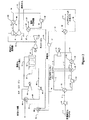
図1に示されるような第1の典型的な構造では、ランキンパワーサイクルは、多成分作動流体を使用し、発電がLNG再ガス化及び/又は処理プラントと動作的に結合されたクローズパワーサイクルである。最も典型的に、LNG再ガス化プラントは、表1に示されたガス組成をもつ1.2BSCFDの天然ガスを生産するように構成される。ここで、貯蔵庫(又は、その他の適切な供給源)からのLNGストリーム1は、約25psig〜80psigの圧力と約−260°F〜−250°Fの温度で供給される。ストリーム1は、LNGポンプ51によって、典型的に、加圧されたLNGストリーム2を形成するために約1200〜1500psigである適切な圧力まで、又は、特定のパイプライン要件を満たすために必要とされるようなその他の圧力まで送り込まれる。加圧されたLNGストリーム2は、交換器52内で作動流体ストリーム15により約−50°Fの温度まで加熱される。LNG再ガス化中の冷却放出は、多成分作動流体を凝縮するため使用される。

多成分作動流体に関して、一般的に好ましくは、作動流体組成は、再ガス化中にLNGの極低温温度、典型的に約−250°F〜約−50°Fを効率的に利用するため選択される。したがって、典型的な好ましい多成分作動流体は、10%のメタンと、40%のエタンと、50%のプロパンとからなる。しかし、代替的な適切な成分及びモル分率もまた適切であるとみなされ、主に所望の熱交換曲線と、LNGの温度及び組成と、所望の発電とに依存する。その結果として、適切な多成分流体は、約0°F〜100°F(露点温度)から約−150°F〜−180°F(沸点温度)までの可変温度で凝縮する。多成分流体の可変凝縮温度は、近接した温度アプローチ及び効率的なパワーサイクルを実現する際に非常に望ましい最小損失仕事をもつ可変LNG再ガス化温度を有利に利用することが理解されるべきである。なおさらに、混合された作業流体の組成及び成分は、典型的にLNG組成及び再ガス化圧力によって決定されるLNG気化曲線と適合するように必要に応じて調整され得ることが認められるべきである。よって、混合された作業流体は窒素のような炭化水素ではない成分をさらに含有する。熱交換器52の典型的な熱交換曲線は図6に示されている。
For multi-component working fluids, generally preferred, the working fluid composition is selected to efficiently utilize the cryogenic temperature of LNG during regasification, typically about −250 ° F. to about −50 ° F. Is done. Thus, a typical preferred multi-component working fluid consists of 10% methane, 40% ethane, and 50% propane. However, alternative suitable components and mole fractions are also considered appropriate and depend primarily on the desired heat exchange curve, the temperature and composition of the LNG, and the desired power generation. As a result, suitable multi-component fluids condense at variable temperatures from about 0 ° F. to 100 ° F. (dew point temperature) to about −150 ° F. to −180 ° F. (boiling point temperature). It should be understood that the variable condensing temperature of a multi-component fluid advantageously utilizes a variable LNG regasification temperature with a minimum loss work that is highly desirable in achieving a close temperature approach and efficient power cycling. is there. Still further, it should be appreciated that the composition and components of the mixed working fluid can be adjusted as needed to match the LNG vaporization curve typically determined by the LNG composition and regasification pressure. . Thus, the mixed working fluid further contains a non-hydrocarbon component such as nitrogen. A typical heat exchange curve for
図1をさらに参照すると、作業流体ストリーム10は、ポンプ53によって約1500psig(又は、それ以上、たとえば、1500−2500psig)までストリーム11へ送り込まれ、ストリーム12を形成するため、膨張器放出ストリーム14によって交換器68内で加熱される。加熱された流体はヒーター54内で、好ましくは、外部熱媒体91を用いて約500°Fまでさらに加熱される。あらゆるタイプの外部熱源がここで用いるため適切であると考えられ、典型的な熱源はガスタービン、廃熱回収ユニット、及び/又は、燃焼式ヒーターからの排気ガスを含むことが認められるであろう。よって、さらに加熱されたストリーム13の温度は著しく変化する。しかし、一般的に好ましくは、温度は少なくとも300°Fであり、より好ましくは、少なくとも350°F〜450°Fであり、最も好ましくは、約500°F以上(たとえば、550°F〜700°F以上)である。このようにして発生させられた高圧高温作業流体13は、次に、ストリーム14を形成する膨張器55内で約15psig〜45psigまで膨張させられ、発電機を駆動するため使用され得るパワーを発生する。膨張器放出ストリーム14中の残りの熱容量は、好ましくは、続いて、ランキンサイクルを繰り返すためにストリーム10を形成する交換器52において極低温温度で凝縮されるストリーム15を形成する交換器68内で回収される。
Still referring to FIG. 1, the working
このような典型的な構造では、約5000GPMの作動流体がランキンパワーサイクル内を循環させられ、約55000kWの電力を発生する。勿論、発電効率はより高い温度の作動流体を使用することによりさらに高められることに注意すべきである。代替的に、又は、付加的に、作動流体の圧力は、パワー生産を増やすため(たとえば、1500及び3000psig以上に)高められる。最終的に、経済上の考慮(たとえば、機器費用及び加熱所要量)は、作動流体の最も望ましい圧力及び温度を決定する。 In such a typical structure, approximately 5000 GPM of working fluid is circulated in the Rankine power cycle, generating approximately 55000 kW of power. Of course, it should be noted that the power generation efficiency is further enhanced by using a higher temperature working fluid. Alternatively or additionally, the working fluid pressure is increased to increase power production (eg, 1500 and 3000 psig and above). Ultimately, economic considerations (eg, equipment costs and heating requirements) determine the most desirable pressure and temperature of the working fluid.
図1による構造の第2の発電ステージにおいて、ストリーム3からの(約−50°F〜40°F)のLNGの残留冷却内容物は、複合サイクル発電プラント内で循環させられる熱伝達媒体(たとえば、グリコール−水混合物又はアルコールベースの溶媒)を冷やすために利用される。ここで、LNGは、グリコール−水混合物ストリーム21を用いて交換器56内で加熱される。LNGは、約40°Fまで気化されてストリーム4を形成し、一方、グリコール−水混合物は約0°F〜20°Fまで冷却される。最も好ましい態様では、冷やされたグリコール−水混合物22は、最初に、空気予冷却器57内で約100°Fから約40°〜50°Fまで燃焼用空気(ストリーム25)を冷やすため使用される。この冷却ステップにおいて、空気中の水分内容物の大部分は凝縮される(ストリーム26)。吸気からの水分内容物の除去は、有利的に、ガスタービン61による質量流量及び圧縮を削減し、これによって、ガスタービン発電機の電力消費を低減し、全体的な発電効率を高める。吸気からの凝縮水の量は大きく(たとえば、多湿性の場所で10体積百分率と同じ量)、発電効率は、その結果、実質的に高められることに注意すべきである。さらに、空気予冷却は、(冷やされた空気の密度の増加に起因して)ガスタービンを流れる空気質量流量をより高くすることをさらに可能にし、このことがガスタービンパワー出力及び効率を再び高める。典型的な図5A及び5Bは、周囲空気温度が従来型の複合サイクル発電プラントの発電に与える影響を示す。さらに、ガスタービン吸気冷却は、発電能力を周囲温度の変化から切り離すことに注意すべきである。従来型の発電プラントは、周囲温度が上昇するとき、パワー出力の降下に直面する。ガスタービン吸気冷却によって、パワー出力及び発電効率は、年間を通じて最適レベルに保たれ、発電プラントの経済的側面を劇的に改善する。図5A及び5Bに示されているように、空気予冷却は、典型的に、ガスタービン出力性能を約15%ずつ改善する。しかし、空気予冷却器に除氷装置が装備され、ガスタービンがより高い流量を取り扱うため設計されているならば、周囲空気がさらに冷却されるとき、より高い効率及び出力が達成されることが認められるであろう。
In the second power generation stage constructed according to FIG. 1, the residual cooling content of LNG from stream 3 (about −50 ° F. to 40 ° F.) is circulated in a heat transfer medium (eg, , Glycol-water mixtures or alcohol-based solvents). Here, LNG is heated in
図1をさらに参照すると、ガスタービン発電機61は、冷却され、好ましくは、乾燥した空気(ストリーム27)及び燃料ガス(ストリーム30)を発電のため使用する。燃料ガスは、気化されたLNG(ストリーム4)の一部分が典型的に250psig、又は、ガスタービンによって必要とされる他の圧力まで減圧された後、その気化されたLNGの一部分から供給される。燃料ガスの減圧は、付加的なパワーを生産するため(たとえば、ポンプ、コンプレッサ、又は、その他のコンポーネントを作動し、又は、発電するため)さらに使用されることが認められるであろう。ガスタービン排気(ストリーム33)からの熱は、典型的に、付加的なスチーム及びパワーの発生のための熱回収スチーム発生ユニット62(HRSG)によって捕捉される。冷却された燃料ガスストリーム34は、約300°F以下の温度でHRSGから雰囲気へ出る。
Still referring to FIG. 1, the
殆どの好ましい構造では、スチームサイクルは、典型的に、発電用の過熱されたスチーム41によって駆動される複数のマルチステージスチームタービン63を含む。グリコール−水冷却剤ストリーム23の使用によって、このようなサイクルにおける発電は実質的に促進されることに注意すべきである。ここで、典型的に水道システムからの約80°Fの冷却水ストリーム50は、交換器66内で冷却剤によって約50°Fまで冷やされ、それによって、ポンプ67により送り込まれてストリーム21を形成するストリーム24を形成する。冷やされた冷却水51は、次に、蒸気表面復水器64内で使用され、スチーム排気圧が低下され、発電が増大させられるので有利であるより低い温度で蒸気復水器が動作することを可能にする。たとえば、80°Fの冷却水を用いる従来型の蒸気表面復水器は、典型的に、約2psiaで動作し、一方、本発明の主旨による蒸気表面復水器は、約1psia以下の低い動作圧を有する。表面復水器の動作圧が低下することは、タービン排気圧が低下することを意味する。復水器43は、ポンプ65によって、ストリーム40を形成するために望ましい圧力まで送り込まれる。スチームタービンパワー出力は、典型的に、約10%〜13%増加される。
In most preferred configurations, the steam cycle typically includes a plurality of
必要に応じて、意図された構造は、図2に概略的に示されているように燃料ガス飽和器をさらに含む。ここで、第2のステージの空気予冷却器57から凝縮された水は、ストリーム26を介してポンプ58によって送り込まれてストリーム28を形成し、ストリーム28は加熱されたストリーム29を形成する約250°Fまで外部熱源92を使用するヒーター59でさらに加熱される。温水のストリーム29は、燃料ガスストリーム30と混合するため、典型的に向流接触装置であるカラム60へ送られる。技術的には多数の適切な接触装置が知られているが、特に好ましい装置は、熱と質量の伝達動作のため構成されたカラムパッキング又はカラムトレイを含む。このようにして飽和した燃料ガスは、次に、含水燃料ガスストリーム32としてガスタービン61の燃焼器へ供給され、余分の水はストリーム31を介して除去される。ガスタービンの膨張器セクションへの質量流量が増加すると、パワー出力が約10%増加することが認められるであろう。図2の残りの要素に関して、図1の同様の番号をもつ同様のコンポーネントに対する検討と同じ検討が適用される。
If desired, the intended structure further includes a fuel gas saturator as schematically illustrated in FIG. Here, the water condensed from the second
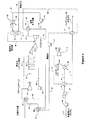
図3に示されているような(たとえば、外部作動流体が利用できないか、又は、望ましくない)第2の典型的な構造では、LNGはオープンランキンサイクルにおいて作動流体として使用される。このような構造では、LNGストリーム2は、第2のLNGポンプ53によって、好ましくは超臨界圧(たとえば、約1500psig〜2500psig、又は、それ以上)まで送り込まれ、約150°Fのストリーム3を形成するため膨張器放出ストリーム15と熱交換されるストリーム14を形成する。超臨界LNGは、ヒーター54内で外部熱源91を用いて約300°F〜500°F(又はそれ以上)までさらに加熱され、次に、発電機を駆動するため使用されるパワーを発生するため、膨張器55の中で約1000psig(又はその他の圧力、そして、最も好ましくはパイプライン圧力)まで膨張される。このようなオープンランキンパワーサイクルは、匹敵する動作条件下で約45000kWを発生するように計算される。図3の残りの要素に関して、図1の同様の番号をもつ同様のコンポーネントに対する検討と同じ検討が適用される。
In a second exemplary configuration as shown in FIG. 3 (eg, external working fluid is not available or desirable), LNG is used as the working fluid in an open Rankine cycle. In such a configuration, the
上記の図2のクローズ型混合コンポーネントサイクルと同じように、図3の意図されたオープンサイクル構造は、図4に概略的に示されるような燃料ガス飽和器をさらに含む。ここで、空気予冷却器57から凝縮された水は、燃料ガスを飽和させるため利用される。燃料飽和プロセスに関して、構造及び動作的特長は前の図2の構造において説明された構造及び動作的特長と実質的に同じであることに注意すべきである。図4の残りの要素に関して、図2及び図3の同様の番号をもつ同様のコンポーネントに対する検討と同じ検討が適用される。
Similar to the closed mixed component cycle of FIG. 2 above, the intended open cycle structure of FIG. 3 further includes a fuel gas saturator as schematically illustrated in FIG. Here, the water condensed from the
一般的に好ましくは、意図されたプラントの第1のステージにおいて、LNGストリームは所望の圧力まで送り込まれ、ランキンパワーサイクルを動作させるために低温を供給する。このようなプラントにおいて、LNGは、熱伝達媒体を冷やし、それによって、複合サイクルプラントのパワー出力と効率を高めるためにさらに使用される。その上、ガスタービン吸気口冷却器からの凝縮された水は、発電プラントへの燃料ガスを飽和させるため使用されてもよい。したがって、LNG再ガス化は燃料ガス燃焼式ヒーター又は海水ヒーターを用いることなく実現されることが認められる。 Generally preferably, in the first stage of the intended plant, the LNG stream is pumped to the desired pressure and provides a low temperature to operate the Rankine power cycle. In such plants, LNG is further used to cool the heat transfer medium, thereby increasing the power output and efficiency of the combined cycle plant. Moreover, the condensed water from the gas turbine inlet cooler may be used to saturate the fuel gas to the power plant. Therefore, it is recognized that LNG regasification can be realized without using a fuel gas combustion heater or a seawater heater.
その結果として、また、別の観点から見ると、LNG再ガス化プラントは、仕事を生産するために、少なくとも1種以上の炭化水素又はその他の成分(たとえば、10%のメタン、40%のエタン、及び、50%のプロパン)、又は、超臨界LNGを含有する多成分作動流体を膨張させる膨張器を含むランキンパワーサイクルを含む。ランキンサイクルは、好ましくは、パイプライン圧力以上の圧力までLNGを送り込み、任意で、膨張器排気を用いて加圧されたLNGを予熱し、外部熱源(たとえば、ガスタービン、廃熱回収ユニット、及び/又は、燃焼式ヒーターからの排気ガス)によってLNGを加熱する。ランキンサイクルを出るLNGは、約−50°Fの温度で、少なくとも部分的に気化される(たとえば、少なくとも30%、より典型的には少なくとも50%、そしてより典型的には少なくとも70〜90%気化される)。したがって、このように加熱されたLNGから低温がさらに取り出される。 As a result, and from another point of view, the LNG regasification plant can produce at least one hydrocarbon or other component (eg, 10% methane, 40% ethane) to produce work. , And 50% propane), or a Rankine power cycle that includes an expander that expands a multi-component working fluid containing supercritical LNG. The Rankine cycle preferably delivers LNG to a pressure above the pipeline pressure, and optionally preheats the pressurized LNG using the expander exhaust, and provides an external heat source (eg, gas turbine, waste heat recovery unit, and (Or exhaust gas from combustion heater). The LNG exiting the Rankine cycle is at least partially vaporized at a temperature of about −50 ° F. (eg, at least 30%, more typically at least 50%, and more typically at least 70-90%). Vaporized). Accordingly, the low temperature is further extracted from the LNG thus heated.
好ましいプラントにおいて、第2のステージが組み込まれ、(典型的に約−50°F〜40°Fで)予熱されたLNG中の残りの比較的高レベルの低温が熱伝達媒体(たとえば、グリコール−水混合物)を冷却するため使用され、この熱伝達媒体が次にガスタービンへの燃焼タービン吸気を冷却し、及び/又は、(たとえば、HRSGの)スチームサイクル内の表面復水器への冷却水を冷やす。このような構造は、実質的に複合サイクル発電プラントにおける発電効率を実質的に高める。 In a preferred plant, a second stage is incorporated and the remaining relatively high level of low temperature in the preheated LNG (typically at about -50 ° F to 40 ° F) causes the heat transfer medium (eg, glycol- This heat transfer medium then cools the combustion turbine intake to the gas turbine and / or cooling water to the surface condenser in the steam cycle (eg of HRSG) Cool down. Such a structure substantially increases the power generation efficiency in the combined cycle power plant.
さらに、意図されたプラントは、ガスタービンへの燃料ガスを飽和させるために第2のステージにおけるガスタービン空気予冷却器からの凝縮水を使用する第3のステージをさらに備える。飽和ステップは、典型的に、水の気化熱を供給するため、約200°F〜300°Fの外部熱源(たとえば、ガスタービン、廃熱回収ユニット、及び/又は、燃焼式ヒーターからの排気ガス)を使用する。通常は雰囲気へ放出される廃熱回収ユニットからの排気ガス(約300°F)からのような低レベルの廃熱が利用できることも認められるであろう。したがって、第3のステージは、ガスタービンの膨張器セクションへの質量流量を増加させ、それによって、ガスタービン発電効率及び出力をなおさらに増加させる。 Furthermore, the intended plant further comprises a third stage that uses the condensed water from the gas turbine air precooler in the second stage to saturate the fuel gas to the gas turbine. The saturation step typically provides about 200 ° F. to 300 ° F. external heat source (eg, exhaust gas from a gas turbine, waste heat recovery unit, and / or combustion heater) to provide the heat of vaporization of water. ). It will also be appreciated that low levels of waste heat are available, such as from exhaust gas (about 300 ° F.) from a waste heat recovery unit that is normally released to the atmosphere. Thus, the third stage increases the mass flow to the expander section of the gas turbine, thereby further increasing gas turbine power generation efficiency and power.
LNGはオープンランキンパワーサイクル中の作動流体として第1のステージで利用されるが、一般的に好ましくは、LNGは(ここでは、臨界凝縮圧力(cricondenbar)より高い)超臨界圧まで送り込まれ、膨張器排気及び(たとえば、プラントと一体化した、又は、プラントと熱的に結合された)付加的な熱源によって加熱され、パイプラインまで膨張させられる。このように膨張させられたLNGは、次に、第2のステージにおいて発電プラントへの冷却剤として利用され、その後にパイプラインガスになる。よって、一部の好ましい構造では、発電サイクルと、発電プラントの一体化は、LNGを再ガス化すると共に、低温内容物を利用する(ここで、LNGの組成と再ガス化されたLNGの組成は実質的に同じである)。膨張器吐き出し圧力は、好ましくは、およそパイプライン圧力であるので、膨張器の膨張比は制限され、したがって、前の多成分作動流体より効率が低い。しかし、このような構造は、外部作動流体を用いずに動作される点が有利であり、プロセス構造及び動作を実質的に簡単化することが認められであろう。 LNG is utilized in the first stage as a working fluid in an open Rankine power cycle, but generally preferably LNG is pumped to supercritical pressure (here higher than the critical condensation pressure) and expanded. It is heated by an exhaust source and an additional heat source (eg, integrated with the plant or thermally coupled to the plant) and expanded to the pipeline. The LNG thus expanded is then utilized as a coolant to the power plant in the second stage and then becomes pipeline gas. Thus, in some preferred structures, the integration of the power generation cycle and the power plant regasifies LNG and utilizes low temperature contents (where LNG composition and regasified LNG composition). Are substantially the same). Since the inflator discharge pressure is preferably about pipeline pressure, the expansion ratio of the inflator is limited and is therefore less efficient than the previous multi-component working fluid. However, it will be appreciated that such a structure is advantageous in that it is operated without an external working fluid, substantially simplifying the process structure and operation.
適切な熱源は、ガスタービン燃焼用空気、表面復水器への冷却水、及び/又は、ガスタービン又は燃料燃焼式ヒーターからの排気ガスを特に含む。しかし、多数の代替的な熱源もまた考えられ、複合サイクルプラント以外のユニットもまた熱源として適切であると考えられることがわかるであろう。たとえば、適切な代替的な熱源は、LNGが空気又はその他のガスを冷却する多数の極低温プロセス(たとえば、空気分離プラント)と、排気ガスを供給するプロセス(たとえば、燃焼タービン、改質排気ガスなど)と、冷シンクとして機能するその他のプロセス(たとえば、液体二酸化炭素生産プラント、淡水化プラント、又は、食品冷凍設備)とを含む。 Suitable heat sources specifically include gas turbine combustion air, cooling water to a surface condenser, and / or exhaust gas from a gas turbine or fuel combustion heater. However, it will be appreciated that numerous alternative heat sources are also contemplated, and units other than combined cycle plants may also be considered suitable as a heat source. For example, suitable alternative heat sources include a number of cryogenic processes (eg, air separation plants) in which LNG cools air or other gases, and processes that supply exhaust gases (eg, combustion turbines, reformed exhaust gases) And other processes that function as cold sinks (eg, liquid carbon dioxide production plants, desalination plants, or food refrigeration facilities).
一般的に好ましくは、適切なプラントは、LNG再ガス化設備及びLNG受入基地を含み、特に好ましい構造は、LNGの少なくとも一部が発電するため使用されるプロセスにおいてLNGが再ガス化され、好ましくは、複合パワーサイクルに一体化された、LNG再ガス化設備及びLNG受入基地を含む。本明細書で提案された教示と併せて使用するため適した典型的な構造は、参照してここに組み込まれた、出願番号がPCT/US03/25372及びPCT/US03/26805である同一出願人による同時係属中の国際特許出願に記載されている。よって、特定の熱源に依存して、LNGの再ガス化に必要なエネルギーは、意図された熱源によって完全に、又は、部分的に供給される。熱源がLNGをガス化するために不十分な量の熱を供給する場合、補助的な熱が供給されることがわかるであろう。適切な補助熱源は、スチームタービン放出からの廃熱、排気ガスからの凝縮負荷、(たとえば、建物に空調を設置することによる)空気、海水による周囲加熱、又は、燃料ガスを含む。その結果、意図された構造及びプロセスは、発電効率及び柔軟性を改良するために既存の再ガス化プラントを改造するため使用されてもよく、又は、新しい設備に使用されてもよいことがわかるであろう。 Generally preferably, a suitable plant includes an LNG regasification facility and an LNG receiving terminal, and a particularly preferred structure is that LNG is regasified in a process where at least a portion of the LNG is used to generate electricity, preferably Includes an LNG regasification facility and an LNG receiving base integrated into a combined power cycle. Exemplary structures suitable for use in conjunction with the teachings proposed herein are the same applicants with application numbers PCT / US03 / 25372 and PCT / US03 / 26805, incorporated herein by reference. In a co-pending international patent application. Thus, depending on the particular heat source, the energy required for LNG regasification is supplied completely or partially by the intended heat source. It will be appreciated that if the heat source supplies an insufficient amount of heat to gasify LNG, supplemental heat will be provided. Suitable auxiliary heat sources include waste heat from steam turbine emissions, condensation loads from exhaust gases, air (eg, by installing air conditioning in a building), ambient heating with seawater, or fuel gas. As a result, it is understood that the intended structure and process may be used to retrofit an existing regasification plant to improve power generation efficiency and flexibility, or may be used for new equipment. Will.
したがって、多数の利点が本発明の主旨による構造を使用して達成されることが認められるであろう。特に、意図された構造は、従来型の複合サイクル発電プラントと結合され得る外部作動流体の有無にかかわらず、非常に効率的なLNG発電サイクルを提供する。さらに、殆どの構造において、LNG再ガス化のための外部加熱は不要であり、よって、従来型のLNG再ガス化においてLNGを加熱するためにこれまで必要とされていた燃料ガス又は海水の必要性がなくなる。 Thus, it will be appreciated that a number of advantages are achieved using a structure according to the subject matter of the present invention. In particular, the intended structure provides a very efficient LNG power generation cycle with or without an external working fluid that can be combined with a conventional combined cycle power plant. In addition, in most configurations, no external heating for LNG regasification is required, thus the need for fuel gas or seawater previously required to heat LNG in conventional LNG regasification Sex is lost.
したがって、LNG再ガス化が一体化された発電の構造及び方法に関する具体的な実施形態及びアプリケーションが開示されている。しかし、上記された変更以外のより多数の変更が本明細書における発明の概念を逸脱することなく可能であることは当業者に明白であろう。したがって、本発明の主旨は、本開示の精神を除いては制限されるべきでない。その上、明細書を解釈する上で、すべての用語は、前後関係と一致したできるだけ広義に解釈されるべきである。特に、用語「備える、含む(comprises)」及び「備えている、含んでいる(comprising)」は、非排他的な意味で要素、コンポーネント、又は、ステップを参照していると解釈されるべきであり、参照された要素、コンポーネント、又は、ステップが、存在するか、利用されるか、明示的に参照されていない他の要素、コンポーネント、又は、ステップと組み合わされることを示している。 Accordingly, specific embodiments and applications for power generation structures and methods with integrated LNG regasification are disclosed. However, it will be apparent to those skilled in the art that many more modifications besides those described above are possible without departing from the inventive concepts herein. Accordingly, the spirit of the invention should not be limited except in the spirit of the present disclosure. Moreover, in interpreting the specification, all terms should be interpreted in the broadest possible manner consistent with the context. In particular, the terms “comprises” and “comprising” should be construed as referring to elements, components, or steps in a non-exclusive sense. Yes, indicates that a referenced element, component, or step is present, utilized, or combined with another element, component, or step that is not explicitly referenced.
Claims (7)
加熱されたLNGを受け入れ、気化されたLNGを発生するため熱伝達媒体流体を冷却するように構成された第2の熱交換器と、
熱伝達媒体を受け入れ、それぞれ吸気冷却器及びスチームタービンサイクルを冷却するように構成された第3の熱交換器及び第4の熱交換器と
を備える、複合サイクル発電プラント。A first heat exchanger configured to receive LNG and cool the working fluid to generate heated LNG, the working fluid being LNG to form an open power production cycle. A heat exchanger and an expander configured to receive a working fluid to drive a generator;
A second heat exchanger configured to receive the heated LNG and to cool the heat transfer medium fluid to generate vaporized LNG;
A combined cycle power plant comprising: a third heat exchanger and a fourth heat exchanger configured to receive a heat transfer medium and cool the intake air cooler and the steam turbine cycle, respectively.
電気を発電するために発電機に連結された膨張器を駆動するように作動流体をオープンパワーサイクルで使用するステップと、
熱交換媒体流体を冷却し、それによって、気化されたLNGを発生するため、第2の熱交換器内で加熱されたLNGをさらに加熱するステップと、
それぞれ吸気冷却器及びスチームタービンサイクルを冷却するため、第3の熱交換器及び第4の熱交換器内で熱伝達媒体を使用するステップと
を備える、複合サイクル発電プラントを運転する方法。Heating the LNG in the first heat exchanger to cool the working fluid, thereby generating heated LNG, the working fluid being LNG; and
Using a working fluid in an open power cycle to drive an expander coupled to a generator to generate electricity;
Further heating the LNG heated in the second heat exchanger to cool the heat exchange medium fluid and thereby generate vaporized LNG;
Using a heat transfer medium in a third heat exchanger and a fourth heat exchanger to cool the intake air cooler and the steam turbine cycle, respectively.
Applications Claiming Priority (3)
| Application Number | Priority Date | Filing Date | Title |
|---|---|---|---|
| US58827504P | 2004-07-14 | 2004-07-14 | |
| US60/588,275 | 2004-07-14 | ||
| PCT/US2005/024973 WO2006019900A1 (en) | 2004-07-14 | 2005-07-14 | Configurations and methods for power generation with integrated lng regasification |
Publications (2)
| Publication Number | Publication Date |
|---|---|
| JP2008506883A JP2008506883A (en) | 2008-03-06 |
| JP5202945B2 true JP5202945B2 (en) | 2013-06-05 |
Family
ID=35907713
Family Applications (1)
| Application Number | Title | Priority Date | Filing Date |
|---|---|---|---|
| JP2007521632A Expired - Fee Related JP5202945B2 (en) | 2004-07-14 | 2005-07-14 | Structure and method for power generation integrated with LNG regasification |
Country Status (10)
| Country | Link |
|---|---|
| US (1) | US7574856B2 (en) |
| EP (1) | EP1781902A4 (en) |
| JP (1) | JP5202945B2 (en) |
| AR (1) | AR049718A1 (en) |
| AU (1) | AU2005275156B2 (en) |
| CA (1) | CA2578243C (en) |
| EA (1) | EA009276B1 (en) |
| MX (1) | MX2007000341A (en) |
| NO (1) | NO20070748L (en) |
| WO (1) | WO2006019900A1 (en) |
Families Citing this family (133)
| Publication number | Priority date | Publication date | Assignee | Title |
|---|---|---|---|---|
| US20070062216A1 (en) * | 2003-08-13 | 2007-03-22 | John Mak | Liquefied natural gas regasification configuration and method |
| CA2461086C (en) * | 2004-03-09 | 2010-12-21 | Jose Lourenco | Method of power generation from pressure control stations of a natural gas distribution system |
| EP1734027B1 (en) * | 2005-06-14 | 2012-08-15 | Toyo Engineering Corporation | Process and Apparatus for Separation of Hydrocarbons from Liquefied Natural Gas |
| CA2551062C (en) * | 2006-06-08 | 2012-02-14 | Jose Lourenco | Method for re-gasification of liquid natural gas |
| CA2552327C (en) | 2006-07-13 | 2014-04-15 | Mackenzie Millar | Method for selective extraction of natural gas liquids from "rich" natural gas |
| US8887513B2 (en) * | 2006-11-03 | 2014-11-18 | Kellogg Brown & Root Llc | Three-shell cryogenic fluid heater |
| EP2133515A4 (en) * | 2007-04-11 | 2014-07-30 | Hitachi Ltd | Power supply equipment for natural gas liquefaction plant |
| US20150192298A1 (en) * | 2007-07-27 | 2015-07-09 | United Technologies Corporation | Gas turbine engine with improved fuel efficiency |
| US20150132106A1 (en) * | 2007-07-27 | 2015-05-14 | United Technologies Corporation | Gas turbine engine with low fan pressure ratio |
| US8973398B2 (en) * | 2008-02-27 | 2015-03-10 | Kellogg Brown & Root Llc | Apparatus and method for regasification of liquefied natural gas |
| AU2009228283B2 (en) | 2008-03-28 | 2015-02-05 | Exxonmobil Upstream Research Company | Low emission power generation and hydrocarbon recovery systems and methods |
| CA2730505C (en) * | 2008-07-17 | 2014-12-02 | Fluor Technologies Corporation | Configurations and methods for waste heat recovery and ambient air vaporizers in lng regasification |
| US8383870B2 (en) | 2008-07-18 | 2013-02-26 | Federal Express Corporation | Environmentally friendly methods and systems of energy production |
| JP5580320B2 (en) | 2008-10-14 | 2014-08-27 | エクソンモービル アップストリーム リサーチ カンパニー | Method and system for controlling combustion products |
| US8132411B2 (en) * | 2008-11-06 | 2012-03-13 | Air Products And Chemicals, Inc. | Rankine cycle for LNG vaporization/power generation process |
| US9885313B2 (en) | 2009-03-17 | 2018-02-06 | United Technologes Corporation | Gas turbine engine bifurcation located fan variable area nozzle |
| CN102414522B (en) * | 2009-04-29 | 2014-03-05 | 开利公司 | Transcritical thermally activated cooling, heating and refrigerating system |
| US8479489B2 (en) * | 2009-08-27 | 2013-07-09 | General Electric Company | Turbine exhaust recirculation |
| EP2499332B1 (en) | 2009-11-12 | 2017-05-24 | Exxonmobil Upstream Research Company | Integrated system for power generation and method for low emission hydrocarbon recovery with power generation |
| US8545681B2 (en) * | 2009-12-23 | 2013-10-01 | General Electric Company | Waste heat driven desalination process |
| CN101806293B (en) * | 2010-03-10 | 2012-03-28 | 华南理工大学 | Integrating and optimizing method for improving generation efficiency of liquefied natural gas cold energy |
| US20110289941A1 (en) * | 2010-05-28 | 2011-12-01 | General Electric Company | Brayton cycle regasification of liquiefied natural gas |
| EA026404B1 (en) | 2010-07-02 | 2017-04-28 | Эксонмобил Апстрим Рисерч Компани | Integrated system and method of generating power |
| SG10201505209UA (en) | 2010-07-02 | 2015-08-28 | Exxonmobil Upstream Res Co | Low emission power generation systems and methods |
| MY164051A (en) | 2010-07-02 | 2017-11-15 | Exxonmobil Upstream Res Co | Low emission triple-cycle power generation systems and methods |
| SG186157A1 (en) | 2010-07-02 | 2013-01-30 | Exxonmobil Upstream Res Co | Stoichiometric combustion of enriched air with exhaust gas recirculation |
| WO2012054512A1 (en) * | 2010-10-19 | 2012-04-26 | Hydro Resources | Apparatus and method for producing electric power from injection of water into a downhole formation |
| US10451344B2 (en) | 2010-12-23 | 2019-10-22 | Fluor Technologies Corporation | Ethane recovery and ethane rejection methods and configurations |
| US20120167619A1 (en) * | 2010-12-30 | 2012-07-05 | Chevron U.S.A. Inc. | Method to maximize lng plant capacity in all seasons |
| WO2012102849A1 (en) | 2011-01-28 | 2012-08-02 | Exxonmobil Upstream Research Company | Regasification plant |
| WO2012104202A1 (en) * | 2011-02-01 | 2012-08-09 | Alstom Technology Ltd | Combined cycle power plant with co2 capture plant |
| TWI593872B (en) | 2011-03-22 | 2017-08-01 | 艾克頌美孚上游研究公司 | Integrated system and methods of generating power |
| TWI563165B (en) | 2011-03-22 | 2016-12-21 | Exxonmobil Upstream Res Co | Power generation system and method for generating power |
| TWI563166B (en) | 2011-03-22 | 2016-12-21 | Exxonmobil Upstream Res Co | Integrated generation systems and methods for generating power |
| TWI564474B (en) | 2011-03-22 | 2017-01-01 | 艾克頌美孚上游研究公司 | Integrated systems for controlling stoichiometric combustion in turbine systems and methods of generating power using the same |
| CN104428490B (en) | 2011-12-20 | 2018-06-05 | 埃克森美孚上游研究公司 | The coal bed methane production of raising |
| CA2763081C (en) | 2011-12-20 | 2019-08-13 | Jose Lourenco | Method to produce liquefied natural gas (lng) at midstream natural gas liquids (ngls) recovery plants. |
| US9291064B2 (en) * | 2012-01-31 | 2016-03-22 | United Technologies Corporation | Anti-icing core inlet stator assembly for a gas turbine engine |
| CA2772479C (en) | 2012-03-21 | 2020-01-07 | Mackenzie Millar | Temperature controlled method to liquefy gas and a production plant using the method. |
| US9353682B2 (en) | 2012-04-12 | 2016-05-31 | General Electric Company | Methods, systems and apparatus relating to combustion turbine power plants with exhaust gas recirculation |
| US9784185B2 (en) | 2012-04-26 | 2017-10-10 | General Electric Company | System and method for cooling a gas turbine with an exhaust gas provided by the gas turbine |
| US10273880B2 (en) | 2012-04-26 | 2019-04-30 | General Electric Company | System and method of recirculating exhaust gas for use in a plurality of flow paths in a gas turbine engine |
| CA2790961C (en) | 2012-05-11 | 2019-09-03 | Jose Lourenco | A method to recover lpg and condensates from refineries fuel gas streams. |
| US9476323B2 (en) * | 2012-05-31 | 2016-10-25 | United Technologies Corporation | Turbine gear assembly support having symmetrical removal features |
| US20130318998A1 (en) * | 2012-05-31 | 2013-12-05 | Frederick M. Schwarz | Geared turbofan with three turbines with high speed fan drive turbine |
| DE102012020304A1 (en) * | 2012-08-23 | 2014-02-27 | Linde Aktiengesellschaft | Process for vaporizing LNG |
| CA2787746C (en) | 2012-08-27 | 2019-08-13 | Mackenzie Millar | Method of producing and distributing liquid natural gas |
| US8753065B2 (en) | 2012-09-27 | 2014-06-17 | United Technologies Corporation | Method for setting a gear ratio of a fan drive gear system of a gas turbine engine |
| US8807916B2 (en) * | 2012-09-27 | 2014-08-19 | United Technologies Corporation | Method for setting a gear ratio of a fan drive gear system of a gas turbine engine |
| US9599070B2 (en) | 2012-11-02 | 2017-03-21 | General Electric Company | System and method for oxidant compression in a stoichiometric exhaust gas recirculation gas turbine system |
| US9631815B2 (en) | 2012-12-28 | 2017-04-25 | General Electric Company | System and method for a turbine combustor |
| US9708977B2 (en) | 2012-12-28 | 2017-07-18 | General Electric Company | System and method for reheat in gas turbine with exhaust gas recirculation |
| US9611756B2 (en) | 2012-11-02 | 2017-04-04 | General Electric Company | System and method for protecting components in a gas turbine engine with exhaust gas recirculation |
| US9869279B2 (en) | 2012-11-02 | 2018-01-16 | General Electric Company | System and method for a multi-wall turbine combustor |
| US10215412B2 (en) | 2012-11-02 | 2019-02-26 | General Electric Company | System and method for load control with diffusion combustion in a stoichiometric exhaust gas recirculation gas turbine system |
| US10107495B2 (en) | 2012-11-02 | 2018-10-23 | General Electric Company | Gas turbine combustor control system for stoichiometric combustion in the presence of a diluent |
| US10100741B2 (en) | 2012-11-02 | 2018-10-16 | General Electric Company | System and method for diffusion combustion with oxidant-diluent mixing in a stoichiometric exhaust gas recirculation gas turbine system |
| US9574496B2 (en) | 2012-12-28 | 2017-02-21 | General Electric Company | System and method for a turbine combustor |
| US9803865B2 (en) | 2012-12-28 | 2017-10-31 | General Electric Company | System and method for a turbine combustor |
| CA2798057C (en) | 2012-12-04 | 2019-11-26 | Mackenzie Millar | A method to produce lng at gas pressure letdown stations in natural gas transmission pipeline systems |
| US10208677B2 (en) | 2012-12-31 | 2019-02-19 | General Electric Company | Gas turbine load control system |
| US9581081B2 (en) | 2013-01-13 | 2017-02-28 | General Electric Company | System and method for protecting components in a gas turbine engine with exhaust gas recirculation |
| US9512759B2 (en) | 2013-02-06 | 2016-12-06 | General Electric Company | System and method for catalyst heat utilization for gas turbine with exhaust gas recirculation |
| US9938861B2 (en) | 2013-02-21 | 2018-04-10 | Exxonmobil Upstream Research Company | Fuel combusting method |
| TW201502356A (en) | 2013-02-21 | 2015-01-16 | Exxonmobil Upstream Res Co | Reducing oxygen in a gas turbine exhaust |
| RU2637609C2 (en) | 2013-02-28 | 2017-12-05 | Эксонмобил Апстрим Рисерч Компани | System and method for turbine combustion chamber |
| US9618261B2 (en) | 2013-03-08 | 2017-04-11 | Exxonmobil Upstream Research Company | Power generation and LNG production |
| TW201500635A (en) | 2013-03-08 | 2015-01-01 | Exxonmobil Upstream Res Co | Processing exhaust for use in enhanced oil recovery |
| US20140250945A1 (en) | 2013-03-08 | 2014-09-11 | Richard A. Huntington | Carbon Dioxide Recovery |
| AU2014226413B2 (en) | 2013-03-08 | 2016-04-28 | Exxonmobil Upstream Research Company | Power generation and methane recovery from methane hydrates |
| US9790775B2 (en) | 2013-03-15 | 2017-10-17 | Schlumberger Technology Corporation | Stimulation with natural gas |
| CA2813260C (en) | 2013-04-15 | 2021-07-06 | Mackenzie Millar | A method to produce lng |
| US9347376B2 (en) * | 2013-04-24 | 2016-05-24 | General Electric Company | Liquified fuel backup fuel supply for a gas turbine |
| US20150308348A1 (en) * | 2013-05-22 | 2015-10-29 | United Technologies Corporation | Continuous detonation wave turbine engine |
| US9631542B2 (en) | 2013-06-28 | 2017-04-25 | General Electric Company | System and method for exhausting combustion gases from gas turbine engines |
| US9617914B2 (en) | 2013-06-28 | 2017-04-11 | General Electric Company | Systems and methods for monitoring gas turbine systems having exhaust gas recirculation |
| US9835089B2 (en) | 2013-06-28 | 2017-12-05 | General Electric Company | System and method for a fuel nozzle |
| TWI654368B (en) | 2013-06-28 | 2019-03-21 | 美商艾克頌美孚上游研究公司 | System, method and media for controlling exhaust gas flow in an exhaust gas recirculation gas turbine system |
| US9903588B2 (en) | 2013-07-30 | 2018-02-27 | General Electric Company | System and method for barrier in passage of combustor of gas turbine engine with exhaust gas recirculation |
| US9587510B2 (en) | 2013-07-30 | 2017-03-07 | General Electric Company | System and method for a gas turbine engine sensor |
| US9951658B2 (en) | 2013-07-31 | 2018-04-24 | General Electric Company | System and method for an oxidant heating system |
| CN103486438B (en) * | 2013-09-18 | 2015-06-03 | 华南理工大学 | LNG gasification system based on double-heat-source heat pump |
| US9752458B2 (en) | 2013-12-04 | 2017-09-05 | General Electric Company | System and method for a gas turbine engine |
| US10030588B2 (en) | 2013-12-04 | 2018-07-24 | General Electric Company | Gas turbine combustor diagnostic system and method |
| US10227920B2 (en) | 2014-01-15 | 2019-03-12 | General Electric Company | Gas turbine oxidant separation system |
| US9863267B2 (en) | 2014-01-21 | 2018-01-09 | General Electric Company | System and method of control for a gas turbine engine |
| US9915200B2 (en) | 2014-01-21 | 2018-03-13 | General Electric Company | System and method for controlling the combustion process in a gas turbine operating with exhaust gas recirculation |
| US10079564B2 (en) | 2014-01-27 | 2018-09-18 | General Electric Company | System and method for a stoichiometric exhaust gas recirculation gas turbine system |
| FR3020094A1 (en) * | 2014-04-22 | 2015-10-23 | Ge Energy Products France Snc | METHOD FOR OPERATING A GAS TURBINE INVOLVING THE COMBUSTION OF VANADIUM CONTAMINATED LIQUID FUEL |
| US10047633B2 (en) | 2014-05-16 | 2018-08-14 | General Electric Company | Bearing housing |
| US20150361921A1 (en) * | 2014-06-13 | 2015-12-17 | United Technologies Corporation | Modifying Direct Drive Gas Turbine Engine Core to Provide a Geared Turbofan |
| US9885290B2 (en) | 2014-06-30 | 2018-02-06 | General Electric Company | Erosion suppression system and method in an exhaust gas recirculation gas turbine system |
| US10060359B2 (en) | 2014-06-30 | 2018-08-28 | General Electric Company | Method and system for combustion control for gas turbine system with exhaust gas recirculation |
| US10655542B2 (en) | 2014-06-30 | 2020-05-19 | General Electric Company | Method and system for startup of gas turbine system drive trains with exhaust gas recirculation |
| WO2016023098A1 (en) | 2014-08-15 | 2016-02-18 | 1304338 Alberta Ltd. | A method of removing carbon dioxide during liquid natural gas production from natural gas at gas pressure letdown stations |
| US9819292B2 (en) | 2014-12-31 | 2017-11-14 | General Electric Company | Systems and methods to respond to grid overfrequency events for a stoichiometric exhaust recirculation gas turbine |
| US9869247B2 (en) | 2014-12-31 | 2018-01-16 | General Electric Company | Systems and methods of estimating a combustion equivalence ratio in a gas turbine with exhaust gas recirculation |
| US10788212B2 (en) | 2015-01-12 | 2020-09-29 | General Electric Company | System and method for an oxidant passageway in a gas turbine system with exhaust gas recirculation |
| US10094566B2 (en) | 2015-02-04 | 2018-10-09 | General Electric Company | Systems and methods for high volumetric oxidant flow in gas turbine engine with exhaust gas recirculation |
| US10316746B2 (en) | 2015-02-04 | 2019-06-11 | General Electric Company | Turbine system with exhaust gas recirculation, separation and extraction |
| US10253690B2 (en) | 2015-02-04 | 2019-04-09 | General Electric Company | Turbine system with exhaust gas recirculation, separation and extraction |
| US10267270B2 (en) | 2015-02-06 | 2019-04-23 | General Electric Company | Systems and methods for carbon black production with a gas turbine engine having exhaust gas recirculation |
| US10077938B2 (en) | 2015-02-09 | 2018-09-18 | Fluor Technologies Corporation | Methods and configuration of an NGL recovery process for low pressure rich feed gas |
| US10145269B2 (en) | 2015-03-04 | 2018-12-04 | General Electric Company | System and method for cooling discharge flow |
| US10480792B2 (en) | 2015-03-06 | 2019-11-19 | General Electric Company | Fuel staging in a gas turbine engine |
| ES2599357B2 (en) * | 2015-07-31 | 2017-06-28 | Universidade Da Coruña | Rankine three-cycle thermoelectric plant and a direct expansion turbine whose cold focus comes from the regasification of liquefied natural gas |
| US11173445B2 (en) | 2015-09-16 | 2021-11-16 | 1304338 Alberta Ltd. | Method of preparing natural gas at a gas pressure reduction stations to produce liquid natural gas (LNG) |
| EP3184876A1 (en) | 2015-12-23 | 2017-06-28 | Shell Internationale Research Maatschappij B.V. | Liquid natural gas cogeneration regasification terminal |
| US20170191750A1 (en) * | 2015-12-31 | 2017-07-06 | General Electric Company | System and method for compressor intercooler |
| US10006701B2 (en) | 2016-01-05 | 2018-06-26 | Fluor Technologies Corporation | Ethane recovery or ethane rejection operation |
| US10330382B2 (en) | 2016-05-18 | 2019-06-25 | Fluor Technologies Corporation | Systems and methods for LNG production with propane and ethane recovery |
| WO2018006170A1 (en) * | 2016-07-08 | 2018-01-11 | Cegen Green Energy Ltd. | Pipeline-transport compressor including cooler unit and air exhaust power generation unit |
| BR112019003090A2 (en) | 2016-09-09 | 2019-05-21 | Fluor Technologies Corporation | methods and configuration for refurbishing ngl plant for high ethane recovery |
| IT201600121521A1 (en) * | 2016-11-30 | 2018-05-30 | Saipem Spa | ORGANIC RANKINE CYCLE IN CRYOGENIC OR REFRIGERANT FLUID APPLICATIONS |
| US10830105B2 (en) | 2016-12-12 | 2020-11-10 | General Electric Company | System and method for improving output and heat rate for a liquid natural gas combined cycle power plant |
| IT201700096779A1 (en) * | 2017-08-29 | 2019-03-01 | Nuovo Pignone Tecnologie Srl | SYSTEM AND COMBINED METHOD OF HEAT RECOVERY AND REFRIGERATION |
| JP2019044678A (en) | 2017-08-31 | 2019-03-22 | 三菱重工業株式会社 | Steam turbine system and combined cycle plant |
| WO2019078892A1 (en) | 2017-10-20 | 2019-04-25 | Fluor Technologies Corporation | Phase implementation of natural gas liquid recovery plants |
| EP3489473A1 (en) | 2017-11-27 | 2019-05-29 | Siemens Aktiengesellschaft | Improved method for power generation in the re-gasification of a fluid by means of supercritical relaxation |
| EP3517742A1 (en) * | 2018-01-26 | 2019-07-31 | Siemens Aktiengesellschaft | Generation of electric power and vaporisation of a cryogenically liquefied gas |
| JP7160493B2 (en) * | 2018-06-27 | 2022-10-25 | ミツビシ パワー アメリカズ インコーポレイテッド | Organic Rankine Cycle for Combined Cycle Power Plants |
| EP3591195A1 (en) * | 2018-07-05 | 2020-01-08 | Siemens Aktiengesellschaft | Expanded gas turbine process with natural gas re-gasification |
| EP3594460A1 (en) * | 2018-07-13 | 2020-01-15 | Siemens Aktiengesellschaft | Power plant with natural gas re-gasification |
| US11604169B2 (en) * | 2019-01-10 | 2023-03-14 | Shuyong Paul Du | Renewable power system and method for pipeline inspection tools |
| KR102403854B1 (en) * | 2019-03-20 | 2022-05-31 | 삼성중공업 주식회사 | Power generating system using LNG gas |
| CN113950568A (en) * | 2019-05-10 | 2022-01-18 | 三菱动力美洲株式会社 | Dual cycle system for a combined cycle power plant |
| CN110925042A (en) * | 2019-12-24 | 2020-03-27 | 青岛中稷龙源能源科技有限公司 | Multistage LNG cold energy power generation and comprehensive utilization system and method |
| EP4150196B1 (en) * | 2020-05-13 | 2023-11-01 | Just in Time Energy Co. | Re-condensing power cycle for fluid regasification |
| KR102352669B1 (en) * | 2020-09-25 | 2022-01-18 | 고등기술연구원연구조합 | Liquefied Gas Regasification and Power Generation System and Method |
| JP7059347B2 (en) * | 2020-12-24 | 2022-04-25 | 三菱重工業株式会社 | Waste heat recovery plant and combined cycle plant |
| KR102581239B1 (en) * | 2021-10-13 | 2023-09-20 | 에스케이가스 주식회사 | Lng refrigerated generation by using mixed working fluid |
| CN114111173B (en) * | 2021-12-03 | 2023-06-02 | 航天科工哈尔滨风华有限公司 | Gasifier system applicable to different latitudes and inland and application method thereof |
| WO2023244179A1 (en) * | 2022-06-17 | 2023-12-21 | Twenty20 Energy Systems Pte Ltd | Power generation system |
Family Cites Families (13)
| Publication number | Priority date | Publication date | Assignee | Title |
|---|---|---|---|---|
| CH584837A5 (en) * | 1974-11-22 | 1977-02-15 | Sulzer Ag | |
| DE2523672C3 (en) * | 1975-05-28 | 1980-03-20 | Gutehoffnungshuette Sterkrade Ag, 4200 Oberhausen | Device for the evaporation of liquefied natural gas with the aid of a gas turbine system with a closed circuit |
| JPS5554614A (en) | 1978-09-18 | 1980-04-22 | Fluor Corp | Method of picking out mechanical or electrical energy |
| DK71779A (en) * | 1979-02-19 | 1980-08-20 | Surgimed As | PROCEDURE AND APPARATUS FOR MANUFACTURING PIPE PRODUCTS ISA Catheters |
| JPS5925851B2 (en) * | 1979-06-22 | 1984-06-21 | 千代田化工建設株式会社 | Power recovery method using liquefied natural gas vaporization and cold heat using the cascade Rankine cycle |
| US5295350A (en) * | 1992-06-26 | 1994-03-22 | Texaco Inc. | Combined power cycle with liquefied natural gas (LNG) and synthesis or fuel gas |
| JP2856552B2 (en) * | 1993-12-10 | 1999-02-10 | キャボット コーポレイション | Improved co-cycle plant using liquefied natural gas as fuel. |
| CN1112505C (en) | 1995-06-01 | 2003-06-25 | 特雷克特贝尔Lng北美公司 | Liquefied natural gas (LNG) fueled combined cycle power plant and LNG fueled gas turbine plant |
| DE19757588A1 (en) * | 1996-12-24 | 1998-07-02 | Hitachi Ltd | Electricity generating system with gas turbine and energy storage |
| TW414851B (en) | 1998-03-27 | 2000-12-11 | Exxon Production Research Co | Producing power from liquefied natural gas |
| US20030005698A1 (en) * | 2001-05-30 | 2003-01-09 | Conoco Inc. | LNG regassification process and system |
| EP1634023B1 (en) | 2003-06-05 | 2011-11-30 | Fluor Corporation | Liquefied natural gas regasification configuration and method |
| WO2005043032A1 (en) | 2003-10-29 | 2005-05-12 | Shell Internationale Research Maatschappij B.V. | Unloading equipment systems for liquefied natural gas storage structure |
-
2005
- 2005-07-14 US US11/571,901 patent/US7574856B2/en not_active Expired - Fee Related
- 2005-07-14 EA EA200700241A patent/EA009276B1/en not_active IP Right Cessation
- 2005-07-14 JP JP2007521632A patent/JP5202945B2/en not_active Expired - Fee Related
- 2005-07-14 WO PCT/US2005/024973 patent/WO2006019900A1/en active Application Filing
- 2005-07-14 CA CA002578243A patent/CA2578243C/en not_active Expired - Fee Related
- 2005-07-14 AU AU2005275156A patent/AU2005275156B2/en not_active Ceased
- 2005-07-14 EP EP05770858A patent/EP1781902A4/en not_active Withdrawn
- 2005-07-14 MX MX2007000341A patent/MX2007000341A/en active IP Right Grant
- 2005-07-15 AR ARP050102934A patent/AR049718A1/en active IP Right Grant
-
2007
- 2007-02-08 NO NO20070748A patent/NO20070748L/en not_active Application Discontinuation
Also Published As
| Publication number | Publication date |
|---|---|
| CA2578243C (en) | 2010-02-02 |
| AU2005275156B2 (en) | 2011-03-24 |
| EP1781902A4 (en) | 2009-08-12 |
| AU2005275156A1 (en) | 2006-02-23 |
| NO20070748L (en) | 2007-02-13 |
| US7574856B2 (en) | 2009-08-18 |
| AR049718A1 (en) | 2006-08-30 |
| CA2578243A1 (en) | 2006-02-23 |
| WO2006019900A1 (en) | 2006-02-23 |
| JP2008506883A (en) | 2008-03-06 |
| EP1781902A1 (en) | 2007-05-09 |
| US20080190106A1 (en) | 2008-08-14 |
| MX2007000341A (en) | 2007-03-27 |
| EA200700241A1 (en) | 2007-08-31 |
| EA009276B1 (en) | 2007-12-28 |
Similar Documents
| Publication | Publication Date | Title |
|---|---|---|
| JP5202945B2 (en) | Structure and method for power generation integrated with LNG regasification | |
| JP5026588B2 (en) | LNG regasification and power generation | |
| US7299619B2 (en) | Vaporization of liquefied natural gas for increased efficiency in power cycles | |
| US7637109B2 (en) | Power generation system including a gas generator combined with a liquified natural gas supply | |
| JP4494338B2 (en) | Power cycle by regasification of liquefied natural gas | |
| CN105423125B (en) | It is used for Waste Heat Recovery and the arrangements and methods of ambient air vaporizer in lng regas | |
| US20060174627A1 (en) | Gas turbine cycle | |
| CA2615850C (en) | Configurations and methods for power generation in lng regasification terminals | |
| US20150192065A1 (en) | Process and apparatus for generating electric energy | |
| JP2001193483A (en) | Gas turbine system | |
| JP2001141359A (en) | Air separator | |
| Kaczmarek et al. | Effectiveness of operation of organic rankine cycle installation applied in the liquid natural gas regasification plant | |
| MXPA05013046A (en) | Power cycle with liquefied natural gas regasification | |
| JP2005068212A (en) | Gas hydrate manufacturing system |
Legal Events
| Date | Code | Title | Description |
|---|---|---|---|
| A131 | Notification of reasons for refusal |
Free format text: JAPANESE INTERMEDIATE CODE: A131 Effective date: 20091208 |
|
| A601 | Written request for extension of time |
Free format text: JAPANESE INTERMEDIATE CODE: A601 Effective date: 20100305 |
|
| A602 | Written permission of extension of time |
Free format text: JAPANESE INTERMEDIATE CODE: A602 Effective date: 20100312 |
|
| A521 | Written amendment |
Free format text: JAPANESE INTERMEDIATE CODE: A523 Effective date: 20100608 |
|
| A02 | Decision of refusal |
Free format text: JAPANESE INTERMEDIATE CODE: A02 Effective date: 20101026 |
|
| A521 | Written amendment |
Free format text: JAPANESE INTERMEDIATE CODE: A523 Effective date: 20110225 |
|
| A521 | Written amendment |
Free format text: JAPANESE INTERMEDIATE CODE: A523 Effective date: 20110228 |
|
| A911 | Transfer to examiner for re-examination before appeal (zenchi) |
Free format text: JAPANESE INTERMEDIATE CODE: A911 Effective date: 20110412 |
|
| A912 | Re-examination (zenchi) completed and case transferred to appeal board |
Free format text: JAPANESE INTERMEDIATE CODE: A912 Effective date: 20110527 |
|
| A601 | Written request for extension of time |
Free format text: JAPANESE INTERMEDIATE CODE: A601 Effective date: 20111121 |
|
| A602 | Written permission of extension of time |
Free format text: JAPANESE INTERMEDIATE CODE: A602 Effective date: 20111129 |
|
| A601 | Written request for extension of time |
Free format text: JAPANESE INTERMEDIATE CODE: A601 Effective date: 20120712 |
|
| A602 | Written permission of extension of time |
Free format text: JAPANESE INTERMEDIATE CODE: A602 Effective date: 20120718 |
|
| A521 | Written amendment |
Free format text: JAPANESE INTERMEDIATE CODE: A523 Effective date: 20121017 |
|
| A61 | First payment of annual fees (during grant procedure) |
Free format text: JAPANESE INTERMEDIATE CODE: A61 Effective date: 20130213 |
|
| R150 | Certificate of patent or registration of utility model |
Ref document number: 5202945 Country of ref document: JP Free format text: JAPANESE INTERMEDIATE CODE: R150 Free format text: JAPANESE INTERMEDIATE CODE: R150 |
|
| FPAY | Renewal fee payment (event date is renewal date of database) |
Free format text: PAYMENT UNTIL: 20160222 Year of fee payment: 3 |
|
| R250 | Receipt of annual fees |
Free format text: JAPANESE INTERMEDIATE CODE: R250 |
|
| R250 | Receipt of annual fees |
Free format text: JAPANESE INTERMEDIATE CODE: R250 |
|
| R250 | Receipt of annual fees |
Free format text: JAPANESE INTERMEDIATE CODE: R250 |
|
| LAPS | Cancellation because of no payment of annual fees |