JP5199295B2 - Operating device, electronic device including the operating device, and image processing apparatus - Google Patents
Operating device, electronic device including the operating device, and image processing apparatus Download PDFInfo
- Publication number
- JP5199295B2 JP5199295B2 JP2010033289A JP2010033289A JP5199295B2 JP 5199295 B2 JP5199295 B2 JP 5199295B2 JP 2010033289 A JP2010033289 A JP 2010033289A JP 2010033289 A JP2010033289 A JP 2010033289A JP 5199295 B2 JP5199295 B2 JP 5199295B2
- Authority
- JP
- Japan
- Prior art keywords
- display
- mode
- user
- touch panel
- image forming
- Prior art date
- Legal status (The legal status is an assumption and is not a legal conclusion. Google has not performed a legal analysis and makes no representation as to the accuracy of the status listed.)
- Active
Links
Images


Classifications
-
- H—ELECTRICITY
- H04—ELECTRIC COMMUNICATION TECHNIQUE
- H04N—PICTORIAL COMMUNICATION, e.g. TELEVISION
- H04N1/00—Scanning, transmission or reproduction of documents or the like, e.g. facsimile transmission; Details thereof
- H04N1/0035—User-machine interface; Control console
- H04N1/00352—Input means
- H04N1/00384—Key input means, e.g. buttons or keypads
-
- H—ELECTRICITY
- H04—ELECTRIC COMMUNICATION TECHNIQUE
- H04N—PICTORIAL COMMUNICATION, e.g. TELEVISION
- H04N1/00—Scanning, transmission or reproduction of documents or the like, e.g. facsimile transmission; Details thereof
- H04N1/0035—User-machine interface; Control console
- H04N1/00405—Output means
- H04N1/00408—Display of information to the user, e.g. menus
- H04N1/00411—Display of information to the user, e.g. menus the display also being used for user input, e.g. touch screen
-
- G—PHYSICS
- G03—PHOTOGRAPHY; CINEMATOGRAPHY; ANALOGOUS TECHNIQUES USING WAVES OTHER THAN OPTICAL WAVES; ELECTROGRAPHY; HOLOGRAPHY
- G03G—ELECTROGRAPHY; ELECTROPHOTOGRAPHY; MAGNETOGRAPHY
- G03G15/00—Apparatus for electrographic processes using a charge pattern
- G03G15/50—Machine control of apparatus for electrographic processes using a charge pattern, e.g. regulating differents parts of the machine, multimode copiers, microprocessor control
- G03G15/5016—User-machine interface; Display panels; Control console
- G03G15/502—User-machine interface; Display panels; Control console relating to the structure of the control menu, e.g. pop-up menus, help screens
-
- G—PHYSICS
- G06—COMPUTING; CALCULATING OR COUNTING
- G06F—ELECTRIC DIGITAL DATA PROCESSING
- G06F3/00—Input arrangements for transferring data to be processed into a form capable of being handled by the computer; Output arrangements for transferring data from processing unit to output unit, e.g. interface arrangements
- G06F3/01—Input arrangements or combined input and output arrangements for interaction between user and computer
- G06F3/03—Arrangements for converting the position or the displacement of a member into a coded form
- G06F3/033—Pointing devices displaced or positioned by the user, e.g. mice, trackballs, pens or joysticks; Accessories therefor
- G06F3/0354—Pointing devices displaced or positioned by the user, e.g. mice, trackballs, pens or joysticks; Accessories therefor with detection of 2D relative movements between the device, or an operating part thereof, and a plane or surface, e.g. 2D mice, trackballs, pens or pucks
- G06F3/03547—Touch pads, in which fingers can move on a surface
-
- G—PHYSICS
- G06—COMPUTING; CALCULATING OR COUNTING
- G06F—ELECTRIC DIGITAL DATA PROCESSING
- G06F3/00—Input arrangements for transferring data to be processed into a form capable of being handled by the computer; Output arrangements for transferring data from processing unit to output unit, e.g. interface arrangements
- G06F3/01—Input arrangements or combined input and output arrangements for interaction between user and computer
- G06F3/03—Arrangements for converting the position or the displacement of a member into a coded form
- G06F3/041—Digitisers, e.g. for touch screens or touch pads, characterised by the transducing means
- G06F3/0416—Control or interface arrangements specially adapted for digitisers
-
- H—ELECTRICITY
- H04—ELECTRIC COMMUNICATION TECHNIQUE
- H04N—PICTORIAL COMMUNICATION, e.g. TELEVISION
- H04N1/00—Scanning, transmission or reproduction of documents or the like, e.g. facsimile transmission; Details thereof
- H04N1/0035—User-machine interface; Control console
- H04N1/00405—Output means
- H04N1/00408—Display of information to the user, e.g. menus
- H04N1/00413—Display of information to the user, e.g. menus using menus, i.e. presenting the user with a plurality of selectable options
- H04N1/00416—Multi-level menus
- H04N1/00419—Arrangements for navigating between pages or parts of the menu
- H04N1/00424—Arrangements for navigating between pages or parts of the menu using a list of graphical elements, e.g. icons or icon bar
-
- H—ELECTRICITY
- H04—ELECTRIC COMMUNICATION TECHNIQUE
- H04N—PICTORIAL COMMUNICATION, e.g. TELEVISION
- H04N1/00—Scanning, transmission or reproduction of documents or the like, e.g. facsimile transmission; Details thereof
- H04N1/0035—User-machine interface; Control console
- H04N1/00405—Output means
- H04N1/00408—Display of information to the user, e.g. menus
- H04N1/0044—Display of information to the user, e.g. menus for image preview or review, e.g. to help the user position a sheet
-
- H—ELECTRICITY
- H04—ELECTRIC COMMUNICATION TECHNIQUE
- H04N—PICTORIAL COMMUNICATION, e.g. TELEVISION
- H04N1/00—Scanning, transmission or reproduction of documents or the like, e.g. facsimile transmission; Details thereof
- H04N1/0035—User-machine interface; Control console
- H04N1/00405—Output means
- H04N1/00474—Output means outputting a plurality of functional options, e.g. scan, copy or print
-
- H—ELECTRICITY
- H04—ELECTRIC COMMUNICATION TECHNIQUE
- H04N—PICTORIAL COMMUNICATION, e.g. TELEVISION
- H04N1/00—Scanning, transmission or reproduction of documents or the like, e.g. facsimile transmission; Details thereof
- H04N1/0035—User-machine interface; Control console
- H04N1/00405—Output means
- H04N1/00482—Output means outputting a plurality of job set-up options, e.g. number of copies, paper size or resolution
-
- H—ELECTRICITY
- H04—ELECTRIC COMMUNICATION TECHNIQUE
- H04N—PICTORIAL COMMUNICATION, e.g. TELEVISION
- H04N1/00—Scanning, transmission or reproduction of documents or the like, e.g. facsimile transmission; Details thereof
- H04N1/0035—User-machine interface; Control console
- H04N1/00493—Particular location of the interface or console
-
- H—ELECTRICITY
- H04—ELECTRIC COMMUNICATION TECHNIQUE
- H04N—PICTORIAL COMMUNICATION, e.g. TELEVISION
- H04N1/00—Scanning, transmission or reproduction of documents or the like, e.g. facsimile transmission; Details thereof
- H04N1/00885—Power supply means, e.g. arrangements for the control of power supply to the apparatus or components thereof
- H04N1/00888—Control thereof
- H04N1/00896—Control thereof using a low-power mode, e.g. standby
Description
本発明は、ユーザに情報を表示する表示部を備えた操作機器に関し、特に、表示部に特定の画面(動作モード選択画面)を表示させる操作ボタンを、複数の操作ボタンの中からユーザが的確に選択して操作することのできる操作機器に関する。また、本発明は、このような操作機器を備えた電子機器および画像処理装置にも関係がある。 The present invention relates to an operating device having a display unit for displaying information to a user, and in particular, an operation button for displaying a specific screen (operation mode selection screen) on the display unit is selected by a user from a plurality of operation buttons. The present invention relates to an operating device that can be selected and operated. The present invention also relates to an electronic device and an image processing apparatus provided with such an operation device.
電子機器である画像処理装置の1種として、多くの事業所(会社、事務所等)に、記録用紙に画像を形成する画像形成装置(代表的にはコピー機)が導入されている。このような事業所において、プリンタ機能またはコピー機能等を備えた画像形成装置をネットワークに接続し、これらを複数のユーザで利用(共用)するケースが多くなっている。また、このような画像形成装置の1種である複合機(MFP(MultiFunction Peripheral))は、コピーモード、ファクシミリモード(以下、ファクシミリをFAXまたはファクスと記載する場合がある。)、ネットワーク対応のプリンタモード、およびスキャナモードのように、複数の基本的な動作モードを備える。これらの画像形成装置においては、各々のユーザが、動作モードを選択して、両面印刷、集約(2ページを1枚にする2in1、4ページを1枚にする4in1)等の機能を設定して、所望の態様で記録用紙に画像を形成している。さらに、これらの複数の機能を適宜に組合せて利用されることも多くなってきている。 As one type of image processing apparatus that is an electronic device, an image forming apparatus (typically a copier) that forms an image on a recording sheet is introduced in many offices (company, office, etc.). In such offices, there are many cases where an image forming apparatus having a printer function or a copy function is connected to a network, and these are used (shared) by a plurality of users. In addition, a multifunction peripheral (MFP (Multi Function Peripheral)), which is one type of such an image forming apparatus, has a copy mode, a facsimile mode (hereinafter, a facsimile is sometimes referred to as “FAX” or “fax”), and a network compatible printer. A plurality of basic operation modes are provided, such as a mode and a scanner mode. In these image forming apparatuses, each user selects an operation mode and sets functions such as double-sided printing and aggregation (2 in 1 to make 2 pages into 1 and 4 in 1 to make 4 pages into 1). The image is formed on the recording paper in a desired manner. Furthermore, these multiple functions are often used in appropriate combinations.
このような画像形成装置を利用する場合には、たとえば、ユーザはスキャナモードで画像データを入力して、操作パネルから様々な指示を入力して画像処理(集約等)を行ない、その結果を記録用紙に印刷している。その際、操作部および表示部である操作パネルは、画像形成装置とユーザとのインターフェイスとして機能する。操作パネルには、一般的に、各動作モードにおける機能の設定画面が表示されてユーザが各種の機能を容易に設定できるようになっていたり、ジョブ実行中はジョブの進行状況が表示されてユーザがジョブの進行状況を容易に把握できるようになっていたりする。データを外部機器から受信して実行されるプリンタモードに関しては、送信元の外部機器から受信したデータに応じてジョブの進行状況が表示される場合もある。 When using such an image forming apparatus, for example, the user inputs image data in the scanner mode, inputs various instructions from the operation panel, performs image processing (eg, aggregation), and records the results. You are printing on paper. At this time, the operation panel which is the operation unit and the display unit functions as an interface between the image forming apparatus and the user. In general, the operation panel displays function setting screens in each operation mode so that the user can easily set various functions, and during job execution, the progress of the job is displayed and the user is displayed. May be able to easily grasp the progress of the job. With respect to the printer mode executed by receiving data from an external device, the progress of the job may be displayed according to the data received from the transmission source external device.
このような操作パネルとして、最近では、液晶パネル(表示パネル)にタッチパネルを重ねたタッチパネルディスプレイが用いられることが多くなっている。たとえば、このタッチパネルディスプレイに画像形成装置における動作モードを選択するための項目(ソフトウェアボタン)を表示して、その表示を見たユーザがタッチパネルディスプレイに表示された項目の位置を押圧して(ソフトウェアボタンを押圧して)、動作モードを設定する。 As such an operation panel, recently, a touch panel display in which a touch panel is superimposed on a liquid crystal panel (display panel) is often used. For example, an item (software button) for selecting an operation mode in the image forming apparatus is displayed on the touch panel display, and a user who views the display presses the position of the item displayed on the touch panel display (software button) To set the operation mode.
このようなタッチパネルディスプレイは、表示機能と操作機能とを兼用できるため、表示部と操作部とを別々に備えなくてもよい点で優れている。さらに、最近では、ユーザがタッチパネルディスプレイを指で押圧して動かした軌跡によりコマンドを選択できるようにすると、ユーザの感覚に関連してコマンドを選択できる点で優れている点が着目されている。このような軌跡によりコマンドを選択する例として以下のような操作がある。 Such a touch panel display is excellent in that the display unit and the operation unit may not be provided separately because the display function and the operation function can be used together. Further, recently, attention has been paid to the point that if a user can select a command by a locus moved by pressing the touch panel display with a finger, the command can be selected in relation to the user's sense. An example of selecting a command based on such a trajectory is as follows.
たとえば、印刷プレビューとして、タッチパネルディスプレイに複数のページが表示されているときに、以下のような操作が行なわれる。あるページがプレビューされた位置で、指で軽く2回叩くユーザの操作(以下においてダブルタップと記載する場合がある。)によりそのページを拡大表示したり縮小表示したりするコマンドを選択したり、2本の指の間を広げるユーザの操作軌跡(以下においてピンチアウトまたはピンチオープンと記載する場合がある。)によりそのページを拡大表示するコマンドを選択したり、2本指の間を縮めるユーザの操作軌跡(以下においてピンチインまたはピンチクローズと記載する場合がある。)によりそのページを縮小表示するコマンドを選択したりできる。なお、以下においては、これらの操作をジェスチャー操作と記載するが、このジェスチャー操作は上述した操作に限定されるものではない。このジェスチャー操作には、タッチパネルディスプレイに表示された項目を指で軽く叩くタップ、項目を指でずらすドラッグ、項目をスクロールするときに指で軽くはらうフリック、2本の指でつまむピンチ等も含まれる。なお、タップおよびダブルタップについては、(他のジェスチャー操作に対して)正確には、タッチパネルディスプレイに対するユーザの操作軌跡を検出するものではないが(軌跡ではなく位置を検出しているものに過ぎない)、本発明においては、他のジェスチャー操作との関係上、タップおよびダブルタップを含めて、ジェスチャー操作とはタッチパネルディスプレイに対するユーザの操作軌跡に基づいて、ユーザの要求を検出する操作であるとする。 For example, the following operations are performed when a plurality of pages are displayed on the touch panel display as a print preview. Select a command to enlarge or reduce the page by the user's operation by tapping twice with a finger at the previewed position of the page (hereinafter sometimes referred to as a double tap), A user's operation trajectory that expands between two fingers (hereinafter sometimes referred to as “pinch out” or “pinch open”) selects a command for enlarging the page, or a user who contracts between two fingers. A command for reducing and displaying the page can be selected by an operation trajectory (hereinafter sometimes referred to as pinch-in or pinch-close). In the following, these operations are described as gesture operations, but the gesture operations are not limited to the above-described operations. This gesture operation includes tapping the item displayed on the touch panel display with a finger, dragging the item with a finger, flicking with a finger when scrolling the item, pinching with two fingers, etc. . Note that the tap and the double tap do not accurately detect the user's operation locus on the touch panel display (for other gesture operations), but only detect the position, not the locus. ) In the present invention, the gesture operation including the tap and the double tap is an operation for detecting the user's request based on the user's operation trajectory with respect to the touch panel display in relation to other gesture operations. .
さらに、本発明においては、このようなジェスチャー操作以外の操作をタッチ操作と記載する。このタッチ操作は、タッチパネルディスプレイに対するユーザの操作位置に基づいて、ユーザの要求を検出する操作であるとする。このタッチ操作には、代表的には、ユーザがタッチパネルディスプレイに表示された項目の位置を押圧する(ソフトウェアボタンを押圧する)操作がある。 Furthermore, in the present invention, operations other than such gesture operations are described as touch operations. It is assumed that this touch operation is an operation for detecting a user request based on a user operation position on the touch panel display. This touch operation typically includes an operation in which the user presses the position of an item displayed on the touch panel display (presses a software button).
このようなタッチ操作およびジェスチャー操作が可能なタッチパネルディスプレイを備えたMFPにおいて、このタッチパネルディスプレイにユーザ向けの多くの情報が表示される。このようなMFPにおいては、上述したように複数の基本的な動作モードを備え、ユーザが動作モードを選択する。このような動作モードの選択については、タッチパネルディスプレイに表示されたソフトウェアボタンを押下したり、ハードウェアボタンを押下したりすることにより行なわれる。 In an MFP including a touch panel display capable of such touch operations and gesture operations, a lot of information for the user is displayed on the touch panel display. Such an MFP includes a plurality of basic operation modes as described above, and the user selects the operation mode. Selection of such an operation mode is performed by pressing a software button displayed on the touch panel display or pressing a hardware button.
たとえば、特開2006−201585号公報(特許文献1)は、ユーザが誰であるかを問わず、操作ミスを防止して、操作性の向上を図ることができる操作パネル装置を開示する。この操作パネル装置は、操作用画面を表示可能な表示部を設けてある。この操作パネル装置の表示部は、操作メニュー毎の複数の操作メニュー画面を互いに異なる背景色で操作用画面をカラー表示する。 For example, Japanese Patent Laying-Open No. 2006-201585 (Patent Document 1) discloses an operation panel device capable of preventing operational errors and improving operability regardless of who the user is. This operation panel device is provided with a display unit capable of displaying an operation screen. The display unit of the operation panel device displays a plurality of operation menu screens for each operation menu in color with different background colors.
この操作パネル装置によると、表示部を、操作メニュー毎の複数の操作メニュー画面を互いに異なる背景色で操作用画面としてカラー表示可能に設けてあるので、ユーザは、表示部にカラー表示されている操作メニュー画面の背景色を見ることで、その操作メニュー画面に対応する操作メニューを直感的に認識することができるようになり、ユーザが誰であるかを問わず、操作メニューを選択するための操作ミスを防止して、操作性の向上を図ることができる。なお、この特許文献1の図1には、コピー機能、プリンタ機能、スキャナ機能およびファクシミリ機能を切り換えるための4つのキーから構成される機能切換キー群が、ハードウェアボタンとしてタッチパネルディスプレイの右側に、整列されて配置されている。 According to this operation panel device, since the display unit is provided so that a plurality of operation menu screens for each operation menu can be displayed in color as operation screens with different background colors, the user is displayed in color on the display unit. By looking at the background color of the operation menu screen, the operation menu corresponding to the operation menu screen can be intuitively recognized, and the operation menu can be selected regardless of who the user is. Operation mistakes can be prevented and operability can be improved. In FIG. 1 of Patent Document 1, a function switching key group including four keys for switching between a copy function, a printer function, a scanner function, and a facsimile function is provided as a hardware button on the right side of the touch panel display. They are arranged and arranged.
また、特開2006−308831号公報(特許文献2)は、複数の処理機能(コピー機能、ファクシミリ機能、スキャナ機能、電子メール機能等)を備えた画像形成装置であって、画面遷移を制御して、ユーザの操作性を向上させることのできる画像形成装置を開示する。 Japanese Patent Laying-Open No. 2006-308831 (Patent Document 2) is an image forming apparatus having a plurality of processing functions (copy function, facsimile function, scanner function, e-mail function, etc.), and controls screen transition. Thus, an image forming apparatus capable of improving user operability is disclosed.
この画像形成装置は、複数の処理機能のうちいずれかを選択するためのメニュー画面または処理機能を実行するための機能指示画面を表示する表示部と、表示部の画面の表示に基づき選択された処理機能についてのユーザの操作を受け付ける操作部と、選択された処理機能について操作部での操作が一定時間行なわれなかったことを検知する検知部と、検知部によって一定時間操作が行なわれなかったことを検知した際に、表示部の画面を選択された処理機能についての機能指示画面の初期画面に戻す制御部とを備える。 The image forming apparatus is selected based on a display for displaying a menu screen for selecting one of a plurality of processing functions or a function instruction screen for executing a processing function, and display on the screen of the display An operation unit that accepts a user's operation on the processing function, a detection unit that detects that the operation of the selected processing function has not been performed for a certain period of time, and an operation that is not performed by the detection unit for a certain period of time And a control unit that returns the screen of the display unit to the initial screen of the function instruction screen for the selected processing function when this is detected.
この画像形成装置によると、操作部によって一定時間操作が行なわれなかった場合、それを検知部が検知して、表示部に表示されている処理機能についての機能指示画面をリセットし、その機能指示画面についての初期画面に戻す制御を行なっている。これにより、一定時間経過した後の自動リセット処理として、直前まで選択していた機能に対応した初期画面に戻ることから、次にユーザが処理を行なう際には即座にその処理機能を実行できるようになる。なお、この特許文献2の図3(a)には、コピー機能、スキャナ機能およびファクシミリ機能を切り換えるためのソフトウェアボタンが、タッチパネルディスプレイに表示されている。 According to this image forming apparatus, when no operation is performed by the operation unit for a certain period of time, the detection unit detects this, resets the function instruction screen for the processing function displayed on the display unit, and the function instruction Control is performed to return the screen to the initial screen. As a result, as the automatic reset process after a certain time has elapsed, the initial screen corresponding to the function selected until immediately before is returned, so that the next time the user performs the process, the process function can be executed immediately. become. In FIG. 3A of Patent Document 2, software buttons for switching between a copy function, a scanner function, and a facsimile function are displayed on the touch panel display.
画像形成装置および画像処理装置を始めとして種々の電子機器においては、表示機器としてタッチパネルディスプレイを備える。このようなタッチパネルディスプレイには、上述した特許文献に開示されたように、様々な情報が表示される。このような電子機器の1つである画像形成装置においては、複数の機能モードまたは処理機能(動作モード)を備える。この動作モードをユーザが選択すると、タッチパネルディスプレイには、選択された動作モードの初期画面が表示される。 Various electronic devices including an image forming apparatus and an image processing apparatus include a touch panel display as a display device. Various information is displayed on such a touch panel display as disclosed in the above-described patent document. An image forming apparatus which is one of such electronic devices has a plurality of function modes or processing functions (operation modes). When the user selects this operation mode, an initial screen of the selected operation mode is displayed on the touch panel display.
特許文献1に開示された操作パネル装置は、この動作モードの選択を、ハードウェアボタンを用いて行なう。このような操作パネル装置では、少なくとも動作モードの種類に対応する数のハードウェアボタンを備える必要がある。特許文献1に開示された操作パネル装置は、4種類の動作モードに対応する4個の動作モード選択ボタンに加えて、テンキー、スタートキー、リセットキー等の多くのハードウェアボタンを備える。このため、ユーザが動作モードを選択する場合に、どのハードウェアボタンを押下すればよいのかを迷う可能性がある。また、特許文献1に開示された操作パネル装置においては、コピー機能、プリンタ機能、スキャナ機能およびファクシミリ機能を切り換えるための4つのキーが、タッチパネルディスプレイの右側に、整列されて配置されているのでユーザの視認性が良好でなく、動作モードを誤って選択する可能性がある。 The operation panel device disclosed in Patent Document 1 selects this operation mode using hardware buttons. In such an operation panel device, it is necessary to provide at least the number of hardware buttons corresponding to the type of operation mode. The operation panel device disclosed in Patent Document 1 includes many hardware buttons such as a numeric keypad, a start key, and a reset key in addition to four operation mode selection buttons corresponding to four types of operation modes. For this reason, when the user selects an operation mode, there is a possibility that he / she is wondering which hardware button to press. In the operation panel device disclosed in Patent Document 1, four keys for switching between a copy function, a printer function, a scanner function, and a facsimile function are arranged on the right side of the touch panel display. Is not visible, and there is a possibility that the operation mode is selected by mistake.
動作モードを選択するためのボタンをこのようなハードウェアで実現するのではなく、タッチパネルディスプレイに表示されるソフトウェアボタンで実現することは、ボタンの配置および形状(大きさ)を容易に変更できる点で好ましい。たとえば、ユーザに目立たせるように大きく表示したり色彩を変更して表示したりすることが容易に可能である。上述した特許文献2に開示された画像形成装置においては、動作モードを切り換えるためのソフトウェアボタンが、タッチパネルディスプレイに表示されている。 Realizing the buttons for selecting the operation mode with software buttons displayed on the touch panel display, rather than using such hardware, can easily change the arrangement and shape (size) of the buttons. Is preferable. For example, it can be easily displayed in a large size so that it is conspicuous to the user, or can be displayed by changing the color. In the image forming apparatus disclosed in Patent Document 2 described above, software buttons for switching the operation mode are displayed on the touch panel display.
しかしながら、この特許文献2には、この動作モードを選択するメニュー画面へ遷移するためのユーザの操作について十分に開示されていない。この特許文献2には、動作モードが選択された後に一定時間以上操作されないと自動リセットモードへ移行すること、および、自動リセットモードへ移行したときの画面をメニュー画面または選択された動作モードの初期画面のいずれかに設定できることが開示されているに過ぎない。 However, this patent document 2 does not fully disclose a user operation for transitioning to a menu screen for selecting this operation mode. In Patent Document 2, the operation is shifted to the automatic reset mode if the operation mode is not selected for a certain period of time after the operation mode is selected, and the screen at the time of the transition to the automatic reset mode is displayed as the menu screen or the initial operation mode selected. It is merely disclosed that it can be set to any of the screens.
このような構成であると、以下のような問題が発生する可能性がある。たとえば、ユーザが動作モードをコピーモードに選択して、コピーモードの初期画面においてコピー機能について各種の設定を行なっているときに、操作がわからなくなり、動作モードの選択から操作をやり直したい場合がある。このような場合に、特許文献2に開示された画像形成装置においては、自動リセットモードへ移行したときの画面をメニュー画面に予め設定しておいて、操作に戸惑うと自動リセットされるまで何も操作しないで待ち続けなければ、メニュー画面に戻らない。これでは、ユーザが円滑に画像形成装置を操作することができない。 With such a configuration, the following problems may occur. For example, when the user selects the operation mode as the copy mode and makes various settings for the copy function on the initial screen of the copy mode, the user may not understand the operation and may want to repeat the operation from the selection of the operation mode. . In such a case, in the image forming apparatus disclosed in Patent Document 2, a screen when the mode is shifted to the automatic reset mode is set in advance in the menu screen, and nothing is performed until the automatic reset is performed when confused by the operation. If you do not wait without operating, you will not return to the menu screen. This prevents the user from operating the image forming apparatus smoothly.
また、このような事態を回避するために、メニュー画面へ強制的にタッチパネルディスプレイの表示画面を遷移させるためのハードウェアボタンを備える画像形成装置も公知である。しかしながら、上述した特許文献1のように、操作パネルに多くのハードウェアボタンが配置されることが多く、操作に戸惑ったユーザは、さらにどのハードウェアボタンを押下すればメニュー画面に戻れるのかについて困惑する。このような場合には、メニュー画面に戻りたいユーザは誤った操作を行なったり、操作に時間がかかってしまったりするという問題が発生する。 In order to avoid such a situation, an image forming apparatus including a hardware button for forcibly shifting the display screen of the touch panel display to the menu screen is also known. However, as in Patent Document 1 described above, many hardware buttons are often arranged on the operation panel, and the user who is confused about the operation is confused about which hardware button can be pressed to return to the menu screen. To do. In such a case, there arises a problem that the user who wants to return to the menu screen performs an incorrect operation or takes a long time for the operation.
さらに、このような問題に対して、操作パネルにはメニュー画面へ戻るためのハードウェアボタンを1つだけ設けることも考えられなくもない。しかしながら、このような画像形成装置においては、タッチパネルディスプレイに表示されるソフトウェアボタンでは実現不可能な、電源ボタンおよび省エネルギーモードへの移行/復帰ボタンを少なくとも備える必要がある。このため、操作パネルにメニュー画面へ戻るためのハードウェアボタンのみを備える構成とすることは現実的ではない。複数のハードウェアボタンを操作パネルに備えると、上述したように、どのハードウェアボタンを押下すればよいのかを迷うという問題を解決できない。 Furthermore, for such a problem, it is not considered that the operation panel is provided with only one hardware button for returning to the menu screen. However, in such an image forming apparatus, it is necessary to include at least a power button and a transition / return button to the energy saving mode, which cannot be realized by software buttons displayed on the touch panel display. For this reason, it is not realistic to provide the operation panel with only hardware buttons for returning to the menu screen. When a plurality of hardware buttons are provided on the operation panel, as described above, the problem of wondering which hardware button should be pressed cannot be solved.
従って、本発明は、ユーザの操作により作動(たとえば複数の動作モードを切り換えて作動)する電子機器および画像処理装置(画像形成装置)において、特定の情報を表示する画面(たとえば、動作モードを選択するための画面)へ遷移する要求を受け付けるハードウェアボタンを、複数のハードウェアボタンの中からユーザが的確に選択して操作することのできる技術を提供することを目的とする。 Therefore, the present invention selects a screen (for example, an operation mode) that displays specific information in an electronic apparatus and an image processing apparatus (image forming apparatus) that are operated by a user's operation (for example, switching between a plurality of operation modes) An object of the present invention is to provide a technique that allows a user to accurately select and operate a hardware button that accepts a request for transition to a screen to be operated from a plurality of hardware buttons.
本発明のある局面に係る操作機器は、ユーザの操作により作動する制御対象装置に備えられる。この操作機器は、ユーザに情報を表示するための表示手段と、ユーザが要求を入力するための入力手段と、表示手段に特定の情報を表示する要求が入力手段から入力されると、特定の情報を表示手段に表示するための表示制御手段とを含む。入力手段は、複数の要求を入力するために各要求に対応した複数の操作ボタンを含み、複数の操作ボタンの中で、特定の情報を表示する要求に対応した操作ボタンが表示手段の最も近くに設けられている。 An operating device according to an aspect of the present invention is provided in a control target device that is operated by a user operation. The operating device includes a display unit for displaying information to the user, an input unit for the user to input a request, and a request for displaying specific information on the display unit when a request is input from the input unit. Display control means for displaying information on the display means. The input means includes a plurality of operation buttons corresponding to each request for inputting a plurality of requests, and the operation button corresponding to the request for displaying specific information is the closest to the display means among the plurality of operation buttons. Is provided.
この操作機器には、入力手段として複数の操作ボタン(ハードウェアボタン)が設けられる。ユーザが操作に戸惑ったときに特定の情報を表示手段に表示させたい場合には、複数の操作ボタンの中の特定の操作ボタンを操作して、特定の情報を表示する要求をユーザが入力する。この特定の操作ボタンは表示手段の最も近くに設けられているので、表示手段に着目しているユーザは、複数の操作ボタンの中からこの特定の操作ボタンを、的確かつ容易に選択することができる。このため、ユーザの要求を的確かつ容易に入力することができ、特定の情報を表示手段に表示させることができる。特に、操作に戸惑っている際に、このようにして、的確かつ容易に特定の情報(初期画面情報、ヘルプ情報、モード選択情報)を表示させることができるので、ユーザをさらに困惑させることを回避することができる。 This operation device is provided with a plurality of operation buttons (hardware buttons) as input means. When the user wants to display specific information on the display unit when he / she is confused by the operation, the user inputs a request to display the specific information by operating the specific operation button among the plurality of operation buttons. . Since this specific operation button is provided closest to the display means, the user who pays attention to the display means can select this specific operation button from a plurality of operation buttons accurately and easily. it can. Therefore, the user's request can be input accurately and easily, and specific information can be displayed on the display means. In particular, it is possible to display specific information (initial screen information, help information, and mode selection information) accurately and easily in this way when being confused with the operation, thus avoiding further confusion for the user. can do.
この操作機器は、複数の動作モードの中からユーザの操作により選択された1の動作モードで作動する制御対象装置に備えられる。この場合において、表示手段に表示される特定の情報は、複数の動作モードの中から1の動作モードを選択するためのモード選択情報であるように構成することができる。 The operating device is provided in a control target device that operates in one operation mode selected by a user operation from a plurality of operation modes. In this case, the specific information displayed on the display means can be configured to be mode selection information for selecting one operation mode from among a plurality of operation modes.
このようにすると、一旦選択した動作モードで各種の設定操作を行なっているときにその操作に戸惑ったユーザが動作モードの選択からやり直したい場合に、ユーザは、的確かつ容易にモード選択情報を表示させることができる。 In this way, when various setting operations are performed in the selected operation mode and the user who is confused by the operation wants to start again from the selection of the operation mode, the user can display the mode selection information accurately and easily. Can be made.
この操作装置の表示手段は、横長の略長方形の平面表示領域を備えるように構成することができる。この場合において、略長方形のいずれかの辺に対向して、複数の操作ボタンが設けられ、複数の操作ボタンの中で、特定の情報を表示する要求に対応した操作ボタンがいずれかの辺に対向するように設けられるように構成することができる。ここで、このようないずれかの辺は、略長方形の右側短辺であったり、略長方形の下側長辺であったりするように構成することができる。 The display means of the operating device can be configured to have a horizontally long and substantially rectangular flat display area. In this case, a plurality of operation buttons are provided so as to face any side of the substantially rectangular shape, and among the plurality of operation buttons, an operation button corresponding to a request for displaying specific information is located on any side. It can comprise so that it may be provided so that it may oppose. Here, any one of such sides can be configured to be a substantially rectangular right short side or a substantially rectangular lower long side.
横長の略長方形の平面表示領域を備える表示パネルのいずれかの辺に対向して、複数の操作ボタンが集約して設けられるので、ユーザの指先の動線が、左右または上下に無駄に往復しない。このため、ユーザの操作性が向上する。 A plurality of operation buttons are provided in a collective manner facing either side of a display panel having a horizontally long and substantially rectangular flat display area, so that the flow line of the user's fingertips does not go back and forth unnecessarily. . For this reason, user operability is improved.
複数の操作ボタンは、特定の情報を表示する要求に対応した操作ボタンに加えて、制御対象装置へ供給される電力を制御する操作ボタンを含むように構成することができる。 The plurality of operation buttons can be configured to include an operation button for controlling power supplied to the control target device in addition to an operation button corresponding to a request to display specific information.
操作ボタンとして、特定の情報を表示する要求に対応した操作ボタンと制御対象装置へ供給される電力を制御する操作ボタンとに限定した。このため、多くの操作ボタン(たとえばテンキー等のハードウェアボタンを含む20個程度)の中から特定の情報を表示する要求に対応する操作ボタンを選択する場合に比べて、ユーザは的確かつ容易に要求を入力することができる。 The operation buttons are limited to an operation button corresponding to a request to display specific information and an operation button for controlling power supplied to the control target device. For this reason, compared with the case where an operation button corresponding to a request for displaying specific information is selected from many operation buttons (for example, about 20 including hardware buttons such as a numeric keypad), the user can accurately and easily perform the operation. You can enter a request.
この操作機器は、表示手段に重ねて配置された、ユーザの指先が触れた位置に基づき要求を検出するタッチパネルをさらに含むように構成することができる。この場合において、特定の情報を表示する要求に対応した操作ボタンおよび制御対象装置へ供給される電力を制御する操作ボタン以外に対するユーザの操作は、タッチパネルにより検出されるように構成することができる。 This operating device can be configured to further include a touch panel that is arranged over the display means and detects a request based on a position touched by a user's fingertip. In this case, the operation of the user other than the operation button corresponding to the request for displaying the specific information and the operation button for controlling the power supplied to the control target device can be configured to be detected by the touch panel.
制御対象装置へ供給される電力を制御する操作ボタンは、タッチパネルで構成されるソフトウェアボタンでは実現できないので、この電力を制御する操作ボタンおよび特定の情報を表示する要求に対応した操作ボタンのみをハードウェアボタンで構成した。これ以外の操作ボタンをソフトウェアボタンで構成したので、大幅にハードウェアボタンの数を減少させることができ、特定の情報を表示する要求に対応する操作ボタンを、ハードウェアボタンの中から、的確かつ容易に選択することができる。 The operation buttons that control the power supplied to the control target device cannot be realized by software buttons that are configured with a touch panel. Therefore, only the operation buttons that control the power and the operation buttons that correspond to the request to display specific information are hardware. It consisted of wear buttons. Since the other operation buttons are configured with software buttons, the number of hardware buttons can be greatly reduced, and the operation buttons corresponding to requests for displaying specific information can be accurately selected from the hardware buttons. Easy to choose.
電力を制御する操作ボタンは、制御対象装置へ電力の供給および停止を要求するボタンならびに制御対象装置における省エネルギーモードの実行および停止を要求するボタンであるように構成することができる。 The operation button for controlling power can be configured to be a button for requesting supply and stop of power to the device to be controlled and a button for requesting execution and stop of the energy saving mode in the device to be controlled.
複数の操作ボタンとして、制御対象装置へ電力の供給および停止を要求する電源ボタンと、制御対象装置における省エネルギーモードの実行および停止を要求する省エネルギーボタンと、特定の情報を表示する要求に対応する操作ボタンとの3つに限定した。このため、特定の情報を表示する要求に対応する操作ボタンを、ハードウェアボタンの中から、的確かつ容易に選択することができる。 As a plurality of operation buttons, a power button that requests supply and stop of power to the control target device, an energy save button that requests execution and stop of the energy saving mode in the control target device, and an operation corresponding to a request to display specific information Limited to three with buttons. For this reason, the operation button corresponding to the request | requirement which displays specific information can be selected accurately and easily from a hardware button.
本発明の別の局面に係る電子機器は、上述した操作機器を備え、本発明のさらに別の局面に係る画像処理装置は、上述した操作機器を備える。 An electronic device according to another aspect of the present invention includes the operation device described above, and an image processing apparatus according to still another aspect of the present invention includes the operation device described above.
この電子機器および画像処理装置によると、電子機器の動作モードまたは画像処理装置(画像形成装置)の動作モードを選択するための画面等へ遷移させるための操作ボタンを、複数の操作ボタンの中からユーザが的確に選択して操作することができる。 According to the electronic apparatus and the image processing apparatus, an operation button for making a transition to a screen for selecting an operation mode of the electronic apparatus or an operation mode of the image processing apparatus (image forming apparatus) is selected from the plurality of operation buttons. The user can select and operate accurately.
本発明によると、ユーザの操作により作動(たとえば複数の動作モードを切り換えて作動)する電子機器および画像処理装置(画像形成装置)において、特定の情報を表示する画面(たとえば、動作モードを選択するための画面)へ遷移する要求を受け付けるハードウェアボタンを、複数のハードウェアボタンの中からユーザが的確に選択して操作することができる。 According to the present invention, in an electronic apparatus and an image processing apparatus (image forming apparatus) that are operated by a user operation (for example, an operation is performed by switching a plurality of operation modes), a screen that displays specific information (for example, an operation mode is selected). The user can accurately select and operate the hardware button that accepts the request for transition to the screen for the operation from among the plurality of hardware buttons.
以下の実施の形態では、同一の部品には同一の参照番号を付してある。それらの機能および名称も同一である。従って、それらについての詳細な説明は繰返さない。 In the following embodiments, the same parts are denoted by the same reference numerals. Their functions and names are also the same. Therefore, detailed description thereof will not be repeated.
本発明の実施の形態に係る電子機器は、画像処理装置の1種である画像形成装置である。本発明に係る操作機器の適用は、このような画像形成装置以外の画像処理装置または電子機器であっても構わない。本実施の形態に係る電子機器は、複数の動作モードを備え、複数のハードウェアボタンの中の1のハードウェアボタンを押下することにより、動作モードを切り換えるための特定の画面(メニュー画面(ホーム画面)、ヘルプ画面、初期画面等)を表示することができる操作機器を備えた装置でありさえすればよい。ここで、操作機器に表示される特定の画面はホーム画面に限定されるものではない。 An electronic apparatus according to an embodiment of the present invention is an image forming apparatus that is a kind of image processing apparatus. The operation apparatus according to the present invention may be applied to an image processing apparatus or an electronic apparatus other than such an image forming apparatus. The electronic apparatus according to the present embodiment has a plurality of operation modes, and a specific screen (menu screen (home screen) for switching the operation mode by pressing one of the plurality of hardware buttons. Screen), help screen, initial screen, etc.) as long as it is an apparatus provided with an operating device. Here, the specific screen displayed on the operating device is not limited to the home screen.
なお、本実施の形態に係る画像形成装置100は、ジェスチャー操作方法とジェスチャー操作によらないタッチ操作方法とにより操作が可能なタッチパネルディスプレイを備えるとするが、タッチ操作のみが可能なタッチパネルディスプレイを備える装置であってもよく、さらには、操作が不可能な表示のみ可能な表示パネルおよび操作用のボタンを備える装置であってもよい。
Note that the
この画像形成装置は、電子写真方式により記録用紙に画像を形成する。この画像形成装置は、動作モードとして、コピーモード、FAXモード、ドキュメントファイリングモード(スキャンした画像を画像形成装置内部の記憶装置に記憶するモード)およびメールモード(スキャンした画像を電子メールに添付する形式で送信するモード)を備える。なお、この画像形成装置は、さらにネットワークプリンタモードを備えていても構わない。しかしながら、本発明はこれに限定されず、コピーモード、FAXモード、ドキュメントファイリングモードおよびメールモードの4つの動作モードの中の2つ以上の動作モードを備えた画像形成装置であって、複数のハードウェアボタンの中の特定のボタンを押下することにより、動作モードを選択するホーム画面をタッチパネルディスプレイに表示する画像形成装置であれば構わない。また、印刷方式は電子写真方式に限定されない。 This image forming apparatus forms an image on a recording sheet by an electrophotographic method. The image forming apparatus has, as operation modes, a copy mode, a FAX mode, a document filing mode (a mode in which a scanned image is stored in a storage device inside the image forming apparatus) and a mail mode (a format in which the scanned image is attached to an e-mail). Mode to transmit in). The image forming apparatus may further include a network printer mode. However, the present invention is not limited to this, and is an image forming apparatus having two or more operation modes among four operation modes of a copy mode, a FAX mode, a document filing mode, and a mail mode. Any image forming apparatus that displays a home screen for selecting an operation mode on the touch panel display by pressing a specific button among the wear buttons may be used. Further, the printing method is not limited to the electrophotographic method.
[画像形成装置:機能]
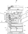
図1〜図4を参照して、本発明の実施の形態に係る画像形成装置100について説明する。図1は、画像形成装置100の外観構成を示す図である。図2は、画像形成装置100の操作ユニットの平面図である。図3は、画像形成装置100の内部構成を簡略化して示す図である。図4は、画像形成装置100の機能ブロック図である。
[Image forming device: function]
An
これらの図1〜図4を参照して、画像形成装置100は、原稿読取部102、画像形成部104、給紙部106、排紙処理装置108、および操作ユニット120を備える。操作ユニット120は、図1および図2に示すように、タッチパネルディスプレイ130と表示操作部140とで構成される。タッチパネルディスプレイ130は、液晶パネル等で構成された表示パネル132と、表示パネル132に重ねて配置されたユーザの指で押圧された位置を検出するタッチパネル134とで構成される。表示操作部140は、表示灯142と、電源キー144と、省エネルギキー(以下「省エネキー」と記載)146と、動作モードを選択するホーム画面へタッチパネルディスプレイ130の表示画面を戻すためのホームキー148とで構成される。
1 to 4, the
このように本実施の形態に係る画像形成装置100は、主たる操作デバイスとしてタッチパネルディスプレイ130を備えるとともに、ハードウェアボタンおよび表示灯により構成される表示操作部140を備える。表示操作部140のキー(電源キー144、省エネキー146、ホームキー148)は、タッチパネルディスプレイ130により構成されるソフトウェアボタンと対比して、ハードウェアボタンとして構成される点が特徴である。なお、画像形成装置100は、このような構成の表示操作部140を備えるものに限定されず、表示操作部140は複数のハードウェアボタンを備えるものであって、それらの複数のハードウェアボタンの中のホームキー148を押下すると、(ホーム画面が表示されていない)タッチパネルディスプレイ130にホーム画面を表示するものであればよい。タッチパネルディスプレイ130に表示されたホーム画面においてユーザが動作モードを選択すると、選択された動作モードにおける初期画面に切り換わるものであれば構わない。このような画像形成装置100の動作モードについて説明する。
As described above, the
−コピーモード−
以下において、コピーモードでの動作説明を行なう。このコピーモードにおいては、主として、原稿読取部(以下、スキャナ部と記載する場合がある。)102および画像形成部104が動作する。
-Copy mode-
Hereinafter, the operation in the copy mode will be described. In this copy mode, a document reading unit (hereinafter sometimes referred to as a scanner unit) 102 and an
画像形成装置100においては、原稿載置台に置かれた原稿が原稿読取部102により画像データとして読取られ、読取られた画像データが図4に示すマイクロコンピュータ等から構成されるCPU300に入力され、ここで画像データに各種の画像処理が施され、この画像データが画像形成部104へと出力される。
In the
画像形成部104は、画像データによって示される原稿の画像を記録媒体(多くの場合、記録用紙)に印刷するものであって、感光体ドラム222、帯電装置224、レーザスキャンユニット(以下、「LSU」と称する。)226、現像装置228、転写装置230、クリーニング装置232、定着装置234、および図示しない除電装置等を備えている。
The
画像形成部104には、主搬送路236および反転搬送路238が設けられており、給紙部106から給紙されてきた記録用紙が主搬送路236に沿って搬送される。給紙部106は、用紙カセット240に収納された記録用紙、または手差トレイ242に載置された記録用紙を1枚ずつ引出して記録用紙を画像形成部104の主搬送路236へと送り出す。
The
画像形成部104の主搬送路236に沿って記録用紙が搬送されている途中で、記録用紙が感光体ドラム222と転写装置230との間を通過し、さらに定着装置234を通過して、記録用紙に対する印刷が行なわれる。
While the recording paper is being conveyed along the
感光体ドラム222は、一方向に回転し、その表面は、クリーニング装置232と除電装置によりクリーニングされた後、帯電装置224により均一に帯電される。
The
LSU226は、印刷対象の画像データに基づいてレーザ光を変調し、このレーザ光によって感光体ドラム222の表面を主走査方向に繰返し走査して、静電潜像を感光体ドラム222の表面に形成する。
The
現像装置228は、トナーを感光体ドラム222の表面に供給して静電潜像を現像し、トナー像を感光体ドラム222の表面に形成する。
The developing
転写装置230は、当該転写装置230と感光体ドラム222との間を通過していく記録用紙に感光体ドラム222の表面のトナー像を転写する。
The
定着装置234は、記録用紙を加熱するための加熱ローラ248と、記録用紙を加圧するための加圧ローラ250とを含む。記録用紙は、加熱ローラ248によって加熱され、かつ、加圧ローラ250によって加圧されることによって、記録用紙上に転写されたトナー像が記録用紙に定着される。この定着装置234へ供給される電力によりヒータを温めて加熱ローラ248の温度が定着に適した温度になるように制御されている。なお、省エネモードに移行すると、たとえば、このヒータへ供給される電力が停止されたり削減されたりする。
The fixing
主搬送路236と反転搬送路238との接続位置には、分岐爪244が配設されている。記録用紙の片面のみに印刷が行なわれる場合は、分岐爪244が位置決めされ、この分岐爪244により定着装置234からの記録用紙が排紙トレイ246または排紙処理装置108の方へと導かれる。
A branching
記録用紙の両面に印刷が行なわれる場合は、分岐爪244が所定方向に回動されて記録用紙が反転搬送路238の方へと導かれる。記録用紙は、反転搬送路238を通過して、その表裏を反転されて主搬送路236へと再び搬送され、主搬送路236の再度の搬送途中で、その裏面への印刷が行なわれて排紙トレイ246または排紙処理装置108の方へと導かれる。
When printing is performed on both sides of the recording paper, the branching
上述のようにして印刷された記録用紙は、排紙トレイ246または排紙処理装置108の方へと導かれて排紙トレイ246に排出され、または排紙処理装置108の各排紙トレイ110のいずれかに排出される。
The recording paper printed as described above is guided toward the
排紙処理装置108では、複数の記録用紙を各排紙トレイ110に仕分けして排出する処理、各記録用紙にパンチングする処理、および各記録用紙にステープルする処理を施す。たとえば、複数部の印刷物を作成する場合は、各排紙トレイ110に印刷物の一部ずつが割り当てられるように、各記録用紙を各排紙トレイ110に仕分けして排出し、排紙トレイ110毎に、排紙トレイ110上の各記録用紙にパンチング処理またはステープル処理を施して印刷物を作成する。
In the paper
−ファクシミリモード−
以下において、ファクシミリモードでの動作説明を行なう。このファクシミリモードにおいては、主として、送信動作は原稿読取部(スキャナ部)102およびFAX通信部160が動作することにより、受信動作はFAX通信部160および画像形成部104が動作する。
-Facsimile mode-
Hereinafter, the operation in the facsimile mode will be described. In this facsimile mode, the document reading unit (scanner unit) 102 and the
・送信動作
画像形成装置100においては、ファクシミリモードを指定して、原稿載置台に置かれた原稿が原稿読取部102により画像データとして読取られ、読取られた画像データが図4に示すマイクロコンピュータ等から構成されるCPU300に入力され、ここで画像データに各種の画像処理が施され、この画像データがFAX通信部(図4のFAX通信部160)へと出力される。
Transmission Operation In the
送信側の画像形成装置100のFAX通信部160は、指定された送信側の回線を指定された送信先に接続して、画像データをファクシミリ通信規格に合致した通信データへ変換して、受信側のファクシミリ装置(たとえばファクシミリ機能を備えた画像形成装置100)へ送信する。
The
・通信動作
回線が接続されると、受信側の画像形成装置100のFAX通信部160は、送信側の画像形成装置100のFAX通信部160からの通信要求信号を検出して、応答信号を送信する。その後、たとえば、FAX通信部160は、送信側および受信側で互いに実装されている能力情報の受渡しを行ない利用可能な最大能力での通信速度および画像データの符号化・符号訂正方式などを決定してモデムの通信方式を設定する。この通信方式にあわせた画像信号形式を用いて、送信側の画像形成装置100のFAX通信部160から受信側の画像形成装置100のFAX通信部160へデータを送信する。送信が終了すると回線が切断される。
Communication operation When the line is connected, the
・受信動作
受信側の画像形成装置100のFAX通信部160は、受信したデータを画像データに変換して、画像形成部104へ送る。なお、受信したデータを画像データへ変換するのは画像形成部104であっても構わない。画像形成部104は、上述したコピーモードにおける動作と同じように、受信したデータから変換された画像データによって示される原稿の画像を記録用紙に印刷する。
Reception Operation The
−ドキュメントファイリングモード−
以下において、ドキュメントファイリングモードでの動作説明を行なう。このドキュメントファイリングモードにおいては、主として、原稿読取部(スキャナ部)102および画像形成部104が動作する。
-Document filing mode-
Hereinafter, the operation in the document filing mode will be described. In the document filing mode, the document reading unit (scanner unit) 102 and the
画像形成装置100においては、原稿載置台に置かれた原稿が原稿読取部102により画像データとして読取られ、読取られた画像データがCPU300に入力され、ここで画像データに各種の画像処理が施される。この画像データが、この画像形成装置100が備える記憶装置(後述するハードディスク302)に記憶される。
In the
記憶された画像データは、ユーザによりファイル名が指定されて、ハードディスクから読出されて、上述したコピーモードと同じ動作で記録用紙に印刷される。 The stored image data is read from the hard disk with a file name designated by the user, and printed on a recording sheet by the same operation as the copy mode described above.
−メールモード(スキャンtoメール)−
以下において、メールモードでの動作説明を行なう。このメールモードにおいては、主として、原稿読取部(スキャナ部)102およびネットワークインターフェイス304が動作する。
-Mail mode (scan to mail)-
The operation in the mail mode will be described below. In this mail mode, the document reading unit (scanner unit) 102 and the
なお、このMFP300が備える画像通信モードとして、FAX通信部160を介して画像データを公衆回線により送受信する上述したファクシミリモード、および、ネットワークインターフェイス304を介して画像データを電子メールに添付する形式でインターネット回線により送受信する電子メール通信モード(メールモード)がある。このほかに、ネットワークインターフェイス304を介して画像データをインターネット回線により送受信するインターネットファクシミリモード、または、ネットワーク回線を用いて画像データを特定のパーソナルコンピュータ(PC)のフォルダに転送する画像転送モード(スキャンtoPCフォルダ)等を備えていても構わない。
As the image communication mode provided in the
画像形成装置100においては、原稿載置台に置かれた原稿が原稿読取部102により画像データとして読取られ、読取られた画像データがCPU300に入力され、ここで画像データに各種画像処理が施される。この画像データが電子メールに添付されて送信される。
In the
ファクシミリモードでは、送信先の電話番号が指定されるのに対して、メールモードでは、送信先のメールアドレスが指定される点が異なる。 In the facsimile mode, the telephone number of the destination is designated, whereas in the mail mode, the destination mail address is designated.
[画像形成装置:制御ブロック構成]
図4を参照して、画像形成装置100はさらに、コピーモード、ファクシミリモード、ドキュメントファイリングモード、およびメールモードに関する機能の設定が可能な操作ユニット120と、プログラム等を記憶するためのROM306と、通電が遮断された場合であってもプログラムおよびデータ等を記憶可能な不揮発性記憶領域であるハードディスク302と、プログラムを実行する際の記憶領域を提供するためのRAM(Random Access Memory)308とを含む。
[Image forming apparatus: control block configuration]
Referring to FIG. 4,
画像形成装置100はさらに、原稿読取部102、画像形成部104、FAX通信部160、操作ユニット120、ROM306、ハードディスク302、およびRAM308に接続されるバス310と、バス310に接続された、画像形成装置としての一般的機能を実現するためのCPU300とを含む。
The
ハードディスク302には、この画像形成装置100でスキャンした原稿の画像データのファイルが、フォルダ別に、保存日時および保存ユーザ名ととともに記憶されている。また、ハードディスク302には、各動作モードの初期画面データが記憶されている。
The
ROM306には、画像形成装置100の動作を制御するのに必要なプログラムおよびデータ等が記憶されている。このROM306にプログラムとともに記憶するデータとして、各動作モードの初期画面データを記憶するようにしても構わない。CPU300は、ROM306に格納されているプログラムおよびデータに従って画像形成装置100の制御を行なうとともに画像形成装置100の各機能に関する制御を実行する。
The
図4に示すように、この画像形成装置100のFAX通信部160には、画像データの送受信用に公衆回線が接続され、ネットワークインターフェイス304にはネットワーク回線が接続されている。このネットワーク回線には、この画像形成装置100をネットワーク対応のプリンタとして使用するコンピュータ等が接続されたり、インターネットを介して指定されたURL(Uniform Resource Locator)により特定されるコンピュータ等が接続されたりする。このようにインターネットに接続されると、画像形成装置100は、インターネットを介して、必要な情報を取得することができる。
As shown in FIG. 4, a public line is connected to the
RAM308は、CPU300による演算および処理の結果を一時的に記憶するワーキングメモリとしての機能と、画像データを記憶するフレームメモリとしての機能とを提供する。
The
原稿読取部102、画像形成部104、操作ユニット120を構成するタッチパネルディスプレイ130および表示操作部140、ならびにROM306、ハードディスク302、およびRAM308に対する制御は、CPU300が所定のプログラムを実行することにより行なわれる。なお、操作ユニット120は、入出力インターフェイスを介してCPU300と通信する。
Control of the
操作ユニット120は、ユーザが目視しやすいように傾斜して設けられた板状のパネルで構成される。操作ユニット120の表面には、その左側の領域にタッチパネルディスプレイ130が、右側の領域に表示操作部140(表示灯142ならびにハードウェアボタンである電源キー144、省エネキー146およびホームキー148)が、備えられている。タッチパネルディスプレイ130および表示操作部140は、操作ユニット120が全体として一体となるように構成されている。
The
上述したように、このタッチパネルディスプレイ130は、表示パネル132と、表示パネル132に重ねて配置されたタッチパネル134とで構成される。このタッチパネルディスプレイ130においては、表示パネル132に、この画像形成装置100における動作モードを選択するホーム画面、この画像形成装置100の現在の状態、宛先指定状況、ジョブの処理状況等が表示される。表示パネル132の表示領域上にはソフトウェアボタンである選択ボタンが表示され、この選択ボタンの表示されている領域を指で押すと、タッチパネル134がその押された位置を検出する。プログラム上で、選択ボタンの表示位置とタッチパネル134が押された位置とを照合することにより、画像形成装置100の動作モード選択、機能設定および動作指示等が行なわれる。この画像形成装置100は、このようなタッチ操作(ユーザによる押圧位置に基づくコマンド入力操作)に加えて、上述したジェスチャー操作(ユーザによる操作軌跡に基づくコマンド入力操作)にも対応している。
As described above, the
また、表示操作部140の表示灯142は、たとえばLED(Light Emitting Diode)で構成され、CPU300により点灯/消灯(/点滅)が制御される。主電源スイッチとは別に設けられた電源キー144をユーザが押下すると、この画像形成装置100が待機モード(たとえば主電源がオンの状態でFAX受信動作のみ可能)から通常モードへ移行して、この画像形成装置100の全ての動作モードが使用できるようになる。この状態に連動して表示灯142が点灯する。さらに、ユーザが操作しない時間が予め定められた時間を経過したり、省エネキー146をユーザが押下したりすると、この画像形成装置100が通常モードから省エネモードへ移行して、この画像形成装置100の一部の動作モードしか使用できないようになる。この状態に連動して表示灯142が点滅する。さらに、この省エネモードのときに、省エネキー146をユーザが押下すると、この画像形成装置100が省エネモードから通常モードへ移行する。ホームキー148は、タッチパネルディスプレイ130の表示を初期状態(ホーム画面)へ戻すためのハードウェアボタンである。なお、電源キー144および省エネキー146を押下したときの処理はこれらに限定されるものではないが、ホームキー148を押下したときの処理は特定の画面に遷移するという範囲で限定される。
Further, the
図1および図2を参照して、操作ユニット120の平面的な配置について詳しく説明する。操作ユニット120の上面の大部分が長方形のタッチパネルディスプレイ130の表示領域であって、タッチパネルディスプレイ130の右の短辺側に表示操作部140(表示灯142、電源キー144、省エネキー146およびホームキー148)が、備えられる。
The planar arrangement of the
図2に示すように、ホームキー148の外観的特徴として、他のハードウェアボタンよりも、(1)タッチパネルディスプレイ130のより近くに配置され、(2)その大きさ(操作ユニット120の上面に投影される面積)が大きく、(3)その形状が縦長方形であって、(4)タッチパネルディスプレイ130との一体性を有する点である。
As shown in FIG. 2, as an external feature of the
なお、(3)における形状の特徴により、タッチパネルディスプレイ130の短辺と対向する長さ(近接長、隣接長)を長くでき、ホームキー148とタッチパネルディスプレイ130との一体性を強調できる。すなわち、ホームキー148がタッチパネルディスプレイ130の左右側に設けられる場合には、ホームキー148の形状は縦長方形として、ホームキー148がタッチパネルディスプレイ130の上下側に設けられる場合には、ホームキー148の形状は横長方形として、ホームキー148とタッチパネルディスプレイ130との一体性を強調している。(4)における一体性とは、たとえば、長方形のタッチパネルディスプレイ130の周縁に配置される部材(タッチパネルディスプレイ130の周縁を押下する筐体等であってもよいし、筐体に限定されず線画や凹凸を備えた部材であっても構わない)が、ホームキー148の近傍でホームキー148を取り囲むようにホームキー148側へ膨らんだデザインを備える。これらにより、タッチパネルディスプレイ130とホームキー148との一体感をユーザに訴求できて、これらのデバイス(表示デバイスと操作デバイス)の間に成立する関連性を創出できるとともに、ホームキー148を押下しやすいという効果がある。
Note that due to the shape feature in (3), the length (proximity length, adjacent length) facing the short side of the
さらに、この操作ユニット120の上面全体は、無彩色(黒)に統一されている。これにより、画像形成装置100が省エネモードであるときなど、画像形成装置100の状態を表す表示灯142による表示状態が確認しやすくなる点で好ましい。特に、タッチパネルディスプレイ130が大型になる場合には省エネルギー対策を考慮する必要があり、操作ができない状態で待機させることに対応できるように、少なくとも電源キー144および省エネキー146をハードウェアボタンとして別に設けている。なお、タッチパネルディスプレイ130の表示領域の部分的な表示(通電)は不可能であるので、省エネモードにおいてはタッチパネルディスプレイ130には何も表示されない黒一色となる。この点で、タッチパネルディスプレイ130および操作ユニット120の上面のパネル筐体が黒一色になるので、表示灯142を目立たせることができる。
Further, the entire upper surface of the
電源キー144および省エネキー146と、ホームキー148との平面的な配置について説明する。図2に示すように、ホームキー148の中心線(Center Line)148Cは、電源キー144の中心線144Cおよび省エネキー146の中心線146Cよりもタッチパネルディスプレイ130側に位置するように、これらの3つのハードウェアボタン(キー)が配置されている。さらに、ホームキー148の外縁線(Edge Line)148Eは、電源キー144の外縁線144Eおよび省エネキー146の外縁線146Eよりもタッチパネルディスプレイ130側に位置するように、これらの3つのハードウェアボタン(キー)が配置されている。なお、ホームキー148の外縁線148Eは、タッチパネルディスプレイ130の反対側の外縁の位置を、電源キー144の外縁線144Eおよび省エネキー146の外縁線146Eは、いずれもタッチパネルディスプレイ130側の外縁の位置を示す。
A planar arrangement of the
図2に示すように、限定されるものではないが、この画像形成装置100においては、ホームキー148の中心線148Cと外縁線148Eとの間に、表示灯142が配置されている。
As shown in FIG. 2, although not limited thereto, in this
なお、表示操作部140のハードウェアボタン(電源キー144、省エネキー146およびホームキー148)には、CPU300により点灯/消灯(/点滅)が制御されるキーランプを埋め込むようにしても構わない。たとえば、このキーランプは、円型のキーの周囲をリング状に光らせたり、キーの中央部を光らせたりする。操作デバイスとしてハードウェアボタンを使用することが許可されているタイミングで(ハードウェアボタンを使用すると処理が実行されるタイミングで)、このキーランプが点灯する。
It should be noted that a key lamp whose lighting / extinguishing (/ flashing) is controlled by the
本実施の形態に係る画像形成装置100においては、上述した4つの動作モード(コピーモード、ファクスモード、ドキュメントファイリングモードおよびメールモード)を備える。タッチパネルディスプレイ130には、それぞれの動作モードにおける機能設定用のソフトウェアボタンと、必要に応じて、画像形成イメージであるプレビューまたは宛先設定用のボタン等が表示される。
The
動作モードが違う場合には、タッチパネルディスプレイ130は、異なる画面が表示される。このような場合であっても、ユーザが要求する情報を容易に見つけることのできるように、タッチパネルディスプレイ130は複数の領域に分割されて(かつその領域の大きさを可変として)、各領域に情報を表示するという本発明の本質的部分を備える。特に、この画像形成装置100においては、主たる表示操作デバイスとして設けられたタッチパネルディスプレイ130のホーム画面において動作モードを選択すると、各動作モードの初期画面が表示される。この初期画面において、(1)基本レイアウトが5つの領域(「システム領域」、「機能選択領域」、「プレビュー領域」、「アクションパネル領域」、「タスクトリガー領域」)に分割されて適切に配置されているので、左上から右下へユーザが操作することにより(このような大型のタッチパネルディスプレイ130を備えない従来機と同じようなユーザの視点の動線および指先の動線が実現されるために)容易に設定が可能で、(2)異なる動作モードであっても5つの領域のそれぞれに表示される概念は同じものであって、動作モードが異なってもユーザが混乱することなく操作が可能である。以下において、このような基本レイアウトの構成について説明する。
When the operation mode is different, the
[基本レイアウト構成]
図5に、この画像形成装置100のタッチパネルディスプレイ130における基本レイアウトを示す。図5を参照して、この基本レイアウトは、横長のタッチパネルディスプレイ130において(たとえば、横1024ピクセル×縦600ピクセル)、最上部に配置されたシステム領域1000、画面中央部に配置されたプレビュー領域3000、プレビュー領域3000の左側に配置された機能設定/確認領域2000(以下、機能選択領域2000と記載する)、プレビュー領域3000の右上部に配置されたアクションパネル領域4000、および、プレビュー領域3000の右下部に配置されたタスクトリガー領域5000で構成される。なお、領域の数は5つに限定されるものではなく、左右の並びもこれに限定されず、ユーザが操作しやすいようにカスタマイズすることができる。また、システム領域1000の位置は最下部であっても構わない。
[Basic layout configuration]
FIG. 5 shows a basic layout of the
システム領域1000には、この画像形成装置100の現時点での状態が表示され、操作中の動作モードのタイトル、画像形成装置100の状況・状態が表示される。たとえば、システム領域1000には、動作モード名、割り込みキー、ログインユーザ名、処理中のジョブ状況、内蔵メモリ使用状態、時刻等が表示される。
In the
機能選択領域2000には、各機能の設定、表示の切り換え、設定の確認のためにユーザにより操作される機能選択メニュー(アイコン、ボタン等)が、アイコンモード、レギュラーモードおよびエキスプレスモードで表示態様を変更して、表示される。アイコンモードにおいては、プレビュー領域3000が最も広くなるように機能選択領域2000には機能設定用のアイコンのみが表示される。エキスプレスモードにおいては、プレビュー領域3000が最も狭くなっても機能選択領域2000には機能を一度に設定できる画面が大きく表示される。レギュラーモードにおいては、プレビュー領域3000の大きさはアイコンモードとエキスプレスモードとの中間の大きさであって、機能選択領域2000には機能設定のアイコンとともに機能名称がテキスト表示される。
In the
これらのアイコンモード、レギュラーモードおよびエキスプレスモードの切り換えはユーザの操作に基づく。すなわち、プレビュー領域3000の大きさが、ユーザの操作に応じて変更して表示される。このように、アイコンは、小さい領域でユーザへの情報を伝達することができるので、全ての機能に対して準備しておいて、プレビュー領域3000が大きく表示できることが好ましい。
Switching between these icon mode, regular mode and express mode is based on the user's operation. That is, the size of the
この機能選択領域2000には、その下部に機能選択領域2000の表示スタイルを変更する変更ボタン群2010を備える。変更ボタン群2010には、アイコンモードで機能選択領域2000を表示するアイコンモード移行ボタン2012、「お気に入り」登録した機能を表示させるお気に入りボタン2014、設定が変更された機能を表示させるチェックボタン2016、選択されている動作モードにおいて設定可能な全ての機能の一覧を表示するリストボタン2018、レギュラーモードで機能選択領域2000を表示するレギュラーモード移行ボタン2020、および、エキスプレスモードで機能選択領域2000を表示するエキスプレスモード移行ボタン2022が配置されている。
The
なお、機能選択領域2000に表示される情報が多い場合には、この機能選択領域2000において上下方向にスクロール可能に情報が表示される。この場合において、この変更ボタン群2010はスクロールされないで、機能選択領域2000の最下部に常に表示される。
If there is a lot of information displayed in the
プレビュー領域3000には、原稿の出力(仕上がり)イメージが表示される。ダミーデータまたはスキャンデータを用いてイメージ表示し、ユーザが仕上がりを指示する毎にプレビュー領域3000に表示されているイメージが変更される。このプレビュー領域3000においては、スキャン前のバーチャルモードでのダミーイメージでの仕上がり表示、スキャン後のスキャンインモードでの実イメージでの仕上がり表示の2つのモードを有し、さらにバーチャルモードには、原稿セット前および原稿セット後の2種類がある。
In
このプレビュー領域3000には、その下部にプレビュー領域3000の表示スタイルを変更するプレビュー変更ボタン群3010を備える。プレビュー変更ボタン群3010には、プレビューを左に90度回転させる左回転ボタン3016、プレビューを右に90度回転させる右回転ボタン3018、ズームバー3020が配置されている。これら以外にも、たとえばカラー変更ボタン3012およびプレビュー操作ボタン3014が配置されている。
The
ここで、左回転ボタン3016を1回タッチ操作するとプレビューが左に90度回転されて、2回タッチ操作するとプレビューが左に180度回転される(上下反転)。また、プレビュー領域に表示された仕上がり原稿イメージをジェスチャー操作しても(指先で原稿イメージを反時計回転方向に180度回転させても)、プレビューが左に180度回転されて上下反転される。
Here, when the
右回転ボタン3018を1回タッチ操作するとプレビューが右に90度回転されて、2回タッチ操作するとプレビューが右に180度回転される(上下反転)。また、プレビュー領域に表示された仕上がり原稿イメージをジェスチャー操作しても(指先で原稿イメージを時計回転方向に180度回転させても)、プレビューが右に180度回転されて上下反転される。
When the
ズームバー3020のプラスボタン3020Aをタッチ操作したり、バー3020Cをプラスボタン3020A側へジェスチャー操作(スライド)したりすると、プレビューが拡大して表示される。また、プレビュー領域に表示された仕上がり原稿イメージをジェスチャー操作しても(指先で原稿イメージをピンチアウト/ピンチオープンさせても)、プレビューが拡大して表示される。
When the
ズームバー3020のマイナスボタン3020Bをタッチ操作したり、バー3020Cをマイナスボタン3020B側へジェスチャー操作(スライド)したりすると、プレビューが縮小して表示される。また、プレビュー領域に表示された仕上がり原稿イメージをジェスチャー操作しても(指先で原稿イメージをピンチイン/ピンチクローズさせても)、プレビューが縮小して表示される。
When the
なお、プレビュー領域3000に表示される原稿イメージのページ数が多い場合には、タッチ操作可能な表示ページ選択ボタン(ページ番号入力ボタン、ページ送りボタン、ページ戻しボタン、単ページ表示ボタン、複数ページ表示ボタン等)を表示するようにしても構わない。なお、原稿イメージをジェスチャー操作(フリック)してもプレビューされる原稿のページ送り、ページ戻しを行なうこともできる。また、プレビュー領域3000に表示される原稿イメージが大きい場合には、タッチ操作またはジェスチャー操作可能なスクロールバーを表示するようにしても構わない。
When the number of pages of the document image displayed in the
アクションパネル領域4000には、操作についての補助・助言・提案についての情報が表示される。このアクションパネル領域4000には、たとえば、あるユーザが特定の機能を選択すると、その機能に関連する機能を表示したり、目的指向でその機能についての他の機能を表示したり、このユーザまたはこのユーザが所属するグループのユーザが過去に組み合わせて選択した機能を「おすすめ機能」として表示したりする。
In the
タスクトリガー領域5000には、その動作モードにおける全ての設定が完了して、この画像形成装置100を実際に動作させるためにユーザにより操作されるトリガー項目が表示される。たとえば、処理を開始させるためのスタートボタン(ソフトウェアボタン)である。なお、印字を伴う動作モード(ファクス送信以外)において、消耗品切れについての情報も、タスクの実行不可に関連するので、この「タスクトリガー領域」に表示される。
In the
この場合において、スタートボタンが押下できる状態の場合にのみ、スタートボタンを表示することも好ましい。スタートボタンが押下できる状態とは、印字を伴う動作モードの場合には、全ての設定が終了してかつ消耗品(記録用紙およびトナー)切れでない状態であって、印字を伴わない動作モードであるファクスモード(送信)の場合には、宛先を含む全ての送信パラメータの設定が終了した状態である。 In this case, it is also preferable to display the start button only when the start button can be pressed. The state in which the start button can be pressed is an operation mode in which all settings are completed and consumables (recording paper and toner) are not exhausted and printing is not performed in an operation mode with printing. In the fax mode (transmission), all transmission parameters including the destination are set.
これらの5領域は、動作モードが変更されても(どの動作モードの初期画面においても)、その配置された位置は変更されない。また、機能選択領域2000(およびプレビュー領域3000)におけるアイコンモード/レギュラーモード/エキスプレスモードの切り換え表示のように、領域はタッチパネルディスプレイ130の画面横方向(長手方向)に伸縮してサイズが変化する。
Even if the operation mode is changed (in the initial screen of any operation mode), the positions where these five areas are arranged are not changed. In addition, the area is expanded and contracted in the horizontal direction (longitudinal direction) of the screen of the
このような5領域の配置は、従来機におけるユーザインターフェイスをも考慮しつつ、ユーザの視点の動線および操作の動線に着目して配置されている。このような配置により、タッチパネルディスプレイ130において、左上から右下へユーザの視線が動いて、左上から右下へユーザの操作(利き手の指先)が動く。これにより、ユーザフレンドリーな操作が可能という効果が発現される。
Such an arrangement of the five regions is arranged by paying attention to the user's viewpoint flow line and the operation flow line while taking into account the user interface in the conventional machine. With this arrangement, on the
なお、ある動作モードから他の動作モードへ遷移するためには、ホームキー148を押下して、ホーム画面において他の動作モードを選択する。このように、ホーム画面を経由して、動作モードが切り換えられる。
In order to change from one operation mode to another operation mode, the
このように、この画像形成装置100においては、ユーザによりホームキー148が押下されると、ホーム画面が表示されるタッチパネルディスプレイ130を備える。このような表示処理は、上述したハードウェア構成を用いて実行されるソフトウェアにより実現される。
As described above, the
すなわち、基本的には、どのような画面がタッチパネルディスプレイ130に表示されている場合であっても、画像形成装置100のCPU300は、ホームキー148が押下されたことを検出すると、タッチパネルディスプレイ130にホーム画面を表示するプログラムを実行する。このようなプログラムと並行して、画像形成装置としての一般的機能を実現するプログラムを実行する。しかしながら、そのプログラムは、本発明の本質的部分とは直接関係するものではないので、その詳細についてはここでは説明しない。なお、ホームキー148を長押ししたり、2度押ししたりすることにより、画像形成装置100の制御(特にタッチパネルディスプレイ130の表示制御)を変更することは排除されない。
That is, basically, no matter what screen is displayed on the
[動作]
以上のような構造およびプログラムに基づく、本実施の形態に係る画像形成装置100の動作について、図6および図7に示すタッチパネルディスプレイ130の表示例を用いて説明する。
[Operation]
The operation of
−ホーム画面表示動作−
ユーザが、この画像形成装置100の電源キー144を押下してウォームアップが完了するまでは、タッチパネルディスプレイ130にウォームアップ画面が表示される。このとき、ウォームアップ画面として、画像形成装置100がシステムチェック中でも表示できる情報であって、この画像形成装置100を使用しようとしているユーザに有益な情報を準備しておいて、タッチパネルディスプレイ130に表示することが好ましい。
-Home screen display operation-
The warm-up screen is displayed on the
ウォームアップが完了すると、タッチパネルディスプレイ130にホーム画面が表示される。このとき、たとえば、タッチパネルディスプレイ130には、図6に示すホーム画面6000が表示される。図6に示すように、ホーム画面6000は、上述したレイアウト構成の5領域の全ての領域が表示されるものでなく、5領域とは関係なくタッチパネルディスプレイ130の大部分に動作モードを選択するためのアイコン(動作モードを模したアイコン)が表示される。なお、このホーム画面6000に表示されるアイコンの数は、たとえば、「多い」、「標準」、「少ない」の3段階程度にカスタマイズすることが可能である。
When the warm-up is completed, the home screen is displayed on the
図6を参照して、ホーム画面6000は、上述したシステム領域に対応するホームシステム領域6100と、アイコン表示領域6200と、アイコン表示切換タブボタン6300と、メモ表示領域6400とで構成される。
Referring to FIG. 6,
ホームシステム領域6100には、ホーム画面を示すアイコンが表示されるエリア6102、表示されている画面の名称が表示されるエリア6104、ログインユーザ名が表示されるエリア6106、ログアウトボタン(ソフトウェアボタン)が表示されるエリア6108、現在時刻が表示されるエリア6110が配置されている。
The
アイコン表示領域6200には、動作モードを模したアイコン6210〜アイコン6274がその動作モードの名称または略称とともに表示される。なお、動作モードの名称または略称は必須ではない。本実施の形態においては、少なくとも4つの動作モード(コピーモード、ファクスモード、ドキュメントファイリングモードおよびメールモード)を備えるため、コピーモードを選択するためのアイコン6242、ファクスモードを選択するためのアイコン6232、ドキュメントファイリングモードを選択するためのアイコン6254、メールモードを選択するためのアイコン6240が、アイコン表示領域6200に表示される。図6においては、これら以外の動作モードを選択するためのアイコン、他の設定モード(たとえばシステム設定、言語設定)を選択するためのアイコンおよび他の画面を表示するためのアイコン(たとえばジョブ状況)も表示している。
In the
図6に示すように、アイコン表示領域6200においては、中央列のアイコン(たとえばアイコン6240、アイコン6242、アイコン6244)は、それらの左右のアイコン(たとえばアイコン6240に対するアイコン6230およびアイコン6250、アイコン6242に対するアイコン6232およびアイコン6252、アイコン6244に対するアイコン6234およびアイコン6254)よりも大きく表示される。また、このアイコン表示領域6200においては、中央段のアイコン(たとえばアイコン6232、アイコン6242、アイコン6252)は、それらの上下のアイコン(たとえばアイコン6232に対するアイコン6230およびアイコン6234、アイコン6242に対するアイコン6240およびアイコン6244、アイコン6252に対するアイコン6250およびアイコン6254)よりも大きく表示される。このように、このアイコン表示領域6200においては、アイコンの大きさは、中央部の中央段に配置されるアイコンの大きさが最も大きく、かつ、左右対称および上下対称になるように表示される。
As shown in FIG. 6, in the
また、タッチパネルディスプレイ130の画面に表示されたアイコン表示領域6200を、ユーザが指先で左にフリック操作すると、画面に表示されるアイコンが、矢示6010で示す方向へ流れるように移動し、ユーザが指先で右にフリック操作すると、画面に表示されるアイコンが、矢示6020で示す方向へ流れるように移動する。このときの移動量は、フリック操作における指先の移動幅により定めても良いし、1回のフリック操作に対して予め設定される所定量としても良い。また、このアイコン表示領域6200は、仮想円筒に表示されたように構成すると、アイコンを無端状で切り換えて表示させることができる。
Further, when the user flicks the
メモ表示領域6400には、この画像形成装置100のユーザ全般に知らせたいメンテナンス情報等が表示される。
In the
−コピーモードの初期画面表示動作−
図6に示すアイコン6242をユーザが指先でタッチ操作、タップ操作またはダブルタップ操作すると、動作モードが選択されたと判定され、選択された動作モードがコピーモードであると、タッチパネルディスプレイ130にコピーモードの初期画面が表示される。このとき、たとえば、タッチパネルディスプレイ130には、図7に示すコピーモード初期画面7100が表示される。図7に示すように、コピーモード初期画面7100は、上述したレイアウト構成の5領域に分割されて情報が表示される。
-Initial screen display operation in copy mode-
When the user touches, taps, or double-taps the icon 6242 shown in FIG. 6 with the fingertip, it is determined that the operation mode is selected. If the selected operation mode is the copy mode, the
図7を参照して、コピーモード初期画面7100のシステム領域1000には、選択されている動作モード(ここではコピーモード)を示すエリア1102、選択された動作モードに付随するサブ情報を表示するエリア1104、ログインユーザ名を表示するエリア1106、ログアウトボタン(ソフトウェアボタン)が表示されるエリア1108、現在実行中のジョブ状況を表示するエリア1110、ジョブ状況に関係するボタン(ソフトウェアボタン)が表示されるエリア1112、通信状態が表示されるエリア1114、現在時刻が表示されるエリア1116が配置されている。
Referring to FIG. 7, in
エリア1102には、動作モードを示す名称または/およびアイコンが表示される。このエリア1102をタッチ操作、タップ操作またはダブルタップ操作すると、動作モードを示すメニューがプルダウン表示されて動作モードを切り換えることができるようにすることも好ましい(他の動作モードにおいても同じ)。
In
エリア1104には、サブ情報として、割り込みキー(ソフトウェアボタン)が表示される。この割り込みキーをタッチ操作、タップ操作またはダブルタップ操作すると、コピーモードにおいて割り込み処理を実行することができる。
In
エリア1106には、現在実行中のジョブ状況がアイコンで表示される。このジョブ状況をタッチ操作、タップ操作またはダブルタップ操作すると、詳細なジョブ状況情報が表示される。さらに、エリア1112には、選択されたジョブを停止させるボタン等を表示することも好ましい。
In the
コピーモード初期画面7100の機能選択領域2000には、コピーモードにおいてユーザが選択できる機能選択メニューおよび上述した変更ボタン群2010が表示されている。図7に示す画面では、レギュラーモードで機能選択メニューが表示されている。
In the
図7に示すように、レギュラーモードで表示される機能選択メニューは、アイコン群2100とテキスト群2120とで構成される。この機能選択領域2000に表示される機能選択メニューとして、コピー部数を設定するアイコン2102および設定された内容を表示するテキスト2122、カラーモードを設定するアイコン2104および設定された内容を表示するテキスト2124、コピー濃度を設定するアイコン2106および設定された内容を表示するテキスト2126、コピー倍率を設定するアイコン2108および設定された内容を表示するテキスト2128、原稿の種類を設定するアイコン2110および設定された内容を表示するテキスト2130、用紙の種類を設定するアイコン2112および設定された内容を表示するテキスト2132、画像を編集するアイコン2114および設定された内容を表示するテキスト2134、レイアウトを編集するアイコン2116および設定された内容を表示するテキスト2136が表示されている。
As shown in FIG. 7, the function selection menu displayed in the regular mode includes an
なお、上述したように、これらの機能設定メニューにおけるさらなる項目は、変更ボタン群2010の表示位置を固定した状態で、上下方向にスクロール可能に表示することができる。そして、上下方向に隠れて表示されていない項目を含めて機能設定メニューの表示項目を切り換えることは、タッチ操作(スクロール操作)でもジェスチャー操作(上下方向へフリック操作)のいずれの操作でも可能である。
As described above, further items in these function setting menus can be displayed in a vertically scrollable manner with the display position of the
ここで、画像編集とは、1ページの原稿に対する画像編集であって、さらに下位の階層メニューとして、枠消去、印字メニュー、ウォータマーク、ユーザスタンプ等があり、レイアウト編集とは、複数ページの原稿に対する画像編集であって、さらに下位の階層メニューとして、ページ集約、とじしろ、ページ移動、センタリング等がある。これらのさらなる下位メニューは、アイコン2102〜アイコン2116またはテキスト2122〜テキスト2136をタッチ操作、タップ操作またはダブルタップ操作すると、タッチパネルディスプレイ130に表示される。
Here, image editing refers to image editing for a one-page document, and further lower layer menus include frame deletion, print menu, watermark, user stamp, etc., and layout editing refers to a multi-page document. In the image editing, lower level hierarchical menus include page aggregation, margin, page movement, centering, and the like. These further lower menus are displayed on the
コピーモード初期画面7100のプレビュー領域3000には、原稿の出力(仕上がり)イメージ3100および上述したプレビュー変更ボタン群3010が配置されている。このとき、ダミーデータまたはスキャンデータを用いてイメージ3100が表示され、ユーザが機能選択領域2000の機能設定メニューを変更する毎に、イメージ3100が変更されてプレビュー領域3000に表示される(プレビューの表示が変更)。
In the
コピーモード初期画面7100のアクションパネル領域4000には、コピー操作についての補助・助言・提案についての情報が表示されている。ここでは、図7に示すように、このユーザが選択したコピーモードにおけるおすすめ機能が表示される。このとき、アクションパネル領域4000は、表示されている情報の内容を示すエリア4100、それ自体がソフトウェアボタンとしておすすめ機能をテキスト表示するエリア4102〜エリア4106が配置されている。
In the
エリア4102をタッチ操作、タップ操作またはダブルタップ操作すると、省エネコピーについてのさらに詳細な情報がプルダウン表示される。たとえば、このとき、両面印刷すると用紙を節約できますというテキストとともに両面コピーの機能設定画面へ遷移するソフトウェアボタンと、複数の原稿を集約して印刷すると用紙を節約できますというテキストとともにページ集約の機能設定画面へ遷移するソフトウェアボタンと、本のように綴じられるように印刷することができますというテキストとともに中とじの機能設定画面へ遷移するソフトウェアボタンとが、表示される。
When the
コピーモード初期画面7100のタスクトリガー領域5000には、実行ボタン群5100が表示される。この実行ボタン群5100として、原稿をスキャンして画像データを取得するように画像形成装置100を作動させるスキャンインキー(ソフトウェアボタン)5102、設定した機能をクリアするクリアオールキー(ソフトウェアボタン)5104、原稿をスキャンしてモノクロコピーを実行するように画像形成装置100を作動させるモノクロスタートキー(ソフトウェアボタン)5106、原稿をスキャンしてカラーコピーを実行するように画像形成装置100を作動させるカラースタートキー(ソフトウェアボタン)5108が配置されている。
An
このように、5つの領域に分割して情報が表示されたコピーモード初期画面7100において、ユーザが様々な要求を入力する。動作モードはコピーモードに限定されないが、動作モードを選択した後に、その動作モードにおける要求をユーザが入力している過程において、ユーザが操作に戸惑うことが発生し得る。この場合、ユーザが、タッチパネルディスプレイ130の表示をホーム画面に戻して、動作モードの選択からやり直したいと感じる場合がある。ユーザがこのように感じると、操作ユニット120に設けられたホームキー148をユーザが押下する。このとき、ユーザは、タッチパネルディスプレイ130に一体感を創出しているホームキー148を容易に見つけることができる。
In this way, the user inputs various requests on the copy mode
ユーザがホームキー148を押下すると、図7に示す画面が図6に示す画面に遷移する。なお、このとき、ユーザが途中まで要求した設定(たとえば図7におけるコピー部数が10部という設定)は、保持しても破棄しても、いずれでも構わない。保持した場合には、図7に示す画面が図6に示す画面に遷移した後に、図6に示すアイコン6242をユーザが再度指先でタッチ操作、タップ操作またはダブルタップ操作すると、タッチパネルディスプレイ130にコピーモードの初期画面が表示されるとともに、保持した設定内容が表示されるようにすることができる。
When the user presses the
[効果]
以上のようにして、本実施の形態に係る画像形成装置においては、動作モードを選択するホーム画面へタッチパネルディスプレイの表示を切り換えるためのホームキーが、タッチパネルディスプレイと一体感を創出するように備えられている。詳しくは、ホームキーは、(1)他のハードウェアボタン(電源キーおよび省エネキー)よりもタッチパネルディスプレイの近くに配置され、(2)他のハードウェアボタンよりも大きく、(3)ホームキーの形状は縦長方形であって(タッチパネルディスプレイは横長)、(4)ホームキーの周囲の筐体部分とタッチパネルディスプレイの周囲の筐体部分とが同じように窪んだ構造を備える。このようなホームキーの形状、配置および構造により、タッチパネルディスプレイとホームキーとは一体性を有するので、タッチパネルディスプレイの表示をホーム画面に戻したいユーザは、ホームキーを容易に見つけることができる。このため、ユーザが要求するホーム画面表示についての操作性を向上させることができる。
[effect]
As described above, in the image forming apparatus according to the present embodiment, the home key for switching the display of the touch panel display to the home screen for selecting the operation mode is provided so as to create a sense of unity with the touch panel display. ing. Specifically, the home key is arranged closer to the touch panel display than (1) other hardware buttons (power key and energy saving key), (2) larger than the other hardware buttons, and (3) the home key The shape is a vertical rectangle (the touch panel display is horizontally long), and (4) the housing portion around the home key and the housing portion around the touch panel display are similarly recessed. Because of the shape, arrangement and structure of the home key, the touch panel display and the home key are integrated, so that a user who wants to return the touch panel display to the home screen can easily find the home key. For this reason, the operativity about the home screen display which a user requests | requires can be improved.
<第1の変形例>
以下に、図8を参照して、本実施の形態に係る画像形成装置についての第1の変形例を説明する。本変形例に係る画像形成装置は、操作ユニット1120における電源キー1144および省エネキー1146と、ホームキー1148との配置関係が上述した実施の形態(図2)とは異なる。これ以外については、本変形例と上述した実施の形態とは同じであるので、それらについての詳細な説明はここでは繰返さない。
<First Modification>
Hereinafter, a first modification of the image forming apparatus according to the present embodiment will be described with reference to FIG. The image forming apparatus according to this modification differs from the above-described embodiment (FIG. 2) in the arrangement relationship between the
図8に示すように、この操作ユニット1120は、その平面の大部分が長方形のタッチパネルディスプレイ130の表示領域であって、タッチパネルディスプレイ130の右の短辺側に表示灯1142、電源キー1144、省エネキー1146およびホームキー1148が、備えられる。図8に示すように、表示灯1142、電源キー1144および省エネキー1146は、左右方向を揃えて配置されている(このように左右を揃える配置に限定されるものではない)。すなわち、電源キー1144の中心線1144Cは、省エネキー1146の中心線と一致する。また、本変形例においては、電源キー1144の大きさと省エネキー1146の大きさとが同じであるので、電源キー1144の外縁線1144Eは、省エネキー1146の外縁線と一致する。
As shown in FIG. 8, the
電源キー1144および省エネキー1146と、ホームキー1148との平面的な配置について説明する。図8に示すように、ホームキー1148の中心線1148Cは、電源キー1144の中心線1144C(省エネキー1146の中心線でもある)よりもタッチパネルディスプレイ130側に位置するように、これらの3つのハードウェアボタン(キー)が配置されている。さらに、ホームキー1148の外縁線1148Eは、電源キー1144の外縁線1144E(省エネキー1146の外縁線でもある)よりもタッチパネルディスプレイ130側に位置するように、これらの3つのハードウェアボタン(キー)が配置されている。なお、ホームキー1148の外縁線1148Eは、タッチパネルディスプレイ130の反対側の外縁の位置を、電源キー1144および省エネキー1146の外縁線1144Eは、タッチパネルディスプレイ130側の外縁の位置を示す。
A planar arrangement of the
なお、限定されるものではないが、図8に示すように、この画像形成装置においては、電源キー1144の中心線1144C(省エネキー1146の中心線でもある)上に、表示灯1142が配置されている。
Although not limited thereto, as shown in FIG. 8, in this image forming apparatus, an
このように、本変形例に係る画像形成装置においても、動作モードを選択するホーム画面へタッチパネルディスプレイの表示を切り換えるためのホームキーが、タッチパネルディスプレイと一体感を創出するように備えられているので、ユーザは、ホームキーを容易に見つけることができる。 Thus, in the image forming apparatus according to the present modification, the home key for switching the display of the touch panel display to the home screen for selecting the operation mode is provided so as to create a sense of unity with the touch panel display. The user can easily find the home key.
<第2の変形例>
以下に、図9を参照して、本実施の形態に係る画像形成装置についての第2の変形例を説明する。本変形例に係る画像形成装置は、操作ユニット2120における電源キー2144および省エネキー2146と、ホームキー2148との配置関係が上述した実施の形態(図2)とは異なる。これ以外については、本変形例と上述した実施の形態とは同じであるので、それらについての詳細な説明はここでは繰返さない。
<Second Modification>
Hereinafter, a second modification of the image forming apparatus according to the present embodiment will be described with reference to FIG. The image forming apparatus according to this modification differs from the above-described embodiment (FIG. 2) in the arrangement relationship between the
図9に示すように、この操作ユニット2120は、その平面の大部分が長方形のタッチパネルディスプレイ130の表示領域であって、タッチパネルディスプレイ130の下の長辺側に表示灯2142、電源キー2144、省エネキー2146およびホームキー2148が、備えられる。図9に示すように、表示灯2142、電源キー2144および省エネキー2146は、上下方向を揃えて配置されている(このように上下を揃える配置に限定されるものではない)。すなわち、電源キー2144の中心線2144Cは、省エネキー2146の中心線と一致する。また、本変形例においても、電源キー2144の大きさと省エネキー2146の大きさとが同じであるので、電源キー2144の外縁線2144Eは、省エネキー2146の外縁線と一致する。
As shown in FIG. 9, the
電源キー2144および省エネキー2146と、ホームキー2148との平面的な配置について説明する。図9に示すように、ホームキー2148の中心線2148Cは、電源キー2144の中心線2144C(省エネキー2146の中心線でもある)よりもタッチパネルディスプレイ130側に位置するように、これらの3つのハードウェアボタン(キー)が配置されている。さらに、ホームキー2148の外縁線2148Eは、電源キー2144の外縁線2144E(省エネキー2146の外縁線でもある)よりもタッチパネルディスプレイ130側に位置するように、これらの3つのハードウェアボタン(キー)が配置されている。なお、ホームキー2148の外縁線2148Eは、タッチパネルディスプレイ130の反対側の外縁の位置を、電源キー2144および省エネキー2146の外縁線2144Eは、タッチパネルディスプレイ130側の外縁の位置を示す。
A planar arrangement of the
なお、限定されるものではないが、図9に示すように、この画像形成装置においては、電源キー2144の中心線2144C(省エネキー2146の中心線でもある)上に、表示灯2142が配置されている。
Although not limited thereto, as shown in FIG. 9, in this image forming apparatus, an
このように、本変形例に係る画像形成装置においても、動作モードを選択するホーム画面へタッチパネルディスプレイの表示を切り換えるためのホームキーが、タッチパネルディスプレイと一体感を創出するように備えられているので、ユーザは、ホームキーを容易に見つけることができる。 Thus, in the image forming apparatus according to the present modification, the home key for switching the display of the touch panel display to the home screen for selecting the operation mode is provided so as to create a sense of unity with the touch panel display. The user can easily find the home key.
なお、上述した変形例を含む実施の形態においては、ハードウェアボタンの中心線の位置関係または外縁線の位置関係により、ホームキーが最もタッチパネルディスプレイ側に設けられていることを説明した。しかしながら、実質的にホームキーが最もタッチパネルディスプレイ側に設けられているものであれば、中心線および外縁線により限定されるものでなくても構わない。 In the embodiment including the above-described modification, it has been described that the home key is provided closest to the touch panel display by the positional relationship of the center line of the hardware button or the positional relationship of the outer edge line. However, as long as the home key is substantially provided on the most touch panel display side, the center key and the outer edge line may not be used.
今回開示された実施の形態は単に例示であって、本発明が上述した実施の形態のみに限定されるわけではない。本発明の範囲は、発明の詳細な説明の記載を参酌した上で、特許請求の範囲の各請求項によって示され、そこに記載された文言と均等の意味および範囲内でのすべての変更を含む。 The embodiment disclosed this time is merely an example, and the present invention is not limited to the embodiment described above. The scope of the present invention is indicated by each of the claims after taking into account the description of the detailed description of the invention, and all modifications within the meaning and scope equivalent to the wording described therein are intended. Including.
100 画像形成装置
120 操作ユニット
130 タッチパネルディスプレイ
132 表示パネル
134 タッチパネル
140 表示操作部
142 表示灯
144 電源キー
146 省エネキー
148 ホームキー
300 CPU
302 ハードディスク
304 ネットワークインターフェイス
306 ROM
308 RAM
310 バス
DESCRIPTION OF
302
308 RAM
310 bus
Claims (7)
ユーザに情報を表示するための表示手段と、
ユーザが要求を入力するための入力手段と、
前記表示手段に特定の情報を表示する要求が前記入力手段から入力されると、前記特定の情報を前記表示手段に表示するための表示制御手段とを含み、
前記入力手段は、複数の要求を入力するために各要求に対応した複数の操作ボタンを含み、
前記複数の操作ボタンの中で、前記特定の情報を表示する要求に対応した1つの操作ボタンが、他のいずれの操作ボタンよりも前記表示手段の最も近くに設けられ、
前記操作機器は、複数の動作モードの中からユーザの操作により選択された1の動作モードで作動する制御対象装置に備えられ、
前記特定の情報は、複数の動作モードの中から1の動作モードを選択するためのモード選択情報であり、
複数の前記動作モードは、コピーモード及びファクスモードを含み、
前記モード選択情報は、前記コピーモードを選択するための情報、及び前記ファクスモードを選択するための情報を含み、
前記複数の操作ボタンは、前記特定の情報を表示する要求に対応した操作ボタンに加えて、前記制御対象装置へ供給される電力を制御する操作ボタンを含み、
前記操作機器は、前記表示手段に重ねて配置された、ユーザの指先が触れた位置に基づき要求を検出するタッチパネルをさらに含み、
前記特定の情報を表示する要求に対応した操作ボタンおよび前記制御対象装置へ供給される電力を制御する操作ボタン以外に対するユーザの操作は、前記タッチパネルにより検出される、操作機器。 An operation device provided in a control target device that is operated by a user operation,
Display means for displaying information to the user;
An input means for the user to enter the request;
When a request to display specific information on the display means is input from the input means, the display control means for displaying the specific information on the display means,
The input means includes a plurality of operation buttons corresponding to each request in order to input a plurality of requests,
Among the plurality of operation buttons, one operation button corresponding to the request to display the specific information is provided closer to the display means than any other operation button,
The operating device is provided in a control target device that operates in one operation mode selected by a user operation from a plurality of operation modes,
The specific information, Ri mode selection information der for selecting an operation mode of one from a plurality of operation modes,
The plurality of operation modes include a copy mode and a fax mode,
The mode selection information includes information for selecting the copy mode and information for selecting the fax mode,
The plurality of operation buttons include an operation button for controlling power supplied to the device to be controlled, in addition to an operation button corresponding to a request to display the specific information,
The operating device further includes a touch panel that is arranged over the display means and detects a request based on a position touched by a user's fingertip,
An operation device in which an operation of a user other than an operation button corresponding to a request to display the specific information and an operation button for controlling power supplied to the control target device is detected by the touch panel .
前記略長方形のいずれかの辺に対向して、前記複数の操作ボタンが設けられ、
前記複数の操作ボタンの中で、前記特定の情報を表示する要求に対応した操作ボタンが前記いずれかの辺に対向するように設けられた、請求項1に記載の操作機器。 The display means includes a horizontally long and substantially rectangular flat display area,
The plurality of operation buttons are provided facing either side of the substantially rectangular shape,
The operating device according to claim 1, wherein among the plurality of operating buttons, an operating button corresponding to a request for displaying the specific information is provided to face any one of the sides.
Image processing apparatus including an operation device according to any of claims 1 to 5.
Priority Applications (8)
| Application Number | Priority Date | Filing Date | Title |
|---|---|---|---|
| JP2010033289A JP5199295B2 (en) | 2010-02-18 | 2010-02-18 | Operating device, electronic device including the operating device, and image processing apparatus |
| US13/022,712 US9030679B2 (en) | 2010-02-18 | 2011-02-08 | Operation console with enhanced configuration of operation buttons for command inputs, and electronic device and image processing apparatus provided with the operation console |
| CN2011100402665A CN102164221A (en) | 2010-02-18 | 2011-02-15 | Operation console, electronic device and image processing apparatus |
| CN201610903387.0A CN107071203A (en) | 2010-02-18 | 2011-02-15 | Operation equipment, electronic equipment and image processing apparatus |
| CN201610902889.1A CN107105114A (en) | 2010-02-18 | 2011-02-15 | Operation equipment, electronic equipment and image processing apparatus |
| US14/683,500 US9866712B2 (en) | 2010-02-18 | 2015-04-10 | Operation console, and electronic device and image processing apparatus provided with the operation console |
| US15/828,362 US10264147B2 (en) | 2010-02-18 | 2017-11-30 | Operation console, and electronic device and image processing apparatus provided with the operation console |
| US16/289,277 US20190199868A1 (en) | 2010-02-18 | 2019-02-28 | Operation console, and electronic device and image processing apparatus provided with the operation console |
Applications Claiming Priority (1)
| Application Number | Priority Date | Filing Date | Title |
|---|---|---|---|
| JP2010033289A JP5199295B2 (en) | 2010-02-18 | 2010-02-18 | Operating device, electronic device including the operating device, and image processing apparatus |
Publications (2)
| Publication Number | Publication Date |
|---|---|
| JP2011171960A JP2011171960A (en) | 2011-09-01 |
| JP5199295B2 true JP5199295B2 (en) | 2013-05-15 |
Family
ID=44369461
Family Applications (1)
| Application Number | Title | Priority Date | Filing Date |
|---|---|---|---|
| JP2010033289A Active JP5199295B2 (en) | 2010-02-18 | 2010-02-18 | Operating device, electronic device including the operating device, and image processing apparatus |
Country Status (3)
| Country | Link |
|---|---|
| US (4) | US9030679B2 (en) |
| JP (1) | JP5199295B2 (en) |
| CN (3) | CN102164221A (en) |
Cited By (1)
| Publication number | Priority date | Publication date | Assignee | Title |
|---|---|---|---|---|
| US10510097B2 (en) | 2011-10-19 | 2019-12-17 | Firstface Co., Ltd. | Activating display and performing additional function in mobile terminal with one-time user input |
Families Citing this family (23)
| Publication number | Priority date | Publication date | Assignee | Title |
|---|---|---|---|---|
| JP5091267B2 (en) * | 2010-02-18 | 2012-12-05 | シャープ株式会社 | Operating device, electronic device equipped with the operating device, image processing apparatus, and operating method |
| JP5249262B2 (en) | 2010-02-18 | 2013-07-31 | シャープ株式会社 | Operating device, electronic device including the operating device, and image processing apparatus |
| JP5199295B2 (en) * | 2010-02-18 | 2013-05-15 | シャープ株式会社 | Operating device, electronic device including the operating device, and image processing apparatus |
| JP5147139B2 (en) | 2010-03-30 | 2013-02-20 | シャープ株式会社 | Operating device, electronic device and image processing apparatus including the operating device, and information display method in the operating device |
| JP5808129B2 (en) * | 2011-04-06 | 2015-11-10 | キヤノン株式会社 | Image forming apparatus and method for controlling image forming apparatus, |
| JP5401518B2 (en) * | 2011-08-25 | 2014-01-29 | シャープ株式会社 | Image forming apparatus |
| JP6091829B2 (en) * | 2011-09-28 | 2017-03-08 | 京セラ株式会社 | Apparatus, method, and program |
| JP6025493B2 (en) * | 2012-10-15 | 2016-11-16 | キヤノン株式会社 | Display processing apparatus, control method, and computer program |
| JP5912167B2 (en) * | 2012-10-30 | 2016-04-27 | シャープ株式会社 | Image forming apparatus provided with operation device |
| JP5715668B2 (en) * | 2012-10-30 | 2015-05-13 | シャープ株式会社 | Operation device and image processing apparatus having the same |
| JP6149418B2 (en) | 2013-02-13 | 2017-06-21 | 株式会社リコー | Image processing apparatus control system and image processing apparatus control program |
| US20140283141A1 (en) | 2013-03-15 | 2014-09-18 | Apple Inc. | Switching a Mobile Device from Operating in a Primary Access Mode to a Secondary Access Mode |
| CN104346360A (en) * | 2013-07-29 | 2015-02-11 | 中兴通讯股份有限公司 | Method and device for magnifying webpage for browser of mobile terminal |
| JP2015207810A (en) * | 2014-04-17 | 2015-11-19 | 株式会社リコー | Image processing device, image control method and image control program |
| JP6646400B2 (en) | 2015-10-20 | 2020-02-14 | シャープ株式会社 | Image forming device |
| JP6845630B2 (en) * | 2016-07-11 | 2021-03-17 | シャープ株式会社 | Server device and image formation control method |
| USD819686S1 (en) * | 2016-11-21 | 2018-06-05 | Google Llc | Display screen with graphical user interface |
| JP2018120329A (en) * | 2017-01-24 | 2018-08-02 | セイコーエプソン株式会社 | Device |
| JP7254484B2 (en) * | 2018-11-08 | 2023-04-10 | キヤノン株式会社 | image forming device |
| JP2022021064A (en) * | 2020-07-21 | 2022-02-02 | セイコーエプソン株式会社 | Recording device |
| JP2022021964A (en) * | 2020-07-23 | 2022-02-03 | セイコーエプソン株式会社 | Image forming apparatus |
| JP2023009872A (en) * | 2021-07-08 | 2023-01-20 | セイコーエプソン株式会社 | printer |
| JP2023009871A (en) * | 2021-07-08 | 2023-01-20 | セイコーエプソン株式会社 | printer |
Family Cites Families (43)
| Publication number | Priority date | Publication date | Assignee | Title |
|---|---|---|---|---|
| US168098A (en) * | 1875-09-28 | Improvement in sleeping-cars | ||
| US218481A (en) * | 1879-08-12 | Improvement in hermetically-sealed metal cans | ||
| JP3372601B2 (en) * | 1993-07-23 | 2003-02-04 | キヤノン株式会社 | Multifunction device and control method of multifunction device |
| JPH1079819A (en) | 1996-09-04 | 1998-03-24 | Fuji Xerox Co Ltd | Composite machine |
| JP4006807B2 (en) | 1998-01-19 | 2007-11-14 | ブラザー工業株式会社 | Network system and terminal device |
| JP3550337B2 (en) * | 2000-03-02 | 2004-08-04 | シャープ株式会社 | Image processing device |
| JP2004153638A (en) * | 2002-10-31 | 2004-05-27 | Canon Inc | Copying apparatus |
| JP4307067B2 (en) * | 2002-12-27 | 2009-08-05 | シャープ株式会社 | Printing method, printing system, and image forming apparatus |
| JP2004347630A (en) | 2003-05-19 | 2004-12-09 | Ricoh Co Ltd | Digital compound machine |
| JP4311207B2 (en) | 2004-01-06 | 2009-08-12 | 富士ゼロックス株式会社 | Processing equipment |
| JP2005217980A (en) * | 2004-01-30 | 2005-08-11 | Kyocera Mita Corp | Image forming apparatus |
| JP4095591B2 (en) * | 2004-08-04 | 2008-06-04 | キヤノン株式会社 | User interface device, processing device, user interface method, program, and storage medium |
| JP2006059274A (en) * | 2004-08-23 | 2006-03-02 | Canon Inc | Image forming apparatus, and control method, program and storage medium therefor |
| JP4498079B2 (en) * | 2004-09-10 | 2010-07-07 | キヤノン株式会社 | Printing apparatus, printing method, program, and storage medium |
| JP4478001B2 (en) * | 2004-12-03 | 2010-06-09 | 株式会社ソニー・コンピュータエンタテインメント | Image display device, image display method, and program |
| JP2006201585A (en) | 2005-01-21 | 2006-08-03 | Kyocera Mita Corp | Operation panel device |
| US7913189B2 (en) * | 2005-02-21 | 2011-03-22 | Canon Kabushiki Kaisha | Information processing apparatus and control method for displaying user interface |
| JP4645287B2 (en) | 2005-04-28 | 2011-03-09 | 富士ゼロックス株式会社 | Image forming apparatus |
| JP4591696B2 (en) * | 2005-07-22 | 2010-12-01 | ヤマハ株式会社 | Digital mixer and program |
| US20070136694A1 (en) * | 2005-12-09 | 2007-06-14 | Microsoft Corporation | Color and context-adaptable hardware button |
| JP2007249863A (en) | 2006-03-17 | 2007-09-27 | Ricoh Co Ltd | Image processor, user interface screen customizing method and user interface screen customizing program |
| JP2007267254A (en) | 2006-03-29 | 2007-10-11 | Toshiba Corp | Complex type image forming device and initial period indication setting method in this device |
| US8508806B2 (en) * | 2006-03-30 | 2013-08-13 | Brother Kogyo Kabushiki Kaisha | Communication device capable of displaying preview of transmission data |
| JP2008042706A (en) * | 2006-08-09 | 2008-02-21 | Canon Inc | Operation information processing apparatus, operation processing method, storage medium, and program |
| US9235733B2 (en) * | 2006-08-11 | 2016-01-12 | J. Douglas Birdwell | Mobile biometrics information collection and identification |
| JP4761557B2 (en) * | 2006-09-08 | 2011-08-31 | キヤノン株式会社 | Network device, network device control method and program |
| JP4887184B2 (en) * | 2007-03-02 | 2012-02-29 | 株式会社リコー | Display processing apparatus, display processing method, and display processing program |
| JP2008217576A (en) * | 2007-03-06 | 2008-09-18 | Sharp Corp | Device having liquid crystal touch panel and operation key |
| JP2008298987A (en) * | 2007-05-30 | 2008-12-11 | Ricoh Co Ltd | Sheet transport apparatus and image forming apparatus |
| JP4416813B2 (en) * | 2007-08-01 | 2010-02-17 | シャープ株式会社 | Image forming apparatus and method for changing basic setting value thereof |
| JP5028252B2 (en) | 2007-12-26 | 2012-09-19 | キヤノン株式会社 | Image processing apparatus and control method thereof |
| US20090179865A1 (en) * | 2008-01-15 | 2009-07-16 | Avi Kumar | Interface system and method for mobile devices |
| US8134728B2 (en) | 2008-05-01 | 2012-03-13 | Dell Products L.P. | System and method for proximity-based printing |
| JP2009282122A (en) * | 2008-05-20 | 2009-12-03 | Kyocera Mita Corp | Image forming apparatus |
| JP4561882B2 (en) | 2008-06-18 | 2010-10-13 | コニカミノルタビジネステクノロジーズ株式会社 | Image forming apparatus and image forming method |
| JP2010011049A (en) * | 2008-06-26 | 2010-01-14 | Canon Inc | Document reader |
| JP2011004267A (en) | 2009-06-19 | 2011-01-06 | Konica Minolta Business Technologies Inc | Image forming apparatus, fault predicting method to be executed in the same, and control program of the same |
| US20110099507A1 (en) * | 2009-10-28 | 2011-04-28 | Google Inc. | Displaying a collection of interactive elements that trigger actions directed to an item |
| US8213168B2 (en) * | 2010-01-06 | 2012-07-03 | Apple Inc. | Assembly of a display module |
| JP5199295B2 (en) * | 2010-02-18 | 2013-05-15 | シャープ株式会社 | Operating device, electronic device including the operating device, and image processing apparatus |
| JP5249262B2 (en) | 2010-02-18 | 2013-07-31 | シャープ株式会社 | Operating device, electronic device including the operating device, and image processing apparatus |
| US20110304872A1 (en) | 2010-06-09 | 2011-12-15 | Toshiba Tec Kabushiki Kaisha | Image forming apparatus and network system |
| JP2012038166A (en) * | 2010-08-09 | 2012-02-23 | Canon Inc | Information processor, and method and program for controlling the same |
-
2010
- 2010-02-18 JP JP2010033289A patent/JP5199295B2/en active Active
-
2011
- 2011-02-08 US US13/022,712 patent/US9030679B2/en active Active
- 2011-02-15 CN CN2011100402665A patent/CN102164221A/en active Pending
- 2011-02-15 CN CN201610903387.0A patent/CN107071203A/en active Pending
- 2011-02-15 CN CN201610902889.1A patent/CN107105114A/en active Pending
-
2015
- 2015-04-10 US US14/683,500 patent/US9866712B2/en active Active
-
2017
- 2017-11-30 US US15/828,362 patent/US10264147B2/en active Active
-
2019
- 2019-02-28 US US16/289,277 patent/US20190199868A1/en not_active Abandoned
Cited By (3)
| Publication number | Priority date | Publication date | Assignee | Title |
|---|---|---|---|---|
| US10510097B2 (en) | 2011-10-19 | 2019-12-17 | Firstface Co., Ltd. | Activating display and performing additional function in mobile terminal with one-time user input |
| US10896442B2 (en) | 2011-10-19 | 2021-01-19 | Firstface Co., Ltd. | Activating display and performing additional function in mobile terminal with one-time user input |
| US11551263B2 (en) | 2011-10-19 | 2023-01-10 | Firstface Co., Ltd. | Activating display and performing additional function in mobile terminal with one-time user input |
Also Published As
| Publication number | Publication date |
|---|---|
| CN107105114A (en) | 2017-08-29 |
| US20180091664A1 (en) | 2018-03-29 |
| US20110199637A1 (en) | 2011-08-18 |
| US9866712B2 (en) | 2018-01-09 |
| JP2011171960A (en) | 2011-09-01 |
| US20190199868A1 (en) | 2019-06-27 |
| CN107071203A (en) | 2017-08-18 |
| US10264147B2 (en) | 2019-04-16 |
| US20150215482A1 (en) | 2015-07-30 |
| CN102164221A (en) | 2011-08-24 |
| US9030679B2 (en) | 2015-05-12 |
Similar Documents
| Publication | Publication Date | Title |
|---|---|---|
| JP5199295B2 (en) | Operating device, electronic device including the operating device, and image processing apparatus | |
| JP5249262B2 (en) | Operating device, electronic device including the operating device, and image processing apparatus | |
| JP5081939B2 (en) | Operating device, electronic device and image processing apparatus including the operating device, and information display method in the operating device | |
| JP5147139B2 (en) | Operating device, electronic device and image processing apparatus including the operating device, and information display method in the operating device | |
| JP5180241B2 (en) | Display device, electronic device including the display device, and image processing apparatus | |
| US10819871B2 (en) | Operation console, electronic device and image processing apparatus provided with the operation console, and method of displaying information on the operation console | |
| JP5112471B2 (en) | Image display operation device and image forming apparatus having the same | |
| JP2011166356A (en) | Display device, electronic apparatus with the same, and image processing apparatus | |
| JP2012070346A (en) | Image display operation device and image formation device provided with the same | |
| JP2011197603A (en) | Operation setting device and image forming apparatus equipped with the same | |
| JP5587099B2 (en) | Image forming apparatus | |
| JP2012095001A (en) | Image forming apparatus | |
| JP2011164836A (en) | Display device, electronic apparatus including the same, and image processing apparatus |
Legal Events
| Date | Code | Title | Description |
|---|---|---|---|
| A977 | Report on retrieval |
Free format text: JAPANESE INTERMEDIATE CODE: A971007 Effective date: 20111212 |
|
| A131 | Notification of reasons for refusal |
Free format text: JAPANESE INTERMEDIATE CODE: A131 Effective date: 20111220 |
|
| A521 | Written amendment |
Free format text: JAPANESE INTERMEDIATE CODE: A523 Effective date: 20120203 |
|
| A131 | Notification of reasons for refusal |
Free format text: JAPANESE INTERMEDIATE CODE: A131 Effective date: 20121106 |
|
| A521 | Written amendment |
Free format text: JAPANESE INTERMEDIATE CODE: A523 Effective date: 20121218 |
|
| TRDD | Decision of grant or rejection written | ||
| A01 | Written decision to grant a patent or to grant a registration (utility model) |
Free format text: JAPANESE INTERMEDIATE CODE: A01 Effective date: 20130115 |
|
| A61 | First payment of annual fees (during grant procedure) |
Free format text: JAPANESE INTERMEDIATE CODE: A61 Effective date: 20130207 |
|
| FPAY | Renewal fee payment (event date is renewal date of database) |
Free format text: PAYMENT UNTIL: 20160215 Year of fee payment: 3 |
|
| R150 | Certificate of patent or registration of utility model |
Ref document number: 5199295 Country of ref document: JP Free format text: JAPANESE INTERMEDIATE CODE: R150 Free format text: JAPANESE INTERMEDIATE CODE: R150 |