JP5181703B2 - Processing method of concave Fresnel lens shaped member and concave Fresnel lens shaped member - Google Patents
Processing method of concave Fresnel lens shaped member and concave Fresnel lens shaped member Download PDFInfo
- Publication number
- JP5181703B2 JP5181703B2 JP2008026416A JP2008026416A JP5181703B2 JP 5181703 B2 JP5181703 B2 JP 5181703B2 JP 2008026416 A JP2008026416 A JP 2008026416A JP 2008026416 A JP2008026416 A JP 2008026416A JP 5181703 B2 JP5181703 B2 JP 5181703B2
- Authority
- JP
- Japan
- Prior art keywords
- fresnel lens
- grindstone
- workpiece
- shaped member
- concave fresnel
- Prior art date
- Legal status (The legal status is an assumption and is not a legal conclusion. Google has not performed a legal analysis and makes no representation as to the accuracy of the status listed.)
- Expired - Fee Related
Links
Images


Description
本発明は、凹型フレネルレンズ形状部材の加工方法及び凹型フレネルレンズ形状部材に関する。 The present invention relates to a method for processing a concave Fresnel lens shaped member and a concave Fresnel lens shaped member.
従来より、凹型フレネルレンズ形状部材を加工する場合、例えば図1〜図3に示す加工装置1を用いて加工している。
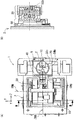
図1(A)は当該加工装置1の左側面図を示し、図1(B)は図1(A)におけるY軸移動手段30のAA断面図を示している。
また図2(A)は、当該加工装置1の平面図を示し、図2(B)は図2(A)におけるZ軸移動手段50とX軸移動手段60のBB断面図を示している。
また図3は、当該加工装置1の斜視図を示している。
図1〜図3に示す加工装置1は、直交する水平方向の軸であるX軸とZ軸に平行な上面と、X軸とZ軸との双方に直交する鉛直下向き方向の軸であるY軸に平行な側面を備えたベッド2を有している。
ベッド2の上面には、X軸テーブル60bをX軸方向に移動可能なX軸移動手段60が載置され、X軸テーブル60b上には、Z軸テーブル50bをZ軸方向に移動可能なZ軸移動手段50が載置されている。また、Z軸テーブル50b上には、Z軸方向に平行なC軸(ワーク回転軸WZ)回りにワークWを回転可能なC軸回転手段40が載置されている。
ベッド2の側面(C軸回転手段40の先端側の側面)にはY軸テーブル30bをY軸方向に移動可能なY軸移動手段30が取り付けられており、Y軸テーブル30bにはB軸テーブル20bをY軸方向に平行なB軸回りに旋回可能なB軸旋回手段20が載置されている。また、B軸テーブル20bには砥石回転軸TZ回りに回転砥石Tを回転可能な工具回転手段10が取り付けられている。また、回転砥石Tの先端がB軸と接触するように、且つB軸と砥石回転軸TZとが直交するように設定されている。
Conventionally, when processing a concave Fresnel lens-shaped member, for example, it is processed using the processing apparatus 1 shown in FIGS.
FIG. 1A is a left side view of the processing apparatus 1, and FIG. 1B is a cross-sectional view taken along line AA of the Y-
2A shows a plan view of the processing apparatus 1, and FIG. 2B shows a BB cross-sectional view of the Z-axis moving means 50 and the X-axis moving means 60 in FIG. 2A.
FIG. 3 shows a perspective view of the processing apparatus 1.
The machining apparatus 1 shown in FIGS. 1 to 3 includes a top surface parallel to the X axis and the Z axis, which are orthogonal horizontal axes, and a vertically downward axis that is orthogonal to both the X axis and the Z axis. It has a
On the upper surface of the
A Y-axis moving means 30 capable of moving the Y-axis table 30b in the Y-axis direction is attached to the side surface of the bed 2 (the side surface on the distal end side of the C-axis rotating means 40), and the B-axis table is attached to the Y-axis table 30b. B-axis turning means 20 capable of turning 20b around the B-axis parallel to the Y-axis direction is placed. Further, a tool rotating means 10 capable of rotating the rotating grindstone T around the grindstone rotating shaft TZ is attached to the B-axis table 20b. Further, the rotary grindstone T is set so that the tip of the rotary grindstone T is in contact with the B axis, and the B axis and the grindstone rotation axis TZ are orthogonal to each other.
次に、図4(C)に凹型フレネルレンズ形状部材(以下、「ワークW」と記載する)の断面の例を示す。図4(C)の例に示すワークWは、図4(A)に示す凹型レンズL1から、図4(B)に示すハッチング部分を取り除いた形状である。
例えば、図1〜図3に示す加工装置1を用いて、このワークWの凹型フレネルレンズ形状を加工する場合、まず凹型フレネルレンズ形状が粗研削されたワークWを、ワーク回転軸WZとC軸が一致するようにC軸回転手段40の先端に取り付ける。そして、Y軸移動手段30を制御してワーク回転軸WZ(C軸)と砥石回転軸TZのY軸方向の位置を一致させ、B軸旋回手段20を制御してワーク回転軸WZと砥石回転軸TZとが直交するように設定し、Y軸方向の位置とB軸の旋回角度を固定する(図4(D)参照)。この状態から、ワークWをワーク回転軸WZ回りに回転させ、回転砥石Tを砥石回転軸TZ回りに回転させる。
そして、凹型フレネルレンズの断面形状に沿うようにX軸移動手段60とZ軸移動手段50を制御して回転砥石TをXZ平面内で移動させて、ワークWの凹型フレネルレンズ形状を仕上げ加工する(図5(B)参照)。
Next, FIG. 4C shows an example of a cross section of a concave Fresnel lens-shaped member (hereinafter referred to as “work W”). The workpiece W illustrated in the example of FIG. 4C has a shape in which the hatched portion illustrated in FIG. 4B is removed from the concave lens L1 illustrated in FIG.
For example, when processing the concave Fresnel lens shape of the workpiece W using the processing apparatus 1 shown in FIGS. 1 to 3, the workpiece W having the concave Fresnel lens shape coarsely ground is first converted into a workpiece rotation axis WZ and a C axis. Are attached to the tip of the C-axis rotating means 40 so as to match. Then, the Y-axis moving means 30 is controlled to match the position of the workpiece rotation axis WZ (C-axis) and the grindstone rotation axis TZ in the Y-axis direction, and the B-
Then, the X-axis moving means 60 and the Z-axis moving means 50 are controlled so as to follow the cross-sectional shape of the concave Fresnel lens, and the rotary grindstone T is moved in the XZ plane to finish the concave Fresnel lens shape of the workpiece W. (See FIG. 5B).
ここで、特許文献1に記載された従来技術では、回転砥石TをワークWの外周部から中心(ワーク回転軸WZ)に向かう方向に移動させて(図5(B)参照)、ワークWの凹型フレネルレンズ形状を加工している。
特許文献1に記載された従来技術では、図4(D)の例に示すワークWと回転砥石Tの配置において、図5(B)に示すようにワークWの外周部から中心部に向かう方向へと、回転砥石TをXZ平面内で移動させて加工するため、図6(B)に示すように回転砥石Tの径が大きい側の端面Tfの側の縁部から磨耗が進行していく。この磨耗が進行した回転砥石TでワークWの凹型フレネルレンズ形状を、図5(B)に示すように加工した場合、図6(B)に示すように、加工後のワークWの理想形状に対して残存部Rが残り、幅Dの形状誤差が発生する。当該幅Dの形状誤差部に入射された光は所望する方向に屈折させることができないため、レンズの集光効率を低下させる要因の1つとなっている。
本発明は、このような点に鑑みて創案されたものであり、凹型フレネルレンズ形状を、より高精度に加工することが可能な、凹型フレネルレンズ形状部材の加工方法、及び当該加工方法を用いてより高精度に研削された凹型フレネルレンズ形状部材を提供することを課題とする。
In the prior art described in Patent Document 1, in the arrangement of the workpiece W and the rotating grindstone T shown in the example of FIG. 4D, the direction from the outer peripheral portion to the center portion of the workpiece W as shown in FIG. Since the rotary grindstone T is moved and processed in the XZ plane, wear proceeds from the edge on the end face Tf side of the large diameter of the rotary grindstone T as shown in FIG. . When the concave Fresnel lens shape of the workpiece W is processed as shown in FIG. 5B with the rotating grindstone T where the wear has progressed, the ideal shape of the workpiece W after processing is obtained as shown in FIG. 6B. On the other hand, the remaining portion R remains and a shape error of the width D occurs. Since the light incident on the shape error portion having the width D cannot be refracted in a desired direction, it is one of the factors that reduce the light collection efficiency of the lens.
The present invention was devised in view of such points, and uses a processing method of a concave Fresnel lens shape member capable of processing a concave Fresnel lens shape with higher accuracy, and the processing method. It is another object of the present invention to provide a concave Fresnel lens-shaped member ground with higher accuracy.
上記課題を解決するための手段として、本発明の第1発明は、請求項1に記載されたとおりの凹型フレネルレンズ形状部材の加工方法である。
請求項1に記載の凹型フレネルレンズ形状部材の加工方法は、砥石回転軸に対して所定角度で傾斜した傾斜面を有するとともに当該傾斜面の先端の縁部が鋭利に成形された円盤状の回転砥石を用いた凹型フレネルレンズ形状部材の加工方法において、工作物回転軸回りに工作物を回転させ、前記砥石回転軸が前記工作物回転軸と直交するように前記工作物に対して前記回転砥石を配置する。
そして、前記工作物に対して前記回転砥石を、前記傾斜面方向で且つ前記工作物の回転中心から外周部に向かう方向に相対的に移動させるとともに前記工作物に切込む方向に相対的に移動させて凹型フレネルレンズ形状を加工する、凹型フレネルレンズ形状部材の加工方法である。
As means for solving the above-mentioned problems, a first invention of the present invention is a processing method for a concave Fresnel lens shaped member as described in claim 1.
The method for processing a concave Fresnel lens-shaped member according to claim 1 is a disk-shaped rotation having an inclined surface inclined at a predetermined angle with respect to the grindstone rotation axis and having a sharp edge formed at the tip of the inclined surface. In a processing method of a concave Fresnel lens-shaped member using a grindstone, the workpiece is rotated about a workpiece rotation axis, and the grindstone is rotated with respect to the workpiece so that the grindstone rotation axis is orthogonal to the workpiece rotation axis. Place.
Then, the rotary grindstone is moved relative to the workpiece in the direction of the inclined surface and in the direction from the rotation center of the workpiece toward the outer periphery, and in the direction of cutting into the workpiece. It is a processing method of a concave Fresnel lens-shaped member that causes the concave Fresnel lens shape to be processed.
また、本発明の第2発明は、請求項2に記載されたとおりの凹型フレネルレンズ形状部材の加工方法である。
請求項2に記載の凹型フレネルレンズ形状部材の加工方法は、請求項1に記載の凹型フレネルレンズ形状部材の加工方法であって、前記円盤状の回転砥石の形状は、砥石回転軸に対して所定角度で傾斜した傾斜面を有する円錐の裾部形状であり、前記裾部形状において前記砥石回転軸に直交する端面における径が大きい側の端面は平面に成形されている。
そして、前記径が大きい側の端面を前記工作物回転軸と一致させた位置から、前記工作物に対して前記回転砥石を、前記工作物回転軸に平行な方向に相対的に移動させて加工を開始し、前記工作物に対して前記回転砥石を、前記工作物回転軸から外周部に向かう前記工作物回転軸に直交する方向に、且つ前記回転砥石の径が小さい側の端面の方向に相対的に移動させながら、前記工作物に対して前記回転砥石を前記工作物回転軸に平行な方向に相対的に移動させて凹型フレネルレンズ形状を加工する、凹型フレネルレンズ形状部材の加工方法である。
The second invention of the present invention is a processing method for a concave Fresnel lens shaped member as described in
The processing method of the concave Fresnel lens-shaped member according to
Then, the rotary grindstone is moved relative to the workpiece in a direction parallel to the workpiece rotation axis from a position where the end surface on the larger diameter side coincides with the workpiece rotation axis. And the rotating grindstone with respect to the workpiece in a direction perpendicular to the workpiece rotating shaft from the workpiece rotating shaft toward the outer periphery, and in the direction of the end surface on the side where the diameter of the rotating grindstone is small. A processing method for a concave Fresnel lens shape member, wherein the concave Fresnel lens shape is processed by moving the rotating grindstone relative to the workpiece in a direction parallel to the workpiece rotation axis while relatively moving the workpiece. is there.
また、本発明の第3発明は、請求項3に記載されたとおりの凹型フレネルレンズ形状部材の加工方法である。
請求項3に記載の凹型フレネルレンズ形状部材の加工方法は、請求項1または2に記載の凹型フレネルレンズ形状部材の加工方法であって、前記回転砥石のツルーイングにおいて、2回目以降のツルーイングでは、前記砥石回転軸に直交する前記端面のツルーイングを行わず、前記傾斜面のツルーイングのみを行い、ツルーイング後の前記回転砥石の位置の補正は、前記砥石回転軸に平行な方向の補正を行わず、前記砥石回転軸に直交する方向の補正のみを行う、凹型フレネルレンズ形状部材の加工方法である。
A third invention of the present invention is a processing method for a concave Fresnel lens shaped member as described in claim 3.
The processing method of the concave Fresnel lens-shaped member according to claim 3 is the processing method of the concave Fresnel lens-shaped member according to
また、本発明の第4発明は、請求項4に記載されたとおりの凹型フレネルレンズ形状部材である。
請求項4に記載の凹型フレネルレンズ形状部材は、請求項1〜3のいずれかに記載の凹型フレネルレンズ形状部材の加工方法を用いて凹型フレネルレンズ形状が加工されている。
The fourth invention of the present invention is a concave Fresnel lens shaped member as described in claim 4.
The concave Fresnel lens shape member according to claim 4 is processed into a concave Fresnel lens shape using the method for processing a concave Fresnel lens shape member according to any one of claims 1 to 3.
また、本発明の第5発明は、請求項5に記載されたとおりの凹型フレネルレンズ形状部材である。
請求項5に記載の凹型フレネルレンズ形状部材は、請求項4に記載の凹型フレネルレンズ形状部材であって、前記凹型フレネルレンズ形状部材は、凸型フレネルレンズを製造するための金型である。
The fifth invention of the present invention is a concave Fresnel lens shaped member as described in claim 5.
A concave Fresnel lens shaped member according to claim 5 is a concave Fresnel lens shaped member according to claim 4, wherein the concave Fresnel lens shaped member is a mold for producing a convex Fresnel lens.
請求項1に記載の凹型フレネルレンズ形状部材の加工方法を用いれば、ワークWの回転中心から外周部に向かう方向に凹型フレネルレンズ形状部材を加工していく(図5(A)参照)ので、回転砥石Tの傾斜面Tkの側から磨耗が進む(図6(A)参照)。従って、図6(B)の「理想形状」に示すような残存部Rが発生しないので、より高精度に凹型フレネルレンズ形状を加工することができる。 If the processing method of the concave Fresnel lens-shaped member according to claim 1 is used, the concave Fresnel lens-shaped member is processed in a direction from the rotation center of the workpiece W toward the outer peripheral portion (see FIG. 5A). Wear proceeds from the inclined surface Tk side of the rotating grindstone T (see FIG. 6A). Accordingly, since the remaining portion R as shown in the “ideal shape” in FIG. 6B does not occur, the concave Fresnel lens shape can be processed with higher accuracy.
また、請求項2に記載の凹型フレネルレンズ形状部材の加工方法によれば、請求項1と同様に、ワークWの回転中心から外周部に向かう方向に回転砥石を移動させながら回転砥石を工作物回転軸に平行な方向に移動させて凹型フレネルレンズ形状部材を加工していく(図5(A)参照)、従って、回転砥石Tの傾斜面Tkの側から磨耗が進む(図6(A)参照)が、回転砥石Tの端面Tfの側からの磨耗は進まない。そして、図6(B)の「理想形状」に示すような残存部Rが発生しないので、より高精度に凹型フレネルレンズ形状を加工することができる。
According to the processing method of the concave Fresnel lens-shaped member according to
また、請求項3に記載の凹型フレネルレンズ形状部材の加工方法によれば、回転砥石Tの磨耗は傾斜面Tkの側から進み、端面Tfの側からの磨耗は進まないので、ワークWを加工する回転砥石の最外周縁部(図6(A)のEM部)は、この端面Tf上にある。従って、端面Tfは、最初に砥石回転軸に直交する平面に成形しておけば、それ以降は成形する必要がない。なお、端面Tfを成形する必要はないが、傾斜面Tkは成形する必要があり、傾斜面Tkを成形した後は、回転砥石の径が小さくなっているので、砥石回転軸に直交する方向の位置補正をすれば、砥石回転軸に平行な方向の位置補正までは必要ない。
従って、回転砥石の磨耗に対して成形と補正の手間を少なくすることができ、補正の誤差をより小さくすることができる。
Further, according to the processing method of the concave Fresnel lens-shaped member according to claim 3, the wear of the rotating grindstone T proceeds from the inclined surface Tk side, and the wear from the end surface Tf side does not proceed. The outermost peripheral edge portion (EM portion in FIG. 6A) of the rotating grindstone is on this end face Tf. Therefore, if the end face Tf is first formed into a plane orthogonal to the grinding wheel rotation axis, it is not necessary to form the end face Tf thereafter. Although it is not necessary to form the end face Tf, the inclined face Tk needs to be formed. After the inclined face Tk is formed, the diameter of the rotating grindstone is small, so that the end face Tf is perpendicular to the grindstone rotation axis. If position correction is performed, position correction in a direction parallel to the grindstone rotation axis is not necessary.
Therefore, it is possible to reduce the time and effort of forming and correcting the wear of the rotating grindstone, and the error in correction can be further reduced.
また、請求項4に記載の凹型フレネルレンズ形状部材によれば、容易に、且つより高精度に凹型フレネルレンズ形状部材を加工することができる。 In addition, according to the concave Fresnel lens shaped member of the fourth aspect, the concave Fresnel lens shaped member can be processed easily and with higher accuracy.
また、請求項5に記載の凹型フレネルレンズ形状部材によれば、容易に、且つより高精度に凹型フレネルレンズ形状の金型を加工できるので、当該金型を用いてより高精度な凸型フレネルレンズを製造することができる。 Further, according to the concave Fresnel lens-shaped member according to claim 5, a concave Fresnel lens-shaped mold can be easily and more accurately processed, so that a higher-precision convex Fresnel can be obtained using the mold. A lens can be manufactured.
以下に本発明を実施するための最良の形態を図面を用いて説明する。
例えば、ガラス製のフレネルレンズを製造する場合、高温に熱したガラス材料を、超硬やセラミックス等の硬脆材料の金型でプレスして成型する。
この金型にフレネルレンズ形状を加工する場合、円盤状の砥石の先端を鋭利に成形した回転砥石を用いて研削加工する。
以下、凸型フレネルレンズを製造するための、凹型フレネルレンズ形状の金型の加工を例として説明する。
The best mode for carrying out the present invention will be described below with reference to the drawings.
For example, when a glass Fresnel lens is manufactured, a glass material heated to a high temperature is pressed and molded with a die of a hard and brittle material such as cemented carbide or ceramics.
When processing the Fresnel lens shape on this mold, grinding is performed using a rotating grindstone in which the tip of a disk-shaped grindstone is sharply formed.
Hereinafter, processing of a concave Fresnel lens-shaped mold for manufacturing a convex Fresnel lens will be described as an example.
●[加工装置1の構成(図1〜図3)]
図1〜図3は、本発明の凹型フレネルレンズ形状部材を加工する加工装置1の例を示している。
なお、当該加工装置1の全体構成については、すでに説明しているので、説明を省略する。
回転砥石Tは、図4(D)及び図5(A)に示すように、砥石回転軸TZに対して所定角度で傾斜した傾斜面Tkを有し、傾斜面Tkの先端の縁部Eが鋭利に成形されている。回転砥石Tの形状をより具体的に説明すると、円錐の頂点側を取り除いた裾部の形状であり、砥石回転軸TZに直交する径が大きい側の端面Tfを先端側にしており、径が小さい側の端面は工具回転手段10に接続されている。径が大きい側の端面Tfの縁部Eは鋭角であり、この縁部Eと傾斜面TkにてワークW(凹型フレネルレンズ形状部材)を加工する。
● [Configuration of processing device 1 (FIGS. 1 to 3)]
1 to 3 show an example of a processing apparatus 1 for processing a concave Fresnel lens shaped member of the present invention.
In addition, since the whole structure of the said processing apparatus 1 has already been demonstrated, description is abbreviate | omitted.
As shown in FIGS. 4D and 5A, the rotating grindstone T has an inclined surface Tk that is inclined at a predetermined angle with respect to the grindstone rotating axis TZ, and an edge E at the tip of the inclined surface Tk is formed. Sharply shaped. The shape of the rotating grindstone T will be described more specifically. The shape of the skirt is obtained by removing the apex side of the cone, and the end surface Tf on the side having a large diameter orthogonal to the grindstone rotating shaft TZ is the front end side. The end face on the small side is connected to the
●[凹型フレネルレンズ形状部材の加工方法(図5)]
次に図5を用いて、凹型フレネルレンズ形状部材の加工方法について説明する。ここで、図5(A)は本実施の形態における加工方法を説明する図であり、図5(B)は従来の加工方法を説明する図である。
すでに説明したように、ワークWの回転中心であるワーク回転軸WZ(工作物回転軸に相当し、C軸回転手段40に取り付けられた状態では、C軸と一致)と、回転砥石Tの回転中心である砥石回転軸TZと、が直交するように、ワークWと回転砥石Tとが配置されている(図4(D)、図5(A)参照)。そして、この図5(A)に示す配置において、ワークWまたは回転砥石Tの少なくとも一方をXZ平面内で移動させて、粗研削で加工されたワークWの凹型フレネルレンズ形状を、仕上げ加工する。
● [Processing method for concave Fresnel lens-shaped members (Fig. 5)]
Next, a method for processing a concave Fresnel lens-shaped member will be described with reference to FIG. Here, FIG. 5A is a diagram for explaining a processing method in the present embodiment, and FIG. 5B is a diagram for explaining a conventional processing method.
As already described, the workpiece rotation axis WZ (corresponding to the workpiece rotation axis and coincides with the C axis when attached to the C axis rotation means 40), which is the rotation center of the workpiece W, and the rotation of the rotating grindstone T The workpiece W and the rotating grindstone T are arranged so that the grindstone rotation axis TZ as the center is orthogonal (see FIGS. 4D and 5A). Then, in the arrangement shown in FIG. 5A, at least one of the workpiece W or the rotating grindstone T is moved in the XZ plane, and the concave Fresnel lens shape of the workpiece W processed by rough grinding is finished.
まず、制御装置(数値制御装置等であり、図示省略)を用いて、Y軸移動手段30とB軸旋回手段20を制御して、ワーク回転軸WZと砥石回転軸TZとが直交するようにワークWと回転砥石Tとを位置決めする。
次に、制御装置からC軸回転手段40を制御してワークWをワーク回転軸WZ回りに回転させ、工具回転手段10を制御して回転砥石Tを砥石回転軸TZ回りに回転させる。
そして、制御装置からX軸移動手段60を制御して、図5(A)に示すように、回転砥石Tの径が大きい側の端面Tfとワーク回転軸WZとが接する(一致する)ようにワークWを位置決めする。
First, by using a control device (a numerical control device or the like, not shown), the Y-
Next, the control device controls the C-axis rotation means 40 to rotate the workpiece W around the workpiece rotation axis WZ, and controls the tool rotation means 10 to rotate the rotating grindstone T around the grindstone rotation axis TZ.
Then, by controlling the X-axis moving means 60 from the control device, as shown in FIG. 5 (A), the end surface Tf on the side with the larger diameter of the rotating grindstone T and the workpiece rotation axis WZ are in contact (match). Position the workpiece W.
そして、制御装置からZ軸移動手段50を制御して、回転砥石Tの縁部Eに近接する方向にワークWを移動させて加工を開始し、X軸移動手段60を用いてワークWを、ワーク回転軸WZに直交する方向であるX軸方向に、且つ回転砥石Tの径が小さい側の端面の方向に移動させながら、Z軸移動手段50を用いてワークWをワーク回転軸WZに平行な方向であるZ軸方向に移動させる。この移動により、回転砥石Tの縁部EとワークWとの接点の軌跡が、図5(A)に示すワークWのフレネルレンズ形状の輪郭の軌跡となるようにして加工し、凹型フレネルレンズ形状を加工する。
このように、回転砥石TをワークWの回転中心から外周部に向かう方向に相対的に移動させるとともにワークWに切込む方向に相対的に移動させて凹型フレネルレンズ形状を加工する。
Then, the control device controls the Z-
In this way, the rotating grindstone T is relatively moved in the direction from the rotation center of the workpiece W toward the outer periphery, and is also relatively moved in the direction of cutting into the workpiece W to process the concave Fresnel lens shape.
特開2000−237942に記載されている従来の加工方法は、図5(B)に示すように、回転砥石TがワークWの外周部から回転中心に向かう方向に相対的に移動させながら研削しており、本実施の形態とはまったく逆の方向に回転砥石Tを移動させて加工している。 As shown in FIG. 5 (B), the conventional machining method described in Japanese Patent Laid-Open No. 2000-237942 performs grinding while moving the rotating grindstone T relatively in the direction from the outer periphery of the workpiece W toward the rotation center. The rotary grindstone T is moved and processed in the direction completely opposite to the present embodiment.
●[回転砥石Tの磨耗(図6)]
次に図6を用いて、回転砥石Tの磨耗について説明する。ここで、図6(A)は本実施の形態における加工方法による回転砥石Tの磨耗を説明する図であり、図6(B)は従来の加工方法による回転砥石Tの磨耗を説明する図である。
硬脆材料の金型を回転砥石Tで加工するので、回転砥石Tは当然磨耗する。更に、当然のことながら、回転砥石TにおけるワークWに切込む切込面が、回転砥石Tの切込方向(ワークWに対して回転砥石Tの相対的な切込方向)と反対方向に磨耗が進行していく。
● [Abrasion of rotating wheel T (Fig. 6)]
Next, the wear of the rotating grindstone T will be described with reference to FIG. Here, FIG. 6 (A) is a diagram for explaining the wear of the rotating grindstone T by the processing method in the present embodiment, and FIG. 6 (B) is a diagram for explaining the wear of the rotating grindstone T by the conventional processing method. is there.
Since the mold of the hard and brittle material is processed by the rotating grindstone T, the rotating grindstone T naturally wears. Further, as a matter of course, the cutting surface to be cut into the workpiece W in the rotating grindstone T is worn in the direction opposite to the cutting direction of the rotating grindstone T (the relative cutting direction of the rotating grindstone T with respect to the workpiece W). Will progress.
図6(B)に示す従来の加工方法の場合、回転砥石Tの切込面は端面Tfであり、この端面Tfが切込方向と反対側に磨耗していく。この場合、図6(B)に示すように、磨耗後の回転砥石Tにおいて、最外周縁部EMは端面Tf上には存在せず、傾斜面Tkの側に存在する。この磨耗した回転砥石Tで加工した場合、理想形状に対して残存部Rが発生する。この残存部Rは、フレネルレンズに入射される光を、所望する方向に屈折できないので、集光効率の低下の要因となる。 In the case of the conventional processing method shown in FIG. 6B, the cutting surface of the rotating grindstone T is an end surface Tf, and this end surface Tf is worn away on the side opposite to the cutting direction. In this case, as shown in FIG. 6B, in the rotating grindstone T after wear, the outermost peripheral edge portion EM does not exist on the end face Tf but exists on the inclined face Tk side. When processing with the worn rotating grindstone T, a remaining portion R is generated with respect to the ideal shape. The remaining portion R becomes a factor of a reduction in light collection efficiency because light incident on the Fresnel lens cannot be refracted in a desired direction.
これに対して、本実施の形態にて説明した加工方法の場合、図6(A)に示すように、回転砥石Tの切込面は傾斜面Tkであり、この傾斜面Tkが切込方向と反対側に磨耗していく。この場合、図6(A)に示すように、磨耗後の回転砥石Tにおいて、最外周縁部EMは端面Tf上にあり、図6(B)に示す残存部Rが発生しない。 On the other hand, in the case of the processing method described in the present embodiment, as shown in FIG. 6A, the cutting surface of the rotating grindstone T is an inclined surface Tk, and this inclined surface Tk is the cutting direction. And wear on the opposite side. In this case, as shown in FIG. 6A, in the rotating grindstone T after wear, the outermost peripheral edge EM is on the end face Tf, and the remaining portion R shown in FIG. 6B does not occur.
●[回転砥石Tの成形方法と、成形後の位置補正方法(図7、図8)]
回転砥石Tを成形する場合、ワークWの代わりに略円柱形状のツルア70をC軸回転手段40に取り付け、ツルア70をC軸回りに回転させる。
例えば、回転砥石Tの端面Tfを成形する場合、C軸と砥石回転軸TZのY軸方向の位置を一致させた状態で、ツルア70におけるC軸に直交する端面70fに、回転砥石Tの端面Tfを接触させて成形する(図7(A)参照)。
また更に、回転砥石Tの傾斜面Tkを成形する場合、B軸旋回手段20を用いてツルア70における円筒面70s(外周面)に、回転砥石Tの傾斜面Tkを接触させて成形する(図7(B)参照)。この場合、B軸旋回手段20の旋回角度を調整することで、砥石回転軸TZに対する傾斜面Tkの傾斜角度を任意の角度にすることができる。
回転砥石Tを初めて使用する場合は、上記の方法にて、端面Tfと傾斜面Tkとを成形する必要があるが、いくつかのワークWを加工して磨耗が進行した回転砥石Tを成形する場合(2回目以降のツルーイングでは)、本実施の形態の場合、回転砥石Tの端面Tfを成形する必要がなく、傾斜面Tkを成形するだけでよい。従来の加工方法による磨耗の場合は、端面Tfと傾斜面Tkの双方を研削する必要がある。
● [Formation method of rotating grindstone T and position correction method after molding (FIGS. 7 and 8)]
When forming the rotating grindstone T, instead of the workpiece W, a substantially
For example, when the end surface Tf of the rotating grindstone T is formed, the end surface of the rotating grindstone T is placed on the end surface 70f perpendicular to the C axis in the truer 70 in a state where the positions of the C axis and the grindstone rotating shaft TZ are matched. Molding is performed by bringing Tf into contact (see FIG. 7A).
Furthermore, when the inclined surface Tk of the rotating grindstone T is formed, the inclined surface Tk of the rotating grindstone T is formed in contact with the
When the rotary grindstone T is used for the first time, it is necessary to mold the end face Tf and the inclined surface Tk by the above method. However, several workpieces W are processed to mold the rotary grindstone T in which wear has progressed. In this case (in the second and subsequent truing), in the case of the present embodiment, it is not necessary to form the end face Tf of the rotating grindstone T, and it is only necessary to form the inclined face Tk. In the case of wear by a conventional processing method, it is necessary to grind both the end face Tf and the inclined face Tk.
本実施の形態の場合、2回目以降の成形(ツルーイング)では、成形後の端面Tfの位置が変化しない(径のみが変化する)ので、回転砥石Tの径方向の位置補正を行うだけでよく、回転砥石Tの位置補正が簡素化される。つまり、砥石回転軸TZに直交する方向の位置補正は必要であるが、砥石回転軸TZに平行な方向の位置補正は不要である。
これにより、成形と位置補正の手間が少なく、サイクルタイムを短縮化することができ、補正の誤差もより小さくすることができる。
In the case of the present embodiment, in the second and subsequent molding (truing), the position of the end face Tf after molding does not change (only the diameter changes), so it is only necessary to correct the radial position of the rotating grindstone T. The position correction of the rotating grindstone T is simplified. That is, position correction in the direction orthogonal to the grindstone rotation axis TZ is necessary, but position correction in the direction parallel to the grindstone rotation axis TZ is not necessary.
As a result, it is possible to reduce the time for molding and position correction, to shorten the cycle time, and to further reduce the correction error.
なお、砥石回転軸TZに平行な方向における回転砥石Tの位置の補正方法の例を図8(A)及び(B)に示す。
まず、ワークWの代わりに略円柱(円盤)形状のカーボンワークCWをC軸回転手段40に取り付け、カーボンワークCWをC軸回りに回転させる。
そして、砥石回転軸TZがC軸に直交するように回転砥石Tを位置決めし、回転砥石Tの端面TfをC軸と一致させて回転砥石TをカーボンワークCWの方向に切込む。
このとき、回転砥石Tの端面Tfにおける砥石回転軸TZに平行な側の位置がずれていた場合、図8(B)に示すように、カーボンワークCWの端面Sfに、C軸を中心とした半径ERの接触痕Kが残る。この接触痕Kの半径ERを求め、半径ER分の距離を補正すればよい。この補正は、端面Tfを成形した後にのみ実行すればよい。
なお、回転砥石Tの径方向の補正量は、上記の端面Tfの位置ほどシビアに補正する必要がなく、ツルーイング時に径を認識するようにすればよい。
An example of a method for correcting the position of the rotating grindstone T in the direction parallel to the grindstone rotation axis TZ is shown in FIGS.
First, instead of the workpiece W, a substantially cylindrical (disk) -shaped carbon workpiece CW is attached to the C-
Then, the rotating grindstone T is positioned so that the grindstone rotating shaft TZ is orthogonal to the C axis, the end surface Tf of the rotating grindstone T is aligned with the C axis, and the rotating grindstone T is cut in the direction of the carbon workpiece CW.
At this time, when the position of the end surface Tf of the rotating grindstone T on the side parallel to the grindstone rotation axis TZ is shifted, as shown in FIG. 8B, the end surface Sf of the carbon workpiece CW is centered on the C axis. A contact mark K having a radius ER remains. The radius ER of the contact mark K may be obtained and the distance corresponding to the radius ER may be corrected. This correction only needs to be performed after the end face Tf is formed.
Note that the correction amount in the radial direction of the rotating grindstone T does not need to be corrected as severely as the position of the end face Tf, and the diameter may be recognized during truing.
以上、本実施の形態の説明では、回転砥石Tに対してワークWをX軸方向に移動させたが、ワークWに対して回転砥石TをX軸方向に移動させる構成にすることもできる。従って、ワークWは回転砥石Tに対して相対的にX軸方向に移動するものである。
同様に、Z軸方向については、回転砥石Tに対してワークWをZ軸方向に移動させたが、ワークWに対して回転砥石TをZ軸方向に移動させる構成にすることもできる。従って、ワークWは回転砥石Tに対して相対的にZ軸方向に移動するものである。
As described above, in the description of the present embodiment, the workpiece W is moved in the X-axis direction with respect to the rotary grindstone T. However, the rotary grindstone T can be moved in the X-axis direction with respect to the workpiece W. Accordingly, the workpiece W moves in the X-axis direction relative to the rotating grindstone T.
Similarly, in the Z-axis direction, the workpiece W is moved in the Z-axis direction with respect to the rotating grindstone T. However, the rotating grindstone T may be moved in the Z-axis direction with respect to the workpiece W. Accordingly, the workpiece W moves in the Z-axis direction relative to the rotating grindstone T.
本発明の凹型フレネルレンズ形状部材の加工方法は、本実施の形態で説明した方法に限定されず、本発明の要旨を変更しない範囲で種々の変更、追加、削除が可能である。
また、本実施の形態の説明では、粗研削された凹型フレネルレンズ形状部材を仕上げ加工する例で説明したが、円柱状のワークの端面(平面)から凹型フレネルレンズ形状部材を削り出すこともできる。
The processing method of the concave Fresnel lens-shaped member of the present invention is not limited to the method described in the present embodiment, and various modifications, additions and deletions can be made without changing the gist of the present invention.
In the description of the present embodiment, an example in which a rough-ground concave Fresnel lens-shaped member is finished has been described. However, a concave Fresnel lens-shaped member can be cut out from an end surface (plane) of a cylindrical workpiece. .
1 加工装置
2 ベッド
10 工具回転手段
20 B軸旋回手段
30 Y軸移動手段
30b Y軸テーブル
40 C軸回転手段
50 Z軸移動手段
50b Z軸テーブル
60 X軸移動手段
60b X軸テーブル
70 ツルア
T 回転砥石
Tk 傾斜面
Tf 端面(径が大きい側の端面)
TZ 砥石回転軸
E 縁部
EM 最外周縁部
W ワーク(凹型フレネルレンズ形状部材)
WZ ワーク回転軸(工作物回転軸)
DESCRIPTION OF SYMBOLS 1
TZ Grinding wheel rotating shaft E Edge EM Outermost peripheral edge W Workpiece (concave Fresnel lens shaped member)
WZ Workpiece rotation axis (workpiece rotation axis)
Claims (5)
工作物回転軸回りに工作物を回転させ、
前記砥石回転軸が前記工作物回転軸と直交するように前記工作物に対して前記回転砥石を配置し、
前記工作物に対して前記回転砥石を、前記傾斜面方向で且つ前記工作物の回転中心から外周部に向かう方向に相対的に移動させるとともに前記工作物に切込む方向に相対的に移動させて凹型フレネルレンズ形状を加工する、
凹型フレネルレンズ形状部材の加工方法。 In the processing method of the concave Fresnel lens-shaped member using a disk-shaped rotating grindstone having an inclined surface inclined at a predetermined angle with respect to the grindstone rotation axis and the edge of the tip of the inclined surface is sharply formed,
Rotate the workpiece around the workpiece rotation axis,
Arranging the rotating grindstone with respect to the workpiece such that the grindstone rotating axis is orthogonal to the workpiece rotating axis;
The rotary grindstone is moved relative to the workpiece in the direction of the inclined surface and in the direction from the rotation center of the workpiece to the outer peripheral portion and in the direction of cutting into the workpiece. Processing concave Fresnel lens shape,
Processing method for concave Fresnel lens shaped member.
前記円盤状の回転砥石の形状は、砥石回転軸に対して所定角度で傾斜した傾斜面を有する円錐の裾部形状であり、前記裾部形状において前記砥石回転軸に直交する端面における径が大きい側の端面は平面に成形されており、
前記径が大きい側の端面を前記工作物回転軸と一致させた位置から、前記工作物に対して前記回転砥石を、前記工作物回転軸に平行な方向に相対的に移動させて加工を開始し、
前記工作物に対して前記回転砥石を、前記工作物回転軸から外周部に向かう前記工作物回転軸に直交する方向に、且つ前記回転砥石の径が小さい側の端面の方向に相対的に移動させながら、前記工作物に対して前記回転砥石を前記工作物回転軸に平行な方向に相対的に移動させて凹型フレネルレンズ形状を加工する、
凹型フレネルレンズ形状部材の加工方法。 A processing method for a concave Fresnel lens-shaped member according to claim 1,
The shape of the disk-shaped rotating grindstone is a conical skirt shape having an inclined surface inclined at a predetermined angle with respect to the grindstone rotation axis, and the diameter of the end surface perpendicular to the grindstone rotation axis in the skirt shape is large. The end face on the side is molded into a flat surface,
Starting from the position where the end surface on the larger diameter side coincides with the workpiece rotation axis, the rotary grindstone is moved relative to the workpiece in a direction parallel to the workpiece rotation axis to start machining. And
The rotary grindstone is moved relative to the workpiece in a direction perpendicular to the workpiece rotation axis from the workpiece rotation axis toward the outer periphery, and in the direction of the end surface on the side where the diameter of the rotation grindstone is small. While moving the rotating grindstone relative to the workpiece in a direction parallel to the workpiece rotation axis to process a concave Fresnel lens shape,
Processing method for concave Fresnel lens shaped member.
前記回転砥石のツルーイングにおいて、2回目以降のツルーイングでは、前記砥石回転軸に直交する前記端面のツルーイングを行わず、前記傾斜面のツルーイングのみを行い、
ツルーイング後の前記回転砥石の位置の補正は、前記砥石回転軸に平行な方向の補正を行わず、前記砥石回転軸に直交する方向の補正のみを行う、
凹型フレネルレンズ形状部材の加工方法。 A method for processing a concave Fresnel lens-shaped member according to claim 1 or 2,
In the truing of the rotating grindstone, in the second and subsequent truing, the truing of the end surface orthogonal to the grindstone rotating axis is not performed, and only the truing of the inclined surface is performed,
The correction of the position of the rotating grindstone after truing does not correct in the direction parallel to the grindstone rotation axis, but only corrects the direction orthogonal to the grindstone rotation axis.
Processing method for concave Fresnel lens shaped member.
凹型フレネルレンズ形状部材。 The concave Fresnel lens shape was processed using the processing method of the concave Fresnel lens shape member according to claim 1,
Concave Fresnel lens shaped member.
前記凹型フレネルレンズ形状部材は、凸型フレネルレンズを製造するための金型である、
凹型フレネルレンズ形状部材。 The concave Fresnel lens-shaped member according to claim 4,
The concave Fresnel lens-shaped member is a mold for producing a convex Fresnel lens.
Concave Fresnel lens shaped member.
Priority Applications (1)
| Application Number | Priority Date | Filing Date | Title |
|---|---|---|---|
| JP2008026416A JP5181703B2 (en) | 2008-02-06 | 2008-02-06 | Processing method of concave Fresnel lens shaped member and concave Fresnel lens shaped member |
Applications Claiming Priority (1)
| Application Number | Priority Date | Filing Date | Title |
|---|---|---|---|
| JP2008026416A JP5181703B2 (en) | 2008-02-06 | 2008-02-06 | Processing method of concave Fresnel lens shaped member and concave Fresnel lens shaped member |
Publications (3)
| Publication Number | Publication Date |
|---|---|
| JP2009184066A JP2009184066A (en) | 2009-08-20 |
| JP2009184066A5 JP2009184066A5 (en) | 2011-10-06 |
| JP5181703B2 true JP5181703B2 (en) | 2013-04-10 |
Family
ID=41067858
Family Applications (1)
| Application Number | Title | Priority Date | Filing Date |
|---|---|---|---|
| JP2008026416A Expired - Fee Related JP5181703B2 (en) | 2008-02-06 | 2008-02-06 | Processing method of concave Fresnel lens shaped member and concave Fresnel lens shaped member |
Country Status (1)
| Country | Link |
|---|---|
| JP (1) | JP5181703B2 (en) |
Families Citing this family (8)
| Publication number | Priority date | Publication date | Assignee | Title |
|---|---|---|---|---|
| FR2964753B1 (en) | 2010-09-14 | 2012-09-28 | Commissariat Energie Atomique | METHOD FOR MANUFACTURING A SEGMENTED OPTICAL STRUCTURE |
| CN102126173A (en) * | 2010-12-15 | 2011-07-20 | 湖南大学 | Fresnel glass lens mould processing method |
| CN102537832B (en) * | 2010-12-29 | 2014-05-07 | 海洋王照明科技股份有限公司 | Fresnel lens and lamp with same |
| CN106181688A (en) * | 2016-07-14 | 2016-12-07 | 常州湖南大学机械装备研究院 | A kind of method for grinding of Fresnel Lenses mould |
| CN107037513A (en) * | 2017-02-23 | 2017-08-11 | 上海斐讯数据通信技术有限公司 | Fresnel Lenses and electronic installation and optical module |
| JP6953182B2 (en) * | 2017-05-23 | 2021-10-27 | 東京コスモス電機株式会社 | Heat generator |
| JP6953179B2 (en) * | 2017-05-23 | 2021-10-27 | 東京コスモス電機株式会社 | Heat generator |
| CN115319625A (en) * | 2022-08-11 | 2022-11-11 | 浙江百康光学股份有限公司 | Workpiece polishing process |
Family Cites Families (3)
| Publication number | Priority date | Publication date | Assignee | Title |
|---|---|---|---|---|
| JPH08160211A (en) * | 1994-12-09 | 1996-06-21 | Olympus Optical Co Ltd | Production of metal mold and production of optical element using the same |
| JP3762248B2 (en) * | 2001-04-24 | 2006-04-05 | キヤノン株式会社 | Die processing method for diffractive optical element |
| JP2008142799A (en) * | 2006-12-06 | 2008-06-26 | Olympus Corp | Working method for diffraction groove |
-
2008
- 2008-02-06 JP JP2008026416A patent/JP5181703B2/en not_active Expired - Fee Related
Also Published As
| Publication number | Publication date |
|---|---|
| JP2009184066A (en) | 2009-08-20 |
Similar Documents
| Publication | Publication Date | Title |
|---|---|---|
| JP5181703B2 (en) | Processing method of concave Fresnel lens shaped member and concave Fresnel lens shaped member | |
| JP2009184066A5 (en) | ||
| JP5213442B2 (en) | Raster cutting technology for ophthalmic lenses | |
| JP5416956B2 (en) | Truing tool for grinding wheel and manufacturing method thereof, truing device using the same, manufacturing method of grinding wheel, and wafer edge grinding apparatus | |
| JP6487435B2 (en) | Method for machining a tooth edge and a machining station designed for this purpose | |
| JP5846082B2 (en) | Grinding method for skiving cutter | |
| JP4576255B2 (en) | Tool whetstone shape creation method | |
| JP2006289566A (en) | Grinding processing method and grinding processing device of forming die of micro lens array | |
| CN107695883B (en) | Shaping and trimming device and shaping and trimming method | |
| US20170182613A1 (en) | Grinding machine and method for machining a workpiece | |
| JP2005131724A (en) | Aspheric surface processing method, aspheric surface forming method and aspheric surface processing apparatus | |
| CN109202692A (en) | Grinding device and grinding operation method | |
| JP7158702B2 (en) | chamfering grinder | |
| JP7016568B1 (en) | Fresnel lens mold manufacturing method, processing equipment and cutting tools | |
| JP5538754B2 (en) | Manufacturing method of adjusting wheel for centerless grinding, adjusting wheel, manufacturing method of tapered roller | |
| JP7226818B2 (en) | Dressing tool truing method and dressing tool truing program | |
| JP5017544B2 (en) | Spectacle lens precursor, spectacle lens and method of processing the same | |
| JP2008142799A (en) | Working method for diffraction groove | |
| JP2017124460A (en) | Method and apparatus for continuously processing non-spherical shape of workpiece by cup shaped grind stone | |
| JP2002321146A (en) | Method for processing metal mold for diffraction optical element | |
| WO2006132126A1 (en) | Method of producing optical element, and optical element | |
| JP2006055961A (en) | Method and apparatus for machining axially symmetric aspheric surface by surface grinding machine | |
| JPH05162005A (en) | Turning machine with cutting tool forming function | |
| JP3910935B2 (en) | Work grinding method and grinding apparatus | |
| JP2006326833A (en) | Method of machining aspheric surface |
Legal Events
| Date | Code | Title | Description |
|---|---|---|---|
| A621 | Written request for application examination |
Free format text: JAPANESE INTERMEDIATE CODE: A621 Effective date: 20110120 |
|
| A521 | Written amendment |
Free format text: JAPANESE INTERMEDIATE CODE: A523 Effective date: 20110809 |
|
| A521 | Written amendment |
Free format text: JAPANESE INTERMEDIATE CODE: A523 Effective date: 20110824 |
|
| TRDD | Decision of grant or rejection written | ||
| A977 | Report on retrieval |
Free format text: JAPANESE INTERMEDIATE CODE: A971007 Effective date: 20121213 |
|
| A01 | Written decision to grant a patent or to grant a registration (utility model) |
Free format text: JAPANESE INTERMEDIATE CODE: A01 Effective date: 20121218 |
|
| A61 | First payment of annual fees (during grant procedure) |
Free format text: JAPANESE INTERMEDIATE CODE: A61 Effective date: 20121231 |
|
| R150 | Certificate of patent (=grant) or registration of utility model |
Free format text: JAPANESE INTERMEDIATE CODE: R150 |
|
| FPAY | Renewal fee payment (event date is renewal date of database) |
Free format text: PAYMENT UNTIL: 20160125 Year of fee payment: 3 |
|
| LAPS | Cancellation because of no payment of annual fees |