JP5179772B2 - Press machine - Google Patents
Press machine Download PDFInfo
- Publication number
- JP5179772B2 JP5179772B2 JP2007104572A JP2007104572A JP5179772B2 JP 5179772 B2 JP5179772 B2 JP 5179772B2 JP 2007104572 A JP2007104572 A JP 2007104572A JP 2007104572 A JP2007104572 A JP 2007104572A JP 5179772 B2 JP5179772 B2 JP 5179772B2
- Authority
- JP
- Japan
- Prior art keywords
- slider
- base
- screw shaft
- fixed
- screw
- Prior art date
- Legal status (The legal status is an assumption and is not a legal conclusion. Google has not performed a legal analysis and makes no representation as to the accuracy of the status listed.)
- Active
Links
- 238000003825 pressing Methods 0.000 claims description 2
- 230000000149 penetrating effect Effects 0.000 claims 2
- 230000002093 peripheral effect Effects 0.000 description 4
- 230000008859 change Effects 0.000 description 2
- 238000000034 method Methods 0.000 description 2
- 230000008569 process Effects 0.000 description 2
- 101100233916 Saccharomyces cerevisiae (strain ATCC 204508 / S288c) KAR5 gene Proteins 0.000 description 1
- 230000008878 coupling Effects 0.000 description 1
- 238000010168 coupling process Methods 0.000 description 1
- 238000005859 coupling reaction Methods 0.000 description 1
- 238000010586 diagram Methods 0.000 description 1
- 238000004519 manufacturing process Methods 0.000 description 1
- 230000010355 oscillation Effects 0.000 description 1
- 230000004044 response Effects 0.000 description 1
Images


Description
本発明は、1つまたは複数個の駆動源、例えば1つまたは複数個の電動機によって駆動されるスライダを有し、スライダの移動によって被加工体をプレス加工するプレス装置に関する。 The present invention relates to a press apparatus that includes a slider driven by one or a plurality of driving sources, for example, one or a plurality of electric motors, and presses a workpiece by moving the slider.
近年、電動機を駆動源とするプレス装置が実用の域に達し、個々の電動機による例えばスライダの四角近傍に作用する力によって基台に対してスライダが移動されて、被加工体をプレス加工するに当たって、前記電動機の制御によって当該スライダを、被加工体による偏心荷重にも拘らず、前記基台に対していわば完全に平行状態に保ちつつ、被加工体をプレス加工されるようにされることが行われている(特許文献1,特許文献2参照)。
実用の域に達している現状の前記電動機駆動のプレス装置においては、スライダを基台に対して上下動させるに当たって、電動機によって回転されるねじ軸を備え、当該ねじ軸の回転によって、スライダに備えられたナットを介して当該スライダが上下動せしめられるよう構成されている。 In the present motor-driven press device that has reached the practical range, the slider is provided with a screw shaft that is rotated by the motor when the slider is moved up and down with respect to the base. The slider is configured to be moved up and down through the nut.
また、この種の電動機駆動によるプレス装置において、被加工体が現にプレス加工されつつある状態の下での、前記スライダの比較的小さい移動距離の間に限って、前記ねじ軸の回転をロックせしめた上でスライダに存在するナットの側を回転させることが行われることがある。 Further, in this type of electric motor-driven press device, the rotation of the screw shaft is locked only during a relatively small movement distance of the slider under a state where the workpiece is actually being pressed. In addition, the nut side existing in the slider may be rotated.
しかし、いずれにしても、基台に対してスライダが位置移動する基本的な構成は、電動機によってねじ軸が回転せしめられ、当該ねじ軸の回転に伴ってスライダが上下動する構成となっている。 However, in any case, the basic configuration in which the slider moves relative to the base is a configuration in which the screw shaft is rotated by an electric motor and the slider moves up and down as the screw shaft rotates. .
プレス装置の全体の価格を低減するために、基台と当該基台に対して門型の太い支柱で支えられた構造の上部水平部分支持板をもつ従来の構成に代えて、門型構造を省略ないしは可能な限り簡単化しようとすることがあるが、このような場合に、ねじ軸の回転ブレが生じる。 In order to reduce the overall price of the press device, instead of the conventional configuration with a base and an upper horizontal partial support plate with a structure supported by a thick gate-shaped support to the base, a portal structure is used. Omitting or trying to simplify as much as possible may occur, but in such a case, rotational blurring of the screw shaft occurs.
即ち、この種の電動機駆動によるプレス装置において、スライダが上下動する間においてもスライダの水平度をより厳密に制御しようと努力を続けている状況の下でねじ軸の回転ブレが生じることが判った。特に前記ねじ軸として比較的細くて長いねじ軸を用いられるような場合に、当該ねじ軸が回転せしめられる際に当該ねじ軸が当該ねじ軸の軸心に対してブレが生じ易くなり、スライダを厳密に水平に保ちつつ上下動させる上で困難となることが判った。 In other words, in this type of electric motor-driven press device, it can be seen that even when the slider moves up and down, rotation blurring of the screw shaft occurs under a situation where efforts are made to more precisely control the level of the slider. It was. In particular, when a relatively thin and long screw shaft is used as the screw shaft, when the screw shaft is rotated, the screw shaft is likely to be shaken with respect to the axis of the screw shaft, and the slider It was found that it would be difficult to move up and down while keeping strictly horizontal.
またスライダが上下動する間に、スライダが基台と平行する方向に揺動することを防止するために前記支柱をガイド柱として利用し、スライダが当該支柱に支えられて摺動されつつ上下動するようにした従来の構成を変更しようとする場合に、ねじ軸の回転ブレがスライダの水平方向のブレの原因となることが判明した。 In order to prevent the slider from swinging in a direction parallel to the base while the slider is moving up and down, the support column is used as a guide column, and the slider is moved up and down while being supported by the support column. It has been found that the rotational shake of the screw shaft causes the horizontal shake of the slider when trying to change the conventional configuration.
本発明は、上記の解題を解決するために、前記ねじ軸を非回転状態に、基台に対してあるいは基台に固定的に存在する固定部(又は支持体)に対してあるいはスライダに対して固定的に取り付けるようにしてねじ軸が回転しないようにし、ねじ軸の回転に伴う回転ブレを完全に防止するようにしている。即ち、スライダに設けられているあるいは基台に設けられているあるいは前記固定部に設けられているナットの側を回転駆動せしめてスライダを上下動するようにしている。そしてその上で、ねじ軸としていわば比較的断面積の大きいものを用いるか、ねじ軸の個数を多くするようにして、ねじ軸全体でもってスライダが基台に対して平行な方向に揺動することを抑止するようにしている。換言すると、従来のプレス装置において介在していた所の、スライダの前記揺動を抑止していた太いガイド柱を省略することを可能にしている。 In order to solve the above problem, the present invention provides the screw shaft in a non-rotating state, with respect to a base, to a fixed portion (or support) that is fixed to the base, or to a slider. Thus, the screw shaft is prevented from rotating by being fixedly attached so as to completely prevent the rotation blur caused by the rotation of the screw shaft. That is, the slider is moved up and down by rotationally driving a nut provided on the slider, on the base, or on the fixed portion. On that basis, a screw shaft with a relatively large cross-sectional area is used, or the number of screw shafts is increased so that the slider swings in a direction parallel to the base with the entire screw shaft. I try to deter that. In other words, it is possible to omit the thick guide column that has been interposed in the conventional press apparatus and has suppressed the swing of the slider.
前述のように、前記ガイド柱を省略しても、ねじ軸自体を例えば太くして、ねじ軸が基台に対してあるいは基台に対して固定されている固定部に対してあるいはスライダに対して非回転状態に固定されているために、ねじ軸が回転駆動される従来の場合にくらべて、ねじ軸が回転ブレを生じることがない。したがって、スライダが上下動する間におけるスライダの水平度を厳密に保つようにすることが可能となる。 As described above, even if the guide pillar is omitted, the screw shaft itself is made thicker, for example, and the screw shaft is fixed to the base or the fixed portion fixed to the base or to the slider. Since the screw shaft is fixed in a non-rotating state, the screw shaft does not cause rotational vibration compared to the conventional case where the screw shaft is rotationally driven. Therefore, it becomes possible to keep the level of the slider strictly while the slider moves up and down.
図5および図6は発明展開段階で考慮された構成についての説明図である。当該図5は正面図、図6は上面図である。図5および図6は、前記特許文献1,2に開示されているプレス装置において、構造を簡略化するために、門型構造を省略することを考慮した構成に対応している。
5 and 6 are explanatory diagrams of the configuration considered in the invention development stage. 5 is a front view, and FIG. 6 is a top view. 5 and 6 correspond to configurations in which the gate-type structure is omitted in order to simplify the structure in the press devices disclosed in
図5および図6において、1は基台、2は基台を支える脚部のうちの水平部、3は同じく脚部のうちの垂直部、4−1,4−2…はガイド柱であって基台1に直立されて固定されているもの、5はスライダであって当該スライダ5と基台1との間で被加工体がプレス加工されるよう設けられているものである。また、6−1,6−2…は駆動源を構成する電動機、7−1,7−2…はねじ軸であって電動機6−1,6−2…によって回転駆動されるもの、8−1,8−2…はナットであってスライダ5の例えば四つの角にスライダ5に固定されているもの、9−1,9−2…はリニア・スケールであって基台1とガイド柱4−iの上端とに取り付けられていてスライダ5の高さ位置を計測可能にしているものである。なお、図6に示されている矢印100−iはねじ軸7−iの回転方向を表している。
5 and 6, 1 is a base, 2 is a horizontal part of the legs that support the base, 3 is a vertical part of the legs, 4-1, 4-2. The
電動機6−iによる駆動によって、ねじ軸7−iが回転せしめられる。スライダ5はねじ軸7−iが貫通される孔を備えると共にガイド柱4−iが貫通される孔を備えている。またスライダ5には前述の如くナット8−iが固定されている。
The screw shaft 7-i is rotated by driving by the electric motor 6-i. The
ねじ軸7−iの回転に伴って、ナット8−iと一体になっているスライダ5が、ガイド柱4−iに沿って、摺動状態で上下動せしめられる。
As the screw shaft 7-i rotates, the
リニア・スケール9−iは、ナット8−iが取り付けられている位置近傍でスライダ5の高さ位置を計測する。即ち、スライダ5が完全に正しく水平状態で上下動しているか否かを当該リニア・スケール9−iによって計測している。
The linear scale 9-i measures the height position of the
特許文献1,2に開示されたプレス装置において門型構造を省略することを考慮した場合には、一般には電動機6−iは基台1に取り付けられる構成となり、基台1に固定的に取り付けられている当該電動機6−iによって、夫々の対応するねじ軸7−iが回転駆動される構成となる。
In consideration of omitting the portal structure in the press devices disclosed in
図5および図6に示されているガイド柱4−iが存在している構造においては、スライダ5は当該ガイド柱4−iによって摺動可能に支えられていることから、スライダ5が基台1に対して平行な方向に揺動することは殆ど抑止することができる。
In the structure in which the guide column 4-i shown in FIGS. 5 and 6 is present, the
しかし、更に構造を簡略化するために、ガイド柱4−iを省略しようとする場合、ねじ軸7−iの径を大にしてねじ軸7−iによって前記ガイド柱4−iが備えていた機能を持たせるようにする。このような構造において、ねじ軸7−iの径を大とした場合でも、スライダ5の移動距離の大きいプレス装置を構成するようにしようとすると、ねじ軸7−iがいわば細長いものとなり、当該ねじ軸7−iが回転駆動されることから、ねじ軸7−iに回転ブレが生じてしまう。
However, in order to further simplify the structure, when the guide column 4-i is to be omitted, the guide column 4-i is provided by the screw shaft 7-i with the diameter of the screw shaft 7-i being increased. Make it functional. In such a structure, even when the diameter of the screw shaft 7-i is increased, if an attempt is made to constitute a press device having a large moving distance of the
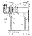
図1および図2は本発明の一実施例構成を示し、図1は一部を断面で示しかつ一部を省略した正面図、図2は上面図を表している。 1 and 2 show a configuration of an embodiment of the present invention. FIG. 1 shows a front view with a part shown in cross section and a part omitted, and FIG. 2 shows a top view.
符号1は基台、5はスライダ、6−iは電動機、7−iはねじ軸、8−iはナット、9−iはリニア・スケールを表している。 Reference numeral 1 denotes a base, 5 denotes a slider, 6-i denotes an electric motor, 7-i denotes a screw shaft, 8-i denotes a nut, and 9-i denotes a linear scale.
なお、図1において、図5に示した所の基台を支える脚部の水平部2や脚部の垂直部3は省略されている。また当然に存在する電動機6−2や当然に存在するリニア・スケール9−1は図1から省略されている。
In FIG. 1, the
図1,図2から判るように、ねじ軸7−iは基台1に対して非回転状態にかつ上下方向にも移動しないようにしっかり固定されている。ナット8−iは、夫々対応するねじ軸7−iと噛合しているが、スライダ5に対しては、対応する電動機6−iによって、ねじ軸7−iの廻りを回動できるようにされている。
As can be seen from FIGS. 1 and 2, the screw shaft 7-i is firmly fixed to the base 1 so as not to rotate and to move in the vertical direction. Each of the nuts 8-i meshes with the corresponding screw shaft 7-i, but the
即ち、電動機6−iの回転軸は、図示のカップリング10−iによって、図示の小歯車11−iの回転軸12−iに連結される。これによって、小歯車11−iは軸受13−iに支えられた回転軸12−iを介して電動機6−iにより回転駆動される。一方、ナット8−iは、スライダ5に対して回転可能に、かつスラスト受け14−iによってスライダ5に対して上下方向に移動できないように保持されている円筒状体15−iに、機械的に固定されている。言うまでもなく、円筒状体15−iの内周面はねじ軸7−iに対して図示しないガイドで支えられて僅かな間隙を介して対峙している。そして、前記小歯車11−iと噛合している大歯車16−iの中心部が前記円筒状体15−iの外周面に機械的に固定されている。
That is, the rotating shaft of the electric motor 6-i is connected to the rotating shaft 12-i of the illustrated small gear 11-i by the illustrated coupling 10-i. As a result, the small gear 11-i is rotationally driven by the electric motor 6-i via the rotary shaft 12-i supported by the bearing 13-i. On the other hand, the nut 8-i is mechanically attached to the cylindrical body 15-i that is held so as to be rotatable with respect to the
前記スラスト受け14−iは、スライダ5に嵌合している筒形環状体17−iの内周面に設けられており、前述の如く、円筒状体15−iが大歯車16−iによってねじ軸7−iの廻りを回転できるが当該円筒状体15−iが筒形環状体17−iに対して図示の上下方向には移動できないように、円筒状体15−iを保持している。
The thrust receiver 14-i is provided on the inner peripheral surface of the cylindrical annular body 17-i fitted to the
したがって、円筒状体15−iが電動機6−iによって小歯車11−iと大歯車16−iとを介して回転駆動され、あわせてナット8−iがねじ軸7−iの周面を回動させられる時には、スライダ5は前記筒形環状体17−iと一緒に、ねじ軸7−iに対しては非回転状態の下で上下動する。
Accordingly, the cylindrical body 15-i is rotationally driven by the electric motor 6-i via the small gear 11-i and the large gear 16-i, and the nut 8-i rotates around the peripheral surface of the screw shaft 7-i. When being moved, the
前述した如く、被加工体(図示せず)は、基台1とスライダ5との間に配置され、周知の如く、プレス型(図示せず)によってプレス加工される。
As described above, the workpiece (not shown) is disposed between the base 1 and the
図示の場合には、4個の電動機6−iが存在していて、プレス加工時にはスライダ5の4つの隅に対して夫々下降方向に力を加えてゆく。この間に、4個の電動機6−iの夫々は互いに独立に制御され、スライダ5が図示の場合には正しく水平状態を保つように働く。更に言えば、スライダ5が下降する各所定高さ位置毎に、スライダ5が正しく水平状態を保つように、電動機6−iが互いに独立に運転される。
In the illustrated case, there are four electric motors 6-i, and forces are applied in the downward direction to the four corners of the
言うまでもなく、被加工体をプレス加工するに当たっては、被加工体の形状によってスライダ5に偏心荷重が掛かることになり、スライダ5の水平状態を正しく保ちつつ下降させることが一般には困難である。
Needless to say, when the workpiece is pressed, an eccentric load is applied to the
しかし、本願出願人が既に特許文献1に記載している如く、プレス加工の試行段階において、スライダ5をきわめて低速度で下降せしめてゆき、偏心荷重の下でのプレス加工中で、スライダ5の高さ位置の各高さ毎に、4個のリニア・スケール9−iによってスライダ5の4つの隅の高さ位置が計測される。そして当該各高さ位置毎に、スライダ5の4つの隅の高さ位置が等しい値を示すようになるために、各電動機6−iに対してどのような駆動力を発揮せしめるべきかを決定する。即ち、各高さ位置毎に、個々の電動機6−iを制御する条件を決定し、電動機6−iを駆動するための回転数および/またはトルクを決定し、当該低速度のプレス加工中の下降の間に、各高さ位置毎にスライダ5が正しく水平状態を保つように電動機6−iを互いに独立に駆動する。
However, as already described in Patent Document 1 by the applicant of the present application, the
次いで、スライダ5の下降速度を少し速くして、同様に当該下降速度でのプレス加工中で、スライダ5が各高さ位置毎に、正しく水平状態になる運転制御の条件を決定する。このようにして、スライダ5の下降速度を少しづつ高めながら、最終的には、スライダ5がプレス加工中の所望される下降速度の下で、スライダ5が各高さ位置毎に正しく水平を保つための、各電動機毎の運転制御条件を決定する。
Next, the descending speed of the
この間の試行段階を、いわばティーチング加工段階とすると、当該ティーチング加工段階の最終時において、スライダ5が水平を保ちながらプレス加工が行われるための、各電動機6−i毎の運転制御条件が決定される。そして、次の本番加工段階においては、各電動機6−iに対して、当該電動機6−iが先に得られている運転制御条件の下で運転されるように互いに独立に制御を行ってゆく。
If the trial stage during this period is the so-called teaching process stage, the operation control condition for each motor 6-i is determined so that the press work is performed while the
前述のティーチング加工段階における各高さ位置毎でのスライダ5の4つの隅の高さ位置を計測するために、前述の如く、4個のリニア・スケール9−iが設けられている。当該各リニア・スケール9−iの下端は基台1にスケール・ブラケット固定部18−iによって固定されるが、上端は前記ねじ軸7−iの上端に取り付けられる支え棒19−iに対して上下方向に位置移動可能にスケール・ブラケット支持部20−iによって支えられる。即ち、各リニア・スケール9−iは、各ねじ軸7−iに沿うよう平行に、基台1に固定されるが、ねじ軸7−iがプレス加工の間に熱膨張および加工による変形を生じることがあることから、各リニア・スケール9−iがねじ軸7−iの当該熱膨張および加工による変形の影響を受けないように、スケール・ブラケット支持部20−iの所で、各リニア・スケール9−iの上端が上下動可能に支えられている。言うまでもなく、リニア・スケール9−iには目盛が刻まれていて、スライダ5の側から僅かに突出する指針が当該スライダ5の高さ位置の変化によって上下動する状態が計測される。
In order to measure the height positions of the four corners of the
図1に明瞭に示される構成においては、ねじ軸7−1とねじ軸7−2とは、ねじ切りの方向が互いに反対になっており、スライダ5を例えば下降せしめる際のナット8−1の回転駆動方向とナット8−2の回転駆動方向とは互いに反対の方向となるようにされる。
In the configuration clearly shown in FIG. 1, the screw shaft 7-1 and the screw shaft 7-2 are opposite to each other in the direction of threading, and the nut 8-1 is rotated when the
このように反対の方向に回転駆動されることによって、電動機6−iが同じ方向に回転されてナット8−1が一斉に同じ方向に回転駆動される場合に生じかねない無用な振動を極力防止するようにしている。 By rotating in the opposite direction in this way, unnecessary vibration that may occur when the motor 6-i is rotated in the same direction and the nuts 8-1 are simultaneously rotated in the same direction is prevented as much as possible. Like to do.
図3は駆動部を基台に固定的に取り付けた場合の他の実施例を示している。
図中の符号1ないし20は図1に対応しており、符号21は支持体であって複数個のねじ軸7−iの上部を相互に連結するように設けられた板状のものである。また符号22−iはスプライン軸であって図1に示す回転軸12−iに代わるスプラインが切られた回転軸、23−iはスプライン軸22−iに対する保持ブレーキ、24−iは支持環体であって回転駆動されるスプライン軸22−iと一緒に回転されるがスプライン軸22−iの軸上の任意の高さ位置に摺動された上でスプライン軸22−iを支持するもの、25−iは支持環体保持部であってスライダ5の上下動につれて支持環体24−iが回転可能にかつ当該支持環体24−iをスプライン軸22−iに対して上下方向に移動せしめるものである。なお、小歯車11−iは、前記支持環体24−iに固定されて、回転駆動されるスプライン軸22−iと当該支持環体24−iと一緒に回転駆動される。
FIG. 3 shows another embodiment in which the drive unit is fixedly attached to the base.
Reference numerals 1 to 20 in the figure correspond to those in FIG. 1, and
また前記支持体21は、図1に示される支え棒19−iが個々のねじ軸7−iの上端に個別に設けられていたものに代えて、複数個のねじ軸7−iの上端の相互の間を連結するように設けられている。このような板状の支持体21を設けることによって、大きい偏心荷重が掛かる場合でも、個々のねじ軸7−iが揺動する可能性を複数個存在するねじ軸7−iが一緒になって互いに抑止するように働くことになる。
Further, the
図3の構成の場合におけるプレス加工が行われる態様は、図1に示した場合と実質的に同じである。ただ、各駆動源である電動機6−iが基台1に固定的に取り付けられているだけである。 The mode in which the press working in the case of the configuration of FIG. 3 is performed is substantially the same as the case shown in FIG. However, the electric motor 6-i as each drive source is only fixedly attached to the base 1.
即ち、電動機6−iが回転駆動されると、スプライン軸22−iが回転し、支持環体24−iと小歯車11−iとが回転せしめられる。これによって、大歯車16−iが回転せしめられ、円筒状体15−iを介してナット8−iが回動せしめられる。このナット8−iの回動に対応して、スライダ5が例えば下降されプレス加工が行われる。このスライダ5の下降に対応して支持環体保持部25−iも下降し、支持環体24−iをスプライン軸22−iに沿って下降せしめてゆく。更に言えば、スライダ5の上下動につれて、支持環体24−i、小歯車11−i、大歯車16−i、ナット8−iが一斉に上下動する。
That is, when the electric motor 6-i is rotationally driven, the spline shaft 22-i rotates, and the support ring body 24-i and the small gear 11-i are rotated. As a result, the large gear 16-i is rotated, and the nut 8-i is rotated via the cylindrical body 15-i. In response to the rotation of the nut 8-i, the
図3に示す構成においては、ねじ軸7−1とねじ軸7−2とが同じ方向に切られたねじ軸となっているが、図1に示すように互いに反対の方向に切られたねじ軸を用いることが必須の要件ではない。 In the configuration shown in FIG. 3, the screw shaft 7-1 and the screw shaft 7-2 are screw shafts cut in the same direction, but the screws cut in opposite directions as shown in FIG. The use of axes is not an essential requirement.
図4はねじ軸をスライダに対して非回転状態で取り付けた場合の他の実施例を示している。
図中の符号1ないし18は図1に対応しており、また符号21は図3に存在するものとして示されている支持体に相当する支持体である。
FIG. 4 shows another embodiment in which the screw shaft is attached to the slider in a non-rotating state.
Reference numerals 1 to 18 in the figure correspond to FIG. 1, and
図4の構成の場合には、図1や図3に示した場合と基本的には同じであるが、ねじ軸7−iが夫々スライダ5に対して非回転状態でかつ軸方向に位置移動しない状態で固定されている。そして、ナット8−iは、基台1の側に当該基台1に対して回転可能でかつねじ軸7−iの軸方向に位置移動しない状態で固定されている。また電動機6−iは基台1に取り付けられている。
4 is basically the same as the case shown in FIGS. 1 and 3, but the screw shaft 7-i is not rotated with respect to the
電動機6−iが回転されると、小歯車11−iを介して大歯車16−iが回転駆動される。そして、図1に示した如く、ナット8−iが回転駆動され、ねじ軸7−iが基台1に対して一斉に上下動されることになる。即ち、ねじ軸7−iに固定されているスライダ5が上下動されることになる。勿論、図4に示される支持体21もスライダ5の上下動につれて上下動する。
When the electric motor 6-i is rotated, the large gear 16-i is rotationally driven via the small gear 11-i. Then, as shown in FIG. 1, the nut 8-i is rotationally driven, and the screw shaft 7-i is moved up and down simultaneously with respect to the base 1. That is, the
図4に示される場合には、リニア・スケール9−iの下端は基台1に固定され、リニア・スケール9−iの上端はスライダ5に沿うように配置されている。
In the case shown in FIG. 4, the lower end of the linear scale 9-i is fixed to the base 1, and the upper end of the linear scale 9-i is arranged along the
なお、図4においては電動機6−iが基台1に取り付けられているとしている。しかし、図4に示す構成において、図3に示す構成の場合のように、電動機6−iの存在位置とナット8−iの存在位置とが離れていてもよい。即ち、図4において電動機6−iがスライダ5の側に取り付けられていて、図3に示す構成の場合のようにスプライン軸22−iを介してナット8−iを回転駆動するようにしてもよい。
In FIG. 4, the electric motor 6-i is attached to the base 1. However, in the configuration shown in FIG. 4, the position where the electric motor 6-i is present and the position where the nut 8-i is present may be separated as in the case shown in FIG. 3. That is, the electric motor 6-i is attached to the
更に、図1や図3や図4においては、基台1がプレス装置の下部に位置するものとして示されている。しかし基台1がプレス装置と結合されている所の何らかの頑丈な固定部(図示せず)が存在しているような場合には、図1や図3や図4に天地を逆にして基台1自体を当該固定部と考えるようにしても良い。即ち、図1や図3の場合において、ねじ軸7−iが当該固定部に非回転状態に固定されるようにしても良い。図4の場合には、ナット8−iが当該固定部に回転可能状態に固定されることになる。 Furthermore, in FIG.1, FIG3 and FIG.4, the base 1 is shown as what is located in the lower part of a press apparatus. However, if there is any sturdy fixing part (not shown) where the base 1 is connected to the press device, the base is reversed in FIGS. 1, 3 and 4. The table 1 itself may be considered as the fixed part. That is, in the case of FIGS. 1 and 3, the screw shaft 7-i may be fixed to the fixing portion in a non-rotating state. In the case of FIG. 4, the nut 8-i is fixed to the fixing portion in a rotatable state.
また、図3や図4に示した板状の支持体21を、図3や図4に示す状態の支持体21よりも充分に頑丈な構造体として、あるいは基台1にしっかりと固定された構造体として、図3や図4に示される駆動源としての電動機6−iが当該構造体に固定的に取り付けられるようにされていても良い。
Further, the plate-
1:基台
5:スライダ
6:電動機
7:ねじ軸
8:ナット
9:リニア・スケール
11:小歯車
14:スラスト受け
15:円筒状体
16:大歯車
17:筒形環状体
18:スケール・ブラケット固定部
20:スケール・ブラケット支持部
1: Base 5: Slider 6: Electric motor 7: Screw shaft 8: Nut 9: Linear scale 11: Small gear 14: Thrust receiver 15: Cylindrical body 16: Large gear 17: Cylindrical annular body 18: Scale bracket Fixed part 20: Scale bracket support part
Claims (7)
前記複数個のねじ軸が、前記基台に対してまたは基台に対して固定されている固定部に対して非回転状態に固定されると共に、
前記スライダは、前記複数個のねじ軸に螺合して当該ねじ軸の夫々に対して回転可能に支えられた複数個のナットを、当該スライダに対して回転可能状態にかつ前記ねじ軸の方向に非移動状態に、保持しており、
かつ前記複数個のナットは夫々駆動源によって回動され、
更に、前記スライダは、当該スライダを貫通する孔として、前記複数個のねじ軸が貫通する孔のみを有するよう構成され、
偶数個ずつ対となって存在する前記ねじ軸の一方は対となる他方のねじ軸のねじの方向とは反対のねじ方向となるよう形成されたねじを持つよう構成され、かつ、対応する偶数個のナットの一方は対となる他方のナットの回転方向とは反対方向に回動駆動され、
前記複数個のねじ軸は、当該複数個のねじ軸によって、前記スライダが前記基台と平行な方向に揺動する位置変動を抑止するよう構成されている
ことを特徴とするプレス装置。 A base, provided with several screw shaft double that exist perpendicular to the base board, and a slider that extends in a direction perpendicular to the base and parallel to and the screw shaft, and the base In a press device in which a workpiece is placed in a space between the slider and the workpiece is pressed by a pressing force associated with the movement of the slider.
With prior several screw shaft Kifuku is fixed to a non-rotating state with respect to the fixed portion that is fixed relative or base with respect to the base,
The slider, the screwed before several screw shaft Kifuku with double several nuts, supported rotatably relative to each of the screw shaft and the screw in a rotatable state relative to the slider Held in a non-moving state in the direction of the axis,
And several nuts before Kifuku is rotated by respective drive sources,
Furthermore, the slider is a hole penetrating the slider, before several screw shaft Kifuku is configured to have only holes through,
One of the screw shafts present in pairs is configured to have a screw formed so as to have a screw direction opposite to the screw direction of the other screw shaft and the corresponding even number. One of the nuts is rotationally driven in a direction opposite to the rotational direction of the other nut,
Before several screw shaft Kifuku by those plurality few screw shaft, the slider is characterized in that it is configured so as to suppress the position variation swings the base in a direction parallel press apparatus.
当該複数個のナットの回動によって、前記スライダが前記基台に近づく方向と遠ざかる方向とに移動される
ことを特徴とする請求項1記載のプレス装置。 Several nuts before Kifuku, respectively, is supported on the slider is rotated by a driving source which moves together with the slider,
By the rotation of those plurality few nuts, the press apparatus according to claim 1, wherein said slider is moved in the direction away a direction approaching the base.
当該複数個のナットの回動によって、前記スライダが前記基台に近づく方向と遠ざかる方向とに移動される
ことを特徴とする請求項1記載のプレス装置。 Several nuts before Kifuku, respectively, are rotated by a driving source is fixed and supported on or the fixing portion is supported on the base,
By the rotation of those plurality few nuts, the press apparatus according to claim 1, wherein said slider is moved in the direction away a direction approaching the base.
ことを特徴とする請求項1記載のプレス装置。 The plurality of screw shafts are present at the end opposite to the end fixed to the base or the fixing portion, and the support or the base is present so as to connect the plurality of screw shafts to each other. The press device according to claim 1, wherein the press device is supported by a support member that is fixed to the support member.
当該スケールは、前記ねじ軸の夫々に対応して設けられており、かつ当該ねじ軸に対応する前記夫々のナットが前記スライダに支えられて存在する位置の近傍における当該スライダの前記移動位置を計測する
ことを特徴とする請求項1記載のプレス装置。 A scale that measures the moving position of the slider that moves relative to the base;
The scale is provided corresponding to each of the screw shafts, and the moving position of the slider in the vicinity of the position where the nuts corresponding to the screw shafts are supported by the slider is measured. The press apparatus according to claim 1, wherein:
一端が前記基台に対して固定的に取り付けられると共に、
他端が、前記ねじ軸が前記基台にまたは前記固定部に固定されていない側の端に、または前記ねじ軸が基台にまたは前記固定部に固定されていない側の端で複数個のねじ軸相互の間を連結するように存在する支持体に、または前記ねじ軸が基台にまたは前記固定部に固定されていない側の端を支持して前記基台に対して固定する支持体に、前記ねじ軸の長手方向に位置移動可能に支えられている
ことを特徴とする請求項5記載のプレス装置。 Each of the plurality of scales is
One end is fixedly attached to the base,
The other end is plural at the end on the side where the screw shaft is not fixed to the base or the fixing portion, or at the end on the side where the screw shaft is not fixed to the base or the fixing portion. A support that is fixed to the base by supporting the end that is not fixed to the base or to the fixing portion on a support that exists so as to connect the screw shafts to each other. The press device according to claim 5, wherein the press device is supported so as to be movable in the longitudinal direction of the screw shaft.
該スライダに対して垂直に存在する1つまたは複数個のねじ軸とを備え、前記基台と前記スライダとの間の空間に被加工体が載置されて前記スライダの移動に伴う加圧力によって当該被加工体がプレス加工されるプレス装置において、
前記1つまたは複数個のねじ軸が、前記スライダに対して非回転状態に固定されると共に、
前記基台または該基台に対して固定されている固定部が、前記1つまたは複数個のねじ軸に螺合して当該ねじ軸の夫々に対して回転可能に支えられた1つまたは複数個のナットを、当該基台または当該固定部に対して回転可能状態にかつ前記ねじ軸の方向に非移動状態に、保持しており、
かつ前記1つまたは複数個のナットは夫々駆動源によって回動され、
更に、前記基台または前記固定部は、当該基台または当該固定部を貫通する孔として、前記1つまたは複数個のねじ軸が貫通する孔のみを有するよう構成され、
前記1つまたは複数個のねじ軸は、当該1つまたは複数個のねじ軸によって、前記スライダが前記基台と平行な方向に揺動する位置変動を抑止するよう構成されている
ことを特徴とするプレス装置。 A base and a slider provided in parallel to the base;
One or a plurality of screw shafts that exist perpendicularly to the slider, and a workpiece is placed in a space between the base and the slider, and is subjected to pressure applied by the movement of the slider In a press device in which the workpiece is pressed,
The one or more screw shafts are fixed in a non-rotating state with respect to the slider;
One or a plurality of fixed portions fixed to the base or the base are screwed onto the one or the plurality of screw shafts and are rotatably supported with respect to each of the screw shafts. Holding the nuts in a rotatable state with respect to the base or the fixed portion and in a non-moving state in the direction of the screw shaft,
And each of the one or more nuts is rotated by a driving source,
Furthermore, the base or the fixing part is configured to have only a hole through which the one or a plurality of screw shafts pass as a hole penetrating the base or the fixing part.
The one or the plurality of screw shafts are configured to suppress positional fluctuations in which the slider swings in a direction parallel to the base by the one or more screw shafts. Press machine.
Priority Applications (1)
| Application Number | Priority Date | Filing Date | Title |
|---|---|---|---|
| JP2007104572A JP5179772B2 (en) | 2007-04-12 | 2007-04-12 | Press machine |
Applications Claiming Priority (1)
| Application Number | Priority Date | Filing Date | Title |
|---|---|---|---|
| JP2007104572A JP5179772B2 (en) | 2007-04-12 | 2007-04-12 | Press machine |
Publications (2)
| Publication Number | Publication Date |
|---|---|
| JP2008260041A JP2008260041A (en) | 2008-10-30 |
| JP5179772B2 true JP5179772B2 (en) | 2013-04-10 |
Family
ID=39982931
Family Applications (1)
| Application Number | Title | Priority Date | Filing Date |
|---|---|---|---|
| JP2007104572A Active JP5179772B2 (en) | 2007-04-12 | 2007-04-12 | Press machine |
Country Status (1)
| Country | Link |
|---|---|
| JP (1) | JP5179772B2 (en) |
Families Citing this family (4)
| Publication number | Priority date | Publication date | Assignee | Title |
|---|---|---|---|---|
| DE102008060043B3 (en) * | 2008-12-02 | 2010-07-29 | Germas Ag | screw press |
| EP3088172B1 (en) * | 2015-04-30 | 2021-11-03 | G.F. S.p.A. | Compression press and use thereof |
| CN108294598A (en) * | 2018-04-04 | 2018-07-20 | 江苏楷益智能科技有限公司 | One cup juice extractor transmission mechanism |
| CN108656595A (en) * | 2018-04-13 | 2018-10-16 | 安徽天水液压机床科技有限公司 | A kind of closed double-point servo-pressing machine |
Family Cites Families (5)
| Publication number | Priority date | Publication date | Assignee | Title |
|---|---|---|---|---|
| JPH05329692A (en) * | 1992-05-29 | 1993-12-14 | Janome Sewing Mach Co Ltd | Electric press |
| JPH06170589A (en) * | 1992-07-30 | 1994-06-21 | M Tex Matsumura Kk | Motor-driven press device |
| JPH0819895A (en) * | 1994-07-01 | 1996-01-23 | Nikko Tokki Kk | Full motor driven mechanical press |
| JPH10202564A (en) * | 1997-01-23 | 1998-08-04 | Shibaura Eng Works Co Ltd | Linear movement type robot |
| JP2003334694A (en) * | 2002-05-20 | 2003-11-25 | Amada Eng Center Co Ltd | Driver for press |
-
2007
- 2007-04-12 JP JP2007104572A patent/JP5179772B2/en active Active
Also Published As
| Publication number | Publication date |
|---|---|
| JP2008260041A (en) | 2008-10-30 |
Similar Documents
| Publication | Publication Date | Title |
|---|---|---|
| US20100260569A1 (en) | Mill bed | |
| JP5179772B2 (en) | Press machine | |
| RU2011100834A (en) | ELECTRONICALLY CONTROLLED BEAM LOADING SYSTEM | |
| JP2988727B2 (en) | Engraving head stand | |
| JP2010052332A (en) | Brittle material breaking device | |
| CN1991592B (en) | Object stage device | |
| JP2015054341A (en) | High pressure twist molding machine | |
| JP2014530764A (en) | Press machine | |
| JP3357358B2 (en) | Press machine | |
| JP4862505B2 (en) | Forging apparatus and forging method | |
| JP2010184269A (en) | Rotating type plastic working apparatus | |
| JP4880956B2 (en) | Press drive device | |
| JP4672284B2 (en) | Electric press device | |
| JP2012030234A (en) | Rotational plastic working apparatus and operation method for rotational plastic working apparatus | |
| JP2017177124A (en) | Manufacturing device for wheel rim for automobile | |
| JP2003159613A (en) | Capstan for manipulating slitting tool | |
| CN206794209U (en) | A kind of linear bearing endoporus machine | |
| JP2010184270A (en) | Rotating type plastic working apparatus | |
| JP4899458B2 (en) | Press machine | |
| JP2000343286A (en) | Slide drive device of machine press | |
| JP2964219B2 (en) | Roll support device under the roll bending device | |
| JP6909696B2 (en) | Rolling board | |
| CA2662352A1 (en) | Improved mill bed | |
| JP2005299773A (en) | Feed screw unit and stage device | |
| JP2010172904A (en) | Press machine and slide structure of ram |
Legal Events
| Date | Code | Title | Description |
|---|---|---|---|
| A621 | Written request for application examination |
Free format text: JAPANESE INTERMEDIATE CODE: A621 Effective date: 20100212 |
|
| RD02 | Notification of acceptance of power of attorney |
Free format text: JAPANESE INTERMEDIATE CODE: A7422 Effective date: 20100901 |
|
| A977 | Report on retrieval |
Free format text: JAPANESE INTERMEDIATE CODE: A971007 Effective date: 20120203 |
|
| A131 | Notification of reasons for refusal |
Free format text: JAPANESE INTERMEDIATE CODE: A131 Effective date: 20120306 |
|
| A521 | Request for written amendment filed |
Free format text: JAPANESE INTERMEDIATE CODE: A523 Effective date: 20120507 |
|
| TRDD | Decision of grant or rejection written | ||
| A01 | Written decision to grant a patent or to grant a registration (utility model) |
Free format text: JAPANESE INTERMEDIATE CODE: A01 Effective date: 20130108 |
|
| A61 | First payment of annual fees (during grant procedure) |
Free format text: JAPANESE INTERMEDIATE CODE: A61 Effective date: 20130110 |
|
| R150 | Certificate of patent or registration of utility model |
Ref document number: 5179772 Country of ref document: JP Free format text: JAPANESE INTERMEDIATE CODE: R150 |
|
| R250 | Receipt of annual fees |
Free format text: JAPANESE INTERMEDIATE CODE: R250 |
|
| R250 | Receipt of annual fees |
Free format text: JAPANESE INTERMEDIATE CODE: R250 |
|
| R250 | Receipt of annual fees |
Free format text: JAPANESE INTERMEDIATE CODE: R250 |
|
| R250 | Receipt of annual fees |
Free format text: JAPANESE INTERMEDIATE CODE: R250 |
|
| R250 | Receipt of annual fees |
Free format text: JAPANESE INTERMEDIATE CODE: R250 |
|
| R250 | Receipt of annual fees |
Free format text: JAPANESE INTERMEDIATE CODE: R250 |
|
| R250 | Receipt of annual fees |
Free format text: JAPANESE INTERMEDIATE CODE: R250 |
|
| R250 | Receipt of annual fees |
Free format text: JAPANESE INTERMEDIATE CODE: R250 |
|
| R250 | Receipt of annual fees |
Free format text: JAPANESE INTERMEDIATE CODE: R250 |