JP5178478B2 - Sheet feeding apparatus and image forming apparatus - Google Patents
Sheet feeding apparatus and image forming apparatus Download PDFInfo
- Publication number
- JP5178478B2 JP5178478B2 JP2008303390A JP2008303390A JP5178478B2 JP 5178478 B2 JP5178478 B2 JP 5178478B2 JP 2008303390 A JP2008303390 A JP 2008303390A JP 2008303390 A JP2008303390 A JP 2008303390A JP 5178478 B2 JP5178478 B2 JP 5178478B2
- Authority
- JP
- Japan
- Prior art keywords
- sheet
- side end
- sheet feeding
- image forming
- width direction
- Prior art date
- Legal status (The legal status is an assumption and is not a legal conclusion. Google has not performed a legal analysis and makes no representation as to the accuracy of the status listed.)
- Active
Links
- 230000001105 regulatory effect Effects 0.000 claims description 46
- 238000000926 separation method Methods 0.000 description 5
- 238000010586 diagram Methods 0.000 description 4
- 230000015572 biosynthetic process Effects 0.000 description 1
- 230000007423 decrease Effects 0.000 description 1
- 230000001678 irradiating effect Effects 0.000 description 1
- 238000000034 method Methods 0.000 description 1
Images


Classifications
-
- B—PERFORMING OPERATIONS; TRANSPORTING
- B65—CONVEYING; PACKING; STORING; HANDLING THIN OR FILAMENTARY MATERIAL
- B65H—HANDLING THIN OR FILAMENTARY MATERIAL, e.g. SHEETS, WEBS, CABLES
- B65H1/00—Supports or magazines for piles from which articles are to be separated
- B65H1/04—Supports or magazines for piles from which articles are to be separated adapted to support articles substantially horizontally, e.g. for separation from top of pile
-
- B—PERFORMING OPERATIONS; TRANSPORTING
- B65—CONVEYING; PACKING; STORING; HANDLING THIN OR FILAMENTARY MATERIAL
- B65H—HANDLING THIN OR FILAMENTARY MATERIAL, e.g. SHEETS, WEBS, CABLES
- B65H9/00—Registering, e.g. orientating, articles; Devices therefor
- B65H9/04—Fixed or adjustable stops or gauges
-
- B—PERFORMING OPERATIONS; TRANSPORTING
- B65—CONVEYING; PACKING; STORING; HANDLING THIN OR FILAMENTARY MATERIAL
- B65H—HANDLING THIN OR FILAMENTARY MATERIAL, e.g. SHEETS, WEBS, CABLES
- B65H2405/00—Parts for holding the handled material
- B65H2405/10—Cassettes, holders, bins, decks, trays, supports or magazines for sheets stacked substantially horizontally
- B65H2405/11—Parts and details thereof
- B65H2405/114—Side, i.e. portion parallel to the feeding / delivering direction
-
- B—PERFORMING OPERATIONS; TRANSPORTING
- B65—CONVEYING; PACKING; STORING; HANDLING THIN OR FILAMENTARY MATERIAL
- B65H—HANDLING THIN OR FILAMENTARY MATERIAL, e.g. SHEETS, WEBS, CABLES
- B65H2511/00—Dimensions; Position; Numbers; Identification; Occurrences
- B65H2511/10—Size; Dimensions
- B65H2511/12—Width
-
- B—PERFORMING OPERATIONS; TRANSPORTING
- B65—CONVEYING; PACKING; STORING; HANDLING THIN OR FILAMENTARY MATERIAL
- B65H—HANDLING THIN OR FILAMENTARY MATERIAL, e.g. SHEETS, WEBS, CABLES
- B65H2511/00—Dimensions; Position; Numbers; Identification; Occurrences
- B65H2511/20—Location in space
- B65H2511/22—Distance
-
- B—PERFORMING OPERATIONS; TRANSPORTING
- B65—CONVEYING; PACKING; STORING; HANDLING THIN OR FILAMENTARY MATERIAL
- B65H—HANDLING THIN OR FILAMENTARY MATERIAL, e.g. SHEETS, WEBS, CABLES
- B65H2801/00—Application field
- B65H2801/03—Image reproduction devices
- B65H2801/06—Office-type machines, e.g. photocopiers
Description
本発明は、シート給送装置及び画像形成装置に関し、特にシート支持部に支持されたシートの幅方向の側端位置を規制する側端規制部機構の構成に関する。 The present invention relates to a sheet feeding device and an image forming apparatus, and more particularly to a configuration of a side end regulating unit mechanism that regulates a side end position in a width direction of a sheet supported by a sheet supporting unit.
今日、複写機、プリンタ、ファクシミリ等の画像形成装置においては、シート給送装置から画像形成部にシートを給送して画像を形成するようにしたものが広く普及している。そして、このようなシート給送装置としては、装置本体にシート支持部である給紙カセットを着脱自在に装着し、給紙カセットに収納支持されたシートを画像形成部に自動給送するようにしているのが一般的である。 2. Description of the Related Art Today, image forming apparatuses such as copying machines, printers, and facsimiles are widely used in which an image is formed by feeding a sheet from a sheet feeding apparatus to an image forming unit. As such a sheet feeding apparatus, a sheet feeding cassette as a sheet supporting unit is detachably attached to the apparatus main body, and a sheet stored and supported in the sheet feeding cassette is automatically fed to the image forming unit. It is common.
このようなシート給送装置に用いられる給紙カセットとしては、例えば、シートを積載してシート給送ローラに押し付ける中板を昇降可能に設けたものがある。さらに、このような中板を設けた給紙カセットには、異なるサイズのシートを収納することができるように中板上に積載収納されたシートのシート給送方向後端(以下、後端という)の位置を規制する後端規制部材が設けられている。また、シートのシート給送方向と直交する方向(以下、幅方向という)の側端位置を規制する側端規制部材が設けられている。 As a sheet feeding cassette used in such a sheet feeding apparatus, for example, there is one in which a middle plate that stacks sheets and presses them against a sheet feeding roller is provided so as to be movable up and down. Further, the sheet feeding cassette provided with such a middle plate has a rear end in the sheet feeding direction (hereinafter referred to as a rear end) of the sheets stacked and stored on the middle plate so that sheets of different sizes can be stored. ) Is provided. Further, a side end regulating member that regulates a side end position of a sheet in a direction orthogonal to the sheet feeding direction (hereinafter referred to as a width direction) is provided.
このような給紙カセットにおいては、側端規制部材によってシートの側端を規制し、後端規制部材によって後端を規制し、シートの先端位置を常に所定の位置になるようにしている。これにより、給紙カセットを装置本体に収納した際、シートのサイズに拘らず、安定したシートの給送を行うことができる。 In such a sheet feeding cassette, the side edge of the sheet is regulated by the side edge regulating member, the trailing edge is regulated by the trailing edge regulating member, and the leading edge position of the sheet is always set to a predetermined position. As a result, when the sheet feeding cassette is stored in the apparatus main body, stable sheet feeding can be performed regardless of the sheet size.
ところで、近年、レーザービームプリンタ等の画像形成装置において、シートの幅方向の印字余白を均等にするため、給紙カセット内のシートと画像形成装置における画像形成位置とで、幅方向の位置整合をとるようにしたものがある。しかし、この幅方向の位置整合は、部品の加工精度及び組立の精度の影響を受けることから、完全に両者の幅方向の位置を整合させることは難しい。 Incidentally, in recent years, in an image forming apparatus such as a laser beam printer, in order to make the printing margin in the sheet width direction uniform, the sheet in the paper feed cassette and the image forming position in the image forming apparatus are aligned in the width direction. There is something that I tried to take. However, since the position alignment in the width direction is affected by the processing accuracy of the parts and the accuracy of assembly, it is difficult to completely align the positions in the width direction of both.
そこで、給紙カセット内のシートと画像形成位置との位置整合をとるため、例えば対向して設けられた側端規制部材全体を幅方向に移動可能とし、側端規制部材全体を幅方向に移動させて調整するようにしたものがある(特許文献1参照)。なお、このような側端規制部材の調整を可能にするため、側端規制部材のシートの規制を行う面の反対側(以下、外側という)には空間が設けられている。 Therefore, in order to align the position of the sheet in the sheet feeding cassette and the image forming position, for example, the entire side end regulating member provided oppositely can be moved in the width direction, and the entire side end regulating member is moved in the width direction. There is one that is adjusted by adjusting (see Patent Document 1). In order to enable such adjustment of the side end regulating member, a space is provided on the side opposite to the surface of the side end regulating member that restricts the sheet (hereinafter referred to as the outside).
しかし、このような従来のシート給送装置及びこれを備えた画像形成装置において、側端規制部材全体を幅方向に調整可能な構成にした場合には、側端規制機構全体をシフトさせるための移動機構が必要になり、構成が複雑になる。また、側端規制部材全体の外側に調整代としての空間を設けなければならないため、装置全体が大きくなり、コストも増加する。 However, in such a conventional sheet feeding device and an image forming apparatus including the same, when the entire side end regulating member is adjustable in the width direction, the entire side end regulating mechanism is shifted. A moving mechanism is required, and the configuration is complicated. Further, since a space as an adjustment allowance must be provided outside the entire side end regulating member, the entire apparatus becomes large and the cost increases.
また、側端規制部材をシートサイズに応じて幅方向に移動させる場合、シートサイズに応じた側端規制部材の位置の目安となる刻印を、給紙カセットあるいはその周辺に設ける場合がある。この場合、側端規制部材のみをシート幅方向に調整すると、目安となる刻印と側端規制部材の位置がずれてしまい、側端規制部材をシートサイズに応じた位置にセットすることができなくなる。このため、側端規制部材を幅方向に移動させる場合、目安となる刻印も併せて移動調整する必要が生じ、構成が複雑になる。 In addition, when the side end regulating member is moved in the width direction according to the sheet size, there is a case where an inscription serving as a guide for the position of the side end regulating member according to the sheet size is provided on the sheet feeding cassette or the periphery thereof. In this case, if only the side end regulating member is adjusted in the sheet width direction, the reference marking and the position of the side end regulating member are shifted, and the side end regulating member cannot be set at a position corresponding to the sheet size. . For this reason, when the side end regulating member is moved in the width direction, it is necessary to move and adjust the reference mark as well, which complicates the configuration.
そこで、本発明は、このような現状に鑑みてなされたものであり、簡単な構成で、かつ低コストでシート支持部に支持されたシートと、シートの画像形成位置との位置整合をとることのできるシート給送装置及び画像形成装置を提供することを目的とする。 Therefore, the present invention has been made in view of such a current situation, and takes a positional alignment between a sheet supported by the sheet support portion and an image forming position of the sheet with a simple configuration and at a low cost. An object of the present invention is to provide a sheet feeding apparatus and an image forming apparatus capable of performing the above.
本発明は、複数のシートを支持するシート支持部と、シート給送方向と直交する幅方向に設けられ、前記シート支持部に支持されたシートの幅方向の端部に当接して位置を規制する側端規制機構と、前記シート支持部に支持されて前記側端規制機構により規制されたシートの最上位のシートを送り出すシート給送部と、を備えたシート給送装置において、前記側端規制機構は、シートを給送する際のシートの幅方向の基準となる基準面を有する基準側端規制部と、前記基準側端規制部に対向して設けられ、シートを前記基準面に向けて付勢するためのシート押圧部材を備えた側端規制部と、を備え、前記基準面を、下側を支点として揺動可能に支持し、前記基準面の揺動角度を変更する調整部を設けたことを特徴とするものである。 The present invention provides a sheet support portion that supports a plurality of sheets and a width direction orthogonal to the sheet feeding direction, and abuts against an end portion in the width direction of the sheet supported by the sheet support portion to regulate the position. In the sheet feeding apparatus, comprising: a side edge regulating mechanism that performs a sheet feeding unit that feeds the uppermost sheet supported by the sheet support part and regulated by the side edge regulating mechanism. The restricting mechanism is provided to face the reference side end restricting portion, the reference side end restricting portion having a reference surface serving as a reference in the width direction of the sheet when feeding the sheet, and directing the sheet toward the reference surface. And a side end restricting portion having a sheet pressing member for biasing, and an adjustment portion that supports the reference surface so as to be swingable with the lower side as a fulcrum, and changes a swing angle of the reference surface Is provided.
本発明のように、調整部により、シートを給送する際のシートの幅方向の基準となる基準面の揺動角度を変更することにより、簡単な構成で、かつ低コストでシート支持部に支持されたシートと、シートの画像形成位置との位置整合をとることができる。 As in the present invention, the adjustment unit changes the swing angle of the reference surface, which is the reference in the width direction of the sheet when feeding the sheet, to the sheet support unit with a simple configuration and low cost. Positional alignment between the supported sheet and the image forming position of the sheet can be achieved.
以下、本発明を実施するための最良の形態について図面を用いて詳細に説明する。 The best mode for carrying out the present invention will be described below in detail with reference to the drawings.
図1は、本発明の実施の形態に係るシート給送装置を備えた画像形成装置の一例であるプリンタの概略構成を示す図である。 FIG. 1 is a diagram illustrating a schematic configuration of a printer which is an example of an image forming apparatus including a sheet feeding device according to an embodiment of the present invention.
図1において、50はプリンタ、51は装置本体であるプリンタ本体、52はプリンタ本体51に設けられ、電子写真方式により画像形成を行う画像形成部、54は画像形成部52にシートSを給送するシート給送装置である。
In FIG. 1, 50 is a printer, 51 is a printer main body which is an apparatus main body, 52 is provided in the printer
ここで、画像形成部52はトナー像を形成する感光体ドラム53、感光体ドラム53に形成されたトナー像をシートSに転写する転写ローラ65などを備えている。そして、このような構成の画像形成部52において、画像形成動作が開始されると、まず不図示のレーザー露光装置から画像信号に応じた光が、感光体ドラム53に照射される。そして、このような画像信号に応じた光が照射されることにより、感光体ドラム上に潜像が形成される。次に、この感光体ドラム上の潜像は、現像手段により供給されたトナーにより現像され、トナー像として可視化される。
Here, the
シート給送装置54は、プリンタ本体51に着脱自在に装着され、シートを積載するシート積載部である給紙カセット1と、給紙カセット1に収納されたシートSを給送するシート給送部を構成する給紙ローラ54aを備えている。ここで、給紙カセット1は、シートSを積載する上下方向に移動可能な中板4と、シートSのシート給送方向に対して直交する幅方向の両端位置を規制する後述する図2に示す側端規制部材、シートSの後端を規制する後端規制部材7を備えている。
The
また、給紙カセット1のシート給送方向下流側には、給紙ローラ54aに圧接する分離パッド60が設けられており、この分離パッド60は分離パッドばね61により給紙ローラ54aに圧接するようになっている。そして、このようなシート給送装置54においては、画像形成の際には給紙ローラ54aにより給紙カセット1からシートSを送り出し、この後、シートSを給紙ローラ54aに圧接している分離パッド60により1枚ずつ分離するようにしている。
A
次に、このような構成のプリンタ50における画像形成動作について説明する。
Next, an image forming operation in the
プリント開始信号が入力されると、給紙カセット1に積載されたシートSが、給紙ローラ54aとの摩擦により送り出される。この後、シートSは分離パッドばね61により付勢されて給紙ローラ54aに圧接している分離パッド60によって1枚ずつ分離され、給送される。
When the print start signal is input, the sheets S stacked on the
次に、シートSは、搬送ローラ63により搬送されてレジストローラ対64に達し、レジストローラ対64によりシートSの先端が揃えられる。なお、レジストローラ対64に達する前、シートSの通過を不図示のフォトセンサが検知すると、不図示のレーザー露光装置は感光体ドラム53にレーザー光を照射する。
Next, the sheet S is conveyed by the conveying
これにより、感光体ドラム上には静電潜像が形成され、この静電潜像をトナーによって現像することにより、静電潜像を可視化する。この後、可視化された感光体ドラム上のトナー像は、転写部を構成する転写ローラ65に感光体ドラム53に形成されたトナー像と逆極性の電圧を印加することにより、シートSに転写される。
Thereby, an electrostatic latent image is formed on the photosensitive drum, and the electrostatic latent image is visualized by developing the electrostatic latent image with toner. Thereafter, the visualized toner image on the photosensitive drum is transferred to the sheet S by applying a voltage having a polarity opposite to that of the toner image formed on the
次に、トナー像が転写されたシートSは定着部66に搬送され、定着部66を通過する際に加圧及び加熱され、トナー像がシート上に永久定着される。そして、トナー像が定着されたシートSは排紙ローラ対67〜69により、排紙カセット70の上に積載される。
Next, the sheet S to which the toner image has been transferred is conveyed to the
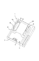
ここで、給紙カセット1は、図2に示すように、各種サイズのシートを積載収納支持するシート収容空間2を有するカセット本体3と、シートを支持するシート支持部であるカセット本体3に昇降可能に設けられ、シートを積載する中板4を備えている。また、給紙カセット1は、シートの後端の位置を規制する後端規制部材7を備えている。
Here, as shown in FIG. 2, the
さらに、給紙カセット1は、シートのシート給送方向と直交する幅方向の一方の側端位置を規定する基準側端規制部である側端基準部5と、側端基準部5に対向して設けられ、シートの幅方向の他方の側端位置を規制する側端規制部6とを備えている。そして、この側端基準部5と、側端規制部6とにより、給紙カセット1より支持されたシートの幅方向の側端位置を規制する側端規制機構が構成される。
Further, the
側端基準部5、側端規制部6、後端規制部材7はシートの各種サイズに応じて移動可能な構成となっている。側端基準部5と側端規制部6は、図3の(a)及び(b)に示すように、カセット本体3の底面19に設けられたピニオン10に噛合するラック11,12を備えており、このラック11,12とピニオン10により互いに反対方向に同じ量移動する。なお、図3の(a)は、A4サイズのシートを収納するときの側端基準部5、側端規制部6及び後端規制9の位置を示し、図3の(b)は、A4サイズのシートを収納するときの側端基準部5、側端規制部6及び後端規制9の位置を示している。
The side
また、シートを積載する中板4は不図示の昇降機構により、図4の(a)及び(b)に示すように給紙カセット1の底面19と平行な状態で昇降可能に設けられる。そして、シートが順次給送され、シートSの最上位シートSaの位置が所定の高さ以下になったことを不図示のシート上面センサが検知すると、図4の(b)に示すように、中板4が上昇する。これにより、最上位シートSaの位置は一定の高さ範囲内に保たれる。
Further, the
ところで、図2に示すように、側端規制部6には、シートの側端(端部)と圧接し、シートを付勢して側端基準部5へ押し当てる押圧部材であるシート押圧部材8が幅方向に移動可能に、かつシート給送方向に沿って2つ(複数)設けられている。また、シート押圧部材8と側端規制部6の側壁部6aとの間には、図5に示すように、シート押圧部材8を側端基準部材側に付勢する付勢部材である規制バネ9が上下方向に設けられている。
Incidentally, as shown in FIG. 2, a sheet pressing member that is a pressing member that presses against the side end (end) of the sheet and biases the sheet against the side
そして、カセット本体内にシートSが収納されているとき、シートSは上下方向に配された規制バネ9により付勢されたシート押圧部材8によって圧接される。これにより、シートSは、図4に示すように、側端基準部5のシートSと当接し、シートを給送する際のシートの幅方向の基準となる基準面である、シート当接面を有する側壁部5aに弾性的に押し当てられる。この結果、シートSの幅方向の一方の側端位置、すなわちシートの画像形成位置との位置整合の基準となるシートSの一方の側端位置は側端基準部5の位置に倣う。
When the sheet S is stored in the cassette body, the sheet S is pressed by a
このようにシートSの幅方向の側端位置が側端基準部5の位置に倣うことにより、シート給送の際、シートは側端基準部5を基準とする片側基準で給送される。そして、このように側端基準部5を基準としてシートを給送するようにすることにより、シートとプリンタ内の転写部における画像形成(転写)位置との位置整合をとることができる。
As described above, the side edge position in the width direction of the sheet S follows the position of the side
また、この側端基準部5には、図6に示すように、給紙カセット1の底面19に対する側壁部5aの角度を調整する角度調整部材14がスライド操作可能に設けられている。この角度調整部材14は側端基準部5の給紙カセット1の底面19に対して平行な底板5bの上面側から操作できるようになっている。
Further, as shown in FIG. 6, the side
なお、本実施の形態において、この角度調整部材14は、シートの積載の邪魔にならないように、側端基準部5の底板5bに形成された操作用開口部5cの内方に位置している。また、本実施の形態において、角度調整部材14は図7に示すように上面が傾斜しており、この角度調整部材14の上面に接する(係合する)底板5bの底面5dには傾斜面が形成されている。
In the present embodiment, the
これにより、図7の(a)に示す位置にある角度調整部材14を矢印方向に移動操作すると、図7の(b)に示すように、角度調整部材14が側端基準部5の底面5dと、カセット本体3の底面19との間に進入する。この結果、側端基準部5は、側端基準部5の底板5bの、上部に側壁部5aが垂設された角部を支点として揺動し、側端基準部5の側壁部5aが図8に示すようにカセット本体3の底面19に対して傾く。
Accordingly, when the
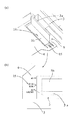
このように、揺動可能な側端基準部5の側壁部5aが給紙カセット1の底面19に対して傾いた場合、シートSがシート押圧部材8によって幅方向に付勢されると、図9の(a)に示すように、給送される最上位シートSaの幅方向の側端位置はΔd移動する。そして、このようにシートSが移動することにより、給送されるシートSaに対する印字位置もΔd移動する。
As described above, when the
つまり、角度調整部材14の操作によって側端基準部5を傾けることにより、シートの幅方向の基準位置を調整(変更)することができる。なお、このように側端基準部5が傾いた場合でも、図3に示す側端基準部5のラック11がピニオン10から離間することはないので、この状態で、側端基準部5の側壁部5aにシートが押し付けられても側端基準部5が幅方向に移動することはない。
That is, the reference position in the width direction of the sheet can be adjusted (changed) by inclining the side
また、最上位シートSaの位置は中板4の上昇によって一定に保たれることから、側端基準部5の傾斜角度(揺動角度)が一定であれば、図9の(a)及び(b)に示すように、シートの積載された枚数によらず、シートSの幅方向の側端位置も一定に保たれる。
Further, since the position of the uppermost sheet Sa is kept constant as the
ところで、図10に示すように、シートサイズを示す刻印15が、カセット本体3、本実施の形態においては中板4に設けられる場合がある。また、図11に示すように、カセット本体3と、側端基準部5の間に側端基準部5のサイズによる位置決めを行う位置決め機構20Aが設けられる場合がある。なお、この位置決め機構20Aは、側端基準部5に設けられた位置決め部材20、位置決めバネ21及びカセット本体3に設けられた溝22によって構成される。
By the way, as shown in FIG. 10, the
一方、本実施の形態においては、側端基準部5を傾けることにより、シートの幅方向の基準位置を調整するようにしている。そして、このように構成された場合、既述したように、下側(角部)を支点として揺動可能に支持された側端基準部5は傾斜するので、角度調整部材14が傾斜した場合でも、側端基準部5の位置は変化しない。
On the other hand, in the present embodiment, the reference position in the width direction of the sheet is adjusted by inclining the side
したがって、刻印15が中板4に設けられた場合において、また位置決め機構20Aが設けられた場合において、側端基準部5を傾斜させても、刻印15や位置決め機構20Aを側端基準部5の角度調整に併せて移動させる必要はない。そして、このように位置決め機構20Aや刻印15の位置調整が不要となることにより、他への影響を少なくしてシートSの幅方向の位置調整を行うことができる。
Therefore, when the marking 15 is provided on the
以上説明したように、側端基準部5を傾斜させ、側端基準部5の側壁部5aの角度を調整(変更)することにより、簡単な構成で、かつ低コストで給紙カセット1に支持されたシートと、シートの画像形成位置との位置整合をとることができる。
As described above, the side
なお、これまでの説明においては、側端基準部5の角度調整をなだらかに行うことができるよう既述した図7に示すように、角度調整部材14の上面を傾斜させると共に、底板5bの底面5dに傾斜面を形成する場合について説明した。しかし、本発明は、これに限らず、側端基準部5の角度調整を段階的に行うようにしても良い。
In the description so far, the upper surface of the
なお、側端基準部5の角度調整を段階的に行う場合は、図12に示すように、角度調整部材14が係合する側端基準部5の底板5bの底面5dに段部を設け、この段部に沿って、上面が平らな角度調整部材16をスライドさせるようにする。これにより、段階的な側端基準部5の角度調整が可能となる。
In addition, when performing the angle adjustment of the side end reference |
また、これまでの説明においては、中板4は給紙カセット1の底面19と平行な状態で昇降する場合について説明したが、中板4としては、例えば図13及び図14に示すように、上下方向に回動自在に設けられている場合がある。この場合、側端基準部5が傾いていると、シートの積載量が少なくなるにつれて、シート給送方向に沿って配された2つのシート押圧部材8による押圧力がばらつくようになる。
In the description so far, the case where the
そして、このままの状態でシートを給送すると、シートが斜行し、印刷が斜めになることが懸念されるため、この場合は、搬送路の途中に不図示の斜行補正機構を設けてシートの斜行補正を行うようにする。 If the sheet is fed as it is, there is a concern that the sheet may be skewed and printing may be skewed. In this case, a skew correction mechanism (not shown) is provided in the middle of the conveyance path. The skew correction is performed.
更に、これまでの説明においては、シート当接面を有する側壁部5aを側端基準部5に一体に構成した場合について説明したが、本発明は、これに限らない。例えば図15に示すように側壁部5aを側端基準部5と別体に構成するようにしても良い。なお、このように構成した場合には、側壁部5aは、通常図15に示すように側端基準部5の側壁本体5Aよりもシート側に突出させた状態としている。
Further, in the description so far, the case where the
そして、シートの画像形成位置との位置整合をとる場合には、角度調整部材14を操作し、図16に示すように側壁部5aを側壁本体5Aの方向に傾くようにする。なお、このように側壁部5aを傾けた場合、側壁部5aと側壁本体5Aとが同一平面を形成するようにしても良い。
In order to align the position with the image forming position of the sheet, the
ここで、このように角度調整部材14を操作する際、側壁部5aを側端基準部5と別体に構成することにより、操作に必要な力が小さくてすむ。また、側壁本体5Aを持ちながら角度調整部材14を操作することができるので、操作が簡単になる。
Here, when the
また、これまでの説明においては、角度調整部材により側端基準部5を幅方向に広がる方向に傾ける場合について説明したが、本発明は、これに限らない。例えば、側端基準部5の底板底面の傾斜を、図7に示す形状とは逆方向とすることにより、角度調整部材の操作に伴い側端基準部5を幅方向に狭くなる方向に傾けることができる。
In the description so far, the case where the side
また、本実施の形態では、給紙カセットに本発明の側端規制機構を適用した例を説明したが、本発明の側端規制機構は、手差し給紙部(マルチパーパス給紙機構)に適用してもよい。 In this embodiment, the example in which the side edge regulating mechanism of the present invention is applied to the paper feeding cassette has been described. However, the side edge regulating mechanism of the present invention is applied to a manual paper feeding unit (multipurpose paper feeding mechanism). May be.
1 給紙カセット
3 カセット本体
4 中板
5 側端基準部
5a 側壁部
5b 底板
5d 底面
5e 段部
6 側端規制部
8 シート押圧部材
9 規制バネ
14 角度調整部材
16 角度調整部材
19 カセットの底面
50 プリンタ
51 プリンタ本体
52 画像形成部
54 シート給送装置
65 転写ローラ
S シート
DESCRIPTION OF
Claims (5)
前記側端規制機構は、
シートを給送する際のシートの幅方向の基準となる基準面を有する基準側端規制部と、
前記基準側端規制部に対向して設けられ、シートを前記基準面に向けて付勢するためのシート押圧部材を備えた側端規制部と、を備え、
前記基準面を、下側を支点として揺動可能に支持し、前記基準面の揺動角度を変更する調整部を設けたことを特徴とするシート給送装置。 A sheet support portion that supports a plurality of sheets, and a side end restriction that is provided in a width direction orthogonal to the sheet feeding direction and that abuts against a width direction end portion of the sheet supported by the sheet support portion to regulate the position. In a sheet feeding apparatus comprising: a mechanism; and a sheet feeding unit that feeds the uppermost sheet of the sheet supported by the sheet supporting unit and regulated by the side end regulating mechanism,
The side end regulating mechanism is
A reference side end restricting portion having a reference surface serving as a reference in the width direction of the sheet when feeding the sheet;
A side end regulating portion provided facing the reference side end regulating portion, and provided with a sheet pressing member for biasing the sheet toward the reference plane,
A sheet feeding apparatus comprising: an adjustment portion that supports the reference surface so as to be swingable with a lower side as a fulcrum, and changes a swing angle of the reference surface.
Priority Applications (3)
| Application Number | Priority Date | Filing Date | Title |
|---|---|---|---|
| JP2008303390A JP5178478B2 (en) | 2008-11-28 | 2008-11-28 | Sheet feeding apparatus and image forming apparatus |
| US12/622,903 US20100133743A1 (en) | 2008-11-28 | 2009-11-20 | Sheet feeding apparutus and image forming apparatus |
| CN2009102074808A CN101750926B (en) | 2008-11-28 | 2009-11-27 | Sheet feeding apparatus and image forming apparatus |
Applications Claiming Priority (1)
| Application Number | Priority Date | Filing Date | Title |
|---|---|---|---|
| JP2008303390A JP5178478B2 (en) | 2008-11-28 | 2008-11-28 | Sheet feeding apparatus and image forming apparatus |
Publications (3)
| Publication Number | Publication Date |
|---|---|
| JP2010126315A JP2010126315A (en) | 2010-06-10 |
| JP2010126315A5 JP2010126315A5 (en) | 2012-01-05 |
| JP5178478B2 true JP5178478B2 (en) | 2013-04-10 |
Family
ID=42222047
Family Applications (1)
| Application Number | Title | Priority Date | Filing Date |
|---|---|---|---|
| JP2008303390A Active JP5178478B2 (en) | 2008-11-28 | 2008-11-28 | Sheet feeding apparatus and image forming apparatus |
Country Status (3)
| Country | Link |
|---|---|
| US (1) | US20100133743A1 (en) |
| JP (1) | JP5178478B2 (en) |
| CN (1) | CN101750926B (en) |
Families Citing this family (12)
| Publication number | Priority date | Publication date | Assignee | Title |
|---|---|---|---|---|
| JP4162018B2 (en) * | 2006-06-19 | 2008-10-08 | コニカミノルタビジネステクノロジーズ株式会社 | Sheet storage device and image forming apparatus |
| JP2011032063A (en) * | 2009-08-03 | 2011-02-17 | Canon Inc | Sheet feeder, image forming device, and sheet separating method for sheet feeder |
| JP5765919B2 (en) | 2010-11-15 | 2015-08-19 | キヤノン株式会社 | Sheet feeding apparatus and image forming apparatus |
| JP5398757B2 (en) | 2011-02-14 | 2014-01-29 | 京セラドキュメントソリューションズ株式会社 | Paper feeding device and image forming apparatus using the same |
| JP5213983B2 (en) | 2011-03-30 | 2013-06-19 | キヤノン株式会社 | Sheet feeding apparatus and image forming apparatus |
| CN102862837A (en) * | 2011-07-08 | 2013-01-09 | 致伸科技股份有限公司 | File limit mechanism |
| CN102992059A (en) * | 2011-09-09 | 2013-03-27 | 致伸科技股份有限公司 | File limiting mechanism |
| JP5450690B2 (en) * | 2012-02-22 | 2014-03-26 | 京セラドキュメントソリューションズ株式会社 | Sheet stacking apparatus and image forming apparatus having the same |
| JP5980026B2 (en) | 2012-07-18 | 2016-08-31 | キヤノン株式会社 | Sheet feeding apparatus and image forming apparatus |
| WO2016056139A1 (en) * | 2014-10-10 | 2016-04-14 | 株式会社Pfu | Paper feeding device |
| JP6670467B2 (en) * | 2015-12-24 | 2020-03-25 | 株式会社リコー | Sheet conveying device and image forming device |
| US10543997B2 (en) | 2017-08-22 | 2020-01-28 | Canon Kabushiki Kaisha | Sheet feeding apparatus and image forming apparatus |
Family Cites Families (20)
| Publication number | Priority date | Publication date | Assignee | Title |
|---|---|---|---|---|
| JPS6190925A (en) * | 1984-10-08 | 1986-05-09 | Sharp Corp | Paper guide mechanism in paper feed section of copying machine |
| JP3116448B2 (en) * | 1991-09-13 | 2000-12-11 | ブラザー工業株式会社 | Paper cassette |
| JP3568967B2 (en) * | 1992-10-28 | 2004-09-22 | 富士ゼロックス株式会社 | Paper feed mechanism |
| JP3110662B2 (en) * | 1994-11-07 | 2000-11-20 | キヤノン株式会社 | Sheet feeding device and image forming device |
| JP3020818B2 (en) * | 1994-11-14 | 2000-03-15 | キヤノン株式会社 | Sheet feeding apparatus and image forming apparatus |
| US5709382A (en) * | 1995-05-15 | 1998-01-20 | Tohoku Ricoh Co., Ltd. | Sheet discharging device for a printer |
| JP3721258B2 (en) * | 1998-05-01 | 2005-11-30 | 株式会社リコー | Paper feeder |
| JP2001122447A (en) * | 1999-10-20 | 2001-05-08 | Canon Inc | Paper feeding device and image developing device |
| JP4536897B2 (en) * | 2000-10-02 | 2010-09-01 | キヤノン株式会社 | Image forming apparatus |
| JP3879457B2 (en) * | 2001-08-27 | 2007-02-14 | コニカミノルタホールディングス株式会社 | Feeding device |
| JP4532796B2 (en) * | 2001-08-31 | 2010-08-25 | キヤノン株式会社 | Sheet storage device, paper supply device including the same, and image forming apparatus |
| CN1213347C (en) * | 2001-10-26 | 2005-08-03 | 佳能株式会社 | Paper receiving device, and paper feeding device with paper receiving device, and image forming equipment |
| JP2003201021A (en) * | 2002-01-09 | 2003-07-15 | Murata Mach Ltd | Paper sheet guide |
| US7029006B2 (en) * | 2002-08-29 | 2006-04-18 | Canon Kabushiki Kaisha | Sheet feeding apparatus and image forming apparatus |
| JP3958258B2 (en) * | 2003-07-24 | 2007-08-15 | キヤノン株式会社 | External device and image forming apparatus |
| JP2005200129A (en) * | 2004-01-14 | 2005-07-28 | Brother Ind Ltd | Paper feeder and image forming device |
| JP2006151609A (en) * | 2004-11-30 | 2006-06-15 | Brother Ind Ltd | Paper feed tray and image forming apparatus including paper feed tray |
| JP4618210B2 (en) * | 2006-07-28 | 2011-01-26 | 富士ゼロックス株式会社 | Paper feeding device and image forming apparatus having the same |
| US8022942B2 (en) * | 2007-01-25 | 2011-09-20 | Microsoft Corporation | Dynamic projected user interface |
| JP2009062158A (en) * | 2007-09-07 | 2009-03-26 | Canon Inc | Sheet feeder and image forming apparatus having the same |
-
2008
- 2008-11-28 JP JP2008303390A patent/JP5178478B2/en active Active
-
2009
- 2009-11-20 US US12/622,903 patent/US20100133743A1/en not_active Abandoned
- 2009-11-27 CN CN2009102074808A patent/CN101750926B/en active Active
Also Published As
| Publication number | Publication date |
|---|---|
| CN101750926B (en) | 2013-08-21 |
| CN101750926A (en) | 2010-06-23 |
| US20100133743A1 (en) | 2010-06-03 |
| JP2010126315A (en) | 2010-06-10 |
Similar Documents
| Publication | Publication Date | Title |
|---|---|---|
| JP5178478B2 (en) | Sheet feeding apparatus and image forming apparatus | |
| JP5171462B2 (en) | Sheet feeding apparatus and image forming apparatus | |
| JP5921098B2 (en) | Sheet feeding apparatus and image forming apparatus | |
| JP5773725B2 (en) | Image forming apparatus | |
| KR20030019260A (en) | Sheet containing device and sheet feeder having the same, and image forming apparatus | |
| US7761047B2 (en) | Image forming apparatus and uncurling device for image forming apparatus | |
| US20180297796A1 (en) | Sheet storing apparatus, sheet feeding apparatus, and image forming apparatus | |
| JP7269546B2 (en) | Discharge device and image forming device | |
| US11040842B2 (en) | Sheet supporting apparatus and image forming apparatus | |
| JP5871510B2 (en) | Sheet feeding apparatus and image forming apparatus | |
| JP6447170B2 (en) | Paper feeding device and image forming system | |
| JP4773984B2 (en) | Sheet feeding apparatus and image forming apparatus | |
| JP6053575B2 (en) | Sheet feeding apparatus and image forming apparatus | |
| JP2007217156A (en) | Sheet delivery mechanism and image forming device equipped with it | |
| JP2018020862A (en) | Sheet loading device | |
| JP4452147B2 (en) | Paper feeding device and image forming apparatus | |
| JP6833380B2 (en) | Sheet feeding device and image forming device | |
| JP5100258B2 (en) | Sheet feeding apparatus and image forming apparatus | |
| JP2023119373A (en) | Feeding device, and, image forming device | |
| JP2019218178A (en) | Image forming system and control method thereof | |
| JP2002321835A (en) | Paper feeding device and image forming device | |
| JP2019006528A (en) | Loading device, feeding device, image forming apparatus, image forming system, and control method | |
| JP2018193185A (en) | Sheet feeding device and image forming apparatus | |
| JP2017193392A (en) | Sheet discharge device, image reading device and image formation device | |
| JP2017019654A (en) | Sheet feeding device and image forming apparatus equipped with the same |
Legal Events
| Date | Code | Title | Description |
|---|---|---|---|
| A521 | Request for written amendment filed |
Free format text: JAPANESE INTERMEDIATE CODE: A523 Effective date: 20111108 |
|
| A621 | Written request for application examination |
Free format text: JAPANESE INTERMEDIATE CODE: A621 Effective date: 20111108 |
|
| RD05 | Notification of revocation of power of attorney |
Free format text: JAPANESE INTERMEDIATE CODE: A7425 Effective date: 20120125 |
|
| RD03 | Notification of appointment of power of attorney |
Free format text: JAPANESE INTERMEDIATE CODE: A7423 Effective date: 20120203 |
|
| A977 | Report on retrieval |
Free format text: JAPANESE INTERMEDIATE CODE: A971007 Effective date: 20121205 |
|
| TRDD | Decision of grant or rejection written | ||
| A01 | Written decision to grant a patent or to grant a registration (utility model) |
Free format text: JAPANESE INTERMEDIATE CODE: A01 Effective date: 20121211 |
|
| A61 | First payment of annual fees (during grant procedure) |
Free format text: JAPANESE INTERMEDIATE CODE: A61 Effective date: 20130108 |
|
| R151 | Written notification of patent or utility model registration |
Ref document number: 5178478 Country of ref document: JP Free format text: JAPANESE INTERMEDIATE CODE: R151 |
|
| FPAY | Renewal fee payment (event date is renewal date of database) |
Free format text: PAYMENT UNTIL: 20160118 Year of fee payment: 3 |