JP5175345B2 - Telemetry listening window management for implantable medical devices - Google Patents
Telemetry listening window management for implantable medical devices Download PDFInfo
- Publication number
- JP5175345B2 JP5175345B2 JP2010516122A JP2010516122A JP5175345B2 JP 5175345 B2 JP5175345 B2 JP 5175345B2 JP 2010516122 A JP2010516122 A JP 2010516122A JP 2010516122 A JP2010516122 A JP 2010516122A JP 5175345 B2 JP5175345 B2 JP 5175345B2
- Authority
- JP
- Japan
- Prior art keywords
- stimulation
- telemetry
- coil
- pulse
- pulse interval
- Prior art date
- Legal status (The legal status is an assumption and is not a legal conclusion. Google has not performed a legal analysis and makes no representation as to the accuracy of the status listed.)
- Expired - Fee Related
Links
Images


Classifications
-
- A—HUMAN NECESSITIES
- A61—MEDICAL OR VETERINARY SCIENCE; HYGIENE
- A61N—ELECTROTHERAPY; MAGNETOTHERAPY; RADIATION THERAPY; ULTRASOUND THERAPY
- A61N1/00—Electrotherapy; Circuits therefor
- A61N1/18—Applying electric currents by contact electrodes
- A61N1/32—Applying electric currents by contact electrodes alternating or intermittent currents
- A61N1/36—Applying electric currents by contact electrodes alternating or intermittent currents for stimulation
- A61N1/372—Arrangements in connection with the implantation of stimulators
- A61N1/37211—Means for communicating with stimulators
- A61N1/37252—Details of algorithms or data aspects of communication system, e.g. handshaking, transmitting specific data or segmenting data
-
- A—HUMAN NECESSITIES
- A61—MEDICAL OR VETERINARY SCIENCE; HYGIENE
- A61N—ELECTROTHERAPY; MAGNETOTHERAPY; RADIATION THERAPY; ULTRASOUND THERAPY
- A61N1/00—Electrotherapy; Circuits therefor
- A61N1/18—Applying electric currents by contact electrodes
- A61N1/32—Applying electric currents by contact electrodes alternating or intermittent currents
- A61N1/36—Applying electric currents by contact electrodes alternating or intermittent currents for stimulation
- A61N1/372—Arrangements in connection with the implantation of stimulators
- A61N1/37205—Microstimulators, e.g. implantable through a cannula
-
- A—HUMAN NECESSITIES
- A61—MEDICAL OR VETERINARY SCIENCE; HYGIENE
- A61N—ELECTROTHERAPY; MAGNETOTHERAPY; RADIATION THERAPY; ULTRASOUND THERAPY
- A61N1/00—Electrotherapy; Circuits therefor
- A61N1/18—Applying electric currents by contact electrodes
- A61N1/32—Applying electric currents by contact electrodes alternating or intermittent currents
- A61N1/36—Applying electric currents by contact electrodes alternating or intermittent currents for stimulation
- A61N1/3605—Implantable neurostimulators for stimulating central or peripheral nerve system
-
- A—HUMAN NECESSITIES
- A61—MEDICAL OR VETERINARY SCIENCE; HYGIENE
- A61N—ELECTROTHERAPY; MAGNETOTHERAPY; RADIATION THERAPY; ULTRASOUND THERAPY
- A61N1/00—Electrotherapy; Circuits therefor
- A61N1/18—Applying electric currents by contact electrodes
- A61N1/32—Applying electric currents by contact electrodes alternating or intermittent currents
- A61N1/36—Applying electric currents by contact electrodes alternating or intermittent currents for stimulation
- A61N1/372—Arrangements in connection with the implantation of stimulators
- A61N1/37211—Means for communicating with stimulators
- A61N1/37252—Details of algorithms or data aspects of communication system, e.g. handshaking, transmitting specific data or segmenting data
- A61N1/37254—Pacemaker or defibrillator security, e.g. to prevent or inhibit programming alterations by hackers or unauthorised individuals
-
- Y—GENERAL TAGGING OF NEW TECHNOLOGICAL DEVELOPMENTS; GENERAL TAGGING OF CROSS-SECTIONAL TECHNOLOGIES SPANNING OVER SEVERAL SECTIONS OF THE IPC; TECHNICAL SUBJECTS COVERED BY FORMER USPC CROSS-REFERENCE ART COLLECTIONS [XRACs] AND DIGESTS
- Y10—TECHNICAL SUBJECTS COVERED BY FORMER USPC
- Y10S—TECHNICAL SUBJECTS COVERED BY FORMER USPC CROSS-REFERENCE ART COLLECTIONS [XRACs] AND DIGESTS
- Y10S128/00—Surgery
- Y10S128/903—Radio telemetry
Description
本発明は、一般的に、埋込み可能な刺激器デバイスに、例えばバイオン(Bion:登録商標)デバイス、脊髄刺激(SCS)デバイス、または他の型の神経刺激デバイスのような埋込み可能なパルス発生器に関する。
この国際出願(PCT)は、2007年7月11日出願の米国特許出願第11/776,170号の優先権を主張しており、参照によりこれを組み込む。
The present invention generally relates to implantable stimulator devices, such as implantable pulse generators such as Bion® devices, spinal cord stimulation (SCS) devices, or other types of neural stimulation devices. About.
This International Application (PCT) claims priority from US patent application Ser. No. 11 / 776,170, filed Jul. 11, 2007, which is incorporated by reference.
埋込み可能な刺激デバイスは、不整脈を治療するためのペースメーカー、心臓細動の治療のための除細動器、難聴の治療のための蝸牛刺激器、視覚消失の治療のための網膜刺激器、協調四肢運動を生じさせるための筋肉刺激器、慢性的な痛みを治療するための脊髄刺激器、運動性及び心理的障害の治療のための大脳皮質及び深脳刺激器、偏頭痛を治療するための後頭部神経刺激器、及び尿失禁、睡眠時無呼吸症候群、肩亜脱臼等の治療のための他の神経刺激器のような、種々の生物学的障害の治療のために電気的刺激を発生し、それらを神経及び組織に送給する。本発明は、これらの応用の全てに利用可能性を見出すことができるが、以下の説明では、一般に、米国特許第7,177,698号、同第7,120,992号、3/25/04に公開された米国特許出願公開第2004/0059393号、2004年1月22日に公開された第2004/0015205号、2007年5月17日に公開された第2007/0112403号、2007年5月17日に公開された第2007/0112404号、及び2005年6月1日に出願された米国特許出願第11/142,154号、及び2005年11月16日に出願された第11/280,620号に記述されている型の超小型刺激器デバイスに本発明を使用することに主眼をおいている(これらは参照によりその全体がここに組み込まれる)。しかしながら、本発明は脊髄刺激(SCS)デバイスのような他の埋込み可能な刺激器デバイス(これらの例は、米国特許第6,553,263号、同第6,516,227号に見出すことができる)にも利用可能性を有している(これらは参照によりその全体がここに組み込まれる)。
Implantable stimulation devices include pacemakers for treating arrhythmias, defibrillators for treating cardiac fibrillation, cochlear stimulators for treating deafness, retinal stimulators for treating vision loss, coordination Muscle stimulator to cause limb movement, spinal cord stimulator to treat chronic pain, cerebral cortex and deep brain stimulator to treat motor and psychological disorders, to treat migraine Generate electrical stimulation for the treatment of various biological disorders, such as occipital nerve stimulators and other neural stimulators for the treatment of urinary incontinence, sleep apnea syndrome, shoulder subluxation, etc. , Deliver them to nerves and tissues. While the present invention may find applicability in all of these applications, the following description generally refers to US patent applications published in US Pat. Nos. 7,177,698, 7,120,992, 3/25/04. Publication No. 2004/0059393, No. 2004/0015205 published on January 22, 2004, No. 2007/0112403 published on May 17, 2007, No. published on May 17, 2007 Ultra-compact of the type described in 2007/0112404 and US
超小型刺激器デバイスは、典型的には小さい、ほぼ円筒形のハウジングを含み、このハウジングは所望の刺激電流を発生するための電極を担持している。この型のデバイスは目標組織の直近に埋込まれ、刺激電流が目標組織を刺激してさまざまな体調及び異常を治療することを可能にする。本明細書に使用している“超小型刺激器(マイクロスティミュレータ)”とは、デバイスのボディまたはハウジングが小型(典型的には、直径が数ミリメートル、長さが数ミリメートルから数センチメートル程度)であり、通常は患者の組織と接触することを意図した刺激電極を含む、または担持しているような埋込み可能な刺激器デバイスのことをいう。一般的に、超小型刺激器は、少なくとも1つの陽極電極及び少なくとも1つの陰極電極を含み、これらの電極の何れかは(もしそれが導電性ならば)超小型刺激器のハウジングであることができる。代替として、超小型刺激器は、例えば2006年10月18日に出願された米国特許出願第11/550,655号に記述されているような複数の陽極または陰極の何れかを有することができる。 Microstimulator devices typically include a small, generally cylindrical housing that carries electrodes for generating the desired stimulation current. This type of device is implanted in the immediate vicinity of the target tissue and allows the stimulation current to stimulate the target tissue to treat various physical conditions and abnormalities. As used herein, a “micro-stimulator” is a device whose body or housing is small (typically a few millimeters in diameter and a few millimeters to a few centimeters in length) ) And refers to an implantable stimulator device that typically includes or carries a stimulation electrode intended to contact patient tissue. Generally, a microstimulator includes at least one anode electrode and at least one cathode electrode, any of which is the housing of the microstimulator (if it is conductive). it can. Alternatively, the microstimulator can have either a plurality of anodes or cathodes as described, for example, in US patent application Ser. No. 11 / 550,655 filed Oct. 18, 2006.
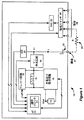
図1は、超小型刺激器10内の回路の例を示している。図示した超小型刺激器は単陽極/多陰極設計であるが、単陽極/単陰極または多陽極/多陰極設計であることもできる。治療のための刺激は、以下のように行われる。陽極電極27は、電流Iを抵抗24(R)、即ちユーザの組織へ供給する。電流の戻り路は、陰極スイッチ30によって選択することができる1つまたはそれ以上の陰極28によってもたらされる。電流Iの大きさは、デジタル・アナログコンバータ、即ちDAC 32によって特定される(DACの回路及び構造は上述した引例に記載されている)。デカップリングキャパシタ22(C)が電流経路内に、通常は陽極電極27の直近に配置されている。公知のように、デカップリングキャパシタ22は、埋込み可能な刺激器デバイスが刺激パルスを供給した後の電荷回復を援助し、また患者の組織24へ電流が直接注入されるのを防ぐことによって付加的な安全性を与える。
FIG. 1 shows an example of a circuit in the
超小型刺激器10は、その種々の論理回路に給電し且つ電極27、28から所望の刺激パルスを供給するのに必要なエネルギを発生させるための電池12を含んでいる。刺激パルスを発生させる場合、一般に電池電圧Vbatからコンプライアンス電圧V+を発生させる必要がある。これは、一般に、所望の治療電流Iを発生させるのに必要な電圧を発生する必要があり、患者の組織の抵抗24が可変であることを考えるとこのような電圧の発生が特に必要だからである。
The
電池電圧Vbatからコンプライアンス電圧V+を発生させるのは、コンプライアンス電圧発生回路18の機能である。コンプライアンス電圧発生回路18は、一般的には電池電圧をより高いコンプライアンス電圧V+までブーストするので、DC−DCコンバータを含んでいる。(回路18は、保証されるべき電池電圧よりも低いコンプライアンス電圧を発生することもできる。)コンプライアンス電圧発生回路18は、超小型刺激器内のコイル15を使用する。以下に説明するように、コイル15は超小型刺激器10内における他の用途をも有している。しかしながら、コンプライアンス電圧発生に関しては、コイル15のインダクタンスをV+発生回路18(通常は、少なくとも1つのキャパシタ及び少なくとも1つのダイオードを含む)と共に使用して所望のコンプライアンス電圧V+を発生する。埋込み可能な医療デバイス内にコンプライアンス電圧を発生させるために、コイル化されたインダクタを使用するV+発生回路の例が、2005年6月16日に公開された米国特許出願第2005/0131496号に記述されているので参照されたい。
It is a function of the compliance
上述したように、コイル15は、超小型刺激器10内の他の目的のために使用することができる。図2に示すように、コイル15は、外部充電器40から電力を無線で受ける手段として、及び外部プログラマ45からデータを無線で受ける手段として使用することもできる。これらの外部デバイスは、典型的には互いに分離されているが、統合することも可能である。公知のように、外部充電器40は、典型的には超小型刺激器内の電池12を再充電するのに使用されるハンドヘルド式である。(他の実施の形態では、外部充電器40は、電池を持たない埋込み型デバイスへエネルギを絶えず供給するのに使用することもできる。)外部プログラマ45も典型的にはハンドヘルド式であり、超小型刺激器10へデータを送るために臨床医または患者が使用する。例えば、外部プログラマ45上のユーザインタフェース(図示してない)を操作することによって、臨床医は患者のために作成された処置プログラムを供給することができる(このプログラムは、患者に供給される刺激パルスの振幅、パルス幅、及び周波数を指定することができる)。
As described above, the
これらの外部デバイスもコイル41、46を含んでいる。これらのコイル41、46は付勢されると磁場を発生し、これらの磁場が超小型刺激器10内のコイル15に電流を誘起させる。充電中には、コイル41からコイル15内に誘起されたエネルギは整流され、充電及び電池保護回路14(図1)を介して電池12へ供給される。回路14は、電池12を、例えば約4.1Vの値まで安全に充電することを可能にする。データテレメトリ中には、外部プログラマ45内のコイル46が、典型的には周波数シフトキーイング(FSK)変調プロトコルを使用して、同じように活性化される。この場合も、得られた磁場がコイル15内に電流を誘起させ、その結果受信された信号がテレメトリ回路16において復調され、伝送されたデータが回復される。データテレメトリは、他の方向へも、即ち、超小型刺激器10がそのステータスを外部プログラマ45へ報告するために、コイル15からコイル46への方向へも行うことができる(因みに、テレメトリ回路16は送信機及び受信機の両方を備えている)。
These external devices also include
以上の説明から、超小型刺激器10内のコイル15が、コンプライアンス電圧の発生、電池の再充電、及びテレメトリに係わっていることが理解されたであろう。超小型刺激器10のハウジング内の空間が制限されており、使用できる離散したコイルの数が制限される傾向にあるので、1つのコイル15を使用して超小型刺激器10内の異なる機能を遂行させることは有利である。従って、一般的には、超小型刺激器10内のマイクロコントローラ20は、種々の機能が競合しないようにコイル15の使用を調停、もしくは時分割する必要がある。例えば、充電中には、テレメトリ回路16及びV+発生回路18はマイクロコントローラ20によって典型的に動作不能にされ、コイル15が超小型刺激器の電池12の再充電の支援だけに使用されるようにする。
From the foregoing, it will be appreciated that the
しかしながら、コンプライアンス電圧発生及びデータテレメトリは、一般に同時に実行させることができるので、マイクロコントローラ20は、所与の時点にこれら2つの機能のどちらがコイル15にアクセスできるかを決定する必要がある。これをより良く理解するために、システム内において如何にデータテレメトリが行われるのかを説明することが有用であろう。外部プログラマ45が超小型刺激器10と通信する必要を生じたものとすれば、外部プログラマ45はハンドシェーキングメッセージを送信し続け、超小型刺激器10からデータ受信の準備が整ったことの応答を待機する。超小型刺激器10自体は、このハンドシェーキングメッセージを定期的に“聴取(listen)”しなければならない。図3に示すように、このような聴取は定期的に、且つ限定された持続時間D(t)の聴取ウィンドウ52中だけにしか行われない。聴取ウィンドウ52中に、テレメトリ回路16が動作可能になり、コイル15がテレメトリのために確保される。聴取ウィンドウ52の持続時間は約20ミリ秒(ms)程度であり、また理想的には、T(t)=100ms程度毎に定期的に発生する。しかしながら、このような周期は、以下に説明するように可変である。
However, since compliance voltage generation and data telemetry can generally be performed simultaneously, the
コンプライアンス電圧の発生は、患者へ治療刺激が与えられている間に行われる。刺激60の処置例が図3に示されている。本質的に、刺激60はパルス62及びパルス間隔期間64の交互シーケンスとして理解できる。パルス62は、所望の治療電流Iが患者へ供給される時間内の点に対応する。これらのパルス62の持続時間D(p)は、典型的に1msを越えることはなく、10マイクロ秒程度の短い持続時間とすることができる。
The generation of the compliance voltage is performed while a therapeutic stimulus is being given to the patient. An example of treatment of the
各パルス62の後のパルス間隔期間64中に、2つの主要イベントが出現する。第1に、次のパルスのためのコンプライアンス電圧が発生される。これは、一般に、パルスを発生させるとコンプライアンス電圧が次のパルスに適切なレベル以下になってしまうので必要である。前述したように、コンプライアンス電圧を発生させるにはV+発生回路18を動作可能にし、コイル15にアクセスする必要がある。第2に、パルス間隔期間64中に、デカップリングキャパシタ22(C)が放電する。上述した11/550,655出願に記載されているように、これは、典型的に陽極及び選択された1つまたは複数の陰極の両者を電池電圧Vbatに結合することによって発生する(この結合は、患者の組織24を通してデカップリングキャパシタ22の両側を短絡する効果を有している)。一般的に、パルス間隔期間64の持続時間D(r)は可変であり、患者に効果的であると選択された刺激パルスの周波数f(s)に依存する。パルス間隔期間の持続時間は、一般にコンプライアンス電圧発生及び出力キャパシタ放電というパルス間に必要なタスクを遂行するための十分な時間を保証する最短時間より短くすることはできない。パルス間隔期間の最短持続時間自体は、刺激タイミング信号60のために選択することができる最大周波数f(s)を制限するが、通常この限界は有用な治療に必要な周波数を越えており、従って、超小型刺激器10の効用を実質的に制限することはない。
Two major events appear during the
前述したように、刺激の供給とテレメトリの聴取を同時に行う必要性があるために、マイクロコントローラ20はコイル15へのアクセスを調停する必要がある。図3は、従来技術ではこれがどのように行われていたかを示している。図示されているのは、テレメトリ聴取(50)と刺激(60)の両者のための理想的なタイミング信号の例である。テレメトリ聴取に関し、聴取ウィンドウ52は理想的に20msの持続時間D(t)にセットされ、100msの周期T(t)で出現していることが分かる。本例の刺激タイミング信号60は、1msのパルス持続時間D(p)、及び55.555Hzの周波数f(s)が選択されている。数学的に言えば、これは18msの合計刺激期間T(s)に対して、パルス間隔期間の持続時間D(r)が17msであることに等しい。
As described above, since it is necessary to simultaneously supply the stimulus and listen to the telemetry, the
これらの数値例をとった場合、マイクロコントローラ20内の調停ロジック21は、テレメトリ聴取タイミング信号(50)及び刺激タイミング信号(60)の両者を理想値から逸脱させる。これは、調停ロジック21が、各刺激サイクル65(パルス62及びパルス間隔期間64からなる)及び各聴取ウィンドウ52を、時間的に重畳することができないブロックとして取扱うからである。従って、マイクロコントローラ20は、調停時に、現在ペンディングの刺激サイクル65が完了してしまうまでは、聴取ウィンドウ52に優先権を与えることはない。例えば、図3において、聴取ウィンドウ52aの理想的タイミングは、刺激サイクル65aの終了と重なっている。従って、調停からもたらされた非理想的テレメトリタイミング信号50’に図示してあるように、聴取ウィンドウ52a’は刺激サイクル65aが閉じるまで、即ち、そのサイクル内のパルス間隔期間64が完了してしまうまで待機させられる。一旦聴取ウィンドウ52a’が出現すると、それはコイル15へのアクセスが邪魔されないことを必要とする。従って、次の刺激サイクル65b’は、聴取ウィンドウ52a’が終了するまで開始することはできない(非理想的刺激タイミング信号60’に示す)。
Taking these numerical examples, the
コイル15へのアクセスに関する競合を軽減させるために使用されている調停スキームの故に、非理想的テレメトリ聴取タイミング信号50’及び非理想的刺激タイミング信号60’がもたらされる。非理想的テレメトリ聴取タイミング信号50’は、聴取ウィンドウ52’間の周期を、理想として望ましい周期(100ms)に比して僅かに長い周期(例えばT(t)=110ms)にする。しかしながら、この周期T(t)の僅かな増加は重大ではなく、または問題にもならない。
Because of the arbitration scheme used to reduce contention for access to
対照的に、得られる非理想的刺激タイミング信号60’は潜在的に問題を含んでいる。図3から明らかなように、調停スキームの結果として、刺激パルス62のパルス間隔が70a、70b等のように引き延ばされてしまう。これらのパルス間隔70aは、患者にとって理想的な措置と考えられる長さ(17ms)よりもかなり長く(37ms)、かなりな頻度で(図3の例においては、例えば、6パルス毎に)発生する。これらのようなパルス間隔の理想からの完全な逸脱は患者に気づかれ易く、従ってひどく嫌がられる。
In contrast, the resulting non-ideal stimulus timing signal 60 'is potentially problematic. As is apparent from FIG. 3, as a result of the arbitration scheme, the pulse interval of the
従って、埋込み可能な刺激器の分野、特に超小型刺激器の分野は、刺激パルスをそれらの理想的タイミングから大きく逸脱させることなく刺激及びテレメトリ聴取を同時に可能にする改良された技術によって利益を得ることになろう。 Thus, the field of implantable stimulators, particularly the microstimulator field, benefits from improved techniques that allow simultaneous stimulation and telemetry listening without greatly deviating the stimulation pulses from their ideal timing. It will be.
超小型刺激器または他の埋込み可能なパルス発生器において、刺激とテレメトリ聴取を同時に可能にする改良された調停スキームが開示される。刺激パルスの供給に続くパルス間隔期間の少なくとも一部分の間に、テレメトリのための聴取ウィンドウを発生させることが許容され、超小型刺激器のコイルへのアクセスが容認される。これは、コイルへのアクセスがパルス間隔期間全体にわたる必要がないから可能なのである。デカップリングキャパシタの放電にはコイルへのアクセスを必要としないので、例えばパルス間隔期間のデカップリングキャパシタが放電されている一部の間に聴取ウィンドウを発生させることができる。これに対して、コンプライアンス電圧を発生させるにはコイルへのアクセスを必要とするので、次の刺激パルスのためにコンプライアンス電圧が発生中である場合には、聴取ウィンドウをパルス間隔期間のその部分の間に発生させることはできない。しかしながら、コンプライアンス電圧の発生は比較的迅速に行われ、パルス間隔期間の僅かな部分だけしか占有しないので、そのパルス間隔期間の部分中に聴取ウィンドウを発生させることができなくても、本技術は大幅に制限されることはない。パルス間隔期間の大部分の間に聴取ウィンドウを発生可能にすることによって、聴取ウィンドウがパルスとパルスの間にもたらすパルス間隔、即ちギャップは小さくなる。その結果、刺激パルスはそれらの理想により近い位置に発生し、患者は、理想的な処置とテレメトリ聴取ウィンドウによってもたらされる処置との差異に気づき難くなる。 An improved arbitration scheme is disclosed that enables simultaneous stimulation and telemetry listening in a microstimulator or other implantable pulse generator. During at least a portion of the pulse interval period following delivery of the stimulation pulse, it is allowed to generate a listening window for telemetry and access to the microstimulator coil is permitted. This is possible because access to the coil does not need to span the entire pulse interval period. Since the discharge of the decoupling capacitor does not require access to the coil, for example, a listening window can be generated during the portion of the decoupling capacitor being discharged during the pulse interval period. On the other hand, generating the compliance voltage requires access to the coil, so if the compliance voltage is being generated for the next stimulation pulse, the listening window is set to that part of the pulse interval period. It cannot be generated in between. However, since the generation of the compliance voltage occurs relatively quickly and occupies only a small part of the pulse interval period, the present technology does not have to generate a listening window during that part of the pulse interval period. There is no significant limitation. By allowing a listening window to be generated during the majority of the pulse interval period, the pulse interval or gap that the listening window provides between pulses is reduced. As a result, the stimulation pulses occur closer to their ideals, making it difficult for the patient to notice the difference between the ideal treatment and the treatment provided by the telemetry listening window.
本発明による技術の中核は、超小型刺激器10内のコイル15へのアクセスが、パルス間隔期間64の全体である必要がないことを認識することである。前述したように、パルス間隔期間64中には2つの主要イベント、即ち、次の刺激パルス62に給電するための適切な電圧を形成するコンプライアンス電圧発生と、デカップリングキャパシタ22(C)の放電とが発生する。これら2つのパルス間に発生する機能のタイミングを示している図4Aには、所与の患者のための理想的な刺激タイミング信号60も示されている。図示のように、コンプライアンス電圧発生及びデカップリングキャパシタ放電の両者は、パルス間隔期間64中に並行して出現し、これらの両機能は本質的に先行刺激パルス62の発生直後に始まる。(実際には、刺激パルス62の終わりと回復期間64機能の間に他の機能が超小型刺激器10内で発生しているであろうが、これらは今検討している時間スケールに比較して重要ではないか、及び/または無視することができる。)
The core of the technology according to the present invention is to recognize that access to the
発明者等は、コンプライアンス電圧の発生はパルス間隔期間64中に比較的迅速に行われ、一方デカップリングキャパシタ22の放電は比較的ゆっくりと行われることに注目した。コンプライアンス電圧発生の持続時間D(g)は、典型的に1ミリ秒未満である。これに対して、デカップリングキャパシタ22を放電させるのに必要な持続時間D(c)は、10ミリ秒まで、またはそれ以上を要する。大事なのは、デカップリングキャパシタ放電の持続時間D(c)は刺激パルスの幅と振幅との積に比例し、従って可変であるが、それでも典型的にはコンプライアンス電圧発生に必要な持続時間D(g)よりは少なくとも5乃至10倍は長いと言うことである。
The inventors have noted that compliance voltage generation occurs relatively quickly during the
これらの持続時間D(g)とD(c)との差は、特にコイル15に与えるインパクトを考えた場合、聴取ウィンドウ52によって刺激パルス62が休止させられる問題にとって重大である。デカップリングキャパシタの放電は、コイル15へのアクセスを必要としない。従って、テレメトリ聴取ウィンドウ52(テレメトリ聴取は、コイルへのアクセスを必要とする)を、デカップリングキャパシタの放電と同時に発生させるように調停することができる。しかしながら、コンプライアンス電圧発生はコイルへのアクセスを必要とするので、テレメトリ聴取ウィンドウ52をコンプライアンス電圧発生と同時に発生させるように調停することはできない。
The difference between these durations D (g) and D (c) is significant for the problem that the
本発明による技術の一実施の形態による効果は、マイクロコントローラ20が、コンプライアンス電圧発生が完了した後に(即ち、持続時間D(g)の後に)、しかしデカップリングキャパシタ22の放電と同時に、聴取ウィンドウ52を発生させ得ることである。これは、図4Aの改良されたテレメトリ聴取タイミング信号50’に示されている。図示のように、聴取ウィンドウ52’は、それがコンプライアンス電圧発生D(g)の後に発生するように、その理想的位置(50)からパルス間隔期間64の一部へ移動している。これにより、上述したように、聴取ウィンドウが完了した後に次の刺激パルス62b’を発生させることができる。図4Aは、聴取ウィンドウ52’が早い時点へ移動することを示しているが、本発明の技術による調停では、聴取ウィンドウ52’が次のパルス62bのコンプライアンス電圧発生の後に、即ち、パルス62bと62cとの間に出現するように聴取ウィンドウ52’を遅い時間に移動させることもできる。大事なのは、聴取ウィンドウの周期T(t)の変化が問題視する程大きい量ではないから、聴取ウィンドウ52’がその理想的位置(50)から時間的に早め、または遅めの何れに移動したのかは、本技術にとって重要ではないことである。
The effect of one embodiment of the technique according to the present invention is that the
パルス間隔期間64の“コイル不使用”部分に聴取ウィンドウ52を侵入又は発生させることを許容することによって、図3に示す従来技術と比較して、刺激パルス62間の聴取ウィンドウのギャップ70が大幅に短縮されていることが分かる。この比較は、図4Bに最良に示されている。図4Bは、従来技術(図3)、及び本発明による技術(図4A)を使用して得られる非理想的刺激タイミング信号60’を示しており、刺激パルス62に対するそれらの関係を理解するために聴取ウィンドウ52または52’も点在させてある。上例に基づいて説明を続けると、17msの理想的パルス間隔期間D(r)と比較した時に、従来技術がD(r)+D(t)=37msのギャップ70であったのに対して、本技術はD(g)+D(t)=21msのギャップ70に留まっている。このように、本技術を使用して得られる刺激タイミング信号60’は理想60に極めて近づいており、従って、患者に気づかれ難くなっている。
By allowing the listening
更に、もし聴取ウィンドウ52の持続時間D(t)が所与の応用におけるパルス間隔期間64の持続時間D(r)に比して相対的に短ければ、本技術を使用することによって過大なギャップ70を完全に排除することができ、その結果得られる刺激タイミング信号60’は完全に理想的になる。これは、コンプライアンス電圧発生の持続時間D(g)と聴取ウィンドウの持続時間D(t)の和が、必要なパルス間隔期間の持続時間D(r)よりも短いか、または等しければ(即ち、D(g)+D(t)≦D(r)の場合に)得られる。
Furthermore, if the duration D (t) of the listening
本発明による技術を実現するのは比較的簡単であり、且つ標準の超小型刺激器10のソフトウェアの変更(ハードウェア変更ではない)を、特に、調停ロジック21のソフトウェア変更を必要とするだけである。例えば、再度図1を参照し、V+発生回路18が発生するコンプライアンス電圧V+の大きさは、A/Dコンバータ31(マイクロコントローラと共に統合することができる)を介してマイクロコントローラ20によって監視される。このフィードバック経路は、典型的には他の理由から(例えば、過大な、安全でないコンプライアンス電圧の発生を監視し、保護するために)既に存在しているので、調停ロジック21の適切なソフトウェア変更によって、聴取ウィンドウ調停中にそれを使用するように活用することができる。詳述すれば、調停ロジック21は、超小型刺激器10が現在パルス間隔期間64内にあるのか否かを判断し、もし期間64内にあれば、コンプライアンス電圧V+を適切なレベルまで発生したか否か、例えばD(g)が経過したか否か、またはV+電圧がある大きさに到達したか否かを判断する。もし否でなければ、上述した技術に従って適切であるとしてテレメトリ回路16を動作可能にすることによって、調停ロジック21が聴取ウィンドウ52を発生させるのを許容することができる。
Implementing the technique according to the present invention is relatively simple and requires only software changes (not hardware changes) of the standard
以上、テレメトリ聴取ウィンドウを供給するためのタイミングの改良に関して説明したが、開示した技術はそのように限定されるものではないことを理解されたい。例えば、開示した技術は、たとえウィンドウの目的が外部デバイスからのテレメトリの聴取ではなくても、何等かの種類の定期的に発生されるテレメトリウィンドウのタイミングを改善するために使用することができる。例えば、時間調停されたテレメトリウィンドウを使用して、刺激が行われている間であっても、データを定期的に外部デバイスから受信し、またはデータを外部デバイスへ定期的に送信することができる。以上のように、開示した技術を使用すれば、刺激パルスを患者に供給しながら、プログラミングデータを複数のテレメトリウィンドウにわたって徐々に受信することができる。もしくは、超小型刺激器は、テレメトリウィンドウを使用してそのステータスに関する情報を外部デバイスに定期的に供給することができ、この場合も、刺激パルスが患者に供給される。 Although the foregoing has been described with respect to improved timing for providing a telemetry listening window, it should be understood that the disclosed technique is not so limited. For example, the disclosed technique can be used to improve the timing of any kind of regularly generated telemetry window, even if the purpose of the window is not to listen to telemetry from an external device. For example, a time-adjusted telemetry window can be used to periodically receive data from or send data to an external device even while stimulation is taking place . As described above, using the disclosed technique, it is possible to gradually receive programming data over a plurality of telemetry windows while supplying stimulation pulses to a patient. Alternatively, the microstimulator can periodically provide information about its status to an external device using a telemetry window, and again, stimulation pulses are delivered to the patient.
以上、本発明を特定の実施の形態及びそれらの応用によって説明したが、当業者ならば、特許請求の範囲に記載されている本発明の文字通りの、及び等価な範囲から逸脱することなく多くの変更及び変化が可能であろう。 While the invention has been described in terms of specific embodiments and applications thereof, those skilled in the art will recognize many variations without departing from the literal and equivalent scope of the invention as set forth in the claims. Changes and changes may be possible.
10 超小型刺激器
12 電池
14 充電及び電池保護回路
15 コイル
16 テレメトリ回路
18 コンプライアンス電圧発生回路
20 マイクロコントローラ
21 調停ロジック
22 デカップリングキャパシタ
40 外部充電器
45 外部プログラマ
50 テレメトリ聴取タイミング信号
52 テレメトリ聴取ウィンドウ
60 刺激タイミング信号
62 刺激パルス
64 パルス間隔期間
65 刺激サイクル
70 ギャップ
D(t) 聴取ウィンドウの持続時間
D(p) パルス持続時間
D(r) パルス間隔期間の持続時間
D(c) 放電の持続時間
D(g) コンプライアンス電圧発生の持続時間
T(s) 刺激期間
f(s) 刺激パルスの周波数
10
Claims (7)
1つのコイルと、
患者の組織へ刺激サイクル毎に刺激パルスを供給するための少なくとも1つの電極と、
前記コイルを用いてテレメトリウィンドウ中に外部デバイスと通信するためのテレメトリ回路と、
前記コイルを用いて電池電圧から上記少なくとも1つの電極における第1の電圧を発生するためのコンプライアンス電圧発生回路と、
調停ロジックと、を含み、
前記刺激サイクルは、前記刺激パルスとパルス間隔期間からなり、
上記調停ロジックは、前記テレメトリウィンドウ中に、上記テレメトリ回路が外部デバイスと通信できるようにするために、上記コイルへアクセスすることを容認し、上記調停ロジックは、上記刺激サイクルのパルス間隔期間の少なくとも一部分に前記テレメトリウィンドウが重なるが、上記刺激サイクルのパルス間隔期間中の上記コンプライアンス電圧発生回路が上記コイルへアクセスしている部分中には前記テレメトリウィンドウが重ならないように、連続する2つの刺激パルス間に前記テレメトリウィンドウを挿入し、このテレメトリウィンドウの後に前記連続する刺激パルスのうちの後者の刺激パルスを発生させる、ことを特徴とする埋込み可能な刺激デバイス。An implantable stimulation device comprising:
One coil,
At least one electrode for delivering stimulation pulses to the patient's tissue for each stimulation cycle ;
A telemetry circuit for communicating with an external device during a telemetry window using the coil ;
A compliance voltage generating circuit for generating a first voltage at the at least one electrode from a battery voltage using the coil ;
Arbitration logic, and
The stimulation cycle consists of the stimulation pulse and a pulse interval period,
The arbitration logic allows access to the coil during the telemetry window to allow the telemetry circuit to communicate with an external device, and the arbitration logic reduces the pulse interval period of the stimulation cycle. At least a portion of the telemetry window overlaps, but two successive two so that the telemetry window does not overlap during the pulse interval of the stimulation cycle while the compliance voltage generation circuit is accessing the coil. An implantable stimulation device , wherein the telemetry window is inserted between stimulation pulses, and the latter stimulation pulse of the successive stimulation pulses is generated after the telemetry window .
Applications Claiming Priority (3)
| Application Number | Priority Date | Filing Date | Title |
|---|---|---|---|
| US11/776,170 | 2007-07-11 | ||
| US11/776,170 US8131377B2 (en) | 2007-07-11 | 2007-07-11 | Telemetry listening window management for an implantable medical device |
| PCT/US2008/068079 WO2009009290A1 (en) | 2007-07-11 | 2008-06-25 | Telemetry listening window management for an implantable medical device |
Publications (3)
| Publication Number | Publication Date |
|---|---|
| JP2010532700A JP2010532700A (en) | 2010-10-14 |
| JP2010532700A5 JP2010532700A5 (en) | 2012-01-19 |
| JP5175345B2 true JP5175345B2 (en) | 2013-04-03 |
Family
ID=39732811
Family Applications (1)
| Application Number | Title | Priority Date | Filing Date |
|---|---|---|---|
| JP2010516122A Expired - Fee Related JP5175345B2 (en) | 2007-07-11 | 2008-06-25 | Telemetry listening window management for implantable medical devices |
Country Status (6)
| Country | Link |
|---|---|
| US (1) | US8131377B2 (en) |
| EP (1) | EP2167189B1 (en) |
| JP (1) | JP5175345B2 (en) |
| CA (1) | CA2687227C (en) |
| ES (1) | ES2594202T3 (en) |
| WO (1) | WO2009009290A1 (en) |
Families Citing this family (32)
| Publication number | Priority date | Publication date | Assignee | Title |
|---|---|---|---|---|
| US8335569B2 (en) | 2009-02-10 | 2012-12-18 | Boston Scientific Neuromodulation Corporation | External device for communicating with an implantable medical device having data telemetry and charging integrated in a single housing |
| US9233254B2 (en) | 2009-02-17 | 2016-01-12 | Boston Scientific Neuromodulation Corporation | Selectable boost converter and charge pump for compliance voltage generation in an implantable stimulator device |
| US8744592B2 (en) | 2009-10-08 | 2014-06-03 | Boston Scientific Neuromodulation Corporation | Efficient external charger for an implantable medical device optimized for fast charging and constrained by an implant power dissipation limit |
| US9042995B2 (en) * | 2010-02-03 | 2015-05-26 | Medtronic, Inc. | Implantable medical devices and systems having power management for recharge sessions |
| WO2011097289A1 (en) | 2010-02-03 | 2011-08-11 | Medtronic, Inc. | Implantable medical devices and systems having dual frequency inductive telemetry and recharge |
| US8788045B2 (en) | 2010-06-08 | 2014-07-22 | Bluewind Medical Ltd. | Tibial nerve stimulation |
| US9186504B2 (en) | 2010-11-15 | 2015-11-17 | Rainbow Medical Ltd | Sleep apnea treatment |
| US9457186B2 (en) | 2010-11-15 | 2016-10-04 | Bluewind Medical Ltd. | Bilateral feedback |
| US9136728B2 (en) | 2011-04-28 | 2015-09-15 | Medtronic, Inc. | Implantable medical devices and systems having inductive telemetry and recharge on a single coil |
| US20130123881A1 (en) * | 2011-11-11 | 2013-05-16 | Boston Scientific Neuromodulation Corporation | External Charger for an Implantable Medical Device System Having a Coil for Communication and Charging |
| US20150018728A1 (en) | 2012-01-26 | 2015-01-15 | Bluewind Medical Ltd. | Wireless neurostimulators |
| AU2013252839B2 (en) | 2012-04-27 | 2015-09-17 | Boston Scientific Neuromodulation Corporation | Timing channel circuitry for creating pulses in an implantable stimulator device |
| US9174051B2 (en) * | 2012-04-29 | 2015-11-03 | Boston Scientific Neuromodulation Corporation | Real time compliance voltage generation for an implantable stimulator |
| US9314632B2 (en) | 2012-05-17 | 2016-04-19 | Boston Scientific Neuromodulation Corporation | Pulse-by-pulse compliance voltage generation for an implantable stimulator |
| WO2014087337A1 (en) | 2012-12-06 | 2014-06-12 | Bluewind Medical Ltd. | Delivery of implantable neurostimulators |
| US9795788B2 (en) * | 2013-05-30 | 2017-10-24 | Pacesetter, Inc. | Implantable medical devices, and methods of use therewith, that use a same coil for receiving both communication and power signals |
| AU2014307084B2 (en) * | 2013-08-14 | 2017-05-18 | Boston Scientific Neuromodulation Corporation | Power architecture for an implantable medical device having a non-rechargeable battery |
| EP3046621B1 (en) | 2013-09-16 | 2021-05-26 | The Board of Trustees of the Leland Stanford Junior University | Multi-element coupler for generation of electromagnetic energy |
| US20160336813A1 (en) | 2015-05-15 | 2016-11-17 | NeuSpera Medical Inc. | Midfield coupler |
| EP3753517B1 (en) | 2014-05-18 | 2022-05-11 | Neuspera Medical Inc. | Midfield coupler |
| US9764146B2 (en) | 2015-01-21 | 2017-09-19 | Bluewind Medical Ltd. | Extracorporeal implant controllers |
| US10004896B2 (en) | 2015-01-21 | 2018-06-26 | Bluewind Medical Ltd. | Anchors and implant devices |
| US9597521B2 (en) | 2015-01-21 | 2017-03-21 | Bluewind Medical Ltd. | Transmitting coils for neurostimulation |
| US9782589B2 (en) | 2015-06-10 | 2017-10-10 | Bluewind Medical Ltd. | Implantable electrostimulator for improving blood flow |
| US10105540B2 (en) | 2015-11-09 | 2018-10-23 | Bluewind Medical Ltd. | Optimization of application of current |
| US9713707B2 (en) | 2015-11-12 | 2017-07-25 | Bluewind Medical Ltd. | Inhibition of implant migration |
| WO2018071906A1 (en) * | 2016-10-16 | 2018-04-19 | Stimaire, Inc. | Wireless neural stimulator with injectable |
| US10124178B2 (en) | 2016-11-23 | 2018-11-13 | Bluewind Medical Ltd. | Implant and delivery tool therefor |
| US20180353764A1 (en) | 2017-06-13 | 2018-12-13 | Bluewind Medical Ltd. | Antenna configuration |
| WO2022072973A1 (en) | 2020-09-30 | 2022-04-07 | Boston Scientific Neuromodulation Corporation | Pairing of external communication devices with an implantable medical device via a patient remote controller |
| EP4192575A1 (en) | 2020-09-30 | 2023-06-14 | Boston Scientific Neuromodulation Corporation | Adjustment of advertising interval in communications between an implantable medical device and an external device |
| US11400299B1 (en) | 2021-09-14 | 2022-08-02 | Rainbow Medical Ltd. | Flexible antenna for stimulator |
Family Cites Families (27)
| Publication number | Priority date | Publication date | Assignee | Title |
|---|---|---|---|---|
| US5088488A (en) * | 1989-12-22 | 1992-02-18 | Medtronic, Inc. | Method and apparatus for implementing histogram storage and trend analysis in a medical stimulator |
| US5314458A (en) * | 1990-06-01 | 1994-05-24 | University Of Michigan | Single channel microstimulator |
| US5201865A (en) * | 1991-10-28 | 1993-04-13 | Medtronic, Inc. | Medical lead impedance measurement system |
| US5309919A (en) * | 1992-03-02 | 1994-05-10 | Siemens Pacesetter, Inc. | Method and system for recording, reporting, and displaying the distribution of pacing events over time and for using same to optimize programming |
| US5507786A (en) * | 1994-04-14 | 1996-04-16 | Pacesetter, Inc. | System and method for measuring and storing parametric data pertaining to operating characteristics of an implantable medical device |
| US5766232A (en) * | 1996-05-10 | 1998-06-16 | Medtronic, Inc. | Method and apparatus for altering the Q of an implantable medical device telemetry antenna |
| US5733312A (en) * | 1997-01-17 | 1998-03-31 | Pacesetter, Inc. | System and method for modulating the output of an implantable medical device in response to circadian variations |
| US5978713A (en) * | 1998-02-06 | 1999-11-02 | Intermedics Inc. | Implantable device with digital waveform telemetry |
| US9113801B2 (en) * | 1998-08-05 | 2015-08-25 | Cyberonics, Inc. | Methods and systems for continuous EEG monitoring |
| US6516227B1 (en) * | 1999-07-27 | 2003-02-04 | Advanced Bionics Corporation | Rechargeable spinal cord stimulator system |
| US6553263B1 (en) * | 1999-07-30 | 2003-04-22 | Advanced Bionics Corporation | Implantable pulse generators using rechargeable zero-volt technology lithium-ion batteries |
| US6631296B1 (en) * | 2000-03-17 | 2003-10-07 | Advanced Bionics Corporation | Voltage converter for implantable microstimulator using RF-powering coil |
| US6535766B1 (en) * | 2000-08-26 | 2003-03-18 | Medtronic, Inc. | Implanted medical device telemetry using integrated microelectromechanical filtering |
| US6868288B2 (en) * | 2000-08-26 | 2005-03-15 | Medtronic, Inc. | Implanted medical device telemetry using integrated thin film bulk acoustic resonator filtering |
| US6556871B2 (en) * | 2001-01-04 | 2003-04-29 | Cardiac Pacemakers, Inc. | System and method for receiving telemetry data from an implantable medical device |
| US20040015205A1 (en) * | 2002-06-20 | 2004-01-22 | Whitehurst Todd K. | Implantable microstimulators with programmable multielectrode configuration and uses thereof |
| US7177698B2 (en) * | 2002-06-28 | 2007-02-13 | Advanced Bionics Corporation | Telemetry system for use with microstimulator |
| US7428438B2 (en) * | 2002-06-28 | 2008-09-23 | Boston Scientific Neuromodulation Corporation | Systems and methods for providing power to a battery in an implantable stimulator |
| US7813809B2 (en) * | 2004-06-10 | 2010-10-12 | Medtronic, Inc. | Implantable pulse generator for providing functional and/or therapeutic stimulation of muscles and/or nerves and/or central nervous system tissue |
| US20050075696A1 (en) * | 2003-10-02 | 2005-04-07 | Medtronic, Inc. | Inductively rechargeable external energy source, charger, system and method for a transcutaneous inductive charger for an implantable medical device |
| ATE523221T1 (en) * | 2004-06-10 | 2011-09-15 | Medtronic Urinary Solutions Inc | SYSTEMS AND METHODS FOR THE BILATERAL STIMULATION OF LEFT AND RIGHT BRANCHES OF THE DORSAL GENITAL NERVES FOR THE TREATMENT OF FUNCTIONAL DISORDERS SUCH AS URINARY INCONTINENCE |
| US9308382B2 (en) * | 2004-06-10 | 2016-04-12 | Medtronic Urinary Solutions, Inc. | Implantable pulse generator systems and methods for providing functional and/or therapeutic stimulation of muscles and/or nerves and/or central nervous system tissue |
| US7702385B2 (en) * | 2005-11-16 | 2010-04-20 | Boston Scientific Neuromodulation Corporation | Electrode contact configurations for an implantable stimulator |
| US7957805B2 (en) * | 2005-06-01 | 2011-06-07 | Boston Scientific Neuromodulation Corporation | Implantable microstimulator with external electrodes disposed on a film substrate and methods of manufacture and use |
| EP2471452B1 (en) | 2005-10-14 | 2014-12-10 | Pacesetter, Inc. | Cardiac pacing system and method of conveying information therein |
| US9480846B2 (en) * | 2006-05-17 | 2016-11-01 | Medtronic Urinary Solutions, Inc. | Systems and methods for patient control of stimulation systems |
| WO2007136657A2 (en) | 2006-05-17 | 2007-11-29 | Ndi Medical, Inc. | Implantable pulse generator systems and methods for providing stimulation |
-
2007
- 2007-07-11 US US11/776,170 patent/US8131377B2/en not_active Expired - Fee Related
-
2008
- 2008-06-25 ES ES08771858.1T patent/ES2594202T3/en active Active
- 2008-06-25 EP EP08771858.1A patent/EP2167189B1/en not_active Not-in-force
- 2008-06-25 WO PCT/US2008/068079 patent/WO2009009290A1/en active Application Filing
- 2008-06-25 JP JP2010516122A patent/JP5175345B2/en not_active Expired - Fee Related
- 2008-06-25 CA CA2687227A patent/CA2687227C/en not_active Expired - Fee Related
Also Published As
| Publication number | Publication date |
|---|---|
| JP2010532700A (en) | 2010-10-14 |
| US8131377B2 (en) | 2012-03-06 |
| EP2167189A1 (en) | 2010-03-31 |
| CA2687227A1 (en) | 2009-01-15 |
| ES2594202T3 (en) | 2016-12-16 |
| CA2687227C (en) | 2014-04-15 |
| WO2009009290A1 (en) | 2009-01-15 |
| US20090018618A1 (en) | 2009-01-15 |
| EP2167189B1 (en) | 2016-07-20 |
Similar Documents
| Publication | Publication Date | Title |
|---|---|---|
| JP5175345B2 (en) | Telemetry listening window management for implantable medical devices | |
| US10518089B2 (en) | Reversing recruitment order by anode intensification | |
| US20170281948A1 (en) | Neuromodulation system and method for providing multiple modulation patterns in a single channel | |
| US9981134B2 (en) | Multi-channel neuromodulation system having frequency modulation stimulation | |
| US9339655B2 (en) | System and method for compounding low-frequency sources for high-frequency neuromodulation | |
| US9463323B2 (en) | Spatially selective nerve stimulation in high-frequency nerve conduction block and recruitment | |
| US20170326365A1 (en) | Methods to avoid frequency locking in a multi-channel neurostimulation system using pulse shifting | |
| US8812115B2 (en) | System and method for reducing excitability of dorsal root fiber by introducing stochastic background noise | |
| US8543200B2 (en) | Methods to avoid frequency locking in a multi-channel neurostimulation system using pulse placement | |
| US9782592B2 (en) | Energy efficient high frequency nerve blocking technique | |
| EP2328652A1 (en) | System and method for increasing relative intensity between cathodes and anodes of neurostimulation system | |
| JP2013542836A (en) | Notification of start status of implantable nerve stimulator |
Legal Events
| Date | Code | Title | Description |
|---|---|---|---|
| A521 | Request for written amendment filed |
Free format text: JAPANESE INTERMEDIATE CODE: A523 Effective date: 20111124 |
|
| A131 | Notification of reasons for refusal |
Free format text: JAPANESE INTERMEDIATE CODE: A131 Effective date: 20120213 |
|
| A521 | Request for written amendment filed |
Free format text: JAPANESE INTERMEDIATE CODE: A523 Effective date: 20120514 |
|
| TRDD | Decision of grant or rejection written | ||
| A01 | Written decision to grant a patent or to grant a registration (utility model) |
Free format text: JAPANESE INTERMEDIATE CODE: A01 Effective date: 20121210 |
|
| A61 | First payment of annual fees (during grant procedure) |
Free format text: JAPANESE INTERMEDIATE CODE: A61 Effective date: 20130104 |
|
| R150 | Certificate of patent or registration of utility model |
Ref document number: 5175345 Country of ref document: JP Free format text: JAPANESE INTERMEDIATE CODE: R150 |
|
| R250 | Receipt of annual fees |
Free format text: JAPANESE INTERMEDIATE CODE: R250 |
|
| R250 | Receipt of annual fees |
Free format text: JAPANESE INTERMEDIATE CODE: R250 |
|
| R250 | Receipt of annual fees |
Free format text: JAPANESE INTERMEDIATE CODE: R250 |
|
| LAPS | Cancellation because of no payment of annual fees |