JP5165169B2 - Liquid crystal display - Google Patents
Liquid crystal display Download PDFInfo
- Publication number
- JP5165169B2 JP5165169B2 JP2001063494A JP2001063494A JP5165169B2 JP 5165169 B2 JP5165169 B2 JP 5165169B2 JP 2001063494 A JP2001063494 A JP 2001063494A JP 2001063494 A JP2001063494 A JP 2001063494A JP 5165169 B2 JP5165169 B2 JP 5165169B2
- Authority
- JP
- Japan
- Prior art keywords
- signal line
- liquid crystal
- pixel
- electrode
- pixel electrode
- Prior art date
- Legal status (The legal status is an assumption and is not a legal conclusion. Google has not performed a legal analysis and makes no representation as to the accuracy of the status listed.)
- Expired - Fee Related
Links
Images


Classifications
-
- G—PHYSICS
- G02—OPTICS
- G02F—OPTICAL DEVICES OR ARRANGEMENTS FOR THE CONTROL OF LIGHT BY MODIFICATION OF THE OPTICAL PROPERTIES OF THE MEDIA OF THE ELEMENTS INVOLVED THEREIN; NON-LINEAR OPTICS; FREQUENCY-CHANGING OF LIGHT; OPTICAL LOGIC ELEMENTS; OPTICAL ANALOGUE/DIGITAL CONVERTERS
- G02F1/00—Devices or arrangements for the control of the intensity, colour, phase, polarisation or direction of light arriving from an independent light source, e.g. switching, gating or modulating; Non-linear optics
- G02F1/01—Devices or arrangements for the control of the intensity, colour, phase, polarisation or direction of light arriving from an independent light source, e.g. switching, gating or modulating; Non-linear optics for the control of the intensity, phase, polarisation or colour
- G02F1/13—Devices or arrangements for the control of the intensity, colour, phase, polarisation or direction of light arriving from an independent light source, e.g. switching, gating or modulating; Non-linear optics for the control of the intensity, phase, polarisation or colour based on liquid crystals, e.g. single liquid crystal display cells
- G02F1/133—Constructional arrangements; Operation of liquid crystal cells; Circuit arrangements
- G02F1/1333—Constructional arrangements; Manufacturing methods
- G02F1/1343—Electrodes
-
- G—PHYSICS
- G02—OPTICS
- G02F—OPTICAL DEVICES OR ARRANGEMENTS FOR THE CONTROL OF LIGHT BY MODIFICATION OF THE OPTICAL PROPERTIES OF THE MEDIA OF THE ELEMENTS INVOLVED THEREIN; NON-LINEAR OPTICS; FREQUENCY-CHANGING OF LIGHT; OPTICAL LOGIC ELEMENTS; OPTICAL ANALOGUE/DIGITAL CONVERTERS
- G02F1/00—Devices or arrangements for the control of the intensity, colour, phase, polarisation or direction of light arriving from an independent light source, e.g. switching, gating or modulating; Non-linear optics
- G02F1/01—Devices or arrangements for the control of the intensity, colour, phase, polarisation or direction of light arriving from an independent light source, e.g. switching, gating or modulating; Non-linear optics for the control of the intensity, phase, polarisation or colour
- G02F1/13—Devices or arrangements for the control of the intensity, colour, phase, polarisation or direction of light arriving from an independent light source, e.g. switching, gating or modulating; Non-linear optics for the control of the intensity, phase, polarisation or colour based on liquid crystals, e.g. single liquid crystal display cells
- G02F1/133—Constructional arrangements; Operation of liquid crystal cells; Circuit arrangements
- G02F1/1333—Constructional arrangements; Manufacturing methods
- G02F1/1335—Structural association of cells with optical devices, e.g. polarisers or reflectors
- G02F1/133553—Reflecting elements
-
- G—PHYSICS
- G02—OPTICS
- G02F—OPTICAL DEVICES OR ARRANGEMENTS FOR THE CONTROL OF LIGHT BY MODIFICATION OF THE OPTICAL PROPERTIES OF THE MEDIA OF THE ELEMENTS INVOLVED THEREIN; NON-LINEAR OPTICS; FREQUENCY-CHANGING OF LIGHT; OPTICAL LOGIC ELEMENTS; OPTICAL ANALOGUE/DIGITAL CONVERTERS
- G02F1/00—Devices or arrangements for the control of the intensity, colour, phase, polarisation or direction of light arriving from an independent light source, e.g. switching, gating or modulating; Non-linear optics
- G02F1/01—Devices or arrangements for the control of the intensity, colour, phase, polarisation or direction of light arriving from an independent light source, e.g. switching, gating or modulating; Non-linear optics for the control of the intensity, phase, polarisation or colour
- G02F1/13—Devices or arrangements for the control of the intensity, colour, phase, polarisation or direction of light arriving from an independent light source, e.g. switching, gating or modulating; Non-linear optics for the control of the intensity, phase, polarisation or colour based on liquid crystals, e.g. single liquid crystal display cells
- G02F1/133—Constructional arrangements; Operation of liquid crystal cells; Circuit arrangements
- G02F1/1333—Constructional arrangements; Manufacturing methods
- G02F1/1343—Electrodes
- G02F1/134309—Electrodes characterised by their geometrical arrangement
- G02F1/134363—Electrodes characterised by their geometrical arrangement for applying an electric field parallel to the substrate, i.e. in-plane switching [IPS]
Description
【0001】
【発明の属する技術分野】
本発明は液晶表示装置に係り、特に、反射型と称される液晶表示装置に関する。
【0002】
【従来の技術】
液晶表示装置は液晶を介して対向配置される一対の基板を外囲器とし、該液晶の広がり方向に多数の画素からなる液晶表示部を備えて構成される。
【0003】
各画素の液晶はそれに印加される電界の強さによって光の透過率が制御されるようになっている。
【0004】
また、反射型と称される液晶表示装置は、前記各基板のうち一方の基板の液晶側の面であって、少なくも画素領域の全部に(あるいは一部に:この場合一部反射型と称される場合がある)光の反射効率の良好な反射膜を備えて構成される。この場合、この反射膜は、液晶に電界を印加させる際の一方の電極を構成することが通常である。
【0005】
液晶表示装置の液晶表示部へ外来光が入射し、各画素の液晶を通して該反射膜で反射される光を観察することによって、該液晶表示部における映像を認識できる。
【0006】
【発明が解決しようとする課題】
しかしながら、このように構成される反射型の液晶表示装置において、前記反射膜をその表面に凹凸が形成されるようにして構成し、これにより反射光の照射方向をある程度散乱させるようにすることが望ましい。
【0007】
表面が平坦な反射膜の場合、観察者が液晶表示部を観察した際に観察者の顔あるいはその背景等が鮮明に映ってしまう場合があるからである。
【0008】
しかしながら、反射膜を上記のように加工することは製造工程の増大等を招くことになり、他の工夫がなされるに到った。
【0009】
本発明は、このような事情に基づいてなされたものであり、その目的は特別な構成を施すことなく反射型として信頼性の優れた液晶表示装置を提供することにある。
【0010】
【課題を解決するための手段】
本発明において開示される発明のうち、代表的なものの概要を簡単に説明すれば、以下のとおりである。
【0011】
本発明による液晶表示装置は、たとえば、液晶を介して対向配置される各基板のうち一方の基板の液晶側の各画素領域に、前記一方の基板側から、一方の電極、絶縁層、他方の電極が積層されて形成され、前記一方の電極は反射膜を兼ねる構成として形成され、他方の電極は前記一方の電極の形成領域内で一方向に延在し該一方向と交差する方向に並設された複数の電極から形成されていることを特徴とするものである。
【0012】
このように構成された液晶表示装置は、反射膜を兼ねる一方の電極の絶縁膜を介した上層は、他の電極によって凹凸が形成された面として形成されることになる。
【0013】
このため、外来光が液晶を介して反射膜に入射し、該反射膜で反射された光が前記凹凸によって散乱されるようになる。
【0014】
したがって、特別な構成を施すことなく反射型として信頼性の優れた液晶表示装置を得ることができる。
【0015】
【発明の実施の形態】
以下、本発明による液晶表示装置の実施例を図面を用いて説明をする。
【0016】
実施例1.
《等価回路》
図2は本発明による液晶表示装置の等価回路を示す図である。同図は等価回路であるが、実際の幾何学配置に対応した図となっている。
【0017】
同図において、透明基板SUB1があり、この透明基板SUB1は液晶を介して他の透明基板SUB2と対向して配置されている。
【0018】
前記透明基板SUB1の液晶側の面には、図中x方向に延在しy方向に並設されるゲート信号線GLと、このゲート信号線GLと絶縁されてy方向に延在しx方向に並設されるドレイン信号線DLとが形成され、これら各信号線で囲まれる矩形状の領域が画素領域となり、これら各画素領域の集合によって表示部ARを構成するようになっている。
【0019】
また、各ゲート信号線GLの間には該ゲート信号線GLと平行に配置された対向電圧信号線CLが形成されている。これら各対向電圧信号線CLは後述する映像信号に対して基準となる信号(電圧)が供給されるようになっており、各画素領域において後述する対向電極CTと接続されるようになっている。
【0020】
各画素領域には、一方のゲート信号線GLからの走査信号(電圧)の供給によって駆動される薄膜トランジスタTFTと、この薄膜トランジスタTFTを介して一方のドレイン信号線DLからの映像信号(電圧)が供給される画素電極PIXが形成されている。
【0021】
また、画素電極PIXと対向電圧信号線CLとの間には容量素子Cstgが形成され、この容量素子Cstgによって、前記薄膜トランジスタTFTがオフした際に、画素電極PIXに供給された映像信号を長く蓄積させるようになっている。
【0022】
各画素領域における画素電極PIXは、この画素電極PXと隣接する対向電極CTとの間に透明基板SUB1に対してほぼ平行な成分を有する電界を発生せしめるようになっており、これにより対応する画素領域の液晶の光透過率を制御するようになっている。
【0023】
各ゲート信号線GLの一端は透明基板の一辺側(図中左側)に延在され、その延在部は該透明基板SUB1に搭載される垂直走査回路からなる半導体集積回路GDRCのバンプと接続される端子部GTMが形成され、また、各ドレイン信号線DLの一端も透明基板SUB1の一辺側(図中上側)に延在され、その延在部は該透明基板SUB1に搭載される映像信号駆動回路からなる半導体集積回路DDRCのバンプと接続される端子部DTMが形成されている。
【0024】
半導体集積回路GDRC、DDRCはそれぞれ、それ自体が透明基板SUB1上に完全に搭載されたもので、いわゆるCOG(チップオングラス)方式と称されている。
【0025】
半導体集積回路GDRC、DDRCの入力側の各バンプも透明基板SUB1に形成された端子部GTM2、DTM2にそれぞれ接続されるようになっており、これら各端子部GTM2、DTM2は各配線層を介して透明基板SUB1の周辺のうち最も端面に近い部分にそれぞれ配置された端子部GTM3、DTM3に接続されるようになっている。
【0026】
また、各対向電圧信号線CLの一端(右端)は、それぞれ共通に接続されて透明基板SUB1の端辺にまで延在されて端子部CTMに接続されている。
【0027】
前記透明基板SUB2は、前記半導体集積回路が搭載される領域を回避するようにして透明基板SUB1と対向配置され、該透明基板SUB1よりも小さな面積となっている。
【0028】
そして、透明基板SUB1に対する透明基板SUB2の固定は、該透明基板SUB2の周辺に形成されたシール材SLによってなされ、このシール材SLは透明基板SUB1、SUB2の間の液晶を封止する機能も兼ねている。
【0029】
なお、上述した説明では、COG方式を用いた液晶表示装置について説明したものであるが、本発明はTCP方式のものであっても適用できる。ここで、TCP方式とは、半導体集積回路がテープキャリア方式によって形成されたもので、その出力端子が透明基板SUB1に形成された端子部に接続され、入力端子が該透明基板SUB1に近接して配置されるプリント基板上の端子部に接続されるようなっている。
【0030】
また、上記構成の液晶表示装置は、いわゆるデスクトップ型あるいはラップトップ型のものとして用いられるが、本発明は携帯電話の液晶表示装置にも適用できるものである。
《画素の構成》
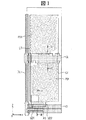
図1は上述した液晶表示装置の画素の一実施例を示す平面図である。また、同図のIII−III線における断面図を図3に、IV−IV線における断面図を図4に示している。
【0031】
まず、透明基板SUB1の表面であって画素領域の下側には図中x方向に延在するゲート信号線GLが形成されている。このゲート信号線GLはたとえばAlあるいはその合金からなっている。
【0032】
このゲート信号線GLは、該画素領域の上側に位置づけられる画素領域の対応するゲート信号線(図示せず)、後述するドレイン信号線DL、該画素領域の右側に位置づけられる画素領域の対応するドレイン信号線(図示せず)とともに、該画素領域を囲むようにして形成されている。
【0033】
また、隣接する各ゲート信号線GLの間に該各ゲート信号線GLと平行に走行する対向電圧信号線CLが形成されている。この対向電圧信号線CLはたとえばゲート信号線GLの形成の際に同時に形成され、たとえばAlあるいはその合金からなっている。
【0034】
また、透明基板SUB1の上面には、前記ゲート信号線GLの形成領域を回避しかつ前記対向電圧信号線CLと電気的に接続するようにして、画素領域の大部分を覆うようにして対向電極CTが形成されている。
【0035】
この対向電極CTは後述する画素電極PIXとの間に電界を発生せしめるもので、反射膜をも兼ねるようにしている。
【0036】
このため、この対向電極CTは光の反射効率の良好な材料が選定され、たとえばAl等で形成される。
【0037】
このようにゲート信号線GL、対向電圧信号線CL、対向電極CTが形成された透明基板SUB1の表面にはこれらゲート信号線GL等をも被ってたとえばSiN等からなる絶縁膜GIが形成されている(図3、図4参照)。
【0038】
この絶縁膜GIは、前記ゲート信号線GL、対向電圧信号線CLに対しては後述のドレイン信号線DLとの層間絶縁膜としての機能を、後述の薄膜トランジスタTFTに対してはそのゲート絶縁膜としての機能を、後述の容量素子Cstgに対してはその誘電体膜としての機能を有するようになっている。
【0039】
そして、前記絶縁膜GIの上面であってゲート信号線GLと重畳する部分にたとえばアモルファスSi(a−Si)からなる半導体層ASが形成されている。
【0040】
この半導体層ASは薄膜トランジスタTFTの半導体層となり、この上面にドレイン電極SD1およびソース電極SD2を形成することによって、ゲート信号線GLの一部をゲート電極とする逆スタガ構造のMIS型トランジスタが形成されるようになっている。
【0041】
なお、この半導体層ASは薄膜トランジスタTFTの形成領域ばかりでなく、後述のドレイン信号線DLの形成領域にも形成されている。該ドレイン信号線DLのゲート信号線GLおよび対向電圧信号線CLに対する層間絶縁膜としての機能を前記絶縁膜GIとともにもたせるためである。
【0042】
薄膜トランジスタTFTのドレイン電極SD1はドレイン信号線DLと同時に形成されるようになっており、この際に、該ドレイン電極SD1と薄膜トランジスタTFTのチャネル長に相当する分だけの間隔を有してソース電極SD2が形成されるようになっている。
【0043】
すなわち、前記絶縁膜GI上にて図中y方向に延在するドレイン信号線DLが形成され、この際に、その一部が前記半導体層ASの上面まで延在させることによってドレイン電極SD1が形成されている。これらドレイン信号線DLおよびドレイン電極SD1はたとえばCrあるいはその合金によって形成されている。
【0044】
また、この際に形成されるソース電極SD2は半導体層ASの形成領域をはみ出して延在され、この延在部は後述する画素電極PIXとの接続を図るコンタクト部となっている。
【0045】
そして、画素領域内における前記絶縁膜GIの表面には図中x方向に延在する帯状パターンからなる複数の画素電極PIXが図中y方向に並設されて形成されている。
【0046】
これら各画素電極PIXは、たとえば対向電圧信号線CLの上方の領域において図中右端で、下方の領域において図中左端で互いに電気的接続がなされ、その一部が前記ソース電極SD2の延在部に重畳されて、該ソース電極SD2と電気的に接続されている。
【0047】
なお、この画素電極PIXは前記対向電圧信号線CLおよび前記対向電極CTと重畳する部分に前記絶縁膜GIを誘電体膜とする容量素子Cstgが形成されている。
【0048】
また、図中x方向へ延在する各画素電極PIXは、そのほぼ中央部にてたとえば一つの屈曲部を有し、いわゆる逆’へ’の字状のパターンとなっている。
【0049】
これは画素領域の図中右半分と左半分の各領域において、画素電極をたとえばゲート信号線GLの走行方向に対し、それぞれθ、(180°−θ)の角度を持たせることにより、各領域に発生する電界の方向を異ならしめている。
【0050】
このような構成はいわゆるマルチドメイン方式と称され、観察者の液晶表示部を観察する際の角度によって色調の変化が生じるのを回避した構成となっている。
【0051】
この趣旨から、この画素電極PIXは、図1に示すような構成とせず、たとえば図中y方向に画素電極PIXを延在させ、その延在方向に幾つかの屈曲部を形成するようにして形成してもよいことはいうまでもない。
【0052】
薄膜トランジスタTFTを介してドレイン信号線DLからの映像信号が供給された画素電極PIXは、前記対向電極CT(映像信号に対して基準となる電圧が印加される)との間において電界を発生せしめ、この電界のうち透明基板SUB1とほぼ平行な成分を有する電界によって液晶LCの光の透過率を制御するようになっている。
【0053】
なお、この画素電極PIXは金属等の不透明な材料で形成してもよいが、たとえばITO(Indium-Tin-Oxide)膜のように光透過性の材料で形成することによって、画素の開口率を向上させる効果を奏する。
【0054】
このように薄膜トランジスタTFT、ドレイン信号線DL、画素電極PIXが形成された透明基板SUB1の表面には該薄膜トランジスタTFT等をも被ってたとえばSiN等からなる保護膜PSVが形成されている(図3、図4、参照)。この保護膜PSVは主として薄膜トランジスタTFTの液晶LCとの直接の接触を回避させ、該薄膜トランジスタTFTの特性劣化を防止させるために形成されている。
【0055】
そして、この保護膜PSVの表面には配向膜ORI2が形成され、その表面に形成されたラビング方向に液晶LCの分子の初期配向方向が規制されるようになっている。
【0056】
また、このように構成された透明基板SUB1と液晶LCを介して対向配置される透明基板SUB2の液晶側の面には、各画素領域を画するようにしてブラックマトリクスBMが形成されている。
【0057】
このブラックマトリクスBMは表示のコントラストを向上させるため、そして、薄膜トランジスタTFTへの外来光の照射を回避するために形成されている。
【0058】
このようにブラックマトリクスBMが形成された透明基板SUB2の表面には、y方向に並設される各画素領域に共通な色のカラーフィルタFILが形成され、x方向にたとえば赤(R)、緑(G)、青(B)の順に配置されている。
【0059】
そして、これらブラックマトリクスBMおよびカラーフィルタFILをも被ってたとえば樹脂膜からなる平坦化膜OCが形成され、この平坦化膜OCの表面には配向膜ORI2が形成されている。この配向膜ORI2のラビング方向は透明基板SUB1側の配向膜のそれと同じになっている。
【0060】
このように構成した液晶表示装置は、その画素領域において多数の画素電極PIXが並設されて形成されている。このため、絶縁膜GIの上面は該画素電極PIXによる凹凸が形成されるとともに、これら画素電極PIXを被う保護膜PSVの表面にも該凹凸が顕在化するようになる。
【0061】
このことは、外来光の照射によって反射される光が前記凹凸によって充分に散乱されるようになる。
【0062】
この場合、画素電極PIXをたとえばITO膜のような透光性の材料で形成した場合、画素の開口率の低下を憂えることなくそれらの間隔を狭くでき、前記凹凸を多くできることから、反射光の散乱の効果を大きくすることができる。
【0063】
そして、前記画素電極PIXは、それが透光性あるいは非透光性の材料で構成されようとも、その電極幅と隣接する他の画素電極PIXとの離間距離(電極間間隔)との関係において、該電極幅に対して電極間間隔が1/2〜2倍であることによって、画素の開口率を低減させることなく反射光の散乱を充分なものとできることが確かめられた。
【0064】
実施例2.
図5は、本発明による液晶表示装置の他の実施例を示す平面図で、図1と対応した図となっている。また、図6は図5のVI−VI線における断面図である。
【0065】
図1の場合と異なる構成は、絶縁膜GIの上面に保護膜PSVが形成され、画素電極PIXは該保護膜PSVの上面に形成されていることにある。
【0066】
このため、該画素電極PIXは、前記絶縁膜GI上に形成される薄膜トランジスタTFTのソース電極SD2と該保護膜PSVに形成されたコンタクト孔CH2を通して電気的に接続されている。
【0067】
このように構成された液晶表示装置は、図1の場合と同様、その画素領域において保護膜PSVの表面に画素電極PIXによる凹凸が形成されるようになり、この凹凸によって反射膜である対向電極からの反射光を錯乱させることができる。
【0068】
実施例3.
図7は、本発明による液晶表示装置の他の実施例を示す平面図で、図5と対応した図となっている。また、図8は図7のVIII−VIII線における断面図(透明基板SUB2側の構成は図示していない)である。
【0069】
図5の場合と異なる構成は、絶縁膜GIの上面に反射膜である対向電極CTが形成され、対向電極CTの上面に保護膜PSVが形成されていることにある。
【0070】
このため、該対向電極CTは、前記絶縁膜GI下に形成される対向電圧信号線CLと該保護膜PSVおよび絶縁膜GIを貫通して形成されたコンタクト孔CH3、該保護膜PSVに形成されたコンタクト孔CH3’を通して電気的に接続されている。
【0071】
このように構成された液晶表示装置も、その画素領域において保護膜PSVの表面に画素電極PIXによる凹凸が形成されるようになり、この凹凸によって反射膜である対向電極からの反射光を錯乱させることができる。
【0072】
実施例4.
図9は、本発明による液晶表示装置の他の実施例を示す平面図で、図1と対応した図となっている。また、図10は図9のX−X線における断面図(透明基板SUB2側の構成は図示していない)である。
【0073】
図1の場合と異なる構成は、まず、保護膜PSVがたとえばSiN等の無機材からなる保護膜PSV1と樹脂等の有機材からなる保護膜PSV2との順次積層体で構成されていることにある。このような保護膜PSVはそれ自体の誘電率を小さくでき、たとえば画素電極PIXと対向電極CTとの間に生じる電界による残像の発生を抑制することができる。
【0074】
また、対向電極CTの一部は、ドレイン信号線に重畳させることで開口率の向上を図ることができる。
【0075】
そして、保護膜PSV(正確には保護膜PSV2)の上面に形成された電極はたとえばITO膜等からなる対向電極CTとなっており、保護膜PSV2およびPSV1、絶縁膜GIを貫通して形成したコンタクト孔CH4を通して対向電圧信号線CLと電気的に接続されている。
【0076】
なお、この実施例では、対向電極CTをたとえば図中y方向へ直線的に延在する帯状の電極を図中x方向に並設させ、その下側の一端を共通接続させたパターンとして構成し、該共通接続された部分で前記コンタクト孔CH4を通して対向電圧信号線CLと電気的に接続させている。
【0077】
このため、該対向電圧信号線CLはゲート信号線GLに近接して隣接するように形成している。
【0078】
画素電極PIXは、前記対向電圧信号線CLの形成領域を回避して該対向電圧信号線CLと同層に形成され、保護膜PSV2およびPSV1、絶縁膜GIを貫通して形成されたコンタクト孔CH5、保護膜PSV2およびPSV1を貫通して形成されたコンタクト孔CH5’を通して該絶縁膜GI上に形成された薄膜トランジスタTFTのソース電極SD2と電気的な接続が図れている。
【0079】
このようにした場合にも、その画素領域において保護膜PSVの表面に対向電極CTによる凹凸が形成されるようになり、この凹凸によって反射膜である画素電極PIXからの反射光を錯乱させることができる。
【0080】
実施例5.
図11は、本発明による液晶表示装置の他の実施例を示す平面図で、図9と対応した図となっている。また、図12は図11のXII−XII線における断面図である。
【0081】
図9の場合と異なる構成は、反射膜である画素電極PIXは絶縁膜GI上に形成されていることにある。
【0082】
この場合、絶縁膜GIの上面には薄膜トランジスタTFTのソース電極SD2が形成されていることから、それらを重畳させて形成されることによって電気的接続が図れ、コンタクト孔を通すことなく行うことができる。
【0083】
実施例6.
図13は、本発明による液晶表示装置の他の実施例を示す平面図で、図11と対応した図となっている。また、図14は図13のXIV−XIV線における断面図である。
【0084】
図13の場合と異なる構成は、反射膜である画素電極PIXは無機材からなる保護膜PSV1上に形成されていることにある。
【0085】
この場合、該画素電極PIXは前記保護膜PSV1に形成したコンタクト孔CH6を通して絶縁膜GIの上面の薄膜トランジスタTFTのソース電極SD2に電気的接続がなされるようになっている。
【0086】
実施例7.
上述した各実施例は、そのいずれにおいても、画素領域の全域にわたって外来光を反射させる反射膜が形成されたものである。
【0087】
しかし、たとえば画素領域の約半分の領域において反射膜を形成し、他の残りの約半分の領域において該反射膜と電気的に接続された透光性の材料膜(たとえばITO膜)を形成し、これらを画素電極あるいは対向電極として形成するようにしてもよい。必要な際には透過型あるいは反射型として用いられるいわゆる一部反射型の液晶表示装置を得ることができる。
【0088】
この場合、他方の電極(対向電極あるいは画素電極)は上述した各実施例のようなパターンとし、これにより前記反射膜からの反射光を充分に散乱させることができる。
【0089】
【発明の効果】
以上説明したことから明らかなように、本発明による液晶表示装置によれば、特別な構成を施すことなく反射型として信頼性の優れたものを得ることができる。
【図面の簡単な説明】
【図1】本発明による液晶表示装置の画素の一実施例を示す平面図である。
【図2】本発明による液晶表示装置の一実施例を示す全体等価回路図である。
【図3】図1のIII−III線における断面図である。
【図4】図1のIV−IV線における断面図である。
【図5】本発明による液晶表示装置の画素の他の実施例を示す平面図である。
【図6】図5のVI−VI線における断面図である。
【図7】本発明による液晶表示装置の画素の他の実施例を示す平面図である。
【図8】図7のVIII−VIII線における断面図である。
【図9】本発明による液晶表示装置の画素の他の実施例を示す平面図である。
【図10】図9のX−X線における断面図である。
【図11】本発明による液晶表示装置の画素の他の実施例を示す平面図である。
【図12】図11のXII−XII線における断面図である。
【図13】本発明による液晶表示装置の画素の他の実施例を示す平面図である。
【図14】図13のXIV−XIV線における断面図である。
【符号の説明】
SUB1,SUB2…透明基板、GL…ゲート信号線、DL…ドレイン信号線、CL…対向電圧信号線、GI…絶縁膜、AS…半導体層、TFT…薄膜トランジスタ、SD1…ドレイン電極、SD2…ソース電極、PSV…保護膜、PSV1…無機材からなる保護膜、PSV2…有機材からなる保護膜、PIX…画素電極、CT…対向電極。[0001]
BACKGROUND OF THE INVENTION
The present invention relates to a liquid crystal display device, and more particularly to a liquid crystal display device called a reflection type.
[0002]
[Prior art]
The liquid crystal display device includes a pair of substrates opposed to each other with liquid crystal as an envelope, and includes a liquid crystal display unit including a large number of pixels in the liquid crystal spreading direction.
[0003]
The light transmittance of the liquid crystal of each pixel is controlled by the strength of the electric field applied thereto.
[0004]
In addition, a liquid crystal display device called a reflection type is a surface on the liquid crystal side of one of the substrates, and at least the entire pixel region (or part: in this case, the partial reflection type). A reflective film having a good light reflection efficiency. In this case, this reflective film usually constitutes one electrode when an electric field is applied to the liquid crystal.
[0005]
An external light is incident on the liquid crystal display unit of the liquid crystal display device, and an image on the liquid crystal display unit can be recognized by observing the light reflected by the reflective film through the liquid crystal of each pixel.
[0006]
[Problems to be solved by the invention]
However, in the reflection type liquid crystal display device configured as described above, the reflection film may be configured such that irregularities are formed on the surface thereof, thereby scattering the irradiation direction of the reflected light to some extent. desirable.
[0007]
This is because in the case of a reflective film having a flat surface, the observer's face or its background may be clearly reflected when the observer observes the liquid crystal display unit.
[0008]
However, processing the reflective film as described above leads to an increase in the manufacturing process and other contrivances have been made.
[0009]
The present invention has been made based on such circumstances, and an object of the present invention is to provide a liquid crystal display device having excellent reliability as a reflection type without applying a special configuration.
[0010]
[Means for Solving the Problems]
Of the inventions disclosed in the present invention, the outline of typical ones will be briefly described as follows.
[0011]
The liquid crystal display device according to the present invention includes, for example, one electrode, an insulating layer, and the other on each pixel region on the liquid crystal side of one of the substrates that are opposed to each other through the liquid crystal. The one electrode is formed as a reflection film, and the other electrode extends in one direction within the region where the one electrode is formed and is aligned in a direction crossing the one direction. It is formed from a plurality of provided electrodes.
[0012]
In the liquid crystal display device configured as described above, the upper layer through the insulating film of one electrode that also serves as a reflective film is formed as a surface on which irregularities are formed by the other electrode.
[0013]
For this reason, extraneous light enters the reflective film via the liquid crystal, and the light reflected by the reflective film is scattered by the irregularities.
[0014]
Therefore, a liquid crystal display device having excellent reliability as a reflective type can be obtained without applying a special configuration.
[0015]
DETAILED DESCRIPTION OF THE INVENTION
Hereinafter, embodiments of a liquid crystal display device according to the present invention will be described with reference to the drawings.
[0016]
Example 1.
<< Equivalent circuit >>
FIG. 2 is a diagram showing an equivalent circuit of the liquid crystal display device according to the present invention. This figure is an equivalent circuit, but corresponds to the actual geometric arrangement.
[0017]
In the figure, there is a transparent substrate SUB1, and this transparent substrate SUB1 is arranged to face another transparent substrate SUB2 via a liquid crystal.
[0018]
On the surface of the transparent substrate SUB1 on the liquid crystal side, a gate signal line GL extending in the x direction and arranged in parallel in the y direction in the figure, and insulated from the gate signal line GL and extending in the y direction, extending in the x direction. The drain signal lines DL arranged in parallel to each other are formed, and a rectangular region surrounded by these signal lines becomes a pixel region, and the display portion AR is configured by a set of these pixel regions.
[0019]
Further, a counter voltage signal line CL disposed in parallel with the gate signal line GL is formed between the gate signal lines GL. Each of these counter voltage signal lines CL is supplied with a reference signal (voltage) for a video signal to be described later, and is connected to a counter electrode CT to be described later in each pixel region. .
[0020]
Each pixel region is supplied with a thin film transistor TFT driven by supply of a scanning signal (voltage) from one gate signal line GL, and a video signal (voltage) from one drain signal line DL via the thin film transistor TFT. A pixel electrode PIX is formed.
[0021]
In addition, a capacitive element Cstg is formed between the pixel electrode PIX and the counter voltage signal line CL, and when the thin film transistor TFT is turned off, the capacitive element Cstg accumulates a video signal supplied to the pixel electrode PIX for a long time. It is supposed to let you.
[0022]
The pixel electrode PIX in each pixel region generates an electric field having a component substantially parallel to the transparent substrate SUB1 between the pixel electrode PX and the adjacent counter electrode CT. The light transmittance of the liquid crystal in the region is controlled.
[0023]
One end of each gate signal line GL extends to one side (left side in the figure) of the transparent substrate, and the extending portion is connected to a bump of the semiconductor integrated circuit GDRC including a vertical scanning circuit mounted on the transparent substrate SUB1. A terminal portion GTM is formed, and one end of each drain signal line DL is also extended to one side (upper side in the drawing) of the transparent substrate SUB1, and the extending portion is a video signal drive mounted on the transparent substrate SUB1. Terminal portions DTM connected to the bumps of the semiconductor integrated circuit DDRC composed of circuits are formed.
[0024]
Each of the semiconductor integrated circuits GDRC and DDRC is completely mounted on the transparent substrate SUB1 and is called a so-called COG (chip on glass) system.
[0025]
The bumps on the input side of the semiconductor integrated circuits GDRC and DDRC are also connected to the terminal portions GTM2 and DTM2 formed on the transparent substrate SUB1, respectively. These terminal portions GTM2 and DTM2 are connected via the wiring layers. Of the periphery of the transparent substrate SUB1, it is connected to the terminal portions GTM3 and DTM3 respectively arranged in the portion closest to the end face.
[0026]
One end (right end) of each counter voltage signal line CL is connected in common and extends to the end side of the transparent substrate SUB1 and is connected to the terminal portion CTM.
[0027]
The transparent substrate SUB2 is disposed to face the transparent substrate SUB1 so as to avoid a region where the semiconductor integrated circuit is mounted, and has a smaller area than the transparent substrate SUB1.
[0028]
The transparent substrate SUB2 is fixed to the transparent substrate SUB1 by a sealing material SL formed around the transparent substrate SUB2. The sealing material SL also functions to seal the liquid crystal between the transparent substrates SUB1 and SUB2. ing.
[0029]
In the above description, the liquid crystal display device using the COG method has been described. However, the present invention can also be applied to a TCP method. Here, the TCP method is a semiconductor integrated circuit formed by a tape carrier method, and its output terminal is connected to a terminal portion formed on the transparent substrate SUB1, and the input terminal is close to the transparent substrate SUB1. It is connected to the terminal part on the printed circuit board to be arranged.
[0030]
Further, the liquid crystal display device having the above configuration is used as a so-called desktop type or laptop type, but the present invention can also be applied to a liquid crystal display device of a cellular phone.
<Pixel configuration>
FIG. 1 is a plan view showing one embodiment of a pixel of the liquid crystal display device described above. 3 is a cross-sectional view taken along line III-III in FIG. 3, and FIG. 4 is a cross-sectional view taken along line IV-IV.
[0031]
First, a gate signal line GL extending in the x direction in the drawing is formed on the surface of the transparent substrate SUB1 and below the pixel region. The gate signal line GL is made of, for example, Al or an alloy thereof.
[0032]
The gate signal line GL includes a gate signal line (not shown) corresponding to the pixel region positioned above the pixel region, a drain signal line DL described later, and a drain corresponding to the pixel region positioned on the right side of the pixel region. A signal line (not shown) is formed so as to surround the pixel region.
[0033]
Further, a counter voltage signal line CL that runs parallel to each gate signal line GL is formed between each adjacent gate signal line GL. The counter voltage signal line CL is formed simultaneously with the formation of the gate signal line GL, for example, and is made of, for example, Al or an alloy thereof.
[0034]
Further, on the upper surface of the transparent substrate SUB1, a counter electrode is formed so as to cover a large part of the pixel region so as to avoid the formation region of the gate signal line GL and to be electrically connected to the counter voltage signal line CL. CT is formed.
[0035]
The counter electrode CT generates an electric field with a pixel electrode PIX, which will be described later, and also serves as a reflection film.
[0036]
For this reason, the counter electrode CT is made of a material having a good light reflection efficiency, and is made of, for example, Al.
[0037]
Thus, an insulating film GI made of, for example, SiN is formed on the surface of the transparent substrate SUB1 on which the gate signal line GL, the counter voltage signal line CL, and the counter electrode CT are formed so as to cover the gate signal line GL. (See FIGS. 3 and 4).
[0038]
This insulating film GI functions as an interlayer insulating film with the drain signal line DL described later for the gate signal line GL and the counter voltage signal line CL, and as a gate insulating film for the thin film transistor TFT described later. This function has a function as a dielectric film for a capacitive element Cstg described later.
[0039]
A semiconductor layer AS made of, for example, amorphous Si (a-Si) is formed on the upper surface of the insulating film GI and in a portion overlapping with the gate signal line GL.
[0040]
This semiconductor layer AS becomes a semiconductor layer of the thin film transistor TFT, and by forming the drain electrode SD1 and the source electrode SD2 on the upper surface, an inverted staggered MIS transistor having a part of the gate signal line GL as a gate electrode is formed. It has become so.
[0041]
The semiconductor layer AS is formed not only in the formation region of the thin film transistor TFT but also in the formation region of the drain signal line DL described later. This is because the drain signal line DL has a function as an interlayer insulating film with respect to the gate signal line GL and the counter voltage signal line CL together with the insulating film GI.
[0042]
The drain electrode SD1 of the thin film transistor TFT is formed simultaneously with the drain signal line DL. At this time, the source electrode SD2 is spaced from the drain electrode SD1 by an amount corresponding to the channel length of the thin film transistor TFT. Is to be formed.
[0043]
That is, a drain signal line DL extending in the y direction in the drawing is formed on the insulating film GI, and at this time, a part of the drain signal line DL extends to the upper surface of the semiconductor layer AS, thereby forming the drain electrode SD1. Has been. The drain signal line DL and the drain electrode SD1 are made of, for example, Cr or an alloy thereof.
[0044]
Further, the source electrode SD2 formed at this time extends beyond the formation region of the semiconductor layer AS, and this extended portion serves as a contact portion for connection to a pixel electrode PIX described later.
[0045]
A plurality of pixel electrodes PIX each having a strip-like pattern extending in the x direction in the drawing are arranged in parallel in the y direction in the drawing on the surface of the insulating film GI in the pixel region.
[0046]
These pixel electrodes PIX are electrically connected to each other at the right end in the drawing in the region above the counter voltage signal line CL and at the left end in the drawing in the lower region, for example, and a part of the pixel electrode PIX extends from the source electrode SD2. Is electrically connected to the source electrode SD2.
[0047]
In the pixel electrode PIX, a capacitive element Cstg having the insulating film GI as a dielectric film is formed in a portion overlapping the counter voltage signal line CL and the counter electrode CT.
[0048]
Further, each pixel electrode PIX extending in the x direction in the drawing has, for example, one bent portion at a substantially central portion thereof, and has a so-called reverse “height” pattern.
[0049]
This is because each pixel region has an angle of θ and (180 ° −θ) with respect to the traveling direction of the gate signal line GL, for example, in each of the right half and the left half of the pixel region. The direction of the electric field generated in is different.
[0050]
Such a configuration is referred to as a so-called multi-domain system, and is a configuration that avoids a change in color tone depending on an angle at which the observer observes the liquid crystal display unit.
[0051]
For this purpose, the pixel electrode PIX is not configured as shown in FIG. 1. For example, the pixel electrode PIX extends in the y direction in the drawing and several bent portions are formed in the extending direction. Needless to say, it may be formed.
[0052]
The pixel electrode PIX to which the video signal from the drain signal line DL is supplied via the thin film transistor TFT generates an electric field between the counter electrode CT (a reference voltage is applied to the video signal), Of this electric field, the light transmittance of the liquid crystal LC is controlled by an electric field having a component substantially parallel to the transparent substrate SUB1.
[0053]
The pixel electrode PIX may be formed of an opaque material such as a metal. For example, the pixel electrode PIX may be formed of a light transmissive material such as an ITO (Indium-Tin-Oxide) film, thereby reducing the aperture ratio of the pixel. There is an effect to improve.
[0054]
Thus, a protective film PSV made of, for example, SiN is formed on the surface of the transparent substrate SUB1 on which the thin film transistor TFT, the drain signal line DL, and the pixel electrode PIX are formed (FIG. 3, FIG. 3). FIG. 4). The protective film PSV is formed mainly to avoid direct contact of the thin film transistor TFT with the liquid crystal LC and to prevent deterioration of the characteristics of the thin film transistor TFT.
[0055]
An alignment film ORI2 is formed on the surface of the protective film PSV, and the initial alignment direction of the molecules of the liquid crystal LC is regulated in the rubbing direction formed on the surface.
[0056]
Further, a black matrix BM is formed on the liquid crystal side surface of the transparent substrate SUB2 that is arranged so as to face the transparent substrate SUB1 thus configured through the liquid crystal LC so as to define each pixel region.
[0057]
The black matrix BM is formed in order to improve display contrast and to avoid irradiation of extraneous light to the thin film transistor TFT.
[0058]
Thus, on the surface of the transparent substrate SUB2 on which the black matrix BM is formed, a color filter FIL having a color common to the pixel regions arranged in parallel in the y direction is formed. For example, red (R), green They are arranged in the order of (G) and blue (B).
[0059]
A flattening film OC made of, for example, a resin film is formed covering the black matrix BM and the color filter FIL, and an alignment film ORI2 is formed on the surface of the flattening film OC. The rubbing direction of the alignment film ORI2 is the same as that of the alignment film on the transparent substrate SUB1 side.
[0060]
The liquid crystal display device configured as described above is formed by arranging a large number of pixel electrodes PIX in parallel in the pixel region. For this reason, the upper surface of the insulating film GI has irregularities formed by the pixel electrodes PIX, and the irregularities also appear on the surface of the protective film PSV covering the pixel electrodes PIX.
[0061]
This means that the light reflected by the external light irradiation is sufficiently scattered by the unevenness.
[0062]
In this case, when the pixel electrode PIX is formed of a light-transmitting material such as an ITO film, the interval between them can be narrowed without worrying about a decrease in the aperture ratio of the pixel, and the unevenness can be increased. The effect of scattering can be increased.
[0063]
Even if the pixel electrode PIX is made of a translucent or non-translucent material, the relationship between the electrode width and the distance between the adjacent pixel electrodes PIX (interelectrode spacing) It has been confirmed that when the inter-electrode spacing is 1/2 to 2 times the electrode width, the reflected light can be sufficiently scattered without reducing the aperture ratio of the pixel.
[0064]
Example 2
FIG. 5 is a plan view showing another embodiment of the liquid crystal display device according to the present invention and corresponds to FIG. 6 is a cross-sectional view taken along line VI-VI in FIG.
[0065]
A configuration different from the case of FIG. 1 is that a protective film PSV is formed on the upper surface of the insulating film GI, and the pixel electrode PIX is formed on the upper surface of the protective film PSV.
[0066]
Therefore, the pixel electrode PIX is electrically connected to the source electrode SD2 of the thin film transistor TFT formed on the insulating film GI through the contact hole CH2 formed in the protective film PSV.
[0067]
In the liquid crystal display device configured as described above, as in the case of FIG. 1, unevenness due to the pixel electrode PIX is formed on the surface of the protective film PSV in the pixel region. The reflected light from can be confused.
[0068]
Example 3
FIG. 7 is a plan view showing another embodiment of the liquid crystal display device according to the present invention and corresponds to FIG. 8 is a cross-sectional view taken along line VIII-VIII in FIG. 7 (the configuration on the transparent substrate SUB2 side is not shown).
[0069]
The configuration different from the case of FIG. 5 is that a counter electrode CT, which is a reflective film, is formed on the upper surface of the insulating film GI, and a protective film PSV is formed on the upper surface of the counter electrode CT.
[0070]
Therefore, the counter electrode CT is formed in the counter voltage signal line CL formed under the insulating film GI, the contact hole CH3 formed through the protective film PSV and the insulating film GI, and the protective film PSV. The contact holes CH3 ′ are electrically connected.
[0071]
In the liquid crystal display device configured as described above, unevenness due to the pixel electrode PIX is formed on the surface of the protective film PSV in the pixel region, and the unevenness causes the reflected light from the counter electrode as a reflective film to be confused. be able to.
[0072]
Example 4
FIG. 9 is a plan view showing another embodiment of the liquid crystal display device according to the present invention and corresponds to FIG. FIG. 10 is a cross-sectional view taken along line XX in FIG. 9 (the configuration on the transparent substrate SUB2 side is not shown).
[0073]
The configuration different from the case of FIG. 1 is that the protective film PSV is first composed of a laminated body of a protective film PSV1 made of an inorganic material such as SiN and a protective film PSV2 made of an organic material such as resin. . Such a protective film PSV can reduce the dielectric constant of the protective film PSV, for example, and can suppress generation of an afterimage due to an electric field generated between the pixel electrode PIX and the counter electrode CT.
[0074]
In addition, the aperture ratio can be improved by overlapping a part of the counter electrode CT with the drain signal line.
[0075]
The electrode formed on the upper surface of the protective film PSV (more precisely, the protective film PSV2) is a counter electrode CT made of, for example, an ITO film, and is formed through the protective films PSV2, PSV1, and the insulating film GI. The counter voltage signal line CL is electrically connected through the contact hole CH4.
[0076]
In this embodiment, the counter electrode CT is configured as a pattern in which, for example, strip-like electrodes extending linearly in the y direction in the figure are arranged in parallel in the x direction in the figure and the lower ends thereof are connected in common. The common connection portion is electrically connected to the counter voltage signal line CL through the contact hole CH4.
[0077]
Therefore, the counter voltage signal line CL is formed so as to be adjacent to and adjacent to the gate signal line GL.
[0078]
The pixel electrode PIX is formed in the same layer as the counter voltage signal line CL while avoiding the formation region of the counter voltage signal line CL, and the contact hole CH5 formed through the protective films PSV2 and PSV1 and the insulating film GI. The thin film transistor TFT formed on the insulating film GI is electrically connected to the source electrode SD2 through the contact hole CH5 ′ formed through the protective films PSV2 and PSV1.
[0079]
Even in this case, unevenness due to the counter electrode CT is formed on the surface of the protective film PSV in the pixel region, and this unevenness causes the reflected light from the pixel electrode PIX that is the reflective film to be confused. it can.
[0080]
Example 5 FIG.
FIG. 11 is a plan view showing another embodiment of the liquid crystal display device according to the present invention and corresponds to FIG. 12 is a cross-sectional view taken along line XII-XII in FIG.
[0081]
The configuration different from the case of FIG. 9 is that the pixel electrode PIX which is a reflective film is formed on the insulating film GI.
[0082]
In this case, since the source electrode SD2 of the thin film transistor TFT is formed on the upper surface of the insulating film GI, an electrical connection can be achieved by forming the source electrode SD2 so as not to pass through the contact hole. .
[0083]
Example 6
FIG. 13 is a plan view showing another embodiment of the liquid crystal display device according to the present invention and corresponds to FIG. 14 is a cross-sectional view taken along line XIV-XIV in FIG.
[0084]
The configuration different from the case of FIG. 13 is that the pixel electrode PIX which is a reflective film is formed on the protective film PSV1 made of an inorganic material.
[0085]
In this case, the pixel electrode PIX is electrically connected to the source electrode SD2 of the thin film transistor TFT on the upper surface of the insulating film GI through the contact hole CH6 formed in the protective film PSV1.
[0086]
Example 7
In each of the embodiments described above, a reflective film that reflects extraneous light is formed over the entire pixel region.
[0087]
However, for example, a reflective film is formed in about half of the pixel area, and a light-transmitting material film (for example, ITO film) electrically connected to the reflective film is formed in the other half of the area. These may be formed as pixel electrodes or counter electrodes. When necessary, a so-called partially reflective liquid crystal display device used as a transmission type or a reflection type can be obtained.
[0088]
In this case, the other electrode (counter electrode or pixel electrode) has a pattern as in each of the embodiments described above, so that the reflected light from the reflective film can be sufficiently scattered.
[0089]
【Effect of the invention】
As is apparent from the above description, according to the liquid crystal display device of the present invention, a reflective type having excellent reliability can be obtained without any special configuration.
[Brief description of the drawings]
FIG. 1 is a plan view showing one embodiment of a pixel of a liquid crystal display device according to the present invention.
FIG. 2 is an overall equivalent circuit diagram showing an embodiment of a liquid crystal display device according to the present invention.
3 is a cross-sectional view taken along line III-III in FIG.
4 is a cross-sectional view taken along line IV-IV in FIG.
FIG. 5 is a plan view showing another embodiment of the pixel of the liquid crystal display device according to the present invention.
6 is a cross-sectional view taken along line VI-VI in FIG.
FIG. 7 is a plan view showing another embodiment of the pixel of the liquid crystal display device according to the present invention.
8 is a cross-sectional view taken along line VIII-VIII in FIG.
FIG. 9 is a plan view showing another embodiment of the pixel of the liquid crystal display device according to the present invention.
10 is a cross-sectional view taken along line XX in FIG.
FIG. 11 is a plan view showing another embodiment of the pixel of the liquid crystal display device according to the present invention.
12 is a cross-sectional view taken along line XII-XII in FIG.
FIG. 13 is a plan view showing another embodiment of the pixel of the liquid crystal display device according to the present invention.
14 is a cross-sectional view taken along line XIV-XIV in FIG.
[Explanation of symbols]
SUB1, SUB2 ... transparent substrate, GL ... gate signal line, DL ... drain signal line, CL ... counter voltage signal line, GI ... insulating film, AS ... semiconductor layer, TFT ... thin film transistor, SD1 ... drain electrode, SD2 ... source electrode, PSV ... protective film, PSV1 ... protective film made of inorganic material, PSV2 ... protective film made of organic material, PIX ... pixel electrode, CT ... counter electrode.
Claims (2)
前記画素領域に、前記ゲート信号線からの走査信号によって作動される薄膜トランジスタと、前記薄膜トランジスタを介して前記ドレイン信号線からの映像信号が供給される画素電極と、前記画素電極との間に電界を生じせしめる対向電極とを備え、
前記画素電極は、反射膜であり、
前記対向電極は絶縁層を介して前記画素電極の上層に形成され、
前記対向電極は前記画素電極の形成領域内で一方向に延在し該一方向と交差する方向に並設された複数の電極から形成され、
前記絶縁層は、前記薄膜トランジスタを被う無機材からなる第1の保護膜を構成する層と、前記第1の保護膜の上面に形成される有機材からなる第2の保護膜を構成する層との積層体となっており、
前記対向電極に対向電圧を供給する対向電圧信号線は前記一方の基板の一端にて共通に接続され端子部に接続されていることを特徴とする液晶表示装置。A pixel region surrounded by a gate signal line adjacent to each other and a drain signal line adjacent to each other on a liquid crystal side surface of one of the substrates disposed opposite to each other through the liquid crystal;
An electric field is applied to the pixel region between the pixel electrode, a thin film transistor operated by a scanning signal from the gate signal line, a pixel electrode to which a video signal from the drain signal line is supplied via the thin film transistor, and the pixel electrode. A counter electrode to be generated,
The pixel electrode is a reflective film;
The counter electrode is formed on an upper layer of the pixel electrode through an insulating layer,
The counter electrode is formed of a plurality of electrodes extending in one direction within the pixel electrode formation region and arranged in parallel in a direction crossing the one direction.
The insulating layer includes a layer constituting a first protective film made of an inorganic material covering the thin film transistor and a layer constituting a second protective film made of an organic material formed on the upper surface of the first protective film. It is a laminate with
A counter voltage signal line for supplying a counter voltage to the counter electrode is commonly connected at one end of the one substrate and connected to a terminal portion.
Priority Applications (5)
| Application Number | Priority Date | Filing Date | Title |
|---|---|---|---|
| JP2001063494A JP5165169B2 (en) | 2001-03-07 | 2001-03-07 | Liquid crystal display |
| TW091101824A TWI309734B (en) | 2001-03-07 | 2002-02-01 | |
| US10/087,791 US6611310B2 (en) | 2001-03-07 | 2002-03-05 | Liquid crystal display device |
| KR1020020011895A KR100569052B1 (en) | 2001-03-07 | 2002-03-06 | Liquid crystal display device |
| CNB02106847XA CN1258109C (en) | 2001-03-07 | 2002-03-06 | Liquid crystal display device |
Applications Claiming Priority (1)
| Application Number | Priority Date | Filing Date | Title |
|---|---|---|---|
| JP2001063494A JP5165169B2 (en) | 2001-03-07 | 2001-03-07 | Liquid crystal display |
Publications (3)
| Publication Number | Publication Date |
|---|---|
| JP2002268074A JP2002268074A (en) | 2002-09-18 |
| JP2002268074A5 JP2002268074A5 (en) | 2008-04-03 |
| JP5165169B2 true JP5165169B2 (en) | 2013-03-21 |
Family
ID=18922481
Family Applications (1)
| Application Number | Title | Priority Date | Filing Date |
|---|---|---|---|
| JP2001063494A Expired - Fee Related JP5165169B2 (en) | 2001-03-07 | 2001-03-07 | Liquid crystal display |
Country Status (5)
| Country | Link |
|---|---|
| US (1) | US6611310B2 (en) |
| JP (1) | JP5165169B2 (en) |
| KR (1) | KR100569052B1 (en) |
| CN (1) | CN1258109C (en) |
| TW (1) | TWI309734B (en) |
Families Citing this family (31)
| Publication number | Priority date | Publication date | Assignee | Title |
|---|---|---|---|---|
| WO2001018597A1 (en) * | 1999-09-07 | 2001-03-15 | Hitachi, Ltd | Liquid crystal display device |
| JP5165169B2 (en) * | 2001-03-07 | 2013-03-21 | 株式会社ジャパンディスプレイイースト | Liquid crystal display |
| JP4647843B2 (en) * | 2001-06-28 | 2011-03-09 | 株式会社日立製作所 | Liquid crystal display device |
| JP4305811B2 (en) | 2001-10-15 | 2009-07-29 | 株式会社日立製作所 | Liquid crystal display device, image display device and manufacturing method thereof |
| JP4162890B2 (en) * | 2001-12-27 | 2008-10-08 | 株式会社日立製作所 | Liquid crystal display |
| JP4117148B2 (en) * | 2002-05-24 | 2008-07-16 | 日本電気株式会社 | Transflective liquid crystal display device |
| KR100892087B1 (en) * | 2002-10-28 | 2009-04-06 | 엘지디스플레이 주식회사 | Array substrate for In-Plane switching mode LCD and the method for fabricating the same |
| US7433005B2 (en) * | 2003-03-31 | 2008-10-07 | Sharp Kabushiki Kaisha | Liquid crystal display device having electrode units each provided with a solid part and an extending part and method of manufacturing the same |
| JP3971778B2 (en) * | 2003-07-14 | 2007-09-05 | 株式会社 日立ディスプレイズ | Display device |
| TWI243936B (en) * | 2003-12-11 | 2005-11-21 | Hannstar Display Corp | Structure of a display panel with compensating electrode |
| CN1627146A (en) * | 2003-12-13 | 2005-06-15 | 鸿富锦精密工业(深圳)有限公司 | Edge electric field switch type liquid crystal display unit |
| JP4223992B2 (en) * | 2004-05-25 | 2009-02-12 | 株式会社 日立ディスプレイズ | Liquid crystal display |
| KR100652218B1 (en) * | 2004-06-29 | 2006-12-01 | 엘지.필립스 엘시디 주식회사 | In plane switching mode liquid crystal display device and method for fabricating thereof |
| JP4623464B2 (en) * | 2005-09-26 | 2011-02-02 | 株式会社 日立ディスプレイズ | Liquid crystal display device |
| CN102331639A (en) | 2005-12-05 | 2012-01-25 | 株式会社半导体能源研究所 | Liquid crystal display device |
| EP2924498A1 (en) * | 2006-04-06 | 2015-09-30 | Semiconductor Energy Laboratory Co, Ltd. | Liquid crystal desplay device, semiconductor device, and electronic appliance |
| JP4884820B2 (en) * | 2006-04-12 | 2012-02-29 | 株式会社 日立ディスプレイズ | Liquid crystal display |
| TWI752316B (en) * | 2006-05-16 | 2022-01-11 | 日商半導體能源研究所股份有限公司 | Liquid crystal display device |
| US7847904B2 (en) | 2006-06-02 | 2010-12-07 | Semiconductor Energy Laboratory Co., Ltd. | Liquid crystal display device and electronic appliance |
| JP2008009425A (en) * | 2006-06-02 | 2008-01-17 | Semiconductor Energy Lab Co Ltd | Liquid crystal display device and electronic appliance |
| JP4201051B2 (en) * | 2006-09-15 | 2008-12-24 | エプソンイメージングデバイス株式会社 | LCD panel |
| CN100590504C (en) * | 2007-11-12 | 2010-02-17 | 昆山龙腾光电有限公司 | LCD device array substrates |
| JP5090133B2 (en) * | 2007-11-14 | 2012-12-05 | パナソニック液晶ディスプレイ株式会社 | Liquid crystal display |
| KR101882827B1 (en) * | 2012-11-02 | 2018-07-30 | 삼성디스플레이 주식회사 | LIQUID CRYSTAL display |
| CN103488002B (en) * | 2013-09-18 | 2015-03-11 | 京东方科技集团股份有限公司 | Pixel electrode, array substrate and display device |
| CN105826328B (en) * | 2016-05-03 | 2019-03-05 | 京东方科技集团股份有限公司 | Array substrate and its manufacturing method, display device |
| CN111505870B (en) * | 2020-05-19 | 2022-08-05 | 武汉京东方光电科技有限公司 | Pixel electrode, pixel structure, display panel and display device |
| CN114063353B (en) * | 2020-07-29 | 2023-11-28 | 京东方科技集团股份有限公司 | Array substrate, liquid crystal display panel and liquid crystal display device |
| CN114981719B (en) * | 2020-10-30 | 2023-09-01 | 京东方科技集团股份有限公司 | Electrode structure, display panel and display device |
| CN114764204A (en) * | 2021-01-13 | 2022-07-19 | 京东方科技集团股份有限公司 | Display panel and electronic device |
| CN115840314A (en) * | 2021-09-18 | 2023-03-24 | 武汉京东方光电科技有限公司 | Display panel, preparation method thereof and display device |
Family Cites Families (16)
| Publication number | Priority date | Publication date | Assignee | Title |
|---|---|---|---|---|
| JPH07159776A (en) * | 1993-12-07 | 1995-06-23 | Casio Comput Co Ltd | Reflection type liquid crystal display device |
| KR100646903B1 (en) * | 1997-04-11 | 2006-11-17 | 가부시키가이샤 히타치세이사쿠쇼 | Liquid crystal display device |
| JP4024901B2 (en) * | 1997-05-22 | 2007-12-19 | エルジー フィリップス エルシーディー カンパニー リミテッド | Active matrix type liquid crystal display device |
| JPH11133399A (en) * | 1997-10-27 | 1999-05-21 | Hitachi Ltd | Reflection type liquid crystal display device and its production |
| US6577368B1 (en) * | 1997-11-03 | 2003-06-10 | Samsung Electronics Co., Ltd. | IPS-LCD having a third electrode having aperture and formed on counter substrate |
| JP3019831B2 (en) * | 1998-03-11 | 2000-03-13 | 日本電気株式会社 | Reflective liquid crystal display device and method of manufacturing the same |
| KR100505179B1 (en) * | 1998-04-20 | 2005-11-01 | 엘지.필립스 엘시디 주식회사 | A liquid crystal display |
| GB9811477D0 (en) * | 1998-05-29 | 1998-07-29 | Sharp Kk | Liquid crystal device |
| KR100299381B1 (en) * | 1998-08-24 | 2002-06-20 | 박종섭 | Liquid crystal display device having high opening ratio and high transmittance and manufacturing method thereof |
| JP4174951B2 (en) * | 1999-04-07 | 2008-11-05 | 株式会社日立製作所 | Liquid crystal display |
| US6075582A (en) * | 1999-04-22 | 2000-06-13 | Chisso Corporation | LCD with zig-zag electrodes on both substrates |
| US6449026B1 (en) * | 1999-06-25 | 2002-09-10 | Hyundai Display Technology Inc. | Fringe field switching liquid crystal display and method for manufacturing the same |
| KR100494682B1 (en) * | 1999-06-30 | 2005-06-13 | 비오이 하이디스 테크놀로지 주식회사 | Liquid crystal display and manufacturing method thereof |
| TW495626B (en) * | 1999-09-13 | 2002-07-21 | Ind Tech Res Inst | Electrode structure for a wide viewing angle liquid crystal display |
| JP3832261B2 (en) * | 2000-03-16 | 2006-10-11 | セイコーエプソン株式会社 | Liquid crystal device, projection display device, and electronic apparatus |
| JP5165169B2 (en) * | 2001-03-07 | 2013-03-21 | 株式会社ジャパンディスプレイイースト | Liquid crystal display |
-
2001
- 2001-03-07 JP JP2001063494A patent/JP5165169B2/en not_active Expired - Fee Related
-
2002
- 2002-02-01 TW TW091101824A patent/TWI309734B/zh not_active IP Right Cessation
- 2002-03-05 US US10/087,791 patent/US6611310B2/en not_active Expired - Lifetime
- 2002-03-06 KR KR1020020011895A patent/KR100569052B1/en not_active IP Right Cessation
- 2002-03-06 CN CNB02106847XA patent/CN1258109C/en not_active Expired - Lifetime
Also Published As
| Publication number | Publication date |
|---|---|
| CN1374546A (en) | 2002-10-16 |
| CN1258109C (en) | 2006-05-31 |
| JP2002268074A (en) | 2002-09-18 |
| KR20020071764A (en) | 2002-09-13 |
| US6611310B2 (en) | 2003-08-26 |
| KR100569052B1 (en) | 2006-04-10 |
| TWI309734B (en) | 2009-05-11 |
| US20020126241A1 (en) | 2002-09-12 |
Similar Documents
| Publication | Publication Date | Title |
|---|---|---|
| JP5165169B2 (en) | Liquid crystal display | |
| JP3949897B2 (en) | Liquid crystal display | |
| US11774809B2 (en) | Liquid crystal display panel | |
| JP3971778B2 (en) | Display device | |
| JP4002105B2 (en) | Liquid crystal display | |
| CN101419368B (en) | Lateral electric field active matrix addressing liquid crystal display device | |
| JP5261237B2 (en) | LCD panel | |
| US8339557B2 (en) | Liquid crystal display panel | |
| EP1087255A2 (en) | Liquid crystal display device | |
| JP4167085B2 (en) | Liquid crystal display | |
| JP2005148534A (en) | Liquid crystal display device | |
| US6762815B2 (en) | In-plane switching LCD with a redundancy structure for an opened common electrode and a high storage capacitance | |
| US20110267571A1 (en) | Array substrate for in-plane switching mode liquid crystal display device | |
| JP4606103B2 (en) | Liquid crystal display device | |
| KR20050115098A (en) | Liquid crystal display having multi domain and panel for the same | |
| US8031313B2 (en) | Lateral electric field type liquid crystal display device | |
| WO2010131552A1 (en) | Liquid crystal display device | |
| KR20090054255A (en) | Liquid crystal display device | |
| KR20060114921A (en) | Liquid crystal display | |
| JP2019128429A (en) | Liquid crystal display unit | |
| JP2020140157A (en) | Liquid crystal display | |
| US10890815B2 (en) | Display apparatus | |
| KR20050078762A (en) | Thin film transistor array panel and liquid crystal display including the panel | |
| JP2002323704A (en) | Liquid crystal display device | |
| JP5258603B2 (en) | Liquid crystal display |
Legal Events
| Date | Code | Title | Description |
|---|---|---|---|
| A521 | Written amendment |
Free format text: JAPANESE INTERMEDIATE CODE: A523 Effective date: 20080214 |
|
| A621 | Written request for application examination |
Free format text: JAPANESE INTERMEDIATE CODE: A621 Effective date: 20080214 |
|
| A977 | Report on retrieval |
Free format text: JAPANESE INTERMEDIATE CODE: A971007 Effective date: 20101220 |
|
| A131 | Notification of reasons for refusal |
Free format text: JAPANESE INTERMEDIATE CODE: A131 Effective date: 20110118 |
|
| A521 | Written amendment |
Free format text: JAPANESE INTERMEDIATE CODE: A523 Effective date: 20110318 |
|
| A711 | Notification of change in applicant |
Free format text: JAPANESE INTERMEDIATE CODE: A712 Effective date: 20110513 |
|
| RD03 | Notification of appointment of power of attorney |
Free format text: JAPANESE INTERMEDIATE CODE: A7423 Effective date: 20110513 |
|
| A131 | Notification of reasons for refusal |
Free format text: JAPANESE INTERMEDIATE CODE: A131 Effective date: 20110809 |
|
| A521 | Written amendment |
Free format text: JAPANESE INTERMEDIATE CODE: A523 Effective date: 20111007 |
|
| A131 | Notification of reasons for refusal |
Free format text: JAPANESE INTERMEDIATE CODE: A131 Effective date: 20120501 |
|
| A521 | Written amendment |
Free format text: JAPANESE INTERMEDIATE CODE: A523 Effective date: 20120625 |
|
| TRDD | Decision of grant or rejection written | ||
| A01 | Written decision to grant a patent or to grant a registration (utility model) |
Free format text: JAPANESE INTERMEDIATE CODE: A01 Effective date: 20121218 |
|
| A61 | First payment of annual fees (during grant procedure) |
Free format text: JAPANESE INTERMEDIATE CODE: A61 Effective date: 20121219 |
|
| FPAY | Renewal fee payment (event date is renewal date of database) |
Free format text: PAYMENT UNTIL: 20151228 Year of fee payment: 3 |
|
| R150 | Certificate of patent or registration of utility model |
Free format text: JAPANESE INTERMEDIATE CODE: R150 Ref document number: 5165169 Country of ref document: JP Free format text: JAPANESE INTERMEDIATE CODE: R150 |
|
| R250 | Receipt of annual fees |
Free format text: JAPANESE INTERMEDIATE CODE: R250 |
|
| R250 | Receipt of annual fees |
Free format text: JAPANESE INTERMEDIATE CODE: R250 |
|
| R250 | Receipt of annual fees |
Free format text: JAPANESE INTERMEDIATE CODE: R250 |
|
| R250 | Receipt of annual fees |
Free format text: JAPANESE INTERMEDIATE CODE: R250 |
|
| LAPS | Cancellation because of no payment of annual fees |