JP5150601B2 - Mobile communication terminal, mobile communication control apparatus, mobile communication system, and mobile communication method - Google Patents
Mobile communication terminal, mobile communication control apparatus, mobile communication system, and mobile communication method Download PDFInfo
- Publication number
- JP5150601B2 JP5150601B2 JP2009241908A JP2009241908A JP5150601B2 JP 5150601 B2 JP5150601 B2 JP 5150601B2 JP 2009241908 A JP2009241908 A JP 2009241908A JP 2009241908 A JP2009241908 A JP 2009241908A JP 5150601 B2 JP5150601 B2 JP 5150601B2
- Authority
- JP
- Japan
- Prior art keywords
- communication system
- communication
- mobile communication
- communication terminal
- transition
- Prior art date
- Legal status (The legal status is an assumption and is not a legal conclusion. Google has not performed a legal analysis and makes no representation as to the accuracy of the status listed.)
- Active
Links
- 238000010295 mobile communication Methods 0.000 title claims abstract description 125
- 238000000034 method Methods 0.000 title claims description 21
- 238000004891 communication Methods 0.000 claims abstract description 424
- 230000007704 transition Effects 0.000 claims description 78
- 230000005540 biological transmission Effects 0.000 claims description 3
- 230000004044 response Effects 0.000 abstract description 8
- 238000010586 diagram Methods 0.000 description 10
- 230000006870 function Effects 0.000 description 4
- 238000011084 recovery Methods 0.000 description 3
- 230000000694 effects Effects 0.000 description 2
- 230000007774 longterm Effects 0.000 description 2
Images


Classifications
-
- H—ELECTRICITY
- H04—ELECTRIC COMMUNICATION TECHNIQUE
- H04W—WIRELESS COMMUNICATION NETWORKS
- H04W88/00—Devices specially adapted for wireless communication networks, e.g. terminals, base stations or access point devices
- H04W88/02—Terminal devices
- H04W88/06—Terminal devices adapted for operation in multiple networks or having at least two operational modes, e.g. multi-mode terminals
-
- H—ELECTRICITY
- H04—ELECTRIC COMMUNICATION TECHNIQUE
- H04W—WIRELESS COMMUNICATION NETWORKS
- H04W36/00—Hand-off or reselection arrangements
- H04W36/0005—Control or signalling for completing the hand-off
- H04W36/0055—Transmission or use of information for re-establishing the radio link
- H04W36/0066—Transmission or use of information for re-establishing the radio link of control information between different types of networks in order to establish a new radio link in the target network
-
- H—ELECTRICITY
- H04—ELECTRIC COMMUNICATION TECHNIQUE
- H04W—WIRELESS COMMUNICATION NETWORKS
- H04W36/00—Hand-off or reselection arrangements
- H04W36/14—Reselecting a network or an air interface
-
- H—ELECTRICITY
- H04—ELECTRIC COMMUNICATION TECHNIQUE
- H04W—WIRELESS COMMUNICATION NETWORKS
- H04W48/00—Access restriction; Network selection; Access point selection
- H04W48/18—Selecting a network or a communication service
-
- H—ELECTRICITY
- H04—ELECTRIC COMMUNICATION TECHNIQUE
- H04W—WIRELESS COMMUNICATION NETWORKS
- H04W48/00—Access restriction; Network selection; Access point selection
- H04W48/20—Selecting an access point
-
- H—ELECTRICITY
- H04—ELECTRIC COMMUNICATION TECHNIQUE
- H04W—WIRELESS COMMUNICATION NETWORKS
- H04W76/00—Connection management
- H04W76/30—Connection release
Abstract
Description
第1通信システムから第2通信システムに遷移するように構成された移動通信端末、移動通信制御装置、移動通信システム及び移動通信方法に関する。 The present invention relates to a mobile communication terminal, a mobile communication control device, a mobile communication system, and a mobile communication method configured to transition from a first communication system to a second communication system.
UMTS(Universal Mobile Telecommunication System)などの第1通信システムにおいて、アイドル状態又はコネクト状態の移動通信端末は、ネットワークから報知される情報に従って、GSM(Global System for Mobile Communication)やLTE(Long Term Evolution)などの第2通信システムに遷移できる(例えば、特許文献1)。 In a first communication system such as UMTS (Universal Mobile Telecommunication System), an idle or connected mobile communication terminal is in accordance with information broadcast from the network, such as GSM (Global System for Mobile Communication) or LTE (Long Term Term). (For example, patent document 1).
ここで、第1通信システムから第2通信システムに移動通信端末が遷移する場合に、第1通信システムにおいて通信リソースの解放を検出するまで、第1通信システムの通信リソースが確保されたままになる。又は、移動通信端末から通信リソースの解放が要求されるまで、第1通信システムの通信リソースが確保されたままになる。 Here, when the mobile communication terminal transitions from the first communication system to the second communication system, the communication resources of the first communication system remain secured until the release of the communication resources is detected in the first communication system. . Alternatively, the communication resources of the first communication system remain secured until the mobile communication terminal requests the release of the communication resources.
すなわち、第1通信システムから第2通信システムに移動通信端末が遷移する場合に、第1通信システムの通信リソースが冗長に残存してしまう。 That is, when the mobile communication terminal transitions from the first communication system to the second communication system, communication resources of the first communication system remain redundantly.
そこで、本発明は、上述した課題を解決するためになされたものであり、第1通信システムの通信リソースが冗長に残存することを抑制することを可能とする移動通信端末、移動通信制御装置、移動通信システム及び移動通信方法を提供することを目的とする。 Therefore, the present invention has been made to solve the above-described problem, and a mobile communication terminal, a mobile communication control device, and a mobile communication terminal that can suppress redundant communication resources of the first communication system, An object of the present invention is to provide a mobile communication system and a mobile communication method.
第1の特徴に係る移動通信端末は、第1通信システムから第2通信システムに遷移するように構成される。移動通信端末は、前記第1通信システムに在圏しているときに、前記第2通信システムの通信リソースが確保される前に、前記第2通信システムへの遷移を希望する旨を示す制御信号を前記第1通信システムに送信するように構成された送信部を備える。前記制御信号は、前記第2通信システムの通信リソースが確保される前であっても前記第1通信システムの通信リソースを解放するように前記第1通信システムを動作させる。 The mobile communication terminal according to the first feature is configured to transition from the first communication system to the second communication system. A control signal indicating that the mobile communication terminal wishes to make a transition to the second communication system before the communication resources of the second communication system are secured when the mobile communication terminal is in the first communication system Is transmitted to the first communication system. The control signal causes the first communication system to operate so as to release the communication resource of the first communication system even before the communication resource of the second communication system is secured.
第2の特徴に係る移動通信端末は、第1通信システムから第2通信システムに遷移するように構成される。移動通信端末は、前記第2通信システムへの遷移を行う場合に、前記第2通信システムに遷移する前に前記第1通信システムに在圏していたことを示す制御信号を前記第2通信システムに送信するように構成された送信部を備える。前記制御信号は、前記第2通信システムから前記第1通信システムに対して、前記第1通信システムの通信リソースを解放する指示を送信するように前記第2通信システムを動作させる。 The mobile communication terminal according to the second feature is configured to transition from the first communication system to the second communication system. When the mobile communication terminal makes a transition to the second communication system, the mobile communication terminal sends a control signal indicating that the mobile communication terminal was in the first communication system before making the transition to the second communication system. A transmission unit configured to transmit to the network. The control signal operates the second communication system to transmit an instruction to release communication resources of the first communication system from the second communication system to the first communication system.
第3の特徴に係る移動通信制御装置は、第1通信システムから第2通信システムに遷移するように構成された移動通信端末と設定される無線接続を設定するための通信リソースを制御するように構成される。移動通信制御装置は、前記第1通信システムに設けられる。移動通信制御装置は、前記移動通信端末が前記第1通信システムに在圏しているときに、前記第2通信システムの通信リソースが確保される前に、前記第2通信システムへの遷移を希望する旨を示す制御信号を前記移動通信端末から受信するように構成された受信部と、前記第2通信システムの通信リソースが確保される前であっても、前記制御信号に応じて、前記第1通信システムの通信リソースを解放するように構成された制御部とを備える。 The mobile communication control device according to the third feature controls a communication resource for setting a wireless connection set with a mobile communication terminal configured to transition from the first communication system to the second communication system. Composed. The mobile communication control device is provided in the first communication system. The mobile communication control device, when the mobile communication terminal is located in the first communication system, wishes to make a transition to the second communication system before securing communication resources of the second communication system. A receiving unit configured to receive from the mobile communication terminal a control signal indicating that the communication signal is to be received, and before the communication resource of the second communication system is secured, according to the control signal, And a control unit configured to release communication resources of one communication system.
第4の特徴に係る移動通信制御装置は、第1通信システムから第2通信システムに遷移するように構成された移動通信端末と設定される無線接続を設定するための通信リソースを制御するように構成される。移動通信制御装置は、前記第2通信システムに設けられる。移動通信制御装置は、前記移動通信端末が前記第2通信システムへの遷移を行う場合に、前記移動通信端末が前記第2通信システムに遷移する前に前記第1通信システムに在圏していたことを示す制御信号を前記移動通信端末から受信するように構成された受信部と、前記制御信号に応じて、前記第1通信システムに対して、前記第1通信システムの通信リソースを解放する指示を送信するように構成された送信部とを備える。 A mobile communication control apparatus according to a fourth feature controls a communication resource for setting a wireless connection set with a mobile communication terminal configured to transition from the first communication system to the second communication system. Composed. The mobile communication control device is provided in the second communication system. When the mobile communication terminal makes a transition to the second communication system, the mobile communication control device has been in the first communication system before the mobile communication terminal makes a transition to the second communication system An instruction to release communication resources of the first communication system to the first communication system according to the control signal, and a receiving unit configured to receive a control signal indicating that from the mobile communication terminal And a transmission unit configured to transmit.
第5の特徴に係る移動通信システムは、第1通信システムと、第2通信システムと、前記第1通信システムから前記第2通信システムに遷移するように構成された移動通信端末とを有する。前記移動通信端末は、前記第1通信システムに在圏しているときに、前記第2通信システムの通信リソースが確保される前に、前記第2通信システムへの遷移を希望する旨を示す制御信号を前記第1通信システムに送信するように構成される。前記第1通信システムは、前記第2通信システムの通信リソースが確保される前であっても、前記制御信号に応じて、前記第1通信システムの通信リソースを解放するように構成される。 A mobile communication system according to a fifth feature includes a first communication system, a second communication system, and a mobile communication terminal configured to transition from the first communication system to the second communication system. Control indicating that the mobile communication terminal wishes to make a transition to the second communication system before the communication resources of the second communication system are secured when located in the first communication system A signal is configured to be transmitted to the first communication system. The first communication system is configured to release communication resources of the first communication system according to the control signal even before communication resources of the second communication system are secured.
第6の特徴に係る移動通信システムは、第1通信システムと、第2通信システムと、前記第1通信システムから前記第2通信システムに遷移するように構成された移動通信端末とを有する。前記移動通信端末は、前記第2通信システムへの遷移を行う場合に、前記第2通信システムに遷移する前に前記第1通信システムに在圏していたことを示す制御信号を前記第2通信システムに送信するように構成される。前記第2通信システムは、前記制御信号に応じて、前記第1通信システムに対して、前記第1通信システムの通信リソースを解放する指示を送信するように構成される。 A mobile communication system according to a sixth feature includes a first communication system, a second communication system, and a mobile communication terminal configured to transition from the first communication system to the second communication system. When making a transition to the second communication system, the mobile communication terminal sends a control signal indicating that the mobile communication terminal has been in the first communication system before making the transition to the second communication system. Configured to send to the system. The second communication system is configured to transmit an instruction to release communication resources of the first communication system to the first communication system in response to the control signal.
第7の特徴に係る移動通信方法は、第1通信システムと、第2通信システムと、前記第1通信システムから前記第2通信システムに遷移するように構成された移動通信端末とを有する移動通信システムに適用される。移動通信方法は、前記移動通信端末が、前記第1通信システムに在圏しているときに、前記第2通信システムの通信リソースが確保される前に、前記第2通信システムへの遷移を希望する旨を示す制御信号を前記第1通信システムに送信するステップと、前記第1通信システムが、前記第2通信システムの通信リソースが確保される前であっても、前記制御信号に応じて、前記第1通信システムの通信リソースを解放するステップとを備える。 A mobile communication method according to a seventh feature includes a first communication system, a second communication system, and a mobile communication terminal configured to transition from the first communication system to the second communication system. Applies to the system. In the mobile communication method, when the mobile communication terminal is located in the first communication system, the mobile communication terminal wishes to make a transition to the second communication system before securing communication resources of the second communication system. Transmitting a control signal indicating to the first communication system and the first communication system, even before communication resources of the second communication system are secured, according to the control signal, Releasing communication resources of the first communication system.
第8の特徴に係る移動通信方法は、第1通信システムと、第2通信システムと、前記第1通信システムから前記第2通信システムに遷移するように構成された移動通信端末とを有する移動通信システムに適用される。移動通信方法は、前記移動通信端末が、前記第2通信システムへの遷移を行う場合に、前記第2通信システムに遷移する前に前記第1通信システムに在圏していたことを示す制御信号を前記第2通信システムに送信するステップと、前記第2通信システムが、前記制御信号に応じて、前記第1通信システムに対して、前記第1通信システムの通信リソースを解放する指示を送信するステップとを備える。 A mobile communication method according to an eighth feature includes a first communication system, a second communication system, and a mobile communication terminal configured to transition from the first communication system to the second communication system. Applies to the system. In the mobile communication method, when the mobile communication terminal makes a transition to the second communication system, a control signal indicating that the mobile communication terminal has been in the first communication system before making the transition to the second communication system To the second communication system, and the second communication system transmits an instruction to release communication resources of the first communication system to the first communication system in response to the control signal. Steps.
本発明によれば、第1通信システムの通信リソースが冗長に残存することを抑制することを可能とする移動通信端末、移動通信制御装置、移動通信システム及び移動通信方法を提供することができる。 According to the present invention, it is possible to provide a mobile communication terminal, a mobile communication control device, a mobile communication system, and a mobile communication method that can suppress redundant communication resources of the first communication system.
以下において、本発明の実施形態に係る移動通信システムについて、図面を参照しながら説明する。なお、以下の図面の記載において、同一又は類似の部分には、同一又は類似の符号を付している。 Hereinafter, a mobile communication system according to an embodiment of the present invention will be described with reference to the drawings. In the following description of the drawings, the same or similar parts are denoted by the same or similar reference numerals.
ただし、図面は模式的なものであり、各寸法の比率などは現実のものとは異なることに留意すべきである。従って、具体的な寸法などは以下の説明を参酌して判断すべきである。また、図面相互間においても互いの寸法の関係や比率が異なる部分が含まれていることは勿論である。 However, it should be noted that the drawings are schematic and ratios of dimensions and the like are different from actual ones. Therefore, specific dimensions and the like should be determined in consideration of the following description. Moreover, it is a matter of course that portions having different dimensional relationships and ratios are included between the drawings.
[実施形態の概要]
実施形態に係る移動通信システムは、第1通信システムと、第2通信システムと、第1通信システムから第2通信システムに遷移するように構成された移動通信端末とを有する。
[Outline of Embodiment]
The mobile communication system according to the embodiment includes a first communication system, a second communication system, and a mobile communication terminal configured to transition from the first communication system to the second communication system.
第1に、移動通信端末は、第1通信システムに在圏しているときに、第2通信システムの通信リソースが確保される前に、第2通信システムへの遷移を希望する旨を示す制御信号を第1通信システムに送信するように構成される。第1通信システムは、第2通信システムの通信リソースが確保される前であっても、制御信号に応じて、第1通信システムの通信リソースを解放するように構成される。 First, when the mobile communication terminal is located in the first communication system, the control indicating that the mobile communication terminal desires the transition to the second communication system before the communication resources of the second communication system are secured. The signal is configured to be transmitted to the first communication system. The first communication system is configured to release the communication resources of the first communication system according to the control signal even before the communication resources of the second communication system are secured.
このように、第1通信システムは、第2通信システムの通信リソースが確保される前であっても、第2通信システムへの遷移を希望する旨を示す制御信号に応じて、第1通信システムの通信リソースを解放する。従って、第1通信システムの通信リソースが冗長に残存することが抑制される。 As described above, the first communication system responds to the control signal indicating that the transition to the second communication system is desired even before the communication resources of the second communication system are secured. Release communication resources. Therefore, redundant communication resources of the first communication system are suppressed.
第2に、移動通信端末は、第2通信システムへの遷移を行う場合に、第2通信システムに遷移する前に第1通信システムに在圏していたことを示す制御信号を第2通信システムに送信するように構成される。第2通信システムは、制御信号に応じて、第1通信システムに対して、第1通信システムの通信リソースを解放する指示を送信するように構成される。 Second, when the mobile communication terminal makes a transition to the second communication system, the mobile communication terminal sends a control signal indicating that the mobile communication terminal has been in the first communication system before making the transition to the second communication system. Configured to send to. The second communication system is configured to transmit an instruction to release communication resources of the first communication system to the first communication system in response to the control signal.
このように、第2通信システムは、第2通信システムに遷移する前に第1通信システムに在圏していたことを示す制御信号に応じて、第1通信システムに対して、第1通信システムの通信リソースを解放する指示を送信する。従って、第1通信システムの通信リソースが冗長に残存することが抑制される。 In this way, the second communication system is different from the first communication system in response to the control signal indicating that the second communication system was in the first communication system before making the transition to the second communication system. Send an instruction to release the communication resources. Therefore, redundant communication resources of the first communication system are suppressed.
なお、実施形態では、通信システムとして、UMTS及びLTEを例示するが、通信システムは、これに限定されるものではない。また、実施形態では、UMTSからLTEへの遷移及びLTEからUMTSへの遷移の双方について説明する。 In the embodiment, UMTS and LTE are exemplified as the communication system, but the communication system is not limited to this. In the embodiment, both the transition from UMTS to LTE and the transition from LTE to UMTS will be described.
[第1実施形態]
(移動通信システムの構成)
以下において、第1実施形態に係る移動通信システムの構成について、図面を参照しながら説明する。図1は、第1実施形態に係る移動通信システム100を示す図である。
[First Embodiment]
(Configuration of mobile communication system)
Hereinafter, the configuration of the mobile communication system according to the first embodiment will be described with reference to the drawings. FIG. 1 is a diagram showing a
図1に示すように、移動通信システム100は、通信端末装置10と、基地局20A(以下、NodeB20A)と、RNC30Aと、基地局30B(以下、eNodeB30B)と、SGSN/GGSN40Aと、MME40Bと、コアネットワーク50とを有する。
As shown in FIG. 1, the
ここで、NodeB20A、RNC30A及びSGSN/GGSN40Aは、UMTS(Universal Mobile Telecommunication System)に属する装置である。eNodeB30B及びMME40Bは、LTE(Long Term Evolution)に属する装置である。また、SGSN/GGSN40A及びMME40Bは、コアネットワーク50に含まれる装置である。
Here, the
通信端末装置10は、UMTS及びLTEのうち、一方の通信システムから他方の通信システムに遷移可能に構成された装置である。例えば、通信端末装置10は、NodeB20Aと無線通信を行う機能を有するとともに、eNodeB30Bと無線通信を行う機能を有する。
The
なお、第1実施形態において、「遷移」とは、コネクト状態において、通信端末装置10が通信を行っている通信システムを切り替えることである。
In the first embodiment, “transition” refers to switching the communication system with which the
NodeB20Aは、エリア25Aを管理しており、エリア25Aに在圏する通信端末装置10と無線通信を行う装置(NodeB)である。
The
RNC30Aは、NodeB20Aと接続されており、エリア25Aに在圏する通信端末装置10と無線接続を設定する装置(Radio Network Controller)である。具体的には、RNC30Aは、UMTSにおける通信リソースを制御する。例えば、通信端末装置10とRNC30Aとの間で設定される無線接続(例えば、RRC Connection)を設定するための無線リソース、或いは、SGSN/GGSN40A、NodeB20Aなどの装置間の回線リソース、RNC30Aのメモリ使用率などの装置リソースを制御する。すなわち、通信リソースは、上述した無線リソース、回線リソース、装置リソースなどである。
The
eNodeB30Bは、エリア25Bを管理しており、エリア25Bに在圏する通信端末装置10と無線通信を行う装置(evoled NodeB)である。また、eNodeB30Bは、エリア25Bに在圏する通信端末装置10と無線接続を設定する。具体的には、eNodeB30Bは、LTEにおける通信リソースを制御する。例えば、eNodeB30Bは、通信端末装置10とeNodeB30Bとの間で設定される無線接続(例えば、RRC Connection)を設定するための通信リソースを制御する。
The
なお、第1実施形態では、RNC30A及びeNodeB30Bは、通信端末装置10と設定する無線接続を設定するための通信リソースを制御するように構成された移動通信制御装置の一例である。
In the first embodiment, the
SGSN/GGSN40Aは、パケット交換ドメインにおいてパケット交換を行う装置(SGSN;Serving GPRS Support Node、或いは、GGSN;Gateway GPRS Support Node)である。なお、図1では省略しているが、回線交換ドメインにおいて回線交換を行う装置(Mobile Switching Center)が設けられていてもよい。
The SGSN /
MME40Bは、eNodeB30Bと接続されており、eNodeB30Bと無線接続を設定している通信端末装置10の移動性を管理する装置(Mobility Management Entity)である。
The
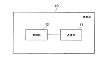
(移動通信端末の構成)
以下において、第1実施形態に係る移動通信端末の構成について、図面を参照しながら説明する。図2は、第1実施形態に係る通信端末装置10を示す図である。図2に示すように、通信端末装置10は、通信部11と、制御部12とを有する。
(Configuration of mobile communication terminal)
Hereinafter, the configuration of the mobile communication terminal according to the first embodiment will be described with reference to the drawings. FIG. 2 is a diagram illustrating the
通信部11は、NodeB20Aを介してRNC30Aと設定される無線接続を用いてUMTSと通信を行う。また、通信部11は、eNodeB30Bと設定される無線接続を用いてLTEと通信を行う。
The
第1実施形態では、通信部11は、RNC30A又はeNodeB30Bと設定される無線接続(例えば、RRC Connection)を設定するための制御信号を送信又は受信する。同様に、通信部11は、RNC30A又はeNodeB30Bと設定される無線接続(例えば、RRC Connection)を解放するための制御信号を送信又は受信する。
In 1st Embodiment, the
制御部12は、通信端末装置10を統括的に制御する。例えば、制御部12は、無線接続(例えば、RRC Connection)の設定又は解放を制御するための制御信号を送信するように通信部11を制御する。
The
第1実施形態では、制御部12は、第1通信システムに在圏しているときに、第2通信システムの通信リソースが確保される前に、第2通信システムへの遷移を希望する旨を示す制御信号を第1通信システムに送信するように通信部11を制御する。
In the first embodiment, when the
なお、「第2通信システムへの遷移の希望」は、第2通信システムの特定の通信セルへの遷移の希望であってもよい。特定の通信セルは、例えば、HeNB:Home eNoedeBが管理するセル、フェムトセル、接続が許容されるユーザを設定可能に構成されたCSG(Closed Subscriber Group)セルなどである。或いは、「第2通信システムへの遷移の希望」は、通信端末装置10が自律的に動作するケースにおける第2通信システムへの遷移の希望であってもよい。
The “hope to transition to the second communication system” may be a request to transition to a specific communication cell of the second communication system. The specific communication cell is, for example, a cell managed by HeNB: Home eNodeB, a femto cell, a CSG (Closed Subscriber Group) cell configured to be able to set a user allowed to connect. Alternatively, the “request for transition to the second communication system” may be a request for transition to the second communication system in a case where the
ここで、第2通信システムへの遷移を希望する旨を示す制御信号を送信する際に、通信端末装置10が遷移を希望する第2通信システムの通信セルのエリア近傍或いはエリア内に存在することを通信端末装置10又は第1通信システムが把握していることが好ましい。従って、第2通信システムからの制御信号(CPICH)の受信品質を通信端末装置10が事前に測定していることが好ましい。或いは、通信端末装置10が事前に接続した第2通信システムの通信セルの位置や周波数を通信端末装置10が記憶していることが好ましい(Finger Print)。また、通信端末装置10は、通信セルの位置や周波数を示す情報を制御信号に含めてもよい。
Here, when transmitting a control signal indicating that a transition to the second communication system is desired, the
ここで、第1通信システムがUMTSであり、第2通信システムがLTEであってもよいことに留意すべきである。又は、第1通信システムがLTEであり、第2通信システムがUMTSであってもよいことに留意すべきである。 Here, it should be noted that the first communication system may be UMTS and the second communication system may be LTE. Alternatively, it should be noted that the first communication system may be LTE and the second communication system may be UMTS.
(移動通信制御装置の構成)
以下において、第1実施形態に係る移動通信制御装置の構成について、図面を参照しながら説明する。図3は、第1実施形態に係る移動通信制御装置30を示す図である。図3に示すように、移動通信制御装置30は、通信部31と、制御部32とを有する。
(Configuration of mobile communication control device)
Hereinafter, the configuration of the mobile communication control apparatus according to the first embodiment will be described with reference to the drawings. FIG. 3 is a diagram illustrating the mobile
第1実施形態では、第1通信システムから第2通信システムに通信端末装置10が遷移するケースにおいて、第1通信システムにおいて通信リソースを制御する装置が移動通信制御装置30である。
In the first embodiment, in the case where the
上述したように、RNC30A及びeNodeB30Bは、移動通信制御装置30の一例である。従って、UMTSが第1通信システムである場合には、移動通信制御装置30はRNC30Aである。又は、LTEが第1通信システムである場合には、移動通信制御装置30はeNodeB30Bである。
As described above, the
通信部31は、通信端末装置10と設定される無線接続を用いて通信端末装置10と通信を行う。
The
第1実施形態では、通信部31は、通信端末装置10と設定される無線接続(例えば、RRC Connection)を設定するための制御信号を送信又は受信する。通信端末装置10と設定される無線接続(例えば、RRC Connection)を解放するための制御信号を送信又は受信する。
In the first embodiment, the
また、第1実施形態では、通信部31は、通信端末装置10が第1通信システムに在圏しているときに、第2通信システムの通信リソースが確保される前に、第2通信システムへの遷移を希望する旨を示す制御信号を通信端末装置10から受信する。
In the first embodiment, the
制御部32は、移動通信制御装置30を統括的に制御する。例えば、制御部32は、無線接続(例えば、RRC Connection)の設定又は解放を制御するための制御信号を送信するように通信部31を制御する。
The
第1実施形態では、制御部32は、第2通信システムへの遷移を希望する旨を示す制御信号を受信した場合に、第2通信システムの通信リソースが確保される前であっても、第1通信システムの通信リソースを解放する。
In the first embodiment, when the
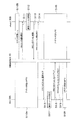
(移動通信システムの動作)
以下において、第1実施形態に係る移動通信システムの動作について、図面を参照しながら説明する。図4及び図5は、第1実施形態に係る移動通信システム100の動作を示すシーケンス図である。
(Operation of mobile communication system)
Hereinafter, the operation of the mobile communication system according to the first embodiment will be described with reference to the drawings. 4 and 5 are sequence diagrams showing operations of the
第1に、UMTSからLTEに通信端末装置10が遷移するケースについて、図4を参照しながら説明する。すなわち、図4では、UMTSが第1通信システムであり、LTEが第2通信システムである。
First, a case where the
図4に示すように、ステップ10Aにおいて、通信端末装置10は、UMTSにおいてコネクト状態である。ステップ10Bにおいて、通信端末装置10は、LTEにおいてアイドル状態である。
As shown in FIG. 4, in step 10A, the
ステップ11において、通信端末装置10は、RRCレイヤ(レイヤ3)のメッセージを用いて、LTEへの遷移を希望する旨を示す制御信号(Prefered to LTE)をRNC30Aに送信する。なお、この段階では、LTEの通信リソースが確保されていないことに留意すべきである。
In
ステップ12において、RNC30Aは、UMTSの通信リソースを解放する。
In
ステップ13において、RNC30Aは、RRCレイヤ(レイヤ3)のメッセージを用いて、RRCコネクション解放(RRC Connection Release)を通信端末装置10に送信する。
In step 13, the
ステップ14において、通信端末装置10は、RRCレイヤ(レイヤ3)のメッセージを用いて、RRCコネクション解放完了(RRC Connection Release Complete)をRNC30Aに送信する。
In step 14, the
ステップ15において、通信端末装置10は、UMTSにおいてアイドル状態に遷移する。すなわち、ステップ12〜ステップ14の処理によって、通信端末装置10は、UMTSにおいて、コネクト状態からアイドル状態に遷移する。
In step 15, the
ステップ16において、通信端末装置10は、RRCレイヤ(レイヤ3)のメッセージを用いて、RRCコネクション設定要求(RRC Connection Request)をeNodeB30Bに送信する。
In Step 16, the
なお、ステップ16の処理については、Redirection手順や再接続手順によって、通信端末装置10が自動的に行うことに留意すべきである。又は、ステップ16の処理において、NAS(Non Access Stratum) Recovery手順によって、通信端末装置10が自動的に行うことに留意すべきである(例えば、3GPP TS25.331 v9.0.0)。
It should be noted that the processing of step 16 is automatically performed by the
ステップ17において、eNodeB30Bは、LTEの通信リソースを設定する。
In step 17, the
ステップ18において、eNodeB30Bは、RRCレイヤ(レイヤ3)のメッセージを用いて、RRCコネクションセットアップ(RRC Connection Setup)を通信端末装置10に送信する。
In step 18, the
ステップ19において、通信端末装置10は、RRCレイヤ(レイヤ3)のメッセージを用いて、RRCコネクションセットアップ完了(RRC Connection Setup Complete)をeNodeB30Bに送信する。
In step 19, the
ステップ20において、通信端末装置10は、LTEにおいてコネクト状態に遷移する。すなわち、ステップ16〜ステップ19の処理によって、通信端末装置10は、LTEにおいて、アイドル状態からコネクト状態に遷移する。
In step 20, the
第2に、LTEからUMTSに通信端末装置10が遷移するケースについて、図5を参照しながら説明する。すなわち、図5では、LTEが第1通信システムであり、UMTSが第2通信システムである。
Secondly, a case where the
図5に示すように、ステップ110Aにおいて、通信端末装置10は、UMTSにおいてアイドル状態である。ステップ110Bにおいて、通信端末装置10は、LTEにおいてコネクト状態である。
As shown in FIG. 5, in
ステップ111において、通信端末装置10は、RRCレイヤ(レイヤ3)のメッセージを用いて、UMTSへの遷移を希望する旨を示す制御信号(Prefered to UMTS)をeNodeB30Bに送信する。なお、この段階では、UMTSの通信リソースが確保されていないことに留意すべきである。
In step 111, the
ステップ112において、eNodeB30Bは、LTEの通信リソースを解放する。
In step 112, the
ステップ113において、eNodeB30Bは、RRCレイヤ(レイヤ3)のメッセージを用いて、RRCコネクション解放(RRC Connection Release)を通信端末装置10に送信する。
In Step 113, the
ステップ114において、通信端末装置10は、RRCレイヤ(レイヤ3)のメッセージを用いて、RRCコネクション解放完了(RRC Connection Release Complete)をeNodeB30Bに送信する。
In step 114, the
ステップ115において、通信端末装置10は、LTEにおいてアイドル状態に遷移する。すなわち、ステップ112〜ステップ114の処理によって、通信端末装置10は、LTEにおいて、コネクト状態からアイドル状態に遷移する。
In step 115, the
ステップ116において、通信端末装置10は、RRCレイヤ(レイヤ3)のメッセージを用いて、RRCコネクション設定要求(RRC Connection Request)をRNC30Aに送信する。
In Step 116, the
なお、ステップ116の処理については、Redirection手順や再接続手順によって、通信端末装置10が自動的に行うことに留意すべきである。又は、ステップ116の処理において、NAS(Non Access Stratum) Recovery手順によって、通信端末装置10が自動的に行うことに留意すべきである。
It should be noted that the processing of step 116 is automatically performed by the
ステップ117において、RNC30Aは、UMTSの通信リソースを設定する。
In step 117, the
ステップ118において、RNC30Aは、RRCレイヤ(レイヤ3)のメッセージを用いて、RRCコネクションセットアップ(RRC Connection Setup)を通信端末装置10に送信する。
In Step 118, the
ステップ119において、通信端末装置10は、RRCレイヤ(レイヤ3)のメッセージを用いて、RRCコネクションセットアップ完了(RRC Connection Setup Complete)をRNC30Aに送信する。
In step 119, the
ステップ120において、通信端末装置10は、UMTSにおいてコネクト状態に遷移する。すなわち、ステップ116〜ステップ119の処理によって、通信端末装置10は、UMTSにおいて、アイドル状態からコネクト状態に遷移する。
In step 120, the
(作用及び効果)
第1実施形態では、第1通信システムは、第2通信システムの通信リソースが確保される前であっても、第2通信システムへの遷移を希望する旨を示す制御信号に応じて、第1通信システムの通信リソースを解放する。従って、第1通信システムの通信リソースが冗長に残存することが抑制される。
(Function and effect)
In the first embodiment, the first communication system receives the first signal in response to a control signal indicating that a transition to the second communication system is desired even before the communication resources of the second communication system are secured. Release communication resources of the communication system. Therefore, redundant communication resources of the first communication system are suppressed.
なお、第1通信システムから第2通信システムへの遷移において通信の瞬断が生じるが、Redirection手順、再接続手順、NAS Recovery手順によって、通信端末装置10と第2通信システムとの間の無線接続が設定されるため、通信が継続されることに留意すべきである。
In addition, although instantaneous communication interruption occurs in the transition from the first communication system to the second communication system, the wireless connection between the
[第2実施形態]
以下において、第2実施形態について、図面を参照しながら説明する。以下においては、第1実施形態との相違点について主として説明する。
[Second Embodiment]
Hereinafter, the second embodiment will be described with reference to the drawings. In the following, differences from the first embodiment will be mainly described.
第1実施形態において、通信端末装置10は、第1通信システムに在圏しているときに、第2通信システムの通信リソースが確保される前に、第2通信システムへの遷移を希望する旨を示す制御信号を第1通信システムに送信する。第1通信システム(移動通信制御装置30)は、第2通信システムの通信リソースが確保される前であっても、第2通信システムへの遷移を希望する旨を示す制御信号に応じて、第1通信システムの通信リソースを解放する。
In the first embodiment, when the
これに対して、第2実施形態では、通信端末装置10は、第2通信システムへの遷移を行う場合に、第2通信システムに遷移する前に第1通信システムに在圏していたことを示す制御信号を第2通信システムに送信する。第2通信システム(移動通信制御装置30)は、第2通信システムに遷移する前に第1通信システムに在圏していたことを示す制御信号に応じて、第1通信システムに対して、第1通信システムの通信リソースを解放する指示を送信する。
On the other hand, in the second embodiment, when the
第2実施形態では、第1通信システムから第2通信システムに通信端末装置10が遷移するケースにおいて、第2通信システムにおいて通信リソースを制御する装置が移動通信制御装置30である。
In the second embodiment, in the case where the
上述したように、RNC30A及びeNodeB30Bは、移動通信制御装置30の一例である。従って、UMTSが第2通信システムである場合には、移動通信制御装置30はRNC30Aである。又は、LTEが第2通信システムである場合には、移動通信制御装置30はeNodeB30Bである。
As described above, the
(移動通信システムの動作)
以下において、第2実施形態に係る移動通信システムの動作について、図面を参照しながら説明する。図6及び図7は、第2実施形態に係る移動通信システム100の動作を示すシーケンス図である。
(Operation of mobile communication system)
Hereinafter, the operation of the mobile communication system according to the second embodiment will be described with reference to the drawings. 6 and 7 are sequence diagrams showing the operation of the
第1に、UMTSからLTEに通信端末装置10が遷移するケースについて、図6を参照しながら説明する。すなわち、図6では、UMTSが第1通信システムであり、LTEが第2通信システムである。
First, a case where the
図6に示すように、ステップ210Aにおいて、通信端末装置10は、UMTSにおいてコネクト状態である。ステップ210Bにおいて、通信端末装置10は、LTEにおいてアイドル状態である。
As shown in FIG. 6, in step 210A, the
ステップ211において、通信端末装置10は、RRCレイヤ(レイヤ3)のメッセージを用いて、RRCコネクション設定要求(RRC Connection Request)をeNodeB30Bに送信する。
In step 211, the
ここで、通信端末装置10は、LTEに遷移する前に、UMTSに在圏していたことを示す制御信号を、RRCコネクション設定要求とともにeNodeB30Bに送信する。
Here, the
ステップ212において、eNodeB30Bは、LTEの通信リソースを設定する。
In step 212, the
ステップ213において、eNodeB30Bは、RRCレイヤ(レイヤ3)のメッセージを用いて、RRCコネクションセットアップ(RRC Connection Setup)を通信端末装置10に送信する。
In Step 213, the
ステップ214において、通信端末装置10は、RRCレイヤ(レイヤ3)のメッセージを用いて、RRCコネクションセットアップ完了(RRC Connection Setup Complete)をeNodeB30Bに送信する。
In step 214, the
ステップ215において、通信端末装置10は、LTEにおいてコネクト状態に遷移する。すなわち、ステップ211〜ステップ214の処理によって、通信端末装置10は、LTEにおいて、アイドル状態からコネクト状態に遷移する。
In step 215, the
ステップ216において、eNodeB30Bは、RNC30Aに対して、UMTSの通信リソースを解放する指示(通信リソース解放指示)を送信する。なお、通信リソース解放指示は、コアネットワーク50を経由して、eNodeB30BからRNC30Aに送信される。
In step 216, the
ステップ217において、RNC30Aは、UMTSの通信リソースを解放する。
In step 217, the
ステップ218において、通信端末装置10は、UMTSにおいてアイドル状態である。詳細には、通信端末装置10は、ステップ211の処理によって、UMTSにおいてアイドル状態に遷移していることに留意すべきである。
In step 218, the
第2に、LTEからUMTSに通信端末装置10が遷移するケースについて、図7を参照しながら説明する。すなわち、図7では、LTEが第1通信システムであり、UMTSが第2通信システムである。
Secondly, a case where the
図7に示すように、ステップ310Aにおいて、通信端末装置10は、UMTSにおいてアイドル状態である。ステップ310Bにおいて、通信端末装置10は、LTEにおいてコネクト状態である。
As shown in FIG. 7, in step 310A,
ステップ311において、通信端末装置10は、RRCレイヤ(レイヤ3)のメッセージを用いて、RRCコネクション設定要求(RRC Connection Request)をRNC30Aに送信する。
In step 311,
ここで、通信端末装置10は、UMTSに遷移する前に、LTEに在圏していたことを示す制御信号を、RRCコネクション設定要求とともにRNC30Aに送信する。
Here, the
ステップ312において、RNC30Aは、UMTSの通信リソースを設定する。
In step 312, the
ステップ313において、RNC30Aは、RRCレイヤ(レイヤ3)のメッセージを用いて、RRCコネクションセットアップ(RRC Connection Setup)を通信端末装置10に送信する。
In Step 313, the
ステップ314において、通信端末装置10は、RRCレイヤ(レイヤ3)のメッセージを用いて、RRCコネクションセットアップ完了(RRC Connection Setup Complete)をRNC30Aに送信する。
In step 314,
ステップ315において、通信端末装置10は、UMTSにおいてコネクト状態に遷移する。すなわち、ステップ311〜ステップ314の処理によって、通信端末装置10は、UMTSにおいて、アイドル状態からコネクト状態に遷移する。
In step 315, the
ステップ316において、RNC30Aは、eNodeB30Bに対して、LTEの通信リソースを解放する指示(通信リソース解放指示)を送信する。なお、通信リソース解放指示は、コアネットワーク50を経由して、RNC30AからeNodeB30Bに送信される。
In step 316, the
ステップ317において、eNodeB30Bは、LTEの通信リソースを解放する。
In step 317, the
ステップ318において、通信端末装置10は、LTEにおいてアイドル状態である。詳細には、通信端末装置10は、ステップ311の処理によって、LTEにおいてアイドル状態に遷移していることに留意すべきである。
In step 318, the
(作用及び効果)
第2実施形態では、第2通信システムは、第2通信システムに遷移する前に第1通信システムに在圏していたことを示す制御信号に応じて、第1通信システムに対して、第1通信システムの通信リソースを解放する指示を送信する。従って、第1通信システムの通信リソースが冗長に残存することが抑制される。
(Function and effect)
In the second embodiment, the second communication system has the first communication system with respect to the first communication system in response to a control signal indicating that the second communication system has been in the first communication system before transitioning to the second communication system. An instruction to release communication resources of the communication system is transmitted. Therefore, redundant communication resources of the first communication system are suppressed.
[その他の実施形態]
本発明は上述した実施形態によって説明したが、この開示の一部をなす論述及び図面は、この発明を限定するものであると理解すべきではない。この開示から当業者には様々な代替実施形態、実施例及び運用技術が明らかとなろう。
[Other Embodiments]
Although the present invention has been described with reference to the above-described embodiments, it should not be understood that the descriptions and drawings constituting a part of this disclosure limit the present invention. From this disclosure, various alternative embodiments, examples and operational techniques will be apparent to those skilled in the art.
上述した実施形態では、通信システムとして、UMTS及びLTEを例示したに過ぎない。従って、通信システムは、他の通信システム(例えば、GSM)であってもよい。 In the above-described embodiment, UMTS and LTE are merely exemplified as the communication system. Therefore, the communication system may be another communication system (for example, GSM).
10…通信端末装置、11…通信部、12…制御部、20A…NodeB、25A…エリア,25B…エリア、30…移動通信制御装置、30A…RNC、30…eNodeB、31…通信部、32…制御部、40A…SGSN/GGSN、40B…MME、50…コアネットワーク、100…移動通信システム
DESCRIPTION OF
Claims (4)
前記第2通信システムへの遷移を行う場合に、前記第2通信システムに遷移する前に前
記第1通信システムに在圏していたことを示す制御信号を前記第2通信システムに送信す
るように構成された送信部を備えることを特徴とする移動通信端末。
A mobile communication terminal configured to transition from a connected state in a first communication system to an idle state in a second communication system,
When a transition to the second communication system is performed, a control signal indicating that the user has been in the first communication system before the transition to the second communication system is transmitted to the second communication system. A mobile communication terminal comprising a configured transmission unit.
前記第2通信システムに設けられた移動通信制御装置であって、
前記移動通信端末が前記第2通信システムへの遷移を行う場合に、前記移動通信端末が
前記第2通信システムに遷移する前に前記第1通信システムに在圏していたことを示す制
御信号を前記移動通信端末から受信するように構成された受信部を備えることを特徴とする移動通信制御装置。
The mobile communication terminal configured to transition from the connected state in the first communication system to the idle state in the second communication system is configured to control communication resources for setting a wireless connection to be set,
A mobile communication control device provided in the second communication system,
When the mobile communication terminal makes a transition to the second communication system, a control signal indicating that the mobile communication terminal has been in the first communication system before making a transition to the second communication system A mobile communication control device comprising: a receiving unit configured to receive from the mobile communication terminal.
前記移動通信端末は、前記第2通信システムへの遷移を行う場合に、前記第2通信シス
テムに遷移する前に前記第1通信システムに在圏していたことを示す制御信号を前記第2
通信システムに送信するように構成されることを特徴とする移動通信システム。
A mobile communication system comprising a first communication system, a second communication system, and a mobile communication terminal configured to transition from a connected state in the first communication system to an idle state in the second communication system,
When the mobile communication terminal makes a transition to the second communication system, the mobile communication terminal sends a control signal indicating that the mobile communication terminal has been in the first communication system before making the transition to the second communication system.
A mobile communication system configured to transmit to a communication system.
前記移動通信端末が、前記第2通信システムへの遷移を行う場合に、前記第2通信シス
テムに遷移する前に前記第1通信システムに在圏していたことを示す制御信号を前記第2
通信システムに送信するステップを備えることを特徴とする移動通信方法。 Applied to a mobile communication system having a first communication system, a second communication system, and a mobile communication terminal configured to transition from a connected state in the first communication system to an idle state in the second communication system A mobile communication method,
When the mobile communication terminal makes a transition to the second communication system, a control signal indicating that the mobile communication terminal has been in the first communication system before changing to the second communication system is sent to the second communication system.
A mobile communication method comprising a step of transmitting to a communication system.
Priority Applications (8)
| Application Number | Priority Date | Filing Date | Title |
|---|---|---|---|
| JP2009241908A JP5150601B2 (en) | 2009-10-20 | 2009-10-20 | Mobile communication terminal, mobile communication control apparatus, mobile communication system, and mobile communication method |
| KR1020127010931A KR101406088B1 (en) | 2009-10-20 | 2010-10-20 | Mobile communication terminal, mobile communication control device, mobile communication system, and mobile communication method |
| RU2012119264/07A RU2526532C2 (en) | 2009-10-20 | 2010-10-20 | Terminal, controller, system and mobile communication method |
| CA2778282A CA2778282A1 (en) | 2009-10-20 | 2010-10-20 | Mobile communication terminal, mobile communication controller, mobile communication system, and mobile communication method |
| CN201080047520.8A CN102598788B (en) | 2009-10-20 | 2010-10-20 | Mobile communication terminal, mobile communication control device, mobile communication system and method for mobile communication |
| EP10824978.0A EP2493242B1 (en) | 2009-10-20 | 2010-10-20 | Mobile communication control device, mobile communication system, and mobile communication method |
| PCT/JP2010/068484 WO2011049129A1 (en) | 2009-10-20 | 2010-10-20 | Mobile communication terminal, mobile communication control device, mobile communication system, and mobile communication method |
| US13/503,036 US20120252456A1 (en) | 2009-10-20 | 2010-10-20 | Mobile communication terminal, mobile communication controller, mobile communication system, and mobile communication method |
Applications Claiming Priority (1)
| Application Number | Priority Date | Filing Date | Title |
|---|---|---|---|
| JP2009241908A JP5150601B2 (en) | 2009-10-20 | 2009-10-20 | Mobile communication terminal, mobile communication control apparatus, mobile communication system, and mobile communication method |
Publications (3)
| Publication Number | Publication Date |
|---|---|
| JP2011091515A JP2011091515A (en) | 2011-05-06 |
| JP2011091515A5 JP2011091515A5 (en) | 2012-05-17 |
| JP5150601B2 true JP5150601B2 (en) | 2013-02-20 |
Family
ID=43900352
Family Applications (1)
| Application Number | Title | Priority Date | Filing Date |
|---|---|---|---|
| JP2009241908A Active JP5150601B2 (en) | 2009-10-20 | 2009-10-20 | Mobile communication terminal, mobile communication control apparatus, mobile communication system, and mobile communication method |
Country Status (8)
| Country | Link |
|---|---|
| US (1) | US20120252456A1 (en) |
| EP (1) | EP2493242B1 (en) |
| JP (1) | JP5150601B2 (en) |
| KR (1) | KR101406088B1 (en) |
| CN (1) | CN102598788B (en) |
| CA (1) | CA2778282A1 (en) |
| RU (1) | RU2526532C2 (en) |
| WO (1) | WO2011049129A1 (en) |
Families Citing this family (2)
| Publication number | Priority date | Publication date | Assignee | Title |
|---|---|---|---|---|
| BR112014006486A2 (en) | 2011-09-27 | 2017-03-28 | Nec Corp | input port and control device, and communication control methods for same |
| US20130244655A1 (en) * | 2012-02-29 | 2013-09-19 | Qualcomm Incorporated | Methods and devices for facilitating fast cell reselection at call release |
Family Cites Families (18)
| Publication number | Priority date | Publication date | Assignee | Title |
|---|---|---|---|---|
| GB2389752B (en) * | 1999-05-28 | 2004-02-25 | Nec Corp | Mobile telecommunications system |
| FI109071B (en) * | 2000-01-17 | 2002-05-15 | Nokia Corp | A signaling |
| US7313628B2 (en) * | 2001-06-28 | 2007-12-25 | Nokia, Inc. | Protocol to determine optimal target access routers for seamless IP-level handover |
| US7050828B2 (en) * | 2002-09-23 | 2006-05-23 | Telefonaktiebolaget Lm Ericsson (Publ) | Inter-system monitor function |
| KR100703264B1 (en) * | 2003-08-29 | 2007-04-03 | 삼성전자주식회사 | Method and system for providing voice and data services in mobile communication system overlaped by various access networks |
| US20080132236A1 (en) * | 2005-03-07 | 2008-06-05 | Shinji Kiribayashi | Mobile Communication Terminal and Method for Notifying Handover Operation |
| GB0514438D0 (en) | 2005-07-15 | 2005-08-17 | Ip Access Ltd | Cellular radio tellecommunication handover system |
| US8260291B2 (en) * | 2005-12-26 | 2012-09-04 | Htc Corporation | Method for handling periodic PLMN search in RRC connected mode in UMTS system |
| KR20080109892A (en) * | 2006-03-09 | 2008-12-17 | 인터디지탈 테크날러지 코포레이션 | Wireless communication method and system for performing handover between two radio access technologies |
| CN101047977A (en) * | 2006-03-27 | 2007-10-03 | 华为技术有限公司 | Radio communication system and method and call method used in the system |
| CN100456891C (en) * | 2006-07-19 | 2009-01-28 | 华为技术有限公司 | Method for carrying out switching on activated state access terminal |
| JP4916277B2 (en) * | 2006-10-31 | 2012-04-11 | 株式会社エヌ・ティ・ティ・ドコモ | User device and method used in user device |
| ES2391413T3 (en) * | 2007-04-12 | 2012-11-26 | Alcatel Lucent | Procedure for mobility management in a system architecture that supports mobility between different access systems |
| WO2009018164A2 (en) * | 2007-07-27 | 2009-02-05 | Interdigital Patent Holdings, Inc. | Method and apparatus for handling mobility between non-3gpp to 3gpp networks |
| JP5184005B2 (en) * | 2007-08-30 | 2013-04-17 | 京セラ株式会社 | Mobile terminal device |
| US8054802B2 (en) | 2007-10-29 | 2011-11-08 | Alcatel Lucent | Hand-off trigger at access technology borders |
| EP2079253A1 (en) * | 2008-01-09 | 2009-07-15 | Panasonic Corporation | Non-3GPP to 3GPP network handover optimizations |
| WO2010085208A1 (en) * | 2009-01-23 | 2010-07-29 | Telefonaktiebolaget L M Ericsson (Publ) | Configuring relations between cells in different radio access networks |
-
2009
- 2009-10-20 JP JP2009241908A patent/JP5150601B2/en active Active
-
2010
- 2010-10-20 CN CN201080047520.8A patent/CN102598788B/en active Active
- 2010-10-20 WO PCT/JP2010/068484 patent/WO2011049129A1/en active Application Filing
- 2010-10-20 EP EP10824978.0A patent/EP2493242B1/en active Active
- 2010-10-20 RU RU2012119264/07A patent/RU2526532C2/en active
- 2010-10-20 US US13/503,036 patent/US20120252456A1/en not_active Abandoned
- 2010-10-20 CA CA2778282A patent/CA2778282A1/en not_active Abandoned
- 2010-10-20 KR KR1020127010931A patent/KR101406088B1/en active IP Right Grant
Also Published As
| Publication number | Publication date |
|---|---|
| JP2011091515A (en) | 2011-05-06 |
| EP2493242A4 (en) | 2016-12-07 |
| CN102598788A (en) | 2012-07-18 |
| RU2012119264A (en) | 2013-11-27 |
| KR20120076427A (en) | 2012-07-09 |
| US20120252456A1 (en) | 2012-10-04 |
| CN102598788B (en) | 2016-10-12 |
| EP2493242B1 (en) | 2018-12-12 |
| KR101406088B1 (en) | 2014-06-11 |
| CA2778282A1 (en) | 2011-04-28 |
| RU2526532C2 (en) | 2014-08-27 |
| EP2493242A1 (en) | 2012-08-29 |
| WO2011049129A1 (en) | 2011-04-28 |
Similar Documents
| Publication | Publication Date | Title |
|---|---|---|
| JP7279773B2 (en) | Wireless terminal and method | |
| WO2019196783A1 (en) | Handling qos flow without a mapping data radio bearer | |
| JP6610686B2 (en) | Wireless terminal, wireless station, wireless communication system, and methods thereof | |
| EP3979707B1 (en) | Method for initiating user plane path modification in a communications system | |
| CN109997408B (en) | Core network awareness of user equipment UE status | |
| US10015718B2 (en) | Method, apparatus, and system for routing user plane data in mobile network | |
| WO2018128020A1 (en) | Base station, wireless terminal, methods therefor, and non-temporary computer-readable medium | |
| JP6376137B2 (en) | Wireless communication system, base station apparatus, and wireless terminal | |
| US9320075B2 (en) | Method, system and transmission distribution network element for indicating data-distribution | |
| EP3595359B1 (en) | Handover apparatus and method | |
| JP7147830B2 (en) | Wireless terminal and method | |
| JP2014517652A (en) | Traffic offload through local network | |
| US20180220302A1 (en) | Access control method, user equipment, and network device | |
| WO2016061785A1 (en) | Radio resource control (rrc) connection method, reconnection method, and apparatus | |
| US8498236B2 (en) | Mobile communication system | |
| AU2021308253A1 (en) | Communication method and communication apparatus | |
| EP2636277A1 (en) | Improved quality of service control | |
| WO2011076063A1 (en) | Method, device, and system for managing local internet protocol access or selected internet protocol traffic offload | |
| WO2020224597A1 (en) | Pdn connection supports interworking to 5gs | |
| JP5150601B2 (en) | Mobile communication terminal, mobile communication control apparatus, mobile communication system, and mobile communication method | |
| EP3324677B1 (en) | Network access change for a terminal from an access through a relay terminal to a direct access | |
| WO2021241663A1 (en) | Communication control method and user equipment | |
| WO2017166291A1 (en) | Communication method, terminal, base station, and mobility management equipment | |
| JP2007536782A (en) | Mobile communication system and method for switching services between an asynchronous network and a synchronous network | |
| WO2011060687A1 (en) | Method and system for base station de-registration |
Legal Events
| Date | Code | Title | Description |
|---|---|---|---|
| A621 | Written request for application examination |
Free format text: JAPANESE INTERMEDIATE CODE: A621 Effective date: 20110331 |
|
| A521 | Request for written amendment filed |
Free format text: JAPANESE INTERMEDIATE CODE: A523 Effective date: 20120323 |
|
| A131 | Notification of reasons for refusal |
Free format text: JAPANESE INTERMEDIATE CODE: A131 Effective date: 20120529 |
|
| TRDD | Decision of grant or rejection written | ||
| A01 | Written decision to grant a patent or to grant a registration (utility model) |
Free format text: JAPANESE INTERMEDIATE CODE: A01 Effective date: 20121113 |
|
| A61 | First payment of annual fees (during grant procedure) |
Free format text: JAPANESE INTERMEDIATE CODE: A61 Effective date: 20121203 |
|
| R150 | Certificate of patent or registration of utility model |
Ref document number: 5150601 Country of ref document: JP Free format text: JAPANESE INTERMEDIATE CODE: R150 Free format text: JAPANESE INTERMEDIATE CODE: R150 |
|
| FPAY | Renewal fee payment (event date is renewal date of database) |
Free format text: PAYMENT UNTIL: 20151207 Year of fee payment: 3 |
|
| R250 | Receipt of annual fees |
Free format text: JAPANESE INTERMEDIATE CODE: R250 |
|
| R250 | Receipt of annual fees |
Free format text: JAPANESE INTERMEDIATE CODE: R250 |
|
| R250 | Receipt of annual fees |
Free format text: JAPANESE INTERMEDIATE CODE: R250 |
|
| R250 | Receipt of annual fees |
Free format text: JAPANESE INTERMEDIATE CODE: R250 |
|
| R250 | Receipt of annual fees |
Free format text: JAPANESE INTERMEDIATE CODE: R250 |
|
| R250 | Receipt of annual fees |
Free format text: JAPANESE INTERMEDIATE CODE: R250 |
|
| R250 | Receipt of annual fees |
Free format text: JAPANESE INTERMEDIATE CODE: R250 |
|
| R250 | Receipt of annual fees |
Free format text: JAPANESE INTERMEDIATE CODE: R250 |
|
| R250 | Receipt of annual fees |
Free format text: JAPANESE INTERMEDIATE CODE: R250 |