JP5147879B2 - Optical disc, optical disc apparatus, information recording method, and information reproducing method - Google Patents
Optical disc, optical disc apparatus, information recording method, and information reproducing method Download PDFInfo
- Publication number
- JP5147879B2 JP5147879B2 JP2010048581A JP2010048581A JP5147879B2 JP 5147879 B2 JP5147879 B2 JP 5147879B2 JP 2010048581 A JP2010048581 A JP 2010048581A JP 2010048581 A JP2010048581 A JP 2010048581A JP 5147879 B2 JP5147879 B2 JP 5147879B2
- Authority
- JP
- Japan
- Prior art keywords
- data recording
- layer
- recording density
- recording
- information
- Prior art date
- Legal status (The legal status is an assumption and is not a legal conclusion. Google has not performed a legal analysis and makes no representation as to the accuracy of the status listed.)
- Expired - Fee Related
Links
Images


Classifications
-
- G—PHYSICS
- G11—INFORMATION STORAGE
- G11B—INFORMATION STORAGE BASED ON RELATIVE MOVEMENT BETWEEN RECORD CARRIER AND TRANSDUCER
- G11B20/00—Signal processing not specific to the method of recording or reproducing; Circuits therefor
- G11B20/10—Digital recording or reproducing
- G11B20/12—Formatting, e.g. arrangement of data block or words on the record carriers
- G11B20/1217—Formatting, e.g. arrangement of data block or words on the record carriers on discs
-
- G—PHYSICS
- G11—INFORMATION STORAGE
- G11B—INFORMATION STORAGE BASED ON RELATIVE MOVEMENT BETWEEN RECORD CARRIER AND TRANSDUCER
- G11B20/00—Signal processing not specific to the method of recording or reproducing; Circuits therefor
- G11B20/10—Digital recording or reproducing
- G11B20/12—Formatting, e.g. arrangement of data block or words on the record carriers
- G11B20/1262—Formatting, e.g. arrangement of data block or words on the record carriers with more than one format/standard, e.g. conversion from CD-audio format to R-DAT format
-
- G—PHYSICS
- G11—INFORMATION STORAGE
- G11B—INFORMATION STORAGE BASED ON RELATIVE MOVEMENT BETWEEN RECORD CARRIER AND TRANSDUCER
- G11B7/00—Recording or reproducing by optical means, e.g. recording using a thermal beam of optical radiation by modifying optical properties or the physical structure, reproducing using an optical beam at lower power by sensing optical properties; Record carriers therefor
- G11B7/007—Arrangement of the information on the record carrier, e.g. form of tracks, actual track shape, e.g. wobbled, or cross-section, e.g. v-shaped; Sequential information structures, e.g. sectoring or header formats within a track
- G11B7/00736—Auxiliary data, e.g. lead-in, lead-out, Power Calibration Area [PCA], Burst Cutting Area [BCA], control information
-
- G—PHYSICS
- G11—INFORMATION STORAGE
- G11B—INFORMATION STORAGE BASED ON RELATIVE MOVEMENT BETWEEN RECORD CARRIER AND TRANSDUCER
- G11B7/00—Recording or reproducing by optical means, e.g. recording using a thermal beam of optical radiation by modifying optical properties or the physical structure, reproducing using an optical beam at lower power by sensing optical properties; Record carriers therefor
- G11B7/007—Arrangement of the information on the record carrier, e.g. form of tracks, actual track shape, e.g. wobbled, or cross-section, e.g. v-shaped; Sequential information structures, e.g. sectoring or header formats within a track
- G11B7/0079—Zoned data area, e.g. having different data structures or formats for the user data within data layer, Zone Constant Linear Velocity [ZCLV], Zone Constant Angular Velocity [ZCAV], carriers with RAM and ROM areas
-
- G—PHYSICS
- G11—INFORMATION STORAGE
- G11B—INFORMATION STORAGE BASED ON RELATIVE MOVEMENT BETWEEN RECORD CARRIER AND TRANSDUCER
- G11B7/00—Recording or reproducing by optical means, e.g. recording using a thermal beam of optical radiation by modifying optical properties or the physical structure, reproducing using an optical beam at lower power by sensing optical properties; Record carriers therefor
- G11B7/24—Record carriers characterised by shape, structure or physical properties, or by the selection of the material
- G11B7/2403—Layers; Shape, structure or physical properties thereof
- G11B7/24035—Recording layers
- G11B7/24038—Multiple laminated recording layers
- G11B7/24041—Multiple laminated recording layers with different recording characteristics
-
- G—PHYSICS
- G11—INFORMATION STORAGE
- G11B—INFORMATION STORAGE BASED ON RELATIVE MOVEMENT BETWEEN RECORD CARRIER AND TRANSDUCER
- G11B20/00—Signal processing not specific to the method of recording or reproducing; Circuits therefor
- G11B20/10—Digital recording or reproducing
- G11B20/12—Formatting, e.g. arrangement of data block or words on the record carriers
- G11B20/1217—Formatting, e.g. arrangement of data block or words on the record carriers on discs
- G11B2020/1218—Formatting, e.g. arrangement of data block or words on the record carriers on discs wherein the formatting concerns a specific area of the disc
- G11B2020/122—Burst cutting area [BCA]
-
- G—PHYSICS
- G11—INFORMATION STORAGE
- G11B—INFORMATION STORAGE BASED ON RELATIVE MOVEMENT BETWEEN RECORD CARRIER AND TRANSDUCER
- G11B20/00—Signal processing not specific to the method of recording or reproducing; Circuits therefor
- G11B20/10—Digital recording or reproducing
- G11B20/12—Formatting, e.g. arrangement of data block or words on the record carriers
- G11B20/1217—Formatting, e.g. arrangement of data block or words on the record carriers on discs
- G11B2020/1218—Formatting, e.g. arrangement of data block or words on the record carriers on discs wherein the formatting concerns a specific area of the disc
- G11B2020/1227—Formatting, e.g. arrangement of data block or words on the record carriers on discs wherein the formatting concerns a specific area of the disc one layer of multilayer disc
-
- G—PHYSICS
- G11—INFORMATION STORAGE
- G11B—INFORMATION STORAGE BASED ON RELATIVE MOVEMENT BETWEEN RECORD CARRIER AND TRANSDUCER
- G11B20/00—Signal processing not specific to the method of recording or reproducing; Circuits therefor
- G11B20/10—Digital recording or reproducing
- G11B20/12—Formatting, e.g. arrangement of data block or words on the record carriers
- G11B2020/1264—Formatting, e.g. arrangement of data block or words on the record carriers wherein the formatting concerns a specific kind of data
- G11B2020/1265—Control data, system data or management information, i.e. data used to access or process user data
- G11B2020/1278—Physical format specifications of the record carrier, e.g. compliance with a specific standard, recording density, number of layers, start of data zone or lead-out
-
- G—PHYSICS
- G11—INFORMATION STORAGE
- G11B—INFORMATION STORAGE BASED ON RELATIVE MOVEMENT BETWEEN RECORD CARRIER AND TRANSDUCER
- G11B2220/00—Record carriers by type
- G11B2220/20—Disc-shaped record carriers
- G11B2220/23—Disc-shaped record carriers characterised in that the disc has a specific layer structure
- G11B2220/235—Multilayer discs, i.e. multiple recording layers accessed from the same side
-
- G—PHYSICS
- G11—INFORMATION STORAGE
- G11B—INFORMATION STORAGE BASED ON RELATIVE MOVEMENT BETWEEN RECORD CARRIER AND TRANSDUCER
- G11B2220/00—Record carriers by type
- G11B2220/20—Disc-shaped record carriers
- G11B2220/25—Disc-shaped record carriers characterised in that the disc is based on a specific recording technology
- G11B2220/2537—Optical discs
- G11B2220/2541—Blu-ray discs; Blue laser DVR discs
-
- G—PHYSICS
- G11—INFORMATION STORAGE
- G11B—INFORMATION STORAGE BASED ON RELATIVE MOVEMENT BETWEEN RECORD CARRIER AND TRANSDUCER
- G11B2220/00—Record carriers by type
- G11B2220/20—Disc-shaped record carriers
- G11B2220/25—Disc-shaped record carriers characterised in that the disc is based on a specific recording technology
- G11B2220/2537—Optical discs
- G11B2220/2583—Optical discs wherein two standards are used on a single disc, e.g. one DVD section and one CD section
Description
本発明は、複数種類のデータ記録密度で情報を記録するための光ディスク、光ディスク記録再生装置および情報記録再生方法に関するものである。 The present invention relates to an optical disc, an optical disc recording / reproducing apparatus, and an information recording / reproducing method for recording information at a plurality of types of data recording densities.
高密度大容量記録可能な光ディスクでは、記録層を多層化することで更なる大容量化が進められている。例えばブルーレイディスク(BD)では、1枚のディスクに100GBの情報を記録するために、標準のデータ記録密度である25GB/layerの4層化と、さらに高密度化した33GB/layerの3層化などのアプローチがなされている。このように、データ記録密度を始め記録フォーマットの異なる光ディスクが出現すると、これらを識別しそのフォーマットに対応して記録再生を行う光ディスク装置が必要になる。 In an optical disc capable of high-density and large-capacity recording, the capacity is further increased by increasing the number of recording layers. For example, in Blu-ray Disc (BD), in order to record 100 GB of information on a single disc, the standard data recording density of 25 GB / layer is increased to 4 layers, and 33 GB / layer is further increased in density to 3 layers. Such an approach has been made. As described above, when optical disks having different recording formats such as data recording density appear, an optical disk apparatus that identifies them and performs recording and reproduction in accordance with the format is required.
これに関連する技術として、例えば特許文献1には、ディスクの種類に応じて光学系(開口数、NA)を切り替え、さらにこれに連動して信号処理系の特性を変更する構成が開示されている。また特許文献2には、1枚のディスクが異なるフォーマットで記録された複数の記録層を持つ場合、各記録層のフォーマットを認識するために、リードイン領域に複数の記録層のフォーマット情報を記録する構造が開示されている。
As a technology related to this, for example,
前記したように、BD多層ディスクの場合、従来の標準密度(25GB/layer)と高密度(33GB/layer)の2種類のデータ記録密度が候補とされている。この場合、いずれのフォーマットでも青色レーザーの波長は405nm、開口数(NA)は0.85を用いるので、ディスク面の反射率などによるフォーマット判別は困難になる。よって、前記特許文献1に記載の技術ではディスクを識別して再生することができない。
As described above, in the case of a BD multi-layer disc, two types of data recording densities of the conventional standard density (25 GB / layer) and high density (33 GB / layer) are candidates. In this case, since the wavelength of the blue laser is 405 nm and the numerical aperture (NA) is 0.85 in any format, it is difficult to determine the format based on the reflectivity of the disk surface. Therefore, the technique described in
特許文献2では、2種類のフォーマット(HD_DVDとDVD)が混在する多層ディスクの識別を行うため、リードインエリア(System/Data Read in Area)やBCA(Burst Cutting Area)に各層のフォーマット情報(レイヤーフォーマットテーブル)を記録しておくものである。しかしながら、次の点で不都合が生じる。
In
(1)リードインエリアの場合、フォーマット情報自身が、そのリードインエリアが属する層のフォーマットに依存して記録されている。リードンエリアから情報を読み出すためにはそのフォーマットが既知でなければならないが、層とフォーマットの対応が決められていない場合、リードンエリアの情報の読み出しに失敗することが予想される。 (1) In the case of a lead-in area, the format information itself is recorded depending on the format of the layer to which the lead-in area belongs. In order to read information from the leadon area, the format must be known. However, if the correspondence between the layer and the format is not determined, it is expected that reading of the information in the leadon area will fail.
(2)フォーマット情報を記録する領域(ディスク管理情報領域)が高密度フォーマットで記録される領域であると、従来の標準密度(=低密度)にのみ対応した装置では読み出し不能となりディスクの判別が不可能である。 (2) If the area for recording the format information (disk management information area) is an area for recording in the high density format, the conventional apparatus corresponding only to the standard density (= low density) becomes unreadable and disc discrimination is possible. Impossible.
(3)多層ディスクの場合、各層のフォーマットとともに層の記録可否情報を合わせて管理することが望ましい。その場合、ディスク製造後にフォーマット情報を記録できることが必要となる。特許文献2に示されるリードインエリアやBCAは、ディスク製造時に作成されるものであって、製造後に記録することはできない。
(3) In the case of a multilayer disc, it is desirable to manage the recordability information of each layer together with the format of each layer. In that case, it is necessary to be able to record the format information after manufacturing the disc. The lead-in area and BCA shown in
本発明の目的は、複数種類のデータ記録密度で記録されるディスクにおいて、そのディスク管理情報を誤りなく容易に読み出し可能な光ディスク、光ディスク記録再生装置および情報記録再生方法を提供することである。 An object of the present invention is to provide an optical disc, an optical disc recording / reproducing apparatus, and an information recording / reproducing method capable of easily reading out disc management information without error in a disc recorded at a plurality of types of data recording densities.
本発明は、所定の記録密度で情報を記録する光ディスクにおいて、情報を記録するためのデータ記録領域と、データ記録領域におけるデータ記録密度の情報を含むディスク管理情報を記録するための管理情報記録領域を有し、管理情報記録領域には、データ記録領域のデータ記録密度に依存しない特定のフォーマットにてディスク管理情報を記録する。 The present invention relates to a data recording area for recording information in an optical disk for recording information at a predetermined recording density, and a management information recording area for recording disk management information including information on the data recording density in the data recording area In the management information recording area, disc management information is recorded in a specific format independent of the data recording density of the data recording area.
本発明は、複数の記録密度で情報を記録可能な光ディスクにおいて、同一面内に分割して配置され、互いに異なるデータ記録密度にて情報を記録する複数のデータ記録領域と、複数のデータ記録領域における各々のデータ記録密度と各データ記録領域の境界位置の情報を含むディスク管理情報を記録するための管理情報記録領域を有し、管理情報記録領域には、複数のデータ記録領域の各々のデータ記録密度に依存しない特定のフォーマットにてディスク管理情報を記録する。 The present invention relates to an optical disc capable of recording information at a plurality of recording densities, divided into the same plane, and a plurality of data recording areas for recording information at different data recording densities, and a plurality of data recording areas Management information recording area for recording disc management information including information on each data recording density and boundary position of each data recording area, and the management information recording area includes data of each of the plurality of data recording areas. Disc management information is recorded in a specific format independent of the recording density.
本発明は、複数の記録層を有し複数の記録密度で情報を記録可能な光ディスクにおいて、記録層毎に異なるデータ記録密度にて情報を記録する複数のデータ記録領域と、各記録層のデータ記録領域における各々のデータ記録密度の情報を含むディスク管理情報を記録するための管理情報記録領域を有し、管理情報記録領域には、複数のデータ記録領域の各々のデータ記録密度に依存しない特定のフォーマットにてディスク管理情報を記録する。 The present invention relates to an optical disc having a plurality of recording layers and capable of recording information at a plurality of recording densities, a plurality of data recording areas for recording information at different data recording densities for each recording layer, and data of each recording layer It has a management information recording area for recording disc management information including information on each data recording density in the recording area, and the management information recording area is specified not depending on the data recording density of each of the plurality of data recording areas. Record the disc management information in the format.
本発明は、複数の記録層を有し複数の記録密度で情報を記録可能な光ディスクにおいて、記録層毎に異なるデータ記録密度にて情報を記録する複数のデータ記録領域と、複数のデータ記録領域における各々のデータ記録密度を含むディスク管理情報を記録するための管理情報記録領域を有し、管理情報記録領域は、複数のデータ記録領域の中でデータ記録密度が標準密度であるデータ記録領域内の一部領域に配置し、ディスク管理情報を該領域のデータ記録密度のフォーマットにて記録する。 The present invention relates to an optical disc having a plurality of recording layers and capable of recording information at a plurality of recording densities, a plurality of data recording areas for recording information at different data recording densities for each recording layer, and a plurality of data recording areas A management information recording area for recording disc management information including each data recording density in the data recording area, the data recording density being a standard density among the plurality of data recording areas The disk management information is recorded in the format of the data recording density of the area.
本発明は、光ディスクのデータ記録領域に情報を記録または再生する光ディスク記録再生装置において、光ディスクの管理情報記録領域には、データ記録領域のデータ記録密度に依存しない特定のフォーマットにてデータ記録領域のデータ記録密度の情報を含むディスク管理情報が記録されているものであって、光ディスクを回転させるスピンドルモータと、光ディスクの管理情報記録領域からディスク管理情報を読み出すとともに、光ディスクのデータ記録領域に情報を記録または再生する光ヘッドと、光ヘッドに供給する記録信号または光ヘッドからの再生信号を処理する記録再生処理部と、光ヘッドにより読み出したディスク管理情報から目標のデータ記録領域のデータ記録密度または間接的にデータ記録密度と関連を持つ情報を判定する記録密度判定回路と、を備え、記録再生処理部は、記録密度判定回路により判定したデータ記録密度に応じて、記録再生処理条件を選択して設定するもしくは適切な方法で以降の動作を停止する。例えばディスク層数とデータ記録密度が一対一に対応をする場合は、ディスク層数により記録再生条件の選択、もしくは適切な方法で以降の動作を停止する動作を実施する。また、その他の例としてディスクの記録容量もデータ記録密度と関連する情報となる場合があり、その場合はディスク記録容量により記録再生条件の選択、もしくは適切な方法で以降の動作を停止する動作を実施する。 The present invention relates to an optical disc recording / reproducing apparatus for recording or reproducing information in a data recording area of an optical disc, wherein the management information recording area of the optical disc has a data recording area in a specific format independent of the data recording density of the data recording area. Disc management information including data recording density information is recorded. The spindle motor that rotates the optical disc and the disc management information are read from the management information recording region of the optical disc, and the information is stored in the data recording region of the optical disc. An optical head for recording or reproducing, a recording / reproducing processing unit for processing a recording signal supplied to the optical head or a reproducing signal from the optical head, and a data recording density or Determine information indirectly related to data recording density A recording density determination circuit, and the recording / reproduction processing unit selects and sets the recording / reproduction processing conditions according to the data recording density determined by the recording density determination circuit, or stops the subsequent operation by an appropriate method. To do. For example, when there is a one-to-one correspondence between the number of disk layers and the data recording density, recording / reproduction conditions are selected according to the number of disk layers, or an operation for stopping subsequent operations is performed by an appropriate method. As another example, the recording capacity of the disc may also be information related to the data recording density. In this case, the recording / reproducing condition is selected depending on the disc recording capacity, or the operation of stopping the subsequent operation by an appropriate method is performed. carry out.
本発明は、光ディスクのデータ記録領域に情報を記録または再生する情報記録再生方法において、光ディスクの管理情報記録領域には、データ記録領域のデータ記録密度に依存しない特定のフォーマットにてデータ記録領域のデータ記録密度の情報を含むディスク管理情報が記録されており、前記特定のフォーマットに従ってディスク管理情報を再生するための再生条件を設定するステップと、光ディスクの管理情報記録領域からディスク管理情報を読み出すステップと、読み出したディスク管理情報からデータ記録領域のデータ記録密度または間接的にデータ記録密度と関連を持つ情報を判定するステップと、判定したデータ記録密度に応じて記録再生処理条件を選択して設定するステップと、設定した記録再生処理条件にてデータ記録領域にて情報を記録または再生するステップ、もしくは適切な方法で以降の動作を停止するステップとを備える。 The present invention relates to an information recording / reproducing method for recording or reproducing information in a data recording area of an optical disc, wherein the management information recording area of the optical disc has a data recording area in a specific format independent of the data recording density of the data recording area. Disc management information including data recording density information is recorded, setting reproduction conditions for reproducing the disc management information according to the specific format, and reading the disc management information from the management information recording area of the optical disc Determining the data recording density of the data recording area or information indirectly related to the data recording density from the read disc management information, and selecting and setting the recording / reproducing processing conditions according to the determined data recording density And the data recording area according to the set recording / playback processing conditions. At and a step of stopping the subsequent operation information step for recording or reproducing, or in a suitable manner.
また本発明は、光ディスクのデータ記録領域に情報を記録または再生する情報記録再生方法において、光ディスクの管理情報記録領域には、データ記録領域のデータ記録密度に依存しない特定のフォーマットにてデータ記録領域のデータ記録密度の情報を含むディスク管理情報を記録することにより、このディスクの記録、再生に対応していない既存ドライブに前記ディスクが装着された時に、既存ドライブが正しい処理(例えば安全に機能を停止する、ディスクを排出する)を行うために必要なディスク判別情報を既存ドライブが取得できるようにするための手段を提供する。 The present invention also relates to an information recording / reproducing method for recording or reproducing information in a data recording area of an optical disc, wherein the management information recording area of the optical disc has a data recording area in a specific format independent of the data recording density of the data recording area By recording disc management information including information on the data recording density of the disc, when the disc is loaded into an existing drive that does not support recording and playback of this disc, the existing drive is correctly processed (for example, functions safely). Provided is a means for enabling an existing drive to acquire disc discrimination information necessary for performing (stop, eject disc).
本発明によれば、複数種類のデータ記録密度で記録される光ディスクに対し、そのディスク管理情報を誤りなく容易に読み出し可能となる。また、従来の標準記録密度ディスクのみに対応した装置でもディスクの判別処理が可能となり、ユーザの利便性が向上する。さらに複数種類のデータ記録密度で記録された光ディスクに対応した装置でも、そのディスク管理情報を誤りなく容易に読み出し可能となる。さらに、既存ドライブ装置が記録、再生対応しない光ディスクが該装置に挿入された場合において、既存ドライブ装置が前記ディスクを安全に判別して正しく処理(例えば安全に機能を停止する、ディスクを排出する)を行うことができ、誤ってディスクのデータを消去する、もしくはドライブ装置内を破壊するなどの動作を防止することができる。 According to the present invention, it is possible to easily read the disc management information from an optical disc recorded at a plurality of types of data recording densities without error. In addition, disc discrimination processing can be performed even with a conventional apparatus that supports only a standard recording density disc, and convenience for the user is improved. Further, even in an apparatus corresponding to an optical disc recorded with a plurality of types of data recording densities, the disc management information can be easily read without error. Further, when an optical disc that is not supported by the existing drive device for recording and reproduction is inserted into the device, the existing drive device safely discriminates the disc and correctly processes it (for example, safely stops the function or ejects the disc). Thus, it is possible to prevent operations such as erasing data on the disk by mistake or destroying the inside of the drive device.
以下、本発明を実施するための形態について図面を用いて説明する。 Hereinafter, embodiments for carrying out the present invention will be described with reference to the drawings.
本実施例は、多層ブルーレイディスク(BD)において、データ記録密度が全層とも標準密度(25GB/layer)のディスク(以下、タイプAと呼ぶ)、または全層とも高密度(33GB/layer)のディスク(以下、タイプBと呼ぶ)を対象とする。層数については、例えば25GB/layer×4層構成、33GB/layer×3層構成として、両者ともディスク全体の容量を100GBとしたものである。但し、一層あたりの記録容量、ディスク一枚あたりの層数、ディスク一枚あたりの総記録容量は一例であり、これに限るものではない。また本明細書ではデータ記録密度の違いをユーザデータ領域の一層あたりの記録容量に換算して説明しているが、これは説明の都合上、そのように表記しているものである。タイプAとタイプBのディスクの識別法と、これに対する記録再生装置の処理法を述べる。 In this example, in a multi-layer Blu-ray disc (BD), the data recording density of all layers is a standard density (25 GB / layer) disc (hereinafter referred to as type A), or all layers are high density (33 GB / layer). Discs (hereinafter referred to as type B) are targeted. Regarding the number of layers, for example, a 25 GB / layer × 4 layer configuration and a 33 GB / layer × 3 layer configuration are used, and both have a capacity of 100 GB as a whole. However, the recording capacity per layer, the number of layers per disc, and the total recording capacity per disc are examples, and are not limited thereto. In this specification, the difference in data recording density is described by converting it into the recording capacity per layer of the user data area, but this is shown as such for convenience of description. A method of discriminating between type A and type B discs and a processing method of the recording / reproducing apparatus for this will be described.
表1は、タイプAとタイプBのディスクにおける記録フォーマットの主要諸元を比較して示したものである。なお、線速度はタイプAの標準速度である、4.917m/sを想定したものである。タイプA(25GB/layer)のディスクは、最短マーク長=0.149μm、トラックピッチ=0.32μmであるのに対し、タイプB(33GB/layer)のディスクは、最短マーク長=0.113μm、トラックピッチ=0.32μmである。なお、両者は記録情報信号の変調規則およびディスク上のデータ、アドレッシング、およびそれらに同期したウォブル等のディスクフォーマットを同一としている。また本説明では両者の線速度を同一と想定しており、タイプAよりもタイプBの方が線方向のデータ記録密度が高いことにより両者でチャンネルクロック周波数、ウォブル周波数が異なる。そのため、記録再生時にはこれらの変更に従って処理条件を切替える必要がある。すなわち、最短マーク長に対し再生信号レベル処理、クロック周波数に対し再生イコライザや記録ストラテジの条件、ウォブル周波数に対しアドレス再生条件の切り替えを行う。

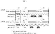
図1は、光ディスク(タイプA,タイプB)の記録レイアウトの一例を示す図である。 FIG. 1 is a diagram showing an example of a recording layout of an optical disc (type A, type B).
タイプA、タイプBのディスクは、ディスク内周側から、BCA(Burst Cutting Area)領域101、PIC(Permanent Information & Control data)領域102、データ記録領域103,104が置されている。BCA領域101は、ディスクの中心側に28.6um間隔に4〜17um幅のバーコードで情報が記載され、データ記録領域の記録密度とは独立した記録密度となっている。これらはディスク製造後にYAGレーザーと呼ばれる強力な赤外線レーザーにより反射膜を焼き切ることにより記録される。本領域はディスク製造後にメーカーの必要情報を記載するための領域であり、例えば各ディスクの識別を行なうためのシリアルID、および暗号化情報などが記録される。
The type A and type B discs are provided with a BCA (Burst Cutting Area)
ここで、BCA領域101におけるデータフォーマットについて詳述する。図20はBCA領域101に記録されるデータ構造の一例である。本例では、BCA領域は4つのデータユニットから構成される。各ユニットは16バイトのデータD(X,Y)と16バイトのパリティP(X,Y)から構成され、これらのデータの8バイト毎に同期用の1バイトのシンクコードSB(V,W)を持つ。このように、BCAはシンクコードを高頻度で持つことでBCAコードの読み出しを容易にしている。また、BCAコードはデータと同じサイズのパリティを持っており、ユーザデータよりもより強力なエラー訂正が可能となる。これにより、信頼性の高いデータ読み出しが可能となる。
これらのことから、BCA領域は、ディスク再生時に読み出しが必須となるディスク密度情報を格納するのに、適した領域であると言える。
Here, the data format in the
From these facts, it can be said that the BCA area is an area suitable for storing disk density information that must be read during disk reproduction.
BCAの各データユニットのデータ先頭には1バイトのコンテンツコードを設け、各ユニットの記載情報内容を表示する。上記記載のようにBCAは容易に高信頼性のデータ読み出しが可能なため、ディスク製造時の固有データ、ディスク管理情報などさまざまの記録が考えられる。そのため、上記コンテンツコードで各ユニット内情報を振り分けることにより、各ユニットで異なるデータの記録を可能とする。 A 1-byte content code is provided at the top of each data unit of the BCA, and the description information content of each unit is displayed. As described above, since BCA can easily read data with high reliability, various records such as unique data and disc management information at the time of disc manufacture can be considered. Therefore, by distributing the information in each unit by the content code, it is possible to record different data in each unit.
2〜16バイトはBCA領域における情報記載領域であり、ディスクのシリアルID、ディスクの基本情報などが記載される。 2 to 16 bytes are an information description area in the BCA area, in which the serial ID of the disk, basic information of the disk, and the like are described.
本実施例では光ディスクのデータ記録密度の違いを判定することを目的とするため、前述のコンテンツコードにより、BCA領域にディスク基本情報が記載されていることが明示された場合の例について説明する。 In order to determine the difference in the data recording density of the optical disk in this embodiment, an example will be described in which it is specified by the above-described content code that the basic disk information is described in the BCA area.
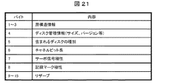
図21はBCA領域にディスク基本情報が記載されている場合における、2〜16バイトのデータフォーマットの一例を示す。本例では、複数層を持つディスクの識別を考慮して、バイト1〜3に層構造情報を配置する。また、規格情報からのディスク識別を可能とするため、バイト4に規格で管理されるディスクの容量、バージョンなどの管理情報を配置する。また、ディスクが異なる種類の複数層から成るディスクであることを考慮して、バイト5にディスクに含まれるROM,Rなどのディスクの種別情報を配置する。また、ディスク再生情報からのディスク識別を可能とするため、バイト6にチャネルクビット長、バイト7にサーボ信号の極性、バイト8に記録マークの極性を配置する。バイト9〜16はリザーブ領域とする。
このように、BCA領域に複数のディスク識別用情報を記載することで、より精度良くディスク識別が可能となる。さらに、前述のようにBCAの記録はディスク製造後に実施されるため、ディスクの製造工程が固定された後においても、上記リザーブ領域に新たなディスク識別用の情報を容易に追加できる。
FIG. 21 shows an example of a data format of 2 to 16 bytes when basic disc information is described in the BCA area. In this example, the layer structure information is arranged in
In this way, by describing a plurality of pieces of disc identification information in the BCA area, disc identification can be performed with higher accuracy. Further, as described above, since the BCA recording is performed after the disc is manufactured, new disc identification information can be easily added to the reserved area even after the disc manufacturing process is fixed.
またPIC領域102は、BDにおける管理情報領域であり、トラックのウォブルに対してウォブル周波数の変化で管理情報を重畳させた領域である。このウォブル周波数はチャネルクロック周波数の整数倍で定義され、高周波グルーブ(HFMグルーブ)を形成している。HFMグルーブの領域ではディスクフォーマットに従ったピット、マークなどによるデータ情報の記録を行わないため、ウォブル周波数をデータ領域の記録密度とは独立して設定可能である。これらはディスク製造時にスタンパ等によりデータ領域のウォブル(溝)と同様に形成され、ディスク製造時にあらかじめ定められた、たとえば記録/再生に必要とされるレーザーパワー値などが記述される。データ記録領域103と104には、それぞれ記録密度25GB/layerと33GB/layerにて情報(データ)を記録する。
The
本実施例では、ディスク製造時に、BCA領域101またはPIC領域102に、さらにデータ記録領域103と104のデータ記録密度などのディスク管理情報を記録する。ここでBCA領域101とPIC領域102は、タイプA、タイプBのいずれのディスクでもユーザデータ記録領域と異なる固有のフォーマットでありタイプA、タイプBで同一である。ディスク管理情報はこのフォーマットに従った特定の記録密度にて記録される。言い換えれば、ディスク管理情報を記述する記録密度は、ディスク内のデータ記録領域103,104のデータ記録密度に依存しないようにする。
In this embodiment, disc management information such as the data recording density of the data recording areas 103 and 104 is further recorded in the
図2は、タイプA,タイプBのディスクにおけるディスク管理情報(データ記録密度情報)の表記例を示す表である。データ記録密度情報もしくはデータ記録密度に関連する情報(例えば一層あたりの記録容量)を記述するときのビット配置の一例である。 FIG. 2 is a table showing an example of notation of disc management information (data recording density information) on type A and type B discs. It is an example of bit arrangement when describing data recording density information or information related to the data recording density (for example, recording capacity per layer).
なお、以降の説明では、データ記録密度情報もしくはデータ記録密度に関連する情報(例えば一層あたりの記録容量)を、単に密度情報と称し、例えば25GB/layerと記載する。 In the following description, data recording density information or information related to the data recording density (for example, recording capacity per layer) is simply referred to as density information, and is described as, for example, 25 GB / layer.
ここでは、記録密度25GB/layer相当(タイプA)を“0000”ビットで、記録密度33GB/layer相当(タイプB)を“0001”ビットと定義して記述している。このビット値を識別することで、当該ディスクの記録密度もしくはデータ記録密度に関連する情報を判別することができる。
Here, the
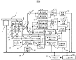
図3は、本実施例における光ディスク記録再生装置の構成例を示す図である。 FIG. 3 is a diagram showing a configuration example of the optical disc recording / reproducing apparatus in the present embodiment.
主な構成要素を説明する。1は光ディスク(ここでは図1に示したBD)、2は光ディスクを回転させるスピンドルモータ、25は光ヘッドである。光ヘッド25は、光ディスク1にレーザー光(波長405nm近傍の青色レーザー)を照射して、ディスク管理情報を読み出すとともに、光ディスク1のデータ記録領域103,104に対し情報の記録/再生を行う。また、複数のデータ記録密度に対応するため、密度判定回路35、第1および第2の再生信号処理回路9,10、第1および第2のウォブル信号処理回路14,15、第1および第2のストラテジ格納メモリ30,31を備える。マイコン32は、ディスク管理情報の読み出し、記録再生処理回路の設定、記録再生動作の実行などを制御する。
The main components will be described.
本実施例では、光ディスクのBCA領域101またはPIC領域102からディスク管理情報を読み出し、密度判定回路35にて対象ディスクの密度情報(25GB/layerか、33GB/layerか)を判別する。その判別結果に従い、第1および第2の再生信号処理回路9,10を切り替えて、復調回路12で再生信号を復調する。また、第1および第2のウォブル信号処理回路14,15を切り替えて、アドレス生成回路17で記録再生アドレスを再生する。また、第1および第2のストラテジ格納メモリ30,31を切り替えて、記録ストラテジ生成回路27にて記録信号を生成する。再生信号処理回路9,10の切り替えでは、最短マーク長やクロック周波数に合わせた再生イコライザの設定、ウォブル信号処理回路14,15の切り替えでは、ウォブル周波数に合わせたアドレス再生の設定、ストラテジ格納メモリ30,31の切り替えでは、クロック周波数に合わせた記録ストラテジの設定を行う。
In this embodiment, disk management information is read from the
図4は、光ディスク記録再生装置の他の構成例を示す図である。前記図3の構成と比較して、スピンドルモータ2の回転を制御する回転制御回路40と、第1および第2の回転制御係数格納メモリ42,43を設け、図3における第1および第2のウォブル信号処理回路14,15を削除した。密度判定回路35により対象ディスクの密度情報(25GB/layerか、33GB/layerか)を判定し、回転制御係数格納メモリ42,43の切り替えを行う。これにより、密度に応じてディスクの回転数を変更し、再生されるウォブル周波数を一定にすることができる。
FIG. 4 is a diagram showing another configuration example of the optical disc recording / reproducing apparatus. Compared with the configuration of FIG. 3, a rotation control circuit 40 for controlling the rotation of the
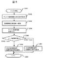
図5は、本実施例の記録再生処理の手順を示すフローチャートである。 FIG. 5 is a flowchart showing the procedure of the recording / reproducing process of this embodiment.
S301では、光ディスク装置にディスクを挿入する。ここでは、ディスクは25GB/layer(タイプA)か、33GB/layer(タイプB)である。 In S301, the disc is inserted into the optical disc apparatus. Here, the disc is 25 GB / layer (type A) or 33 GB / layer (type B).
S302では、ディスクからディスク管理情報(データ記録密度情報)を読み出すための再生条件を設定する。すなわち、BCA領域101またはPIC領域102のフォーマットに従った再生条件を設定する。
In S302, a playback condition for reading disc management information (data recording density information) from the disc is set. That is, the reproduction condition according to the format of the
S303では、光ヘッドをディスク上の管理情報記録領域(BCA領域またはPIC領域)へ移動させる。 In S303, the optical head is moved to the management information recording area (BCA area or PIC area) on the disk.
S304では、管理情報記録領域からディスク管理情報を読み出す。 In S304, the disc management information is read from the management information recording area.
S305では、読み出した記録密度情報から、当該ディスクが25GB/layer(タイプA)か、33GB/layer(タイプB)かを判定する。 In S305, it is determined from the read recording density information whether the disc is 25 GB / layer (type A) or 33 GB / layer (type B).
図20に示すBCA領域からディスク管理情報を読み出してデータ記録密度を判定する場合、以下の方法が考えられる。
1. バイト1に記載されるディスクの層構造の情報からの判別
2. バイト4に記載されるディスクのバージョン情報などの規格管理情報からの判別
3. バイト6に記載されるディスクのチャネルビット情報からの判別
上記の記録密度判定方法により25GB/layer(タイプA)と判定された場合は、S306へ進み、25GB/layer用の記録再生処理条件(再生信号処理回路、ウォブル信号処理回路、記録ストラテジ)に設定する。
In the case where the disk management information is read from the BCA area shown in FIG. 20 to determine the data recording density, the following method can be considered.
1. Discrimination from disc layer structure information described in
2. Discrimination from standard management information such as disk version information described in
3. Discrimination from disc channel bit information described in
33GB/layer(タイプB)と判定された場合は、S307へ進み、33GB/layer用の記録再生処理条件(再生信号処理回路、ウォブル信号処理回路、記録ストラテジ)に設定する。 If it is determined that it is 33 GB / layer (type B), the process proceeds to S307, and the recording / reproduction processing conditions (reproduction signal processing circuit, wobble signal processing circuit, recording strategy) for 33 GB / layer are set.
S308では、ホストから情報の記録または再生指示のコマンドを待ち、指示があったらS306またはS307にて設定した条件にて記録/再生動作を実行する。 In step S308, the host waits for an information recording or reproduction instruction command from the host. If there is an instruction, the recording / reproducing operation is executed under the conditions set in step S306 or S307.
本実施例では、ディスク管理情報はBCA領域またはPIC領域に特定のフォーマットにて記録されているので、管理情報の再生条件は一義に決定される。よって、いずれの記録密度のディスクが挿入されても、管理情報の再生条件は同一であるため、当該ディスクの記録密度を誤りなく容易に判定し、それに合った記録再生動作を実行することができる。 In this embodiment, since the disc management information is recorded in the BCA area or PIC area in a specific format, the reproduction condition of the management information is uniquely determined. Therefore, regardless of the recording density of the disc inserted, the playback conditions of the management information are the same. Therefore, the recording density of the disc can be easily determined without error, and the recording / playback operation corresponding to it can be executed. .
本実施例は、データ記録密度として標準密度(25GB/layer)の領域と高密度(33GB/layer)の領域とが、同一面内(同一層内)で混在するディスク(以下、タイプCと呼ぶ)を対象とする。簡単のために層数は単層とするが、多層であっても構わない。タイプCのディスクは、標準密度(25GB/layer)対応の従来装置と高密度(33GB/layer)対応の高密度対応装置のいずれの装置でも、装置が対応する領域に対して記録、再生が可能である。 In this embodiment, a disk having a standard density (25 GB / layer) area and a high density (33 GB / layer) area in the same plane (in the same layer) as data recording density (hereinafter referred to as type C). ). For simplicity, the number of layers is a single layer, but multiple layers may be used. Type C discs can be recorded and played back on the device's compatible area on both standard density (25 GB / layer) compatible devices and high density (33 GB / layer) compatible devices. It is.
図6は、光ディスク(タイプC)の記録フォーマットの一例を示す図である。(a)は平面構成、(b)は半径方向の構成を示す。 FIG. 6 is a diagram showing an example of the recording format of the optical disc (type C). (A) shows a plane configuration, and (b) shows a configuration in the radial direction.
タイプCのディスクは、同一面内に内周側から、BCA領域111、PIC領域112、第1の記録密度領域(25GB/layer)113、第2の記録密度領域(33GB/layer)114の順に配置されている。符号115は、第1の記録密度領域113と第2の記録密度領域114との境界である。この境界部115には、半径方向に所定幅の未記録部(ギャップ領域)を持たせても良い。BCA領域111またはPIC領域112には、ディスク管理情報(データ記録密度情報)を記録する。BCA領域111とPIC領域112はユーザデータ記録領域と異なる固有のフォーマットを有するので、ディスク管理情報は特定の記録密度にて記録される。言い換えれば、ディスク管理情報の記録密度は、ディスク内のデータ記録領域113,114のデータ記録密度に依存しない。
A type C disc has a
図7は、ディスクCにおけるディスク管理情報(データ記録密度情報)の表記例を示す図である。密度情報を記述するときのビット配置の一例である。情報の内容としては、複数の記録密度が混在するかどうかを示す項目(Hyblid)を追加し、また記録密度境界の位置情報(アドレス値)を記述する。Hyblid=“1”であれば混在ディスク(タイプC)であることを示し、複数の密度情報と境界アドレス値を記述する。Hyblid=“0”であれば、単一の記録密度(タイプA,タイプB)であることを示す。図7の表記によれば、タイプA,B,Cを判別することができる。 FIG. 7 is a diagram showing a notation example of disk management information (data recording density information) in the disk C. It is an example of bit arrangement when describing density information. As information contents, an item (Hybrid) indicating whether or not a plurality of recording densities are mixed is added, and position information (address value) of the recording density boundary is described. If Hybrid = “1”, this indicates a mixed disk (type C), and a plurality of density information and boundary address values are described. If Hybrid = "0", it indicates a single recording density (type A, type B). According to the notation of FIG. 7, types A, B, and C can be distinguished.
なお、ディスクCにおけるデータ記録密度情報などのディスク管理情報の記載方法としては、図20、21に示すBCAコードによる記載も考えられる。 As a method for describing the disc management information such as the data recording density information on the disc C, the description using the BCA code shown in FIGS.
図20に示すBCA領域からディスク管理情報を読み出してデータ記録密度を判定する場合、以下の方法が考えられる。
1. バイト1に記載されるディスクの層構造の情報からの判別
2. バイト4に記載されるディスクのバージョン情報などの規格管理情報からの別
3. バイト6に記載されるディスクのチャネルビット情報からの判別
図8は、本実施例における光ディスク記録再生装置の構成例を示す図である。本実施例では、前記図3の構成において、密度情報格納メモリ50、アドレス判定回路51、トラッキングよぎり数(TES)カウント回路52を備えたものである。
In the case where the disk management information is read from the BCA area shown in FIG.
1. Discrimination from disc layer structure information described in
2. Separate from standard management information such as disk version information described in
3. Discrimination from Channel Bit Information of Disc Described in
タイプCのディスクから読み出された密度情報や境界アドレス情報は密度情報格納メモリ50に格納され、これらはアドレス判定回路51にて参照される。アドレス判定回路51はアドレス生成回路17からの現在アドレス情報を受け、対象領域の密度(25GB/layerか、33GB/layerか)を判定する。判定結果により、第1および第2の再生信号処理回路9,10の切り替えと、第1および第2のウォブル信号処理回路14,15の切り替えと、第1および第2のストラテジ格納メモリ30,31の切り替えを行う。また、目標領域(目標アドレス)までのトラックよぎり数を計算し、TESカウント回路52によりトラック数をカウントすることで目標領域へのシーク動作を行う。
The density information and boundary address information read from the type C disk are stored in the density information storage memory 50, and these are referred to by the address determination circuit 51. The address determination circuit 51 receives the current address information from the
図9は、トラッキングよぎり数によるアドレス判定方法を示す図である。横軸はアドレス値(半径位置)、縦軸はTESカウント回路52によるトラックよぎり(TES)数累計である。区間201は25GB/layerの領域、区間202は33GB/layerの領域で、境界アドレスは“1000000h”ある。アドレス増加とともにTES数累計は増加するが、その勾配は記録密度に依存し区間201と区間202とで異なる。境界アドレスが“1000000h”のときのTES数累計CNT1を算出しておき、TESカウント回路52によりCNT1までカウントすることで、境界アドレスにシークすることができる。さらに、境界部からのトラッキングよぎり数をカウントすることで、目標領域(アドレス)に到達することができる。
FIG. 9 is a diagram illustrating an address determination method based on the number of tracking crossings. The horizontal axis represents the address value (radius position), and the vertical axis represents the cumulative number of track crossings (TES) by the
図10は、本実施例の記録再生処理の手順を示すフローチャートである。(a)はディスクローディング時の工程、(b)は記録再生処理時の工程である。 FIG. 10 is a flowchart showing the procedure of the recording / reproducing process of this embodiment. (A) is a step at the time of disk loading, and (b) is a step at the time of recording / reproducing processing.
S401では、光ディスク装置にディスクを挿入する。ここでは、ディスクは標準密度(25GB/layer)の領域と高密度(33GB/layer)の領域とが、同一面内で混在するディスク(タイプC)である。 In S401, the disc is inserted into the optical disc apparatus. Here, the disk is a disk (type C) in which a standard density (25 GB / layer) area and a high density (33 GB / layer) area are mixed in the same plane.
S402では、ディスクからディスク管理情報(データ記録密度情報)を読み出すための再生条件を設定する。すなわち、BCA領域111またはPIC領域112のフォーマットに適合する再生条件を設定する。
In S402, a playback condition for reading the disc management information (data recording density information) from the disc is set. That is, the reproduction condition that matches the format of the
S403では、光ヘッドをディスク上の管理情報記録領域(BCA領域111またはPIC領域112)へ移動させる。
In S403, the optical head is moved to the management information recording area (
S404では、管理情報記録領域からディスク管理情報を読み出す。 In S404, the disc management information is read from the management information recording area.
S405では、管理情報記録領域から読み出したディスク管理情報(データ記録密度、密度境界アドレス値)を密度情報格納メモリ50に格納する。 In S405, the disc management information (data recording density, density boundary address value) read from the management information recording area is stored in the density information storage memory 50.
S406では、ホストから情報の記録または再生指示のコマンドを待つ。 In step S406, the host waits for an information recording or reproduction instruction command from the host.
次に記録再生処理に進む。 Next, the process proceeds to the recording / reproducing process.
S411では、ホストから情報の記録または再生のコマンドを受ける。 In S411, a command for recording or reproducing information is received from the host.
S412では、受けたコマンドから記録/再生の目標アドレスを取得する。 In S412, the target address for recording / reproduction is acquired from the received command.
S413では、目標アドレスと、密度情報格納メモリ50に格納しているディスク管理情報(データ記録密度、密度境界アドレス値)とから、目標アドレスでの記録/再生条件に設定する。すなわち、記録再生処理条件(再生信号処理回路、ウォブル信号処理回路、記録ストラテジ)を25GB/layer用の条件、または33GB/layer用の条件に設定する。 In S413, the recording / reproduction conditions at the target address are set from the target address and the disc management information (data recording density, density boundary address value) stored in the density information storage memory 50. That is, the recording / reproduction processing conditions (reproduction signal processing circuit, wobble signal processing circuit, recording strategy) are set to the conditions for 25 GB / layer or the conditions for 33 GB / layer.
S414では、目標アドレスと密度情報格納メモリ50に格納しているディスク管理情報とから、目標アドレスまでの各領域のデータ記録密度と、目標アドレスまでのトラックよぎり数(TES)を算出する。 In S414, the data recording density of each area up to the target address and the number of track crossings (TES) up to the target address are calculated from the target address and the disk management information stored in the density information storage memory 50.
S415では、トラックよぎり数をカウントして、目標領域へシーク動作する。 In S415, the number of track crossings is counted and a seek operation is performed to the target area.
S416では、到着位置のアドレスを読み出して、シーク終了を確認する。 In S416, the address of the arrival position is read and the end of seek is confirmed.
S417では、データの記録/再生動作を開始する。 In S417, the data recording / reproducing operation is started.
S418では、記録/再生アドレスが記録密度の境界アドレスかどうかを判定する。境界の場合はS419へ、境界でなければS422へ進む。 In S418, it is determined whether the recording / reproducing address is a boundary address of recording density. If it is a boundary, the process proceeds to S419. If not, the process proceeds to S422.
S419では、記録/再生動作を中断する。 In S419, the recording / reproducing operation is interrupted.
S420では、密度情報格納メモリ50から次の領域の記録密度情報を読み出し、その密度に対応する記録再生処理条件(再生信号処理回路、ウォブル信号処理回路、記録ストラテジ)に設定する。 In S420, the recording density information of the next area is read from the density information storage memory 50, and the recording / reproduction processing conditions (reproduction signal processing circuit, wobble signal processing circuit, recording strategy) corresponding to the density are set.
S421では、次の記録密度領域まで移動する。 In S421, it moves to the next recording density area.
S422では、1アドレス単位で記録/再生処理を行う。 In S422, recording / reproduction processing is performed in units of one address.
S423では、記録/再生用データが全て終了したかどうか判定する。残りのデータがあればS418へ戻り処理を継続する。残りのデータがなくなれば、S424にて記録再生処理を終了する。 In S423, it is determined whether or not all the recording / playback data has been completed. If there is remaining data, the process returns to S418 and continues. If there is no remaining data, the recording / reproducing process ends in S424.
本実施例によれば、データ記録密度が同一面内で混在するディスク(タイプC)においても、BCA領域またはPIC領域にディスク管理情報(記録密度の配置、境界アドレス)が固定のフォーマットにて記録されている。よって、管理情報の再生条件は一義に決定され、誤りなく容易に判定できる。そして、ディスク内の目標位置の記録密度に従い、それぞれの記録密度に合った記録再生動作を実行することができる。 According to this embodiment, even in a disc (type C) in which data recording densities are mixed in the same plane, disc management information (recording density arrangement, boundary address) is recorded in a fixed format in the BCA area or PIC area. Has been. Therefore, the reproduction condition of the management information is uniquely determined and can be easily determined without error. Then, according to the recording density at the target position in the disc, a recording / reproducing operation suitable for each recording density can be executed.
本実施例は、データ記録密度が標準密度(25GB/layer)の層と高密度(33GB/layer)の層とが混在する多層ディスク(以下、タイプDと呼ぶ)を対象とする。タイプDのディスクは、標準密度(25GB/layer)対応の従来装置と高密度(33GB/layer)対応の高密度対応装置のいずれの装置でも装置が対応する層に対して記録、再生が可能である。 The present embodiment targets a multi-layer disc (hereinafter referred to as type D) in which a data recording density is a mixture of a standard density (25 GB / layer) layer and a high density (33 GB / layer) layer. Type D discs can be recorded and played back on the layers supported by both the conventional device that supports standard density (25 GB / layer) and the high-density device that supports high density (33 GB / layer). is there.
図11は、光ディスク(タイプD)の記録フォーマットの一例を示す図である。ここでは、25GB/layerの層と33GB/layerの層とが交互に4層配置した構成の例である。ディスク表面側から各記録層をL0,L1,L2,L3とする。各層において、内周側から、BCA領域121、PIC領域122、データ記録領域123,124を配置している。各層のデータ記録領域123,124では25GB/layerまたは33GB/layerのデータ記録密度でデータが記録される。なお、BCA領域121は各層にて存在するが、PIC領域122はL0層のみに形成する。本例では、ディスク管理情報(データ記録密度情報)をPIC領域122に記録する。PIC領域122は、ユーザデータ記録領域と異なる固有のフォーマットを有するので、ディスク管理情報は特定の記録密度にて記録される。言い換えれば、ディスク管理情報の記録密度は、近接するデータ記録領域123のデータ記録密度に依存しない。なお、PIC領域122のあるL0層の記録密度を常に標準の25GB/layerとすることで、標準密度(25GB/layer)対応の従来装置との互換性を保持することができるという効果がある。あるいは、PIC領域122をデータ記録密度が最低となる記録層に配置するようにしても良い。
FIG. 11 is a diagram showing an example of a recording format of the optical disc (type D). In this example, 25 GB / layer layers and 33 GB / layer layers are alternately arranged in four layers. The recording layers are designated as L0, L1, L2, and L3 from the disk surface side. In each layer, a
図12は、ディスクDにおけるディスク管理情報(データ記録密度情報)の表記例を示す図である。密度情報を記述するときのビット配置の一例である。情報の内容としては、各層毎の記録密度の記述欄を設け、データ記録密度を2ビットで記述する。ここでは8層分の欄を設け、記録密度25GB/layerを“00”ビットで、記録密度33GB/layerを“01”ビットと定義して記述している。
FIG. 12 is a diagram showing a notation example of disk management information (data recording density information) in the disk D. It is an example of bit arrangement when describing density information. As information contents, a description column of recording density for each layer is provided, and the data recording density is described by 2 bits. Here, a column for 8 layers is provided, and the
図13は、本実施例における光ディスク記録再生装置の構成例を示す図である。本実施例では、前記図3の構成において、密度情報格納メモリ60、フォーカスエラー信号(FES)生成回路62、フォーカスエラーサーボ回路63、現在層判定回路64を備えたものである。FES生成回路62は各層からのよぎり信号を生成し、フォーカスエラーサーボ回路63は目標層へのフォーカス引き込みを行う。
FIG. 13 is a diagram illustrating a configuration example of an optical disc recording / reproducing apparatus according to the present embodiment. In this embodiment, the configuration of FIG. 3 includes a density information storage memory 60, a focus error signal (FES)
タイプDのディスクから読み出された各層の密度情報は、密度情報格納メモリ60に格納され、現在層判定回路64にて参照される。現在層判定回路64は、FES生成回路62からのFE信号と、アドレス生成回路17からの再生アドレスを入力して、現在層が何層目かを判定する。また密度情報格納メモリ60からの密度情報により、現在層の記録密度(25GB/layerか、33GB/layerか)を判定する。判定結果により第1および第2の再生信号処理回路9,10の切り替えと、第1および第2のウォブル信号処理回路14,15の切り替えと、第1および第2のストラテジ格納メモリ30,31の切り替えを行う。
The density information of each layer read from the type D disk is stored in the density information storage memory 60 and is referred to by the current
図14は、本実施例の記録再生処理の手順を示すフローチャートである。(a)はディスクローディング時の工程、(b)は記録再生処理時の工程である。 FIG. 14 is a flowchart showing the procedure of the recording / reproducing process of this embodiment. (A) is a step at the time of disk loading, and (b) is a step at the time of recording / reproducing processing.
S501では、光ディスク装置にディスクを挿入する。ここでは、ディスクは標準密度(25GB/layer)の層と高密度(33GB/layer)の層とが多層化されて混在するディスク(タイプD)である。 In S501, the disc is inserted into the optical disc apparatus. Here, the disc is a disc (type D) in which a standard density (25 GB / layer) layer and a high density (33 GB / layer) layer are mixed and mixed.
S502では、光ヘッドのフォーカスを、ディスク管理情報(データ記録密度情報)が記録されている特定の層(L0層)へ引き込む。 In S502, the focus of the optical head is drawn into a specific layer (L0 layer) in which disk management information (data recording density information) is recorded.
S503では、ディスクからディスク管理情報を読み出すための再生条件を設定する。 In S503, a playback condition for reading the disc management information from the disc is set.
S504では、光ヘッドをディスク上の管理情報記録領域(PIC領域122)へ移動させる。 In S504, the optical head is moved to the management information recording area (PIC area 122) on the disk.
S505では、管理情報記録領域からディスク管理情報を読み出す。 In S505, the disc management information is read from the management information recording area.
S506では、管理情報記録領域から読み出したディスク管理情報(各層のデータ記録密度)を密度情報格納メモリ60に格納する。 In S506, the disc management information (data recording density of each layer) read from the management information recording area is stored in the density information storage memory 60.
S507では、ホストから情報の記録または再生指示のコマンドを待つ。 In step S507, the host waits for an information recording or reproduction instruction command from the host.
次に記録再生処理に進む。 Next, the process proceeds to the recording / reproducing process.
S511では、ホストから情報の記録または再生のコマンドを受ける。 In step S511, a command for recording or reproducing information is received from the host.
S512では、受けたコマンドから記録/再生の目標アドレスを取得する。 In S512, the recording / playback target address is acquired from the received command.
S513では、記録/再生の目標アドレスから目標層が何層目かを計算する。 In S513, the target layer number is calculated from the target address for recording / reproduction.
S514では、密度情報格納メモリ60に格納した情報を参照し、目標層の記録密度を判定する。 In S514, the information stored in the density information storage memory 60 is referred to determine the recording density of the target layer.
記録密度が25GB/layerの場合は、S515へ進み、25GB/layer用の記録再生処理条件(再生信号処理回路、ウォブル信号処理回路、記録ストラテジ)に設定する。 When the recording density is 25 GB / layer, the process proceeds to S515, and the recording / reproduction processing conditions (reproduction signal processing circuit, wobble signal processing circuit, recording strategy) for 25 GB / layer are set.
記録密度が33GB/layerの場合は、S516へ進み、33GB/layer用の記録再生処理条件(再生信号処理回路、ウォブル信号処理回路、記録ストラテジ)に設定する。 If the recording density is 33 GB / layer, the process proceeds to S516, and the recording / reproduction processing conditions (reproduction signal processing circuit, wobble signal processing circuit, recording strategy) for 33 GB / layer are set.
S517では、光ヘッドのフォーカスを目標層へ引き込む。 In S517, the focus of the optical head is pulled into the target layer.
S518では、到着位置のアドレスを読み出して、シーク終了を確認する。 In S518, the address of the arrival position is read and the end of seek is confirmed.
S519では、記録/再生動作を開始する。 In S519, the recording / reproducing operation is started.
本実施例によれば、各層においてデータ記録密度が異なる多層ディスク(タイプD)においても、PIC領域にディスク管理情報(各層の記録密度)が固有のフォーマットにて記録されている。よって、管理情報の再生条件は一義に決定され、誤りなく容易に判定できる。そして、ディスク内の目標層の記録密度に従い、それぞれの記録密度に合った記録再生動作を実行することができる。 According to this embodiment, even in a multi-layer disc (type D) having different data recording densities in each layer, the disc management information (recording density of each layer) is recorded in a unique format in the PIC area. Therefore, the reproduction condition of the management information is uniquely determined and can be easily determined without error. Then, according to the recording density of the target layer in the disc, a recording / reproducing operation suitable for each recording density can be executed.
本実施例でも、前記実施例3と同様に、多層ディスクでデータ記録密度が標準密度(25GB/layer)の層と高密度(33GB/layer)の層とが混在するディスクを対象とする。ただし、ディスク管理情報(データ記録密度情報)を、標準密度(25GB/layer)のデータ記録領域の一部領域に記録する構成である(以下、このディスクをタイプEと呼ぶ)。この場合、データ記録領域を利用して管理情報を記録するので、ディスク製造後に情報を記録することが可能である。例えば、ディスク製造者は、ディスク製造後に製造した各ディスクを検査し、使用不可の層が存在しないかどうかを判定する。そしてその判定結果を、各層の記録密度情報とともにディスク管理情報に含めて記録することができる。 In the present embodiment, as in the third embodiment, a multi-layer disk having a data recording density of a standard density (25 GB / layer) layer and a high density (33 GB / layer) layer is targeted. However, the disc management information (data recording density information) is recorded in a partial area of the standard density (25 GB / layer) data recording area (hereinafter this disc is referred to as type E). In this case, since the management information is recorded using the data recording area, the information can be recorded after the disc is manufactured. For example, the disc manufacturer inspects each disc manufactured after disc manufacture and determines whether there are any unusable layers. Then, the determination result can be recorded in the disc management information together with the recording density information of each layer.
図15は、光ディスク(タイプE)の記録フォーマットの一例を示す図である。 FIG. 15 is a diagram showing an example of a recording format of the optical disc (type E).
ディスクは、25GB/layerの層と33GB/layerの層とを交互に4層配置し、ディスク表面側から各層をL0,L1,L2,L3とする。また内周側から、BCA領域131、PIC領域132(L0層のみ)、データ記録領域133,134を配置している。そして、記録密度が標準密度(25GB/layer)であるL0層とL2層のデータ記録領域133の一部には、管理情報記録領域135を設ける。このように管理情報を標準の記録密度の領域に記録することで、管理情報のフォーマットが一義に決定され、また従来の装置でも確実に管理情報を読み出すことができる。なお、L0層は常に標準密度(25GB/layer)の記録層であるように決めておけば、管理情報をより確実に読み出すことができる。あるいは、管理情報記録領域135をデータ記録密度が最低となる記録層のデータ記録領域に設けても良い。
The disk has four layers of 25 GB / layer and 33 GB / layer alternately arranged, and each layer is L0, L1, L2, L3 from the disk surface side. In addition, a
管理情報記録領域135には、エンボスピットや書換え可能なマークで管理情報を記録する。管理情報の内容は、各層のデータ記録密度とともにその層の使用可否情報を含む。例えば使用可能であれば“1”ビット、使用不可であれば“0”ビットとする。
In the management
図16は、光ディスク(タイプE)の記録フォーマットの他の例を示す図である。図15と区別するためにタイプE’とする。 FIG. 16 is a diagram showing another example of the recording format of the optical disc (type E). In order to distinguish from FIG.
これは、標準記録密度(25GB/layer)の層がどの層であるか、装置が分からない場合でも対応可能なようにするため、全ての層に管理情報記録領域136を設けたものである。いずれの領域も、標準記録密度(25GB/layer)のフォーマットに従い、エンボスピットや書換え可能なマークで管理情報を記録する。
This is because the management
光ディスク装置は、ディスクローディングのときディスク管理情報(記録密度情報、使用可否情報)を読み出し、密度情報格納メモリに格納する。記録再生時には各層の記録密度に応じて記録再生条件を切り替えるとともに、使用不可の層については記録再生動作を中止することで、無駄な動作を回避することができる。 The optical disc apparatus reads disc management information (recording density information, availability information) at the time of disc loading and stores it in a density information storage memory. At the time of recording / reproducing, the recording / reproducing condition is switched according to the recording density of each layer, and the useless operation can be avoided by stopping the recording / reproducing operation for the unusable layer.
図17は、本実施例の記録再生処理の手順を示すフローチャートである。ここでは、ディスクローディング時の工程を示す。 FIG. 17 is a flowchart showing the procedure of the recording / reproducing process of this embodiment. Here, the process at the time of disk loading is shown.
S601では、光ディスク装置にディスクを挿入する。ここでは、ディスクは標準密度(25GB/layer)の層と高密度(33GB/layer)の層とが多層化されて混在するディスク(タイプE、タイプE’)である。管理情報は、標準密度(25GB/layer)のデータ記録領域に記録されている。 In S601, the disc is inserted into the optical disc apparatus. Here, the disk is a disk (type E, type E ′) in which a layer having a standard density (25 GB / layer) and a layer having a high density (33 GB / layer) are mixed. The management information is recorded in a data recording area of standard density (25 GB / layer).
S602では、光ヘッドのフォーカスを、標準密度(25GB/layer)の層へ引き込む。図15のディスク(タイプE)の場合には、L0層またはL2層へ引き込む。図16のディスク(タイプE’)の場合には、いずれの層でも良い。 In S602, the focus of the optical head is drawn into a layer having a standard density (25 GB / layer). In the case of the disc of FIG. 15 (type E), it is drawn into the L0 layer or the L2 layer. In the case of the disc of FIG. 16 (type E ′), any layer may be used.
S603では、ディスクからディスク管理情報を読み出すための再生条件を設定する。すなわち、標準密度(25GB/layer)の再生条件に設定する。 In S603, a playback condition for reading the disc management information from the disc is set. That is, the reproduction condition is set to the standard density (25 GB / layer).
S604では、光ヘッドを管理情報記録領域135,136へ移動させる。
In step S604, the optical head is moved to the management
S605では、管理情報記録領域からディスク管理情報を読み出す。 In S605, the disc management information is read from the management information recording area.
S606では、読み出したディスク管理情報(記録密度情報、使用可否情報)を密度情報格納メモリ60に格納する。 In S606, the read disk management information (recording density information, availability information) is stored in the density information storage memory 60.
S607では、ホストから情報の記録または再生指示のコマンドを待ち、コマンドを受けたら記録再生処理に進む。 In step S607, the host waits for an information recording or reproduction instruction command from the host.
記録再生工程では、目標層の記録密度を判定して、記録密度に応じて記録再生条件を切り替える。もしも目標層が使用不可の層である場合は、その層での記録再生動作を中止し、必要に応じてホストに報告する。 In the recording / reproducing process, the recording density of the target layer is determined, and the recording / reproducing conditions are switched according to the recording density. If the target layer is an unusable layer, the recording / reproducing operation in that layer is stopped and reported to the host as necessary.
本実施例によれば、各層においてデータ記録密度が異なる多層ディスク(タイプE、タイプE’)において、標準密度のデータ記録領域の一部領域にディスク管理情報(各層の記録密度、使用可否情報)が標準密度のフォーマットにて記録されている。よって、管理情報の再生条件は一義に決定され、誤りなく判定できる。また、ディスク内の目標層の記録密度に従い、それぞれの記録密度に合った記録再生動作を実行するだけでなく、各記録層の使用可否情報を参照することで、使用不可の記録層を回避することができる。 According to this embodiment, in a multi-layer disc (type E, type E ′) having different data recording densities in each layer, disc management information (recording density of each layer, availability information) in a part of the standard density data recording region. Are recorded in a standard density format. Therefore, the reproduction condition of the management information is uniquely determined and can be determined without error. Further, according to the recording density of the target layer in the disc, not only the recording / reproducing operation suitable for each recording density is performed, but also the unusable recording layer is avoided by referring to the availability information of each recording layer. be able to.
以上説明した各実施例では、データ記録密度が25GB/layerと33GB/layerの2種類について説明したが、記録密度はこれに限定するものではない。また、データ記録密度が3種類以上存在しても同様に適用できる。 In each of the embodiments described above, two types of data recording densities of 25 GB / layer and 33 GB / layer have been described. However, the recording density is not limited to this. The present invention can be similarly applied even when there are three or more data recording densities.
本実施例では前記第1の実施例と同様に多層ブルーレイディスク(BD)において、データ記録密度が全層とも標準密度(25GB/layer)のディスク(以下、タイプAと呼ぶ)、または全層とも高密度(33GB/layer)のディスク(以下、タイプBと呼ぶ)を対象とする。層数については、例えば25GB/layer×4層構成、33GB/layer×3層構成として、両者ともディスク全体の容量を100GBとしたものである。上記タイプA,タイプBのディスクにおけるディスク管理情報(データ記録密度情報)の表記方法については、図1に示す第1の実施例と同様であり、ここでは説明を省略する。 In the present embodiment, as in the first embodiment, in a multi-layer Blu-ray disc (BD), the data recording density of all layers is a standard density (25 GB / layer) disc (hereinafter referred to as type A), or all layers. A high density (33 GB / layer) disk (hereinafter referred to as type B) is targeted. Regarding the number of layers, for example, a 25 GB / layer × 4 layer configuration and a 33 GB / layer × 3 layer configuration are used, and both have a capacity of 100 GB as a whole. The notation method of the disc management information (data recording density information) in the type A and type B discs is the same as that in the first embodiment shown in FIG. 1, and the description is omitted here.
本実施例では、上記タイプAのディスクとタイプBのディスクに対して、第1の実施例で説明したデータ記録密度と独立した記録密度の領域、例えばBCA、PIC領域に記載されたディスク管理情報からのデータ記録密度情報を判別し、所定のデータ記録密度と異なるディスクについては、再生処理、および記録処理を停止する例について説明する。この例は、当該装置に対して、装置が再生動作もしくは記録動作に対応していないフォーマットのディスクを正しく認識させ、その結果を用いて、当該ディスクを排出する、イジェクト動作以外の動作を受付けなくする等の処理を行うことにより、ディスクまたは装置に悪影響が発生するのを防止することを目的とする。
本実施例における記録再生装置の構成例を図19に示す。本記録再生装置は標準記録密度の光ディスクだけに対応し、高記録密度の光ディスクには対応しないものを想定している。
In this embodiment, for the type A disk and the type B disk, disk management information described in areas of recording density independent of the data recording density described in the first embodiment, for example, BCA and PIC areas. An example of discriminating data recording density information from the disc and stopping the reproduction processing and recording processing for a disc having a data recording density different from the predetermined data recording density will be described. In this example, the device correctly recognizes a disc of a format that does not support the playback operation or recording operation, and uses the result to eject the disc and accept no operation other than the eject operation. It is an object to prevent the disk or the apparatus from being adversely affected by performing the process such as
A configuration example of the recording / reproducing apparatus in the present embodiment is shown in FIG. This recording / reproducing apparatus is assumed to be compatible only with a standard recording density optical disk and not a high recording density optical disk.
図18は本実施例の処理の手順を示すフローチャートである。ここでは、ディスクローディング時の工程を示す。
S701では、光ディスク装置にディスクを挿入する。ここでは、ディスクは25GB/layer(タイプA)か、33GB/layer(タイプB)である。
FIG. 18 is a flowchart showing the processing procedure of this embodiment. Here, the process at the time of disk loading is shown.
In S701, the disc is inserted into the optical disc apparatus. Here, the disc is 25 GB / layer (type A) or 33 GB / layer (type B).
S702では、ディスクからディスク管理情報(データ記録密度情報)を読み出すための再生条件を設定する。すなわち、図2に示すBCA領域101またはPIC領域102のフォーマットに従った再生条件を設定する。
S703では、光ヘッドをディスク上の管理情報記録領域(BCA領域またはPIC領域)へ移動させる。
In S702, a reproduction condition for reading the disc management information (data recording density information) from the disc is set. That is, the reproduction condition according to the format of the
In S703, the optical head is moved to the management information recording area (BCA area or PIC area) on the disk.
S704では、管理情報記録領域からディスク管理情報を読み出す。 In S704, the disc management information is read from the management information recording area.
図20に示すBCA領域からディスク管理情報を読み出してデータ記録密度を判定する場合、以下の方法が考えられる。
1. バイト1に記載されるディスクの層構造の情報からの判別
2. バイト4に記載されるディスクのバージョン情報などの規格管理情報からの判別
3. バイト6に記載されるディスクのチャネルビット情報からの判別
S705では、読み出した記録密度情報から、当該ディスクのデータ記録密度が所定の記録密度、例えば25GB/layer(タイプA)であるかどうかを判定する。
In the case where the disk management information is read from the BCA area shown in FIG.
1. Discrimination from disc layer structure information described in
2. Discrimination from standard management information such as disk version information described in
3. Discrimination from disc channel bit information described in
当該ディスクの記録密度が25GB/layer(タイプA)である場合はS706に進み、第1の実施例と同様に25GB/layer用の記録再生処理条件(再生信号処理回路、ウォブル信号処理回路、記録ストラテジ)を設定し、S707のホストから情報の記録または再生指示のコマンドを待ち状態(レディ)とする。 If the recording density of the disc is 25 GB / layer (type A), the process proceeds to S706, and the recording / playback processing conditions for 25 GB / layer (playback signal processing circuit, wobble signal processing circuit, recording) as in the first embodiment. Strategy) is set, and a command for recording or reproducing information from the host in S707 is set in a waiting state (ready).
当該ディスクの記録密度が25GB/layer(タイプA)以外である場合は処理S707に進み、光ディスク装置からのディスクの排出処理を行う。 If the recording density of the disc is other than 25 GB / layer (type A), the process proceeds to step S707, and the disc is ejected from the optical disc apparatus.
本実施例のようなディスク判定処理が無い場合、例えば上記タイプAのみの記録、再生に対応した光ディスク装置に、タイプBのディスクが挿入された場合には データ記録密度の違いから再生処理、記録処理不能となり、最悪のケースとして例えばタイプBディスク上の記録データを破壊するなどの事故の発生などが考えられる。これに対して、本実施例のようにデータ記録密度と独立した記録密度の領域からディスク記録情報を判定して適切にディスク排出処理を行うことにより、上記の事故発生を未然に防ぐことができる。 When there is no disc determination processing as in the present embodiment, for example, when a type B disc is inserted into an optical disc apparatus that supports recording and reproduction of the above type A, the reproduction processing and recording are performed due to the difference in data recording density. Processing is impossible, and as a worst case, for example, an accident such as destruction of recorded data on a type B disc can be considered. On the other hand, the occurrence of the above-mentioned accident can be prevented beforehand by determining the disc recording information from the recording density area independent of the data recording density and appropriately performing the disc ejection processing as in this embodiment. .
なお、本発明の第1の実施例1、および第5の実施例5では、ディスク層数の一例として、25GB/layer×4層構成、33GB/layer×3層構成による容量100GBのディスクを示したが、本発明は例えばタイプAのディスクを1層、もしくは2層構成、タイプBのディスクを3層、もしくは4層とした場合などでも同様の効果を得られることは言うまでもない。 In the first and fifth embodiments of the present invention, as an example of the number of disk layers, a disk having a capacity of 100 GB with a 25 GB / layer × 4 layer configuration and a 33 GB / layer × 3 layer configuration is shown. However, it goes without saying that the present invention can provide the same effect even when, for example, the type A disc has one or two layers and the type B disc has three or four layers.
また、本発明ではユーザデータの異なる記録密度の例として、1層あたり25GBと33GBの例を示したが、2種類以上の異なるユーザデータ記録密度の領域があれば、上記記録密度の値にとらわれるものではない。 Further, in the present invention, as an example of different recording densities of user data, an example of 25 GB and 33 GB per layer is shown. However, if there are two or more types of different user data recording densities, the above recording density values are used. It is not a thing.
1…光ディスク、
2…スピンドルモータ、
9,10…再生信号処理回路、
12…復調回路、
14,15…ウォブル信号処理回路、
17…アドレス生成回路、
25…光ヘッド、
27…記録ストラテジ生成回路、
30,31…ストラテジ格納メモリ、
32…マイコン、
35…密度判定回路、
40…回転制御回路、
42,43…回転制御係数格納メモリ、
50,60…密度情報格納メモリ、
51…アドレス判定回路、
52…トラッキングよぎり数(TES)カウント回路、
62…フォーカスエラー信号(FES)生成回路、
64…現在層判定回路、
101,111,121,131…BCA(Burst Cutting Area)領域、
102,112,122,132…PIC(Permanent Information & Control data)領域、
103,104,113,114,123,124,133,134…データ記録領域、
135,136…管理情報記録領域。
1 ... Optical disc,
2 ... Spindle motor,
9, 10 ... reproduction signal processing circuit,
12: Demodulation circuit,
14, 15 ... wobble signal processing circuit,
17 ... Address generation circuit,
25 ... Optical head,
27. Recording strategy generation circuit,
30, 31 ... strategy storage memory,
32 ... Microcomputer,
35 ... Density judgment circuit,
40: Rotation control circuit,
42, 43 ... rotation control coefficient storage memory,
50, 60 ... density information storage memory,
51. Address determination circuit,
52 ... Tracking crossing number (TES) count circuit,
62 ... a focus error signal (FES) generation circuit,
64 ... current layer judgment circuit,
101, 111, 121, 131 ... BCA (Burst Cutting Area) area,
102, 112, 122, 132 ... PIC (Permanent Information & Control data) area,
103, 104, 113, 114, 123, 124, 133, 134 ... data recording area,
135, 136... Management information recording area.
Claims (4)
上記第1と第2の光ディスクのBCA(Burst Cutting Area)領域に上記データ記録領域のデータ記録密度の情報を含むディスク管理情報が記録されているものであって、
上記第1の光ディスクの1層あたりのデータ記録密度は25GBであり、
上記第2の光ディスクの1層あたりのデータ記録密度は33GBであり、
上記1層あたりのデータ記録密度が25GBである第1の光ディスクの最短マーク長は略0.149μmであり、
上記1層あたりのデータ記録密度が33GBである第2の光ディスクの最短マーク長は略0.113μmであり、
上記ディスク管理情報から目標のデータ記録領域のデータ記録密度を判定する記録密度判定回路と、
上記1層あたりのデータ記録密度が25GBである第1の光ディスクに対応する再生信号レベルの処理を行う第1の再生信号処理回路と、
上記第1の再生信号処理回路とは異なり、かつ、上記1層あたりのデータ記録密度が33GBである第2の光ディスクの最短マーク長が再生可能な再生信号レベルの処理を行う第2の再生信号処理回路と、
上記第1または第2の再生信号処理回路で処理された信号を復調する復調回路と、
を備え、
上記記録密度判定回路により判定したデータ記録密度に応じて、前記第1または第2の再生信号処理回路を選択する、光ディスク再生装置。 In an optical disc reproducing apparatus for reproducing information from data recording areas of first and second optical discs having a plurality of recording layers,
Disc management information including data recording density information of the data recording area is recorded in a BCA (Burst Cutting Area) area of the first and second optical discs,
The data recording density per layer of the first optical disc is 25 GB,
The data recording density per layer of the second optical disc is 33 GB,
The shortest mark length of the first optical disc in which the data recording density per layer is 25 GB is approximately 0.149 μm,
The shortest mark length of the second optical disc having a data recording density of 33 GB per layer is approximately 0.113 μm,
A recording density determination circuit for determining a data recording density of a target data recording area from the disk management information;
A first reproduction signal processing circuit for performing reproduction signal level processing corresponding to a first optical disc having a data recording density of 25 GB per layer;
A second reproduction signal that is different from the first reproduction signal processing circuit and performs processing of a reproduction signal level capable of reproducing the shortest mark length of the second optical disc whose data recording density per layer is 33 GB. A processing circuit;
A demodulation circuit for demodulating the signal processed by the first or second reproduction signal processing circuit;
With
An optical disc reproducing apparatus that selects the first or second reproduction signal processing circuit according to the data recording density determined by the recording density determination circuit.
上記光ディスクのBCA(Burst Cutting Area)領域に上記データ記録領域のデータ記録密度の情報を含むディスク管理情報が記録されているものであって、
前記第1の記録層の1層あたりのデータ記録密度は25GBであり、
前記第2の記録層の1層あたりのデータ記録密度は33GBであり、
上記1層あたりのデータ記録密度が25GBである第1の記録層の最短マーク長は略0.149μmであり、
上記1層あたりのデータ記録密度が33GBである第2の記録層の最短マーク長は略0.113μmであり、
前記ディスク管理情報から検出したデータ記録密度情報を参照し、データ記録密度を判定する層判定回路と、
上記1層あたりのデータ記録密度が25GBである第1の記録層に対応する再生信号レベルの処理を行う第1の再生信号処理回路と、
上記第1の再生信号処理回路とは異なり、かつ、上記1層あたりのデータ記録密度が33GBである第2の記録層の最短マーク長が再生可能な再生信号レベルの処理を行う第2の再生信号処理回路と、
上記第1または第2の再生信号処理回路で処理された信号を復調する復調回路と、
を備え、
上記層判定回路の判定によりデータ記録密度が切り替わるとき、データ記録密度に応じて前記第1または第2の再生信号処理回路を選択し、再生処理条件を設定する、光ディスク再生装置。 In an optical disc reproducing apparatus for reproducing information from a data recording area of an optical disc having first and second recording layers,
Disc management information including data recording density information of the data recording area is recorded in a BCA (Burst Cutting Area) area of the optical disc,
The data recording density per layer of the first recording layer is 25 GB,
The data recording density per layer of the second recording layer is 33 GB,
The shortest mark length of the first recording layer whose data recording density per layer is 25 GB is approximately 0.149 μm,
The shortest mark length of the second recording layer whose data recording density per layer is 33 GB is approximately 0.113 μm,
A layer determination circuit for referring to the data recording density information detected from the disk management information and determining the data recording density;
A first reproduction signal processing circuit for performing reproduction signal level processing corresponding to the first recording layer having a data recording density of 25 GB per layer;
Unlike the first reproduction signal processing circuit, the second reproduction performs processing of a reproduction signal level at which the shortest mark length of the second recording layer having a data recording density of 33 GB per layer can be reproduced. A signal processing circuit;
A demodulation circuit for demodulating the signal processed by the first or second reproduction signal processing circuit;
With
An optical disc reproducing apparatus that selects the first or second reproduction signal processing circuit according to the data recording density and sets a reproduction processing condition when the data recording density is switched by the determination of the layer determination circuit.
上記第1と第2の光ディスクのBCA(Burst Cutting Area)領域に上記データ記録領域のデータ記録密度の情報を含むディスク管理情報が記録されており、
上記第1の光ディスクの1層あたりのデータ記録密度は25GBであり、
上記第2の光ディスクの1層あたりのデータ記録密度は33GBであり、
上記1層あたりのデータ記録密度が25GBである第1の光ディスクの最短マーク長は略0.149μmであり、
上記1層あたりのデータ記録密度が33GBである第2の光ディスクの最短マーク長は略0.113μmであり、
上記ディスク管理情報を読み出すステップと、
読み出した上記ディスク管理情報からデータ記録密度を判定するステップと、
上記1層あたりのデータ記録密度が25GBである第1の光ディスクに対応する再生信号レベルの処理である第1の再生信号処理を行うステップと、
上記第1の再生信号処理とは異なり、かつ、上記1層あたりのデータ記録密度が33GBである第2の光ディスクの最短マーク長が再生可能な再生信号レベルの処理である第2の再生信号処理を行うステップと、
判定したデータ記録密度に応じて上記第1または第2の再生信号処理を選択するステップと、
上記選択された第1または第2の再生信号処理により処理された信号を復調するステップと、
を備える、情報再生方法。 In an information reproducing method for reproducing information from data recording areas of first and second optical discs having a plurality of recording layers,
Disc management information including data recording density information of the data recording area is recorded in a BCA (Burst Cutting Area) area of the first and second optical discs,
The data recording density per layer of the first optical disc is 25 GB,
The data recording density per layer of the second optical disc is 33 GB,
The shortest mark length of the first optical disc in which the data recording density per layer is 25 GB is approximately 0.149 μm,
The shortest mark length of the second optical disc having a data recording density of 33 GB per layer is approximately 0.113 μm,
Reading the disk management information;
Determining a data recording density from the read disk management information;
Performing a first reproduction signal process that is a reproduction signal level process corresponding to a first optical disc having a data recording density of 25 GB per layer;
Second reproduction signal processing which is different from the first reproduction signal processing and is processing of a reproduction signal level at which the shortest mark length of the second optical disc having a data recording density of 33 GB per layer can be reproduced. The steps of
Selecting the first or second reproduction signal processing according to the determined data recording density;
Demodulating the signal processed by the selected first or second reproduction signal processing;
An information reproducing method comprising:
上記光ディスクのBCA(Burst Cutting Area)領域に上記データ記録領域のデータ記録密度の情報を含むディスク管理情報が記録されているものであって、
前記第1の記録層の1層あたりのデータ記録密度は25GBであり、
前記第2の記録層の1層あたりのデータ記録密度は33GBであり、
上記1層あたりのデータ記録密度が25GBである第1の記録層の最短マーク長は略0.149μmであり、
上記1層あたりのデータ記録密度が33GBである第2の記録層の最短マーク長は略0.113μmであり、
前記ディスク管理情報からデータ記録密度を参照するステップと、
上記1層あたりのデータ記録密度が25GBである第1の記録層に対応する再生信号レベルの処理である第1の再生信号処理を行うステップと、
上記第1の再生信号処理とは異なり、かつ、上記1層あたりのデータ記録密度が33GBである第2の記録層の最短マーク長が再生可能な再生信号レベルの処理である第2の再生信号処理を行うステップと、
記録層のデータ記録領域のデータ記録密度に応じて上記第1または第2の再生信号処理を選択するステップと、
上記選択された第1または第2の再生信号処理により処理された信号を復調するステップと、
を備える、情報再生方法。 In an information reproducing method for reproducing information from a data recording area of an optical disc having first and second recording layers,
Disc management information including data recording density information of the data recording area is recorded in a BCA (Burst Cutting Area) area of the optical disc,
The data recording density per layer of the first recording layer is 25 GB,
The data recording density per layer of the second recording layer is 33 GB,
The shortest mark length of the first recording layer whose data recording density per layer is 25 GB is approximately 0.149 μm,
The shortest mark length of the second recording layer whose data recording density per layer is 33 GB is approximately 0.113 μm,
Referring to the data recording density from the disc management information;
Performing a first reproduction signal process that is a reproduction signal level process corresponding to a first recording layer having a data recording density of 25 GB per layer;
A second reproduction signal which is different from the first reproduction signal processing and is processing of a reproduction signal level at which the shortest mark length of the second recording layer whose data recording density per layer is 33 GB can be reproduced. Processing steps;
Selecting the first or second reproduction signal processing according to the data recording density of the data recording area of the recording layer;
Demodulating the signal processed by the selected first or second reproduction signal processing;
An information reproducing method comprising:
Priority Applications (8)
| Application Number | Priority Date | Filing Date | Title |
|---|---|---|---|
| JP2010048581A JP5147879B2 (en) | 2010-03-05 | 2010-03-05 | Optical disc, optical disc apparatus, information recording method, and information reproducing method |
| US13/577,389 US20120307612A1 (en) | 2010-03-05 | 2010-11-16 | Optical disc, optical disc device, information recording method, and information reproduction method |
| MX2012009093A MX2012009093A (en) | 2010-03-05 | 2010-11-16 | Optical disc, optical disc device, information recording method, and information reproduction method. |
| MYPI2012003512A MY155204A (en) | 2010-03-05 | 2010-11-16 | Optical disc, optical disc device, information recording method and information reproduction method |
| EP10847051.9A EP2544182A4 (en) | 2010-03-05 | 2010-11-16 | Optical disc, optical disc device, information recording method, and information reproduction method |
| CN2010800632266A CN102770915A (en) | 2010-03-05 | 2010-11-16 | Optical disc, optical disc device, information recording method, and information reproduction method |
| BR112012019686A BR112012019686A2 (en) | 2010-03-05 | 2010-11-16 | optical disc, optical disc device, information recording method and information reproduction method. |
| PCT/JP2010/070328 WO2011108154A1 (en) | 2010-03-05 | 2010-11-16 | Optical disc, optical disc device, information recording method, and information reproduction method |
Applications Claiming Priority (1)
| Application Number | Priority Date | Filing Date | Title |
|---|---|---|---|
| JP2010048581A JP5147879B2 (en) | 2010-03-05 | 2010-03-05 | Optical disc, optical disc apparatus, information recording method, and information reproducing method |
Publications (3)
| Publication Number | Publication Date |
|---|---|
| JP2011187099A JP2011187099A (en) | 2011-09-22 |
| JP2011187099A5 JP2011187099A5 (en) | 2012-11-15 |
| JP5147879B2 true JP5147879B2 (en) | 2013-02-20 |
Family
ID=44541830
Family Applications (1)
| Application Number | Title | Priority Date | Filing Date |
|---|---|---|---|
| JP2010048581A Expired - Fee Related JP5147879B2 (en) | 2010-03-05 | 2010-03-05 | Optical disc, optical disc apparatus, information recording method, and information reproducing method |
Country Status (8)
| Country | Link |
|---|---|
| US (1) | US20120307612A1 (en) |
| EP (1) | EP2544182A4 (en) |
| JP (1) | JP5147879B2 (en) |
| CN (1) | CN102770915A (en) |
| BR (1) | BR112012019686A2 (en) |
| MX (1) | MX2012009093A (en) |
| MY (1) | MY155204A (en) |
| WO (1) | WO2011108154A1 (en) |
Families Citing this family (3)
| Publication number | Priority date | Publication date | Assignee | Title |
|---|---|---|---|---|
| JP5147880B2 (en) * | 2010-03-05 | 2013-02-20 | 日立コンシューマエレクトロニクス株式会社 | Optical disc, optical disc apparatus, information recording method, and information reproducing method |
| WO2014199679A1 (en) * | 2013-06-14 | 2014-12-18 | シャープ株式会社 | Information recording medium and method for reproducing same |
| JP6778896B2 (en) * | 2016-03-10 | 2020-11-04 | パナソニックIpマネジメント株式会社 | Optical disk device and optical disk |
Family Cites Families (18)
| Publication number | Priority date | Publication date | Assignee | Title |
|---|---|---|---|---|
| JPH07226012A (en) * | 1994-02-10 | 1995-08-22 | Sanyo Electric Co Ltd | Optical disk and device for reproducing optical disk |
| JP4209953B2 (en) * | 1995-05-31 | 2009-01-14 | ソニー株式会社 | Data recording / reproducing apparatus and method, and disk-shaped recording medium |
| TW301740B (en) * | 1995-05-31 | 1997-04-01 | Sony Co Ltd | |
| JPH09282785A (en) | 1996-02-13 | 1997-10-31 | Toshiba Corp | Optical disk reproducing device |
| KR100932506B1 (en) * | 2003-02-27 | 2009-12-17 | 엘지전자 주식회사 | Regeneration control information management and data reproduction control method of high density optical disc |
| JP2006031907A (en) * | 2004-04-08 | 2006-02-02 | Mitsubishi Electric Corp | Optical disk and optical disk driving apparatus |
| KR20070003513A (en) * | 2005-06-30 | 2007-01-05 | 엘지전자 주식회사 | Recording medium and method and apparatus recording/reproducing data to/from the recording medium |
| JP2007026617A (en) | 2005-07-21 | 2007-02-01 | Toshiba Corp | Information storage medium, recording method, reproducing method, and apparatus |
| JP4605147B2 (en) * | 2006-11-30 | 2011-01-05 | Tdk株式会社 | Optical recording method, optical recording apparatus, and multilayer optical recording medium for multilayer optical recording medium |
| CN101589434A (en) * | 2007-11-21 | 2009-11-25 | 松下电器产业株式会社 | Optical disc medium, optical disc device, optical disc reproduction method and integrated circuit |
| US20090175151A1 (en) * | 2007-11-21 | 2009-07-09 | Panasonic Corporation | Optical disc, optical disc drive, optical disc recording/reproducing method, and integrated circuit |
| JP5281804B2 (en) * | 2008-02-14 | 2013-09-04 | 三洋電機株式会社 | Optical disk and optical disk device |
| JP2010048581A (en) | 2008-08-19 | 2010-03-04 | Hitachi Plant Technologies Ltd | Method and system for verifying installation position of metal insert |
| JP5238436B2 (en) * | 2008-09-30 | 2013-07-17 | 株式会社日立製作所 | Optical disc recording apparatus, optical disc reproducing apparatus, information recording method, and information reproducing method |
| US20100172226A1 (en) * | 2008-10-27 | 2010-07-08 | Panasonic Corporation | Information recording medium, reproduction apparatus and recording apparatus |
| JP5241569B2 (en) * | 2009-03-05 | 2013-07-17 | 株式会社日立製作所 | Optical disc recording apparatus, optical disc reproducing apparatus, information recording method, and information reproducing method |
| WO2010103769A1 (en) * | 2009-03-10 | 2010-09-16 | パナソニック株式会社 | Information recording medium, method for recording information on information recording medium, method for reproducing information from information recording medium, and method for manufacturing information recording medium |
| JP5147880B2 (en) * | 2010-03-05 | 2013-02-20 | 日立コンシューマエレクトロニクス株式会社 | Optical disc, optical disc apparatus, information recording method, and information reproducing method |
-
2010
- 2010-03-05 JP JP2010048581A patent/JP5147879B2/en not_active Expired - Fee Related
- 2010-11-16 EP EP10847051.9A patent/EP2544182A4/en not_active Withdrawn
- 2010-11-16 US US13/577,389 patent/US20120307612A1/en not_active Abandoned
- 2010-11-16 MY MYPI2012003512A patent/MY155204A/en unknown
- 2010-11-16 WO PCT/JP2010/070328 patent/WO2011108154A1/en active Application Filing
- 2010-11-16 MX MX2012009093A patent/MX2012009093A/en active IP Right Grant
- 2010-11-16 CN CN2010800632266A patent/CN102770915A/en active Pending
- 2010-11-16 BR BR112012019686A patent/BR112012019686A2/en not_active IP Right Cessation
Also Published As
| Publication number | Publication date |
|---|---|
| CN102770915A (en) | 2012-11-07 |
| MY155204A (en) | 2015-09-30 |
| EP2544182A4 (en) | 2013-05-08 |
| BR112012019686A2 (en) | 2019-09-24 |
| WO2011108154A1 (en) | 2011-09-09 |
| US20120307612A1 (en) | 2012-12-06 |
| EP2544182A1 (en) | 2013-01-09 |
| MX2012009093A (en) | 2012-09-07 |
| JP2011187099A (en) | 2011-09-22 |
Similar Documents
| Publication | Publication Date | Title |
|---|---|---|
| US7688697B2 (en) | High-density optical disc and recording/reproducing method thereof | |
| JP5238436B2 (en) | Optical disc recording apparatus, optical disc reproducing apparatus, information recording method, and information reproducing method | |
| JP5241569B2 (en) | Optical disc recording apparatus, optical disc reproducing apparatus, information recording method, and information reproducing method | |
| JPWO2002086873A1 (en) | Optical disc, information recording / reproducing method and information recording / reproducing apparatus using the same | |
| JP2007026617A (en) | Information storage medium, recording method, reproducing method, and apparatus | |
| JP5147879B2 (en) | Optical disc, optical disc apparatus, information recording method, and information reproducing method | |
| WO2007029147A2 (en) | Bd9 hybrid disc and copy protection system therefor | |
| JP5147880B2 (en) | Optical disc, optical disc apparatus, information recording method, and information reproducing method | |
| TW200425107A (en) | Information recording device, information recording method, information recording program, and recording medium recorded with information recording program | |
| JP5789661B2 (en) | Optical disc, recording method, reproduction method | |
| CA2519915C (en) | Multilayer optical disc having disc information | |
| JP2020017334A (en) | Information recording medium and reproducing method thereof | |
| JP6442479B2 (en) | optical disk | |
| TW201419271A (en) | Optical recording system and disk cartridge | |
| JPH1125607A (en) | Recording medium and reproducing device | |
| JP2011070709A (en) | Optical disk, optical disk apparatus, reproducing method, and recording method | |
| CN101258547A (en) | Bd9 hybrid disc and copy protection system therefor | |
| JP2009104784A (en) | Information recording medium, and information recording medium recording/reproducing method |
Legal Events
| Date | Code | Title | Description |
|---|---|---|---|
| A521 | Request for written amendment filed |
Free format text: JAPANESE INTERMEDIATE CODE: A523 Effective date: 20120905 |
|
| A621 | Written request for application examination |
Free format text: JAPANESE INTERMEDIATE CODE: A621 Effective date: 20120905 |
|
| A871 | Explanation of circumstances concerning accelerated examination |
Free format text: JAPANESE INTERMEDIATE CODE: A871 Effective date: 20120905 |
|
| A521 | Request for written amendment filed |
Free format text: JAPANESE INTERMEDIATE CODE: A523 Effective date: 20120905 |
|
| A975 | Report on accelerated examination |
Free format text: JAPANESE INTERMEDIATE CODE: A971005 Effective date: 20121019 |
|
| TRDD | Decision of grant or rejection written | ||
| A01 | Written decision to grant a patent or to grant a registration (utility model) |
Free format text: JAPANESE INTERMEDIATE CODE: A01 Effective date: 20121030 |
|
| A61 | First payment of annual fees (during grant procedure) |
Free format text: JAPANESE INTERMEDIATE CODE: A61 Effective date: 20121127 |
|
| R150 | Certificate of patent or registration of utility model |
Ref document number: 5147879 Country of ref document: JP Free format text: JAPANESE INTERMEDIATE CODE: R150 Free format text: JAPANESE INTERMEDIATE CODE: R150 |
|
| FPAY | Renewal fee payment (event date is renewal date of database) |
Free format text: PAYMENT UNTIL: 20151207 Year of fee payment: 3 |
|
| LAPS | Cancellation because of no payment of annual fees |