JP5147690B2 - Footwear products having an upper with a matrix layer - Google Patents
Footwear products having an upper with a matrix layer Download PDFInfo
- Publication number
- JP5147690B2 JP5147690B2 JP2008517224A JP2008517224A JP5147690B2 JP 5147690 B2 JP5147690 B2 JP 5147690B2 JP 2008517224 A JP2008517224 A JP 2008517224A JP 2008517224 A JP2008517224 A JP 2008517224A JP 5147690 B2 JP5147690 B2 JP 5147690B2
- Authority
- JP
- Japan
- Prior art keywords
- footwear
- article
- edge
- matrix structure
- region
- Prior art date
- Legal status (The legal status is an assumption and is not a legal conclusion. Google has not performed a legal analysis and makes no representation as to the accuracy of the status listed.)
- Active
Links
- 239000011159 matrix material Substances 0.000 title claims abstract description 170
- 210000002683 foot Anatomy 0.000 claims description 48
- 239000000463 material Substances 0.000 claims description 37
- 210000003423 ankle Anatomy 0.000 claims description 20
- 229920000642 polymer Polymers 0.000 claims description 20
- 230000002045 lasting effect Effects 0.000 claims description 19
- 210000004744 fore-foot Anatomy 0.000 claims description 16
- 230000001154 acute effect Effects 0.000 claims description 7
- 210000000452 mid-foot Anatomy 0.000 claims description 7
- 239000011148 porous material Substances 0.000 claims description 3
- 239000004753 textile Substances 0.000 claims description 3
- 238000004519 manufacturing process Methods 0.000 abstract description 10
- 239000010410 layer Substances 0.000 description 135
- 238000005259 measurement Methods 0.000 description 7
- 230000000386 athletic effect Effects 0.000 description 6
- 239000010985 leather Substances 0.000 description 6
- 238000000034 method Methods 0.000 description 6
- 230000003014 reinforcing effect Effects 0.000 description 6
- 239000002861 polymer material Substances 0.000 description 5
- PPBRXRYQALVLMV-UHFFFAOYSA-N Styrene Chemical compound C=CC1=CC=CC=C1 PPBRXRYQALVLMV-UHFFFAOYSA-N 0.000 description 4
- 230000008901 benefit Effects 0.000 description 4
- 230000008859 change Effects 0.000 description 4
- 230000000694 effects Effects 0.000 description 4
- 229920001971 elastomer Polymers 0.000 description 4
- 239000006261 foam material Substances 0.000 description 4
- -1 for example Substances 0.000 description 4
- 239000000853 adhesive Substances 0.000 description 3
- 230000001070 adhesive effect Effects 0.000 description 3
- 230000009286 beneficial effect Effects 0.000 description 3
- 210000000078 claw Anatomy 0.000 description 3
- 230000008602 contraction Effects 0.000 description 3
- 238000013459 approach Methods 0.000 description 2
- 230000001427 coherent effect Effects 0.000 description 2
- 230000007423 decrease Effects 0.000 description 2
- BFMKFCLXZSUVPI-UHFFFAOYSA-N ethyl but-3-enoate Chemical compound CCOC(=O)CC=C BFMKFCLXZSUVPI-UHFFFAOYSA-N 0.000 description 2
- 239000002649 leather substitute Substances 0.000 description 2
- 239000005060 rubber Substances 0.000 description 2
- 210000004243 sweat Anatomy 0.000 description 2
- 239000005061 synthetic rubber Substances 0.000 description 2
- 238000012549 training Methods 0.000 description 2
- 239000011800 void material Substances 0.000 description 2
- 239000004698 Polyethylene Substances 0.000 description 1
- 239000004743 Polypropylene Substances 0.000 description 1
- 239000004433 Thermoplastic polyurethane Substances 0.000 description 1
- 230000002745 absorbent Effects 0.000 description 1
- 239000002250 absorbent Substances 0.000 description 1
- 230000006835 compression Effects 0.000 description 1
- 238000007906 compression Methods 0.000 description 1
- 238000013016 damping Methods 0.000 description 1
- 230000003203 everyday effect Effects 0.000 description 1
- 239000000835 fiber Substances 0.000 description 1
- 239000012530 fluid Substances 0.000 description 1
- 239000006260 foam Substances 0.000 description 1
- 238000001746 injection moulding Methods 0.000 description 1
- 230000007246 mechanism Effects 0.000 description 1
- 210000000811 metacarpophalangeal joint Anatomy 0.000 description 1
- 239000000203 mixture Substances 0.000 description 1
- 238000012986 modification Methods 0.000 description 1
- 230000004048 modification Effects 0.000 description 1
- 230000035699 permeability Effects 0.000 description 1
- 229920001084 poly(chloroprene) Polymers 0.000 description 1
- 229920000573 polyethylene Polymers 0.000 description 1
- 229920001155 polypropylene Polymers 0.000 description 1
- 229920001296 polysiloxane Polymers 0.000 description 1
- 229920002635 polyurethane Polymers 0.000 description 1
- 239000004814 polyurethane Substances 0.000 description 1
- 230000008569 process Effects 0.000 description 1
- 238000009958 sewing Methods 0.000 description 1
- 239000002356 single layer Substances 0.000 description 1
- 239000012209 synthetic fiber Substances 0.000 description 1
- 229920002994 synthetic fiber Polymers 0.000 description 1
- 230000003655 tactile properties Effects 0.000 description 1
- 229920001169 thermoplastic Polymers 0.000 description 1
- 229920002803 thermoplastic polyurethane Polymers 0.000 description 1
- XLYOFNOQVPJJNP-UHFFFAOYSA-N water Substances O XLYOFNOQVPJJNP-UHFFFAOYSA-N 0.000 description 1
Images


Classifications
-
- A—HUMAN NECESSITIES
- A43—FOOTWEAR
- A43B—CHARACTERISTIC FEATURES OF FOOTWEAR; PARTS OF FOOTWEAR
- A43B9/00—Footwear characterised by the assembling of the individual parts
-
- A—HUMAN NECESSITIES
- A43—FOOTWEAR
- A43B—CHARACTERISTIC FEATURES OF FOOTWEAR; PARTS OF FOOTWEAR
- A43B19/00—Shoe-shaped inserts; Inserts covering the instep
-
- A—HUMAN NECESSITIES
- A43—FOOTWEAR
- A43B—CHARACTERISTIC FEATURES OF FOOTWEAR; PARTS OF FOOTWEAR
- A43B23/00—Uppers; Boot legs; Stiffeners; Other single parts of footwear
- A43B23/02—Uppers; Boot legs
- A43B23/0205—Uppers; Boot legs characterised by the material
- A43B23/0215—Plastics or artificial leather
-
- A—HUMAN NECESSITIES
- A43—FOOTWEAR
- A43B—CHARACTERISTIC FEATURES OF FOOTWEAR; PARTS OF FOOTWEAR
- A43B23/00—Uppers; Boot legs; Stiffeners; Other single parts of footwear
- A43B23/02—Uppers; Boot legs
- A43B23/0245—Uppers; Boot legs characterised by the constructive form
- A43B23/0265—Uppers; Boot legs characterised by the constructive form having different properties in different directions
-
- A—HUMAN NECESSITIES
- A43—FOOTWEAR
- A43B—CHARACTERISTIC FEATURES OF FOOTWEAR; PARTS OF FOOTWEAR
- A43B23/00—Uppers; Boot legs; Stiffeners; Other single parts of footwear
- A43B23/02—Uppers; Boot legs
- A43B23/04—Uppers made of one piece; Uppers with inserted gussets
- A43B23/042—Uppers made of one piece
-
- A—HUMAN NECESSITIES
- A43—FOOTWEAR
- A43C—FASTENINGS OR ATTACHMENTS OF FOOTWEAR; LACES IN GENERAL
- A43C1/00—Shoe lacing fastenings
- A43C1/04—Shoe lacing fastenings with rings or loops
-
- A—HUMAN NECESSITIES
- A43—FOOTWEAR
- A43C—FASTENINGS OR ATTACHMENTS OF FOOTWEAR; LACES IN GENERAL
- A43C5/00—Eyelets
-
- B—PERFORMING OPERATIONS; TRANSPORTING
- B29—WORKING OF PLASTICS; WORKING OF SUBSTANCES IN A PLASTIC STATE IN GENERAL
- B29D—PRODUCING PARTICULAR ARTICLES FROM PLASTICS OR FROM SUBSTANCES IN A PLASTIC STATE
- B29D35/00—Producing footwear
- B29D35/12—Producing parts thereof, e.g. soles, heels, uppers, by a moulding technique
- B29D35/126—Uppers
Abstract
Description
関連出願の相互参照
この米国特許非仮出願は、2005年6月20日に米国特許商標局に出願され、"Article of Footwear Having An Upper With A Matrix Layer"という名称を有し、参照により本明細書に全体的に組み入れられる米国特許仮出願第60/692,336号の継続出願であり、かつ米国特許仮出願第60/692,336号に対する優先権を主張する。
Cross-reference to related applications This non-provisional US patent application was filed with the US Patent and Trademark Office on June 20, 2005 and has the name "Article of Footwear Having An Upper With A Matrix Layer" and is incorporated herein by reference. This is a continuation of US Provisional Application No. 60 / 692,336, which is incorporated herein in its entirety, and claims priority to US Provisional Application No. 60 / 692,336.
発明の背景
従来の運動用履物製品は一般に、2つの主要要素、アッパー(upper)およびソール構造を含む。アッパーは、ソール構造に固定され、履物の内部に空隙を形成して足を心地よくかつしっかりと受け入れる。ソール構造は、アッパーと地面との間に位置し、かつソール構造はポリマーフォーム(polymer foam)のミッドソールおよびアウトソールを含んでよい。ミッドソールは地面の反応力を減衰させ、足および脚に対する応力を弱める。アウトソールは、ソール構造の地面係合部を形成し、耐久性および耐摩耗性の高い材料から形成される。ソール構造は、履物の履き心地を高めるように空隙内の、足の下面の近くに位置する中敷きも含んでよい。
BACKGROUND OF THE INVENTION Conventional athletic footwear products generally include two main elements, an upper and a sole structure. The upper is fixed to the sole structure and forms a void inside the footwear to receive the foot comfortably and securely. The sole structure is located between the upper and the ground, and the sole structure may include a polymer foam midsole and outsole. The midsole damps the ground reaction and weakens the stress on the feet and legs. The outsole forms a ground engaging portion of the sole structure and is made of a material having high durability and wear resistance. The sole structure may also include an insole located near the underside of the foot in the air gap to enhance the comfort of the footwear.
アッパーは一般に、足の爪革および爪先領域上から、足の内側側面および外側側面に沿って延び、かつ足の踵領域の周りを延びる。バスケットボール用の履物およびブーツのようないくつかの履物製品では、アッパーは、足首の上方および周りを延びて足首を支持する。履物の内部の空隙への接近は一般に、アクセス開口部によって行われる。様々な寸法を有する足を受け入れるように、選択的にアクセス開口部のサイズを大きくし、かつ装着者がアッパーのある寸法、特に周囲を修正するのを可能にするために、アッパーにレーシングシステム(lacing system)が組み込まれることが多い。さらに、アッパーは履物の履き心地を高めるようにレーシングシステムの下方を延びる舌革を含んでよく、アッパーは、踵の動きを制限するヒールカウンターを組み込んでよい。 The upper generally extends from above the toe and toe regions along the medial and lateral sides of the foot and around the heel region of the foot. In some footwear products, such as basketball footwear and boots, the upper extends above and around the ankle to support the ankle. Access to the internal voids of the footwear is generally provided by an access opening. In order to selectively increase the size of the access opening to accept feet having various dimensions and to allow the wearer to modify certain dimensions of the upper, especially the perimeter, the racing system ( lacing system) is often incorporated. Further, the upper may include a tongue that extends below the lacing system to enhance the comfort of the footwear, and the upper may incorporate a heel counter that limits the movement of the heel.
従来、アッパーを製造する際に様々な材料が利用されている。運動用履物のアッパーはたとえば、外部層、中間層、および内部層を含む複数の材料層で形成することができる。アッパーの外部層を形成する材料は、たとえば耐摩耗性、可とう性、および通気性に基づいて選択することができる。外部層に関しては、爪先領域および踵領域を皮革、合成皮革、またはゴム材料で形成し、比較的高い耐摩耗度を与えることができる。皮革、合成皮革、およびゴム材料は、アッパーの外部層の様々な他の領域については所望の可とう度および通気度を呈しないことがある。したがって、外部層の他の領域は、たとえば合成繊維製品で形成することができる。したがって、アッパーの外部層は、各材料要素がアッパーに異なる特性を与える多数の材料要素で形成することができる。アッパーの中間層は従来、緩衝を施し、かつ履き心地を高める軽量のポリマーフォーム材料で形成されている。同様に、アッパーの内部層は、足の周りに隣接する領域から汗を除去する、履き心地をよくする吸湿繊維製品で形成することができる。いくつかの運動用履物製品では、様々な層を接着剤で接合することができ、縫製を利用して単一の層内で各要素を接合するかまたはアッパーの特定の領域を補強することができる。 Conventionally, various materials are used in manufacturing the upper. The upper of the athletic footwear can be formed of a plurality of material layers including, for example, an outer layer, an intermediate layer, and an inner layer. The material forming the outer layer of the upper can be selected based on, for example, wear resistance, flexibility, and breathability. With respect to the outer layer, the toe region and the heel region can be formed of leather, synthetic leather, or rubber material to provide a relatively high degree of wear resistance. Leather, synthetic leather, and rubber materials may not exhibit the desired flexibility and breathability for various other areas of the upper outer layer. Thus, other regions of the outer layer can be formed of synthetic fiber products, for example. Thus, the outer layer of the upper can be formed from a number of material elements, each material element imparting different properties to the upper. The upper intermediate layer is conventionally formed of a lightweight polymer foam material that cushions and enhances comfort. Similarly, the inner layer of the upper can be formed of a moisture absorbent fiber product that removes sweat from the adjacent area around the foot and provides comfort. In some athletic footwear products, the various layers can be glued together, and sewing can be used to join elements within a single layer or to reinforce specific areas of the upper it can.
概要
本発明の一局面は、アッパーおよびソール構造を有する履物製品である。アッパーは、複数の孔を規定するマトリックス構造を含む。様々な方向でアッパーの伸び率を異ならせるように、孔は細長い構成を有してよい。一例として、マトリックス層は、互いにクロスして孔を規定する複数のセグメントで形成することができる。孔の特定の形状は、四辺形、六角形、円、楕円、三角形、および他の任意の形状を含む様々な形状のいずれかであってよい。
Overview One aspect of the present invention is an article of footwear having an upper and sole structure. The upper includes a matrix structure that defines a plurality of holes. The holes may have an elongated configuration so as to vary the elongation of the upper in various directions. As an example, the matrix layer can be formed of a plurality of segments that cross each other to define pores. The particular shape of the hole may be any of a variety of shapes including quadrilateral, hexagon, circle, ellipse, triangle, and any other shape.
本発明の別の局面は、第1の履物製品および第2の履物製品を製造する方法である。この方法は、第1のポリマー要素が細長い構成を有する複数の第1の孔を規定するような型によって第1のポリマー要素を形成する段階を含む。第1のポリマー要素は第1のソール構造に固定されて第1のアッパーの少なくとも一部を形成し、第1のソール構造は第1の長さを有する。第2のポリマー要素は型によって形成され、かつ第2のポリマーは第1のポリマー要素と実質的に同一である。第2のポリマー要素は第2のソール構造に固定されて第2のアッパーの少なくとも一部を形成する。第2のソール構造は第2の長さを有し、第2の長さは第1の長さよりも長い。 Another aspect of the present invention is a method of manufacturing a first footwear product and a second footwear product. The method includes forming the first polymer element by a mold such that the first polymer element defines a plurality of first holes having an elongated configuration. The first polymer element is secured to the first sole structure to form at least a portion of the first upper, and the first sole structure has a first length. The second polymer element is formed by a mold and the second polymer is substantially identical to the first polymer element. The second polymer element is secured to the second sole structure and forms at least a portion of the second upper. The second sole structure has a second length, and the second length is longer than the first length.
本発明の様々な局面を特徴付ける新規の利点および特徴は、特に添付の特許請求の範囲に指摘されている。しかし、新規の利点および特徴の理解を向上させるために、本発明の各局面に関する様々な態様および概念を説明し図示する以下の詳細な説明事項および添付の図面を参照することができる。 The novel advantages and features that characterize the various aspects of the invention are pointed out with particularity in the appended claims. However, in order to improve the understanding of the new advantages and features, reference may be made to the following detailed description and accompanying drawings that illustrate and illustrate various embodiments and concepts related to each aspect of the present invention.
上記の概要は、以下の詳細な説明と共に、添付の図面に関連して読んだときによりよく理解されよう。 The foregoing summary, together with the following detailed description, will be better understood when read in conjunction with the appended drawings.
詳細な説明
以下の議論および添付の図は、本発明の各局面によるポリマーマトリックス層を含むアッパーを有する様々な履物製品を開示している。ポリマーマトリックス層に関する概念は、ランニングおよびバスケットボールのスポーツに適した構成を有する様々な運動用履物製品を参照して開示される。ポリマーマトリックス層は、単にランニングおよびバスケットボール向けに設計された履物に限定されず、たとえば野球、バスケットボール、クロストレーニング、フットボール、ラグビー、サッカー、テニス、バレーボール、およびウォーキングに適した靴を含む、様々な範囲の運動用履物様式に組み込むことができる。さらに、ポリマーマトリックス層は、様々な礼装用靴、普段用靴、サンダル、およびブーツを含む、一般に運動用以外の履物とみなされる履物に組み込んでもよい。したがって、個々の当業者は、ポリマーマトリックス層に関して本明細書に開示される概念が、以下の本文で論じられ、添付の図面に示される特定の様式だけでなく広範囲の履物様式に適用されることが理解されよう。
DETAILED DESCRIPTION The following discussion and accompanying figures disclose various footwear products having an upper comprising a polymer matrix layer according to aspects of the present invention. The concepts relating to the polymer matrix layer are disclosed with reference to various athletic footwear products having configurations suitable for running and basketball sports. The polymer matrix layer is not limited to footwear designed solely for running and basketball, but includes a range of shoes including, for example, shoes suitable for baseball, basketball, cross training, football, rugby, soccer, tennis, volleyball, and walking. Can be incorporated into any athletic footwear style. In addition, the polymer matrix layer may be incorporated into footwear that is generally considered non-athletic footwear, including various dress shoes, everyday shoes, sandals, and boots. Thus, those of ordinary skill in the art will appreciate that the concepts disclosed herein with respect to the polymer matrix layer apply to a wide range of footwear styles as well as the specific styles discussed in the text below and shown in the accompanying drawings. Will be understood.
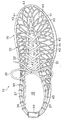
履物製品10は、アッパー20およびソール構造30を含むように図1〜4に示されている。以下の本文での参照のために、履物10は、図1および2に示されているように、3つの一般的な領域、足前部(forefoot)領域11、足中部(midfoot)領域12、踵領域13に分割することができる。領域11〜13は、履物10の厳密な領域を区分するものではない。むしろ、領域11〜13は、以下の議論において履物10の一般的な領域を表すものである。領域11〜13は履物10に全体的に適用されるが、領域11〜13の参照は、アッパー20、ソール構造30、アッパー20またはソール構造30内の個々の構成要素にも具体的に適用される。
アッパー20は、ソール構造30に固定され、足を受け入れる空隙を形成している。参照のために、アッパー20は、外側側面21、反対側の内側側面22、および爪革領域23を含んでいる。外側側面21は、足の外側側面に沿って延びるように位置し、ほぼ各領域11〜13を通過している。同様に、内側側面22は、足の反対側の内側側面に沿って延びるように位置し、ほぼ各領域11〜13を通過している。爪革領域23は、足の上面に対応するように外側側面21と内側側面22の間に位置している。爪革領域23は、レース(lace)25を有するスロート(throat)24と、アッパー20の各寸法を修正し、それによって履物10のフィット感を調整するために従来どおりに利用される他の任意の閉鎖機構とを含んでいる。アッパー20は、足がアッパー20内の空隙に接近するのを可能にする足首開口部26も含んでいる。
The upper 20 is fixed to the
アッパー20は、踵要素48および爪先要素49も含んでいる。踵要素48は、履物10の履き心地を高めるように上向きにかつアッパー20の内面に沿って延びている。爪先要素49は、耐摩耗性を与えかつ足の位置決めを助けるために足前部領域11内およびアッパー20の外面上に配置されている。いくつかの態様では、たとえば、踵要素48および爪先要素49の一方または両方がなくてもよく、あるいは踵要素48を外面上に位置させることができる。
The upper 20 also includes a
ソール構造30は、アッパー20の下面に固定され、ミッドソール31、アウトソール32、および中敷き33を含む全般的に従来の構造を有している。ミッドソール31は、ウォーキング、ランニング、またはその他の歩行活動中に圧縮されて地面の反力を減衰させるポリウレタンまたはエチルビニルアセテートなどのポリマーフォーム材料で形成することができる。本発明のいくつかの局面では、ポリマーフォーム材料は、履物10の履き心地、運動制御能力、安定性、または地面反力減衰を向上させる、流体が充填された嚢またはモデレータなどの様々な要素を密閉するかまたは含んでよい。アウトソール32は、ミッドソール31の下面に固定され、歩行活動中に地面に接触するゴムなどの耐摩耗性材料で形成されている。アウトソール32を形成する材料は、牽引およびすべり抵抗を向上させるようにテクスチャ加工することができる。中敷き33は、履物10の履き心地を高めるようにアッパー20内の空隙内に足の下面に隣接して配置された薄く圧縮可能な部材である。上述のソール構造30の構成は履物10に適しているが、ソール構造30は、任意の従来のまたは従来以外のソール構造の構成を呈してよい。
The
アッパー20の少なくとも一部は、様々な交差部42でクロスする複数のセグメント41で形成されたマトリックス層40を含んでいる。セグメント41のこの構成は、マトリックスの構造を構成し、マトリックス層40に複数の孔43を形成する。本明細書では、「マトリックス」という語は、孔を形成する、たとえばネット、グリッド、格子、ウェブ、および有孔材料を含む様々な構成を包含するものである。マトリックス層40は、たとえばゴム、シリコーン、熱可塑性ポリウレタン、ポリプロピレン、ポリエチレン、エチルビニルアセテート、およびスチレンエチルブチレンスチレンを含むポリマー材料の単体(すなわち、一体)構成で形成することができる。ポリマー材料の硬度は、本発明の様々な局面の範囲内で様々な値をとることができるが、ショア(Shore)Aスケール上で98以下の硬度を有するポリマーは、マトリックス層40の心地よさおよび可とう性を向上させ、一方引き続き足を支持することができる。マトリックス層40を製造する際、後述のように射出成形プロセスによってポリマー材料を成形し、単体構成を形成することができる。しかし、代替として、各セグメント41に対応する個々の要素を交差部42で接合し、マトリックス層40の特性を有する構造を形成することができる。たとえば、個々のセグメント41を、マトリックス層40を形成するように互いに結合または接着することができる。さらに、マトリックス層40は、セグメント41、交差部42、および孔43をレーザー切断または打抜き(die)切断することができる。
At least a portion of the upper 20 includes a
マトリックス層40は、足に隣接して延びる心地よい柔軟な構造を形成している。以下に詳しく説明するように、マトリックス層40は、動きおよび足の寸法の差に適応するように延びている。すなわち、マトリックス層40の伸縮性によって、履物10は様々な寸法比率の足を受け入れることができ、マトリックス層40はアッパー20を軽量構造にすることもでき、孔43は比較的高い通気度を履物10に与えることができる。これらの利点は、以下の議論に示される内容に基づいてより明らかになろう。
The
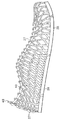
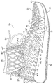
マトリックス層40は、図5に個別に示されている。参照のために、図5には、マトリックス層40のどの領域が外側側面21、内側側面22、および爪革領域23に相当するかを示す符番21〜23が示されている。マトリックス層40は概ね、中央領域(爪革領域23)および中央領域から延びる一対の側面領域(外側側面21および外側側面22)を含むU字形構成を有している。様々なセグメント41の末端は、マトリックス層40の周辺部を形成し、4つの縁部44a〜44dを形成している。縁部44aはマトリックス層40の最外縁部であり、縁部44bは縁部44aから間隔を置いて配置されており、縁部44cおよび44dはそれぞれ縁部44aおよび44b間を延びている。
The
マトリックス層40を履物10に組み込むと、縁部44aは、ソール構造30に隣接して位置し、ソール構造30に接合することができる。縁部44bの、中央領域に隣接して位置する部分はスロート24を形成し、縁部44bの、縁部44cおよび44dに隣接して位置する部分は足首開口部26を形成している。縁部44cおよび44dは、互いに踵領域13で接合され、ソール構造30と足首開口部26の間を鉛直に延びている。上記に指摘したように、様々なセグメント41の末端が縁部44a〜44dを形成している。各縁部44b〜44dに沿って、セグメント41の末端は、円形、楕円形、または他の任意の実際的な形状を有する複数のループ45を形成している。図1〜4に示されているように、コード(cord)27はループ45を通して延びており、コード27を利用して縁部44cおよび44dが互いに接合される。コード27がループ45を通して延びる際、ループ45はコード27を受け入れるように回転することができる。セグメント41の端部領域にループ45を形成すると、ループ45のこのような回転が容易になる。
When the
セグメント41同士が交差部42で互いに交差するかまたはそうでなければクロスすることができる。セグメント41の向きおよび全体的な位置は、孔43の形状に影響を与える。図1〜5に示されているように、孔43は、細長い四辺形の構成(たとえば、ダイヤモンド形の構成)を呈するように形成されている。特に、セグメント41の大部分は、縁部44aおよび44b間を延びるように向きを定められており、この向きによって、孔43は、縁部44aおよび44bに対して平行な方向よりも、縁部44aおよび44bに対して垂直な方向の方が長くなるように形成される。
The
セグメント41の向きおよび孔43の結果して得られる形状は、マトリックス層40の方向性伸び率(伸縮性)に影響を与える。上記に論じたように、孔43は、細長い四辺形の構成を有し、孔43は、縁部44aおよび44bに対して平行な方向よりも縁部44aおよび44bに対して垂直な方向の方が長い。この構成では、マトリックス層40は、縁部44aおよび44bに対して平行な方向の方が伸び率が高く、マトリックス層40は、縁部44aおよび44bに対して垂直な方向の方が伸び率が低い。したがって、マトリックス層40の伸縮度は、マトリックス層40が伸びる方向によって決まる。
The orientation of the
方向性伸び率の差は1つには、孔43の細長い四辺形の構成を形成する相対的な角度によるものである。図5を参照すると、様々な孔43が4つの角度46a〜46dを有する孔として参照されている。各角度46aは、角度46aの頂点が縁部44aの方を指すように向きを定められている。各角度46bは、角度46aと向かい合って位置し、角度46bの頂点が縁部44bの方を指すように向きが定められている。同様に、角度46cおよび46dは、互いに向かい合って位置し、角度46cおよび46dの頂点はそれぞれ、縁部44cおよび44dの方を指している。言い換えれば、角度46aおよび46bの頂点は縁部44aおよび44bに対して垂直な方向を指し、角度46cおよび46dの頂点は縁部44aおよび44bに対して平行な方向を指している。追加の点として、各交差部42は、各角度44a〜44dも形成している。
The difference in directional elongation is due in part to the relative angle that forms the elongated quadrilateral configuration of the
角度46aおよび46bは鋭角であるが、マトリックス層40が伸びていないか、または圧縮されていないか、または変形されていない状態であるときには角度46cおよび46dは鈍角である。ラジアン単位で言えば、角度46aおよび46bはそれぞれ、0.50πラジアンよりも小さい値を有し、角度46cおよび46dはそれぞれ、0.50πラジアンよりも大きい値を有している。特に、角度46aおよび46bは、0.25πラジアン(すなわち、45度)のラジアン測定値を有してよいが、たとえば0.01πラジアン〜0.49πラジアンの範囲であってよい。これに応じて、角度46cおよび46dは、0.75π(すなわち、135度)ラジアンのラジアン測定値を有してよいが、たとえば0.51πラジアン〜0.99πラジアンの範囲であってよい。マトリックス層40を伸ばすと、マトリックス層40が伸びる方向に基づいて各角度46a〜46dの相対ラジアン測定値が変化する。
マトリックス層40を縁部44aおよび44bに対して垂直な方向に伸ばすと、角度46aおよび46bのラジアン測定値が小さくなり、角度46cおよび46dのラジアン測定値が大きくなる。特に、縁部44aおよび44bに対して垂直な方向に引っ張り力を加えると、角度46aおよび46bのラジアン測定値が零に近づく。さらに引っ張り力を加えた場合、セグメント41の長さが伸びて引っ張り力に抵抗する。角度46aおよび46bが鋭角である場合、ラジアン測定値を零にするには角度46aおよび46bのラジアン測定値を比較的小さい角度に変更するだけでよい。
When the
逆に、マトリックス層40を縁部44aおよび44bに対して平行な方向に伸ばすと、角度46cおよび46dのラジアン測定値が小さくなり、角度46aおよび46bのラジアン測定値が大きくなる。特に、縁部44aおよび44bに対して平行な方向に引っ張り力を加えると、角度46cおよび46dのラジアン測定値が零に近づく。さらに引っ張り力を加えた場合、セグメント41の長さが伸びて引っ張り力に抵抗する。角度46cおよび46dが鈍角である場合、ラジアン測定値を零にするには角度46aおよび46bのラジアン測定値を比較的小さい角度に変更するだけでよい。
Conversely, when the
上記の議論に基づいて、引っ張り力を加えると角度46a〜46dのラジアン測定値が得られる。角度46aおよび46bのラジアン測定値と角度46cおよび46dのラジアン測定値の差は、特定の方向におけるマトリックス層40の伸び率に影響を与える。すなわち、角度46aおよび46bが鋭角であると、縁部44aおよび44bに対して垂直な方向の伸び率が比較的低くなる。しかし、角度46cおよび46dが鈍角であると、縁部44aおよび44bに対して平行な方向の伸び率が比較的高くなる。したがって、マトリックス層40は、縁部44aおよび44bに対して平行な方向で伸び率が高くなるように構成される。
Based on the above discussion, applying a tensile force results in radians measured at
方向性伸び率の差は、履物10に組み込まれると、履物10の全体的な履き心地および調整性に影響を与える。レース25を締め付けると、少なくともスロート24の領域において、縁部44aおよび44bに対して垂直な方向に効果的に引っ張り力が生じる。この方向に比較的低い伸縮度が与えられたと仮定すると、装着者は、ソール構造30に対して位置させた足を心地よくしかもしっかりと保持する程度にアッパー20を締め付けることができる。しかし、スロート24に隣接する領域では、マトリックス層40は依然として、縁部44aおよび44bに対して平行な方向に伸びることができる。したがって、歩行活動時には、マトリックス層40は、縁部44aおよび44bに対して平行な方向に伸びて、足のたわみまたはその他の動きに適応する。
The difference in directional elongation affects the overall comfort and adjustability of
マトリックス層40はまた、足前部領域11に心地よさを与える。足前部領域11では、縁部44aおよび44bに対して垂直な方向が履物10の長手方向に延びていることに留意されたい。したがって、マトリックス層40は、足前部領域11の長手方向では比較的低い伸縮度を有する。足前部領域11の縁部44aおよび44bに対して平行な方向では、マトリックス層40はより高い伸縮度を有する。したがって、マトリックス層40は、足の爪先および母指球を含む足前部の動きまたは寸法の変化に適応するように伸びる。たとえば、足は、踵が地面を離れ、中手指節間接がたわむように前方の回転し、足は、中手指節関節の所で内側方向から外側方向にわずかに膨張することができる。マトリックス層40が内側方向から外側方向に伸びると仮定すると、足のこのような動きは抑制されない。
The
引っ張り力を加えたときのマトリックス層40の伸縮度は、上述のように、少なくとも部分的に孔43の形状によって決まる。マトリックス層40の材料およびセグメント41の太さ(thickness)を含む他の因子もマトリックス層40の伸縮度に影響を与える。上記に列挙されたポリマー材料の多くについては、孔43の面積とセグメント41の面積との適切な比は少なくとも1.5:1であってよい。
The degree of expansion / contraction of the
上述のように、孔43は細長い四辺形の構成を有し、孔43は、縁部44aおよび44bに対して平行な方向よりも縁部44aおよび44bに対して垂直な方向の方が長い。いくつかの履物製品では、他の構成を有する孔43を形成すると有益である場合がある。図6Aを参照すると、孔43が、縁部44aおよび44bに対して垂直な方向よりも縁部44aおよび44bに対して平行な方向の方が長い、マトリックス層40の代替構成の一部が示されている。図6Bは、孔43が方形または細長い形状以外の形状を有する別の構成を示している。図6Cを参照すると、孔43が、丸い形状を有するように示されている。孔43は、図6Dに示されているように楕円形状を呈してもよい。いくつかの態様では、孔43は、図6Eおよび6Fに示されているように、六角形を有するように形成することができる。さらに、孔43は、図6Gおよび6Hに示されている形状に類似した形状を有してよい。したがって、孔43の形状は様々であってよい。
As described above, the
マトリックス層40は、アッパー20の大部分を形成するように図1〜3に示されている。しかし、本発明のさらなる局面では、アッパー20は、それぞれの異なる材料または材料のそれぞれの異なる組み合わせを有する複数の層を含んでよく、マトリックス層40は、少なくとも1つの層または少なくとも1つの層の一部を形成することができる。一例として、マトリックス層40の全体的な構成を有する要素を足前部領域11または踵領域13に限定することができ、アッパー20の残りの部分は別の構成を有してよい。さらに、ブーティーまたはソック(sock)を、足を受け入れ、かつ履物10が摩耗したときに足とマトリックス層40の間を延びるように、アッパー20内の空隙内に配置することができる。
The
様々なセグメント41の太さは実質的に一定であってよい。いくつかの態様では、セグメント41の太さは、セグメント41が縁部44aに隣接してより太い太さを有し、縁部44bに隣接してより細い太さを有するように縁部44aおよび44b間で徐々に細くなっていく。この太さは、踵領域13内のセグメント41が領域11および12内のセグメント41よりも細くなるように変化してもよい。セグメント41の断面形状も、たとえば円形、楕円形、方形、または三角形を含むように変化させてよい。断面は、楕円形または矩形で形成した場合、太さを上回る長さを有し、より長い表面を足に隣接して配置することができる。
The thickness of the
次に、図7A〜7Dを参照して、履物10を製造する方法について論じる。マトリックス層40は、図7Aに示されているようにポリマー材料から型50で単体(すなわち、一体)構成に形成することができる。型50は、上部51および下部52を含んでいる。図示のように、下部52の表面は、マトリックス層40の全体的な形状を有するくぼんだ領域53を含んでいる。代替として、上部51または部分51および52の両方が、マトリックス層40の形状のくぼんだ部分を有してよい。使用時には、部分51および52を互いに重なり合い接触する位置に配置し、くぼんだ領域53にポリマー材料を射出する。ポリマー材料が加硫または硬化した後、図7Aに示されているように、部分51および52を分離し、マトリックス層40を取り外す。
A method of manufacturing
マトリックス層40を型50から取り外す際、図7Bに示されているように、縁部44aに隣接してラスティング(lasting)要素28を固定する。ラスティング要素28は、マトリックス層40に接着剤によって固定することができる。しかし、マトリックス層40を熱可塑性ポリマーで形成する際、ボンディング(bonding)を使用してマトリックス層40をラスティング要素28に接合することができる。ラスティング要素28の適切な材料には、たとえば、織布・不織布を問わない繊維製品、またはポリマーシート材料が含まれる。代替として、ポリマー材料を射出する前にラスティング要素28を型50内に(すなわち、くぼんだ領域53内に)配置することができる。ポリマー材料を型50内に射出する際、ポリマー材料の一部がラスティング要素28に接触し、加硫するかまたはそうでなければ硬化するかあるいは重合され、それによってラスティング要素28がマトリックス層40に固定される。いくつかの態様では、マトリックス層40の一部がラスティング要素28に機械的に接合される密着構成を利用することができる。
When the
ラスティング要素28が縁部44aに固定された後、図7Cに示されているように、コード27をマトリックス層40に組み込む。上記に指摘したように、コード27は、ループ45を通して延び、縁部44cおよび44dを互いに接合するのに利用される。特に、コード27は、スロート24内のループ45を通し、足首開口部26に隣接するループ45を通し、縁部44cおよび44dを形成するループ45を通して延びる。コード27を組み込む前に、縁部44cおよび44dを互いに隣接させて配置する。次に、コード27は縁部44cおよび44dに沿ってループ45を通って延び、縁部44cおよび44dを互いに接合する。図7Cを見ると分かるように、このようにコード27をマトリックス層40に組み込むと、マトリックス層40がアッパー20の一般的な形状に形成され始める。さらに、この時点で踵要素48を組み込むことができる。1本のコード27を使用する代わりに、以下に詳しく論じるように2本以上のコード27を利用することができる。
After the
履物10を製造するプロセスにおけるさらなる段階を図7Dに示す。ここでは、レース25およびストロベル(strobel:登録商標)ソック29をマトリックス層40に接合する。コード27がループ45を通して延びると、少なくともスロート24において様々なセグメント41とコード27の間に孔が形成され、これらの孔にレース25を通すことができる。したがって、レース25を、スロート24を横切ってジグザグパターンを描いて延びるようにアッパー20に組み込むことができる。ストロベルソック29は、アッパー20内の空隙の下面を形成する。上述のように、ラスティング要素28を縁部44aに接合する。ストロベルソック29をマトリックス層40に接合する際、ストロベルソック29をラスティング要素28に縫い付けるか、接着剤で結合するか、またはそうでなければ接合することができる。次に、ソール構造30をアッパー20に接合して履物10の製造を事実上完了する。さらに、この時点で爪先要素49を組み込むことができる。いくつかの態様では、マトリックス層40またはラスティング要素28の一部をソール構造30に機械的に接合する密着構成を利用することができる。さらに、マトリックス層20が足前部領域11または踵領域13の周りを延びる領域では、図7Dに示されているようにラスティング要素28をまとめてこれらの領域におけるアッパー20の丸められた構成を容易にすることができる。すなわち、ラスティング要素28は、製造プロセス時にマトリックス層40をまとめるのを容易にする。
A further stage in the process of manufacturing the
従来の履物製品では、アッパーは特定のサイズを有する履物に適合するように形成される。たとえば、サイズ10用に形成されるアッパーはサイズ9.5用に形成されるアッパーよりも大きい。マトリックス層40を利用することの利点は、あるサイズのマトリックス層40を一連の履物サイズに使用できることである。たとえば、単一の型を利用して5つの実質的に同一のマトリックス層40を形成することができ、8から10までのサイズを有する個々の履物製品にマトリックス層40を組み込むことができる。上述のように、マトリックス層40は、縁部44aおよび44bに対して平行な方向で伸び率がより高くなるように構成される。マトリックス層40をアッパーに組み込む際に伸ばすことによって、連続的に大きくなるサイズを有する履物にマトリックス層40を組み込むことができる。状況によっては、マトリックス層40の圧縮を利用してマトリックス層40を連続的に小さくなる履物製品に組み込むことができる。すなわち、図8に示されているように、個々のマトリックス層40を、一連の足のサイズを受け入れるサイズの履物製品に組み込むことができる。
In conventional footwear products, the upper is formed to fit footwear having a particular size. For example, the upper formed for
個々のマトリックス層40を様々な履物サイズに利用することができる場合、履物10の製造効率が高くなる。個々のマトリックス層40を利用して右足または左足を受け入れるように履物10を形成することができる。図5に示されているように、マトリックス層40は、概ね対称的な構造を有し、したがって、右足または左足用の履物10に組み込むことができる。マトリックス層40が対称的ではない状況では、単に裏返すかまたはそうでなければマトリックス層40の向きを逆にすることによって、個々のマトリックス層40は右足または左足を受け入れることができる。したがって、マトリックス層40の1つの構成が右足用の履物10にも左足用の履物10にも適しているという点で、履物10の製造効率がさらに高められる。
If the individual matrix layers 40 can be used for various footwear sizes, the production efficiency of the
上述のように、マトリックス層40は、縁部44aおよび44bに対して垂直な方向よりも縁部44aおよび44bに対して平行な方向でより高い伸び率を有するように構成される。状況によっては、縁部44aおよび44bに対して平行な方向でより低い伸び率が必要とされる場合がある。縁部44aおよび44bに対して平行な方向の伸び率を変化させる一方法では、角度46a〜46dのラジアン測定値が修正される。しかし、これは縁部44aおよび44bに対して垂直な方向の伸び率も変化させるという効果を有する。縁部44aおよび44bに対して垂直な方向の伸び率を実質的に変化させずに縁部44aおよび44bに対して平行な方向の伸び率を変化させるために、図9Aに示されているように1つまたは複数の接続部材47を利用してもよい。接続部材47は、選択された孔43を二分し、角度44cから角度44dまで延びてこれらの孔43の伸縮度を制限する。
As described above, the
履物10は、上記では、単一のマトリックス層40を備えた履物として論じられている。図9Bを参照すると、一対のマトリックス層40が履物10に組み込まれている。一方のマトリックス層40はアッパー20の外面を形成し、他方のマトリックス層40はアッパー20の内面を形成している。すなわち、各マトリックス層は、同一の広がりを呈し、履物10の外面および内面を交互に形成している。各マトリックス層40は同じ材料で形成することができる。代替として、たとえば、外面を形成するマトリックス層40を、耐摩耗性を有する材料として選択された材料で形成することができ、内面を形成するマトリックス層40を、履き心地を良くする材料または(たとえば、装着者が履物10を裸足で履くのを可能にするために)触覚特性を向上させた材料として選択された材料で形成することができる。したがって、マトリックス層40はそれぞれ、協働して履物10に有益な特性をもたらす様々な材料で形成することができる。
履物10は、図1〜3では、足首開口部26が足首の下部領域の周りを延びる構成を有するように示されている。しかし、図9Cでは、履物10は、ユーザの足首の周りを延び、足首開口部26の位置を足首の上部領域まで上昇させる延長マトリックス40'を含むように示されている。図示のように、延長マトリックス40'は、ループ45に類似しており、かつコード27を受け入れ、それによって延長マトリックス40'を履物10に接合する様々なループ45'を含んでいる。コード27は、上向きに延び、踵領域13の背面に沿って延長マトリックス40'の縁部同士を接合しており、レース25は延長マトリックス40'の前部に沿って延びている。コード27およびレース25のそれぞれを調整することによって、マトリックス層40'を足首の周りに嵌める方法を修正することができる。延長マトリックス40'は、上記では、マトリックス層40から分離された要素として論じられている。しかし、いくつかの態様では、延長マトリックス層40'をマトリックス層40を有する単体構成で形成することができる。
The
上記にマトリックス層40に関して論じたように、コード27はループ45を通して延びており、少なくともスロート24における様々なセグメント41とコード27の間に孔が形成されている。この場合、これらの孔にレース25を通すことができる。同様の構成を延長マトリックス40'に利用することができる。代替として、図9Cに示されているように、レース25は直接ループ45'を通して延びることができる。したがって、ループ45および/またはループ45'は、コード27ではなくレース25を受け入れ、レーシングシステムを形成することができる。
As discussed above with respect to the
図9Cの履物10の追加の特徴は、側面21および22の各々上ならびに足前部領域11と足中部領域12の接合部に配置された安定性マトリックス40''に関する。安定性マトリックス40''は、マトリックス層40の一部と重なり合い、足の側面の安定性を高める。図示のように、安定性マトリックス40''は、概ね三角形状を有するが、本発明の範囲内の様々な形状を有してよい。安定性マトリックス40''は、足前部領域11と足中部領域12の接合部に位置するように示されているが、同様の要素を履物10の他の領域に配置することができる。安定性マトリックス40''はソール構造30の外部に固定されるように示されているが、安定性マトリックス40''は他の位置に固定することもできる。
An additional feature of the
上記に論じたように、セグメント41の太さは、マトリックス層40の伸縮度に影響を与える。履物10の横方向安定性を向上させるには、図9Dに示されているようにセグメント41の太さを選択的に太くし、横方向運動時の安定性を高めることができる。図示のように、踵領域13および足中部領域12の一部内のセグメント41は、より太い太さを呈している。さらに、安定性マトリックス40''に関連するセグメントもより太い太さを呈する。いくつかの態様では、マトリックス層40の他の領域および延長マトリックス40'の一部は、より太い太さを呈してよい。したがって、より太いセグメント41を履物10の任意の領域に利用して安定性を高めることができる。
As discussed above, the thickness of the
バスケットボールなどのスポーツ時において、横方向への運動時には踵の安定性がより高いと有益である。セグメント41の太さを太くすることは、安定性を高める一方法を構成する。この方法の他にまたはこの方法と組み合わせて、図9Eに示されているように、アッパー20に補強構造60を組み込むことができる。特に、補強構造60を、踵領域13の周りを延び、かつ安定性を高めるように、ソール構造30およびマトリックス層40の外部に固定することができる。さらなる態様では、他の構成の補強構造60を足中部領域12に配置して足のアーチを支持するか、または他の構成の補強構造60を足前部領域11に配置することができる。したがって、様々な補強構造をアッパー20に組み込んで安定性を高めることができる。
In sports such as basketball, it is beneficial if the stability of the kite is higher when exercising laterally. Increasing the thickness of the
上記に図9C〜9Eに関して論じた様々な概念を他の構成の履物10に適用することもできる。図9Fを参照すると、たとえばランニング、テニス、またはクロストレーニングに適した構成を有する履物10に安定性マトリックス40''が組み込まれている。さらに、プレート状構成を有する補強構造60'が踵領域13に組み込まれている。
Various concepts discussed above with respect to FIGS. 9C-9E can also be applied to other configurations of
1本のコード27を使用する代わりに2本以上のコード27を利用することができる。図10Aを参照すると、第1のコード27'は、スロート24内のループ45および足首開口部26に隣接するループ45を通して延びることができる。縁部44cおよび44dを形成するループ45を通して第2のコード27''が延びることもできる。さらに、第2のコード27''は、踵要素48に固定され、第2のコード27''を締め付けて第2のコード27''の相対的な位置を保持する固定具48'を通して延びている。この構成では、2本のコード27'および27''を、履物10のフィット感を向上させるようにそれぞれ独立に調整することができる。たとえば、ユーザは、図10Bに示されているように、コード27''の上部を引き上げて締め付け、踵領域13のフィット感を向上させることができる。同様に、ユーザは、第2のコード27''を緩めて踵領域13に追加的な体積を形成することができる。実際、第2のコード27''を締め付け緩めると、縁部44cおよび44dの相対的な位置が移動して(すなわち、縁部44cおよび44d間の空間が小さくなるかまたは大きくなって)踵領域13のフィット感が調整される。いくつかの態様では、縁部44cに沿ったループ45を、縁部44dに沿ってループ45を通して延び縁部44cおよび44dを接合する突起で形成することができる。したがって、コード27以外の構造を利用して縁部44cおよび44dを接合することができる。
Instead of using one
履物10が摩耗し、マトリックス層40が足または足の周りを延びるソックのすぐ隣に位置することがある。いくつかの態様では、図11に示されているように、マトリックス層40と足の間をライナー70が延びることができる。ライナー70は一般に、アッパー20内に形成された空隙の形状に対応する形状を有している。履物10の安定性を高めるために、ライナー70を形成する繊維製品材料は、半剛性の支持体72を受け入れる様々なポケット71を有してよい。ポケット71および支持体72は、概ね鉛直方向に延びて足首の内側および外側に沿って支持することができる。または、支持体72は足首の周りを延びるかもしくは足に隣接して延びることができる。
The
アッパー20とライナー70の間の顕著な移動を防止するために、ライナー70の下面に固定具73を組み込んでよく、アッパー20の内部に対応する固定具を組み込んでよい。たとえば、固定具73がフック・ループ固定システムのフック部である場合、ループ部をアッパー20内に位置させることができる。固定具73は、ライナー70の下面およびアッパー20内の空隙の下面上に配置された、ネオプレン(登録商標)などの非滑り材料であってもよい。ライナー70をアッパー20内に配置すると、固定具73は、アッパー20に対するライナー70のさらなる移動を効果的に制限し、それによって足をしっかりと位置決めする。固定具73のフック・ループ固定システムの代わりに、たとえばスナップ、ボタン、および接着剤を含む他の種類の固定システムを利用することができる。さらに、固定具73の位置は、側面および裏面を含む、ライナー70の下面以外の位置を含む様々な位置のいずれであってもよい。したがって、固定具の種類および位置は様々であってよい。
In order to prevent significant movement between the upper 20 and the
ライナー70は一般に、履物10の履き心地を向上させる。ある移動時には、マトリックス層40の一部が足に圧力を加えることがあり、ライナー70は足の広い領域にわたって圧力を分散させる働きを有する。ライナー70にフォーム材料を組み込んで履き心地をさらに向上させることができ、ライナー70の材料は、足を冷却し汗の消散を可能にするように通気性であってもよい。ライナー70を形成する材料は、防水性または耐水性であってもよい。
The
コード27がループ45を通して延びる際、ループ45は捩れるかまたはそうでなければ回転してコード27に適応することができる。マトリックス層40を形成する材料は、この回転に適応するのに十分な程度の可とう性を有してよいが、この回転はマトリックス層40の材料へのさらなる応力を生じさせる。図12を参照すると、マトリックス層40は、ループ45が捩れるかまたは回転した構造を有するように形成される構成を有するように示されている。図5では、ループ45は、マトリックス層40の残りの部分と同一平面を形成している。これに対して、図12は、ループ45がマトリックス層40の残りの部分に対して傾斜した構成を示している。すなわち、ループ45は、コード27を追加的に著しく捻るかまたは回転させる必要無しにコード27に適応する、捩れるかまたはそうでなければ回転した構成を有するように形成されている。図12では、ループ45は、マトリックス層40の残りの部分に対して45度の角度に傾斜するように示されているが、さらなる構成では5度〜90度の範囲であってよい。
As the
本発明は、上記および添付の図面に様々な態様を参照して開示される。しかし、この開示によって満たされる目的は、本発明の各局面に関する様々な特徴および概念の一例を示すことであり、本発明の各局面の範囲を限定することではない。当業者には、添付の特許請求の範囲によって定義される本発明の範囲から逸脱せずに上述の各態様に多数の変形および修正を施しうることが認識されよう。 The present invention is disclosed above and in the accompanying drawings with reference to various embodiments. However, the objective met by this disclosure is to illustrate an example of various features and concepts relating to each aspect of the invention and is not intended to limit the scope of each aspect of the invention. Those skilled in the art will recognize that numerous variations and modifications can be made to the embodiments described above without departing from the scope of the invention as defined by the appended claims.
Claims (36)
アッパーに固定されたソール構造とを含む、履物製品。Including a matrix structure extending along at least one of the inside and outside of the footwear, the matrix structure being formed from a single polymer element and formed from a plurality of segments that cross each other to define a plurality of intersections and holes , At least some of the intersections each define a first angle and a second angle, wherein the first angle is an acute angle oriented in a substantially vertical direction, and the second angle is substantially An obtuse angle oriented in a horizontal direction, so that the matrix structure has a greater elongation in the longitudinal direction compared to the elongation in the direction perpendicular to the longitudinal direction, to accommodate differences in foot movement and foot dimensions An upper that is stretchable;
A footwear product comprising a sole structure secured to the upper.
アッパーに固定されたソール構造とを含む、履物製品。A matrix structure defining a first edge and an opposite second edge, wherein the matrix structure is formed from a single polymer element and between the first edge and the second edge. Formed from a plurality of elongated segments extending, the segments defining a plurality of intersections and holes, where the intersections are the points where the two segments cross each other, and the holes are the areas between the segments, the intersections At least a portion defines a first angle pair and a second angle pair, the first angle pair being oriented in a direction substantially perpendicular to the first edge and the second edge. was an acute angle, the second angle pairs, obtuse directed in a direction substantially parallel to the first edge and the second edge, the matrix structure, the longitudinal direction The elongation in the longitudinal direction is larger than the elongation in the vertical direction. And a stretchable to accommodate differences in the dimensions of the foot movement and foot, and the upper,
A footwear product comprising a sole structure secured to the upper.
Applications Claiming Priority (5)
| Application Number | Priority Date | Filing Date | Title |
|---|---|---|---|
| US69233605P | 2005-06-20 | 2005-06-20 | |
| US60/692,336 | 2005-06-20 | ||
| US11/340,409 US7540097B2 (en) | 2005-06-20 | 2006-01-26 | Article of footwear having an upper with a matrix layer |
| US11/340,409 | 2006-01-26 | ||
| PCT/US2006/023953 WO2007002068A2 (en) | 2005-06-20 | 2006-06-20 | Article of footwear having an upper with a matrix layer |
Related Child Applications (1)
| Application Number | Title | Priority Date | Filing Date |
|---|---|---|---|
| JP2012095309A Division JP5558515B2 (en) | 2005-06-20 | 2012-04-19 | Footwear products having an upper with a matrix layer |
Publications (2)
| Publication Number | Publication Date |
|---|---|
| JP2008543452A JP2008543452A (en) | 2008-12-04 |
| JP5147690B2 true JP5147690B2 (en) | 2013-02-20 |
Family
ID=37074922
Family Applications (2)
| Application Number | Title | Priority Date | Filing Date |
|---|---|---|---|
| JP2008517224A Active JP5147690B2 (en) | 2005-06-20 | 2006-06-20 | Footwear products having an upper with a matrix layer |
| JP2012095309A Active JP5558515B2 (en) | 2005-06-20 | 2012-04-19 | Footwear products having an upper with a matrix layer |
Family Applications After (1)
| Application Number | Title | Priority Date | Filing Date |
|---|---|---|---|
| JP2012095309A Active JP5558515B2 (en) | 2005-06-20 | 2012-04-19 | Footwear products having an upper with a matrix layer |
Country Status (6)
| Country | Link |
|---|---|
| US (2) | US7540097B2 (en) |
| EP (1) | EP1903898B1 (en) |
| JP (2) | JP5147690B2 (en) |
| CN (1) | CN101267752B (en) |
| BR (1) | BRPI0611986A2 (en) |
| WO (1) | WO2007002068A2 (en) |
Families Citing this family (83)
| Publication number | Priority date | Publication date | Assignee | Title |
|---|---|---|---|---|
| US7752775B2 (en) | 2000-03-10 | 2010-07-13 | Lyden Robert M | Footwear with removable lasting board and cleats |
| US6785985B2 (en) * | 2002-07-02 | 2004-09-07 | Reebok International Ltd. | Shoe having an inflatable bladder |
| US8677652B2 (en) | 2002-07-02 | 2014-03-25 | Reebok International Ltd. | Shoe having an inflatable bladder |
| US8065818B2 (en) * | 2005-06-20 | 2011-11-29 | Nike, Inc. | Article of footwear having an upper with a matrix layer |
| US8020319B1 (en) * | 2005-11-29 | 2011-09-20 | Anne Elizabeth Mohaupt | Shoe with elastic bindings to receive interchangeable straps |
| US8312646B2 (en) * | 2006-05-25 | 2012-11-20 | Nike, Inc. | Article of footwear incorporating a tensile element |
| US8122616B2 (en) * | 2008-07-25 | 2012-02-28 | Nike, Inc. | Composite element with a polymer connecting layer |
| US8051585B2 (en) * | 2008-11-06 | 2011-11-08 | Nike, Inc. | Article of footwear comprising a plurality of strips |
| US8132340B2 (en) * | 2009-04-07 | 2012-03-13 | Nike, Inc. | Footwear incorporating crossed tensile strand elements |
| US8935861B2 (en) * | 2009-08-14 | 2015-01-20 | Nike, Inc. | Article of footwear accommodating different foot sizes |
| DE102009028627B4 (en) * | 2009-08-18 | 2019-12-19 | Adidas Ag | Sports Shoe |
| US20120204450A1 (en) * | 2009-10-19 | 2012-08-16 | Wurzburg Holding S.A. | Easy-to-wear lace up article of footwear |
| FR2952279B1 (en) * | 2009-11-06 | 2011-11-25 | Joubert Productions | ANTI-SLIP SHOE |
| US8973288B2 (en) | 2010-07-30 | 2015-03-10 | Nike, Inc. | Footwear incorporating angled tensile strand elements |
| US8595878B2 (en) * | 2010-08-02 | 2013-12-03 | Nike, Inc. | Method of lasting an article of footwear |
| US8789295B2 (en) * | 2011-02-08 | 2014-07-29 | Wolverine World Wide, Inc. | Footwear and related method of manufacture |
| ES2702308T3 (en) * | 2012-02-04 | 2019-02-28 | Puma SE | Shoe, in particular sports shoe |
| US8887410B2 (en) | 2012-02-24 | 2014-11-18 | Nike, Inc. | Articles of footwear with tensile strand elements |
| WO2013136514A1 (en) * | 2012-03-16 | 2013-09-19 | 株式会社アシックス | Lace-up fitting structure |
| US8919776B2 (en) | 2012-04-24 | 2014-12-30 | Bbc International Llc | Article of footwear with maze |
| TWM438140U (en) | 2012-06-05 | 2012-10-01 | Joy Sewing King & World Prosperity Co Ltd | Garment modeling shoe body |
| DE212012000278U1 (en) * | 2012-06-20 | 2015-01-27 | CosmoCare Ltd. | clothing |
| EP2916677B1 (en) * | 2012-11-09 | 2020-01-08 | Fuerst Group, Inc. | Footwear article having cord structure |
| US9861160B2 (en) * | 2012-11-30 | 2018-01-09 | Nike, Inc. | Article of footwear incorporating a knitted component |
| US9826799B2 (en) * | 2013-03-14 | 2017-11-28 | Nike, Inc. | Uppers and articles incorporating same |
| US10299531B2 (en) | 2013-05-14 | 2019-05-28 | Nike, Inc. | Article of footwear incorporating a knitted component for a heel portion of an upper |
| US10306946B2 (en) * | 2013-05-14 | 2019-06-04 | Nike, Inc. | Article of footwear having heel portion with knitted component |
| JP5931800B2 (en) * | 2013-05-31 | 2016-06-08 | 真▲線▼情寰榮有限公司 | Clothing shoe body and manufacturing method thereof |
| BR112015032164A2 (en) | 2013-06-25 | 2020-03-31 | Nike Innovate Cv | footwear with braided upper |
| US10863794B2 (en) * | 2013-06-25 | 2020-12-15 | Nike, Inc. | Article of footwear having multiple braided structures |
| US20150059209A1 (en) | 2013-08-29 | 2015-03-05 | Nike, Inc. | Article Of Footwear Incorporating A Knitted Component With An Integral Knit Ankle Cuff |
| CN103462300A (en) * | 2013-09-18 | 2013-12-25 | 河南星智发明电子科技有限公司 | Shoes special for riding long-distance bus |
| JP5749774B2 (en) | 2013-09-30 | 2015-07-15 | 美津濃株式会社 | shoes |
| US10463106B2 (en) | 2014-02-13 | 2019-11-05 | Nike, Inc. | Sole assembly with textile shell and method of manufacturing same |
| US20150272274A1 (en) | 2014-03-25 | 2015-10-01 | Under Armour, Inc. | Footwear including textile element |
| US9763495B2 (en) | 2014-04-11 | 2017-09-19 | Asics Corporation | Upper of shoe |
| US9474326B2 (en) * | 2014-07-11 | 2016-10-25 | Nike, Inc. | Footwear having auxetic structures with controlled properties |
| US9668544B2 (en) | 2014-12-10 | 2017-06-06 | Nike, Inc. | Last system for articles with braided components |
| US10674791B2 (en) | 2014-12-10 | 2020-06-09 | Nike, Inc. | Braided article with internal midsole structure |
| CN107105813B (en) * | 2015-01-20 | 2020-11-03 | 耐克创新有限合伙公司 | Article of footwear with mesh structure |
| US9474331B2 (en) * | 2015-02-03 | 2016-10-25 | Nike, Inc. | Method of making an article of footwear having printed structures |
| TWI620517B (en) * | 2015-05-15 | 2018-04-11 | 耐克創新有限合夥公司 | Article of footwear incorporating a curved knitted lacing element and method of forming an upper of an article of footwear having a knitted component |
| US20160345675A1 (en) | 2015-05-26 | 2016-12-01 | Nike, Inc. | Hybrid Braided Article |
| US10555581B2 (en) | 2015-05-26 | 2020-02-11 | Nike, Inc. | Braided upper with multiple materials |
| US10238178B2 (en) * | 2015-06-17 | 2019-03-26 | Nike, Inc. | Expandable support member for an article of footwear |
| US9888743B2 (en) | 2015-06-17 | 2018-02-13 | Nike, Inc. | Reinforcement component for an article of footwear |
| US20170020231A1 (en) * | 2015-07-20 | 2017-01-26 | Nike, Inc. | Article of Footwear Having A Chain-Linked Tensile Support Structure |
| US11103028B2 (en) | 2015-08-07 | 2021-08-31 | Nike, Inc. | Multi-layered braided article and method of making |
| WO2017061002A1 (en) * | 2015-10-08 | 2017-04-13 | 株式会社アシックス | Shoe having upper and sole |
| CN108135317B (en) * | 2015-10-23 | 2021-02-09 | 彪马欧洲股份公司 | Shoes with removable sole |
| DE102015220865A1 (en) * | 2015-10-26 | 2017-04-27 | Adidas Ag | Shoeupper |
| EP3386331B1 (en) * | 2015-12-07 | 2020-07-29 | Nike Innovate C.V. | Article of footwear with tubular structures having tab portions |
| WO2017127443A1 (en) * | 2016-01-19 | 2017-07-27 | Nike Innovate C.V. | Three-dimensional printing of a multilayer upper |
| CN106974354B (en) | 2016-01-19 | 2021-02-09 | 富尔斯特集团有限公司 | Shoes with rope structure |
| US20170238655A1 (en) * | 2016-02-22 | 2017-08-24 | Terry Pineda | Nonslip Shower Footwear |
| CN105639824B (en) * | 2016-03-28 | 2017-11-28 | 联想(北京)有限公司 | A kind of material and Wearable |
| US10034519B2 (en) | 2016-06-16 | 2018-07-31 | Adidas Ag | UV curable lattice microstructure for footwear |
| CN106073026B (en) * | 2016-08-01 | 2018-12-25 | 东莞疆皓塑胶制品有限公司 | Shoes with eyelet structure |
| US10806210B2 (en) | 2017-05-31 | 2020-10-20 | Nike, Inc. | Braided articles and methods for their manufacture |
| US11202483B2 (en) | 2017-05-31 | 2021-12-21 | Nike, Inc. | Braided articles and methods for their manufacture |
| US11051573B2 (en) | 2017-05-31 | 2021-07-06 | Nike, Inc. | Braided articles and methods for their manufacture |
| CN110691529B (en) * | 2017-06-27 | 2022-05-27 | 彪马欧洲股份公司 | Shoe, in particular sports shoe |
| WO2019046390A1 (en) | 2017-08-31 | 2019-03-07 | Nike Innovate C.V. | Articles of footwear and other foot-receiving devices |
| DE102017008834B4 (en) * | 2017-09-20 | 2022-06-30 | Adidas Ag | Shoe with adaptive heel element |
| USD893852S1 (en) | 2018-03-30 | 2020-08-25 | Fuerst Group, Inc. | Footwear article |
| US10874172B2 (en) | 2018-04-04 | 2020-12-29 | Adidas Ag | Articles of footwear with uppers comprising a wound component and methods of making the same |
| USD883639S1 (en) | 2018-04-10 | 2020-05-12 | Lacrosse Footwear, Inc. | Shoe |
| USD883640S1 (en) | 2018-04-10 | 2020-05-12 | Lacrosse Footwear, Inc. | Shoe |
| EP3781737A1 (en) * | 2018-04-16 | 2021-02-24 | Nike Innovate C.V. | A shoe upper comprising knitted cushion regions and an article of footwear incorporating same |
| CN113163896B (en) * | 2018-11-20 | 2023-07-28 | 伊科斯克有限公司 | 3D prints structure |
| CN109512083A (en) * | 2018-12-27 | 2019-03-26 | 特步(中国)有限公司 | A kind of Novel spider plant drawing shoes |
| AU2019420589B2 (en) * | 2019-01-07 | 2021-05-13 | Fast Ip, Llc | Rapid-entry footwear having a compressible lattice structure |
| USD908322S1 (en) | 2019-05-14 | 2021-01-26 | Lacrosse Footwear, Inc. | Boot |
| USD932762S1 (en) | 2019-07-23 | 2021-10-12 | Puma SE | Shoe |
| USD935760S1 (en) | 2019-07-23 | 2021-11-16 | Puma SE | Shoe |
| USD918546S1 (en) * | 2019-08-16 | 2021-05-11 | Nike, Inc. | Shoe |
| US20210177095A1 (en) * | 2019-12-17 | 2021-06-17 | Under Armour, Inc. | Article of Footwear with Braided Upper |
| US11439206B2 (en) | 2019-12-17 | 2022-09-13 | Under Armour, Inc. | Method of making an article of footwear with braided upper |
| CA3162828A1 (en) * | 2019-12-26 | 2021-07-01 | Lululemon Athletica Canada Inc. | Footwear upper comprising stretch zones |
| WO2021127775A1 (en) * | 2019-12-26 | 2021-07-01 | Lululemon Athletica Canada Inc. | Footwear upper comprising stretch zones |
| US11602196B2 (en) * | 2020-07-13 | 2023-03-14 | Adidas Ag | Articles of footwear comprising a wound component and methods of making the same |
| USD943955S1 (en) * | 2020-08-26 | 2022-02-22 | Nike, Inc. | Shoe |
| US20220110416A1 (en) * | 2020-10-09 | 2022-04-14 | Nike, Inc. | Upper for Article of Footwear |
Family Cites Families (40)
| Publication number | Priority date | Publication date | Assignee | Title |
|---|---|---|---|---|
| BE531033A (en) | ||||
| US1227981A (en) | 1916-12-30 | 1917-05-29 | Lucius M Tynes | Fish-cord shoe. |
| US1877080A (en) | 1930-05-28 | 1932-09-13 | Teshima Isago | Wading overshoe |
| US1958135A (en) | 1932-03-10 | 1934-05-08 | Int Shoe Co | Shoe |
| US2052753A (en) * | 1933-01-11 | 1936-09-01 | Claude H Daniels | Method of making a boot or shoe |
| US2350879A (en) * | 1934-08-24 | 1944-06-06 | Claude H Daniels | Shoe |
| US2069381A (en) | 1936-05-15 | 1937-02-02 | Charles K Morgan | Shoe and means for decorating same |
| US2119392A (en) * | 1937-11-30 | 1938-05-31 | Levin David | Shoe |
| US2188168A (en) * | 1938-09-03 | 1940-01-23 | Winkel Mabel | Shoe |
| US2185762A (en) | 1939-02-02 | 1940-01-02 | Raymond F Anderson | Footwear |
| US2596188A (en) | 1949-10-18 | 1952-05-13 | Parva Products Co | Footwear |
| USD164847S (en) | 1951-07-30 | 1951-10-16 | Jean Dronoff | Shoe |
| US2954617A (en) | 1957-05-23 | 1960-10-04 | Nikka Rubber Co Ltd | Footwear |
| JPS5429950Y2 (en) * | 1976-12-28 | 1979-09-21 | ||
| US4265032A (en) * | 1979-06-14 | 1981-05-05 | Betherb, Inc. | Expandable article of footwear |
| US4222183A (en) | 1979-10-29 | 1980-09-16 | Haddox Billy J | Athletic shoe |
| IT8121560V0 (en) | 1981-04-23 | 1981-04-23 | Nuova Zarine Costruzione Macch | FOOTWEAR WITH UPPER ZONALLY COVERED BY SYNTHETIC MATERIAL INJECTED STABLY JOINED TO THE CANVAS. |
| USD278947S (en) | 1984-11-15 | 1985-05-28 | Foldes Steven M | Shoe and the like |
| USD303729S (en) | 1986-09-11 | 1989-10-03 | Macasieb Rick G | Shower shoe |
| USD293968S (en) | 1986-12-23 | 1988-02-02 | Grendene S.A. | Shoe |
| USD293966S (en) | 1986-12-23 | 1988-02-02 | Grendene S.A. | Sandal |
| USD293964S (en) | 1986-12-23 | 1988-02-02 | Grendene S.A. | Shoe |
| US4858339A (en) * | 1987-01-10 | 1989-08-22 | Nippon Rubber Co., Ltd. | Composite rubber sheet material and sports shoe employing the same |
| US4813158A (en) | 1987-02-06 | 1989-03-21 | Reebok International Ltd. | Athletic shoe with mesh reinforcement |
| DE9213747U1 (en) | 1992-10-12 | 1992-12-03 | Ito Design Gmbh, 8500 Nuernberg, De | |
| JPH0638608U (en) * | 1992-10-29 | 1994-05-24 | 美津濃株式会社 | Athletic shoes |
| IT1274340B (en) | 1994-03-09 | 1997-07-17 | Nordica Spa | PROCEDURE FOR THE REALIZATION OF FOOTWEAR BY INJECTION OF PLASTIC MARERIAL AND FOOTWEAR OBTAINED BY THAT PROCEDURE |
| WO1998043506A1 (en) | 1997-03-28 | 1998-10-08 | Fila U.S.A., Inc. | Engineered textile |
| USD401051S (en) | 1998-03-03 | 1998-11-17 | Hawe Yue, Inc. | Shoe upper |
| US6401364B1 (en) * | 2000-06-15 | 2002-06-11 | Salomon S.A. | Ventilated shoe |
| US6665954B2 (en) | 2002-02-05 | 2003-12-23 | Eddie Chen | Breathable rubber boot |
| US6931762B1 (en) * | 2002-12-18 | 2005-08-23 | Nike, Inc. | Footwear with knit upper and method of manufacturing the footwear |
| DE10300012A1 (en) * | 2003-01-02 | 2004-07-22 | W.L. Gore & Associates Gmbh | Waterproof footwear with an elastic connecting band |
| FR2853819B1 (en) | 2003-04-16 | 2005-07-08 | Marquet Et Cie | METHOD FOR MANUFACTURING RODS OF FOOTWEAR ARTICLES AND FOOTWEAR ARTICLES THUS OBTAINED |
| US7065820B2 (en) * | 2003-06-30 | 2006-06-27 | Nike, Inc. | Article and method for laser-etching stratified materials |
| US6990755B2 (en) * | 2003-10-09 | 2006-01-31 | Nike, Inc. | Article of footwear with a stretchable upper and an articulated sole structure |
| USD498583S1 (en) * | 2004-04-06 | 2004-11-23 | Nike, Inc. | Portion of a shoe upper |
| US7793434B2 (en) | 2004-09-03 | 2010-09-14 | Nike, Inc. | Article of footwear having an upper with a structured intermediate layer |
| US8192828B2 (en) | 2004-12-06 | 2012-06-05 | Nike, Inc. | Material formed of multiple links and method of forming same |
| EP1976405B1 (en) * | 2006-01-24 | 2016-09-21 | NIKE Innovate C.V. | Skateboard shoe with textured surface |
-
2006
- 2006-01-26 US US11/340,409 patent/US7540097B2/en active Active
- 2006-06-20 CN CN2006800263316A patent/CN101267752B/en active Active
- 2006-06-20 BR BRPI0611986-7A patent/BRPI0611986A2/en active Search and Examination
- 2006-06-20 EP EP06785173.3A patent/EP1903898B1/en active Active
- 2006-06-20 JP JP2008517224A patent/JP5147690B2/en active Active
- 2006-06-20 WO PCT/US2006/023953 patent/WO2007002068A2/en active Application Filing
-
2009
- 2009-05-11 US US12/463,881 patent/US7774884B2/en active Active
-
2012
- 2012-04-19 JP JP2012095309A patent/JP5558515B2/en active Active
Also Published As
| Publication number | Publication date |
|---|---|
| US7540097B2 (en) | 2009-06-02 |
| BRPI0611986A2 (en) | 2010-10-13 |
| US20090223004A1 (en) | 2009-09-10 |
| WO2007002068A3 (en) | 2007-05-10 |
| US20060283042A1 (en) | 2006-12-21 |
| JP2012161634A (en) | 2012-08-30 |
| US7774884B2 (en) | 2010-08-17 |
| CN101267752B (en) | 2010-05-19 |
| EP1903898A2 (en) | 2008-04-02 |
| EP1903898B1 (en) | 2014-03-26 |
| WO2007002068A2 (en) | 2007-01-04 |
| JP2008543452A (en) | 2008-12-04 |
| JP5558515B2 (en) | 2014-07-23 |
| CN101267752A (en) | 2008-09-17 |
Similar Documents
| Publication | Publication Date | Title |
|---|---|---|
| JP5147690B2 (en) | Footwear products having an upper with a matrix layer | |
| US10264854B2 (en) | Article of footwear having an upper with a matrix layer | |
| US20210015201A1 (en) | Foot Support Members That Provide Dynamically Transformative Properties | |
| CN108125306B (en) | Flexible sole and upper for an article of footwear | |
| TWI664923B (en) | Footwear having auxetic structures with controlled properties | |
| JP6529008B2 (en) | Footwear incorporating a knit component | |
| CN104507345B (en) | Fluid-filled chamber with robust structure | |
| TWI615104B (en) | Article of footwear incorporating a knitted component for a heel portion of an upper | |
| CN107427103A (en) | Auxetic sole with corresponding inside liner or outer lining |
Legal Events
| Date | Code | Title | Description |
|---|---|---|---|
| A131 | Notification of reasons for refusal |
Free format text: JAPANESE INTERMEDIATE CODE: A131 Effective date: 20110105 |
|
| A601 | Written request for extension of time |
Free format text: JAPANESE INTERMEDIATE CODE: A601 Effective date: 20110404 |
|
| A602 | Written permission of extension of time |
Free format text: JAPANESE INTERMEDIATE CODE: A602 Effective date: 20110411 |
|
| A521 | Request for written amendment filed |
Free format text: JAPANESE INTERMEDIATE CODE: A523 Effective date: 20110627 |
|
| A711 | Notification of change in applicant |
Free format text: JAPANESE INTERMEDIATE CODE: A711 Effective date: 20110805 |
|
| A131 | Notification of reasons for refusal |
Free format text: JAPANESE INTERMEDIATE CODE: A131 Effective date: 20111219 |
|
| A601 | Written request for extension of time |
Free format text: JAPANESE INTERMEDIATE CODE: A601 Effective date: 20120316 |
|
| A602 | Written permission of extension of time |
Free format text: JAPANESE INTERMEDIATE CODE: A602 Effective date: 20120326 |
|
| A521 | Request for written amendment filed |
Free format text: JAPANESE INTERMEDIATE CODE: A523 Effective date: 20120419 |
|
| TRDD | Decision of grant or rejection written | ||
| A01 | Written decision to grant a patent or to grant a registration (utility model) |
Free format text: JAPANESE INTERMEDIATE CODE: A01 Effective date: 20121126 |
|
| A61 | First payment of annual fees (during grant procedure) |
Free format text: JAPANESE INTERMEDIATE CODE: A61 Effective date: 20121127 |
|
| R150 | Certificate of patent or registration of utility model |
Ref document number: 5147690 Country of ref document: JP Free format text: JAPANESE INTERMEDIATE CODE: R150 Free format text: JAPANESE INTERMEDIATE CODE: R150 |
|
| FPAY | Renewal fee payment (event date is renewal date of database) |
Free format text: PAYMENT UNTIL: 20151207 Year of fee payment: 3 |
|
| S111 | Request for change of ownership or part of ownership |
Free format text: JAPANESE INTERMEDIATE CODE: R313113 |
|
| R360 | Written notification for declining of transfer of rights |
Free format text: JAPANESE INTERMEDIATE CODE: R360 |
|
| R360 | Written notification for declining of transfer of rights |
Free format text: JAPANESE INTERMEDIATE CODE: R360 |
|
| R371 | Transfer withdrawn |
Free format text: JAPANESE INTERMEDIATE CODE: R371 |
|
| S111 | Request for change of ownership or part of ownership |
Free format text: JAPANESE INTERMEDIATE CODE: R313113 |
|
| R350 | Written notification of registration of transfer |
Free format text: JAPANESE INTERMEDIATE CODE: R350 |
|
| R250 | Receipt of annual fees |
Free format text: JAPANESE INTERMEDIATE CODE: R250 |
|
| R250 | Receipt of annual fees |
Free format text: JAPANESE INTERMEDIATE CODE: R250 |
|
| R250 | Receipt of annual fees |
Free format text: JAPANESE INTERMEDIATE CODE: R250 |
|
| R250 | Receipt of annual fees |
Free format text: JAPANESE INTERMEDIATE CODE: R250 |
|
| R250 | Receipt of annual fees |
Free format text: JAPANESE INTERMEDIATE CODE: R250 |
|
| R250 | Receipt of annual fees |
Free format text: JAPANESE INTERMEDIATE CODE: R250 |
|
| R250 | Receipt of annual fees |
Free format text: JAPANESE INTERMEDIATE CODE: R250 |
|
| R250 | Receipt of annual fees |
Free format text: JAPANESE INTERMEDIATE CODE: R250 |
|
| R250 | Receipt of annual fees |
Free format text: JAPANESE INTERMEDIATE CODE: R250 |