JP5144590B2 - Reflex shade - Google Patents
Reflex shade Download PDFInfo
- Publication number
- JP5144590B2 JP5144590B2 JP2009123295A JP2009123295A JP5144590B2 JP 5144590 B2 JP5144590 B2 JP 5144590B2 JP 2009123295 A JP2009123295 A JP 2009123295A JP 2009123295 A JP2009123295 A JP 2009123295A JP 5144590 B2 JP5144590 B2 JP 5144590B2
- Authority
- JP
- Japan
- Prior art keywords
- light source
- source lamp
- movable
- light
- reflecting
- Prior art date
- Legal status (The legal status is an assumption and is not a legal conclusion. Google has not performed a legal analysis and makes no representation as to the accuracy of the status listed.)
- Expired - Fee Related
Links
Images


Description
本発明は、照明器具の光源ランプの光を照射方向に反射させる反射笠に関する。 The present invention relates to a reflective shade that reflects light from a light source lamp of a lighting fixture in an irradiation direction.
ルームライト、ダウンライト、スポットライト、車両用ヘッドライト等の照明器具は、照射効率を向上させるために、光源ランプからの光を照射方向に反射させる反射面を有する反射笠が備え付けられている。 Lighting fixtures such as room lights, downlights, spotlights, and vehicle headlights are provided with a reflective shade having a reflective surface that reflects light from the light source lamp in the irradiation direction in order to improve the irradiation efficiency.
一般的な照明器具用の反射笠として、台形の反射板を複数組み合わせたものが知られている(例えば、特許文献1を参照)。 As a reflection shade for a general lighting fixture, a combination of a plurality of trapezoidal reflectors is known (see, for example, Patent Document 1).
特許文献1の反射笠は、台形の反射板を横方向に8枚つなぎ合わせ、笠状構造にした典型的な構造を有する。この反射笠は、天井から吊り下げ、下方を照らすようにした照明器具に使用される。
The reflective shade of
また、近年では、照明器具を様々なシチュエーションで効率よく使用するために、反射笠を構成する反射板を可動式とし、配光を制御可能とする反射笠も開発されている(例えば、特許文献2を参照)。 In recent years, in order to efficiently use lighting fixtures in various situations, a reflective shade that makes the reflective shade movable and can control light distribution has been developed (for example, patent literature). 2).
特許文献2の照明器具に使用される反射笠は、光源ランプが取り付けられるソケットを光軸に沿って前後方向に移動可能とし、当該ソケットの移動に合わせて複数の反射板を回動させることにより、反射板の反射曲率が変更できるように構成されている。ここで、ソケットの移動は、ソケットの後方に設けられた回転つまみを回転させ、当該回転つまみと共に回転するねじ棒を照明器具の固定ベース板に対して前後に移動させることで行われる。また、ソケットの移動に伴う複数の反射板の回動は、すべてが同じ動作で同時に行われる。 The reflective shade used in the lighting fixture of Patent Document 2 allows a socket to which a light source lamp is attached to be movable in the front-rear direction along the optical axis, and rotates a plurality of reflectors according to the movement of the socket. The reflection curvature of the reflector can be changed. Here, the movement of the socket is performed by rotating a rotary knob provided behind the socket and moving a screw rod that rotates together with the rotary knob back and forth with respect to the fixed base plate of the lighting fixture. In addition, the plurality of reflectors that rotate with the movement of the socket are all performed simultaneously with the same operation.
照明器具は、その設置形態として、天井から吊り下げる形態、天井や壁に直接取り付ける形態、天井や壁に穴を空けてそこに埋め込む形態等がある。これらの設置形態では、照明器具を設置すると、その後はそのままの状態で継続使用されることになる。従って、従来の照明器具では、光の照射方向を変更することはあまり想定されていなかった。 Lighting fixtures can be installed in a manner that hangs from the ceiling, a form that is directly attached to the ceiling or wall, a form in which a hole is made in the ceiling or wall, and is embedded therein. In these installation forms, when the lighting apparatus is installed, it is continuously used as it is. Therefore, in the conventional lighting fixtures, it has not been expected to change the light irradiation direction.
ところが、照明器具の照射対象が変わったり、照射対象が移動したりすると、光の照射範囲や照射方向も変更したい場合がある。 However, when the irradiation target of the lighting fixture is changed or the irradiation target is moved, there is a case where it is desired to change the light irradiation range and the irradiation direction.
これに関し、特許文献1の反射笠は、8枚の反射板が笠状構造に固定された典型的な従来タイプの反射笠であるため、基本的には、光源ランプからの光の反射方向を変更することはできない。特許文献1の反射笠を用いた照射器具において、仮に、光の照射方向を変更しようとすると、照明器具から反射笠を一旦取り外し、所望の角度で組まれた別の反射笠を再度照明器具に取り付けるという極めて面倒な作業をすることになる。しかし、このような作業を行うことは非現実的である。
In this regard, the reflecting shade of
一方、特許文献2の反射笠は、ソケットの移動に合わせて反射板を回動させることにより、反射板の反射曲率を変更することができる。従って、光の照射範囲を拡大したり、スポット光のように照射範囲を絞ったりすることは可能である。ところが、この反射笠において反射板を回動させるためには、上述したように、ソケットの後方に設けられた回転つまみを回転させ、当該回転つまみと共に回転するねじ棒を照明器具の固定ベース板に対して前後に移動させる必要がある。しかし、照射器具を一旦設置すると、ソケットの後方に手を伸ばして回転つまみを操作することは極めて困難である。特に、天井埋め込み型の照明器具では、設置後はソケットの後方にアクセスすることは実質的に不可能となる。 On the other hand, the reflection shade of patent document 2 can change the reflective curvature of a reflecting plate by rotating a reflecting plate according to the movement of a socket. Therefore, it is possible to expand the light irradiation range or narrow the irradiation range like spot light. However, in order to rotate the reflecting plate in the reflecting shade, as described above, the rotating knob provided behind the socket is rotated, and the screw rod that rotates together with the rotating knob is used as the fixed base plate of the lighting fixture. It is necessary to move back and forth. However, once the irradiation device is installed, it is extremely difficult to reach the back of the socket and operate the rotary knob. In particular, in a ceiling-embedded luminaire, it is substantially impossible to access the rear of the socket after installation.
また、特許文献2の反射笠では、複数の反射板がすべて同じ動作で同時に回動するため、光軸を中心とした照射範囲の拡大・縮小は可能であるが、照射範囲を移動させたり、照射範囲を特定の方向に拡大・縮小したりすることはできない。 Moreover, in the reflecting shade of Patent Document 2, since all of the plurality of reflecting plates rotate simultaneously in the same operation, the irradiation range around the optical axis can be enlarged or reduced, but the irradiation range can be moved, The irradiation range cannot be enlarged or reduced in a specific direction.
本発明は、上記問題点に鑑みてなされたものであり、その目的は、照明器具からの光の照射方向を容易に変更することを可能とし、且つ、照射対象の状態に応じて適切な照射範囲を設定することを可能とする照明器具用の反射笠を提供することにある。 The present invention has been made in view of the above-described problems, and the object thereof is to enable easy change of the irradiation direction of light from a lighting fixture, and appropriate irradiation according to the state of an irradiation target. An object of the present invention is to provide a reflective shade for a luminaire that allows the range to be set.
上記課題を解決するため第1,第2,第5の発明の反射笠は、
照明器具の光源ランプの光を照射方向に反射させる反射笠において、
前記光源ランプの光を反射させる反射面を有するとともに前記光源ランプを取り囲むように配置された複数の可動式反射板と、
前記光源ランプに対する前記複数の可動式反射板の夫々の角度を個別に変更する複数の角度変更機構と、を備え、
前記複数の可動式反射板の前記反射面の側に前記複数の角度変更機構の夫々の操作部が設けられている。
In order to solve the above problems, the reflective shades of the first, second and fifth inventions are:
In the reflective shade that reflects the light of the light source lamp of the lighting fixture in the irradiation direction ,
A plurality of movable reflectors having a reflecting surface for reflecting the light of the light source lamp and disposed so as to surround the light source lamp;
A plurality of angle changing mechanisms for individually changing the respective angles of the plurality of movable reflectors with respect to the light source lamp,
The operating portion of each of a plurality of said plurality of angle changing mechanism on the side of the reflecting surface of the movable reflector that provided.
本構成の反射笠によれば、可動式反射板の反射面の側に、光源ランプに対する可動式反射板の角度を変更する角度変更機構の操作部が設けられている。このため、天井や壁等に照射器具を設置した後であっても、角度変更機構の操作部に手が届き易いものとなっている。その結果、照明器具からの光の照射方向を容易に変更することができる。 According to the reflecting shade of this configuration, the operating portion of the angle changing mechanism that changes the angle of the movable reflecting plate with respect to the light source lamp is provided on the reflecting surface side of the movable reflecting plate. For this reason, even after the irradiating device is installed on the ceiling or wall, the hand can easily reach the operation portion of the angle changing mechanism. As a result, the irradiation direction of light from the lighting fixture can be easily changed.
本構成の反射笠によれば、複数の可動式反射板の角度を個別に変更することができるので、照明器具を設置した後も、照射範囲を移動させたり、特定の方向に拡大・縮小したりすることが可能となる。その結果、照射対象が移動した場合でも、照射対象を確実に照らすことができる。 According to the reflector shade of this configuration, the angle of the plurality of movable reflectors can be changed individually. Therefore, even after the lighting fixture is installed, the irradiation range can be moved, or the scale can be enlarged or reduced in a specific direction. It becomes possible to do. As a result, even when the irradiation target moves, the irradiation target can be reliably illuminated.
第1の発明は、前記複数の角度変更機構の夫々が、前記可動式反射板に固定されたスリーブと、前記照明器具のベースにブラケットを介して基端側が支持されて前記スリーブに貫通螺合された調整バーと、前記調整バーの先端部に設けられた前記操作部とを備えて構成され、
前記操作部を回転させることで前記調整バーに螺合した前記スリーブが前記調整バーに対して相対移動して前記可動式反射板の角度が変更されるように構成されている。
According to a first aspect of the present invention, each of the plurality of angle changing mechanisms includes a sleeve fixed to the movable reflector and a base end side supported by a base of the lighting fixture via a bracket, and is threaded through the sleeve. The adjustment bar, and the operation unit provided at the tip of the adjustment bar,
By rotating the operation portion, the sleeve screwed into the adjustment bar is relatively moved with respect to the adjustment bar, and the angle of the movable reflector is changed .
第2の発明は、前記複数の可動式反射板の周囲に漏れた光を反射させる拡張反射部を備えている。 The second invention, that offer extended reflecting portion for reflecting light leaked around the plurality of movable reflector.
本構成の反射笠によれば、可動式反射板の角度を変更したことによって複数の可動式反射板の周囲に隙間ができた場合でも、拡張反射部により複数の可動式反射板の周囲に漏れた光を確実に反射させることができる。その結果、反射笠の反射効率が向上する。 According to the reflective shade of this configuration, even if a gap is created around the plurality of movable reflectors by changing the angle of the movable reflector, the extended reflector will leak around the movable reflectors. The reflected light can be reliably reflected. As a result, the reflection efficiency of the reflective shade is improved.
第3の発明は、第1又は第2の発明において、
前記光源ランプは、前記照明器具のベースに固定されている。
A third invention is the first or Oite the second invention,
The light source lamp that is fixed to the base of the luminaire.
本構成の反射笠によれば、光源ランプは、照明器具のベースに固定されているので、照射光を安定させることができる。その結果、可動式反射板の操作をするだけで、照射強度、照射角度、及び照射範囲の細かい調整も容易に行うことができる。また、光源ランプが移動しないので、照明器具の配線を簡素化することができる。 According to the reflecting shade of this configuration, the light source lamp is fixed to the base of the lighting fixture, so that the irradiation light can be stabilized. As a result, the fine adjustment of the irradiation intensity, the irradiation angle, and the irradiation range can be easily performed only by operating the movable reflector. Moreover, since the light source lamp does not move, the wiring of the lighting fixture can be simplified.
第4の発明は、第1〜第3の発明の何れか一つの発明において、
前記光源ランプの取付位置から見て、前記複数の可動式反射板の外側に固定式反射板が設けられている。
A fourth invention, Oite to any one invention of the first to third invention,
When viewed from the mounting position of the light source lamp, that have fixed reflector provided outside the plurality of movable reflector.
本構成の反射笠によれば、複数の可動式反射板の外側に固定式反射板が設けられているので、固定式反射板による既定の範囲の照射と、可動式反射板による照射対象の状態に応じた任意の範囲の照射とを同時に行うことができる。 According to the reflective shade of this configuration, since the fixed reflector is provided outside the plurality of movable reflectors, irradiation of a predetermined range by the fixed reflector and the state of the irradiation target by the movable reflector Irradiation in an arbitrary range according to can be performed simultaneously.
第5の発明は、前記光源ランプの取付位置から見て、前記複数の可動式反射板の外側に固定式反射板が設けられ、
前記固定式反射板は、前記可動式反射板より光の拡散率が大きくなるように構成されている。
In a fifth aspect of the present invention, a fixed reflector is provided outside the plurality of movable reflectors as viewed from the mounting position of the light source lamp.
The fixed reflector, that is organized as diffusivity of light from the movable reflector is increased.
本構成の反射笠によれば、複数の可動式反射板の外側に固定式反射板が設けられているので、固定式反射板による既定の範囲の照射と、可動式反射板による照射対象の状態に応じた任意の範囲の照射とを同時に行うことができる。
さらに、光源ランプから照射される光のうち、内側の可動式反射板に当たる光は確実に設定した照射方向へ反射され、外側の固定式反射板に当たる光は充分に拡散される。従って、照射対象を確実に照らしつつ、当該照射対象の周辺の人々が感じる眩しさを低減することができる。
According to the reflective shade of this configuration, since the fixed reflector is provided outside the plurality of movable reflectors, irradiation of a predetermined range by the fixed reflector and the state of the irradiation target by the movable reflector Irradiation in an arbitrary range according to can be performed simultaneously.
Further, of the light emitted from the light source lamp , the light hitting the inner movable reflector is reliably reflected in the set irradiation direction, and the light hitting the outer fixed reflector is sufficiently diffused. Therefore, it is possible to reduce glare that people around the irradiation object feel while illuminating the irradiation object with certainty.
本発明の反射笠に関する実施形態を図面に基づいて説明する。ただし、本発明は、以下に説明する実施形態や図面に記載される構成に限定されることを意図せず、それらと均等な構成も含む。 Embodiments relating to the reflective shade of the present invention will be described with reference to the drawings. However, the present invention is not intended to be limited to the configurations described in the embodiments and drawings described below, and includes configurations equivalent thereto.
図1は、本発明の反射笠100の上方斜視図である。図2は、本発明の反射笠100の下方斜視図である。図3は、本発明の反射笠100の角度変更機構の拡大図である。
FIG. 1 is a top perspective view of a
反射笠100は、照明器具の光源ランプ50の光を照射方向に反射させる目的で使用される。反射笠100は、その主たる構成要素として、可動式反射板10、及び角度変更機構20を備え、さらに、固定式反射板30を備えている。
The
可動式反射板10は、光源ランプ50の光を反射させる反射面1を有している。本実施形態では、三枚の台形の反射面1を横方向に連接させて一枚の可動式反射板10が形成されている。そして、この可動式反射板10を四枚使用し、光源ランプ50を取り囲むように配置されている。また、可動式反射板10の一端は、光源ランプ50のベース51から突設された第一ブラケット52に、回動可能にヒンジ固定されている。
The
可動式反射板10を構成する三枚の反射面1のうち中央の反射面1には、光源ランプ50に対する可動式反射板10の角度を変更する角度変更機構20が設けられている。角度変更機構20は、反射面1に設けられたスリーブ11、スリーブ11に貫通される調整バー12、光源ランプ50のベース51に一端が固定されるとともに他端で調整バー12の末端を支持する第二ブラケット13、及び調整バー12を回転させる操作部14を備えている。ここで、スリーブ11の内周面、及び調整バー12の外周面には、両者が螺合するネジ溝が形成されており、調整バー12の一端に取り付けられた操作部14を回転させることによって、スリーブ11に対する調整バー12の相対位置を調整することが可能となっている。
Of the three reflecting
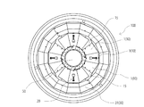
次に、可動式反射板10の動作について説明する。図4は、4つの可動式反射板10を広角位置にした状態のA−A断面図である。図5は、4つの可動式反射板10を狭角位置にした状態のA−A断面図である。図6は、4つの可動式反射板10を広角位置にした状態の底面図である。図7は、4つの可動式反射板10を狭角位置にした状態の底面図である。図8は、2つの可動式反射板10を広角位置にし、他の2つの可動式反射板10を狭角位置にした状態の底面図である。
Next, the operation of the
使用者が可動式反射板10に設けられた角度変更機構20の操作部14を左方向に回転させると、スリーブ11は調整バー12の末端方向に相対移動する。一方、第二ブラケット13は調整バー12の末端をそのまま支持している。従って、第二ブラケット13とスリーブ12との距離が接近し、それに伴って可動式反射板10は第一ブラケット52を中心とした上方への回転移動により光源ランプ50に対して引き上げられた状態(図5及び図7に示す状態であり、本明細書では「狭角位置」と規定する)となる。ちなみに、このときの第二ブラケット13は、図5に示すように、スリーブ11の側に若干引き寄せられて撓む。
When the user rotates the
使用者が可動式反射板10に設けられた角度変更機構20の操作部14を右方向に回転させると、スリーブ11は調整バー12の操作部14の方向に相対移動する。一方、第二ブラケット13は調整バー12の末端をそのまま支持している。従って、第二ブラケット13とスリーブ12との距離が離間し、それに伴って可動式反射板10は第一ブラケット52を中心とした下方への回転移動により光源ランプ50に対して引き下げられた状態(図4及び図6に示す状態であり、本明細書では「広角位置」と規定する)となる。ちなみに、このときの第二ブラケット13は、図4に示すように、スリーブ11から離れて撓みが解消される。
When the user rotates the
ここで、角度変更機構20の操作部14は、図1〜図7に示すように、可動式反射板10の反射面1の側(光源ランプ50が存在する側)に設けられている。このため、天井や壁等に照射器具を設置した後であっても、角度変更機構20の操作部14に手が届き易いものとなっている。その結果、照明器具(光源ランプ10)からの光の照射方向を容易に変更することができる。
Here, as shown in FIGS. 1 to 7, the
ところで、本実施形態の反射笠100によれば、従来のように光源ランプ50の光軸を中心として照射範囲を拡大・縮小することは勿論のこと、さらには、照射範囲を移動させたり、照射範囲を特定の方向に拡大・縮小したりすることも可能となる。このような特徴的な光照射が可能となるのは、本実施形態の反射笠100には、可動式反射板10が複数箇所(本実施形態では四箇所)備えられており、夫々の可動式反射板10が個別に角度変更可能に構成されているからである。
By the way, according to the
例えば、図8に示すように、2つの可動式反射板10を広角位置にし、他の2つの可動式反射板10を狭角位置にした状態とすることができる。この場合、光源ランプ50の反射光は、図8における平面視で、右下方向に偏ることになる。
For example, as shown in FIG. 8, the two
このように、本発明の反射笠100であれば、照明器具を設置した後も、容易に照射範囲を移動させたり、特定の方向に拡大・縮小したりすることが可能となる。その結果、照射対象が移動した場合でも、照射対象を確実に照らすことができる。
Thus, with the
固定式反射板30は、光源ランプ50の取付位置から見て、可動式反射板10の外側に設けられている。本実施形態では、合計三十二枚の台形の反射面31を、光源ランプ50を取り囲むように二段に亘って横方向に連接させ、環状の固定式反射板30が形成されている。このような構成により、固定式反射板30による既定の範囲の照射と、可動式反射板10による照射対象の状態に応じた任意の範囲の照射とを同時に行うことができる。
The fixed
また、本実施形態の反射笠100には、可動式反射板10の周囲に漏れた光を反射させる拡張反射部15が設けられている。このため、可動式反射板10の角度を変更したことによって可動式反射板10の周囲に隙間ができた場合でも、拡張反射部15により可動式反射板10の周囲に漏れた光を確実に反射させることができる。その結果、反射笠100の反射効率が向上する。
In addition, the
さらに、本実施形態の反射笠100では、光源ランプ50は、照明器具のベース51に固定されている。このような構造のため、光源ランプ50からの照射光を安定させることができる。その結果、可動式反射板10の操作をするだけで、照射強度、照射角度、及び照射範囲の細かい調整も容易に行うことができる。また、光源ランプ50が移動しないので、照明器具の配線を簡素化することができる。
Furthermore, in the
なお、本実施形態においては、反射笠100は、図1、図2、図4、及び図5に示されるように、光源ランプ50の取付位置から徐々に内径が拡大する釣鐘のような形状となっている。このため、反射笠100の真下では光源ランプ50の反射像(投影像)の変形量が少なく、必要な照射光の強度を確保できるが、反射笠100の真下から離れた位置では反射像(投影像)が引き伸ばされることになるため、照射光の強度が低下し易くなる。そこで、本実施形態では、可動式反射板10の反射面1、及び固定式反射板30の反射面31を、光源ランプ50を取り囲むように多段配置している。これにより、反射面1、及び反射面31で反射される光源ランプ50の反射像の数が多くなる。本実施形態の反射笠100では、反射面1、及び反射面31が合計44枚あるため、反射像の数も44となる。そうすると、反射光(投影光)のキメがより細かく且つムラが少なくなる。その結果、反射笠100の真下から離れた位置でも、比較的高品質な反射光(投影光)を得ることができる。また、本実施形態のように反射面1、及び反射面31の数が多くなると、高級感のあるデザイン性に優れた反射笠100を実現することもできる。なお、反射面1、及び反射面31の段数は、照明器具の大きさ、照射距離、照射範囲等の諸条件に応じて、適宜増加させることができる。また、本実施形態では、反射笠100を釣鐘のような形状としているが、例えば、中間部にくびれを設ける等して、外観に変化を持たせることも可能である。
In the present embodiment, the
反射笠100においては、照射対象を充分に照らしつつ、その周辺では眩しさを低減したいという要望もある。そこで、本実施形態の反射笠100においては、光源ランプ50の取付位置から見て外側に配置されている固定式反射板30は、それより内側に配置されている可動式反射板10より、光の拡散率が大きくなるように構成されている。例えば、固定式反射板30の光の拡散率を84%以上とし、可動式反射板10の光の拡散率を12%未満に設定する。これにより、光源ランプ50から照射される光のうち、可動式反射板10に当たる光は確実に照射方向へと反射されるとともに、固定式反射板30に当たる光は充分に拡散される。従って、照射対象物を充分な明るさで照らしつつ、当該照射対象物の周辺の人々が感じる眩しさを低減することができる。光の拡散率の調整は、組立前の金属板に対して、例えば、サンドブラストや化学研磨処理等の表面処理を施すことで、適切な値に設定することができる。
In the
次に、本発明の反射笠100を使用して行った具体的な実施例について説明する。
Next, the specific Example performed using the
実施例1では、上記実施形態で説明した44個の反射面を有する反射笠100を1台使用した。反射笠100に出力150Wの光源ランプ50を装着し、これを暗室内の所定位置(水平距離:0mm,垂直距離:0mm)に設置した。そして、可動式反射板10を、(1)狭角位置、(2)中間角度位置、(3)広角位置に設定し、照射光の照度を測定した。測定では、反射笠100からの水平距離が0〜2000mmの地点、及び反射笠100からの垂直距離が2000〜4000mmの地点において、照度計にて照度(単位:ルクス)を測定した。測定結果を図9の表に示す。
In Example 1, one reflecting
(1)狭角位置において、反射笠100の直下(水平距離:0mm,垂直距離:2000mm)では、3723ルクスの明るさが計測された。そして、反射笠100から離れるにつれて照度は徐々に低下し、反射笠100から垂直方向で最も離れた位置(水平距離:0mm,垂直距離:4000mm)で945ルクスとなり、水平方向で最も離れた位置(水平距離:2000mm,垂直距離:4000mm)で185ルクスとなった。
(1) At a narrow angle position, a brightness of 3723 lux was measured immediately below the reflecting shade 100 (horizontal distance: 0 mm, vertical distance: 2000 mm). The illuminance gradually decreases as the distance from the reflecting
(2)中間角度位置において、反射笠100の直下(水平距離:0mm,垂直距離:2000mm)では、3378ルクスの明るさが計測された。そして、反射笠100から離れるにつれて照度は徐々に低下し、反射笠100から垂直方向で最も離れた位置(水平距離:0mm,垂直距離:4000mm)で683ルクスとなり、水平方向で最も離れた位置(水平距離:2000mm,垂直距離:4000mm)で240ルクスとなった。
(2) At an intermediate angle position, a brightness of 3378 lux was measured immediately below the reflective shade 100 (horizontal distance: 0 mm, vertical distance: 2000 mm). Then, the illuminance gradually decreases as the distance from the reflecting
(3)広角位置において、反射笠100の直下(水平距離:0mm,垂直距離:2000mm)では、2669ルクスの明るさが計測された。そして、反射笠100から離れるにつれて照度は徐々に低下し、反射笠100から垂直方向で最も離れた位置(水平距離:0mm,垂直距離:4000mm)で558ルクスとなり、水平方向で最も離れた位置(水平距離:2000mm,垂直距離:4000mm)で255ルクスとなった。
(3) At a wide-angle position, a brightness of 2669 lux was measured immediately below the reflective shade 100 (horizontal distance: 0 mm, vertical distance: 2000 mm). The illuminance gradually decreases as the distance from the reflecting
上記(1)〜(3)の測定結果より、反射笠100の可動式反射板10を狭角位置から広角位置に移動させるに従って、光の照度が均等化されることが確認された。このように、本発明の反射笠100を使用すれば、可動式反射板10の角度を調整するだけの簡単な操作で、均等な光照射を容易に実現することが可能となる。
From the measurement results of (1) to (3) above, it was confirmed that the illuminance of light was equalized as the
実施例2では、上記実施形態で説明した44個の反射面を有する反射笠100を2台使用した。夫々の反射笠100に出力150Wの光源ランプ50を装着し、これらを可動式反射板10の角度に応じて2000mm〜4000mm離間させて暗室内に配置した。各反射笠100における可動式反射板10の角度は、実施例1と同様の角度である(1)狭角位置、(2)中間角度位置、(3)広角位置に設定し、照射光の照度を測定した。測定では、各反射笠100からの水平距離が500mm毎の地点、及び反射笠100からの垂直距離が2000〜4000mmの地点において、照度計にて照度(単位:ルクス)を測定した。測定結果を図10の表に示す。
In Example 2, two reflecting
(1)狭角位置において、反射笠100の直下(水平距離:0mm及び2000mm,垂直距離:2000mm)では、3817ルクスの明るさが計測された。そして、反射笠100から離れるにつれて照度は徐々に低下し、反射笠100から垂直方向で最も離れた位置(水平距離:0mm及び2000mm,垂直距離:4000mm)で1130ルクスとなり、水平方向で最も離れた位置(水平距離:1000mm,垂直距離:4000mm)で1148ルクスとなった。
(1) At a narrow angle position, a brightness of 3817 lux was measured immediately below the reflective shade 100 (horizontal distance: 0 mm and 2000 mm, vertical distance: 2000 mm). The illuminance gradually decreases as the distance from the reflecting
(2)中間角度位置において、反射笠100の直下(水平距離:0mm及び3500mm,垂直距離:2000mm)では、3378ルクスの明るさが計測された。そして、反射笠100から離れるにつれて照度は徐々に低下し、反射笠100から垂直方向で最も離れた位置(水平距離:0mm及び3500mm,垂直距離:4000mm)で683ルクスとなり、水平方向で最も離れた位置(水平距離:1500mm及び2000mm,垂直距離:4000mm)で628ルクスとなった。
(2) At an intermediate angle position, a brightness of 3378 lux was measured immediately below the reflective shade 100 (horizontal distance: 0 mm and 3500 mm, vertical distance: 2000 mm). The illuminance gradually decreases as the distance from the reflecting
(3)広角位置において、反射笠100の直下(水平距離:0mm及び4000mm,垂直距離:2000mm)では、2669ルクスの明るさが計測された。そして、反射笠100から離れるにつれて照度は徐々に低下し、反射笠100から垂直方向で最も離れた位置(水平距離:0mm及び4000mm,垂直距離:4000mm)で558ルクスとなり、水平方向で最も離れた位置(水平距離:2000mm,垂直距離:4000mm)で510ルクスとなった。
(3) At a wide-angle position, a brightness of 2669 lux was measured immediately below the reflective shade 100 (horizontal distance: 0 mm and 4000 mm, vertical distance: 2000 mm). The illuminance gradually decreases as the distance from the reflecting
上記(1)〜(3)の測定結果より、2台の反射笠100の可動式反射板10を狭角位置から広角位置に移動させるに従って、光の照度が均等化されることが確認された。さらに、1台の反射笠100を使用した場合より、2台の反射笠100を使用した方が、光の照度をより均等化することが可能となることが確認された。このように、本発明の反射笠100を使用すれば、可動式反射板10の角度を調整するだけの簡単な操作で、均等な光照射を容易に実現することが可能となる。
From the measurement results of (1) to (3) above, it was confirmed that the illuminance of light was equalized as the
本発明の反射笠は、ルームライト、ダウンライト、スポットライト、車両用ヘッドライト等の照明器具において好適に利用することができる。 The reflective shade of the present invention can be suitably used in lighting devices such as room lights, downlights, spotlights, and vehicle headlights.
1 反射面
10 可動式反射板
11 スリーブ
12 調整バー
13 第二ブラケット(ブラケット)
14 操作部
15 拡張反射部
20 角度変更機構
30 固定式反射板
50 光源ランプ
51 ベース
100 反射笠
DESCRIPTION OF
Claims (5)
前記光源ランプの光を反射させる反射面を有するとともに前記光源ランプを取り囲むように配置された複数の可動式反射板と、
前記光源ランプに対する前記複数の可動式反射板の夫々の角度を個別に変更する複数の角度変更機構と、を備え、
前記複数の可動式反射板の前記反射面の側に前記複数の角度変更機構の夫々の操作部が設けられ、
前記複数の角度変更機構の夫々が、前記可動式反射板に固定されたスリーブと、前記照明器具のベースにブラケットを介して基端側が支持されて前記スリーブに貫通螺合された調整バーと、前記調整バーの先端部に設けられた前記操作部とを備えて構成され、
前記操作部を回転させることで前記調整バーに螺合した前記スリーブが前記調整バーに対して相対移動して前記可動式反射板の角度が変更されるように構成されている反射笠。 A reflective shade that reflects the light of the light source lamp of the lighting fixture in the irradiation direction,
A plurality of movable reflectors having a reflecting surface for reflecting the light of the light source lamp and disposed so as to surround the light source lamp;
A plurality of angle changing mechanisms for individually changing the respective angles of the plurality of movable reflectors with respect to the light source lamp,
Operation of each of the plurality of angle changing mechanism is provided, et al is on the side of the reflecting surface of said plurality of movable reflector,
Each of the plurality of angle changing mechanisms includes a sleeve fixed to the movable reflector, an adjustment bar that is supported by a base end of the lighting fixture via a bracket and is threaded through the sleeve. The operation bar provided at the tip of the adjustment bar,
A reflection shade configured to rotate the operation portion so that the sleeve screwed to the adjustment bar moves relative to the adjustment bar to change the angle of the movable reflector.
前記光源ランプの光を反射させる反射面を有するとともに前記光源ランプを取り囲むように配置された複数の可動式反射板と、
前記光源ランプに対する前記複数の可動式反射板の夫々の角度を個別に変更する複数の角度変更機構と、を備え、
前記複数の可動式反射板の前記反射面の側に前記複数の角度変更機構の夫々の操作部が設けられ、
前記複数の可動式反射板の周囲に漏れた光を反射させる拡張反射部を備えている反射笠。 A reflective shade that reflects the light of the light source lamp of the lighting fixture in the irradiation direction,
A plurality of movable reflectors having a reflecting surface for reflecting the light of the light source lamp and disposed so as to surround the light source lamp;
A plurality of angle changing mechanisms for individually changing the respective angles of the plurality of movable reflectors with respect to the light source lamp,
Each of the plurality of angle changing mechanisms is provided on the reflective surface side of the plurality of movable reflectors,
Anti Ikasa that offer extended reflecting portion for reflecting light leaked around the plurality of movable reflector.
前記光源ランプの光を反射させる反射面を有するとともに前記光源ランプを取り囲むように配置された複数の可動式反射板と、
前記光源ランプに対する前記複数の可動式反射板の夫々の角度を個別に変更する複数の角度変更機構と、を備え、
前記複数の可動式反射板の前記反射面の側に前記複数の角度変更機構の夫々の操作部が設けられ、
前記光源ランプの取付位置から見て、前記複数の可動式反射板の外側に固定式反射板が設けられ、
前記固定式反射板は、前記可動式反射板より光の拡散率が大きくなるように構成されている反射笠。
A reflective shade that reflects the light of the light source lamp of the lighting fixture in the irradiation direction,
A plurality of movable reflectors having a reflecting surface for reflecting the light of the light source lamp and disposed so as to surround the light source lamp;
A plurality of angle changing mechanisms for individually changing the respective angles of the plurality of movable reflectors with respect to the light source lamp,
Each of the plurality of angle changing mechanisms is provided on the reflective surface side of the plurality of movable reflectors,
Seen from the mounting position of the light source lamp, a fixed reflector is provided outside the plurality of movable reflectors,
The fixed reflector, anti Ikasa that is organized as diffusivity of light from the movable reflector is increased.
Priority Applications (1)
| Application Number | Priority Date | Filing Date | Title |
|---|---|---|---|
| JP2009123295A JP5144590B2 (en) | 2009-05-21 | 2009-05-21 | Reflex shade |
Applications Claiming Priority (1)
| Application Number | Priority Date | Filing Date | Title |
|---|---|---|---|
| JP2009123295A JP5144590B2 (en) | 2009-05-21 | 2009-05-21 | Reflex shade |
Publications (3)
| Publication Number | Publication Date |
|---|---|
| JP2010272358A JP2010272358A (en) | 2010-12-02 |
| JP2010272358A5 JP2010272358A5 (en) | 2012-06-07 |
| JP5144590B2 true JP5144590B2 (en) | 2013-02-13 |
Family
ID=43420221
Family Applications (1)
| Application Number | Title | Priority Date | Filing Date |
|---|---|---|---|
| JP2009123295A Expired - Fee Related JP5144590B2 (en) | 2009-05-21 | 2009-05-21 | Reflex shade |
Country Status (1)
| Country | Link |
|---|---|
| JP (1) | JP5144590B2 (en) |
Families Citing this family (9)
| Publication number | Priority date | Publication date | Assignee | Title |
|---|---|---|---|---|
| CN103162109B (en) * | 2011-12-14 | 2015-11-18 | 海洋王照明科技股份有限公司 | A kind of light fixture of adjustable light beam width |
| WO2015099205A1 (en) | 2013-12-23 | 2015-07-02 | 엘지전자 주식회사 | Robot cleaner |
| KR101693827B1 (en) * | 2016-04-11 | 2017-01-17 | 주식회사 글로벌고베 | Led lighting device having high efficiency radiating structure |
| CN106439553A (en) * | 2016-09-28 | 2017-02-22 | 合肥海宝节能科技有限公司 | Energy-saving lamp |
| CN106439555A (en) * | 2016-09-28 | 2017-02-22 | 合肥海宝节能科技有限公司 | Manufacturing method of reflecting cover for energy saving lamp |
| CN106439554A (en) * | 2016-09-28 | 2017-02-22 | 合肥海宝节能科技有限公司 | Reflecting cover of energy saving lamp |
| JP6996194B2 (en) | 2017-09-27 | 2022-01-17 | 東芝ライテック株式会社 | Lighting equipment |
| CN107957054A (en) * | 2017-12-06 | 2018-04-24 | 昆山恩都照明有限公司 | Lamps and lanterns reflecting plate |
| CN109556092A (en) * | 2018-12-19 | 2019-04-02 | 安徽八爪智能科技有限公司 | A kind of Multifunctional bedside lamp employing of angle adjustable |
Family Cites Families (4)
| Publication number | Priority date | Publication date | Assignee | Title |
|---|---|---|---|---|
| JPS57106109U (en) * | 1980-12-22 | 1982-06-30 | ||
| JPH0724161B2 (en) * | 1992-05-15 | 1995-03-15 | ヤマギワ株式会社 | Movable reflector of lighting equipment |
| JPH0668206U (en) * | 1993-02-25 | 1994-09-22 | 株式会社スプリング | Lighting angle adjustment device for lighting equipment |
| JP2008125412A (en) * | 2006-11-20 | 2008-06-05 | Matsushita Electric Works Ltd | Lighting fixture for supplementing plant with light |
-
2009
- 2009-05-21 JP JP2009123295A patent/JP5144590B2/en not_active Expired - Fee Related
Also Published As
| Publication number | Publication date |
|---|---|
| JP2010272358A (en) | 2010-12-02 |
Similar Documents
| Publication | Publication Date | Title |
|---|---|---|
| JP5144590B2 (en) | Reflex shade | |
| JP2010272358A5 (en) | ||
| US6152583A (en) | Adjustable luminaire having pivotable lamp and reflector assembly | |
| JP4845404B2 (en) | Lighting method and apparatus using reflector | |
| CN201764297U (en) | Operating lamp and illuminating units thereof | |
| KR100992555B1 (en) | Adjuster of irradiation angle for lighting fixtures | |
| JP5271600B2 (en) | Lighting device | |
| KR20090104589A (en) | Radiation angle control type spot-lamp | |
| KR20100124063A (en) | Lighting lens and light lamp with the same | |
| JP5756913B2 (en) | lighting equipment | |
| JP2003281910A (en) | Luminaire | |
| JP3216147U (en) | Outdoor light with a choice of light irradiation direction | |
| KR200379464Y1 (en) | Floodlight for ilumination with focus regulating system | |
| CN208381832U (en) | A kind of dual-purpose lighting lamp | |
| JP2007317462A (en) | Security luminaire | |
| CN213272210U (en) | Light refractor for air film building and air film building | |
| JP2010123538A (en) | Luminaire | |
| CN213333950U (en) | Projection lamp | |
| JP2004171963A (en) | Lighting apparatus | |
| JP4381469B1 (en) | Reflex shade | |
| JP5129639B2 (en) | lighting equipment | |
| JP2011009059A (en) | Lighting device | |
| JP2005346968A (en) | Lighting fixture | |
| KR101824152B1 (en) | The illumination device having the horizontal and vertical rotation function | |
| KR200309313Y1 (en) | device of indirect lighting combined with spotlight used a bamboo |
Legal Events
| Date | Code | Title | Description |
|---|---|---|---|
| A521 | Written amendment |
Free format text: JAPANESE INTERMEDIATE CODE: A523 Effective date: 20120423 |
|
| A621 | Written request for application examination |
Free format text: JAPANESE INTERMEDIATE CODE: A621 Effective date: 20120423 |
|
| A871 | Explanation of circumstances concerning accelerated examination |
Free format text: JAPANESE INTERMEDIATE CODE: A871 Effective date: 20120423 |
|
| A975 | Report on accelerated examination |
Free format text: JAPANESE INTERMEDIATE CODE: A971005 Effective date: 20120510 |
|
| A131 | Notification of reasons for refusal |
Free format text: JAPANESE INTERMEDIATE CODE: A131 Effective date: 20120807 |
|
| A521 | Written amendment |
Free format text: JAPANESE INTERMEDIATE CODE: A523 Effective date: 20120828 |
|
| TRDD | Decision of grant or rejection written | ||
| A01 | Written decision to grant a patent or to grant a registration (utility model) |
Free format text: JAPANESE INTERMEDIATE CODE: A01 Effective date: 20121113 |
|
| A01 | Written decision to grant a patent or to grant a registration (utility model) |
Free format text: JAPANESE INTERMEDIATE CODE: A01 |
|
| A61 | First payment of annual fees (during grant procedure) |
Free format text: JAPANESE INTERMEDIATE CODE: A61 Effective date: 20121122 |
|
| FPAY | Renewal fee payment (event date is renewal date of database) |
Free format text: PAYMENT UNTIL: 20151130 Year of fee payment: 3 |
|
| R150 | Certificate of patent or registration of utility model |
Ref document number: 5144590 Country of ref document: JP Free format text: JAPANESE INTERMEDIATE CODE: R150 Free format text: JAPANESE INTERMEDIATE CODE: R150 |
|
| R250 | Receipt of annual fees |
Free format text: JAPANESE INTERMEDIATE CODE: R250 |
|
| R250 | Receipt of annual fees |
Free format text: JAPANESE INTERMEDIATE CODE: R250 |
|
| R250 | Receipt of annual fees |
Free format text: JAPANESE INTERMEDIATE CODE: R250 |
|
| R250 | Receipt of annual fees |
Free format text: JAPANESE INTERMEDIATE CODE: R250 |
|
| LAPS | Cancellation because of no payment of annual fees |