JP5137892B2 - Solar cell unit - Google Patents
Solar cell unit Download PDFInfo
- Publication number
- JP5137892B2 JP5137892B2 JP2009097216A JP2009097216A JP5137892B2 JP 5137892 B2 JP5137892 B2 JP 5137892B2 JP 2009097216 A JP2009097216 A JP 2009097216A JP 2009097216 A JP2009097216 A JP 2009097216A JP 5137892 B2 JP5137892 B2 JP 5137892B2
- Authority
- JP
- Japan
- Prior art keywords
- solar cell
- frame member
- cell module
- fitting portion
- surface portion
- Prior art date
- Legal status (The legal status is an assumption and is not a legal conclusion. Google has not performed a legal analysis and makes no representation as to the accuracy of the status listed.)
- Expired - Fee Related
Links
Images


Classifications
-
- F—MECHANICAL ENGINEERING; LIGHTING; HEATING; WEAPONS; BLASTING
- F24—HEATING; RANGES; VENTILATING
- F24S—SOLAR HEAT COLLECTORS; SOLAR HEAT SYSTEMS
- F24S40/00—Safety or protection arrangements of solar heat collectors; Preventing malfunction of solar heat collectors
- F24S40/40—Preventing corrosion; Protecting against dirt or contamination
- F24S40/44—Draining rainwater or condensation
-
- F—MECHANICAL ENGINEERING; LIGHTING; HEATING; WEAPONS; BLASTING
- F24—HEATING; RANGES; VENTILATING
- F24S—SOLAR HEAT COLLECTORS; SOLAR HEAT SYSTEMS
- F24S25/00—Arrangement of stationary mountings or supports for solar heat collector modules
- F24S25/20—Peripheral frames for modules
-
- F—MECHANICAL ENGINEERING; LIGHTING; HEATING; WEAPONS; BLASTING
- F24—HEATING; RANGES; VENTILATING
- F24S—SOLAR HEAT COLLECTORS; SOLAR HEAT SYSTEMS
- F24S25/00—Arrangement of stationary mountings or supports for solar heat collector modules
- F24S25/60—Fixation means, e.g. fasteners, specially adapted for supporting solar heat collector modules
- F24S25/67—Fixation means, e.g. fasteners, specially adapted for supporting solar heat collector modules for coupling adjacent modules or their peripheral frames
-
- F—MECHANICAL ENGINEERING; LIGHTING; HEATING; WEAPONS; BLASTING
- F24—HEATING; RANGES; VENTILATING
- F24S—SOLAR HEAT COLLECTORS; SOLAR HEAT SYSTEMS
- F24S20/00—Solar heat collectors specially adapted for particular uses or environments
- F24S2020/10—Solar modules layout; Modular arrangements
- F24S2020/12—Coplanar arrangements with frame overlapping portions
-
- F—MECHANICAL ENGINEERING; LIGHTING; HEATING; WEAPONS; BLASTING
- F24—HEATING; RANGES; VENTILATING
- F24S—SOLAR HEAT COLLECTORS; SOLAR HEAT SYSTEMS
- F24S25/00—Arrangement of stationary mountings or supports for solar heat collector modules
- F24S2025/01—Special support components; Methods of use
- F24S2025/022—Sealing means between support elements, e.g. overlapping arrangements; Gap closing arrangements
-
- Y—GENERAL TAGGING OF NEW TECHNOLOGICAL DEVELOPMENTS; GENERAL TAGGING OF CROSS-SECTIONAL TECHNOLOGIES SPANNING OVER SEVERAL SECTIONS OF THE IPC; TECHNICAL SUBJECTS COVERED BY FORMER USPC CROSS-REFERENCE ART COLLECTIONS [XRACs] AND DIGESTS
- Y02—TECHNOLOGIES OR APPLICATIONS FOR MITIGATION OR ADAPTATION AGAINST CLIMATE CHANGE
- Y02B—CLIMATE CHANGE MITIGATION TECHNOLOGIES RELATED TO BUILDINGS, e.g. HOUSING, HOUSE APPLIANCES OR RELATED END-USER APPLICATIONS
- Y02B10/00—Integration of renewable energy sources in buildings
- Y02B10/10—Photovoltaic [PV]
-
- Y—GENERAL TAGGING OF NEW TECHNOLOGICAL DEVELOPMENTS; GENERAL TAGGING OF CROSS-SECTIONAL TECHNOLOGIES SPANNING OVER SEVERAL SECTIONS OF THE IPC; TECHNICAL SUBJECTS COVERED BY FORMER USPC CROSS-REFERENCE ART COLLECTIONS [XRACs] AND DIGESTS
- Y02—TECHNOLOGIES OR APPLICATIONS FOR MITIGATION OR ADAPTATION AGAINST CLIMATE CHANGE
- Y02E—REDUCTION OF GREENHOUSE GAS [GHG] EMISSIONS, RELATED TO ENERGY GENERATION, TRANSMISSION OR DISTRIBUTION
- Y02E10/00—Energy generation through renewable energy sources
- Y02E10/40—Solar thermal energy, e.g. solar towers
- Y02E10/47—Mountings or tracking
Description
本発明は、光、例えば太陽光を電力に直接変換する太陽電池モジュールを複数備えて屋根材の代わりに構成される建材一体型の太陽電池ユニットに関し、特に、隣り合う太陽電池モジュールの繋ぎ目における防水に関するものである。 The present invention relates to a building material-integrated solar cell unit that includes a plurality of solar cell modules that directly convert light, for example, sunlight into electric power, and is configured instead of a roofing material, and in particular, at a joint between adjacent solar cell modules. It is about waterproofing.
近年、地球温暖化防止対策の有力な切り札として太陽光発電システムが注目されている。この太陽光発電システムは、太陽電池パネルとその付属部品から構成される太陽電池モジュールにより構築されるシステムである。作今、電力会社が一般の需要家からの余剰電力の購入をすることもあり、各家庭や事業所内の分散型電源システムとして、その需要も急速に伸びている。特に西欧諸国では、温暖化防止対策の最有力な電源システムとして、太陽電池モジュールの需要は多く見込まれており、我が国からの輸出も増えている。 In recent years, a photovoltaic power generation system has attracted attention as a powerful trump card for preventing global warming. This solar power generation system is a system constructed by a solar cell module composed of a solar cell panel and its accessory parts. Nowadays, electric power companies sometimes purchase surplus power from general consumers, and the demand is growing rapidly as a distributed power supply system in each home and office. In particular, in Western Europe, demand for solar cell modules is expected as a leading power system for preventing global warming, and exports from Japan are also increasing.
また、太陽電池モジュールを家屋の屋根等の傾斜面に沿って上下左右に複数配置して、屋根材の代わりに構成される建材一体型の太陽電池ユニットが普及している。この太陽電池ユニットでは、家屋の野地面に雨水が浸入することを防止するために隣り合う太陽電池モジュールの繋ぎ目の防水が重要となっている。 In addition, a building material-integrated solar cell unit configured by replacing a roof material with a plurality of solar cell modules arranged vertically and horizontally along an inclined surface such as a roof of a house has become widespread. In this solar cell unit, waterproofing of joints between adjacent solar cell modules is important in order to prevent rainwater from entering the field of the house.
この種の太陽電池ユニットにおける隣り合う太陽電池モジュールの繋ぎ目の防水技術としては、例えば、特許文献1に記載されているようなものがある。この特許文献1に記載された技術は、傾斜方向に沿って隣り合う2つの太陽電池モジュールの下枠材の天井板と上枠材の突起板によって雨水溜まりを形成することで、2つの太陽電池モジュールの繋ぎ目に侵入する水を防いでいる。
As a technique for waterproofing joints between adjacent solar cell modules in this type of solar cell unit, for example, there is one described in
しかしながら、従来の特許文献1に記載された技術は、下枠材における太陽電池パネルと嵌合する第1の嵌合部と上枠材における太陽電池パネルと嵌合する第2の嵌合部の間に雨水溜まりが形成されている。そのため、傾斜方向に沿って隣り合う2つの太陽電池モジュールにおける太陽電池パネルの間隔が長くなり、太陽電池ユニットが大型化し、設置に必要な面積が拡大する、という問題があった。
However, the technique described in the
本発明の目的は、上記の問題点を考慮し、隣り合う2つの太陽電池モジュールの繋ぎ目に水の侵入を防止できると共に設置に必要な面積を縮小することができる太陽電池ユニットを提供することにある。 In view of the above problems, an object of the present invention is to provide a solar cell unit capable of preventing water from entering the joint between two adjacent solar cell modules and reducing the area required for installation. It is in.
上記課題を解決し、本発明の目的を達成するため、本発明の太陽電池ユニットは、水平に対して傾斜した載置面に沿ってその傾斜方向及び該傾斜方向と直交する横方向に配置された複数の太陽電池モジュールと、から構成されている。
複数の太陽電池モジュールは、複数の太陽電池セルを有すると共に四角形の平板状に形成された太陽電池パネルと、第1の枠材と、第2の枠材とを備えている。第1の枠材は、太陽電池パネルの四辺のうち載置面に配置した際に傾斜方向の上側に位置する上辺と嵌合する第1の嵌合部と、第1の嵌合部の上面から突出する突起部とから構成されている。そして、第2の枠材は、太陽電池パネルの上辺と対向する下辺と嵌合する第2の嵌合部と、第2の嵌合部から載置面に近づく方向に傾斜して形成されたカバー部と、から構成されている。そして、このカバー部は、傾斜方向の下側に配置される太陽電池モジュールの第1の枠材の突起部を覆うことで第1の嵌合部の上面との間に第1の通水路を形成する。
また、太陽電池モジュールは、太陽電池パネルの四辺のうち上辺及び下辺と略垂直をなす側辺と嵌合する第3の嵌合部からなる第3の枠材を有する。太陽電池モジュールは、横方向に隣り合う2つの太陽電池モジュールの第3の枠材との間に嵌め込まれる弾性を有する止水部材を備える。
止水部材は、横方向に隣り合う2つの太陽電池モジュールの第3の枠材の間に第2の通水路を形成して嵌め込まれる。そして、止水部材を嵌め込んだ際に、第1の通水路から流れた水が第2の通水路に流れる。
In order to solve the above-mentioned problems and achieve the object of the present invention, the solar cell unit of the present invention is disposed in the tilt direction along the mounting surface tilted with respect to the horizontal and in the lateral direction perpendicular to the tilt direction. And a plurality of solar cell modules.
The plurality of solar cell modules includes a solar cell panel having a plurality of solar cells and formed in a rectangular flat plate shape, a first frame member, and a second frame member. The first frame member includes a first fitting portion that fits with an upper side that is located on the upper side in the inclination direction when the first frame member is arranged on the mounting surface among the four sides of the solar cell panel, and an upper surface of the first fitting portion. And a projecting portion protruding from the head. And the 2nd frame material was formed inclining in the direction which approaches a mounting surface from the 2nd fitting part and the 2nd fitting part fitted to the lower side opposite to the upper side of a solar cell panel. And a cover part. And this cover part covers the projection part of the 1st frame material of the solar cell module arrange | positioned on the lower side of an inclination direction, and makes a 1st water flow path between the upper surfaces of a 1st fitting part. Form.
In addition, the solar cell module includes a third frame member that includes a third fitting portion that is fitted to a side that is substantially perpendicular to the upper side and the lower side of the four sides of the solar cell panel. A solar cell module is provided with the water stop member which has the elasticity fitted between the 3rd frame material of two solar cell modules adjacent to a horizontal direction.
The water stop member is fitted in a second water passage between the third frame members of the two solar cell modules adjacent in the lateral direction. Then, when the water stop member is fitted, the water that has flowed from the first water passage flows into the second water passage.
本発明の太陽電池ユニットによれば、第1の枠材に設けた突起部と第2の枠材に設けたカバー部によって、傾斜方向に沿って隣り合う2つの太陽電池モジュールの繋ぎ目に侵入する水を防ぐことができる。更に、第1の枠材の第1の嵌合部の上面部に第1の通水路を形成しているため、傾斜方向に沿って隣り合う2つの太陽電池モジュールの太陽電池パネルの距離を縮めることができる。その結果、太陽電池ユニットを小型化することができ、設置スペースを縮小することができる。 According to the solar cell unit of the present invention, the protrusions provided on the first frame member and the cover portions provided on the second frame member enter the joint between two solar cell modules adjacent along the inclination direction. Can prevent water to run. Furthermore, since the 1st water flow path is formed in the upper surface part of the 1st fitting part of a 1st frame material, the distance of the solar cell panel of two solar cell modules adjacent along an inclination direction is shortened. be able to. As a result, the solar cell unit can be reduced in size, and the installation space can be reduced.
以下、本発明の太陽電池ユニットの実施の形態例について、図1〜図10を参照して説明する。なお、各図において共通の部材には、同一の符号を付している。また、本発明は、以下の形態に限定されるものではない。
また、説明は以下の順序で行う。
1.太陽電池ユニットの構成例
1−1.太陽電池モジュール
1−2.アース棒
1−3.ゴムガスケット
2.太陽電池ユニットの組み立て
Hereinafter, embodiments of the solar cell unit of the present invention will be described with reference to FIGS. In addition, the same code | symbol is attached | subjected to the common member in each figure. The present invention is not limited to the following form.
The description will be given in the following order.
1. Configuration example of solar cell unit 1-1. Solar cell module 1-2. Earth stick 1-3. Rubber gasket2. Assembling the solar cell unit
1.太陽電池ユニットの構成例
本発明の実施の形態例(以下、「本例」という。)に係る太陽電池ユニット10は、屋根材と一体型の太陽電池ユニットである。
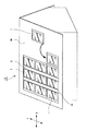
図1は、本例の太陽電池ユニットを示す模式図、図2は、本例の太陽電池ユニットの平面図である。
1. Configuration Example of Solar Cell Unit A
FIG. 1 is a schematic view showing the solar cell unit of this example, and FIG. 2 is a plan view of the solar cell unit of this example.
図1及び図2に示すように、太陽電池ユニット10は、複数の太陽電池モジュール1と、止水部材の一具体例を示すゴムガスケット2とから構成されている。複数の太陽電池モジュール1は、載置面の一具体例を示す屋根の野地板Mに沿ってその傾斜方向Yと、傾斜方向Yと直交する横方向Xに並べて配設されている。そして、横方向Xに並べられた太陽電池モジュール1の間を埋めるようにゴムガスケット2が嵌め込まれている。
As shown in FIG.1 and FIG.2, the
1−1.太陽電池モジュール
次に、図2〜図6を参照して太陽電池ユニットに係る太陽電池モジュールについて説明する。
図3は本例の太陽電池ユニットを示す分解斜視図、図4及び図5は、太陽電池ユニットの断面図、図6は、本例の太陽電池ユニットの要部を拡大して示す平面図である。
図3に示すように、太陽電池モジュール1は、平板状の太陽電池パネル3と、この太陽電池パネル3の周囲を囲む枠材6とを有している。
1-1. Next, the solar cell module according to the solar cell unit will be described with reference to FIGS.
3 is an exploded perspective view showing the solar cell unit of this example, FIGS. 4 and 5 are sectional views of the solar cell unit, and FIG. 6 is a plan view showing an enlarged main part of the solar cell unit of this example. is there.
As shown in FIG. 3, the
[太陽電池パネル]
太陽電池パネル3は、略四角形をなす平板状に形成されている。この太陽電池パネル3は、野地板Mに載置した際に、傾斜方向Yの上側である一側に位置する上辺3aと、この上辺3aと対向する下辺3bと、上辺3a及び下辺3bと略垂直をなす2つの側辺3c,3cを有している。そして、この太陽電池パネル3は、四角形に形成された複数の太陽電池セル5を、平板状に形成された裏面保護部材と透過ガラス等の表面保護部材との間に封止材により封止して構成されている。
[Solar panel]
The
この太陽電池パネル3の長手方向及び短手方向には、複数の太陽電池セル5が受光面を同一方向に向けて並べて配設されている。本例では、54枚の太陽電池セル5が設けられている。そして、この54枚の太陽電池セル5は、不図示の配線を介して全て直列に接続されている。
In the longitudinal direction and the short direction of the
本例では、太陽電池セル5として、結晶系の太陽電池セルが用いられている。しかしながら、本例に用いられる太陽電池セル5としては、結晶系の太陽電池セルに限定されるものではなく、非晶質系の太陽電池セルや結晶系と非晶質系の混合タイプの太陽電池セルを用いてもよい。なお、太陽電池セル群を構成する太陽電池セル5の数は、上述した54枚に限定されるものではなく、53枚以下または55枚以上設けるようにしてもよい。更に、太陽電池セル5は、必ずしも四角形状にする必要はなく、略五角形状や円形状に形成してもよい。 In this example, a crystalline solar battery cell is used as the solar battery cell 5. However, the solar battery cell 5 used in this example is not limited to a crystalline solar battery cell, and is not limited to an amorphous solar battery cell or a mixed crystal / amorphous solar battery. A cell may be used. In addition, the number of the photovoltaic cells 5 which comprise a photovoltaic cell group is not limited to 54 sheets mentioned above, You may make it provide 53 sheets or less or 55 sheets or more. Furthermore, the solar battery cell 5 does not necessarily have to be a square shape, and may be formed in a substantially pentagonal shape or a circular shape.
また、図5に示すように、太陽電池パネル3の背面には、端子ボックス4が設けられている(図5参照)。端子ボックス4には、バイパスダイオードが内蔵されている。そして、このバイパスダイオードは、配線を介して複数の太陽電池セル5と電気的に接続されている。また、この端子ボックス4からは、出力用の2つの配線ケーブル31,32が引き出されている。そして、第1の配線ケーブル31の先端には、正極端子33が設けられており、第2の配線ケーブル32の先端には、負極端子34が設けられている。
Moreover, as shown in FIG. 5, the terminal box 4 is provided in the back surface of the solar cell panel 3 (refer FIG. 5). The terminal box 4 contains a bypass diode. And this bypass diode is electrically connected with the several photovoltaic cell 5 via wiring. Further, two
[枠材]
再び図3に戻って説明すると、枠材6は、太陽電池パネル3の上辺3a,下辺3b及び2つの側辺3c,3cに取り付けられている。この枠材6は、第1の枠材7と、第2の枠材8と、2つの第3の枠材9,9とから構成されている。第1の枠材7、第2の枠材8及び第3の枠材9の材質としては、例えば、アルミニウム合金が好適であるが、その他の金属を用いることもでき、または樹脂や木材等を用いてもよい。
[Frame material]
Referring back to FIG. 3 again, the
[第1の枠材]
第1の枠材7は、太陽電池パネル3の上辺3aに取り付けられている。図4に示すように、この第1の枠材7は、太陽電池パネル3の上辺3aに嵌合する第1の嵌合部11と、突起部12と、第1のフランジ部13とから構成されている。
[First frame material]
The
第1の嵌合部11は、断面形状がコの字状に形成されており、上面部11aと、この上面部11aと対向する底面部11bと、上面部11aと底面部11bを接続する接続面部11cとを有している。接続面部11cは、上面部11aと底面部11bにおける傾斜方向Yの一端側に配設されている。そして、この第1の嵌合部11は、上面部11aと底面部11bにおける傾斜方向Yの他端側が開口している。この第1の嵌合部11の開口側から、太陽電池パネル3の上辺3aが端面封止材14を介して挿入されている。このとき、上面部11aは、太陽電池パネル3の正面側である受光面側に位置し、底面部11bは、太陽電池パネル3の裏側に位置している。
The first
また、上面部11aにおける端面封止材14と接触する面と反対側の面である上面には、突起部12が設けられている。突起部12は、上面部11aの上面における傾斜方向Yの一端側、すなわち接続面部11c側に形成されており、上面部11aの長手方向の略全体に亘って延在している。そして、この突起部12は、上面部11aから野地板Mに対して離れる方向に突出している。なお、本例では、突起部12は、断面形状が略四角形状に形成されているが、これに限定されるものではなく、断面形状を略三角形状に形成してもよい。
Further, the
また、第1の嵌合部11における底面部11bには、第1のフランジ部13が設けられている。第1のフランジ部13は、底面部11bにおける端面封止材14と接触する面と反対側の面である底面から野地板Mに近づく方向に突出している。この第1のフランジ部13は、底面部11bの底面における傾斜方向Yの一端側、すなわち接続面部11c側に形成されており、底面部11bの長手方向の略全体に亘って延在している。
A
[第2の枠材]
第2の枠材8は、太陽電池パネル3の下辺3bに取り付けられている。図4に示すように、この第2の枠材8は、太陽電池パネル3の下辺3bに嵌合する第2の嵌合部16と、カバー部17と、第2のフランジ部18とから構成されている。
[Second frame material]
The
第2の嵌合部16は、断面形状がコの字状に形成されており、上面部16aと、この上面部16aと対向する底面部16bと、上面部16aと底面部16bを接続する接続面部16cとを有している。接続面部16cは、上面部16aと底面部16bにおける傾斜方向Yの他端側に配設されている。そして、この第2の嵌合部16は、上面部16aと底面部16bにおける傾斜方向Yの一端側が開口している。この第2の嵌合部16の開口側から、太陽電池パネル3の下辺3bが端面封止材14を介して挿入されている。このとき、上面部16aは、太陽電池パネル3の正面側である受光面側に位置し、底面部16bは、太陽電池パネル3の裏側に位置している。
The second
また、上面部16aにおける端面封止材14と接触する面と反対側の面である上面は、円弧状に形成されており、傾斜方向Yの他端側から一端側にかけて太陽電池パネル3に近づく方向に傾斜している。そして、この上面部16aには、カバー部17が連続して形成されている。なお、上面を円弧状に形成した例を説明したが、これに限定されるものではなく、直線状や傾斜させて形成してもよい。
Moreover, the upper surface which is a surface on the opposite side to the surface which contacts the end
カバー部17は、上面部16aから傾斜方向Yの他側に向けて突出し、且つ野地板Mに近づく方向に傾斜している。図3及び図6に示すように、このカバー部17の長手方向の両端には、切り欠き17aが形成されている。また、図4に示すように、このカバー部17は、傾斜方向Yの他側、すなわち下側に配置される太陽電池モジュール1における第1の枠材7と突起部12を覆う。突起部12を覆った際に、カバー部17の先端は、第1の枠材7における第1の嵌合部11の上面部11aに当接する。これにより、傾斜方向Yの下側から吹き上がる水が、第1の枠材7と第2の枠材8の間に侵入することを防ぐができる。なお、防水効果を高めるために、カバー部17の先端を上面部11aに締まる角度に設定し、上面部11aにカバー部17を押し付けるように接触させてもよい。
The
また、本例では、第1の枠材7における第1の嵌合部11の上面部11aに、カバー部17の先端が当接するように構成した例を説明したが、これに限定されるものではない。第1の嵌合部11の上面部11aにカバー部17の先端以外の箇所が当接してもその目的を達成できるものである。
Further, in this example, the example in which the tip of the
また、カバー部17で突起部12を覆った際に、カバー部17と上面部11aとの間に第1の通水路21が形成される。図6に示すように、この第1の通水路21は、横方向Xに沿って延在している。この通水路21は、第1の枠材7の上面部11aとカバー部17の間に侵入した水Wを横方向Xに排水させるためのものである。そして、第1の通水路21を流れる水Wは、カバー部17の両端に設けた切り欠き17aから太陽電池パネル3側へ排水されて、傾斜方向Yの他側に排水される。
Moreover, when the
なお、第1の通水路21の両端に切り欠き17aを設けない場合、第1の通水路21に水Wが溜まり、凍結するおそれがある。そして、水Wが凍結すると体積が膨張し、第1の枠材7及び第2の枠材8を変形させる。その結果、水Wが溶けた後も第1の枠材7及び第2の枠材8に歪みが生じ、防水性能が低下するおそれがある。しかしながら、本例では、カバー部17の両端に切り欠き17aを設けて、第1の通水路21を流れる水Wを太陽電池パネル3側に排水させることで、水Wが第1の通水路21に溜まることを防止できる。
溜まった水Wが凍結して、第1の枠材7及び第2の枠材8を変形させることを防止することが可能である。
In addition, when
It is possible to prevent the accumulated water W from freezing and deforming the
更に、第1の枠材7に設けた突起部12によって、第1の通水路21に侵入した水Wが第1の枠材7の第1の嵌合部11と第2の枠材8の第2の嵌合部16の間に侵入することを防止することができる。
Further, the water W that has entered the
このように、傾斜方向Yに沿って並べられた2つの太陽電池モジュール1A,1Bの繋ぎ目の排水構造は、傾斜方向Yの下側に配設された第1の太陽電池モジュール1Aの第1の嵌合部11の上面部11a上に位置している。そのため、図4に示すように、第1の太陽電池モジュール1Aにおける第1の嵌合部11の背面と、傾斜方向Yの上側に配設される第2の太陽電池モジュール1Bにおける第2の嵌合部16の背面とを当接させることができる。その結果、第1の太陽電池モジュール1Aの太陽電池パネル3と、第2の太陽電池モジュール1Bの太陽電池パネル3における傾斜方向Yの間隔を小さくすることができ、太陽電池ユニット10の小型化を図ることができる。これにより、太陽電池ユニット10の設置に必要なスペースを縮小することを可能としている。
Thus, the joint drainage structure of the two
第2のフランジ部18は、第2の嵌合部16における底面部16bに設けられている。第2のフランジ部18は、底面部16bにおける端面封止材14と接触する面と反対側の面である底面から野地板Mに近づく方向に突出している。この第2のフランジ部18は、底面部16bの底面における接続面部16c側に形成されており、底面部16bの長手方向の略全体に亘って延在している。
The
[第3の枠材]
図2及び図3に示すように、第3の枠材9は、太陽電池パネル3の四辺のうち上辺3a及び下辺3bと略垂直をなす側辺3cに取り付けられている。図5に示すように、この第3の枠材9は、側辺3cと嵌合する第3の嵌合部22と、突出部23と、脚部24と、脚部24と第3の嵌合部22を接続する接続部26から構成されている。
[Third frame material]
As shown in FIGS. 2 and 3, the
第3の嵌合部22は、第1の嵌合部11及び第2の嵌合部16と同様に、断面形状がコの字状に形成されている。この第3の嵌合部22は、上面部22aと、この上面部22aと対向する底面部22bと、上面部22aと底面部22bを接続する接続面部22cとを有している。
The third
太陽電池パネル3における横方向Xの一側の側辺3cに嵌合する第3の嵌合部22の接続面部22cは、上面部22aと底面部22bにおける横方向Xの一端側に配設されている。これに対し、太陽電池パネル3における横方向Xの他側の側辺3cに嵌合する第3の嵌合部22の接続面部22cは、上面部22aと底面部22bにおける横方向Xの他端側に配設されている。そして、この上面部22a、底面部22b及び接続面部22cで形成された凹部に、太陽電池パネル3の側辺3cが端面封止材14を介して挿入されている。
The
図6に示すように、上面部22aの長手方向の一端側、すなわち傾斜方向Yの一端側には、切り欠き25が形成されている。また、上面部22aには、略平板状の突出部23が連続して形成されている。
As shown in FIG. 6, a
突出部23は、上面部22aから太陽電池パネル3と離れる方向に突出している。この突出部23は、突出片23aと、傾斜片23bとから構成されている。突出片23aは、上面部22aから野地板Mに対して離れる方向に傾斜している。傾斜片23bは、突出片23aから連続し、且つ突出片23aから野地板Mに近づく方向に傾斜している。
The protruding
図3及び図6に示すように、接続部26は、第3の嵌合部22の底面部22bから野地板Mに向けて突出して設けられている。この接続部26には、端子ボックス4から引き出された第1の配線ケーブル31及び第2の配線ケーブル32が貫通する貫通孔27aが設けられている。
As shown in FIGS. 3 and 6, the
図7A及び図7Bを参照して、第3の枠材9に設けた貫通孔27aについて説明する。図7A及び図7Bは、貫通孔27aを拡大して示す説明図である。
図7Aに示すように、貫通孔27aは、略四角形状に形成されている。この貫通孔27aの一部を略円形状に切り欠くことで固定部27bが形成されている。ここで、2つの配線ケーブル31,32には、それぞれ収縮部材36が設けられている。この収縮部材36の材質としては、例えばスポンジやゴム等が挙げられる。そして、図7Bに示すように、第1の配線ケーブル31に設けられた収縮部材36は、収縮させた状態で固定部27bに嵌め込まれている。これにより、正極端子33及び負極端子34を、太陽電池パネル3の背面側から、第3の枠材9の外側に引き出すことができる。
With reference to FIG. 7A and FIG. 7B, the through-
As shown in FIG. 7A, the through
なお、第2の配線ケーブル32の固定方法は、第1の配線ケーブル31の固定方法と同一であるため、その説明は省略する。また、本例では、貫通孔27aを略四角形状に形成した例を説明したが、これに限定されるものではなく、例えば、六角形等のその他の多角形状や円形状に形成してもよい。更に、固定部27bは、略円形に限定されるものではなく、2つの配線ケーブル31,32の収縮部材36が係合可能であれば、多角形やその他各種の形状に形成してもよい。
Note that the method for fixing the
また、図5に示すように、接続部26における底面部22bと反対側の一端には、脚部24が設けられている。脚部24は、断面形状が略台形に形成されており、固定孔28と、挿入穴29とが設けられている。また、この脚部24は、横方向Xの長さが突出部23よりも短くなるように設定されている。そのため、脚部24は、太陽電池モジュール1を正面側から見た際に、突出部23によって隠れる。
Further, as shown in FIG. 5, a
固定孔28は、脚部24の傾斜面に形成されている。この固定孔28に、太陽電池モジュール1を野地板Mに固定するための固定ネジ44が螺合される。挿入穴29は、脚部24における野地板Mと接触する面に形成されている。この挿入穴29は、略四角形状に凹んだ凹部である。そして、この脚部24の挿入穴29にアース棒38が挿入されている。
The fixing
1−2.アース棒
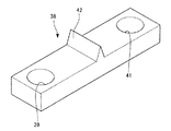
次に、図8及び図9を参照してアース棒について説明する。図8は、アース棒を示す斜視図、図9は、アース棒を太陽電池モジュールに取り付け状態を示す斜視図である。
図8に示すように、アース棒38は、略直方体状の導電性を有する材料で形成されている。そして、アース棒38は、2つの固定孔39,41と、位置決め突起42が設けられている。
1-2. Earth Rod Next, the earth rod will be described with reference to FIGS. FIG. 8 is a perspective view showing a ground bar, and FIG. 9 is a perspective view showing a state where the ground bar is attached to the solar cell module.
As shown in FIG. 8, the
第1の固定孔39は、長手方向の一端部に形成されており、第2の固定孔41は、長手方向の他端部に形成されている。位置決め突起42は、アース棒38の長手方向の略中央に配設されている。この位置決め突起42は、断面形状が略三角形に形成されているが、四角形や他の形状に形成してもよい。この位置決め突起42は、アース棒38を挿入穴29に挿入した際に第3の枠材9に当接する。これにより、第3の枠材9の脚部24に設けた固定孔28と、アース棒38に設けた第1の固定孔39又は第2の固定孔41の位置決めを行うことができる。
The
なお、位置決め突起42をアース棒38の長手方向の略中央に配設した例を説明したが、これに限定されるものではなく、長手方向の一側又は他側に位置決め突起42を配設してもよい。
Although the example in which the
そして、脚部24の固定孔28とアース棒38の第1の固定孔39又は第2の固定孔41を固定ネジ44で螺合することで、枠材6とアース棒38が固定される。これにより、太陽電池モジュール1の枠材6とアース棒38が固定ネジ44を介して電気的に接続される。
The
図9に示すように、このアース棒38のうち第1の固定孔39側が、傾斜方向Yに沿って配設される2つの太陽電池モジュール1A,1Bのうち下側に配設される第1の太陽電池モジュール1Aの挿入穴29に挿入される。そして、アース棒38のうち第2の固定孔41側が、傾斜方向Yの上側に配設される第2の太陽電池モジュール1Bの挿入穴29に挿入される。これにより、一つのアース棒38と固定ネジ44によって2つの太陽電池モジュール1A,1Bを電気的に接続することができる。
As shown in FIG. 9, the first fixing
更に、アース棒38は、第1の太陽電池モジュール1Aと第2の太陽電池モジュール1Bの傾斜方向Yの位置決めを行うガイドとしての役割を有している。これにより、太陽電池モジュール1の傾斜方向Yの目地を揃えることができると共に太陽電池モジュール1の配設作業の効率を向上させることが可能である。
Furthermore, the
なお、本例では、図3に示すように、2つの第3の枠材9の両側にアース棒38を取り付けた例を説明したが、アース棒38は、2つの第3の枠材9のうち少なくとも片側に取り付ければよい。
In this example, as shown in FIG. 3, the example in which the ground bars 38 are attached to both sides of the two
1−3.ゴムガスケット
次に、ゴムガスケット2について説明する。
図5に示すように、このゴムガスケット2は、弾性を有しており、覆い部46と、嵌入部47とから構成されている。そして、図2に示すように、ゴムガスケット2は、横方向Xに沿って配設された2つの太陽電池モジュール1,1の間に形成された隙間を埋めるように、傾斜方向Yに沿って2つの太陽電池モジュールの間に嵌め込まれている。
1-3. Rubber gasket Next, the
As shown in FIG. 5, the
具体的には、図5に示すように、ゴムガスケット2は、横方向Xに沿って配設された2つの太陽電池モジュール1A,1Cにおける第3の枠材9の略全体を覆うように配設される。これにより、横方向Xに沿って配設された2つの太陽電池モジュール1A,1Cの間から野地板Mに水が侵入することを防ぐことができる。
Specifically, as shown in FIG. 5, the
覆い部46は、2つの太陽電池モジュール1A,1Cの突出部23の略全体を覆うような形状に形成されている。この覆い部46は、突出部23を覆った際に、横方向Xの略中央から両端にかけて傾斜している。これにより、ゴムガスケット2に水Wが溜まることなく、太陽電池パネル3側に排水することができる。
The
嵌入部47は、覆い部46における排水面側と反対側の面で、且つ横方向Xの略中央に設けられている。嵌入部47は、第1の太陽電池モジュール1Aの突出部23と、第3の太陽電池モジュール1Cの突出部23の間に嵌め込まれている。
The
また、ゴムガスケット2を2つの太陽電池モジュール1A,1Cの突出部23の間に嵌め込んだ際に、突出部23とゴムガスケット2との間に第2の通水路48が形成される。図6に示すように、この第2の通水路48は、傾斜方向Yに沿って延在している。また、ゴムガスケット2の覆い部46は、第1の枠材7と第2の枠材8の横方向Xの両端部まで覆っている。そして、第1の通水路21と第2の通水路48は、第3の枠材9の第3の嵌合部22を間に挟んで連通している。そのため、第1の通水路21を流れる水Wが、切り欠き17aから太陽電池パネル3側に流れずに第3の嵌合部22の上面部22aを乗り越えた場合には、第2の通水路48に流れる。
Further, when the
本例では、止水部材の一具体例としてゴムからなるガスケットを設けた例を説明したが、止水部材は、例えば弾性を有する樹脂で形成されたガスケットを用いてもよい。 In this example, an example in which a gasket made of rubber is provided as a specific example of the water-stopping member, but the water-stopping member may be a gasket formed of, for example, an elastic resin.
次に、図10を参照して複数の太陽電池モジュールの配線の接続状態について説明する。図10は、複数の太陽電池モジュールにおける正極端子及び負極端子の接続状態を示す平面図である。 Next, the connection state of the wiring of a plurality of solar cell modules will be described with reference to FIG. FIG. 10 is a plan view showing a connection state of positive and negative terminals in a plurality of solar cell modules.
この図10に示すように、配線ケーブル31,32は、複数の太陽電池モジュール1の横方向Xの一側に配設された第3の枠材9から横方向Xの一側に引き出されている。そして、傾斜方向Yの上側に配設された太陽電池モジュール1の正極端子33と、傾斜方向Yの下側に配設された太陽電池モジュール1の負極端子34が接続されている。また、傾斜方向Yの一端に配設された太陽電池モジュール1の負極端子34は、横方向Xに配設され、且つ傾斜方向Yの他端に配設された太陽電池モジュール1の正極端子33と不図示の延長ケーブルを用いて接続される。
As shown in FIG. 10, the
これにより、傾斜方向Yに沿って並べられた複数の太陽電池モジュール1は、全て直列に接続される。なお、太陽電池ユニット10は、全ての太陽電池モジュール1を直列に接続しなくてもよく、複数の太陽電池モジュール1を任意の数ごとに分けて直列に接続させてもよい。
Thereby, all the several
2.太陽電池ユニットの組み立て
次に、上述したような構成を有する太陽電池ユニット10の組み立て方法について、図9、図10に基づいて説明する。
この太陽電池ユニット10は、複数の太陽電池モジュール1を野地板Mの傾斜方向Yに沿って1列ずつ配設されるものである。まず、図9に示すように、傾斜方向Yの下側に配設される第1の太陽電池モジュール1Aの脚部24の挿入穴29にアース棒38を挿入する。ここで、アース棒38には、位置決め突起42が設けられている。そのため、第1の太陽電池モジュール1Aの脚部24の固定孔28とアース棒38の第1の固定孔39の位置合わせを容易に行うことができる。また、アース棒38が傾斜方向Yに沿って滑り落ちることを防止することができる。
2. Next, a method for assembling the
In this
次に、アース棒38が挿入された第1の太陽電池モジュール1Aを野地板Mに固定ネジ44を用いて固定する。これにより、第1の太陽電池モジュール1Aの設置が完了する。なお、予め図5に示すように、2つの配線ケーブル31,32は、第3の枠材9の接続部26に設けた貫通孔27aを貫通させている。
Next, the first
また、固定孔28は、脚部24の傾斜面に設けられているため、突出部23が邪魔になることなく工具を挿入することができる。その結果、太陽電池モジュール1の固定作業の効率を向上させることが可能である。更に、脚部24の横方向Xの長さを突出部23よりも短く設定しているため、太陽電池モジュール1を正面側から見たときに脚部24に固定された固定ネジ44を突出部23で隠すことできる。
Moreover, since the fixing
次に、傾斜方向Yの他側、すなわち第1の太陽電池モジュール1Aの上側に位置する第2の太陽電池モジュール1Bを配設する。具体的には、第2の太陽電池モジュール1Bの挿入穴29にアース棒38が挿入されるように、第2の太陽電池モジュール1Bを配置する。このとき、図4に示すように、第2の太陽電池モジュール1Bのカバー部17が第1の太陽電池モジュール1Aの突起部12を覆い、且つカバー部17の先端が第1の太陽電池モジュール1Aの第1の枠材7に接近する。これにより、カバー部17と第1の太陽電池モジュール1Aにおける第1の嵌合部11の上面部11aとの間に第1の通水路21が形成される。
Next, the second solar cell module 1B located on the other side of the tilt direction Y, that is, on the upper side of the first
ここで、第2の太陽電池モジュール1Bにおける上面部16aは、円弧状に形成されており、傾斜方向Yの他端側から一端側にかけて太陽電池パネル3に近づく方向に傾斜している。
Here, the
また、第1の通水路21を、第1の嵌合部11の上面に形成したことで、第1の太陽電池モジュール1Aの第1の嵌合部11における接続面部11cと第2の太陽電池モジュール1Bの第2の嵌合部16における接続面部16cとを接触させることができる。これにより、第1の太陽電池モジュール1Aの太陽電池パネル3と第2の太陽電池モジュール1Bの太陽電池パネル3との間隔を狭くすることができる。
Moreover, the 1st
そして、第2の太陽電池モジュール1Bを野地板Mに固定ネジ44を用いて固定する。このとき、アース棒38を介して第1の太陽電池モジュール1Aと第2の太陽電池モジュール1Bは電気的接続される。また、上述したように、アース棒38が第2の太陽電池モジュール1Bを配置するガイドとなる。その結果、第1の太陽電池モジュール1Aと第2の太陽電池モジュール1Bの傾斜方向Yの目地を揃えることができる。
Then, the second solar cell module 1B is fixed to the base plate M using the fixing
上述した手順を繰り返して第2の太陽電池モジュール1Bの傾斜方向Yの上側に複数の太陽電池モジュール1を配設し、傾斜方向Yに沿って並べられた太陽電池モジュール1の列を形成する。すなわち、野地板Mの軒から棟に向かって太陽電池モジュール1を配設する。
By repeating the above-described procedure, a plurality of
次に、第1の太陽電池モジュール1Aの横方向Xの一側に、第3の太陽電池モジュール1Cを配設する。そして、傾斜方向Yに沿って複数の太陽電池モジュール1の列を形成する。この太陽電池モジュール1の列の形成方法は、上述した手順と同一であるためその説明は省略する。
Next, the third solar cell module 1C is disposed on one side in the lateral direction X of the first
次に、図10に示すように、複数の太陽電池モジュール1の第3の枠材9から延出している配線ケーブル31,32を接続する。具体的には、傾斜方向Yの上側に配設された太陽電池モジュール1の正極端子33と、傾斜方向Yの下側に配設された太陽電池モジュール1の負極端子34とを接続する。さらに、傾斜方向Yの一番上側に配設された太陽電池モジュール1の負極端子34を、横方向Xの一側で、且つ傾斜方向Yの一番下側に配設された太陽電池モジュール1の正極端子33に延長コードを用いて接続する。これにより、傾斜方向Yに沿って並べられた複数の太陽電池モジュール1は、全て直列に接続される。そして、図7Bに示すように、配線ケーブル31,32に設けられ収縮部材36を収縮させて、固定部27bに嵌め込む。
Next, as shown in FIG. 10, the
正極端子33と負極端子34の接続を2つの太陽電池モジュール1列の間で行うことができるため、配線処理を広い視界で極めて容易に行うことができる。その結果、正極端子33と負極端子34の半挿し等の確認を確実に行うことができ、電気的な接続不良を確実に防止することができる。また、太陽電池ユニット10を組み立てた後においてもゴムガスケット2を取り外すことで、極めて容易にメンテナンス等を行うことができる。
Since the connection between the
次に、図2及び図5に示すように、傾斜方向に沿って並べられた太陽電池モジュール1A,1Cの間にゴムガスケット2を嵌め込む。ここで、太陽電池モジュール1における突出部23の先端側に設けられた傾斜片23bは、野地板Mに近づく方向に傾斜している。これにより、ゴムガスケット2の嵌入部47を嵌め込み易く且つ抜け難くすることができる。
Next, as shown in FIGS. 2 and 5, the
ゴムガスケット2を2つの太陽電池モジュール1の列に嵌め込むことで、突出部23とゴムガスケット2の間に第2の通水路48が形成される。このように、横方向Xに並べられた2つの太陽電池モジュール1の列の間にゴムガスケット2の嵌入部47を嵌め込むことで、ゴムガスケット2の固定を行うことができる。そのため、止水部材を固定するための固定ネジ等の部品点数を削減することができると共に取り付け作業の効率を向上させることが可能である。
By fitting the
これにより、太陽電池ユニット10の組み立てが完了する。なお、太陽電池ユニット10の組み立て方法は、上述した方法に限定されるものではなく、その他の方法で組み立ててもよい。
Thereby, the assembly of the
なお、本発明は上述しかつ図面に示した実施の形態に限定されるものではなく、特許請求の範囲に記載した発明の要旨を逸脱しない範囲内で種々の変形実施が可能である。上述した実施の形態例では、配線ケーブルを第3の枠材から引き出し、太陽電池モジュールの横方向で正極端子と負極端子を接続した例を説明したが、これに限定されるものではない。例えば、配線ケーブルを第1の枠材及び第2の枠材の下方から引き出し、太陽電池モジュールの背面側で正極端子と負極端子を接続してもよい。 The present invention is not limited to the embodiment described above and shown in the drawings, and various modifications can be made without departing from the scope of the invention described in the claims. In the embodiment described above, the example in which the wiring cable is drawn out from the third frame member and the positive electrode terminal and the negative electrode terminal are connected in the lateral direction of the solar cell module has been described. However, the present invention is not limited to this. For example, the wiring cable may be pulled out from below the first frame member and the second frame member, and the positive electrode terminal and the negative electrode terminal may be connected on the back side of the solar cell module.
更に、アース棒を用いて載置面の傾斜方向に並べられた2つの太陽電池モジュールの接地を行った例を説明したが、一つの太陽電池モジュールずつ接地を行ってもよい。また、太陽電池ユニットを家屋の屋根に配設した例を説明したが、本発明の太陽電池ユニットは、山の斜面等の水平に対して傾斜したその他各種の傾斜面(載置面)に配設できるものである。 Furthermore, although the example which earth | grounded the two solar cell modules arranged in the inclination direction of the mounting surface using the earth | ground rod was demonstrated, you may earth | ground one solar cell module one by one. Moreover, although the example which has arrange | positioned the solar cell unit on the roof of a house was demonstrated, the solar cell unit of this invention is arrange | positioned on various other inclined surfaces (mounting surface) inclined with respect to the horizontal, such as a slope of a mountain. It can be set up.
1…太陽電池モジュール、 1A…第1の太陽電池モジュール、 1B…第2の太陽電池モジュール、 1C…第3の太陽電池モジュール、 2…ゴムガスケット(止水部材)、 3…太陽電池パネル、 3a…上辺、 3b…下辺、 3c…側辺、 4…端子ボックス、 5…太陽電池セル、 6…枠材、 7…第1の枠材、 8…第2の枠材、 9…第3の枠材、 10…太陽電池ユニット、 11…第1の嵌合部、 11a,16a,22a…上面部、 11b,16b,22b…底面部、 11c,16c,22c…接続面部、 12…突起部、 16…第2の嵌合部、 17…カバー部、 17a,25…切り欠き、 21…第1の通水路、 22…第3の嵌合部、 23…突出部、 23a…突出片、 23b…傾斜片、 24…脚部、 27a…貫通孔、 27b…固定部、 28…固定孔、 29…挿入穴 31…第1の配線ケーブル、 32…第2の配線ケーブル、 33…正極端子、 34…負極端子、 36…収縮部材、 38…アース棒、 42…位置決め突起、 44…固定ネジ、 46…覆い部、 47…嵌入部、 48…第2の通水路、 M…野地板(載置面)、 W…水、 X…横方向、 Y…傾斜方向
DESCRIPTION OF
Claims (1)
前記複数の太陽電池モジュールは、
複数の太陽電池セルを有すると共に四角形の平板状に形成された太陽電池パネルと、
前記太陽電池パネルの四辺のうち前記載置面に配置した際に前記傾斜方向の上側に位置する上辺と嵌合する第1の嵌合部と、前記第1の嵌合部の上面から突出する突起部と、からなる第1の枠材と、
前記太陽電池パネルの上辺と対向する下辺と嵌合する第2の嵌合部と、前記第2の嵌合部から前記載置面に近づく方向に傾斜して形成されると共に前記傾斜方向の下側に配置される太陽電池モジュールの前記第1の枠材の前記突起部を覆うことで前記第1の嵌合部の上面との間に第1の通水路を形成するカバー部と、からなる第2の枠材と、を備え、
前記太陽電池モジュールは、
前記太陽電池パネルの四辺のうち前記上辺及び前記下辺と略垂直をなす側辺と嵌合する第3の嵌合部からなる第3の枠材を有し、
前記横方向に隣り合う2つの太陽電池モジュールの前記第3の枠材との間に嵌め込まれる弾性を有する止水部材を備え、
前記止水部材は、前記横方向に隣り合う2つの太陽電池モジュールの前記第3の枠材の間に第2の通水路を形成して嵌め込まれ、
前記止水部材を嵌め込んだ際に、前記第1の通水路から流れた水が前記第2の通水路に流れる
太陽電池ユニット。 A plurality of solar cell modules arranged along the mounting direction inclined with respect to the horizontal and arranged in the inclination direction and the lateral direction orthogonal to the inclination direction,
The plurality of solar cell modules are:
A solar panel having a plurality of solar cells and formed into a rectangular flat plate; and
A first fitting portion that fits with an upper side that is located on the upper side in the inclined direction when arranged on the mounting surface among the four sides of the solar cell panel, and protrudes from the upper surface of the first fitting portion. A first frame member comprising a protrusion,
A second fitting portion that fits with a lower side opposite to the upper side of the solar cell panel; and a slope formed in a direction approaching the placement surface from the second fitting portion and below the inclined direction. A cover portion that forms a first water passage between the upper surface of the first fitting portion by covering the protruding portion of the first frame member of the solar cell module disposed on the side. A second frame member ,
The solar cell module is
A third frame member comprising a third fitting portion that is fitted to a side that is substantially perpendicular to the upper side and the lower side of the four sides of the solar cell panel;
A water stop member having elasticity fitted between the third frame members of the two solar cell modules adjacent in the lateral direction;
The water stop member is fitted to form a second water passage between the third frame members of the two solar cell modules adjacent in the lateral direction,
A solar cell unit in which water flowing from the first water passage flows into the second water passage when the water stop member is fitted .
Priority Applications (2)
| Application Number | Priority Date | Filing Date | Title |
|---|---|---|---|
| JP2009097216A JP5137892B2 (en) | 2009-04-13 | 2009-04-13 | Solar cell unit |
| PCT/JP2010/054400 WO2010119743A1 (en) | 2009-04-13 | 2010-03-16 | Solar cell unit |
Applications Claiming Priority (1)
| Application Number | Priority Date | Filing Date | Title |
|---|---|---|---|
| JP2009097216A JP5137892B2 (en) | 2009-04-13 | 2009-04-13 | Solar cell unit |
Publications (3)
| Publication Number | Publication Date |
|---|---|
| JP2010251418A JP2010251418A (en) | 2010-11-04 |
| JP2010251418A5 JP2010251418A5 (en) | 2012-05-31 |
| JP5137892B2 true JP5137892B2 (en) | 2013-02-06 |
Family
ID=42982410
Family Applications (1)
| Application Number | Title | Priority Date | Filing Date |
|---|---|---|---|
| JP2009097216A Expired - Fee Related JP5137892B2 (en) | 2009-04-13 | 2009-04-13 | Solar cell unit |
Country Status (2)
| Country | Link |
|---|---|
| JP (1) | JP5137892B2 (en) |
| WO (1) | WO2010119743A1 (en) |
Families Citing this family (6)
| Publication number | Priority date | Publication date | Assignee | Title |
|---|---|---|---|---|
| JP5857242B2 (en) * | 2012-03-16 | 2016-02-10 | パナソニックIpマネジメント株式会社 | Solar cell module and installation structure thereof |
| DE202012104361U1 (en) * | 2012-11-13 | 2014-02-18 | Habdank Pv-Montagesysteme Gmbh & Co. Kg | Mounting system for solar modules |
| DE202012104634U1 (en) * | 2012-11-29 | 2014-03-03 | Habdank Pv-Montagesysteme Gmbh & Co. Kg | Mounting system for solar modules |
| KR20150041932A (en) | 2013-10-10 | 2015-04-20 | 엘지이노텍 주식회사 | Solar cell module |
| JP6368604B2 (en) * | 2014-09-25 | 2018-08-01 | 株式会社カネカ | Solar cell module and method for installing solar cell module |
| JP6486415B2 (en) * | 2017-06-29 | 2019-03-20 | 連豐 薛 | Improved structure of solar cell roof |
Family Cites Families (8)
| Publication number | Priority date | Publication date | Assignee | Title |
|---|---|---|---|---|
| JPS5977253A (en) * | 1982-10-25 | 1984-05-02 | Hirai Giken:Kk | Energy collection roof |
| JPS6080648A (en) * | 1983-10-07 | 1985-05-08 | 日本軽金属株式会社 | Roof |
| JPH0696897B2 (en) * | 1992-10-27 | 1994-11-30 | 元旦ビューティ工業株式会社 | Solar panel mounting structure |
| JP3061508B2 (en) * | 1993-05-10 | 2000-07-10 | キヤノン株式会社 | Photovoltaic module array and fixing mechanism for photovoltaic module |
| JP3083473B2 (en) * | 1996-01-16 | 2000-09-04 | ミサワホーム株式会社 | Waterproof structure of the joint of solar energy conversion panel |
| JP4216407B2 (en) * | 1999-06-09 | 2009-01-28 | 東邦シートフレーム株式会社 | Solar panel mounting structure |
| JP2001329664A (en) * | 2000-03-15 | 2001-11-30 | Kanegafuchi Chem Ind Co Ltd | Solar cell module, generating set, installing method for generating set, and intermediate horizontal pedestal |
| JP4698089B2 (en) * | 2001-08-20 | 2011-06-08 | 京セラ株式会社 | Solar energy utilization array |
-
2009
- 2009-04-13 JP JP2009097216A patent/JP5137892B2/en not_active Expired - Fee Related
-
2010
- 2010-03-16 WO PCT/JP2010/054400 patent/WO2010119743A1/en active Application Filing
Also Published As
| Publication number | Publication date |
|---|---|
| JP2010251418A (en) | 2010-11-04 |
| WO2010119743A1 (en) | 2010-10-21 |
Similar Documents
| Publication | Publication Date | Title |
|---|---|---|
| JP5137892B2 (en) | Solar cell unit | |
| CA2654764C (en) | Interconnected solar module design and system | |
| US8789321B2 (en) | Roof structure, clamp for solar cell module, and method for mounting solar cell module | |
| JP2010065522A (en) | Solar battery tile | |
| KR101797562B1 (en) | Roof structure having prefabricated solar cell module connectors | |
| US20200403565A1 (en) | Electrical connection device for a photovoltaic system | |
| JP5574740B2 (en) | Roof structure and solar cell module eaves fitting | |
| JP2010251420A (en) | Solar cell module and solar cell unit | |
| JP2010251419A (en) | Solar cell unit | |
| JP2017204920A (en) | Solar cell module | |
| JP5131527B2 (en) | Installation structure and installation method of solar cells on the roof | |
| JP5557548B2 (en) | Roof structure | |
| JP5574739B2 (en) | ROOF STRUCTURE, SOLAR CELL MODULE MOUNTING DEVICE, AND SOLAR CELL MODULE MOUNTING METHOD | |
| JP2005282053A (en) | Photovoltaic power generator | |
| JP2016111896A (en) | Solar cell module, roof structure, and eaves fixture of solar cell module | |
| JP3942322B2 (en) | Solar cell module and roof | |
| JP6594626B2 (en) | Roof structure | |
| JP5574741B2 (en) | ROOF STRUCTURE, SOLAR CELL MODULE MOUNTING DEVICE, AND SOLAR CELL MODULE MOUNTING METHOD | |
| JP2017203277A (en) | Grounding structure of solar cell module, solar cell module, and grounding method of solar cell module | |
| US20240072723A1 (en) | A roof tile | |
| JP3296962B2 (en) | Roof panel wiring structure | |
| WO2012077703A1 (en) | Solar power generation system and connection box used therein | |
| JP2017203278A (en) | Layout structure of solar cell module, and roof structure | |
| JP2017203279A (en) | Layout structure of solar cell module | |
| JP5356276B2 (en) | ROOF STRUCTURE, SOLAR CELL MODULE MOUNTING DEVICE, AND SOLAR CELL MODULE MOUNTING METHOD |
Legal Events
| Date | Code | Title | Description |
|---|---|---|---|
| A521 | Request for written amendment filed |
Free format text: JAPANESE INTERMEDIATE CODE: A523 Effective date: 20120411 |
|
| A621 | Written request for application examination |
Free format text: JAPANESE INTERMEDIATE CODE: A621 Effective date: 20120411 |
|
| TRDD | Decision of grant or rejection written | ||
| A01 | Written decision to grant a patent or to grant a registration (utility model) |
Free format text: JAPANESE INTERMEDIATE CODE: A01 Effective date: 20121016 |
|
| A01 | Written decision to grant a patent or to grant a registration (utility model) |
Free format text: JAPANESE INTERMEDIATE CODE: A01 |
|
| A61 | First payment of annual fees (during grant procedure) |
Free format text: JAPANESE INTERMEDIATE CODE: A61 Effective date: 20121113 |
|
| R150 | Certificate of patent or registration of utility model |
Free format text: JAPANESE INTERMEDIATE CODE: R150 |
|
| FPAY | Renewal fee payment (event date is renewal date of database) |
Free format text: PAYMENT UNTIL: 20151122 Year of fee payment: 3 |
|
| LAPS | Cancellation because of no payment of annual fees |