JP5133786B2 - Objective lens unit, endoscope - Google Patents
Objective lens unit, endoscope Download PDFInfo
- Publication number
- JP5133786B2 JP5133786B2 JP2008149751A JP2008149751A JP5133786B2 JP 5133786 B2 JP5133786 B2 JP 5133786B2 JP 2008149751 A JP2008149751 A JP 2008149751A JP 2008149751 A JP2008149751 A JP 2008149751A JP 5133786 B2 JP5133786 B2 JP 5133786B2
- Authority
- JP
- Japan
- Prior art keywords
- objective lens
- lens frame
- frame
- lens group
- group
- Prior art date
- Legal status (The legal status is an assumption and is not a legal conclusion. Google has not performed a legal analysis and makes no representation as to the accuracy of the status listed.)
- Active
Links
- 230000003287 optical effect Effects 0.000 claims description 87
- 230000002093 peripheral effect Effects 0.000 claims description 41
- 238000003780 insertion Methods 0.000 claims description 40
- 230000037431 insertion Effects 0.000 claims description 40
- 125000006850 spacer group Chemical group 0.000 claims description 6
- 238000003825 pressing Methods 0.000 description 30
- 238000003384 imaging method Methods 0.000 description 17
- 239000000853 adhesive Substances 0.000 description 7
- 230000001070 adhesive effect Effects 0.000 description 7
- 238000005286 illumination Methods 0.000 description 6
- 239000002184 metal Substances 0.000 description 6
- 239000000758 substrate Substances 0.000 description 5
- 238000005452 bending Methods 0.000 description 4
- 238000002347 injection Methods 0.000 description 4
- 239000007924 injection Substances 0.000 description 4
- 238000004140 cleaning Methods 0.000 description 3
- 238000005520 cutting process Methods 0.000 description 3
- 239000000314 lubricant Substances 0.000 description 3
- 239000000463 material Substances 0.000 description 3
- XLYOFNOQVPJJNP-UHFFFAOYSA-N water Substances O XLYOFNOQVPJJNP-UHFFFAOYSA-N 0.000 description 3
- 239000012530 fluid Substances 0.000 description 2
- 238000000034 method Methods 0.000 description 2
- 230000001105 regulatory effect Effects 0.000 description 2
- 230000003014 reinforcing effect Effects 0.000 description 2
- 239000010935 stainless steel Substances 0.000 description 2
- 229910001220 stainless steel Inorganic materials 0.000 description 2
- 230000015572 biosynthetic process Effects 0.000 description 1
- 230000008602 contraction Effects 0.000 description 1
- 238000005336 cracking Methods 0.000 description 1
- 238000010586 diagram Methods 0.000 description 1
- 230000004048 modification Effects 0.000 description 1
- 238000012986 modification Methods 0.000 description 1
- 210000004400 mucous membrane Anatomy 0.000 description 1
- 230000002787 reinforcement Effects 0.000 description 1
- 239000011347 resin Substances 0.000 description 1
- 229920005989 resin Polymers 0.000 description 1
- 230000004044 response Effects 0.000 description 1
- 238000007789 sealing Methods 0.000 description 1
- 229910001285 shape-memory alloy Inorganic materials 0.000 description 1
- 238000005507 spraying Methods 0.000 description 1
Images


Description
本発明は、第1の対物レンズを保持する第1の対物レンズ枠と、変倍レンズを移動自在に保持する移動レンズ枠と、内周面に移動レンズ枠が摺動する被摺動面が形成された第2の対物レンズを保持する第2の対物レンズ枠を具備する対物レンズユニット、内視鏡に関する。 The present invention includes a first objective lens frame that holds the first objective lens, a moving lens frame that holds the zoom lens movably, and a sliding surface on which the moving lens frame slides on the inner peripheral surface. The present invention relates to an objective lens unit and an endoscope having a second objective lens frame that holds the formed second objective lens.
近年、内視鏡は、医療分野及び工業用分野において広く利用されている。内視鏡は、細長い挿入部を管路内に挿入することによって、管路内を観察することができる。 In recent years, endoscopes are widely used in the medical field and the industrial field. The endoscope can observe the inside of the duct by inserting an elongated insertion portion into the duct.
また、内視鏡、例えば電子内視鏡の挿入部における挿入方向先端側の先端部内には、管路内を観察するための対物光学系や、該対物光学系を保持する対物レンズ枠等から構成された対物レンズユニットや、CCD等の固体撮像素子を具備する撮像ユニット等が設けられているのが一般的であり、電子内視鏡は、固体撮像素子により、対物光学系によって結像された管路内の観察部位の像が撮像される構成になっている。 An endoscope, for example, an insertion portion of an electronic endoscope has a distal end on the distal end side in the insertion direction, from an objective optical system for observing the inside of a duct, an objective lens frame that holds the objective optical system, and the like. In general, an objective lens unit configured, an imaging unit including a solid-state imaging device such as a CCD, and the like are provided. An electronic endoscope is imaged by an objective optical system by a solid-state imaging device. In addition, an image of an observation site in the pipeline is captured.
さらに、対物光学系における複数の対物レンズ群の内、少なくとも1つのレンズを、対物光学系の光軸方向に対して移動自在な移動レンズとすることにより、移動レンズを光軸方向に移動させて、対物光学系の観察部位に対する焦点深度や、結像倍率、視野角等の光学特性を可変できる、例えば1倍〜100倍までの観察部位の表面に対する通常観察〜拡大観察までが可能な構成を具備するズーム内視鏡も周知であり、例えば特許文献1に開示されている。ズーム内視鏡を用いて観察を行えば、例えば医療用の内視鏡であれば、体腔内の観察部位における粘膜や毛細血管の構造等の観察を行うことができる。
Furthermore, by making at least one of the plurality of objective lens groups in the objective optical system a movable lens that is movable with respect to the optical axis direction of the objective optical system, the movable lens is moved in the optical axis direction. The optical depth, focus magnification, and viewing angle of the objective optical system can be varied. For example, the structure allows normal observation to magnified observation of the surface of the observation site from 1 to 100 times. A zoom endoscope provided is also well-known, and is disclosed in, for example,
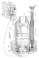
図4は、従来の対物レンズユニットを具備する内視鏡における挿入部の先端部の内部の構成を概略的に示す部分断面図である。 FIG. 4 is a partial cross-sectional view schematically showing an internal configuration of a distal end portion of an insertion portion in an endoscope including a conventional objective lens unit.
具体的には、特許文献1には、図4に示すように、内視鏡の挿入部の挿入方向Sの先端側の先端部210内に、対物光学系を構成する複数の対物レンズの内、挿入方向Sの先端側に位置する前側レンズ群220を内周面に保持する第1の対物レンズ枠221が設けられている。
Specifically, in
また、第1の対物レンズ枠221の外周面における挿入方向Sの中途位置には、階段状の段差部221dが形成されており、段差部221dの外周には、該段差部221dに形成された前側レンズ群220の径方向Rに沿った面221dmに、先端面222sが当接するように、第2の対物レンズ枠222の挿入方向Sの先端側が嵌合されている。
Further, a stepped step part 221d is formed in the middle of the insertion direction S on the outer peripheral surface of the first
第2の対物レンズ枠222は、前側レンズ群220よりも挿入方向Sの後方において、対物光学系を構成する複数の対物レンズの内、挿入方向Sの後端側に位置する後側レンズ群223を内周面に保持している。
The second
さらに、第2の対物レンズ枠222は、後側レンズ群223よりも挿入方向Sの前方であって、前側レンズ群220よりも挿入方向Sの後方の領域における内周面に、対物光学系を構成する複数の対物レンズの内、移動レンズ224を内周面に保持する移動レンズ枠225が、挿入方向Sに対して前後に摺動移動自在に嵌入されている。尚、移動レンズ枠225は、図示しないワイヤやアクチュエータ等によって、挿入方向Sに対して前後に移動自在となっている。
Furthermore, the second
また、第2の対物レンズ枠222の挿入方向Sの先端側の外周には、位置規制部材290が嵌合している。位置規制部材290は、第2の対物レンズ枠222とともに、移動レンズ枠225の挿入方向先端側の移動位置を規定している。
Further, a
また、前側レンズ群220を保持する第1の対物レンズ枠221、後側レンズ群223を保持する第2の対物レンズ枠222、移動レンズ224を保持する移動レンズ枠225、位置規制部材290により、対物レンズユニット200は構成されている。
In addition, the first
このような対物レンズユニット200の構成によれば、移動レンズ枠225が、第2の対物レンズ枠222の内周面における後側レンズ群223よりも挿入方向Sの前方であって前側レンズ群220よりも挿入方向Sの後方の領域において、図示しないワイヤやアクチュエータ等によって、挿入方向Sに対して前後に移動されることにより、対物光学系の観察部位に対する焦点深度や、結像倍率、視野角等の光学特性を可変することができる。
ところで、上述した図4に示したように、移動レンズ枠225は、第2の対物レンズ枠222の内周面において摺動移動自在に嵌合しているが、第2の対物レンズ枠222に対して移動レンズ枠225を組み付けた際、両枠間でガタ付きが発生してしまうと、第2の対物レンズ枠222の内周面に対して移動レンズ枠225が傾いてしまい、第2の対物レンズ枠222の内周面に対する移動レンズ枠225の摺動不良が生じてしまうといった問題があった。
By the way, as shown in FIG. 4 described above, the moving
尚、移動レンズ枠225の摺動不良は、通常、移動レンズ枠225、第2の対物レンズ枠222の強度を確保するため、それぞれステンレス等の金属で形成されていることから、両部材にガタ付きが生じていると余計に発生しやすい。
The sliding failure of the moving
このような問題に鑑み、移動レンズ枠225の摺動性を向上させるため、移動レンズ枠225と第2の対物レンズ枠222との間に潤滑剤を注入する構成も考えられるが、内視鏡の挿入部が体腔内に挿入されると、体腔内は体外よりも温度が高いことから、潤滑剤によって、移動レンズ224等が曇ってしまう場合があるため、使用し難いといった問題があった。
In view of such problems, a configuration in which a lubricant is injected between the moving
ここで、潤滑剤を用いずに、第2の対物レンズ枠222に対する移動レンズ枠225の摺動性を向上させる構成としては、第2の対物レンズ枠222に対する移動レンズ枠225の嵌合長を長くすることが考えらえる。両枠間の嵌合長が長くなれば、両枠間のガタ付きを最小限に抑えることができるためである。
Here, as a configuration for improving the slidability of the moving
しかしながら、特許文献1に開示された構成においては、図4に示すように、第2の対物レンズ枠222は、挿入方向Sの先端側が、第1の対物レンズ枠221の段差部221dの外周面において、先端面222sが面221dmに当接するよう嵌合されている。このことから、段差部221dの挿入方向Sに対する厚みP分、移動レンズ枠225は、第2の対物レンズ枠222の内周面に嵌合することができず、前側レンズ群220に対する後側レンズ群223の挿入方向Sにおける位置も規定されていることから、これ以上、第2の対物レンズ枠222に対する移動レンズ枠225の嵌合長を増やすことが構造上できないといった問題があった。
However, in the configuration disclosed in
さらに、特許文献1に開示された構成においては、図4に示すように、第1の対物レンズ枠221の段差部221dの面221dmに対する第2の対物レンズ枠222の先端面222sの当接によって、前側レンズ群220に対する後側レンズ群223の挿入方向Sに対する位置が規定されている。
Furthermore, in the configuration disclosed in
しかしながら、面221dmと先端面222sとの接触面積が小さいため、面221dmと先端面222sとが、径方向Rにおいて平面精度が悪く形成されていると、面221dmに対して先端面222sが少しでも傾いて当接してしまうと、両レンズ220、223間の挿入方向Sにおける位置がずれてしまうといった問題があった。即ち、面221dmと先端面222sとの接触面積が小さいため、前側レンズ群220に対する後側レンズ群223の位置出し制御がし難いといった問題があった。
However, since the contact area between the
本発明の目的は、以上の問題点に鑑みてなされたものであり、複数の対物レンズの内、第1のレンズ枠が保持する前側レンズ群に対する第2のレンズ枠が保持する後側レンズ群の位置精度を正確に確保できるとともに、第2のレンズ枠に対する移動レンズ枠のガタ付きを軽減させて、移動レンズ枠の摺動性を向上させることのできる構成を具備する対物レンズユニット、内視鏡を提供することにある。 The object of the present invention has been made in view of the above problems, and among the plurality of objective lenses, the rear lens group held by the second lens frame relative to the front lens group held by the first lens frame. An objective lens unit having a configuration capable of accurately ensuring the positional accuracy of the movable lens frame and reducing the backlash of the movable lens frame relative to the second lens frame, thereby improving the slidability of the movable lens frame. To provide a mirror.
上記目的を達成するため本発明の一態様による対物レンズユニットは、第1の対物レンズ群を保持するとともに、該第1の対物レンズ群の径方向に沿った突き当て面が形成された第1の対物レンズ枠と、前記第1の対物レンズ群と第2の対物レンズ群との間で光軸方向に沿って前後に移動させる移動レンズ枠と、内周面に前記移動レンズ枠が摺動する被摺動面を形成し、前記移動レンズ枠よりも後方に前記第2の対物レンズ群を保持する第2の対物レンズ枠と、前記第1の対物レンズ枠及び前記第2の対物レンズ枠の外周に嵌合され、先端に前記移動レンズ枠及び前記第2の対物レンズ枠の先端部を覆うように前記第1の対物レンズ群側に前記径方向に沿って折れ曲がった屈曲部が形成されるとともに、前記屈曲部の後端面に前記第2の対物レンズ枠の先端面が当接され、さらに前記屈曲部の前記突き当て面に平行な先端面が前記突き当て面に突き当てられた位置制御部材と、を具備し、前記屈曲部は、前記径方向において、前記位置制御部材の前記第2の対物レンズ枠と嵌合する部位の前記径方向の第1の肉厚に、前記第2の対物レンズ枠の前記位置制御部材と嵌合する部位の前記径方向の第2の肉厚を足した第4の肉厚よりも厚い第3の肉厚に形成されている。 In order to achieve the above object, an objective lens unit according to an aspect of the present invention includes a first objective lens group and a first abutting surface formed along a radial direction of the first objective lens group . Objective lens frame, a moving lens frame that moves back and forth along the optical axis direction between the first objective lens group and the second objective lens group, and the moving lens frame slides on the inner peripheral surface A second objective lens frame that forms a slidable surface and holds the second objective lens group behind the moving lens frame, the first objective lens frame, and the second objective lens frame. It is fitted on the outer periphery of the movable lens frame and the second of said first bent portion which is bent along the radial direction to the objective lens side so as to cover the tip portion of the objective lens frame is formed in the distal end Rutotomoni, the second objective the rear end surface of the bent portion The distal end surface of the lens frame is in contact, comprising further, a position control member parallel tip surface is abutted to the abutting surface on the abutting surface of the bent portion, the bent portion, the diameter In the direction, the first thickness in the radial direction of the portion that fits with the second objective lens frame of the position control member is the same as that of the portion that fits with the position control member of the second objective lens frame. The third thickness is greater than the fourth thickness obtained by adding the second thickness in the radial direction.
また、本発明の一態様による内視鏡は、第1の対物レンズ群を保持するとともに、該第1の対物レンズ群の径方向に沿った突き当て面が形成された第1の対物レンズ枠と、前記第1の対物レンズ群と第2の対物レンズ群との間で光軸方向に沿って前後に移動させる移動レンズ枠と、内周面に前記移動レンズ枠が摺動する被摺動面を形成し、前記移動レンズ枠よりも後方に前記第2の対物レンズ群を保持する第2の対物レンズ枠と、前記第1の対物レンズ枠及び前記第2の対物レンズ枠の外周に嵌合され、先端に前記移動レンズ枠及び前記第2の対物レンズ枠の先端部を覆うように前記第1の対物レンズ群側に前記径方向に沿って折れ曲がった屈曲部が形成されるとともに、前記屈曲部の後端面に前記第2の対物レンズ枠の先端面が当接され、さらに前記屈曲部の前記突き当て面に平行な先端面が前記突き当て面に突き当てられた位置制御部材と、を具備し、前記屈曲部は、前記径方向において、前記位置制御部材の前記第2の対物レンズ枠と嵌合する部位の前記径方向の第1の肉厚に、前記第2の対物レンズ枠の前記位置制御部材と嵌合する部位の前記径方向の第2の肉厚を足した第4の肉厚よりも厚い第3の肉厚に形成されている対物レンズユニットを、細長な挿入部の挿入方向の先端側の内部に具備する。 In addition, an endoscope according to an aspect of the present invention holds a first objective lens group and a first objective lens frame in which an abutting surface is formed along the radial direction of the first objective lens group. A moving lens frame that moves back and forth along the optical axis direction between the first objective lens group and the second objective lens group, and a sliding object in which the moving lens frame slides on the inner peripheral surface A second objective lens frame that forms a surface and holds the second objective lens group behind the moving lens frame, and is fitted to the outer periphery of the first objective lens frame and the second objective lens frame. is case, the the movement lens frame and the second bent portion which is bent along the radial direction to the first objective lens group side so as to cover the tip portion of the objective lens frame is formed at the distal end, the the distal end surface of the second objective lens frame is abutted against the rear end surface of the bent portion, Comprising a position control member to which the said abutment surface parallel to the distal end surface of the bent portion al is abutted to the abutting surface, wherein the bent portion, in the radial direction, the said position control member The second thickness in the radial direction of the portion fitted with the position control member of the second objective lens frame is added to the first thickness in the radial direction of the portion fitted with the second objective lens frame. The objective lens unit formed in a third thickness that is thicker than the fourth thickness obtained by adding is provided inside the distal end side in the insertion direction of the elongated insertion portion .
本発明によれば、複数の対物レンズの内、第1のレンズ枠が保持する前側レンズ群に対する第2のレンズ枠が保持する後側レンズ群の位置精度を正確に確保できるとともに、第2のレンズ枠に対する移動レンズ枠のガタ付きを軽減させて、移動レンズ枠の摺動性を向上させることのできる構成を具備する対物レンズユニット、内視鏡を提供することができる。 According to the present invention, among the plurality of objective lenses, the positional accuracy of the rear lens group held by the second lens frame with respect to the front lens group held by the first lens frame can be accurately ensured, and the second It is possible to provide an objective lens unit and an endoscope having a configuration capable of reducing the backlash of the moving lens frame relative to the lens frame and improving the slidability of the moving lens frame.
以下、図面を参照して本発明の実施の形態を説明する。
図1は、本実施の形態の対物レンズユニットを具備する内視鏡と周辺装置とから構成された内視鏡システムの構成の概略を示す図である。
Embodiments of the present invention will be described below with reference to the drawings.
FIG. 1 is a diagram showing an outline of a configuration of an endoscope system including an endoscope including an objective lens unit according to the present embodiment and a peripheral device.
図1に示すように、内視鏡システム1は、内視鏡2と周辺装置150とにより主要部が構成されている。内視鏡2は、操作部8と、挿入部7と、ユニバーサルコード9と、コネクタ10とから主要部が構成されている。
As shown in FIG. 1, the
周辺装置150は、光源装置3と、ビデオプロセッサ5と、モニタ6とから主要部が構成されている。また、このような構成を有する内視鏡2と周辺装置150とは、ユニバーサルコード9の先端に設けられたコネクタ10により互いに接続されている。
The
内視鏡2の操作部8に、湾曲操作ノブ14と、スイッチ17と、送気送水操作釦15と、吸引操作釦16と、グリップ部18に設けられた挿入部7内の図示しない処置具挿通路を兼ねた吸引管路に連通する処置具挿入口11bとが配設されている。
A treatment tool (not shown) in the
内視鏡2の挿入部7は、挿入方向Sの先端側(以下、単に先端側と称す)から順に、先端部12と湾曲部13と可撓管部21とにより構成されている。湾曲部13は、操作部8に設けられた湾曲操作ノブ14により湾曲操作されるものである。
The
先端部12の先端側の先端面に、後述する対物レンズユニット33における後述する前側レンズ群53(いずれも図2参照)の先端側に位置する観察窓19が配設されている。
An
また、先端部12の先端面に、観察窓19の表面に水や空気等の流体を噴きつけて観察窓19の表面を洗浄する観察窓洗浄口22と、照明窓20と、図示しない吸引管路の先端開口11aと、観察部位に対して水や空気等の流体を供給する観察物洗浄口23とが配設されている。
Further, an observation
内視鏡2のユニバーサルコード9の先端に、コネクタ10が設けられ、このコネクタ10は、接点コネクタ部10aが光源装置3に電気的に接続される。さらに、コネクタ10の電気コネクタ4bに、光源装置3をビデオプロセッサ5に電気的に接続するための接続ケーブル4の一端が電気的に接続される。尚、接続ケーブル4の他端は、ビデオプロセッサ5の電気コネクタ4aに電気的に接続される。
A
ライトガイドは、コネクタ10の接点コネクタ部10aから、ユニバーサルコード9内、操作部8内及び挿入部7内を介して先端部12内の照明窓20に近接する位置まで挿通されており、光源装置3からの照明光を照明窓20に送り、照明光を、照明窓20を介して観察部位に拡開照射するものである。
The light guide is inserted from the
また、信号ケーブル45は、先端部12内に設けられた後述する撮像素子ユニット32の後述する固体撮像素子36に電気的に接続された後述する基板41(いずれも図2参照)から、挿入部7内、操作部8内及びユニバーサルコード9内を介して、コネクタ10内の電気コネクタ4bまで挿通されており、固体撮像素子36で撮像した像の電気信号を、ビデオプロセッサ5へと伝達するものである。
Further, the
尚、ビデオプロセッサ5とモニタ6とは、図示しないケーブルにより電気的に接続されており、ビデオプロセッサ5へ固体撮像素子36から伝送された画像は、モニタ6に表示される。
Note that the video processor 5 and the
次に、先端部12内に設けられた対物レンズユニットの構成について、図2を用いて説明する。図2は、本実施の形態の対物レンズユニットを具備する撮像装置を、移動体ユニットとともに示す断面図である。
Next, the configuration of the objective lens unit provided in the
図2に示すように、撮像装置30は、対物レンズユニット33と、撮像素子ユニット32とにより主要部が構成されている。
As shown in FIG. 2, the
対物レンズユニット33は、前群レンズ枠52と、後群レンズ枠54と、可動レンズ枠56と、位置制御枠58と、前側レンズ群53、後側レンズ群55と、可動レンズ57とにより主要部が構成されている。
The
第1の対物レンズ枠である前群レンズ枠52は、光軸方向Oに沿って、第1の対物レンズ群である前側レンズ群53を内周面に保持している。
The front
また、前群レンズ枠52の光軸方向Oに沿った中途位置、具体的には、観察窓19の光軸方向Oの後端側(以下、単に後端側と称す)に、前群レンズ枠52の光軸方向Oに沿った先端側(以下、単に先端側と称す)の内周面よりも後端側の内周面の径を小さくする段差部103が形成されており、段差部103の後端側の前側レンズ群53の径方向Rに沿った面に、突き当て面79が形成されている。
Further, the front group lens is positioned at a midway position along the optical axis direction O of the front
また、前群レンズ枠52の段差部103よりも後端側の外周に、変倍レンズである可動レンズ57を前側レンズ群53よりも光軸方向Oの後方(以下、単に後方と称す)に保持する移動レンズ枠である可動レンズ枠56が嵌合されている。
In addition, on the outer periphery on the rear end side of the
可動レンズ枠56は、前側レンズ群53よりも後方において、後述する移動体ユニット34により、スイッチ17からの信号に応じて、可動レンズ57を、光軸方向Oに沿って前後に移動させるものである。
The
また、可動レンズ枠56は、後述する後群レンズ枠54の光軸方向Oに沿った範囲内であって、後述する後側レンズ群55よりも光軸方向Oの前方(以下、単に前方と称す)において、摺動移動自在となっている。
The
さらに、可動レンズ枠56の先端側及び後端側の外周における後群レンズ枠54の被摺動面54hに摺動する摺動面81は、該摺動面81の全周に沿って円形状に形成されているとともに、被摺動面54hと同形状に形成されている。
Further, the sliding
これは、可動レンズ枠56が後群レンズ枠54に対して、仮にガタ付いて組み付けられてしまった際、可動レンズ枠56の外周において被摺動面54hに接触する位置は、先端側及び後端側となる。
This is because the position where the
ここで、従来は、先端側または後端側に、可動レンズ枠56の柄が形成されていたため、可動レンズ枠56を削り出しで形成すると、柄によって先端側及び後端側における全周形状を円形状に形成できず、柄の形成に起因するカット面の角部により、被摺動面54hに対する可動レンズ枠56の摺動性が悪いといった問題があった。
Here, since the handle of the
ところが、本実施の形態のように、先端側及び後端側の摺動面81が、該摺動面81の全周に沿って円形状に形成されているとともに、被摺動面54hと同形状に形成されていると、可動レンズ枠56が後群レンズ枠54に対してガタ付いて組み付けられていたとしても、両面54h、81間の摩擦が小さくなるため、従来よりも摺動性を向上させることができる。
However, as in the present embodiment, the sliding
また、可動レンズ枠56が後群レンズ枠54に対してガタ付きなく組み付けられている場合であっても、後群レンズ枠54に対する可動レンズ枠56の摺動性は、両面54h、81間の摩擦が小さくなるため、摺動面81によって向上される。
Even when the
さらに、可動レンズ枠56の外周に、可動レンズ枠56が光軸方向Oに摺動移動する際、摺動面81が摺動する被摺動面54hが内周面に形成されるとともに、可動レンズ57よりも後方に、第2の対物レンズ群である後側レンズ群55を保持する第2の対物レンズ枠である後群レンズ枠54が嵌合されている。尚、後群レンズ枠54は、径方向Rにおいて、第2の肉厚M2に形成されている。
Furthermore, a sliding
また、後群レンズ枠54の先端側の外周に、位置制御部材である位置制御枠58が嵌合されている。位置制御枠58は、先端に、可動レンズ枠56の先端面56s及び後群レンズ枠54の先端面54sを覆うように、径方向Rに前側レンズ群53側に垂直に折れ曲がった屈曲部102を有している。
Further, a
具体的には、屈曲部102の光軸方向Oの先端面(以下、単に先端面と称す)80が、前群レンズ枠52の段差部103の突き当て面79に当接されるとともに、屈曲部102の径方向Rにおける前側レンズ群53に対向する嵌合面78が、前群レンズ枠52の段差部103よりも後端側の外周面に当接されることにより、位置制御枠58は、後群レンズ枠54の先端側の外周及び前群レンズ枠52の段差部103よりも後端側の外周面に嵌合されている。
Specifically, the front end surface (hereinafter simply referred to as the front end surface) 80 of the
従来は、上述した図4に示したように、本実施の形態における後群レンズ枠54に相当する第2の対物レンズ枠222に撮像装置30を固定するV溝101が形成されているが、本実施の形態のように、位置制御枠58に形成することで、後群レンズ枠54がネジの締め付けに伴って変形し、後群レンズ枠54と可動レンズ枠56との間にガタ付きが発生し、可動レンズ枠56の摺動性が低下してしまうことが防止されている。よって、後群レンズ枠54の外周に、位置制御枠58が嵌合されていることによっても、後群レンズ枠54と可動レンズ枠56との間に発生するガタ付きが防止されている。
Conventionally, as shown in FIG. 4 described above, the V-
また、位置制御枠58は、径方向Rにおいて、後群レンズ枠54の第2の肉厚M2よりも厚い第1の肉厚M1(M1>M2)に形成されている。これは、ネジが螺合するV溝101が形成された位置制御枠58の強度を向上させるためである。
Further, the
さらに、屈曲部102は、径方向Rにおいて、位置制御枠58の第1の肉厚M1と後群レンズ枠54の第2の肉厚M2とを足した第4の肉厚M4よりも大きな第3の肉厚M3に形成されている(M3>M1+M2=M4)。
Further, the
このことにより、上述した図4に示したように、従来の前群レンズ枠52に相当する第1の対物レンズ枠221の段差部221dの面221dmに対する、後群レンズ枠54に相当する第2の対物レンズ枠222の先端面222sの当接面積よりも、大きな当接面積を有して、屈曲部102の先端面80は、前群レンズ枠52の段差部103の突き当て面79に当接している。
Accordingly, as shown in FIG. 4 described above, the
ここで、位置制御枠58の屈曲部102の後端面104に後群レンズ枠54の先端面54sが当接している。よって、屈曲部102の先端面80が突き当て面79に当接していることにより、屈曲部102によって、前群レンズ枠52が保持する前側レンズ群53と、後群レンズ枠54が保持する後側レンズ群55との光軸方向Oの位置が規定されている。
Here, the
尚、従来においては、第2の対物レンズ枠222の先端面222sが、第1の対物レンズ枠221の段差部221dの面221dmに当接することにより、前側レンズ群に対する後側レンズ群の光軸方向Oの位置が規定されていた。
Conventionally, the front end surface 222s of the second
このことから、上述したように、屈曲部102の先端面80は、前群レンズ枠52の段差部103の突き当て面79に、従来のレンズ間の位置決めを行う枠222、221間の接触面積よりも大きな面積を以て当接していることから、言い換えれば、レンズ間の位置決めを行う先端面80と突き当て面79とは、従来のレンズ間の位置決めを行う枠222、221の面222s、221dmよりも大きな面に形成されていることから、各面80、79の平面精度を従来よりも高く形成できるため、両面79、80は精度良く当接する。よって、従来よりも前側レンズ群53に対する後側レンズ群55の位置出し制御が容易になる。
Therefore, as described above, the
また、後群レンズ枠54の先端面54sが屈曲部102の後端面104に当接しているとともに、可動レンズ枠56は、後群レンズ枠54の光軸方向Oに沿った範囲内において、被摺動面54hに嵌合していることを考慮すると、屈曲部102の光軸方向Oに沿った厚みQは、上述した図4に示した従来の第1の対物レンズ枠221の段差部221dの光軸方向Oに沿った厚みPよりも小さくなる(Q<P)。
Further, the
よって、P−Qの光軸方向Oに沿った厚さ分、本実施の形態においては、図4に示す従来よりも後群レンズ枠54に対する可動レンズ枠56の嵌合長が長くなっている。よって、後群レンズ枠54と可動レンズ枠56との間に、図4に示す従来の構成よりもガタ付きが生じ難い構成となっている。尚、屈曲部の厚みQは、薄ければ薄いほど、後群レンズ枠54に対する可動レンズ枠56の嵌合長が長くなる。
Therefore, in this embodiment, the fitting length of the
位置制御枠58の後端面に、可動レンズ枠56の柄56eの先端面が当接することにより、光軸方向Oに摺動移動する可動レンズ枠56の光軸方向Oにおける最も先端側の位置を規定する位置規定面58kが形成されている。
The position of the most distal side in the optical axis direction O of the
また、後群レンズ枠54の光軸方向Oに沿った中途位置、具体的には、位置制御枠58の後端面よりも後方に、位置調整リング59が嵌合されている。位置調整リング59は、可動レンズ枠56の柄56eの光軸方向Oに沿った後端面(以下、単に後端面と称す)が当接されることにより、光軸方向Oに摺動移動する可動レンズ枠56の光軸方向Oにおける最も後端側の位置を規定する。
Further, a
さらに、後群レンズ枠54の後方に、撮像素子ユニット32が設けられている。具体的には、後群レンズ枠54の位置調整リング59よりも後端側の外周に、撮像素子保持枠43の先端側が嵌合しており、撮像素子保持枠43の内周面には、光学レンズ42が固定されており、光学レンズ42の後端面には、光学レンズ39が貼着されている。さらに、光学レンズ39の後端面に、固体撮像素子36が貼着されている。
Further, an
また、固体撮像素子36には、基板41が電気的に接続されており、基板41には、信号ケーブル45の先端側から延出した複数本のリード線46が電気的に接続されている。
In addition, a
撮像素子保持枠43の後端側の外周に、光軸方向Oに沿って光学レンズ39、42、固体撮像素子36、基板41を覆う長さを有する補強枠49が嵌合されており、補強枠49の外周に、先端側が補強枠49の先端側とともに、撮像素子保持枠43の後端側の外周に固定され、後端側が信号ケーブル45の先端側の外周に固定された熱収縮チューブ50が、光学レンズ39、42、固体撮像素子36、基板41を覆うように被覆されている。尚、熱収縮チューブ50の内部には、封止樹脂48が充填されている。
A
ここで、上述したように、可動レンズ枠56は、移動体ユニット34により、光軸方向Oに対して前後に摺動移動自在となっている。具体的には、位置制御枠58の位置規定面58kが設けられた部位に、光軸方向Oに沿って第1の貫通孔58hが形成されており、該第1の貫通孔58hに、外周にバネ74が被覆された芯金部材75が嵌入されて芯金部材75の先端側が固定されている。
Here, as described above, the
また、可動レンズ枠56の柄56eにも、第1の貫通孔58hに対向するよう、光軸方向Oに沿って第2の貫通孔56hが形成されており、該第2の貫通孔56hには、芯金部材75の後端側が遊嵌状態で嵌入している。また、バネ74の後端面は、第2の貫通孔56hの先端面56kに固定されている。よって、バネ74は、常時可動レンズ枠56を後方に付勢している。
The
可動レンズ枠56の柄56eの後端面に、押圧部材位置制御部材70が当接しており、押圧部材位置制御部材70の内部には、光軸方向Oに所定の長さを有する押圧パイプ68の先端側が固定されている。尚、押圧部材位置制御部材70は、柄56eに対して当接離間自在となっている。また、押圧パイプ68は、後群レンズ枠54に光軸方向Oに沿って形成された第3の貫通孔54gに嵌入している。
A pressing member
押圧パイプ68の光軸方向Oに沿った中途位置の外周に、例えば金属から形成されたガイドパイプ63の先端側が、第3の貫通孔54gの内部において被覆している。尚、押圧パイプ68は、ガイドパイプ63の内部において、光軸方向Oに移動自在となっている。
On the outer periphery of the midway position along the optical axis direction O of the
ガイドパイプ63の後端側の内周に、光軸方向Oに所定の長さを有する絶縁パイプ64の先端側が嵌入されて固定されている。また、絶縁パイプ64の後端部に、カシメ部材66が固定されており、該カシメ部材66に、ケーブル67の先端側が固定されている。
A distal end side of an insulating
さらに、位置制御枠58、柄56e、押圧部材位置制御部材70、ガイドパイプ63の先端側の外周は、カバー76によって覆われており、また、ガイドパイプ63のカバー76によって覆われた部位を除く部位、絶縁パイプ64、カシメ部材66、ケーブル67の外周は、カバーチューブ73によって覆われている。
Further, the outer periphery of the
また、ガイドパイプ63の内部において、押圧パイプ68の後端面と、絶縁パイプ64の先端面との間に、バネ62が設けられている。バネ62は、常時押圧パイプ68を光軸方向Oの前方(以下、単に前方と称す)に押圧する。尚、バネ62の付勢力は、バネ74の付勢力よりも強い付勢力を有している。
In addition, a
また、ガイドパイプ63の内部、押圧パイプ68の内部及び絶縁パイプ64の内部に、光軸方向Oに沿って、ワイヤ状の形状記憶合金(以下、SMAと称す)61が挿通されている。SMA61の先端は、押圧部材位置制御部材70の内部において、押圧パイプ68の先端側に、抜け止め部材69によって固定されており、後端は、カシメ部材66に固定されている。
A wire-shaped shape memory alloy (hereinafter referred to as SMA) 61 is inserted along the optical axis direction O into the
SMA61は、該SMA61に、ケーブル67から電流が供給されると、光軸方向Oに収縮するようになっている。
The
よって、通常は、SMA61に電流が供給されない状態で、バネ62が押圧パイプ68を前方に押圧することにより、押圧部材位置制御部材70が可動レンズ枠56の柄56eに当接して、柄56eが位置制御枠58の位置規定面58kに当接することにより、可動レンズ枠56は、光軸方向Oにおいて、最も先端側に位置している。即ち、可動レンズ枠56は、可動レンズ57が最も前側レンズ群53に近接する位置に移動している。
Therefore, normally, when no current is supplied to the
この位置から、可動レンズ枠56を後方に移動させる際は、SMA61に、ケーブル67から、可動レンズ枠56の移動量に対応した電流が供給される。その結果、SMA61は、光軸方向Oに所定量収縮する。その後、可動レンズ枠56は、柄56eに押圧部材位置制御部材70が当接した状態で、バネ74に付勢されて、後群レンズ枠54の被摺動面54h内において、摺動面81が当接した状態で後方に摺動移動する。また、押圧パイプ68は、ガイドパイプ63の内部において、バネ62の前方への付勢に抗してバネ62を押し潰すように、後方に移動する。
When the
ここで、SMA61に、可動レンズ枠56が最も後端側に位置する量の電流が供給された場合には、SMA61の収縮に伴い、可動レンズ枠56は、柄56eに押圧部材位置制御部材70が当接した状態で、バネ74に付勢されて後群レンズ枠54の被摺動面54h内において、摺動面81が当接した状態で後方に摺動移動する。
Here, when the
その後、柄56eの後端面が、位置調整リング59に当接すると、可動レンズ枠56は、バネ74によって、柄56eが位置調整リング59に付勢された状態において、可動レンズ枠56の最も後端側の位置に、具体的には、可動レンズ57が後側レンズ群55に最も近接する位置に、移動位置が規定される。
Thereafter, when the rear end surface of the
尚、柄56eが位置調整リング59に当接した後は、柄56eから押圧部材位置制御部材70は離間し、押圧パイプ68が、ガイドパイプ63の内部において、バネ62の前方への付勢に抗してバネ62をさらに押し潰すように、さらに後方に移動する。
After the
最後に、SMA61への電流の供給が停止されると、押圧パイプ68は、バネ62に前方へ付勢されて、押圧部材位置制御部材70が柄56eに当接するとともに、柄56eが、位置規定面58kに当接するまで、可動レンズ枠56は、バネ74の後方への付勢に抗して、後群レンズ枠54の被摺動面54h内において、摺動面81が当接した状態で前方に移動する。
Finally, when the supply of current to the
このようにして、可動レンズ枠56は、後群レンズ枠54の内部において、摺動面81が被摺動面54hに当接した状態で、光軸方向Oの前後に摺動移動する。
In this way, the
このように、本実施の形態においては、後群レンズ枠54の外周面に、位置制御枠58が嵌合しており、位置制御枠58の先端側に、径方向Rにおいて、前側レンズ群53側に垂直に、後群レンズ枠54の先端面54s及び可動レンズ枠56の先端面56sを覆うように屈曲するとともに、先端面80が前群レンズ枠52の段差部103の突き当て面79に当接するとともに、嵌合面78が、前群レンズ枠52の段差部103よりも後端側の外周面に当接される屈曲部102が形成されていると示した。
As described above, in the present embodiment, the
また、屈曲部102の先端面80の突き当て面79に対する当接面積は、本実施の形態の前群レンズ枠に相当する従来の第1の対物レンズ枠221の段差部221dの面221dmに対する本実施の形態の後群レンズ枠に相当する従来の第2の対物レンズ枠222の先端面222sの当接面積よりも大きいと示した。
Also, the contact area of the
また、従来において、第2の対物レンズ枠222の先端面222sが第1の対物レンズ枠221の段差部221dの面221dmに当接することにより行っていた、前側レンズ群53に対する後側レンズ群55の光軸方向Oにおける位置決めを、本実施の形態においては、屈曲部102で行うと示した。具体的には、屈曲部102の後端面104に、後群レンズ枠54の先端面54sが当接するとともに、先端面80が突き当て面79に当接することにより行うと示した。
Further, in the related art, the
さらに、本実施の形態においては、可動レンズ枠56は、後群レンズ枠54の光軸方向Oに沿った範囲内であって、後側レンズ群55よりも前方において、移動自在となっていると示した。
Furthermore, in the present embodiment, the
また、後端面104に後群レンズ枠54の先端面54sが当接する屈曲部102の光軸方向Oに沿った厚みQは、本実施の形態の後群レンズ枠に相当する第2の対物レンズ枠222が当接する第1の対物レンズ枠221の段差部221dの光軸方向Oに沿った厚みPよりも小さいと示した。
Further, the thickness Q along the optical axis direction O of the
このことによれば、屈曲部102の先端面80が、突き当て面79に従来よりも大きな面積を以て当接していることから、言い換えれば、先端面80と突き当て面79とは、大きな面に形成されていることから、各面80、79を、平面精度を高くして形成できるため、先端面80と突き当て面79との当接により行う、前側レンズ群53に対する後側レンズ群55の位置出し制御が容易になる。
According to this, the
また、屈曲部102の光軸方向Oに沿った厚みQが、第1の対物レンズ枠221の段差部221dの光軸方向Oに沿った厚みPよりも小さいことにより、P−Qの光軸方向Oに沿った厚さ分、本実施の形態においては、図4に示す従来よりも後群レンズ枠54に対する可動レンズ枠56の嵌合長が長くなることから、後群レンズ枠54と可動レンズ枠56との間にガタ付きが生じ難くなる。
In addition, since the thickness Q along the optical axis direction O of the
以上から、前群レンズ枠52が保持する前側レンズ群53に対する後群レンズ枠54が保持する後側レンズ群55の位置精度を正確に確保できるとともに、後群レンズ枠54に対する可動レンズ枠56のガタ付きを軽減させて、可動レンズ枠56の摺動性を向上させることのできる構成を具備する対物レンズユニット33、内視鏡2を提供することができる。
As described above, the positional accuracy of the
尚、本実施の形態においては、移動レンズ枠56は、SMA61を具備する移動体ユニット34によって光軸方向Oに移動させると示したが、ワイヤまたはアクチュエータを具備する移動体ユニットによって移動させても構わないことは勿論である。
In the present embodiment, the moving
図3は、図2の構成とは異なる構成を有する対物レンズユニットを具備する撮像装置の変形例の構成を、移動体ユニットとともに示す断面図である。 FIG. 3 is a cross-sectional view showing a configuration of a modified example of the imaging apparatus including an objective lens unit having a configuration different from the configuration of FIG. 2 together with the moving body unit.
この図3に示す撮像装置及び移動体ユニットの構成は、上述した図2に示した撮像装置及び移動体ユニットと比して、数カ所、構成が異なる。よって、この相違点のみを説明し、図2に示した撮像装置及び移動体ユニットと同様の構成には同じ符号を付し、その説明は省略する。 The configurations of the imaging apparatus and the mobile unit shown in FIG. 3 are different from the imaging apparatus and the mobile unit shown in FIG. Therefore, only this difference will be described, and the same components as those of the imaging device and the mobile unit shown in FIG.
ところで、通常は、可動レンズ枠56の内周面は、不要光の進入による光学フレアの発生を防ぐ目的から、黒色に塗られているが、黒色に塗布する際には、塗布工程の効率化を図ると、内周面のみならず可動レンズ枠56の外周面も黒色に塗布されてしまうといった問題があった。
By the way, the inner peripheral surface of the
よって、塗布後は、外周面に塗布されてしまった黒色の材料を後の工程において削ることにより取り除いているが、切削によって、可動レンズ枠56の外周面に細かな凹凸が形成されてしまい、後群レンズ枠54の被摺動面54hに対する可動レンズ枠56の摺動性が、凹凸によって低下してしまうといった問題があった。
Therefore, after application, the black material that has been applied to the outer peripheral surface is removed by shaving in a later step, but fine irregularities are formed on the outer peripheral surface of the
このような問題に鑑み、図3に示すように、不要光の進入により光学フレアが発生しやすい可動レンズ枠56の位置のみに、具体的には、可動レンズ枠56の後端面において、可動レンズ57を平面視した状態で囲む位置のみに、フレア絞り83を設ければ、フレア絞り83によって、光学フレアが防止されるため、可動レンズ枠56を、黒色に塗布する必要がなくなることから、後群レンズ枠54の被摺動面54hに対する可動レンズ枠56の摺動性が向上する。
In view of such a problem, as shown in FIG. 3, the movable lens is provided only at the position of the
ところで、通常、光軸方向Oに摺動移動する可動レンズ枠56の光軸方向Oにおける最も後端側の位置を規定する、即ち可動レンズ57の近点位置を規定する位置調整リング59は、組立工程において、位置調整リング59が嵌合された後群レンズ枠54に形成された図示しない傾斜面を利用して光軸方向Oに組立者によって治具を用いて摺動移動されて位置が調整された後、該位置が固定されていた。
By the way, the
尚、この際、位置調整リング59の位置調整は、組立者は、可動レンズ枠56の柄56eの後端面を位置調整リング59に当接させた状態において、撮像素子ユニット32によって撮像され、モニタ6に表示された画像の解像度から判断して行っていた。
At this time, the
しかしながら、この調整方法では、組立者は、位置調整リング59を光軸方向Oに対して摺動移動させて調整することから、位置調整リング59の移動量の微調整が難しいといった問題があった。尚、位置調整リング59の微調整を行う必要があるのは、位置調整リング59は、可動レンズ57の近点位置を規定するものであることから、少しのズレでも撮像された画像の倍率や焦点が大きく変化してしまうためである。
However, in this adjustment method, the assembler slides and moves the
このような問題に鑑み、図2に示すように、位置調整リング59が嵌合される後群レンズ枠54の外周面の位置に、ネジ54nを形成し、位置調整リング59がネジ54nに螺合する構成とした。
In view of such a problem, as shown in FIG. 2, a
このことによれば、組立の際、組立者は、位置調整リング59を回転させるのみで、位置調整リング59の光軸方向Oに対する位置の微調整を行うことができることから、組立の際、可動レンズ枠56の光軸方向Oにおける最も後端側の位置を、精度良く調整することができる。尚、位置調整リング59の位置調整後は、位置調整リング59の位置は固定される。
According to this, when assembling, the assembler can finely adjust the position of the
ところで、通常、前側レンズ群53の光軸方向Oにおける最も先端側に位置する観察窓19の視野角は、140°程度であるが、観察窓19に、170°程度の広角の視野角を有するレンズを用いる場合がある。
By the way, normally, the viewing angle of the
この場合、画角が広くなることから、モニタ6に表示される撮像画像の4隅等に、黒い影(以下、ケアレと称す)が発生してしまう場合があった。よって、従来は、図3に示すように、前群レンズ枠52の段差部103の先端面と観察窓19の後端面との間に嵌入されている絞り板110の光軸方向Oに対する厚さを変えて、観察窓19と、該観察窓19以外の前側レンズ群53との光軸方向Oに対する距離を調整して画角を調整することにより、ケアレの発生を防止していた。
In this case, since the angle of view becomes wide, black shadows (hereinafter referred to as “care”) may occur at the four corners of the captured image displayed on the
しかしながら、絞り板110の厚さを変更するには、その都度、観察窓19を着脱する必要があり、レンズを着脱するのは大変作業が煩雑であるといった問題があった。
However, in order to change the thickness of the
このような問題に鑑み、図3に示すように、前群レンズ枠52の段差部103の後端面79と、位置制御枠58の屈曲部102の先端面80との間に、挿抜自在なスペーサ111を設けた。スペーサ111は、該スペーサ111の厚さを交換することによって、前側レンズ群53に対する後側レンズ群55の光軸方向Oに対する位置を調整することにより、画角を調整してケアレの発生を防止する。
In view of such a problem, as shown in FIG. 3, a spacer that can be inserted and removed between the
このような構成によれば、前群レンズ枠52に対して位置制御枠58を取り外して、スペーサ111を所定の厚さのスペーサに交換し、前群レンズ枠52に対して位置制御枠58を装着するのみで、画角の調整を行えることができることから、前群レンズ枠52から観察窓19を着脱するよりも、はるかに簡単な作業によって、画角を調整することができる。
According to such a configuration, the
ところで、従来は、図2に示すように、位置制御枠58固定用のネジが螺合されるV溝101は、位置制御枠58において、可動レンズ枠56の光軸方向Oに対する移動領域に対して平面視した状態で重畳する領域に設けられていた。
Conventionally, as shown in FIG. 2, the V-
しかしながら、この構成においては、V溝101にネジが螺合された際、位置制御枠58が変形してしまうことに伴い、後群レンズ枠54も変形してしまう場合があり、後群レンズ枠54に対する可動レンズ枠56の摺動性が低下してしまう場合があった。
However, in this configuration, when the screw is screwed into the V-
そこで、図3に示すように、V溝101を、位置制御枠58において、可動レンズ枠56の光軸方向Oに対する摺動領域とは、平面視した状態で重ならない位置に形成した。このことによれば、V溝101に対してネジが螺合され、位置制御枠58、後群レンズ枠54が変形してしまったとしても、可動レンズ枠56の移動領域外における変形となることから、可動レンズ枠56の摺動性が低下してしまうことがない。即ち、可動レンズ枠56の摺動性を向上させることができる。
Therefore, as shown in FIG. 3, the V-
ところで、上述した図2においては、熱収縮チューブ50の後端側は、信号ケーブル45の先端側の外周面に固定されると示した。ここで、熱収縮チューブ50の先端側が被覆される補強枠49の外径と、信号ケーブル45の外径との差が大きすぎると、熱収縮チューブ50が収縮し難いといた問題があった。
Incidentally, in FIG. 2 described above, the rear end side of the
そこで、補強枠49の外径と信号ケーブル45の外径との差を小さくするため、図3に示すように、例えばステンレスから形成されたケーブル保持枠47を、信号ケーブル45の先端側の外周に遊嵌状態で嵌合し、ケーブル保持枠47内に接着剤115を注入することによりケーブル保持枠47を信号ケーブル45の先端側に固定して、ケーブル保持枠47によって、熱収縮チューブ50の収縮性を向上させる構成が周知である。
Therefore, in order to reduce the difference between the outer diameter of the reinforcing
ここで、接着剤115を注入した後、注入部がケーブル保持枠47における信号ケーブル45側に形成されていると、硬化の際、接着剤115が流れ出てしまうといった問題があった。
Here, after the adhesive 115 is injected, if the injection portion is formed on the
このような問題に鑑み、図3においては、ケーブル保持枠47における接着剤115の注入部130を、信号ケーブル45から離間する位置に上向きとなる切り欠き状に設けた。このことによれば、接着剤115の注入後、接着剤115を硬化させる際、注入部130は上向きに形成されていることから、接着剤115が流れ出てしまうことを防止することができる。
In view of such a problem, in FIG. 3, the
ところで、上述したように、移動体ユニット34の押圧パイプ68は、ガイドパイプ63内を、光軸方向Oに対して移動自在であると示した。
By the way, as described above, the pressing
この際、押圧パイプ68が、ピーク材から形成されておれば、ピーク材は、金属との摺動性が良好なことから、ガイドパイプ63に対する押圧パイプ68の摺動性が向上する。また、押圧パイプ68の内部には、図3に示すように中空部87が形成されていることから、押圧パイプ68内においてSMA61が収縮しやすくなっている。
At this time, if the
ところで、移動体ユニット34においては、図2において上述したように、ガイドパイプ63の後端側は、絶縁パイプ64の外周面において嵌合されて固定されていると示した。ところが、ガイドパイプ63と絶縁パイプ64が固定されていると、SMA61の交換性が悪いといった問題があった。
By the way, in the
そこで、図3に示すように、ガイドパイプ63の後端側を、絶縁パイプ64の外周面に対し固定せずに嵌合させるとともに、カバーチューブ73の内部に、先端側がガイドパイプ63の後端側の外周を被覆し、後端側が絶縁パイプ64の外周を被覆する連結チューブ120を設けた。尚、連結チューブ120の先端側は、ガイドパイプ63の後端側の外周に固定されており、後端側は絶縁パイプ64の外周に固定されている。
Therefore, as shown in FIG. 3, the rear end side of the
このような構成によれば、SMA61を交換する際は、図3に示すK1-K1線に沿って、カバーチューブ73、連結チューブ120、絶縁パイプ64、SMA61を切断するとともに、D-D線に沿って、押圧パイプ68、SMA61を切断するのみで、容易に、ガイドパイプ63を破壊することなく、絶縁パイプ64、バネ61、押圧パイプ68、SMA61を抜き出すができ、SMA61を交換することができる。
According to such a configuration, when replacing the
尚、交換は、抜け止め69が、別途の手段により、押圧部材位置制御部材70から取り除かれた後、新しい、絶縁パイプ64、押圧パイプ68、SMA61、連結チューブ120、カバーチューブ73、抜け止め69とともに、抜き出したバネ61を再度、図3に示すように組み付けることにより行われる。
In the replacement, after the retaining
このことによれば、バネ61、ガイドパイプ63を再利用できるとともに、SMA61の交換性が向上される。
According to this, the
ところで、図2に示すように、後群レンズ枠54の内周面の保持された後側レンズ群55の最も後端側に位置するレンズは、組立の際、後側レンズ群55の後端面において露出しているため、他の部材との接触により割れやすいといった問題があった。
Incidentally, as shown in FIG. 2, the lens located on the most rear end side of the
そこで、図3に示すように、後群レンズ枠54の後端側の内周面において、後側レンズ群55の最も後端側に位置するレンズを保持するとともに、該レンズの後端面の外周近傍を被覆する間隔管125を設けた。
Therefore, as shown in FIG. 3, the innermost peripheral surface of the
このことによれば、組立の際、間隔管125により、後側レンズ群55の最も後端側に位置するレンズを保護することができることから、該レンズの割れを防止することができる。
According to this, at the time of assembling, the lens located on the most rear end side of the
2…内視鏡
7…挿入部
33…対物レンズユニット
52…前群レンズ枠(第1の対物レンズ枠)
53…前側レンズ群(第1の対物レンズ群)
54…後群レンズ枠(第2の対物レンズ枠)
54h…被摺動面
54s…先端面
55…後側レンズ群(第2の対物レンズ群)
56…可動レンズ枠(移動レンズ枠)
56s…先端面
57…可動レンズ(変倍レンズ)
58…位置制御枠(位置制御部材)
58k…位置規定面
78…屈曲部の嵌合面
79…突き当て面
80…屈曲部の先端面
81…摺動面
102…屈曲部
104…屈曲部の後端面
M1…第1の肉厚
M2…第1の肉厚
M3…第1の肉厚
M4…第1の肉厚
O…光軸方向
R…径方向
S…挿入方向
DESCRIPTION OF SYMBOLS 2 ...
53. Front lens group (first objective lens group)
54: Rear lens group frame (second objective lens frame)
54h ... sliding
56 ... Movable lens frame (moving lens frame)
56s ...
58 ... Position control frame (position control member)
58k:
Claims (6)
前記第1の対物レンズ群と第2の対物レンズ群との間で光軸方向に沿って前後に移動させる移動レンズ枠と、
内周面に前記移動レンズ枠が摺動する被摺動面を形成し、前記移動レンズ枠よりも後方に前記第2の対物レンズ群を保持する第2の対物レンズ枠と、
前記第1の対物レンズ枠及び前記第2の対物レンズ枠の外周に嵌合され、先端に前記移動レンズ枠及び前記第2の対物レンズ枠の先端部を覆うように前記第1の対物レンズ群側に前記径方向に沿って折れ曲がった屈曲部が形成されるとともに、前記屈曲部の後端面に前記第2の対物レンズ枠の先端面が当接され、さらに前記屈曲部の前記突き当て面に平行な先端面が前記突き当て面に突き当てられた位置制御部材と、
を具備し、
前記屈曲部は、前記径方向において、前記位置制御部材の前記第2の対物レンズ枠と嵌合する部位の前記径方向の第1の肉厚に、前記第2の対物レンズ枠の前記位置制御部材と嵌合する部位の前記径方向の第2の肉厚を足した第4の肉厚よりも厚い第3の肉厚に形成されていることを特徴とする対物レンズユニット。 A first objective lens frame that holds the first objective lens group and is formed with an abutting surface along the radial direction of the first objective lens group ;
A moving lens frame that moves back and forth along the optical axis direction between the first objective lens group and the second objective lens group;
A second objective lens frame that forms a slid surface on which the moving lens frame slides on an inner peripheral surface, and holds the second objective lens group behind the moving lens frame;
The first objective lens frame and is fitted on the outer periphery of the second objective lens frame, the movable lens frame and the second objective lens frame the first objective lens so as to cover the tip portion of the distal end A bent portion that is bent along the radial direction is formed on the side, and a distal end surface of the second objective lens frame is brought into contact with a rear end surface of the bent portion, and further on the abutting surface of the bent portion A position control member having a parallel tip surface abutted against the abutting surface ;
Equipped with,
The position control of the second objective lens frame is performed on the first thickness in the radial direction of the portion of the position control member to be fitted with the second objective lens frame in the radial direction. An objective lens unit having a third thickness that is greater than a fourth thickness obtained by adding a second thickness in the radial direction of a portion to be fitted with a member .
前記摺動面は全周に沿って円形状に形成されているとともに、前記被摺動面と同形状に形成されていることを特徴とする請求項1〜4のいずれか1項に記載の対物レンズユニット。 A sliding surface that slides on the sliding surface of the second lens frame is formed only on the front end side and the rear end side in the optical axis direction of the moving lens frame ,
The sliding surface with is formed in a circular shape along the entire circumference, the according to claim 1, characterized in that it is formed on the sliding surface and the same shape Objective lens unit.
Priority Applications (1)
| Application Number | Priority Date | Filing Date | Title |
|---|---|---|---|
| JP2008149751A JP5133786B2 (en) | 2008-06-06 | 2008-06-06 | Objective lens unit, endoscope |
Applications Claiming Priority (1)
| Application Number | Priority Date | Filing Date | Title |
|---|---|---|---|
| JP2008149751A JP5133786B2 (en) | 2008-06-06 | 2008-06-06 | Objective lens unit, endoscope |
Publications (3)
| Publication Number | Publication Date |
|---|---|
| JP2009294540A JP2009294540A (en) | 2009-12-17 |
| JP2009294540A5 JP2009294540A5 (en) | 2011-07-14 |
| JP5133786B2 true JP5133786B2 (en) | 2013-01-30 |
Family
ID=41542757
Family Applications (1)
| Application Number | Title | Priority Date | Filing Date |
|---|---|---|---|
| JP2008149751A Active JP5133786B2 (en) | 2008-06-06 | 2008-06-06 | Objective lens unit, endoscope |
Country Status (1)
| Country | Link |
|---|---|
| JP (1) | JP5133786B2 (en) |
Cited By (1)
| Publication number | Priority date | Publication date | Assignee | Title |
|---|---|---|---|---|
| CN106028907A (en) * | 2014-02-25 | 2016-10-12 | 奥林巴斯株式会社 | Imaging unit and endoscope |
Families Citing this family (5)
| Publication number | Priority date | Publication date | Assignee | Title |
|---|---|---|---|---|
| JP5155494B2 (en) * | 2010-11-09 | 2013-03-06 | オリンパスメディカルシステムズ株式会社 | Endoscopic imaging device |
| US8916090B2 (en) | 2011-07-07 | 2014-12-23 | Karl Storz Imaging, Inc. | Endoscopic camera component manufacturing method |
| WO2014020987A1 (en) * | 2012-07-31 | 2014-02-06 | ソニー株式会社 | Lens attachment mechanism, lens attachment method and imaging device |
| CN109044258B (en) * | 2018-09-10 | 2023-04-25 | 上海交通大学医学院附属仁济医院 | Disposable electronic ureteroscope |
| KR102278134B1 (en) | 2020-05-28 | 2021-07-16 | 재단법인 아산사회복지재단 | Optical module for obtaining image |
Family Cites Families (5)
| Publication number | Priority date | Publication date | Assignee | Title |
|---|---|---|---|---|
| JPH0434500Y2 (en) * | 1985-12-06 | 1992-08-17 | ||
| JPS6296617U (en) * | 1985-12-06 | 1987-06-19 | ||
| JPH085450Y2 (en) * | 1985-12-27 | 1996-02-14 | オリンパス光学工業株式会社 | Endoscope device |
| JP3332954B2 (en) * | 1992-07-07 | 2002-10-07 | オリンパス光学工業株式会社 | Rapid deformation piezoelectric actuator and endoscope using rapid deformation piezoelectric actuator |
| JP2000135196A (en) * | 1998-08-28 | 2000-05-16 | Olympus Optical Co Ltd | Endoscope |
-
2008
- 2008-06-06 JP JP2008149751A patent/JP5133786B2/en active Active
Cited By (1)
| Publication number | Priority date | Publication date | Assignee | Title |
|---|---|---|---|---|
| CN106028907A (en) * | 2014-02-25 | 2016-10-12 | 奥林巴斯株式会社 | Imaging unit and endoscope |
Also Published As
| Publication number | Publication date |
|---|---|
| JP2009294540A (en) | 2009-12-17 |
Similar Documents
| Publication | Publication Date | Title |
|---|---|---|
| US8360965B2 (en) | Endoscopic image pickup unit | |
| JP5133786B2 (en) | Objective lens unit, endoscope | |
| JP5155494B2 (en) | Endoscopic imaging device | |
| JP5159454B2 (en) | Imaging device | |
| JP6121066B2 (en) | Imaging unit and endoscope | |
| JP5080387B2 (en) | Lens unit | |
| JP2015112336A (en) | Endoscope system | |
| US20170296042A1 (en) | Observation optical system unit, image pickup unit, and endoscope | |
| JP5747351B2 (en) | Endoscope | |
| JP2003230532A (en) | Apparatus for taking endoscopic image | |
| JP6833471B2 (en) | Optics and endoscopes | |
| US9872611B2 (en) | Image pickup unit and endoscope | |
| JP6465438B2 (en) | Imaging unit and endoscope | |
| JP5412590B2 (en) | Endoscope imaging unit | |
| JP6062126B1 (en) | Imaging unit and endoscope | |
| JP2018120005A (en) | Objective lens unit | |
| JP5242221B2 (en) | Imaging apparatus, electronic endoscope, and assembling method of imaging apparatus | |
| US10271718B2 (en) | Image pickup unit and endoscope | |
| JP6045899B2 (en) | Endoscope confocal scanner mounting structure | |
| JP2007313364A (en) | Endoscope | |
| JP3380140B2 (en) | Endoscope objective drive mechanism | |
| JP2002122795A (en) | Endoscope equipment | |
| CN112312820A (en) | Endoscope with a detachable handle | |
| JP2005192774A (en) | Zoom endoscope | |
| JP2002119466A (en) | Endoscope |
Legal Events
| Date | Code | Title | Description |
|---|---|---|---|
| A521 | Request for written amendment filed |
Free format text: JAPANESE INTERMEDIATE CODE: A523 Effective date: 20110525 |
|
| A621 | Written request for application examination |
Free format text: JAPANESE INTERMEDIATE CODE: A621 Effective date: 20110525 |
|
| A977 | Report on retrieval |
Free format text: JAPANESE INTERMEDIATE CODE: A971007 Effective date: 20120223 |
|
| A131 | Notification of reasons for refusal |
Free format text: JAPANESE INTERMEDIATE CODE: A131 Effective date: 20120306 |
|
| A521 | Request for written amendment filed |
Free format text: JAPANESE INTERMEDIATE CODE: A523 Effective date: 20120501 |
|
| TRDD | Decision of grant or rejection written | ||
| A01 | Written decision to grant a patent or to grant a registration (utility model) |
Free format text: JAPANESE INTERMEDIATE CODE: A01 Effective date: 20121030 |
|
| A01 | Written decision to grant a patent or to grant a registration (utility model) |
Free format text: JAPANESE INTERMEDIATE CODE: A01 |
|
| A61 | First payment of annual fees (during grant procedure) |
Free format text: JAPANESE INTERMEDIATE CODE: A61 Effective date: 20121108 |
|
| FPAY | Renewal fee payment (event date is renewal date of database) |
Free format text: PAYMENT UNTIL: 20151116 Year of fee payment: 3 |
|
| R151 | Written notification of patent or utility model registration |
Ref document number: 5133786 Country of ref document: JP Free format text: JAPANESE INTERMEDIATE CODE: R151 |
|
| FPAY | Renewal fee payment (event date is renewal date of database) |
Free format text: PAYMENT UNTIL: 20151116 Year of fee payment: 3 |
|
| S111 | Request for change of ownership or part of ownership |
Free format text: JAPANESE INTERMEDIATE CODE: R313111 |
|
| R350 | Written notification of registration of transfer |
Free format text: JAPANESE INTERMEDIATE CODE: R350 |
|
| S531 | Written request for registration of change of domicile |
Free format text: JAPANESE INTERMEDIATE CODE: R313531 |
|
| R350 | Written notification of registration of transfer |
Free format text: JAPANESE INTERMEDIATE CODE: R350 |
|
| R250 | Receipt of annual fees |
Free format text: JAPANESE INTERMEDIATE CODE: R250 |
|
| R250 | Receipt of annual fees |
Free format text: JAPANESE INTERMEDIATE CODE: R250 |
|
| R250 | Receipt of annual fees |
Free format text: JAPANESE INTERMEDIATE CODE: R250 |
|
| R250 | Receipt of annual fees |
Free format text: JAPANESE INTERMEDIATE CODE: R250 |
|
| R250 | Receipt of annual fees |
Free format text: JAPANESE INTERMEDIATE CODE: R250 |
|
| R250 | Receipt of annual fees |
Free format text: JAPANESE INTERMEDIATE CODE: R250 |