JP5132171B2 - Nonvolatile semiconductor memory device and manufacturing method thereof, and semiconductor device and manufacturing method thereof - Google Patents
Nonvolatile semiconductor memory device and manufacturing method thereof, and semiconductor device and manufacturing method thereof Download PDFInfo
- Publication number
- JP5132171B2 JP5132171B2 JP2007076018A JP2007076018A JP5132171B2 JP 5132171 B2 JP5132171 B2 JP 5132171B2 JP 2007076018 A JP2007076018 A JP 2007076018A JP 2007076018 A JP2007076018 A JP 2007076018A JP 5132171 B2 JP5132171 B2 JP 5132171B2
- Authority
- JP
- Japan
- Prior art keywords
- insulating film
- conductive layer
- gate electrode
- floating gate
- layer
- Prior art date
- Legal status (The legal status is an assumption and is not a legal conclusion. Google has not performed a legal analysis and makes no representation as to the accuracy of the status listed.)
- Expired - Fee Related
Links
Images


Classifications
-
- H—ELECTRICITY
- H01—ELECTRIC ELEMENTS
- H01L—SEMICONDUCTOR DEVICES NOT COVERED BY CLASS H10
- H01L2924/00—Indexing scheme for arrangements or methods for connecting or disconnecting semiconductor or solid-state bodies as covered by H01L24/00
- H01L2924/0001—Technical content checked by a classifier
- H01L2924/0002—Not covered by any one of groups H01L24/00, H01L24/00 and H01L2224/00
Description
本発明は、電気的に書き込み、読み出し及び消去が可能な不揮発性半導体記憶装置並びにその作製方法に関する。 The present invention relates to a nonvolatile semiconductor memory device which can be electrically written, read and erased, and a manufacturing method thereof.
データを電気的に書き換え可能であり、電源を切ってもデータを記憶しておくことのできる不揮発性メモリの市場が拡大している。不揮発性メモリは、MOSFET(Metal Oxide Semiconductor Field effect transistor)と類似の構造を有し、電荷を長期間蓄積することのできる領域がチャネル形成領域上に設けられているところに特徴がある。また、不揮発性メモリの電荷蓄積領域は絶縁層上に形成され、周囲と絶縁分離されていることから浮遊ゲートとも呼ばれている。浮遊ゲート上には、さらに絶縁層を介して制御ゲートを備えている(例えば、特許文献1、特許文献2)。
The market for nonvolatile memories that can electrically rewrite data and store data even when the power is turned off is expanding. The nonvolatile memory has a structure similar to that of a MOSFET (Metal Oxide Semiconductor Field Effect Transistor) and is characterized in that a region capable of accumulating charges for a long period is provided on the channel formation region. In addition, since the charge storage region of the nonvolatile memory is formed on an insulating layer and is isolated from the surroundings, it is also called a floating gate. A control gate is further provided on the floating gate via an insulating layer (for example,
このような構造を有する所謂浮遊ゲート型の不揮発性メモリは、制御ゲートに印加する電圧により、浮遊ゲートに電荷を蓄積させ、また放出させる動作が行われる。すなわち浮遊ゲートに保持させる電荷の出し入れにより、データを記憶する仕組みになっている。具体的に、浮遊ゲートへの電荷の注入や引き抜きは、チャネル形成領域が形成される半導体層と、制御ゲートの間に高電圧を印加して行われている。このような不揮発性メモリは、シリコンウエハーに半導体記憶装置を作り込むだけでなく、ガラス基板、プラスチック基板、絶縁層を含むシリコンウエハー上に半導体記憶装置を形成する技術についても開発が行われている。 In the so-called floating gate type nonvolatile memory having such a structure, an operation for accumulating and releasing electric charge in the floating gate is performed by a voltage applied to the control gate. In other words, data is stored by taking in and out charges held in the floating gate. Specifically, the injection and extraction of charges to and from the floating gate are performed by applying a high voltage between the semiconductor layer in which the channel formation region is formed and the control gate. Such a nonvolatile memory is not only built into a semiconductor wafer on a silicon wafer, but also a technique for forming a semiconductor memory device on a silicon wafer including a glass substrate, a plastic substrate, and an insulating layer has been developed. .
特許文献2には図29に示す不揮発性半導体記憶装置が開示されている。図29の不揮発性半導体記憶装置は、絶縁体1上に、半導体層からなるチャネル領域2、ソース領域7、ドレイン領域8、第1の絶縁膜3、フローティングゲート4、第2の絶縁膜5、コントロールゲート6、ソース電極15、ドレイン電極11、ゲート電極9を有している。そして、ソース領域7、ドレイン領域8とソース電極15、ドレイン電極11はそれぞれ層間膜13に形成されたコンタクトホールを介して接するように形成されている。
従来、図29に示したような不揮発性半導体装置では、半導体層の膜厚が薄く、層間膜13と半導体層との選択比が十分でない場合には、ドライエッチングによるコンタクトホール開口時に、層間膜13だけでなく半導体層までエッチングされてしまい、コンタクト抵抗値の増大を招くという問題がある。大判のガラス基板を用いて不揮発性半導体装置を作製する場合には、さらにコンタクト抵抗値が増大してしまう。しかしながら、半導体層の膜厚を厚くすると、レーザー結晶化(LC)する際にマージンが狭くなってしまう。また、SOI基板を用いる場合に半導体層の膜厚を厚くすると、ソース領域とドレイン領域の間の寄生トランジスタを抑制することができず完全空乏層型のTFTを形成できなくなるという問題がある。
Conventionally, in the nonvolatile semiconductor device as shown in FIG. 29, when the thickness of the semiconductor layer is thin and the selective ratio between the
また、ウェットエッチングによりコンタクトホールを開口する場合は、層間膜と半導体層との選択比を限りなく高くとることができる。しかしながら、ウェットエッチングの場合、アスペクト比の高いコンタクトホールを形成することができないため高集積化が困難である。 In addition, when the contact hole is opened by wet etching, the selectivity between the interlayer film and the semiconductor layer can be increased as much as possible. However, in the case of wet etching, contact holes with a high aspect ratio cannot be formed, so that high integration is difficult.
また、層間膜を薄くしてドライエッチング開口におけるエッチングの時間を減らして半導体層のエッチングを抑える方法もあるが、層間膜を薄くした場合は、上層の配線とゲート電極の寄生容量が増えることになるため回路としての駆動能力低下に影響を与える恐れがある。 In addition, there is a method of reducing the etching time in the dry etching opening by reducing the thickness of the interlayer film, thereby suppressing the etching of the semiconductor layer. However, when the interlayer film is made thinner, the parasitic capacitance of the upper wiring and the gate electrode increases. Therefore, there is a risk of affecting the drive capability of the circuit.
上記課題を鑑み、本発明は書き込み特性及び電荷保持特性に優れた不揮発性半導体記憶装置及びその作製方法を提供することを目的とする。 In view of the above problems, an object of the present invention is to provide a nonvolatile semiconductor memory device having excellent writing characteristics and charge retention characteristics and a method for manufacturing the same.
本発明の不揮発性半導体記憶装置は、ソース領域又はドレイン領域とソース配線又はドレイン配線との間に導電層を設けることを特徴とする。また、該導電層は、制御ゲート電極を形成する導電層と同じ導電層からなる。また、該導電層を覆うように絶縁膜が設けられており、該絶縁膜は該導電層表面の一部が露出するコンタクトホールを有することを特徴とする。また、該ソース配線又はドレイン配線は、該コンタクトホールを埋めるように形成されている。 The nonvolatile semiconductor memory device of the present invention is characterized in that a conductive layer is provided between a source region or a drain region and a source wiring or a drain wiring. The conductive layer is made of the same conductive layer as the conductive layer that forms the control gate electrode. In addition, an insulating film is provided so as to cover the conductive layer, and the insulating film has a contact hole in which a part of the surface of the conductive layer is exposed. The source wiring or drain wiring is formed so as to fill the contact hole.
本発明の不揮発性半導体記憶装置は、チャネル形成領域、ソース領域及びドレイン領域を有する半導体層と、前記ソース領域及び前記ドレイン領域の一部と前記チャネル形成領域とを覆う第1の絶縁膜と、前記第1の絶縁膜上に形成された浮遊ゲート電極と、前記浮遊ゲート電極を覆う第2の絶縁膜と、前記第2の絶縁膜上に形成された制御ゲート電極と、前記ソース領域及び前記ドレイン領域上に形成された導電層と、前記第2の絶縁膜、前記制御ゲート電極及び前記導電層上に形成された第3の絶縁膜と、前記第3の絶縁膜に形成されたコンタクトホールを介して前記導電層と接するソース電極又はドレイン電極と、を有し、前記ソース領域又は前記ドレイン領域と前記ソース電極又は前記ドレイン電極とは、前記導電層を介して電気的に接続することを特徴とする。 The nonvolatile semiconductor memory device of the present invention includes a semiconductor layer having a channel formation region, a source region, and a drain region, a first insulating film that covers a part of the source region and the drain region, and the channel formation region, A floating gate electrode formed on the first insulating film; a second insulating film covering the floating gate electrode; a control gate electrode formed on the second insulating film; the source region; A conductive layer formed on the drain region, a second insulating film, a third insulating film formed on the control gate electrode and the conductive layer, and a contact hole formed in the third insulating film A source electrode or a drain electrode in contact with the conductive layer via the conductive layer, and the source region or the drain region and the source electrode or the drain electrode are electrically connected via the conductive layer. Characterized in that it connects.
本発明の不揮発性半導体記憶装置は、チャネル形成領域、ソース領域及びドレイン領域を有する半導体層と、ソース領域及びドレイン領域の一部と前記チャネル領域とを覆う第1の絶縁膜と、前記第1の絶縁膜上に形成された浮遊ゲート電極と、前記浮遊ゲート電極を覆う第2の絶縁膜と、前記第2の絶縁膜上に形成された制御ゲート電極と、前記ソース領域及び前記ドレイン領域上に形成された導電層と、前記第2の絶縁膜、前記制御ゲート電極及び前記導電層上に形成された第3の絶縁膜と、前記第3の絶縁膜に形成されたコンタクトホールを介して前記導電層と接するソース電極又はドレイン電極と、を有し、前記ソース領域又は前記ドレイン領域と前記ソース電極又は前記ドレイン電極とは、前記導電層を介して電気的に接続し、前記制御ゲート電極は、前記第2の絶縁膜を介して前記浮遊ゲート電極を覆うように形成され、前記制御ゲート電極にはサイドウォールが形成され、前記サイドウォールは前記浮遊ゲート電極によって生じた前記制御ゲート電極の段差部分に形成されていることを特徴とする。 The nonvolatile semiconductor memory device of the present invention includes a semiconductor layer having a channel formation region, a source region, and a drain region, a first insulating film that covers a part of the source region and drain region, and the channel region, and the first A floating gate electrode formed on the first insulating film; a second insulating film covering the floating gate electrode; a control gate electrode formed on the second insulating film; and the source region and the drain region Through a conductive layer formed on the second insulating film, a third insulating film formed on the second insulating film, the control gate electrode and the conductive layer, and a contact hole formed in the third insulating film. A source electrode or a drain electrode in contact with the conductive layer, and the source region or the drain region and the source electrode or the drain electrode are electrically connected through the conductive layer, and The control gate electrode is formed so as to cover the floating gate electrode through the second insulating film, and a sidewall is formed on the control gate electrode, and the sidewall is generated by the floating gate electrode. It is formed in the level | step-difference part of a gate electrode, It is characterized by the above-mentioned.
本発明の不揮発性半導体記憶装置の作製方法は、半導体層に、チャネル形成領域、ソース領域及びドレイン領域を形成し、前記ソース領域及び前記ドレイン領域と前記チャネル形成領域とを覆って第1の絶縁膜を形成し、前記第1の絶縁膜上に浮遊ゲート電極を形成し、前記浮遊ゲート電極を覆って第2の絶縁膜を形成し、前記第1の絶縁膜と前記第2の絶縁膜の一部をエッチングして、前記ソース領域及び前記ドレイン領域の一部を露出させ、前記第2の絶縁膜、前記露出した前記ソース領域及び前記ドレイン領域上に第1の導電層を形成し、前記第1の導電層をエッチングして、前記第2の絶縁膜上に制御ゲート電極と前記露出した前記ソース領域及び前記ドレイン領域上に第2の導電層を形成し、前記第2の絶縁膜、前記制御ゲート電極及び前記第2の導電層上に第3の絶縁膜を形成し、前記第3の絶縁膜に、前記第2の導電層の一部が露出するコンタクトホールを開口し、前記露出した第2の導電層上に、ソース電極又はドレイン電極を形成することを特徴とする。 In the method for manufacturing a nonvolatile semiconductor memory device of the present invention, a channel formation region, a source region, and a drain region are formed in a semiconductor layer, and the first insulation is formed so as to cover the source region, the drain region, and the channel formation region. A film is formed, a floating gate electrode is formed on the first insulating film, a second insulating film is formed to cover the floating gate electrode, and the first insulating film and the second insulating film are formed. Etching a part to expose a part of the source region and the drain region, forming a first conductive layer on the second insulating film, the exposed source region and the drain region, Etching the first conductive layer to form a control gate electrode on the second insulating film and a second conductive layer on the exposed source and drain regions, and to form the second insulating film, Control gate power And forming a third insulating film on the second conductive layer, opening a contact hole in the third insulating film through which a part of the second conductive layer is exposed, and exposing the exposed second A source electrode or a drain electrode is formed over the conductive layer.
本発明の不揮発性半導体記憶装置の作製方法は、半導体層に、チャネル形成領域、ソース領域及びドレイン領域を形成し、前記ソース領域及び前記ドレイン領域と前記チャネル形成領域とを覆って第1の絶縁膜を形成し、前記第1の絶縁膜上に浮遊ゲート電極を形成し、前記浮遊ゲート電極を覆って第2の絶縁膜を形成し、前記第1の絶縁膜と前記第2の絶縁膜の一部をエッチングして、前記ソース領域及び前記ドレイン領域の一部を露出させ、前記第2の絶縁膜、前記露出した前記ソース領域及び前記ドレイン領域上に第1の導電層を形成し、前記第1の導電層上に第3の絶縁膜を形成し、前記第3の絶縁膜をエッチングして前記浮遊ゲート電極によって生じた段差部分にサイドウォールを形成し、前記第1の導電層をエッチングして、前記第2の絶縁膜上に制御ゲート電極と前記露出した前記ソース領域及び前記ドレイン領域上に第2の導電層を形成し、前記第2の絶縁膜、前記制御ゲート電極及び前記第2の導電層上に第4の絶縁膜を形成し、前記第4の絶縁膜に、前記第2の導電層の一部が露出するコンタクトホールを開口し、前記露出した第2の導電層上に、ソース電極又はドレイン電極を形成することを特徴とする。 In the method for manufacturing a nonvolatile semiconductor memory device of the present invention, a channel formation region, a source region, and a drain region are formed in a semiconductor layer, and the first insulation is formed so as to cover the source region, the drain region, and the channel formation region. A film is formed, a floating gate electrode is formed on the first insulating film, a second insulating film is formed to cover the floating gate electrode, and the first insulating film and the second insulating film are formed. Etching a part to expose a part of the source region and the drain region, forming a first conductive layer on the second insulating film, the exposed source region and the drain region, A third insulating film is formed on the first conductive layer, the third insulating film is etched to form a sidewall at a stepped portion generated by the floating gate electrode, and the first conductive layer is etched. Before A control gate electrode is formed on the second insulating film, and a second conductive layer is formed on the exposed source and drain regions, and the second insulating film, the control gate electrode, and the second conductive layer are formed. A fourth insulating film is formed thereon, a contact hole in which a part of the second conductive layer is exposed is opened in the fourth insulating film, and a source electrode is formed on the exposed second conductive layer. Alternatively, a drain electrode is formed.
なお、前記浮遊ゲート電極の材料として、ゲルマニウム若しくはゲルマニウム化合物、ゲルマニウム若しくはゲルマニウム化合物の酸化物若しくは窒化物、又はゲルマニウム若しくはゲルマニウム化合物を含む酸化物若しくは窒化物を用いることを特徴とする。 Note that germanium or a germanium compound, an oxide or nitride of germanium or a germanium compound, or an oxide or nitride containing a germanium or a germanium compound is used as a material for the floating gate electrode.
また、前記浮遊ゲート電極は、第1の浮遊ゲート電極及び第2の浮遊ゲート電極との積層構造を有することを特徴とする。 The floating gate electrode has a stacked structure of a first floating gate electrode and a second floating gate electrode.
なお、前記第1の浮遊ゲート電極は前記第1の絶縁膜側に設けられ、前記第1の浮遊ゲート電極上に第1の浮遊ゲート電極よりも幅が短い第2の浮遊ゲート電極が設けられることを特徴とする。 The first floating gate electrode is provided on the first insulating film side, and a second floating gate electrode having a width shorter than that of the first floating gate electrode is provided on the first floating gate electrode. It is characterized by that.
なお、前記第1の浮遊ゲート電極の材料として、ゲルマニウム若しくはゲルマニウム化合物、ゲルマニウム若しくはゲルマニウム化合物の酸化物若しくは窒化物、又はゲルマニウム若しくはゲルマニウム化合物を含む酸化物若しくは窒化物を用い、前記第2の浮遊ゲート電極の材料として、シリコン若しくはシリコン化合物を用いることを特徴とする。 Note that as the material of the first floating gate electrode, germanium or a germanium compound, an oxide or nitride of germanium or a germanium compound, or an oxide or nitride containing a germanium or a germanium compound is used, and the second floating gate is used. Silicon or a silicon compound is used as an electrode material.
ソース領域又はドレイン領域とソース配線又はドレイン配線との間に導電層を設けることにより、絶縁層をエッチングしてコンタクトホールを形成する際に、半導体層までエッチングされることがなくなり、コンタクト抵抗値の増大を防ぐことができる。よって、低電圧で高効率な書き込みをすることが出来、且つ電荷保持特性のよい不揮発性半導体記憶装置を作製することが可能となる。 By providing a conductive layer between the source region or the drain region and the source wiring or the drain wiring, when the contact hole is formed by etching the insulating layer, the semiconductor layer is not etched and the contact resistance value is reduced. An increase can be prevented. Therefore, it is possible to manufacture a nonvolatile semiconductor memory device capable of writing with high efficiency at a low voltage and having good charge retention characteristics.
また、ソース領域又はドレイン領域とソース配線又はドレイン配線との間に設けられた導電層は、制御ゲート電極材料を用いて形成されるため、生産性を損なうことなく特性の優れた不揮発性半導体記憶装置を製造することができる。当該導電層は、制御ゲート電極と同じ工程で作製することができるため、製造設備に負担を強いることなく、低電圧で高効率な書き込みをすることが出来、且つ電荷保持特性のよい不揮発性半導体記憶装置を作製することが可能となる。 In addition, since the conductive layer provided between the source region or the drain region and the source wiring or the drain wiring is formed using the control gate electrode material, the nonvolatile semiconductor memory having excellent characteristics without impairing the productivity. The device can be manufactured. Since the conductive layer can be manufactured in the same process as the control gate electrode, it is possible to perform high-efficiency writing at a low voltage without imposing a burden on manufacturing equipment, and a nonvolatile semiconductor with good charge retention characteristics A memory device can be manufactured.
本発明の実施の形態について、図面を用いて以下に説明する。但し、本発明は以下の説明に限定されず、本発明の趣旨及びその範囲から逸脱することなくその形態及び詳細を様々に変更し得ることは当業者であれば容易に理解される。従って、本発明は以下に示す実施の形態の記載内容に限定して解釈されるものではない。なお、以下に説明する本発明の構成において、同じものを指す符号は異なる図面間で共通して用いる場合がある。なお、以下に示す実施の形態1〜3、実施例1〜3は自由に組み合わせて用いることができる。
Embodiments of the present invention will be described below with reference to the drawings. However, the present invention is not limited to the following description, and it is easily understood by those skilled in the art that modes and details can be variously changed without departing from the spirit and scope of the present invention. Therefore, the present invention should not be construed as being limited to the description of the embodiments below. Note that in the structures of the present invention described below, the same reference numerals may be used in common in different drawings. Note that
(実施の形態1)
図1は本発明に係る不揮発性半導体記憶装置の主要な構成を説明するための断面図である。図1は、特に不揮発性メモリ素子の要部を示している。
(Embodiment 1)
FIG. 1 is a cross-sectional view for explaining a main configuration of a nonvolatile semiconductor memory device according to the present invention. FIG. 1 particularly shows the main part of the nonvolatile memory element.
図1において、10は基板、12は下地絶縁膜、14は半導体層、29はチャネル形成領域、18a、18bはソース領域又はドレイン領域、16は第1の絶縁膜(トンネル絶縁膜ともいう)、20は浮遊ゲート電極、22は第2の絶縁膜(コントロール絶縁膜ともいう)、24は制御ゲート電極、26a、26bは導電層、28a、28bは導電層26a、26bを介してソース領域又はドレイン領域18a、18bと電気的に接続するソース電極又はドレイン電極、28cは制御ゲート電極と電気的接続をするゲート配線、27はパッシベーション用の絶縁膜を示している。
In FIG. 1, 10 is a substrate, 12 is a base insulating film, 14 is a semiconductor layer, 29 is a channel formation region, 18a and 18b are source regions or drain regions, 16 is a first insulating film (also referred to as a tunnel insulating film), 20 is a floating gate electrode, 22 is a second insulating film (also called a control insulating film), 24 is a control gate electrode, 26a and 26b are conductive layers, and 28a and 28b are source regions or drains via the
図1に示す構成では、基板10上に下地絶縁膜12が形成され、下地絶縁膜12上にはソース領域又はドレイン領域18a、18b、チャネル形成領域29を有する半導体層14が形成され、半導体層14上に第1の絶縁膜16、導電層26a、26bが形成され、第1の絶縁膜16上に浮遊ゲート電極20が形成され、浮遊ゲート電極20及び第1の絶縁膜16上に第2の絶縁膜22が形成され、第2の絶縁膜22上には制御ゲート電極24が形成されている。ソース電極又はドレイン電極28a、28bは絶縁膜27に形成されたコンタクトホールを介してソース領域又はドレイン領域18a、18bに電気的に接続され、ゲート配線28cは絶縁膜27に形成されたコンタクトホールを介して制御ゲート電極24に電気的に接続されている。なお、ソース電極又はドレイン電極28a、28bとソース領域又はドレイン領域18a、18bとは、導電層26a、26bを介して電気的に接続されている。なお、絶縁膜27上に平坦化用の絶縁膜を形成してもよい。
In the configuration shown in FIG. 1, a base
次に、図1に示す不揮発性メモリ素子の作製方法について説明する。 Next, a method for manufacturing the nonvolatile memory element illustrated in FIGS.
まず、絶縁表面を有する基板10上に、半導体層14を形成する(図2(A))。基板10と半導体層14の間には、下地絶縁膜12を設けてもよい(図2(A))。この下地絶縁膜12は、基板10から半導体層14へアルカリ金属などの不純物が拡散して汚染することを防ぐものであり、ブロッキング層として適宜設ければよい。
First, the
絶縁表面を有する基板10としては、ガラス基板、石英基板、サファイア基板、セラミック基板、表面に絶縁膜が形成された金属基板などを用いることができる。
As the
下地絶縁膜12としては、CVD法やスパッタリング法等を用いて、酸化シリコン、窒化シリコン、酸化窒化シリコン(SiOxNy)(x>y)、窒化酸化シリコン(SiNxOy)(x>y)等の絶縁材料を用いて形成する。例えば、下地絶縁膜12を2層構造とする場合、第1層目の絶縁膜として窒化酸化シリコン膜を形成し、第2層目の絶縁膜として酸化窒化シリコン膜を形成するとよい。また、第1層目の絶縁膜として窒化シリコン膜を形成し、第2層目の絶縁膜として酸化シリコン膜を形成してもよい。
As the
半導体層14は、単結晶半導体又は多結晶半導体で形成されたものを用いることが好ましい。例えば、基板10上にスパッタリング法、プラズマCVD法若しくは減圧CVD法によって基板10の全面に形成された半導体層を結晶化させた後、選択的にエッチングして半導体層14を形成する。すなわち、素子分離の目的から、絶縁表面に島状の半導体層を形成し、該半導体層に一又は複数の不揮発性メモリ素子を形成することが好ましい。半導体材料としては、シリコンが好ましく、その他にシリコンゲルマニウム半導体を用いることもできる。半導体層の結晶化法としては、レーザー結晶化法、瞬間熱アニール(RTA)又はファーネスアニール炉を用いた熱処理による結晶化法、結晶化を助長する金属元素を用いる結晶化法又はこれら方法を組み合わせて行う方法を採用することができる。また、このような薄膜プロセスに換えて、絶縁表面に単結晶半導体層を形成した所謂SOI(Silicon on Insulator)基板を用いても良い。
The
このように、絶縁表面に形成された半導体層を島状に分離形成することで、同一基板上にメモリ素子アレイと周辺回路を形成した場合にも、有効に素子分離をすることができる。すなわち、10V以上20V以下の電圧で書き込みや消去を行う必要のあるメモリ素子アレイと、3V以上7V以下の電圧で動作してデータの入出力や命令の制御を主として行う周辺回路を同一基板上に形成した場合でも、各素子に印加する電圧の違いによる相互の干渉を防ぐことができる。 Thus, by separating and forming the semiconductor layer formed on the insulating surface in an island shape, even when the memory element array and the peripheral circuit are formed on the same substrate, the element can be effectively separated. That is, a memory element array that needs to be written or erased at a voltage of 10 V or more and 20 V or less and a peripheral circuit that operates at a voltage of 3 V or more and 7 V or less and mainly performs data input / output and command control on the same substrate. Even when formed, mutual interference due to a difference in voltage applied to each element can be prevented.
次に、半導体層14表面に第1の絶縁膜16を形成する(図2(B))。第1の絶縁膜16は酸化シリコン若しくは酸化シリコンと窒化シリコンの積層構造で形成する。第1の絶縁膜16は、プラズマCVD法や減圧CVD法により絶縁膜を堆積することで形成しても良いが、好ましくはプラズマ処理による固相酸化若しくは固相窒化で形成すると良い。半導体層(代表的にはシリコン層)を、プラズマ処理により酸化又は窒化することにより形成した絶縁膜は、緻密で絶縁耐圧が高く信頼性に優れているためである。第1の絶縁膜16は、浮遊ゲート電極20に電荷を注入するためのトンネル絶縁膜として用いるので、このように丈夫であるものでが好ましい。この第1の絶縁膜16は8nm以上20nm以下、好ましくは8nm以上10nm以下の厚さに形成することが好ましい。例えば、ゲート長を600nmとする場合、第1の絶縁膜16は8nm以上10nm以下の厚さに形成することができる。
Next, a first insulating
プラズマ処理による固相酸化処理若しくは固相窒化処理として、マイクロ波(代表的には2.45GHz)で励起され、電子密度が1×1011cm−3以上1×1013cm−3以下、且つ電子温度が0.5eV以上1.5eV以下のプラズマを利用することが好ましい。固相酸化処理若しくは固相窒化処理において、500℃以下の温度において、緻密な絶縁膜を形成すると共に実用的な反応速度を得るためである。 As solid-phase oxidation treatment or solid-phase nitridation treatment by plasma treatment, the electron density is 1 × 10 11 cm −3 or more and 1 × 10 13 cm −3 or less when excited by microwaves (typically 2.45 GHz), and It is preferable to use plasma having an electron temperature of 0.5 eV to 1.5 eV. This is because in the solid phase oxidation treatment or solid phase nitridation treatment, a dense insulating film is formed at a temperature of 500 ° C. or lower and a practical reaction rate is obtained.
このプラズマ処理により半導体層14の表面を酸化する場合には、酸素雰囲気下(例えば、酸素(O2)又は一酸化二窒素(N2O)と希ガス(He、Ne、Ar、Kr、Xeの少なくとも一つを含む)雰囲気下、若しくは酸素又は一酸化二窒素と水素(H2)と希ガス雰囲気下)で行う。また、プラズマ処理により窒化をする場合には、窒素雰囲気下(例えば、窒素(N2)と希ガス(He、Ne、Ar、Kr、Xeの少なくとも一つを含む)雰囲気下、窒素と水素と希ガス雰囲気下、若しくはNH3と希ガス雰囲気下)でプラズマ処理を行う。本実施の形態では、希ガスとして例えばArを用いることができる。また、ArとKrを混合したガスを用いてもよい。
When the surface of the
図4にプラズマ処理を行うための装置の構成例を示す。このプラズマ処理装置は、基板10を配置するための支持台88と、ガスを導入するためのガス供給部84、ガスを排気するために真空ポンプに接続する排気口86、アンテナ80、誘電体板82、プラズマ発生用のマイクロ波を供給するマイクロ波供給部92を有している。また、支持台88に温度制御部90を設けることによって、基板10の温度を制御することも可能である。
FIG. 4 shows a configuration example of an apparatus for performing plasma processing. This plasma processing apparatus includes a
以下に、プラズマ処理について説明する。なお、プラズマ処理とは、半導体層、絶縁膜、導電層に対する酸化処理、窒化処理、酸窒化処理、水素化処理、表面改質処理を含んでいる。これらの処理は、その目的に応じて、ガス供給部84から供給するガスを選択すればよい。
Hereinafter, the plasma treatment will be described. Note that plasma treatment includes oxidation treatment, nitridation treatment, oxynitridation treatment, hydrogenation treatment, and surface modification treatment for a semiconductor layer, an insulating film, and a conductive layer. For these processes, a gas supplied from the
酸化処理若しくは窒化処理を行うには以下のようにすれば良い。まず、処理室内を真空にし、ガス供給部84から酸素又は窒素を含むプラズマ処理用ガスを導入する。基板10は室温若しくは温度制御部90により100℃以上550℃以下に加熱する。なお、基板10と誘電体板82との間隔は、20nm以上80mm以下(好ましくは20nm以上60mm以下)程度である。次に、マイクロ波供給部92からアンテナ80にマイクロ波を供給する。そしてマイクロ波をアンテナ80から誘電体板82を通して処理室内に導入することによって、プラズマ94を生成する。マイクロ波の導入によりプラズマの励起を行うと、低電子温度(3eV以下、好ましくは1.5eV以下)で高電子密度(1×1011cm−3以上)のプラズマを生成することができる。この高密度プラズマで生成された酸素ラジカル(OHラジカルを含む場合もある)及び/又は窒素ラジカル(NHラジカルを含む場合もある)によって、半導体層の表面を酸化又は窒化することができる。プラズマ処理用ガスにアルゴンなどの希ガスを混合させると、希ガスの励起種により酸素ラジカルや窒素ラジカルを効率良く生成することができる。この方法は、プラズマで励起した活性なラジカルを有効に使うことにより、500℃以下の低温で固相反応による酸化、窒化若しくは酸化窒化を行うことができる。
The oxidation treatment or nitridation treatment may be performed as follows. First, the processing chamber is evacuated and a plasma processing gas containing oxygen or nitrogen is introduced from the
図2(B)において、プラズマ処理により形成される好適な第1の絶縁膜16の一例は、酸化雰囲気下のプラズマ処理により半導体層14表面に8nm以上10nm以下の厚さで酸化シリコン層を形成し、その後窒素雰囲気下でその酸化シリコン層の表面を窒化プラズマで処理した窒素プラズマ処理層を形成した積層構造とする。具体的には、まず、酸素雰囲気下でのプラズマ処理により半導体層14上に8nm以上10nm以下の厚さで酸化シリコン層を形成する。その後、続けて窒素雰囲気下でプラズマ処理を行うことにより酸化シリコン層の表面又は表面近傍に窒素濃度の高い窒素プラズマ処理層を設ける。なお、表面近傍とは、酸化シリコン層の表面から概略0.5nm〜1.5nmの深さをいう。例えば、窒素雰囲気下でプラズマ処理を行うことによって、酸化シリコン層の表面から概略1nmの深さに窒素を20〜50原子%の割合で含有させた構造とする。
In FIG. 2B, an example of a suitable first insulating
いずれにしても、上記のようなプラズマ処理による固相酸化処理若しくは固相窒化処理を用いることで、耐熱温度が700℃以下のガラス基板を用いても、950℃以上1050℃以下程度の加熱で形成される熱酸化膜と同等な絶縁膜を得ることができる。すなわち、不揮発性メモリ素子のトンネル絶縁膜として信頼性の高いトンネル絶縁膜を形成することができる。 In any case, by using a solid phase oxidation treatment or solid phase nitridation treatment by plasma treatment as described above, even if a glass substrate having a heat resistant temperature of 700 ° C. or less is used, it can be heated at about 950 ° C. to 1050 ° C. or less. An insulating film equivalent to the thermal oxide film to be formed can be obtained. That is, a highly reliable tunnel insulating film can be formed as the tunnel insulating film of the nonvolatile memory element.
続いて、第1の絶縁膜16上に導電層25を形成する(図2(C))。そして、導電層25を選択的にエッチングすることにより、第1の絶縁膜16上に浮遊ゲート電極20を形成する(図2(D))。浮遊ゲート電極20は、タンタル(Ta)、チタン(Ti)、モリブデン(Mo)、タングステン(W)、クロム(Cr)、シリコン(Si)、ゲルマニウム(Ge)から選ばれた元素でなる膜、または前記元素の窒化物でなる膜(代表的には窒化タンタル膜、窒化タングステン膜、窒化チタン膜)、または前記元素を組み合わせた合金膜(代表的にはMo−W合金、Mo−Ta合金)、または前記元素のシリサイド膜(代表的にはタングステンシリサイド膜、チタンシリサイド膜、ニッケルシリサイド膜)を用いることができる。前記シリコン膜に対しては、リンやボロンなどの不純物を添加してもよい。単層の導電層で形成しても良いが、二層、三層といった積層膜としてもよい。スパッタ法又はCVD法により形成する。
Subsequently, a
なお、好ましくは、浮遊ゲート電極20を形成する半導体材料のバンドギャップが、半導体層14のバンドギャップより小さいことが好ましい。半導体層14の伝導帯の底のエネルギーレベルより、浮遊ゲート電極20の伝導帯の底のエネルギーレベルを低くすることにより、キャリア(電子)の注入性を向上させ、電荷保持特性を向上させるためである。
Note that the band gap of the semiconductor material forming the floating
また、浮遊ゲート電極20を形成する半導体材料は、半導体層14を形成する材料よりも抵抗率が小さい材料で形成されていることが好ましい。浮遊ゲート電極20を抵抗率の小さい半導体材料で形成することにより、制御ゲート電極と半導体層の間に電圧を印加したとき、電界が浮遊ゲート電極で印加電圧が分圧されずにすみ、電界を半導体層に有効に作用させることができる。例えば、ゲルマニウムは40〜70Ω・cmの固有抵抗を有するので好ましい。また、抵抗率を下げる目的で浮遊ゲート電極20にn型不純物を添加しても良い。このように、半導体層14と比較して、浮遊ゲート電極20をバンドギャップが小さく抵抗率が低い材料で形成することで、書き込み特性を向上させることができる。
The semiconductor material forming the floating
また、浮遊ゲート電極20を形成する半導体材料は、第1の絶縁層16により形成される半導体層14の電子に対する障壁エネルギーに対し、第1の絶縁層16により形成される浮遊ゲート電極20の電子に対する障壁エネルギーが高くなるものであることが好ましい。半導体層14から浮遊ゲート電極20へのキャリア(電子)を注入しやすくし、浮遊ゲート電極20から電荷が消失することを防ぐためである。
The semiconductor material forming the floating
このような条件を満たすものとして、代表的にはゲルマニウム若しくはゲルマニウム化合物で浮遊ゲート電極20を形成することができる。ゲルマニウム化合物の代表例としては、シリコンゲルマニウムであり、この場合シリコンに対してゲルマニウムが10原子%以上含まれていることが好ましい。ゲルマニウムの濃度が10原子%以下であると、構成元素としての効果が薄れ、バンドギャップが有効に小さくならないためである。
Typically, the floating
浮遊ゲートは電荷を蓄積する目的で、本発明に係る不揮発性半導体記憶装置に適用されるが、同様の機能を備えるものであれば他の半導体材料を適用することもできる。例えば、ゲルマニウムを含む三元系の半導体であっても良い。また、当該半導体材料が水素化されていても良い。また、不揮発性メモリ素子の電荷蓄積層としての機能を持つものとして、当該ゲルマニウム若しくはゲルマニウム化合物の酸化物若しくは窒化物、又は当該ゲルマニウム若しくはゲルマニウム化合物を含む酸化物若しくは窒化物の層で置き換えることもできる。 The floating gate is applied to the nonvolatile semiconductor memory device according to the present invention for the purpose of accumulating electric charges, but other semiconductor materials can be applied as long as they have the same function. For example, a ternary semiconductor containing germanium may be used. Further, the semiconductor material may be hydrogenated. Further, as a function of a charge storage layer of a nonvolatile memory element, an oxide or nitride of the germanium or germanium compound, or an oxide or nitride layer containing the germanium or germanium compound can be used. .
また、浮遊ゲート電極20を、第1の浮遊ゲート電極と第2の浮遊ゲート電極の積層構造で設けてもよい。なお、その場合、好ましくは、第1の絶縁層16側に設けられる第1の浮遊ゲート電極は、ゲルマニウム若しくはゲルマニウム化合物等で形成し、第2の絶縁層22側に設ける第2の浮遊ゲート電極層は、シリコン若しくはシリコン化合物で形成するとよい。シリコン化合物としては、窒化シリコン、窒化酸化シリコン、炭化シリコン、ゲルマニウムを10原子%未満の濃度で含むシリコンゲルマニウム、金属窒化物、金属酸化物などを適用することができる。シリコン若しくはシリコン化合物は、ゲルマニウム若しくはゲルマニウム化合物よりもエネルギーギャップが大きい。このように、第2の浮遊ゲート電極層を、第1の浮遊ゲート電極層よりもバンドギャップの大きな材料で形成することにより、浮遊ゲートに蓄積する電荷が第2の絶縁層22側にリークするのを防ぐことができる。また、第2の浮遊ゲート電極層を形成するものとして、金属窒化物又は金属酸化物を用いることができる。金属窒化物としては、窒化タンタル、窒化タングステン、窒化モリブデン、窒化チタンなどを用いることができる。金属酸化物としては、酸化タンタル、酸化チタン、酸化スズなどを用いることができる。
Further, the floating
いずれにしても、上記したシリコン若しくはシリコン化合物、金属窒化物又は金属酸化物の第2の浮遊ゲート電極は、ゲルマニウム若しくはゲルマニウム化合物で形成される第1の浮遊ゲート電極の上層側に設けることにより、製造工程においては、耐水性や耐薬品性を目的としたバリア層として用いることができる。それにより、フォトリソ工程、エッチング工程、洗浄工程における基板の扱いが容易となり、生産性を向上させることができる。すなわち、浮遊ゲートの加工を容易なものとすることができる。ただし、第1の浮遊ゲート電極、第2の浮遊ゲート電極材料はこれらに限られるものではない。また、浮遊ゲート電極は2層以上の積層構造としてもよい。 In any case, by providing the second floating gate electrode of silicon or silicon compound, metal nitride, or metal oxide described above on the upper layer side of the first floating gate electrode formed of germanium or germanium compound, In the production process, it can be used as a barrier layer for the purpose of water resistance and chemical resistance. Thereby, the handling of the substrate in the photolithography process, the etching process, and the cleaning process becomes easy, and the productivity can be improved. That is, the floating gate can be easily processed. However, the material of the first floating gate electrode and the second floating gate electrode is not limited to these. The floating gate electrode may have a stacked structure of two or more layers.
次に、浮遊ゲート電極20をマスクとして、半導体層14に不純物元素を導入することによって、ソース領域又はドレイン領域18a、18bを形成する(図2(D)参照)。不純物元素としては、n型を付与する不純物元素又はp型を付与する不純物元素を用いる。n型を示す不純物元素としては、リン(P)やヒ素(As)等を用いることができる。p型を示す不純物元素としては、ボロン(B)やアルミニウム(Al)やガリウム(Ga)等を用いることができる。p型不純物として、例えばホウ素を用いた場合、5×10¹⁵atoms/cm3以上1×1016atoms/cm3以下の濃度で添加する。これは、トランジスタのしきい値電圧を制御するためのものであり、チャネル形成領域29に添加されることで有効に作用する。チャネル形成領域29は、後述する浮遊ゲート電極20の下方に形成されるものであり、半導体層14の一対のソース領域又はドレイン領域18a、18bの間に位置するものである。
Next, an impurity element is introduced into the
次に、浮遊ゲート電極20上に、第2の絶縁膜22を形成する(図3(A))。第2の絶縁膜22は、酸化シリコン、酸化窒化シリコン(SiOxNy)(x>y)、窒化シリコン(SiNx)、窒化酸化シリコン(SiNxOy)(x>y)、酸化アルミニウム(AlxOy)、HfOx、又はTaOxなどの一層若しくは複数層を、減圧CVD法やプラズマCVD法などで形成する。第2の絶縁膜22は20nm以上60nm以下、好ましくは30nm以上40nm以下の膜厚で形成する。例えば、酸化シリコン層を8nmの膜厚で形成し、その上に窒化シリコン層を2nmの膜厚で形成し、その上に酸化窒化シリコン膜を30nmの膜厚で形成した積層膜を用いることができる。また、浮遊ゲート電極20にプラズマ処理を行い、その表面を窒化処理した窒化膜を形成してもよい。いずれにしても、第1の絶縁膜16と第2の絶縁膜22が、浮遊ゲート電極20と接する側の一方又は双方を窒化膜若しくは窒化処理された層とすることで、浮遊ゲート電極20の酸化を防ぐことができる。
Next, a second insulating
次に、第1の絶縁膜16及び第2の絶縁膜22を選択的にエッチングして、ソース領域又はドレイン領域18a、18bの表面の一部が露出するように、第1の絶縁膜16及び第2の絶縁膜22を除去する(図3(B))。半導体層14上に、浮遊ゲート電極20の上方を覆い、ソース領域又はドレイン領域18a、18bの一部を覆うようにレジスト316を形成する。そして、エッチングによりソース領域又はドレイン領域18a、18bの一部が露出するように第1の絶縁膜16及び第2の絶縁膜22を除去する。
Next, the first insulating
次に、第2の絶縁膜22、ソース領域又はドレイン領域18a、18b上に、導電層19を形成する(図3(C))。そして、導電層19を選択的にエッチングして除去することによって、半導体層14の上方の一部に導電層19を残存させ、チャネル形成領域29上に制御ゲート電極24を、ソース領域又はドレイン領域18a、18b上に第1の導電層26a、26bを形成する(図3(D))。制御ゲート電極24及び第1の導電層26a、26bは、タンタル(Ta)、タングステン(W)、チタン(Ti)、モリブデン(Mo)、クロム(Cr)、ニオブ(Nb)等から選択された金属、又はこれらの金属を主成分とする合金材料若しくは化合物材料で形成することが好ましい。また、リン等の不純物元素を添加した多結晶シリコンを用いることができる。また、一層又は複数層の金属窒化物層24aと上記の金属層24bの積層構造で制御ゲート電極24を形成しても良い。金属窒化物としては、窒化タングステン、窒化モリブデン、窒化チタンを用いることができる。金属窒化物層24aを設けることにより、金属層24bの密着性を向上させることができ、剥離を防止することができる。また、窒化タンタルなどの金属窒化物は仕事関数が高いので、第2の絶縁膜22との相乗効果により、第1の絶縁膜16の厚さを厚くすることができる。なお、導電層26a、26bは、第1の絶縁膜16又は第2の絶縁膜22の一部を覆うように形成されていてもよい。
Next, a
次に、制御ゲート電極24及び第1の導電層26a、26b上に、コンタクトホール315を有する第3の絶縁膜27を形成する(図3(E))。第3の絶縁膜27は、CVD法やスパッタ法等により、酸化珪素(SiOx)、窒化珪素(SiNx)、酸化窒化珪素(SiOxNy)(x>y)、窒化酸化珪素(SiNxOy)(x>y)等の酸素または窒素を有する絶縁膜やDLC(ダイヤモンドライクカーボン)等の炭素を含む膜、エポキシ、ポリイミド、ポリアミド、ポリビニルフェノール、ベンゾシクロブテン、アクリル等の有機材料またはシロキサン樹脂等のシロキサン材料からなる単層または積層構造で設けることができる。なお、シロキサン材料とは、Si−O−Si結合を含む材料に相当する。シロキサンは、シリコン(Si)と酸素(O)との結合で骨格構造が構成される。置換基として、少なくとも水素を含む有機基(例えばアルキル基、芳香族炭化水素)が用いられる。置換基として、フルオロ基を用いることもできる。または置換基として、少なくとも水素を含む有機基と、フルオロ基とを用いてもよい。
Next, a third insulating
なお、コンタクトホール315は、第3の絶縁膜27上にレジストマスクを形成し、ドライエッチングすることにより導電層26a、26bの一部が露出するように形成する。本実施の形態では、ソース領域又はドレイン領域18a、18b上に導電層26a、26bを設けるため、コンタクトホール315を形成するエッチングの際に、ソース領域又はドレイン領域として機能する半導体層までエッチングされることがない。
Note that the
次に、第3の絶縁膜27に形成されたコンタクトホールを介して、第1の導電層26a、26bと接するようにソース電極又はドレイン電極(第2の導電層)28a、28bを形成する。(図3(E))。また、制御ゲート電極24と接するようにゲート配線28cを形成する。なお、ソース領域又はドレイン領域18a、18bとソース電極又はドレイン電極28a、28bとは、第1の導電層26a、26bを介して電気的に接続している。ソース電極又はドレイン電極28a、28b、ゲート配線28cは、CVD法やスパッタリング法等により、アルミニウム(Al)、タングステン(W)、チタン(Ti)、タンタル(Ta)、モリブデン(Mo)、ニッケル(Ni)、白金(Pt)、銅(Cu)、金(Au)、銀(Ag)、マンガン(Mn)、ネオジウム(Nd)、炭素(C)、シリコン(Si)から選択された元素、又はこれらの元素を主成分とする合金材料若しくは化合物材料で、単層又は積層の膜を形成した後、エッチングすることにより形成する。アルミニウムを主成分とする合金材料とは、例えば、アルミニウムを主成分としニッケルを含む材料、又は、アルミニウムを主成分とし、ニッケルと、炭素と珪素の一方又は両方とを含む合金材料に相当する。
Next, source or drain electrodes (second conductive layers) 28 a and 28 b are formed so as to be in contact with the first
ソース電極又はドレイン電極28a、28bは、例えば、バリア膜とアルミニウムシリコン(Al−Si)膜とバリア膜の積層構造、バリア膜とアルミニウムシリコン(Al−Si)膜と窒化チタン(TiN)膜とバリア膜の積層構造を採用するとよい。なお、バリア膜とは、チタン、チタンの窒化物、モリブデン、又はモリブデンの窒化物からなる薄膜に相当する。アルミニウムやアルミニウムシリコンは抵抗値が低く、安価であるため、ソース電極又はドレイン電極28a、28bを形成する材料として最適である。また、上層と下層のバリア層を設けると、アルミニウムやアルミニウムシリコンのヒロックの発生を防止することができる。また、還元性の高い元素であるチタンからなるバリア膜を形成すると、結晶質半導体層上に薄い自然酸化膜ができていたとしても、この自然酸化膜を還元し、結晶質半導体層と良好なコンタクトをとることができる。
The source or
図1に示すような構造を有する不揮発性メモリ素子は、ソース領域又はドレイン領域18a、18bとソース電極又はドレイン電極28a、28bとの間に導電層26a、26bが設けられている。よって、第3の絶縁膜27をエッチングする際に、半導体層までエッチングされることがなくなり、コンタクト抵抗値の増大を防ぐことができる。よって、低電圧で高効率な書き込みをすることが出来、且つ電荷保持特性のよいメモリを作製することが可能となる。
In the nonvolatile memory element having the structure shown in FIG. 1,
このような不揮発性メモリ素子を用いて、様々な態様の不揮発性半導体記憶装置を得ることができる。図5に不揮発性メモリセルアレイの等価回路の一例を示す。1ビットの情報を記憶するメモリセルMS01は、選択トランジスタS01と不揮発性メモリ素子M01で構成されている。不揮発性メモリ素子M01は、図1に示す構造を有するメモリ素子である。なお、図5において、不揮発性メモリ素子M01〜M03、M11〜M13はそれぞれ図1に示す構造を有する不揮発性メモリ素子である。不揮発性メモリ素子M01〜M03、M11〜M13はそれぞれ選択トランジスタS01〜S03、S11〜S13によって制御される。なお、不揮発性メモリ素子又は選択トランジスタの個数は図5に示すものに限られない。 Various nonvolatile semiconductor memory devices can be obtained using such a nonvolatile memory element. FIG. 5 shows an example of an equivalent circuit of a nonvolatile memory cell array. The memory cell MS01 that stores 1-bit information includes a selection transistor S01 and a nonvolatile memory element M01. The nonvolatile memory element M01 is a memory element having the structure shown in FIG. In FIG. 5, nonvolatile memory elements M01 to M03 and M11 to M13 are nonvolatile memory elements having the structure shown in FIG. The nonvolatile memory elements M01 to M03 and M11 to M13 are controlled by selection transistors S01 to S03 and S11 to S13, respectively. Note that the number of nonvolatile memory elements or selection transistors is not limited to that shown in FIG.
選択トランジスタS01は、ビット線BL0と不揮発性メモリ素子M01の間に直列に挿入され、ゲートがワード線WL1に接続されている。不揮発性メモリ素子M01のゲートはワード線WL11に接続されている。不揮発性メモリ素子M01にデータを書き込むときは、ワード線WL1とビット線BL0をHレベル、BL1をLレベルとして、ワード線WL11に高電圧を印加する。それにより、浮遊ゲートに電荷が蓄積されて、不揮発性メモリ素子にデータを書き込むことができる。データを消去する場合には、ワード線WL1とビット線BL0をHレベルとし、ワード線WL11に負の高電圧を印加すればよい。 The selection transistor S01 is inserted in series between the bit line BL0 and the nonvolatile memory element M01, and the gate is connected to the word line WL1. The gate of the nonvolatile memory element M01 is connected to the word line WL11. When data is written to the nonvolatile memory element M01, the word line WL1 and the bit line BL0 are set to the H level and BL1 is set to the L level, and a high voltage is applied to the word line WL11. Thereby, charges are accumulated in the floating gate, and data can be written into the nonvolatile memory element. When erasing data, the word line WL1 and the bit line BL0 are set to H level, and a negative high voltage is applied to the word line WL11.
このメモリセルMS01において、選択トランジスタS01と不揮発性メモリ素子M01をそれぞれ、絶縁表面に島状に分離して形成された半導体層30、32で形成することにより、素子分離領域を特段設けなくても、他の選択トランジスタ若しくは不揮発性メモリ素子との干渉を防ぐことができる。また、メモリセルMS01内の選択トランジスタS01と不揮発性メモリ素子M01は共にnチャネル型なので、この両者を一つの島状に分離した半導体層で形成することにより、この二つの素子を接続する配線を省略することができる。 In this memory cell MS01, the select transistor S01 and the non-volatile memory element M01 are formed by the semiconductor layers 30 and 32 formed in an island shape on the insulating surface, respectively, so that no element isolation region is provided. Interference with other selection transistors or nonvolatile memory elements can be prevented. Further, since both the select transistor S01 and the nonvolatile memory element M01 in the memory cell MS01 are n-channel type, by forming both of them in a semiconductor layer separated into one island shape, a wiring for connecting the two elements is formed. Can be omitted.
図6は、ビット線に不揮発性メモリ素子を直接接続したNOR型の等価回路を示している。このメモリセルアレイは、ワード線WLとビット線BLが互いに交差して配設し、各交差部に不揮発性メモリ素子を配置している。NOR型は、個々の不揮発性メモリ素子のドレインをビット線BLに接続する。ソース線SLには不揮発性メモリ素子のソースが共通接続される。 FIG. 6 shows a NOR-type equivalent circuit in which a nonvolatile memory element is directly connected to a bit line. In this memory cell array, word lines WL and bit lines BL are arranged so as to intersect with each other, and nonvolatile memory elements are arranged at each intersection. In the NOR type, the drain of each nonvolatile memory element is connected to the bit line BL. The sources of the nonvolatile memory elements are commonly connected to the source line SL.
この場合もこのメモリセルMS01において、不揮発性メモリ素子M01を絶縁表面に島状に分離して形成された半導体層32で形成することにより、素子分離領域を特段設けなくても、他の不揮発性メモリ素子との干渉を防ぐことができる。また、複数の不揮発性メモリ素子(例えば、図6に示すM01〜M23)を一つのブロックとして扱い、これらの不揮発性メモリ素子を一つの島状に分離した半導体層で形成することにより、ブロック単位で消去動作を行うことができる。
Also in this case, in the memory cell MS01, the non-volatile memory element M01 is formed of the
NOR型の動作は、例えば、次の通りである。データ書き込みは、ソース線SLを0Vとし、データを書込むために選択されたワード線WLに高電圧を与え、ビット線BLにはデータ”0”と”1”に応じた電位を与える。例えば、”0”と”1”に対してそれぞれHレベル、Lレベルの電位をビット線BLに付与する。”0”データを書き込むべく、Hレベルが与えられた不揮発性メモリ素子ではドレイン近傍でホットエレクトロンが発生し、これが浮遊ゲートに注入される。”1”データの場合この様な電子注入は生じない。 The NOR type operation is, for example, as follows. In data writing, the source line SL is set to 0 V, a high voltage is applied to the word line WL selected for writing data, and a potential corresponding to data “0” and “1” is applied to the bit line BL. For example, H level and L level potentials are applied to the bit line BL for “0” and “1”, respectively. In order to write “0” data, in the nonvolatile memory element to which H level is given, hot electrons are generated in the vicinity of the drain, and this is injected into the floating gate. In the case of “1” data, such electron injection does not occur.
“0”データが与えられたメモリセルでは、ドレインとソースとの間の強い横方向電界により、ドレインの近傍でホットエレクトロンが生成され、これが浮遊ゲートに注入される。これにより、浮遊ゲートに電子が注入されてしきい値電圧が高くなった状態が”0”である。”1”データの場合はホットエレクトロンが生成されず、浮遊ゲートに電子が注入されずしきい値電圧の低い状態、すなわち消去状態が保持される。 In a memory cell to which “0” data is given, hot electrons are generated in the vicinity of the drain due to a strong lateral electric field between the drain and the source, and this is injected into the floating gate. As a result, the state where electrons are injected into the floating gate and the threshold voltage becomes high is “0”. In the case of “1” data, hot electrons are not generated, electrons are not injected into the floating gate, and a low threshold voltage state, that is, an erased state is maintained.
データを消去するときは、ソース線SLに10V程度の正の電圧を印加し、ビット線BLは浮遊状態としておく。そしてワード線に負の高電圧を印加して(制御ゲートに負の高電圧を印加して)、浮遊ゲートから電子を引き抜く。これにより、データ”1”の消去状態になる。 When erasing data, a positive voltage of about 10 V is applied to the source line SL, and the bit line BL is left floating. Then, a negative high voltage is applied to the word line (a negative high voltage is applied to the control gate), and electrons are extracted from the floating gate. As a result, the data “1” is erased.
データ読み出しは、ソース線SLを0Vにすると共にビット線BLを0.8V程度とし、選択されたワード線WLに、データ”0”と”1”のしきい値の中間値に設定された読み出し電圧を与え、不揮発性メモリ素子の電流引き込みの有無を、ビット線BLに接続されるセンスアンプで判定することにより行う。 For data reading, the source line SL is set to 0V and the bit line BL is set to about 0.8V, and the selected word line WL is set to an intermediate value between the threshold values of data “0” and “1”. A voltage is applied, and the presence / absence of current draw in the nonvolatile memory element is determined by a sense amplifier connected to the bit line BL.
図7は、NAND型メモリセルアレイの等価回路を示す。ビット線BLには、複数の不揮発性メモリ素子を直列に接続したNANDセルNS1が接続されている。複数のNANDセルが集まってブロックBLKを構成している。図7で示すブロックBLK1のワード線は32本である(ワード線WL0〜WL31)。ブロックBLK1の同一行に位置する不揮発性メモリ素子には、この行に対応するワード線が共通接続されている。 FIG. 7 shows an equivalent circuit of the NAND memory cell array. A NAND cell NS1 in which a plurality of nonvolatile memory elements are connected in series is connected to the bit line BL. A plurality of NAND cells gather to constitute a block BLK. The block BLK1 shown in FIG. 7 has 32 word lines (word lines WL0 to WL31). The nonvolatile memory elements located in the same row of the block BLK1 are commonly connected to word lines corresponding to this row.
この場合、選択トランジスタS1、S2と不揮発性メモリ素子M0〜M31が直列に接続されているので、これらを一つのまとまりとして一つの半導体層34で形成しても良い。それにより不揮発性メモリ素子を繋ぐ配線を省略することが出来るので、集積化を図ることができる。また、隣接するNANDセルとの分離を容易に行うことができる。また、選択トランジスタS1、S2の半導体層36とNANDセルの半導体層38を分離して形成しても良い。不揮発性メモリ素子M0〜M31の浮遊ゲートから電荷を引き抜く消去動作を行うときに、そのNANDセルの単位で消去動作を行うことができる。また、一つのワード線に共通接続する不揮発性メモリ素子(例えばM30の行)を一つの半導体層40で形成しても良い。
In this case, since the select transistors S1 and S2 and the nonvolatile memory elements M0 to M31 are connected in series, these may be formed as a
書込み動作では、NANDセルNS1が消去状態、つまりNANDセルNS1の各不揮発性メモリ素子のしきい値が負電圧の状態にしてから実行される。書込みは、ソース線SL側のメモリ素子M0から順に行う。メモリ素子M0への書込みを例として説明すると概略以下のようになる。 The write operation is executed after the NAND cell NS1 is in the erased state, that is, the threshold value of each nonvolatile memory element of the NAND cell NS1 is in a negative voltage state. Writing is performed in order from the memory element M0 on the source line SL side. An example of writing to the memory element M0 is as follows.
図8(A)は、”0”書込みをする場合、選択ゲート線SG2に例えばVcc(電源電圧)を印加して選択トランジスタS2をオンにすると共にビット線BL0を0V(接地電圧)にする。選択ゲート線SG1は0Vとして、選択トランジスタS1はオフとする。次に、メモリセルMS0のワード線WL0を高電圧Vpgm(20V程度)とし、これ以外のワード線を中間電圧Vpass(10V程度)にする。ビット線BLの電圧は0Vなので、選択されたメモリセルMS0のチャネル形成領域の電位は0Vとなる。ワード線WL0とチャネル形成領域との間の電位差が大きいため、メモリセルMS0の浮遊ゲートには前述のようにF−Nトンネル電流により電子が注入される。これにより、メモリセルMS0のしきい値電圧が正の状態(”0”が書込まれた状態)となる。 In FIG. 8A, when "0" is written, for example, Vcc (power supply voltage) is applied to the selection gate line SG2 to turn on the selection transistor S2 and to set the bit line BL0 to 0 V (ground voltage). The selection gate line SG1 is set to 0V, and the selection transistor S1 is turned off. Next, the word line WL0 of the memory cell MS0 is set to the high voltage Vpgm (about 20V), and the other word lines are set to the intermediate voltage Vpass (about 10V). Since the voltage of the bit line BL is 0V, the potential of the channel formation region of the selected memory cell MS0 is 0V. Since the potential difference between the word line WL0 and the channel formation region is large, electrons are injected into the floating gate of the memory cell MS0 by the FN tunnel current as described above. As a result, the threshold voltage of memory cell MS0 becomes positive (a state in which “0” is written).
一方”1”書込みをする場合は、図8(B)に示すように、ビット線BLを例えばVcc(電源電圧)にする。選択ゲート線SG2の電圧がVccであるため、選択トランジスタS2のしきい値電圧Vthに対して、VccマイナスVth(Vcc−Vth)になると、選択トランジスタS2がカットオフする。従って、メモリセルMS0のチャネル形成領域はフローティング状態となる。次に、ワード線WL0に高電圧Vpgm(20V)、それ以外のワード線に中間電圧Vpass(10V)の電圧を印加すると、各ワード線とチャネル形成領域との容量カップリングにより、チャネル形成領域の電圧がVcc−Vthから上昇し例えば8V程度となる。チャネル形成領域の電圧が高電圧に昇圧されるため、”0”の書込みの場合と異なり、ワード線WL0とチャネル形成領域の間の電位差が小さい。したがって、メモリセルMS0の浮遊ゲートには、F−Nトンネル電流による電子注入が起こらない。よって、メモリセルMS1のしきい値は、負の状態(”1”が書込まれた状態)に保たれる。 On the other hand, when "1" is written, the bit line BL is set to Vcc (power supply voltage), for example, as shown in FIG. Since the voltage of the selection gate line SG2 is Vcc, the selection transistor S2 is cut off when Vcc minus Vth (Vcc−Vth) with respect to the threshold voltage Vth of the selection transistor S2. Accordingly, the channel formation region of the memory cell MS0 is in a floating state. Next, when the high voltage Vpgm (20 V) is applied to the word line WL0 and the intermediate voltage Vpass (10 V) is applied to the other word lines, the capacitive coupling between each word line and the channel formation region causes the channel formation region. The voltage rises from Vcc-Vth and becomes about 8V, for example. Since the voltage of the channel formation region is boosted to a high voltage, the potential difference between the word line WL0 and the channel formation region is small unlike the case of writing “0”. Therefore, electron injection due to the FN tunnel current does not occur in the floating gate of the memory cell MS0. Therefore, the threshold value of the memory cell MS1 is maintained in a negative state (a state in which “1” is written).
消去動作をする場合は、図9(A)に示すように、選択されたブロック内の全てのワード線に負の高電圧(Vers)を印加する。ビット線BL、ソース線SLをフローティング状態とする。これにより、ブロックの全てのメモリセルにおいて浮遊ゲート中の電子がトンネル電流により半導体層に放出される。この結果、これらのメモリセルのしきい値電圧が負方向にシフトする。 In the erase operation, as shown in FIG. 9A, a negative high voltage (Vers) is applied to all the word lines in the selected block. The bit line BL and the source line SL are brought into a floating state. Thereby, electrons in the floating gate are emitted to the semiconductor layer by the tunnel current in all the memory cells of the block. As a result, the threshold voltages of these memory cells shift in the negative direction.
図9(B)に示す読み出し動作では、読出しの選択がされたメモリセルMS0のワード線WL0の電圧Vr(例えば0V)とし、非選択のメモリセルのワード線WL1〜WL31及び選択ゲート線SG1、SG2を電源電圧より少し高い読出し用中間電圧Vreadとする。すなわち、図9に示すように、選択メモリ素子以外のメモリ素子はトランスファートランジスタとして働く。これにより、読出しの選択がされたメモリセルMS0に電流が流れるか否かを検出する。つまり、メモリセルMS0に記憶されたデータが”0”の場合、メモリセルMS0はオフなので、ビット線BLは放電しない。一方、”1”の場合、メモリセルMS0はオンするので、ビット線BLが放電する。 In the reading operation shown in FIG. 9B, the voltage Vr (for example, 0 V) of the word line WL0 of the memory cell MS0 selected for reading is set, and the word lines WL1 to WL31 and the selection gate line SG1 of the non-selected memory cells are selected. SG2 is set to a read intermediate voltage Vread that is slightly higher than the power supply voltage. That is, as shown in FIG. 9, memory elements other than the selected memory element function as transfer transistors. Thus, it is detected whether or not a current flows through the memory cell MS0 selected for reading. That is, when the data stored in the memory cell MS0 is “0”, the memory cell MS0 is off, and the bit line BL is not discharged. On the other hand, when “1”, since the memory cell MS0 is turned on, the bit line BL is discharged.
図10は、不揮発性半導体記憶装置の回路ブロック図の一例を示している。不揮発性半導体記憶装置は、メモリセルアレイ52と周辺回路54が同一の基板上に形成されている。メモリセルアレイ52は、図5、図6、図7で示すような構成を有している。周辺回路54の構成は以下の通りである。
FIG. 10 shows an example of a circuit block diagram of the nonvolatile semiconductor memory device. In the nonvolatile semiconductor memory device, the
ワード線選択のためにロウデコーダ62と、ビット線選択のためにカラムデコーダ64が、メモリセルアレイ52の周囲に設けられている。アドレスは、アドレスバッファ56を介してコントロール回路58に送られ、内部ロウアドレス信号及び内部カラムアドレス信号がそれぞれロウデコーダ62及びカラムデコーダ64に転送される。
A
データ書き込み及び消去には、電源電位を昇圧した電位が用いられる。このため、コントロール回路58により動作モードに応じて制御される昇圧回路60が設けられている。昇圧回路60の出力はロウデコーダ62やカラムデコーダ64を介して、ワード線WLやビット線BLに供給される。センスアンプ66はカラムデコーダ64から出力されたデータが入力される。センスアンプ66により読み出されたデータは、データバッファ68に保持され、コントロール回路58からの制御により、データがランダムアクセスされ、データ入出力バッファ70を介して出力されるようになっている。書き込みデータは、データ入出力バッファ70を介してデータバッファ68に一旦保持され、コントロール回路58の制御によりカラムデコーダ64に転送される。
For writing and erasing data, a potential obtained by boosting the power supply potential is used. Therefore, a
このように、不揮発性半導体記憶装置では、メモリセルアレイ52において、電源電位とは異なる電位を用いる必要がある。そのため、少なくともメモリセルアレイ52と周辺回路54の間は、電気的に絶縁分離されているこことが望ましい。この場合、以下で説明する実施例のように、不揮発性メモリ素子及び周辺回路のトランジスタを絶縁表面に形成した半導体層で形成することにより、容易に絶縁分離をすることができる。それにより、誤動作を無くし、消費電力の低い不揮発性半導体記憶装置を得ることができる。
Thus, in the nonvolatile semiconductor memory device, it is necessary to use a potential different from the power supply potential in the
(実施の形態2)
本実施の形態では、図1に示した不揮発性メモリ素子とは異なる構造の不揮発性メモリ素子の作製方法について説明する。本実施の形態では、図11に示す不揮発性メモリ素子について説明する。図11に示す不揮発性メモリ素子は、制御ゲート電極24にサイドウォール300が設けられている。
(Embodiment 2)
In this embodiment, a method for manufacturing a nonvolatile memory element having a structure different from that of the nonvolatile memory element illustrated in FIGS. In this embodiment, the nonvolatile memory element illustrated in FIG. 11 is described. In the nonvolatile memory element shown in FIG. 11, a
図11において、10は基板、12は下地絶縁膜、14は半導体層、29はチャネル形成領域、18a、18bはソース領域又はドレイン領域、16は第1の絶縁膜(トンネル絶縁膜ともいう)、20は浮遊ゲート電極、22は第2の絶縁膜(コントロール絶縁膜ともいう)、24は制御ゲート電極、300はサイドウォール、26a、26bは導電層、28a、28bは導電層26a、26bを介してソース領域又はドレイン領域18a、18bと電気的に接続するソース電極又はドレイン電極、28cは制御ゲート電極と電気的接続をするゲート配線、27はパッシベーション用の絶縁膜を示している。
In FIG. 11, 10 is a substrate, 12 is a base insulating film, 14 is a semiconductor layer, 29 is a channel formation region, 18a and 18b are source regions or drain regions, 16 is a first insulating film (also referred to as a tunnel insulating film), 20 is a floating gate electrode, 22 is a second insulating film (also called a control insulating film), 24 is a control gate electrode, 300 is a side wall, 26a and 26b are conductive layers, and 28a and 28b are via
図11に示す構成では、基板10上に下地絶縁膜12が形成され、下地絶縁膜12上にはソース領域又はドレイン領域18a、18b、チャネル形成領域29を有する半導体層14が形成され、半導体層14上に第1の絶縁膜16、導電層26a、26bが形成され、第1の絶縁膜16上に浮遊ゲート電極20が形成され、浮遊ゲート電極20及び第1の絶縁膜16上に第2の絶縁膜22が形成され、第2の絶縁膜22上には制御ゲート電極24が形成され、制御ゲート電極24にはサイドウォール300が形成されている。また第2の絶縁膜22、制御ゲート電極24及びサイドウォール300上に絶縁膜27が形成されている。ソース電極又はドレイン電極28a、28bは絶縁膜27、導電層26a、26bを介してソース領域又はドレイン領域18a、18bに電気的に接続され、ゲート配線28cは絶縁膜27に形成されたコンタクトホールを介して制御ゲート電極24に電気的に接続されている。なお、ソース電極又はドレイン電極28a、28bとソース領域又はドレイン領域18a、18bとは、導電層26a、26bを介して電気的に接続されている。なお、絶縁膜27上に平坦化用の絶縁膜を形成してもよい。
In the configuration shown in FIG. 11, the
次に、図11に示す不揮発性メモリ素子の作製方法について図12を用いて説明する。なお、第2の絶縁膜22、ソース領域又はドレイン領域18a、18b上に導電層19を形成する工程までは実施の形態1の図3(C)までの工程と同様のため説明は省略する。
Next, a method for manufacturing the nonvolatile memory element illustrated in FIG. 11 is described with reference to FIGS. Note that the steps up to the step of forming the
第2の絶縁膜22、ソース領域又はドレイン領域18a、18b上に導電層19を形成した後、導電層19上にサイドウォール300を形成するための絶縁膜301を形成する(図12(A))。絶縁膜301として、酸化珪素膜、酸化窒化珪素膜、窒化酸化珪素膜などを用いることができる。また絶縁膜のかわりに、タンタル(Ta)、チタン(Ti)、モリブデン(Mo)、タングステン(W)などの導電層を用いてもよい。前記制御ゲート電極のエッチングの際にエッチングの選択比がとれ、段差形状に対して等方的なカバレッジをもつ膜であれば、膜種を選ばない。また単層であっても積層膜であってもよい。
After the
その後、絶縁膜301に対して異方性エッチングを行う。これによって浮遊ゲート電極20の存在によって導電層19に生じる段差部分302に自己整合的にサイドウォール300を形成する(図12(B))。段差部分302に形成されるサイドウォール300は浮遊ゲート電極20を中心として左右対称の場所又はほぼ左右対称の場所に形成される。両サイドウォール300はゲート長方向において浮遊ゲート電極20の端部から同じ長さ又はほぼ同じ長さの場所に形成される。
Thereafter, anisotropic etching is performed on the insulating
次に導電層19上にレジストマスク303を形成する(図12(C))。レジストマスク303とサイドウォール300をマスクとして導電層19をエッチングすることにより浮遊ゲート電極20に対して自己整合的に制御ゲート電極24を形成することができる(図12(D))。また、導電層26a、26bを形成することができる。次にレジストマスク303を除去する。
Next, a resist
次に、第2の絶縁膜22、導電層26a、26b、制御ゲート電極24及びサイドウォール300を含む全面上に絶縁膜27を形成し、水素化を行う(図12(E))。絶縁膜27としては窒化珪素膜、酸化窒化珪素膜、窒化酸化珪素膜を用いることができる。また先に示した活性化等を行わない場合には、この段階においてソース領域、ドレイン領域を活性化するために熱処理やレーザー光や強光などの光照射、RTA処理などを施してもよい。
Next, an insulating
次いで絶縁膜27の上にレジストマスクを形成し、このレジストマスクを用いて絶縁膜27をエッチングすることにより、ソース領域及びドレイン領域18a、18b、制御ゲート電極24上に位置するコンタクトホールを形成する。
Next, a resist mask is formed on the insulating
レジストマスクを除去し、導電層を形成した後、また別のレジストマスクを用いてエッチングを行い、ソース電極又はドレイン電極28a、28b、ゲート配線28cやその他の配線(ソース配線など)を形成する(図12(E))。ここでは電極と配線を一体形成するが、電極と配線を別々に形成して、電気的に接続させてもよい。導電層としてはTi、TiN、Al、Al合金膜及びそれらの組み合わせによる積層膜を用いることができる。
After the resist mask is removed and a conductive layer is formed, etching is performed using another resist mask to form source or
ここで電極や配線は、基板10を垂直な方向(すなわち上面方向)からみた場合に角が丸くなるように引き回すのが好ましい。角部を丸くすることによってゴミなどが配線の角部に残るのを防止することができ、ゴミが原因で発生する不良を抑制し、歩留まりを向上できる。
Here, the electrodes and wiring are preferably routed so that the corners are rounded when the
なお、上述の作製方法ではソース領域及びドレイン領域18a、18bを形成する際にn型又はp型の不純物の添加を1回のみ行ったが、複数回添加して低濃度不純物領域(LDD領域)を設ける構成としてもよい。以下、この作製方法について説明する。
Note that in the above manufacturing method, the n-type or p-type impurity is added only once when forming the source region and the
図12(C)に示す構造を形成した後、レジストマスクを除去して図13(A)に示すように、ソース領域又はドレイン領域18a、18b、サイドウォール300、制御ゲート電極24、導電層26a、26b等を有する構造を得る。次に、ソース領域又はドレイン領域18a、18bを有する半導体層にn型又はp型の不純物を添加する(図13(B))。n型又はp型の不純物は、ソース領域又はドレイン領域18a、18bに添加したものと同じ導電性を付与するものを用いる。これによって制御ゲート電極24が形成された部分には不純物は添加されず、LDD領域313a、313bとなる。一方、制御ゲート電極24が形成されていない部分は高濃度不純物領域314a、314bが形成される。高濃度不純物領域314a、314bはソース領域及びドレイン領域として機能する。
After the structure shown in FIG. 12C is formed, the resist mask is removed, and as shown in FIG. 13A, the source or
そして、制御ゲート電極24、導電層26a、26b等の上に、絶縁膜27を形成し、ソース電極又はドレイン電極28a、28b、ゲート配線28cを形成して図13(C)に示す構成が完成する。
Then, an insulating
本実施の形態では、高濃度不純物領域314a、314bとソース電極又はドレイン電極28a、28bとの間に導電層26a、26bが設けられている。よって、第3の絶縁膜27をエッチングする際に、半導体層までエッチングされることがなくなり、コンタクト抵抗値の増大を防ぐことができる。よって、低電圧で高効率な書き込みをすることが出来、且つ電荷保持特性のよいメモリを作製することが可能となる。
In the present embodiment,
(実施の形態3)
本実施の形態では、図1、図11に示したものとは異なる構成の不揮発性メモリの構成について図14〜図16を用いて説明する。
(Embodiment 3)
In this embodiment, a structure of a nonvolatile memory having a structure different from that illustrated in FIGS. 1 and 11 will be described with reference to FIGS.
図14(A)に示す不揮発性メモリ素子は、半導体層14に第1の不純物領域(ソース領域又はドレイン領域)306a、306b、第2の不純物領域307a、307b等が設けられている点、浮遊ゲート電極20が第1の浮遊ゲート電極20a及び第2の浮遊ゲート電極20bから形成されている点等が図1、図11に示す構造と異なる。
The nonvolatile memory element illustrated in FIG. 14A is floating in that first impurity regions (source regions or drain regions) 306a and 306b,
図14(A)に示す構成では、基板10上に下地絶縁膜12が形成され、下地絶縁膜12上には第1の不純物領域306a、306b、第2の不純物領域307a、307b、チャネル形成領域29を有する半導体層14が形成され、半導体層14上に第1の絶縁膜16、導電層26a、26bが形成され、第1の絶縁膜16上に浮遊ゲート電極20が形成され、浮遊ゲート電極20及び第1の絶縁膜16上に第2の絶縁膜22が形成され、第2の絶縁膜22上には制御ゲート電極24が形成され、制御ゲート電極24にはサイドウォール300が形成されている。また第1の絶縁膜22、導電層26a、26b、制御ゲート電極24及びサイドウォール300上に絶縁膜27が形成されている。ソース電極又はドレイン電極28a、28bは絶縁膜27に形成されたコンタクトホールを介して第1の不純物領域306a、306bに電気的に接続され、ゲート配線28cは絶縁膜27に形成されたコンタクトホールを介して制御ゲート電極24に電気的に接続されている。なお、ソース電極又はドレイン電極28a、28bと第1の不純物領域306a、306bとは、導電層26a、26bを介して電気的に接続されている。また絶縁膜27上に平坦化用の絶縁膜を形成してもよい。
14A, the
次に、図14(A)に示す不揮発性メモリ素子の作製方法について説明する。ただし、この作製方法の多くは実施形態2と重複する。したがってここでは実施形態2と異なる工程、浮遊ゲート電極20を形成する工程、第1の不純物領域等を形成する工程について説明する。
Next, a method for manufacturing the nonvolatile memory element illustrated in FIG. However, many of the manufacturing methods overlap with those of the second embodiment. Therefore, here, a step different from that of the second embodiment, a step of forming the floating
半導体層14上に第1の絶縁膜16を形成した後、第1の導電層19aを形成し、さらに第1の導電層19aの上に第2の導電層19bを形成する(図15(A))。第1の導電層19aと第2の導電層19bとは、それぞれ異なる導電物を用いて形成されていることが好ましい。第1の導電層19aは、第1の絶縁膜16との密着性がよい導電物を用いて形成されることが好ましく、例えば窒化チタン(TiN)、窒化タンタル(TaN)、チタン(Ti)、タンタル(Ta)、タングステン(W)、シリコン(Si)等を用いて形成されていることが好ましい。また、第1の導電層の膜厚は25nm以上35nm以下の範囲で形成するのが好ましい。
After the first insulating
第2の導電層19bは、抵抗率の低い導電物を用いて形成されていることが好ましく、例えば、タングステン(W)、モリブデン(Mo)、アルミニウム(Al)、銅(Cu)、またはこれらの金属を主成分として含む合金、或いは金属化合物等を用いて形成されていることが好ましい。合金としては、アルミニウムと珪素との合金、アルミニウムとネオジウムとの合金等が挙げられる。また金属化合物としては窒化タングステン等が挙げられる。また、第2の導電層の膜厚は100nm以上600nm以下の範囲で形成するのが好ましい。
The second
第1の導電層19aと第2の導電層19bの形成方法について特に限定はなく、スパッタリング法、蒸着法等、いずれの方法を用いてもよい。
There is no particular limitation on the method for forming the first
次いで、マスク308を第2の導電層19b上に形成する。そして、第1の導電層19aと第2の導電層19bとをエッチングし、第1の浮遊ゲート電極20a、第3の導電層19cを、それぞれ導電層の側壁がそれぞれの導電層の水平面に対し傾斜を有するような形状となるように形成する(図15(B))。
Next, a
次いで、マスク308を設けたまま、第3の導電層19cを選択的にエッチングし、第2の浮遊ゲート電極20bを形成する。このとき第2の浮遊ゲート電極20bの側壁が水平面に対し垂直になるように異方性の高い条件でエッチングし加工することが好ましい。このようにして、第1の絶縁膜16側に設けられた第1の浮遊ゲート電極20aの上に、第1の浮遊ゲート電極20aよりも幅が短い(すなわちゲート長が短い)第2の浮遊ゲート電極20bが形成される(図15(C))。本実施の形態では、第1の浮遊ゲート電極20aと第2の浮遊ゲート電極20bとがそれぞれ組み合わせられたものを浮遊ゲート電極20という。
Next, with the
次に、浮遊ゲート電極20をマスクとして、n型又はp型の不純物を添加し、第1の不純物領域306a、306b、第2の不純物領域307a、307bを設ける(図15(D))。また、第2の不純物領域307a、307bは第1の浮遊ゲート電極20aによって低濃度不純物領域となる。なお、第2の不純物領域307a、307bに挟まれた部分はチャネル形成領域29となる。
Next, n-type or p-type impurities are added using the floating
図15(D)の構造を作製した後は、実施形態2に示した方法によってサイドウォール300を形成し、制御ゲート電極24、導電層26a、26bを形成し、絶縁膜27を形成し、ソース電極又はドレイン電極28a、28b、ゲート配線28cを形成して図14(A)に示した構成が完成する。
After the structure of FIG. 15D is manufactured, the
なお、本実施の形態では、制御ゲート電極24にサイドウォール300を設ける構成としたが必ずしも設ける必要はなく、実施の形態1で説明したようにサイドウォールを設けない構成としてもよい。
In this embodiment, the
また、図14(B)に示すように第1の不純物領域312a、312b、第2の不純物領域311a、311b、第3の不純物領域310a、310bを設ける構成としてもよい。ここで、第1の不純物領域312a、312bは、ソース領域又はドレイン領域として機能する。
Further, as illustrated in FIG. 14B, a structure in which
図15(D)の構造を作製した後、実施形態2に示した方法によって、図16(A)に示すように第2の絶縁膜22を形成し、サイドウォール300を形成し、制御ゲート電極24、導電層26a、26bを形成する。
After the structure of FIG. 15D is manufactured, a second insulating
次にn型又はp型の不純物を添加する。n型又はp型の不純物は、第1の不純物領域及び第2の不純物領域に添加したものと同じ導電性を付与するものを用いる。制御ゲート電極24の下には不純物は添加されず、第1の不純物領域312a、312b、第2の不純物領域311a、311b及び第3の不純物領域310a、310bを形成することができる。この場合、第1の不純物領域312a、312bに含まれるn型又はp型の不純物濃度は、第2の不純物領域311a、311bに含まれるn型又はp型の不純物濃度よりも大きく、第2の不純物領域311a、311bに含まれるn型又はp型の不純物濃度は、第3の不純物領域310a、310bに含まれるn型又はp型の不純物濃度よりも大きくなる。
Next, an n-type or p-type impurity is added. As the n-type or p-type impurity, an impurity imparting the same conductivity as that added to the first impurity region and the second impurity region is used. Impurities are not added under the
そして、実施の形態1で説明したように、制御ゲート電極24、導電層26a、26b等の上に、絶縁膜27を形成し、ソース電極又はドレイン電極28a、28b、ゲート配線28cを形成すると図16(B)、図14(B)に示した構成が完成する。
Then, as described in
本実施の形態では、第1の不純物領域312a、312bとソース電極又はドレイン電極28a、28bとの間に導電層26a、26bが設けられている。よって、第3の絶縁膜27をエッチングする際に、半導体層までエッチングされることがなくなり、コンタクト抵抗値の増大を防ぐことができる。よって、低電圧で高効率な書き込みをすることが出来、且つ電荷保持特性のよいメモリを作製することが可能となる。
In the present embodiment,
以下、本発明に係る不揮発性半導体記憶装置について説明する。以下に説明する本発明の構成において、同じ要素を指す符号は異なる図面で共通して用い、その場合における繰り返しの説明は省略する場合がある。 The nonvolatile semiconductor memory device according to the present invention will be described below. In the structure of the present invention described below, reference numerals indicating the same elements are used in common in different drawings, and repetitive description in that case may be omitted.
本実施例では、不揮発性半導体記憶装置の作製工程の一例に関して図面を参照して説明する。なお、ここでは、不揮発性半導体記憶装置において、メモリ部を構成する不揮発性メモリ素子と、当該メモリ部と同一の基板上に設けられメモリ部の制御等を行うロジック部を構成するトランジスタ等の素子とを同時に形成する場合を示す。図5に、本実施例で説明する不揮発性半導体記憶装置におけるメモリ部の模式図を示す。 In this embodiment, an example of a manufacturing process of a nonvolatile semiconductor memory device will be described with reference to drawings. Here, in the nonvolatile semiconductor memory device, an element such as a non-volatile memory element that constitutes a memory portion and a transistor that constitutes a logic portion that is provided on the same substrate as the memory portion and controls the memory portion. Are shown simultaneously. FIG. 5 is a schematic diagram of a memory portion in the nonvolatile semiconductor memory device described in this embodiment.
本実施例で示すメモリ部は、制御用トランジスタSと不揮発性メモリ素子Mを有するメモリセルが複数設けられている。図5では、制御用トランジスタS01と不揮発性メモリ素子M01により一つのメモリセルMS01が形成されている。また、同様に、制御用トランジスタS02と不揮発性メモリ素子M02、制御用トランジスタS03と不揮発性メモリ素子M03、制御用トランジスタS11と不揮発性メモリ素子M11、制御用トランジスタS12と不揮発性メモリ素子M12、制御用トランジスタS13と不揮発性メモリ素子M13とによりメモリセルが形成されている。 The memory portion shown in this embodiment includes a plurality of memory cells each having a control transistor S and a nonvolatile memory element M. In FIG. 5, one memory cell MS01 is formed by the control transistor S01 and the nonvolatile memory element M01. Similarly, the control transistor S02 and the nonvolatile memory element M02, the control transistor S03 and the nonvolatile memory element M03, the control transistor S11 and the nonvolatile memory element M11, the control transistor S12 and the nonvolatile memory element M12, the control A memory cell is formed by the transistor S13 and the nonvolatile memory element M13.
制御用トランジスタS01のゲート電極はワード線WL1に接続され、ソース又はドレインの一方はビット線BL0に接続され、他方は不揮発性メモリ素子M01のソース又はドレインに接続されている。また、不揮発性メモリ素子M01のゲート電極はワード線WL11に接続され、ソース又はドレインの一方は制御用トランジスタS01のソース又はドレインに接続され、他方はソース線SLに接続されている。 The gate electrode of the control transistor S01 is connected to the word line WL1, one of the source and the drain is connected to the bit line BL0, and the other is connected to the source or the drain of the nonvolatile memory element M01. The gate electrode of the nonvolatile memory element M01 is connected to the word line WL11, one of the source and the drain is connected to the source or the drain of the control transistor S01, and the other is connected to the source line SL.
なお、メモリ部に設けられる制御用トランジスタは、ロジック部に設けられるトランジスタと比較して駆動電圧が高いため、メモリ部に設けるトランジスタとロジック部に設けるトランジスタのゲート絶縁膜等を異なる厚さで形成することが好ましい。例えば、駆動電圧が小さくしきい値電圧のばらつきを小さくしたい場合にはゲート絶縁膜が薄い薄膜トランジスタを設けることが好ましく、駆動電圧が大きくゲート絶縁膜の耐圧性が求められる場合にはゲート絶縁膜が厚い薄膜トランジスタを設けることが好ましい。 Note that the control transistor provided in the memory portion has a higher driving voltage than the transistor provided in the logic portion. Therefore, the gate insulating film of the transistor provided in the memory portion and the transistor provided in the logic portion are formed with different thicknesses. It is preferable to do. For example, it is preferable to provide a thin film transistor with a thin gate insulating film when the driving voltage is small and it is desired to reduce the variation in threshold voltage. When the driving voltage is large and the gate insulating film is required to have a withstand voltage, the gate insulating film is It is preferable to provide a thick thin film transistor.
従って、本実施例では、駆動電圧が小さくしきい値電圧のばらつきを小さくしたいロジック部のトランジスタに対しては膜厚が小さい絶縁膜を形成し、駆動電圧が大きくゲート絶縁膜の耐圧性が求められるメモリ部のトランジスタに対しては膜厚が大きい絶縁膜を形成する場合に関して以下に図面を参照して説明する。なお、図17(A)、18(A)19(A)はメモリ部の素子の上面図を示し、図17(B)、18(B)、19(B)はロジック部の素子の上面図を示し、図20〜24には図17〜19におけるA−B間、C−D間、E−F間及びG−H間の断面図を示している。また、A−B間及びC−D間はロジック部に設けられる薄膜トランジスタを示し、E−F間はメモリ部に設けられる不揮発性メモリ素子を示し、G−H間はメモリ部に設けられる薄膜トランジスタを示している。また、本実施例では、A−B間に設ける薄膜トランジスタをpチャネル型、C−D間、G−H間に設ける薄膜トランジスタをnチャネル型、E−F間に設けられる不揮発性メモリ素子のキャリアの移動を電子で行う場合に関して説明するが、本発明の不揮発性半導体装置はこれに限られるものでない。 Therefore, in this embodiment, an insulating film having a small film thickness is formed for a transistor in the logic portion where the driving voltage is small and the threshold voltage variation is to be small, and the withstanding voltage of the gate insulating film is required because the driving voltage is large. A case where an insulating film having a large thickness is formed for a transistor in a memory portion will be described below with reference to the drawings. 17A, 18A, and 19A are top views of the elements in the memory portion, and FIGS. 17B, 18B, and 19B are top views of the elements in the logic portion. 20 to 24 are sectional views taken along lines A-B, C-D, EF, and GH in FIGS. In addition, a thin film transistor provided in the logic portion is shown between AB and CD, a non-volatile memory element provided in the memory portion is shown between EF, and a thin film transistor provided in the memory portion is shown between GH. Show. In this embodiment, a thin film transistor provided between A and B is a p-channel type, a thin film transistor provided between C and D, a thin film transistor provided between GH and an n channel type, and a carrier of a nonvolatile memory element provided between EFs. Although the case where movement is performed by electrons will be described, the nonvolatile semiconductor device of the present invention is not limited to this.
まず、基板100上に絶縁膜102を介して島状の半導体層104、106、108、110を形成し、当該島状の半導体層104、106、108、110を覆うように第1の絶縁膜112、114、116、118をそれぞれ形成する(図20(A))。
First, island-shaped semiconductor layers 104, 106, 108, and 110 are formed over the
島状の半導体層104、106、108、110は、基板100上にあらかじめ形成された絶縁膜102上にスパッタ法、LPCVD法、プラズマCVD法等を用いてシリコン(Si)を主成分とする材料(例えばSixGe1−x等)等を用いて非晶質半導体層を形成し、当該非晶質半導体層を結晶化させた後に選択的にエッチングすることにより設けることができる。なお、非晶質半導体層の結晶化は、レーザー結晶化法、RTA又はファーネスアニール炉を用いる熱結晶化法、結晶化を助長する金属元素を用いる熱結晶化法またはこれら方法を組み合わせた方法等により行うことができる。
The island-shaped semiconductor layers 104, 106, 108, and 110 are formed using silicon (Si) as a main component by using a sputtering method, an LPCVD method, a plasma CVD method, or the like over the insulating
また、レーザー光の照射によって半導体層の結晶化若しくは再結晶化を行う場合には、レーザー光の光源としてLD励起の連続発振(CW)レーザー(YVO4、第2高調波(波長532nm))を用いることができる。特に第2高調波に限定する必要はないが、第2高調波はエネルギー効率の点で、さらに高次の高調波より優れている。CWレーザーを半導体層に照射すると、連続的に半導体層にエネルギーが与えられるため、一旦半導体層を溶融状態にすると、溶融状態を継続させることができる。さらに、CWレーザーを走査することによって半導体層の固液界面を移動させ、この移動の方向に沿って一方向に長い結晶粒を形成することができる。また、固体レーザーを用いるのは、気体レーザー等と比較して、出力の安定性が高く、安定した処理が見込まれるためである。なお、CWレーザーに限らず、繰り返し周波数が10MHz以上のパルスレーザを用いることも可能である。繰り返し周波数が高いパルスレーザを用いると、半導体層が溶融してから固化するまでの時間よりもレーザーのパルス間隔が短ければ、常に半導体層を溶融状態にとどめることができ、固液界面の移動により一方向に長い結晶粒で構成される半導体層を形成することができる。その他のCWレーザー及び繰り返し周波数が10MHz以上のパルスレーザを使用することもできる。例えば、気体レーザーとしては、Arレーザー、Krレーザー、CO2レーザー等がある。固体レーザーとして、YAGレーザー、YLFレーザー、YAlO3レーザー、GdVO4レーザー、KGWレーザー、KYWレーザー、アレキサンドライトレーザー、Ti:サファイアレーザー、Y2O3レーザー、YVO4レーザー等がある。また、YAGレーザー、Y2O3レーザー、GdVO4レーザー、YVO4レーザーなどのセラミックスレーザがある。金属蒸気レーザーとしてはヘリウムカドミウムレーザ等が挙げられる。また、レーザー発振器において、レーザー光をTEM00(シングル横モード)で発振して射出すると、被照射面において得られる線状のビームスポットのエネルギー均一性を上げることができるので好ましい。その他にも、パルス発振のエキシマレーザーを用いても良い。 In the case where the semiconductor layer is crystallized or recrystallized by laser light irradiation, an LD-excited continuous wave (CW) laser (YVO 4 , second harmonic (wavelength 532 nm)) is used as a laser light source. Can be used. The second harmonic is not particularly limited to the second harmonic, but the second harmonic is superior to higher harmonics in terms of energy efficiency. When the semiconductor layer is irradiated with the CW laser, energy is continuously given to the semiconductor layer. Therefore, once the semiconductor layer is in a molten state, the molten state can be continued. Furthermore, the solid-liquid interface of the semiconductor layer can be moved by scanning with a CW laser, and crystal grains that are long in one direction can be formed along the direction of this movement. The solid laser is used because the output stability is higher than that of a gas laser or the like, and stable processing is expected. Note that not only the CW laser but also a pulse laser having a repetition frequency of 10 MHz or more can be used. If a pulse laser with a high repetition frequency is used, the semiconductor layer can always remain in a molten state if the laser pulse interval is shorter than the time from when the semiconductor layer melts until it solidifies. A semiconductor layer including crystal grains that are long in one direction can be formed. Other CW lasers and pulse lasers with a repetition frequency of 10 MHz or more can also be used. For example, examples of the gas laser include an Ar laser, a Kr laser, and a CO 2 laser. Examples of the solid-state laser include a YAG laser, a YLF laser, a YAlO 3 laser, a GdVO 4 laser, a KGW laser, a KYW laser, an alexandrite laser, a Ti: sapphire laser, a Y 2 O 3 laser, and a YVO 4 laser. Further, there are ceramic lasers such as YAG laser, Y 2 O 3 laser, GdVO 4 laser, and YVO 4 laser. Examples of the metal vapor laser include a helium cadmium laser. In addition, it is preferable to emit laser light in TEM 00 (single transverse mode) in a laser oscillator because energy uniformity of a linear beam spot obtained on the irradiated surface can be improved. In addition, a pulsed excimer laser may be used.
基板100は、ガラス基板、石英基板、金属基板(例えばステンレス基板など)、セラミック基板、Si基板等の半導体基板から選択されるものである。他にもプラスチック基板として、ポリエチレンテレフタレート(PET)、ポリエチレンナフタレート(PEN)、ポリエーテルスルホン(PES)、アクリルなどの基板を選択することもできる。
The
絶縁膜102は、CVD法やスパッタリング法等を用いて、酸化シリコン、窒化シリコン、酸化窒化シリコン(SiOxNy)(x>y)、窒化酸化シリコン(SiNxOy)(x>y)等の絶縁材料を用いて形成する。例えば、絶縁膜102を2層構造とする場合、第1層目の絶縁膜として窒化酸化シリコン膜を形成し、第2層目の絶縁膜として酸化窒化シリコン膜を形成するとよい。また、第1層目の絶縁膜として窒化シリコン膜を形成し、第2層目の絶縁膜として酸化シリコン膜を形成してもよい。このように、ブロッキング層として機能する絶縁膜102を形成することによって、基板100からNaなどのアルカリ金属やアルカリ土類金属が、この上に形成する素子に悪影響を与えることを防ぐことができる。なお、基板100として石英を用いるような場合には絶縁膜102を省略してもよい。
The insulating
第1の絶縁膜112、114、116、118は、半導体層104、106、108、110に熱処理又はプラズマ処理等を行うことによって形成することができる。例えば、高密度プラズマ処理により当該半導体層104、106、108、110に酸化処理、窒化処理又は酸窒化処理を行うことによって、当該半導体層104、106、108、110上にそれぞれ酸化膜、窒化膜又は酸窒化膜となる第1の絶縁膜112、114、116、118を形成する。なお、プラズマCVD法やスパッタ法により形成してもよい。
The first insulating
例えば、半導体層104、106、108、110としてSiを主成分とする半導体層を用いて高密度プラズマ処理により酸化処理又は窒化処理を行った場合、第1の絶縁膜112、114、116、118として酸化珪素(SiOx)膜又は窒化珪素(SiNx)膜が形成される。また、高密度プラズマ処理により半導体層104、106、108、110に酸化処理を行った後に、再度高密度プラズマ処理を行うことによって窒化処理を行ってもよい。この場合、半導体層104、106、108、110に接して酸化珪素膜が形成され、当該酸化珪素膜上に酸素と窒素を有する膜(以下、「酸窒化珪素膜」と記す)が形成され、第1の絶縁膜112、114、116、118は酸化珪素膜と酸窒化珪素膜とが積層された膜となる。
For example, in the case where a semiconductor layer containing Si as a main component is used as the semiconductor layers 104, 106, 108, and 110 and oxidation treatment or nitridation treatment is performed by high-density plasma treatment, the first insulating
ここでは、第1の絶縁膜112、114、116、118を8nm以上20nm以下、好ましくは8nm以上10nm以下で形成する。例えば、高密度プラズマ処理により半導体層104、106、108、110に酸化処理を行い当該半導体層104、106、108、110の表面に10nm程度の酸化珪素膜を形成した後、高密度プラズマ処理により窒化処理を行い酸化珪素膜の表面に2nm程度の酸窒化珪素膜を形成する。この場合、半導体層104、106、108、110の表面に形成された酸化珪素膜の膜厚は、8nm程度となっている。これは、酸窒化珪素膜が形成された分だけ減少するためである。また、このとき、高密度プラズマ処理による酸化処理と窒化処理は大気に一度も曝されることなく連続して行うことが好ましい。高密度プラズマ処理を連続して行うことによって、汚染物の混入の防止や生産効率の向上を実現することができる。
Here, the first insulating
なお、高密度プラズマ処理により半導体層を酸化する場合には、酸素を含む雰囲気下(例えば、酸素(O2)又は一酸化二窒素(N2O)と希ガス(He、Ne、Ar、Kr、Xeの少なくとも一つを含む)雰囲気下、若しくは酸素又は一酸化二窒素と水素(H2)と希ガス雰囲気下)で行う。一方、高密度プラズマ処理により半導体層を窒化する場合には、窒素を含む雰囲気下(例えば、窒素(N2)と希ガス(He、Ne、Ar、Kr、Xeの少なくとも一つを含む)雰囲気下、窒素と水素と希ガス雰囲気下、若しくはNH3と希ガス雰囲気下)でプラズマ処理を行う。 Note that in the case where the semiconductor layer is oxidized by high-density plasma treatment, an atmosphere containing oxygen (for example, oxygen (O 2 ) or dinitrogen monoxide (N 2 O) and a rare gas (He, Ne, Ar, Kr And at least one of Xe), oxygen, or dinitrogen monoxide and hydrogen (H 2 ) and a rare gas atmosphere. On the other hand, in the case of nitriding a semiconductor layer by high-density plasma treatment, an atmosphere containing nitrogen (for example, an atmosphere containing nitrogen (N 2 ) and a rare gas (containing at least one of He, Ne, Ar, Kr, and Xe)) Under nitrogen, hydrogen, and rare gas atmosphere, or NH 3 and rare gas atmosphere).
希ガスとしては、例えばArを用いることができる。また、ArとKrを混合したガスを用いてもよい。高密度プラズマ処理を希ガス雰囲気中で行った場合、第1の絶縁膜112、114、116、118は、プラズマ処理に用いた希ガス(He、Ne、Ar、Kr、Xeの少なくとも一つを含む)を含んでいる場合があり、Arを用いた場合には第1の絶縁膜112、114、116、118にArが含まれている場合がある。
As the rare gas, for example, Ar can be used. A gas in which Ar and Kr are mixed may be used. When the high-density plasma treatment is performed in a rare gas atmosphere, the first insulating
また、高密度プラズマ処理は、上記ガスの雰囲気中において、電子密度が1×1011cm−3以上であり、プラズマの電子温度が1.5eV以下で行う。より詳しくは、電子密度が1×1011cm−3以上1×1013cm−3以下で、プラズマの電子温度が0.5eV以上1.5eV以下で行う。プラズマの電子密度が高密度であり、基板100上に形成された被処理物(ここでは、半導体層104、106、108、110)付近での電子温度が低いため、被処理物に対するプラズマによる損傷を防止することができる。また、プラズマの電子密度が1×1011cm−3以上と高密度であるため、プラズマ処理を用いて、被照射物を酸化または窒化することよって形成される酸化膜または窒化膜は、CVD法やスパッタ法等により形成された膜と比較して膜厚等が均一性に優れ、且つ緻密な膜を形成することができる。また、プラズマの電子温度が1.5eV以下と低いため、従来のプラズマ処理や熱酸化法と比較して低温度で酸化または窒化処理を行うことができる。例えば、ガラス基板の歪点よりも100度以上低い温度でプラズマ処理を行っても十分に酸化または窒化処理を行うことができる。プラズマを形成する際には、マイクロ波(例えば、2.45GHz)等の高周波を用いることができる。
The high-density plasma treatment is performed in an atmosphere of the above gas at an electron density of 1 × 10 11 cm −3 or more and an electron temperature of plasma of 1.5 eV or less. More specifically, the electron density is 1 × 10 11
本実施例では、高密度プラズマ処理により被処理物の酸化処理を行う場合、酸素(O2)、水素(H2)とアルゴン(Ar)との混合ガスを導入する。ここで用いる混合ガスは、酸素を0.1sccm以上100sccm以下、水素を0.1sccm以上100sccm以下、アルゴンを100sccm以上5000sccm以下として導入すればよい。なお、酸素:水素:アルゴン=1:1:100の比率で混合ガスを導入することが好ましい。例えば、酸素を5sccm、水素を5sccm、アルゴンを500sccmとして導入すればよい。 In this embodiment, when an object to be processed is oxidized by high-density plasma treatment, a mixed gas of oxygen (O 2 ), hydrogen (H 2 ), and argon (Ar) is introduced. The mixed gas used here may be introduced with oxygen in a range of 0.1 sccm to 100 sccm, hydrogen in a range of 0.1 sccm to 100 sccm, and argon in a range of 100 sccm to 5000 sccm. Note that the mixed gas is preferably introduced at a ratio of oxygen: hydrogen: argon = 1: 1: 100. For example, oxygen may be introduced at 5 sccm, hydrogen at 5 sccm, and argon at 500 sccm.
また、高密度プラズマ処理により窒化処理を行う場合、窒素(N2)とアルゴン(Ar)との混合ガスを導入する。ここで用いる混合ガスは、窒素を20sccm以上2000sccm以下、アルゴンを100sccm以上10000sccm以下として導入すればよい。例えば、窒素を200sccm、アルゴンを1000sccmとして導入すればよい。 In addition, when performing nitriding treatment by high-density plasma treatment, a mixed gas of nitrogen (N 2 ) and argon (Ar) is introduced. The mixed gas used here may be introduced with nitrogen at 20 sccm to 2000 sccm and argon at 100 sccm to 10,000 sccm. For example, nitrogen may be introduced at 200 sccm and argon at 1000 sccm.
本実施例において、メモリ部に設けられた半導体層108上に形成される第1の絶縁膜116は、後に完成する不揮発性メモリ素子において、トンネル酸化膜として機能する。従って、第1の絶縁膜116の膜厚が薄いほど、トンネル電流が流れやすく、メモリとして高速動作が可能となる。また、第1の絶縁膜116の膜厚が薄いほど、後に形成される浮遊ゲートに低電圧で電荷を蓄積させることが可能となるため、半導体装置の消費電力を低減することができる。そのため、第1の絶縁膜112、114、116、118は、膜厚を薄く形成することが好ましい。
In this embodiment, the first insulating
一般的に、半導体層上に絶縁膜を薄く形成する方法として熱酸化法があるが、基板100としてガラス基板等の融点が十分に高くない基板を用いる場合には、熱酸化法により第1の絶縁膜112、114、116、118を形成することは非常に困難である。また、CVD法やスパッタ法により形成した絶縁膜は、膜の内部に欠陥を含んでいるため膜質が十分でなく、膜厚を薄く形成した場合にはピンホール等の欠陥が生じる問題がある。また、CVD法やスパッタ法により絶縁膜を形成した場合には、半導体層の端部の被覆が十分でなく、後に第1の絶縁膜116上に形成される導電層等と半導体層とがリークする場合がある。従って、本実施例で示すように、高密度プラズマ処理により第1の絶縁膜112、114、116、118を形成することによって、CVD法やスパッタ法等により形成した絶縁膜より緻密な絶縁膜を形成することができ、また、半導体層104、106、108、110の端部を第1の絶縁膜112、114、116、118で十分に被覆することができる。その結果、メモリとして高速動作や電荷保持特性を向上させることができる。なお、CVD法やスパッタ法により第1の絶縁膜112、114、116、118を形成した場合には、絶縁膜を形成した後に高密度プラズマ処理を行い当該絶縁膜の表面に酸化処理、窒化処理又は酸窒化処理を行うことが好ましい。
In general, there is a thermal oxidation method as a method for forming a thin insulating film over a semiconductor layer. However, when a substrate having a sufficiently low melting point such as a glass substrate is used as the
その後、第1の絶縁膜112、114、116、118上にレジスト123を形成して、半導体層110表面が部分的に露出するように、半導体層110上に形成された第1の絶縁膜118を選択的に除去する。そして、第1の絶縁膜118に覆われた部分をマスクとして半導体層110に不純物元素を導入することによって、不純物領域162を形成する(図20(B)参照)。不純物元素としては、n型を付与する不純物元素又はp型を付与する不純物元素を用いる。n型を示す不純物元素としては、リン(P)やヒ素(As)等を用いることができる。p型を示す不純物元素としては、ボロン(B)やアルミニウム(Al)やガリウム(Ga)等を用いることができる。ここでは、不純物元素として、リン(P)を半導体層110に導入する。なお、不純物領域162は、ソース領域又はドレイン領域として機能する。
Thereafter, a resist 123 is formed on the first insulating
そして、レジスト123を除去して、第1の絶縁膜112、114、116、118及び半導体層110に形成された不純物領域162を覆うように第1の導電層120を形成する(図20(C))。本実施例では、後の工程で半導体層110に不純物を導入しやすくするために、第1の導電層120は10nm以上50nm以下の膜厚で形成するとよい。
Then, the resist 123 is removed, and the first
第1の導電層120は、スパッタ法又はCVD法によりタンタル(Ta)、チタン(Ti)、モリブデン(Mo)、タングステン(W)、クロム(Cr)、シリコン(Si)から選ばれた元素でなる膜、または前記元素の窒化物でなる膜(代表的には窒化タンタル膜、窒化タングステン膜、窒化チタン膜)、または前記元素を組み合わせた合金膜(代表的にはMo−W合金、Mo−Ta合金)、または前記元素のシリサイド膜(代表的にはタングステンシリサイド膜、チタンシリサイド膜、ニッケルシリサイド膜)を形成する。前記シリコン膜に対しては、リンやボロンなどの不純物を添加してもよい。また、ゲルマニウムやゲルマニウム化合物膜等で形成してもよい。
The first
次に、第1の絶縁膜112、114、116、118上に形成された第1の導電層120を選択的に除去し、半導体層104、106、108、110上に部分的に第1の導電層120を残存させ、第2の導電層121、127を形成する(図21(A))。ここでは、半導体層104、106、108、110上に形成された第1の導電層120を部分的にレジスト122で覆い、第1の導電層120をエッチングすることによって第1の導電層120を選択的に除去する(図17、図21(A))。なお、ここでは、半導体層110の不純物領域162に挟まれたチャネル形成領域160上の導電層120を除去し、半導体層110上に形成された第2の導電層127は、半導体層110の不純物領域162上に接するように形成する。ここで、半導体層108上に形成された第2の導電層121は、メモリ部の浮遊ゲート電極として機能する。
Next, the first
次に、半導体層106、108の特定の領域に不純物領域を形成する。ここでは、半導体層104、110を覆うようにレジスト124を形成し、当該レジスト124又は第2の導電層121に覆われていない半導体層106、108に不純物元素を導入することによって、不純物領域126、156を形成する(図21(B))。不純物元素としては、n型を付与する不純物元素又はp型を付与する不純物元素を用いる。n型を示す不純物元素としては、リン(P)やヒ素(As)等を用いることができる。p型を示す不純物元素としては、ボロン(B)やアルミニウム(Al)やガリウム(Ga)等を用いることができる。ここでは、不純物元素として、リン(P)を半導体層106、108に導入する。なお、不純物領域126、156は、ソース領域又はドレイン領域として機能する。
Next, impurity regions are formed in specific regions of the semiconductor layers 106 and 108. Here, a resist 124 is formed so as to cover the semiconductor layers 104 and 110, and an impurity element is introduced into the semiconductor layers 106 and 108 that are not covered with the resist 124 or the second
次に、半導体層104の特定の領域に不純物領域を形成する。ここでは、半導体層104、110を覆うレジスト124を除去し、半導体層106、108、110を覆うようにレジスト164を形成し、当該レジスト164又は半導体層104上の第2の導電層121に覆われていない半導体層104に不純物元素を導入することによって、不純物領域125を形成する(図21(C))。不純物元素としては、n型を付与する不純物元素又はp型を付与する不純物元素を用いる。n型を示す不純物元素としては、リン(P)やヒ素(As)等を用いることができる。p型を示す不純物元素としては、ボロン(B)やアルミニウム(Al)やガリウム(Ga)等を用いることができる。ここでは、不純物元素として、ボロン(B)を半導体層104に導入する。なお、不純物領域125は、ソース領域又はドレイン領域として機能する。
Next, an impurity region is formed in a specific region of the
次に、半導体層104、106、108、110を覆うように、第2の導電層121、125、第1の絶縁膜112、114、116、118上に第2の絶縁膜128を形成する(図22(A))。
Next, a second
第2の絶縁膜128は、CVD法やスパッタリング法等を用いて、酸化シリコン、窒化シリコン、酸化窒化シリコン(SiOxNy)(x>y)、窒化酸化シリコン(SiNxOy)(x>y)等の絶縁材料を用いて単層又は積層して形成する。例えば、第2の絶縁膜128を単層で設ける場合には、CVD法により酸化窒化シリコン膜又は窒化酸化シリコン膜を20nm以上60nm以下の膜厚で形成する。また、第2の絶縁膜128を3層構造で設ける場合には、第1層目の絶縁膜として酸化窒化シリコン膜を形成し、第2の絶縁膜として窒化珪素膜を形成し、第3の絶縁膜として酸化窒化シリコン膜を形成する。また、他にも第2の絶縁膜128として、ゲルマニウムの窒化物を用いてもよい。
The second
なお、半導体層108の上方に形成された第2の絶縁膜128は、後に完成する不揮発性メモリ素子においてコントロール絶縁膜として機能する。
Note that the second
次に、半導体層104、106、108、110の上方に形成された第2の絶縁膜128を覆うようにレジスト130を形成する(図22(B))。なお、半導体層104、106、108の上方に形成されるレジスト130は、第2の導電層121の上方を覆い、不純物領域125、126、156の上方の一部を覆わないように形成する。その後、エッチングして不純物領域125、126、156の一部が露出するように第2の絶縁膜128を除去する。
Next, a resist 130 is formed so as to cover the second
次に、半導体層104、106、108、110を覆うように導電層136を形成する(図23(A)参照)。ここでは、導電層として、導電層136を単層で形成した例を示している。もちろん、導電層は、2層又は3層以上の積層構造で形成してもよい。
Next, a
導電層136としては、タンタル(Ta)、タングステン(W)、チタン(Ti)、モリブデン(Mo)、アルミニウム(Al)、銅(Cu)、クロム(Cr)、ニオブ(Nb)等から選択された元素またはこれらの元素を主成分とする合金材料若しくは化合物材料で形成することができる。また、これらの元素を窒化した金属窒化膜で形成することもできる。他にも、リン等の不純物元素をドーピングした多結晶珪素に代表される半導体材料により形成することもできる。
The
ここでは、導電層136としてタングステンを用いて形成する。また、他にも、導電層136として、窒化タンタル、窒化タングステン、窒化モリブデン又は窒化チタンから選ばれた単層又は積層膜を用いることができる。
Here, the
次に、導電層136を選択的にエッチングして除去することによって、半導体層104、106、108、110の上方の一部に導電層136を残存させて、半導体層104、106、108上に形成された第2の導電層121上に、第3の導電層140、142、144を形成し、半導体層110に形成されたチャネル形成領域160の上方に第3の導電層146を形成する。また、半導体層104、106、108の不純物領域125、126、156上の一部に導電層136を残存させ、第3の導電層138を形成する(図23(B)、図18参照)。なお、メモリ部の半導体層108の上方に形成される導電層144は、後に完成する不揮発性メモリ素子において制御ゲートとして機能する。また、半導体層110の上方に設けられた導電層146は、後に完成するトランジスタにおいてゲート電極として機能する。また、半導体層104上に形成された導電層140は、第2の導電層121と導通させることにより、導電層140と導電層121とが後に完成するトランジスタにおいてゲート電極として機能する。また、半導体層106上に形成された導電層142は、第2の導電層121と導通させることにより、導電層142と導電層121とが後に完成するトランジスタにおいてゲート電極として機能する。
Next, the
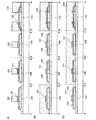
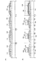
次に、第2の絶縁膜128、第3の導電層138、140、142、144、146を覆うように絶縁膜172を形成する。その後、当該絶縁膜172上に選択的にレジストを形成し、ドライエッチングすることにより第2の導電層127、第3の導電層138が露出するコンタクトホールを形成する。そして、該コンタクトホールを介して、第2の導電層127、第3の導電層138と接する導電層174を形成する(図24、図19参照)。なお、半導体層104、106、108、110にそれぞれ形成された不純物領域125、126、156、162と導電層174とは電気的に接続している。また、導電層174は、ソース配線又はドレイン配線として機能する。
Next, an insulating
絶縁膜172は、CVD法やスパッタ法等により、酸化珪素(SiOx)、窒化珪素(SiNx)、酸化窒化珪素(SiOxNy)(x>y)、窒化酸化珪素(SiNxOy)(x>y)等の酸素または窒素を有する絶縁膜やDLC(ダイヤモンドライクカーボン)等の炭素を含む膜、エポキシ、ポリイミド、ポリアミド、ポリビニルフェノール、ベンゾシクロブテン、アクリル等の有機材料またはシロキサン樹脂等のシロキサン材料からなる単層または積層構造で設けることができる。なお、シロキサン材料とは、Si−O−Si結合を含む材料に相当する。シロキサンは、シリコン(Si)と酸素(O)との結合で骨格構造が構成される。置換基として、少なくとも水素を含む有機基(例えばアルキル基)が用いられる。置換基として、フルオロ基を用いることもできる。または置換基として、少なくとも水素を含む有機基と、フルオロ基とを用いてもよい。
The insulating
導電層174は、CVD法やスパッタリング法等により、アルミニウム(Al)、タングステン(W)、チタン(Ti)、タンタル(Ta)、モリブデン(Mo)、ニッケル(Ni)、白金(Pt)、銅(Cu)、金(Au)、銀(Ag)、マンガン(Mn)、ネオジウム(Nd)、炭素(C)、シリコン(Si)から選択された元素、又はこれらの元素を主成分とする合金材料若しくは化合物材料で、単層又は積層で形成する。アルミニウムを主成分とする合金材料とは、例えば、アルミニウムを主成分としニッケルを含む材料、又は、アルミニウムを主成分とし、ニッケルと、炭素と珪素の一方又は両方とを含む合金材料に相当する。導電層174は、例えば、バリア膜とアルミニウムシリコン(Al−Si)膜とバリア膜の積層構造、バリア膜とアルミニウムシリコン(Al−Si)膜と窒化チタン(TiN)膜とバリア膜の積層構造を採用するとよい。なお、バリア膜とは、チタン、チタンの窒化物、モリブデン、又はモリブデンの窒化物からなる薄膜に相当する。アルミニウムやアルミニウムシリコンは抵抗値が低く、安価であるため、導電層174を形成する材料として最適である。また、上層と下層のバリア層を設けると、アルミニウムやアルミニウムシリコンのヒロックの発生を防止することができる。また、還元性の高い元素であるチタンからなるバリア膜を形成すると、結晶質半導体層上に薄い自然酸化膜ができていたとしても、この自然酸化膜を還元し、結晶質半導体層と良好なコンタクトをとることができる。
The
本実施の形態では、ソース領域又はドレイン領域として機能する不純物領域とソース電極又はドレイン電極として機能する配線との間に第3の導電層が設けられている。よって、第3の導電層上に設けられた絶縁膜をエッチングする際に、半導体層までエッチングされることがなくなり、コンタクト抵抗値の増大を防ぐことができる。よって、低電圧で高効率な書き込みをすることが出来、且つ電荷保持特性のよいメモリを作製することが可能となる。本実施例でしめしたように、メモリ部に加えてロジック部のトランジスタにおいても、本発明の構造を有することにより、さらにコンタクト抵抗値の増大を防ぎ、性能のよい不揮発性半導体記憶装置を作製することができる。本実施例は、本明細書で示した他の実施の形態又は実施例と組み合わせて行うことができる。 In this embodiment, the third conductive layer is provided between the impurity region functioning as the source region or the drain region and the wiring functioning as the source electrode or the drain electrode. Therefore, when the insulating film provided on the third conductive layer is etched, the semiconductor layer is not etched, and an increase in the contact resistance value can be prevented. Therefore, it is possible to manufacture a memory that can perform high-efficiency writing with a low voltage and has good charge retention characteristics. As shown in this embodiment, the transistor of the logic portion as well as the memory portion has the structure of the present invention, so that the contact resistance value is further prevented and a high-performance nonvolatile semiconductor memory device is manufactured. be able to. This example can be implemented in combination with any of the other embodiments or examples shown in this specification.
本実施例では、上記実施例1で示した構造において、一つの島状の半導体層に複数の不揮発性メモリ素子を設けた場合に関して図面を参照して説明する。なお、上記実施例と同じものを指す場合には同様の符号を用いて示し説明を省略する。なお、図25は上面図を示し、図26は図25におけるE−F間、G−H間の断面図を示している。
In this embodiment, a case where a plurality of nonvolatile memory elements are provided in one island-like semiconductor layer in the structure shown in
本実施例で示す不揮発性半導体記憶装置は、ビット線BL0、BL1にそれぞれ電気的に接続された島状の半導体層200a、200bが設けられており、島状の半導体層200a、200bの各々に複数の不揮発性メモリ素子が設けられている(図25、26参照)。具体的には、半導体層200aにおいて、選択トランジスタS01、S02の間に複数の不揮発性メモリ素子M0〜M31を有するNANDセル202aが設けられている。また、半導体層200bにおいても、選択トランジスタの間に複数の不揮発性メモリ素子を有するNANDセル202bが設けられている。また、半導体層200a、200bを分離して設けることによって、隣接するNANDセル202aとNANDセル202bを絶縁分離することが可能となる。
The nonvolatile semiconductor memory device shown in this embodiment includes island-shaped
また、一つの島状の半導体層に複数の不揮発性メモリ素子を設けることによって、より不揮発性メモリ素子の集積化が可能となり、大容量の不揮発性半導体記憶装置を形成することができる。 Further, by providing a plurality of nonvolatile memory elements in one island-like semiconductor layer, the nonvolatile memory elements can be more integrated and a large-capacity nonvolatile semiconductor memory device can be formed.
本実施例は、本明細書で示した他の実施の形態又は実施例と組み合わせて行うことができる。 This example can be implemented in combination with any of the other embodiments or examples shown in this specification.
本実施例では、上述した本発明の不揮発性半導体記憶装置を備えた非接触でデータの入出力が可能である半導体装置の適用例に関して図面を参照して以下に説明する。非接触でデータの入出力が可能である半導体装置は利用の形態によっては、RFIDタグ、IDタグ、ICタグ、ICチップ、RFタグ、無線タグ、電子タグまたは無線チップともよばれる。 In this embodiment, an application example of a semiconductor device including the above-described nonvolatile semiconductor memory device of the present invention and capable of inputting and outputting data without contact will be described with reference to the drawings. A semiconductor device in which data can be input / output without contact is also referred to as an RFID tag, an ID tag, an IC tag, an IC chip, an RF tag, a wireless tag, an electronic tag, or a wireless chip depending on the application.
半導体装置800は、非接触でデータを交信する機能を有し、高周波回路810、電源回路820、リセット回路830、クロック発生回路840、データ復調回路850、データ変調回路860、他の回路の制御を行う制御回路870、記憶回路880およびアンテナ890を有している(図27(A))。高周波回路810はアンテナ890より信号を受信して、データ変調回路860より受信した信号をアンテナ890から出力する回路であり、電源回路820は受信信号から電源電位を生成する回路であり、リセット回路830はリセット信号を生成する回路であり、クロック発生回路840はアンテナ890から入力された受信信号を基に各種クロック信号を生成する回路であり、データ復調回路850は受信信号を復調して制御回路870に出力する回路であり、データ変調回路860は制御回路870から受信した信号を変調する回路である。また、制御回路870としては、例えばコード抽出回路910、コード判定回路920、CRC判定回路930および出力ユニット回路940が設けられている。なお、コード抽出回路910は制御回路870に送られてきた命令に含まれる複数のコードをそれぞれ抽出する回路であり、コード判定回路920は抽出されたコードとリファレンスに相当するコードとを比較して命令の内容を判定する回路であり、CRC判定回路930は判定されたコードに基づいて送信エラー等の有無を検出する回路である。
The semiconductor device 800 has a function of exchanging data without contact, and controls a high frequency circuit 810, a power supply circuit 820, a reset circuit 830, a clock generation circuit 840, a data demodulation circuit 850, a data modulation circuit 860, and other circuits. A control circuit 870, a
次に、上述した半導体装置の動作の一例について説明する。まず、アンテナ890により無線信号が受信される。無線信号は高周波回路810を介して電源回路820に送られ、高電源電位(以下、VDDと記す)が生成される。VDDは半導体装置800が有する各回路に供給される。また、高周波回路810を介してデータ復調回路850に送られた信号は復調される(以下、復調信号)。さらに、高周波回路810を介してリセット回路830およびクロック発生回路840を通った信号及び復調信号は制御回路870に送られる。制御回路870に送られた信号は、コード抽出回路910、コード判定回路920およびCRC判定回路930等によって解析される。そして、解析された信号にしたがって、記憶回路880内に記憶されている半導体装置の情報が出力される。出力された半導体装置の情報は出力ユニット回路940を通って符号化される。さらに、符号化された半導体装置800の情報はデータ変調回路860を通って、アンテナ890により無線信号に載せて送信される。なお、半導体装置800を構成する複数の回路においては、低電源電位(以下、VSS)は共通であり、VSSはGNDとすることができる。また、本発明の不揮発性半導体記憶装置を記憶回路880に適用することができる。本発明の不揮発性半導体記憶装置は、駆動電圧を低くすることができるため、非接触でデータを交信できる距離をのばすことが可能となる。
Next, an example of operation of the above-described semiconductor device will be described. First, a radio signal is received by the antenna 890. The wireless signal is sent to the power supply circuit 820 via the high frequency circuit 810, and a high power supply potential (hereinafter referred to as VDD) is generated. VDD is supplied to each circuit included in the semiconductor device 800. The signal sent to the data demodulation circuit 850 via the high frequency circuit 810 is demodulated (hereinafter, demodulated signal). Further, a signal and a demodulated signal that have passed through the reset circuit 830 and the clock generation circuit 840 via the high frequency circuit 810 are sent to the control circuit 870. The signal sent to the control circuit 870 is analyzed by the code extraction circuit 910, the code determination circuit 920, the CRC determination circuit 930, and the like. Then, information on the semiconductor device stored in the
このように、リーダ/ライタから半導体装置800に信号を送り、当該半導体装置800から送られてきた信号をリーダ/ライタで受信することによって、半導体装置のデータを読み取ることが可能となる。 As described above, by transmitting a signal from the reader / writer to the semiconductor device 800 and receiving the signal transmitted from the semiconductor device 800 by the reader / writer, the data of the semiconductor device can be read.
また、半導体装置800は、各回路への電源電圧の供給を電源(バッテリー)を搭載せず電磁波により行うタイプとしてもよいし、電源(バッテリー)を搭載して電磁波と電源(バッテリー)により各回路に電源電圧を供給するタイプとしてもよい。 Further, the semiconductor device 800 may be of a type in which the power supply voltage is supplied to each circuit by an electromagnetic wave without mounting the power source (battery), or each circuit is mounted by the electromagnetic wave and the power source (battery). It is good also as a type which supplies a power supply voltage to.
次に、非接触でデータの入出力が可能な半導体装置の使用形態の一例について説明する。表示部3210を含む携帯端末の側面には、リーダ/ライタ3200が設けられ、品物3220の側面には半導体装置3230が設けられる(図27(B))。品物3220が含む半導体装置3230にリーダ/ライタ3200をかざすと、表示部3210に品物の原材料や原産地、生産工程ごとの検査結果や流通過程の履歴等、更に商品の説明等の商品に関する情報が表示される。また、商品3260をベルトコンベアにより搬送する際に、リーダ/ライタ3240と、商品3260に設けられた半導体装置3250を用いて、該商品3260の検品を行うことができる(図27(C))。このように、システムに半導体装置を活用することで、情報の取得を簡単に行うことができ、高機能化と高付加価値化を実現する。
Next, an example of a usage pattern of a semiconductor device capable of inputting and outputting data without contact will be described. A reader /
また、本発明の不揮発性半導体記憶装置は、メモリを具備したあらゆる分野の電子機器に用いることが可能である。例えば、本発明の不揮発性半導体記憶装置を適用した電子機器として、ビデオカメラ、デジタルカメラ等のカメラ、ゴーグル型ディスプレイ(ヘッドマウントディスプレイ)、ナビゲーションシステム、音響再生装置(カーオーディオ、オーディオコンポ等)、コンピュータ、ゲーム機器、携帯情報端末(モバイルコンピュータ、携帯電話、携帯型ゲーム機または電子書籍等)、記録媒体を備えた画像再生装置(具体的にはDVD(digital versatile disc)等の記録媒体を再生し、その画像を表示しうるディスプレイを備えた装置)などが挙げられる。それら電子機器の具体例を図28に示す。 In addition, the nonvolatile semiconductor memory device of the present invention can be used for electronic devices in various fields equipped with a memory. For example, as an electronic device to which the nonvolatile semiconductor memory device of the present invention is applied, a camera such as a video camera or a digital camera, a goggle type display (head mounted display), a navigation system, a sound reproduction device (car audio, audio component, etc.), Plays back recording media such as computers, game machines, portable information terminals (mobile computers, mobile phones, portable game machines or electronic books), and image playback devices (specifically DVDs (digital versatile discs)) equipped with recording media And an apparatus provided with a display capable of displaying the image). Specific examples of these electronic devices are shown in FIGS.
図28(A)、(B)は、デジタルカメラを示している。図28(B)は、図28(A)の裏側を示す図である。このデジタルカメラは、筐体2111、表示部2112、レンズ2113、操作キー2114、シャッターボタン2115などを有する。また、取り出し可能な不揮発性のメモリ2116を備えており、当該デジタルカメラで撮影したデータをメモリ2116に記憶させておく構成となっている。本発明を用いて形成された不揮発性の半導体記憶装置は当該メモリ2116に適用することができる。
28A and 28B show a digital camera. FIG. 28B is a diagram showing the back side of FIG. This digital camera includes a
また、図28(C)は、携帯電話を示しており、携帯端末の1つの代表例である。この携帯電話は筐体2121、表示部2122、操作キー2123などを含む。また、携帯電話は、取り出し可能な不揮発性のメモリ2125を備えており、当該携帯電話の電話番号等のデータ、映像、音楽データ等をメモリ2125に記憶させ再生することができる。本発明を用いて形成された不揮発性の半導体記憶装置は当該メモリ2125に適用することができる。
FIG. 28C illustrates a mobile phone, which is a typical example of a mobile terminal. This mobile phone includes a
また、図28(D)は、デジタルプレーヤーを示しており、オーディオ装置の1つの代表例である。図28(D)に示すデジタルプレーヤーは、本体2130、表示部2131、メモリ部2132、操作部2133、イヤホン2134等を含んでいる。なお、イヤホン2134の代わりにヘッドホンや無線式イヤホンを用いることができる。メモリ部2132は、本発明を用いて形成された不揮発性の半導体記憶装置を用いることができる。例えば、記録容量が20ギガバイト以上200ギガバイト(GB)以下のNAND型不揮発性メモリを用い、操作部2133を操作することにより、映像や音声(音楽)を記録、再生することができる。なお、表示部2131は黒色の背景に白色の文字を表示することで消費電力を抑えられる。これは携帯型のオーディオ装置において特に有効である。なお、メモリ部2132に設けられた不揮発性の半導体記憶装置は、取り出し可能な構成としてもよい。
FIG. 28D illustrates a digital player, which is a typical example of an audio device. A digital player shown in FIG. 28D includes a
また、図28(E)は、電子ブック(電子ペーパーともいう)を示している。この電子ブックは、本体2141、表示部2142、操作キー2143、メモリ部2144等を含んでいる。またモデムが本体2141に内蔵されていてもよいし、無線で情報を送受信できる構成としてもよい。メモリ部2144は、本発明を用いて形成された不揮発性の半導体記憶装置を用いることができる。例えば、記録容量が20ギガバイト以上200ギガバイト(GB)以下のNAND型不揮発性メモリを用い、操作キー2143を操作することにより、映像や音声(音楽)を記録、再生することができる。なお、メモリ部2144に設けられた不揮発性の半導体記憶装置は、取り出し可能な構成としてもよい。
FIG. 28E illustrates an electronic book (also referred to as electronic paper). This electronic book includes a
以上の様に、本発明の不揮発性半導体記憶装置の適用範囲は極めて広く、メモリを有するものであればあらゆる分野の電子機器に用いることが可能である。 As described above, the applicable range of the nonvolatile semiconductor memory device of the present invention is so wide that it can be used for electronic devices in various fields as long as it has a memory.
10 基板
12 下地絶縁膜
14 半導体層
16 絶縁膜
20 浮遊ゲート電極
22 絶縁膜
24 制御ゲート電極
26a、26b 導電層
27 絶縁膜
29 チャネル形成領域
10
Claims (6)
前記ソース領域及び前記ドレイン領域の一部と前記チャネル形成領域とを覆う第1の絶縁膜と、
前記第1の絶縁膜上の浮遊ゲート電極と、
前記浮遊ゲート電極を覆う第2の絶縁膜と、
前記第2の絶縁膜上の制御ゲート電極と、
前記ソース領域上の第1の導電層と、
前記ドレイン領域上の第2の導電層と、
前記第2の絶縁膜、前記制御ゲート電極、前記第1の導電層及び前記第2の導電層上の第3の絶縁膜と、
前記第3の絶縁膜に形成されたコンタクトホールを介して前記第1の導電層と接する第3の導電層と、前記第2の導電層と接する第4の導電層と、を有し、
前記ソース領域と前記第3の導電層は、前記第1の導電層を介して電気的に接続され、前記ドレイン領域と前記第4の導電層は、前記第2の導電層を介して電気的に接続され、
前記第1の導電層、前記第2の導電層及び前記制御ゲート電極は、同一の導電層を選択的にエッチングすることにより形成されることを特徴とする不揮発性半導体記憶装置。 A semiconductor layer having a channel formation region, a source region and a drain region;
A first insulating film covering a part of the source region and the drain region and the channel formation region;
A floating gate electrode on the first insulating film;
A second insulating film covering the floating gate electrode;
A control gate electrode on the second insulating film;
A first conductive layer on the source region;
A second conductive layer on the drain region;
A third insulating film on the second insulating film, the control gate electrode, the first conductive layer and the second conductive layer;
A third conductive layer in contact with the first conductive layer through the third contact hole formed in the insulating film, and a fourth conductive layer in contact with the second conductive layer, and
Said third conductive layer and the source region is electrically connected through the first conductive layer, the fourth conductive layer and the drain region is electrically through the second conductive layer Connected to
The non-volatile semiconductor memory device, wherein the first conductive layer, the second conductive layer, and the control gate electrode are formed by selectively etching the same conductive layer.
前記ソース領域及び前記ドレイン領域の一部と前記チャネル形成領域とを覆う第1の絶縁膜と、
前記第1の絶縁膜上の浮遊ゲート電極と、
前記浮遊ゲート電極を覆う第2の絶縁膜と、
前記第2の絶縁膜上の制御ゲート電極と、
前記ソース領域上の第1の導電層と、
前記ドレイン領域上の第2の導電層と、
前記第2の絶縁膜、前記制御ゲート電極、前記第1の導電層及び前記第2の導電層上の第3の絶縁膜と、
前記第3の絶縁膜に形成されたコンタクトホールを介して前記第1の導電層と接する第3の導電層と、前記第2の導電層と接する第4の導電層と、を有し、
前記ソース領域と前記第3の導電層は、前記第1の導電層を介して電気的に接続され、前記ドレイン領域と前記第4の導電層は、前記第2の導電層を介して電気的に接続され、
前記制御ゲート電極は、前記第2の絶縁膜を介して前記浮遊ゲート電極を覆うように形成され、
前記浮遊ゲート電極によって生じた前記制御ゲート電極の段差部分には、サイドウォールが形成され、
前記第1の導電層、前記第2の導電層及び前記制御ゲート電極は、同一の導電層を選択的にエッチングすることにより形成されることを特徴とする不揮発性半導体記憶装置。 A semiconductor layer having a channel formation region, a source region and a drain region;
A first insulating film covering a part of the source region and the drain region and the channel formation region;
A floating gate electrode on the first insulating film;
A second insulating film covering the floating gate electrode;
A control gate electrode on the second insulating film;
A first conductive layer on the source region;
A second conductive layer on the drain region;
A third insulating film on the second insulating film, the control gate electrode, the first conductive layer and the second conductive layer;
A third conductive layer in contact with the first conductive layer through the third contact hole formed in the insulating film, and a fourth conductive layer in contact with the second conductive layer, and
Said third conductive layer and the source region is electrically connected through the first conductive layer, the fourth conductive layer and the drain region is electrically through the second conductive layer Connected to
The control gate electrode is formed so as to cover the floating gate electrode through the second insulating film,
A side wall is formed in the step portion of the control gate electrode generated by the floating gate electrode,
The non-volatile semiconductor memory device, wherein the first conductive layer, the second conductive layer, and the control gate electrode are formed by selectively etching the same conductive layer.
前記浮遊ゲート電極は、第1の浮遊ゲート電極及び第2の浮遊ゲート電極の積層構造を有することを特徴とする不揮発性半導体記憶装置。 In claim 1 or claim 2,
The non-volatile semiconductor memory device, wherein the floating gate electrode has a stacked structure of a first floating gate electrode and a second floating gate electrode.
前記第1の浮遊ゲート電極は前記第1の絶縁膜側に設けられ、前記第1の浮遊ゲート電極上に第1の浮遊ゲート電極よりも幅が短い前記第2の浮遊ゲート電極が設けられることを特徴とする不揮発性半導体記憶装置。 In claim 3 ,
The first floating gate electrode is provided on the first insulating film side, and the second floating gate electrode having a shorter width than the first floating gate electrode is provided on the first floating gate electrode. A non-volatile semiconductor memory device.
前記第1の絶縁膜上に浮遊ゲート電極を形成し、
前記浮遊ゲート電極をマスクとして前記半導体層に不純物元素を導入してソース領域及びドレイン領域を形成し、
前記浮遊ゲート電極を覆って第2の絶縁膜を形成し、
前記第1の絶縁膜と前記第2の絶縁膜の一部をエッチングして、前記ソース領域及び前記ドレイン領域の一部を露出させ、
前記第2の絶縁膜、前記露出した前記ソース領域及び前記ドレイン領域上に第1の導電層を形成し、
前記第1の導電層をエッチングして、前記第2の絶縁膜上に制御ゲート電極を形成し、
前記露出した前記ソース領域上に第2の導電層及び前記露出した前記ドレイン領域上に第3の導電層を形成し、
前記第2の絶縁膜、前記制御ゲート電極、前記第2の導電層及び前記第3の導電層上に第3の絶縁膜を形成し、
前記第3の絶縁膜に、前記第2の導電層及び前記第3の導電層の一部が露出するコンタクトホールを開口し、
前記露出した前記第2の導電層上に、ソース電極を形成し、前記露出した前記第3の導電層上にドレイン電極を形成することを特徴とする不揮発性半導体記憶装置の作製方法。 Forming a first insulating film on the semiconductor layer;
Forming a floating gate electrode on the first insulating film;
An impurity element is introduced into the semiconductor layer using the floating gate electrode as a mask to form a source region and a drain region,
Forming a second insulating film covering the floating gate electrode;
Etching a part of the first insulating film and the second insulating film to expose a part of the source region and the drain region,
Forming a first conductive layer on the second insulating film, the exposed source region and the drain region;
Etching the first conductive layer to form a control gate electrode on the second insulating film;
Forming a second conductive layer on the exposed source region and a third conductive layer on the exposed drain region;
Forming a third insulating film on the second insulating film, the control gate electrode, the second conductive layer, and the third conductive layer;
Opening a contact hole in the third insulating film through which the second conductive layer and a part of the third conductive layer are exposed;
A method for manufacturing a nonvolatile semiconductor memory device, comprising: forming a source electrode on the exposed second conductive layer; and forming a drain electrode on the exposed third conductive layer.
前記第1の絶縁膜上に浮遊ゲート電極を形成し、
前記浮遊ゲート電極をマスクとして前記半導体層に不純物元素を導入してソース領域及びドレイン領域を形成し、
前記浮遊ゲート電極を覆って第2の絶縁膜を形成し、
前記第1の絶縁膜と前記第2の絶縁膜の一部をエッチングして、前記ソース領域及び前記ドレイン領域の一部を露出させ、
前記第2の絶縁膜、前記露出した前記ソース領域及び前記ドレイン領域上に第1の導電層を形成し、
前記第1の導電層上に第3の絶縁膜を形成し、
前記第3の絶縁膜をエッチングして前記浮遊ゲート電極によって生じた段差部分にサイドウォールを形成し、
前記第1の導電層をエッチングして、前記第2の絶縁膜上に制御ゲート電極を形成し、
前記露出した前記ソース領域上に第2の導電層及び前記露出した前記ドレイン領域上に第3の導電層を形成し、
前記第2の絶縁膜、前記制御ゲート電極、前記第2の導電層及び前記第3の導電層上に第4の絶縁膜を形成し、
前記第4の絶縁膜に、前記第2の導電層及び前記第3の導電層の一部が露出するコンタクトホールを開口し、
前記露出した前記第2の導電層上に、ソース電極を形成し、前記露出した前記第3の導電層上にドレイン電極を形成することを特徴とする不揮発性半導体記憶装置の作製方法。 Forming a first insulating film on the semiconductor layer;
Forming a floating gate electrode on the first insulating film;
An impurity element is introduced into the semiconductor layer using the floating gate electrode as a mask to form a source region and a drain region,
Forming a second insulating film covering the floating gate electrode;
Etching a part of the first insulating film and the second insulating film to expose a part of the source region and the drain region,
Forming a first conductive layer on the second insulating film, the exposed source region and the drain region;
Forming a third insulating film on the first conductive layer;
Etching the third insulating film to form a side wall at the step formed by the floating gate electrode,
Etching the first conductive layer to form a control gate electrode on the second insulating film;
Forming a second conductive layer on the exposed source region and a third conductive layer on the exposed drain region;
Forming a fourth insulating film on the second insulating film, the control gate electrode, the second conductive layer, and the third conductive layer;
Opening a contact hole in the fourth insulating film through which a part of the second conductive layer and the third conductive layer is exposed;
A method for manufacturing a nonvolatile semiconductor memory device, comprising: forming a source electrode on the exposed second conductive layer; and forming a drain electrode on the exposed third conductive layer.
Priority Applications (1)
| Application Number | Priority Date | Filing Date | Title |
|---|---|---|---|
| JP2007076018A JP5132171B2 (en) | 2006-03-31 | 2007-03-23 | Nonvolatile semiconductor memory device and manufacturing method thereof, and semiconductor device and manufacturing method thereof |
Applications Claiming Priority (3)
| Application Number | Priority Date | Filing Date | Title |
|---|---|---|---|
| JP2006101254 | 2006-03-31 | ||
| JP2006101254 | 2006-03-31 | ||
| JP2007076018A JP5132171B2 (en) | 2006-03-31 | 2007-03-23 | Nonvolatile semiconductor memory device and manufacturing method thereof, and semiconductor device and manufacturing method thereof |
Related Child Applications (1)
| Application Number | Title | Priority Date | Filing Date |
|---|---|---|---|
| JP2012223251A Division JP5604492B2 (en) | 2006-03-31 | 2012-10-05 | Semiconductor device |
Publications (3)
| Publication Number | Publication Date |
|---|---|
| JP2007294915A JP2007294915A (en) | 2007-11-08 |
| JP2007294915A5 JP2007294915A5 (en) | 2010-04-30 |
| JP5132171B2 true JP5132171B2 (en) | 2013-01-30 |
Family
ID=38765167
Family Applications (1)
| Application Number | Title | Priority Date | Filing Date |
|---|---|---|---|
| JP2007076018A Expired - Fee Related JP5132171B2 (en) | 2006-03-31 | 2007-03-23 | Nonvolatile semiconductor memory device and manufacturing method thereof, and semiconductor device and manufacturing method thereof |
Country Status (1)
| Country | Link |
|---|---|
| JP (1) | JP5132171B2 (en) |
Families Citing this family (2)
| Publication number | Priority date | Publication date | Assignee | Title |
|---|---|---|---|---|
| US8441009B2 (en) * | 2009-12-25 | 2013-05-14 | Semiconductor Energy Laboratory Co., Ltd. | Semiconductor device and manufacturing method thereof |
| JP2015043388A (en) * | 2013-08-26 | 2015-03-05 | 国立大学法人 琉球大学 | Semiconductor device, method of manufacturing semiconductor device, and electronic apparatus |
Family Cites Families (3)
| Publication number | Priority date | Publication date | Assignee | Title |
|---|---|---|---|---|
| JP3980178B2 (en) * | 1997-08-29 | 2007-09-26 | 株式会社半導体エネルギー研究所 | Nonvolatile memory and semiconductor device |
| JP2001326289A (en) * | 2000-03-08 | 2001-11-22 | Semiconductor Energy Lab Co Ltd | Nonvolatile memory and semiconductor device |
| US7378286B2 (en) * | 2004-08-20 | 2008-05-27 | Sharp Laboratories Of America, Inc. | Semiconductive metal oxide thin film ferroelectric memory transistor |
-
2007
- 2007-03-23 JP JP2007076018A patent/JP5132171B2/en not_active Expired - Fee Related
Also Published As
| Publication number | Publication date |
|---|---|
| JP2007294915A (en) | 2007-11-08 |
Similar Documents
| Publication | Publication Date | Title |
|---|---|---|
| JP5604492B2 (en) | Semiconductor device | |
| KR101349879B1 (en) | Nonvolatile semiconductor memory device | |
| KR101406766B1 (en) | Nonvolatile semiconductor memory device and manufacturing method thereof | |
| US7709883B2 (en) | Nonvolatile semiconductor memory device | |
| KR101345418B1 (en) | Nonvolatile semiconductor memory device | |
| KR101324757B1 (en) | Nonvolatile semiconductor memory device | |
| JP2012212892A (en) | Method for erasing data of nand type nonvolatile memory | |
| EP1837900A2 (en) | Nonvolatile semiconductor memory device | |
| JP5483660B2 (en) | Semiconductor device | |
| JP5238178B2 (en) | Semiconductor device | |
| JP2007294082A (en) | Method for deleting data from nand type nonvolatile memory | |
| US8895388B2 (en) | Method of manufacturing a semiconductor device and a non-volatile semiconductor storage device including the formation of an insulating layer using a plasma treatment | |
| JP5094179B2 (en) | Nonvolatile semiconductor memory device | |
| JP5164404B2 (en) | Nonvolatile semiconductor memory device | |
| JP5132171B2 (en) | Nonvolatile semiconductor memory device and manufacturing method thereof, and semiconductor device and manufacturing method thereof | |
| JP5183946B2 (en) | Nonvolatile semiconductor memory device | |
| JP5164405B2 (en) | Nonvolatile semiconductor memory device | |
| JP2008047884A (en) | Manufacturing method for semiconductor device, and manufacturing method for nonvolatile semiconductor memory device | |
| JP5466815B2 (en) | Semiconductor device | |
| JP5483659B2 (en) | Semiconductor device |
Legal Events
| Date | Code | Title | Description |
|---|---|---|---|
| A521 | Request for written amendment filed |
Free format text: JAPANESE INTERMEDIATE CODE: A523 Effective date: 20100312 |
|
| A621 | Written request for application examination |
Free format text: JAPANESE INTERMEDIATE CODE: A621 Effective date: 20100312 |
|
| A977 | Report on retrieval |
Free format text: JAPANESE INTERMEDIATE CODE: A971007 Effective date: 20120830 |
|
| A131 | Notification of reasons for refusal |
Free format text: JAPANESE INTERMEDIATE CODE: A131 Effective date: 20120904 |
|
| A521 | Request for written amendment filed |
Free format text: JAPANESE INTERMEDIATE CODE: A523 Effective date: 20121005 |
|
| TRDD | Decision of grant or rejection written | ||
| A01 | Written decision to grant a patent or to grant a registration (utility model) |
Free format text: JAPANESE INTERMEDIATE CODE: A01 Effective date: 20121030 |
|
| A01 | Written decision to grant a patent or to grant a registration (utility model) |
Free format text: JAPANESE INTERMEDIATE CODE: A01 |
|
| A61 | First payment of annual fees (during grant procedure) |
Free format text: JAPANESE INTERMEDIATE CODE: A61 Effective date: 20121106 |
|
| FPAY | Renewal fee payment (event date is renewal date of database) |
Free format text: PAYMENT UNTIL: 20151116 Year of fee payment: 3 |
|
| R150 | Certificate of patent or registration of utility model |
Free format text: JAPANESE INTERMEDIATE CODE: R150 Ref document number: 5132171 Country of ref document: JP Free format text: JAPANESE INTERMEDIATE CODE: R150 |
|
| R250 | Receipt of annual fees |
Free format text: JAPANESE INTERMEDIATE CODE: R250 |
|
| R250 | Receipt of annual fees |
Free format text: JAPANESE INTERMEDIATE CODE: R250 |
|
| R250 | Receipt of annual fees |
Free format text: JAPANESE INTERMEDIATE CODE: R250 |
|
| R250 | Receipt of annual fees |
Free format text: JAPANESE INTERMEDIATE CODE: R250 |
|
| R250 | Receipt of annual fees |
Free format text: JAPANESE INTERMEDIATE CODE: R250 |
|
| R250 | Receipt of annual fees |
Free format text: JAPANESE INTERMEDIATE CODE: R250 |
|
| LAPS | Cancellation because of no payment of annual fees |