JP5129989B2 - Conference layout control and control protocol - Google Patents
Conference layout control and control protocol Download PDFInfo
- Publication number
- JP5129989B2 JP5129989B2 JP2007156978A JP2007156978A JP5129989B2 JP 5129989 B2 JP5129989 B2 JP 5129989B2 JP 2007156978 A JP2007156978 A JP 2007156978A JP 2007156978 A JP2007156978 A JP 2007156978A JP 5129989 B2 JP5129989 B2 JP 5129989B2
- Authority
- JP
- Japan
- Prior art keywords
- call
- videophone
- conference
- video
- node
- Prior art date
- Legal status (The legal status is an assumption and is not a legal conclusion. Google has not performed a legal analysis and makes no representation as to the accuracy of the status listed.)
- Expired - Fee Related
Links
Images


Classifications
-
- H—ELECTRICITY
- H04—ELECTRIC COMMUNICATION TECHNIQUE
- H04N—PICTORIAL COMMUNICATION, e.g. TELEVISION
- H04N7/00—Television systems
- H04N7/14—Systems for two-way working
- H04N7/141—Systems for two-way working between two video terminals, e.g. videophone
- H04N7/147—Communication arrangements, e.g. identifying the communication as a video-communication, intermediate storage of the signals
-
- H—ELECTRICITY
- H04—ELECTRIC COMMUNICATION TECHNIQUE
- H04L—TRANSMISSION OF DIGITAL INFORMATION, e.g. TELEGRAPHIC COMMUNICATION
- H04L65/00—Network arrangements, protocols or services for supporting real-time applications in data packet communication
- H04L65/1066—Session management
- H04L65/1101—Session protocols
- H04L65/1104—Session initiation protocol [SIP]
-
- H—ELECTRICITY
- H04—ELECTRIC COMMUNICATION TECHNIQUE
- H04L—TRANSMISSION OF DIGITAL INFORMATION, e.g. TELEGRAPHIC COMMUNICATION
- H04L65/00—Network arrangements, protocols or services for supporting real-time applications in data packet communication
- H04L65/40—Support for services or applications
- H04L65/403—Arrangements for multi-party communication, e.g. for conferences
- H04L65/4038—Arrangements for multi-party communication, e.g. for conferences with floor control
-
- H—ELECTRICITY
- H04—ELECTRIC COMMUNICATION TECHNIQUE
- H04N—PICTORIAL COMMUNICATION, e.g. TELEVISION
- H04N19/00—Methods or arrangements for coding, decoding, compressing or decompressing digital video signals
- H04N19/10—Methods or arrangements for coding, decoding, compressing or decompressing digital video signals using adaptive coding
- H04N19/102—Methods or arrangements for coding, decoding, compressing or decompressing digital video signals using adaptive coding characterised by the element, parameter or selection affected or controlled by the adaptive coding
- H04N19/103—Selection of coding mode or of prediction mode
- H04N19/114—Adapting the group of pictures [GOP] structure, e.g. number of B-frames between two anchor frames
-
- H—ELECTRICITY
- H04—ELECTRIC COMMUNICATION TECHNIQUE
- H04N—PICTORIAL COMMUNICATION, e.g. TELEVISION
- H04N19/00—Methods or arrangements for coding, decoding, compressing or decompressing digital video signals
- H04N19/60—Methods or arrangements for coding, decoding, compressing or decompressing digital video signals using transform coding
- H04N19/61—Methods or arrangements for coding, decoding, compressing or decompressing digital video signals using transform coding in combination with predictive coding
-
- H—ELECTRICITY
- H04—ELECTRIC COMMUNICATION TECHNIQUE
- H04N—PICTORIAL COMMUNICATION, e.g. TELEVISION
- H04N7/00—Television systems
- H04N7/14—Systems for two-way working
- H04N7/141—Systems for two-way working between two video terminals, e.g. videophone
- H04N7/148—Interfacing a video terminal to a particular transmission medium, e.g. ISDN
-
- H—ELECTRICITY
- H04—ELECTRIC COMMUNICATION TECHNIQUE
- H04N—PICTORIAL COMMUNICATION, e.g. TELEVISION
- H04N7/00—Television systems
- H04N7/14—Systems for two-way working
- H04N7/15—Conference systems
- H04N7/152—Multipoint control units therefor
Description
関連出願の表示:本願は、Richard E. Huber、Arun Punj及びPeter D. Hillによる米国仮特許出願第60/814,477号「インテリジェントオーディオ制限方法(Intelligent Audio Limit Method)」(代理人管理番号:Fore-119)、Arun Punj、Richard E. Huber及びGregory H. Smithによる米国仮特許出願第60/814,491号「独立したマルチメディアソースの会議コールへの結び付け(Associating Independent Multimedia Sources Into a Conference Call)」(代理人管理番号:Fore-121)という、同時に出願された2つの米国仮特許出願に関係しており、これらの仮特許出願は、引用を以て本件明細書の一部となる。 Related Application Indication: This application is a US Provisional Patent Application No. 60 / 814,477 “Intelligent Audio Limit Method” by Richard E. Huber, Arun Punj and Peter D. Hill (agent control number: Fore-119), Arun Punj, Richard E. Huber and Gregory H. Smith, US Provisional Patent Application No. 60 / 814,491 “Associating Independent Multimedia Sources Into a Conference Call. ) "(Agent control number: Fore-121), which relates to two US provisional patent applications filed at the same time, which are hereby incorporated by reference.
本発明は、電話会議(teleconference)のビデオディスプレイに関する。より詳細には、本発明は、電話会議のビデオディスプレイの制御に関しており、電話会議のノードの少なくとも1つが、各ノードに固有であり得る特定のフォーマットで、会議の各ノードのディスプレイレイアウトを少なくとも部分的に個々に制御する。 The present invention relates to a video display for teleconference. More particularly, the present invention relates to control of video conferencing video displays, wherein at least one of the conferencing nodes' display layout is in a specific format where at least one of the conferencing nodes may be specific to each node. Control individually.
本発明は、ノード間における電話会議に関しており、各ノードは、会議の変化が起こると、その他のノードに会議の変化のみを知らせる。より詳細には、本発明は、ノード間における電話会議に関しており、各ノードは、会議の変化が起こると、変化により影響を受けるノードのみに会議の変化のみを知らせる。 The present invention relates to a conference call between nodes, and each node informs other nodes only of the conference change when the conference change occurs. More specifically, the present invention relates to a conference call between nodes, and when a conference change occurs, each node informs only the node affected by the change of the conference only.
ディスプレイレイアウトに関して、標準的なMCUベースの会議コールでは、MCUは、各参加者のビデオストリームのレイアウトを制御する。実際に、MCUは、全ての参加者に同じ画像を送る。例えば、10人の参加者がいる会議コールでは、MCUは、B、C、D及びEと呼ぶことにする任意の4人を選択して、B、C、D及びEの合成画像を(多分ハリウッドスクエアのように)作成し、それを全ての参加者に送る。 With respect to display layout, in a standard MCU-based conference call, the MCU controls the layout of each participant's video stream. In fact, the MCU sends the same image to all participants. For example, in a conference call with 10 participants, the MCU selects any four people who will be referred to as B, C, D, and E, and creates a composite image of B, C, D, and E (maybe Create (like Hollywood Square) and send it to all participants.
ViPrにおいて、このモデルは、各参加者が独立して、個々にレイアウトを選択できるように拡張されている。故に、Aは、大きなビデオで2人(B及びC)を、小さなビデオで他の7人を見ることができた。Bは、大きなビデオの1人と、小さなビデオの3人と、1つのTVチャンネルを、そのディスプレイで選択できた。 In ViPr, this model is extended so that each participant can independently select a layout. So A could see two people (B and C) in the big video and the other seven in the small video. B could select one large video, three small videos, and one TV channel on the display.
プロトコルに関して、10人の参加者がいる会議コールを考える。従来のシグナリングプロトコルでは、会議の状態に変化があると、例えば、P1がそのビデオを無効にすると、メッセージが使用されて、そのメッセージは、P1乃至P10の全ての参加者に情報と共に送られる。これは、深刻なスケーラビリティの問題を引き起こす。本発明は、効率的な方法で、非常に大規模な会議コール(数百人の参加者)を制御する技術を与える。その技術によれば、送信される必要があるのは差異だけとなり、例えば、上記の例では、小さいNOTIFYイベントが、P1がその送信器を切ったという情報と共に送られる。 Consider a conference call with 10 participants in terms of protocol. In conventional signaling protocols, if there is a change in the state of the conference, for example, if P1 disables the video, a message is used and the message is sent along with the information to all participants in P1 through P10. This causes serious scalability problems. The present invention provides a technique for controlling very large conference calls (hundreds of participants) in an efficient manner. According to that technique, only the difference needs to be transmitted, for example, in the above example, a small NOTIFY event is sent with information that P1 has disconnected its transmitter.
本発明は、電話会議システムに関する。システムはネットワークを備える。システムは、互いに通信して電話会議を構成する複数のノードを備えており、各ノードのライブシーンで電話会議が構成されるのが好ましい。各ノードは、ディスプレイレイアウトを有するビデオディスプレイを有しており、少なくとも1つのノードは、各ノードに固有であり得る特定のフォーマットで、会議の各ノードのディスプレイレイアウトを少なくとも部分的に個々に制御する。 The present invention relates to a telephone conference system. The system comprises a network. The system preferably includes a plurality of nodes that communicate with each other to form a conference call, and the conference call is preferably configured in a live scene of each node. Each node has a video display with a display layout, and at least one node individually controls the display layout of each node in the conference in a specific format that may be specific to each node. .
本発明は、電話会議を提供する方法に関する。この方法は、ネットワークを通じて互いに通信する複数のノードで会議を構成するステップを含んでおり、各ノードのライブシーンで会議が構成されるのが好ましい。各ノードは、ディスプレイレイアウトを有するビデオディスプレイを有している。少なくとも1つのノードを用いて、各ノードに固有であり得る特定のフォーマットで、会議の各ノードのディスプレイレイアウトを少なくとも部分的に個々に制御するステップがある。 The present invention relates to a method for providing a conference call. The method includes the step of configuring a conference with a plurality of nodes communicating with each other through a network, and preferably the conference is configured with a live scene of each node. Each node has a video display having a display layout. There is the step of at least partially individually controlling the display layout of each node of the conference in a specific format that may be specific to each node using at least one node.
本発明は、ネットワーク用の電話会議用ノードに関しており、ネットワークは、その他のノードを伴っている。電話会議用ノードは、ネットワークを通じて互いに通信して会議を構成する複数のノードと通信するネットワークインターフェイスを備えており、各ノードのライブシーンで電話会議が構成されるのが好ましい。電話会議用ノードは、各ノードに固有であり得る特定のフォーマットで、会議の各ノードのディスプレイレイアウトを少なくとも部分的に個々に制御するコントローラを備えている。 The present invention relates to a teleconferencing node for a network, the network being accompanied by other nodes. The teleconference node preferably includes a network interface that communicates with each other through a network to communicate with a plurality of nodes that form the conference, and the teleconference is preferably configured in a live scene of each node. The teleconferencing node comprises a controller that at least partially individually controls the display layout of each node of the conference in a specific format that may be specific to each node.
本発明は、電話会議システムに関する。システムは、ネットワークを備えている。システムは、ネットワークを通じて互いに通信して会議を構成する複数のノードを備えており、各ノードのライブシーンで会議が構成されるのが好ましい。各ノードは、変化が起こると、その他のノードに変化のみを伝える。 The present invention relates to a telephone conference system. The system includes a network. The system preferably includes a plurality of nodes that communicate with each other through a network to form a conference, and the conference is preferably configured with a live scene of each node. Each node communicates only the change to the other nodes when a change occurs.
本発明は、少なくとも3つのノード、例えばパーティの間で、電気通信会議を開催する方法に関する。その方法は、ノード間の会議を確立するステップを含んでおり、各ノードのライブシーンで会議が確立されるのが好ましい。会議に変化を起こすステップがある。変化のみをノードに送信するステップがあり、各ノードのライブシーンの変化を伝えるのが好ましい。 The present invention relates to a method for holding a telecommunications conference between at least three nodes, for example parties. The method includes establishing a conference between the nodes, preferably the conference is established in the live scene of each node. There are steps to change the meeting. There is a step of sending only changes to the nodes, preferably conveying the changes in each node's live scene.
本発明は、ネットワーク用の電話会議用ノードに関しており、ネットワークは、その他のノードを伴っている。電話会議用ノードは、互いに通信して会議を構成する複数のノードと通信するネットワークインターフェイスを備えており、各ノードのライブシーンで会議が構成されるのが好ましい。電話会議用ノードは、変化が起こるとその変化のみをその他のノードに送信するコントローラを備えている。 The present invention relates to a teleconferencing node for a network, the network being accompanied by other nodes. The teleconference node preferably includes a network interface that communicates with a plurality of nodes that communicate with each other to form a conference, and the conference is preferably configured with a live scene of each node. When a change occurs, the conference call node includes a controller that transmits only the change to the other nodes.
多数の会議参加者を効率的に制御する機能は、非常に望ましいものである。これは、特に、低帯域幅のリンクについて正しい。さらに、これは、交換される必要があるメッセージが非常に小さいので、中間ノードの処理を低減する。 The ability to efficiently control a large number of conference participants is highly desirable. This is especially true for low bandwidth links. Furthermore, this reduces the processing of intermediate nodes since the messages that need to be exchanged are very small.
添付の図面を参照すると、幾つかの図面を通して、同じ参照符号が類似又は同様な部分を指している。特に図20及び図21を参照すると、電話会議システム(10)が示されている。システム(10)は、ネットワーク(40)を備えている。システム(10)は、互いに通信して、会議を構成する複数のノードを備えており、各ノードのライブシーンで電話会議が構成されるのが好ましい。各ノードは、ディスプレイレイアウトを有するビデオディスプレイ(54)を有しており、少なくとも1つのノードは、各ノードに固有であり得る特定のフォーマットで、会議の各ノードのディスプレイレイアウトを少なくとも部分的に個々に制御する。
Referring to the accompanying drawings, like reference numerals designate similar or similar parts throughout the several views. With particular reference to FIGS. 20 and 21, a
各ノードは、特定のフォーマットでビデオを強制的に表示させられるのが好ましい。各ノードは、特定のフォーマットに固定されるのが好ましい。各ノードは、ディスプレイの特定の場所にて、会議のその他のノードから送られた幾つかのビデオストリームを強制的に表示させられるのが好ましい。各ノードは、複数のノードの1つによって制御されないスクリ−ンの任意の部分で表示されるものを制御するのが好ましい。複数のノードの1つは、各ノードのディスプレイレイアウトを完全に制御するのが好ましい。 Each node is preferably forced to display the video in a particular format. Each node is preferably fixed in a specific format. Each node is preferably forced to display several video streams sent from other nodes in the conference at a particular location on the display. Each node preferably controls what is displayed on any part of the screen that is not controlled by one of the plurality of nodes. One of the plurality of nodes preferably fully controls the display layout of each node.
本発明は、電話会議を提供する方法に関する。この方法は、ネットワーク(40)を通じて互いに通信する複数のノードで会議を構成するステップを含んでおり、各ノードのライブシーンで会議が構成されるのが好ましい。各ノードは、ディスプレイレイアウトを有するビデオディスプレイ(54)を有している。少なくとも1つのノードを用いて、各ノードに固有であり得る特定のフォーマットで、会議の各ノードのディスプレイレイアウトを少なくとも部分的に個々に制御するステップがある。 The present invention relates to a method for providing a conference call. This method includes the step of composing a conference with a plurality of nodes communicating with each other through the network (40), and the conference is preferably composed of a live scene of each node. Each node has a video display (54) having a display layout. There is the step of at least partially individually controlling the display layout of each node of the conference in a specific format that may be specific to each node using at least one node.
本発明は、ネットワーク(40)用の電話会議用ノードに関しており、ネットワーク(40)は、その他のノードを伴っている。電話会議用ノードは、複数のノードと通信して、ライブ会議を構成するネットワークインターフェイス(42)を備えており、各ノードのライブシーンでライブ会議が構成されるのが好ましい。電話会議用ノードは、各ノードに固有であり得る特定のフォーマットで、会議の各ノードのディスプレイレイアウトを少なくとも部分的に個々に制御するコントローラ(19)を備えている。 The present invention relates to a conference call node for the network (40), and the network (40) is accompanied by other nodes. The teleconference node preferably includes a network interface (42) that communicates with a plurality of nodes to form a live conference, and the live conference is preferably configured with a live scene of each node. The conference call node comprises a controller (19) that at least partially individually controls the display layout of each node of the conference in a specific format that may be specific to each node.
本発明の動作において、本発明は、会議参加者の1人から送られる会議参加者個別の画面のレイアウトを制御する技術を与える。例えば、P1からP10までの会議コールの参加者がいて、それら参加者の1人がモデレータ(moderator)となり、P2に対して、各参加者の参加者の夫々のライブシーンを、P1及びP5を大きいビデオで、残りを小さいビデオで強制的に見させることができるだろう。各パーティのディスプレイは、このような方法で個別に制御されるだろう。 In the operation of the present invention, the present invention provides a technique for controlling the layout of an individual screen of a conference participant sent from one conference participant. For example, there are participants in a conference call from P1 to P10, and one of those participants becomes a moderator. A large video could force the rest to be seen in a small video. Each party's display will be controlled individually in this way.
このレイアウト制御は、スクリーン全体ではなく個々のウインドウに実行されて、スクリーン上の管理外の(non-managed)ウインドウにも個別に制御が提供されてもよい。 This layout control may be performed on individual windows rather than the entire screen, and individual controls may be provided for non-managed windows on the screen.
遠隔のパーティが、各会議参加者のスクリーンレイアウトを制御できる。通常は、モデレータが、全てのパーティに対してモデレータと同じレイアウトを使用するように強制するだろう。しかしながら、細かい(fine grain)制御によって、会議参加者のサブセッションに渡ってサブモデレータの制御が認められるケースもあり得るだろう。 A remote party can control the screen layout of each conference participant. Normally, the moderator will force all parties to use the same layout as the moderator. However, there may be cases where fine mode control allows control of the sub-moderator across conference session sub-sessions.
レイアウト制御機構は、会議参加者の所望のスクリーンレイアウトを含むレイアウトメッセージを生成する。レイアウトメッセージはまた、このメッセージを受信すべき参加者のリストを含む。そして、このレイアウトメッセージは、SIP NOTIFYイベントを介して、会議フォーカス又はホストに送られる。会議フォーカスは、このメッセージを、このリストに含まれる各パーティの出力メッセージキューに加える。会議フォーカスは、各パーティについてキューに入れられたイベントの全てを処理する際に、このメッセージを送る。メッセージが特定のパーティに送られて受信されると、そのパーティは、メッセージに含まれるリクエストに合うように、自己のスクリーンレイアウトを変更する。スクリーンレイアウトの変更が、新しいメディアストリームへのパーティの接続又は接続解除を要求する場合、パーティは、適当なイベントを発行して、リクエストされた変更を行うだろう。 The layout control mechanism generates a layout message that includes the desired screen layout of the conference participants. The layout message also includes a list of participants that should receive this message. This layout message is then sent to the conference focus or host via a SIP NOTIFY event. The conference focus adds this message to the output message queue of each party included in this list. The conference focus sends this message as it processes all of the queued events for each party. When a message is sent to and received by a particular party, that party changes its screen layout to suit the request contained in the message. If a screen layout change requires a party to connect or disconnect from a new media stream, the party will issue the appropriate event to make the requested change.
本発明では、ユーザ又は1組のユーザ(1又は複数のモデレータ)に、会議の各ViPrビデオフォンのディスプレイレイアウトを個々に制御することが可能な機能が与えられている。この制御は、部分的又は全体的であってよい。全体的な制御のディスプレイレイアウトフォーマットでは、会議の各参加者は、特定のフォーマットで画像を表示するように強制される。それは、MCUに幾らか似ているが、各参加者を夫々異なるフォーマットに固定できる点で異なっている。しかし、参加者が、あるフォーマットに一旦固定されると、それは、会議コールのディスプレイレイアウトを制御することはできない。例えば、Aは、C、D及びEから送られたライブシーンを3つの大きなビデオで表示し、F、G、H、I、J及びKを6つの小さなビデオで表示するように固定され得る。 In the present invention, a user or a set of users (one or more moderators) is provided with the ability to individually control the display layout of each ViPr videophone in a conference. This control may be partial or total. In the overall control display layout format, each participant in the conference is forced to display the image in a specific format. It is somewhat similar to an MCU, but differs in that each participant can be fixed in a different format. However, once a participant is fixed in a certain format, it cannot control the display layout of the conference call. For example, A can be fixed to display live scenes sent from C, D, and E in three large videos and F, G, H, I, J, and K in six small videos.
部分的な制御のディスプレイフォーマットでは、各参加者は、特定の場所に幾つかのストリームを表示するように指示される。しかし、それは、スクリーンの残りに表示されるものを制御する。例えば、Aは、左の大きなビデオでBを表示するように指示され得る。しかしながら、それは、1つ、2つ、又は3つの大きなビデオを表示することを選択可能である。同様に、このスキームは、音声又は小さいビデオに使用できるだろう。 In the partially controlled display format, each participant is instructed to display several streams at a particular location. However, it controls what is displayed on the rest of the screen. For example, A may be instructed to display B in the left large video. However, it can choose to display one, two, or three large videos. Similarly, this scheme could be used for audio or small video.
Layout Controlメッセージは、SIP/NOTIFYメッセージとして送られるが、それらは、その他のSIP又はHTTP手段を介して送られてもよい。 Although Layout Control messages are sent as SIP / NOTIFY messages, they may be sent via other SIP or HTTP means.
「典型的な」ViPr会議コールでは、各端末に、会議コールにおけるその他の参加者の各々から送られる利用可能なオーディオ及びビデオスストリームの全てが与えられる。各端末の各ユーザは、通常、自己のローカルな端末に、スクリーンに自動的に各ビデオを順番に配置させるだろう。そして、ユーザは、どのパーティのビデオが、大きなビデオウインドウとして、又は小さなビデオウインドウとしてスクリーン上に示されるかを手動で選択できるだろう。 In a “typical” ViPr conference call, each terminal is given all of the available audio and video streams sent from each of the other participants in the conference call. Each user at each terminal will typically have their local terminal automatically place each video on the screen in turn. The user will then be able to manually select which party's video is shown on the screen as a large video window or as a small video window.
コールの参加者が、コールを管理すること(moderate)を希望する場合、彼らは、「Layout Control」の特徴を用いて、その他の端末の幾つか又は全てを制限する。これらの制限は、どの参加者が、大きなビデオウインドウとして表示されるかを含むことができる。それらはまた、小さなビデオウインドウのどれが、特定の参加者に固定されるかを制御できる。制限を、強制的に又は任意にすることができ、その結果、参加者は、モデレータの選択を無効にできるか否かを指定できる。また、レイアウト制御は、スクリーン上の2次的な画像の配置を制御するのに使用され得る。また、レイアウト制御は、スクリーン上の任意の2次的な画像の大きさを制御できる。さらに、レイアウト制御は、遠隔のパーティが、発言することを認められてアンミュートされる(unmuted)ことを希望する場合に、遠隔のパーティのオーディオミュートを制御し、遠隔のパーティが発言を要求する機能を制御できる。 If call participants want to moderate the call, they use the “Layout Control” feature to limit some or all of the other terminals. These limits can include which participants are displayed as large video windows. They can also control which small video windows are fixed to a particular participant. The restriction can be forced or optional so that the participant can specify whether the moderator's selection can be overridden. Layout control can also be used to control the placement of secondary images on the screen. The layout control can control the size of an arbitrary secondary image on the screen. In addition, layout control controls the remote party's audio mute when the remote party is allowed to speak and wants to be unmuted, and the remote party requests to speak. Can control functions.
SIP/NOTIFYメッセージは、レイアウト制御オプションを含んでおり、会議ホストに送られる。会議ホストは、このメッセージを、その他のパーティの全て配信する。 The SIP / NOTIFY message contains a layout control option and is sent to the conference host. The conference host delivers this message to all other parties.
コールのモデレータは、標準的なSIP/SDP「a=Rx−List: A B C」機構を使用して、コールのモデレータが表示しているパーティを特定する。ここで、「A B C」は、見られている遠隔パーティのパーティ識別子である。コール管理モードで動作する場合、「Am Bm Cm」のように「m」がパーティに添付されない限り、これらは全て「選択的な」レイアウト位置として取り扱われる。「m」は、強制フラグであって、遠隔のユーザインターフェイスに、どのパーティがスクリーン上にて位置を固定されなくてはならないのかを教える。なお、選択的なパーティは、ユーザインターフェイスが希望するならば、遠隔の各端末で独立に変更できる。ユーザインターフェイスは、会議に「全強制」モードを強制することができ、該モードでは、管理されたコールで動作する場合に、全てのパーティが強制されるものとして取り扱われる。 The call moderator uses the standard SIP / SDP “a = Rx-List: ABC” mechanism to identify the party that the call moderator is displaying. Here, “A BC” is the party identifier of the remote party being viewed. When operating in call management mode, all are treated as “selective” layout locations unless “m” is attached to the party, such as “Am Bm Cm”. “M” is a forced flag that tells the remote user interface which party must be fixed on the screen. Note that the selective party can be changed independently at each remote terminal if the user interface desires. The user interface can force a “full force” mode for the conference, in which all parties are treated as being forced when operating on a managed call.
「モデレータ−レイアウト」と称されるイベントが使用されて、スクリーンのその他の特性を制御するレイアウト制御メッセージが特定される。「chan_size」は、2次的なビデオの大きさを、「col_size」は、2次的な画像の大きさを制御するのに使用される選択的な文字列のキーワードである。「floor−request」及び「floor−withdrawn」と名付けられたイベントが使用されて、パーティが発言権を欲していること、又は、リクエストを取り下げることを希望していることを、モデレータに教える。「floor−granted」と名付けられたイベントが、モデレータによってパーティに送られて、それらがアンミュートされて、現在話すことができる旨が伝えられる。端末のユーザインターフェイスは、これらのイベントの各々を順守して、コールのモデレータによって指示されたようにスクリーンを制御する。 An event called “Moderator-Layout” is used to identify layout control messages that control other characteristics of the screen. “Chan_size” is a keyword of a selective character string used to control the size of the secondary video and “col_size” is used to control the size of the secondary image. Events named “floor-request” and “floor-withdraw” are used to tell the moderator that the party wants to speak or wants to withdraw the request. An event named “floor-granted” is sent by the moderator to the party, telling them that they can be unmuted and speak now. The terminal user interface observes each of these events and controls the screen as directed by the call moderator.
次の出願は全て、引用を以て本件明細書の一部となる。米国特許出願第10/114,402号「ビデオフォン及びビデオコール方法(VIDEOPHONE AND METHOD FOR A VIDEO CALL)」。米国特許出願第10/871,852号「オーディオミキサ及びその方法(AUDIO MIXER AND METHOD)」。米国特許出願第11/078,193号「ストリームを伴う会議の方法及び装置(METHOD AND APPARATUS FOR CONFERENCING WITH STREAM)」。 All of the following applications are hereby incorporated by reference: US patent application Ser. No. 10 / 114,402, “VIDEOPHONE AND METHOD FOR A VIDEO CALL”. US patent application Ser. No. 10 / 871,852, “AUDIO MIXER AND METHOD”. US patent application Ser. No. 11 / 078,193 “METHOD AND APPARATUS FOR CONFERENCING WITH STREAM”.
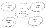
ノードには、メンバー、パーティ、端末、又は会議の参加者が含まれる。会議は、通常、少なくとも3つのノードを含んでおり、10や20、50、100、150、又はより多数のノードでさえあり得る。 Nodes include members, parties, terminals, or conference participants. A conference typically includes at least three nodes and may be 10, 20, 50, 100, 150, or even more nodes.
添付の図面を参照すると、幾つかの図面を通して、同じ参照符号が類似又は同様な部分を指している。特に図22を参照すると、電話会議システム(10)が示されている。システム(10)は、ネットワーク(40)を備えている。システム(10)は、ネットワーク(40)を介して互いに通信して、会議を構成する複数のノードを備えており、各ノードのライブシーンで会議が構成されるのが好ましい。各ノードは、変化が起こった場合に、その変化のみをその他のノードに送信する。
Referring to the accompanying drawings, like reference numerals designate similar or similar parts throughout the several views. With particular reference to FIG. 22, a
各ノードは、変化によって影響を受けるパーティのみに、その変化のみを伝える。 Each node only communicates the change to the party affected by the change.
本発明は、少なくとも3つのノード、例えばパーティ間で電気通信会議を開催する方法に関する。その方法は、ノード間のライブ会議を確立するステップを含んでおり、各ノードのライブシーンで会議が確立されるのが好ましい。会議に変化を起こすステップがある。その変化のみをノードに送信するステップがある。 The present invention relates to a method for holding a telecommunications conference between at least three nodes, for example parties. The method includes establishing a live conference between the nodes, preferably the conference is established in the live scene of each node. There are steps to change the meeting. There is a step of sending only the change to the node.
送信するステップは、変化によって影響を受けるノードのみに、その変化のみを伝えるステップを含むのが好ましい。変化を起こすステップは、ノードのステータスの1つに変化を起こすステップを含むのが好ましい。変化を起こすステップは、会議の状態の1つに変化を起こすステップを含むのが好ましい。ノードの1つから、全部ではない幾つかのノードのみに、指定のメッセージ(directed message)を送るステップがあるのが好ましい。確立するステップは、SIP NOTIFY/OK技術に基づいて会議を確立するステップを含むのが好ましい。 The transmitting step preferably includes only communicating the change to only the nodes affected by the change. The step of making a change preferably includes making a change to one of the node's statuses. Preferably, the step of making a change includes making a change to one of the conference states. Preferably, there is a step of sending a directed message from one of the nodes to only some but not all of the nodes. The establishing step preferably includes establishing a conference based on SIP NOTIFY / OK technology.
会議の変化は、ノードのステータスの1つの変化を含むのが好ましい。会議の変化は、会議の状態の変化を含むのが好ましい。複数のノードの1つは、全部ではない幾つかのノードのみに、指定のメッセージを送る。複数のノードは、SIP NOTIFY/OK技術に基づいて会議を確立するのが好ましい。各ノードは、コントローラ(19)と、コントローラ(19)及びネットワーク(40)と通信するネットワークインターフェイス(42)とを有するのが好ましい。コントローラ(19)は、そのノードに任意の変化をもたらし、その変化をネットワークインターフェイス(42)、さらにはネットワーク(40)を通じて、会議のその他のノードに送る。 The conference change preferably includes one change in the status of the node. The conference change preferably includes a conference state change. One of the nodes sends the specified message only to some but not all nodes. The nodes preferably establish a conference based on SIP NOTIFY / OK technology. Each node preferably has a controller (19) and a network interface (42) in communication with the controller (19) and the network (40). The controller (19) causes any changes to the node and sends the changes through the network interface (42) and even the network (40) to the other nodes in the conference.
本発明は、ネットワーク(40)用の電話会議用ノードに関しており、ネットワーク(40)は、その他のノードを伴っている。電話会議用ノードは、その他のノードと通信して、ライブ会議を構成するためのネットワークインターフェイス(42)を備えており、各ノードのライブシーンでライブ会議が構成されるのが好ましい。電話会議用ノードは、変化が起こった場合に、その変化のみをその他のノードに送信するコントローラ(19)を備えている。 The present invention relates to a conference call node for the network (40), and the network (40) is accompanied by other nodes. The telephone conference node preferably includes a network interface (42) for composing a live conference by communicating with other nodes, and the live conference is preferably configured in the live scene of each node. When a change occurs, the telephone conference node includes a controller (19) that transmits only the change to the other nodes.
好ましい実施例の動作では、大規模会議用の制御機構は、会議制御メッセージを用いて、コール上の全てのパーティを管理する。参加者は、会議制御メッセージを生成し、この会議制御メッセージは、送信されるストリームの特徴と、会議のその他の参加者から受信するストリームの所望のリストとを両方含む。この会議制御メッセージは、SIP NOTIFYイベントを介して、会議フォーカス又はホストに送られる。その後、会議フォーカスは、このメッセージを、このメッセージによって影響を受ける各パーティの出力キューに加える。会議フォーカスは、各パーティについてキューに入れられたイベントの全てを処理する際に、これらメッセージを送信する。メッセージが送られて、特定のパーティで受信されると、そのパーティは、出力するストリームのリストにリクエスト中のパーティを加える。また、会議制御メッセージは、ビデオストリームをオン若しくはオフにする、又は音声のみの制御のために「保留」にする要望を示すために送信され得る。 In the operation of the preferred embodiment, the control mechanism for large conferences uses conference control messages to manage all parties on the call. The participant generates a conference control message, which includes both the characteristics of the stream being transmitted and the desired list of streams received from other participants in the conference. This conference control message is sent to the conference focus or host via a SIP NOTIFY event. The conference focus then adds this message to the output queue of each party affected by this message. The conference focus sends these messages as it processes all of the queued events for each party. When a message is sent and received at a particular party, that party adds the requesting party to the list of streams to output. A conference control message may also be sent to indicate a desire to turn the video stream on or off, or “hold” for audio-only control.
大規模会議のシグナリングの発明
従来、ViPr会議は、オファー/アンサーモデルに基づいていた。このモデルでは、会議の全体的な状態が、会議参加者の間で交換される各メッセージで運ばれていた。例えば、P1乃至P5からなる5人の参加者間の会議を考える。この場合、これら5人のパーティは、ホストを呼ばれる中央ポイントを介して会議に接続されるだろう。ホストは、会議の全体的な状態を含むテーブルを作成するだろう。パーティP1乃至P3が、映像/音声を送信又は受信し、パーティP2及びP3が、音声のみを送信又は受信する場合、このテーブルのみが、全体的な状態を示すであろう。任意の変化が会議に起こる時はいつでも、ホストは、テーブルを再計算し、その情報を各人に送るだろう。例えば、P3がビデオの送信を停止する場合、以下のテーブル1がテーブル2に変更されて、その完全なテーブルが各人に送られる。
Large Conference Signaling Invention Traditionally, ViPr conferences were based on an offer / answer model. In this model, the overall state of the conference was carried in each message exchanged between conference participants. For example, consider a conference between five participants consisting of P1 to P5. In this case, these five parties will be connected to the conference via a central point called the host. The host will create a table that contains the overall state of the conference. If parties P1-P3 send or receive video / audio and parties P2 and P3 send or receive audio only, only this table will indicate the overall status. Whenever any change occurs in the meeting, the host will recalculate the table and send that information to each person. For example, if P3 stops transmitting video, the following table 1 is changed to table 2 and the complete table is sent to each person.

このスキームは、良く機能した。なぜならば、それは、現存するSIP基準に合致しており、基本的なSIPプロトコルの拡張を可能とし、ViPrスタイルの会議開催を可能にした。 This scheme worked well. Because it is in line with existing SIP standards, it allows the extension of the basic SIP protocol and allows ViPr style conferences to be held.
会議の参加者の数が、15人未満又はその程度の場合、このスキームは、良く機能した。それを超えると、全てのパーティを含むテーブルは、効率的に回されるには非常に大きくなる。さらに、会議の状態の如何なる変化についても、全てのパーティが影響を受ける訳ではない。処理する必要がないというメッセージで会議を溢れさせる必要はない。このモデルのもう1つの問題は、2つのSIPピア間で、アプリケーションレベルで、メディアに関係することなくメッセージを送る機能ができないことである。 This scheme worked well when the number of participants in the meeting was less than 15 or so. Beyond that, the table containing all parties becomes very large to be turned efficiently. Furthermore, not all parties are affected by any change in the state of the conference. There is no need to flood the meeting with messages that do not need to be processed. Another problem with this model is the inability to send messages between two SIP peers at the application level, regardless of media.
上述の問題を是正するために、我々は、この新しいスキームを発明した。この新しいスキームでは、以下に述べる重大な変化がなされている。 In order to correct the above problems, we have invented this new scheme. This new scheme has the following significant changes:
$ 会議の状態は、2つの点で変化し得る。参加者の何れか1人が、その状態の変化(パーティローカル)をリクエストしていたか、パーティの1人が、会議全体の変化(グローバルな変化)をリクエストしていた。このような如何なる変化がなされるといつでも、変化するパーティ又はグローバル会議状態を特定する情報のみが、会議の参加者の間でやり取りされる。テーブル2の例を使用すると、完全なテーブルではなく、P3に対応する情報のみが送出される。[つまり、P3に関する行のみが、その他の参加者に再送される。] Global Eventの例は、以下の通りである。
−−> Conference Name Change (会議の名前の変化)
−−> Conference Moderator Status Change (会議のモデレータの状態の変化)
−−> Floor Request Status Change (発言権リクエストの状態の変化)
−−> Conference Type Change (会議のタイプの変化)
−−> Conference Status Messages (パーティが会議の参加を拒絶されている等)
Party Eventの例は以下の通りである。
−−> Party Toggling camera (カメラを切り替えるパーティ)
−−> Party Toggling Hold status (ホールド状態を切り替えるパーティ)
−−> Party Delete (パーティの削除)
−−> Party Add (パーティの追加)
−−> Party Status Change (モデレータになる/モデレータの放棄)
−−> Party requesting a change in Receive Media Stream (受信メディアストリー ムの変化を要求するパーティ)
$ The state of the meeting can change in two ways. Either one of the participants was requesting a change in its state (party local), or one of the parties was requesting a change in the entire conference (global change). Whenever such changes are made, only information identifying the changing party or global conference state is exchanged between the conference participants. Using the example of table 2, only the information corresponding to P3 is sent, not the complete table. [In other words, only the row for P3 is retransmitted to the other participants. An example of Global Event is as follows.
−−> Conference Name Change
−−> Conference Moderator Status Change
---> Floor Request Status Change
−−> Conference Type Change
---> Conference Status Messages (for example, the party is refused to join the conference)
An example of Party Event is as follows.
---> Party Toggling camera
---> Party Toggling Hold status
−−> Party Delete
−−> Party Add
---> Party Status Change (become moderator / discard moderator)
−−> Party requesting a change in Receive Media Stream
$ 変化によって影響を受けるパーティのみが、変更された情報を受信する。 $ Only the party affected by the change will receive the changed information.
$ あるパーティP1から任意の数のパーティに、指定されたメッセージを送ることができる。例えば、P1は、メッセージをP2、P3及びP4に中継することを、ホストにリクエストできる。しかし、P5にはできない。これの最後の機能は重要であり、会議の開催において、グループベースでシグナリングを可能とする。 $ A specified message can be sent from any party P1 to any number of parties. For example, P1 can request the host to relay the message to P2, P3, and P4. However, P5 cannot. This last feature is important and allows for group-based signaling in conferencing.
この新しい設計は、SIP NOTIFY/OK手法に基づいており、新しいイベントパッケージを規定する。RFC3261及びRFC3264基準は、SIPの基本仕様を規定している。RFC3265は、イベントを使用するためのフレームワークを規定する。それらは、引用を以て本明細書の一部となる。 This new design is based on the SIP NOTIFY / OK approach and defines a new event package. The RFC 3261 and RFC 3264 standards define the basic specifications of SIP. RFC3265 defines a framework for using events. They are incorporated herein by reference.
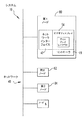
例えば、ホストは、常に、ViPr会議に必要とされる。実際に、会議のパーティは、お互いに直接シグナリングしているとは限らない。例えば、A、B、Cの間の会議コールがあるとする。3つのSIP Call Legがある。
−− Host to A
−− Host to B
−− Host to C
メディアは、A、B、Cの間で直接的に流れる。
For example, a host is always required for a ViPr conference. In fact, conference parties do not always signal each other directly. For example, suppose there is a conference call between A, B, and C. There are three SIP Call Legs.
--- Host to A
--- Host to B
-Host to C
Media flows directly between A, B, and C.
本発明において、Bは、現在、Aからビデオを受信しており、Cからもビデオを受信することを希望している。この変化は、以下の2つの方法の何れかで送信できるだろう。 In the present invention, B is currently receiving video from A and wishes to receive video from C as well. This change could be transmitted in one of two ways:
− Bは、NOTIFYをホストに送る。NOTIFYには、フィールド[called dest-party-list:C]があって、このメッセージがCのみに送られて良いことが示されている。
− 代わりに、Bは、このような如何なるフィールドにも明示的に置かれていないが、ホストは、このメッセージがCのみに影響することを検知でき、そのメッセージをCにのみに送信してもよい。
-B sends NOTIFY to the host. NOTIFY has a field [called dest-party-list: C], which indicates that this message may be sent only to C.
-Instead, B is not explicitly placed in any such field, but the host can detect that this message only affects C, and send it only to C. Good.
ビデオフォン
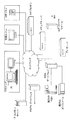
図8、図9、図10及び図11を参照すると、Sビデオを伴うソニー製の一般的なアナログビデオカメラ(32)のような撮像装置(30)が、該撮像装置(30)で得られるシーンの画像を電気信号に変換する。その電気信号は、配線を通って、フィリップス製SAA7144 NTSC/PAL/デコーダのようなビデオデコーダ(34)に送られる。ビデオデコーダ(34)は、電気信号をデジタル信号に変換して、BT656フォーマットのようなシーンの画素のストリームとしてそれらを送る。画素のストリームは、ビデオデコーダ(34)から送り出されて、第1ストリームと、第1ストリームと同じである第2ストリームとに分けられる。エンコーダ(36)は、IBM eNV 420エンコーダであるのが好ましく、画素の第1ストリームを受信し、それを処理してMPEG-2フォーマットのデータストリームを生成する。ビデオエンコーダ(36)で生成されたデータストリームは、カメラで生成された際と比較して約50分の1のサイズに圧縮される。MPEG-2ストリームは、エンコードされたデジタルストリームであって、引き続いてパケット化される前にフレームバッファリングされないので、遅延が最小化されている。エンコードされたMPEG-2デジタルストリームは、フィールドプログラマブルゲートアレイ(FPGA)(38)と、MPEG-2ストリームが与えられるソフトウエアとを用いて、RTPによってパケット化される。そして、PLX 9054 PCIインターフェイス(44)を通じて、ネットワークインターフェイス(42)を用いて、イーサネット(登録商標)802.P、又は毎秒155メガビットのATMのようなネットワーク(40)に送信される。必要ならば、CNNや映画のようなVCRやテレビジョンショーに関するビデオストリームがデコーダ(34)で受信され、ディスプレイコントローラ(52)に直接供給されて表示される。デコーダコントローラ(46)は、FPGA(38)に配置されてデコーダ(34)に接続されており、デコーダ(34)の動作を制御する。
Videophone Figure 8, Figure 9, with reference to FIGS. 10 and 11, an imaging device such as a Sony conventional analog video camera (32) with S-video (30), in the imaging device (30) The obtained scene image is converted into an electrical signal. The electrical signal is sent through a wire to a video decoder (34) such as a Philips SAA7144 NTSC / PAL / decoder. The
また、デジタルカメラ(47)を用いる場合、カメラで生成された結果のストリームは、既にデジタルフォーマットであって、デコーダ(34)に供給される必要はない。デジタルカメラ(47)から送られるデジタルストリームは、BT 656フォーマットであって、カメラから直接に第1及び第2ストリームに分けて送り出されて、ビデオデコーダ(34)を通ることはない。 When the digital camera (47) is used, the resulting stream generated by the camera is already in a digital format and need not be supplied to the decoder (34). The digital stream sent from the digital camera (47) is in the BT 656 format and is sent directly from the camera into the first and second streams and does not pass through the video decoder (34).
さらに、1394 インターフェイスファイヤラインカメラ(48)のようなファイヤラインカメラ(48)を用いると、デジタル信号を直接FPGA(38)に供給できる。ファイヤラインカメラ(48)を用いると、FPGA(38)から非常に短い距離を超えてデータストリームの生成が行われる場合に、デジタル信号が、例えばケーブルによって、ファイヤラインカメラ(48)から長い距離でサポートされる利点がある。FPGA(38)は、ファイヤラインカメラ(48)から送られるデジタル信号をエンコーダ(36)に供給して、上述の処理が行われる。そして、FPGA(38)は、以下に説明するように、低フレームレートのストリームを生成する。 Further, when a fire line camera (48) such as a 1394 interface fire line camera (48) is used, a digital signal can be directly supplied to the FPGA (38). With the fireline camera (48), when the data stream is generated over a very short distance from the FPGA (38), the digital signal is transmitted from the fireline camera (48) at a long distance, for example by cable. There are benefits to be supported. The FPGA (38) supplies the digital signal sent from the fire line camera (48) to the encoder (36), and the above processing is performed. Then, the FPGA (38) generates a low frame rate stream as described below.
第2ストリームはFPGA(38)に供給されて、FPGA(38)及びソフトウエアは、モーションJPEGストリームのような低フレームレートのストリームを生成する。第2ストリームは、第1ストリームよりも低い帯域幅を必要とする。FPGA(38)及びメインコントローラ(50)は、ソフトウェアによるエンコードを用いて、この低フレームレートのストリームを圧縮及びパケット化し、それをPCIインターフェイス(44)に供給する。続いて、PCIインターフェイス(44)は、ネットワークインターフェイスカード(56)を通じてネットワークインターフェイス(42)にそれを転送する。ネットワークインターフェイス(42)は、それをネットワーク(40)に送信する。エンコードされたMPEG-2デジタルストリーム及び低フレームレートストリームは、基本的に同じであるが独立した2つのデータストリームである。しかしながら、低フレームレートストリームは、MPEG-2データストリームと比較して縮小されており、MPEG-2ストリームと比較して、同一シーンの表示が小さく、ネットワーク(40)のリソースが少なくてすむ。 The second stream is supplied to the FPGA (38), and the FPGA (38) and software generate a low frame rate stream such as a motion JPEG stream. The second stream requires a lower bandwidth than the first stream. The FPGA (38) and main controller (50) use software encoding to compress and packetize this low frame rate stream and provide it to the PCI interface (44). Subsequently, the PCI interface (44) transfers it to the network interface (42) through the network interface card (56). The network interface (42) transmits it to the network (40). The encoded MPEG-2 digital stream and the low frame rate stream are basically the same but two independent data streams. However, the low frame rate stream is reduced as compared with the MPEG-2 data stream, and the display of the same scene is small and the resources of the network (40) are small as compared with the MPEG-2 stream.
ネットワーク(40)上では、各デジタルストリームは、所望の受信ビデオフォン(15)に運ばれる。会議のパーティの数が2を超える場合には、各デジタルストリームは、複数の受信ビデオフォン(15)に運ばれる。データは、SIPを用いてルーティングされる。受信ビデオフォン(15)のネットワークインターフェイスカード(56)は、第1及び第2データストリームのパケットを受信し、パケットのデータと、メインコントローラで選択されたビデオストリーム(第1又は第2)とを受信メモリに送る。受信ビデオフォン(15)のメインコントローラ(50)は、ソフトウエアを用いて、選択された受信データストリームをデコード及び伸張し、それをディスプレイコントローラ(52)に転送する。ディスプレイコントローラ(52)は、一般的なスケーリングハードウエアを用いて、VGAデジタルフラットパネルディスプレイに再生画像を表示する。受信ビデオフォン(15)のユーザは、タッチスクリーン(74)を用いて、2つのデータストリームのうちどちらが表示されるかを選択する。必要に応じて、ユーザは両方を選択し、シーンの大きい画像と小さい画像とが表示される。しかしながら、送信ビデオフォン(15)から送られる両方のストリームが表示されることは、通常起こらないだろう。表示用のプロトコルの説明は、以下で行われる。シーンの大きい画像又はシーンの小さい画像の何れかを選択するオプションを有することで、ユーザは、システム(10)のリソースを割り当てて、見る者にとってその時により重要である者が、大きく鮮明な画像で見られるように選択できる。一方で、ユーザがまだ見たいと思うがその時に重要ではない者も、引き続き見られ得る。
On the network (40), each digital stream is carried to the desired receiving videophone (15). If the number of parties in the conference exceeds 2, each digital stream is carried to a plurality of receiving videophones (15). Data is routed using SIP. The network interface card (56) of the receiving videophone (15) receives the packets of the first and second data streams, and transmits the packet data and the video stream (first or second) selected by the main controller. Send to receive memory. The main controller (50) of the receiving videophone (15) uses software to decode and decompress the selected received data stream and forward it to the display controller (52). The
2以上のビデオストリームがある場合(会議コールが起こっている場合)、ディスプレイコントローラ(52)は、個々のビデオストリームをディスプレイ(54)に並べて表示する。ディスプレイ(54)に並べて形成された画像はクリップされており(clipped)、縮小されていない。シーンにおける物の大きさは変化しておらず、単に、各データストリームのシーンにおける夫々の側の外領域が削除される。必要ならば、シーンの小さい画像に関するストリームの画像は、ディスプレイ(54)のスクリーンにて、右下隅に並べて表示される。図9に示すように、ディスプレイコントローラ(52)は、一般的なデジタルビデオをLCDコントローラ(72)に供給する。ディスプレイコントローラ(52)は、ATI又はNvidia製であり、一般的なVGAコントローラである。LCDコントローラ(72)は、ディスプレイコントローラ(52)から送られる一般的なデジタルビデオを得て、フィリップスや富士通のパネルのような、使用する特定のパネルに適した画像を作成する。
When there are two or more video streams (when a conference call is occurring), the display controller (52) displays the individual video streams side by side on the display (54). The images formed side by side on the display (54) are clipped and not reduced. The size of the object in the scene has not changed, and the outer area on each side of the scene for each data stream is simply deleted. If necessary, the stream image relating to the small image of the scene is displayed side by side in the lower right corner on the screen of the display (54). As shown in FIG. 9, the display controller (52) supplies general digital video to the LCD controller (72). The
画像のクリップをさらに向上させるため、単に、画像の部分的削除を外側端部から中央に向けて行う代わりに、関係ある情報を示さない部分を画像からクリップする。画像の左側又右側にて人物が話している場合、外端部の各々からクリップする代わりに、人物が画像の右側にいる場合、画像の左側からクリップするのが望ましく、人物が画像の左側にいる場合、画像の右側からクリップするのが望ましい。外端部の各々からクリップすると、人物の部分が失われることが起こり得る。ビデオトラッキングを用いることで、形成される画像を見て、画像内で変化が起こっている場所を解析して、画像内で人物がいる場所を特定する。人物は、画像のその他の領域に対して相対的に動いており、この相対移動を特定することで、画像における人物の位置が決定され得る。このビデオトラッキングによって、クリップを、変化が最も少なくなる端部又は複数の端部にて起こすことが可能となる。代わりに、又はビデオトラッキングと併せて、オーディオトラッキングを用いて、画像のクリップを行うことを補助できる。ビデオフォン(15)はマイクロホンアレイを有しており、マイクロホンアレイの数々の要素に音が達する異なる瞬間にて、一般的な三角測量(triangulation)を行うことで、マイクロホンアレイに対して人物が何処に配置されているかを決定できる。画像になっているシーンに対するマイクロホンの位置は知られているので、画像における人物の位置も分かる。 To further improve the clipping of the image, instead of simply performing partial deletion of the image from the outer edge toward the center, the portion that does not show relevant information is clipped from the image. If a person is speaking on the left or right side of the image, instead of clipping from each of the outer edges, it is desirable to clip from the left side of the image when the person is on the right side of the image. If so, it is desirable to clip from the right side of the image. Clipping from each of the outer ends can cause loss of a person's part. By using video tracking, a place where a person is present in the image is specified by looking at the formed image and analyzing the place where the change occurs in the image. The person is moving relative to other areas of the image, and by specifying this relative movement, the position of the person in the image can be determined. This video tracking allows the clip to occur at the edge or edges where the change is minimal. Alternatively, or in conjunction with video tracking, audio tracking can be used to help clip images. The videophone (15) has a microphone array, and by performing general triangulation at different moments when the sound reaches the various elements of the microphone array, where the person is with respect to the microphone array. Can be determined. Since the position of the microphone with respect to the scene in the image is known, the position of the person in the image is also known.
ビデオフォン(15)の機能は、モニタ上のタッチスクリーン(74)で制御される。タッチスクリーン(74)は、一般的なガラスのタッチスクリーンであって、タッチスクリーンコントローラ(76)に生信号を供給する。公知のように、生信号は、ユーザが所定の場所でガラスに触ると生じる超音波で感知される。そして、タッチスクリーンコントローラ(76)は生信号を得ると、それらをスクリーン上のX及びY位置に関する有意義な情報に変換して、この情報をメインコントローラ(50)に送る。
The function of the
テレビジョン又はVCR接続が利用される場合、テレビジョン又は映画はデコーダ(34)に供給されて、その供給は、ビデオフォン(15)で受信されるその他のビデオ信号と同様に制御される。テレビジョン又は映画は、ディスプレイ(54)上にて、別のビデオフォン(15)に関係したビデオのシーンの横に表示される。 If a television or VCR connection is used, the television or movie is fed to the decoder (34), which is controlled in the same way as other video signals received at the videophone (15). The television or movie is displayed on the display (54) next to the video scene associated with another videophone (15).
シーンのオーディオストリームは、基本的に、オーディオビデオストリームと並行な同様の経路を通るが、オーディオストリームは、マイクロホン、サウンドカード、ヘッドセット又はハンドセットのようなオーディオレシーバ(58)から、CSクリスタル4201オーディオインターフェイス(60)又はコーデック製の同様なインターフェイスに供給される。オーディオインターフェイス(60)は、ボリューム及びミキシングの制御に加えて、信号のアナログデジタル変換及びデジタルアナログ変換を行う。オーディオインターフェイス(60)は、オーディオ信号をデジタル化して、TCI 320C6711 又は 6205 DSP(62)に送る。その後、DSP(62)は、デジタル化されたオーディオストリームをパケット化し、そのデジタル化されたオーディオストリームをFPGA(38)に転送する。続いて、FPGA(38)は、それをPCIインターフェイス(44)に与える。オーディオストリームは、その後、ネットワークインターフェイスカード(56)を通ってネットワーク(40)に送信される。オーディオストリームは受信ビデオフォン(15)で受信されて、FPGA(38)を通ってDSP(62)に、さらにはオーディオインターフェイス(60)に送られる。デジタル信号は、オーディオインターフェイス(60)にてアナログ信号に変換されて、スピーカ(64)で再生される。
The audio stream of the scene basically follows a similar path in parallel with the audio video stream, but the audio stream is sent from an audio receiver (58) such as a microphone, sound card, headset or handset to the CS crystal 4201 audio. Supplied to interface (60) or similar interface made by codec. The audio interface (60) performs analog-to-digital conversion and digital-to-analog conversion of signals in addition to volume and mixing control. The audio interface (60) digitizes the audio signal and sends it to the TCI 320C6711 or 6205 DSP (62). Thereafter, the DSP (62) packetizes the digitized audio stream, and transfers the digitized audio stream to the FPGA (38). Subsequently, the FPGA (38) provides it to the PCI interface (44). The audio stream is then transmitted to the network (40) through the network interface card (56). The audio stream is received by the receiving
ネットワークインターフェイスカード(56)は、ネットワーク(40)に送信されるオーディオパケット及びビデオパケットの各々にタイムスタンプを付す。ビデオフォン(15)が受信したオーディオ及びビデオパケットが処理される速度は、充分に速いので、人間の目及び耳は、シーンのビデオに合わせられるオーディオのずれを、視聴の際に識別できない。20〜30ミリ秒未満という制限が、シーンのオーディオ及びビデオ情報の処理でなされて、シーンのビデオ及びオーディオの関係が維持される。シーンのオーディオ及びビデオの同期を受信ビデオフォン(15)にて受信される際に保証するために、各パケットのタイムスタンプが参照されて、対応するオーディオベースのパケットとビデオベースのパケットが受信ビデオフォン(15)にて並べられて、対応するように基本的に同時に再生される。これによって、受信ビデオフォン(15)のユーザに識別されるようなシーンのビデオ及びオーディオのずれは存在しなくなる。
The network interface card (56) attaches a time stamp to each of the audio packet and video packet transmitted to the network (40). The rate at which the audio and video packets received by the
ENC−DSPボードは、IBM eNV 420 MPEG−2エンコーダ及びサポート回路と、オーディオエンコード及びデコードをするDSP(62)と、PCIインターフェイス(44)とを含んでいる。それは、高性能PC(68)プラットホーム及びディスプレイ(54)システム(10)に与えられる完全なビデオフォン(15)端末機能に必要なハードウエアを含んでいる。それは、フルサイズのPCI2.2に準拠したデザインである。カメラ、1又は複数のマイクロホン、及びスピーカ(64)は、このボードにインターフェイスする。DSP(62)は、オーディオエンコード、デコード、ミキシング、ステレオ配置(stereo placement)、レベルコントロール、ギャップフィリング(gap filling)、パケット化、及びその他のオーディオ機能、例えば、ステレオAEC、ビームステアリング、ノイズキャンセル、キーボードクリックキャンセルやデリバーバレイション(de-reverberation)を行う。FPGA(38)は、セロクシア(Celoxia)(ヘンデル−C(Handel-C))ツールを用いて開発され、再構成可能である。レイアウトは、1〜3百万ゲートレンジで部品をサポートする。 The ENC-DSP board includes an IBM eNV 420 MPEG-2 encoder and support circuit, a DSP (62) for audio encoding and decoding, and a PCI interface (44). It includes the hardware necessary for full videophone (15) terminal functionality provided to a high performance PC (68) platform and display (54) system (10). It is designed to comply with full size PCI 2.2. A camera, one or more microphones, and a speaker (64) interface to this board. The DSP (62) is capable of audio encoding, decoding, mixing, stereo placement, level control, gap filling, packetization, and other audio functions such as stereo AEC, beam steering, noise cancellation, Perform keyboard click cancellation and de-reverberation. FPGA (38) was developed using the Celoxia (Handel-C) tool and is reconfigurable. The layout supports parts in the 1-3 million gate range.
このボードは、デジタルカメラ(47)チップインターフェイス、ハードウエア又は「ビデオDSP」ベースのマルチチャンネルビデオデコーダ(34)インターフェイス、DVI入出力コネクタを用いたビデオオーバーレイを含んでおり、ビデオオーバーレイと共に、フルダンプなフレームバッファを可能としている。 The board includes a digital camera (47) chip interface, hardware or “video DSP” based multi-channel video decoder (34) interface, and a video overlay using a DVI input / output connector. A frame buffer is possible.
NTSC又はPALビデオ信号を用いて、エンコーダ(36)は、640×480である、好ましくは720×480又はより高解像度である高品質なビデオストリームを生成する。ビットレートは、フレーム当たりの最大ビットが制限されるように制御されて、ネットワーク(40)に渡って伝送遅延が抑制される。デコーダ(34)は、第1マクロブロックのデータを受信すると、一枚のデコードを開始する。ある種のバッファリングが行われてもよく、軽微なジッタが調整されて、画像が向上する。
Using the NTSC or PAL video signal, the
MPEG-2は、広く使用及び実施されており、DVD及びVCDのエンコード、デジタルVCR、及びTiVoのようなビデオ録画装置に加えて、DSSやその他のデジタルTV放送の基礎となっている。通常、4から50Mbit/secのビデオ伝送が選択されると考えられる。MPEG-2は、広く使用されているので、比較的低コストであり、デコードについての、つい最近ではさらにエンコードについての高集積化されたソリューションが、現在商業的に入手可能である。 MPEG-2 is widely used and implemented, and is the basis for DSS and other digital TV broadcasts in addition to video recording devices such as DVD and VCD encoding, digital VCR, and TiVo. Usually, it is considered that video transmission of 4 to 50 Mbit / sec is selected. Since MPEG-2 is widely used, it is relatively low cost and a highly integrated solution for decoding, and more recently for encoding, is now commercially available.
MPEG-2は、一般的な圧縮方法と考えられるよりは、むしろエンコードされたビデオのシンタックス(syntax)であると考えられる。仕様がシンタックス及びエンコード方法を定める一方で、定められたシンタックスに従う限り、その方法の使用について非常に広い自由度がある。この理由から、MPEG-2に関する一般化は、しばしば誤り又は不正確である。特定の用途へのMPEG-2のパフォーマンスを評価するためには、特定のエンコード方法と意図した応用について、より低いレベルの詳細まで達する必要がある。 MPEG-2 is considered the syntax of the encoded video rather than being considered a general compression method. While the specification defines the syntax and encoding method, as long as it follows the defined syntax, there is a great deal of freedom in using that method. For this reason, generalizations relating to MPEG-2 are often erroneous or inaccurate. In order to evaluate the performance of MPEG-2 for a particular application, it is necessary to reach a lower level of detail for the particular encoding method and intended application.
ネットワーク(40)に関連した問題と共に、低遅延のエンコード及びデコードの問題は、ビデオフォン(15)プロジェクトにとって興味深い。MPEG-2のアルゴリズムにおける3つの主要な問題があり、これらはネットワーク(40)に渡って低遅延で高い品質のビデオを得るために理解される必要がある。 Along with the problems associated with the network (40), the low latency encoding and decoding problems are of interest to the videophone (15) project. There are three major problems in the MPEG-2 algorithm that need to be understood to obtain high quality video with low latency across the network (40).
≡ GOP(Group Of Pictures)構造及びその遅延に与える効果。
≡ 遅延及びネットワーク(40)の要求に与えるビットレート、エンコードされたフレームサイズ変化、VBVバッファの効果。
≡ パケット損失による、質に与えるGOP構造の効果。
≡ Effect on GOP (Group Of Pictures) structure and its delay.
≡ Bit rate, encoded frame size change, VBV buffer effect on delay and network (40) requirements.
≡ GOP structure effect on quality due to packet loss.
GOP構造及び遅延:
MPEG-2は、3種類のエンコードフレーム:I,P及びBを定義している。最も普通に使用されるGOP構造は、16フレーム長のIPBBPBBPBBPBBPBBである。この構造の問題は、Bフレームは前後のフレームから推測される動きであるので、連続するBフレームの各々について、Bフレームのエンコードが開始できる前に、次のフレームがキャプチャされる必要があることである。各フレームは33msecであるので、これは、Bフレームがない構造を超えて、このGOP構造に最小で66msecの遅延を加える。このことによって、I及び/又はPフレームのみを含んでおり、MPEG-2の仕様で、SP@ML(シンプルプロファイル)エンコードとして定められた、低遅延のGOP構造が導かれる。
GOP structure and delay:
MPEG-2 defines three types of encoding frames: I, P, and B. The most commonly used GOP structure is 16 frames long IPBBPBBPBBPBBPBB. The problem with this structure is that the B frame is a motion that is inferred from the previous and subsequent frames, so for each successive B frame, the next frame must be captured before the B frame can be encoded. It is. Since each frame is 33 msec, this adds a minimum of 66 msec delay to this GOP structure beyond the structure without B frames. This leads to a low-delay GOP structure that includes only I and / or P frames and is defined as SP @ ML (simple profile) encoding in the MPEG-2 specification.
ビットレート、エンコードフレームサイズ、及びVBV:
Bフレームが除かれてエンコード遅延が最小化されると、GOP構造は、Iフレームと、Iフレームに対するPフレームとで構成される。Iフレームは、完全にフレーム内符号化されているので、これを行うために多くのビットが必要とされて、次のPフレームのビットは少なくなる。
Bit rate, encoding frame size, and VBV:
When the B frame is removed and the encoding delay is minimized, the GOP structure is composed of an I frame and a P frame for the I frame. Since the I frame is fully intra-coded, more bits are needed to do this and fewer bits in the next P frame.
IフレームはPフレームの8倍大きく、そのビットレートは公称(nominal)の5倍である可能性があることに留意すべきである。このことは、ネットワーク(40)の要求と遅延とに直接的な影響を与える。帯域幅に制限がある場合、Iフレームはネットワーク(40)のリストリクションにてバッファリングされて、結果として限定されたセグメントに渡って、複数のフレームの時間の遅延が加わるであろう。再生レートがネットワーク(40)の帯域幅ではなく、ビデオに合わせられるので、このバッファはレシーバに適合する必要がある。上記データで用いられるサンプルは、低動作オフィスシーンであった。シーンが変化する高動作のコンテントでは、フレームには、コンテントに応じたビットが割り当てられて、シーンが変化する際には幾つかの大きなPフレームが生じるであろう。
It should be noted that an I frame is 8 times larger than a P frame, and its bit rate may be 5 times the nominal. This has a direct impact on network (40) requirements and delays. If bandwidth is limited, I-frames will be buffered in the
この振る舞いを制御するために、MPEG-2は、VBVバッファ(ビデオバッファリングベリファ)を使用する。VBVバッファは、最大エンコードフレームサイズと公称のビットレートとの間の比率をある程度制御する。公称ビットレートで示されたサイズの2倍より小さくIフレームが制限されるように、VBVを確実に制限することで、加えられるバッファリング遅延を1フレーム時間に制限できる。VBVのサイズを制限することによって、画質が犠牲となる。Iフレームが大きい理由は、次のPフレームの良いベースを与えるためであり、Iフレームのサイズが制限される場合、質は、より低いビットレート(<4Mビット)へと顕著に低下する。2Mビットでは、平均フレームサイズは8Kバイトであり、このサイズの2倍でさえも、Iフレームと同様にDCT圧縮される320×240のJPEG画像を、良質でエンコードするのには不十分である。 In order to control this behavior, MPEG-2 uses a VBV buffer (video buffering verifier). The VBV buffer controls to some extent the ratio between the maximum encoded frame size and the nominal bit rate. By reliably limiting VBV so that I frames are limited to less than twice the size indicated by the nominal bit rate, the added buffering delay can be limited to one frame time. By limiting the size of the VBV, image quality is sacrificed. The reason for the large I frame is to give a good base for the next P frame, and when the size of the I frame is limited, the quality is significantly reduced to lower bit rates (<4 Mbits). At 2Mbit, the average frame size is 8K bytes, and even twice this size is not enough to encode good quality 320x240 JPEG images that are DCT compressed as well as I frames. .
Iフレームのみのエンコードによって、エンコードフレームサイズは、より一致するが、質がより低下する。低ビットレートのIフレームのみをエンコードすることは、MPEG-2のアルゴリズムの圧縮能力の大部分を活用していない。 Encoding only I frames results in a more consistent encoding frame size but lower quality. Encoding only low bit rate I frames does not take advantage of most of the compression capability of the MPEG-2 algorithm.
MPEG-2の仕様は、CBR(Constant Bit Rate)及びVBR(Variable Bit Rate)モードを定めており、ストリーム内にて可変なGOP構造を可能とする。CBRモードは、必要に応じてパッディング(padding)を行って、各GOPについて一定数のビットを生成するように定められている。VBRは、エンコード帯域幅を可変にすることで、一定の質を得ることを意図としており、より簡単なセクションにおけるより低いビットレートでこのことが補償されている限り、ストリームにて、困難なエンコード領域により多くのビットを割り当てることが可能となる。VBRは、2(two)パス又はシングルパステクニックを用いて実現できる。可変GOP構造によって、例えば、シーンが遷移する境界におけるIフレームの配置にて、目で見える圧縮アーチファクトが除去される。低遅延が求められており、VBR又は可変GOPを実施するためにビットを小さくする必要があるので、これらのモードは、ビデオフォン(15)の用途には、ほとんど関連がない。
The MPEG-2 specification defines CBR (Constant Bit Rate) and VBR (Variable Bit Rate) modes, and enables a variable GOP structure within a stream. The CBR mode is defined to generate a certain number of bits for each GOP by performing padding as necessary. VBR is intended to achieve a constant quality by making the encoding bandwidth variable, and as long as this is compensated for at a lower bit rate in a simpler section, difficult encoding in the stream More bits can be allocated to the area. VBR can be implemented using a two-pass or single-pass technique. The variable GOP structure eliminates visible compression artifacts at, for example, the placement of I frames at the scene transition boundaries. These modes are of little relevance for
典型的なGOP構造におけるP及びBフレームは、Iフレームと、以前のP及びBフレームとに依存しているので、データの損失は、次のIフレームまでの全てのフレームに影響を与えて、エラーが生じる。このことは、また、スタートアップの待ち時間に影響を与えて、例えば、DSSシステム(10)でチャンネルをオンにする場合、デコーダ(34)は、画像の表示を開始する前にIフレームを待つ。このために、GOP長、構造及びビットレートは、用途及び配信システム(10)に対して調整される必要がある。IPを用いたリアルタイムコラボレーションの場合、信頼性のあるプロトコルを用いてハンドシェイク及び再送するのに要する遅延を受け入れる余裕はないので、遅れたパケットは失われたとして取り扱う必要があり、RTPやUDPのような信頼性がない転送プロトコルが用いられる。パケット損失がビデオの質に与える効果について、様々な解析がなされており、典型的なIPB GOP構造では、1%のパケット損失が30%のフレーム損失を生じる事が示されている。より短いGOP構造、究極的にはIフレームのみのストリーム(質の損失がある)は、これを幾分抑える。また、FEC(Forward Error Correction)テクニックは、損失が生じると、これを幾分抑えることができる。しかし、MPEG-2の問題の一つは、明らかに、データ損失をあまり許容できないことである。 Since P and B frames in a typical GOP structure depend on I frames and previous P and B frames, data loss affects all frames up to the next I frame, An error occurs. This also affects the start-up latency, for example if the channel is turned on in the DSS system (10), the decoder (34) waits for an I frame before starting to display an image. For this, the GOP length, structure and bit rate need to be adjusted for the application and distribution system (10). In the case of real-time collaboration using IP, there is no room to accept the delay required to handshake and retransmit using a reliable protocol, so it is necessary to handle delayed packets as lost, and RTP and UDP A non-reliable transfer protocol is used. Various analyzes have been made on the effect of packet loss on video quality, and in a typical IPB GOP structure it has been shown that 1% packet loss results in 30% frame loss. A shorter GOP structure, ultimately an I-frame only stream (with loss of quality) suppresses this somewhat. Also, the FEC (Forward Error Correction) technique can suppress this somewhat if a loss occurs. However, one of the problems with MPEG-2 is clearly that the data loss is not very tolerable.
連続的Pフレームエンコードと呼ばれるGOP構造は、上記の問題の全てに対処して、比較的低ビットレートで、優れたビデオの質をビデオフォン(15)に与える。連続的Pエンコードは、Pフレーム内にて、フレームのマクロブロックをフレーム内エンコードする機能を用いる。各フレームにて、16×16ピクセルのマクロブロックの擬似乱数セットをエンコードし、その他をモーションコーディング(motion-coding)して、Iフレームのビットの同等物を各フレームに分布させる。擬似乱数を用いてマクロブロックの選択をすると、頻出する時間スケールで全てのブロックが更新されるので、スタートアップとシーンの変化は、妥当な方法で処理される。
The GOP structure, called continuous P-frame encoding, addresses all of the above problems and gives the
IBMは、このアルゴリズムをS420エンコーダで実施しており、フルフレームDCTアップデートレートを8フレーム(3.75回/秒)に設定している。典型的なオフィス及び会議のコンテントでは、その結果は、非常に優れたものとなる。エンコードによる遅延、エンコードされたフレームのサイズの変化、パケット損失は、ビデオフォン(15)にとって非常に理想的な振る舞いとなっている。エンコードされたサンプルを見ると、シーン変化と非常に動的なコンテントについてはエンコーダ(36)アーチファクトが現れるが、コラボレーションで典型的である話し手の顔のコンテントについては、質は非常に良い。 IBM implements this algorithm with the S420 encoder and sets the full frame DCT update rate to 8 frames (3.75 times / second). With typical office and conference content, the results are very good. Encoding delays, encoded frame size changes, and packet loss are very ideal behaviors for videophones (15). Looking at the encoded sample, the encoder (36) artifacts appear for scene changes and very dynamic content, but the quality of the speaker's face content typical of collaboration is very good.
高質のオーディオは、効果的なコミュニケーションにおいて欠かすことができない。高質とは、全二重であり、帯域幅が7kHzであり(電話は3.2kHz)、信号対雑音比が30dBより大きく、知覚できるエコー、クリッピング又はゆがみがないことである。設定は非常に容易で、可能な限りケーブルは少ない。オンボードの診断は、問題及びその解決方法とを示す。スピーカ(64)からの音には、音のレベルの高低に関係なく、大きなはじけ音やうなり音が無い。 High quality audio is essential for effective communication. High quality is full-duplex, has a bandwidth of 7 kHz (telephone 3.2 kHz), a signal-to-noise ratio greater than 30 dB, and no perceptible echo, clipping or distortion. Setup is very easy and has as few cables as possible. On-board diagnostics indicate the problem and how to solve it. The sound from the loudspeaker (64) does not have a loud rushing sound or a roaring sound regardless of the level of the sound.
失われた又は遅れたパケットのオーディオ信号は、先のオーディオ信号に基づいて「満たす」ことができる。オーディオバッファは、ネットワーク(40)のジッタとオーディオに加わる遅延との間のバランスとして約50msとすべきである。320サンプル又は20msの現在のパケットサイズを減らすならば、エンコード及びデコード遅延が減るであろう。しかしながら、20msは、RTPパケットの一般的なデータ長である。
The audio signal of the lost or delayed packet can be “filled” based on the previous audio signal. The audio buffer should be approximately 50 ms as a balance between the jitter of the
以下に説明するプロセスの幾つかは、市販の製品で利用されている。しかしながら、コスト低減と集積化を図るために、それらはDSP(62)として実施されるであろう。別の実施例では、1つのDSP(62)が上記のプロセスに加えて音響エコーキャンセルをも行うのではなく、第2DSP(62)が、音響エコーキャンセルを行い得る。 Some of the processes described below are used in commercial products. However, they will be implemented as DSPs (62) for cost reduction and integration. In another embodiment, instead of one DSP (62) performing acoustic echo cancellation in addition to the above process, a second DSP (62) may perform acoustic echo cancellation.
オーディオシステム(10)は、送信及び受信セクションを有している。送信セクションは、以下の要素で構成される。 The audio system (10) has transmission and reception sections. The transmission section is composed of the following elements.
マイクロフォン:
スピーカフォンに対する主要な不満の一つに、離れた所で聞く音がこもってしまうことがある。このこもった音は、部屋の反響によって生じるものであり、直接音のパワーに対する反射(反響)音のパワーの比、として考えるのが良い。現在、ピックアップを改善する最も良い方法は、マイクロフォンを話し手に近づけて配置して、直接音のパワーを増加させることである。オフィス環境では、マイクロフォンは、PC(68)のモニタに、ビデオフォン(15)端末に、ホワイトボードに配置できる。
microphone:
One of the main complaints about speakerphones is that the sounds you hear at a distance can be muffled. This muffled sound is generated by room reverberation and should be considered as the ratio of the power of the reflected (echo) sound to the power of the direct sound. Currently, the best way to improve pickup is to place the microphone closer to the speaker to increase the power of the direct sound. In an office environment, the microphone can be placed on the whiteboard, on the monitor of the PC (68), on the videophone (15) terminal.
自動ゲイン制御:
各マイクロフォンのプリアンプのゲインは自動的に調節されて、ADCレンジが十分に使用される。プリアンプゲインは、AEC及びノイズリダクションのようなその他のオーディオプロセスに送られる。
Automatic gain control:
The gain of each microphone preamplifier is automatically adjusted to fully use the ADC range. The preamplifier gain is sent to other audio processes such as AEC and noise reduction.
CODEC:
簡単な形式では、これはADCデバイスとなる。しかしながら、テキサスインスツルメント及びアナログデバイスインコーポレイテッドのような幾つかの企業は、アナログアンプとアナログマルチプレクサを具えるCODECを有している。また、同様に制御されるDACがチップ上にある。先に説明した自動ゲイン制御は、CODECで実施されて、DSP(62)で制御される。
CODEC:
In a simple form, this becomes an ADC device. However, some companies, such as Texas Instruments and Analog Devices, Inc. have CODECs that include analog amplifiers and analog multiplexers. There is also a similarly controlled DAC on the chip. The automatic gain control described above is performed by CODEC and controlled by DSP (62).
ノイズリダクション:
2つの方法のノイズリダクションを用いることで、SNRを改善できる。第1の方法は、一般にノイズゲーティング(noise gating)と呼ばれており、現在の信号レベルに応じてチャンネルをオン・オフする。第2の方法は、適応ノイズキャンセル(ANC)であり、マイクロフォンの信号から不要なノイズを取り去る。オフィス環境では、ANCを用いて、PAアナウンス、ファンノイズ、ある場合にはキーボードのクリック音でさえ除去できるであろう。
noise reduction:
The SNR can be improved by using two methods of noise reduction. The first method is generally called noise gating, and the channel is turned on / off according to the current signal level. The second method is adaptive noise cancellation (ANC), which removes unwanted noise from the microphone signal. In an office environment, ANC could be used to remove PA announcements, fan noise, and in some cases even keyboard clicks.
ノイズリダクション又はゲーティングのアルゴリズムは、クールエディトやゴールドウェーブのような市販のオーディオ編集パッケージで利用できる。このようパッケージは、特別な効果を加えて、記録からスクラッチ及びポップノイズを除去し、テープ記録からヒスノイズも除去できる。 Noise reduction or gating algorithms are available in commercial audio editing packages such as CoolEdit and Goldwave. Such a package can add a special effect to remove scratches and pop noise from the recording and also remove hiss from the tape recording.
音響エコーキャンセル:
エコーが聞こえるのは、話し手の声が50msを超えた後に話し手に戻る場合である。エコーは、非常に気を散らせるので、除去される必要がある。エコーの2つのソースとして、ラインエコーと音響エコーがある。ラインエコーは、2本線の電話システム(10)の特性による。PSTNは、ラインエコーキャンセラ(LEC)を用いて、このエコーを除去する。スピーカフォンシステム(10)を用いる場合、音響エコーは、電話のスピーカとマイクロホン間で起こる。離れたスピーカからの音は、離れたマイクロホンで拾われて話し手に戻る。音響エコーキャンセル(AEC)は、LECよりも難しい。部屋の音響は、モデルよりも複雑で、人の動きで急に変化するからである。ASPI EF1210のようなスタンドアロンデバイスから、DSP(62)のプラットフォームで動くように最適化されたシグナルワークスのオブジェクトモジュールに亘る、多くのAECプロダクトがある。
Acoustic echo cancellation:
An echo is heard when the speaker's voice exceeds 50 ms and returns to the speaker. The echo is very distracting and needs to be removed. Two sources of echo are line echo and acoustic echo. Line echo is due to the characteristics of the two-line telephone system (10). The PSTN removes this echo using a line echo canceller (LEC). When using the speakerphone system (10), acoustic echo occurs between the telephone speaker and the microphone. The sound from the remote speaker is picked up by the remote microphone and returns to the speaker. Acoustic echo cancellation (AEC) is more difficult than LEC. This is because the acoustics of the room are more complex than the model and change suddenly with human movement. There are many AEC products ranging from stand-alone devices such as ASPI EF1210 to SignalWorks object modules optimized to run on the
オートミキシング:
オートミキシングは、互いにミキシングされるマイクロホン信号を選択し、ミキサのモノラル出力をエンコーダ(36)に送る。選択基準は、最も音が大きいソースの近くのマイクロホンを用いること、又は閾値レベルを超えた音を受けているマイクロホンを用いることを基本にしている。オートミキサは、様々なベンダーから商業的に入手でき、電話会議及び電話教育システムで使用されている。
Auto mixing:
Automixing selects microphone signals that are mixed together and sends the monaural output of the mixer to the encoder (36). Selection criteria are based on using the microphone near the loudest source or using a microphone that is receiving sound that exceeds a threshold level. Automixers are commercially available from various vendors and are used in teleconferencing and telephony education systems.
エンコーディング:
データ伝送の帯域幅を低減するため、典型的な信号特性と我々のスピーチの理解力を利用して、オーディオ信号はより低いビットレートに圧縮される。現在、G.722コーデックが、適度なビットレートである64kビット/秒にて、最も良いオーディオ品質(7kHz帯域幅@14ビット)を提供する。
encoding:
In order to reduce the bandwidth of data transmission, the audio signal is compressed to a lower bit rate, using typical signal characteristics and our speech comprehension. Currently, the G.722 codec provides the best audio quality (7 kHz bandwidth @ 14 bits) at a reasonable bit rate of 64 kbit / s.
RTP伝送:
エンコードオーディオデータは、20msecのセグメントに分割されて、リアルタイムプロトコル(RTP)パケットとして送られる。RTPは、VoIP及び電話会議の用途に必要なリアルタイムデータ交換用に特別に設計された。
RTP transmission:
The encoded audio data is divided into 20 msec segments and sent as real time protocol (RTP) packets. RTP was specifically designed for the real-time data exchange required for VoIP and teleconferencing applications.
受信セクションは、以下の要素で構成される。 The reception section is composed of the following elements.
RTP受信:
RTPパケットは、1又は2以上の離れた場所から送られるオーディオストリームを含んでおり、各々のバッファに置かれる。失われた又は遅れたパケットが検出されると、その情報がギャップハンドラー(Gap Handler)に送られる。順序が正しくないパケットは、遅れたパケットの特殊な例であって、遅れたパケットと同じように、多分廃棄される。代わりに、少なくとも1つのパケット長についてオーディオ信号の再生を遅らせるバッファを用いてもよい。バッファのサイズは、両端間の遅延が100msより長くないように制限される必要があるだろう。
RTP reception:
RTP packets contain audio streams sent from one or more remote locations and are placed in their respective buffers. When a lost or late packet is detected, the information is sent to a gap handler. Packets that are out of order are a special case of late packets, and are likely to be discarded, just like late packets. Alternatively, a buffer that delays playback of the audio signal for at least one packet length may be used. The size of the buffer will need to be limited so that the delay between the ends is not longer than 100 ms.
デコーディング:
G.722オーディオストリームは、CODEC用のPCMサンプルにデコードされる。
Decoding:
The G.722 audio stream is decoded into a PCM sample for CODEC.
ギャップハンドリング:
ネットワークに渡ってRTPパケットは失われ、又は破損するであろう。それ故に、ギャップハンドラーは、過去のパケットのスペクトル及び統計に基づいて、失われたデータを「満たす」。最小の場合として、ゼロがデータストリームに加えられてデータが作成されるが、スペクトル内挿又は外挿アルゴリズムを用いてデータを満たすことができる。
Gap handling:
RTP packets will be lost or corrupted across the network. Therefore, the gap handler “fills” lost data based on the spectrum and statistics of past packets. As a minimum, zero is added to the data stream to create the data, but spectral interpolation or extrapolation algorithms can be used to fill the data.
バッファリング:
ネットワークジッタは、連続的なオーディオ再生を可能とするために、バッファリングを必要とするだろう。恐らく、このバッファは、短期のジッタ統計と待ち時間の効果との間の妥協に基づいて、そのサイズ(故に待ち時間も)調整するであろう。
Buffering:
Network jitter will require buffering to allow continuous audio playback. Perhaps this buffer will adjust its size (and hence latency) based on a compromise between short-term jitter statistics and latency effects.
レート制御:
ビデオフォン(15)端末の公称のサンプルレートは、16kHzである。しかしながら、わずかな差異が存在しているならば処理される必要があるだろう。例えば、北のビデオフォン(15)が現在16,001Hzでサンプリングする一方で、南のビデオフォン(15)は15,999Hzでサンプリングする。よって、南の端末は、スピーカに出力するよりも1秒当たりに1だけ多いサンプルを積み重ねており、北の端末では、同じだけけの量が不足するだろう。受信バッファの長期の統計によって、サンプリングレートの差異を決定して、(北のビデオフォン(15)のための)適切な内挿、又は(南のビデオフォン(15)のための)デシメーションのファクタを計算できる。
Rate control:
The nominal sample rate of the videophone 15 terminal is 16 kHz. However, if slight differences exist, they will need to be dealt with. For example, the
ボリューム制御:
スピーカ(64)から来る音のボリュームを調整することは、通常、離れた聴取者によって行われる。より良い方法は、部屋のマイクロホンで聞こえる大きさに基づいて、スピーカ(64)からの音を自動的に調整することであろう。バックグラウンドノイズ及び聴取者自身の嗜好のようなその他の因子を考慮することもできる。
Volume control:
Adjusting the volume of the sound coming from the speaker (64) is usually done by a remote listener. A better way would be to automatically adjust the sound from the speaker (64) based on the volume heard by the room microphone. Other factors such as background noise and listener's own preferences can also be considered.
ステレオ配置:
場所が異なる離れた話し手を、聴野(auditory field)に置くことができる。だから、場所Aの人物は常に左から、場所Bの人物は真ん中から、場所Cの人物は右から聞こえるということになるだろう。この配置によって、話をしている者に追従することが容易になる。
Stereo placement:
Different speakers at different locations can be placed in the auditory field. Therefore, the person in place A will always be heard from the left, the person in place B from the middle, and the person in place C from the right. This arrangement makes it easier to follow the person who is talking.
スピーカ:
音の質は、スピーカ(64)及びその筺体の質である程度決定される。如何なる場合でも、自己増幅型スピーカ(64)がビデオフォン(15)端末に使用される。
Speaker:
The quality of sound is determined to some extent by the quality of the
差別化(Differentiation):
ポリコムサウンドステーションのような現在の会議システムは、充分ではあるが帯域が制限された全二重のオーディオ品質をもたらす。しかしながら、帯域幅は、3500Hzに制限されており、その結果、音質は、耳に負担を掛けるものとなり、際立った摩擦音の場合には顕著である。
Differentiation:
Current conferencing systems, such as Polycom sound stations, provide full, but limited bandwidth, full-duplex audio quality. However, the bandwidth is limited to 3500 Hz, and as a result, the sound quality places a burden on the ear and is noticeable in the case of outstanding friction sounds.
ビデオフォン(15)は、帯域幅を7kHzに広げ、複数のマイクロホンを自動ミキシングして、部屋の反響音を小さくする。3人又はそれより多い人物が話している場合、離れた参加者の各々は、ステレオ音場において独自の場所に配置されるだろう。高質のオーディオピックアップと増加した帯域幅とを組み合わせることで、ネットワーク(40)に渡る会議は、そこに居る者に素早くアプローチするだろう。
The
オーディオシステム(10)は、複数のマイクロホンを用いているので音をよく拾い、ワイドバンドエンコーダ(G.722)を用いて、トールグレード(tollgrade)で現在提供されているよりも良い忠実度を得ている。加えて、複数パーティの会議では、離れた話し手のステレオ配置が行われて、音響エコーキャンセルシステム(10)によるハンズフリー動作が可能となる。部屋のボリューム調整は、エンドユーザの単一管理で自動的に制御されて、全体的な音のレベルが調整される。 The audio system (10) uses multiple microphones to pick up the sound well and uses a wideband encoder (G.722) to obtain better fidelity than currently offered in tollgrade. ing. In addition, in a multi-party conference, stereo placement of distant speakers is performed, and a hands-free operation by the acoustic echo cancellation system (10) becomes possible. Room volume adjustment is automatically controlled by a single management of the end user to adjust the overall sound level.
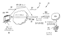
ビデオフォン(15)ネットワーク(40)では、ゲートウェイ(70)は、SIPではない物をSIP環境に接続する。普通、プロトコルの差異に加えて電気的な差異がある。ゲートウェイ(70)の大半は、他の電話又はビデオ会議デバイスを、ビデオフォン(15)のシステム(10)に接続する。
In the
ゲートウェイ(70)は、インターフェイスで区別される。一方の側はネットワーク(40)であり、ビデオフォン(15)では、これはイーサネット又はATMである。外側は、アナログ電話線又はRS−232ポートであろう。ポートのタイプ、番号及び特徴は、あるゲートウェイ(70)を他と区別する。ネットワーク(40)の側には、RTP又はALL2のような転送プロトコルと、SIP、メガコ(Megaco)又はMGCPのような信号伝達プロトコルとがある。
The gateway (70) is distinguished by an interface. One side is the network (40), and for the videophone (15), this is Ethernet or ATM. The outside would be an analog telephone line or an RS-232 port. The port type, number, and characteristics distinguish one gateway (70) from another. On the
外側では、与えられたインターフェイスに応じた多種多様なプロトコルがあってよい。例えば、ISDN(Q.931)又はPOTSシグナリングがあろう。PSTNゲートウェイ(70)は、PSTNラインをビデオフォン(15)システム(10)にその場で接続する。PBXゲートウェイ(70)によって、ビデオフォン(15)システム(10)は、メーカー独自仕様の電話をエミュレートして、その場にあるPBXへの互換性を与える。POTSゲートウェイ(70)は、みすぼらしいアナログフォンをビデオフォン(15)システム(10)に接続する。H.323ゲートウェイ(70)は、H.323システム(10)を、SIPベースのビデオフォン(15)システム(10)に接続する。これは、信号伝達のみのゲートウェイ(70)であり、メディアサーバ(66)は、H.261からMPEGへの変換を行う。
On the outside, there may be a wide variety of protocols depending on a given interface. For example, there may be ISDN (Q.931) or POTS signaling. The PSTN gateway (70) connects the PSTN line to the videophone (15) system (10) on the spot. With the
ビデオフォン(15)で実行可能な3つの技術として、セッション開始プロトコル(SIP)、セッション記述プロトコル(SDP)、リアルタイム転送プロトコル(RTP)があり、これらは全て、引用をもって本明細書の一部となる。
The three technologies that can be implemented on the
SIPは、パケットネットワークに渡る音声及びビデオセッションを初期化し、管理し、終了する信号伝達プロトコルである。 SIP is a signaling protocol that initializes, manages, and terminates voice and video sessions across packet networks.
SDPは、マルチメディアセッションの初期化におけるセッション告知、セッション案内、及びその他のフォームを目的とするマルチメディアセッションを記述する。SIPは、SDPを用いてメディアセッションを記述する。 SDP describes a multimedia session intended for session announcements, session guidance, and other forms of multimedia session initialization. SIP describes a media session using SDP.
RTPは、マルチキャスト又はユニキャストのネットワーク(40)でのサービスに渡って、オーディオ、ビデオ又はシミュレーションデータのようなリアルタイムデータを転送する用途に適しているエンドツーエンドのネットワーク(40)転送機能を与える。SIPは、RTPを用いてメディアセッション伝送を行う。 RTP provides an end-to-end network (40) transfer function that is suitable for applications that transfer real-time data such as audio, video or simulation data across a service in a multicast or unicast network (40). . SIP performs media session transmission using RTP.
ビデオフォン(15)は、如何なる会議ブリッジ又はMCUも用いることなく、3又は4以上のパーティで会議を行える。これは、SIPで定められるようにATMポイントツーマルチポイントストリームを用いて達成される。さらに詳細に述べると、MPEG-2ストリーム及び低フレームレートストリームがパケット化されてネットワーク(40)に転送される場合、各パケットのヘッダ情報は、周知のように、会議の受信ビデオフォン(15)の全てのアドレスを特定する。この情報から、パケットがネットワーク(40)に転送される場合に、SIPは、異なるパケットについて必要な接続を確立して、所望のビデオフォン(15)の送り先にそれらが達することができる。
The
如何なる会議ブリッジも使用しない会議の例として、10個のビデオフォン(15)があって、それらは、会議のパーティがいる別々の場所に配置されているとする。各ビデオフォン(15)は、オーディオベースのストリームと、MPEG-2ベースのストリームと、低フレームレートベースのストリームとを生成する。しかしながら、各ビデオフォン(15)は、これらストリームの何れも自分に送り戻さないので、10のパーティがあるビデオフォン(15)の会議では、各々は、その他9個のビデオフォン(15)と効率的に通信可能となる。一方で、ビデオフォン(15)がそれ自身と通信する場合には、帯域幅を最大限に使用するために、どのビデオフォン(15)で生成されたビデオも、必要ならばビデオフォン(15)で生成されたオーディオも、基本的にそれが他のビデオフォン(15)であるかのように見られ、又は聞かれ得る。しかし、以下で説明するように内部チャンネルを通ると、ネットワーク(40)のどの帯域幅の使用も必要とされない。
As an example of a conference that does not use any conference bridge, there are 10
会議では、各ビデオフォン(15)は、9つのオーディオベースのデータストリームを受信する。3つのMPEG-2ベースのデータストリームと、6つの低フレームレートベースのデータストリームとがある。必要ならば、レシーバは、低フレームレートの9つのストリームを選択して、ディスプレイ(54)は各ビデオフォン(15)の小さい画像を表示し、又は、MPEG-2ベースの4つのストリームを選択して、ディスプレイ(54)は会議の4つのビデオフォン(15)からの画像で満たされる。4つのMPEG-2ベースのデータストリームが表示されるならば、ディスプレイ(54)に表示用の領域はないので、低フレームレートベースのストリームの画像は表示されない。3つのMPEG-2ベースのデータストリームが表示される場合、6つの低フレームレートベースのストリームを表示できる。各ストリームは、いろいろなビデオフォン(15)にて、上述したように作成及び受信される。
In the conference, each
大きな画像を4つより多く会議で表示することが求められるならば、これを達成する方法では、追加のビデオフォン(15)が互いに接続されて、図7に示すように、個々のビデオフォン(15)のディスプレイは、一列に並べられる。あるビデオフォン(15)をマスターとすることができ、追加のビデオフォンが加えられると、それはマスタービデオフォン(15)のスレーブとなる。マスタービデオフォン(15)は、異なっているビデオフォン(15)に渡って、大きい及び小さい画像の表示を制御する。
If it is desired to display more than four large images in a meeting, a method to achieve this is to connect
会議のビデオフォン(15)のディスプレイに、誰が大きい画像として、誰が小さい画像として表示されるかを決定するプロトコルについて、1つの好ましい実施例は、最近の3人の話し手を大きく表示し、その他のパーティを小さく表示するというものである。即ち、現在話をしているパーティと、それ以前の2人の話し手とが大きく表示される。会議の各ビデオフォン(15)は、会議のオーディオベースのストリームの全てを受信するので、各ビデオフォン(15)は、そのメインコントローラ(50)を用いて、所定の瞬間にて話が起こっている場所を割り出し、さらに、ネットワークインターフェイスカード(56)が、話が生じているビデオフォン(15)のMPEG-2ストリームを受け取るが、低フレームレートストリームを受け取らないようにする。別のプロトコルでは、あるビデオフォン(15)は、リード又はモデレータビデオフォン(15)として設定され、リードビデオフォン(15)は、大きい及び小さい画像について、他の全てのビデオフォン(15)が見ているものを選別する。さらに別のプロトコルでは、誰を大きくし、誰を小さくするかという画像の選択は固定されて、会議を通じて同一に維持される。プロトコルは、各ビデオフォン(15)が、受信する画像をそれらがどのように表示するのを欲しているかを調べるというようにできる。MPEG-2ベースのストリーム及び低フレームレートストリームの両方が、ネットワーク(40)上にて、会議の受信ビデオフォンに転送される。その結果、両方のビデオストリームは、各受信ビデオフォン(15)にて利用でき、選択されているディスプレイ(54)のプロトコルに応じて表示される。
For a protocol that determines who is displayed as a large image and who is displayed as a small image on the display of the
各ビデオフォン(15)で転送されるオーディオベースのストリームについては、帯域幅をさらに効果的に使用するために、そして、如何なる送信ビデオフォン(15)又は受信ビデオフォン(15)にてなされる処理要求を減らして、オーディオ処理を補助するために、オーディオベースのストリームは、送信ビデオフォン(15)にて所定のデジベルの閾値を超えたオーディオがある場合にのみ、ビデオフォン(15)で送信される。十分大きな音のオーディオベースのストリームを送信することのみによって、話が生じている場合に達するように又は超えるように閾値が較正されているとの仮定の下、基本的に帯域幅を使う以外に何も貢献しない外部からのバックグラウンドノイズが送受されることが防がれるだけでなく、話のオーディオストリームのみが受信されているので、話に関するMPEG-2ストリームを選択することが助けられる。 For audio-based streams transferred by each videophone (15), in order to make more efficient use of bandwidth and processing done at any transmitting videophone (15) or receiving videophone (15) In order to reduce demand and assist audio processing, audio-based streams are transmitted on the videophone (15) only if there is audio that exceeds the predetermined decibel threshold on the transmitting videophone (15). The Basically other than using bandwidth under the assumption that the threshold is calibrated to reach or exceed when speech is occurring by only transmitting an audio-based stream of loud enough sound Not only is the external background noise that does not contribute anything prevented from being sent and received, but only the audio stream of the story is being received, so it is helpful to select the MPEG-2 stream for the story.
上述のように、特定のビデオフォン(15)が、他のビデオフォン(15)に送られている自分の画像を見たい場合には、FPGA(38)で作成された低フレームレートストリームがビデオフォン(15)のローカルメモリに送られる。しかしながら、低フレームレートストリームが、パケット化されて、ビデオフォン(15)からネットワーク(40)に送られる場合に起こり得るような圧縮は行われない。このローカルメモリから、メインプロセッサは、ソフトウェアを用いてそれを処理して、それをディスプレイ(54)に小さい画像として表示させる。
As mentioned above, if a particular videophone (15) wants to see his image being sent to another videophone (15), the low frame rate stream created by the FPGA (38) Sent to the local memory of the phone (15). However, there is no compression that can occur when a low frame rate stream is packetized and sent from the
さらに、ビデオフォン(15)は、ネットワーク(40)から受信したどのオーディオ又はビデオストリームが聞かれるか又は見られるかを制御する。ビデオフォン(15)のユーザが見たい又は聞きたいよりも多くのパーティが会議にある状況において、ビデオフォン(15)のユーザは、会議全体を構成するオーディオ又はビデオストリームの一部のみを見る又は聞くように選択できる。例えば、パーティが100ある会議では、ユーザは、見ることができる100の画像から全23の画像について、3つのビデオストリームをスクリーン上の大きな画像として、20のビデオストリームをスクリーン上の小さな画像として見ることを選択する。ビデオフォン(15)のユーザは、声の大きな3人の話し手を大きな画像として表示し、また、会議のパーティのタッチスクリーン(74)を介して、小さな画像として表示する20のパーティを選択する。これらパーティは、タッチスクリーンのページにリストアップされている。他のプロトコルを選択できて、小さな画像として表示される20の画像を、会議が始まって各パーティが紹介をした時刻からの、会議における最新の話し手になるようにできる。表示されるビデオストリームの数を制御することで、組織が会議に適合し、ビデオフォン(15)のリソースの使用がより良く割り振られる。
In addition, the
スクリーンで表示される個々の画像について、各画像に関連した選択が可能である。例えば、1つの画像を会議コールのモデレータで選択し、2つの画像を、会議の現時点で最後の/最も声が大きい話し手とし、その他の画像を、その他の会議の参加者全てからユーザが選択した人物とすることができる。このように、会議のあらゆる参加者又はユーザは、会議の参加者の全数から画像の様々な選択ができるであろう。そして、必要とされる最大帯域幅は、会議の参加者の数に拘わらず、1つのビデオストリームをネットワークに送るためのものとなり、4つのビデオストリームをネットワークから受け取るためのものとなる。 For individual images displayed on the screen, selections associated with each image are possible. For example, one image was selected by the conference call moderator, two images were the last / loudest speaker at the time of the conference, and the other images were selected by the user from all other conference participants. It can be a person. In this way, any conference participant or user will be able to make various selections of images from the total number of conference participants. The maximum bandwidth required is for sending one video stream to the network and receiving four video streams from the network, regardless of the number of participants in the conference.
オーディオストリームに関して、最も声の大きい3人の話し手の各々の画像がスクリーンに表示される間は、それらの話し手のオーディオストリームのみが選択されて聞かれる制限をビデオフォン(15)に課すことができる。DSP(62)は、受信したオーディオストリームを解析して、声が最も大きい話し手の3つのオーディオストリームのみを再生させて、同時に、声が最も大きい話し手の3つのオーディオストリームに関係した、大きな画像の第1ビデオストリームのみを受信するようにネットワークインターフェイス(42)に指示する。一般的には、大勢の人々が同時に話すと、混乱が増加して、理解が妨げられる。故に、ユーザによる制御がオーディオストリームに行われることで、組織のある程度にそれらを認識させることが可能となる。
With respect to the audio stream, while the images of each of the three loudest speakers are displayed on the screen, it is possible to impose restrictions on the
オーディオストリームの制御の一環として、上述のように、各ビデオフォン(15)は、そのビデオフォン(15)のノイズが閾値を超えた場合にのみ、オーディオストリームを送る。好ましくは、閾値は動的であって、所定の時刻における、声の大きな3人の話し手に関連した音の大きな3つのオーディオストリームのノイズレベルに基づいている。このため、オーディオストリームが声の大きな3人の話し手のオーディオストリームの一つとして認められるので、その他のオーディオストリームのノイズレベルは、モニタされて、特定される必要がある。DSP(62)は、ネットワーク(40)を介してネットワークインターフェイス(42)から送られるオーディオストリームを受信する。そして、DSP(62)は、オーディオストリームを調べて、最も大きなノイズを有する3つのストリームを特定し、最も声の大きい3人の話し手のものとして特定されている受信した3つのオーディオストリームのノイズレベルを、ビデオフォン(15)のシーンのノイズレベルと比較する。ビデオフォン(15)のシーンのノイズレベルが、受信したどのオーディオストリームよりも大きい場合、ビデオフォン(15)は、そのオーディオストリームをネットワーク(40)に送る。DSP(62)によるこのような解析が、会議の各ビデオフォンで独立に行われて、会議に渡って分散した解析が行われる。各ビデオフォンは、その他の全てのビデオフォンと独立して、受信したオーディオストリームに関する解析を自ら行う。明らかに、これらオーディオストリームは、所定の時間にて声の大きい3人の話し手の1人のものであると十分に保証できるほどシーンのノイズが大きいと、個々のビデオフォン(15)が判別した後にのみ、各ビデオフォン(15)によって送られる。各ビデオフォン(15)は その結果、受信したオーディオストリームの情報を得て、それを自己のノイズレベルとの比較の基礎として用いる。そして、各ビデオフォン(15)は、独自に閾値の決定を行っている。
As part of controlling the audio stream, as described above, each videophone (15) sends an audio stream only if the noise of that videophone (15) exceeds a threshold. Preferably, the threshold is dynamic and is based on the noise level of three loud audio streams associated with three loud speakers at a given time. For this reason, since the audio stream is recognized as one of the audio streams of three loud speakers, the noise levels of the other audio streams need to be monitored and identified. The DSP (62) receives an audio stream sent from the network interface (42) via the network (40). The DSP (62) then examines the audio stream, identifies the three streams with the highest noise, and the noise levels of the three received audio streams identified as those of the three loudest speakers. Is compared with the noise level of the scene of the videophone (15). If the noise level of the
分散した解析を行う別の方法では、各ビデオフォンが、DSP(62)にて用いられるべき閾値となるものを決定した後、会議の他の全てのビデオフォンにこの閾値が送られる。これにより、全てのビデオフォンは、他の全てのビデオフォンが閾値としたものを検討でき、例えば、それらの閾値を平均して、そのビデオフォンのシーンに適用される閾値を特定する。
Another way of performing distributed analysis is that after each videophone has determined what is the threshold to be used in the
声が最も大きい3人の話し手のビデオストリームを選択する技術を用いることで、パーティが大きな声で一度に話し始めて、混乱と不理解が生じる瞬間があるかも知れない。しかしながら、そのようにすることで、それはノイズを閾値のレベルに上げて、非常に短い間に、他と同程度の大きさのノイズを生成していないオーディオストリームは除去されて、声の最も大きな3人の話し手のオーディオストリームのみが再度選択されて聞こえるであろう。また、その他のオーディオストリームは選択されておらず、これらオーディオストリームが寄与しているかも知れないノイズのある程度が取り除かれる。このことは、時に、3つを超えるオーディオストリームがビデオフォン(15)で受信されることを意味している。3個を超えるビデオフォンで、ある瞬間にノイズが閾値を超えて、このようなビデオフォンの各々が、その時にオーディオストリームを生成してネットワーク(40)に送り得るからである。しかしながら、今し方説明したように、一旦閾値が変更されると、事態は終わるだろう。オーディオストリームに関したこの分散した解析は、ここで説明したビデオフォン(15)に限定されることはなく、ビデオストリームの有無に拘わらず、如何なるタイプの音声を用いた会議でも利用可能である。
Using technology to select the video stream of the three speakers with the loudest voices, there may be moments when the party starts speaking loudly at once, causing confusion and unintelligibility. However, in doing so, it raises the noise to a threshold level, and in a very short time the audio stream that is not producing as much noise as the other is removed, and the loudest voice Only the audio stream of the three speakers will be selected and heard again. Also, the other audio streams are not selected and some of the noise that these audio streams may contribute is removed. This means that sometimes more than three audio streams are received at the videophone (15). This is because with more than three videophones, noise exceeds a threshold at a moment, and each such videophone can then generate an audio stream and send it to the network (40). However, as explained here, once the threshold is changed, the situation will end. This distributed analysis of audio streams is not limited to the
使用する帯域幅の節約を重要視しており、必要なもののみを送って帯域幅を節約することから、画像のクリップは、受信ビデオフォン(15)ではなくエンコーダ(36)にて行われる。送信ビデオフォン(15)が、それの画像が受信ビデオフォン(15)にてどのように現れるかを知っている場合、エンコーダ(36)は、シーンの大きな画像を、それが送信される前にクリップする。そして、画像のそれほど大きくない部分が送信されて、帯域幅を使用する。クリップが受信ビデオフォン(15)で起こる場合、ソフトウエアを伴ったメインプロセッサは、受信した画像がディスプレイコントローラ(52)に供給される前に、それを処理するであろう。 The importance of saving bandwidth to be used is important, and since only necessary items are sent to save bandwidth, image clipping is performed by the encoder (36) instead of the receiving videophone (15). If the transmitting videophone (15) knows how its image will appear on the receiving videophone (15), the encoder (36) will send a large image of the scene before it is transmitted. Clip. Then, a not-so-large part of the image is transmitted and uses bandwidth. If the clip occurs on the receiving videophone (15), the main processor with software will process it before the received image is fed to the display controller (52).
第2カメラをビデオフォン(15)に接続すると、シーンの別の眺めが得られる。例えば、部屋では、第1カメラ、即ち主カメラが、視聴者又は話し手の顔に焦点を合わせて配置される。しかしながら、部屋にはさらに人がいて、ビデオフォン(15)を制御する人は、受信ビデオフォン(15)の他の視聴者を見たいと欲する。例えば、第2カメラは、部屋の上隅に配置されて、主カメラよりも基本的に部屋のかなり広い領域を見る。第2カメラの出力はデコーダ(34)に与えられる。デコーダ(34)は、ビデオ出力を受け取る幾つかのポートを有している。または、第2カメラから送られるストリームが既にデジタル化されている場合、それは、主カメラと同様なチャンネルを通じて、ビデオフォン(15)の処理要素に与えられる。各ビデオフォン(15)は、その外に送られるものは何でも制御し、送信するカメラ出力の選択は、ビデオフォン(15)を制御する視聴者によってなされるのが好ましい。一方で、あるビデオフォン(15)のカメラから送信されるストリームを制御及び選択する能力を、離れた受信ビデオフォン(15)に与えることができる。制御ビデオフォン(15)からの制御信号は、ネットワーク(40)を通じて送信されて、送信用に選択されたストリームを与える個々のビデオフォン(15)にて受信される。第2カメラに加えて、DVD、VCR又はホワイトボードカメラのビデオ出力のような、その他のタイプの如何なるビデオ出力も、ビデオフォン(15)を通じて供給されてよい。
When the second camera is connected to the
好ましい実施例では、ビデオフォン(15)はピークモードで動作する。ピークモードでは、ビデオフォン(15)のカメラは、前方のシーンのスチル画像を取得して、この画像を受信すると予め決めている他のビデオフォン(15)に送信する。例えば、スピードダイアルメニュに、このようなビデオフォン(15)のリストがある。または、ピークモードでは、得られたスチル画像がビデオフォン(15)で保持されて、要求に応じて、そのビデオフォン(15)にコールしたいと思っている者に供給される。理想的には、ビデオフォン(15)の好ましい使用形態に合致するように、ビデオフォン(15)のユーザは、ビデオフォン(15)の外へ送られるものを全て制御して、単に、ピークモードをオフにすることを選択し、又はどの画像が送られるかを制御する。アクティブコールが起こると、ピークモードはオフになって、ピークモードと、連続的な画像ストリームがカメラで得られるアクティブコールとの間で矛盾が生じない。ピークモードでは、所定の時間間隔で、例えば、1分、5分、30分間隔等で、シーンのスチル画像が得られる。ピークモードでは、スチル画像が得られる前の所定の時間にて、例えば、画像が得られる5又は10秒前にて、オーディオキューが示されて、まさに画像が撮られようとしており、見苦しくないようにすべき旨の警告が、カメラの前にいる者に与えられる。オーディオキューは、ビープ音、ピング(ping)音、若しくはその他の録音されたノイズ、又はメッセージとすることができる。このように、ピークモードが用いられる場合には、ビデオフォン(15)のカメラの前におけるシーンのピークが他のビデオフォン(15)で利用可能となり、その他のビデオフォン(15)に、カメラに関わる人物の存在が示される。
In the preferred embodiment, the
プレセンスセンサの別の実施例では、カメラの前の領域に対するカメラの自動レンズの位置を、プレゼンスセンサとして働かせる。カメラの前に人がいない場合、カメラの自動レンズは、その領域内の物体又は壁に焦点を当てる。人物がカメラの前にいる場合、自動レンズはその人物に焦点を当てる。人物によって、人物がレンズの前にいない場合と異なる位置にレンズが配置される。レンズの焦点を表示するカメラの信号は、カメラからFPGA(38)に送られる。FPGA(38)は、その後、例えば、送信ビデオフォン(15)のスピードダイヤルリストにあるビデオフォン(15)の受信側のような、所定のリストにあるビデオフォン(15)の受信側に焦点の情報を送る。これによって、視聴者がビデオフォン(15)の前にいるか否かが受信ビデオフォン(15)に知らされて、誰がいることが示される。
In another embodiment of the pre-sense sensor, the position of the camera's automatic lens relative to the area in front of the camera serves as a presence sensor. If there is no person in front of the camera, the camera's automatic lens focuses on an object or wall in that area. If a person is in front of the camera, the auto lens will focus on that person. Depending on the person, the lens is arranged at a different position from the case where the person is not in front of the lens. The camera signal indicating the focus of the lens is sent from the camera to the FPGA (38). The FPGA (38) is then focused on the receiver of a videophone (15) in a predetermined list, such as the receiver of a videophone (15) in the speed dial list of the transmitting videophone (15). Send information. This informs the receiving
また、ビデオフォン(15)はビデオメールを提供する。あるビデオコール(15)から別のビデオフォン(15)へのビデオコールが試みられて、所定時間後に、例えば4回ベルが鳴った後に、受信ビデオフォン(15)がビデオコールに応答しない場合、受信ビデオフォン(15)に関連したビデオサーバ(66)がビデオコールに応答する。ビデオサーバ(66)は、送信ビデオフォン(15)から送られるビデオコールに応答し、送信ビデオフォン(15)に、記録されたオーディオメッセージを、又は、記録されたビデオ画像を伴ったオーディオメッセージを送る。これらメッセージは、応答しない受信ビデオフォン(15)から送られて、前もってビデオサーバ(66)に記録されている。ビデオサーバ(66)は、メッセージを再生して、電話をかける人に、オーディオ、又はオーディオ及びビデオキューを与えて、ビープ音のような所定の表示の後にメッセージを残す。所定の表示が起こると、電話をかける人は、その人のビデオ画像に加えて発言を含んだメッセージを残す。ビデオ及びオーディオメッセージは、ビデオサーバ(66)にてメモリに格納される。メッセージは、必要なだけ長くでき、又は、定められた所定の時間間隔に限定できる。所定の時間間隔が経過した後、又は、電話をかける人がコールを済ませて終了した後、ビデオサーバ(66)は、ビデオメッセージを保存して、最初のコールに応答しなかった受信ビデオフォン(15)に信号を送る。受信ビデオフォン(15)の視聴者は、ビデオメッセージを待っている。このメッセージはテキスト若しくは、受信ビデオフォン(15)のディスプレイ(54)に表示されるビデオ画像とすることができ、または、単に、メッセージライトとすることもできる。メッセージライトが点灯すると、受信ビデオフォン(15)の視聴者に、視聴者へのビデオメールがある旨が知らされる。
The
視聴者がビデオメールを見ることを希望する場合、視聴者は、単にタッチスクリーン(74)の領域を選択するだけで、ビデオメールを起動できる。ユーザには、ビデオメールの読み出しを含めた、メールに関する一連の操作オプションが示される。メールの読み出しでは、信号がビデオサーバ(66)に送られて、ビデオフォン(15)のディスプレイ(54)にて視聴者用にビデオメールが再生される。画像のストリームがビデオサーバ(66)から送られて、ビデオベースのストリーム用の上述の経路を通じて受信ビデオフォン(15)に向かい、それを介して表示される。ビデオフォン(15)の視聴者が、ビデオサーバ(66)にメッセージを記録して、視聴者がビデオコールに答えない場合にビデオコールに応答するためには、視聴者はタッチスクリーン(74)の領域にタッチして、ビデオサーバ(66)を動作させる。視聴者は、所定の時間に、オーディオ又はオーディオ及びビデオのメッセージを記録するように促される。視聴者がこれを行うと、メッセージが作成される。
If the viewer wishes to view the video mail, the viewer can activate the video mail simply by selecting an area on the
ビデオフォン(15)は、ユーザがボリューム調整することなく、所定のレベルでスピーカを動作させる。ビデオフォン(15)のスピーカ(64)は、マイクロホンでキャリブレーションできるので、マイクロフォンが非常に大きいノイズを拾う場合には、メインコントローラ(50)及びDSP(62)は、スピーカ(64)のオーディオ出力のレベルを下げて、ノイズレベルを低減する。所定且つ所望のレベルを設定することで、ビデオフォン(15)は、視聴者が何かを行うことなく、自動的にボリュームの大きさを制御する。
The videophone (15) operates the speaker at a predetermined level without the user adjusting the volume. The speaker (64) of the videophone (15) can be calibrated with a microphone, so if the microphone picks up very loud noise, the main controller (50) and DSP (62) will output the audio output of the speaker (64). Reduce the noise level to reduce the noise level. By setting a predetermined and desired level, the
ビデオフォン(15)は、特定の人物に話しかける問合せを認識すると、受信ビデオフォン(15)でのトーン又は信号のような、認識に用いられる所定のスピーチパターンを用いて、受信ビデオフォン(15)にコールが要求されている旨を、受信ビデオフォン(15)の視聴者に知らせるようにプログラムできる。例えば、言葉「ヘイ、クレイグ(Hey Craig)」がビデオフォン(15)で用いられて、コールがクレイグに向けて開始されるべきものであることが送信ビデオフォン(15)で認識される。視聴者が「ヘイ、クレイグ」を言うことで、送信ビデオフォンが自動的にクレイグへのコールを開始し、言葉「ヘイ、クレイグ」がクレイグの受信ビデオフォン(15)に送られる。クレイグの受信ビデオフォン(15)が鳴って、コールがクレイグに要求されていることを示す代わりに、言葉「ヘイ、クレイグ」が、直ちにクレイグのビデオフォン(15)にアナウンスされる。これは、クレイグの注意を喚起するために通常起こされるベルに置き換わる。この動作を行う機能は、メインコントローラ(50)及びDSP(62)で実現されるであろう。発言「ヘイ、クレイグ」は、視聴者によってアナウンスされて、上述のようにサーバ(66)に送信される。サーバ(66)は、発言を解析して、命令として言葉を認識し、命令に記されたパーティにコールを開始する。その後、サーバ(66)は、クレイグのビデオフォン(15)のアドレス情報を用いて、クレイグのビデオフォン(15)とコールを開始し、クレイグのビデオフォン(15)で「ヘイ、クレイグ」になる信号又は音色を発生させる。
When the videophone (15) recognizes a query to speak to a particular person, the videophone (15) uses a predetermined speech pattern used for recognition, such as a tone or signal at the videophone (15). Can be programmed to inform the viewer of the receiving
当該技術分野で周知のように、エンコーダ(36)は、各フレームの最初及び最後を特定できる。エンコーダ(36)がデータを受信すると、それはフレームのデータをエンコードして、フレームが完全になるまで格納する。エンコーダ(36)が使用するアルゴリズムによって、格納されたフレームは、次のフレームを形成するための基礎として用いられる。格納されたフレームは、次のフレームをエンコードするためのリファレンスフレームとして働く。これは、基本的に、最初からのフレーム全部ではなく、あるフレームから次のフレームへのフレームの変化がエンコードの中心だからである。その後、エンコードされたフレームは、上述のように、直ちに送り出されて、パケット化される。フレームは、パケット化を除いてバッファリングされることはないので、遅延は最小限に抑えられる。なお、エンコーダ(36)がフレームのデータをエンコードする際に、データの送信速度をさらに速くするために、フレーム全体がエンコードされることを待たないで、エンコードされたデータをパケット化のために順序付けしてもよい。また、先に説明した理由から、エンコードされたデータは、フレームを形成するために格納されるので、リファレンスフレームがフレームで利用可能となる。しかしながら、別個に、データは、エンコードされる際にパケット化のために送られて、パケット化の準備中にフレームを形成する。しかし、パケットが送信可能となって、フレームの一部分のみがパケットを部分的に構成する場合であっても、フレームの残りの部分が別個のパケットとして送信されて、フレーム情報を伴う両方のパケットが受信ビデオフォン(15)で受信されるまで、フレームは形成されない。
As is well known in the art, the
図1を参照すると、ビデオフォン(15)がネットワーク(40)に接続されている。ビデオフォン(15)は、銅又はマルチモードファイバーの何れかの上にて、10/100イーサネット接続と、オプションとしてATM155Mbps接続とをサポートしている。各ビデオフォン(15)端末は、通常、ユーザのPC(68)に取り付けられている。ビデオフォン(15)の役割は、(会議)コールのオーディオ及びビデオ特性を与えることである。PC(68)は、その他の機能に用いられる。ビデオフォン(15)を用いてコールを確立することで、PC(68)間のマイクロソフトネットミーティングセッションが確立される。これによって、ユーザは、ウインドウズベースのプログラム、例えば、パワーポイントプレゼンテーションやスプレッドシートと協動すること、電子ホワイトボードと画像を交換すること、ファイルを転送すること、テキストベースのチャットプログラムを使用すること等が行える。ビデオフォン(15)端末がどのように接続されているかに拘わりなく、PC(68)は、イーサネットに接続できる。PC(68)は、当然に、ATM LANにも接続できる。PC(68)と、関連する送信ビデオフォン(15)とは、ネットワーク(40)を通じて相互に通信する。PC(68)と、関連する送信ビデオフォン(15)とが相互に通信することで、PC(68)は、送信ビデオフォン(15)が話している相手を知る。その後、PC(68)は、送信ビデオフォン(15)が話している相手である受信ビデオフォン(15)のPC(68)と通信可能となる。また、PC(68)は、ビデオフォン(15)にコールすることも可能である。
Referring to FIG. 1, a
システム(10)の機能の大半は、サーバーベースであって、ビデオフォン(15)のプロキシサーバで動作するソフトウエアで実現されている。プロキシサーバは、SIPプロキシサーバであるのが好ましい。基本機能をもたらすために第1サーバが必要とされ、第2サーバは、弾力的な動作に、言い換えると、第1サーバが失敗したイベントを保全するサービスに必要とされる。このような場合、サーバとビデオフォン(15)のソフトウエアは、バックアップサーバ(66)に自動的にスワップする。この構成を用いて、ネットワーク(40)上の他のビデオフォン(15)に、さらに、好ましくはSIPフォンであるネットワークに登録された電話に、ビデオフォン(15)はコールをすることが可能となり、また、これらからのコールを受け取ることが可能となる。
Most of the functions of the system (10) are server-based, and are realized by software that operates on the proxy server of the videophone (15). The proxy server is preferably a SIP proxy server. A first server is required to provide basic functionality, and a second server is required for elastic operation, in other words, a service that preserves events in which the first server has failed. In such a case, the software of the server and the
メディアサーバは、一連のメディアストリーム上のユーザに一連のサービスを提供する。メディアサーバ(66)は、主サーバ(feature server)で(好ましくは主サーバで)制御される。それは、ユーザインボキャブル(user-invocable)な種々の機能の一部として、メディアストリームの送信側と受信側を与えるために用いられる。メディアサーバで与えられるサービスは、会議ブリッジ、記録及び再生、トランスコーディング、音色及びアナウンスメントである。
The media server provides a series of services to users on a series of media streams. The
メディアサーバ(66)は、LAN又はWAN上にあるボックスである。通常、それは、その他の接続を有していない。それは、SIPデバイスであるのが好ましい。主サーバは、ビデオフォン(15)端末から発する信号経路内にある。しかしながら、メディアの経路は、メディアサーバ(66)から装置に直通するだろう。
The
動作中、ユーザは、ビデオメール等の機能を要求してよい。主サーバ(66)は、ユーザインターフェイス及びシグナリング機能を与え、メディアサーバ(66)は、(使用されるならば)マルチメディアプロンプト(multimedia prompt)機能と、メッセージの記録再生機能を与えるだろう。
In operation, the user may request a function such as video mail. The
ビデオフォン(15)端末が、(SIPビデオフォンのような)プロトコル外又は基準外の(ビデオ)フォンにコールをし、又はそれらのコールを受け入れることを可能にするために、SIPゲートウェイのようなゲートウェイ(70)が加えられる。4本のアナログラインを有するゲートウェイ(70)が、PSTNに直接接続されるか、ローカルPBXのアナログラインに接続される。出力ラインを供給する通常の規則が適用される。一般的な1本の中継ラインが6人のユーザの全てに供給される。つまり、どのユーザも自分のフォンを用いて、勤務時間外の10分間、外部接続にダイヤルすると仮定する。ビデオフォン(15)端末が現在のPBXの拡張として働く場合、着信コールに関する限り、1本のアナログラインが各ビデオフォン(15)に必要となる。
To allow a videophone (15) terminal to call or accept a non-protocol or non-standard (video) phone (such as a SIP videophone), such as a SIP gateway A gateway (70) is added. A
CNNのようなTVソースが、ビデオフォン(15)のユーザに利用され得る。ビデオフォン(15)のビデオサーバ(66)によって、このサービスが可能となる。サーバ(66)は、1つのビデオチャンネルとの接続をサポートし、そのチャンネルは、ネットワーク(40)上のどのビデオフォン(15)のユーザでも利用される。ビデオチャンネルは、通常の2つの会議セッションと同等である。チューナは、利用可能なチャンネルをセットする。新たなビデオフォン(15)のビデオサーバ(66)が、ユーザが同時利用を願う異なるチャンネルの各々について設定に加えられる。
A TV source such as CNN can be utilized by the
また、ビデオフォン(15)のサーバ(66)(好ましくはSIP)は、ユーザデータのデータベースを持っており、ユーザコンタクト情報のローカルキャッシュを含んでいる。このデータべースは、ユーザに関するメインコンタクトデータべースと同期化できる。同期化は、例えば、アウトルック/エクスチェンジのユーザによって、ロータスノーツのユーザのために行われる。別個のプログラムが、NTベースの如何なるサーバ(66)プラットホームでも動作して、同期化を行う。扱うサイトの数に拘わらず、1つのサーバのみが必要とされる。
The server (66) (preferably SIP) of the
図2に示すように、通常、ビデオフォン(15)端末は、幾つかのサイトに渡って分散しており、ワイドエリアネットワーク(40)と協力する。あるサーバ(66)は、1つのキャンパスにて、最大で100個以上のビデオフォン(15)を十分に扱える。サイト上のビデオフォン(15)の数が増加すると、ある段階でさらにサーバをインストールする必要が生じる。
As shown in FIG. 2,
ビデオフォン(15)が幾つかのサイトを渡って分散すると、中央サーバに基づいてそれらを動作可能となるが、WANで使用される帯域幅と、WANへの依存とを考慮すると、これは勧められる構成ではない。好ましくは、各サイトは少なくとも1つのサーバ(66)を有しており、該サーバ(66)は、SIPが用いられる場合、SIPサーバ(66)であるのが好ましい。さらに忠告すると、最も簡単で容易な構成は各サイトが、好ましくはSIPである二重のサーバを有することである。しかしながら、遠隔のサイトサーバの代わりとして、中央サーバを用いることも可能である。 If videophones (15) are distributed across several sites, they will be able to operate based on a central server, but this is recommended considering the bandwidth used by the WAN and its dependence on the WAN. Is not configured. Preferably, each site has at least one server (66), which is preferably a SIP server (66) when SIP is used. Further advice is that the simplest and easiest configuration is that each site has a dual server, preferably SIP. However, a central server can be used instead of a remote site server.
ビデオフォン(15)は、ネットワーク(40)の何処においても、1つの中央ゲートウェイ(70)からPSTN又はPBXベースの送信コールが可能である。しかしながら、ビデオフォン(15)が、受信コールを受け入れるためにローカルPBXの延長でもなければならない場合には、PSTNゲートウェイ(70)は、各場所に与えられることが必要である。そのサイトの全てのビデオフォン(15)について、ゲートウェイ(70)のポートが必要となる。
The
中央CNNサーバ(66)は、ネットワーク(40)上のどのビデオフォン(15)にも、TVチャンネルを配信する。それにも拘わらず、WANに渡ってその帯域幅を得るよりは、サイト特有のサーバを含むことが好ましいであろう。
The
ビデオフォン(15)は、(ファイバーと銅のオプションを用いて)10/100イーサネットネットワーク(40)又は155Mbits/sec のATMネットワーク(40)の何れか一方に接続できる。ATMに接続されたビデオフォン(15)は、IPコントロールプレーンを用いて、コールのエンドポイントのATMアドレスを定めて、そして、ATM信号を発して、エンドポイント間で搬送チャンネル(bearer channel)を確立する。搬送チャンネルは、スイッチドバーチャル回路(SVC)で確立され、完全なQoSの要求が特定される。
The
各ビデオストリームは、セッティングと帯域幅のネゴシエーションによって定められるように、2Mbpsと6Mbpsの間で双方向に送信可能である。ディスプレイ手段が2以上のビデオストリームを表示できるので、各ビデオフォンを全接続するのに要求される帯域幅は、コールのパーティ数と共に増加する。送信端のクリップによって、要求される最大の帯域幅は、単一のビデオストリームで使用される帯域幅の約2.5倍となる。サイトに幾つかのビデオフォン(15)がある場合、ユーザとトランク(trunk)間の通常のテレフォンレシオ(telephone ratio)が、ビデオフォン(15)のセッションに加わる。言い換えると、ビデオフォン(15)のユーザは、各コールにて平均して2人の他人と、つまり2つのストリームで会話すると予想され、ユーザは、その時に平均して10分間ビデオフォン(15)を用いる。平均エンコードレートが3Mbpsである場合、このことより、6MbpsのWANの帯域幅が必要となり、この帯域幅では、最大6人までのユーザをサポートすることが期待される。
Each video stream can be transmitted bi-directionally between 2 Mbps and 6 Mbps, as determined by setting and bandwidth negotiation. Since the display means can display more than one video stream, the bandwidth required to fully connect each videophone increases with the number of parties in the call. With the clip at the sending end, the maximum bandwidth required is approximately 2.5 times the bandwidth used in a single video stream. If the site has
図3に示すように、ビデオフォン(15)は、ビデオフォン(15)端末の密度が低い場合に、「p」で動作可能な('p' enabled)イーサネットネットワーク(40)で動作する。ビデオフォン(15)のシステム(10)は、2個のビデオフォン(15)を互いにリンクするネットワーク(40)のATM部分に渡ってSVCを確立すると共に、「p」で動作可能なイーサネットを用いることで、十分なクオリティオブサービスが接続のイーサネット部分に渡って与えられることを保証する。
As shown in FIG. 3, the
ビデオフォン(15)のシステム(10)の基本的な構成要素が、図4に示されている。それらは共にマルチメディア協動ツールを生成して、それらツールは、地理的に分散したチームが交流する能力を増進させる。このようなチームは、ほとんど全ての大企業で存在しており、次第に増加している。さらに、彼らが効果的及び効率的に働くことを助けるツールは、10年前からほとんど変わっておらず、多くの面で不満足なものである。ビデオフォン(15)は、包括的な方法を用いて現存するシステムの多くの問題に対処し、遠隔地間の共同作業に断続的な(discontinuous)改善をもたらす。それは、新たに利用可能な技術を用いて可能となり、クオリティオブサービスと正しいミキシング機能で差別化され、優れたユーザインターフェイスの開発によって使用可能となり、標準ベースのアーキテクチャを用いることで、拡張可能なように設計される。
The basic components of the
オーディオ及びビデオストリームは、上述のように、例えば、周知のSIP技術を用いて、ネットワーク上の始端ビデオフォン(15)から終端ビデオフォン(15)に送信される。SIPメッセージは、異種のネットワークに渡ってIPルーティング技術を用いてルーティングされてよい。異種のネットワークのメディアストリームには、より直接的な経路が要求される。好ましくは、図15に示すように、会議の始端ビデオフォン(15)がイーサネットに接続されて、会議の終端ビデオフォン(15)がATMネットワークに接続されている場合、始端及び終端ビデオフォン間のネットワークを渡るパケットについて、以下に述べるアドレッシングが起こる。始端ビデオフォン(15)は、パケットをイーサネットに送って、始端ビデオフォンのIPアドレスを用いて通信が行われる。パケットは、イーサネットをATMネットワークにリンクする始端ゲートウェイ(80)に到達する。始端ゲートウェイ(80)では、始端ビデオフォン(15)のIPアドレスが、パケットから保存される。始端ゲートウェイ(80)は、始端ゲートウェイ(80)のATMアドレスをパケットに加えて、終端ビデオフォン(15)にパケットを送る。終端ビデオフォン(15)がパケットを受信すると、それは、始端ゲートウェイ(80)のATMアドレスをパケットより格納して、始端ゲートウェイ(80)にリターンパケットを送り返す。リターンパケットは、終端ビデオフォン(15)がパケットを受信したことを示しており、終端ビデオフォン(15)のATMアドレスを伴っている。始端ゲートウェイ(80)は、リターンパケットを受信すると、終端ビデオフォン(15)のATMアドレスを保存し、始端ゲートウェイ(80)のIPアドレスをリターンパケットに加える。リターンパケットは、その後、始端ゲートウェイ(80)から始端ビデオフォン(15)に送り返される。
As described above, the audio and video streams are transmitted from the
このように、始端ビデオフォン(15)と終端ビデオフォン(15)間の経路全体に渡るクリティカルなノード、始端ビデオフォン(15)及び終端ビデオフォン(15)の具体的アドレスが、経路のクリティカルなノードの各々で知られる。最低でも、経路の各ノードは、経路の次のノードのアドレスを知る。必要ならば、個々のパケットが経路に沿って動くにつれて、追加されたアドレスがそれらに保存されて、経路の各ノードは、パケットが向かう次のノードよりも、クリティカルなノードのアドレスについてより多くを知る。これは、パケットがノードからノードへ移動すると、具体的な例としては、始端ビデオフォン(15)から始端ゲートウェイ(80)に、それから終端ビデオフォン(15)に、そして、終端ビデオフォン(15)から始端ゲートウェイ(80)に、それから始端ビデオフォン(15)に戻るように、パケットが移動すると、各ノードは、受け取った個々のパケットを送った前のノードのクリティカルなアドレスを保存し、次のノードが含まれるネットワークのタイプに関した自己のアドレスを持ち込むことによる。その結果として、各ノードが次のノードにパケットを送るのに必要なクリティカルなアドレスは、経路を通じて配布される。 In this way, the critical nodes of the entire path between the start videophone (15) and the end videophone (15), the specific addresses of the start videophone (15) and the end videophone (15) are Known by each of the nodes. At a minimum, each node in the path knows the address of the next node in the path. If necessary, as individual packets move along the path, the added addresses are stored in them so that each node in the path does more about the address of the critical node than the next node to which the packet goes. know. This is because when a packet moves from node to node, a specific example is that the beginning videophone (15), the beginning gateway (80), then the termination videophone (15), and then the termination videophone (15) When a packet moves from one to the beginning gateway (80) and back to the beginning videophone (15), each node stores the critical address of the previous node that sent the individual packet received and By bringing your own address regarding the type of network the node is in. As a result, the critical addresses required for each node to send a packet to the next node are distributed over the path.
イーサネット上の始端ビデオフォン(15)からATMネットワーク上の終端ビデオフォン(15)にパケットを転送するこの例は、逆の場合、つまり、始端端末つまり始端ビデオフォン(15)がATMネットワークと通信し、終端ビデオフォン(15)がイーサネットと通信する場合にも適用できる。
This example of transferring a packet from the start videophone (15) on the Ethernet to the end videophone (15) on the ATM network is the reverse case, that is, the start terminal or the start videophone (15) communicates with the ATM network. This can also be applied to the case where the
同様にして、経路は、イーサネットと通信する始端ビデオフォン(15)と、イーサネットと通信する終端ビデオフォン(15)とを含み、図16に示すように、パケットが行き来するATMネットワークが中間にあるように構成され得る。このような場合、各端に配置された2つのゲートウェイがあって、それらは、イーサネットとATMネットワークのインターフェイスとなる。先述のように、処理では、追加ノードが単純に経路に加えられる。始端ゲートウェイ(80)は、自己のATMアドレスをパケットに取り込んで、それを終端ゲートウェイ(82)に送る。終端ゲートウェイ(82)は、始端ゲートウェイのATMアドレスを保存し、終端ゲートウェイのIPアドレスをパケットに加えて、イーサネット上で終端ビデオフォン(15)に送る。リターンパケットについて、同じ事が逆に起こる。各ゲートウェイは、先のゲートウェイ又は終端ビデオフォン(15)から得た個々のアドレス情報を保存して、自己のアドレスをリターンパケットに加える。リターンパケットは、最終的に始端ビデオフォン(15)に送られる。始端ゲートウェイ(80)及び始端ビデオフォン(15)は、終端ゲートウェイ(82)又は始端ゲートウェイ(80)のATMアドレスを夫々保存し、経路に渡る各リンクにおける個々のアドレスが、より効率的に格納されて、接続のパケットは、迅速に順次転送される。
Similarly, the path includes a starting videophone (15) communicating with Ethernet and a terminating videophone (15) communicating with Ethernet, and an ATM network through which packets come and go is in the middle as shown in FIG. Can be configured as follows. In such a case, there are two gateways located at each end, which are the Ethernet and ATM network interfaces. As mentioned above, the process simply adds additional nodes to the path. The start gateway (80) takes its ATM address into a packet and sends it to the end gateway (82). The terminating
例えば、SIPルーティング情報(または、標準的なルーティング情報であれば何でも用いられる)をパケットに収納するという、当業者に周知の技術と同様な技術を用いて、ビデオフォン(15)のメインコントローラ(50)及びネットワークインターフェイス(42)は、ビデオフォン(15)のアドレスを、それがネットワーク(40)に送る各パケットに加える。また、ネットワークインターフェイス(42)は、ネットワーク上のノードから送られるパケットから受け取ったアドレス情報を、ローカルメモリに格納する。同じように、ネットワーク(40)のゲートウェイについて同様な構成が適用される。周知のように、ゲートウェイは、パケットをその最終的な送り先に移動させる制御手段及びデータ処理手段を有している。ゲートウェイの制御機構のネットワークインターフェイス(42)及びメインコントローラ(50)は、SIPルーティング情報に関した周知の技術で動作し、パケットから受け取ったアドレス情報を格納し、パケットを送ろうとしているネットワーク(40)につ関する自己のアドレス情報をパケットに収納する。例えば、ゲートウェイ又はビデオフォン(15)のアドレス情報は、パケットのヘッダー部のフィールドに配置される。実施例では、終端及び始端ソースとしてビデオフォン(15)が使用されているが、パケットを生成及び受信するデバイスであればどのようなタイプも、このスキーム全体にて使用されることに留意すべきである。
For example, using a technique similar to a technique well known to those skilled in the art of storing SIP routing information (or whatever standard routing information is used) in a packet, the main controller ( 50) and the network interface (42) add the address of the videophone (15) to each packet it sends to the network (40). The network interface (42) stores the address information received from the packet sent from the node on the network in the local memory. Similarly, the same configuration is applied to the gateway of the network (40). As is well known, the gateway includes control means and data processing means for moving a packet to its final destination. The network interface (42) and the main controller (50) of the gateway control mechanism operate in a well-known technique related to SIP routing information, store the address information received from the packet, and send the packet (40). The address information about the self is stored in the packet. For example, the address information of the gateway or
バーチャルプレゼンスビデオ−フォン(ビデオフォン)(15)は、デスクトップのネットワーク(40)装置であり、個人用の通信端末である。それは、ユーザの机のフォンに置き換わって、現在のPBX端末の全ての機能を提供するものであり、ビデオフォン(15)の大きなタッチスクリーン(74)によって、ユーザインターフェイスが簡単になり、使用が容易になっている The virtual presence video-phone (videophone) (15) is a desktop network (40) device and a personal communication terminal. It replaces the user's desk phone and provides all the functions of the current PBX terminal, and the large touch screen (74) of the videophone (15) simplifies the user interface and is easy to use. It has become
ビデオフォン(15)は、全ての個人間通信にビデオの特徴を加えて、見聞をバーチャルなものに変化させる。従来では、ビデオ会議システムのビデオの質は、トランスペアレントであるのに技術的に不十分であった。ビデオフォン(15)は、十分に高い質のビデオをもたらして、見聞を正確に生成する最初の個人用ビデオフォンである。効果面では、リアルタイムビデオ通信が放送されるTVの質に近い画像の質を有しているだけでなく、待ち時間が非常に短く維持されなくてはならない。会話が自然に流れるためには、リップシンク(Lip Sync)もまた重要である。これらのような問題の全ては、ビデオフォン(15)のビデオサブシステムのデザインにて対処されている。ビデオフォン(15)は、この用途に特別に構成された最新のエンコーダ(36)及びデコーダ(34)技術を用いている。言い換えると、ビデオフォン(15)は、「そこにある」ように可能な限り近づいている。
The
また、ビデオフォン(15)は、ハイファイの、CDに近い音質のオーディオチャンネルを使用することで、従来のスピーカフォンの性能を改善し、透明で明瞭な音声を提供する。ステレオのオーディオチャンネルは、各参加者のオーディオの空間的な差異を与える。進歩したステレオエコーキャンセルは、ユニットスピーカ(64)の音をキャンセルするだけでなく、騒々しい部屋でさえも、通常の会議のレベルにて、話し手に会議を続けることを可能にする。
In addition, the
ビデオフォン(15)は、最大で4つの離れたパーティによる(即ち5方向の)ビデオ会議コールを、及び/又は、最大で10つのパーティによるオーディオ会議コールを確立して、直接的にサポートする。各ユーザは、彼/彼女のワークグループにおける他のメンバー全てについて、利用状況を見ることができる。ビデオフォン(15)は、マルチストリームのマルチメディアセッションを確立し、修正し、クリアする手段として、セッション開始プロトコル(SIP)を用いるのが好ましい。ビデオフォン(15)は、ゲートウェイ(70)を通じて、その他のSIPフォン又はその他のフォンへのオーディオコールを確立できる。
The
ビデオフォン(15)は、それが取り付けられるネットワーク(40)に高度な要求をする。ビデオフォン(15)のビデオフォンコールは、連続的な高帯域幅を提供して、帯域幅、待ち時間及びジッタを保証するようにネットワーク(40)に要求する。マルコーニ株式会社は、高度なクオリティオブサービス用途をサポートするネットワークを提供することを専門に行っている。ビデオフォン(15)の会議部屋バージョンも利用可能である。
Videophone (15) places high demands on the network (40) to which it is attached. The videophone call of the
ビデオフォン(15)は、通信端末(プラットホーム)であり、ユーザのPC(68)を用いて、コンピューティングプラットホームを完全に統合する能力を有している。PC(68)用のビデオフォン(15)のアプリケーションは、PC(68)と、これに関係するビデオフォン(15)端末との間で多くのインテグレーションサービスを提供する。これには、ビデオフォン(15)の会議コールのパーティ間でネットミーティングセッションを自動的に確立することが含まれ、もし可能であるならば、ホワイトボードやプレゼンテーション等のアプリケーションが共有される。また、PC(68)上の番号にビデオフォン(15)で「ドラッグアンドドロップ」ダイヤルをすることを含むその他の機能も含まれる。
The
一連のサーバは、好ましくは各々がSIPサーバであって、これらを用いて、ネットワーク(40)装置のコールの制御及び機能が実現される。これらは、通常のコンピューティングプラットホーム上で動作するソウトウェアサーバであって、リダンダンシ(redundancy)の能力がある。また、これらのサーバは、ユーザコンタクト情報データベースとユーザ選択データベースのローカルコピーを管理する。これらサーバで利用できるアプリケーションによって、企業の、又はその他のLDAPアクセス可能なディレクトリへのアクセスがもたらされる。 Each of the series of servers is preferably a SIP server, and the call control and function of the network (40) device are realized by using these servers. These are software servers that run on a normal computing platform and are capable of redundancy. These servers also manage local copies of the user contact information database and the user selection database. Applications available on these servers provide access to corporate or other LDAP accessible directories.
同期サーバ(66)は、ユーザメインコンタクトデータベースと、サーバ(66)(好ましくはSIP)上のローカルコピーとの間の同期を維持する。アウトルックエクスチェンジ又はロータスノーツの同期化がサポートされる。一連のメディアゲートウェイ(70)は、アナログ又はデジタルPSTNネットワーク(40)に使用される。一連のメディアゲートウェイ(70)は、最も一般的なPABX装置とインターフェイスして、それらPABXに関係するボイスメールシステムを含んでいる。
The
メディアサーバ(66)は、ビデオフォン(15)端末に多数のサービスを提供する。それは、必要に応じて、4つのパーティに渡るビデオ会議の会議ブリッジ(Bridging-Conference server)(66)として働く。また、それによって、ビデオフォン(15)の規格と、H320/H323のような、その他の一般的なオーディオ又はビデオフォーマットとの間でトランスコーディングが可能となる。それによって、録音再生機能が提供されて、セッションが録音再生可能となる。それによって、トーン及びアナウンスメントのソースがもたらされる。
The
SIPファイヤーウォールのような、使用されている規格に従うファイヤーウォールが、(SIPプロキシソフトウェアのような)一般的なプロキシソフトウェアの制御下において、動的に生成されたRTPストリームを安全に通過させるのに必要とされる。TVサーバ(66)がソース又はTV配給元として機能して、ビデオフォン(15)のユーザは、例えばCNNのような、サポートされている任意のチャンネルを選択できる。
A firewall that conforms to the standard being used, such as a SIP firewall, can safely pass dynamically generated RTP streams under the control of common proxy software (such as SIP proxy software). Needed. With the
ビデオフォン(15)は、イーサネット及びATMデスクトップ用である。ビデオフォン(15)端末はエンドツーエンドのATM SVCをサポートし、それらを用いて、必要なレベルのクオリティオブサービスで接続を確立する。また、ビデオフォン(15)は、LANEサービスを用いてIP接続をサポートする。これを行って要求されるQoSを保証するために、LANE2が必要とされる。ビデオフォン(15)は、ATMに接続されたデスクトップPC(68)へのATMパススルーを与え、又は、ATMからイーサネットへのパススルーを与えるので、イーサネットを介してPC(68)に接続可能となる。
ビデオフォン(15)には、エンドツーエンドQoSをサポートすることが必要とされる。イーサネットに接続されたビデオフォン(15)について、ユーザ接続は、802.1p、ディフサーブ(DiffServ)及び/又はイントサーブ(IntServ)、或いはそれ以上をサポートする必要がある。送り先がATMネットワーク(40)を用いて到達可能である場合、イーサネットからATMへのゲートウェイ(70)が与えられる。SIPプロキシサーバ(66)及びSIPシグナリングは、ターゲットのビデオフォン(15)端末に最も近いATMのエンドポイントを、即ち、それがATM接続されていればそのATMアドレスを、又は、最も近いATMゲートウェイ(70)を確立する。シグナリングは、適切なQoSで、ネットワーク(40)のATM部分に渡ってSVCを確立する。このSVCは、離れた端部にて適切な優先度表示を生成する特定のイーサネットフローにリンクされる。
The
ビデオフォン(15)の製品ラインは、幾つかの端末(装置)と、これら装置に構築されない特徴を与える一連のサーバと、現存する設備及び外部のPSTNサービスに製品を接続する一連のゲートウェイ(70)とで構成される。システム(10)で与えられる基本的な機能は以下の通りである。
The
≡ 「オンネット(on-net)」の全てのコールでビデオが利用でき、オーディオとビデオの品質が非常に高いテレフォニーサービス。
≡ オーディオ及びビデオに関しており、臨機応変に又は予め計画されており、完全にセルフサービスであって、テレフォニーサービスに完全に組み込まれたマルチパーティ会議サービス。
≡ コラボレーションの可能性を決定する種々のツールを伴うプレゼンスサービス。
≡ 共有サーフェスサービス−電子ホワイトボード、アプリケーションの共有、ドキュメントの共有、プレゼンテーションの配信。
≡ その他の価値が、放送されるビデオ(大勢へのマイクメッセージ)のTV配信のようなその他の価値が加えられたサービス。オンラインのインタラクティブトレーニング等である。必要ならば、セッションを記録するサービスも利用される。
≡ Telephony service with high audio and video quality, with video available for all “on-net” calls.
≡ Multi-party conferencing services that are audio and video related, ad hoc or pre-planned, fully self-service and fully integrated into telephony services.
≡ Presence service with various tools to determine collaboration possibilities.
≡ Shared surface service-electronic whiteboard, application sharing, document sharing, presentation delivery.
≡ Other value added services such as TV distribution of broadcast videos (microphone messages to many people). Online interactive training. A service that records the session is also used if necessary.
ビデオフォン(15)は、劇的に新しい機能を有する電話であって、電話がすることをコンピュータが行おうとしているのではない。これによって、コンピュータが得意である事柄に、コンピュータを完全に同時利用する一方で、通信について、柔軟な、しかし用途が特定された装置を提供できる。ユーザインターフェイス及び物理的なデザインは、この用途に合わせられて、瞬時にオンになり、PC(68)のようではなく現在の電話のような、高い信頼性のあるデバイスがもたらされる。また、このアプローチは、デバイスの動作環境の制御をもたらして、PC(68)のハードウェア及びソフトウエアの構成上の問題に関するサポートの問題が無くなる。
The
人的要因の研究は、オーディオの質が、効果的でトランスペアレントな通信にとって、最も重要な唯一の因子であることを、幾度となく明らかにしてきた。ハンドセットは重要であるが、質が優れたハンズフリーオーディオによって、新たなレベルの効果的な遠隔共同作業がもたらされる。ハンズフリーオーディオは、音響エコーキャンセル(AEC)と、オートゲインコントロール(AGC)と、ワイドバンドなオーディオ能力(G.722 8kHz帯域幅又はそれより大きい)と、ステレオ出力と、PC(68)の音声出力の統合とを含んている。高質のマイクロフォンアレイもあり、空き缶(tin-can)効果を制限するように設定及び処理される。 Human factors studies have repeatedly shown that audio quality is the single most important factor for effective and transparent communication. While handsets are important, quality hands-free audio provides a new level of effective remote collaboration. Hands-free audio includes acoustic echo cancellation (AEC), auto gain control (AGC), wideband audio capability (G.722 8kHz bandwidth or greater), stereo output, and PC (68) audio. Including output integration. There are also high quality microphone arrays, which are set up and processed to limit the tin-can effect.
ビジュアル出力と、ボタン/選択入力とについて、簡単で、クリーンで、直感的理解が容易であり、柔軟性が充分にあるプラットフォームが用いられる。これは、第1のビデオフォンモデルでは、高質のTFTフルカラースクリーンであり、17インチのダイアゴナルな(diagonal)16×9のスクリーンで、解像度は、1260×768又はそれより大きく、中間解像度(medium resolution)の長寿命タッチパネルで覆われている。明るく(>200nit)、視角が広い(>+−60°)アクティブマトリックスパネルが用いられて、フルモーションビデオを表示し、オフィス環境にて満足に鑑賞される。より大きく、より明るく、より早く、コントラストがより高く、視角がより広いスクリーンを使用してよい。 A platform that is simple, clean, intuitive, and flexible enough for visual output and button / selection input is used. This is a high quality TFT full color screen in the first videophone model, a 17 inch diagonal 16 × 9 screen, with a resolution of 1260 × 768 or larger, medium resolution (medium) resolution) with a long-life touch panel. A bright (> 200 nit), wide viewing angle (> + − 60 °) active matrix panel is used to display full motion video and be satisfactorily viewed in an office environment. Larger, brighter, faster, higher contrast and wider viewing angles may be used.
ビデオフォン(15)は、TFTカラーLCDを用いており、インテルセレロン/440MMX及びLynxVGAコントローラに基づいたVGAタイプのディスプレイ(54)インターフェイスを伴うアーキテクチャのような、PC(68)を有している。
The
高質のデジタル480ラインのプログレッシブスキャンカメラが用いられて、少なくとも640×480ビデオで、1秒当たり30フレームが得られる。ビデオフォン(15)は、MPEG2エンコードを用いており、セットトップボックスに関するビデオエンコーダ(36)技術を利用している。様々な異なるビットレートを生じることができ、ビデオの質は、1対1のコールに利用されるリソースと、1又多対多のコールの最高質の参加者とに適したものになる。統合された高質のカメラモジュールがスクリーン近くに配置され、外部ビデオ入力(ファイヤライン)が設けられて、追加のカメラ、VCR又はその他のビデオソースが使用可能となる。
A high quality digital 480 line progressive scan camera is used to obtain 30 frames per second with at least 640 × 480 video. The
デスクトップへの現存するイーサネット接続は、10/100BaseTであり、LAN、WAN、PC(68)デスクトップや、種々のサーバ、プロキシ及びゲートウェイ(70)への接続に必要な唯一の接続である。オーディオ及びビデオのタイムクリティカルなRTPストリームには、802.1pを用いて優先順位が付与されて、QoSのために、LANのイーサネットドメイン内に機構が提供される。また、ディフサーブもサポートされ、RSVPはオプションとしてサポートされる。デスクトップへの配線をさらに設ける必要がないように、ビデオフォン(15)は、小さな10/100イーサネットスイッチを含んでおり、現存するデスクトップのポートがフォンとPC(68)の両方で使用できる。
The existing Ethernet connection to the desktop is 10 / 100BaseT and is the only connection needed to connect to the LAN, WAN, PC (68) desktop and various servers, proxies and gateways (70). Audio and video time-critical RTP streams are prioritized using 802.1p and provide a mechanism within the Ethernet domain of the LAN for QoS. Diffserve is also supported, and RSVP is supported as an option. The
また、ビデオフォン(15)は、ATMインターフェイスをサポートする。インターフェイスは、HE155Mbits/secカードの使用をベースとしており、ファイバー又は銅のインターフェイスを伴っている。ビデオフォン(15)には、ATMパススルーポートが設けられており、ATM接続されたデスクトップに接続され、又は、イーサネット接続されたPC(68)が、ATM接続されたビデオフォン(15)に接続される。
The
会議部屋環境についてのコスト及び性能のトレードオフは、デスクトップについてのトレードオフと明らかに異なっている。ビデオプロジェクションと、遠隔でパン/チルト/ズームが可能な複数のカメラと、複数のマイクロホンと、リアプロジェクション型ホワイトボードと、会議部屋環境に適したその他の製品とが、会議ルームのビデオフォン(15)に統合される。会議部屋環境とデスクトップの相互作用は、シームレスでトランスペアレントである。この環境は、OEM装置を大いに使用するであろう。OEM装置は、デスクトップ用に所定の位置に配置されて、同じ設備及び標準器に接続されている。ハードウェアのデザインは、基本的に同様であって、複数のマイクロホンについてさらにオーディオをサポートし、複数のカメラ及びディスプレイについてさらにビデオをサポートする。その代わりに、低コストのSIPフォンにリンクするPC(68)のアプリケーションが使用されてもよい。アプリケーションは、PC(68)がタッチスクリーン(74)を有している場合、マウス又はタッチスクリーン(74)の何れか一方で駆動される。それらのデスクトップとその他の配置が、上述のコラボレーション機能を必要としない場合、システム(10)と共に動作する典型的なフォンが使用できて、配線又はPBXを追加する必要はない。
The cost and performance trade-offs for conference room environments are clearly different from the desktop trade-offs. Video projection, multiple remote pan / tilt / zoom cameras, multiple microphones, rear-projection whiteboards, and other products suitable for a conference room environment include a conference room videophone (15 ). The interaction between the conference room environment and the desktop is seamless and transparent. This environment will make extensive use of OEM equipment. The OEM device is placed in place for the desktop and connected to the same equipment and standards. The hardware design is basically similar, with more audio support for multiple microphones and more video for multiple cameras and displays. Alternatively, a PC (68) application that links to a low cost SIP phone may be used. When the PC (68) has a touch screen (74), the application is driven by either the mouse or the touch screen (74). If those desktops and other arrangements do not require the collaboration features described above, a typical phone that works with the
SIP(セッション開始プロトコル)標準を用いて、端末装置は1又は2以上のサーバでサポートされており、これらサーバは、登録、ロケーション、ユーザプロファイル、プレゼンス、及び種々のプロキシサービスを行う。これらサーバは、廉価なリナックス又はBSDマシンであって、LANに接続されている。 Using the SIP (Session Initiation Protocol) standard, terminal devices are supported by one or more servers, which perform registration, location, user profile, presence, and various proxy services. These servers are inexpensive Linux or BSD machines and are connected to the LAN.
ビデオフォン(15)は、PBX機能のキーセットが設けられたフォンであって、キーセットには、トランスファー、フォワード、3(及び4、5、・・・)パーティ会議、呼び手(caller)ID+、コール履歴等が含まれる。これら機能の幾つかは、「CPL」と称されるSIP拡張機構のトップに構築されてよい。拡張機構は、実際には言語であって、安全で拡張可能な方法で、コールの処理が行われる。
The
ビデオフォン(15)は、アクティブプレゼンス及びインスタントメッセージングを提供する。分散したグループによる共同作業は日々増加しており、プレゼンスは、このような作業に対して最も革新的なツールであって、それによって、人々は、誰がいるのか、彼らは何をしているのかを知ることができる。それは、オーバーヘッドが非常に小さい発呼のベースとなり、テレフォンタグ及び従来の番号のダイヤリングが無くなり、グループに働きかけて、現在一般的であるバラバラの1対1のフォン会議を通じてよりも、よりグループとして通信可能となる。インスタントメッセージング(リアルタイムeメール)の統合は、おそらくPC(68)のキーボードを入力に使用して、短いテキストのメッセージを遅延なく交換する方法を与える。
ビデオフォン(15)は、分散/冗長(redundant)アーキテクチャを提供する。これは、フォンシステム(10)であって、信頼性が必要とされる。また、それは、ローカルエクステンションを用いて中央管理され、分散したサーバは、全てのユーザに「瞬時に」応答する。SIPプロキシの種々の機能の各々は、例えば、SIPが用いられている場合、ネットワーク(40)内に配置された冗長バージョンを用いて、それらが一連の物理的サーバ内にて任意に結合できるように展開される。
マイクロソフトネットミーティングは、共有サーフェス及び共有アプリケーション機能に用いられる。PC(68)及びPDA用のコンピュータ/テレフォニーインターフェイス(CTI)を用いることができ、これは、統合されたコンタクトリスト、選択されたフォンの番号又は名前へのオートダイヤリング、コール履歴のカレンダーロギング、コンタクトの自動エントリ等の機能を含んでいる。 Microsoft Net Meeting is used for shared surfaces and shared application functions. A Computer / Telephony Interface (CTI) for PC (68) and PDAs can be used, including an integrated contact list, auto-dialing to selected phone numbers or names, calendar logging of call history, Includes functions such as automatic entry of contacts.
RTPフローが動的に割り付けられるUDPポートを用いるので、SIPには、ファイヤーウォールに関する問題があり、アドレス/ポート情報がSIPメッセージに載せられる。これは、ファイヤーウォールが、SIPメッセージをトラックして、適切なアドレス/ポートの組合せについてファイヤーウォールに「ピンホール」を開ける必要があることを意味する。さらに、NATが使用される場合、適切に変更されたアドレス/ポートを有するように、メッセージが変更される必要がある。このような仕事を達成する2つの方法がある。一つの方法は、ファイヤーウォール内にその能力を構築することである。トップ3のファイヤーウォールベンダー(チェックポイント、ネットワークアソシエーツ及びAxxcent)は、これを提供している。一方の方法は、メインのファイヤーウォールと並行動作して、単にSIPを扱う特殊用途のファイヤーウォールを設けることである。このようなファイヤーウォールの市販バージョンには、マイクロアプリアンスのものがある。SIP又はネットミーティングは好ましい実施例であって、必要とされるそれらの機能が個々に実行されることに留意すべきである。必要な機能が与えられる場合には、それらの代替物が使用されてよい。 Since the UDP port to which the RTP flow is dynamically allocated is used, there is a problem regarding the firewall in SIP, and address / port information is included in the SIP message. This means that the firewall needs to track the SIP message to open a “pinhole” in the firewall for the appropriate address / port combination. Furthermore, if NAT is used, the message needs to be changed to have the appropriately changed address / port. There are two ways to accomplish this task. One way is to build that capability within the firewall. Top 3 firewall vendors (Checkpoint, Network Associates and Axxcent) provide this. One method is to provide a special-purpose firewall that simply handles SIP in parallel with the main firewall. Some commercial versions of such firewalls include microappliances. It should be noted that SIP or net meeting is the preferred embodiment, and those functions required are performed individually. These alternatives may be used if the necessary functions are provided.
図5は、ビデオフォン(15)端末の主たる物理的構成要素を示している。スタンドは、メインディスプレイ(54)パネルの高さを容易に調整し、その高さにパネルを保持する手段を与える。高さ調整の範囲は、少なくとも6インチの行程であって、異なる高さのユーザに対処できる。スタンドは机の上に置かれており、デスクトップの高さは画一化されていると仮定する。スタンドとメインユニット間のリンクは、ユーザの好みに合うように、限定された角度で垂直方向にチルトして、その角度で容易にロックされる。チルトの量は、垂直方向について−0+15E必要とされる。メインユニットは、オプションとしてのスタンドアセンブリを必要とすることなく、壁に直接掛けることができる。 FIG. 5 shows the main physical components of the videophone 15 terminal. The stand easily adjusts the height of the main display (54) panel and provides a means for holding the panel at that height. The range of height adjustment is a stroke of at least 6 inches and can accommodate users of different heights. Assume that the stand is placed on a desk and the height of the desktop is uniform. The link between the stand and the main unit is tilted vertically at a limited angle and easily locked at that angle to suit the user's preference. The amount of tilt is required to be −0 + 15E in the vertical direction. The main unit can be hung directly on the wall without the need for an optional stand assembly.
メインユニットのケースは、ビデオフォン(15)の設計におけるその他の構成要素全てのハウジングであって、図5に示した全てのものと内部の電子装置の全てとを含んでいる。ケースには、左側又は右側の何れか一方にハンドセットが装着される。右利きの人は左手でハンドセットを手に取る傾向があり(彼らは、右手でタッチスクリーン(74)を駆動し、書き物をする)、左利きの人はその反対である。左側の位置が通常であるが、ハンドセットを右側に配置することも可能である。スピーカジャックがケースに設けられており、スピーカ(64)をビデオフォン(15)から離れて備え付けることができる。入力は、関係したPC(68)のスピーカ出力を処理するために設けられており、ビデオフォン(15)は、PC(68)及びビデオフォン(15)のオーディオを制御できる。スピーカ(64)への(ブルートゥース又はソニー規格による)ワイヤレス接続が使用できる。
The case of the main unit is the housing for all the other components in the
ハンドセットはユニットとして設けられており、RJ9コイルケーブル及びコネクタジャックを用いて接続する。置かれている場合には、ハンドセットは容易に手に取られて、さらに、邪魔にならないようにすべきである。ハンドセットオプションは、ハンドセット標準のキーパッドを提供する。ワイヤレスのハンドセットは、端末のユーザの機動性を向上させるために用いられる。 The handset is provided as a unit and is connected using an RJ9 coil cable and a connector jack. If placed, the handset should be easily picked up and still not in the way. The handset option provides a handset standard keypad. Wireless handsets are used to improve the mobility of terminal users.
ジャックは、ステレオハンドセット+マイクロホンの接続用に設けられる。通常の電話の会話用のハンドセットの使用が増加している。ユーザは、ハンドセット+ブーム(boom)が装着されたマイクロホン、又はヘッドセットのみの使用を選択でき、入力デバイスとしてマイクロフォンアレイが用いられる。端末のユーザの機動性を改善するワイヤレスヘッドセット用のオプションがある。 The jack is provided for connecting a stereo handset and a microphone. The use of handsets for regular telephone conversations is increasing. The user can choose to use only a microphone with a handset + boom or a headset, and a microphone array is used as the input device. There are options for wireless headsets that improve the mobility of terminal users.
IRポートが設けられて、PDA及びその他のIRデバイスにインターフェイスする。IRポートは、容易にアクセス可能なようにメインケース上に配置される。差し当たって、フォン及びPDAのIRインターフェイスは、最も一般的なものであり、それ故、同様な理由から、IRインターフェイスと同様に、ブルートゥースインターフェイスもそのように要求される。 An IR port is provided to interface to PDAs and other IR devices. The IR port is located on the main case for easy access. For the time being, the IR interface of the phone and PDA is the most common and therefore, for the same reason, a Bluetooth interface is required as well as an IR interface.
アレイマイクロホンは、ケーシングに埋め込まれる。アレイは、端末の通常動作の結果として、外部ノイズを生成してはならない。特に、タッチパネル上でユーザの動作を検出可能にすべきではない。アレイマイクロホンによって、ユニットのフロント回りの(例えば6フィートの)円弧及び水平面の110E内にて、所定のデジベルのバックグラウンドノイズが存在する状態にて、ユーザは、通常の会話レベルで話すことができる。ユニットは、マイクロホンが動作/非動作である旨の明確な表示を、即ち「オンフック」又は「オフフック」と同等である表示をする必要がある。ビデオフォン(15)のユーザは、知らない間に聞かれていないという安心を求めるであろう。これは、カメラの機械的なシャッタと同等なオーディオとなる。
The array microphone is embedded in the casing. The array must not generate external noise as a result of normal operation of the terminal. In particular, it should not be possible to detect user actions on the touch panel. The array microphone allows the user to speak at a normal conversation level in the presence of a predetermined decibel background noise in a circular arc around the front of the unit (eg 6 feet) and in a horizontal plane 110E. . The unit needs to have a clear indication that the microphone is active / inactive, ie equivalent to “on hook” or “off hook”. The user of the
メインのビデオフォン(15)ユニットは、スマートカードリーダオプションを具えており、個人的な特徴を用いた端末への安全なアクセスがもたらされる。ビデオフォン(15)へのアクセスは、スクリーン上の簡単なパスワードログオンからセキュリティフォブ(fob)までの、数々のアクセスコントロール特徴を必要とするだろう。スマートカードリーダは、これらアクセス方法の一つを提供する。
The
チルト及びパンがスクリーンから制御可能である場合、好ましくは、パン及びチルトが電子的機構のみを用いており、機械的機構を必要としない場合、明らかに利点がある。カメラのマウントは、可能な限りメインスクリーンの上部に近いように装着されて、アイコンタクトが改善されるべきである。 If the tilt and pan can be controlled from the screen, preferably there is a clear advantage if the pan and tilt uses only electronic mechanisms and does not require mechanical mechanisms. The camera mount should be mounted as close to the top of the main screen as possible to improve eye contact.
カメラには、480pの出力を生成する能力があるデジタルカメラを用いるべきである。カメラの出力は、MPEG−2エンコーダ(36)に送られる。カメラを動的に設定可能として、カメラの出力が最適化されて、エンコーダ(36)の選択された出力データレートでエンコーダ(36)に送られるようにすべきである。顔は、カメラが受信する入力の大部分を形成する。それ故に、肌のトーンについて広い範囲のライティング状態下で行われる正確なキャプチャが、基本的な特性となる。 The camera should be a digital camera capable of producing 480p output. The output of the camera is sent to the MPEG-2 encoder (36). The camera should be dynamically configurable so that the output of the camera is optimized and sent to the encoder (36) at the selected output data rate of the encoder (36). The face forms the majority of the input that the camera receives. Therefore, accurate capture of skin tone under a wide range of lighting conditions is a fundamental property.
カメラは、3luxに至るまでの、肌のトーンについて広い範囲のライティング状態下で動作すべきである。カメラは、自動ホワイトバランスを行えるべきである。ホワイトバランスの変化は緩やかであり、キャプチャされた画像の移行(transient)が画像の摂動(perturbation)を起こさないようにすべきである。最後の5秒に渡る変化のみが、ホワイトバランスを変化させるべきである。カメラは、18インチから10フィートまでで焦点が合うべきであり、即ち、大きな被写界深度を有している。カメラは、20フィートまでで焦点が合うのが好ましい。ホワイトボードに何か情報がある場合、ユーザとその情報の両方に対してピントが合う必要がある。オートフォーカスは、ユーザの動作中にカメラが最適な焦点を絶えず探すものであり、受信機側にて乱れた画像を生じるので避ける必要がある。 The camera should operate under a wide range of lighting conditions for skin tones up to 3 lux. The camera should be capable of automatic white balance. The change in white balance should be gradual and the captured image transient should not cause perturbation of the image. Only changes over the last 5 seconds should change the white balance. The camera should be in focus from 18 inches to 10 feet, i.e. it has a large depth of field. The camera is preferably in focus up to 20 feet. If there is any information on the whiteboard, both the user and the information need to be in focus. Auto-focusing must be avoided because the camera continually searches for the optimum focus during the user's operation and produces a distorted image on the receiver side.
カメラは、1人のユーザがちょうどカメラの前にいる設定から、数人のユーザが同時に1つのビデオフォン(15)上にある設定まで、有限のズーム能力(limited zoom capability)を可能としている。その代わりとして、異なったレンズが設けられてもよい。レンズの視野について述べると、これは、例えば30Eの視野から75Eの視野として定められ得る。
The camera allows for a limited zoom capability from a setting where one user is just in front of the camera to a setting where several users are on one
カメラは、例えば1280×960の画像のような、送信に要されるよりも大きな画像を入力できるべきである。これは、有限のズームと、水平及び垂直のパンとを電気的に可能とし、カメラに関するエレクトロメカニカルな制御の必要性を無くす。「オンスクリーン」の装着が、単にカメラのサイズで出来なくなることがないように、カメラは物理的に小さくすべきである。 The camera should be able to input images that are larger than needed for transmission, for example 1280 × 960 images. This electrically enables finite zoom and horizontal and vertical panning, eliminating the need for electromechanical control over the camera. The camera should be physically small so that “on-screen” mounting is not simply impossible with the size of the camera.
中間解像度の長寿命タッチパネルは、ビデオフォン(15)と通信する主要な方法を構成し、メインディスプレイ(54)の前部を構成する。何度も指が接触することから、パネルは、汚れを落とす掃除の繰り返しと、ディスプレイ(54)の質に影響を与えるであろう指紋とに耐えなくてはならない。タッチパネルの較正が、即ち、タッチパネル上で触られる領域とディスプレイ(54)の下部の間のアライメントが「フォールスタッチ(false touch)」の要求を保証することが容易であるべきである。 The long life touch panel with intermediate resolution constitutes the main method of communicating with the videophone (15) and constitutes the front of the main display (54). The panel must withstand repeated cleaning to remove dirt and fingerprints that will affect the quality of the display (54) due to repeated finger contact. It should be easy to calibrate the touch panel, i.e., the alignment between the area touched on the touch panel and the bottom of the display (54) to ensure a "false touch" requirement.
タッチスクリーン(74)の表面は、表面の反射を可能な限り少なくして、窓に向いている場合でもディスプレイ(54)が鮮明であるようにすべきである。「フォールスタッチ」がまれにしか起きないということが必要とされる。タッチパネルの解像度の要求は、それ故に、タッチが区別しようとしている最も小さいディスプレイ(54)の領域に非常に依存している。解像度と視差の誤差とは相まって、平均的な訓練を受けたユーザが、これらの因子によって「フォールスタッチ」をする可能性が5%未満になるようにすべきである(20回の選択に1回のフォールスタッチがある)。このフォールスタッチ率は2%未満であるのが好ましい。即ち、50回の選択に1回のフォールスタッチがある。 The surface of the touch screen (74) should have as little surface reflection as possible so that the display (54) is clear even when facing the window. It is required that “false touch” occurs infrequently. The resolution requirement of the touch panel is therefore highly dependent on the area of the smallest display (54) that the touch is trying to distinguish. Combined with resolution and parallax errors, the average trained user should be less than 5% likely to “false touch” due to these factors (1 in 20 choices) There are false touches). This false touch rate is preferably less than 2%. That is, there is one false touch in 50 selections.
必要に応じて、成功したタッチの音響及び/又は視覚フィードバックがユーザに与えられなければならない。これらのトーンは、その時点にてタッチスクリーン(74)のディスプレイ(54)上にあるものに応じて変化してよい。例えば、キーボードを用いている場合、キーボード音に似た音が適切であり、ダイヤルパッドを用いている場合、個々に異なる音が適切であり、その他も同様である。音響フィードバックは、全ての状況にて必要ではなく、タッチの成功を示すある音響又は視覚的な表示がユーザの助けとなってもよい。ユーザは、トーンのオン/オフが可能であり、ある設定画面にて、タッチに関係したトーン、トーンの持続時間及びボリュームレベルの設定が可能とすべきである。デフォルト値が与えられるべきである。また、タッチスクリーン(74)には、指に加えてペンが使用できる。 If necessary, successful touch acoustic and / or visual feedback must be provided to the user. These tones may vary depending on what is currently on the display (54) of the touch screen (74). For example, when a keyboard is used, a sound similar to a keyboard sound is appropriate, and when a dial pad is used, different sounds are appropriate individually, and so on. Acoustic feedback is not necessary in all situations, and some acoustic or visual indication of successful touch may help the user. The user should be able to turn the tone on and off, and set a tone related to touch, tone duration and volume level on a certain setting screen. A default value should be given. In addition to the finger, a pen can be used for the touch screen (74).
ディスプレイ(54)パネルは、少なくとも17インチダイアゴナルフラットパネル(又はより良いもの)であって、フルカラーディスプレイ技術を用いており、アスペクト比は16×9であるのが好ましいが、16×10でもよい。 The display (54) panel is at least a 17 inch diagonal flat panel (or better), using full color display technology, and preferably has an aspect ratio of 16 × 9, but may be 16 × 10.
スクリーンの解像度は、少なくとも1280×768とすべきである。視認可能な角度は、垂直平面及び水平平面の双方について、少なくとも6E外の軸とすべきである。スクリーンのコントラスト比は、一般的な300:1よりも良くすべきである。色解像度は、1色当たり少なくとも6ビットとすべきであり、即ち、プロトタイプユニットで適切な、1色当たり6ビットで262Kの色を表示できるようにすべきである。その他の条件が同じとして、製品ユニットでは、1色当たり8ビットが好ましい。ディスプレイ(54)パネルは、充分に高輝度であって、充分に明るく又は自然に明るくされた部屋でさえも、楽に見られるようにすべきである。輝度は、少なくとも300cd/cm2とすべきである。ディスプレイ(54)及びデコードのエレクトロニクスは、720Pの高解像度の画像を表示可能とすべきである。このような画像は、ネットワーク(40)上の適当なソースから送られる。
The screen resolution should be at least 1280 × 768. The viewable angle should be at least 6E off-axis for both vertical and horizontal planes. The screen contrast ratio should be better than the typical 300: 1. The color resolution should be at least 6 bits per color, i.e. it should be able to display 262K colors at 6 bits per color as appropriate in the prototype unit. Assuming the other conditions are the same, 8 bits per color are preferred in the product unit. The display (54) panel should be bright enough to be viewed comfortably even in a sufficiently bright or naturally lit room. The brightness should be at least 300 cd / cm 2 . The
バックライトは、最小寿命にて、少なくとも25,000時間で最大輝度の50%に至るものとすべきであろう。ビデオフォン(15)端末が休止しており、バックライトが切れている場合、着信コールがある場合やユーザがタッチスクリーンの何処かに触れた場合、バックライトは自動的にオンになるべきである。タッチスクリーンがオフになった後の休止期間は、ユーザによって設定可能であって、この設定は、「オフしない」ことまで含むべきである。 The backlight should reach 50% of maximum brightness in at least 25,000 hours with a minimum lifetime. The videophone (15) device should be on automatically if the device is paused and the backlight is off, if there is an incoming call, or if the user touches anywhere on the touchscreen . The rest period after the touch screen is turned off is configurable by the user, and this setting should include “not turned off”.
ビデオフォン(15)の接続領域に必要な接続が、図6に示されている。各コネクタの要件は、以下の段落にて簡潔に説明されている。
The connections required for the connection area of the
2つのRJ45 10/100イーサネットコネクタは、ネットワーク(40)への接続、及び関係するPC(68)からの接続に用いられる。
Two
ATMパーソナリティモジュールにオプションのプラグが設けられて、光学及び銅のインターフェスの両方について、ビデオフォン(15)が、容易に155Mbits/secのインターフェイスをサポート可能にすべきである。
An optional plug is provided on the ATM personality module to allow the
USBポートが設けられて、例えば、キーボード、マウス、廉価なカメラ等のオプションである種々の周辺機器が容易に接続可能にすべきである。 A USB port should be provided so that various peripheral devices that are optional, such as a keyboard, mouse, inexpensive camera, etc. can be easily connected.
1394(ファイヤライン)インターフェイスが設けられて、外部の(ファイヤライン)カメラ又はその他のビデオソースに接続可能とすべきである。そのインターフェイスによって、ファイヤラインインターフェイスの完全なインバンドカメラ制御が可能となる。必要な外部コンバータが用いられて、Sビデオからファイヤライン入力への変換をすべきである。会議へのビデオフォンの出力において、このソースをメインカメラソースの代わりに使用可能とすべきである。ノーマル又は「CNN」モードを、即ち、このビデオソース上でクリップ可能(clippable)又はクリップ不可能であるかを特定可能とすべきである。XVGAビデオ出力が設けられて、ビデオフォン(15)が外部プロジェクタを駆動可能とすべきである。その画像は、メインディスプレイ(54)に表示されたものを反映する。
A 1394 (fireline) interface should be provided to allow connection to an external (fireline) camera or other video source. The interface allows complete in-band camera control of the fireline interface. The necessary external converter should be used to convert from S-video to fireline input. This source should be available in place of the main camera source in the videophone output to the conference. It should be possible to specify the normal or “CNN” mode, ie whether this video source is clippable or non-clipable. An XVGA video output should be provided so that the
オーディオ入力は、PCオーディオ出力に供給されるべきである。PC(68)のオーディオとビデオフォン(15)とのオーディオの統合を確保するために、1組のスピーカ(64)のみが配置されるであろう。PC(68)の音は、ビデオフォン(15)のオーディオチャンネルを通るであろう。1つ又は1対のジャックが設けられて、ヘッドセットと、ブームが取り付けられたマイクロホンとが接続される。ヘッドセットのみの動作も、内蔵マイクロホンアレイを用いて可能とする必要がある。ヘッドセットジャックが比較的アクセスし難い場合、ヘッドセットを接続されたままにして、ユーザの制御によって、オーディオがヘッドセット上であるか否かを選択可能にすべきである。外部の左側及び右側スピーカ(64)が接続される。図7に示すように、1、2又は3つのビデオフォン(15)ユニットを、それらが、単一の機能のユニットであるかのように使用可能である。
The audio input should be supplied to the PC audio output. Only one set of speakers (64) would be placed to ensure audio integration of the PC (68) audio and videophone (15). The sound of the PC (68) will pass through the audio channel of the videophone (15). One or a pair of jacks are provided to connect the headset to the microphone with the boom attached. Headset-only operation should also be possible using the built-in microphone array. If the headset jack is relatively inaccessible, the headset should remain connected and user control can select whether the audio is on the headset. External left and right speakers (64) are connected. As shown in FIG. 7, one, two, or three
2以上のビデオフォンが配置される場合、1つのユニットのみがメイン制御パネルとして動作し、その他のユニットはビデオと、表示されているそのビデオに直接関係した制御手段とを表示する。これらの如何なる配置についても1組のスピーカ(64)のみが必要とされるのみであろう。 When two or more videophones are arranged, only one unit operates as the main control panel and the other units display the video and the control means directly related to the displayed video. Only one set of speakers (64) would be required for any of these arrangements.
マイクロホン入力及びオーディオストリームに関して、多数のオプションが設けられて、一般的な1つのマイクロホン入力を用いることから、各マイクロホンアレイからビデオフォン(15)のビデオソースにオーディオを送ることまで、可能とされるべきである。 With respect to microphone inputs and audio streams, a number of options are provided to allow from using a single common microphone input to sending audio from each microphone array to the video source of the videophone (15). Should.
ビデオ入力について、多数のオプションが設けられるべきである。デフォルトでは、「制御パネル」ビデオフォン(15)のビューが送信されるべきである。帯域幅がさらに利用可能である場合、各ユーザは、ユーザが表示されるスクリーンからビデオを得られ、さらに自然な経験が得られる。複数のビデオフォン(15)端末の調整は、LAN接続を用いて得られ、つまり、特殊な如何なる連絡ケーブルも必要とされない。
A number of options should be provided for video input. By default, a view of the “control panel” videophone (15) should be sent. If bandwidth is further available, each user can get the video from the screen on which the user is displayed and get a more natural experience. Coordination of
ビデオフォン(15)は、多数の主な機能を提供する。
−それは、オフィスフォンとなる。
−それは、ユーザのフォンとなる。
−それは、ビデオフォンとなる。
−それは、会議フォンとなる。
−それは、ビデオ会議フォンとなる。
−それは、コンタクトの詳細への容易なアクセスと、それらの管理とを行う。
−それは、ボイス/ビデオメールへのアクセスと、それらの管理とを行う。
The
-It becomes an office phone.
-It becomes the user's phone.
-It becomes a videophone.
-It becomes a conference phone.
-It becomes a video conference phone.
-It provides easy access to and management of contact details.
-It provides access to and management of voice / video mail.
ユニットの機能は、2つのカテゴリ、つまりユーザ機能及びシステム機能に分類される。 Unit functions are divided into two categories: user functions and system functions.
ユーザ機能は、ユーザが利用できる全ての機能である。 The user functions are all functions that can be used by the user.
システム(10)の機能は、I.T.が要求する機能であって、モニタを設定し、ビデオフォン(15)端末を維持するものである。それらは、通常のユーザには見えない。実際に、デザイン全体の重要な目的は、ユーザに非常にシンプルなインターフェイスが与えられて、ほとんど訓練することなくビデオフォン(15)が使えることを確実にすることである。
The function of the system (10) is a function requested by IT, which sets a monitor and maintains the videophone (15) terminal. They are not visible to normal users. In fact, an important objective of the overall design is to ensure that the user is given a very simple interface and that the
以下に示される基本的な機能の組は、利用可能とすべき機能の最小の組である。 The basic set of functions shown below is the minimum set of functions that should be available.
ビデオフォン(15)は、ユーザが端末にログオンしていない場合、通常の電話として動作する。その機能は、関連するPC(68)があることに全く依存してはならない。
The
以下に示されるビデオフォン(15)の機能は、オフィスにおける一般的なフォンのものである。
The functions of the
端末は、サイトに奉仕するPABX上の一般的な内線番号を得ることが可能である。 The terminal can obtain a general extension number on the PABX serving the site.
端末は、PABX上の、ビデオフォン(15)のネットワーク(40)上の、又は外部のフォンの区別なく、どんなフォンから送られた着信コールをも受け取ることが可能である。
The terminal can receive incoming calls sent from any phone on the PABX, on the
ビデオフォン(15)は、互換性のあるその他のSIPフォンから送られるコールを受け入れ可能である。
The
着信コールは、設定されたように(以下の設定スクリーンの要件を参照のこと)ベルのトーンを生成する。特に、ビデオを含むビデオフォン(15)コールのベルトーンには、コールがビデオフォン(15)の端末から送られるか否かに拘わらず、オーディオのみのコールと区別するベルトーンが選択できる。 Incoming calls generate a bell tone as configured (see the requirements for the configuration screen below). In particular, the belt phone of the videophone (15) call including the video can be selected to distinguish it from the audio-only call regardless of whether the call is sent from the terminal of the videophone (15).
着信コールは、ディスプレイ(54)のステータス領域に、着信コールの表示を生成する。この表示は、着信コールで得られる情報と同じ程度の発呼側ID情報を与えるか、誰も応答できないことを示さなくてはならない。 An incoming call generates a display of the incoming call in the status area of the display (54). This display must provide the same amount of caller ID information as the information obtained in the incoming call or indicate that no one can answer.
a)着信コールのステータス表示上にあるコールアクセプトボタンを押すことで、着信コールを受け入れできる。
b)ハンドセットを持ち上げることで、着信コールを受け入れできる。これは、提供されるオプションの全てを、即ちビデオ及びオーディオを常に受け入れる。
a) An incoming call can be accepted by pressing the call accept button on the status display of the incoming call.
b) The incoming call can be accepted by lifting the handset. This always accepts all of the options offered, ie video and audio.
ユーザは、コール中に、ハンドセットと、ハンズフリー(スピーカフォン)動作との間で切り替え可能である。コール中にハンドセットを持ち上げると、スピーカフォンモードからハンドセットに自動的に切り替わる。スピーカフォンモードを再選択することなしにハンドセットを戻すと、コールが切断される。 The user can switch between handset and hands-free (speakerphone) operation during a call. Lifting the handset during a call automatically switches from speakerphone mode to the handset. Returning the handset without reselecting the speakerphone mode disconnects the call.
スクリーン上の表示は、モードで、即ち、ハンドセット又はハンズフリーで定められるべきである。 The display on the screen should be defined in mode, ie handset or hands-free.
コールステータスバーは、コールの継続時間を表示できる。 The call status bar can display the duration of the call.
メインディスプレイ(54)上での簡単な制御により、着信コールのボリュームを調整可能である。ヘッドセット及びスピーカのボリュームは独立して調節可能とすべきである。 The volume of incoming calls can be adjusted by simple control on the main display (54). The headset and speaker volume should be adjustable independently.
スピーカフォンモードである場合、コールを切断することなくハンドセットをハンドセットスタンドに戻すことが可能である。 When in speakerphone mode, the handset can be returned to the handset stand without disconnecting the call.
$ユーザが、コールステータス表示上のクリアボタンを押すと、コールが終了する。
$ハンドセットモードであって、ハンズフリーが選択されていない場合に、ユーザがハンドセットを戻すと、コールが終了する。
$コールがビデオフォン(15)に確実に示されている場合に、離れたパーティがコールを切ると、コールが終了する。
$ When the user presses the clear button on the call status display, the call ends.
If in $ handset mode and hands free is not selected, the call ends when the user returns the handset.
If the $ call is reliably indicated on the
ホールド−コールをホールドし、さらにコールのホールドを再度オフにすることを可能とすべきである。ホールド状態は、ホールドされたコールに出るボタンを用いて、ステータス表示に表示されるべきである。 Hold-It should be possible to hold a call and turn off call hold again. The hold status should be displayed on the status display using a button to answer the held call.
コール待ち−さらに送られる着信コールは、ディスプレイ(54)のステータス領域に着信コール表示を生成する。それは、設定メニュで使用可能とされない場合、コールのトーンを生成しない。 Wait for call—An incoming call that is further sent generates an incoming call indication in the status area of the display (54). It does not generate a call tone if not enabled in the configuration menu.
現在の動作モード、即ちハンドセット又はハンズフリーモードにて、ステータスディスプレイ(54)上のコールアクセプトボタンを用いて、新たな着信コールを受け入れできる。 A new incoming call can be accepted using the call accept button on the status display (54) in the current operating mode, ie handset or hands-free mode.
別の着信コールを受け入れると、現在のコールは自動的にホールドになる。 Accepting another incoming call automatically puts the current call on hold.
任意のコール上で「ホールド中止」ボタンを押すと、その他のコールは自動的にホールドに移行する。 If you press the “Cancel Hold” button on any call, the other calls automatically go to hold.
同時に存在する処理可能な着信コールの数は、ステータスディスプレイ(54)のスペースを利用して設定される。それは、2つのコール未満にはされない。 The number of incoming calls that can be processed simultaneously is set using the space of the status display (54). It is not made less than two calls.
現在のコールの数が処理可能な数を超える場合、その他の着信コールは、
a)ビジートーンを発生させ、又は、
b)ボイスメールに直ちにフォワードされ、
c)設定された転送番号に直ちにフォワードされ、
d)記録メッセージを送られる。
If the number of current calls exceeds what can be handled,
a) generating a busy tone, or
b) Immediately forwarded to voicemail,
c) Immediately forwarded to the set transfer number,
d) A record message is sent.
「コールフォワードビジー」設定が、ユーザによって定められる。 A “call forward busy” setting is defined by the user.
着信コールが受け入れ限界内であって、(設定自在な)時間間隔内で応答されない場合、コールは、
a)ボイスメールにフォワードされる。
b)以前に設定された転送番号にフォワードされる。
c)記録メッセージを送られる。
If an incoming call is within acceptance limits and is not answered within a (configurable) time interval, the call
a) Forwarded to voicemail.
b) Forwarded to previously set transfer number.
c) A record message is sent.
「コールフォワードノーアンサー」設定が、ユーザによって定められる。 A “call forward no answer” setting is defined by the user.
コール転送−ユーザは、どんなコールもその他の番号に容易に転送できる。転送機能は、コールをホールドして、新しい番号にダイヤル可能である。鳴り響くトーンが聞こえると、ユーザに、転送を完了するオプションが与えられる。また、ユーザは、新たな番号と通話して、その後、転送を開始すること、又は、会議コールの全て(3つの)パーティを初めて合わせることの何れか一方を行う。後者の場合、その会議コールを抜け出す機能が、ユーザに提供される。コールした端末から、応答が、又は直ちにボイスメールが送られない場合には、ユーザに、元のコールに戻るオプションが与えられる。 Call transfer—The user can easily transfer any call to another number. The transfer function can hold the call and dial a new number. When a sounding tone is heard, the user is given the option to complete the transfer. Also, the user talks to the new number and then either initiates a transfer or makes the conference call all three parties for the first time. In the latter case, the user is provided with the ability to exit the conference call. The user is given the option of returning to the original call if the caller does not receive a response or voicemail immediately.
コールフォワード−予め設定された番号に着信コールを自動的にフォワードするようにフォンを設定できる必要がある。コールフォワードは、
a)無条件であり(unconditional)、
b)ビジーの場合にフォワードし、
c)応答がない場合にフォワードする。
Call forward—The phone needs to be able to be configured to automatically forward incoming calls to a preset number. Call forward
a) unconditional,
b) Forward when busy,
c) Forward when there is no response.
会議コール−ボイスコールが最初であるか否かに拘わらず、オーディオのみの会議で会議コールが可能である。少なくとも3つのコールで、即ち4方向の会話で、会議を開催可能である。常に1つの会議をサポートすることのみが要求されるが、やはり、コール待ちについて先に説明したように、もう1つの着信コールを受け入れ可能であることも要求される。プロトタイプでは、特定の会議への1つの着信コールを受け入れることのみ可能であって、即ち、ビデオフォンではないコールに外部ブリッジが必要であってよい。 Conference call—A conference call is possible in an audio-only conference, regardless of whether the voice call is first. Conferences can be held with at least three calls, i.e. in a four-way conversation. It is always required to support only one conference, but again it is required to be able to accept another incoming call as described above for call waiting. In the prototype, it is only possible to accept one incoming call to a particular conference, i.e. an external bridge may be required for calls that are not videophones.
着信コールステータス表示のオプションによって、ユーザは、会議接続にコールを加え、又はそれから除去できる。 The incoming call status display option allows the user to add or remove calls from the conference connection.
着信又は発信コールであるか否かに拘わらず、コールを会議に加えることが可能である。 A call can be added to a conference whether it is an incoming or outgoing call.
遠隔の会議ユーザがコールを切った場合、そのコールの行程は自動的にクリアされる。 When a remote conference user hangs up, the call process is automatically cleared.
コールは、ハンズフリーにされるか、ハンドセットを用いて行われる。ハンドセットを持ち上げることで、コール中でないならばダイヤルパッドが使用可能となり、オーディオがハンドセットに繋げられる。オンスクリーントーンのダイヤルパッド(即ち、数字「1」から「0」と「★」及び「#」)が必要とされる。さらに、ポーズボタンが設けられて、(PABXと通じるために(但し、ゲートウェイ(70)がこの要求を排除するようにプログラムできる場合を除く))ダイヤルされる文字列にポーズを挿入可能となる。+キーが加えられて、+記号は、そのロケーションについてインターナショナルなアクセス文字列に自動的に変換されるように配慮すべきである。 Calls can be made hands-free or made using a handset. Lifting the handset allows you to use the dial pad if you are not on a call and audio is connected to the handset. An on-screen tone dial pad (ie, numbers “1” through “0” and “ ★ ” and “#”) is required. In addition, a pause button is provided that allows a pause to be inserted into the dialed string (to communicate with the PABX (unless the gateway (70) can be programmed to eliminate this request)). Care should be taken that with the + key added, the + sign is automatically converted to an international access string for that location.
入力エラーを修正するキー(例えば[バック]キー)及び入力をクリアするクリアキーも必要とされる。[バック]キーを短押しすると、最後に入力された番号が除去されて、長押しすると、番号の除去が継続されて、終わると番号のレジスタがクリアされる。 A key to correct the input error (eg, [Back] key) and a clear key to clear the input are also required. When the [Back] key is pressed for a short time, the last input number is removed. When the [Back] key is pressed for a long time, the number removal is continued, and when finished, the number register is cleared.
番号表示は、自動的にローカルな番号フォーマットに変換される。[これには、国ごとにスタイルが異なるので、ユーザが動作する国を選択する必要がある。また、インターナショナルコードが入力される場合には、そのコードは、番号の残りの部分をフォーマットする基礎として用いられる。] The number display is automatically converted to a local number format. [For this, the country has a different style, so the user needs to select the country in which he works. Also, if an international code is entered, that code is used as the basis for formatting the remainder of the number. ]
トーン番号パッドを用いて機能を選択するサービスに接続される場合、オンスクリーンのキーパッド、又はハンドセットのキーが用いられる際に、正しいトーンが、そのサービスの指示にて生成される。ダイヤルパッドは、コールが如何様に開始されるかに拘わらず、この機能を与える。 When connected to a service that selects functions using the tone number pad, the correct tone is generated at the service's instructions when the on-screen keypad or handset keys are used. The dial pad provides this function regardless of how the call is initiated.
リダイヤル−適当に特定されるファンクションを一度タッチすると、最後にダイヤルした番号をリダイヤルできる。 Redial-Touch the appropriate function once to redial the last dialed number.
オートリダイヤル−例えば、[リダイヤル]ボタンを一定時間そのままにしておくと、オートリダイヤル機構が動作を開始する。先の試みが、試みた回数ビジー信号を返す場合、リターンオートリダイヤルは、自動的にコールを繰り返す。 Auto-dial-For example, if the [Redial] button is left on for a certain period of time, the auto-redial mechanism will begin to operate. If the previous attempt returns a busy signal for the number of attempts, return auto redial automatically repeats the call.
キャンプオンビジー(CAMP ON BUSY)−それをサポートするデバイスにコールをする場合、「キャンプオンビジー」機能が利用される。コールされたパーティがコールに出れるようになると、キャンプオンビジーは、ユーザにコールバックする。コールされた番号がキャンプオンビジーをサポートできない場合、メッセージが生成されて、「このサービスは利用できない」旨が述べられる。 CAMP ON BUSY—When calling a device that supports it, the “camp on busy” feature is utilized. When the called party can answer the call, the camp on busy calls back to the user. If the called number cannot support camp on busy, a message is generated stating that “This service is not available”.
ユーザがビデオフォン(15)にログオンしていない場合、適当なログオン画面を表示可能である。
If the user is not logged on to the
頻出する失敗着信・送信コールのログは、統合されたダイヤル画面にて適当なビューで表示される。「リダイヤルした最後の番号」の設備にアクセスする1又は2回のタッチが、常にダイヤルスクリーン上で行える。さらに、これらのログの記述が以下にされている。 Frequent incoming / outgoing call logs are displayed in an appropriate view on the integrated dial screen. One or two touches to access the “Last Redial Number” facility can always be made on the dial screen. In addition, a description of these logs is given below.
ビデオフォン(15)端末で利用できる機能のフルセットにアクセスするためには、ユーザは、端末にログインしなくてはならない。ログイン画面が出されてユーザは名前とパスワードを入力する。これは、ネットワーク(40)への通常のアクセスで名前とパスワードを入れるのと同様に行える。ビデオフォン(15)端末は、それ故に、サイトのユーザ認証サービスを利用するであろう。ビデオフォン(15)がこれらの認証サービスを利用できるように、IT作業者が設定可能とするのに必要な画面が出される。ユーザを同定する別の方法は、例えば、スマートカード又はIDフォブを用いることである。ユーザには、ビデオフォン(15)端末にログインする前に、PC(68)に既にログオンしている必要はない。
In order to access the full set of features available on the
複数のユーザが、1つのビデオフォン(15)にログオンでき、鳴り響く着信トーンは、各ユーザについて異なるようにできる。また、着信コールの表示は、コールしているパーティの名前に加えて、コールされたパーティの名前を特定する。複数のユーザが1つのビデオフォン(15)にログオンする場合、コールをフォワードする機能の全ては、コールの届け先であるユーザに特定されている。
Multiple users can log on to one
ユーザが既に自分のPC(68)にログインしている場合、ビデオフォン(15)へのログオン行為により、ユーザがログオンしたPC(68)と、このことをPC(68)から確認するビデオフォン(15)端末との間で連関が生じる。ユーザは、複数のビデオフォン(15)端末に同時にログオンできる。動作中のビデオフォン(15)は、そのユーザへのコールが最初に応答されるものである。
If the user has already logged in to his / her PC (68), the user logs on to the PC (68) by the act of logging on to the video phone (15) and the video phone (68) confirming this from the PC (68). 15) Linkage with the terminal occurs. The user can log on to a plurality of videophone (15) terminals simultaneously. The
ホームページ画面は、(フルスクリーンモードを除いて)全ての画面が見られるステータス領域を含んでいる。ステータスは、ログオンしたユーザの名前、又は「ログオンしているユーザがない」旨を含んでいる。また、ユーザの「プレゼンス」状態、ビデオ及びオーディオ送信用のアイコン、ボイスメール「メッセージ」表示、及び日付がある。 The homepage screen includes a status area where all screens can be viewed (except full screen mode). The status includes the name of the logged-on user or “no logged-on user”. There is also a user's “presence” status, icons for video and audio transmission, voicemail “message” display, and date.
ユーザのボイスメールシステム(10)に聞かれていないボイスメールがある場合、「メッセージ」表示は、明るくされて、点滅する。表示器を押すと、ボイスメール操作画面が立ち上がる。 If there is an unheard voicemail in the user's voicemail system (10), the “message” display is brightened and flashes. Pressing the display unit brings up the voice mail operation screen.
日付領域をタッチすると、カレンダー機能にアクセスできる。 Touch the date area to access the calendar function.
ホームページにはコントロールバー領域が設けられて、この領域は全ての画面に渡って視認される(フルスクリーンモードを除く)。 The home page has a control bar area that is visible across all screens (except in full screen mode).
コントロールバーは、最も頻繁に使用されたコントロール機能への直接的なアクセスを可能とし、その他全ての機能へのアクセスも可能とする。アイコンはボタン上で使用されて、また、テキストは、機能の目的を強調するために用いられる。 The control bar allows direct access to the most frequently used control functions, as well as access to all other functions. Icons are used on the buttons and text is used to highlight the purpose of the function.
また、制御パネルは、マイクロホン、カメラ及びスピーカ(64)の統括的な制御をする。制御では、それらの動作状態が、例えばオン又はオフが、そして使用可能なアイコンの場所が明確に示される。 The control panel performs overall control of the microphone, camera, and speaker (64). Control clearly indicates their operational status, for example, on or off, and the location of available icons.
自己の画像が利用でき、カメラで撮影された画像と、アクティブコールの終端で視認できるその部分の両方とが示される。自己の画像をオン・オフすること、そして、常時オンであるか、アクティブコールが確立すると一度だけオンになるかを決定できる。 A self image is available, showing both the image taken with the camera and that part visible at the end of the active call. You can turn your own image on and off and decide whether it is always on or only once when an active call is established.
スクリーンのメインビデオ領域にて、常時、即ち、コール中の場合又はコール中でない場合等にて、カメラの画像を表示可能である。その画像は、1つのビデオコールに対応するものであって、その他のビデオ表示上にオーバーレイする。ビデオのフルスクリーンバージョンを表示可能である。これは、デジタルミラーと考えることができ、カメラが表示する又はしている画像に彼/彼女が満足していることをユーザに確認可能とする。 In the main video area of the screen, it is possible to display a camera image at all times, that is, when a call is in progress or not. The image corresponds to one video call and overlays on the other video display. A full screen version of the video can be displayed. This can be thought of as a digital mirror, allowing the user to confirm that he / she is satisfied with the image that the camera is displaying or doing.
診断目的では、エンコード及びデコード後にユーザが画像を見られることが望ましく、これによって、ユーザは、離れた所で見られることになる画像の質を把握できる。このモードがサポートされると、カメラの画像と、エンコード、デコードされた画像とが並べて表示される。コンタクト情報に関する画像として用いるために、ユーザは、自己の画像をキャプチャできる。 For diagnostic purposes, it is desirable for the user to be able to see the image after encoding and decoding, which allows the user to know the quality of the image that will be seen remotely. When this mode is supported, the camera image and the encoded and decoded image are displayed side by side. For use as an image relating to contact information, the user can capture his own image.
ホーム画面の大部分は、統合されたダイヤル機能に割り当てられる。4つの主たる補助機能は、スピードダイヤル表示、ディレクトリアクセス表示、ダイヤルパッド、及びコールログへのアクセスである。ダイヤルパッドと、コールログへのアクセスとは、使い易さと両立した最小限度の表示領域を占めており、スピードダイヤル/コンタクトページに利用される領域が最大にされる。スピードダイヤル領域が優先して詳細にわたっており、主な補助機能の全てについて共通した要求は、スピードダイヤルの下のみで詳細にされており、その他の3つの機能には黙示的に含まれる。ダイヤル領域の機能は、コールがなされる相手であるユーザを選択する。 Most of the home screen is assigned to an integrated dial function. The four main auxiliary functions are speed dial display, directory access display, dial pad, and call log access. The dial pad and access to the call log occupy the minimum display area compatible with ease of use, and the area used for the speed dial / contact page is maximized. The speed dial area is preferentially detailed and common requirements for all major auxiliary functions are detailed only under the speed dial, and are implicitly included in the other three functions. The dial area function selects the user with whom the call is made.
スピードダイヤル領域は、ダイヤルスクリーンのその他の要求に合わせて、可能な限り大きくできる。20を超えるスピードダイヤルのロケーションが適切である。各ロケーションは充分に大きく、そのロケーションに格納される人物の詳細な情報が、通常の動作におけるスクリーンからの距離、例えば3フィートにて非常に読み易いようにされる。 The speed dial area can be as large as possible to accommodate other dial screen requirements. More than 20 speed dial locations are appropriate. Each location is large enough so that the detailed information of the person stored in that location is very readable at a distance from the screen in normal operation, for example 3 feet.
スピードダイヤルロケーションに格納されたユーザの情報は、人物名を、知られているならば「プレゼンスステータス」を、そのスピードダイヤルが選択されている場合はコールされる番号を、ユーザがビデオコールをサポートしているか否かを示すアイコンとを含んでいる。また、詳細情報には、ビデオの種類が、例えば、ビデオフォン(15)、互換性のあるMPEG2、H261等が含まれる。
The user's information stored in the speed dial location is the person's name, "presence status" if known, the number to be called if that speed dial is selected, and the user supports video calls And an icon indicating whether or not the user is doing. The detailed information includes video types such as a
その領域には、クリア領域が設けられており、このクリア領域は、コールを開始する際にタッチされる。使用されるならば、親指の爪の絵が含まれる。長い名前(即ち、スピードダイヤルボタンに割り当てられたスペースに納まらない名前)を処理する方法が提供される。 In this area, a clear area is provided, and this clear area is touched when a call is started. If used, a picture of the thumb nail is included. A method is provided for handling long names (ie, names that do not fit in the space allocated for speed dial buttons).
標準的なインターナショナルフォーマット、即ち「+国コードエリアコード番号」における通常の電話番号は、この番号にコールするのに必要な外部アクセスとインターナショナルアクセスコードとに自動的に変換される。 A normal telephone number in the standard international format, ie “+ country code area code number”, is automatically converted to the external access and international access code necessary to call this number.
スピードダイヤルページ上にて、人物に関するコンタクトの完全な詳細が利用できる。コンタクトの詳細では、ユーザがコールできる全ての番号が示されて、スピードダイヤルページで用いられるデフォルト番号として、これらの番号から1つの番号を選択する手段がもたらされる。そのコンタクトページへのこのリンクを用いて、そのユーザの別の番号を選択してダイヤルできる。 Full details of contacts about a person are available on the speed dial page. The contact details show all the numbers that the user can call and provide a means to select one of these numbers as the default number used on the speed dial page. This link to the contact page can be used to select and dial another number for the user.
ユーザ情報は、その人物に関するつい最近のコール履歴を含んでおり、例えば、コール履歴は、失敗着信コール、送信コールの何れか一方である最後の10コールである。「ラストコール」情報のみを提供することは、受け入れ可能な最小の機能であろう。 The user information includes the most recent call history for the person, for example, the call history is the last 10 calls that are either failed incoming calls or outgoing calls. Providing only “last call” information would be the smallest acceptable feature.
スピードダイヤルエントリに関してコンタクトの詳細を編集し、及び/又は、スピードダイヤルページに新たなコンタクトエントリを作成することが可能である。コンタクト画面、ディレクトリ画面、又はコールログ画面からスピードダイヤルページにエントリをコピーできる。スピードダイヤルページからコンタクト画面又はディレクトリ画面にエントリをコピーできる。スピードダイヤルエントリを削除すること、又はそのエントリを別のコンタクトページに移動することが可能である(即ち、コピーとオリジナルの削除)。 It is possible to edit contact details for a speed dial entry and / or create a new contact entry on the speed dial page. You can copy entries from the contact screen, directory screen, or call log screen to the speed dial page. You can copy entries from the speed dial page to the contact or directory screen. It is possible to delete a speed dial entry or move the entry to another contact page (ie copy and delete original).
スピードダイヤルページ上にてユーザの掲載を制御可能である。また、ある方法(カラーコーディング)で、スピードダイヤルユーザの様々なクラスを、即ち、ビジネス、家族、仲間、ベンダー、顧客を区別することが可能である。スピードダイヤルページは、コンタクト情報におけるその他の複数のカテゴリからの名称をかなり含んでいてもよい。自動認証のある種のフォーム、例えば、姓・名・会社や姓・名・会社の後にクラス等のフォームが用いられる。 User posting can be controlled on the speed dial page. It is also possible in some way (color coding) to distinguish different classes of speed dial users: business, family, peers, vendors, customers. The speed dial page may contain quite a few names from other categories in the contact information. Some forms of automatic authentication are used, for example, last name / first name / company or last name / first name / company followed by class.
ユーザのグループを、1つのスピードダイヤルエントリとして定義できる。それは、グループのサイズが最大会議コールのサイズに限定される場合に受け入れられる。スピードダイヤルページからディレクトリビューを選択可能である。ディレクトリビューは、スピードダイヤルページと同じ画面領域を占める。ビデオフォン(15)がアクセスするオンラインのディレクトリの範囲から選択が可能である。デフォルトは、アウトルック及び/又はロータスノーツのディレクトリであって、それらは、ユーザの主なコンタクトの詳細を含んでいる。選択されたディレクトリの名前は表示される。
A group of users can be defined as one speed dial entry. It is accepted when the size of the group is limited to the size of the maximum conference call. You can select the directory view from the speed dial page. The directory view occupies the same screen area as the speed dial page. A selection can be made from the range of online directories that the
アウトルック又はノーツのコンタクトリストにおいてユーザによって確立されたカテゴリーは、選択時に利用できる。カテゴリの数が表示領域に合っていない場合、ボタンが設けられて、リストを、スクロールアップ又はスクロールダウンする。リストは、アルファベット順に整理される。 Categories established by the user in the Outlook or Notes contact list are available upon selection. If the number of categories does not fit in the display area, buttons are provided to scroll up or down the list. The list is organized alphabetically.
スピードダイヤルカテゴリは、スピードダイヤルページに配置されるカテゴリである。スピードダイヤルページが一杯になって、もはやこのコンタクトカテゴリにさらに名称を加えることができなく、それらが既存のエントリに取って変わらない場合、何らかの表示がされる。最近のコール順にスピードダイヤルエントリを順序付ける機能があり、即ち、最後に用いられたスピードダイヤルエントリは下側に配置されるであろう。これは、どのエントリが削除される最適の候補であるかを見るために用いられて、より使われる番号を入力可能とする。 The speed dial category is a category arranged on the speed dial page. If the speed dial page is full and no more names can be added to this contact category and they will not replace existing entries, some indication will be given. There is a function to order the speed dial entries in the order of recent calls, i.e., the last used speed dial entry will be placed on the bottom. This is used to see which entry is the best candidate to be deleted, allowing a more used number to be entered.
最小限のユーザ入力で、選択されたカテゴリからエントリを容易に見つけて選択できる。エントリ選択機構は、比較的短いリストと、非常に長いリスト(10000の名前)とについて働く必要がある。その機構は、検索されるテキスト文字列を入力できる必要がある。提示されたデータのソート順を、性、名又は組織で選択できる必要がある。入力エラーを修正して、全検索を迅速に再開する手段がある。 Easily find and select entries from selected categories with minimal user input. The entry selection mechanism needs to work with relatively short lists and very long lists (10000 names). The mechanism needs to be able to enter the text string to be searched. It is necessary to be able to select the sort order of the presented data by sex, name or organization. There is a means to correct input errors and quickly resume all searches.
検索キーの順番は重要であって、ユーザが変更できることが好ましい。言い換えると、例えば、最も左の検索キーを押し続けることにより、ユーザは、姓、名又は会社(又は、属性の拡張リスト。これは、例えば、特定の部署又は特定の場所にいる者、例えば”韓国にいる者”を見つけるために使用される)による検索をすることを選択できる。第2キーは、その後、第1キーの検索の限定を行い、以下同様となる。よって、複数のキーが、会社、姓、名と設定される。例えばマルコーニの場合、姓についてマルコーニをアルファベット順に検索するユーザ検索が行われる。各ソートカテゴリが選択された場合、そのカテゴリフィールドの同じ値を用いて、エントリの下位の順序付けが黙示的になされるのは明らかである。姓が選択される場合、黙示的な下位の順序は、名そして会社であり、会社が選択される場合、黙示的な下位の順序は、姓そして名であり、名が選択される場合、黙示的な下位の順序は、姓そして会社である。 The order of the search keys is important and is preferably changeable by the user. In other words, for example, by pressing and holding the leftmost search key, the user is allowed to enter a surname, first name or company (or an expanded list of attributes. You can choose to do a search by “used to find people in Korea”. The second key then limits the search for the first key, and so on. Therefore, a plurality of keys are set as company, last name, and first name. For example, in the case of Marconi, a user search is performed to search for Marconi in alphabetical order for the surname. Obviously, when each sort category is selected, the sub-ordering of the entries is implicit, using the same value in that category field. If surname is selected, the implied sub-order is first name and company; if company is selected, the implied sub-order is last name and first name; if first name is selected, implied The subordinate order is family name and company.
コールログ画面は、送信、着信及び失敗というコールの3つのカテゴリの最近のエントリを表示する。選択されたカテゴリは明瞭に示される。加えて、「頻出する」カテゴリがあって、該カテゴリは、任意のタイプの最近のコール(200未満)について、頻繁に用いられる番号をリストアップする。コールダイヤル画面からダイヤルパッドにアクセス可能である。かなりの量のコールログデータの処理をもたらす値の解析は保留される。 The call log screen displays recent entries in three categories of calls: outgoing, incoming, and failed. The selected category is clearly shown. In addition, there is a “frequently” category that lists frequently used numbers for any type of recent call (less than 200). The dial pad can be accessed from the call dial screen. Analysis of values that result in the processing of a significant amount of call log data is pending.
最低の場合でも、「メッセージ」がタッチされて、ユーザへのボイスメールシステム(10)への接続がなされると、このユーザのボイスメールが入力され、ダイヤルパッドが表示されて、フォンのキーが通常押されるようにボイスメールが制御される。「ボイスメール」画面の大部分にはボタンがあって、メールシステム(10)の各機能にアクセス可能である。アクセスされる機能には、例えば、次メッセージ、先メッセージ、メッセージ再生、メッセージ転送、メッセージ応答、コール送信等がある。各ファンクション内のキー押しと等価な全てのものにもアクセス可能であって、記録開始、記録停止、記録レビュー、記録削除等がある。全てのファンクションはボタン上にあり、各々のDMFトーンに変換される。 At a minimum, when "Messages" is touched and a connection is made to the user's voicemail system (10), the user's voicemail is entered, a dial pad is displayed, and the phone keys are Voicemail is controlled to be normally pressed. Most of the "Voice Mail" screens have buttons that allow you to access each function of the mail system (10). Functions accessed include, for example, next message, destination message, message playback, message transfer, message response, call transmission, and the like. All the functions equivalent to key presses in each function can be accessed, such as recording start, recording stop, recording review, and recording deletion. All functions are on the button and converted to each DMF tone.
「フォワード」番号又はどのボイスメールコマンドも、ユーザの番号リストが入力される必要があり、スピードダイヤル又はディレクトリ画面ビューから選択できる。その選択によって、ユーザの番号の適当な部分が自動的に挿入される。これは、ボイスメッセージをグループにフォワードするのに特に有用であろう。ユーザは、ビデオフォン(15)上にて日時を設定可能である。適当なネットワーク(40)サービスによって、日時を自動的に設定できるのが好ましい。 A “forward” number or any voicemail command requires a list of user numbers to be entered and can be selected from speed dial or directory screen view. The selection automatically inserts the appropriate part of the user's number. This would be particularly useful for forwarding voice messages to groups. The user can set the date and time on the videophone (15). Preferably, the date and time can be set automatically by an appropriate network (40) service.
カレンダ機能が利用できて、ユーザのアウトルック/パーム/ノーツスケジュール/カレンダアプリケーションと統合される。単に、日、週又は月単位で、(アウトルック又はパームのスクリーンで)任意の日付の予定が見られて、アウトルック又はパームデータベースを介してのみ可能な変更と新たなエントリとが見られることが最小限要求されるであろう。 A calendar function is available and integrated with the user's Outlook / Palm / Notes Schedule / Calendar application. Simply schedule any date (on the Outlook or Palm screen) on a daily, weekly or monthly basis to see changes and new entries only possible via the Outlook or Palm database Limited will be required.
かなり多くのユーザが自分のカレンダを保持しておらず、実際には自分の机にPC(68)がないであろうが、情報を見る必要がある事態は起こり得る。画面のステータス部にあるユーザステータス領域にタッチして、ユーザは自己のステータスを設定する。ユーザには、選択可能な一連のステータスオプションがあり、i)空き、ii)ビジー−コール中であり、別のコールが受け取れない、iii)接触禁止−コール中ではないが、中断可能ではない、iv)5分内に戻る、v)オフィス外、vi)休日を含んでいる。
Although quite a few users don't have their own calendars and in fact they don't have a
ビデオフォン(15)端末に1つのコールがある場合、1つの着信ストリームから、会議における最大数のストリームまでがサポートされる。ビデオ会議では、端末は、1つの会議コールの部分として、他のパーティへの少なくとも4つの接続をサポートする。最大サイズのビデオ会議コールがある場合さえも、少なくとも2つの独立したオーディオのみのコールを受け入れ可能であり、オーディオコールは会議(consultation)ホールド転送され得る。ビデオフォン(15)は、少なくとも3つの「コール状態(instance)」を同時に、つまり、独立したコールを最大で3つまでサポートできる。1つのコールのみがアクティブにできる。つまり、コール制御は、1度に、1つのコールのみに行われる。1を超えるコールが受け入れ可能である。つまり、ユーザのオーディオ及びビデオは、アクティブであるか否かに拘わらず、受け入れられた各コールに送信されている。オーディオ及びビデオがホールド中のユーザに送信されず、そのユーザから送られるオーディオ及びビデオも止められている場合、進行中のコールはホールドされてよい。
If there is one call at the videophone 15 terminal, from one incoming stream to the maximum number of streams in the conference is supported. In video conferencing, the terminal supports at least four connections to other parties as part of one conference call. Even if there is a maximum size video conference call, at least two independent audio-only calls can be accepted, and the audio call can be transferred on a conference hold. The
着信コールのステータスは、コントロール表示領域に示される。コール自体と、インコール制御とがディスプレイ(54)のメインセクションに示される。 The status of incoming calls is shown in the control display area. The call itself and in-call control are shown in the main section of the display (54).
コールステータスは、以下の通りである。
i) 着信コール。
ii) 受入及びアクティブ−ユーザのオーディオ(ビデオコールの場合はビデオも)は、種々のミュート制御を受けて、このコールに接続され、コール制御がこのコールに適用される。
iii) 受入及び非アクティブ−上記と同様であるが、コール制御はこのコールに適用されない。
iv) 受入及びホールド−ユーザのオーディオ(ビデオコールの場合はビデオも)は、このコールへ送信されていない。
v) 受入及び転送。
The call status is as follows.
i) Incoming call.
ii) Acceptance and Active-The user's audio (and video in the case of a video call) is subject to various mute controls and connected to this call, and call control is applied to this call.
iii) Accepted and inactive-As above, but call control does not apply to this call.
iv) Accept and hold-The user's audio (and video in the case of a video call) has not been sent to this call.
v) Acceptance and transfer.
コールステータスは、各コールについて示される。受け入れられた1つのコールのみがアクティブとなる。受け入れられたコールは、そのコールに関連したコール表示の領域を又は制御パネルのコールステータスを、タッチすることでアクティブにされる。先のアクティブコールは何れも、アクティブに設定されない。2度目のタッチは、アクティブ状態をオフにする。着信コールの表示は、コールがビデオ接続を申し出ているか否かを示す。表示がないことは、オーディオのみのコールを意味する。着信コールの表示は、その着信コールに関するパーティの名称を示す。これは、直ちに、ユーザが1対1でコールされているか、又は会議への参加を勧誘されているかを示す。 Call status is indicated for each call. Only one accepted call is active. The accepted call is activated by touching the call display area associated with the call or the call status on the control panel. None of the previous active calls are set to active. A second touch turns off the active state. The incoming call display indicates whether the call offers a video connection. The absence of an indication means an audio-only call. The incoming call display indicates the name of the party associated with the incoming call. This immediately indicates whether the user is being called one-on-one or invited to join the conference.
ユーザは、以下のオプションを用いて着信コールを処理する。
i) 音声のみのコールとしてコールを受け入れる。
ii) ビデオコール(音声を含む)としてコールを受け入れる。
iii) ボイスメールを送る。
The user handles incoming calls with the following options:
i) Accept the call as a voice-only call.
ii) Accept the call as a video call (including audio).
iii) Send voice mail.
ビデオフォン(15)端末を設定して、サポートされるコールの最大数まで、着信コールに自動応答できる。申し出があると、自動応答は、オーディオ及びビデオ接続を生成する。 コールが一旦起こると、ユーザステータスは、自動的に「インコール」に変化する。アクティブなコールがないと、ユーザステータスは、前の状態(一般的には「空き(available)状態」)に戻る。 Videophone (15) terminal can be configured to automatically answer incoming calls up to the maximum number of calls supported. When there is an offer, the auto answer generates an audio and video connection. Once a call occurs, the user status automatically changes to “in call”. If there is no active call, the user status returns to the previous state (generally the “available state”).
ユーザは、コールユーザデータも配布されるか否かを設定可能である。ユーザが、既に1又は2以上のコールを受け入れている場合、及び、全てのコールがホールドである又はアクティブでない場合、このコールは、受け入れられると新しいコール状態を生成する。受け入れられたがアクティブでないコールは全て、この新しいコールをユーザが扱う最中に、ユーザの見聞きを継続して行う。受け入れられたコールの1つが受け入れられてアクティブとなる場合、新しいコールがそのコールに加えられる。コールが受け入れられると、そのコールの全てのパーティは、新しい呼出し側にとって、会議の参加者となる。 The user can set whether or not call user data is also distributed. If the user has already accepted one or more calls and if all calls are on hold or not active, the call will generate a new call state when accepted. All accepted but inactive calls will continue to be seen and heard by the user while the new call is being handled by the user. If one of the accepted calls is accepted and becomes active, a new call is added to the call. When the call is accepted, all parties in the call become conference participants for the new caller.
ある時間(10秒より大きい)の後、ユーザがコールに出ない場合、コールは、「フォワードオンノーサンサー(Forward on No Answer)」設定で定められたように、自動的にフォワードされるであろう。上述のように、フォワードは、コールの宛先であるユーザに特定される。ユーザステータスに「ドゥノットディスターブ(Do not disturb)」若しくは「ビジー(busy)」が付される場合、又は、最大数のコールが処理されている状態で「ビジー」状態が設定された場合、コールは、「フォワードオンビジー」及び「フォワードオンドゥノットディスターブ」設定で定められたように「直ちに」転送される。実施されるならば、「ショウフォワーデットコール(show forwarded calls)」設定で修正される。 If after a period of time (greater than 10 seconds) the user does not answer the call, the call will be automatically forwarded as defined by the “Forward on No Answer” setting. Let's go. As described above, the forward is identified to the user that is the destination of the call. Calls when the user status is “Do not disturb” or “busy” or when the “busy” state is set while the maximum number of calls are being processed Are transferred “immediately” as defined by the “forward on busy” and “forward on de knot disturb” settings. If implemented, it is modified with the “show forwarded calls” setting.
「ショウフォワーデットコール」設定を用いて、着信コールが転送される前に、ユーザがある時間(5秒より大きい)の間、着信コール表示を見ることを選択できる。(これは、コールを受け取ることを望まない場合に、ユーザに対して、コールへの積極的な動作が要求されるのではなく、動作が必要とされないことを意味する。)これは、ビデオフォン(15)が既に最大数のコールを処理していることによってビジー状態が生じている場合には、これは機能しない。 With the “Show Forward Call” setting, the user can choose to view the incoming call display for a period of time (greater than 5 seconds) before the incoming call is transferred. (This means that if the user does not want to receive the call, the user is not required to take an active action on the call, and no action is required.) This is a videophone. This will not work if (15) is already busy handling the maximum number of calls.
コールと共に送られる(非常に短い)テキストメッセージを作成する能力は、コールの重要性及びそれがどの程度の長さであるかについて、さらに情報を運ぶ有用な方法である。メッセージを作成して送信コールに加える要件は、以下に説明される。存在する場合、着信コールテキストメッセージは、着信コールに関連して表示される。ディスプレイ(54)は、複数の着信コールが同時にある場合に、テキストメッセージの表示に対処する。また、テキストメッセージは、着信又は失敗コールログに格納される。 The ability to create a (very short) text message that is sent with the call is a useful way to convey more information about the importance of the call and how long it is. The requirements for creating a message and adding it to an outgoing call are described below. If present, the incoming call text message is displayed in association with the incoming call. The display (54) handles the display of text messages when there are multiple incoming calls at the same time. In addition, the text message is stored in the incoming or failed call log.
コールパラメータネゴシエーションは、ネットワーク(40)のポリシーパラメータと現在のネットワーク(40)利用内にてコールを確立するのに要するものに制限される。設定により、ユーザは、その他のビデオフォン(15)端末に対してコールの選択を明示できて、例えば、常時ビデオを提供すること、決してビデオを提供しなこと、ビデオを提供することを希望しているか否かを各コールに尋ねることが可能になる。 Call parameter negotiation is limited to what is required to establish a call within the network (40) policy parameters and current network (40) usage. Depending on the configuration, the user can clearly indicate the call selection to the other videophone (15) terminals, for example, to provide video at all times, never provide video, or provide video. It is possible to ask each call whether or not
キャンプオンアベイラブル(Camp on Available)は、他のビデオフォン(15)のユーザへのコールについてサポートされる。これは、ユーザの状態が「空き状態」に変化すると、ユーザにコールを開始する。コールされたユーザがグループである場合、グループの全てのメンバーが「空き状態」である場合にのみ、コールが開始される。
Camp on Available is supported for calls to
会議コールでは、スピードダイヤル又はディレクトリリストのある場所が人物のグループを示している場合、その各々がコールの参加者となる。この機能を実施するための推奨される処理は、各コールを順番に行い、直ちにそのコールが会議に加えられるべき旨の動作要求確認をするものである。これによって、コールがボイスメールに直行する場合、エスケープルートが与えられる。最初の呼出し側の動作が完了すると、つまり、コール中であるかコールが拒否されると、次の番号が処理される。 For conference calls, where a place on the speed dial or directory list indicates a group of people, each is a participant in the call. The recommended process for implementing this function is to make each call in turn and immediately confirm the operational request that the call should be added to the conference. This provides an escape route if the call goes straight to voicemail. When the first caller's action is complete, that is, when the call is in progress or rejected, the next number is processed.
半二重である送信コールを、言い換えると、コールされたパーティからオーディオ及び/又はビデオを要求する送信コールを生成できるが、あるタイプのコールではどちらも送信しない。それは、プルモードである。同様に、プッシュモードを生成可能である。プッシュモードでは、送信コールは、オーディオ及び/又はビデオを送るが、如何なるオーディオ又はビデオをも要求できない。このモードは、無人端末に、又は会議にて消極的な役割のみをするユーザの端末に、選択的にコンテンツを配信するために使用されてよい。 A transmit call that is half-duplex, in other words, a transmit call that requests audio and / or video from the called party can be generated, but neither type of call will transmit either. It is a pull mode. Similarly, a push mode can be generated. In push mode, the outgoing call sends audio and / or video, but cannot request any audio or video. This mode may be used to selectively deliver content to an unattended terminal or to a user terminal that only plays a passive role in a meeting.
スピーカ(64)、ハンドセット及びヘッドセットのボリュームは、全て個別に調節される。スピーカは、オン・オフされる。スピーカをオフにするとマイクロホンがオフにされる。ステータス表示は、スピーカ及びマイクロホンの状態を示す。
The volume of the
マイクロホンは、オフにでき、オンに戻すこともできる。ステータス表示は、マイクロホンのミュートの状態を示す。 The microphone can be turned off and turned back on. The status display indicates the mute state of the microphone.
カメラは、オフにでき、オンに戻すこともできる。ステータス表示は、カメラのミュートの状態を示す。 The camera can be turned off and turned back on. The status display indicates the mute state of the camera.
インコール制御は、アクティブなコールのみに働く。受け入れられたコールは、アクティブでない場合に、進行中のコールのステータス表示を制御パネルにてタッチするか、特定のインコール制御ファンクション領域を除くコール表示領域の何処かをタッチすることで、アクティブにされる。現在アクティブであるその他のコールは、非アクティブにされる。アクティブなコールは、同じ領域を続いて押すことで非アクティブにされる。制御によって、アクティブなコールは切られる。会議コールでは、それによって、コール状態の全ての要素がクリアされる。 In-call control only works for active calls. If an accepted call is not active, it can be activated by touching the status display of the ongoing call on the control panel or by touching anywhere in the call display area except for the specific in-call control function area. Is done. Other calls that are currently active are deactivated. An active call is deactivated by subsequently pressing the same area. By control, active calls are disconnected. In a conference call, it clears all elements of the call state.
コールは、会議コントロールに受け入れられて、アクティブとされて機能する。会議コントロールをタッチすると、現在のアクティブコール状態を、アクティブにされる次のコールに加える。会議コントロールは、再度押されて非アクティブにされるまで、又は別のコールがアクティブにされるまでの何れかの場合にて、コールがアクティブであることを示す。現在アクティブである全てのコールが会議コール状態に加えられた後、コールは1つの会議コールになり、会議コントロールのアクティブ表示は消える。再度述べると、会議は、他のコールが加えられるコールを選択し、その後、そのコールに加えられるコールを選択する。 The call is accepted by conference control and activated and functions. Touching the conference control adds the current active call state to the next call to be activated. Conference control indicates that the call is active either until it is pressed again and deactivated, or until another call is activated. After all currently active calls have been added to the conference call state, the call becomes a conference call and the conference control active indication disappears. To restate, the conference selects a call to which another call is made, and then selects a call to be added to that call.
会議コールに繋がれたあるパーティを終了する方法は、そのパーティがコールを切ることである。様々な理由から、ユーザは、コール状態の各部分を独立に制御したいと希望するだろう。これは、脱会議(de-conference)能力によって実現できる。例えば、3秒より長くコール状態をタッチすることで、サブメニューが表示される。サブメニューでは、コール状態の個々のメンバーを特定でき、脱会議について選択され得る。このコールは、その後会議から除去されて、別個のコール状態として確立される。それには、通常の全ての制御が適用されて、特にクリア可能である。 The way to terminate a party connected to a conference call is to hang up the party. For various reasons, the user may wish to control each part of the call state independently. This can be achieved with a de-conference capability. For example, when a call state is touched for longer than 3 seconds, a sub menu is displayed. In the submenu, individual members of the call state can be identified and selected for withdrawal. This call is then removed from the conference and established as a separate call state. It can be cleared especially by applying all the usual controls.
転送ファンクションはアクティブコールを転送する。転送コントロールがタッチされると、統合されたダイヤル画面が表示されて、アクティブコールがホールドされる。しかしながら、それはインコール動作に関わっていることが表示されている。転送コントロールは、再度押されて、転送がキャンセルされるまで、又は、ユーザがコールの転送を希望する番号のダイヤルが選択及び押されるまで、コールがアクティブであることを示す。 The transfer function transfers the active call. When the transfer control is touched, an integrated dial screen is displayed and the active call is held. However, it is shown that it is involved in the in-call operation. Transfer control indicates that the call is active until it is pressed again and the transfer is cancelled, or until the dial of the number that the user wishes to transfer the call is selected and pressed.
送信コールが一旦開始されると、転送コントロールは状態の変化を表示し、コントロールがタッチされると、「ブラインド」転送が起こって、コール状態が画面から除かれる。その代わりに、コール先の番号が応答するまで、ユーザは待ってもよく、コール先の番号が応答する時点で、新しいコール状態が生成されて、ユーザはコール先のパーティと会話ができ、転送ファンクションは状態を再度変化させる。そして、それを再度押すことで、両方のコールの転送及び終了が完了する旨が表示される。別の方法では、転送されている呼出側との会話に戻って、転送処理が再スタートされ、又はコールが終了する。転送は主要な機構であり、それによって、「アドミン(admin)」はコールをセットアップし、それを「ボス(boss)」に転送する。この場合、転送されたコールをアドミンが「聞き」続けることが不可能であるのは重要である。これは、安全な環境には特に重要である。 Once the outgoing call is initiated, the transfer control displays a change of state, and when the control is touched, a “blind” transfer occurs and the call state is removed from the screen. Instead, the user may wait until the called number answers, at which time a new call state is generated and the user can talk to the called party and transfer The function changes the state again. By pressing it again, it is displayed that the transfer and termination of both calls are complete. Alternatively, returning to the conversation with the caller being transferred, the transfer process is restarted or the call is terminated. Transfer is the primary mechanism whereby "admin" sets up a call and transfers it to a "boss". In this case, it is important that Admin is unable to continue to “listen” to the transferred call. This is particularly important for safe environments.
ホールドコントロールをタッチすると、アクティブコールはホールドされる。ホールドでは、送信ビデオ及びオーディオストリームは中断されて、ホールドされている旨の表示が離れた端に与えられる。着信オーディオ及びビデオストリームはもはや表示されない。ホールド状態は、コントロールバー上でコール状態表示上に示される。何らかのコールがホールドされている場合、ホールドコントロールはホールドがアクティブである旨を表示する。アクティブコールがホールドである場合にホールドを再度押すと、ホールドが解除されて、コールは表示された状態に戻る。 Touching the hold control will hold the active call. In hold, the transmitted video and audio streams are interrupted and an indication of hold is given at the far end. Incoming audio and video streams are no longer displayed. The hold status is indicated on the call status display on the control bar. If any call is on hold, the hold control will indicate that the hold is active. If the active call is a hold and you press hold again, the hold is released and the call returns to the displayed state.
メイン制御パネルを制御することで、ホーム画面を立ち上げて、その他の全ての非コールファンクションにアクセス可能となる。メインが選択された表示がされる。メインが再度押されると、現在のコールの表示が再度行われて、メインが選択から外される。受け入れられて表示されたコール内のパーティの各々について、及び表示された各コールについて、分離コントロールが適用される。個々のユーザの各々から送られるオーディオのボリュームを調整することが必要とされる。画面に表示されたオーディオ及び/又はビデオを独立してミュートすることが可能である。ステータスインジケータがあって、オーディオ又はビデオミュートがオンであるか否かを示す。 By controlling the main control panel, you can launch the home screen and access all other non-call functions. The main is displayed. If main is pressed again, the current call is displayed again and main is deselected. Separation controls are applied for each of the parties in the accepted and displayed call and for each displayed call. It is necessary to adjust the volume of audio sent from each individual user. Audio and / or video displayed on the screen can be muted independently. There is a status indicator to indicate whether audio or video mute is on.
2以上のコール状態が常に表示できる場合、例えば、2人の他人の会議コールに加えて1人の他人への新たなコールがある場合、完全なコール状態についてオーディオ及び/又はビデオをミュートすることが可能である。例えば、第2コールで話している間に、オーディオについて2つのパーティの会議をミュート可能である。 Mute audio and / or video for full call status if more than one call status can be displayed at all times, for example, if there is a new call to one other in addition to two other conference calls Is possible. For example, a two party conference can be muted for audio while talking on a second call.
ビデオをサポート可能なオーディオのみの接続上で、ビデオをリクエストすることが可能である。ビデオリクエストの受け入れ又は拒絶も可能である。接続が合意されるとビデオ接続が確立される、設定ページアイテムによって、ユーザは、ビデオリクエストを常時受け入れ、又は常時拒絶可能である。 It is possible to request video over an audio-only connection that can support video. It is also possible to accept or reject the video request. Depending on the configuration page item in which the video connection is established once the connection is agreed, the user can accept the video request at all times or reject it at any time.
各接続について、搬送(bearer)チャンネルパラメータを、つまり、ビデオの着信及び送信エンコードレートを、オーディオもあるならばそのレートを表示できる。コール中では、制御はアクティブコールのみに働く。受け入れられたコールは、アクティブでない場合、アクティブにされる。 For each connection, bearer channel parameters can be displayed, that is, the incoming and outgoing encoding rates of video, and the rate of audio, if any. During a call, control only works for active calls. The accepted call is activated if it is not active.
どのユーザも「搬送チャンネルクオリティモニタ」を利用可能である。このモニタは、携帯電話の信号強度メータのようなビットであって、例えば、オーディオ及びビデオチャンネル上でエラー又は損失パケットがない場合には、100%のグリーンバーとなり、損失レート又は待ち時間が所定のレートに達すると黄色のバーとなり、より高いレートに至ると赤いバーとなる。このタイムフレームにおけるエラーがユーザのビデオに影響するので、時間積分は短く、例えば50ミリ秒とされる。従って、例えば、受信側でビデオのアーチファクトが見られて、同時にモニタバーが黄色又は赤に移動する場合、受信側は、ネットワーク(40)の混雑が生じていることを知る。 Any user can use the “transport channel quality monitor”. This monitor is a bit like a cell phone signal strength meter, for example, if there are no errors or lost packets on the audio and video channels, it will be 100% green bar with a predetermined loss rate or latency. When the rate is reached, it becomes a yellow bar, and when it reaches a higher rate, it becomes a red bar. Since errors in this time frame affect the user's video, the time integration is short, for example 50 milliseconds. Thus, for example, if video artifacts are seen on the receiving side and the monitor bar moves to yellow or red at the same time, the receiving side knows that the network (40) is congested.
コール内で、ビデオエンコードパラメータを変更する、つまりエンコードレート増加又は減少することをリクエストできる。このリクエストを受け入れ又は拒否することが可能であり、送信ビデオレートを変更する方法が与えられる。ビデオフォン(15)は、全ての参加者に対して1つの送信エンコードレートを生じる。それは、受信ストリームの全てにて異なる受信レートを受け入れ可能である。
Within a call, it can be requested to change the video encoding parameters, ie increase or decrease the encoding rate. This request can be accepted or rejected, and a method is provided to change the transmission video rate. The
サイドバーへのリクエストが可能であり、そのリクエストを受け入れ又は拒否することも可能である。受け入れられる場合、サイドバーは両方の参加者から他の全ての者へのオーディオストリームを切る。これによって、彼らはプライベートな会議ができ、その一方で、彼らは、全ての議論を聞き、さらに、全ての参加者を見続け、それらに見られ続ける。ビデオ及びサイドバーリクエストの両方の方法で短いメッセージを送ることができる。 A request can be made to the sidebar and the request can be accepted or rejected. If accepted, the sidebar cuts the audio stream from both participants to all others. This allows them to have a private meeting, while they listen to all discussions and continue to see and see all participants. Short messages can be sent by both video and sidebar request methods.
コールが着信コールであるか送信コールであるかに拘わらず、ビデオビューへのスクリーン移行はスムースでなくてはならない。オーディオは、ビデオを予想してよい。この移行がされ得るまで、ビデオは表示されるべきではない。(即ち、ビデオへの移行において、ジャンピ(jumpy)な画像、半分しか形成されていないフレーム等があるべきではない。) ユーザのディスプレイ(54)のビデオ画面への移行は、コールが「進行中」である後にのみ開始し、コールを開始する時点では行われない。ユーザから送られるビデオの表示は、ユーザのディスプレイ(54)に割り当てられた表示領域を最大限利用する。インディスプレイコントロールは、この1つのコール状態の1人のユーザの表示を、フルスクリーン表示に変換する。「フルスクリーン」表示の内の何処かをタッチすると、標準表示に戻る。既に言及したインコールコントロールに加えて、ユーザ名が表示される。ディスプレイ(54)及びコントロールパネルのコール状態は、コールがアクティブか否かを、即ち、インコールの一般的な制御が動作するか否かを示す。あるコール状態が起きていると、そのコール状態を押すことで、又はインコールの特定のコントロール領域から離れたメインディスプレイ(54)上の何処かを押すことで、アクティブがインアクティブとなる。
Regardless of whether the call is an incoming call or an outgoing call, the screen transition to video view must be smooth. Audio may expect video. The video should not be displayed until this transition can be made. (That is, there should be no jumpy images, half-formed frames, etc. in the transition to video.) The transition to the video screen on the user's display (54) ”Only after, and not when the call is initiated. The display of video sent from the user makes maximum use of the display area allocated to the user's display (54). The in-display control converts the display of one user in this one call state into a full screen display. Touch anywhere on the "full screen" display to return to the standard display. In addition to the in-call controls already mentioned, the user name is displayed. The call state of the
1つのコール状態であって2つのパーティのコールからの移行はスムースであって、第2コールが「進行中」になると開始される。ディスプレイ(54)は、ユーザのディスプレイ(54)に割り付けられた表示領域を最大限に使用する。必要ならば、ビデオは変倍よりも各縁部をクリップされて、使用領域に合わせられる。フルスクリーン表示を2又は3以上にする要求はない。既に述べたインコントロールに加えて、ユーザ名が各パーティに表示される。両方のパーティが単一のコール状態の部分であることが示される。ディスプレイ(54)及びコントロールパネルのコール状態は、コールがアクティブか否かを示す。パーティがさらにビデオコールに加わるにつれて、着信ビデオは使用領域に合うように、その都度クリップされる。 The transition from a two party call in one call state is smooth and begins when the second call goes “in progress”. The display (54) makes maximum use of the display area allocated to the user's display (54). If necessary, the video is clipped at each edge rather than scaled to fit the area of use. There is no requirement to make the full screen display 2 or more. In addition to the in-controls already mentioned, user names are displayed at each party. It is shown that both parties are part of a single call state. The call state on the display (54) and the control panel indicates whether the call is active. As the party further joins the video call, the incoming video is clipped each time to fit the area of use.
共に単一パーティコールである2つのコール状態では、これらユーザ各々への2つの別個のコールがあって、双方が表示される。オンスクリーン表示及びコールコントロール表示は、独立した別個の2つのコールがあること、さらに、どれかがアクティブであるか否かとを明確に示す。コールの何れか一方がホールドにされる場合、そのコールはもはや表示されず、ディスプレイ(54)は、単一コール状態の単一コールの表示に戻る。 In two call states, both single party calls, there are two separate calls to each of these users and both are displayed. The on-screen display and the call control display clearly indicate that there are two separate and independent calls, and which one is active. If either one of the calls is put on hold, the call is no longer displayed and display (54) returns to displaying a single call in a single call state.
ユーザ領域には、上記に記載されたものに加えて、以下の組合せの何れかが表示される。
各々が単一パーティのコールである、4つのコール状態。
あるコールが2つのパーティであって、その他が単一パーティのコールである3つのコール状態。
1つのコールが最大で3つのパーティのコールであるか、2つのコールが2つのパーティのコールである、2つのコール状態。
In the user area, one of the following combinations is displayed in addition to those described above.
Four call states, each being a single party call.
Three call states where one call is two parties and the other is a single party call.
Two call states, where one call is a maximum of three party calls or two calls are two party calls.
「CNN」スタイル表示要求は、上記した単一コール状態の単一コールの要求であって、フルスクリーン表示が可能である。また、画面の半分に「CNN」スタイルコールを表示し、残りの半分を1又は2つのユーザ表示領域として使用可能である。後者は、2つの独立したコール状態、又は、パーティが2つである単一のコール状態である。 The “CNN” style display request is a request for a single call in the above-described single call state, and full-screen display is possible. Also, the “CNN” style call can be displayed on half of the screen, and the remaining half can be used as one or two user display areas. The latter is two independent call states or a single call state with two parties.
様々なレベルで音声及びデータの暗号化をすることが可能である。診断、テスト、測定及び管理機構にアクセスすると、SMF(simple management framework)が用いられる。言い換えると、アクセスは、3つの方法、SNMP、ウェブ及びクラフト(craft)インターフェイスを通じて、全ての機能を可能にする。ビデオフォン(15)端末は、遠隔管理可能であり、オンサイトのIT専門家が日々の動作を見ることや、ソフトウェアをアップグレートしてバグを修正することは不要である。障害診断も遠隔で可能であって、問題が、ユニットハードウェア、ユニット設定、ユニットソフトウェア、ネットワーク(40)又はネットワーク(40)サービスに関連しているか否かを判断できる。管理では、IP接続が仮定され得るが、ビデオフォン(15)への比較的低帯域幅での接続である必要がある。
It is possible to encrypt voice and data at various levels. SMF (simple management framework) is used to access diagnostic, test, measurement and management mechanisms. In other words, access allows all functions through three methods, SNMP, web and craft interfaces. The videophone (15) terminal can be remotely managed, and it is not necessary for on-site IT professionals to see daily operations or upgrade software to fix bugs. Fault diagnosis can also be done remotely to determine if the problem is related to unit hardware, unit configuration, unit software, network (40) or network (40) services. In management, an IP connection can be assumed, but it needs to be a relatively low bandwidth connection to the
通常動作下では、電源が入れられると、ビデオフォン(15)は、ハードウェアシステム(10)テストを短縮バージョンで行う。これが不合格であると、ビデオフォン(15)は、メインスクリーンにブート失敗メッセージを表示する。端末は、より長いハードウェア診断モードに強制的にされ得る。これは、キーボードをUSPポートに取り付けることで、又は、ユニットの電源を入れてタッチスクリーンの右上隅を押すことでなされる。このモードによって、基本的なオペレーティングシステムとさらに強力な診断にアクセスして、ハードウェアが不合格であるか否かを判断可能となる。
Under normal operation, when powered on, the
一連の単純なテストを含めることができ、これによって、ビデオフォン(15)がブートアップテストをパスするが正しい機能をユーザに提供していない場合に、ユーザは活動可能である。端末には、ローカルキーボード(及びマウス)について技術的インターフェイスが設けられており、診断ユニット又システム(10)の問題を支援する。これによって、オーディオ及びビデオ等の様々な診断にアクセス可能となる。
A series of simple tests can be included so that the user can be active if the
遠隔制御下で、ビデオフォン(15)端末のソフトウェアの新たなバージョンを安全にダウンロード可能である。安全については、ダウンロードされたバージョンに不備が起こる場合は、ローカルな介入(即ち、誰かがCDを挿入すること)を行うことなく、先のバージョンに戻すことが可能である。特定のビデオフォン(15)端末上のソフトウェアのバージョン番号と、ユニットのハードウェアのシリアル番号と、アセンブリ修正番号と、キーサブアセンブリのシリアル番号及びアセンブリ修正番号とを、管理インターフェイスを通じて読み出しできる。システム(10)がクラッシュした場合、ビデオフォン(15)は、そのクラッシュの診断を支援する情報を格納し、又は情報の格納を完了している。ビデオフォン(15)がリブートされると、この情報は解析のためにリモートサイトからオンラインで回収できる。
Under remote control, a new version of the videophone (15) terminal software can be safely downloaded. For safety, if a deficiency occurs in the downloaded version, it is possible to revert to the previous version without local intervention (ie, someone inserting a CD). The software version number on the
ビデオフォン(15)は、電源入力からの全ての動作、イベント及び状態の変化のランニングログを保持する。ログは、記録装置がこの機能に割り当てできる限りにおいて保持される。少なくとも1月分の動作量について格納可能であるべきである。このデータには、多数のカテゴリが含まれており、例えば、安全カテゴリは、ユーザがコールした番号等のユーザデータを含んでおり、ユーザによってのみ公開可能である。コール数、コール状態(即ち、コール状態及び状態当たりのエンドポイントの数)、エンコーダ(36)及びデコーダ(34)の特性、搬送チャンネルエラーレポート等のような一般的なデータは、あまり慎重を期するデータではない。システム(10)レベルの問題を診断し、一連のイベントを生成することを助ける一手段として、キーが押されたことを毎回記録することが可能である。
The
ビデオフォン(15)は、IPレベル及びSIPレベルの両方で、コントロールプレーンレベルでエクスチェンジを、離れた遠隔端末(ビデオフォン(15)端末に遠隔接続されたラインモニタを有する同等物)にコピーする。端末の管理は、多数のパラメータ、例えばネットワーク(40)のクオリティを、モニタする。閾値を設定して、これらの閾値に到達した場合に警告を発することが可能である。ATMインターフェイス及びイーサネットインターフェイスの両方は、(例えばrmonと同等な)一般的な測定をする。測定は、ビデオフォン(15)で利用される。ビデオフォン(15)は、1又は2以上のネットワークマネージメントシステムに警告を送ることが可能である。
The
オーディオミキサ
オーディオミキサに関して、第1ノード(80)は、オーディオストリーム及びビデオストリームを作成可能であり、クオリティオブサービス機能を有するATMネットワークの一部である。第1ノード(80)は、第2ノード(82)とポイントツーポイントコールを構成することを望む。第2ノード(82)は、オーディオ機能のみを有しており、例えば、PSTNフォンである。第2ノード(82)は、ATMネットワークの一部ではない。
Audio Mixer With respect to the audio mixer, the
ATMネットワークの一部であるSIPサーバにシグナリング情報を送って、第1ノード(80)は、第2ノード(82)へのコールの構成を開始する。該情報によって、第2ノード(82)が第1ノード(80)が始めているコールの着信先であることが、サーバに確認される。サーバは、第2ノード(82)に関するアドレス情報を有しており、第1ノード(80)から受信したシグナリング情報にアドレス情報を加えて、該シグナリング情報を、第2ノード(82)のアドレス情報と共に、ATMネットワークの一部であるオーディオミキサ(20)に送る。 Sending signaling information to a SIP server that is part of the ATM network, the first node (80) initiates the configuration of a call to the second node (82). With this information, the server confirms that the second node (82) is the destination of the call initiated by the first node (80). The server has address information related to the second node (82), adds the address information to the signaling information received from the first node (80), and uses the signaling information as the address information of the second node (82). At the same time, it is sent to an audio mixer (20) which is part of the ATM network.
第1ノード(80)を出所とするシグナリング情報を受信すると、ミキサ(20)は、この情報から、第1ノード(80)が接続を構成することを望んでいるのは第2ノード(82)であると判断する。そして、ミキサ(20)は、第2ノード(82)に案内(invitation)を送る。ミキサ(20)は、何らかの形で、例えば、T1ライン又はイーサネットのようなATMネットワークではない方法で、第2ノード(82)と通信して、その特徴と、データがそれに与えられて該データを理解するために必要な様式とに関して明らかにする。これに応じて、第2ノード(82)は、データが入力されて第2ノード(82)で理解されるのに必要な特定の様式を、ミキサ(20)に明らかにする。また、第2ノード(82)は、それにデータを送ることが可能であり、接続が構成し得ることをミキサ(20)に明らかにする。 When receiving the signaling information originating from the first node (80), the mixer (20) from this information wants the first node (80) to configure the connection from the second node (82). It is judged that. Then, the mixer (20) sends an invitation to the second node (82). The mixer (20) communicates with the second node (82) in some way, for example in a manner that is not an ATM network such as a T1 line or Ethernet, and its characteristics and data are given to it. Clarify as to what style is needed to understand. In response, the second node (82) reveals to the mixer (20) the specific manner required for data to be input and understood by the second node (82). The second node (82) can also send data to it and reveal to the mixer (20) that the connection can be configured.
その後、ミキサ(20)は、接続を構成する準備ができていることを示す信号を第1ノード(80)に送る。ATMネットワークの一部であるミキサ(20)は、第1ノード(80)に対して第2ノード(82)を代理し(represent)、第2ノード(82)がATMネットワークの一部であり、第1ノード(80)と類似しているというインプレッションを、第1ノード(80)に与える。ミキサ(20)は、そのネットワークの一部又は第2ノード(82)が属する接続の一部であって、第2ノード(82)に対して第1ノード(80)を代理している。ミキサ(20)は、第1ノード(80)が同じネットワークの一部又は第2ノード(82)が属する接続の一部であって、第2ノード(82)と類似しているというインプレッションを、第1ノード(80)に与える。 Thereafter, the mixer (20) sends a signal to the first node (80) indicating that it is ready to configure the connection. The mixer (20) which is a part of the ATM network represents the second node (82) to the first node (80), and the second node (82) is a part of the ATM network. The first node (80) is given an impression that it is similar to the first node (80). The mixer (20) is a part of the network or a part of the connection to which the second node (82) belongs and represents the first node (80) to the second node (82). The mixer (20) receives an impression that the first node (80) is part of the same network or part of the connection to which the second node (82) belongs and is similar to the second node (82). Give to the first node (80).
その後、第1ノード(80)は、データのストリーミングを開始する。該データは、オーディオデータを含んでいる。そして、第1ノード(80)は、当該技術分野で周知のように、そのデータのパケットをミキサ(20)にユニキャストする。ミキサ(20)は、パケットを受信すると、当該技術分野で周知のように、パケットのデータをバッファに格納し、第1ノード(80)から送られたパケットに関する接続を効率的にターミネートする。該パケットの送り先は、第2ノード(82)である。ミキサ(20)は、第2ノード(82)に送られた案内を通じて、データが入力されるために必要な様式を以前に知らされているので、第2ノード(82)は、そのデータを理解できる。ミキサ(20)は、バッファに格納されたデータを必要なフォーマットにして、その後、適当な時間制限下で、適切に再フォーマットされたデータを、ミキサ(20)から第1ノード(80)への新しい且つ別個の接続に効率的に送る。この方法では、実際には2つの別個の接続が含まれるが、ポイントツーポイントコールが構成される。第1ノード(80)又は第2ノード(82)の何れも、第1ノード(80)と第2ノード(82)間で所望のポイントツーポイントコールを生成するために、2つの接続が用いられていることを認識しない。同様にして、第2ノード(82)から第1ノード(80)にデータが送られると、処理は繰り返される。しかし、この場合、第2ノード(82)から送られたデータがミキサ(20)で受信された後、ミキサ(20)は、第1ノード(80)が理解可能な様式にデータを再フォーマットする。そして、ミキサ(20)は、該ミキサ(20)にてバッファに格納された、第2ノード(82)から送られたデータを、第1ノード(80)にユニキャストする。ATMではなくIPが用いられる場合、ミキサ(20)は、当該技術分野で周知のように、ユニキャストなIPパケットを第1ノード(80)に送る。
Thereafter, the first node (80) starts streaming data. The data includes audio data. The
次に、別名ポイントツーマルチポイント接続として知られている、会議開催を含むシナリオが、本発明を用いて説明される。ポイントツーポイント接続を含む上述の話の続きとして、第1ノード(80)は、会議を構成する接続に、第3ノード(84)を加えることを希望する。第3ノード(84)は、ATMネットワークの一部であり、本質的に第1ノード(80)と同じ特徴を有している。第1ノード(80)は、シグナリングの案内を、会議をホストするホストノード(22)に送る。ホストノード(22)は、第1ノード(80)にすることができ、又は、別のノードにすることもできる。第1ノード(80)は、サーバを通じてホストノード(22)と通信して会議を構成し、第3ノード(84)を会議に加える。ホストノード(22)は案内を行って、ミキサ(20)にシグナリングを発するために接続を構成すると共に、第1ノード(80)とミキサ(20)間で最初のシグナリング接続を生成する。なお、該接続は、ターミネートされる。また、ホストノード(22)は案内を行って、第3ノード(84)への接続をも構成する。これは、第3ノード(84)を接続に加える第1ノード(80)からの要求に応じて行われる。ATMネットワークの一部であるノードが会議に接続されることになる各ケースでは、シグナリングはサーバを通じて進んで、当該技術分野で周知のように、適切にルーティングされる。ホストノード(22)は、ATMネットワーク内での会議接続用の典型的なホストノードとして働く。ミキサ(20)は、ATMネットワークの一部ではないが、会議接続全体の一部となるあらゆるノードを代表している。
Next, a scenario involving holding a conference, also known as a point-to-multipoint connection, will be described using the present invention. As a continuation of the above discussion involving point-to-point connections, the first node (80) wishes to add a third node (84) to the connections that make up the conference. The third node (84) is part of the ATM network and has essentially the same characteristics as the first node (80). The first node (80) sends signaling guidance to the host node (22) that hosts the conference. The host node (22) can be the first node (80) or can be another node. The first node (80) communicates with the host node (22) through the server to form a conference, and adds the third node (84) to the conference. The host node (22) guides and configures the connection to issue signaling to the mixer (20) and creates the first signaling connection between the first node (80) and the mixer (20). The connection is terminated. The host node (22) also provides guidance and configures a connection to the third node (84). This is done in response to a request from the first node (80) to add the third node (84) to the connection. In each case where a node that is part of an ATM network will be connected to the conference, the signaling proceeds through the server and is routed appropriately as is well known in the art.
ATMネットワーク上の任意のノードについて、接続の一部であるがATMネットワークの一部ではない如何なるノードも、ミキサ(20)は、あたかもATMネットワーク上の他のノードであるように現れるようにする。シグナリング接続は、ホストとミキサ(20)間、ミキサ(20)と(ミキサ(20)で代表される)第2ノード(82)間で構成される。それらシグナリング接続を通じて、接続における全てのノードから送られる必須情報は各ノードに送られる。これによって、それらノードは、接続における他の全てのノードを理解して通信することが可能となる。実際には、ホストノード(22)は、他の全てのノードに、これらノードの特徴に関する情報を与えるだけでなく、それらがホストノード(22)に最初に与えた情報をノードに戻す。これにより、各ノードは、基本的に自己の情報を返される。この情報が配布されると、典型的な任意の会議状態における通常のケースのように、ストリーミング情報が出される。ATMネットワークのシナリオでは、第1ノード(80)及び第3ノード(84)は、PMPツリーを用いて、パケットの情報を、互いに及びミキサ(20)にATMマルチキャストするであろう。IP環境では、第1ノード(80)及び第3ノード(84)は、ネットワーク上の全てのノードにパケットをIPマルチキャストし(ミキサ(20)は、このためにノードとなる)、接続の一部であるノードのみ、接続の一部である特定のパケット情報を理解及び使用するであろう。
For any node on the ATM network, any node that is part of the connection but not part of the ATM network causes the
ミキサ(20)は、上述のように、第1ノード(80)及び第3ノード(84)からパケットを受信して、それらをバッファに格納する。種々のノードから送られるパケットは、ミキサ(20)で受信されると再フォーマットされて、当業者に周知である一般的なアルゴリズムに従ってミキシングされ、言い換えると互いに足し合わされる。その後、所定時間にて、ミキサ(20)で再フォーマットされたデータは、当該技術分野で周知なように、第2ノード(82)に送られる。逆の場合、同様な方法で、第2ノード(82)から送られるデータは、ミキサ(20)で受信されてバッファに格納される。その後、それは、再フォーマット様式で、第1ノード(80)及び第3ノード(84)にマルチキャスト出力される。 As described above, the mixer (20) receives the packets from the first node (80) and the third node (84) and stores them in the buffer. Packets sent from the various nodes are reformatted when received at the mixer (20), mixed according to a general algorithm well known to those skilled in the art, or in other words, added together. Thereafter, at a predetermined time, the data reformatted by the mixer (20) is sent to the second node (82) as is well known in the art. In the opposite case, the data sent from the second node (82) is received by the mixer (20) and stored in the buffer in the same manner. It is then multicast out to the first node (80) and the third node (84) in a reformatted manner.
第4ノードは、オーディオ機能のみを有しており、第2ノード(82)と類似している。そして、これは、ATMネットワークの一部ではない。第4ノードが会議に加えられる場合、ホストノード(22)は、ミキサ(20)と第2シグナリング接続を構成する。次に、ミキサ(20)は、第4ノードと別個の接続を構成し、該接続は、ミキサ(20)が第2ノード(82)と構成した接続とは異なる。ミキサ(20)は、それがサポートしているセッションのリストを保持している。対象となっている会議を含むセッションにおいて、それは、ミキサ(20)を介した2つの相互接続(cross connects)を特定する。第1相互接続は、ホストノード(22)から第2ノード(82)へのシグナリング接続を通じたものであり、第2相互接続は、ホストノード(22)から第4ノードへのシグナリング接続を通じたものである。この方法では、ホストノード(22)と同様にして、第1及び第3ノード(80)(84)は、第2ノード(82)及び第4ノードを代理する2つの別個のノードがあり、それらと通信していると信じている。実際には、ミキサ(20)は、第2ノード(82)及び第4ノードの両方を代理し、それらの各々から送られたデータを別々にマルチキャストし、この錯覚に加えて、第2ノード(82)及び第4ノードが第1ノード(80)及び第3ノード(84)と似ているという錯覚が、第1ノード(80)及び第3ノード(84)にて維持される。
The fourth node has only an audio function and is similar to the second node (82). And this is not part of the ATM network. When the fourth node is added to the conference, the host node (22) configures a second signaling connection with the mixer (20). Next, the mixer (20) forms a separate connection with the fourth node, which is different from the connection that the mixer (20) configures with the second node (82). The mixer (20) maintains a list of sessions that it supports. In the session that includes the conference in question, it identifies two cross connects through the mixer (20). The first interconnection is through a signaling connection from the host node (22) to the second node (82), and the second interconnection is through a signaling connection from the host node (22) to the fourth node. It is. In this method, in the same way as the host node (22), the first and third nodes (80) and (84) have two separate nodes acting as the second node (82) and the fourth node. I believe in communicating with. In practice, the mixer (20) represents both the second node (82) and the fourth node, multicasts the data sent from each of them separately, and in addition to this illusion, the second node ( The illusion that 82) and the fourth node are similar to the
ViPrシステムは、高度に発達したビデオ会議システムであり、「バーチャルプレゼンス」会議開催特性を与えるものであって、今日市販されている従来の如何なるビデオ会議システムの能力をも遙かに超えている。ViPrシステムは、ポイントツーマルチポイントなSVC(PMP−SVC)及びIPマルチキャストに依拠しており、会議の参加者間でポイントツーマルチポイントなオーディオ/ビデオメディアストリームを確立する。ViPr会議に参加しているユーザが、オーディオ及びビデオの質が今までにない会議を楽しむ間に、ViPrを用いていない他のユーザをViPr会議に加える必要がある。システム(10)は、ユニキャストな音声のみのテレフォンコール(即ち、PSTN、モバイルフォン及びSIPフォン)を、複数参加者のViPr会議に加えることを可能にする。
The ViPr system is a highly developed video conferencing system that provides “virtual presence” conferencing characteristics and far exceeds the capabilities of any conventional video conferencing system on the market today. The ViPr system relies on point-to-multipoint SVC (PMP-SVC) and IP multicast to establish a point-to-multipoint audio / video media stream between conference participants. While a user participating in a ViPr conference enjoys a conference with unprecedented audio and video quality, other users who are not using ViPr need to be added to the ViPr conference. The
現在のViPrシステムは、SIPベースのアナログ及びデジタル電話ゲートウェイを通じて、電話システムをサポートする。この機能により、ViPrのユーザは、電話ユーザにポイントツーポイントコールを行うことができ、電話のユーザからポイントツーポイントコールを受信できる。しかしながら、それらによって、ViPrのユーザがテレフォンコールをViPr会議に加えることは可能とはならない。これは、テレフォンコールのユニキャスト特性と、電話ゲートウェイが、テレフォンコールをPMP/マルチキャストなストリームに変換できないことによる。ViPrのユーザが、ユニキャストなテレフォンコールをViPr会議に加えることを可能とすることで、ViPr UAMは、ViPrシステムによる電話のサポートを促進する。 Current ViPr systems support telephony systems through SIP-based analog and digital telephony gateways. This feature allows ViPr users to make point-to-point calls to telephone users and receive point-to-point calls from telephone users. However, they do not allow a ViPr user to add a telephone call to a ViPr conference. This is due to the unicast nature of the telephone call and the inability of the telephone gateway to convert the telephone call into a PMP / multicast stream. By allowing ViPr users to add unicast telephone calls to a ViPr conference, ViPr UAM facilitates phone support by the ViPr system.
この機能をサポートするために、ViPr UAMは、ViPr端末と電話ユーザ(即ち、PSTN、モバイルフォン及びSIPフォン)間でシームレスな会議機能を与える。これは、アップストリームのユニキャストなテレフォンオーディオストリームを、ポイントツーマルチポイントのオーディオストリーム(即ち、PMP−SVC又はIPマルチキャスト)に変換すること、ダウンストリームのPMP/マルチキャストなViPrオーディオストリームをユニキャストなテレフォンオーディオストリームにミキシング又は変換することに加えて、ワイドバンドの16ビット/16KHzPCMエンコーディングからG.711又はG.722に、ViPrオーディオについて、ダウンストリームのオーディオのトランスコーディングをすることによって行われる。 To support this functionality, ViPr UAM provides seamless conferencing functionality between ViPr terminals and telephone users (ie, PSTN, mobile phone and SIP phone). It converts upstream unicast telephone audio streams into point-to-multipoint audio streams (ie, PMP-SVC or IP multicast), and unicasts downstream PMP / multicast ViPr audio streams. In addition to mixing or converting to a telephone audio stream, it is done by transcoding downstream audio for ViPr audio from wideband 16 bit / 16 KHz PCM encoding to G.711 or G.722.
UAMで与えられるさらなる機能は、インターメディアゲートウェイの機能である。インターメディアゲートウェイは、IP/UDPオーディオストリームをATM SVCオーディオストリームに変換し、また、その逆の変換も行う。この機能によって、ATM環境に配置されたViPrシステムと、イーサネットネットワーク上のSIPベースのボイスオーバーIP(VoIP)電話ゲートウェイとの間で相互運用が可能となる。 A further function provided by UAM is that of the intermedia gateway. The intermedia gateway converts the IP / UDP audio stream into an ATM SVC audio stream and vice versa. This feature allows interoperability between a ViPr system located in an ATM environment and a SIP-based voice over IP (VoIP) telephone gateway on an Ethernet network.
UAMは、1又は2以上のViPrフォンが1又は2以上の電話ゲートウェイと共に動作することを可能にする。 UAM allows one or more ViPr phones to work with one or more telephone gateways.
UAMは、下記の構成に示すように、ユニキャストなオーディオデバイスを伴ったViPr会議コールをサポートする。
・タイプ1:1つの会議コールをサポートする。1つのオーディオユニキャストデバイスが参加者である。
・タイプ2:複数の会議コールをサポートする。各会議コールでは、複数のオーディオユニキャストデバイスが参加者であり得る。
・タイプ3:複数の会議コールをサポートする。各会議コールでは、厳密に1つのオーディオユニキャストデバイスが参加者である。
UAM supports ViPr conference calls with unicast audio devices as shown in the configuration below.
Type 1: Supports one conference call. One audio unicast device is a participant.
Type 2: Supports multiple conference calls. For each conference call, multiple audio unicast devices may be participants.
Type 3: Supports multiple conference calls. In each conference call, exactly one audio unicast device is a participant.
1つのユニキャストマネージャアプリケーションで、20の参加者(ユニキャストデバイスに加えてViPrフォン)がサービスされるのが好ましい。 A single unicast manager application preferably serves 20 participants (UniPr devices plus ViPr phones).
ユニキャストデバイスは、図1に示す構成にて使用される。 The unicast device is used in the configuration shown in FIG.
図1に示すように、ユニキャストデバイスとViPrでやり取りされる全てのコールは、必ずUAMに送られる。UAMは、B2B SIP UAを行ってユニキャストデバイスをViPrに接続する。 As shown in FIG. 1, all calls exchanged with a unicast device by ViPr are always sent to the UAM. The UAM performs B2B SIP UA to connect the unicast device to ViPr.
例: POST1のユーザAは、ViPr V1のユーザBにコールする。以下の一連のイベントが起こる。
1. UD1(メディアトリックス又はあらゆる種類のユニキャストデバイス)は、User_Bへの接続のリクエストを、User_Aから受信する。
2. UD1は、INVITE(案内)をUAMに送る。INVITE内のTo field又はDisplay Nameは、コールがUser_Bへのものであることを特定している。
3. UAMは、着信コールC1でINVITEを受信する。
4. UAMは、C1のINVITEからUser_Bのsipアドレスを取り出すと共に、INVITEをV1に送出して、このユーザへのコールC2を開始する。
5. また、UAMは、C1をC2に相互接続する。
6. V1は、UAMから受信するINVITEを参照する。それは、SDPによって、ViPrクラスのデバイスであると確認される。つまり、V1のソフトウェアは、ピア(peer)ソフトウェアに、Replaces/Refers等を含むViPrデバイスに求められる全ての機能をサポートする能力があることを知る。
7. 例えば、V1のUser_Bが、OK(了承)と共にINVITEを返信する。
8. UAMは、接続C2がアップされたとマークする。そして、C1にOKを送る。
Example: User A of POST1 calls user B of ViPr V1. The following sequence of events occurs:
1. UD1 (Mediatrix or any kind of unicast device) receives a request for connection to User_B from User_A.
2. UD1 sends INVITE (guidance) to UAM. The To field or Display Name in INVITE specifies that the call is for User_B.
3. The UAM receives INVITE on the incoming call C1.
4). UAM retrieves User_B's sip address from C1's INVITE and sends INVITE to V1 to initiate a call C2 to this user.
5. The UAM also interconnects C1 to C2.
6). V1 refers to the INVITE received from the UAM. It is identified by the SDP as a ViPr class device. In other words, the V1 software knows that the peer software has the ability to support all functions required for ViPr devices including Replaces / Refers.
7). For example, User_B of V1 returns INVITE with OK (acceptance).
8). The UAM marks connection C2 as up. Then, OK is sent to C1.
この例におけるメディアストリームについて説明する。V1とUD1間のメディアストリームは、以下の方法の何れかで送られる。
1. メディアは、V1からUD1に直接送られる。これは、UAMが正しいSDPを書き込んで行われる。つまり、INVITEをV1に送る上に、それは、受信用にUD1のIPアドレス,ポートを加える。そして、OKをUD1に送る上に、それは、V1のIPアドレス,ポートを受信アドレスとして加える。
2. メディアは、UAMで中継される。このケースでは、UAMは、V1からUD1へのデータを中継し、その逆も行う。UAMとViPrがATMクラウドを介して通信接続されているならば、その後、V1とUAM間のSVCが設定され得ることは容易に理解される。つまり、メディアトラフィックについて、UAMは、イーサネットゲートウェイに対してATMとして働く。
The media stream in this example will be described. The media stream between V1 and UD1 is sent in one of the following ways:
1. Media is sent directly from V1 to UD1. This is done by the UAM writing the correct SDP. That is, in addition to sending INVITE to V1, it adds the IP address and port of UD1 for reception. Then, on sending OK to UD1, it adds the IP address and port of V1 as the receiving address.
2. Media is relayed by UAM. In this case, the UAM relays data from V1 to UD1, and vice versa. If UAM and ViPr are communicatively connected via an ATM cloud, it is easily understood that an SVC between V1 and UAM can then be set up. That is, for media traffic, the UAM acts as an ATM to the Ethernet gateway.
例1をさらに続けると、User_Aは、V2のUser_Bを会議に加えることを決定する。そして、以下のイベントが生じる。
1. UAMとV1間のSip接続は、会議コールC3で置き換えられて、V1、V2及びUAMが参加者となる。つまり、B2B UAは、会議コール(C3)をユニキャストコール(C1)と相互接続する。
2. UAMは、C3とC4間でトラフィックを常に中継する。上述のオプション11。それは、V1及びV2から送られるトラフィックをミキシングし、それをUD1に中継する。また、それは、UD1から送られるトラフィックを、V1及びV2にマルチキャストする。
Continuing with Example 1, User_A decides to add User_B of V2 to the conference. And the following events occur.
1. The Sip connection between UAM and V1 is replaced with conference call C3, with V1, V2 and UAM becoming participants. That is, the B2B UA interconnects the conference call (C3) with the unicast call (C1).
2. The UAM always relays traffic between C3 and C4. Option 11 above. It mixes the traffic sent from V1 and V2 and relays it to UD1. It also multicasts traffic sent from UD1 to V1 and V2.
UAMによって行われる機能は、以下の要素に分けられる。
・ SIP B2B UAユニット[SBU]。このユニットは、B2B SIP UAを実施するために必要なsipシグナリングを生成する。
・ メディア相互接続(Media Cross Connect)及びミキサ [MCMU]。
The functions performed by the UAM are divided into the following elements.
SIP B2B UA unit [SBU]. This unit generates the sip signaling necessary to implement B2B SIP UA.
-Media cross connect and mixer [MCMU].
UAM機能は、3つの処理、即ち、図2に示す、SBU、ユニキャストミキサマネージャ及びSipスタックで決められる。 The UAM function is determined by three processes: SBU, unicast mixer manager and Sip stack shown in FIG.
Sipサーバ(SipServer)プロセスは、Sip機能を実施して、SBUに、アブストラクテッドシグナリング(abstracted signaling)API(インターフェイスIa)を与え得る。また、インターフェイスIaは変化しない。 The SipServer process may perform the Sip function and provide an abstracted signaling API (interface Ia) to the SBU. Further, the interface Ia does not change.
B2B UAを実施するために、SBUは、コール制御及びグルーロジック(glue logic)を実施する。このユニットは、Callmanager/Vupperコードに基づいている。SBUは、正しいミキサのストリームを設定することも担当する。このために、SBUは、RPCを通じてUMMプロセスとインターフェイスする。 In order to implement B2B UA, SBU implements call control and glue logic. This unit is based on the Callmanager / Vupper code. The SBU is also responsible for setting the correct mixer stream. For this purpose, the SBU interfaces with the UMM process through RPC.
UMMは、メディアストリームを相互接続する機能を実施することに加えて、オーディオミキシング機能を実施する。 In addition to performing the function of interconnecting media streams, UMM performs an audio mixing function.
B2B UAを実施するために、SBUは、コール制御及びグルーロジックを実施する。SBUは、正しいミキサのストリームを設定することも担当する。このために、SBUは、RPCを通じてUMMプロセスとインターフェイスする。 To implement B2B UA, the SBU implements call control and glue logic. The SBU is also responsible for setting the correct mixer stream. For this purpose, the SBU interfaces with the UMM process through RPC.
SBUユニットは、内部的に以下のように構成される。 The SBU unit is internally configured as follows.
図3から理解されるように、SBUのデザインは、CallManagerから与えられるSIP/メディアストリームインターフェイスを再利用及び拡張しているので、UAMについてシグナリングコール制御ロジックが実施される。 As can be seen from FIG. 3, the SBU design reuses and extends the SIP / media stream interface provided by CallManager so that signaling call control logic is implemented for UAM.
以下の記載にて、User_AがUser_Bへのコールを開始する場合の制御フローを示す。 In the following description, a control flow when User_A initiates a call to User_B is shown.
以下では、Sipサーバは、UAMのSipサーバを参照しており、SBUは、UAMのSBUに言及し、UMMは、UAMのUMMを参照している。 In the following, the Sip server refers to the UAM Sip server, the SBU refers to the UAM SBU, and the UMM refers to the UAM UMM.
例をさらに明確にするために、以下の事項が仮定される。
− ネットワーク全体は、イーサネットネットワークである。
− V1のIPアドレスは、172.19.64.101である。
− V2のIPアドレスは、172.19.64.101である。
− V1/V2クラウドに接続されるUAMのインターフェイスのIPアドレスは、172.19.64.51であり、UD1クラウドに接続されるUAMのIPインターフェイスは、169.144.50.100である。
− UD1のIPアドレスは、169.144.50.48である。
− アドレスは、<IPアドレス,ポート>の組として表される。
− 例における全てのアドレス及びポートは説明用であり、それらは、固定される必要はなく、むしろOSによって、割り当てられる。
− 以下の例では、(UAMの)SBUで受信される全てのSIPイベントは、実際にSipサーバで受信されて、その後SBUに移動させられる。しかしながら、Sipサーバがイベントを受信して、それをSBUに移動することは、簡単化のために示されない。
To further clarify the example, the following items are assumed:
-The entire network is an Ethernet network.
-The IP address of V1 is 172.19.64.101.
-The IP address of V2 is 172.19.64.101.
-The IP address of the UAM interface connected to the V1 / V2 cloud is 172.19.64.51 and the IP address of the UAM connected to the UD1 cloud is 169.144.50.100.
-The IP address of UD1 is 169.144.50.48.
-The address is represented as a set of <IP address, port>.
-All addresses and ports in the examples are illustrative and they need not be fixed, but rather are assigned by the OS.
In the following example, all SIP events received at the SBU (of UAM) are actually received at the SIP server and then moved to the SBU. However, it is not shown for simplicity that the Sip server receives the event and moves it to the SBU.
上記の表は、コールの経路で起こる事を説明している。次に、このコールが会議コールに変換される場合における制御フローを示す。この場合、例えば、User_Bは、V2のUser_Cをコールに加えて会議をする。 The table above explains what happens in the call path. Next, the control flow when this call is converted into a conference call is shown. In this case, for example, User_B makes a conference by adding User_C of V2 to the call.
さらに、下記の事項が仮定される。
− V2のIPアドレスは、171.19.64.102である。
In addition, the following matters are assumed:
-The IP address of V2 is 171.19.6.102.
別のViPrのユーザを会議に加えるために、ステップ12から18が繰り返される。別のユニキャストデバイスのユーザ、即ちPOTS2のUser_Dに必要なステップを説明する。 Steps 12 through 18 are repeated to add another ViPr user to the conference. The steps required for another unicast device user, User_D of POTS2, will be described.
以下の事項を仮定する。
− ViPr V2のUser_Cは、POTS2上のUser_Dを会議に加えることを決断する。
Assume the following:
-User_C of ViPr V2 decides to add User_D on POTS2 to the conference.
UMMは、メディアストリームを相互接続する機能に加えて、オーディオミキシング機能を実施する。 UMM implements an audio mixing function in addition to the function of interconnecting media streams.
展開シナリオ 1:
図4を参照すると、このシナリオは、2つのケースをカバーしている。
Deployment scenario 1:
Referring to FIG. 4, this scenario covers two cases.
複数参加者のViPrオーディオ/ビデオ会議におけるViPrユーザは、ユニキャストなオーディオのみの電話ユーザを会議に加える。 ViPr users in multi-participant ViPr audio / video conferences add unicast audio-only telephone users to the conference.
このケースでは、複数参加者のViPr会議におけるViPrユーザは、ユニキャストな電話ユーザを会議に加える決定をする。その結果、参加者の1人が、着信先の電話番号にコールを開始する。ViPr SIPサーバは、そのコールの着信先をViPr UAMに変更する。ViPr UAMは、ViPrのオーディオのみのコールをターミネートし、電話ゲートウェイを通じて、着信先の電話へのバックツーバックコールを確立する。 In this case, a ViPr user in a multi-participant ViPr conference decides to add a unicast telephone user to the conference. As a result, one of the participants starts a call to the destination telephone number. The ViPr SIP server changes the destination of the call to ViPr UAM. The ViPr UAM terminates the ViPr audio-only call and establishes a back-to-back call to the destination phone through the telephone gateway.
コールが確立されると、ViPr UAMは、電話から受信したG.711/G.722オーディオストリームを、PMP/マルチキャストストリームに変換し、トランスコーディングすることなく、それをViPr端末に転送する。他方で、ViPr UAMは、種々のViPr端末から受信したワイドバンドの16bit/16KHzPCM ViPr オーディオストリームを、G.711又はG.722である1つのユニキャストなオーディオストリームにトランスコーディング及びミキシングして、それを電話の着信先に転送する。 When the call is established, the ViPr UAM converts the G.711 / G.722 audio stream received from the phone into a PMP / multicast stream and forwards it to the ViPr terminal without transcoding. On the other hand, ViPr UAM transcodes and mixes a wideband 16 bit / 16 KHz PCM ViPr audio stream received from various ViPr terminals into one unicast audio stream, which is G.711 or G.722. To the callee.
電話ユーザを含んでおり、ポイントツーポイントなオーディオのみの会議において、ViPrユーザは、別のViPrユーザを会議に加える。 In a point-to-point audio-only conference that includes telephone users, a ViPr user adds another ViPr user to the conference.
このケースでは、電話ユーザ(T)を含むポイントツーポイントなオーディオのみのコールにおけるViPrユーザ(V1)は、別のViPrユーザ(V2)を会議に加えることを決定する。その結果、ViPrユーザV1は、着信先のViPrユーザV2にオーディオ/ビデオコールを開始する。ViPrシステムは、V1及びViPr UAMで確立されたポイントツーポイントコールを切って、V1、V2及びViPr UAM間のPMP/マルチキャストコールを再確立する。 In this case, a ViPr user (V1) in a point-to-point audio-only call involving a telephone user (T) decides to add another ViPr user (V2) to the conference. As a result, the ViPr user V1 starts an audio / video call to the destination ViPr user V2. The ViPr system disconnects the point-to-point call established with V1 and ViPr UAM and re-establishes the PMP / multicast call between V1, V2 and ViPr UAM.
ViPr UAMは、新たなViPrオーディオ/ビデオコールをターミネートし、それを、すでに確立されたバックツーバックテレフォンコールにブリッジする。このプロセスを通じて、テレフォンコールはアクティブなままであって、スイッチングは、電話ユーザに認識されない。 The ViPr UAM terminates a new ViPr audio / video call and bridges it to an already established back-to-back telephone call. Through this process, the telephone call remains active and switching is not recognized by the telephone user.
コールが確立されると、ViPr UAMは、電話から受信したユニキャストなG.711/G.722オーディオストリームを、PMP/マルチキャストストリームに変換し、トランスコーディングすることなく、それをViPr端末に転送する。他方で、ViPr UAMは、種々のViPr端末から受信したワイドバンドの16bit/16KHzPCM ViPrオーディオストリームを、G.711又はG.722である1つのユニキャストなオーディオストリームにトランスコーディング及びミキシングし、それを電話の着信先に転送する。 Once the call is established, the ViPr UAM converts the unicast G.711 / G.722 audio stream received from the phone into a PMP / multicast stream and forwards it to the ViPr terminal without transcoding. . On the other hand, ViPr UAM transcodes and mixes a wideband 16bit / 16KHz PCM ViPr audio stream received from various ViPr terminals into one unicast audio stream that is G.711 or G.722. Forward to the destination of the call.
ViPrは、マルチストリームのマルチメディアセッションを確立し、修正し消去する手段として、セッション開始プロトコル(SIP)を用いる。UAMは、ViPr端末及び電話ユーザ(即ち、PSTN、モバイルフォン及びSIPフォン)間の会議能力を与える。これは、アップストリームのユニキャストな音声のみのテレフォンストリームを、ポイントツーマルチポイントストリーム(即ち、PMP−SVC又はIPマルチキャスト)に変換すること、ダウンストリームのViPrのマルチキャスト/PMPオーディオストリームを、ユニキャストな音声のみのテレフォンストリームに変換することに加えて、ワイドバンドの16bit/16KHzPCMエンコーディングからG.711又はG.722に、ViPrオーディオについて、ダウンストリームのオーディオのトランスコーディングをすることによって行われる。 ViPr uses Session Initiation Protocol (SIP) as a means to establish, modify and delete multi-stream multimedia sessions. UAM provides conferencing capabilities between ViPr terminals and telephone users (ie, PSTN, mobile phone and SIP phone). It converts an upstream unicast audio-only telephone stream into a point-to-multipoint stream (ie PMP-SVC or IP multicast), unicasts a downstream ViPr multicast / PMP audio stream In addition to converting to a voice-only telephone stream, it is done by transcoding downstream audio for ViPr audio from wideband 16 bit / 16 KHz PCM encoding to G.711 or G.722.
展開シナリオ 2:
図5を参照すると、このシナリオは、2つのケースをカバーしている。
Deployment scenario 2:
Referring to FIG. 5, this scenario covers two cases.
電話ユーザは、ViPrユーザにコールする。 The telephone user calls the ViPr user.
このケースでは、電話ユーザは、ViPrユーザに向けてコール(オーディオのみ)を開始する。電話ゲートウェイは、そのコールの着信先をViPr UAMに変更する。ViPr UAMは、テレフォンコールをターミネートし、着信先のViPr端末へのバックツーバックなViPrのオーディオのみのコールを確立する。 In this case, the telephone user initiates a call (audio only) towards the ViPr user. The telephone gateway changes the destination of the call to ViPr UAM. The ViPr UAM terminates the telephone call and establishes a back-to-back ViPr audio-only call to the destination ViPr terminal.
コールが確立されると、ViPr UAMは、電話から受信したG.711/G.722オーディオストリームを、トランスコーディングすることなくViPr端末に転送する。他方で、ViPr UAMは、ワイドバンドの16bit/16KHzPCMからG.711又はG.722に、ViPrのオーディオストリームのトランスコーディングを行い、それを電話の着信先に転送する。 Once the call is established, the ViPr UAM forwards the G.711 / G.722 audio stream received from the phone to the ViPr terminal without transcoding. On the other hand, ViPr UAM transcodes the ViPr audio stream from wideband 16 bit / 16 KHz PCM to G.711 or G.722 and forwards it to the destination of the call.
ViPrユーザは、電話ユーザにコールする。 A ViPr user calls a telephone user.
この場合、ViPrユーザは、電話ユーザにコールを開始する。ViPr SIPサーバは、そのコールの着信先をViPr UAMに変更する。ViPr UAMは、ViPrのオーディオのみのコールをターミネートし、電話ゲートウェイを用いて、着信先の電話へのバックツーバックなPSTNコールを確立する。前の段落と同様な方法で、トランスコーディングが行われる。 In this case, the ViPr user initiates a call to the telephone user. The ViPr SIP server changes the destination of the call to ViPr UAM. The ViPr UAM terminates the ViPr audio-only call and uses the telephone gateway to establish a back-to-back PSTN call to the destination telephone. Transcoding is performed in the same way as in the previous paragraph.
図6は、UAMの典型的な使用状況を示す。UAMで与えられる特徴を、以下に示す。 FIG. 6 shows a typical usage situation of UAM. The characteristics given by UAM are shown below.
(特徴1)
例えば、ViPr V1及びV2は、ポイントツーポイントコールに含まれており、それらは、ユニキャストデバイスUD1を、会議コールに加えることを希望する。言い換えると、目的は、UD1、V1及びV2が会議にいる会議コールを構成することである。例えば、V1のユーザは、UD1のユーザが、他の参加者としてV1及びV2を含む会議コールに加えられるようにリクエストする。このリクエストは、SIPサーバの1つによって、UAMに転送される。
(Feature 1)
For example, ViPr V1 and V2 are included in a point-to-point call and they want to add unicast device UD1 to the conference call. In other words, the purpose is to configure a conference call in which UD1, V1 and V2 are in a conference. For example, a user at V1 requests that a user at UD1 be added to a conference call involving V1 and V2 as other participants. This request is forwarded to the UAM by one of the SIP servers.
その後、UAMは、以下の動作を行う。
− UD1を代理して、会議コールに加わる。この会議コールC1をコールする。
− また、ユニキャストデバイスを含むポイントツーポイントコールを作成する。この会議コールC2をコールする。
− C2で受信したオーディオデータをC1に中継する。
− コールC2の参加者V1及びV2からオーディオデータを受け取って、このデータをミキシングしてUDに転送する。
Thereafter, the UAM performs the following operations.
-Join a conference call on behalf of UD1. Call this conference call C1.
– Create point-to-point calls that also include unicast devices. Call this conference call C2.
-Relay the audio data received at C2 to C1.
Receive audio data from participants V1 and V2 of call C2, mix this data and forward to UD.
(特徴2)
上述の図のviprネットがATMであり、UDネットがIPネットワークであるケースを考える。また、可能な範囲内で、ATMネットワークに亘って、オーディオについて、LANE/CLIPではなく、SVCのみが使用されることが望ましいと仮定される。これにより、セキュリティ上の問題又はパフォーマンス上の問題に対処可能となる。
(Feature 2)
Consider the case where the vipr net in the above figure is an ATM and the UD net is an IP network. It is also assumed that it is desirable to use only SVC, not LANE / CLIP, for audio across ATM networks to the extent possible. This makes it possible to deal with security problems or performance problems.
このケースでは、viprネット上のViPr V1が、音声会話にユニキャストデバイス(UD1)を加えることを希望する場合、UAMが用いられて、ATMネットワークにてSVCを、IPネットワークにてIPを使用する機能が与えられる。 In this case, if ViPr V1 on the vipr net wants to add a unicast device (UD1) to the voice conversation, UAM is used to use SVC on the ATM network and IP on the IP network. Function is given.
これを行うためには、V1からUD1への全てのコールは、V1からUAMDへのコールと、UAMDからV2へのコールとに分けられる。 To do this, all calls from V1 to UD1 are divided into calls from V1 to UAMD and calls from UAMD to V2.
UAMでサポートされる特徴に要求される設定は、以下のカテゴリに分けられる。
− ViPrからUDへのコールの設定
− UDからViPrへのコールの設定
− 一般的な設定
The settings required for features supported by UAM are divided into the following categories:
-Setting up a call from ViPr to UD-Setting up a call from UD to ViPr-General settings
(一般的な設定)
B2BUA SIP UAは、所望の任意のポート(5060以外)で動くようにされる。これは、以下のパラメータを含むように、vipr.iniファイルを修正することで行われる。
SIP_Port = 7070 [任意の有効なポート番号]
(General settings)
B2BUA SIP UA is made to run on any desired port (other than 5060). This includes vipr. To include the following parameters: This is done by modifying the ini file.
SIP_Port = 7070 [Any valid port number]
(ViPrからUDへのコールの設定)
典型的なViPrコールでは、ユーザが「番号」をダイヤルすると、その「コールリクエスト」は、SIPサーバに送られる。SIPサーバは、それを適切な着信先に転送する。しかしながら、このケースは異なっている。このケースでは、ユーザが、自分がユニキャストデバイス(UD1)と話をしたいと希望していると言うと、SIPサーバはUAMにそのリクエストを転送する。さらに、それは、このコールがUD1に転送されるべき旨を特定する情報を、そのリクエストに加える。つまり、SIPサーバは、UAMデバイスでサービスされるSIP−URIに作られたコールを、適切なUAMDサーバにルーティングするようにプログラムされる。
(Set up call from ViPr to UD)
In a typical ViPr call, when a user dials a “number”, the “call request” is sent to the SIP server. The SIP server forwards it to the appropriate destination. However, this case is different. In this case, if the user says he wants to talk to the unicast device (UD1), the SIP server forwards the request to the UAM. In addition, it adds to the request information identifying that this call should be forwarded to UD1. That is, the SIP server is programmed to route calls made to the SIP-URI serviced by the UAM device to the appropriate UAMD server.
また、UAMで受信された全てのコールを転送するために、デフォルトのユニキャストデバイスのSIPアドレスを指定することが可能である。このデフォルトアドレスは、vipr.iniファイルに、以下の行を加えることで指定される。
UD_SERVER_ADDRESS = 169.144.50.48
X_FORWARD_AVAILABLE = 0
It is also possible to specify a default unicast device SIP address to transfer all calls received by the UAM. This default address is vipr. It is specified by adding the following line to the ini file.
UD_SERVER_ADDRESS = 169.144.50.48
X_FORWARD_AVAILABLE = 0
ユニキャストデバイスからViPrにコールがなされる場合、そのコールは、UAMに送られなければならないことに留意すべきである。これを行うために、適切な設定がユニキャストデバイスで行われる。これに関しては、ユニキャストデバイスの使用書を参照のこと。 It should be noted that when a call is made from a unicast device to ViPr, the call must be sent to the UAM. To do this, the appropriate settings are made on the unicast device. Refer to the unicast device manual for this.
(UDからViPrへのコールの設定)
ViPrへのコールは、UDで開始されて、UAMにルーティングされる。これを達成する一つの方法は、UDをプログラムして、全てのコールをUAMに導くこと又は転送することである。最終的なコールの着信先(例えば、V1)は、UAMへのコールリクエスト内で指定される。通常、このアドレスは、SIPメッセージ内のTo fieldであろう。これらの設定は、UD又はSIPサーバで行われる。
(Set up call from UD to ViPr)
Calls to ViPr are initiated at the UD and routed to the UAM. One way to accomplish this is to program the UD and direct or forward all calls to the UAM. The final call destination (eg, V1) is specified in the call request to the UAM. Usually this address will be the To field in the SIP message. These settings are made in the UD or SIP server.
さらに、UAMがUDからコールリクエストを受信する場合、UAMは、それを、コールされた参加者の健全さをチェックするゲートウェイマーシャル(Marshall)サーバに転送する。このゲートウェイアドレスは、以下のように、vipr.iniファイルで指定できる。
GatewayMarshallServer = sip.eng.fore.com:5065
Further, if the UAM receives a call request from the UD, the UAM forwards it to a gateway Marshall server that checks the health of the called participant. This gateway address is the vipr. Can be specified in ini file.
GatewayMarshallServer = sip.eng.fore.com:5065
略語のリスト
ATM (Asynchronous Transfer Mode) 非同期転送ノード
ISDN (Integrated Services Digital Network) 総合サービスデジタルネットワーク
IP (Internet Protocol) インターネットプロトコル
LAN (Local Area Network) ローカルエリアネットワーク
MC (Mulicast) マルチキャスト(IP)
MCMU (Media Cross Connect and Mixer) メディア相互接続及びミキサ
MCU (Media Conferencing Unit) メディア会議ユニット
PBX (Private Branch Exchange) プライベートブランチエクスチェンジ(構内電話交換機)
PCM (Pulse-Code Modulation) パルス符号変調
PMP (Point-to-Multipoint) ポイントツーマルチポイント(ATM)
POTS ("Plain Old Telephone") 「一般的な電話システム」
PRI (Primary Rate Interface) 1次群インターフェース
PSTN (Public Switched Telephone Network) 公衆交換電話網
SBU (SIP back-to-back user agent) SIPバックツーバックユーザエージェント
SIP (Session Initiation Protocol) セクション開始プロトコル
SVC (Switched Virtual Circuit) 交換接続型仮想回路
UAM (Unicast Audio Mixer) ユニキャストオーディオミキサ
ViPrTM (Virtual Presence System) バーチャルプレゼンスシステム
WAN (Wide Area Network) 広域通信網
List of Abbreviations ATM (Asynchronous Transfer Mode) Asynchronous Transfer Node ISDN (Integrated Services Digital Network) Integrated Services Digital Network IP (Internet Protocol) Internet Protocol LAN (Local Area Network) Local Area Network MC (Mulicast) Multicast (IP)
MCMU (Media Cross Connect and Mixer) Media Interconnect Unit and Mixer MCU (Media Conferencing Unit) Media Conference Unit PBX (Private Branch Exchange) Private Branch Exchange (Private Branch Exchange)
PCM (Pulse-Code Modulation) Pulse Code Modulation PMP (Point-to-Multipoint) Point-to-Multipoint (ATM)
POTS ("Plain Old Telephone") "Telephone system"
PRI (Primary Rate Interface) Primary Group Interface PSTN (Public Switched Telephone Network) Public Switched Telephone Network (SBU) SIP Back-to-Back User Agent SIP (Session Initiation Protocol) Section Initiation Protocol SVC (Switched Virtual circuit) Exchange connection type virtual circuit UAM (Unicast Audio Mixer) Unicast audio mixer ViPr TM (Virtual Presence System) Virtual presence system WAN (Wide Area Network) Wide area communication network
例示を目的として、上述の実施例について、本発明が詳細に説明されたが、このような詳細は、単に説明を目的としており、当該技術分野における通常の知識を有する者であれば、特許請求の範囲に記載される場合を除き、発明の精神と範囲から逸脱することなく、変形ができることは理解できるであろう。 For purposes of illustration, the invention has been described in detail with reference to the above-described embodiments, but such details are for purposes of illustration only and are claimed by those of ordinary skill in the art. It will be understood that modifications can be made without departing from the spirit and scope of the invention, except as described in the scope of the invention.
添付の図面では、本発明の好ましい実施例と、本発明を行う好ましい方法とが図示されている。
Claims (3)
互いに通信して、各ノードのライブシーンの会議を構成する複数のノードとを備えており、
各ノードは、ディスプレイレイアウトを有するビデオディスプレイを有しており、
各ノードには、会議におけるその他のノードの各々から送られるビデオストリームが与えられ、
複数のノードの少なくとも1つは、各ノードに固有であり得る特定のディスプレイレイアウトフォーマットで、会議の各ノードのディスプレイレイアウトを個々に、少なくとも部分的に制御し、
各ノードは、複数のノードの少なくとも1つによって、前記特定のディスプレイレイアウトフォーマットに固定され、
各ノードは、前記複数のノードの少なくとも1つによって、ディスプレイの特定の場所に、会議のその他のノードから送られる幾つかのビデオストリームを、前記特定のディスプレイレイアウトフォーマットで表示するように強制される電話会議システム。 Network,
A plurality of nodes that communicate with each other to form a live scene conference of each node,
Each node has a video display with a display layout,
Each node is given a video stream sent from each of the other nodes in the conference,
At least one of the plurality of nodes individually and at least partially controls the display layout of each node of the conference in a specific display layout format that may be unique to each node;
Each node is fixed to the specific display layout format by at least one of a plurality of nodes,
Each node is forced by at least one of the plurality of nodes to display a number of video streams sent from other nodes in the conference at a particular location on the display in the particular display layout format. Teleconference system.
Applications Claiming Priority (2)
| Application Number | Priority Date | Filing Date | Title |
|---|---|---|---|
| US81447606P | 2006-06-16 | 2006-06-16 | |
| US60/814,476 | 2006-06-16 |
Publications (2)
| Publication Number | Publication Date |
|---|---|
| JP2008061220A JP2008061220A (en) | 2008-03-13 |
| JP5129989B2 true JP5129989B2 (en) | 2013-01-30 |
Family
ID=38508691
Family Applications (1)
| Application Number | Title | Priority Date | Filing Date |
|---|---|---|---|
| JP2007156978A Expired - Fee Related JP5129989B2 (en) | 2006-06-16 | 2007-06-14 | Conference layout control and control protocol |
Country Status (5)
| Country | Link |
|---|---|
| EP (1) | EP1868348B1 (en) |
| JP (1) | JP5129989B2 (en) |
| CN (1) | CN101090475B (en) |
| CA (1) | CA2591862A1 (en) |
| RU (1) | RU2396730C2 (en) |
Families Citing this family (18)
| Publication number | Priority date | Publication date | Assignee | Title |
|---|---|---|---|---|
| JP2008042889A (en) | 2006-06-16 | 2008-02-21 | Ericsson Ab | Intelligent sound limiting method, and system and node |
| US8582726B2 (en) | 2007-12-20 | 2013-11-12 | Telefonaktiebolaget Lm Ericsson | Method and an apparatus for handling multimedia calls |
| US20090207988A1 (en) | 2008-02-15 | 2009-08-20 | Ericsson, Inc. | Method and system for telecommunication sessions using only initial signal messages |
| CN101610324A (en) * | 2008-06-18 | 2009-12-23 | 深圳华为通信技术有限公司 | The method of prompting call progress state, conference control equipment and conference system |
| US8301879B2 (en) * | 2009-01-26 | 2012-10-30 | Microsoft Corporation | Conversation rights management |
| CA2850626A1 (en) * | 2010-09-15 | 2012-03-22 | Borys Evgenijovych Panchenko | Method for automated digital multi-program multi-signal commutation |
| CN102469295B (en) * | 2010-10-29 | 2015-03-11 | 华为终端有限公司 | Conference control method, related equipment and system |
| CN103718545B (en) | 2011-07-29 | 2017-12-01 | 思科技术公司 | For changing method, equipment and the device of the layout for being used for generating synthetic video signal by Video Composition unit |
| JP2013242357A (en) | 2012-05-18 | 2013-12-05 | Ricoh Co Ltd | Information processing apparatus, information processing method, and program |
| JP6146019B2 (en) * | 2013-01-25 | 2017-06-14 | 日本電気株式会社 | COMMUNICATION PROCESSING SYSTEM, COMMUNICATION PROCESSING METHOD, COMMUNICATION PROCESSING DEVICE, COMMUNICATION TERMINAL, AND THEIR CONTROL METHOD AND CONTROL PROGRAM |
| WO2015106156A1 (en) * | 2014-01-10 | 2015-07-16 | Revolve Robotics, Inc. | Systems and methods for controlling robotic stands during videoconference operation |
| WO2016016752A1 (en) * | 2014-07-27 | 2016-02-04 | Yogesh Chunilal Rathod | User to user live micro-channels for posting and viewing contextual live contents in real-time |
| CN107578777B (en) * | 2016-07-05 | 2021-08-03 | 阿里巴巴集团控股有限公司 | Text information display method, device and system, and voice recognition method and device |
| CN106921843B (en) * | 2017-01-18 | 2020-06-26 | 苏州科达科技股份有限公司 | Data transmission method and device |
| EP3707896A4 (en) | 2017-11-10 | 2021-07-07 | Hewlett-Packard Development Company, L.P. | Conferencing environment monitoring |
| CN109862305B (en) * | 2019-01-02 | 2021-09-21 | 视联动力信息技术股份有限公司 | Method and device for adjusting stream during meeting of video network |
| CN110798650B (en) * | 2019-09-24 | 2022-02-22 | 福建星网智慧科技有限公司 | Multi-system media stream transmission control method and device based on RTP |
| US20220094457A1 (en) * | 2020-09-19 | 2022-03-24 | Ibiquity Digital Corporation | Content Linking Multicast Streaming for Broadcast Radio |
Family Cites Families (11)
| Publication number | Priority date | Publication date | Assignee | Title |
|---|---|---|---|---|
| JPH1013803A (en) * | 1996-06-18 | 1998-01-16 | Hitachi Ltd | Multi-point video conference controller |
| JP2000184346A (en) * | 1998-12-17 | 2000-06-30 | Toshiba Corp | Information terminal device, information communication system and display state control method |
| JP2001313915A (en) * | 2000-04-28 | 2001-11-09 | Matsushita Electric Ind Co Ltd | Video conference equipment |
| ITTO20010930A1 (en) * | 2001-10-01 | 2003-04-01 | Telecom Italia Lab Spa | SYSTEM FOR THE TRANSMISSION OF MULTIMEDIA INFORMATION FLOWS FOR EXAMPLE FOR DISTANCE TEACHING. |
| CN1192619C (en) * | 2002-01-08 | 2005-03-09 | 华为技术有限公司 | Multiple-picture display method in video conference system |
| US20040008249A1 (en) | 2002-07-10 | 2004-01-15 | Steve Nelson | Method and apparatus for controllable conference content via back-channel video interface |
| EP1381237A3 (en) * | 2002-07-10 | 2004-05-12 | Seiko Epson Corporation | Multi-participant conference system with controllable content and delivery via back-channel video interface |
| US20040041849A1 (en) * | 2002-08-30 | 2004-03-04 | Von Mock | Display screen saver with two way messaging capability and method therefor |
| US20050237931A1 (en) * | 2004-03-19 | 2005-10-27 | Marconi Communications, Inc. | Method and apparatus for conferencing with stream selectivity |
| JP2005333446A (en) * | 2004-05-20 | 2005-12-02 | Nakayo Telecommun Inc | Teleconference system, teleconference method, and communication terminal |
| US7499075B2 (en) * | 2004-09-28 | 2009-03-03 | Seiko Epson Corporation | Video conference choreographer |
-
2007
- 2007-06-14 EP EP07252423.4A patent/EP1868348B1/en active Active
- 2007-06-14 RU RU2007122374/09A patent/RU2396730C2/en not_active IP Right Cessation
- 2007-06-14 JP JP2007156978A patent/JP5129989B2/en not_active Expired - Fee Related
- 2007-06-15 CA CA002591862A patent/CA2591862A1/en not_active Abandoned
- 2007-06-15 CN CN200710106745.6A patent/CN101090475B/en active Active
Also Published As
| Publication number | Publication date |
|---|---|
| CN101090475B (en) | 2016-02-17 |
| RU2396730C2 (en) | 2010-08-10 |
| EP1868348A3 (en) | 2010-11-03 |
| EP1868348B1 (en) | 2014-01-15 |
| CN101090475A (en) | 2007-12-19 |
| JP2008061220A (en) | 2008-03-13 |
| RU2007122374A (en) | 2008-12-20 |
| CA2591862A1 (en) | 2007-12-16 |
| EP1868348A2 (en) | 2007-12-19 |
Similar Documents
| Publication | Publication Date | Title |
|---|---|---|
| JP5129989B2 (en) | Conference layout control and control protocol | |
| JP4566177B2 (en) | Telecommunications system | |
| EP1868363B1 (en) | System, method and node for limiting the number of audio streams in a teleconference | |
| RU2398362C2 (en) | Connection of independent multimedia sources into conference communication | |
| US20120086769A1 (en) | Conference layout control and control protocol | |
| US20070294263A1 (en) | Associating independent multimedia sources into a conference call | |
| US20070291667A1 (en) | Intelligent audio limit method, system and node | |
| US7773581B2 (en) | Method and apparatus for conferencing with bandwidth control | |
| US20050237931A1 (en) | Method and apparatus for conferencing with stream selectivity | |
| EP1949682A1 (en) | Method for gatekeeper streaming | |
| MX2007006910A (en) | Associating independent multimedia sources into a conference call. | |
| MX2007006912A (en) | Conference layout control and control protocol. | |
| MX2007006914A (en) | Intelligent audio limit method, system and node. |
Legal Events
| Date | Code | Title | Description |
|---|---|---|---|
| A621 | Written request for application examination |
Free format text: JAPANESE INTERMEDIATE CODE: A621 Effective date: 20100319 |
|
| A977 | Report on retrieval |
Free format text: JAPANESE INTERMEDIATE CODE: A971007 Effective date: 20120523 |
|
| A131 | Notification of reasons for refusal |
Free format text: JAPANESE INTERMEDIATE CODE: A131 Effective date: 20120529 |
|
| A521 | Request for written amendment filed |
Free format text: JAPANESE INTERMEDIATE CODE: A523 Effective date: 20120815 |
|
| A131 | Notification of reasons for refusal |
Free format text: JAPANESE INTERMEDIATE CODE: A131 Effective date: 20120911 |
|
| A521 | Request for written amendment filed |
Free format text: JAPANESE INTERMEDIATE CODE: A523 Effective date: 20120928 |
|
| TRDD | Decision of grant or rejection written | ||
| A01 | Written decision to grant a patent or to grant a registration (utility model) |
Free format text: JAPANESE INTERMEDIATE CODE: A01 Effective date: 20121016 |
|
| A01 | Written decision to grant a patent or to grant a registration (utility model) |
Free format text: JAPANESE INTERMEDIATE CODE: A01 |
|
| A61 | First payment of annual fees (during grant procedure) |
Free format text: JAPANESE INTERMEDIATE CODE: A61 Effective date: 20121105 |
|
| R150 | Certificate of patent or registration of utility model |
Free format text: JAPANESE INTERMEDIATE CODE: R150 Ref document number: 5129989 Country of ref document: JP Free format text: JAPANESE INTERMEDIATE CODE: R150 |
|
| FPAY | Renewal fee payment (event date is renewal date of database) |
Free format text: PAYMENT UNTIL: 20151109 Year of fee payment: 3 |
|
| R250 | Receipt of annual fees |
Free format text: JAPANESE INTERMEDIATE CODE: R250 |
|
| R250 | Receipt of annual fees |
Free format text: JAPANESE INTERMEDIATE CODE: R250 |
|
| R250 | Receipt of annual fees |
Free format text: JAPANESE INTERMEDIATE CODE: R250 |
|
| R250 | Receipt of annual fees |
Free format text: JAPANESE INTERMEDIATE CODE: R250 |
|
| R250 | Receipt of annual fees |
Free format text: JAPANESE INTERMEDIATE CODE: R250 |
|
| LAPS | Cancellation because of no payment of annual fees |