JP5129826B2 - Breaking method for brittle material substrate - Google Patents
Breaking method for brittle material substrate Download PDFInfo
- Publication number
- JP5129826B2 JP5129826B2 JP2010024311A JP2010024311A JP5129826B2 JP 5129826 B2 JP5129826 B2 JP 5129826B2 JP 2010024311 A JP2010024311 A JP 2010024311A JP 2010024311 A JP2010024311 A JP 2010024311A JP 5129826 B2 JP5129826 B2 JP 5129826B2
- Authority
- JP
- Japan
- Prior art keywords
- scribe line
- breaking
- substrate
- roller
- break
- Prior art date
- Legal status (The legal status is an assumption and is not a legal conclusion. Google has not performed a legal analysis and makes no representation as to the accuracy of the status listed.)
- Expired - Fee Related
Links
Images


Classifications
-
- B—PERFORMING OPERATIONS; TRANSPORTING
- B28—WORKING CEMENT, CLAY, OR STONE
- B28D—WORKING STONE OR STONE-LIKE MATERIALS
- B28D1/00—Working stone or stone-like materials, e.g. brick, concrete or glass, not provided for elsewhere; Machines, devices, tools therefor
- B28D1/22—Working stone or stone-like materials, e.g. brick, concrete or glass, not provided for elsewhere; Machines, devices, tools therefor by cutting, e.g. incising
- B28D1/222—Working stone or stone-like materials, e.g. brick, concrete or glass, not provided for elsewhere; Machines, devices, tools therefor by cutting, e.g. incising by pressing, e.g. presses
-
- B—PERFORMING OPERATIONS; TRANSPORTING
- B28—WORKING CEMENT, CLAY, OR STONE
- B28D—WORKING STONE OR STONE-LIKE MATERIALS
- B28D5/00—Fine working of gems, jewels, crystals, e.g. of semiconductor material; apparatus or devices therefor
-
- B—PERFORMING OPERATIONS; TRANSPORTING
- B28—WORKING CEMENT, CLAY, OR STONE
- B28D—WORKING STONE OR STONE-LIKE MATERIALS
- B28D1/00—Working stone or stone-like materials, e.g. brick, concrete or glass, not provided for elsewhere; Machines, devices, tools therefor
- B28D1/22—Working stone or stone-like materials, e.g. brick, concrete or glass, not provided for elsewhere; Machines, devices, tools therefor by cutting, e.g. incising
- B28D1/24—Working stone or stone-like materials, e.g. brick, concrete or glass, not provided for elsewhere; Machines, devices, tools therefor by cutting, e.g. incising with cutting discs
-
- C—CHEMISTRY; METALLURGY
- C03—GLASS; MINERAL OR SLAG WOOL
- C03B—MANUFACTURE, SHAPING, OR SUPPLEMENTARY PROCESSES
- C03B33/00—Severing cooled glass
- C03B33/02—Cutting or splitting sheet glass or ribbons; Apparatus or machines therefor
- C03B33/023—Cutting or splitting sheet glass or ribbons; Apparatus or machines therefor the sheet or ribbon being in a horizontal position
- C03B33/027—Scoring tool holders; Driving mechanisms therefor
-
- C—CHEMISTRY; METALLURGY
- C03—GLASS; MINERAL OR SLAG WOOL
- C03B—MANUFACTURE, SHAPING, OR SUPPLEMENTARY PROCESSES
- C03B33/00—Severing cooled glass
- C03B33/02—Cutting or splitting sheet glass or ribbons; Apparatus or machines therefor
- C03B33/023—Cutting or splitting sheet glass or ribbons; Apparatus or machines therefor the sheet or ribbon being in a horizontal position
- C03B33/033—Apparatus for opening score lines in glass sheets
-
- C—CHEMISTRY; METALLURGY
- C03—GLASS; MINERAL OR SLAG WOOL
- C03B—MANUFACTURE, SHAPING, OR SUPPLEMENTARY PROCESSES
- C03B33/00—Severing cooled glass
- C03B33/07—Cutting armoured, multi-layered, coated or laminated, glass products
- C03B33/076—Laminated glass comprising interlayers
-
- G—PHYSICS
- G02—OPTICS
- G02F—OPTICAL DEVICES OR ARRANGEMENTS FOR THE CONTROL OF LIGHT BY MODIFICATION OF THE OPTICAL PROPERTIES OF THE MEDIA OF THE ELEMENTS INVOLVED THEREIN; NON-LINEAR OPTICS; FREQUENCY-CHANGING OF LIGHT; OPTICAL LOGIC ELEMENTS; OPTICAL ANALOGUE/DIGITAL CONVERTERS
- G02F1/00—Devices or arrangements for the control of the intensity, colour, phase, polarisation or direction of light arriving from an independent light source, e.g. switching, gating or modulating; Non-linear optics
- G02F1/01—Devices or arrangements for the control of the intensity, colour, phase, polarisation or direction of light arriving from an independent light source, e.g. switching, gating or modulating; Non-linear optics for the control of the intensity, phase, polarisation or colour
- G02F1/13—Devices or arrangements for the control of the intensity, colour, phase, polarisation or direction of light arriving from an independent light source, e.g. switching, gating or modulating; Non-linear optics for the control of the intensity, phase, polarisation or colour based on liquid crystals, e.g. single liquid crystal display cells
- G02F1/133—Constructional arrangements; Operation of liquid crystal cells; Circuit arrangements
- G02F1/1333—Constructional arrangements; Manufacturing methods
Description
本発明は、脆性材料基板上に形成されたスクライブラインに沿って分断するためのブレイク方法に関する。ここでいう脆性材料基板には、ガラス、セラミックス(低温焼成セラミックスおよび高温焼成セラミックス)、シリコン等の半導体材料、サファイア等が含まれる。また、分断される基板の形態は単板のみならず、2枚の基板が貼り合わされた貼り合わせ基板も含まれる。 The present invention relates to a breaking method for cutting along a scribe line formed on a brittle material substrate. The brittle material substrate here includes glass, ceramics (low-temperature fired ceramics and high-temperature fired ceramics), semiconductor materials such as silicon, sapphire, and the like. Further, the form of the substrate to be divided includes not only a single plate but also a bonded substrate in which two substrates are bonded.
図8は、従来から行われているパネル製品等の機能膜が形成されたガラス基板を、ブレイクバーを用いて分断する方法の一例を示す図である。まず、基板Gをスクライブ装置のテーブル上に載置し、カッターホイールWを用いて第一面の分断予定ラインに沿ってスクライブラインSを形成する(図8(a))。続いて、基板Gをブレイク装置の弾性テーブル上に載置し、第一面とは反対側の第二面からスクライブラインSの真裏に沿ってブレイクバーFを当ててブレイク荷重を印加することにより左右対称に曲げモーメントを加えてブレイクを行う(図8(b))(特許文献1参照)。
ブレイクバーで分断を行う場合は、大きな荷重で1本のスクライブラインSを一挙に分断するため、基板に加わる負荷が大きくなり、分断面が破壊されやすく端面強度を強くすることが困難になりやすい。
FIG. 8 is a diagram illustrating an example of a conventional method of dividing a glass substrate on which a functional film such as a panel product is formed using a break bar. First, the board | substrate G is mounted on the table of a scribe apparatus, and the scribe line S is formed along the scheduled cutting line of a 1st surface using the cutter wheel W (FIG. 8 (a)). Subsequently, by placing the substrate G on the elastic table of the break device and applying a break load by applying a break bar F along the back of the scribe line S from the second surface opposite to the first surface. Breaking is performed by applying a bending moment symmetrically (see FIG. 8B) (see Patent Document 1).
When dividing with a break bar, since one scribe line S is divided at a stretch with a large load, the load applied to the substrate becomes large, the divided section is easily broken, and it is difficult to increase the end face strength. .
また、従来から行われているガラス基板の別の分断方法として、ブレイクローラを用いる方法もある。例えば、図9に示すように2枚の基板G1,G2が貼り合わされたセル基板を分断する際に、予めスクライブ線S1,S2をセル基板の両側の外側面(第一面および第二面になる)に形成し、スクライブラインS1,S2に沿ってローラ64を圧接するようにしてブレイク荷重を印加する方法がなされている。ローラ64は、スクライブラインS1,S2に直接接触しないように、溝63が形成されたローラ64を使用するようにしている。したがって、ローラ64はスクライブラインS1,S2の左右両側を、ほぼ均等に押圧するようにしている(特許文献2参照)。ローラブレイクでは、スクライブラインの一端側から他端側に向けて基板を順次押圧し、押圧部位の移動に対応して亀裂を伸展させるため、基板をブレイクバーを用いる場合よりも小さな荷重で分断することができ、基板に加わる負荷はブレイクバーよりも小さくなる。
Another conventional method for dividing a glass substrate is to use a break roller. For example, as shown in FIG. 9, when dividing the cell substrate on which the two substrates G1 and G2 are bonded, the scribe lines S1 and S2 are previously placed on the outer side surfaces (first and second surfaces) of the cell substrate. And a break load is applied by pressing the
このように、単板であれ、貼り合わせ基板であれ、基板を分断する際には第一工程でスクライブラインを形成し、第二工程でブレイクを行うようにしている。
なお、第一工程のスクライブには、一般にカッターホイールを転動することによってスクライブラインを形成するメカニカルスクライブ、あるいは、レーザ照射による加熱とその後の冷却による応力差を利用してスクライブラインを形成するレーザスクライブ等が行われる。
As described above, when the substrate is divided, whether it is a single plate or a bonded substrate, a scribe line is formed in the first step and a break is performed in the second step.
Note that the scribe in the first step is generally a mechanical scribe that forms a scribe line by rolling a cutter wheel, or a laser that forms a scribe line using a stress difference between heating by laser irradiation and subsequent cooling. Scribing is performed.
近年、フラットパネル用のガラス基板等では軽量化のために、基板材料の薄板化、硬質化が進められている。そのため、スクライブライン形成後に基板をブレイクする際に、基板の硬質化の影響で分断面が破壊されやすくなり、チッピングが発生し、所望の端面強度を得ることが困難になっている。また、普通のガラス基板であっても、その板厚が厚い場合(例えば1mm以上)には、ブレイクの際に大きな荷重でブレイクバーを押し当てる必要があり、やはりチッピングが発生しやすくなっている。 In recent years, in order to reduce the weight of glass substrates and the like for flat panels, substrate materials have been made thinner and harder. Therefore, when the substrate is broken after the scribe line is formed, the sectional surface is easily broken due to the hardened substrate, chipping occurs, and it is difficult to obtain a desired end face strength. Moreover, even if it is a normal glass substrate, when the plate | board thickness is thick (for example, 1 mm or more), it is necessary to press a break bar with a big load in the case of a break, and chipping is still easy to generate | occur | produce. .
そこで、本発明はローラブレイクを用いたブレイク方法であって、これまでよりも端面強度を強くすることができるブレイク方法を提供することを目的とする。 Therefore, an object of the present invention is to provide a breaking method using a roller break, which can increase the end face strength more than before.
上記課題を解決するため、本発明では次のような技術的手段を講じた。すなわち、本発明の脆性材料基板のブレイク方法は、脆性材料基板にスクライブラインを形成する工程と、スクライブラインに沿ってブレイクするブレイク工程とからなる脆性材料基板のブレイク方法であって、ブレイク工程の際に、テーブル上に載置された脆性材料基板に対し、スクライブライン近傍でスクライブラインから片側に離隔した位置に沿ってブレイクローラを転動させて圧接することにより荷重を印加するようにしている。
ここで、スクライブラインを形成する工程は、カッターホイールを圧接させるメカニカルスクライブであってもよいし、レーザ照射による熱応力を利用するレーザスクライブであってもよい。
In order to solve the above problems, the present invention takes the following technical means. That is, the brittle material substrate breaking method of the present invention is a brittle material substrate breaking method comprising a step of forming a scribe line on the brittle material substrate and a breaking step of breaking along the scribe line, At this time, a load is applied to the brittle material substrate placed on the table by rolling the break roller along the position separated from the scribe line in the vicinity of the scribe line and press-contacting it. .
Here, the step of forming the scribe line may be a mechanical scribe that presses the cutter wheel, or may be a laser scribe using thermal stress caused by laser irradiation.
本発明によれば、ブレイク工程の際に、スクライブラインの左右両側に対し、均等にブレイクローラによるブレイク荷重を印加するのではなく、スクライブラインの近傍であってスクライブラインの片側にだけブレイク荷重を印加するようにして、折り曲げるようにブレイクする。
このようして得られる分断面は、予想に反しこれまで左右均等に荷重を掛けて分断した分断面よりも優れた端面強度にすることができた。
これは、ひとつはブレイクローラが転動する際に基板の分断面に加わる振動の影響が小さくなること、さらには、ブレイクローラの端とスクライブラインとが水平方向に離隔するので同じ荷重を掛けた場合でも従来のようにスクライブライン直上から荷重を印加する場合よりも基板の撓み量が増大されるので、低荷重でも従来方法と同等の撓み変形が生じさせることができるためと考えられる。
According to the present invention, the breaking load is not applied equally to the left and right sides of the scribe line during the breaking process, but is applied only to one side of the scribe line in the vicinity of the scribe line. Break to bend as it is applied.
Contrary to expectation, the sectional surface obtained in this way was able to have an end face strength superior to that of the sectional surface that had been divided by applying a load equally to the left and right.
This is because the influence of vibration applied to the substrate cross section when the break roller rolls is reduced, and furthermore, the same load is applied because the end of the break roller and the scribe line are separated in the horizontal direction. Even in this case, the amount of bending of the substrate is increased as compared with the case where a load is applied from directly above the scribe line as in the conventional case, and this is considered to be because the bending deformation equivalent to that of the conventional method can be generated even with a low load.
なお、荷重を印加させる位置をスクライブラインから離隔させたことにより、ブレイク時に荷重が印加される位置がスクライブラインから外れて一方に偏る結果、分断面が垂直にならず、斜めになると考えられていた(そのため分断面が垂直になるようにスクライブラインの真上に印加していた)が、実際に分断した結果はほとんど垂直な分断面が得られ、問題にならないことがわかった。 In addition, by separating the position where the load is applied from the scribe line, the position where the load is applied at the time of the break is deviated from the scribe line and biased to one side. (Therefore, it was applied directly above the scribe line so that the dividing plane was vertical). However, it was found that the result of the actual division resulted in an almost vertical dividing section, which was not a problem.
上記発明において、ブレイクローラの圧接面の端からスクライブラインまでの距離が0.5mm以上2mm以下であるようにするのが好ましい。
ブレイクローラの圧接面の端からスクライブラインまでの距離を上記範囲にすることにより、従来よりも低荷重で分断でき、端面強度を強くすることができる。
In the above invention, the distance from the end of the pressure contact surface of the break roller to the scribe line is preferably 0.5 mm or more and 2 mm or less.
By setting the distance from the end of the pressure contact surface of the break roller to the scribe line within the above range, it can be divided with a lower load than before, and the end surface strength can be increased.
上記発明において、ブレイク工程の際に、弾性体層が含まれるテーブルを用いるようにしてもよい。
これにより、ブレイク荷重を印加させたときに、基板の撓み量を増大させることができ、弾性体層のないテーブルを用いた場合よりさらに低荷重にしても分断が可能になり、分断面に与える負荷が小さくできるので端面強度をさらに強くすることができる。
In the above invention, a table including an elastic layer may be used in the breaking step.
As a result, when a break load is applied, the amount of bending of the substrate can be increased, and even when the load is lower than when a table without an elastic layer is used, it is possible to divide and give to the section Since the load can be reduced, the end face strength can be further increased.
上記発明において、脆性材料がスクライブラインの片側に製品領域が形成され、スクライブラインの他方の片側に端材領域が形成されている場合に、ブレイクローラは端材領域側で転動されるようにしてもよい。
ブレイクローラの転動を端材領域側で行うことで、ブレイクローラの転動で生じる圧接力によって発生する製品の不具合の発生を減らすことができる。
In the above invention, when the brittle material has a product region formed on one side of the scribe line and an end material region formed on the other side of the scribe line, the break roller is caused to roll on the end material region side. May be.
By performing the rolling of the break roller on the end material region side, it is possible to reduce the occurrence of product defects caused by the pressure contact force generated by the rolling of the break roller.
以下、本発明にかかる本発明のブレイク方法の詳細を図面に基づいて詳細に説明する。 Hereinafter, the details of the breaking method of the present invention according to the present invention will be described in detail with reference to the drawings.
(ブレイク装置)
図1は、本発明にかかるブレイク方法を実施する際に用いるブレイク装置10の全体構成を示す図である。ベース11上には、基板Gを載置するテーブル12が設けられている。テーブル12は、Y方向に移動するY軸駆動機構13と、テーブル12の下方に取り付けられテーブル12を回転するテーブル回転機構14とを備えている。テーブル12の上面にはゴム12aが敷いてあり、基板Gに上から荷重が印加されたときに基板が撓みやすいようにしてある。
Y軸駆動機構13は、テーブル回転機構14を介してテーブル12を支持するYステージ15と、Yステージ15をY方向に駆動させるリニアモータ16と、Y方向の運動を案内するリニアガイド17からなる。
テーブル回転機構14は、Yステージ15上に取り付けてあり、モータ(不図示)により水平面内でテーブル12が回転できるようにしてある。
(Break device)
FIG. 1 is a diagram showing an overall configuration of a breaking
The Y-
The
また、ベース11の上にはXステージ21およびこれをX方向に移動させるためのX軸駆動機構22が設けてある。X軸駆動機構22は、テーブル12を跨ぐように配置されるブリッジガイド24とこれを支持する支柱23とからなる。ブリッジガイド24は、Xステージ21をX方向に駆動するリニアモータ(不図示)と、X方向の運動を案内するリニアガイド25とを備えている。
An
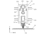
次に、Xステージ21について説明する。図2はXステージ21の構成を示す図である。なお、図1ではXステージ21の外側を覆うカバーを取り付けた状態を示しているが、図2ではカバーを外して内部機構が見えるようにして示してある。
Xステージ21には、リニアガイド25によって案内されるベースプレート31が設けてあり、ベースプレート31上にはローラ32をZ方向に移動させるためのZ軸駆動機構33が設けてある。
Z軸駆動機構33は、Zステージ34と、Zステージ34をZ方向に駆動させるボールねじ機構35と、Zステージ34のZ方向の運動を案内するリニアガイド36とからなる。
Next, the
The
The Z-
Zステージ34にはローラ32を基板Gに押し当てる際の加圧機構である荷重印加シリンダ37が取り付けてあり、荷重印加シリンダ37のロッド37aには振動アクチュエータ38を介してローラヘッド40が取り付けてある。荷重印加シリンダ37は具体的には、エアシリンダ、サーボモータ、ボイスコイルモータ等を用いることができる。
振動アクチュエータ38は超磁歪素子が内蔵されており、必要に応じて振動を与えるためのものであり、オプションとして取り付けられている。振動アクチュエータ38を作動させることにより、ブレイク荷重が振動することでより強いブレイクを行うことができるようになる。
A
The
荷重印加シリンダ37は、Z軸駆動機構33によりローラ32の高さを調整した後で、ローラ32が基板Gを押圧する荷重を調整できるようにしてある。
The
図3は、ローラ32を支持するとともに振動アクチュエータ38の振動をローラ32に伝達するローラヘッド40の断面図である。ローラヘッド40は、振動アクチュエータ38が固定される本体部41と、ローラ32を回転自在に保持するホルダ42と、振動アクチュエータ38からの振動をホルダ42に伝達するシャフト43と、シャフト43の運動を案内するガイド44とを有する。ガイド44とシャフト43との間には、ボール(不図示)が組み込まれ、シャフト43がガイド44に対し滑らかに運動できるようにしてある。振動アクチュエータ38のロッド38aは、連結部45でシャフト43とねじ結合される。シャフト43の下端は本体部41から突き出てホルダにねじ結合されている。
ホルダ42の下端は二股に分かれ、ローラ32の回転軸を支持することにより、ローラ32が回転自在に支持される。
FIG. 3 is a cross-sectional view of the
The lower end of the
図4はローラ32の正面図および側面図である。ローラ32は、円柱形状をなしており、支軸を通すための孔61が回転中心に形成してある。ローラ32の具体的寸法は外径2mm〜50mm、厚み0.5mm〜10mmの範囲で選択可能であり、材質としては、基板との接触面に傷がつきにくいようにするため、ポリアセタール、ポリウレタンゴム等のゴム硬度Hsが20°〜90°の材料を使用してある。
FIG. 4 is a front view and a side view of the
ブレイク装置10は、コンピュータシステム(不図示)で制御され、コンピュータシステムによりX軸駆動機構22、Y軸駆動機構13、Z軸駆動機構33、テーブル回転機構14を始め、装置各部の操作が行われる。
The
(ブレイク方法)
続いて、ブレイク装置10を用いたブレイク方法の一実施形態について図面を用いて説明する。一般に、基板をXY方向にブレイクする場合に、(1)最初にX方向とY方向とにスクライブラインを形成するクロススクライブを行い、その後に、X方向、Y方向にブレイクを行う加工手順と、(2)X方向にスクライブラインを形成し、続いて、X方向のブレイクを行い、基板を短冊状に分断した後、Y方向のスクライブを行い、最後にY方向のブレイクを行う加工手順のいずれかが採用される。ここでは、説明の便宜上、後者である(2)の加工手順におけるX方向のスクライブ工程およびブレイク工程について説明するが、その後のY方向の分断についても同様の手順で分断が行われる。また、(1)のクロスクスライブを行う場合についてもブレイク工程については同様の手順が採用される。
(Break method)
Next, an embodiment of a breaking method using the
図5は、分断しようとするパネル製品P1〜P6となる領域が形成されたガラス基板M(マザー基板)の加工前の平面図およびA−A’断面図である。なお、図示するに際し便宜上、隣接するパネル製品どうしの間の端材領域は実際よりも幅広に描いてある。
ガラス基板Mは、基板G1と基板G2とが貼り合わされた構造を有しており、各パネル領域P1〜P6には端子Tとなる領域が含まれている。
FIG. 5 is a plan view and AA ′ cross-sectional view of a glass substrate M (mother substrate) on which regions to be panel products P1 to P6 to be divided are formed. For convenience of illustration, the end material region between adjacent panel products is drawn wider than it actually is.
The glass substrate M has a structure in which the substrate G1 and the substrate G2 are bonded to each other, and each panel region P1 to P6 includes a region to be a terminal T.
図6は図5のガラス基板Mにスクライブラインを形成するときの状態を示す平面図およびB−B’断面図である。ガラス基板MからパネルP1〜P6を切り出すために、基板G1側については、各パネルの端辺となる位置にスクライブラインS1〜S6を形成する。
スクライブラインS1〜S6は、例えばカッターホイールを各パネルの端辺に沿って移動させることで形成することができる。続いて、基板G1と同様に基板G2についてもスクライブラインS7〜S12を形成する。このときスクライブラインS1とスクライブラインS7、スクライブラインS3とスクライブラインS9、スクライブラインS5とスクライブラインS11とは端子Tを露出させるため、端子Tの幅だけ位置がずれるように形成される。なお、スクライブラインS2とスクライブラインS8、スクライブラインS4とスクライブラインS10、スクライブラインS6とスクライブラインS12とは対向するように形成される。
FIGS. 6A and 6B are a plan view and a BB ′ sectional view showing a state when a scribe line is formed on the glass substrate M of FIG. In order to cut out the panels P1 to P6 from the glass substrate M, the scribe lines S1 to S6 are formed on the substrate G1 side at positions serving as the end sides of each panel.
The scribe lines S1 to S6 can be formed, for example, by moving the cutter wheel along the edge of each panel. Subsequently, scribe lines S7 to S12 are formed on the substrate G2 as well as the substrate G1. At this time, the scribe line S1 and the scribe line S7, the scribe line S3 and the scribe line S9, and the scribe line S5 and the scribe line S11 are formed so as to be displaced by the width of the terminal T in order to expose the terminal T. Note that the scribe line S2 and the scribe line S8, the scribe line S4 and the scribe line S10, and the scribe line S6 and the scribe line S12 are formed to face each other.
図7は図6でスクライブラインが形成されたガラス基板Mに対し、ブレイクローラ32(図1参照)を圧接させるときの状態を示す平面図およびC−C’断面図である。
スクライブラインS1〜S6が形成された基板G1に対し、順次ローラ32を圧接させる。まず、スクライブラインS1に対するブレイクを行う場合に、ローラ32を圧接させる位置は、スクライブラインS1を挟んでパネルP1側(図7におけるS1の右側)とは反対側の端材領域側(図7におけるS1の左側)とし、スクライブラインS1の近傍でスクライブラインS1から1mmの距離だけ離隔された位置B1に、ローラ32の端がくるようにする。なお、スクライブラインS1との距離は0.5mm〜2mm程度であればよい。そして、スクライブラインS1に平行にローラ32を圧接転動させる。これによりスクライブラインS1には折り曲げて分断しようとする力が加わるようにする。そして、スクライブラインS1とローラ32の端とは、距離が1mm程度(0.5mm〜2mm)離れているので、従来のようにスクライブラインS1上を圧接していたときよりも大きな曲げモーメントが加わるようになっている。それゆえ、小さな荷重で分断が可能になり、端面強度も向上するようになる。
FIG. 7 is a plan view and a CC ′ sectional view showing a state when the break roller 32 (see FIG. 1) is pressed against the glass substrate M on which the scribe line is formed in FIG.
The
続いて、スクライブラインS2に対するブレイクを行う場合のローラ32を圧接させる位置は、スクライブラインS2を挟んでパネルP1側(図7におけるS2の左側)とは反対側の端材領域側(図7におけるS2の右側)とし、スクライブラインS1の近傍でスクライブラインS1から1mmの距離だけ離隔された位置B2に、ローラ32の端がくるようにする。この場合もスクライブラインS2との距離は0.5mm〜2mm程度であればよい。
以下、同様に、スクライブラインS3〜S6についてもそれぞれ端材領域側でスクライブラインS3〜S6から1mm程度離隔された位置B3〜B6にローラ32の端がくるようにして圧接する。
これにより、基板G1はスクライブラインS1〜S6に沿って従来よりも低荷重で分断することができるようになる。
Subsequently, the position at which the
Similarly, the scribe lines S3 to S6 are also pressed in such a manner that the ends of the
As a result, the substrate G1 can be divided along the scribe lines S1 to S6 with a lower load than before.
続いて、基板G2のスクライブラインS7〜S12についても同様に、パネルと反対側で、それぞれスクライブラインから1mm程度離隔させた位置B7〜B12にローラ32を当てて低荷重で押圧する。これにより、基板G1,G2両側の端面が形成される。このようにすることで、ブレイクの際に加わるブレイク荷重を小さくできるので、端面にかかる負荷が抑えられる結果、端面強度が強くなる。
また、ローラ32の振動がスクライブラインから離隔した位置に加わり、パネル側から離れた位置になるので、振動の影響が抑えられる結果、端面強度が強くなる。
Subsequently, the scribe lines S7 to S12 of the substrate G2 are similarly pressed on the opposite side of the panel with the
Further, since the vibration of the
そして、X方向のブレイクを行った後、続いてY方向についても同様のスクライブとブレイクを行うことにより、各パネルP1〜P6に分断される。 Then, after performing the break in the X direction, the same scribe and break are performed in the Y direction, so that the panels P1 to P6 are divided.
上記実施形態では、基板G1とG2とを貼り合わせた基板について説明したが、単板構造についても同様に本発明を適用することができる。 In the above embodiment, the substrate in which the substrates G1 and G2 are bonded to each other has been described. However, the present invention can also be applied to a single plate structure.
本発明のブレイク方法は、ガラス等の脆性材料からなる基板を、スクライブラインに沿ってブレイクする際に利用することができる。 The breaking method of the present invention can be used when a substrate made of a brittle material such as glass is broken along a scribe line.
10 ブレイク装置
12 テーブル
13 Y軸駆動機構
14 テーブル回転機構
21 Xステージ
22 X軸駆動機構
32 ローラ
33 Z軸駆動機構
37 荷重印加シリンダ
38 振動アクチュエータ
40 ローラヘッド
43 シャフト
44 ガイド
S スクライブライン
G 基板
DESCRIPTION OF
Claims (4)
ブレイク工程の際に、テーブル上に載置された脆性材料基板に対し、前記スクライブライン近傍でスクライブラインから片側に離隔した位置に沿ってブレイクローラを転動させて圧接することにより荷重を印加することを特徴とする脆性材料基板のブレイク方法。 A brittle material substrate breaking method comprising a step of forming a scribe line on a brittle material substrate and a breaking step of breaking along the scribe line,
During the breaking process, a load is applied to the brittle material substrate placed on the table by rolling and breaking the breaking roller along a position separated from the scribe line on one side in the vicinity of the scribe line. A method for breaking a brittle material substrate.
Priority Applications (5)
| Application Number | Priority Date | Filing Date | Title |
|---|---|---|---|
| JP2010024311A JP5129826B2 (en) | 2010-02-05 | 2010-02-05 | Breaking method for brittle material substrate |
| TW100104036A TWI426059B (en) | 2010-02-05 | 2011-02-01 | Method for disassembling brittle material substrates |
| CN201180004547.3A CN102596523B (en) | 2010-02-05 | 2011-02-01 | Method for breaking brittle material substrate |
| KR1020127009799A KR101323678B1 (en) | 2010-02-05 | 2011-02-01 | Method for breaking brittle material substrate |
| PCT/JP2011/052012 WO2011096388A1 (en) | 2010-02-05 | 2011-02-01 | Method for breaking brittle material substrate |
Applications Claiming Priority (1)
| Application Number | Priority Date | Filing Date | Title |
|---|---|---|---|
| JP2010024311A JP5129826B2 (en) | 2010-02-05 | 2010-02-05 | Breaking method for brittle material substrate |
Publications (2)
| Publication Number | Publication Date |
|---|---|
| JP2011161674A JP2011161674A (en) | 2011-08-25 |
| JP5129826B2 true JP5129826B2 (en) | 2013-01-30 |
Family
ID=44355386
Family Applications (1)
| Application Number | Title | Priority Date | Filing Date |
|---|---|---|---|
| JP2010024311A Expired - Fee Related JP5129826B2 (en) | 2010-02-05 | 2010-02-05 | Breaking method for brittle material substrate |
Country Status (5)
| Country | Link |
|---|---|
| JP (1) | JP5129826B2 (en) |
| KR (1) | KR101323678B1 (en) |
| CN (1) | CN102596523B (en) |
| TW (1) | TWI426059B (en) |
| WO (1) | WO2011096388A1 (en) |
Families Citing this family (11)
| Publication number | Priority date | Publication date | Assignee | Title |
|---|---|---|---|---|
| CN103412432B (en) * | 2013-08-29 | 2016-07-06 | 深圳市华星光电技术有限公司 | Liquid crystal panel sliver apparatus and splinter method |
| JP2016043505A (en) * | 2014-08-20 | 2016-04-04 | 三星ダイヤモンド工業株式会社 | Dividing method and dividing device of brittle material substrate |
| JP6413496B2 (en) | 2014-08-29 | 2018-10-31 | 三星ダイヤモンド工業株式会社 | Manufacturing method of liquid crystal display panel |
| JP2016104683A (en) | 2014-11-19 | 2016-06-09 | 坂東機工株式会社 | Splitting method of glass sheet, and splitting device therefor |
| CN104926097A (en) * | 2015-07-08 | 2015-09-23 | 常州市金海基机械制造有限公司 | Numerical control glass cutting machine |
| TW202039193A (en) * | 2016-02-26 | 2020-11-01 | 日商三星鑽石工業股份有限公司 | Method of dividing brittle substrate |
| JP6601388B2 (en) * | 2016-12-28 | 2019-11-06 | 坂東機工株式会社 | Glass plate folding method |
| CN108162068A (en) * | 2018-01-29 | 2018-06-15 | 广东利元亨智能装备有限公司 | A kind of board separating device and scoreboard charging equipment |
| CN111112808A (en) * | 2018-10-30 | 2020-05-08 | 三星钻石工业股份有限公司 | Substrate dividing apparatus and substrate dividing method |
| JP2021154502A (en) * | 2020-03-25 | 2021-10-07 | 三星ダイヤモンド工業株式会社 | Breaking method of brittle material substrate and substrate processing device |
| JP2022003001A (en) * | 2020-06-23 | 2022-01-11 | 日本電気硝子株式会社 | Manufacturing method of glass sheet, and manufacturing apparatus therefor |
Family Cites Families (10)
| Publication number | Priority date | Publication date | Assignee | Title |
|---|---|---|---|---|
| JPH07138039A (en) * | 1993-11-12 | 1995-05-30 | Fuji Xerox Co Ltd | Scribing apparatus |
| JP3810127B2 (en) * | 1996-04-25 | 2006-08-16 | 京セラ株式会社 | Glass substrate cutting method |
| KR100789455B1 (en) * | 2002-02-20 | 2007-12-31 | 엘지.필립스 엘시디 주식회사 | Cutting method of liquid crystal display panel |
| JP4169565B2 (en) * | 2002-10-11 | 2008-10-22 | 三星ダイヤモンド工業株式会社 | Brittle material substrate break method, apparatus and processing apparatus therefor |
| WO2004073946A1 (en) * | 2003-02-21 | 2004-09-02 | Mitsuboshi Diamond Industrial Co., Ltd. | Substrate-processing table and device |
| KR101003610B1 (en) * | 2003-09-24 | 2010-12-23 | 엘지디스플레이 주식회사 | Apparatus for cutting liquid crystal display panel and method for cutting thereof |
| WO2006070825A1 (en) * | 2004-12-28 | 2006-07-06 | Mitsuboshi Diamond Industrial Co., Ltd. | Method for cutting brittle material substrate and substrate cutting system |
| JP4742649B2 (en) * | 2005-04-05 | 2011-08-10 | ソニー株式会社 | Substrate break device for bonded substrates and substrate break method |
| EP1886782A1 (en) * | 2005-05-30 | 2008-02-13 | Mitsuboshi Diamond Industrial Co., Ltd. | Device and method for cutting off substrate of fragile material |
| US20060280920A1 (en) * | 2005-06-10 | 2006-12-14 | Abbott John S Iii | Selective contact with a continuously moving ribbon of brittle material to dampen or reduce propagation or migration of vibrations along the ribbon |
-
2010
- 2010-02-05 JP JP2010024311A patent/JP5129826B2/en not_active Expired - Fee Related
-
2011
- 2011-02-01 CN CN201180004547.3A patent/CN102596523B/en not_active Expired - Fee Related
- 2011-02-01 TW TW100104036A patent/TWI426059B/en not_active IP Right Cessation
- 2011-02-01 WO PCT/JP2011/052012 patent/WO2011096388A1/en active Application Filing
- 2011-02-01 KR KR1020127009799A patent/KR101323678B1/en active IP Right Grant
Also Published As
| Publication number | Publication date |
|---|---|
| KR101323678B1 (en) | 2013-11-04 |
| KR20120087920A (en) | 2012-08-07 |
| JP2011161674A (en) | 2011-08-25 |
| WO2011096388A1 (en) | 2011-08-11 |
| TWI426059B (en) | 2014-02-11 |
| CN102596523B (en) | 2014-10-08 |
| TW201144243A (en) | 2011-12-16 |
| CN102596523A (en) | 2012-07-18 |
Similar Documents
| Publication | Publication Date | Title |
|---|---|---|
| JP5129826B2 (en) | Breaking method for brittle material substrate | |
| TWI434812B (en) | Breaking device and breaking method | |
| JP4718546B2 (en) | Brittle material substrate cutting apparatus and method | |
| JP6039363B2 (en) | Method and apparatus for dividing brittle material substrate | |
| TWI435852B (en) | Crossing Method and Segmentation Method of Fragile Material Substrate | |
| CN106458693B (en) | Method and apparatus for cutting multiple radii in flexible thin glass | |
| KR102259441B1 (en) | Breaking apparatus and dividing method | |
| JP2006199553A (en) | Apparatus and method for severing substrate | |
| KR101155027B1 (en) | Substrate dividing apparatus and method for dividing substrate using thereof | |
| JP5281544B2 (en) | Break device | |
| US20140144965A1 (en) | Method to manipulate brittle material sheet compound shape | |
| JP6450238B2 (en) | Peeling device | |
| JP5996376B2 (en) | Hard brittle plate cleaving device | |
| KR20150043240A (en) | Cutting method for tempered glass | |
| TWI661920B (en) | Breaking method and breaking device for composite substrate | |
| JP2016132227A (en) | Transfer device and transfer method | |
| JP6251061B2 (en) | Scribing device for brittle material substrate | |
| CN104511973B (en) | The breaking method thereof and brisement device of brittle substrate | |
| CN109553286B (en) | Scribing equipment | |
| US10301211B2 (en) | Mechanically forming crack initiation defects in thin glass substrates using an abrasive surface | |
| WO2017104386A1 (en) | Manufacturing method and manufacturing device for glass plate | |
| JP5276736B2 (en) | Break method | |
| JP2021154502A (en) | Breaking method of brittle material substrate and substrate processing device | |
| KR101123620B1 (en) | Breaking apparatus | |
| JP6445863B2 (en) | Method and apparatus for dividing plate material of brittle material |
Legal Events
| Date | Code | Title | Description |
|---|---|---|---|
| A131 | Notification of reasons for refusal |
Free format text: JAPANESE INTERMEDIATE CODE: A131 Effective date: 20120807 |
|
| A521 | Request for written amendment filed |
Free format text: JAPANESE INTERMEDIATE CODE: A523 Effective date: 20120913 |
|
| TRDD | Decision of grant or rejection written | ||
| A01 | Written decision to grant a patent or to grant a registration (utility model) |
Free format text: JAPANESE INTERMEDIATE CODE: A01 Effective date: 20121009 |
|
| A01 | Written decision to grant a patent or to grant a registration (utility model) |
Free format text: JAPANESE INTERMEDIATE CODE: A01 |
|
| A61 | First payment of annual fees (during grant procedure) |
Free format text: JAPANESE INTERMEDIATE CODE: A61 Effective date: 20121102 |
|
| R150 | Certificate of patent or registration of utility model |
Ref document number: 5129826 Country of ref document: JP Free format text: JAPANESE INTERMEDIATE CODE: R150 Free format text: JAPANESE INTERMEDIATE CODE: R150 |
|
| FPAY | Renewal fee payment (event date is renewal date of database) |
Free format text: PAYMENT UNTIL: 20151109 Year of fee payment: 3 |
|
| LAPS | Cancellation because of no payment of annual fees |