JP5120850B2 - Method, apparatus and computer program for filtering snoop requests using stream registers - Google Patents
Method, apparatus and computer program for filtering snoop requests using stream registers Download PDFInfo
- Publication number
- JP5120850B2 JP5120850B2 JP2008504137A JP2008504137A JP5120850B2 JP 5120850 B2 JP5120850 B2 JP 5120850B2 JP 2008504137 A JP2008504137 A JP 2008504137A JP 2008504137 A JP2008504137 A JP 2008504137A JP 5120850 B2 JP5120850 B2 JP 5120850B2
- Authority
- JP
- Japan
- Prior art keywords
- snoop
- cache
- address
- register
- filter
- Prior art date
- Legal status (The legal status is an assumption and is not a legal conclusion. Google has not performed a legal analysis and makes no representation as to the accuracy of the status listed.)
- Expired - Fee Related
Links
Images


Classifications
-
- G—PHYSICS
- G06—COMPUTING; CALCULATING OR COUNTING
- G06F—ELECTRIC DIGITAL DATA PROCESSING
- G06F12/00—Accessing, addressing or allocating within memory systems or architectures
- G06F12/02—Addressing or allocation; Relocation
- G06F12/08—Addressing or allocation; Relocation in hierarchically structured memory systems, e.g. virtual memory systems
- G06F12/0802—Addressing of a memory level in which the access to the desired data or data block requires associative addressing means, e.g. caches
- G06F12/0806—Multiuser, multiprocessor or multiprocessing cache systems
- G06F12/0815—Cache consistency protocols
- G06F12/0831—Cache consistency protocols using a bus scheme, e.g. with bus monitoring or watching means
-
- G—PHYSICS
- G06—COMPUTING; CALCULATING OR COUNTING
- G06F—ELECTRIC DIGITAL DATA PROCESSING
- G06F12/00—Accessing, addressing or allocating within memory systems or architectures
- G06F12/02—Addressing or allocation; Relocation
- G06F12/08—Addressing or allocation; Relocation in hierarchically structured memory systems, e.g. virtual memory systems
- G06F12/0802—Addressing of a memory level in which the access to the desired data or data block requires associative addressing means, e.g. caches
- G06F12/0806—Multiuser, multiprocessor or multiprocessing cache systems
- G06F12/0815—Cache consistency protocols
- G06F12/0817—Cache consistency protocols using directory methods
- G06F12/0822—Copy directories
-
- G—PHYSICS
- G06—COMPUTING; CALCULATING OR COUNTING
- G06F—ELECTRIC DIGITAL DATA PROCESSING
- G06F13/00—Interconnection of, or transfer of information or other signals between, memories, input/output devices or central processing units
- G06F13/14—Handling requests for interconnection or transfer
- G06F13/20—Handling requests for interconnection or transfer for access to input/output bus
- G06F13/28—Handling requests for interconnection or transfer for access to input/output bus using burst mode transfer, e.g. direct memory access DMA, cycle steal
-
- G—PHYSICS
- G06—COMPUTING; CALCULATING OR COUNTING
- G06F—ELECTRIC DIGITAL DATA PROCESSING
- G06F2212/00—Indexing scheme relating to accessing, addressing or allocation within memory systems or architectures
- G06F2212/50—Control mechanisms for virtual memory, cache or TLB
- G06F2212/507—Control mechanisms for virtual memory, cache or TLB using speculative control
-
- Y—GENERAL TAGGING OF NEW TECHNOLOGICAL DEVELOPMENTS; GENERAL TAGGING OF CROSS-SECTIONAL TECHNOLOGIES SPANNING OVER SEVERAL SECTIONS OF THE IPC; TECHNICAL SUBJECTS COVERED BY FORMER USPC CROSS-REFERENCE ART COLLECTIONS [XRACs] AND DIGESTS
- Y02—TECHNOLOGIES OR APPLICATIONS FOR MITIGATION OR ADAPTATION AGAINST CLIMATE CHANGE
- Y02D—CLIMATE CHANGE MITIGATION TECHNOLOGIES IN INFORMATION AND COMMUNICATION TECHNOLOGIES [ICT], I.E. INFORMATION AND COMMUNICATION TECHNOLOGIES AIMING AT THE REDUCTION OF THEIR OWN ENERGY USE
- Y02D10/00—Energy efficient computing, e.g. low power processors, power management or thermal management
Description
本発明は、一般的に多重プロセッサ・アーキテクチャを有するコンピュータ・システムに関し、さらに具体的には、かかる多重プロセッサ・システムにおけるメモリ・アクセス要求を処理しキャッシュ・コヒーレンスを実現するための、新しい多重プロセッサ・コンピュータ・システムに関する。 The present invention relates generally to computer systems having a multiprocessor architecture, and more particularly to a new multiprocessor system for processing memory access requests and implementing cache coherence in such multiprocessor systems. It relates to a computer system.
高いパフォーマンスのコンピューティングを実現するために、複数の個別プロセッサが相互連結され、並行処理が可能な多重プロセッサ・コンピュータ・システムが形成されている。複数のプロセッサを単一のチップ又は数個のチップに配置し、各チップに一つ又は数個のプロセッサを包含させ、多重プロセッサ・コンピュータ・システムとして相互連結させることができる。 In order to achieve high performance computing, a plurality of individual processors are interconnected to form a multiprocessor computer system capable of parallel processing. Multiple processors may be located on a single chip or several chips, each chip containing one or several processors and interconnected as a multiprocessor computer system.
多重プロセッサ・コンピュータ・システム中のプロセッサは、自己専用のキャッシュ・メモリを使用し、アクセス・タイムの短縮(キャッシュは、プロセッサに対しローカルで、データへの高速なアクセスが得られる)と主メモリに対するメモリ請求の回数低減とを図っている。しかしながら、多重プロセッサ・システムのキャッシュの管理は複雑である。複数の専用キャッシュは、主メモリのデータの複数のコピーが多重プロセッサ・システム中に同時に存在し得ることに起因する、多重キャッシュのコヒーレンシ問題(又はデータ陳腐化問題)を引き起こす。 Processors in multiprocessor computer systems use their own dedicated cache memory to reduce access time (cache is local to the processor and provides fast access to data) and main memory The number of memory requests is reduced. However, managing a multiprocessor system's cache is complex. Multiple dedicated caches cause multiple cache coherency problems (or data staleness problems) due to the fact that multiple copies of main memory data may exist simultaneously in a multiprocessor system.
小規模の共用メモリ多重処理システムは、単一のバスで相互連結された複数プロセッサ(又はその群)を有する。しかし、プロセスの速度が向上するにつれ、バスを効果的に共用できるプロセッサの実施可能数が減少する。 A small shared memory multiprocessing system has multiple processors (or groups) interconnected by a single bus. However, as the speed of the process increases, the feasible number of processors that can effectively share the bus decreases.
複数プロセッサ間のコヒーレンスを維持するプロトコルは、キャッシュ・コヒーレンス・プロトコルと呼ばれる。キャッシュ・コヒーレンス・プロトコルは、プロセッサ間の一切のデータ・ブロックの共用を追跡する。どのようにデータ共用を追跡するかによって、キャッシュ・コヒーレンス・プロトコルを2つのクラスに分類することができる。すなわち、1)ディレクトリ・ベースと、2)スヌーピングである。 A protocol that maintains coherence between multiple processors is called a cache coherence protocol. The cache coherence protocol tracks the sharing of any data block between processors. Depending on how data sharing is tracked, cache coherence protocols can be classified into two classes. 1) directory based and 2) snooping.
ディレクトリ・ベースのアプローチでは、物理メモリのブロックの共用状態は、コヒーレンシ・ディレクトリと呼ばれるただ一つのロケーションに置かれる。コヒーレンシ・ディレクトリは、一般に、多重プロセッサ・コンピュータ・システム中のどのプロセッサが、どのメモリのラインを有しているかを追跡記録する大きなメモリ・ブロックである。不都合なことに、コヒーレンシ・ディレクトリは、通常、大きくて遅い。これらは、全体的システム・パフォーマンスを大きく低下させる。というのは、これらのディレクトリでは、メモリへの各アクセスが共用ディレクトリを通過することが必要なので、あらゆるメモリ・アクセス要求に対し余分な待ち時間をもたらすからである。 In a directory-based approach, the shared state of a block of physical memory is placed in a single location called a coherency directory. A coherency directory is typically a large block of memory that keeps track of which processor in a multiprocessor computer system has which line of memory. Unfortunately, coherency directories are usually large and slow. These greatly reduce overall system performance. This is because these directories introduce extra latency for every memory access request because each access to memory must pass through the shared directory.
図1は、キャッシュ・コヒーレンシに対しコヒーレンシ・ディレクトリによるアプローチを用いた、典型的な従来技術の多重プロセッサ・システム10を示す。多重プロセッサ・システム10は、共用バス24を介し、それぞれメモリ・コントローラ22a、22bを通して主メモリ20a、20bに相互接続されたいくつかのプロセッサ15a、…、15dを含む。各プロセッサ15a、…、15dは、それぞれ自分専用のキャッシュ17a、…、17dを有し、Nウェイ・セット・アソシアティブである。プロセッサからのメモリに対する各要求は、プロセッサ・バス24上に置かれ、コヒーレンシ・コントローラ26に向けられる。多くの場合、コヒーレンシ・コントローラ中には、特定のサブシステム中に保持されているキャッシュ・ラインのロケーションを追跡するモジュールが包含されており、キャッシング・エージェントすべてに不必要なスヌープ要求を一せい同報する必要性をなくす。このユニットはしばしば「スヌープ・コントローラ」又は「スヌープ・フィルタ」と呼ばれる。また、I/Oシステム28からの全メモリ・アクセス要求もコヒーレンシ・コントローラ26に向けられる。主メモリの代わりに、主メモリに接続された二次的なキャッシュを使うことができる。プロセッサを、プロセッサ・クラスタにグループ化し、各クラスタに自己のクラスタ・バスを持たせ、これをコヒーレンシ・コントローラ26に連結することができる。各メモリ要求がコヒーレンシ・ディレクトリを通過する際に、各要求に対し、要求されるメモリ・ブロックの状態をチェックするための追加サイクルが加えられる。
FIG. 1 illustrates a typical prior
スヌーピング・アプローチにおいては、集中体制は取られず、代わりに各キャッシュが、データ・ブロックの共用状態をローカルに保存する。キャッシュは、通常、共用メモリ・バスにつながっており、すべてのキャッシュ・コントローラはバスを探り(モニタし)、コントローラが、要求するデータ・ブロックのコピーを持っているかどうかを判断する。一般に用いられるスヌーピング方法は、「write−invalidate」プロトコルである。このプロトコルでは、プロセッサは、データに書き込みをする前に、当該データに対して自分だけがアクセスすることを確実にする。書き込みをする毎に、他のすべてのキャッシュ中の当該データの他のコピー全部が無効にされる。2つ以上のプロセッサが同時に同一のデータに書き込みをしようとすると、その一つだけが勝ち残り他のプロセッサのコピーは無効にされる。 In the snooping approach, no centralized system is taken, instead each cache stores the shared state of the data block locally. The cache is usually connected to a shared memory bus, and all cache controllers probe (monitor) the bus to determine if the controller has a copy of the requested data block. A commonly used snooping method is the “write-invalidate” protocol. In this protocol, the processor ensures that only the user has access to the data before writing it. Every time you write, all other copies of the data in all other caches are invalidated. If two or more processors attempt to write to the same data at the same time, only one of them will win and the other processor's copy will be invalidated.
write−invalidateプロトコル・ベースのシステムにおいて書き込みを行うため、プロセッサは共用バスを必要とし、バスを介して無効にされるアドレスを一せい同報する。すべてのプロセッサは、バスをスヌープして、当該データが自分のキャッシュ中にあるかどうかをチェックする。ある場合、それらデータは無効にされる。かくして、共用バスを使って書き込みの逐次化が行われる。 In order to write in a write-invalidate protocol based system, the processor requires a shared bus and broadcasts all invalidated addresses over the bus. All processors snoop on the bus to check if the data is in their cache. If there are, they are invalidated. Thus, write serialization is performed using the shared bus.
不都合なこととして、スヌーピング・アプローチにおけるあらゆるバス・トランザクションでは、キャッシュ・アドレス・タグを確認しなければならず、これがCPUのキャッシュ・アクセスを妨げる可能性がある。最新式のアーキテクチャでは、通常、アドレス・タグを複製し、CPUの要求とスヌーピング要求とが並行して進められるようにして、これを低減している。別のアプローチでは、内包型の多層レベル・キャッシュを用い、一次キャッシュへのあらゆる入力を低レベルのキャッシュ中に複製する。こうして、スヌープ作業を二次レベルのキャッシュで行い、CPUの作業を妨げないようにする。 Unfortunately, every bus transaction in the snooping approach must check the cache address tag, which can prevent CPU cache access. Modern architectures typically reduce address tags by duplicating them so that CPU requests and snooping requests can proceed in parallel. Another approach uses an inclusive multi-level cache and replicates any input to the primary cache into a low level cache. Thus, the snoop work is performed in the secondary level cache so that the CPU work is not hindered.
図2は、キャッシュ・コヒーレンシのためスヌーピング・アプローチを使った典型的な従来技術の多重プロセッサ・システム50を示す。多重プロセッサ・システム50は、共用バス56を介して主メモリ58に相互接続されたいくつかのプロセッサ52a、…、52cを含む。各プロセッサ52a、…、52cは、それぞれ自分専用のキャッシュ54a、…、54cを有し、Nウェイ・セット・アソシアティブである。プロセッサからのメモリに対する各書き込み要求は、プロセッサ・バス56上に置かれる。すべてのプロセッサは、バスをスヌープし、自分のキャッシュをチェックして書き込み対象アドレスが自分のキャッシュ中に所在しているかどうかを見る。所在する場合、当該アドレスに対応するデータは無効にされる。いくつかの多重プロセッサ・システムでは、各プロセッサに対しローカルにモジュールを付加し、無効にされるキャッシュ・ラインが特定のキャッシュ中に保持されているかどうかを追跡させ、ローカルでのスヌーピング作業を効果的に削減している。このユニットは、しばしば「スヌープ・フィルタ」と呼ばれる。主メモリの代わりに、主メモリに連結された二次キャッシュを使うことができる。
FIG. 2 shows a typical prior
バスにつながるプロセッサ数が増えるにつれ、同様にスヌーピング作業も増加する。キャッシュに対する不必要なスヌープ要求は、プロセッサのパフォーマンスを低下させ、各スヌープ要求のキャッシュ・ディレクトリへのアクセスによりパワーが消費される。さらに、スヌーピング作業を支援するため、あらゆるプロセッサに対しキャッシュ・ディレクトリを複製することは、チップのサイズを大幅に増大させる。このことは、単一チップ上に設けられたパワー量の限定されたシステムに対しては特に重要である。 As the number of processors connected to the bus increases, so too does the snooping work. Unnecessary snoop requests to the cache degrade processor performance and power is consumed by accessing each snoop request's cache directory. In addition, replicating the cache directory for every processor to support the snooping task greatly increases the size of the chip. This is particularly important for systems with limited power provided on a single chip.
以下は、多重プロセッサ・システムで判明した、従来のスヌーピング・アプローチのさまざまな問題に取り組んだ従来技術の参考文献の内容である。 The following is the contents of a prior art reference addressing various problems of the conventional snooping approach found in multiprocessor systems.
具体的には、米国特許出願公開第2003/0135696(A1)号、及び米国特許第6,704、845(B2)号の双方は、スヌープ・フィルタを含むコヒーレンス・ディレクトリ・ベースのアプローチのための、スヌープ・フィルタのエントリを置換える置換え基準を記載している。このスヌープ・フィルタは、キャッシュ格納されたメモリ・ブロックに関する情報を包含しており、キャッシュ・ラインとその状態がキャッシュ格納されている。米国特許出願公開第2004/0003184(A1)号は、遠隔ノードにアクセスされるローカル・キャッシュ・ラインを記録する偶数番及び奇数番のアドレス・ラインを記録するためのサブスヌープ・フィルタを包含するスヌープ・フィルタを記載している(サブフィルタは、同じフィルタリング・アプローチを使う)。これらの開示のいずれも、多重プロセッサ・システムにおいて、各キャッシュに送られるスヌープ要求の数をローカル的に低減するためのシステム及び方法については教示も提案もしていない。また、これらは、各種のフィルタリング方法を使っていくつかのスヌープ・フィルタを結合することについても、教示も提案もしておらず、さらに、スヌーピング情報の2点間相互接続をキャッシュに具えることも教示も提案もしていない。 Specifically, both U.S. Patent Application Publication No. 2003/0135696 (A1) and U.S. Pat. No. 6,704,845 (B2) are for coherence directory based approaches that include snoop filters. Describes replacement criteria for replacing snoop filter entries. The snoop filter contains information about cached memory blocks, and cache lines and their states are cached. US 2004/0003184 (A1) discloses a snoop that includes a sub-snoop filter for recording even and odd address lines that record local cache lines accessed by remote nodes. Lists filters (subfilters use the same filtering approach). None of these disclosures teach or suggest a system and method for locally reducing the number of snoop requests sent to each cache in a multiprocessor system. They also do not teach or suggest combining several snoop filters using various filtering methods, and may also include a point-to-point interconnection of snooping information in the cache. Neither teaching nor proposing.
米国特許出願公開第2003/0070016(A1)号及び米国特許出願公開第2003/0005843(A1)号は、スヌープ・フィルタを包含する中央コヒーレンシ・ディレクトリを備えた多重プロセッサ・システムについて記載している。これらの出願に記載されたスヌープ・フィルタはスヌープ要求を処理するサイクル数を減少させるが、キャッシュに送られるスヌープ要求の数は低減しない。 U.S. Patent Application Publication No. 2003/0070016 (A1) and U.S. Patent Application Publication No. 2003/0005843 (A1) describe multiprocessor systems with a central coherency directory that includes a snoop filter. The snoop filters described in these applications reduce the number of cycles to process a snoop request, but do not reduce the number of snoop requests sent to the cache.
米国特許第5,966,729号は、キャッシュ・コヒーレンスのためのスヌーピング・アプローチと各プロセッサ群にローカル的に関連付けられたスヌープ・フィルタとを使う、共用バスの多重プロセッサ・システムを記載している。スヌーピング作業を削減するため、特定キャッシュ・ラインに「関与のある」遠隔プロセッサ群と「関与のない」群とのリストが保持される。スヌープ要求は「関与のある」とマークされたプロセッサ群にだけ送られ、これにより一せい同報されるスヌープ要求の数は削減される。該出願は、ローカルのプロセッサに対するスヌープ要求の数をいかに削減するかでなく、むしろ、「関与のない」とマークされた他のプロセッサ群に送られるスヌープ要求の数をいかに低減するかを記載している。この対処策は、プロセッサ群に対するキャッシュ中の各ライン毎にこれに関与するプロセッサ群の情報を含むリストを保持することが必要となり、これは、サイズにおいて当該プロセッサ群中の各プロセッサのキャッシュ・ディレクトリを複製するのに匹敵し、従ってチップのサイズを大幅に拡大する。 US Pat. No. 5,966,729 describes a shared bus multiprocessor system that uses a snooping approach for cache coherence and a snoop filter locally associated with each processor group. . To reduce snooping work, a list of remote processors that are “involved” and “not involved” in a particular cache line is maintained. Snoop requests are sent only to processors that are marked “involved”, which reduces the number of snoop requests that are broadcast at all. The application does not describe how to reduce the number of snoop requests to the local processor, but rather how to reduce the number of snoop requests sent to other processors that are marked "not involved". ing. This workaround requires that for each line in the cache for a processor group, a list containing information about the processor group involved in this is maintained, which in size is the cache directory for each processor in that processor group. And thus greatly increase the size of the chip.
米国特許第6,389,517(B1)号は、2つのアクセス・キューを具え、プロセッサ及びスヌープ・アクセスの両方からのキャッシュへの同時アクセスを可能にする、キャッシュ・コヒーレンスをスヌーピングする方法を記載している。開示された実施形態は共用バス構成を対象としている。該特許は、キャッシュに渡されるスヌープ要求の数を減少させる方法については記載していない。 US Pat. No. 6,389,517 (B1) describes a method of snooping cache coherence that includes two access queues and allows simultaneous access to the cache from both processor and snoop access. doing. The disclosed embodiments are directed to a shared bus configuration. The patent does not describe how to reduce the number of snoop requests passed to the cache.
米国特許第5,572,701号は、低速のバスの高速バス及びプロセッサへの妨害を低減するために、バス・ベースのスヌープ方法を記載している。スヌープ・バス制御ユニットは、プロセッサが高速バスへのリリースを完了するまで、低速のバスからのアドレス及びデータを一時格納する。該ユニットは、その後にデータを転送し、キャッシュ中の対応するラインを無効にする。この開示は、全構成要素が高速バスを介して交信する多重プロセッサ・システムについては記載していない。 U.S. Pat. No. 5,572,701 describes a bus-based snoop method to reduce the interference of a low speed bus to a high speed bus and processor. The snoop bus control unit temporarily stores addresses and data from the low speed bus until the processor completes the release to the high speed bus. The unit then transfers the data and invalidates the corresponding line in the cache. This disclosure does not describe a multiprocessor system in which all components communicate via a high speed bus.
A.Moshovos(モシュボス)、G.Memik(メミク)、B.Falsafi(フォルサフィ)及びA.Choudhary(チョードリ)は、「JETTY:filtering snoops for reduced energy consumption in SMP servers(JETTY:SMPサーバにおける低エネルギー消費のためのフィルタリング・スヌープ)」(「Jetty」)という題名の文献の中で、ハードウエア・フィルタを用いてスヌープ要求を削減するためのいくつかの提案を記載している。該文献は、スヌープ要求が共用システム・バスを介して配送される多重プロセッサ・システムを記載している。プロセッサに送られるスヌープ要求の数を削減するため、一つ又は数個のさまざまなフィルタが用いられる。 A. Moshovos (Moshbos), G.M. Memik, B.M. Falsafi and A.I. Caudary is in the title of “JETTY: Filtering Snoops for Low Energy Consumption in SMP Servers” (“JETTY”). Describes several suggestions for using filters to reduce snoop requirements. The document describes a multiprocessor system in which snoop requests are delivered over a shared system bus. One or several different filters are used to reduce the number of snoop requests sent to the processor.
しかしながら、Jettyに記載されたシステムは、パフォーマンス、支援システム、さらに具体的には相互接続アーキテクチャに関し重大な限界があり、マルチポート化への対応が欠けている。さらに具体的には、Jettyに記載されたアプローチは、システム全体に亘って共通イベント順序付けを設定した共用システム・バスに基づいている。このようなグローバルな時間順序付けは、フィルタ・アーキテクチャを単純化する上では望ましいが、単一共用バスを使うシステムに対しては可能なシステム構成を制限してしまう。残念なことに、共用バス・システムは、単一のグローバル資源に対する競合に起因して、拡張性に限界があることが知られている。さらに、グローバルなバスは、これらに付属する複数の構成要素の大きな負荷に起因して低速になりがちで、チップ型多重プロセッサ中に配置するのは非効率的である。 However, the system described in Jetty has significant limitations with regard to performance, support systems, and more specifically interconnect architectures, and lacks support for multiporting. More specifically, the approach described in Jetty is based on a shared system bus that sets a common event ordering throughout the system. Such global time ordering is desirable to simplify the filter architecture, but limits the possible system configurations for systems using a single shared bus. Unfortunately, shared bus systems are known to have limited scalability due to contention for a single global resource. In addition, global buses tend to be slow due to the heavy load of the components attached to them, and are inefficient to place in chip-type multiprocessors.
従って、高度に最適化された高帯域システムにおいては、スター型、又は2点間実装のような別のシステム・アーキテクチャを具えるのが望ましい。これらには利点がある、というのは、これらは、単一組の送信者と伝送者とを有し、負荷を低減し、高速プロトコルの使用を可能にし、チップ多重プロセッサのレイアウトを単純化するからである。また、2点間プロトコルを使うことによって、いくつもの送信を同時に進行させることができ、これにより、データ伝送の並行処理及び全体的データ・スループットが増大する。 Thus, in a highly optimized high bandwidth system, it is desirable to have another system architecture such as a star or point-to-point implementation. They have advantages because they have a single set of senders and transmitters, reduce the load, enable the use of high-speed protocols, and simplify the layout of chip multiprocessors. Because. Also, by using a point-to-point protocol, a number of transmissions can proceed simultaneously, which increases parallel processing of data transmission and overall data throughput.
Jettyの他の限界には、いくつもの要求に対するスヌープ・フィルタリングを同時に実施できないことが含まれ、Jettyにあるように、いくつものプロセッサからの同時のスヌープ要求は、システム・バスがそれらを逐次化しなければならない。いくつものスヌープ要求の同時処理を可能にすることによって、一度に取り扱える要求の数の大幅な増加が得られ、これにより全体的システム・パフォーマンスが向上されよう。 Other limitations of Jetty include the inability to perform snooping filtering on a number of requests simultaneously, and as in Jetty, simultaneous snoop requests from a number of processors must be serialized by the system bus. I must. By allowing simultaneous processing of several snoop requests, a significant increase in the number of requests that can be handled at one time will be obtained, which will improve overall system performance.
従来技術の限界を示してきたが、必要とされるものは、システム設計の選択肢を制限することなく、スヌープ・フィルタを組み込み、全体的パフォーマンス及びパワー効率を増進させるシステム、さらに具体的には、共通バスを必要としないシステムにおいてスヌープ・フィルタリングをサポートする方法及び装置であることは明らかである。 Although the limitations of the prior art have been shown, what is needed is a system that incorporates a snoop filter, without limiting system design options, to improve overall performance and power efficiency, and more specifically, It is clear that the method and apparatus supports snoop filtering in systems that do not require a common bus.
さらに、2点間接続を用いるシステムをサポートし、スヌープ・フィルタリングを用いた高パフォーマンスのシステム実行を可能にする、スヌープ・フィルタ・アーキテクチャが必要である。 In addition, there is a need for a snoop filter architecture that supports systems using point-to-point connections and enables high performance system execution using snoop filtering.
複数のスヌープ・フィルタ・ユニットを同時に動作させて、複数メモリ書き込み元からの要求を同時にフィルタし、システム・パフォーマンスを向上させることがさらに求められる。 There is a further need to operate multiple snoop filter units simultaneously to simultaneously filter requests from multiple memory writers and improve system performance.
パイプライン方式で実行できる新規の高パフォーマンス・スヌープ・フィルタを実現し、このようなスヌープ・フィルタを利用するシステムにおいて高いシステム・クロック速度を可能にすることがさらに求められる。 There is a further need to implement a new high performance snoop filter that can be implemented in a pipelined manner and to enable high system clock speeds in systems that utilize such snoop filters.
従来技術の限界を乗り越えた高いフィルタリング効率持つスヌープ・フィルタがさらに求められる。 There is a further need for a snoop filter with high filtering efficiency that overcomes the limitations of the prior art.
従って、本発明の目的は、キャッシュ・コヒーレント多重プロセッサ・システムにおいて、一つのプロセッサに送られるスヌープ要求の数を減らすための簡単な方法及び装置を提供することである。 Accordingly, it is an object of the present invention to provide a simple method and apparatus for reducing the number of snoop requests sent to a single processor in a cache coherent multiprocessor system.
本発明のさらなる目的は、入来するスヌープ要求をフィルタする簡単なハードウエア・デバイスを、各プロセッサにローカル的に加えることによって、ローカルでのスヌーピング作業を効果的に削減する方法及び装置を提供することである。前述のスヌープ・フィルタは、プロセッシング・ユニットに関連付けられたローカル・キャッシュ・メモリ中にロードされたデータを追跡するためにストリーム・レジスタを活用し、キャッシュ・ミスとなる可能性の高いスヌープ要求を識別し、そのほとんどをフィルタ除去するが、ローカルにキャッシュ格納する対象としてストリーム・レジスタに示されているデータに対するスヌープ要求を除去することはしない。プロセッサあたりのスヌープ要求の数を低減することによってシステム・パフォーマンスが向上されパワーが節減される。 It is a further object of the present invention to provide a method and apparatus that effectively reduces local snooping work by adding a simple hardware device that filters incoming snoop requests locally to each processor. That is. The aforementioned snoop filter utilizes stream registers to track data loaded into the local cache memory associated with the processing unit and identifies snoop requests that are likely to result in cache misses However, most of them are filtered out, but they do not remove snoop requests for data that is indicated in the stream register for cache locally. Reducing the number of snoop requests per processor improves system performance and saves power.
本発明の第一の態様によれば、複数のプロセッシング・ユニットを備えたコンピューティング環境中の単一のプロセッシング・ユニットに関連付けられたスヌープ・フィルタ装置が提供され、各プロセッシング・ユニットはそれに関連付けられた一つ以上のキャッシュ・メモリを有し、該スヌープ・フィルタは、
関連するプロセッサのキャッシュ・メモリ・レベル中にロードされているデータのキャッシュ・ライン・アドレスを追跡するようになされた第一メモリ格納手段と、
一つ以上のメモリ書き込み元からのスヌープ要求を受信するための手段と、
受信したスヌープ要求のアドレスを前記メモリ格納手段に格納されているアドレスと対比する手段と、
メモリ格納手段中のアドレスとの一致を受けて受信したスヌープ要求を転送するか、さもなくば、スヌープ要求を廃棄するための手段と、
を含み、
これらによりプロセッシング・ユニットに転送されるスヌープ要求の数が大幅に削減され、それによって、コンピューティング環境のパフォーマンスが増進される。
According to a first aspect of the present invention, there is provided a snoop filter device associated with a single processing unit in a computing environment comprising a plurality of processing units, each processing unit being associated therewith. have one or more cache memory has, the snoop filter,
First memory storage means adapted to track the cache line address of the data being loaded during the cache memory level of the associated processor;
Means for receiving a snoop request from one or more memory writers;
Means for comparing the address of the received snoop request with the address stored in the memory storage means;
A means for forwarding a received snoop request in response to a match with an address in the memory storage means, or a means for discarding the snoop request;
Including
These greatly reduce the number of snoop requests that are forwarded to the processing unit, thereby enhancing the performance of the computing environment.
さらに具体的には、スヌープ・フィルタは各プロセッシング・ユニットに関連付けられており、ストリーム・レジスタ・セットと関連するストリーム・レジスタ対比ロジックとの使用に基づいてフィルタリング方法を実行する少なくとも一つのスヌープ・フィルタ基本要素を含む。どの時点においても、複数のストリーム・レジスタ・セットの中の少なくとも一つのストリーム・レジスタ・セットはアクチブであり、少なくとも一つのストリーム・レジスタ・セットは履歴と標識される。さらに、スヌープ・フィルタ・ブロックは、キャッシュ・ラップ検知ロジックと動作可能に結合され、これにより、キャッシュ・ラップ状態が検知されると、アクチブなストリーム・レジスタ・セットの内容は履歴ストリーム・レジスタ・セットに移し替えられ、少なくとも一つのアクチブなストリーム・レジスタ・セットの内容がリセットされる。各フィルタ基本要素は、ストリーム・レジスタ対比ロジックを実行し、受信したスヌープ要求をプロセッサに転送するかあるいは廃棄するかを判断する。受信されたスヌープ要求は、ストリーム・レジスタと対比され、判定が行われ、キャッシュ中にエントリがあり得るかどうかが示されるが、その実際のレジデンス状態は示されない。 More specifically, a snoop filter is associated with each processing unit and at least one snoop filter that performs a filtering method based on the use of a stream register set and associated stream register contrast logic. Contains basic elements. At any point in time, at least one stream register set of the plurality of stream register sets is active, and at least one stream register set is labeled as history. In addition, the snoop filter block is operably coupled with the cache wrap detection logic so that when a cache wrap condition is detected, the contents of the active stream register set is the history stream register set. And the contents of at least one active stream register set are reset. Each filter base element executes stream register contrast logic to determine whether the received snoop request is forwarded to the processor or discarded. The received snoop request is compared with the stream register and a determination is made indicating whether there may be an entry in the cache, but not its actual residence state.
さらに、ストリーム・レジスタ・セットに基づくフィルタ基本要素は、複数の、ベース・レジスタとマスク・レジスタとの対セットを含む。前述のスヌープ・フィルタ・ユニットが関連付けられたキャッシュ階層中にロードされる各新規データに対し、メモリ要求のアドレスは、きっちりと一つのベース・レジスタに書き込まれ、対となるマスク・レジスタは更新される。本発明によれば、選定されたストリーム・レジスタのマスク・レジスタは更新されて、値弁別性を減ずることによって、前に記録されていたアドレスとの差異を追跡記録する。 Further, the filter base element based on the stream register set includes a plurality of base register and mask register pair sets. For each new data loaded into the cache hierarchy with which the aforementioned snoop filter unit is associated, the address of the memory request is written exactly into one base register and the paired mask register is updated. The In accordance with the present invention, the mask register of the selected stream register is updated to track the difference from the previously recorded address by reducing value discrimination.
本発明の第二の態様によれば、複数のプロセッシング・ユニットを有するコンピューティング環境においてキャッシュ・コヒーレンシをサポートするためのスヌープ・フィルタリング方法が提供され、各プロセッシング・ユニットは、それに関連付けられた一つ以上のキャッシュ・メモリ、及び関連するスヌープ・フィルタ・デバイスを有し、該方法は、
プロセッシング・ユニット中の各スヌープ・フィルタ・デバイスについて、
関連するプロセッサのキャッシュ・メモリ・レベル中にロードされているデータのキャッシュ・ライン・アドレスを追跡記録し、キャッシュ・ライン・アドレスを第一メモリ格納手段に保存するステップと、
複数のメモリ書き込み元からスヌープ要求を受信するステップと、
受信したスヌープ要求のアドレスをメモリ格納手段中に格納されたアドレスと対比するステップと、
メモリ格納手段中のアドレスとの一致を受けて、受信したスヌープ要求をプロセッサに転送するか、さもなくば、スヌープ要求を廃棄するステップと、
を含み、
これにより、プロセッシング・ユニットに転送されるスヌープ要求の数が大幅に削減され、コンピューティング環境のパフォーマンスが向上する。
According to a second aspect of the present invention, there is provided a snoop filtering method for supporting cache coherency in a computing environment having a plurality of processing units, each processing unit having one associated with it. Having the above cache memory and associated snoop filter device, the method comprising:
For each snoop filter device in the processing unit,
Tracking the cache line address of data loaded during the cache memory level of the associated processor and storing the cache line address in a first memory storage means;
Receiving snoop requests from multiple memory writers;
Comparing the address of the received snoop request with the address stored in the memory storage means;
Forwarding a received snoop request to the processor in response to a match with an address in the memory storage means, or discarding the snoop request;
Including
This greatly reduces the number of snoop requests that are forwarded to the processing unit and improves the performance of the computing environment.
本発明は、有益にいくつもの要求のスヌープ・フィルタリングを同時に実施することを可能にするが、従来技術のシステムでは、いくつものプロセッサからの同時のスヌープ要求についてはシステム・バスがこれらを逐次化しなければならない。いくつものスヌープ要求の同時処理を可能にすることによって、一度に取り扱える要求の数が大幅に増加でき、これにより全体的システム・パフォーマンスが向上される。 Although the present invention advantageously allows multiple requests of snoop filtering to be performed simultaneously, in prior art systems the system bus must serialize these for simultaneous snoop requests from multiple processors. I must. By allowing simultaneous processing of a number of snoop requests, the number of requests that can be handled at one time can be greatly increased, thereby improving overall system performance.
当業者は、添付の図面と組合せ、以下の詳細説明を考察することにより、本発明の目的、特徴及び利点を明確に理解できよう。 Those skilled in the art will clearly understand the objects, features and advantages of the present invention by considering the following detailed description in combination with the accompanying drawings.
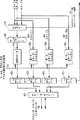
ここで、図面類さらに具体的には図3を参照すると、キャッシュ・コヒーレンシに対する、スヌーピング・アプローチを用いた多重プロセッサ・システムの総体的なベース・アーキテクチャが示されている。この好適な実施形態において、多重プロセッサ・システムは、各自のローカルL1データ及び命令用のキャッシュと、その各々に関連付けられたL2キャッシュ120a、…、120nとを備えたNヶのプロセッサ100a、…、100n(又はDCU1〜DCUNと名付けられたCPU群)から成る。主メモリ130は共用され、これをオンチップ又はチップ外に実装することができる。別の実施形態において、主メモリの代わりに、主メモリにアクセスを有する共用L3を使うことができる。該好適な実施形態において、プロセッサ・コア100a、…、100nは、PPC440又はPPC405のようなPowerPC(IBM社の登録商標)コアであるが、本発明の範囲から逸脱することなく他の任意のコアを用いることができ、あるいは、一つの多重プロセッサ・システムの中にさまざまなプロセッサを組み合わせて用いることもできる。プロセッサ・コア100a、…、100nは、システム・ローカル・バス150によって相互連結されている。
Referring now to the drawings and more specifically to FIG. 3, the overall base architecture of a multiprocessor system using a snooping approach to cache coherency is shown. In this preferred embodiment, the multiprocessor system includes
プロセッサに渡されるスヌープ要求の数を減らし、これにより、プロセッサ及びシステム・パフォーマンスに対するスヌーピングの影響を低減し、不必要なスヌープ要求によって消費されるアワーを削減するために、多重プロセッサ・システム10中の各プロセッサ・コア100a、…、100nのそれぞれに対しスヌープ・フィルタ140a、…、140nが具えられている。スヌーピング要求を伝送するため、該好適な実施形態は、通常従来技術のシステムで見られるようなシステム・バス150は使用せず、代わりに2点間相互接続160を実施し、これにより、各プロセッサの関連スヌープ・フィルタは、システム中の他のあらゆるプロセッサに関連付けられた各々のスヌープ・フィルタに直接連結される。かくして、スヌープ要求は、システム・ローカル・バスを介して伝送される他のメモリ要求のすべてから切り離され、しばしばシステムのボトルネックとなるバスの混雑を軽減する。一つのプロセッサに対するすべてのスヌープ要求は、そのスヌープ・フィルタ140a、…、140nに送られ、これらのフィルタについては、後記でさらに詳細を説明するように、同一のフィルタリング方法を具備した、又はいくつもの異なるフィルタリング方法を具備した、あるいはその2つの任意の組み合わせのいくつかのサブフィルタを含む。スヌープ・フィルタは各スヌープ要求を処理し、全要求のうち、プロセッサのキャッシュの中にある可能性のある一部だけをプロセッサに渡す。
To reduce the number of snoop requests passed to the processor, thereby reducing the impact of snooping on processor and system performance and reducing the time consumed by unnecessary snoop requests, A snoop
各プロセッサのスヌープ要求は、2点間相互接続160を用いて他のすべてのプロセッサのスヌープ・フィルタに直接接続される。これにより、異なったプロセッサからのいくつものスヌープ要求(書き込み及び無効化の試みからくる)を同時に行うことができる。システム・バスを使いバスが要求の逐次化を行う典型的なスヌーピング・アプローチと違って、これらの要求はもはや逐次化されない。すなわち、後記でさらに詳細を説明するように、複数のスヌープ要求をスヌープ・フィルタで同時に処理することが可能である。プロセッサは一つのスヌープ・ポートしか持たないので、スヌープ・フィルタに除去されなかったスヌープ要求はプロセッサに送られる順にキューに並べられる。しかしながら、プロセッサに渡される要求の数は、フィルタ前の全スヌープ要求の数よりもずっと少なく、キャッシュ・コヒーレンス実行がシステム・パフォーマンスに与える影響を軽減する。
Each processor's snoop request is directly connected to the snoop filter of all other processors using a point-to-
スヌープ・フィルタ・ブロック中に包含されるキューのキュー・オーバーフロー状態を防止するために、各々の2点間リンクに対し、トークンベースのフロー制御システムを実施し、同一時に競合する要求の数を制限する。該トークンベース・フロー制御によれば、各書き込み元は、それが直接2点間接続を有するスヌープ・フィルタ・ブロックの全ポートに対して使えるトークンさえ持っていれば、次の書き込み要求を送信することができ、該要求は、他のすべてのプロセッシング・ユニット及び関連するスヌープ・フィルタ・ブロックに対するスヌープ要求をも起動する。接続されている遠隔ポートの少なくとも一つに対し利用できるトークンがない場合、そのスヌープ・フィルタ・ポートに対し少なくとも一つのトークンが再度利用できるまでは、当該メモリ書き込み元からスヌープ要求を発信することはできない。 Implement a token-based flow control system for each point-to-point link to limit the number of competing requests at the same time to prevent queue overflow conditions for queues included in the snoop filter block To do. According to the token-based flow control, each writer sends the next write request as long as it has a usable token for all ports of the snoop filter block that have a direct point-to-point connection. The request can also trigger a snoop request for all other processing units and associated snoop filter blocks. If there is no token available for at least one of the connected remote ports, it is not possible to issue a snoop request from the memory writer until at least one token is available again for that snoop filter port. Can not.
図4は、キャッシュ・コヒーレンシのため、スヌーピング要求のための2点間相互接続を使うスヌーピング・アプローチを用いたベース多重プロセッサ・システムを含む本発明の別の実施形態を示しており、該実施形態では、スヌープ・フィルタは、L2キャッシュと主メモリ230との間に配置されている。この実施形態による多重プロセッサ・システムは、各々のデータ及び命令用ローカルL1キャッシュと、関連するL2キャッシュ220a、…、220nとを備えたNヶのプロセッサ200a、…、200n(又はDCU1〜DCUNと名付けられたCPU群)を含む。主メモリ230は共用され、これをオンチップ又はチップ外に実装することができる。別の実施形態において、主メモリの代わりに、主メモリにアクセスを有する共用L3キャッシュを使うことができる。プロセッサ200a、…、200nからのメモリ・アクセス要求のすべては、システム・ローカル・バス250を介して伝送される。図4に示された実施形態において、多重プロセッサ・システム中のプロセッサの各々は、それぞれのスヌープ・フィルタ240a、…、240nと対になっている。この好適な実施形態では、スヌープ要求を転送するのに2点間相互接続が使われ、システム・バスの混雑が軽減されている。この2点間相互接続スキーム260では、各プロセッサに関連付けられたスヌープ・フィルタは、システム中の他のあらゆるプロセッサに関連付けられた各々のスヌープ・フィルタに直接連結される。一つのプロセッサに対するスヌープ要求はすべてそのプロセッサのスヌープ・フィルタに送られ、これが各々のスヌープ要求を処理し、全要求のうち適切な一部だけをプロセッサに渡す。この実施形態においては、スヌープ要求はL2キャッシュ・レベルで(図3に示した前の実施形態におけるようなL1ではなく)フィルタされるが、本発明は、任意のキャッシュ・レベルに適用でき、本発明の範囲から逸脱することなく他のレベルのキャッシュ階層に対し用いることができる。
FIG. 4 illustrates another embodiment of the present invention that includes a base multiprocessor system using a snooping approach that uses a point-to-point interconnect for snooping requests for cache coherency. The snoop filter is disposed between the L2 cache and the
ここで図5を参照すると、本発明によるスヌープ・フィルタのハイレベルのブロック図が示されている。1からNまでの他のすべてのプロセッサからのスヌープ要求は、専用の2点間相互接続入力ライン300a、…、300nを介してスヌープ・ブロック310に送られる。スヌープ・ブロック310は、入来するスヌープをフィルタし、適切なサブセットをプロセッサ・スヌープ・インタフェース340を介してプロセッサ320に送る。さらに、スヌープ・ブロック310は、プロセッサとL1キャッシュとのブロック320からL2キャッシュ330へのメモリ・アクセス要求のすべてをモニタする。これらは、L1キャッシュ中の欠落に対する要求だけである。スヌープ・ブロックは、読み取りアドレスをすべてモニタし、これに応じ信号360及び362を制御してそのフィルタを更新する。
Referring now to FIG. 5, a high level block diagram of a snoop filter according to the present invention is shown. Snoop requests from all
図6は、図5に示されたスヌープ・ブロック310のハイレベル概略図を示す。図6に示されるように、スヌープ・ブロック310は、並行して動作し各々がNヶのメモリ書き込み元(プロセッサ又はDMAエンジンのサブシステムなど)の一つだけに専任する複数(「Nヶ」)のポート・スヌープ・フィルタ400a、…、400nを含む。ポート・スヌープ・フィルタ400a、…、400nの各々は、直接2点間接続された単一の送信元からのスヌープ要求をその専用入力ライン410a、…、410nに受信する。後記で説明するように、一つのポート・スヌープ・フィルタには、さまざまなスヌープ・フィルタ方法を含めることができる。スヌープ・ブロック310は、ストリーム・レジスタ・ブロック430及びスヌープ・トークン制御ブロック426をさらに含む。加えて、各ポート・スヌープ・フィルタ400a、…、400nは、関連するプロセッサからの、プロセッサのL1レベル・キャッシュ中の欠落に対するメモリ読み取りアクセス要求412をすべてモニタする。また、この情報は、後記でさらなる詳細を説明するように、ストリーム・レジスタ・ブロックの使用のために提供される。
FIG. 6 shows a high level schematic of the snoop block 310 shown in FIG. As shown in FIG. 6, the snoop
作動において、ポート・スヌープ・フィルタ400a、…、400nは、入来するスヌープ要求を処理し、全スヌープ要求からのサブセットを、各スヌープ・ポートに対して各一つのキューが対応するスヌープ・キュー420a、…、420nのそれぞれに送る。スヌープ・キュー420全部の間を調停し、スヌープ・キュー420からのスヌープ要求すべてを適正に逐次化するキュー・アービトレーション・ブロック422が具備されている。スヌープ・キューのオーバーフロー状態を検知するロジックが具えられ各キューの状態が、遠隔メモリ書き込み元からのスヌープ要求の流れを制御するスヌープ・トークン制御ユニット426に入力される。プロセッサ又はDMAエンジンなどのメモリ書き込み元は、すべてのスヌープ・フィルタに対し利用できるトークンを持ってさえいれば、メモリに対し書き込みを、全スヌープ・フィルタに対してはスヌープ要求を提起することができる。プロセッサが、書き込みを提起するため、相手からの利用可能なトークンを必要としないスヌープ・フィルタは、プロセッサ自体のローカル・スヌープ・フィルタしかない。このメカニズムによって、スヌープ・キューがオーバーフローしないことが確実になる。スヌープ要求は、調停機能422に選定されたスヌープ・キューから、プロセッサ・スヌープ・インタフェース408を介してプロセッサに送られる。
In operation, port snoop
図7は、一つのスヌープ・ポート・フィルタ400のハイレベル概略図を示す。スヌープ・ポート・フィルタ・ブロック400は、さまざまなフィルタリング・アルゴリズムを実行する複数のフィルタ・ユニットを含む。この好適な実施形態では、各々が異なるフィルタ・アルゴリズムを実行する3つのスヌープ・フィルタ・ブロック440、444、及び448が並行して動作している。該スヌープ・フィルタ・ブロックは、スヌープ・キャッシュ440、ストリーム・レジスタ・チェック・ユニット444、及びレンジ・フィルタ448と名付けられている。一つの実施形態において、並列のスヌープ・フィルタ・ブロックの各々は、単一の発信元からの同一のスヌープ要求410を同時に各自の入力部に受信する。さらに、スヌープ・キャッシュ440は、プロセッサからのL1レベル・キャッシュ中の欠落に対するメモリ読み取りアクセス要求412をすべてモニタし、ストリーム・レジスタ・チェック・ユニット444は、図6に示されたストリーム・レジスタ・ユニット430から状態入力432を受信する。
FIG. 7 shows a high level schematic of one snoop
該好適な実施形態によれば、スヌープ・キャッシュ・ブロック440は、スヌープ要求の現在時の局所的特性に基づいたアルゴリズムを使ってスヌープ要求410をフィルタする、すなわち、特定のロケーションに対し一つのスヌープ要求が行われたならば、同じロケーションへの別の要求は迅速に行える可能性があるということである。スヌープ・キャッシュは、ローカル・キャッシュに対し行われるあらゆるロードをモニタし、必要に応じその状態を更新する。ストリーム・レジスタ・チェック・ブロック444は、現在のローカル・キャッシュ内容のサブセットを判断するアルゴリズムを使って、スヌープ要求410をフィルタする。キャッシュ内容の概要値がストリーム・レジスタ・ブロック430(図6)に含まれており、ストリーム・レジスタ状態432は各スヌープ・ポート・フィルタ400に転送される。この状態に基づいて、各新規スヌープ要求410に対して、スヌープ・アドレスをローカル・キャッシュに含めることができる可能性が判断される。スヌープ・ポート・フィルタ中の第三のフィルタリング・ユニットは、レンジ・フィルタ448である。このフィルタリング・アプローチのため、2つのレンジ・アドレスが指定される、すなわち最小レンジ・アドレスと最大レンジ・アドレスとである。スヌープ要求のフィルタリングは、まず、当該スヌープ要求がこれらの2つのレンジ・アドレスで規定されたアドレス範囲内にあるかどうか判断することから行われる。この条件を満たす場合、スヌープ要求は廃棄され、そうでなければ、スヌープ要求は判断ロジック・ブロック450に送られる。逆に、要求がアドレス範囲内に入っていれば送り、そうでなければ廃棄することもでき、これも本発明の要旨の範囲内である。具体的に、判断ロジック・ブロック450は、3つのフィルタ・ユニットのすべて、440、444、及び448の結果456を、各個別スヌープ・フィルタ・ユニットを有効又は無効にする制御信号454とともに受信する。対応する制御信号が有効化されているスヌープ・フィルタ・ユニットの結果だけが各フィルタリング判断の対象となる。フィルタリング・ユニット440、444、又は448のいずれかが、スヌープ要求410を廃棄すべきと判断すればそのスヌープ要求は廃棄される。判断ロジック・ユニットの結果出力は、スヌープ要求を対応するスヌープ・キュー452に加えるか、あるいは、スヌープ要求を廃棄し、スヌープ・トークン458を廃棄されたスヌープ要求を発行した遠隔プロセッサ又はDMAユニットに返却するかのいずれかとなる。
According to the preferred embodiment, the snoop cache block 440 filters the snoop
該好適な実施形態においては、上記のアルゴリズムを実行する3つのフィルタリング・ユニットだけがポート・スヌープ・フィルタに含まれているが、当業者は、本発明の範囲から逸脱することなく、他の任意の数のスヌープ・フィルタ・ユニットを一つのポート・スヌープ・フィルタに含めることができること、又はポート・スヌープ・フィルタ中で何らかの他のスヌープ・フィルタ・アルゴリズムを実行できること、又はスヌープ・アルゴリズムの組み合わせが可能なことをよく理解しているであろう。 In the preferred embodiment, only three filtering units that perform the above algorithm are included in the port snoop filter, but those skilled in the art will recognize that any other option without departing from the scope of the present invention. Any number of snoop filter units can be included in a port snoop filter, or any other snoop filter algorithm can be run in a port snoop filter, or a combination of snoop algorithms is possible I understand that well.
図8及び9は、図6のスヌープ・フィルタ310の2つの別な実施形態のハイレベル概略図を示す。図6に関連して前に説明したように、スヌープ・ブロックには、多様なフィルタリング・アプローチ、同一のフィルタリング・アプローチ、又はこれら2つの組合せを用いた複数のスヌープ・フィルタを含めることができる。図8に示されるように、Nヶのポート・スヌープ・フィルタ460a、…、460nは、一つずつが並行してNヶの遠隔メモリ書き込み元の各々に対応して動作している。ポート・スヌープ・フィルタ460a、…、460nの各々は、2点間接続された専任の発信元からのスヌープ要求を、それぞれの入力ライン462a、…、462nに受信する。さらに、各スヌープ・フィルタ460a、…、460nは、ローカル・プロセッサの、L1レベル・キャッシュ中の欠落に対するメモリ・ロード要求464のすべてをモニタする。また、スヌープ・ブロックの他のユニットからの他の信号も、実行されているフィルタ・アルゴリズムが要求する場合にはポート・スヌープ・フィルタに供給する必要があろう。必要とされる信号の内容は、一つのポート・スヌープ・フィルタ460内で実行されている一つ以上のスヌープ・フィルタ・アルゴリズムによって決まる。さらに、全ポート・スヌープ・フィルタが、必ずしも同一セットのフィルタリング・アルゴリズムを実行する必要はないことを理解しておくべきである。
8 and 9 show high-level schematics of two alternative embodiments of the snoop
ポート・スヌープ・フィルタ460a、…、460nは入来するスヌープをフィルタし、フィルタ除去されなかったスヌープ要求の適切なサブセットを、それぞれのキュー466a、…、466n中を経由してキュー・アービトレーション・ブロック468に送る。ここでスヌープ要求は逐次化され、次の共用スヌープ・フィルタ470に送られ、該共用フィルタは遠隔メモリ書き込み元すべてからの入力を取り扱う。この共用スヌープ・フィルタ470は、渡されたスヌープ要求のすべてを処理し、全要求のサブセットをスヌープ・キュー472に送る。スヌープ要求は、スヌープ・キュー472からプロセッサ・スヌープ・インタフェース474を介してプロセッサに送られる。なお、図8に示された構成に換えて、共用スヌープ・フィルタ470を複数にしたり省略することも可能である。複数共用フィルタの場合、これらフィルタを並列にも直列にも(この場合、例えば一つのフィルタの出力が次の入力となる)配列することができる。フィルタが複数の発信元からの入力を扱う(すなわち複数発信元の間で共用されている)場合、該フィルタはそれ自体の入力キュー及び調停機能を具え、スヌープ要求を逐次化する必要がある。最終的に順序付けされた全スヌープ要求のサブセットはスヌープ・キュー472に置かれ、スヌープ要求は、プロセッサ・スヌープ・インタフェース474を介してプロセッサに送られる。随意により、スヌープ・キューが満杯になったとき、それを示すスヌープ・キュー満杯表示信号476を具え、スヌープ・キューの中のスヌープの数が所定のレベルを下回るまで、一部又はすべてのメモリ書き込み元がさらなるスヌープ要求を発行するのを止めさせる。
Port snooping filters 460a,..., 460n filter incoming snoops, and pass a suitable subset of unfiltered snoop requests through respective queues 466a,. To 468. Here, the snoop requests are serialized and sent to the next shared snoop
同様に、図9は、スヌープ・ブロック310中のスヌープ・フィルタの異なった編成による別の実施形態を示す。各々が遠隔メモリ書き込み元(スヌープ・フィルタが付随されるプロセッサは除く)の一つからのスヌープ要求だけを受信するNヶのポート・スヌープ・フィルタ480a、…、480nは並行して動作する。各ポート・スヌープ・フィルタ480a、…、480nは、そのそれぞれの入力ラインに、単一の発信元だけからのスヌープ要求482a、…、480nをそれぞれ受信する。共用スヌープ・フィルタ484は、ポート・スヌープ・フィルタ・デバイス480a、…、480nと並列に連結されている。別の実施形態では、複数の共用スヌープ・フィルタを並列に配置することができる。共用スヌープ・フィルタ484は、Nヶすべての遠隔メモリ書き込み元からの入力を取り扱う。複数の入力を受信するので、共用フィルタ484は、スヌープ要求を逐次化するためにそれ自体の入力キュー486及びキュー・調停機能488を有する。さらに、図9に示された実施形態において、ポート・スヌープ・フィルタ480a、…、480nのすべて及び共用スヌープ・フィルタ484は、ローカル・プロセッサからの、L1レベル・キャッシュ中の欠落に対するメモリ読み取りアクセス要求490をすべてモニタする。スヌープ・フィルタ480a、…、480n及び484は、入来するスヌープ要求をフィルタし、フィルタ除去されなかった適切なサブセットを次の共用スヌープ・フィルタの入力キュー492a、…、492nに送る。次いで、フィルタ除去されなかったスヌープ要求はキュー・調停機能494によって逐次化され、プロセッサ・スヌープ・インタフェース496を介してプロセッサに送られる。スヌープ・キュー・デバイス492a、…、492nの一つ又は486が満杯の場合、スヌープ・キュー満杯表示498が作動され、スヌープ・キューの中のスヌープの数が所定のレベルを下回るまで、すべての(又は一部の)メモリ書き込み元がさらなるスヌープ要求を発行するのを止めさせる。
Similarly, FIG. 9 shows another embodiment with a different organization of snoop filters in the snoop
次に図10を参照すると、スヌープ・フィルタ・ブロックのさらなる実施形態310が示されている。該ブロックは、ポート・スヌープ・フィルタ400、(図8及び9の)460a、…、460n、及び480a、…、480nに対応する、Nヶのポート・スヌープ・フィルタ500a、…、500nを包含する。各ポート・スヌープ・フィルタ500a、…、500nは、スヌープ・キャッシュ・デバイス502a、…、502n、及びスヌープ・チェック・ロジック504a、…、504nを含む。スヌープ・キャッシュ・デバイス502a、…、502nは、一つの発信元からの最新のスヌープ要求の経過を追跡記録するスヌープ・フィルタリング・アルゴリズムを実行し、このスヌープ要求の発信元を、別のプロセッサ、DMAエンジン、あるいは何か他のユニットとすることができる。一つのの発信元からの各新規スヌープ要求に対し、該スヌープ要求のアドレスが、スヌープ・チェック・ロジック・ブロック504中のスヌープ・キャッシュと照合される。この対比結果が一致すれば、すなわちスヌープ・キャッシュ中に該スヌープ要求が見つかれば、スヌープされたデータはプロセッサのローカルL1キャッシュ中にないことが保証される。従って、スヌープ要求は、スヌープ・キュー506及びスヌープ・キュー・調停機能508には送られない。スヌープ・キャッシュ502a、…、502nの中に現下のスヌープ要求に対し一致するものが見つからなければ、信号514a、…、514nを使って該スヌープ要求のアドレスがスヌープ・キャッシュに追加される。同時に、スヌープ要求はスヌープ・キュー506に送られる。
Referring now to FIG. 10, a
また、スヌープ・キャッシュ・デバイス502a、…、502nのすべては、ローカル・プロセッサから、読み取りアドレス及び要求を受信し、該メモリ読み取りアクセス・アドレスをスヌープ・キャッシュ502a、…、502n中のエントリと対比する。要求がスヌープ・キャッシュ中のエントリの一つと合致すれば、そのエントリは、キャッシュ・ラインがプロセッサの第一レベルのキャッシュに配置されることになり、スヌープ・キャッシュからは除去される。該好適な実施形態において、並行して動作し、各々が一つの遠隔メモリ書き込み元からのスヌープ要求を追跡記録する複数のスヌープ・キャッシュが用いられる。フィルタリングの後、スヌープ要求のフィルタ除去されなかった部分を、実施形態に応じて、次のポート・スヌープ・フィルタに送るなり、又は一つ以上の共用スヌープ・フィルタのキューに入れるなり、又はプロセッサ・インタフェースのスヌープ・キューに置くなりすることができる。
Also, all of the snoop
なお、単一のスヌープ・キャッシュ・デバイス502は、各エントリが2つのフィールド、すなわちアドレス・タグ・フィールドと有効ライン・ベクトルとを有するMヶのキャッシュ・ライン(エントリ)の内部編成を含む。スヌープ・キャッシュのアドレス・タグ・フィールドは、通常、ローカル・プロセッサのL1キャッシュのアドレス・タグと同じではなく、これより、有効ライン・ベクトル中に表現されるビット数の分短い。具体的には、有効ライン・ベクトルは、いくつかの連続するキャッシュ・ラインの群を符号化し、すべてのラインが、対応するアドレス・タグ・フィールドによって表現される同一の上位ビットを共用している。しかして、2nの連続するL1キャッシュ・ラインを符号化するためアドレスの最下位ビットn桁が使われる。nがゼロの極端な場合、スヌープ・キャッシュ中の全エントリはただ1本のL1キャッシュ・ラインで表わされる。この場合、有効ライン・ベクトルは「バリッド」ビットに対応するただ一つのビットとなる。 Note that a single snoop cache device 502 includes an internal organization of M cache lines (entries), each entry having two fields: an address tag field and a valid line vector. The address tag field of the snoop cache is usually not the same as the address tag of the local processor L1 cache, and is shorter by the number of bits represented in the valid line vector. Specifically, a valid line vector encodes a group of several consecutive cache lines, and all lines share the same high order bit represented by the corresponding address tag field. . Thus, n least significant bits of the address are used to encode 2n consecutive L1 cache lines. In the extreme case of n being zero, all entries in the snoop cache are represented by only one L1 cache line. In this case, the effective line vector is a single bit corresponding to the “valid” bit.
スヌープ・キャッシュ中のアドレス・タグ・フィールドのサイズは、L1キャッシュ・ラインのサイズ及び有効ライン・ベクトルの符号化に使われたビットの数により決まる。ある実施形態において、32ビットのアドレス長(31:0)、L1キャッシュ・ラインが32バイトの長さ、及び32ビットの有効ライン・ベクトルに対し、アドレス・ビット(31:10)がアドレス・タグ・フィールドとして使われ、(ビット31は最上位)、アドレス・ビット(9:5)中に有効ライン・ベクトルが符号化され、アドレス・ビット(4:0)は、これらがキャッシュ・ラインのバイト・オフセットを符号化しているので無視される。例として、3つの異なるメモリ書き込み元(N=3)に対する3つのスヌープ・キャッシュを下記に示すが、これら各スヌープ・キャッシュは、M=4のエントリを有し、該エントリの左側にアドレス・タグ・フィールドがあり、アドレスの5つのビットは、32の連続するキャッシュ・ラインを追跡するための有効ライン・ベクトルの符号化に使われる。

この例において、要求元1のエントリ1では、スヌープ・キャッシュは、16進アドレス01c019ecが最近に無効化され、おそらくL1キャッシュ中にあり得ないことを記録している。従って、同じキャッシュ・ラインに対する次のスヌープ要求はフィルタ除去(廃棄)されることになる。同様に、書き込み元1のエントリ4によって、キャッシュ・ライン・アドレス01407ff7及び01407ff8に対するスヌープ要求がフィルタ除去されることになる。
In this example, in
次に、図11を参照すると、単一スヌープ元に対するスヌープ・キャッシュ・デバイスを実行するスヌープ・フィルタの制御フローが示されている。作業開始において、ステップ600に示されるように、スヌープ・キャッシュ内のMヶラインのすべてがリセットされる。スヌープ元iからの新しいスヌープ要求が受信されると、該スヌープ要求のアドレスは、「アドレス・タグ」フィールド526の中と、有効ライン・ベクトル524にアクセスするため使われるビットの中とに構文分解される。スヌープ要求の有効ライン・ベクトルは、アドレス・タグ・フィールドに一致するアドレス・ビットを持つ各L1キャッシュに対応する一つのビットだけを有する。これはステップ602で行われる。ステップ604において、スヌープ要求の「タグ」フィールドは、スヌープ元iに関連するスヌープ・キャッシュ中のすべてのタグ・フィールドに対して照合される。スヌープ要求のアドレス・タグがスヌープ・キャッシュに格納されたアドレス・タグの一つと同じである場合、該アドレス・タグ・フィールドは、スヌープ・キャッシュ中にヒットを有する。この後、ヒットが検知されたスヌープ・キャッシュ・エントリの有効ライン・ベクトルは、スヌープ要求の有効ライン・ベクトルと対比される。スヌープ・キャッシュ・ライン中の有効ライン・ベクトルのビットが、スヌープ要求の有効ライン・ベクトル中のビット・セットに一致してセットされていれば、有効ライン・ベクトルも同様にヒットを有する。一つの好適な実施形態において、ビット・オペランドに対し論理演算を行うことによって、有効ライン・ベクトルのチェックが実施される。しかして、例えば、スヌープ要求の有効ライン・ベクトルとスヌープ・キャッシュ・ラインの有効ライン・ベクトルとをAND演算し、結果がゼロになるかどうかを確認することによって有効ライン・ベクトルのチェックを行うことができる。なお、本発明の範囲から逸脱することなく、他の実施方法を追加して用いることができよう。さらに、有効ライン・ベクトルのヒットのチェックは、アドレス・タグのヒットのチェックと並行して実施することができる。
Referring now to FIG. 11, a control flow for a snoop filter that performs a snoop cache device for a single snoop source is shown. At the start of work, as shown in
ステップ606において、「タグ」フィールドが一致し、且つ有効ライン・ベクトル中に一致するビットがセットされているかどうかの判断が行われる。「タグ」フィールドが一致し、且つ有効ライン・ベクトル中に対応するビットがセットされていれば、ステップ606に示されるように、スヌープ要求はキャッシュ中にないことが保証される。しかして、当該スヌープ要求は、キャッシュには送られず、ステップ608に示されるようにフィルタ除去される。
In
それとは別に、「タグ」フィールドはスヌープ・キャッシュ中をヒットしたが有効ライン・ベクトル中のビットが一致していないか、あるいは、スヌープ・キャッシュ中でタグがヒットしない場合、このことは、ラインがキャッシュにあり得ることを示している。従って、スヌープ要求は、ステップ612に示されるように、スヌープ・キュー中に置かれて、キャッシュに送られる。また、ステップ610に示されるように、このスヌープ要求は、新しいエントリとしてスヌープ・キャッシュに加えられる。
Alternatively, if the "Tag" field hits in the snoop cache but the bits in the valid line vector do not match, or if the tag does not hit in the snoop cache, this means that the line is Indicates that it can be in the cache. Thus, the snoop request is placed in the snoop queue and sent to the cache, as shown in
次に図12を参照すると、スヌープ・キャッシュ中に新しい情報を追加するプロセスを記載した、ステップ610(図11)の詳細が示されている。これは、以下に説明するように、いくつかのタスクによって達成される。ステップ614において、まず、アドレス・タグが、既にスヌープ・キャッシュの中に格納されているかどうか(すなわち、アドレス・タグがヒットしたか)を判定する。このステップにおいて、ステップ602(図11)で計算された情報を使うことができる。アドレス・タグがヒットした場合には、プロセスはステップ624に進み、そこでスヌープ要求に一致する選定されたスヌープ・キャッシュ・エントリの有効ライン・ベクトル中のビットがセットされる。ステップ614においてアドレス・タグ・チェックがヒット無しであった場合、その新しいアドレス・タグに対して新規スヌープ・キャッシュ・エントリを割り当てなければならず、プロセスは616に進み、スヌープ・キャッシュの中に利用可能な空きエントリがあるかどうかが判断される。空きエントリが利用可能と判断された場合、ステップ620で示されるように最初の利用可能空きエントリが選定される。スヌープ・キャッシュに利用可能な空きエントリが無い場合、ステップ618に示されるように、スヌープ・キャッシュ中の有効エントリの一つが置換え用に選定される。この置換え基準については、ラウンド・ロビン処理、最近最少使用、ランダム、又は、本発明の範囲から逸脱することなく当業者にとって公知の他の置換え基準とすることができる。ステップ622に進み、次いで新規のアドレス・タグが選定されたスヌープ・キャッシュ・ラインに書き込まれ、対応する有効ライン・ベクトルは消去される。次いで、ステップ624に示されるように、スヌープ要求の有効ライン・ベクトル中のビット・セットに一致させて、選定されたスヌープ・キャッシュ・エントリの有効ライン・ベクトル中にビットがセットされる。
Referring now to FIG. 12, details of step 610 (FIG. 11) are shown that describes the process of adding new information in the snoop cache. This is accomplished by several tasks as described below. In
さらに別の実施形態では、スヌープ要求がスヌープ・キャッシュの中でヒットしたかミスしたかだけに基づいて新しい情報をスヌープ・キャッシュをスヌープ・キャッシュに加えることはせず、代わりに、スヌープ・キャッシュ・ライン全体であれ、有効ライン・ベクトル中に単一ビットをセットするだけのことであれ、新しい値の追加は、判断ロジック・ブロック450(図7)の判断に基づいて行う。この実施形態においては、判断ロジック・ブロックがスヌープ要求をフィルタ除去しない場合にだけ、新しい情報がスヌープ・キャッシュに加えられる。スヌープ・ポート・フィルタ・ブロック400(図7)中の他のどれかのフィルタがスヌープ要求をフィルタ除去した場合、(すなわち、データがローカルL1キャッシュに無いと判断した場合)、スヌープ・キャッシュに新しい情報は加えられないが、作業ステップはスヌープ・キャッシュのヒットの場合と同じである。この実施形態の利点は、冗長な情報の格納が少なくなるのでスヌープ・キャッシュの処理パフォーマンスが良くなることである。 In yet another embodiment, no new information is added to the snoop cache based on whether the snoop request was hit or missed in the snoop cache, instead the snoop cache Whether the entire line or just a single bit is set in the valid line vector, the addition of a new value is based on the decision of decision logic block 450 (FIG. 7). In this embodiment, new information is added to the snoop cache only if the decision logic block does not filter the snoop request. If any other filter in the snoop port filter block 400 (FIG. 7) filters out the snoop request (ie, determines that the data is not in the local L1 cache), it is new to the snoop cache. No information is added, but the work steps are the same as for a snoop cache hit. The advantage of this embodiment is that the processing performance of the snoop cache is improved because redundant information is stored less.
次に図13を参照すると、スヌープ・キャッシュからエントリを除去するための制御フローが示されている。プロセッサの、ローカルL1レベル・キャッシュ中の欠落に対するメモリ読み取りの各要求に対して、メモリ要求のアドレスは、全スヌープ要求元に関連する、すべてのスヌープ・キャッシュ中の全エントリと照合される。ステップ630において、メモリ読み取り要求のアドレスは、アドレス・タグ・フィールドの中及び有効ライン・ベクトルの符号化に使われるビットの中に構文分解される。これは、ステップ630で行われる。ステップ632において、一つ以上のタグ・ヒットがあるかどうかの判断が行われる。これは、メモリ要求の「タグ」フィールドを、全スヌープ元に関連するすべてのスヌープ・キャッシュ中の全タグ・フィールドと照合することによって遂行される。該タグ・チェックがミスの場合、このアドレスはフィルタ除去されず、何もしてはならない。しかして、制御フローはステップ630にループ・バックし、プロセッサからの次のキャッシュ欠落読み取りを待つ。
Referring now to FIG. 13, the control flow for removing entries from the snoop cache is shown. For each request of the processor to read a memory for a drop in the local L1 level cache, the address of the memory request is checked against all entries in all snoop caches associated with all snoop requesters. In
ステップ632に戻ると、アドレス・タグの全スヌープ・キャッシュとの対比から一つ以上のヒットが得られたと判断された場合、ヒットされたすべてのスヌープ・キャッシュから情報を除去しなければならない。そこで、ステップ634において、メモリ・読み取りアドレスの適切な下位ビットは、有効ライン・ベクトルに復号され、ステップ635に示されるように、ヒットされたスヌープ・キャッシュ・エントリの有効ライン・ベクトルと対比される。次に、ステップ636に進み、読み取りアドレス・ベクトル中の固有のビット・セットが、同様にスヌープ・キャッシュの有効ライン・ベクトル中にセットされているかどうかが判断される。このような有効ライン・ベクトルのヒットがない場合(アドレス・タグ・フィールドのヒットの如何を問わず)、このメモリ・アドレスはフィルタ除去されず、該特定のスヌープ・キャッシュ中の何も変更してはならない。かくして、制御フローはステップ640に進み、すべてのアドレス・タグのヒットの処理が済んだかどうかをチェックし、まだであれば、プロセスはステップ635に戻る。
Returning to step 632, if it is determined that one or more hits have been obtained from contrasting the address tag with all snoop caches, the information must be removed from all hit snoop caches. Thus, in
また一方、ステップ636で、読み取りアドレス・ベクトルが有効ライン・ベクトル中でヒットしたと判断されれば、該読み取りアドレスはフィルタ除去されることになる。該メモリ読み取りアドレスは第一レベルのキャッシュにロードされることになるので、対応する有効ライン・ベクトルのビットは消去されねばならない。この有効ライン・ベクトルからの対応ビットの消去はステップ638で行われる。有効ライン・ベクトルからの対応ビットの除去の後で、該有効ライン・ベクトルのビット・セットの数がゼロになる場合、スヌープ・キャッシュからアドレス・タグ・フィールドがさらに除去され、エントリが空になる。次にステップ640に示されるように、有効ライン・ベクトル・ビットのチェック、その消去、及びアドレス・タグの消去の同じプロセスが、必要に応じ、ローカルL1キャッシュの欠落に対する要求であるメモリ読み取り要求をヒットした、スヌープ・キャッシュすべてに対して繰り返し行われる。ヒットしたアドレス・タグ・ラインすべてが処理された状態になっているかどうかがステップ640でチェックされる。キャッシュ・ラインのすべてがチェックされたならばプロセスはステップ630に戻る。
On the other hand, if it is determined in
さらに別の実施形態において、当該ローカル・メモリ要求は、全スヌープ・キャッシュ中の全アドレス・タグに対し同時に対比される。同時に、ローカル・メモリ要求の有効ライン・ベクトルの符号を、ヒットがあった全スヌープ・キャッシュ中の全有効ライン・ベクトルと一せいに対比することができる。次いで、これら2つの結果−アドレス・タグのヒット及び有効ライン・ベクトルのヒット−の組合せにより、対応する有効ライン・ベクトルのビットを除去しなければならないすべてのスヌープ・キャッシュ・ラインを判定し、全スヌープ・キャッシュ中のヒットしたキャッシュ・ラインから、これらビットのすべてを同時に除去することができる。 In yet another embodiment, the local memory request is contrasted against all address tags in all snoop caches simultaneously. At the same time, the sign of the valid line vector of the local memory request can be contrasted with all valid line vectors in the full snoop cache where there was a hit. The combination of these two results--address tag hit and valid line vector hit-- then determines all snoop cache lines from which the corresponding valid line vector bits must be removed, and all All of these bits can be removed simultaneously from the hit cache line in the snoop cache.
次に図14を参照すると、ストリーム・レジスタを実装したスヌープ・フィルタ・デバイスのブロック図が示されている。一つの好適な実施形態において、スヌープ・フィルタ・ユニットは以下のエレメントを含む:2つのストリーム・レジスタ及びマスク・セット700、スヌープ・チェック・ロジック・ブロック702、キャッシュ・ラップ検知ロジック・ブロック706、ストリーム・レジスタ選択ロジック・ブロック704、スヌープ要求キュー703、及び、プロセッサ・調停及び多重化ロジック710。後述でさらに詳細を説明するように、キャッシュ中に無いものを追跡するスヌープ・キャッシュ・フィルタと違って、ストリーム・レジスタ及びマスク・セット700は、プロセッサのキャッシュにロードされた最新のデータを追跡記録する。さらに正確には、ストリーム・レジスタは、少なくともキャッシュ中にあるラインを追跡記録するが、一部のラインについて、実際はキャッシュに無いのに、キャッシュ格納されていると想定することがある。しかし、一部の不必要なスヌープ要求をキャッシュに送ったとしても正確さに影響することはない。
Referring now to FIG. 14, a block diagram of a snoop filter device that implements a stream register is shown. In one preferred embodiment, the snoop filter unit includes the following elements: two stream registers and mask set 700, snoop
ストリーム・レジスタの中心はストリーム・レジスタ700自体である。キャッシュが新しいラインをロードする毎にこれらレジスタの一つが更新され、新ラインは適切な制御信号716とともにストリーム・レジスタに渡される。図14中のストリーム・レジスタ選択ロジック・ブロック704は、特定のレジスタを選択し、現在のストリーム・レジスタの状態と、信号716中のキャッシュの中にロードされている新しいラインのアドレスとに基づいて、該レジスタを更新する役割を果たす。
The center of the stream register is the
作動において、Nヶの遠隔プロセッサの一つから受信されたスヌープ要求は、図15の右側に示された信号714として着信する。スヌープ・チェック・ロジック・ブロック702は、着信したスヌープ要求714のアドレスをストリーム・レジスタ700の状態と対比して該スヌープ要求がキャッシュにある可能性を判断するポート・フィルタのセットを含む。可能性がある場合、該要求はスヌープ要求キュー703に送られ、そこで、実際のキャッシュ・スヌープとしてキャッシュに送られるのを待つ。図14の待ち行列構造では、Nヶの遠隔プロセッサの各々は専用のスヌープ要求キュー703を有し、最大のスヌープ要求レート設定ができるようになっており、大きな数のスヌープ要求をフィルタ除去し、エンキューの対象にならないようにする。本発明の一般的範囲から逸脱することなく、違った待ち行列構造にすることも可能である。
In operation, a snoop request received from one of the N remote processors arrives as
調停及び多重化ロジック・ブロック710は、単に、Nヶのスヌープ要求キュー703の間で、キャッシュのスヌープ・インタフェースを適正に割り振りし、すべての要求に対し転送の進捗を保証する。
Arbitration and multiplexing
以下に、一つのストリーム・レジスタがどのように更新されるのかを説明する。ストリーム・レジスタは、実際は「ベース」及び「マスク」のレジスタ対とバリッド・ビットとを含む。ベース・レジスタは、ストリーム・レジスタによって表されるキャッシュ・ラインのすべてに共通なアドレス・ビットを追跡記録し、対応するマスク・レジスタは、どのビットがあるかを追跡記録する。バリッド・ビットは単に、ストリーム・レジスタが使用中であることと、遠隔スヌープ要求714をフィルタするかどうかを決める際にスヌープ・チェック・ロジック・ブロック702が参照するのは当該ストリーム・レジスタであることとを示している。以下の例示をわかりやすくするために、32バイトのキャッシュ・ライン・サイズを備えた232バイトのアドレス・スペースを考えてみる。この場合、キャッシュ・ライン・ロード・アドレスは27ビット長で、ストリーム・レジスタのベース及びマスク・レジスタの長さは27ビット長である。
The following describes how one stream register is updated. The stream register actually includes a “base” and “mask” register pair and a valid bit. The base register keeps track of the address bits common to all of the cache lines represented by the stream registers, and the corresponding mask register keeps track of which bits are present. The valid bit is simply that the stream register is in use and that the snoop
まず、バリッド・ビットはゼロにセットされ、ストリーム・レジスタが使用されていないことが示され、ベース及びマスク・レジスタの内容は意味を持たない。最初のキャッシュ・ライン・ロード・アドレスがこのストリーム・レジスタに加えられたとき、バリッド・ビットは1にセットされ、ベース・レジスタは該ライン・アドレスにセットされ、マスク・レジスタの全ビットが1にセットされ、これでベース・レジスタ中のすべてのビットが有効になる。すなわち、ベース・レジスタに格納されたアドレスにちょうど一致するアドレスが、キャッシュ中にあると見なされ、ビットが一つでも異なればそのアドレスは不在とされる。例えば、第1キャッシュ・ライン・ロード・アドレスが、0x1708fb1(接頭部の0xは16進数であることを示す)として与えられれば、ロードの後のストリーム・レジスタの内容は、
ベース=0x1708fb1 マスク=0x7ffffff バリッド=1
となる。
First, the valid bit is set to zero, indicating that the stream register is not used, and the contents of the base and mask registers are meaningless. When the first cache line load address is added to this stream register, the valid bit is set to 1, the base register is set to the line address, and all bits in the mask register are set to 1. Set so that all bits in the base register are valid. That is, an address that exactly matches the address stored in the base register is considered to be in the cache, and if even one bit is different, the address is absent. For example, if the first cache line load address is given as 0x1708fb1 (prefix 0x indicates hexadecimal), the contents of the stream register after the load is
Base = 0x1708fb1 Mask = 0x7ffffff Valid = 1
It becomes.
次に、このストリーム・レジスタに第2のキャッシュ・ライン・ロード・アドレスが加えられると、第2のアドレスがベース・レジスタと対比され、どのビットが異なるかが判断される。ついで、マスク・レジスタが更新され、異なる位置のマスクの中のビットがゼロにされる。しかして、これらのゼロは、ベース・レジスタの対応ビットは「判断外」であり、どの値(ゼロ又は1)をも取れると見なすことができることを示す。従って、これらのビットは、ストリーム・レジスタとの対比にはもはや使えない。例えば、第2のキャッシュ・ライン・ロード・アドレスが0x1708fb2であるとする。このとき、この第2ロードの後のストリーム・レジスタの内容は
ベース=0x1708fb1 マスク=0x7fffffc バリッド=1
となる。
Next, when a second cache line load address is added to this stream register, the second address is compared with the base register to determine which bits are different. The mask register is then updated and the bits in the mask at different positions are zeroed. Thus, these zeros indicate that the corresponding bit in the base register is “out of the judgment” and can be considered to take any value (zero or one). Therefore, these bits are no longer available for comparison with stream registers. For example, assume that the second cache line load address is 0x1708fb2. At this time, the contents of the stream register after the second load are as follows: base = 0x1708fb1 mask = 0x7fffffc valid = 1
It becomes.
すなわち、第2アドレスとベース・レジスタとは最下位の2ビットが違っており、これにより、マスク・レジスタ中のこれらのビットは消去された。この時点で、ストリーム・レジスタは、アドレス0x1708fb0、0x1708fb1、0x1708fb2、及び0x1708fb3のすべてがキャッシュ中にあり得ることを表す、なぜなら、該レジスタは最下位2つの有効ビットをもはや区別できないからである。但し、実際にロードされた2つのアドレスは、キャッシュ中にあると見なされていることに留意するのが重要である。かくして、このメカニズムは、ストリーム・レジスタに提示されたことがあるすべてのアドレスが、該レジスタ中に含まれることを確実にする。限界になると、マスク・レジスタはすべてゼロになり、あらゆる可能なアドレスが該レジスタ中に含まれ、キャッシュの中にあると見なされる。記載したメカニズムを使って、ストリーム・レジスタにアドレスを加え続けることができるのは明らかである。 That is, the least significant two bits of the second address and the base register are different, which erases these bits in the mask register. At this point, the stream register indicates that addresses 0x1708fb0, 0x1708fb1, 0x1708fb2, and 0x1708fb3 can all be in the cache, because the register can no longer distinguish the two least significant bits. However, it is important to note that the two addresses actually loaded are considered to be in the cache. Thus, this mechanism ensures that all addresses that have been presented to the stream register are included in the register. When it reaches the limit, the mask register is all zeros and any possible address is included in the register and considered to be in the cache. Obviously, it is possible to continue adding addresses to the stream registers using the described mechanism.
あらゆるキャッシュ・ライン・ロード・アドレスは、きっちりと、複数のストリーム・レジスタの一つに加えられる。従って、ストリーム・レジスタの集合により、完全なキャッシュ状態が表される。どのレジスタを更新するかの判断は、図14のストリーム・レジスタ選択ロジック・ブロック704によって行われる。一つの考えられる選択基準として、ライン・ロード・アドレスから最小のハミング距離を有するストリーム・レジスタ(すなわち、マスク・レジスタのゼロに変化するビットの数が最小になるストリーム・レジスタ)を選択することがある。さらに、別の選定基準としてベース・レジスタの最上位のビット群がライン・ロード・アドレスのものと一致するストリーム・レジスタを選択することがある。他にも選定基準があり、本発明の範囲を逸脱することなくそれらを実施することができる。
Every cache line load address is exactly added to one of the stream registers. Thus, a complete cache state is represented by a set of stream registers. The determination of which register to update is made by the stream register
更新するストリーム・アドレス・レジスタの選定において、ライン・ロード・アドレスは、対応マスク・レジスタと併せ、ベース・レジスタのすべてと、並行して対比される。次いで、上記のように、該ライン・ロード・アドレスは選定されたストリーム・レジスタに加えられる。 In selecting the stream address register to update, the line load address is contrasted in parallel with all of the base registers, along with the corresponding mask register. The line load address is then added to the selected stream register as described above.
スヌープ・チェック・ロジック・ブロック702は、下記のように、スヌープ・アドレス714をストリーム・レジスタのすべてと対比することによって、それがキャッシュの中にある可能性を判断する:スヌープ・アドレス714は、キャッシュ・ライン内のオフセットに対応する低位のビットを除去することによって、ライン・アドレスに変換される。このライン・アドレスは、一つのストリーム・レジスタと対比され、ベース・レジスタとスヌープ・ライン・アドレスとの間のビット単位で排他的OR論理が適用され、引き続き、その結果とマスク・レジスタとのビット単位でのAND論理が適用される。これら2つの論理演算の最終結果に、いずれかゼロでないビットがある場合、該スヌープ・アドレスは、ストリーム・レジスタにおいて「ミス」となり、そのストリーム・レジスタが関与する範囲ではキャッシュの中にないことが分かる。同じ対比が、ストリーム・レジスタのすべてに対して並行して行われ、スヌープ・ライン・アドレスがストリーム・レジスタすべてにおいてミスであれば、該スヌープ・アドレスは、キャッシュ中にないことが分かり除去することができる(すなわち、キャッシュには送られない)。逆に、スヌープ・アドレスがどれかのストリーム・レジスタの中でヒットすれば、該アドレスをキャッシュに転送する必要がある。
Snoop
スヌープ・チェック・ロジック702は、Nヶの遠隔スヌープ要求ポートの各々に対して複製されるが、これらポートは同一のストリーム・レジスタ700のセットを共用する。
The snoop
時間が経過し、キャッシュ・ライン・ロード・アドレスがストリーム・レジスタに加えられると、これらレジスタは、実際にキャッシュ中にあるものに対する知識について次第に不正確になる。上記の例で説明したように、ゼロ化したあらゆるマスク・ビットの各々が、対応ストリーム・レジスタが、当該キャッシュ中にあると特定するキャッシュ・ラインの数を2倍にする。一般に、無用なスヌープ要求をプロセッサに送る(すなわち、それらをフィルタし損ねる)問題は、ゼロのマスク・ビットの数が増すにつれ悪化する。従って、ストリーム・レジスタ・スヌープ・フィルタには、レジスタを初期状態に戻しリサイクルするメカニズムが具えられる。一般に、このメカニズムは、キャッシュ中にロードされたラインは既にあるラインと置換わるという事象に基づく。ラインを置換えることによって、何時でも該ラインをストリーム・レジスタから除去することができる、というのは、これらレジスタは、どのラインがキャッシュ中にあるかしか追跡していないからである。キャッシュを完全に置換えてしまう場合は常に、ストリーム・レジスタ・スヌープ・フィルタは、個々のラインを除去するのでなく一回にまとめて除去し、レジスタを一掃する。但し、この置換えを行った新規のキャッシュ・ラインも、ストリーム・レジスタに加えられるので、これらレジスタの中身を簡単に廃棄することはできない。 As time passes and cache line load addresses are added to the stream registers, these registers become increasingly inaccurate with knowledge of what is actually in the cache. As explained in the example above, each zeroed mask bit doubles the number of cache lines that the corresponding stream register identifies as being in the cache. In general, the problem of sending useless snoop requests to the processor (ie, failing to filter them) is exacerbated as the number of zero mask bits increases. Therefore, the stream register snoop filter includes a mechanism for returning the registers to the initial state and recycling them. In general, this mechanism is based on the event that a line loaded into the cache replaces an existing line. By replacing a line, it can be removed from the stream register at any time because these registers only track which lines are in the cache. Whenever a cache is completely replaced, the stream register snooping filter removes individual lines in a batch rather than removing them all at once, and wipes out the registers. However, the new cache line with this replacement is also added to the stream registers, so the contents of these registers cannot be discarded easily.
このジレンマを解決するために、ストリーム・レジスタ・スヌープ・フィルタは、初期キャッシュ状態から始めて、前述のようなストリーム・レジスタの更新を行う。キャッシュ・ラップ検知ロジック・ブロック706には、キャッシュ更新信号717が表すキャッシュ更新情報をモニタし、初期状態に存在したキャッシュ・ラインのすべてを何時新しいラインで上書きするか、すなわちキャッシュを「ラップ」させるかを判断する機能を具える。この時点で、全ストリーム・レジスタの内容(これを「アクチブ」セットという)はストリーム・レジスタの第二「履歴」セットにコピーされ、アクチブ・セット中のストリーム・レジスタは、無効状態に戻され、改めてキャッシュ・ライン・ロード・アドレスの累積を開始する。さらに、ラップ時のキャッシュ状態が、次のキャッシュ・ラップを検知する目的のための新規の初期状態となる。履歴セット中のストリーム・レジスタが更新されることはない。但し、スヌープ・チェック・ロジック・ブロック702が、スヌープ・アドレスがキャッシュにある可能性があるかどうかを判断する際には、アクチブ・セットと同じように取り扱われる。このメカニズムを使って、キャッシュが上書きされて、ストリーム・レジスタは定期的にリサイクルされる。
To solve this dilemma, the stream register snoop filter updates the stream register as described above, starting from the initial cache state. The cache wrap
キャッシュ更新基準及びキャッシュ更新信号717に応じて、キャッシュ・ラッピング時を検知できるいくつかのやり方がある。例えば、キャッシュが、上書きされるラインを指定する場合、簡単なスコアボードを用いて、任意の特定ラインが初回に上書きされた時期を知ることができ、カウンタを使ってすべてのラインが上書きされた少なくとも1回の時期を知ることができる。本発明の範囲から逸脱することなく、キャッシュ・ラッピング時を検知するための任意のメカニズムを用いることができる。
Depending on the cache update criteria and the
図15は、ストリーム・レジスタ・スヌープ・フィルタの別の実施形態を示し、ここでは、フィルタは、Nヶの遠隔プロセッサによって完全に共用されている。すなわち、個別のスヌープ要求ポート714は、図14に関連して説明した実施形態に示されような、それ自体のスヌープ・チェック・ロジック・ブロック702を持たない。この実施形態において、スヌープ要求は、共用のスヌープ・チェック・ロジック・ブロック701に入力される前に、待ち行列構造708にエンキューされる。待ち行列に入れられた要求は、調停及び多重化ロジック705を経由して適正にスヌープ・チェック・ロジック・ブロック701に送られる。スヌープ・チェック・ロジック・ブロック701の機能は、その他の点では、前に図14に関連して説明した前記のストリーム・レジスタ・スヌープ・チェック・ロジックと同じである。本発明の一般的範囲を逸脱することなく、別の待ち行列構造708が可能なのは明らかである。
FIG. 15 shows another embodiment of a stream register snoop filter, where the filter is fully shared by N remote processors. That is, the individual snoop
好適な実施形態において、ストリーム・レジスタの2つのセットが用いられるが、本発明の範囲を逸脱することなく2つ以上のセットを使うことが可能である。例えば、4セットのストリーム・レジスタを実装したある実施形態においては、2セットのアクチブ・レジスタ、A及びB、ならびに対応する2セットの履歴レジスタが実装される。該実施形態において、Aセットのレジスタにはキャッシュの一つのサブセットに関する情報を含めることができ、Bセットのレジスタにはキャッシュの別のサブセットに関する情報を含めることができる。ストリーム・レジスタの各セット、A及びB、に割り当てられた部分へのキャッシュ区分については、キャッシュを2つの均等な部分に区分けすることができるが、他の区分法を用いることもできる。さらに、ストリーム・レジスタのセットの数を2よりも多くすることができる。例えば、ストリーム・レジスタの一つのセットを、セットアソシアティブ・キャッシュの各キャッシュ・セットに割り当てることができる。 In the preferred embodiment, two sets of stream registers are used, but it is possible to use more than one set without departing from the scope of the present invention. For example, in one embodiment that implements four sets of stream registers, two sets of active registers, A and B, and two corresponding sets of history registers are implemented. In the embodiment, the A set of registers can include information about one subset of the cache, and the B set of registers can include information about another subset of the cache. For cache partitioning into the portion assigned to each set of stream registers, A and B, the cache can be partitioned into two equal parts, but other partitioning methods can be used. Furthermore, the number of sets of stream registers can be greater than two. For example, one set of stream registers can be assigned to each cache set of the set associative cache.
さらに別の実施形態において、ストリーム・レジスタの複数の履歴セットを形成し、アクチブ・セットをもっと高い頻度でリサイクルすることができる。但し、レジスタに含まれているキャッシュラインがまだキャッシュ中にある可能性があるときに、当該レジスタを決して消去しないように、キャッシュ・ラップ検知に関して履歴レジスタの管理には注意を払わなければならない。レジスタが決して消去されないことを確実にする一つのやり方は、ストリーム・レジスタのアクチブ・セットに履歴レジスタを加え、キャッシュをラップさせる際には、これら履歴レジスタ(及びアクチブ・レジスタ)のすべてを履歴レジスタの第二セットにコピーすることである。これは、基本的には、前に記載したストリーム・レジスタ・スヌープ・フィルタの好適な実施形態に、履歴の第二の「次元」を加えることである。 In yet another embodiment, multiple history sets of stream registers can be formed, and active sets can be recycled more frequently. However, care must be taken in managing the history register with respect to cache wrap detection so that when a cache line contained in a register may still be in the cache, the register is never erased. One way to ensure that the registers are never erased is to add the history registers to the stream register active set, and when wrapping the cache, all of these history registers (and the active registers) Is to copy to the second set. This is basically to add a second “dimension” of history to the preferred embodiment of the stream register snoop filter described above.
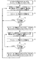
次に図16を参照すると、対になったベース・レジスタとマスク・レジスタとのセットを用いたスヌープ・フィルタに対する制御フローの詳細プロセス流れ図が示されている。作業の開始において、ステップ730に示されるように全ストリーム・レジスタ、全マスク及び全スヌープ・キュートはリセットされ、ステップ732に示されるように、システムはいずれかのスヌープ元からの次のスヌープ要求を待つ。新しいスヌープ要求が受信されると、ステップ734で示されるように、該スヌープ要求のアドレスはすべてのアドレス・ストリーム・レジスタ及びマスク(ストリーム・レジスタの両セット)と照合される。スヌープ要求のアドレスは、付随するマスクと組み合わされた全ストリーム・レジスタ(すなわち、全アドレス・ストリーム・レジスタとマスク(ストリーム・レジスタの両セット))と照合される。ステップ736での判断において、現下のスヌープ要求の照合が、対のマスク・レジスタと組み合わされたあるストリーム・レジスタと一致すると、当該スヌープ・キャッシュ・ラインがキャッシュの中にある可能性があり、スヌープ要求は、ステップ740において、スヌープ・キューに置かれてキャッシュに送られる。プロセスはステップ732に戻り次のスヌープ要求を待つ。しかしながら、スヌープ要求が、ストリーム・レジスタの両方のセット中の、対のマスクと組み合わされたいずれのストリーム・レジスタとも一致しない場合は、当該スヌープ・キャッシュ・ラインがキャッシュ中にないことが保証される。かくて、このスヌープ要求は、ステップ738でフィルタ除去され、プロセスは732に戻る。
Referring now to FIG. 16, a detailed process flow diagram of the control flow for a snoop filter using a paired base register and mask register set is shown. At the start of the work, all stream registers, all masks and all snoop cutes are reset as shown in
次に図17を参照すると、置換えられたキャッシュ・ラインに対し、2つのストリーム・レジスタ・セット、及びキャッシュ・ラップ検知ロジック・ブロックを更新するための制御フローが示されている。作業の開始において、ステップ750で示されるように、ストリーム・レジスタ及びマスクのすべてはリセットされ、キャッシュ・ラップ検知ロジックはクリアされて、レジスタの第一セットがアクチブにされる。プロセッサの、L1キャッシュの欠落に対するメモリ要求(ロード又は格納オペレーション要求のいずれも含む)の各々対し、該メモリ要求のアドレスがストリーム・レジスタの第一セットに加えられ、該セットをアクチブ・アドレス・ストリーム・レジスタ・セットと呼ぶ。レジスタの第一セットからのアドレス・ストリーム・レジスタのすべてがチェックされて、実装されているレジスタ選定基準の指定により最善に一致するものが選定される:又はこれに換えて、最初の空ストリーム・レジスタを選定してもよい。メモリ要求のアドレスは、ステップ752に示されるように、アクチブ・レジスタ・セット中の選定されたストリーム・アドレス・レジスタの中に格納され、対となるマスクは更新され、該アドレスのどのビットが関連しどのビットが関連しないのかを反映する。次いで、ステップ754において、キャッシュ・ラップ検知ロジックが更新され、キャッシュにロードされた新しいデータを反映する。キャッシュ・ラップ検知ブロックは、アクチブ・レジスタが最初に使用開始されて以来、キャッシュ中のラインすべてが置換えられたかどうかを追跡記録する。かくして、ステップ756において、キャッシュ・ラップさせる状態になっているかどうかが判断がされる。ステップ756においてキャッシュ・ラップ状態が検知されなければ、制御フローはステップ752にループ・バックし、システムは次のプロセッサ・メモリ要求を待つ。一方、キャッシュ・ラップ状態が検知された場合、制御はステップ758へと続き、キャッシュ・ラップ検知ロジック・ブロックはクリアされ、第二ストリーム・レジスタ及びマスク・セットがステップ758においてクリアされる。次のステップ760に進み、システムは次のプロセッサ・メモリ要求を待つ。新しいメモリ要求に対し、レジスタの第二セットの全アドレス・ストリーム・レジスタがチェックされ最善に一致するものが選定され、例えば、実装されたレジスタ選定基準に指定されたレジスタ、又は最初の空ストリーム・レジスタが選定される。メモリ要求のアドレスは、ステップ760に示されるように、第二レジスタ・セット中の選定されたストリーム・アドレス・レジスタのなかに格納され、対となるマスクは更新され、該アドレスのどのビットが関連しているかを反映する。ステップ762に進み、キャッシュ・ラップ検知ロジックは更新され、キャッシュにロードされた新規データを反映する。キャッシュ・ラップ検知ロジックは、レジスタの第二セットが開始されて以来、置換えられたキャッシュ中のラインすべてを追跡記録しており、これにより、ステップ764において、キャッシュ・ラップ状態が存在するかどうかを決める判断が行われる。ステップ764においてラップ・イベントが検知されなければ、システムは、ステップ760に戻り、次のプロセッサ・メモリ要求を待つ。一方、キャッシュ・ラップ・イベントが検知された場合は、レジスタ及びマスクの第一セットが再び使われることになる。かくして、ステップ766において、レジスタの第一セットのレジスタと対のマスクとのすべてがリセットされ、キャッシュ・ラップ検知ロジックはクリアされる。レジスタの第一セットは、再びキャッシュの内容を見積もるためのアクチブとして使われ、制御フローはステップ752にループ・バックされる。
Referring now to FIG. 17, there is shown a control flow for updating two stream register sets and cache wrap detection logic blocks for the replaced cache line. At the start of the work, as shown in
ストリーム・レジスタ・スヌープ・フィルタの使用について前に説明したように、ゼロにセットされたマスク・ビットの数が増えるにつれ、各ストリーム・レジスタ・フィルタのスヌープ要求を阻止する力は低減する。例えば、全マスク・ビットがゼロの場合、スヌープ要求はすべて通過してしまう。また一方、仮にこれらのマスク・ビットが一回に1ビットだけゼロにセットされるとすれば(すなわち、各ロードが1ビットだけストリーム・レジスタと異なる)、このような場合、丁度2ビットのストリーム・レジスタと異なるビットを持つアドレスに対するスヌープ要求は、たとえそのアドレスがキャッシュにある可能性がない場合でも通過させることになる。こうして、異なるビットの数など、さらに複雑又は微細な違いの検出を可能にするシグネチャ・フィルタを実装することによって、追加されたフィルタリング能力が具備される。一般的な考え方は、マスク・フィルタとシグネチャ・フィルタとの双方が、該アドレスがキャッシュにある可能性を示す場合に限って、スヌープをストリーム・レジスタから転送するというものである。 As previously described for the use of stream register snoop filters, as the number of mask bits set to zero increases, the ability to block each stream register filter snoop request decreases. For example, if all mask bits are zero, all snoop requests will pass. On the other hand, if these mask bits are set to zero one bit at a time (ie, each load is different from the stream register by one bit), then in this case just a 2-bit stream Snoop requests for addresses with different bits from the register will be passed even if the address is not likely to be in the cache. Thus, additional filtering capabilities are provided by implementing signature filters that allow detection of more complex or fine differences, such as the number of different bits. The general idea is that both the mask filter and the signature filter transfer snoops from the stream register only if they indicate that the address may be in the cache.
図18を参照すると、入力を取り入れるシグネチャ機能900、アドレス901、ストリーム・レジスタ902、及びストリーム・レジスタに関連する、アドレスのシグネチャ903の計算がある。下記のような、考えられる多くのシグネチャ機能がある。
1. アドレス中の、ストリーム・レジスタ・アドレスと異なるビットの数。
この数をsで表す。例えば、シグネチャをある定数Mに対するmin(M,s)に設定するなど、短縮係数を用いてスペースを節減することができる。
2. アドレスがNビットの場合、シグネチャは、あらゆるビットがゼロ値の長さB=(N+1)のベクトルである、但し、s=iの場合ビットiは1とする。スペースを節減するため、これを長さB+1(B+1<N)に切り詰めることができよう、min(s,B)=iの場合ビットiは1である。
3. アドレスをkヶ(k>1)のビット群に分割する。群iの長さはL(i)であり、M(i)=L(i)+1とする。s(i)を、群i中のストリーム・レジスタと異なる群i中のアドレス・ビットの数とする。このとき、シグネチャは、(s(1),s(2),…,s(k))で与えられ、これは単に各群の異なったビットの数である。これらの群については、互いに素なビットのセットにも、部分的にオーバーラップしているビットのセット(すなわち、アドレスの一部のビットが複数の群に在る)にも構成することができる。シグネチャの長さは、B(1)+…+B(k)であり、B(i)は、s(i)が取り得るあらゆる値を表すために必要なビットの数である。
4. 上記の(2)と(3)との組み合わせ。この組み合わせにおいて、シグネチャは、各々の群に対応するkビットのベクトルから成る。s(j)=iの場合、群j中のビットiは1にセットされる。群iがL(i)ビット長さの場合、s(i)が取り得るあらゆる値を符号化するためにはM(i)=(L(i)+1)のビットが必要となる。シグネチャはM(1)+…+M(k)ビットの長さとなる。例えば、ある定数Mに対して、min(M,s(j))=iとし群j中のビットiを1に設定するなどして、短縮係数を使いスペースを節減することができる。
5. 上記の(3)と同様であるが、s(1),…,s(k)の別の一意的な組み合わせとしてM(1)×…×M(k)がある。
6. アドレスをkヶ(k>1)のビット群に分割し、p(i)を、群i中のアドレス・ビットのパリティとする。このとき、シグネチャは、(p(1),p(2),…,p(k))で与えられる。
7. 上記の(6)と同様であるが、2kのパリティの組み合わせの各々を整数qに符号化し、長さ2kのゼロのビット・ベクトルを戻す、但しビットqは1とする。
この他に多くのシグネチャが可能なことは言うまでもない。
Referring to FIG. 18, there is a
1. The number of bits in the address that are different from the stream register address.
This number is represented by s. For example, the space can be saved by using a shortening factor, such as setting the signature to min (M, s) for a certain constant M.
2. If the address is N bits, the signature is a vector of length B = (N + 1) where every bit is zero, where bit i is 1 if s = i. To save space, the bit i is 1 when min (s, B) = i so that it can be truncated to length B + 1 (B + 1 <N).
3. The address is divided into k (k> 1) bit groups. The length of group i is L (i), and M (i) = L (i) +1. Let s (i) be the number of address bits in group i that are different from the stream registers in group i. At this time, the signature is given by (s (1), s (2),..., S (k)), which is simply the number of different bits in each group. These groups can be configured as disjoint sets of bits or partially overlapping sets of bits (ie, some bits of the address are in multiple groups). . The signature length is B (1) +... + B (k), where B (i) is the number of bits required to represent any possible value of s (i).
4). Combination of (2) and (3) above. In this combination, the signature consists of a k-bit vector corresponding to each group. If s (j) = i, bit i in group j is set to 1. When group i is L (i) bits long, M (i) = (L (i) +1) bits are required to encode any possible value of s (i). The signature is M (1) +... + M (k) bits long. For example, for a certain constant M, space can be saved by using a shortening coefficient by setting min (M, s (j)) = i and setting bit i in group j to 1.
5). Although it is the same as said (3), there exists M (1) * ... * M (k) as another unique combination of s (1), ..., s (k).
6). The address is divided into k (k> 1) bit groups, and p (i) is the parity of the address bits in group i. At this time, the signature is given by (p (1), p (2),..., P (k)).
7. Same as (6) above, but encodes each 2k parity combination into an integer q, returning a zero bit vector of length 2k, where bit q is 1.
Needless to say, many other signatures are possible.
アドレス901がキャッシュにロードされると、シグネチャ903が、シグネチャ更新機能904に供給される。また、更新機能は、入力としてシグネチャ・レジスタ905の前の値も取り込み、それを新しい値906で置換える。シグネチャ・レジスタを更新する適切な方法は、シグネチャの種類の如何による。S_oldはシグネチャ・レジスタの旧い値を表し、S_newがシグネチャ・レジスタの新しい値を表し、Vはシグネチャ903の値を表すものとする。上記のシグネチャ機能に対応して、シグネチャ更新機能904は、以下の項目を計算する。
1. S_new=max(S_old,V)。これは、ストリーム・レジスタと異なるビットの最大数を追跡記録する。
2. S_new=S_oldビット単位又は(bit−wide−or)V。これは、異なるビットのスコアボードを保持する。
3. S_new=max(S_old,V)。これは、各群中のストリーム・レジスタと異なるビットの最大数を追跡記録する。
4. S_new=S_oldビット単位又はV。これは、各群中の異なるビットのスコアボードを保持する。
5. S_new=S_oldビット単位又はV。これは、各群中の同時に生じた異なるビットのスコアボードを保持する。
6. S_new=S_oldビット単位又はV。これは各群中のパリティのスコアボードを保持する。
7. S_new=S_oldビット単位又はV。これは各群中の同時に生じたパリティのスコアボードを保持する。
When address 901 is loaded into the cache,
1. S_new = max (S_old, V). This keeps track of the maximum number of bits different from the stream register.
2. S_new = S_old bit unit or (bit-wide-or) V. This holds a different bit scoreboard.
3. S_new = max (S_old, V). This keeps track of the maximum number of bits different from the stream registers in each group.
4). S_new = S_old bit unit or V. This maintains a scoreboard for the different bits in each group.
5). S_new = S_old bit unit or V. This keeps scoreboards of different bits occurring simultaneously in each group.
6). S_new = S_old bit unit or V. This maintains a parity scoreboard in each group.
7. S_new = S_old bit unit or V. This keeps a scoreboard of simultaneously generated parities in each group.
スヌープ要求が着信すると、そのシグネチャが計算され、シグネチャ・レジスタと対比される。これが一致しなければ、そのアドレスがキャッシュの中に在ることはなく、通常のストリーム・レジスタ及びマスク・フィルタが要求がキャッシュの中にある可能性を示していたとしても、該要求はフィルタ除去される。スヌープは、シグネチャ・レジスタとマスク・レジスタとの双方ともが当該アドレスがキャッシュ中にある可能性を示した場合にだけ転送される。 When a snoop request arrives, its signature is calculated and compared with the signature register. If this does not match, the address will not be in the cache, and the request will be filtered out even if the normal stream register and mask filter indicate that the request may be in the cache. Is done. A snoop is transferred only if both the signature register and the mask register indicate that the address may be in the cache.
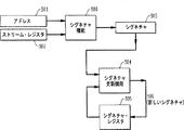
シグネチャ・フィルタリングのメカニズムが図19に示されている。キャッシュへのロード・アドレス1001は、マスク更新ロジック1002に送信され、該ロジックは、先に説明したように動作し、前のマスク・レジスタ1003、ストリーム・レジスタ1004を取り込み、該マスク・レジスタ1003を更新する。また、このアドレス1001はシグネチャ機能1005にも供給され、該機能も入力としてストリーム・レジスタ1004を取り込みシグネチャ1006を生成する。シグネチャ1006及び前のシグネチャ・レジスタ1008は、シグネチャ更新ロジック1007に供給され、該ロジックはシグネチャ・レジスタ1008に対する新規の値を生成する。
The signature filtering mechanism is shown in FIG. The
スヌープ・アドレス1009a要求が着信すると、マスク・フィルタ1010がこれを受信して処理し、マスク・スヌープ要求1011を生成する。さらに、この同じスヌープ・アドレス(1009bとして示す)及びストリーム・レジスタ1004が、シグネチャ機能1012に供給され、シグネチャ1013が生成される。なお、シグネチャ機能1005と1012とは同じロジックでなければならない、すなわち、これらは同一の入力を得た場合同一の出力を生成することになる。スヌープ要求1013のシグネチャとシグネチャ・レジスタがシグネチャ・フィルタ1014に供給される。
When a snoop
このフィルタは、このシグネチャを有する要求がキャッシュ中にある可能性があるかどうかを判定しなければならず、その作業の正確さはシグネチャの種類の如何による。シグネチャ更新機能が「スコアボード」型の場合、スヌープのシグネチャは、ビット単位でシグネチャ・レジスタとの論理積を取られる。この結果がゼロでない場合、スヌープ・シグネチャ要求1015が作成される(要求が作成される場合は、当該信号が1にセットされ、されない場合は0となる)。シグネチャ更新機能が「変更されたビットの最大数」型の場合、スヌープ・シグネチャがシグネチャ・レジスタ以下の数かどうかを点検するチェックが行われる(各群毎に一対比)。このような対比のすべてが真であれば、当該アドレスがキャッシュ中にある可能性があり、シグネチャ・スヌープ要求1015が作成される。マスク・スヌープ要求1011とシグネチャ・スヌープ要求1015とは、ロジック・エレメント1016において論理積が取られ、スヌープ要求信号1017が生成される。この信号が1の場合、スヌープ・ベクトル・リスト、又は適用レンジ・フィルタ(図7参照)によって排除されない限り、スヌープ要求が生成されることになる。但し、正確に言えば、このようなスヌープ要求を、別のストリーム・レジスタによるシグネチャマスク・フィルタの結果によって排除することはできない。
This filter must determine whether a request with this signature may be in the cache, and the accuracy of its work depends on the type of signature. If the signature update function is of the “scoreboard” type, the snoop signature is ANDed with the signature register bit by bit. If this result is non-zero, a snoop
シグネチャ・レジスタは、ストリーム・レジスタが最初にセット又はリセットされるのと同時に適切にセットされる。スコアボード型及び最大型のシグネチャ対しては、シグネチャ・レジスタはすべてゼロにセットされる(ストリーム・レジスタとビット差異がないことを示す)。 The signature register is set appropriately at the same time that the stream register is initially set or reset. For scoreboard type and maximum type signatures, the signature registers are all set to zero (indicating no bit difference from the stream registers).
ストリーム・レジスタは、特定の開始状態に関連して、キャッシュの全体内容をどの時点で置換えるか−本明細書ではこれをキャッシュ・ラップ状態という−の認知に依存している。セットアソシアティブ・キャッシュは、キャッシュ内のセットのすべてが置換えられたとき、ラップしたと見なされる。通常、一部のセットは、他のものよりも早く置換えられ、セットすべてが置換えられキャッシュがラップする前に、更新状態を継続する。従って、キャッシュ・ラップ検知の開始点は、前回のキャッシュ・ラップ時のキャッシュ・セットの状態である。 The stream register relies on the perception of when to replace the entire contents of the cache, which is referred to herein as a cache wrap condition, in relation to a particular starting state. A set associative cache is considered wrapped when all of the sets in the cache have been replaced. Typically, some sets are replaced earlier than others, and the update state continues before all sets are replaced and the cache wraps. Therefore, the starting point of the cache wrap detection is the state of the cache set at the previous cache wrap.
一つの実施形態において、キャッシュはセットアソシアティブであり、ラウンドロビン置換えアルゴリズムを用いているが、他の置換え法実施も可能である。例えば、キャッシュが、最近最少使用置換及びランダム置換を含む、任意置換方式を実行している場合、キャッシュ・ラップ検知を活用することができる。以下に述べるように、セットアソシアティブ(SA)キャッシュは、いくつかの数のセットを含み、各セットは、複数のライン(各々が同一のセット・インデックスを持つ)を格納することができる。セット内のラインは「ウェイ」と呼ばれる。従って、2ウェイ・セットアソシアティブキャッシュは、セットあたり2本のラインを有する。セット内のウェイは、すべてルックアップ時に同時に探索でき、更新時にはその一つだけが置換えられる。さらに、ウェイのサブセット各々のパーティションに割り当てられるように、セットを区分けすることができる。例えば、4ウェイSAキャッシュを2つの2ウェイSAキャッシュに区分けすることができる。仮想メモリ・ページ・テーブル(及び変換索引バッファ(TLB))は、特定のメモリ参照がどのパーティションを対象とするのかを(検索及び更新の双方に対し)特定するパーティション識別子を提供することができる。キャッシュ・ラップで更新されるウェイを格納するレジスタは、ウェイ番号を格納するのに十分な大きさが必要である。例えば、4ウェイSAキャッシュに対しては2ビット、又は32ウェイSAキャッシュに対しては5ビットである。各セットが異なった時期にラップできるように、セット毎にこのようなレジスタが一つある。 In one embodiment, the cache is set associative and uses a round robin replacement algorithm, but other replacement implementations are possible. For example, cache wrap detection can be exploited if the cache has recently performed an arbitrary replacement scheme, including least used replacement and random replacement. As described below, a set associative (SA) cache includes a number of sets, each set capable of storing multiple lines, each having the same set index. The lines in the set are called “ways”. Thus, a 2-way set associative cache has two lines per set. All ways in the set can be searched simultaneously at lookup time and only one of them is replaced at update time. In addition, the set can be partitioned so that it is assigned to a partition for each subset of ways. For example, a 4-way SA cache can be partitioned into two 2-way SA caches. The virtual memory page table (and translation index buffer (TLB)) can provide a partition identifier that identifies (for both retrieval and update) which partition a particular memory reference is intended for. The register storing the way updated by the cache wrap needs to be large enough to store the way number. For example, 2 bits for a 4-way SA cache or 5 bits for a 32-way SA cache. There is one such register per set so that each set can wrap at different times.
本発明の一つの実施形態において、キャッシュは3つのパーティションに区分可能であり、各パーティションは、キャッシュ・ウェイの連続するサブセットを含み、これらサブセットは各キャッシュ・セット内では同様である。メモリ参照は、3つのパーティションのいずれかの中にキャッシュ格納される、プロセッサのメモリ管理ユニットにより指定される。あるパーティションに対する更新は、他のパーティションとは関係なく行われ、一つのパーティションが全体のキャッシュ・ラップのずっと前にラップすることができる。しかしながら、パーティションが何時更新されるかが分かれば、パーティションのラッピングを検知するのと、キャッシュ全体のラッピングを検知するのとは同じことである。しかして、以降に述べるように、キャッシュ・ラッッピングは、パーティション・ラッピングもキャッシュ全体ラッピングも含む。 In one embodiment of the invention, the cache can be partitioned into three partitions, each partition containing a contiguous subset of cache ways, which are similar within each cache set. The memory reference is specified by the memory management unit of the processor, which is cached in any of the three partitions. Updates to one partition are done independently of other partitions, and one partition can wrap long before the entire cache wrap. However, if you know when a partition is updated, detecting partition wrapping is the same as detecting entire cache wrapping. Thus, as will be described later, cache wrapping includes both partition wrapping and whole cache wrapping.
外部のロジックがキャッシュ更新を検知するためには、キャッシュが更新が発生していること、及びどのラインが上書きされるのかの表示を提示しなければならない。該好適な実施形態のロジックは、この情報がセット仕様、ウェイ仕様、及び更新インジケータを使って提示されることを前提としている。 In order for external logic to detect a cache update, it must present an indication that the cache is being updated and which lines are being overwritten. The logic of the preferred embodiment assumes that this information is presented using set specifications, way specifications, and update indicators.
図20(a)及び(b)は、Nウェイ・セットアソシアテイブ・キャッシュの好適な実施形態によるキャッシュ・ラップ検知ロジックを示す。この実施形態では、セットの更新は必ずラウンドロビン順序で実施されることが前提となっている。すなわち、選択された「犠牲」ウェイが、前回上書きされたウェイに続いて上書きされる。 20 (a) and 20 (b) illustrate cache wrap detection logic according to a preferred embodiment of an N-way set associative cache. In this embodiment, it is assumed that the set update is always performed in a round robin order. That is, the selected “sacrificial” way is overwritten following the previously overwritten way.
図20(a)は、ロジック・ブロック920内に、単一のセット(示された実施形態ではセット「i」)の単一のパーティションのラップを検知するため実装されたロジックの一つ実施形態を示す。このロジックがセットi中にラップを検知した場合、該ロジックはset_wrap(i)信号910をアサートする。図20(b)は、キャッシュの全Nヶセットからの個々のset_wrap(i)信号910を、OR論理関数を使って、どのように組合せて、cash_wrap912を生成するかを示しており、信号912は、キャッシュ全体が(すなわち全セット)がラップ完了するとアサートする。なお、図20(a)及び(b)に示されているロジック及び回路は単なる一つの実施例であり、当業者は、本発明の範囲から逸脱することなくこれに多くの変形及び変更を加えることができることを認識するであろう。
FIG. 20 (a) illustrates one embodiment of logic implemented within
図20(a)の左側に、ラッピングのためモニタされているパーティションがキャッシュ更新対象に入る時期を判断する、パーティション検知ロジック・ブロック922が示されている。このロジックは、「下部」916で特定されるウェイと「上部」918で特定されるウェイとの間にあるパーティションを担当している。従って、セット・ラップ・パーティションを検知するロジックは、更新が行われ当該パーティションが更新対象となるときにだけその状態を変える。なお、パーティション検知ロジック922は、セット・ラップ検知ロジックのNヶすべてのコピーに共通のものである。
On the left side of FIG. 20 (a), a partition
セット・ラップ検知ロジック内の、共通パーティション更新インジケータは、更新が当該ロジックに関連する特定のセットiに対するものである場合にだけ作動するようさらに条件付けされている。これは、セット指定子924を、セット・ラップ検知ロジック926のインデックスと対比することによって実施される。
Within the set wrap detection logic, the common partition update indicator is further conditioned to operate only if the update is for a specific set i associated with that logic. This is accomplished by comparing the set specifier 924 with the index of the set
ロジック回路は次のように機能する。始めに、flip−flop driving set_wap(i)930はクリアされセットがラップしていないことを示しており、レジスタ928は、更新してセット・ラップを完了しなければならないウェイを含むと仮定する。この状態で該レジスタはその値を保持する。キャッシュ更新が発生すると、ウェイ914は、コンパレータ・デバイス919にレジスタ928の内容と対比、判断され、flip−flop driving set_wap(i)930にロジック1がロードされて、これによりset_wap(i)910がアサートする。その後、キャッシュの更新により更新されたウェイ914がレジスタ928中に格納され、レジスタ928は効果的にこれらの更新を追跡する。キャッシュ・セットのすべてがラップすると、図20(b)に示されるように、組み合わされたcash_wrap912信号がアサートされ、これによりflip−flop driving set_wap(i)930はクリアされる(RestがLoadより優先すると仮定する)。これにより、回路は初期の状態に戻り、レジスタ928は更新が必要なウェイを格納し、次のセット・ラップを表示する。
The logic circuit functions as follows. Initially, flip-flop driving set_wap (i) 930 is cleared to indicate that the set has not wrapped, and assume that
しかして、セット毎に一つのレジスタがあり、該レジスタはあるウェイの番号とそのウェイが上書きされ次いでセットがラップされる時期を格納していることが理解される。しかしながら、各セットは異なる時期にラップ(アクセス・パターン如何による)するので、すべてのセットがラップするまではキャッシュ全体がラップしたとは見なされない。この全体ラップ時点で、犠牲ウェイのポインタ(すなわち最後に上書きされたウェイに対するポインタ)の状態は、次のキャッシュ・ラップを検知するため初期状態となる。この第一実施形態は、それ自体がラップした時とキャッシュ全体がラップした時との間に上書きされたウェイの追跡記録をする上記のレジスタを具えることによってこの必要条件を満たしている。キャッシュ全体がラップすると、該実施形態は上書きされたウェイの追跡を止め、セットが次にラップする時期を判断する比較のためのベース状態となる。 Thus, it will be appreciated that there is one register per set, which stores the number of a way and when that way is overwritten and then the set is wrapped. However, since each set wraps at different times (depending on the access pattern), the entire cache is not considered wrapped until all sets wrap. At the time of this entire wrap, the state of the victim way pointer (ie, the pointer to the way that was overwritten last) becomes the initial state in order to detect the next cache wrap. This first embodiment meets this requirement by including the above register that keeps track of the way that was overwritten between when it wraps itself and when the entire cache wraps. When the entire cache wraps, the embodiment stops tracking overwritten ways and is the base state for comparison to determine when the set wraps next.
キャッシュ・ラップ検出ロジックの第二の実施形態においては、カウンタが実装され、キャッシュ全体がラップすると、すべてのセット・カウンタがパーティションの中のウェイの数にリセットされる。ウェイが上書きされるにつれ、カウンタは、カウント・ダウンされ、カウンタがゼロになると対応セットがラップされる。全カウンタがゼロに達すると、当該キャッシュがラップしたことになり、プロセスが再び開始される。 In the second embodiment of the cache wrap detection logic, counters are implemented and when the entire cache wraps, all set counters are reset to the number of ways in the partition. As the way is overwritten, the counter is counted down and the corresponding set is wrapped when the counter reaches zero. When all counters reach zero, the cache has wrapped and the process begins again.
この第二実施形態によれば、図20(a)に示されたボックス920内に具えられたラップ済みセット検知ロジックは、レジスタ及びコンパレータではなく、ロード可能なカウンタに基づいている。このロジックは図21に示されている。このロジックでは、ダウンカウンタ・デバイス932には、パーティション936中のウェイの数がロードされており、set_wrap(i)910がアサートされている(LoadはDownに優先すると仮定する)。全セットがラップし、cash_wrap912がアサートされると、flip−flop driving set_wap(i)930はクリアされ、カウンタ932のロードはなくなる。その後、ロジックが、パーティション914及びセット934の各々の更新を追跡し、その都度カウンタ932が1つカウント・ダウンされる。これが0に達するとflip−flop driving set_wap(i)930には論理1がロードされ、これによりset_wrap(i)910がアサートされ、ロジックは初期状態に戻る。
According to this second embodiment, the wrapped set detection logic provided in the
図22に示された、キャッシュ・ラップ検知ロジックの第三の実施形態は、最近最少使用法及びランダム法を含め、どのような置換え基準を実行するキャッシュに対しても機能する。このケースでは、スコアボード940を使って、上書きされる正確なキャッシュ・ウェイ914が追跡記録される。具体的には、これを使って、一切のウェイに対する最初の書き込みが検知される。さらに、カウンタ942は、スコアボード・ビットが最初にセットされた(すなわち、0から1へのセット)回数を追跡記録する。該カウンタは、単に、上書きされたビット(旧いビット)がゼロのスコアボード書き込みをカウントすることによってこれを行う。カウンタ942には、パーティション・サイズ936(すなわち、当該パーティションの中のウェイの数)がプリロードされ、このカウンタが0に達すると、全部のキャッシュ・パーティションがラップしたことになる。これは、cash_wrap912信号のアサートによって示され、これにより、カウンタ942は再ロードされ(LoadはDownに優先すると仮定する)、スコアボード940はクリア(リセット)される。
The third embodiment of the cache wrap detection logic shown in FIG. 22 works for caches that perform any replacement criteria, including recently least-used and random methods. In this case, the
本発明の好適な実施形態は、ライトスルー・キャッシュと併せて実施され、書き込み要求に対してだけスヌーピングが行われてスヌープ処置の結果はローカル・データ・コピーを無効にすることであるが、本発明は前記に限定されない。例えば、ライトバック・キャッシュ編成と併用して本発明を実施できる。ライトバック・キャッシュによる場合は、コヒーレンス・プロトコルは、例えば、以下に限定はされないが、周知のMESIプロトコル、又は他のコヒーレンス・プロトコルを含め、追加のトランザクションを包含することになる。ライトバック・キャッシュのコヒーレンス・プロトコルによれば、遠隔プロセッサへの書き込みトランザクションでは、スヌープ処置が実施され、遠隔キャッシュが主メモリに関する最新のコンピュータを有しているかどうかが判断される。この場合、以下に限定はされないが、最新のデータを有するプロセッサに該データを主メモリに書き込ませる方法、最新コピー所有のプロセッサから要求元に直接データを転送する方法、又は、他の任意の特定プロトコルのスヌープ介入によるデータ伝送方法を含め、いくつかのやり方の一つを使ってデータ転送を実施する。本発明によれば、スヌープ・フィルタリング処置を用いてより速くスヌープ対応を決定することができる。 The preferred embodiment of the present invention is implemented in conjunction with a write-through cache, where snooping is done only for write requests and the result of the snoop action is to invalidate the local data copy. The invention is not limited to the above. For example, the present invention can be implemented in combination with write-back cache organization. In the case of a write-back cache, the coherence protocol will include additional transactions, including, but not limited to, the well-known MESI protocol, or other coherence protocols. According to the write-back cache coherence protocol, in a write transaction to a remote processor, a snoop procedure is performed to determine whether the remote cache has an up-to-date computer for main memory. In this case, but not limited to the following, a method of causing the processor having the latest data to write the data to main memory, a method of transferring the data directly from the processor having the latest copy to the requestor, or any other specific Data transfer is implemented using one of several methods, including data transmission methods with protocol snoop intervention. According to the present invention, a snoop response can be determined more quickly using a snoop filtering procedure.
これら好適な実施形態を、固定的な相互接続形態、及び固定的なスヌープ・フィルタリング・オペレーションに関連させて説明してきたが、本発明の一つの態様において、スヌープ・フィルタリング・システムは、一つ又はそれより多くのレベルのスヌープ・フィルタ階層においてプログラムが可能な特質を有する。本発明のプログラム可能な特質面の一つの実施形態によれば、相互接続形態が選択される。プログラム可能な接続形態の一つの実施例によれば、接続形態に関し、各種フィルタの間で1対1関係及び1対多関係を選択できる。プログラム可能な実施形態の別の態様によれば、第一スヌープ・フィルタの次に第二スヌープ・フィルタにアクセスする、又はこれに換えて、第一及び第二スヌープ・フィルタに並行してアクセスする順番をプログラム制御により設定することができる。 Although these preferred embodiments have been described in the context of a fixed interconnect configuration and a fixed snoop filtering operation, in one aspect of the invention, the snoop filtering system can be one or It has programmable characteristics in a higher level of snoop filter hierarchy. According to one embodiment of the programmable feature of the present invention, an interconnect configuration is selected. According to one embodiment of the programmable topology, one-to-one and one-to-many relationships can be selected between the various filters for the topology. According to another aspect of the programmable embodiment, the first snoop filter is accessed next to the second snoop filter, or alternatively, the first and second snoop filters are accessed in parallel. The order can be set by program control.
本発明のプログラム可能な特質面のさらに別の実施形態のさらに別の態様によれば、フィルタのサブユニットの動作のプログラムが可能である。これは、例えば、スヌープされるキャッシュの結合性、実装されるコヒーレンス・アーキテクチャなどといったプログラム可能な特性の設定を行うことによって、スヌープ・フィルタの構成が可能な態様の形で実施することができる。プログラム可能なフィルタ・サブユニットの別の態様において、フィルタ・サブユニットはプログラム可能なマイクロコードとして実施され、これにより、プログラム可能なエンジンが、命令のシーケンスを実行して本明細書に記載した一つ以上の好適な実施形態の機能を実行する。一つの態様では、これは汎用マイクロコード・エンジンである。別の態様において、これは、用途最適化されたプログラム可能マイクロコード・エンジンであり、該プログラム可能マイクロコード・エンジンは、スヌープ・フィルタ固有の状態を検知するための専用対応ロジック、ならびに随意により、「キャッシュ・ラップ条件分岐」及び、例えば、「キャッシュ・ラップ条件による割り込み」のようなマイクロコード・エンジンに配信されるマイクロコード・エンジン固有の例外通知の形による専用の通知イベントなどの専用のオペレーションを有する。 According to yet another aspect of yet another embodiment of the programmable feature of the present invention, the operation of the filter subunits is programmable. This can be implemented in a manner that allows the configuration of a snoop filter, for example, by setting programmable characteristics such as the snooping cache connectivity, the implemented coherence architecture, etc. In another aspect of the programmable filter subunit, the filter subunit is implemented as programmable microcode, which allows the programmable engine to execute a sequence of instructions as described herein. Perform the functions of one or more preferred embodiments. In one embodiment, this is a general purpose microcode engine. In another aspect, this is an application-optimized programmable microcode engine that includes dedicated corresponding logic for detecting a snoop filter specific condition, and optionally, Dedicated operations such as "cache wrap condition branch" and dedicated notification events in the form of microcode engine specific exception notifications delivered to the microcode engine, eg "interrupt due to cache wrap condition" Have
本発明のプログラム可能な特質面のさらに別の実施形態において、スヌープ・フィルタリング態様の一部又は全部は、プログラム可能スイッチ・マトリックス、又はプログラム可能ゲート・アレイ・ファブリックを組み込んで実施される。これらの態様の一つにおいて、スヌープ・サブユニット間の経路指定は、プログラム可能スイッチ・マトリックスを設定することによって行われる。このプログラム可能な実施形態の別の態様では、スヌープ・フィルタ・ユニットの動作は、プログラム可能ゲート・アレイ・ロジック・ブロックを設定することによって実施される。本発明の別の態様において、スヌープ・フィルタ・ブロック全体が、少なくとも一つのフィールド・プログラマブル・ゲート・アレイ・セルを設定することによって実施される。 In yet another embodiment of the programmable feature of the present invention, some or all of the snoop filtering aspects are implemented incorporating a programmable switch matrix or programmable gate array fabric. In one of these aspects, routing between snoop subunits is done by setting a programmable switch matrix. In another aspect of this programmable embodiment, the operation of the snoop filter unit is implemented by setting a programmable gate array logic block. In another aspect of the invention, the entire snoop filter block is implemented by setting at least one field programmable gate array cell.
本発明のプログラム可能な特質面の別の実施形態によれば、一つ以上のスヌープ・フィルタ・サブシステムを無効化することができ、特定のスヌープ・フィルタリング・ステップをバイパスすることができ、又は、スヌープ・フィルタリングを完全に無効化することができる。一つの実施形態において、これは、コンフィギュレーション・レジスタの中にスヌープ・フィルタの構成を書き込むことによって達成される。別の実施形態では、入力信号によってこの構成を選択することができる。 According to another embodiment of the programmable feature of the present invention, one or more snoop filter subsystems can be disabled, certain snoop filtering steps can be bypassed, or Snoop filtering can be completely disabled. In one embodiment, this is accomplished by writing the snoop filter configuration into the configuration register. In another embodiment, this configuration can be selected by an input signal.
本発明の好適な実施形態と考えられるものを提示し説明してきたが、当然ながら、本発明の精神から逸脱することなく、形態又は細部についてさまざまな変形及び変更を容易に行えることが理解されよう。従って、本発明は、説明され図示されたとおりの形態に限定されるものでなく、添付の請求範囲内に入るあらゆる変形が含まれると解釈すべきものとして意図されている。 While what has been considered as preferred embodiments of the invention has been presented and described, it will be appreciated that various changes and modifications can be readily made in form or detail without departing from the spirit of the invention. . Accordingly, the invention is not intended to be limited to the form as described and illustrated, but is to be construed as including all modifications that fall within the scope of the appended claims.
200a L1キャッシュ1
200b L1キャッシュ2
200n L1キャッシュN
250 システム・ローカル・バス
260 2点間相互接続
240a〜240n スヌープ・フィルタ
230 主メモリ
200b
200n L1 cache N
250 system
Claims (27)
前記スヌープ・フィルタは、
関連するプロセッシング・ユニットのキャッシュ・メモリ・レベル中にロードされたデータのキャッシュ・ライン・アドレスを追跡するようになされた第一メモリ格納手段であって、前記第一メモリ格納手段は、第一の複数ストリーム・レジスタ・セットを含み、各ストリーム・レジスタ・セットは、1つ又は複数のストリーム・レジスタを含み、各ストリーム・レジスタは、ベース・レジスタおよび対応するマスク・レジスタを含み、前記ベース・レジスタは、前記ストリーム・レジスタによって表される前記キャッシュ・ライン・アドレスすべてに共通するアドレス・ビットを追跡し、前記対応するマスク・レジスタは、これに対応するベース・レジスタに含まれる前に記録されたアドレスとの違いを表すビットを追跡し、当該違いを表すビットの位置は前記ベース・レジスタの対応するビットが判断外であることを示すように前記マスク・レジスタにおいて示される、前記第一メモリ格納手段と、
一つ以上のメモリ書き込み元からのスヌープ要求を受信する手段と、
受信したスヌープ要求のアドレスを、前記第一メモリ格納手段の前記複数のストリーム・レジスタ・セットに格納されたアドレス群と対比するためのスヌープ・チェック・ロジック手段と、
前記複数のストリーム・レジスタ・セットに格納されたアドレスとの一致を受けて、前記受信したスヌープ要求を前記プロセッシング・ユニットに転送し、又は、一致しない場合は前記スヌープ要求を廃棄するための手段と
を含む、前記スヌープ・フィルタ。A snoop filter associated with each processing unit of a computing environment having a plurality of processing units, wherein one processing unit of each of the plurality of processing units corresponds to one processing unit. one of which is associated with the snoop filter, each one of the processing units of said plurality of processing units includes one or more cache memory associated with said one processing unit,
The snoop filter is
First memory storage means adapted to track a cache line address of data loaded during a cache memory level of an associated processing unit, the first memory storage means comprising: A plurality of stream register sets, each stream register set including one or more stream registers, each stream register including a base register and a corresponding mask register, said base register Tracks the address bits common to all of the cache line addresses represented by the stream register, and the corresponding mask register was recorded before being included in the corresponding base register track bits representing the difference between the address table the difference Position of the bit is indicated in the mask register to indicate that the corresponding bit of the base register is out of decision, said first memory storage means,
Means for receiving a snoop request from one or more memory writers;
Snoop check logic means for comparing the address of the received snoop request with a group of addresses stored in the plurality of stream register sets of the first memory storage means;
Means for transferring the received snoop request to the processing unit in response to a match with an address stored in the plurality of stream register sets, or for discarding the snoop request if there is no match; The snoop filter.
複数のポート・スヌープ・フィルタと連通し、スヌープ要求のサブセットを受信し、エンキューし、そして、該スヌープ・フィルタの前記関連するプロセッシング・ユニットに転送する複数のプロセッサ・スヌープ・フィルタ・キュー手段
をさらに含む、請求項1に記載のスヌープ・フィルタ。Each of the snoop filters communicates with a plurality of port snoop filters, receives a plurality of snoop requests, enqueues, and forwards to the associated processing unit of the snoop filters, a plurality of processor snoop filters The snoop filter of claim 1, further comprising filter queue means.
前記スヌープ・フィルタ・キュー手段間をすべて調停し、前記複数のプロセッサ・スヌープ・フィルタ・キュー手段の各々から送られるすべてのスヌープ要求を逐次化し、前記関連するプロセッシング・ユニットに転送する手段
をさらに含む、請求項4に記載のスヌープ・フィルタ。Each of the snoop filters arbitrates between the snoop filter queue means, serializes all snoop requests sent from each of the plurality of processor snoop filter queue means, and sends them to the associated processing unit. The snoop filter of claim 4, further comprising means for forwarding.
前記更新するための手段は、レジスタ選定基準に基づきどのストリーム・ベース・レジスタ及びマスク・レジスタのセットを更新するかを判定するための手段を含む、請求項1に記載のスヌープ・フィルタ。Means for updating for each cache load performed with a cache line address of said first memory storage means;
The snoop filter of claim 1, wherein the means for updating includes means for determining which set of stream base and mask registers to update based on register selection criteria.
キャッシュ・ライン内のオフセットに対応する低位のビットを除去することによって、受信したスヌープ・アドレスをスヌープ・ライン・アドレスに変換するための手段と、
ベース・レジスタの内容を、対応するマスク・レジスタの内容と組み合わせた前記スヌープ・ライン・アドレスと対比し、当該特定のキャッシュ・ライン・アドレスにおける前記キャッシュ・メモリ・レベル中にデータが所在する可能性を示す結果信号を得るロジックを実行するための第一手段と
を含む、請求項1に記載のスヌープ・フィルタ。The snoop check logic means
Means for converting the received snoop address to a snoop line address by removing the low order bits corresponding to the offset in the cache line;
Contrast the contents of the base register with the snoop line address combined with the contents of the corresponding mask register, and the possibility of data being located in the cache memory level at that particular cache line address A snoop filter according to claim 1, comprising first means for executing logic to obtain a result signal indicative of
前記複数のポート・スヌープ・フィルタの各々がスヌープ・チェック・ロジック手段を実行して、それぞれの前記専用書き込み元から受信したスヌープ要求をフィルタリングし、同時にそれら要求のサブセットをその関連するプロセッシング・ユニットに転送する、請求項12に記載のスヌープ・フィルタ。The snoop filter further includes a plurality of port snoop filters operating in parallel with the plurality of dedicated input ports,
Each of the plurality of port snoop filters performs snoop check logic means to filter snoop requests received from the respective dedicated writer and at the same time a subset of those requests to its associated processing unit. 13. A snoop filter according to claim 12 for forwarding.
前記複数の専用入力ポートと連通し並列に動作する複数のキュー・デバイスであって、前記複数のキュー・デバイスの各々はそれぞれの専用メモリ書き込み元から受信した受信スヌープ要求をエンキューする、キュー・デバイスと、
前記エンキューされたスヌープ要求を前記スヌープ・チェック・ロジック手段に転送する調停多重化手段と
をさらに含む、請求項12に記載のスヌープ・フィルタ。The snoop filter is
A plurality of queue devices communicating with the plurality of dedicated input ports and operating in parallel, each of the plurality of queue devices enqueuing a received snoop request received from a respective dedicated memory writer When,
The snoop filter according to claim 12, further comprising: arbitration multiplexing means for forwarding the enqueued snoop request to the snoop check logic means.
前記スヌープ・チェック・ロジック手段は、前記受信スヌープ要求の前記アドレスを前記第二の複数ストリーム・レジスタ・セット中に格納されたアドレス群と対比する手段を含む、
請求項6に記載のスヌープ・フィルタ。A second multi-stream register symmetric to the first multi-stream register set for tracking a cache line address of data loaded into cache memory by the means for updating Further comprising second memory storage means having a set;
The snoop check logic means includes means for comparing the address of the received snoop request with an address group stored in the second multi-stream register set;
The snoop filter according to claim 6.
前記第一の複数ストリーム・レジスタ・セットの更新が再実施される、
請求項17に記載のスヌープ・フィルタ。Means for resetting the first multi-stream register set when a cache wrap detection condition is detected for a cache memory line tracked by the second multi-stream register set; Including
The first multi-stream register set update is re-executed;
The snoop filter according to claim 17.
全キャッシュ・ラインが置換えられたことを示すキャッシュ・ラップ状態の検出を受けて、前記第二の複数ストリーム・レジスタ・セットを前記第一の複数ストリーム・レジスタ・セットの内容に置き換えるための手段であって、前記スヌープ・チェック・ロジック手段は、前記受信したスヌープ要求の前記アドレスを、前記第二の複数ストリーム・レジスタ・セットとさらに対比する、前記置き換えるための手段と
をさらに含む、請求項1に記載のスヌープ・フィルタ。Second memory storage means having a second multi-stream register set corresponding to the first multi-stream register set;
Means for replacing the second multi-stream register set with the contents of the first multi-stream register set upon detection of a cache wrap condition indicating that all cache lines have been replaced; The snoop check logic means further comprises means for replacing the address of the received snoop request with the second multiple stream register set for further comparison. Snoop filter described in
前記キャッシュ・ラップ検出手段は、前記キャッシュの前記一つ以上の区分化サブセットそれぞれのあらゆるキャッシュ・ラインが、前の各キャッシュ・ラップ検知状態から置き換えられているかどうかを追跡する、
請求項15に記載のスヌープ・フィルタ。The first memory storage means is adapted to track a cache line address of data loaded during a cache memory level of an associated processing unit, and corresponding one or more sections of the cache One or more first multi-stream register sets having content relating to a generalized subset;
The cache wrap detection means tracks whether every cache line of each of the one or more partitioned subsets of the cache has been replaced from each previous cache wrap detection state;
The snoop filter according to claim 15.
キャッシュ・ラップ状態の検出に先だって、前記第一の複数ストリーム・レジスタ・セットの内容を前記一つ以上の第二の複数ストリーム・レジスタ・セットの各々にコピーするための手段であって、前記第一の複数ストリーム・レジスタ・セットの内容は、より高い頻度で更新されリセットされる、前記コピーするための手段と
をさらに含む、請求項21に記載のスヌープ・フィルタ。One or more second memory storage means each operating as said second multi-stream register set;
Means for copying the contents of the first multi-stream register set to each of the one or more second multi-stream register sets prior to detecting a cache wrap condition; The snoop filter of claim 21, further comprising: means for copying, wherein the contents of one multi-stream register set are updated and reset more frequently.
前記方法は、
プロセッシング・ユニット中の各スヌープ・フィルタに対し、
関連するプロセッシング・ユニットのキャッシュ・メモリ・レベル中にロードされたデータのキャッシュ・ラインのアドレスを追跡し、キャッシュ・ライン・アドレスを第一メモリ格納手段中に格納するステップであって、前記第一メモリ格納手段は、第一の複数ストリーム・レジスタ・セットを含み、各ストリーム・レジスタ・セットは、1つ又は複数のストリーム・レジスタを含み、各ストリーム・レジスタは、ベース・レジスタおよび対応するマスク・レジスタを含み、前記ベース・レジスタは、前記ストリーム・レジスタによって表される前記キャッシュ・ライン・アドレスすべてに共通するアドレス・ビットを追跡し、前記対応するマスク・レジスタは、これに対応するベース・レジスタに含まれる前に記録されたアドレスとの違いを表すビットを追跡し、当該違いを表すビットの位置は前記ベース・レジスタの対応するビットが判断外であることを示すように前記マスク・レジスタにおいて示される、前記格納するステップと、
一つ以上のメモリ書き込み元からスヌープ要求を受信するステップと、
受信したスヌープ要求のアドレスを、前記第一メモリ格納手段の前記複数のストリーム・レジスタ・セットに格納されたアドレス群と対比するステップと、
前記複数のストリーム・レジスタ・セットに格納されたアドレスとの一致を受けて、前記受信したスヌープ要求を前記プロセッシング・ユニットに転送し、又は一致しない場合は前記スヌープ要求を廃棄するステップと
を含む、前記方法。A snoop filtering method for supporting cache coherency in a computing environment having multiple processing units, each one of the processing units of said plurality of processing units corresponding to the one processing unit is associated with one of the snoop filter, each one of the processing units of said plurality of processing units includes one or more cache memory associated with said one processing unit,
The method
For each snoop filter in the processing unit,
Tracking the cache line address of data loaded during the cache memory level of the associated processing unit and storing the cache line address in a first memory storage means, The memory storage means includes a first multiple stream register set, each stream register set includes one or more stream registers, each stream register including a base register and a corresponding mask register. The base register tracks address bits common to all of the cache line addresses represented by the stream register, and the corresponding mask register corresponds to the corresponding base register Is different from the address recorded before Track bits representing the position of the bits representing the difference is shown in the mask register to indicate that the corresponding bit of the base register is out of decision, and said step of storing,
Receiving a snoop request from one or more memory writers;
Comparing the address of the received snoop request with a group of addresses stored in the plurality of stream register sets of the first memory storage means;
Receiving a match with an address stored in the plurality of stream register sets, forwarding the received snoop request to the processing unit, or discarding the snoop request if not matched. Said method.
前記受信したスヌープ要求を転送するステップは、
前記スヌープ・フィルタの前記関連するプロセッシング・ユニットに転送予定のスヌープ要求のサブセットを、ポート・スヌープ・フィルタに対応するそれぞれのプロセッサ・スヌープ・フィルタ・キュー手段中にエンキューするステップ
を含む、請求項23又は24に記載の方法。Each of the snoop filters includes a plurality of port snoop filters in communication with each of the memory write sources,
Forwarding the received snoop request;
24. Enqueuing a subset of snoop requests to be forwarded to the associated processing unit of the snoop filter into respective processor snoop filter queue means corresponding to a port snoop filter. Or the method according to 24.
Applications Claiming Priority (3)
| Application Number | Priority Date | Filing Date | Title |
|---|---|---|---|
| US11/093,130 US7392351B2 (en) | 2005-03-29 | 2005-03-29 | Method and apparatus for filtering snoop requests using stream registers |
| US11/093,130 | 2005-03-29 | ||
| PCT/US2006/010038 WO2006104747A2 (en) | 2005-03-29 | 2006-03-17 | Method and apparatus for filtering snoop requests using stream registers |
Publications (3)
| Publication Number | Publication Date |
|---|---|
| JP2008535093A JP2008535093A (en) | 2008-08-28 |
| JP2008535093A5 JP2008535093A5 (en) | 2012-05-10 |
| JP5120850B2 true JP5120850B2 (en) | 2013-01-16 |
Family
ID=37053890
Family Applications (1)
| Application Number | Title | Priority Date | Filing Date |
|---|---|---|---|
| JP2008504137A Expired - Fee Related JP5120850B2 (en) | 2005-03-29 | 2006-03-17 | Method, apparatus and computer program for filtering snoop requests using stream registers |
Country Status (6)
| Country | Link |
|---|---|
| US (2) | US7392351B2 (en) |
| EP (1) | EP1864224B1 (en) |
| JP (1) | JP5120850B2 (en) |
| KR (1) | KR101013237B1 (en) |
| CN (1) | CN100568206C (en) |
| WO (1) | WO2006104747A2 (en) |
Families Citing this family (41)
| Publication number | Priority date | Publication date | Assignee | Title |
|---|---|---|---|---|
| US8099556B2 (en) * | 2005-09-13 | 2012-01-17 | Arm Limited | Cache miss detection in a data processing apparatus |
| US8185724B2 (en) * | 2006-03-03 | 2012-05-22 | Arm Limited | Monitoring values of signals within an integrated circuit |
| US20090031082A1 (en) * | 2006-03-06 | 2009-01-29 | Simon Andrew Ford | Accessing a Cache in a Data Processing Apparatus |
| US20080056230A1 (en) * | 2006-08-29 | 2008-03-06 | Santhanakrishnan Geeyarpuram N | Opportunistic channel unblocking mechanism for ordered channels in a point-to-point interconnect |
| US20080183972A1 (en) * | 2007-01-26 | 2008-07-31 | James Norris Dieffenderfer | Snoop Filtering Using a Snoop Request Cache |
| US7937535B2 (en) * | 2007-02-22 | 2011-05-03 | Arm Limited | Managing cache coherency in a data processing apparatus |
| EP2203822B1 (en) | 2007-10-18 | 2011-07-13 | Nxp B.V. | Circuit and method with cache coherence stress control |
| US7996626B2 (en) * | 2007-12-13 | 2011-08-09 | Dell Products L.P. | Snoop filter optimization |
| JP5206385B2 (en) * | 2008-12-12 | 2013-06-12 | 日本電気株式会社 | Boundary execution control system, boundary execution control method, and boundary execution control program |
| US8447934B2 (en) * | 2010-06-30 | 2013-05-21 | Advanced Micro Devices, Inc. | Reducing cache probe traffic resulting from false data sharing |
| EP2862068B1 (en) | 2012-06-15 | 2022-07-06 | Intel Corporation | Reordered speculative instruction sequences with a disambiguation-free out of order load store queue |
| CN107220032B (en) | 2012-06-15 | 2020-12-15 | 英特尔公司 | Disambiguation-free out-of-order load store queue |
| EP2862062B1 (en) | 2012-06-15 | 2024-03-06 | Intel Corporation | A virtual load store queue having a dynamic dispatch window with a distributed structure |
| KR101832574B1 (en) * | 2012-06-15 | 2018-02-26 | 인텔 코포레이션 | A method and system for filtering the stores to prevent all stores from having to snoop check against all words of a cache |
| EP2862069A4 (en) | 2012-06-15 | 2016-12-28 | Soft Machines Inc | An instruction definition to implement load store reordering and optimization |
| CN104823168B (en) | 2012-06-15 | 2018-11-09 | 英特尔公司 | The method and system restored in prediction/mistake is omitted in predictive forwarding caused by for realizing from being resequenced by load store and optimizing |
| KR101826080B1 (en) | 2012-06-15 | 2018-02-06 | 인텔 코포레이션 | A virtual load store queue having a dynamic dispatch window with a unified structure |
| US9274955B2 (en) * | 2012-08-17 | 2016-03-01 | Futurewei Technologies, Inc. | Reduced scalable cache directory |
| US9251073B2 (en) | 2012-12-31 | 2016-02-02 | Intel Corporation | Update mask for handling interaction between fills and updates |
| KR101814412B1 (en) * | 2013-03-15 | 2018-01-03 | 인텔 코포레이션 | Providing snoop filtering associated with a data buffer |
| US9058273B1 (en) | 2013-12-20 | 2015-06-16 | International Business Machines Corporation | Frequency determination across an interface of a data processing system |
| US9727466B2 (en) * | 2014-08-26 | 2017-08-08 | Arm Limited | Interconnect and method of managing a snoop filter for an interconnect |
| US9639470B2 (en) * | 2014-08-26 | 2017-05-02 | Arm Limited | Coherency checking of invalidate transactions caused by snoop filter eviction in an integrated circuit |
| US9507716B2 (en) * | 2014-08-26 | 2016-11-29 | Arm Limited | Coherency checking of invalidate transactions caused by snoop filter eviction in an integrated circuit |
| US9892803B2 (en) * | 2014-09-18 | 2018-02-13 | Via Alliance Semiconductor Co., Ltd | Cache management request fusing |
| KR102485999B1 (en) * | 2015-07-01 | 2023-01-06 | 삼성전자주식회사 | Cache coherent system including master-side filter and data processing system having the same |
| US9626232B2 (en) * | 2015-07-23 | 2017-04-18 | Arm Limited | Event queue management |
| US10268586B2 (en) * | 2015-12-08 | 2019-04-23 | Via Alliance Semiconductor Co., Ltd. | Processor with programmable prefetcher operable to generate at least one prefetch address based on load requests |
| US9900260B2 (en) | 2015-12-10 | 2018-02-20 | Arm Limited | Efficient support for variable width data channels in an interconnect network |
| US10157133B2 (en) | 2015-12-10 | 2018-12-18 | Arm Limited | Snoop filter for cache coherency in a data processing system |
| US10262721B2 (en) * | 2016-03-10 | 2019-04-16 | Micron Technology, Inc. | Apparatuses and methods for cache invalidate |
| US9990292B2 (en) * | 2016-06-29 | 2018-06-05 | Arm Limited | Progressive fine to coarse grain snoop filter |
| US10346307B2 (en) | 2016-09-28 | 2019-07-09 | Samsung Electronics Co., Ltd. | Power efficient snoop filter design for mobile platform |
| US10621090B2 (en) * | 2017-01-12 | 2020-04-14 | International Business Machines Corporation | Facility for extending exclusive hold of a cache line in private cache |
| US10042766B1 (en) | 2017-02-02 | 2018-08-07 | Arm Limited | Data processing apparatus with snoop request address alignment and snoop response time alignment |
| GB2571538B (en) | 2018-02-28 | 2020-08-19 | Imagination Tech Ltd | Memory interface |
| US10761985B2 (en) * | 2018-08-02 | 2020-09-01 | Xilinx, Inc. | Hybrid precise and imprecise cache snoop filtering |
| CN109582895A (en) * | 2018-12-04 | 2019-04-05 | 山东浪潮通软信息科技有限公司 | A kind of cache implementing method |
| US10635591B1 (en) * | 2018-12-05 | 2020-04-28 | Advanced Micro Devices, Inc. | Systems and methods for selectively filtering, buffering, and processing cache coherency probes |
| US10657055B1 (en) * | 2018-12-13 | 2020-05-19 | Arm Limited | Apparatus and method for managing snoop operations |
| US11593273B2 (en) * | 2019-01-30 | 2023-02-28 | Intel Corporation | Management of cache use requests sent to remote cache devices |
Family Cites Families (23)
| Publication number | Priority date | Publication date | Assignee | Title |
|---|---|---|---|---|
| US5014327A (en) * | 1987-06-15 | 1991-05-07 | Digital Equipment Corporation | Parallel associative memory having improved selection and decision mechanisms for recognizing and sorting relevant patterns |
| JP3027843B2 (en) | 1993-04-23 | 2000-04-04 | 株式会社日立製作所 | Bath snoop method |
| US5778424A (en) * | 1993-04-30 | 1998-07-07 | Avsys Corporation | Distributed placement, variable-size cache architecture |
| US5655100A (en) * | 1995-03-31 | 1997-08-05 | Sun Microsystems, Inc. | Transaction activation processor for controlling memory transaction execution in a packet switched cache coherent multiprocessor system |
| US5659710A (en) * | 1995-11-29 | 1997-08-19 | International Business Machines Corporation | Cache coherency method and system employing serially encoded snoop responses |
| US5966729A (en) | 1997-06-30 | 1999-10-12 | Sun Microsystems, Inc. | Snoop filter for use in multiprocessor computer systems |
| US6460119B1 (en) | 1997-12-29 | 2002-10-01 | Intel Corporation | Snoop blocking for cache coherency |
| US6272604B1 (en) * | 1999-05-20 | 2001-08-07 | International Business Machines Corporation | Contingent response apparatus and method for maintaining cache coherency |
| US6389517B1 (en) | 2000-02-25 | 2002-05-14 | Sun Microsystems, Inc. | Maintaining snoop traffic throughput in presence of an atomic operation a first port for a first queue tracks cache requests and a second port for a second queue snoops that have yet to be filtered |
| US6934817B2 (en) * | 2000-03-31 | 2005-08-23 | Intel Corporation | Controlling access to multiple memory zones in an isolated execution environment |
| US6598123B1 (en) | 2000-06-28 | 2003-07-22 | Intel Corporation | Snoop filter line replacement for reduction of back invalidates in multi-node architectures |
| US6810467B1 (en) | 2000-08-21 | 2004-10-26 | Intel Corporation | Method and apparatus for centralized snoop filtering |
| US20030131201A1 (en) * | 2000-12-29 | 2003-07-10 | Manoj Khare | Mechanism for efficiently supporting the full MESI (modified, exclusive, shared, invalid) protocol in a cache coherent multi-node shared memory system |
| US7472231B1 (en) * | 2001-09-07 | 2008-12-30 | Netapp, Inc. | Storage area network data cache |
| US6829665B2 (en) | 2001-09-28 | 2004-12-07 | Hewlett-Packard Development Company, L.P. | Next snoop predictor in a host controller |
| US6823409B2 (en) | 2001-09-28 | 2004-11-23 | Hewlett-Packard Development Company, L.P. | Coherency control module for maintaining cache coherency in a multi-processor-bus system |
| US6842827B2 (en) * | 2002-01-02 | 2005-01-11 | Intel Corporation | Cache coherency arrangement to enhance inbound bandwidth |
| US6857048B2 (en) | 2002-01-17 | 2005-02-15 | Intel Corporation | Pseudo least-recently-used (PLRU) replacement method for a multi-node snoop filter |
| US6959364B2 (en) | 2002-06-28 | 2005-10-25 | Intel Corporation | Partially inclusive snoop filter |
| TW560035B (en) * | 2002-07-05 | 2003-11-01 | Via Tech Inc | Interlayer disposition structure of multi-layer circuit board |
| US7117312B1 (en) * | 2003-11-17 | 2006-10-03 | Sun Microsystems, Inc. | Mechanism and method employing a plurality of hash functions for cache snoop filtering |
| US7308538B2 (en) * | 2004-11-04 | 2007-12-11 | International Business Machines Corporation | Scope-based cache coherence |
| US7475167B2 (en) * | 2005-04-15 | 2009-01-06 | Intel Corporation | Offloading data path functions |
-
2005
- 2005-03-29 US US11/093,130 patent/US7392351B2/en not_active Expired - Fee Related
-
2006
- 2006-03-17 JP JP2008504137A patent/JP5120850B2/en not_active Expired - Fee Related
- 2006-03-17 CN CNB2006800101519A patent/CN100568206C/en not_active Expired - Fee Related
- 2006-03-17 WO PCT/US2006/010038 patent/WO2006104747A2/en active Application Filing
- 2006-03-17 EP EP06739000.5A patent/EP1864224B1/en not_active Not-in-force
- 2006-03-17 KR KR1020077021818A patent/KR101013237B1/en not_active IP Right Cessation
-
2008
- 2008-06-11 US US12/137,325 patent/US8135917B2/en not_active Expired - Fee Related
Also Published As
| Publication number | Publication date |
|---|---|
| EP1864224B1 (en) | 2013-05-08 |
| US7392351B2 (en) | 2008-06-24 |
| WO2006104747A2 (en) | 2006-10-05 |
| CN101189590A (en) | 2008-05-28 |
| WO2006104747A3 (en) | 2007-12-21 |
| EP1864224A2 (en) | 2007-12-12 |
| CN100568206C (en) | 2009-12-09 |
| US20080244194A1 (en) | 2008-10-02 |
| US20060224836A1 (en) | 2006-10-05 |
| KR101013237B1 (en) | 2011-02-08 |
| US8135917B2 (en) | 2012-03-13 |
| JP2008535093A (en) | 2008-08-28 |
| KR20070119653A (en) | 2007-12-20 |
| EP1864224A4 (en) | 2011-08-10 |
Similar Documents
| Publication | Publication Date | Title |
|---|---|---|
| JP5120850B2 (en) | Method, apparatus and computer program for filtering snoop requests using stream registers | |
| US8677073B2 (en) | Snoop filter for filtering snoop requests | |
| US8103836B2 (en) | Snoop filtering system in a multiprocessor system | |
| JP2008535093A5 (en) | ||
| US7386683B2 (en) | Method and apparatus for filtering snoop requests in a point-to-point interconnect architecture | |
| US7386685B2 (en) | Method and apparatus for filtering snoop requests using multiple snoop caches | |
| US7305522B2 (en) | Victim cache using direct intervention | |
| US7305523B2 (en) | Cache memory direct intervention | |
| US8108619B2 (en) | Cache management for partial cache line operations | |
| TWI506433B (en) | Snoop filtering mechanism | |
| US6272602B1 (en) | Multiprocessing system employing pending tags to maintain cache coherence | |
| US8117401B2 (en) | Interconnect operation indicating acceptability of partial data delivery | |
| US7958309B2 (en) | Dynamic selection of a memory access size | |
| US8015364B2 (en) | Method and apparatus for filtering snoop requests using a scoreboard | |
| US7617366B2 (en) | Method and apparatus for filtering snoop requests using mulitiple snoop caches | |
| JP3732397B2 (en) | Cash system |
Legal Events
| Date | Code | Title | Description |
|---|---|---|---|
| A521 | Written amendment |
Free format text: JAPANESE INTERMEDIATE CODE: A523 Effective date: 20081209 |
|
| A621 | Written request for application examination |
Free format text: JAPANESE INTERMEDIATE CODE: A621 Effective date: 20081209 |
|
| A131 | Notification of reasons for refusal |
Free format text: JAPANESE INTERMEDIATE CODE: A131 Effective date: 20111220 |
|
| A521 | Written amendment |
Free format text: JAPANESE INTERMEDIATE CODE: A821 Effective date: 20120228 |
|
| A524 | Written submission of copy of amendment under section 19 (pct) |
Free format text: JAPANESE INTERMEDIATE CODE: A524 Effective date: 20120228 |
|
| RD12 | Notification of acceptance of power of sub attorney |
Free format text: JAPANESE INTERMEDIATE CODE: A7432 Effective date: 20120228 |
|
| A521 | Written amendment |
Free format text: JAPANESE INTERMEDIATE CODE: A821 Effective date: 20120228 |
|
| A131 | Notification of reasons for refusal |
Free format text: JAPANESE INTERMEDIATE CODE: A131 Effective date: 20120713 |
|
| A521 | Written amendment |
Free format text: JAPANESE INTERMEDIATE CODE: A523 Effective date: 20120820 Free format text: JAPANESE INTERMEDIATE CODE: A821 Effective date: 20120820 |
|
| TRDD | Decision of grant or rejection written | ||
| A521 | Written amendment |
Free format text: JAPANESE INTERMEDIATE CODE: A821 Effective date: 20120928 |
|
| RD14 | Notification of resignation of power of sub attorney |
Free format text: JAPANESE INTERMEDIATE CODE: A7434 Effective date: 20120928 |
|
| A01 | Written decision to grant a patent or to grant a registration (utility model) |
Free format text: JAPANESE INTERMEDIATE CODE: A01 Effective date: 20120928 |
|
| A01 | Written decision to grant a patent or to grant a registration (utility model) |
Free format text: JAPANESE INTERMEDIATE CODE: A01 |
|
| A61 | First payment of annual fees (during grant procedure) |
Free format text: JAPANESE INTERMEDIATE CODE: A61 Effective date: 20121016 |
|
| FPAY | Renewal fee payment (event date is renewal date of database) |
Free format text: PAYMENT UNTIL: 20151102 Year of fee payment: 3 |
|
| R150 | Certificate of patent or registration of utility model |
Free format text: JAPANESE INTERMEDIATE CODE: R150 |
|
| R250 | Receipt of annual fees |
Free format text: JAPANESE INTERMEDIATE CODE: R250 |
|
| LAPS | Cancellation because of no payment of annual fees |