JP5118906B2 - Sliding structure - Google Patents
Sliding structure Download PDFInfo
- Publication number
- JP5118906B2 JP5118906B2 JP2007179798A JP2007179798A JP5118906B2 JP 5118906 B2 JP5118906 B2 JP 5118906B2 JP 2007179798 A JP2007179798 A JP 2007179798A JP 2007179798 A JP2007179798 A JP 2007179798A JP 5118906 B2 JP5118906 B2 JP 5118906B2
- Authority
- JP
- Japan
- Prior art keywords
- sliding
- surfactant
- lubricant
- water
- mass
- Prior art date
- Legal status (The legal status is an assumption and is not a legal conclusion. Google has not performed a legal analysis and makes no representation as to the accuracy of the status listed.)
- Expired - Fee Related
Links
Images


Description
本発明は、相互に摺動する摺動面のうち少なくとも一方の摺動面に硬質炭素被膜が形成された一対の摺動部材と、該一対の摺動部材の間に存在する潤滑剤と、を備えた摺動構造に係り、特に、一対の摺動部材の摩擦係数の低減及び耐摩耗性の向上を図ることができる摺動構造に関する。 The present invention includes a pair of sliding members in which a hard carbon film is formed on at least one of the sliding surfaces that slide relative to each other, and a lubricant present between the pair of sliding members, In particular, the present invention relates to a sliding structure capable of reducing a friction coefficient and improving wear resistance of a pair of sliding members.
近年、機械を取り巻くエネルギー問題や環境問題に関心が集まっている。エネルギー源を石油や原子力に依存する現在社会において、エネルギー資源の枯渇は危惧すべき問題である。20世紀は大量生産・大量消費の時代であったが、21世紀は限りあるエネルギーをいかに効率よく使用するかが重要である。 In recent years, there has been an interest in energy issues and environmental issues surrounding machinery. In today's society, where energy sources depend on oil and nuclear power, the depletion of energy resources is a matter of concern. The 20th century was an era of mass production and mass consumption, but in the 21st century it is important to use limited energy efficiently.
機械におけるエネルギー損失の1つに摩擦損失がある。機械には、必ず摺動面が存在し摩擦が生じており、摩擦を減少させることはエネルギーの消費を減少させることに繋がる。摩擦の低減は潤滑剤によって2面間の直接接触を妨げ、せん断抵抗を減少させることにより達成される。現在も多くの機械で潤滑剤が使用され、潤滑剤に関する研究は盛んに行われている。 One energy loss in machines is friction loss. A machine always has a sliding surface and generates friction, and reducing the friction leads to a reduction in energy consumption. Friction reduction is achieved by preventing direct contact between the two surfaces by the lubricant and reducing shear resistance. Many machines still use lubricants, and research on lubricants is actively conducted.
一方、摩擦を低減させる材料として、非晶質炭素被膜、窒化炭素被膜、ダイヤモンド被膜などの硬質炭素被膜が注目されており、該被膜を摺動面に適用することにより摺動部材の摩擦の低減・耐摩耗性の向上が期待されている。 On the other hand, hard carbon coatings such as amorphous carbon coatings, carbon nitride coatings, and diamond coatings are attracting attention as materials for reducing friction, and the friction of sliding members can be reduced by applying these coatings to sliding surfaces.・ Improved wear resistance.
しかし、前記機械を構成する部品として、例えば自動車エンジン部品は、近年、高出力及び高回転による高性能化が著しい。これに伴い、エンジンで使用される摺動部材において、摺動面に前記硬質炭素被膜を適用したのみでは、その性能向上は限界がある。よって、摺動部材と潤滑剤の最適な組み合わせを考慮して、より摺動特性に優れた摺動構造を提案する必要があった。 However, as engine parts, for example, automobile engine parts have recently been remarkably improved in performance due to high output and high rotation. Along with this, in a sliding member used in an engine, the performance improvement is limited only by applying the hard carbon coating on the sliding surface. Therefore, it is necessary to propose a sliding structure with more excellent sliding characteristics in consideration of the optimum combination of the sliding member and the lubricant.
その一例として、硬質炭素被膜が被覆された摺動部材と、該摺動部材の表面に供給される、無灰調整剤、極圧添加剤、非イオン界面活性剤などが添加された潤滑油と、を備えた摺動構造が提案されている(例えば特許文献1参照)。 As an example, a sliding member coated with a hard carbon film, and a lubricating oil to which an ashless adjusting agent, an extreme pressure additive, a nonionic surfactant and the like are supplied to the surface of the sliding member are added. Have been proposed (see, for example, Patent Document 1).
これまでの研究において、硬質炭素被膜が形成された摺動部材に供給する潤滑剤としては、摺動面に安定した境界潤滑膜を形成することができる理由から、鉱物油、合成油等の潤滑油をベースオイルに用いることが一般的であり、特許文献1に記載の摺動構造の如く、潤滑油に複数の添加剤を添加することにより摺動特性の向上を図ることが一般的であった。
In the research so far, the lubricant supplied to the sliding member on which the hard carbon film is formed is lubricated with mineral oil, synthetic oil, etc., because a stable boundary lubricating film can be formed on the sliding surface. It is common to use oil as a base oil, and it has been common to improve the sliding characteristics by adding a plurality of additives to the lubricating oil as in the sliding structure described in
しかし、前記添加剤を加えた潤滑剤を用いた場合であっても、必ずしも充分な摩擦係数の低減及び耐摩耗性の向上を図ることができるものとはいえず、前述したエンジン等の厳しい摺動環境下では、摺動面間が高面圧となるため、その摺動特性が充分なものであるとは言い難い場合があった。また、前記潤滑剤は、粘度変化を考慮しつつ、効果が発揮できる適量の添加剤を混合し、潤滑剤に配合し調整せねばならず、調整に手間がかかるばかりでなく、添加剤の種類及び量が増加するに従って潤滑剤のコストも増加する傾向にあった。 However, even when a lubricant containing the above additives is used, it cannot always be said that the friction coefficient is sufficiently reduced and the wear resistance is improved. Under a dynamic environment, the sliding surface has a high surface pressure, and it may be difficult to say that the sliding characteristics are sufficient. In addition, the lubricant must be mixed with an appropriate amount of an additive capable of exerting an effect while taking into account the viscosity change, and must be blended and adjusted in the lubricant. As the amount increased, the cost of the lubricant tended to increase.
本発明は、上記する問題に鑑みてなされたものであり、その目的とするところは、高面圧等の厳しい摺動環境下であっても、安価かつ容易に摩擦係数を低減しかつ耐摩耗性を向上させることができる摺動構造を提供することにある。 The present invention has been made in view of the above-mentioned problems, and the object of the present invention is to reduce the friction coefficient and wear resistance easily and inexpensively even under severe sliding environments such as high surface pressure. It is in providing the sliding structure which can improve property.
前記課題を鑑み、発明者らは、鋭意検討を重ねた結果、潤滑剤の主剤として、油剤ではなく水に着眼した。そして、潤滑剤として水を用いて繰返し実験を行なった結果、水に界面活性剤を含有させることにより、これまでの油剤を用いた場合に比べて、画期的に、摩擦係数を低減させることができ、かつ、耐摩耗性を向上させることができるとの新たな知見を得た。 In view of the above-mentioned problems, as a result of intensive studies, the inventors focused on water, not an oil agent, as a main ingredient of a lubricant. And, as a result of repeated experiments using water as a lubricant, the friction coefficient can be dramatically reduced by adding a surfactant to the water, compared to the case of using conventional oil agents. New knowledge that it was possible to improve wear resistance.
本発明は、前記新たな知見に基づくものであり、本発明に係る摺動構造は、相互に摺動する摺動面のうち少なくとも一方の摺動面に硬質炭素被膜が形成された一対の摺動部材と、該一対の摺動部材の間に存在する潤滑剤と、を備えた摺動構造であって、前記潤滑剤は、界面活性剤が含有した水を少なくとも含むことを特徴とする。 The present invention is based on the above-mentioned new knowledge, and the sliding structure according to the present invention includes a pair of slides in which a hard carbon coating is formed on at least one of the sliding surfaces sliding relative to each other. A sliding structure including a moving member and a lubricant present between the pair of sliding members, wherein the lubricant includes at least water containing a surfactant.
本発明に係る摺動構造は、互いに摺動する1対の摺動部材の少なくとも一方の摺動面に、硬質炭素被膜が形成されている。さらに、硬質炭素被膜が形成された摺動部材の摺動面と、該摺動面に摺動する摺動部材の摺動面との間には、潤滑剤が存在する構成となっている。本発明にいう「相互に摺動する」とは、少なくとも一方の摺動部材が他方の摺動部材に対して相対的に摺動することをいい、相対的な摺動とは、直線運動、回転運動、又はこれらの運動の組み合わせにより摺動することをいう。 In the sliding structure according to the present invention, a hard carbon coating is formed on at least one sliding surface of a pair of sliding members that slide relative to each other. Further, a lubricant is present between the sliding surface of the sliding member on which the hard carbon film is formed and the sliding surface of the sliding member that slides on the sliding surface. In the present invention, “sliding relative to each other” means that at least one sliding member slides relative to the other sliding member, and relative sliding refers to linear motion, Sliding by rotational movement or a combination of these movements.
そして、発明者らの後述する実験からも明らかなように、前記潤滑剤として、界面活性剤が含有した水を少なくとも含む潤滑剤を用いることにより、硬質炭素被膜が形成された摺動部材の摩擦係数を低減すると共に耐摩耗性を向上させることができる。また、潤滑剤は、水に界面活性剤を含有させればよいので、原材料が安価であり、さらには、水中で界面活性剤は電離することから容易の調合することができるので、本発明に係る摺動構造は生産性に優れている。また、水を主剤としている(潤滑剤を構成する物質のうち水の占める割合が最も多い)ので、油剤を用いたものに比べて温度変化による粘度の影響を受け難く、硬質炭素被膜の摺動面に安定した境界潤滑膜を形成することができる。 As is apparent from experiments described later by the inventors, the friction of the sliding member on which the hard carbon film is formed by using a lubricant containing at least water contained in the surfactant as the lubricant. The coefficient can be reduced and the wear resistance can be improved. In addition, since the lubricant only needs to contain a surfactant in water, the raw materials are inexpensive, and furthermore, since the surfactant is ionized in water, it can be easily formulated. Such a sliding structure is excellent in productivity. In addition, water is the main agent (the largest proportion of the water constituting the lubricant is water), so it is less susceptible to viscosity changes due to temperature changes compared to oil-based ones. A stable boundary lubricating film can be formed on the surface.
水に含有させる界面活性剤としては、陰イオン界面活性剤、陽イオン界面活性剤、非イオン界面活性剤、又は両性界面活性剤を挙げることができ、より好ましくは、陰イオン界面活性剤、陽イオン界面活性剤、又は非イオン界面活性剤のいずれかの界面活性剤である。前記いずれかの界面活性剤を用いることにより、摺動部材の摩擦係数の低減、及び、摺動部材に形成された硬質炭素被膜の耐摩耗性の向上、のいずれか一方又は双方を図ることができる。 Examples of the surfactant to be contained in water include an anionic surfactant, a cationic surfactant, a nonionic surfactant, and an amphoteric surfactant, and more preferably an anionic surfactant, a cationic surfactant, and a cationic surfactant. Either an ionic surfactant or a nonionic surfactant. By using any one of the above surfactants, one or both of reducing the friction coefficient of the sliding member and improving the wear resistance of the hard carbon coating formed on the sliding member can be achieved. it can.
水に対して陰イオン界面活性剤を含有した潤滑剤を、本発明に係る摺動構造に用いた場合には、摩擦係数を低減すると共に、耐摩耗性も向上させることができる。また、本発明でいう「陰イオン界面活性剤」は、アニオン界面活性剤ともよばれ、水に溶けたときに、親水基の部分が陰イオンに電離する界面活性剤である。陰イオン界面活性剤としては、例えば、脂肪酸塩(セッケン)、アルファスルホ脂肪酸エステル塩(α−SF)、アルキルベンゼンスルホン酸塩(ABS)、直鎖アルキルベンゼンスルホン酸塩(LAS)、アルファオレフィンスルホン酸塩(AOS)、アルキル硫酸塩(AS)、アルキルエーテル硫酸エステル塩(AES)、モノアルキルリン酸エステル塩(MAP)、アルカンスルホン酸塩(SAS)などが挙げられる。摺動部材の摩擦係数及び耐摩耗性を所望の水準まで確保できるのであれば、これらの種類は特に限定されるものではない。 When a lubricant containing an anionic surfactant with respect to water is used in the sliding structure according to the present invention, the friction coefficient can be reduced and the wear resistance can be improved. The “anionic surfactant” referred to in the present invention is also referred to as an anionic surfactant, and is a surfactant that ionizes a hydrophilic group portion to an anion when dissolved in water. Examples of the anionic surfactant include fatty acid salts (soap), alpha sulfo fatty acid ester salts (α-SF), alkyl benzene sulfonates (ABS), linear alkyl benzene sulfonates (LAS), and alpha olefin sulfonates. (AOS), alkyl sulfate (AS), alkyl ether sulfate (AES), monoalkyl phosphate (MAP), alkane sulfonate (SAS) and the like. These types are not particularly limited as long as the friction coefficient and the wear resistance of the sliding member can be ensured to a desired level.
さらに、前記陰イオン界面活性剤を用いた場合には、前記陰イオン界面活性剤は、前記水に対して少なくとも0.5質量%以上含有していることがより好ましい。前記範囲の陰イオン界面活性剤を含有した水を潤滑剤として用いることにより、硬質炭素被膜が形成された摺動面の摩耗を抑制することができるばかりでなく、摺動部材の摩擦係数をより一層低減することが可能である。すなわち、陰イオン界面活性剤の含有率が、水に対して0.5質量%未満である場合には、耐摩耗性は確保されるものの、摺動部材の摩擦係数は増加する傾向にある。さらに、前記陰イオン界面活性剤は、水に対して溶解可能な含有率以下含有していることが好ましく、水に溶解可能な含有率は、先に例示した陰イオン界面活性剤の種類によって異なる。すなわち、この範囲よりも多く含有させたとしても、水に投入した陰イオン界面活性剤はそれ以上電離しないので、それ以上の効果を期待できるとは言い難い。 Further, when the anionic surfactant is used, it is more preferable that the anionic surfactant is contained at least 0.5% by mass or more with respect to the water. By using water containing an anionic surfactant in the above range as a lubricant, not only can the wear of the sliding surface on which the hard carbon coating is formed be suppressed, but the friction coefficient of the sliding member can be further increased. Further reduction is possible. That is, when the content of the anionic surfactant is less than 0.5% by mass with respect to water, although the wear resistance is ensured, the friction coefficient of the sliding member tends to increase. Furthermore, the anionic surfactant is preferably contained in a content not higher than that soluble in water, and the content soluble in water varies depending on the type of the anionic surfactant exemplified above. . That is, even if the content is larger than this range, the anionic surfactant added to water does not ionize any more, so it cannot be said that further effects can be expected.
水に対して陽イオン界面活性剤を含有した潤滑剤を、本発明に係る摺動構造に用いた場合には、従来の潤滑剤に比べ低摩擦を期待できるが、それ以上に、硬質炭素被膜の摺動面の耐摩耗性の向上をより一層期待することができる。特に、陽イオン界面活性剤の含有率が増加するに従って、前記耐摩耗性を確保しつつ、摩擦係数を増加させることもできる。また、本発明でいう「陽イオン界面活性剤」は、カチオン界面活性剤ともよばれ、水に溶けたときに、親水基の部分が陽イオンに電離する界面活性剤である。陽イオン界面活性剤としては、例えば、アルキルトリメチルアンモニウム塩、ジアルキルジメチルアンモニウム塩、アルキルジメチルベンジルアンモニウム塩、アミン塩系などが挙げられる。摺動部材の耐摩耗性を所望水準まで確保でき、かつ、所望の摩擦係数を得ることができるのであれば、これらの種類は特に限定されるものではない。 When a lubricant containing a cationic surfactant with respect to water is used in the sliding structure according to the present invention, low friction can be expected as compared with conventional lubricants. Further improvement in the wear resistance of the sliding surface can be expected. In particular, as the content of the cationic surfactant increases, the friction coefficient can be increased while ensuring the wear resistance. The “cationic surfactant” referred to in the present invention is also referred to as a cationic surfactant, and is a surfactant that ionizes a hydrophilic group portion to a cation when dissolved in water. Examples of the cationic surfactant include alkyltrimethylammonium salts, dialkyldimethylammonium salts, alkyldimethylbenzylammonium salts, and amine salt systems. These types are not particularly limited as long as the wear resistance of the sliding member can be ensured to a desired level and a desired coefficient of friction can be obtained.
さらに、前記陽イオン界面活性剤を用いた場合には、前記陽イオン界面活性剤は、前記水に対して少なくとも1.0質量%以上含有していることがより好ましい。前記範囲の陽イオン界面活性剤を含有した水を潤滑剤として用いることにより、陽イオン界面活性剤の増加に伴う摺動部材の摩擦係数の増加にかかわらず、硬質炭素被膜が形成された摺動面の摩耗を確実に抑制することができる。すなわち、陽イオン界面活性剤の含有率が、水に対して1.0質量%未満である場合には、硬質炭素被膜の摩耗性が増加する傾向にある。さらに、前記陽イオン界面活性剤は、水に対して溶解可能な含有率以下含有していることが好ましく、水に溶解可能な含有率は、先に例示した陽イオン界面活性剤の種類によって異なる。すなわち、この範囲よりも多く含有させたとしても、水に投入した陽イオン界面活性剤はそれ以上電離しないので、それ以上の効果を期待できるとは言い難い。 Further, when the cationic surfactant is used, it is more preferable that the cationic surfactant is contained at least 1.0% by mass or more with respect to the water. By using water containing a cationic surfactant in the above range as a lubricant, a slide in which a hard carbon film is formed regardless of an increase in the friction coefficient of the sliding member accompanying an increase in the cationic surfactant. Surface wear can be reliably suppressed. That is, when the content of the cationic surfactant is less than 1.0% by mass with respect to water, the wear property of the hard carbon film tends to increase. Furthermore, it is preferable that the cationic surfactant contains not more than a content that can be dissolved in water, and the content that can be dissolved in water varies depending on the type of the cationic surfactant exemplified above. . That is, even if the content is larger than this range, the cationic surfactant added to water does not ionize any more, so it cannot be said that a further effect can be expected.
水に対して非イオン界面活性剤を含有した潤滑剤を、本発明に係る摺動構造に用いた場合には、摩擦係数を低減すると共に、耐摩耗性も向上させることができる。また、本発明でいう「非イオン界面活性剤」は、ノニオン界面活性剤ともよばれ、水に溶けたときに、親水基の部分が非イオンに電離する界面活性剤である。非イオン界面活性剤としては、例えば、ポリオキシエチレンアルキルエーテル(AE)、ポリオキシエチレンアルキルフェニルエーテル(APE)、アルキルグルコシド(AG)、ポリオキシエチレン脂肪酸エステル、しょ糖脂肪酸エステル、ソルビタン脂肪酸エステル、脂肪酸ジエタノールアミド、脂肪酸アルカノールアミドなどが挙げられる。摺動部材の摩擦係数及び耐摩耗性を所望の水準まで確保できるのであれば、これらの種類は特に限定されるものではない。 When a lubricant containing a nonionic surfactant with respect to water is used in the sliding structure according to the present invention, the friction coefficient can be reduced and the wear resistance can be improved. The “nonionic surfactant” referred to in the present invention is also called a nonionic surfactant, and is a surfactant that ionizes a hydrophilic group portion into a nonion when dissolved in water. Nonionic surfactants include, for example, polyoxyethylene alkyl ether (AE), polyoxyethylene alkyl phenyl ether (APE), alkyl glucoside (AG), polyoxyethylene fatty acid ester, sucrose fatty acid ester, sorbitan fatty acid ester, fatty acid Examples include diethanolamide and fatty acid alkanolamide. These types are not particularly limited as long as the friction coefficient and the wear resistance of the sliding member can be ensured to a desired level.
さらに、前記非イオン界面活性剤を用いた場合には、前記非イオン界面活性剤は、前記水に対して少なくとも0.5質量%以上含有していることがより好ましい。前記範囲の非イオン界面活性剤を含有した水を潤滑剤として用いることにより、硬質炭素被膜が形成された摺動面の摩耗を抑制することができる。より好ましくは、前記非イオン界面活性剤は、前記水に対して少なくとも10質量%以上含有している。なお、陰イオン界面活性剤の含有率が、水に対して0.5質量%未満である場合には、硬質炭素被膜の磨耗が増加する傾向にある。また、10質量%未満である場合には、摩擦係数が増加する傾向にある。さらに、前記非イオン界面活性剤は、水に対して溶解可能な含有率以下含有していることが好ましく、水に溶解可能な含有率は、先に例示した非イオン界面活性剤の種類によって異なる。すなわち、この範囲よりも多く含有させたとしても、水に投入した非イオン界面活性剤はそれ以上電離しないので、それ以上の効果を期待できるとは言い難い。 Furthermore, when the nonionic surfactant is used, the nonionic surfactant is more preferably contained at least 0.5% by mass or more with respect to the water. By using water containing a nonionic surfactant in the above range as a lubricant, it is possible to suppress wear of the sliding surface on which the hard carbon film is formed. More preferably, the nonionic surfactant is contained at least 10% by mass or more with respect to the water. In addition, when the content rate of an anionic surfactant is less than 0.5 mass% with respect to water, it exists in the tendency for abrasion of a hard carbon film to increase. Moreover, when it is less than 10% by mass, the friction coefficient tends to increase. Furthermore, it is preferable that the nonionic surfactant is contained in a water-soluble content or less, and the water-soluble content varies depending on the type of nonionic surfactant exemplified above. . That is, even if the content is larger than this range, the nonionic surfactant added to the water does not ionize any more, so it cannot be said that a further effect can be expected.
本発明に係る摺動構造は、前記硬質炭素被膜として、例えばダイヤモンド被膜などの炭素が結晶化した被膜、非晶質炭素被膜などのアモルファス構造を含む被膜など、被膜を被覆する基材に比べて硬質な炭素被膜であれば得に限定されるものではない。しかし、より好ましい硬質炭素被膜は、非晶質炭素被膜(Diamond Like Carbon からなる被膜:DLC被膜)又は窒化炭素被膜(CNx被膜)である。また、窒化炭素被膜のうち非晶質窒化炭素被膜がより好ましい。該被膜は、非晶質炭素被膜に比べて、摺動面となる表面がより活性であるため、摺動時に、より強固な境界潤滑膜を形成することができると考えられる。この結果、非晶質炭素被膜に比べてさらに低い摩擦係数を得ることができる。 The sliding structure according to the present invention has a hard carbon coating as compared with a base material on which the coating is applied, such as a coating obtained by crystallizing carbon such as a diamond coating or a coating containing an amorphous structure such as an amorphous carbon coating. If it is a hard carbon film, it will not be limited to gain. However, a more preferable hard carbon coating is an amorphous carbon coating (a coating made of Diamond Like Carbon: a DLC coating) or a carbon nitride coating (CNx coating). Moreover, an amorphous carbon nitride film is more preferable among the carbon nitride films. Since the surface of the coating is more active than the amorphous carbon coating, it is considered that a stronger boundary lubricating film can be formed during sliding. As a result, a lower friction coefficient can be obtained as compared with the amorphous carbon coating.
前記に示した硬質炭素被膜を摺動部材の基材表面に成膜するにあたっては、真空蒸着、スパッタリング、イオンプレーティング、イオンビームミキシングなどを利用した物理気相成長法(PVD)により成膜してもよく、プラズマ処理などを利用した化学気相成長法(CVD)により成膜してもよく、これらの方法を組み合わせた方法により成膜してもよい。また、DLC被膜の一種である非晶質窒化炭素被膜を成膜する場合、窒化炭素被膜(CNx被膜)を成膜する場合には、より安定した低摩擦特性を得るために、被膜形成とイオン注入とを同時に行うダイナミクスミキシング法によるイオンビーム法により、これら被膜を形成することがより好ましい。また、このような成膜時において硬質炭素被膜中に、Si、Ti、Cr、Fe、Mo、W、Bなどの添加元素を含有させてもよく、このような元素を添加することにより、被膜の表面硬さを調整することもできる。 When forming the hard carbon film described above on the surface of the base material of the sliding member, the film is formed by physical vapor deposition (PVD) using vacuum deposition, sputtering, ion plating, ion beam mixing, or the like. Alternatively, the film may be formed by chemical vapor deposition (CVD) utilizing plasma treatment or the like, or may be formed by a combination of these methods. In addition, when forming an amorphous carbon nitride film, which is a kind of DLC film, when forming a carbon nitride film (CNx film), in order to obtain more stable low friction characteristics, film formation and ion It is more preferable to form these films by an ion beam method based on a dynamic mixing method in which the implantation is performed simultaneously. Further, during such film formation, an additive element such as Si, Ti, Cr, Fe, Mo, W, or B may be included in the hard carbon film, and by adding such an element, the film The surface hardness can be adjusted.
さらに、硬質炭素被膜を摺動部材の表面に成膜するにあたっては、摺動部材の基材とこの被膜との間の密着力を高めるために、ケイ素(Si)からなる中間層を設けてもよく、さらにケイ素の代わりに、クロム(Cr)、チタン(Ti)またはタングステン(W)を用いてもよい。 Further, when forming the hard carbon film on the surface of the sliding member, an intermediate layer made of silicon (Si) may be provided in order to increase the adhesion between the base material of the sliding member and this film. Further, chromium (Cr), titanium (Ti), or tungsten (W) may be used instead of silicon.
さらに、この硬質炭素被膜を表面に成膜する基材は、摺動時において硬質炭素被膜との密着性を確保することができるような材質および表面硬さであれば、鉄、非鉄金属等と特に限定されるものではなく、この摺動部材と摺動する他方の摺動部材も、この硬質炭素被膜に対して極端に表面硬さが低く、摺動時に摩耗し易いものでなければ、その材質は特に限定されるものではない。 Furthermore, if the base material on which the hard carbon film is formed has a material and surface hardness that can ensure adhesion to the hard carbon film during sliding, iron, non-ferrous metal, etc. There is no particular limitation, and the other sliding member that slides with this sliding member is also extremely low in surface hardness with respect to this hard carbon coating and is not easily worn when sliding. The material is not particularly limited.
また、本発明に係る摺動構造は、一対の摺動部材同士の間に安定的に潤滑剤を存在させるために、潤滑剤を摺動部材に配置させる(供給する)機構として、循環潤滑機構、ミスト潤滑機構、又は、浴中潤滑機構などをさらに設けてもよく、摺動時に摺動部材間に、潤滑剤が安定して供給されるのであれば、その機構は特に限定されるものではない。さらに、前記潤滑剤には、前記界面活性剤の作用を阻害することがないのであれば、酸化防止剤、摩耗防止剤、極圧剤、摩擦調整剤、金属不活性剤、清浄剤、防錆剤、泡消剤などを適宜添加することも可能である。 Further, the sliding structure according to the present invention is a circulating lubrication mechanism as a mechanism for arranging (supplying) the lubricant on the sliding member in order to allow the lubricant to stably exist between the pair of sliding members. Further, a mist lubrication mechanism or a bath lubrication mechanism may be further provided, and the mechanism is not particularly limited as long as the lubricant is stably supplied between the sliding members during sliding. Absent. Furthermore, if the lubricant does not hinder the action of the surfactant, an antioxidant, an antiwear agent, an extreme pressure agent, a friction modifier, a metal deactivator, a detergent, an antirust agent. It is also possible to add an agent, a foam detergent, and the like as appropriate.
本発明に係る摺動構造によれば、高面圧等の厳しい摺動環境下であっても、安価かつ容易に摩擦係数を低減しかつ耐摩耗性を向上させることができる。 According to the sliding structure according to the present invention, even in a severe sliding environment such as a high surface pressure, the friction coefficient can be easily reduced at low cost and the wear resistance can be improved.
以下に、本発明を実施例により説明する。なお、本発明は、以下に示す実施例に限定されるものではない。 Hereinafter, the present invention will be described by way of examples. In addition, this invention is not limited to the Example shown below.
(実施例1−1)
本発明に係る摺動構造の一対の摺動部材のうち、硬質炭素被膜を形成した一方の摺動部材として以下に示すディスク試験片を製作し、この摺動部材と摺動する他方の摺動部材として、以下に示すボール試験片を製作した。
(Example 1-1)
Of the pair of sliding members of the sliding structure according to the present invention, the following disk test piece is manufactured as one sliding member on which a hard carbon film is formed, and the other sliding member sliding with this sliding member As a member, the following ball test piece was manufactured.
<ディスク試験片>
硬質炭素被膜を成膜する基材として、直径50mm、厚み0.3mm、円部表面(摺動面)が鏡面状態(100面方位)となる、ディスク形状のシリコンウェハSを準備した。そして、図1に示すようなイオンビームミキシング装置10(日立製作所製 1X−30−30)を用いて、このシリコンウェハSの円部表面に非晶質の窒化炭素(CNx)被膜(硬質炭素被膜)を成膜した。なお、イオンビームミキシング法は、基材と薄膜(表面改質層)との間にミキシング層が形成されるため、従来の基材/被膜境界がなく、被膜との密着性や、被膜の組成制御性に優れた表面処理が可能な成膜方法である。
<Disk specimen>
A disk-shaped silicon wafer S having a diameter of 50 mm, a thickness of 0.3 mm, and a circular surface (sliding surface) in a mirror surface state (100 plane orientation) was prepared as a base material on which a hard carbon film was formed. Then, using an ion beam mixing apparatus 10 (1X-30-30, manufactured by Hitachi, Ltd.) as shown in FIG. 1, an amorphous carbon nitride (CNx) film (hard carbon film) is formed on the surface of the circular portion of the silicon wafer S. ) Was formed. In the ion beam mixing method, since the mixing layer is formed between the substrate and the thin film (surface modified layer), there is no conventional substrate / film boundary, adhesion to the film, and composition of the film. This is a film forming method capable of surface treatment with excellent controllability.
図1に示すように、イオンビームミキシング装置10は、真空チャンバ11、基板ホルダ12、アシスト用イオン源及びガス供給源14、スパッタイオン源15、クライオポンプ16を少なくとも備えており、イオン源はスパッタ用、アシスト用、共にバケット型であり、スパッタイオン源は加速電圧最大1500eV、イオン電流最大200mA、イオンビーム有効径は直径約80mmである。基板ホルダ12は成膜中回転し、またイオンビームと基板表面との角度を0°〜90°の範囲で変化させることができるように構成されている。このような装置10を用いて、以下のように成膜した。
As shown in FIG. 1, the ion
具体的には、図1に示すように、シリコンウェハSの円部表面が支持台13上に配置された純度99.9999%のカーボンターゲットTと対向するように、真空チャンバ11内のホルダ12にシリコンウェハSを取り付けた。その後、真空チャンバ11内の圧力を、クライオポンプ16で、2.0×10⁻⁴Pa以下に減圧調整し、窒素イオンgn(加速電圧1keV,イオン電流密度μA/cm2)を5分間シリコンウェハSに向けて照射して、スパッタクリーニングした。その後、真空チャンバ11内の圧力を、1.4×10−2Paに調整し、スパッタイオン源15からアルゴンイオンgaをカーボンターゲットTに照射し、カーボンターゲットTをカーボンスパッター粒子scにすると同時に、ホルダ12と共にシリコンウェハSを4rpmに回転させ、シリコンウェハの円部表面に厚さ100nmの非晶質の窒化炭素被膜(CNx被膜)を成膜した。
Specifically, as shown in FIG. 1, the
<ボール試験片>
直径8mm、以下の表1に示す窒化珪素球を準備し、該球の表面に同じようにして、窒化炭素被膜を200nm成膜した。
<Ball specimen>
A silicon nitride sphere having a diameter of 8 mm and shown in Table 1 below was prepared, and a carbon nitride film was formed in a thickness of 200 nm on the surface of the sphere in the same manner.
<潤滑剤>
界面活性剤であるアルキルエーテル硫酸エステル塩(AES)としてアルキルエーテル硫酸エステルナトリウムを水に含有させた潤滑剤を準備した。
<Lubricant>
A lubricant was prepared by adding sodium alkyl ether sulfate as water as the surfactant, alkyl ether sulfate (AES).

<摩耗試験>
図2に示すピンオンディスク摩擦試験機30を用いた。尚、本発明に係る「一対の摺動部材」はディスク試験片とボール試験片を示している。
<Abrasion test>
A pin-on-
摩耗試験を行う事前準備として、ボール試験片Bをアセトンとエタノールで各10分間超音波洗浄した。その後、ボール試験片Bを試験機の本体から取り外し、ボールホルダー31に固定し、光学顕微鏡(図示せず)を用いて表面に傷が無いことを確認後、これらをデシケータ(図示せず)内に投入し、ボール試験片Bを乾燥させた。一方、ディスク試験片Dの表面に形成したCNx被膜の表面(摺動面)の埃などの異物をハンドブロー(図示せず)で取り除いた。
As a preliminary preparation for the wear test, the ball specimen B was ultrasonically cleaned with acetone and ethanol for 10 minutes each. Thereafter, the ball test piece B is removed from the main body of the testing machine, fixed to the
次に、ディスク試験片Dをディスクホルダー32に保持させると共に、ボール試験片Bが固定されたボールホルダー31をステージ33と一体となるように試験機の本体に取り付けた。そして、試験時にディスク試験片Dの表面に潤滑剤Lが常時存在するように、ホルダー32に潤滑剤が1mmの高さになるまで供給した。さらに、平行板ばね34に接着したひずみゲージ34(協和電業製,KF−1−120−C1−16)を用いて、ボール試験片Bがディスク試験片DのCNx被膜の表面に対して付加される荷重の値が1.0Nとなるようにステージ33を調整して、ディスク試験片Dにボール試験片Bを押付けた。
Next, the disc test piece D was held by the
この押付け状態を保持して、モータ37を駆動して、カップリング38を介してディスクホルダー32のディスク試験片Dを、摺動速度1.26×10⁻²m/sとなるように回転させ、このときの摩擦力を、ひずみゲージ34で測定し、センサインターフェイス(協和電業製,PCD−300A)を介して、コンピュータ内にデータを取り込み、記録した。そして、摩擦係数を換算した。この結果を図3に示す。
Holding this pressed state, the
(実施例1−2)
実施例1−1と同じように、ディスク試験片D、ボール試験片B、潤滑剤Lを準備した。実施例1−1と相違する点は、ディスク試験片Dの表面に、プラズマCVDにより、DLC被膜(HT−DLC(厚膜、高信頼性DLC:日本アイ・ティ・エフ株式会社製)を成膜した点である。そして、実施例1−1と同様の摩擦試験条件で摩擦係数を測定した。この結果を図3に示す。
(Example 1-2)
A disk test piece D, a ball test piece B, and a lubricant L were prepared in the same manner as in Example 1-1. The difference from Example 1-1 is that a DLC film (HT-DLC (thick film, highly reliable DLC: manufactured by Japan IT Corporation)) is formed on the surface of the disk specimen D by plasma CVD. The friction coefficient was measured under the same friction test conditions as in Example 1-1, and the results are shown in FIG.
(比較例1−1〜7−1)
実施例1−1と同じように、ディスク試験片D、ボール試験片B、潤滑剤Lを準備した。実施例1−1と相違する点は、潤滑剤であり、比較例1−1〜7−1は、潤滑剤の代わりに、順次、鉱物油であるベースオイル5W−30、純水、エタノール(C2H5OH)、ケロシン(灯油)、シリコン油、ホルムアルデヒド(HCONH2:ギ酸のアミド)、ヘキサン(C6H14)を用いた点である。そして、実施例1−1と同様の摩擦試験条件で摩擦係数を測定した。この結果を図3に示す。
(Comparative Examples 1-1 to 7-1)
A disk test piece D, a ball test piece B, and a lubricant L were prepared in the same manner as in Example 1-1. The difference from Example 1-1 is a lubricant, and Comparative Examples 1-1 to 7-1 are, in place of the lubricant, base oil 5W-30, which is mineral oil, pure water, ethanol (C 2 H 5 OH), kerosene (kerosene), silicon oil, formaldehyde (HCONH 2 : amide of formic acid), and hexane (C 6 H 14 ). And the friction coefficient was measured on the friction test conditions similar to Example 1-1. The result is shown in FIG.
(比較例1−2〜7−2)
実施例1−2と同じように、ディスク試験片D、ボール試験片B、潤滑剤Lを準備した。実施例1−2と相違する点は、潤滑剤であり、比較例1−2〜7−2の供給する潤滑剤等は、順次比較例1−1〜7−1の潤滑剤等に対応している。そして、実施例1−2と同様の摩擦試験条件で摩擦係数を測定した。この結果を図3に示す。
(Comparative Examples 1-2 to 7-2)
As in Example 1-2, a disk test piece D, a ball test piece B, and a lubricant L were prepared. The difference from Example 1-2 is a lubricant, and the lubricants supplied in Comparative Examples 1-2 to 7-2 correspond to the lubricants in Comparative Examples 1-1 to 7-1 in order. ing. And the friction coefficient was measured on the friction test conditions similar to Example 1-2. The result is shown in FIG.
(結果1及び考察1)
この試験結果から、CNx被膜を用いて得られる摩擦係数のほうが、DLC被膜を用いて得られる摩擦係数よりも低い傾向があることが確認された。これはCNx膜の方が、DLC被膜よりも活性が高く、より強固な境界潤滑膜が摺動時に形成されたためであると考えられる。なお、比較例4のケロシン、比較例7のヘキサンを潤滑させた場合に、CNx被膜を用いて得られる摩擦係数がDLC被膜を用いて得られるものよりも高いのは、ケロシン、ヘキサンが他のものに比べてせん断抵抗が大きいからである。
(
From this test result, it was confirmed that the friction coefficient obtained using the CNx film tends to be lower than the friction coefficient obtained using the DLC film. This is presumably because the CNx film had higher activity than the DLC film, and a stronger boundary lubricating film was formed during sliding. When the kerosene of Comparative Example 4 and the hexane of Comparative Example 7 are lubricated, the friction coefficient obtained using the CNx coating is higher than that obtained using the DLC coating. This is because the shear resistance is larger than that.
また、実施例1−1,1−2の界面活性剤を含む潤滑剤下においては、CNx膜、DLC膜ともに低い摩擦係数が得られた。これは、実施例1−1,1−2は界面活性剤を含むことにより、界面活性剤中の不飽和の分子や、極性をもった分子が、他のものに比べて多く存在しているからであると考えられる。 Further, under the lubricant containing the surfactants of Examples 1-1 and 1-2, a low friction coefficient was obtained for both the CNx film and the DLC film. This is because Examples 1-1 and 1-2 contain a surfactant, so that there are many unsaturated molecules and polar molecules in the surfactant compared to the others. It is thought that it is from.
(実施例2)
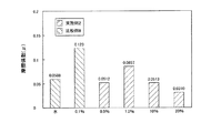
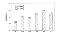
実施例1−1と同じように、ディスク試験片D、ボール試験片B、潤滑剤Lを準備した。実施例1−1と相違する点は、潤滑剤であり、実施例2の供給する潤滑剤を、水に対して、陰イオン界面活性剤として、アルカンスルホン酸塩から選択されるデカンスルホン酸ナトリウムを0.5質量%以上(具体的には、0.5質量%、1.0質量%、10質量%、20質量%)含有させた点である。そして、実施例1−1と同様の摩擦試験条件で摩擦係数を測定した。実施例1−1と相違する条件は、摺動速度を3.14×10⁻²m/sにした点である。この結果を図4に示す。また、試験終了後、各ディスク試験片Dを試験機30から取り出して、原子間力顕微鏡(AFM)を用いて、CNx被膜に形成された摩耗痕の断面積を求めて、この被膜の比摩耗量を算出した。この結果を、図5に示す。
(Example 2)
A disk test piece D, a ball test piece B, and a lubricant L were prepared in the same manner as in Example 1-1. The difference from Example 1-1 is a lubricant. The lubricant supplied in Example 2 is selected from alkane sulfonates as an anionic surfactant with respect to water, and sodium decane sulfonate. Is 0.5% by mass or more (specifically, 0.5% by mass, 1.0% by mass, 10% by mass, 20% by mass). And the friction coefficient was measured on the friction test conditions similar to Example 1-1. The condition different from that of Example 1-1 is that the sliding speed is set to 3.14 × 10 −2 m / s. The result is shown in FIG. Further, after the test is completed, each disk specimen D is taken out from the
(比較例8)
実施例2と同じように、ディスク試験片D、ボール試験片B、潤滑剤Lを準備した。実施例2と相違する点は、水に対して、前記陰イオン界面活性剤を添加しない水のみ潤滑剤と、陰イオン界面活性剤を0.1質量%含有させた潤滑剤を準備した点である。そして、実施例2と同じように、摩擦係数及び比摩耗量を測定した。この結果を図4及び図5に示す。
(Comparative Example 8)
In the same manner as in Example 2, a disk test piece D, a ball test piece B, and a lubricant L were prepared. The difference from Example 2 is that a water-only lubricant without adding the anionic surfactant to water and a lubricant containing 0.1% by mass of an anionic surfactant were prepared. is there. In the same manner as in Example 2, the friction coefficient and the specific wear amount were measured. The results are shown in FIGS.
(結果2及び考察2)
図4に示すように、比較例8の陰イオン界面活性剤を0.1質量%含有させた場合には、実施例8のいずれの場合よりも、摩擦係数が増加した。一方、図5に示すように、比較例8の陰イオン界面活性剤を0.1質量%含有させた場合、及び、実施例2の陰イオン界面活性剤を0.5質量%以上含有させた場合のいずれの場合であっても、比較例8の水潤滑下に比べ、比摩耗量は減少し、陰イオン界面活性剤の含有率を増加させるに従って摩擦係数は減少している。この結果から、摺動構造の潤滑剤として、水に陰イオン界面活性剤を含有させた潤滑剤を用いることにより、摺動部材の表面に形成させたCNx被膜(硬質炭素被膜)の摩耗を抑制することが可能であり、さらに、陰イオン界面活性剤を0.5質量%以上含有させた潤滑剤を用いることにより、摩擦係数をさらに減少させることができると考えられる。
(
As shown in FIG. 4, when 0.1 mass% of the anionic surfactant of Comparative Example 8 was contained, the friction coefficient was increased as compared with any case of Example 8. On the other hand, as shown in FIG. 5, the anionic surfactant of Comparative Example 8 was contained in an amount of 0.1% by mass, and the anionic surfactant of Example 2 was contained in an amount of 0.5% by mass or more. In any case, the specific wear amount decreased as compared with the case of water lubrication in Comparative Example 8, and the friction coefficient decreased as the content of the anionic surfactant was increased. From this result, by using a lubricant containing an anionic surfactant in water as a sliding structure lubricant, the wear of the CNx film (hard carbon film) formed on the surface of the sliding member is suppressed. In addition, it is considered that the friction coefficient can be further reduced by using a lubricant containing 0.5% by mass or more of an anionic surfactant.
(実施例3)
実施例2と同じように、ディスク試験片D、ボール試験片B、潤滑剤Lを準備した。実施例1−1と相違する点は、潤滑剤であり、実施例3の供給する潤滑剤を、水に対して、陽イオン界面活性剤として、アルキルトリメチルアンモニウム塩から選択されるテトラメチルアンモニウム塩を1.0質量%以上(具体的には、1.0質量%、10質量%、20質量%)含有させた点である。そして、実施例2と同じように、摩擦係数及び比摩耗量を測定した。この結果を図8及び図9に示す。
(Example 3)
In the same manner as in Example 2, a disk test piece D, a ball test piece B, and a lubricant L were prepared. The difference from Example 1-1 is a lubricant, and the lubricant supplied in Example 3 is selected from alkyltrimethylammonium salts as cationic surfactants with respect to water. Is 1.0 mass% or more (specifically, 1.0 mass%, 10 mass%, 20 mass%). In the same manner as in Example 2, the friction coefficient and the specific wear amount were measured. The results are shown in FIGS.
(比較例9)
実施例3と同じように、ディスク試験片D、ボール試験片B、潤滑剤Lを準備した。実施例3と相違する点は、水に対して、前記陽イオン界面活性剤を添加しない水のみ潤滑剤と、前記陽イオン界面活性剤を0.1質量%又は0.5質量%含有させた潤滑剤を準備した点である。そして、実施例3と同じように、摩擦係数及び比摩耗量を測定した。この結果を図6及び図7に示す。
(Comparative Example 9)
As in Example 3, a disk specimen D, a ball specimen B, and a lubricant L were prepared. The difference from Example 3 is that the water-only lubricant to which the cationic surfactant is not added and 0.1% by mass or 0.5% by mass of the cationic surfactant are added to water. This is the point where a lubricant was prepared. Then, as in Example 3, the friction coefficient and the specific wear amount were measured. The results are shown in FIGS.
(結果3及び考察3)
図6に示すように、陽イオン界面活性剤を含有させたものは、いずれも、比較例9の水潤滑下のものに比べて摩擦係数が増加しており、陽イオン界面活性剤の含有率を増加させるに従って摩擦係数は増加する傾向にあった。一方、図7に示すように、比較例9のうち、陽イオン界面活性剤を0.1質量%、0.5質量%含有させた場合は、水潤滑下の場合よりも、比摩耗量が増加した。しかし、実施例3に示すように、陽イオン界面活性剤を1.0質量%以上含有させた場合には、比較例9のいずれの場合に比べても、比摩耗量は減少した。この結果から、摺動構造の潤滑剤として、水に陽イオン界面活性剤を含有させた潤滑剤を用いることにより、摺動部材の表面に形成させたCNx被膜(硬質炭素被膜)の摩耗を抑制することができると考えられる。
(Result 3 and discussion 3)
As shown in FIG. 6, any of the surfactants containing the cationic surfactant has an increased coefficient of friction as compared with the water-lubricated one of Comparative Example 9, and the content of the cationic surfactant. The coefficient of friction tended to increase with increasing. On the other hand, as shown in FIG. 7, in Comparative Example 9, when the cationic surfactant was contained in an amount of 0.1% by mass and 0.5% by mass, the specific wear amount was higher than that in the case of water lubrication. Increased. However, as shown in Example 3, when the cationic surfactant was contained in an amount of 1.0% by mass or more, the specific wear amount was reduced as compared with any case of Comparative Example 9. From this result, by using a lubricant containing a cationic surfactant in water as a sliding structure lubricant, the wear of the CNx coating (hard carbon coating) formed on the surface of the sliding member is suppressed. I think it can be done.
(実施例4)
実施例2と同じように、ディスク試験片D、ボール試験片B、潤滑剤Lを準備した。実施例1−1と相違する点は、潤滑剤であり、実施例3の供給する潤滑剤を、水に対して、非イオン界面活性剤として、ポリオキシエチレンアルキルエーテルから選択されるポリオキシエチレンラウリルエーテルを0.5質量%以上(具体的には、0.5質量%,1.0質量%、10質量%、20質量%)含有させた点である。そして、実施例2と同じように、摩擦係数及び比摩耗量を測定した。この結果を図8及び図9に示す。
Example 4
In the same manner as in Example 2, a disk test piece D, a ball test piece B, and a lubricant L were prepared. The difference from Example 1-1 is a lubricant, and the lubricant supplied in Example 3 is selected from polyoxyethylene alkyl ether as a nonionic surfactant with respect to water. This is that 0.5% by mass or more (specifically, 0.5% by mass, 1.0% by mass, 10% by mass, 20% by mass) of lauryl ether is contained. In the same manner as in Example 2, the friction coefficient and the specific wear amount were measured. The results are shown in FIGS.
(比較例10)
実施例3と同じように、ディスク試験片D、ボール試験片B、潤滑剤Lを準備した。実施例2と相違する点は、水に対して、前記非イオン界面活性剤を添加しない水のみ潤滑剤と、前記非イオン界面活性剤を0.1質量%含有させた潤滑剤を準備した点である。そして、実施例3と同じように、摩擦係数及び比摩耗量を測定した。この結果を図8及び図9に示す。
(Comparative Example 10)
As in Example 3, a disk specimen D, a ball specimen B, and a lubricant L were prepared. The difference from Example 2 is that a water-only lubricant not containing the nonionic surfactant with respect to water and a lubricant containing 0.1% by mass of the nonionic surfactant were prepared. It is. Then, as in Example 3, the friction coefficient and the specific wear amount were measured. The results are shown in FIGS.
(結果4及び考察4)
図8に示すように、比較例10のうち、非イオン界面活性剤を0.1質量%含有させた場合には、水潤滑下の場合に比べて、摩擦係数が増加した。さらに、実施例4のうち、非イオン界面活性剤を10質量%以上含有させた場合には、他の場合に比べて、摩擦係数は減少した。一方、図9に示すように、比較例10に比べて、実施例4のように、非イオン界面活性剤を0.5質量%以上含有させた潤滑剤を用い方が、比摩耗量は減少した。この結果から、この結果から、非イオン界面活性剤を0.5質量%以上含有させた場合には、摺動部材の表面に形成させたCNx被膜(硬質炭素被膜)の摩耗を抑制することが可能であり、さらに、非イオン界面活性剤を10質量%以上含有させた場合には、摺動部材の摩擦係数をさらに減少させることができると考えられる。
(Result 4 and Discussion 4)
As shown in FIG. 8, in Comparative Example 10, when 0.1% by mass of the nonionic surfactant was contained, the friction coefficient increased as compared with the case under water lubrication. Furthermore, in Example 4, when the nonionic surfactant was contained in an amount of 10% by mass or more, the friction coefficient decreased compared to other cases. On the other hand, as shown in FIG. 9, compared to Comparative Example 10, the amount of specific wear is reduced by using a lubricant containing 0.5% by mass or more of a nonionic surfactant as in Example 4. did. From this result, it can be seen from this result that when 0.5% by mass or more of the nonionic surfactant is contained, the wear of the CNx film (hard carbon film) formed on the surface of the sliding member is suppressed. Further, it is considered that when the nonionic surfactant is contained in an amount of 10% by mass or more, the friction coefficient of the sliding member can be further reduced.
以上、本発明の実施例を詳述してきたが、具体的な構成はこの実施例に限定されるものではなく、本発明の要旨を逸脱しない範囲における設計変更があっても、それらは本発明に含まれるものである。 As mentioned above, although the embodiment of the present invention has been described in detail, the specific configuration is not limited to this embodiment, and even if there is a design change within a scope not departing from the gist of the present invention, they are not limited to the present invention. Is included.
たとえば、本実施例では、一方の摺動部材の基材としてシリコンウェハに硬質炭素被膜を成膜したが、硬質炭素被膜が摺動時において剥離、亀裂の発生等がないのであれば、鉄等の金属材料に被覆してもよい。また、一対の摺動部材の双方の摺動面に硬質炭素被膜を形成する必要はなく、いずれか一方の摺動面にのみ硬質炭素被膜を成膜してもよい。 For example, in this example, a hard carbon film was formed on a silicon wafer as a base material of one sliding member. However, if the hard carbon film does not peel or crack when sliding, iron, etc. The metal material may be coated. Moreover, it is not necessary to form the hard carbon film on both sliding surfaces of the pair of sliding members, and the hard carbon film may be formed only on one of the sliding surfaces.
10:イオンビームミキシング装置、11:真空チャンバ、12:ホルダ、13:支持台,14:アシスト用イオン源及びガス供給源,15:スパッタイオン源、16:クライオポンプ、30:ピンオンディスク摩擦試験機、31:ボールホルダー、32:ディスクホルダー、33:ステージ、34:ひずみゲージ、35:平行板ばね,37:モータ、38:カップリング、B:ボール試験片(摺動部材)、D:ディスク試験片(摺動部材)、S:シリコンウェハ(基材)、T:カーボンターゲット 10: Ion beam mixing device, 11: Vacuum chamber, 12: Holder, 13: Support base, 14: Assist ion source and gas supply source, 15: Sputter ion source, 16: Cryo pump, 30: Pin-on-disk friction test Machine: 31: Ball holder, 32: Disc holder, 33: Stage, 34: Strain gauge, 35: Parallel leaf spring, 37: Motor, 38: Coupling, B: Ball specimen (sliding member), D: Disc Test piece (sliding member), S: silicon wafer (base material), T: carbon target
Claims (8)
前記潤滑剤は、界面活性剤が含有した水を少なくとも含むことを特徴とする摺動構造。 A slide provided with a pair of sliding members having a hard carbon film formed on at least one of the sliding surfaces sliding relative to each other, and a lubricant present between the pair of sliding members. Dynamic structure,
The sliding structure characterized in that the lubricant contains at least water contained in a surfactant.
Priority Applications (1)
| Application Number | Priority Date | Filing Date | Title |
|---|---|---|---|
| JP2007179798A JP5118906B2 (en) | 2007-07-09 | 2007-07-09 | Sliding structure |
Applications Claiming Priority (1)
| Application Number | Priority Date | Filing Date | Title |
|---|---|---|---|
| JP2007179798A JP5118906B2 (en) | 2007-07-09 | 2007-07-09 | Sliding structure |
Publications (2)
| Publication Number | Publication Date |
|---|---|
| JP2009013371A JP2009013371A (en) | 2009-01-22 |
| JP5118906B2 true JP5118906B2 (en) | 2013-01-16 |
Family
ID=40354664
Family Applications (1)
| Application Number | Title | Priority Date | Filing Date |
|---|---|---|---|
| JP2007179798A Expired - Fee Related JP5118906B2 (en) | 2007-07-09 | 2007-07-09 | Sliding structure |
Country Status (1)
| Country | Link |
|---|---|
| JP (1) | JP5118906B2 (en) |
Families Citing this family (1)
| Publication number | Priority date | Publication date | Assignee | Title |
|---|---|---|---|---|
| JP5738737B2 (en) * | 2011-10-19 | 2015-06-24 | コスモ石油ルブリカンツ株式会社 | Aqueous lubricant composition |
Family Cites Families (6)
| Publication number | Priority date | Publication date | Assignee | Title |
|---|---|---|---|---|
| US4274973A (en) * | 1979-06-22 | 1981-06-23 | The Diversey Corporation | Aqueous water-soluble soap lubricant concentrates and aqueous lubricants containing same |
| GB8926885D0 (en) * | 1989-11-28 | 1990-01-17 | Albright & Wilson | Drilling fluids |
| JP3973720B2 (en) * | 1996-11-07 | 2007-09-12 | 三洋化成工業株式会社 | Hydrous lubricant |
| JP4242610B2 (en) * | 2002-07-09 | 2009-03-25 | 協同油脂株式会社 | Water-soluble lubricant composition |
| JP2007136511A (en) * | 2005-11-18 | 2007-06-07 | Toyota Central Res & Dev Lab Inc | Cold working method |
| JP5336178B2 (en) * | 2006-04-28 | 2013-11-06 | 日産自動車株式会社 | Low friction lubrication assembly |
-
2007
- 2007-07-09 JP JP2007179798A patent/JP5118906B2/en not_active Expired - Fee Related
Also Published As
| Publication number | Publication date |
|---|---|
| JP2009013371A (en) | 2009-01-22 |
Similar Documents
| Publication | Publication Date | Title |
|---|---|---|
| EP2014748B1 (en) | Low-friction lubrication assembly | |
| Yang et al. | Friction and wear performance of titanium alloy against tungsten carbide lubricated with phosphate ester | |
| Sutton et al. | The friction of diamond-like carbon coatings in a water environment | |
| JP5273337B2 (en) | Low friction sliding member | |
| JP5763190B2 (en) | Method for providing a low friction surface | |
| WO2012073717A1 (en) | Sliding structural members | |
| BR102012016191A2 (en) | SLIDING ELEMENT WITH DLC COATING | |
| Katahira et al. | ELID grinding and tribological characteristics of TiAlN film | |
| Mo et al. | Tribological investigation of WC/C coating under dry sliding conditions | |
| JP2007262560A (en) | Method for coating hard film having low-friction characteristics and peel resistance, and coated member with the hard film | |
| JP6095090B2 (en) | Sliding method, manufacturing method of sliding structure, sliding structure and device | |
| CN104812925B (en) | With enhanced antifriction and the electric arc PVD coatings for subtracting abrasive nature | |
| JP5118906B2 (en) | Sliding structure | |
| JP2008255160A (en) | Sliding structure | |
| Luo et al. | Advanced tribology: proceedings of CIST2008 & ITS-IFToMM2008 | |
| JP2006008853A (en) | Hard carbon film sliding member and method for producing the same | |
| JP5221067B2 (en) | Sliding structure | |
| JP6298019B2 (en) | Manufacturing method of sliding member | |
| JP4915891B2 (en) | Low friction sliding member | |
| Lind et al. | Tribological properties of PVD coatings with lubricating films | |
| Chinas-Castillo et al. | Friction reduction by water-soluble ammonium thiometallates | |
| Mannan et al. | Tribological performance of DLC/DLC and steel/DLC contacts in the presence of additivated oil | |
| JP5703951B2 (en) | Processing fluid and cold plastic working method using the same | |
| Khun et al. | Effects of platinum content on tribological properties of platinum/nitrogen doped diamond-like carbon thin films deposited via magnetron sputtering | |
| JP2007070565A (en) | Sliding unit and sliding method |
Legal Events
| Date | Code | Title | Description |
|---|---|---|---|
| A621 | Written request for application examination |
Free format text: JAPANESE INTERMEDIATE CODE: A621 Effective date: 20100610 |
|
| A521 | Written amendment |
Free format text: JAPANESE INTERMEDIATE CODE: A821 Effective date: 20100610 |
|
| TRDD | Decision of grant or rejection written | ||
| A01 | Written decision to grant a patent or to grant a registration (utility model) |
Free format text: JAPANESE INTERMEDIATE CODE: A01 Effective date: 20121002 |
|
| A01 | Written decision to grant a patent or to grant a registration (utility model) |
Free format text: JAPANESE INTERMEDIATE CODE: A01 |
|
| A61 | First payment of annual fees (during grant procedure) |
Free format text: JAPANESE INTERMEDIATE CODE: A61 Effective date: 20121022 |
|
| FPAY | Renewal fee payment (event date is renewal date of database) |
Free format text: PAYMENT UNTIL: 20151026 Year of fee payment: 3 |
|
| R250 | Receipt of annual fees |
Free format text: JAPANESE INTERMEDIATE CODE: R250 |
|
| R250 | Receipt of annual fees |
Free format text: JAPANESE INTERMEDIATE CODE: R250 |
|
| LAPS | Cancellation because of no payment of annual fees |