JP5117399B2 - Tissue graft fixation - Google Patents
Tissue graft fixation Download PDFInfo
- Publication number
- JP5117399B2 JP5117399B2 JP2008547764A JP2008547764A JP5117399B2 JP 5117399 B2 JP5117399 B2 JP 5117399B2 JP 2008547764 A JP2008547764 A JP 2008547764A JP 2008547764 A JP2008547764 A JP 2008547764A JP 5117399 B2 JP5117399 B2 JP 5117399B2
- Authority
- JP
- Japan
- Prior art keywords
- surgical device
- hole
- kit
- diameter
- concave
- Prior art date
- Legal status (The legal status is an assumption and is not a legal conclusion. Google has not performed a legal analysis and makes no representation as to the accuracy of the status listed.)
- Active
Links
Images


Classifications
-
- A—HUMAN NECESSITIES
- A61—MEDICAL OR VETERINARY SCIENCE; HYGIENE
- A61B—DIAGNOSIS; SURGERY; IDENTIFICATION
- A61B17/00—Surgical instruments, devices or methods, e.g. tourniquets
- A61B17/04—Surgical instruments, devices or methods, e.g. tourniquets for suturing wounds; Holders or packages for needles or suture materials
- A61B17/0401—Suture anchors, buttons or pledgets, i.e. means for attaching sutures to bone, cartilage or soft tissue; Instruments for applying or removing suture anchors
-
- A—HUMAN NECESSITIES
- A61—MEDICAL OR VETERINARY SCIENCE; HYGIENE
- A61F—FILTERS IMPLANTABLE INTO BLOOD VESSELS; PROSTHESES; DEVICES PROVIDING PATENCY TO, OR PREVENTING COLLAPSING OF, TUBULAR STRUCTURES OF THE BODY, e.g. STENTS; ORTHOPAEDIC, NURSING OR CONTRACEPTIVE DEVICES; FOMENTATION; TREATMENT OR PROTECTION OF EYES OR EARS; BANDAGES, DRESSINGS OR ABSORBENT PADS; FIRST-AID KITS
- A61F2/00—Filters implantable into blood vessels; Prostheses, i.e. artificial substitutes or replacements for parts of the body; Appliances for connecting them with the body; Devices providing patency to, or preventing collapsing of, tubular structures of the body, e.g. stents
- A61F2/02—Prostheses implantable into the body
- A61F2/08—Muscles; Tendons; Ligaments
- A61F2/0811—Fixation devices for tendons or ligaments
-
- A—HUMAN NECESSITIES
- A61—MEDICAL OR VETERINARY SCIENCE; HYGIENE
- A61B—DIAGNOSIS; SURGERY; IDENTIFICATION
- A61B17/00—Surgical instruments, devices or methods, e.g. tourniquets
- A61B17/04—Surgical instruments, devices or methods, e.g. tourniquets for suturing wounds; Holders or packages for needles or suture materials
- A61B17/0401—Suture anchors, buttons or pledgets, i.e. means for attaching sutures to bone, cartilage or soft tissue; Instruments for applying or removing suture anchors
- A61B2017/0404—Buttons
-
- A—HUMAN NECESSITIES
- A61—MEDICAL OR VETERINARY SCIENCE; HYGIENE
- A61F—FILTERS IMPLANTABLE INTO BLOOD VESSELS; PROSTHESES; DEVICES PROVIDING PATENCY TO, OR PREVENTING COLLAPSING OF, TUBULAR STRUCTURES OF THE BODY, e.g. STENTS; ORTHOPAEDIC, NURSING OR CONTRACEPTIVE DEVICES; FOMENTATION; TREATMENT OR PROTECTION OF EYES OR EARS; BANDAGES, DRESSINGS OR ABSORBENT PADS; FIRST-AID KITS
- A61F2/00—Filters implantable into blood vessels; Prostheses, i.e. artificial substitutes or replacements for parts of the body; Appliances for connecting them with the body; Devices providing patency to, or preventing collapsing of, tubular structures of the body, e.g. stents
- A61F2/02—Prostheses implantable into the body
- A61F2/08—Muscles; Tendons; Ligaments
- A61F2/0811—Fixation devices for tendons or ligaments
- A61F2002/0817—Structure of the anchor
- A61F2002/0823—Modular anchors comprising a plurality of separate parts
Abstract
Description
本出願は、2005年12月22日に出願された米国特許出願第11/313716号のPCT国際出願である。各出願の開示は、その全体が参照により組み込まれる。 This application is a PCT international application for US patent application Ser. No. 11 / 313,716 filed on Dec. 22, 2005. The disclosure of each application is incorporated by reference in its entirety.
本発明は、一般に組織移植片の固定、より詳細には組織移植片を固定するために使用される移植片固定部材に関する。 The present invention relates generally to fixation of tissue grafts, and more particularly to graft fixation members used to secure tissue grafts.
断裂して修復不可能な前十字靱帯(ACL)は、一般に組織移植片によって関節鏡視下で交換される。組織移植片は、各端部にいわゆる「骨ブロック(bone block)」を有する膝蓋腱の一部および半腱様の筋および薄筋から採取することができる。あるいは、組織移植片は、合成材料または合成と天然の材料との混合物から形成することができる。交換組織移植片は、大腿骨の中の通路内に形成された受け口の中に組織移植片の一端を固定して、脛骨内に形成された通路内に移植片の他端を通過させることによって移植される。一般に、縫合糸は、組織移植片の各端部を固定具(例えばインターフェランススクリュー(interference screw)またはポスト(post))に取り付けるために使用され、固定具は、骨に固定される。 An anterior cruciate ligament (ACL) that is torn and cannot be repaired is generally replaced arthroscopically by a tissue graft. Tissue grafts can be taken from a portion of the patella tendon having a so-called “bone block” at each end, and semi-tendon-like muscles and thin muscles. Alternatively, the tissue graft can be formed from a synthetic material or a mixture of synthetic and natural materials. The replacement tissue graft is fixed by passing one end of the graft through the passage formed in the tibia, with one end of the tissue graft secured in a receptacle formed in the passage in the femur. Transplanted. In general, a suture is used to attach each end of a tissue graft to a fastener (eg, an interference screw or post), which is secured to the bone.
また、その全体が参照により本明細書に組み込まれる特許文献1に記載されるように、例えば固定ボタン(fixation button)などの移植片固定部材を使用して大腿骨の皮質に組織移植片を固定することが知られている。固定ボタンを使用する際、大腿骨の通路は、一般に移植片を受けるために比較的大きな直径部分、および組織移植片から固定ボタンまで延びる縫合糸の長さを受けるために大腿骨の皮質付近でチャネルを通過するより小さい直径を有する。大腿骨の通路の全長と大腿骨の通路の長い方の直径部分の長さとを測定することによって、外科医は、固定ボタンを組織移植片に取り付けるための縫合素材の適切な長さを決定する。 Also, as described in U.S. Patent No. 6,057,086, the entirety of which is incorporated herein by reference, a tissue graft is fixed to the cortex of the femur using, for example, a graft fixing member such as a fixation button. It is known to do. When using a fixation button, the femoral passage is generally near the femoral cortex to receive a relatively large diameter portion to receive the graft and a length of suture extending from the tissue graft to the fixation button. It has a smaller diameter that passes through the channel. By measuring the total length of the femoral passage and the length of the longer diameter portion of the femoral passage, the surgeon determines the appropriate length of suture material for attaching the fixation button to the tissue graft.
当技術分野には、均一の直径を有する大腿骨の通路内で組織移植片の固定を可能にする部材に対する要望がある。これは、2つの通過チャネルの形成の必要性を回避し、これにより縫合糸材料の長さの測定は言うまでもなく、2つの別個のドリルの使用も回避される。さらに、このタイプの固定部材は、同様に大腿骨の外側の大腿骨受け口のドリル穿孔を可能にする。現在、上記の長い方の直径部分は、大腿骨表面で等測の位置に配置し、頸骨通路を通って大腿骨内にガイドワイヤを突き通し、短縮されたドリルヘッドを有するドリルを使用することによって、開口を有し端部が閉鎖された大腿骨受け口を形成することによって形成される。小さい方の直径部分は、カニューレが挿入された通過ピンを大腿骨皮質の上部まで進め、大腿四頭筋および皮膚を貫通させることによって形成される。これらの部分の形成は、上記のタイプの固定部材が使用される場合、必須ではない。代わりに、均一の直径を有する単一の部分を、大腿骨の外側からの最初のドリル穿孔によって形成することができる。この外側のドリル穿孔は、小児科の場合に骨端を交差することを阻止するのに特に有益である。
上記の問題に鑑みて、本発明が開発された。本開示は、大腿骨通路内で組織移植片を固定するために使用される外科的デバイスに関連する。 In view of the above problems, the present invention has been developed. The present disclosure relates to a surgical device used to secure a tissue graft within a femoral passage.
本発明の一態様において、外科的デバイスは、向かい合わせの第1および第2面を有する部材を有する。部材は、第1面が凹面部を有する中間部を有する。中間部は、凹面部から第2面まで延在する穴を形成する。端部が中間部から延在し、各端部は、第1面から第2面まで延在する穴を形成する。外科的デバイスは、凹面部内に受けられるような大きさにされた第2部材を有する。中間部は、凹面部から第2面まで延在する2つの補助穴を形成する。部材は、第2面上に先細の表面部を有する。中間部の穴は細長い。 In one aspect of the invention, the surgical device has a member having opposed first and second surfaces. The member has an intermediate portion having a concave portion on the first surface. The intermediate portion forms a hole extending from the concave surface portion to the second surface. The end portions extend from the intermediate portion, and each end portion forms a hole extending from the first surface to the second surface. The surgical device has a second member sized to be received in the concave portion. The intermediate portion forms two auxiliary holes extending from the concave surface portion to the second surface. The member has a tapered surface portion on the second surface. The middle hole is elongated.
本開示の他の態様において、外科的デバイスは、第1および第2の部材を有する。第1部材は、向かい合わせの第1および第2の面と、第1面内の凹面部と、凹面部から第2面まで延在する穴とを有する。第2部材は穴を形成し、第1部材の凹面部内に受けられるように構成される。穴は、第2部材が凹面部内に受けられる際、軸方向に整列されて配置される。凹面部は、第2部材とスナップ嵌合または締り嵌めを形成するように構成される。外科的デバイスは、穴を通って延在する縫合糸を有する。第1部材は、少なくとも2つの補助穴、例えば全部で5つの穴を形成する。第2部材は、3つの補助穴を形成する。第1部材は、その第1部材の第2面の上にテーパ状の表面部を有する。 In other aspects of the present disclosure, the surgical device has first and second members. The first member has first and second surfaces facing each other, a concave surface portion in the first surface, and a hole extending from the concave surface portion to the second surface. The second member is configured to form a hole and be received within the concave portion of the first member. The holes are arranged in axial alignment when the second member is received in the concave portion. The concave surface portion is configured to form a snap fit or an interference fit with the second member. The surgical device has a suture that extends through the hole. The first member forms at least two auxiliary holes, for example, a total of five holes. The second member forms three auxiliary holes. The first member has a tapered surface portion on the second surface of the first member.
本開示のさらなる態様において、外科的デバイスは、約6mmから約10mmの均一の直径を有する大腿骨通路内で組織移植片を固定するのに使用される。他の態様において、外科的デバイスは、第1の直径の第1通過チャネルと第1の直径より小さい第2の直径の第2通過チャネルとを有する大腿骨通路内で組織移植片を固定するのに使用される。本開示の他の態様において、凹面部は、異なる形状およびサイズを有する。 In a further aspect of the present disclosure, the surgical device is used to secure a tissue graft within a femoral passage having a uniform diameter of about 6 mm to about 10 mm. In another aspect, the surgical device secures the tissue graft within a femoral passage having a first passage channel having a first diameter and a second passage channel having a second diameter that is smaller than the first diameter. Used for. In other aspects of the present disclosure, the concave portions have different shapes and sizes.
本開示の一態様において、方法は、組織固定デバイスを開口で骨穴に配置するステップであって、組織固定デバイスが、可撓性部材、例えば縫合糸によって組織移植片に結合されるステップと、組織固定デバイスを、可撓性部材を受けるための穴を有するより大きなデバイス内に配置することによって組織固定デバイスのサイズを増大させるステップと、を、有する。この態様は、組織固定デバイスを開口に配置する前に組織固定デバイスのサイズを増大させるステップを有してもよい。 In one aspect of the present disclosure, the method includes placing a tissue fixation device in the bone hole with an opening, wherein the tissue fixation device is coupled to the tissue graft by a flexible member, such as a suture. Increasing the size of the tissue fixation device by placing the tissue fixation device in a larger device having a hole for receiving the flexible member. This aspect may include increasing the size of the tissue fixation device prior to placing the tissue fixation device in the opening.
本開示の他の態様において、キットは、少なくとも1つの外科的デバイスを含む。外科的デバイスは、第1および第2部材を有する。第1部材は、向かい合わせの第1および第2の面と、第1面内の凹面部と、凹面部から第2面まで延在する穴とを有する。第2部材は穴を形成し、第1部材の凹面部内に受けられるように構成される。穴は、第2部材が凹面部内に受けられる際、軸方向に整列されて配置される。凹面部は、第2部材とスナップ嵌合または締り嵌めを形成するように構成される。外科的デバイスは、穴を通って延在する縫合糸を有する。第1部材は、少なくとも2つの補助穴、例えば全部で5つの穴を形成する。第2部材は、3つの補助穴を形成する。第1部材は、その第1部材の第2面の上にテーパ状の表面部を有する。 In other aspects of the present disclosure, the kit includes at least one surgical device. The surgical device has first and second members. The first member has first and second surfaces facing each other, a concave surface portion in the first surface, and a hole extending from the concave surface portion to the second surface. The second member is configured to form a hole and be received within the concave portion of the first member. The holes are arranged in axial alignment when the second member is received in the concave portion. The concave surface portion is configured to form a snap fit or an interference fit with the second member. The surgical device has a suture that extends through the hole. The first member forms at least two auxiliary holes, for example, a total of five holes. The second member forms three auxiliary holes. The first member has a tapered surface portion on the second surface of the first member.
外科的デバイスは、約6mmから約10mmの均一の直径を有する大腿骨通路内で組織移植片を固定するのに使用される。他の態様において、外科的デバイスは、第1の直径の第1通過チャネルと第1の直径より小さい第2の直径の第2通過チャネルとを有する大腿骨通路内で組織移植片を固定するのに使用される。本開示の他の態様において、凹面部は、異なる形状およびサイズを有する。 The surgical device is used to secure a tissue graft within a femoral passage having a uniform diameter of about 6 mm to about 10 mm. In another aspect, the surgical device secures the tissue graft within a femoral passage having a first passage channel having a first diameter and a second passage channel having a second diameter that is smaller than the first diameter. Used for. In other aspects of the present disclosure, the concave portions have different shapes and sizes.
本開示は、従来のデバイスおよび技術に対するいくつかの利点を有する。第一に、外科的デバイスは、約6mmから約10mmの均一の直径を有する大腿骨通路内で組織移植片を固定することが可能である。これは、2つのドリルの使用、および上記の現在の処置で行われるような縫合糸材料の長さの測定の必要性をなくす。第二に、外科的デバイスは、皮質領域の穿孔にもかかわらず、内視鏡処置を続けることが可能である。第三に、外科的デバイスは、大腿骨の外側にドリル穿孔することが可能である。 The present disclosure has several advantages over conventional devices and techniques. First, the surgical device is capable of securing a tissue graft within a femoral passage having a uniform diameter of about 6 mm to about 10 mm. This eliminates the need to use two drills and to measure the length of the suture material as is done in the current procedure described above. Second, the surgical device can continue the endoscopic procedure despite perforation of the cortical region. Third, the surgical device can be drilled outside the femur.
本発明の他の特徴、態様および利点、ならびに本発明の種々の実施形態の構造および操作は、添付の図面を参照して以下により詳細に記載される。 Other features, aspects and advantages of the present invention, as well as the structure and operation of various embodiments of the present invention, are described in more detail below with reference to the accompanying drawings.
明細書に組み込まれ、その一部を形成する添付の図面は、説明と共に本発明の実施形態を示し、本発明の原理を説明する役割を持つ。 The accompanying drawings, which are incorporated in and form a part of the specification, illustrate embodiments of the present invention and, together with the description, serve to explain the principles of the invention.
同様の参照符号が同様の要素を示す添付の図面を参照すると、図1は、縫合糸30によって組織移植片20の骨ブロック22に接続される固定部材90であって大腿骨通路14内に移植片20に固定するために大腿骨通路14の開口17の上に配置される固定部材90を示す。固定部材90は、例えばワッシャー110など第1部材内に受けられる、例えばボタン100などの第2部材を有する。特許文献1に記載されるような大腿骨内での通過チャネルのドリル穿孔を含む技法と比較すると、固定部材90により大腿骨通路14はほぼ均一の直径を有することが可能になり、これにより比較的小さい通過チャネルを測定してドリル穿孔する追加のステップがなくなる。
Referring to the accompanying drawings, wherein like reference numerals indicate like elements, FIG. 1 is a
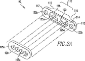
図2Aから図3Bを参照すると、ワッシャー110は全体的に細長い形状を有しており、中間部111、および中間部111から延出する端部112を有する。ワッシャー110は、反対側に置かれた第1および第2面114、115を有し、中間部111は、ボタン100を受けるための凹面部116を有する。中間部111は、好ましくは中央に位置し、移植組織片縫合糸30を受けるために凹面部116から第2面115まで延在する穴120を有する。ワッシャー110は、引張縫合糸45(図4)を受けるために、各端部112内の1つの穴125b、および中央穴120の両側における中間部111内の2つの内側穴125aの4つの補助穴を形成する。穴125は、ワッシャーの第1面114から第2面115まで延在する。
Referring to FIGS. 2A to 3B, the
ワッシャー面115は、端部112から中間部111までテーパ状にされる(図7C参照)。使用中、ワッシャー面115は、大腿骨通路に面し、ワッシャーの中間部111は、大腿骨通路14の開口17内に受けられる。このテーパ状によって、骨表面に対して低姿勢を維持しつつ、ワッシャー端部112を骨表面に接触させて固定部材90を大腿骨通路14の開口17にしっかりと係合することが可能になる。このテーパ状によって、固定部材90と一定の直径を有する通路開口17間の緊密な嵌合が容易にする。したがって、テーパ状部により、移植片固定部材のサイズを大腿骨通路開口に精密に適合させる必要性が低下する。しかしながら、ワッシャーは、テーパ状部を必ずしも有する必要はない。
The
ボタン100は、4つの穴を形成する。ボタン100がワッシャー凹部116内に配置される際にワッシャー中央穴120と整列する2つの中央穴105a、および内側ワッシャー穴125aの1つとそれぞれ整列する2つの端部穴105bがある。細長いワッシャー110は、例えば成人大腿骨の場合、ワッシャー110は、約15から30mmの例えば20mmの長さ、約6から10mmの例えば6mmの幅、約1から4mmの厚みの例えば3mmの長さL、幅Wおよび厚みTを有し、大腿骨通路14の全長にまたがり、大腿骨12の表面に対して相対的に低姿勢を維持しながら組織移植片20を保持する縫合糸に適切な張力をかけるように十分な剛性を提供する。ワッシャー凹部116は、例えばスナップ嵌合または締り嵌めによってボタン100を受けるような大きさにされ、ボタンがワッシャー110の表面114と同一面になるように、ボタンの厚みと一致する深さを有する。
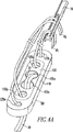
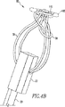
図4Aおよび図4Bを参照すると、ボタン100/ワッシャー110の結合体は、ワッシャー穴120(図示せず)を通って延出し、ボタン穴105aの中をくぐる2本の閉鎖ループ縫合糸30によって形成される。また、移植片固定部材90は、1本の縫合糸45がワッシャー穴125bの1つを通って、隣接するワッシャー穴125a、および対応するボタン穴105bを通って戻り、同様に第2の縫合糸45が、反対側のワッシャーおよびボタンの穴の中をくぐることによって形成される。このとき、縫合糸45は、以下でより詳細に記載するように通過ピン50の近位端に配置される開口を通って進む。あるいは、操作室のスタッフが縫合糸45を通すことができる。図6は、1本の縫合糸45がワッシャー穴125bのそれぞれに通される縫合糸45の代替の通し方を示す。ここでは、ワッシャー穴125aおよびボタン穴105bは使用されない。
Referring to FIGS. 4A and 4B, the
図5および図6を参照すると、使用中、ほぼ均一の直径の大腿骨穴17は、ドリル40を使用して穿孔される。移植片固定部材90および組織移植片20を頸骨および大腿骨通路を通って引っ張るために、通過ピン50などの縫合糸回収デバイスを使用して縫合糸45の自由端に取り外し可能に係合し、膝10の中で固定部材90を引っ張る。
With reference to FIGS. 5 and 6, in use, a generally uniform diameter femoral hole 17 is drilled using a
図1を参照すると、固定部材90が大腿骨通路14を通して引っ張られた後、外科医は、固定部材90を大腿骨通路14に対して横向きに開口17の両端にわたって配置する。組織移植片の固定を完全にするために、組織移植片20を頸骨13に接着し、特許文献1に記載される方法によって、組織移植片20および閉鎖ループ縫合糸30に張力をかけることで、固定部材90は、大腿骨12に対して固定される。
Referring to FIG. 1, after the
他の実施形態は、添付の特許請求の範囲の範囲内にある。例えば他の実施形態は、多様な形状のボタンを受けるために、適切な大きさにされかつ成形されたワッシャーを有してもよい。図7Aから図7Cを参照すると、凹部116内に中央穴120および縫合糸穴125aの両方を有する代わりに、ワッシャー710は、凹部716内にボタンの4つの穴105aおよび105bからの縫合糸を収容するような大きさにされかつ成形された中央穴720のみを含む。穴720は、穴105bからの縫合糸を受けるために、2つの側部に延在する開口722、724を有する。ワッシャー710は、ワッシャー710の端部712に縫合糸穴725bを有する。
Other embodiments are within the scope of the appended claims. For example, other embodiments may have washers that are appropriately sized and shaped to receive variously shaped buttons. Referring to FIGS. 7A-7C, instead of having both the
図8を参照すると、他の実施形態において、ワッシャー810は、凹部816内の細長い中央穴820および側部穴825bのみを有する。図9を参照すると、他の実施形態において、ワッシャー910は、ワッシャー710の穴720および725bと類似の中央穴920および側部穴925bを有する。他の実施形態において(図10Aから10C)、ワッシャー1010は、端部1012の円形の縫合糸穴1025b、および中央穴1020に隣接する凹部1016に長円形の縫合糸穴1025aを有する。
Referring to FIG. 8, in another embodiment,
上述の要素を有する少なくとも1つの外科的デバイスを含むキットは、本開示の範囲内である。 Kits comprising at least one surgical device having the above-described elements are within the scope of this disclosure.
上述の実施形態が単一の均一のサイズの大腿骨通路を有する処置に関連して記載されているが、移植片固定部材は、第1の直径を有する第1通路チャネル、およびより小さい第2の直径を有する第2通路チャネルが大腿骨通路内に形成される処置に適用することもできる。例えば、より小さい通過チャネルの形成は、例えば骨が成長過程にある子供、または比較的長い大腿骨通路14を収容するのに十分な骨密度のない高齢の患者など特定の患者に望ましい場合がある。これらの場合、移植片固定部材は、有利には、張力がかけられる骨の表面領域を増大させる。
Although the embodiments described above are described in connection with a procedure having a single uniform sized femoral passage, the graft fixation member includes a first passage channel having a first diameter, and a smaller second. Can be applied to procedures in which a second passage channel having a diameter of For example, the formation of smaller passage channels may be desirable for certain patients, such as children whose bones are growing, or elderly patients who do not have sufficient bone density to accommodate the relatively long
ワッシャーの凹部は、ボタンを完全にまたは部分的に受けるような大きさにされ成形される。ワッシャーは、異なるボタンを収容するために、異なるサイズおよび/または異なる形状を有して設けることができる。例えばワッシャー110の凹部116は、共に参照により本明細書に組み込まれる、米国特許第6533802号、および2004年7月20日に出願され米国公開特許第2005−0038427号として公開された米国特許出願第10/895266号に記載される固定ボタンを受けるような大きさにし、成形することができる。
The recess in the washer is sized and shaped to receive the button completely or partially. The washer can be provided with different sizes and / or different shapes to accommodate different buttons. For example, the
限定するものではないが、閉鎖ループ縫合糸30は、ポリエステルで作成された連続ループ、ループの縫合糸のより糸、またはループに結び合わされたポリエステルのクロージャテープ(例えばオハイオ州、シンシナティ、Ethicon社のMarselene(商標))の一片であってよい。
Without limitation, the
移植片固定部材は、チタニウムまたはPEEK(ポリエーテルエーテルケトン)などの生体適合性材料から形成される。 The graft fixation member is formed from a biocompatible material such as titanium or PEEK (polyetheretherketone).
固定部材は、例えば摘出された骨ブロックを持たない組織移植片など骨ブロックのもの以外の組織移植片、および合成材料から、または合成および天然材料の組合せから形成された組織移植片と共に使用することができる。 The fixation member is for use with tissue grafts other than those of bone blocks, such as tissue grafts without an excised bone block, and with tissue grafts formed from synthetic materials or a combination of synthetic and natural materials Can do.
上記を鑑み、本発明のいくつかの利点が実現され得られることがわかるであろう。 In view of the above, it will be seen that the several advantages of the invention are realized.
実施形態は、本発明の原理を最適に説明するために選択され記載され、したがってその実際の適用により、種々の実施形態、および企図される特定の使用法に適合された種々の変形形態で、当業者が、本発明を最適に利用することが可能になる。 The embodiments have been selected and described to best illustrate the principles of the invention, and thus, depending on their actual application, in various embodiments and in various variations adapted to the particular usage contemplated. One skilled in the art can optimally utilize the present invention.
本発明の範囲から逸脱することなく、本明細書に記載され示される構造および方法に種々の変形を行うことができ、これは、上記の説明に包含され、添付の図面に示される全ての事柄が限定ではなく例示として解釈されるべきであることを意図する。例えば図5は、固定ピン112の使用によってフレーム120に結合されたマウント110を示すが、これらの要素を一時的に一緒に固定するために、他の構造および/または方法を使用することもできる。したがって、本発明の広さおよび範囲は、上記に記載される例示の実施形態のいずれにも限定されるべきではないが、本明細書に添付される特許請求の範囲およびその等価物によってのみ規定されるべきである。
Various modifications may be made to the structures and methods described and shown herein without departing from the scope of the invention, including all that is encompassed by the above description and shown in the accompanying drawings. Is intended to be construed as illustrative rather than limiting. For example, FIG. 5 shows the
10 膝
12 大腿骨
13 頸骨
14 大腿骨通路、第1通過チャネル、骨穴
17 開口、大腿骨穴
20 組織移植片
22 骨ブロック
30 可撓性部材、縫合糸
40 ドリル
45 縫合糸
50 通過ピン
90 外科的デバイス、固定部材
100 ボタン、組織固定デバイス、第2部材
105a、105b ボタン穴
110 ワッシャー、第1部材、マウント
111 中間部
112 固定ピン、端部
114 第1面
115 第2面、ワッシャー面
116、716、816、1016 凹面部
120 フレーム、穴
125a、125b、720、725b、820、825b、920、925b、1020、1025a、1025b 穴
710、810、1010 ワッシャー
712、1012 端部
722、724 開口
10
Claims (31)
反対側に置かれた第1面(114)および第2面(115)を有する第1部材(110, 710, 810, 910, 1010)であって、当該第1部材(110, 710, 810, 910, 1010)が、前記第1面(114)が凹面部(116, 716, 816, 1016)を有する中間部(111)を有し、前記中間部(111)が前記凹面部(116, 716, 816, 1016)から前記第2面(115)まで延在する穴(120, 720, 820, 920, 1020)を形成する第1部材(110, 710, 810, 910, 1010)と、
穴(105a)を形成する第2部材(100)であって、前記第1部材(110, 710, 810, 910, 1010)の前記凹面部(116, 716, 816, 1016)内に受けられるように構成された第2部材(100)と、
を備え、
端部(112, 712, 1012)が前記第1部材の前記中間部(111)から延在し、当該端部(112, 712, 1012)それぞれが、前記第1面(114)から前記第2面(115)まで延在する穴(125b, 725b, 825b, 925b, 1025b)を形成する、ことを特徴とする外科的デバイス(90)。A surgical device (90) for securing a tissue graft, comprising:
A first member (110, 710, 810, 910, 1010) having a first surface (114) and a second surface (115) placed on opposite sides, the first member (110, 710, 810, 910, 1010) has an intermediate portion (111) in which the first surface (114) has a concave surface portion (116, 716, 816, 1016), and the intermediate portion (111) is the concave surface portion (116, 716). , 816, 1016) and a first member (110, 710, 810, 910, 1010) forming a hole (120, 720, 820, 920, 1020) extending from the second surface (115);
A second member (100) forming a hole (105a), which is received in the concave surface portion (116, 716, 816, 1016) of the first member (110, 710, 810, 910, 1010) A second member (100) configured to:
With
End portions (112, 712, 1012) extend from the intermediate portion (111) of the first member, and each of the end portions (112, 712, 1012) extends from the first surface (114) to the second portion. Surgical device (90) characterized in that it forms holes (125b, 725b, 825b, 925b, 1025b) extending to the surface (115).
前記外科的デバイスが、
反対側に置かれた第1面(114)および第2面(115)を有し、前記第1面(114)が凹面部(116)を有する中間部(111)を有する第1部材(110)であって、当該第1部材(110)が前記凹面部(116)から前記第2面(115)まで延在する穴(120)を形成する第1部材(110)と、
穴(105a)を形成する第2部材(100)であって、当該第2部材(100)が前記第1部材(110)の前記凹面部(116)内に受けられるように構成された第2部材(100)と、を備え、
端部(112, 712, 1012)が前記第1部材の前記中間部(111)から延在し、当該端部(112, 712, 1012)それぞれが、前記第1面(114)から前記第2面(115)まで延在する穴(125b, 725b, 825b, 925b, 1025b)を形成する、キット。A kit comprising a surgical device (90) for securing at least one tissue graft,
The surgical device comprises:
A first member (110) having a first surface (114) and a second surface (115) placed on opposite sides, the first surface (114) having an intermediate portion (111) having a concave surface portion (116). The first member (110) forming a hole (120) in which the first member (110) extends from the concave surface portion (116) to the second surface (115),
A second member (100) forming a hole (105a), wherein the second member (100) is configured to be received in the concave surface portion (116) of the first member (110). A member (100), and
End portions (112, 712, 1012) extend from the intermediate portion (111) of the first member, and each of the end portions (112, 712, 1012) extends from the first surface (114) to the second portion. Kit for forming holes (125b, 725b, 825b, 925b, 1025b) extending to surface (115).
Applications Claiming Priority (3)
| Application Number | Priority Date | Filing Date | Title |
|---|---|---|---|
| US11/313,716 | 2005-12-22 | ||
| US11/313,716 US8323338B2 (en) | 2005-12-22 | 2005-12-22 | Tissue graft fixation |
| PCT/US2006/062456 WO2007073563A2 (en) | 2005-12-22 | 2006-12-21 | Tissue graft fixation |
Publications (2)
| Publication Number | Publication Date |
|---|---|
| JP2009521289A JP2009521289A (en) | 2009-06-04 |
| JP5117399B2 true JP5117399B2 (en) | 2013-01-16 |
Family
ID=38189161
Family Applications (1)
| Application Number | Title | Priority Date | Filing Date |
|---|---|---|---|
| JP2008547764A Active JP5117399B2 (en) | 2005-12-22 | 2006-12-21 | Tissue graft fixation |
Country Status (7)
| Country | Link |
|---|---|
| US (3) | US8323338B2 (en) |
| EP (1) | EP1962723B1 (en) |
| JP (1) | JP5117399B2 (en) |
| AT (1) | ATE502602T1 (en) |
| AU (1) | AU2006327083B2 (en) |
| DE (1) | DE602006020916D1 (en) |
| WO (1) | WO2007073563A2 (en) |
Families Citing this family (62)
| Publication number | Priority date | Publication date | Assignee | Title |
|---|---|---|---|---|
| US8512376B2 (en) | 2002-08-30 | 2013-08-20 | Arthrex, Inc. | Method and apparatus for internal fixation of an acromioclavicular joint dislocation of the shoulder |
| US7722644B2 (en) | 2003-06-11 | 2010-05-25 | Medicine Lodge, Inc. | Compact line locks and methods |
| US20120046747A1 (en) * | 2004-09-07 | 2012-02-23 | Medicinelodge, Inc. Dba Imds Co-Innovation | Systems and methods for zipknot acl fixation |
| US8323338B2 (en) | 2005-12-22 | 2012-12-04 | Smith & Nephew, Inc. | Tissue graft fixation |
| US20070225805A1 (en) * | 2006-03-21 | 2007-09-27 | Reinhold Schmieding | Ligament Fixation Using Graft Harness/Bolt Assembly |
| EP2211724B1 (en) | 2007-10-12 | 2017-09-27 | Howmedica Osteonics Corp. | Toggle bolt suture anchor kit |
| US9138223B2 (en) * | 2009-02-19 | 2015-09-22 | Arthrex, Inc. | Drill pin for suture passing |
| US8439976B2 (en) * | 2009-03-31 | 2013-05-14 | Arthrex, Inc. | Integrated adjustable button-suture-graft construct with two fixation devices |
| US8460379B2 (en) | 2009-03-31 | 2013-06-11 | Arthrex, Inc. | Adjustable suture button construct and methods of tissue reconstruction |
| DE102009051367B4 (en) * | 2009-04-28 | 2016-07-28 | Mathys Ag Bettlach | Implantable system with continuous dissolution mechanism during healing |
| US8728133B2 (en) * | 2009-06-30 | 2014-05-20 | The Penn State Research Foundation | Bone repair system and method |
| EP2448520A4 (en) * | 2009-07-02 | 2015-11-18 | Imds Llc | Systems and methods for zipknot acl fixation |
| US8864797B2 (en) | 2009-07-02 | 2014-10-21 | Coorstek Medical Llc | Systems and methods for intra-operative tension and fixation of zipknot ACL fixation |
| EP2455001B1 (en) | 2010-11-17 | 2020-07-22 | Arthrex, Inc. | Adjustable suture-button constructs for ligament reconstruction |
| EP2455040B1 (en) | 2010-11-17 | 2015-03-04 | Arthrex, Inc. | Adjustable suture-button construct for knotless stabilization of cranial cruciate deficient ligament stifle |
| EP2455002B1 (en) | 2010-11-17 | 2019-04-03 | Arthrex, Inc. | Adjustable suture-button construct for ankle syndesmosis repair |
| US20140155937A1 (en) * | 2011-01-11 | 2014-06-05 | Padmakar Shinde | Bridge button for ligament reconstruction |
| US9713463B2 (en) * | 2011-01-13 | 2017-07-25 | Howmedica Osteonics Corp | Toggle bolt assembly and method of assembly |
| US9510940B2 (en) * | 2011-02-17 | 2016-12-06 | Ethicon, Inc. | Bioabsorbable multilayer nasal valve spreader graft |
| US8840644B2 (en) | 2011-03-24 | 2014-09-23 | Howmedica Osteonics Corp. | Toggle bolt suture anchor |
| US20120290002A1 (en) * | 2011-05-12 | 2012-11-15 | Smith & Nephew, Inc. | Tissue graft anchoring |
| US9301745B2 (en) | 2011-07-21 | 2016-04-05 | Arthrex, Inc. | Knotless suture constructs |
| US9332979B2 (en) | 2011-07-22 | 2016-05-10 | Arthrex, Inc. | Tensionable knotless acromioclavicular repairs and constructs |
| FR2978346B1 (en) * | 2011-07-28 | 2013-07-12 | Amplitude | FASTENING ASSEMBLY FOR ATTACHING AN ORTHOPEDIC GRAFT TO A BONE SURFACE AND METHOD FOR ATTACHING SUCH A FIXATION ASSEMBLY |
| US9192368B2 (en) * | 2011-08-04 | 2015-11-24 | Smith & Nephew, Inc. | Suspension device to anchor tissue graft |
| WO2013051027A2 (en) * | 2011-08-24 | 2013-04-11 | Shinde Padmakar | A spacer element |
| US9107653B2 (en) | 2011-09-22 | 2015-08-18 | Arthrex, Inc. | Tensionable knotless anchors with splice and methods of tissue repair |
| US8834523B2 (en) * | 2011-09-29 | 2014-09-16 | Smith & Nephew, Inc. | Attachment device to attach tissue graft |
| US8784426B2 (en) * | 2011-10-03 | 2014-07-22 | Smith & Nephew, Inc. | Double-loop endobutton, ovoid tunnel guide, and method of ACL re-construction using the ovoid tunnel guide and the double-loop endobutton |
| US10245016B2 (en) | 2011-10-12 | 2019-04-02 | Arthrex, Inc. | Adjustable self-locking loop constructs for tissue repairs and reconstructions |
| EP2601894B1 (en) | 2011-12-09 | 2018-08-29 | Arthrex, Inc. | Tensionable knotless anchor systems |
| US8926662B2 (en) | 2012-02-01 | 2015-01-06 | Smith & Nephew, Inc. | Tissue graft anchoring |
| US9737292B2 (en) | 2012-06-22 | 2017-08-22 | Arthrex, Inc. | Knotless suture anchors and methods of tissue repair |
| US9186241B2 (en) * | 2012-06-22 | 2015-11-17 | Peter Michael Sutherland Walker | Graft fixation device |
| US9056003B2 (en) | 2013-01-25 | 2015-06-16 | Smith & Nephew, Inc. | Tissue graft fixation |
| US9265600B2 (en) * | 2013-02-27 | 2016-02-23 | Orthopediatrics Corp. | Graft fixation |
| US10231767B2 (en) | 2013-03-15 | 2019-03-19 | The Penn State Research Foundation | Bone repair system, kit and method |
| AU2014287374B2 (en) * | 2013-07-08 | 2019-05-09 | Tacklebox Medical, Llc | Devices and methods for nasal splinting |
| US9757113B2 (en) | 2013-07-31 | 2017-09-12 | Medos International Sàrl | Adjustable graft fixation device |
| US9750599B2 (en) * | 2013-09-27 | 2017-09-05 | Depuy Mitek, Llc | Tissue fixation system with auxiliary plate |
| US9642648B2 (en) * | 2014-03-24 | 2017-05-09 | Unidad De Cirugía Artroscópica, S.L. | Device for arthroscopic use, and method of diagnosis or treatment of joint ailments using said device |
| BR102015007027B1 (en) | 2014-03-28 | 2022-02-08 | Medos International Sàrl | IMPLANT AND FILAMENT MANAGEMENT DEVICE |
| US9439752B2 (en) | 2014-03-28 | 2016-09-13 | Medos International Sàrl | Implant and filament management device |
| GB2531556A (en) * | 2014-10-22 | 2016-04-27 | Xiros Ltd | An elongate guide element for an implant |
| US9517062B2 (en) | 2014-12-03 | 2016-12-13 | Smith & Nephew, Inc. | Closed loop suture for anchoring tissue grafts |
| US10925716B2 (en) | 2015-02-25 | 2021-02-23 | Smith & Nephew, Inc. | Closed loop suture for anchoring tissue grafts |
| US10524912B2 (en) | 2015-04-02 | 2020-01-07 | Abbott Cardiovascular Systems, Inc. | Tissue fixation devices and methods |
| US10667815B2 (en) | 2015-07-21 | 2020-06-02 | Evalve, Inc. | Tissue grasping devices and related methods |
| US10265060B2 (en) | 2015-08-20 | 2019-04-23 | Arthrex, Inc. | Tensionable constructs with multi-limb locking mechanism through single splice and methods of tissue repair |
| US10335136B2 (en) | 2015-08-20 | 2019-07-02 | Arthrex, Inc. | Tensionable constructs with multi-limb locking mechanism through single splice and methods of tissue repair |
| EP3383281B1 (en) | 2015-12-04 | 2024-01-24 | Crossroads Extremity Systems, LLC | Devices for anchoring tissue |
| CN105852954B (en) * | 2016-06-02 | 2019-10-25 | 北京德益达美医疗科技有限公司 | Interal fixation device |
| WO2017210659A1 (en) * | 2016-06-02 | 2017-12-07 | Armington Sam | Adjustable cleat and suture |
| US10722344B2 (en) | 2016-06-02 | 2020-07-28 | Parcus Medical, Llc | Adjustable fixation device |
| US9788937B1 (en) * | 2016-09-14 | 2017-10-17 | Cc-Clip Oy | Clip and a system for ligament reconstruction |
| US20180085110A1 (en) * | 2016-09-28 | 2018-03-29 | Arthrex, Inc. | Instrument for manual insertion of button |
| US10779837B2 (en) | 2016-12-08 | 2020-09-22 | Evalve, Inc. | Adjustable arm device for grasping tissues |
| EP3589215A4 (en) | 2017-03-01 | 2021-04-07 | Prithviraj R. Chavan | Knotless orthopedic stabilization system |
| US10758224B2 (en) | 2017-03-27 | 2020-09-01 | Trimed, Incorporated | System and method controlling a relationship between first and second bodies on a person |
| US20240081808A1 (en) * | 2021-04-26 | 2024-03-14 | Smith & Nephew, Inc. | Devices and methods for tissue repair |
| AU2022266591A1 (en) * | 2021-04-26 | 2023-10-12 | Smith & Nephew Asia Pacific Pte. Limited | Devices and methods for joint repair |
| AU2022280106A1 (en) * | 2021-05-28 | 2023-12-21 | Dunamis Medical Technologies, Llc | Knotless orthopedic stabilization system and related methods |
Family Cites Families (28)
| Publication number | Priority date | Publication date | Assignee | Title |
|---|---|---|---|---|
| US3880166A (en) * | 1973-08-20 | 1975-04-29 | Thomas J Fogarty | Vessel occluder |
| US4172330A (en) * | 1978-07-03 | 1979-10-30 | Shane Kao | Sandal with removable strap |
| US5057111A (en) * | 1987-11-04 | 1991-10-15 | Park Joon B | Non-stress-shielding bone fracture healing device |
| US5300077A (en) * | 1990-07-16 | 1994-04-05 | Arthrotek | Method and instruments for ACL reconstruction |
| DE4127550A1 (en) | 1991-08-20 | 1993-02-25 | Telos Herstellung Und Vertrieb | Implantable surgical connecting plate - is used for attaching strap to bone and has two parallel slots to hold strap to plate |
| AU5342594A (en) * | 1992-10-27 | 1994-05-24 | Neoligaments Limited | Ligament graft harvesting |
| DK0598219T3 (en) * | 1992-11-17 | 1998-04-27 | Smith & Nephew Inc | Device for securing a suture and its method |
| US5306301A (en) * | 1993-02-11 | 1994-04-26 | American Cyanamid Company | Graft attachment device and method of using same |
| US5584835A (en) * | 1993-10-18 | 1996-12-17 | Greenfield; Jon B. | Soft tissue to bone fixation device and method |
| FR2726461A1 (en) * | 1994-11-07 | 1996-05-10 | Hardy Jean Marie | Compressive osteosynthesis plate for long bones |
| GB9620046D0 (en) * | 1996-09-26 | 1996-11-13 | Neoligaments | Attachment device for use in the implantation of prosthetic ligament |
| US5769894A (en) * | 1997-02-05 | 1998-06-23 | Smith & Nephew, Inc. | Graft attachment device and method of attachment |
| US5954722A (en) * | 1997-07-29 | 1999-09-21 | Depuy Acromed, Inc. | Polyaxial locking plate |
| AUPP000797A0 (en) * | 1997-10-24 | 1997-11-20 | Cryptych Pty Ltd | Fixation of cruciate ligament grafts |
| US6352603B1 (en) * | 1998-03-13 | 2002-03-05 | Neoligaments Limited | Loop attachment to apertured device |
| US6086591A (en) * | 1999-01-29 | 2000-07-11 | Smith & Nephew, Inc. | Soft tissue anchor |
| EP1164955A1 (en) * | 1999-04-05 | 2002-01-02 | Surgical Dynamics, Inc. | Artificial spinal ligament |
| DE19941574A1 (en) * | 1999-09-01 | 2001-03-08 | Storz Karl Gmbh & Co Kg | Instruments for implanting a tendon replacement |
| US20050070906A1 (en) * | 1999-11-30 | 2005-03-31 | Ron Clark | Endosteal tibial ligament fixation with adjustable tensioning |
| GB9929599D0 (en) * | 1999-12-15 | 2000-02-09 | Atlantech Medical Devices Limi | A graft suspension device |
| DE10039767B4 (en) * | 2000-01-20 | 2014-08-21 | Biedermann Technologies Gmbh & Co. Kg | mounting assembly |
| FR2804598B1 (en) | 2000-02-07 | 2002-04-26 | Jacques Afriat | DEVICE FOR FIXING AN IMPLANT OR TRANSPLANT FORMING A PROSTHETIC LIGAMENT ON A BONE |
| AU2001296789A1 (en) | 2000-10-17 | 2002-04-29 | Coapt Systems, Inc. | Intraosseous soft tissue-to-bone anchor |
| ES2325612T3 (en) * | 2000-12-22 | 2009-09-10 | Tyco Healthcare Group Lp | SCREW SCREW. |
| US6533802B2 (en) * | 2001-05-16 | 2003-03-18 | Smith & Nephew, Inc. | Endobutton continuous loop for bone-tendon-bone |
| US6679883B2 (en) * | 2001-10-31 | 2004-01-20 | Ortho Development Corporation | Cervical plate for stabilizing the human spine |
| US7618418B2 (en) * | 2004-04-16 | 2009-11-17 | Kyphon Sarl | Plate system for minimally invasive support of the spine |
| US8323338B2 (en) | 2005-12-22 | 2012-12-04 | Smith & Nephew, Inc. | Tissue graft fixation |
-
2005
- 2005-12-22 US US11/313,716 patent/US8323338B2/en active Active
-
2006
- 2006-12-21 JP JP2008547764A patent/JP5117399B2/en active Active
- 2006-12-21 WO PCT/US2006/062456 patent/WO2007073563A2/en active Application Filing
- 2006-12-21 DE DE602006020916T patent/DE602006020916D1/en active Active
- 2006-12-21 AU AU2006327083A patent/AU2006327083B2/en not_active Ceased
- 2006-12-21 EP EP06848667A patent/EP1962723B1/en active Active
- 2006-12-21 AT AT06848667T patent/ATE502602T1/en not_active IP Right Cessation
-
2012
- 2012-11-30 US US13/690,914 patent/US9028547B2/en active Active
-
2015
- 2015-02-06 US US14/616,318 patent/US9681865B2/en active Active
Also Published As
| Publication number | Publication date |
|---|---|
| US9028547B2 (en) | 2015-05-12 |
| EP1962723A2 (en) | 2008-09-03 |
| EP1962723B1 (en) | 2011-03-23 |
| WO2007073563A2 (en) | 2007-06-28 |
| DE602006020916D1 (en) | 2011-05-05 |
| US20150150552A1 (en) | 2015-06-04 |
| AU2006327083B2 (en) | 2013-08-15 |
| US20130090687A1 (en) | 2013-04-11 |
| ATE502602T1 (en) | 2011-04-15 |
| WO2007073563A9 (en) | 2007-09-13 |
| US20070162125A1 (en) | 2007-07-12 |
| US9681865B2 (en) | 2017-06-20 |
| US8323338B2 (en) | 2012-12-04 |
| WO2007073563A3 (en) | 2007-11-01 |
| JP2009521289A (en) | 2009-06-04 |
| AU2006327083A1 (en) | 2007-06-28 |
Similar Documents
| Publication | Publication Date | Title |
|---|---|---|
| JP5117399B2 (en) | Tissue graft fixation | |
| US5968045A (en) | Intra-articular tendon sling fixation screw | |
| EP1889575B1 (en) | Button and continuous loop for fixation of ligaments | |
| JP5166395B2 (en) | Implanting the graft | |
| US6080154A (en) | Locating anchor | |
| JP4637506B2 (en) | Tissue fixing device | |
| JP5080631B2 (en) | Method and apparatus for securing an implant in a bone tunnel | |
| US7931657B2 (en) | Apparatus and method for manipulating a flexible strand and soft tissue replacement during surgery | |
| US20070123988A1 (en) | Tapered anchor for tendon graft | |
| US20100121450A1 (en) | Method for anchoring autologous or artificial tendon grafts in bone | |
| KR20140022905A (en) | Tissue graft anchoring | |
| JP2015507952A (en) | Tissue graft fixation | |
| US11426154B2 (en) | Orthopedic stabilization device, kit, and method | |
| US20120078369A1 (en) | Method of anchoring autologous or artificial tendon grafts in bone | |
| JPH11511357A (en) | Stabilizer for human joints | |
| JP2002507925A (en) | Apparatus and method for anchoring autologous or artificial tendon grafts in bone | |
| US20080288069A1 (en) | Threaded pulley anchor apparatus and method for use in surgical repair of ligament or tendon | |
| JP2016504156A (en) | Tissue graft fixation | |
| JP2017520289A (en) | Tissue graft fixation with tension adjustment | |
| RU2204963C1 (en) | Fixing member for attaching transplant to femur condyle in performing plastic repair of anterior cruciate ligament | |
| JP2019528877A (en) | Orthopedic bone anchor suspension device | |
| JP2015500685A (en) | Ligament screw mounting device | |
| Prodromos | Cortical Screw Post Femoral Fixation Using Whipstitches, Fabric Loop, or Endobutton: The Universal Salvage |
Legal Events
| Date | Code | Title | Description |
|---|---|---|---|
| A621 | Written request for application examination |
Free format text: JAPANESE INTERMEDIATE CODE: A621 Effective date: 20091119 |
|
| A977 | Report on retrieval |
Free format text: JAPANESE INTERMEDIATE CODE: A971007 Effective date: 20111114 |
|
| A131 | Notification of reasons for refusal |
Free format text: JAPANESE INTERMEDIATE CODE: A131 Effective date: 20111122 |
|
| A601 | Written request for extension of time |
Free format text: JAPANESE INTERMEDIATE CODE: A601 Effective date: 20120222 |
|
| A602 | Written permission of extension of time |
Free format text: JAPANESE INTERMEDIATE CODE: A602 Effective date: 20120229 |
|
| A521 | Request for written amendment filed |
Free format text: JAPANESE INTERMEDIATE CODE: A523 Effective date: 20120322 |
|
| A131 | Notification of reasons for refusal |
Free format text: JAPANESE INTERMEDIATE CODE: A131 Effective date: 20120710 |
|
| A521 | Request for written amendment filed |
Free format text: JAPANESE INTERMEDIATE CODE: A523 Effective date: 20120824 |
|
| TRDD | Decision of grant or rejection written | ||
| A01 | Written decision to grant a patent or to grant a registration (utility model) |
Free format text: JAPANESE INTERMEDIATE CODE: A01 Effective date: 20120918 |
|
| A01 | Written decision to grant a patent or to grant a registration (utility model) |
Free format text: JAPANESE INTERMEDIATE CODE: A01 |
|
| A61 | First payment of annual fees (during grant procedure) |
Free format text: JAPANESE INTERMEDIATE CODE: A61 Effective date: 20121017 |
|
| R150 | Certificate of patent or registration of utility model |
Free format text: JAPANESE INTERMEDIATE CODE: R150 Ref document number: 5117399 Country of ref document: JP Free format text: JAPANESE INTERMEDIATE CODE: R150 |
|
| FPAY | Renewal fee payment (event date is renewal date of database) |
Free format text: PAYMENT UNTIL: 20151026 Year of fee payment: 3 |
|
| R250 | Receipt of annual fees |
Free format text: JAPANESE INTERMEDIATE CODE: R250 |
|
| R250 | Receipt of annual fees |
Free format text: JAPANESE INTERMEDIATE CODE: R250 |
|
| R250 | Receipt of annual fees |
Free format text: JAPANESE INTERMEDIATE CODE: R250 |
|
| R250 | Receipt of annual fees |
Free format text: JAPANESE INTERMEDIATE CODE: R250 |
|
| R250 | Receipt of annual fees |
Free format text: JAPANESE INTERMEDIATE CODE: R250 |
|
| R250 | Receipt of annual fees |
Free format text: JAPANESE INTERMEDIATE CODE: R250 |
|
| R250 | Receipt of annual fees |
Free format text: JAPANESE INTERMEDIATE CODE: R250 |
|
| R250 | Receipt of annual fees |
Free format text: JAPANESE INTERMEDIATE CODE: R250 |
|
| R250 | Receipt of annual fees |
Free format text: JAPANESE INTERMEDIATE CODE: R250 |