JP5114766B2 - Media processing device - Google Patents
Media processing device Download PDFInfo
- Publication number
- JP5114766B2 JP5114766B2 JP2006176095A JP2006176095A JP5114766B2 JP 5114766 B2 JP5114766 B2 JP 5114766B2 JP 2006176095 A JP2006176095 A JP 2006176095A JP 2006176095 A JP2006176095 A JP 2006176095A JP 5114766 B2 JP5114766 B2 JP 5114766B2
- Authority
- JP
- Japan
- Prior art keywords
- card
- main body
- dust
- recording medium
- information recording
- Prior art date
- Legal status (The legal status is an assumption and is not a legal conclusion. Google has not performed a legal analysis and makes no representation as to the accuracy of the status listed.)
- Expired - Fee Related
Links
Images


Description
本発明は、情報記録媒体に対して情報の読み取り又は書き込みを行う媒体処理装置に関する。 The present invention relates to a medium processing apparatus that reads or writes information on an information recording medium.
従来から、カードリーダのカード挿入口を塞ぐ様々な技術が開発されている。例えば、ギロチンシャッタ,可倒式シャッタ,PINシャッタ又は防塵シートなどである。このような技術により、カードリーダのカード挿入口に誤ってカードが挿入されたり、悪戯によって異物が押し込まれたりするのを防ぐことができ、また、カードリーダ内に塵や埃が進入するのを防ぐことができるようになっている。 Conventionally, various techniques for closing a card insertion slot of a card reader have been developed. For example, a guillotine shutter, a retractable shutter, a PIN shutter, or a dustproof sheet. With this technology, it is possible to prevent a card from being accidentally inserted into the card insertion slot of the card reader or a foreign object being pushed in by mischief, and to prevent dust and dirt from entering the card reader. You can prevent it.
ギロチンシャッタは、カード走行路の上下又は左右から、カード走行路内に向かって金属板等の開閉部材を出し入れ可能としたものである。また、可倒式シャッタは、カード走行路に、カードの接触(衝突)を契機として回動する扉を設け、この扉の回動動作によって、カード走行路が開かれるようにしたものである。また、PINシャッタは、カード走行路内に向かって軸や板で形成したピン状の突起物を出し入れ可能としたものである。さらに、防塵シートは、例えば特許文献1に開示されているように、カード挿入口のカード挿入方向上流側に設けられ、カードの挿入を許容する切れ込み状のスリットを有するものである。 The guillotine shutter allows an opening / closing member such as a metal plate to be taken in and out from the upper or lower side or the left and right sides of the card travel path toward the card travel path. In addition, the retractable shutter is provided with a door that rotates in response to the contact (collision) of the card on the card travel path, and the card travel path is opened by the turning operation of the door. The PIN shutter is designed to allow a pin-like protrusion formed of a shaft or a plate to be taken in and out of the card travel path. Furthermore, as disclosed in Patent Document 1, for example, the dustproof sheet is provided on the upstream side of the card insertion slot in the card insertion direction, and has a slit that allows insertion of the card.
しかしながら、ギロチンシャッタは、機構が複雑なためコストの上昇や装置大型化が避けられないし、定期的な保守点検が困難である。また、異物の挿入は阻止できても、塵や埃が進入するのを防ぐことは困難である。可倒式シャッタは、カード走行路の開放時に堅い回動扉と接触してしまうため、カードに傷が付いてしまうし、その機構上、定期的な保守点検が困難である。また、回動扉の逃げとしての隙間が必要になり、防塵性に乏しい面がある。PINシャッタは、カード走行路を部分的にしか塞ぐことができず、カード走行路の大部分が塞がれていないため、防塵性が乏しいのに加えて、装置内部を覗かれるなどセキュリティ面での不安が残る。防塵シートは、防塵性には優れるが、一般的に柔軟な素材であるため、カードの誤挿入や異物の挿入に対して有効であるとはいえない。 However, since the mechanism of the guillotine shutter is complicated, an increase in cost and an increase in the size of the apparatus cannot be avoided, and regular maintenance and inspection are difficult. Moreover, even if the insertion of foreign matter can be prevented, it is difficult to prevent dust and dust from entering. Since the retractable shutter comes into contact with a rigid rotating door when the card travel path is opened, the card is damaged, and due to its mechanism, regular maintenance and inspection are difficult. In addition, a clearance is required as the escape of the rotating door, and there is a surface with poor dust resistance. The PIN shutter can only partially block the card travel path, and since most of the card travel path is not blocked, in addition to being poor in dust resistance, it can be looked into the inside of the device for security reasons. Anxiety remains. Although the dustproof sheet is excellent in dustproofness, it is generally a flexible material, so it cannot be said that it is effective for erroneous card insertion or foreign object insertion.
このように、カード挿入口を塞ぐ技術としては様々なものがあるが、いずれも一長一短であり、産業界のニーズを満足するものとはいえなかった。本発明は、このような点に鑑みてなされたものであり、その目的は、カードや異物の誤挿入を防止することができ、防塵性及びセキュリティ性を備え、更には保守点検が容易な媒体処理装置を提供することにある。 As described above, there are various techniques for closing the card insertion slot, but all of them have advantages and disadvantages, and cannot be said to satisfy the needs of the industry. The present invention has been made in view of the above points, and an object of the present invention is to provide a medium that can prevent erroneous insertion of a card or a foreign object, has dust resistance and security, and is easy to maintain and inspect. It is to provide a processing apparatus.
以上のような課題を解決するために、本発明は、以下のものを提供する。 In order to solve the above problems, the present invention provides the following.
(1) 情報記録媒体に対して情報の読み取り又は書き込みを行う媒体処理装置において、装置本体に対して着脱自在に設けられ、情報記録媒体が挿入される挿入口を有するフロント部材と、情報記録媒体が前記挿入口から前記装置本体の奥側に走行する走行路と、前記装置本体の前記フロント部材側の端部に設けられ、前記走行路に対して進出後退し、前記装置本体内への情報記録媒体の挿入を阻止するピン状の突起物を出し入れ可能としたPINシャッタと、前記フロント部材と前記PINシャッタとの間に配設され、前記走行路を塞ぐ防塵部材と、を備え、前記防塵部材は、防塵シートであり、情報記録媒体の厚さ方向の上側の一端が取り付け部材に固定されており、該取り付け部材は、前記フロント部材と前記装置本体との間に着脱自在に取り付けられ、前記防塵部材の他端は、前記走行路に臨む自由端に、前記情報記録媒体の前記厚さ方向の切れ込みからなるスリットを複数本有するとともに、前記挿入口から挿入された情報記録媒体の表面に接触可能に設けられていることを特徴とする媒体処理装置。 (1) In a medium processing apparatus that reads or writes information from and to an information recording medium, a front member that is detachably provided to the apparatus main body and has an insertion slot into which the information recording medium is inserted, and the information recording medium running path and is provided at an end portion of the front member side of the apparatus main body, advanced retracted relative to the travel path, information to the device body but to travel to the back side of the apparatus main body from the insertion port A PIN shutter capable of inserting and removing a pin-like protrusion that prevents insertion of a recording medium, and a dust-proof member disposed between the front member and the PIN shutter and blocking the travel path, and the dust-proof The member is a dustproof sheet, and one end on the upper side in the thickness direction of the information recording medium is fixed to the attachment member. The attachment member is attached and detached between the front member and the apparatus main body. The other end of the dust-proof member has a plurality of slits made of cuts in the thickness direction of the information recording medium at the free end facing the traveling path, and the information inserted from the insertion port A medium processing apparatus, wherein the medium processing apparatus is provided so as to be in contact with a surface of a recording medium.
本発明によれば、媒体処理装置は、情報記録媒体の挿入口を有するフロント部材と、情報記録媒体がその挿入口から装置本体の奥側に走行する走行路と、装置本体のフロント部材側の端部に設けられ、情報記録媒体の挿入を阻止するシャッタと、フロント部材とシャッタとの間に配設され、走行路を塞ぐ防塵部材と、を備えている。従って、シャッタにより、カードや異物の誤挿入を防止することができ、防塵部材により、シャッタでは阻止できない塵埃などの異物の進入を防ぐことができる。また、防塵部材により、装置内部を覗き難くすることができるので、セキュリティ性を高めることができる。 According to the present invention, a medium processing apparatus includes a front member having an insertion port for an information recording medium, a travel path on which the information recording medium travels from the insertion port to the back side of the apparatus main body, and a front member side of the apparatus main body. A shutter provided at an end portion for preventing insertion of the information recording medium; and a dustproof member disposed between the front member and the shutter to block the traveling path. Therefore, it is possible to prevent erroneous insertion of a card or a foreign object by the shutter, and it is possible to prevent the entry of foreign objects such as dust that cannot be blocked by the shutter by the dustproof member. In addition, the dust-proof member can make it difficult to look inside the apparatus, so that security can be improved.
特に、本発明に係る媒体処理装置では、防塵部材は、フロント部材とシャッタとの間に配設されている。従って、例えば、防塵部材がフロント部材の外側(装置奥とは反対側)に配設されている場合には、悪戯によってこれが剥がされる虞があるが、本発明によれば、このような弊害を防止することができる。また、例えば、防塵部材がシャッタよりも内側(装置奥側)に配設されている場合には、シャッタが可動機構であって分解困難であることに起因して、防塵部材の交換や保守点検が困難になるが、本願発明によれば、このような弊害をも防止することができる。このように、本発明に係る媒体処理装置によれば、防塵部材が悪戯によって剥がされるのを防止することができ、また、例えばフロント部材を取り外すだけで、防塵部材の交換や保守点検を容易に行うことができる。
また、防塵部材は、防塵シートであり、情報記録媒体の厚さ方向の上側の一端がフロント部材に取り付けられ、その他端は、走行路に臨む自由端に、前記情報記録媒体の前記厚さ方向の切れ込みからなるスリットを複数本有するとともに、挿入口から挿入された情報記録媒体の表面に接触可能に設けられることとしたので、装置本体へ塵埃が進入するのを防ぐことができるとともに、防塵シート(防塵部材)のスリットを有する他端(自由端)によって、除塵効果を高めることができる。すなわち、スリットを有していない場合には、情報記録媒体に凹凸がある場合、情報記録媒体に付着した塵埃を十分に除去することができないが、本発明のように、スリットを有していれば、情報記録媒体の凹凸に沿って変形可能なので、情報記録媒体に付着した塵埃を十分に除去することができる。
また、フロント部材は、装置本体に対して着脱自在に設けられており、防塵シート(防塵部材)の一端は、取り付け部材に固定されており、その取り付け部材は、フロント部材と装置本体との間に着脱自在に取り付けられていることとしたので、防塵シート(防塵部材)の交換を行うなど保守点検の際には、装置本体からフロント部材を取り外し、フロント部材と装置本体との間から取り付け部材を取り外すことによって、防塵シート(防塵部材)をワンタッチで容易に交換することができる。
In particular, in the medium processing apparatus according to the present invention, the dust-proof member is disposed between the front member and the shutter. Therefore, for example, when the dust-proof member is disposed outside the front member (opposite to the back of the device), there is a risk that the dust-proof member may be peeled off by mischief. Can be prevented. Further, for example, when the dustproof member is disposed on the inner side (the back side of the apparatus) than the shutter, the dustproof member is replaced or subjected to maintenance inspection because the shutter is a movable mechanism and is difficult to disassemble. However, according to the present invention, such a harmful effect can be prevented. As described above, according to the medium processing apparatus of the present invention, it is possible to prevent the dustproof member from being peeled off by mischief, and for example, the dustproof member can be easily replaced or maintained by simply removing the front member. It can be carried out.
The dust-proof member is a dust-proof sheet, and one end on the upper side in the thickness direction of the information recording medium is attached to the front member, and the other end is a free end facing the traveling path, in the thickness direction of the information recording medium. In addition to having a plurality of slits made of slits, and being provided so as to be able to contact the surface of the information recording medium inserted from the insertion slot, it is possible to prevent dust from entering the apparatus body and a dustproof sheet The dust removal effect can be enhanced by the other end (free end) having the slit of ( dustproof member ) . In other words, when there is no slit, if the information recording medium has irregularities, dust attached to the information recording medium cannot be removed sufficiently. For example, since it can be deformed along the unevenness of the information recording medium, dust adhering to the information recording medium can be sufficiently removed.
The front member is detachably attached to the apparatus main body, and one end of the dustproof sheet (dustproof member) is fixed to the attachment member, and the attachment member is between the front member and the apparatus main body. The front member is removed from the main body of the device when performing maintenance such as replacing the dustproof sheet (dustproof member). By removing the, the dustproof sheet (dustproof member) can be easily replaced with a single touch.
ここで、フロント部材に設けられた「挿入口」の形状や大きさは問わない。もちろん、「フロント部材」の形状や大きさも問わない。また、走行路では情報記録媒体が装置本体の「奥側に」走行するようになっているが、これは、情報記録媒体が装置本体の「奥側から」挿入口へと走行することを排除する趣旨ではない。また、「走行する」には、人為的動作に基づき走行する場合や、モータなどの機械動作に基づき走行する場合など、種々の走行態様が含まれる。また、フロント部材とシャッタとの間に配設された「防塵部材」は、フロント部材やシャッタと接触していても、接触していなくても、どちらでもよい。すなわち、「防塵部材」は、フロント部材とシャッタとの間に介在していれば足り、例えば防塵部材とフロント部材との間に何らかの部材等が存在していてもよいし、また、例えば防塵部材とシャッタとの間に何らかの部材等が存在していてもよい。さらに、防塵部材が走行路を「塞ぐ」とは、装置本体の奥側が一切見えないように、完全に走行路を塞ぐ場合は勿論のこと、塵埃などの異物の進入を少しでも防ぐことができれば、装置本体の奥側が多少見える(多少の隙間がある)場合も含む趣旨である。 Here, the shape and size of the “insertion opening” provided in the front member are not limited. Of course, the shape and size of the “front member” are not limited. In addition, the information recording medium travels “backward” of the device body on the travel path, but this excludes the information recording medium traveling from the “backside” of the device body to the insertion slot. It is not the purpose. In addition, “running” includes various running modes such as running based on an artificial operation and traveling based on a machine operation such as a motor. In addition, the “dust-proof member” disposed between the front member and the shutter may be in contact with the front member or the shutter, or may not be in contact therewith. That is, it is sufficient that the “dust-proof member” is interposed between the front member and the shutter. For example, some member may exist between the dust-proof member and the front member. Some member or the like may exist between the shutter and the shutter. Furthermore, the dust-proof member “blocks” the travel path means not only that the travel path is completely blocked so that the back side of the device body is completely invisible, but also that foreign matter such as dust can be prevented from entering even a little. This is intended to include the case where the back side of the apparatus main body is somewhat visible (there is a slight gap).
前記防塵部材は、情報記録媒体の厚さ方向の上側の一端が前記フロント部材に取り付けられ、前記防塵部材の他端は、前記走行路に臨む自由端であって、前記挿入口から挿入された情報記録媒体の表面に接触可能に設けられることを特徴とする。 Before SL dustproof member, information upper end of the thickness direction of the recording medium is attached to the front member, the other end of the dust-proof member is a free end facing the travel path, is inserted from the insertion port information be provided so as to be in contact with the surface of the recording medium were you characterized.
本発明によれば、防塵部材の一端がフロント部材に取り付けられるとともに、その他端は、走行路に臨む自由端であって、挿入口から挿入された情報記録媒体の表面に接触可能に設けられることとしたので、装置本体へ塵埃が進入するのを防ぐことができるとともに、防塵部材の自由端によって、情報記録媒体に付着した塵埃を取り除く除塵を行うこともできる。また、例えばフロント部材を取り外し可能とすることによって、結果的に防塵部材も取り外し可能となり、ひいては防塵部材の交換及び保守点検を更に容易にすることができる。 According to the present invention, one end of the dust-proof member is attached to the front member, and the other end is a free end facing the traveling path, and is provided so as to be in contact with the surface of the information recording medium inserted from the insertion port. Therefore, it is possible to prevent dust from entering the apparatus main body and to remove dust attached to the information recording medium by the free end of the dust-proof member. Further, for example, by making the front member removable, the dustproof member can be removed as a result, and as a result, replacement and maintenance of the dustproof member can be further facilitated.
(2) 前記走行路は、前記防塵部材の自由端と略対峙する位置に切り欠き部を有することを特徴とする(1)記載の媒体処理装置。 ( 2 ) The medium processing apparatus according to (1) , wherein the travel path has a notch at a position substantially opposite to a free end of the dustproof member.
本発明によれば、走行路に、防塵部材の自由端と略対峙する位置に切り欠き部が設けられることとしたので、防塵部材によって装置内部への進入を防がれた塵埃を、この切り欠き部の下方(情報記録媒体の厚さ方向の下方)に溜めることができる。そして、保守点検の際、溜まった塵埃を取り去ることで、塵埃を容易に除去することができる。 According to the present invention, since the notch is provided in the travel path at a position substantially opposite to the free end of the dust-proof member, the dust that has been prevented from entering the apparatus by the dust-proof member is cut off. It can be stored below the notch (below the thickness direction of the information recording medium). And during maintenance inspection, the dust can be easily removed by removing the accumulated dust.
(3) 前記切り欠き部は、前記防塵部材の自由端と略対峙する位置の全幅のうち、少なくとも一部に設けたことを特徴とする(2)記載の媒体処理装置。 ( 3 ) The medium processing apparatus according to ( 2 ), wherein the notch is provided at least at a part of a full width of a position substantially opposite to the free end of the dustproof member.
本発明によれば、切り欠き部は、防塵部材の自由端と略対峙する位置の全幅のうち、少なくとも一部に設けたこととしたので、その全幅のうち切り欠き部が設けられた部分以外の部分が非切り欠きとなる結果、カードの引っ掛かりを防ぐことができる。 According to the present invention, the notch portion is provided at least in part of the entire width of the position substantially opposite to the free end of the dust-proof member, so that the notch portion other than the portion in which the notch portion is provided in the entire width. As a result of the notch not being cut out, the card can be prevented from being caught.
(4) 前記取り付け部材は、前記フロント部材の装置本体側に着脱自在に取り付けられることを特徴とする(1)から(3)のいずれか記載の媒体処理装置。 (4) before Symbol mounting member, the medium processing apparatus according to any one of the removably mounted to the apparatus main body side of the front member from and wherein (1) and (3).
本発明によれば、フロント部材は、装置本体に対して着脱自在に設けられており、防塵部材の一端は、取り付け部材に固定されており、その取り付け部材は、フロント部材の装置本体側に着脱自在に取り付けられていることとしたので、防塵部材の交換を行うなど保守点検の際には、装置本体からフロント部材を取り外し、フロント部材から取り付け部材を取り外すことによって、防塵部材をワンタッチで容易に交換することができる。なお、「取り付け部材」については、フロント部材と係合するものであってもよいし、フロント部材と嵌合するものであってもよいし、或いは、ネジなどでフロント部材に取り付け固定されるものであってもよい。 According to the present invention, the front member is provided detachably with respect to the apparatus main body, one end of the dustproof member is fixed to the attachment member, and the attachment member is attached to and detached from the apparatus main body side of the front member. Because it was installed freely, when performing maintenance inspections such as replacing the dustproof member, remove the front member from the main body of the device and remove the mounting member from the front member, making it easy to touch the dustproof member with one touch. Can be exchanged. The “mounting member” may be engaged with the front member, fitted with the front member, or attached and fixed to the front member with a screw or the like. It may be.
前記防塵部材の前記他端は、スリットを有することを特徴とする。 The other end of the front Symbol dustproof member, characterized by having a slit.
本発明によれば、防塵部材の他端(自由端)は、スリットを有することとしたので、除塵効果を高めることができる。すなわち、スリットを有していない場合には、情報記録媒体に凹凸がある場合、情報記録媒体に付着した塵埃を十分に除去することができないが、本発明のように、スリットを有していれば、情報記録媒体の凹凸に沿って変形可能なので、情報記録媒体に付着した塵埃を十分に除去することができる。 According to the present invention, since the other end (free end) of the dustproof member has the slit, the dust removal effect can be enhanced. In other words, when there is no slit, if the information recording medium has irregularities, dust attached to the information recording medium cannot be removed sufficiently. For example, since it can be deformed along the unevenness of the information recording medium, dust adhering to the information recording medium can be sufficiently removed.
(5) 前記防塵部材の前記他端は、帯電防止材からなることを特徴とする(1)から(4)のいずれか記載の媒体処理装置。 ( 5 ) The medium processing apparatus according to any one of ( 1 ) to ( 4 ), wherein the other end of the dustproof member is made of an antistatic material.
本発明によれば、防塵部材の他端(自由端)は、帯電防止材からなることとしたので、情報記録媒体に帯電した静電気を逃がすことができ、ひいては装置の誤動作や情報の誤認識を防ぐことができる。 According to the present invention, since the other end (free end) of the dust-proof member is made of an antistatic material, static electricity charged on the information recording medium can be released, and consequently malfunction of the apparatus and erroneous recognition of information can be prevented. Can be prevented.
(6) 装置本体内に、フォトセンサと、当該フォトセンサの受光量変化に基づき前記走行路の汚れを検知する汚れ検知手段とが設けられることを特徴とする(1)から(5)のいずれか記載の媒体処理装置。
( 6 ) Any one of (1) to ( 5 ) is characterized in that a photo sensor and a dirt detecting means for detecting dirt on the travel path based on a change in the amount of light received by the photo sensor are provided in the apparatus body. Or a medium processing apparatus.
本発明によれば、装置本体内に、フォトセンサと、そのフォトセンサの受光量変化に基づき走行路の汚れを検知する汚れ検知手段(例えばCPU等)とが設けられることとしたので、この汚れ検知手段の機能によって、防塵部材の適切な交換時期(保守点検時期)を認識することができる。 According to the present invention, since the photo sensor and the dirt detecting means (for example, CPU) for detecting the dirt on the traveling path based on the change in the amount of light received by the photo sensor are provided in the apparatus main body, An appropriate replacement time (maintenance check time) of the dustproof member can be recognized by the function of the detection means.
以上説明したように、本発明に係る媒体処理装置によれば、情報記録媒体や異物が装置内部に誤挿入されるのを防ぐことができるとともに、防塵性及びセキュリティ性を向上させることができる。また、防塵性を担保する防塵部材について、その保守点検を容易にすることができる。
さらに、防塵部材は、防塵シートであり、その他端は、走行路に臨む自由端に、前記情報記録媒体の前記厚さ方向の切れ込みからなるスリットを複数本有するとともに、挿入口から挿入された情報記録媒体の表面に接触可能に設けられることとしたので、装置本体へ塵埃が進入するのを防ぐことができるとともに、防塵シート(防塵部材)のスリットを有する他端(自由端)によって、除塵効果を高めることができる。すなわち、情報記録媒体に凹凸がある場合、情報記録媒体の凹凸に沿って変形可能なので、情報記録媒体に付着した塵埃を十分に除去することができる。
また、フロント部材は、装置本体に対して着脱自在に設けられており、防塵シート(防塵部材)の一端は、取り付け部材に固定されており、その取り付け部材は、フロント部材と装置本体との間に着脱自在に取り付けられていることとしたので、防塵シート(防塵部材)の交換を行うなど保守点検の際には、装置本体からフロント部材を取り外し、フロント部材と装置本体との間から取り付け部材を取り外すことによって、防塵シート(防塵部材)をワンタッチで容易に交換することができる。
As described above, according to the medium processing apparatus of the present invention, it is possible to prevent an information recording medium or a foreign object from being erroneously inserted into the apparatus, and to improve dust resistance and security. Moreover, the maintenance inspection can be made easy about the dust-proof member which ensures dust-proof property.
Furthermore, the dust-proof member is a dust-proof sheet, and the other end has a plurality of slits made of cuts in the thickness direction of the information recording medium at the free end facing the traveling path, and information inserted from the insertion port Since it is provided so as to be in contact with the surface of the recording medium, dust can be prevented from entering the apparatus main body, and the dust removal effect can be prevented by the other end (free end) having a slit of the dustproof sheet (dustproof member) Can be increased. That is, when the information recording medium has irregularities, it can be deformed along the irregularities of the information recording medium, so that dust adhering to the information recording medium can be sufficiently removed.
The front member is detachably attached to the apparatus main body, and one end of the dustproof sheet (dustproof member) is fixed to the attachment member, and the attachment member is between the front member and the apparatus main body. The front member is removed from the main body of the device when performing maintenance such as replacing the dustproof sheet (dustproof member). By removing the, the dustproof sheet (dustproof member) can be easily replaced with a single touch.
以下、本発明を実施するための最良の形態について、図面を参照しながら説明する。 The best mode for carrying out the present invention will be described below with reference to the drawings.
[カードリーダ]
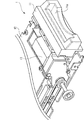
図1は、本発明の実施の形態に係るカードリーダ1の外観を示す斜視図である。また、図2は、図1に示すカードリーダ1の機械構造の概略断面図である。なお、図1と図2とで、構成要素が同じものについては同符号で示す。また、本実施形態では、媒体処理装置の一例としてカードリーダ1を採用したが、例えば銀行カードやチケットなどの情報記録媒体に対し、情報の読み取り又は書き込みを行う媒体処理装置であれば、如何なるものであっても本発明を適用できる。
[Card reader]
FIG. 1 is a perspective view showing an appearance of a card reader 1 according to an embodiment of the present invention. FIG. 2 is a schematic cross-sectional view of the mechanical structure of the card reader 1 shown in FIG. In FIG. 1 and FIG. 2, the same components are denoted by the same reference numerals. In the present embodiment, the card reader 1 is used as an example of the medium processing apparatus. However, any medium processing apparatus that reads or writes information on an information recording medium such as a bank card or a ticket may be used. Even so, the present invention can be applied.
図1及び図2において、カードリーダ1は、カード(図示せず)に対して種々の情報処理を行う装置本体12に、カードが挿入される挿入口11aを有するベゼル(フロント部材の一例)11が、係合部11c(図2)を介して取り付けられた構成となっている。装置本体12は、駆動ローラ(図示せず)を回転させてカードを搬送するモータ13(図1)と、カード表面上に形成された磁気ストライプに対し磁気データの記録又は再生を行う磁気ヘッド14と、装置本体12のベゼル11側の端部に設けられ、装置本体12へのカードの挿入を阻止するPINシャッタ15と、カード位置を検出するために、発光素子31a,32aと対向して配置された受光素子(フォトセンサ)31b,32bと、その他、様々な機械部品及び電気部品から構成されている。
1 and 2, a card reader 1 includes a bezel (an example of a front member) 11 having an
なお、図2において、装置本体12の奥側とは右側を意味し、挿入口11aから挿入されたカードは、装置本体12の奥側に通じる走行路を走行する。もちろん、カードが排出される際には、装置本体12の奥側(図2右側)から挿入口11a(図2左側)に向かって走行路を走行する。
In FIG. 2, the back side of the apparatus
磁気ヘッド14は、カード表面上に形成された磁気ストライプに接触・摺動することによって、磁気データの記録又は再生を行う。より具体的には、磁気ヘッド14は、磁気ギャップ(ギャップスペーサ)を挟んで対向配置された少なくとも一対の磁気コアからなり、一方の磁気コアには再生用コイル、他方の磁気コアには記録用コイルが巻かれ、挿入カードに対してヘッド部が所定のパッド圧で摺接して相対的に移動する。これより、カードに格納された磁気データを読み取ったり(情報の読み取り)、カードに対して新たな磁気データを書き込んだり(情報の書き込み)することが可能となる。なお、磁気ヘッド14は、そのギャップ形成面がカード搬送路内に突出するように配置されている。
The
図3は、PINシャッタ15の機械動作を説明するための断面図である。なお、図3では、装置本体12からベゼル11を取り外し、PINシャッタ15を見え易くしている。
FIG. 3 is a cross-sectional view for explaining the mechanical operation of the
図3(a)において、PINシャッタ15は、略L字形状をしており、支軸17を中心に回転可能となっている。また、PINシャッタ15には、略L字形状の空洞が形成されており、そこには、ソレノイド16のプランジャに形成された突起部16aが位置するようになっている。従って、図3(a)の状態から、ソレノイド16を作動させ、突起部16aをソレノイド16側に引いたとき(突起部16aが左方へ移動したとき)、PINシャッタ15は、支軸17を中心に右回りに回転し、その結果、PINシャッタ15の先端部15aが走行路に対して進出するようになる(図3(b)参照)。なお、PINシャッタ15が左回りに回転すると、PINシャッタ15の先端部15aが走行路に対して後退するようになる。また、本実施形態ではPINシャッタ15を用いることとしたが、例えばギロチンシャッタや可倒式シャッタなど、他の種類のシャッタを用いても構わない。
In FIG. 3A, the
受光素子31b,32bは、CPU等から構成される情報処理ユニット(図示せず)と電気的に接続されており、発光素子31a,32aと協同してカード位置を検出する。受光素子31b,32bは、例えば、フォトダイオード,赤外線受光素子,紫外線受光素子,光導電素子など、その種類の如何は問わない。
The
以上のような構成からなるカードリーダ1において、カードに対する情報の読み取り又は書き込みの流れを説明すると、まず、PINシャッタ15は閉状態となっている。これにより、カードや異物の誤挿入を防止することができる。次に、PINシャッタ15が閉状態から開状態に遷移し、カードが挿入口11aに挿入されると、発光素子31aから出射された光が遮られるため、受光素子31bの受光量が減少する。この受光量減少を検出することによって、カードリーダ1はカードが挿入されたことを認識し、モータ13を回転駆動させる。そうすると、駆動ローラ(図示せず)が回転し、カードの引き込みが行われる(搬送)。そして、走行路内を走行中のカードは、途中、走行路内に突出された磁気ヘッド14のギャップ形成面と摺動し、内部に格納された磁気データが読み取られたり、内部に新たに磁気データが書き込まれたりする。このとき、受光素子32bの受光量変化に基づいてカード位置を正確に検出しつつ、的確な磁気データのやり取りが行われる。
In the card reader 1 configured as described above, the flow of reading or writing information on the card will be described. First, the
最後に、カードに対する情報処理が終了すると、モータ13が逆回転し、カードは、走行路をベゼル11側に向けて走行し、挿入口11aを介して外部へ排出されることになる。なお、本実施形態では、磁気データの読み取り又は書き込みのみを考えたが、ICカードであれば、専用のIC接点がカードリーダ1に組み込まれ、電子データの読み取り又は書き込みが行われる。また、非接触通信カードであれば、専用の非接触通信アンテナがカードリーダ1に組み込まれ、無線通信データの読み取り又は書き込みが行われる。
Finally, when the information processing for the card is completed, the
ここで、図2に示すように、本実施形態に係るカードリーダ1には、ベゼル11と、装置本体12との間に、防塵シート(防塵部材の一例)18が配設されている。防塵シート18は、走行路を塞ぐことを主目的としている。防塵シート18の構造等について、図4〜図6を用いて詳述する。
Here, as shown in FIG. 2, a dustproof sheet (an example of a dustproof member) 18 is disposed between the
[防塵部材]
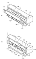
図4は、図1に示すカードリーダ1から、ベゼル11と防塵シート18を取り外したときの様子を示す図である。また、図5は、図4に示すベゼル11を背面側(装置本体12側)から見たときの様子を示す図である。
[Dust-proof material]
FIG. 4 is a diagram illustrating a state when the
図4において、防塵シート18は、一端18aが取り付け板(取り付け部材の一例)19に固定されている。特に、本実施形態では、この一端18aがコの字状に折り曲げられた状態で取り付け板19に固定されている(図5(a)参照)。そして、取り付け板19は、ベゼル11の装置本体12側に着脱自在に取り付けられるようになっている。具体的に説明すると、図5(a)に示すように、ベゼル11の装置本体12側には凹部11bが形成されており、この凹部11bに、取り付け板19の両端部が当接するようになっている。また、図5に示すように、取り付け板19の両端部には、嵌合穴19aが形成されており、この嵌合穴19aと、ベゼル11の装置本体12側に形成された突起部11eとが嵌合するようになっている(図5(a)→図5(b))。なお、取り付け板19は、木製,金属製,樹脂製,アルミ製など、如何なる材質のものであってもよい。
In FIG. 4, one
図4において、防塵シート18は、一端18aと、他端18bとから構成されている。この他端18bは、スリットを有しており、走行路に望む自由端となっている。そして、挿入口11aから挿入されたカードの表面に接触可能に設けられている。なお、他端18bに設けられたスリットは、カードリーダ1に挿入されたカードの厚さ方向における切れ込みであって、取り付け板19の長手方向に複数本設けられている。また、防塵シート18は、不織布,ビニールなど、如何なる材質のものであってもよいが、帯電防止材からなるものにするのが好ましい(或いは、除電シートや除電ブラシなどであってもよい)。これにより、カードに帯電した静電気を逃がすことができる。そして、帯電防止材からなる防塵シートを接地することによって、更に効率的に、静電気を逃がすことができる。また、本実施形態では、防塵シート18を挿入されるカードと接触可能なものとしているが、カードと非接触なものであっても構わない。例えば、カードにある程度近接させておくことで、塵埃が進入するのを防ぐことができるとともに、カードが挿入されることに起因する気流の変化等により、カードに付着した塵埃を除去することができる場合がある。
In FIG. 4, the
図5(b)において、走行路のうち、防塵シート18の自由端(他端18b)と凡そ対峙する位置の少なくとも一部には、切り欠き部20が形成されている。その結果、ベゼル11には、非切り欠き部11dが歯状に形成されている。切り欠き部20と非切り欠き部11dとの面積を比べると、切り欠き部20の方が、非切り欠き部11dよりも小さいものとなっている。ただし、切り欠き部20の面積は、カードが引っ掛からない程度であれば、非切り欠き部21の面積と同等であっても構わない。
In FIG. 5B, a
一方、図5(a)に示すように、ベゼル11には係合部11cが形成されており、この係合部11cが装置本体12と係合することによって、装置本体12に対して着脱自在に設けられる。そして、ベゼル11の係合部11cが装置本体12と係合したとき、取り付け板19は、ベゼル11の凹部11bと装置本体12によって固定されることになる。なお、図1では、ベゼル11は装置本体12に完全に係合しておらず、また、取り付け板19は省略されている。
[実施形態の効果]
On the other hand, as shown in FIG. 5A, the
[Effect of the embodiment]
以上説明したように、本実施形態に係るカードリーダ1によれば、PINシャッタ15により、カードや異物の誤挿入を防止することができ、また、防塵シート18により、PINシャッタ15では阻止できない塵埃などの異物の進入を防ぐことができる。また、防塵シート18により、挿入口11aを介して、装置本体12の奥側を覗き難くすることができるので、セキュリティ性を高めることができる。特に、上述したように、防塵シート18が固定された取り付け板19は、ベゼル11の装置本体12側に着脱自在に取り付けられるようになっている。従って、防塵シート18が悪戯によって剥がされるのを防ぐことができるし、また、ベゼル11を取り外すことによって、防塵シート18の交換や保守点検をワンタッチで容易にすることができる。また、防塵シート18を外部から見え難くすることによって、筐体をデザインする際の自由度を高めることができる。
As described above, according to the card reader 1 of the present embodiment, the
また、防塵シート18のうち、カードと接触するのは柔軟な自由端(他端18b)であることから、カードに傷が付くのを防ぐことができる。また、図5(b)に示すように、挿入口11a付近の走行路には、防塵シート18と凡そ対峙する位置の全幅のうち、少なくとも一部に切り欠き部20が設けられているので、防塵シート18によって進入を防がれた塵埃は、この切り欠き部20の下方に溜まることになる結果、塵埃を容易に除去することができる。特に、切り欠き部20と非切り欠き部11dの面積を比べると、切り欠き部20の方が小さい。これにより、カードが切り欠き20に引っ掛かる確率を小さく(或いはゼロ)にすることができる。
Moreover, since it is a flexible free end (
さらにまた、本実施形に係るカードリーダ1では、上述したように、防塵シート18の他端18bにスリットが入っている。従って、カードに凹凸がある場合であっても(例えばエンボスカードである場合であっても)、カードに付着した塵埃や水滴をより確実に除去することができる。具体的には、図6を用いて詳述する。
Furthermore, in the card reader 1 according to the present embodiment, as described above, the
図6は、凹凸を有するカード100が防塵シート18と接触している様子を示す図である。なお、図6では、カード100と防塵シート18に着目し、他の部品等については省略している。
FIG. 6 is a diagram illustrating a state where the
図6(a)に示すように、カード100には、凸部101が形成されている。そして、このようなカード100が防塵シート18と略対峙する位置に差し掛かったとき、防塵シート18の他端18bのうちの一部が、凸部101の形状に沿って大きく湾曲するようになる(図6(b)参照)。このように、防塵シート18の自由端(他端18b)が図6(b)に示すような動きをすることによって、たとえカードに凹凸がある場合であっても、カードに付着した塵埃や水滴をより確実に除去することができる。また、カード挿抜時に、カードに付着した汚れが防塵シート18に転写することになるので、例えば、ICカードの場合にあってはIC端子のクリーニングになるなど、セルフクリーニング効果を期待することができる。
As shown in FIG. 6A, the
[変形例]
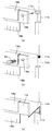
図7は、カードリーダ1の変形例を説明するための説明図である。
[Modification]
FIG. 7 is an explanatory diagram for explaining a modification of the card reader 1.
図7(a)に示すように、上述した本実施形態に係るカードリーダ1では、防塵シート18(及び取り付け板19)が、ベゼル11と、PINシャッタ15を有する装置本体12との間に、直接挟まれるような構成となっている。しかし、例えば図7(b)に示すように、防塵シート18とベゼル11との間に、何らかの部材(例えば接着剤や除電シートなど)22が介在してもよいし、防塵シート18と装置本体12との間にも、何らかの部材21が介在してもよい。例えば、除電シートを間に介在させる場合、除電機能を確保するため、防塵シート18よりも長さが長くなるようにするのがよい。また、何らかの部材21としてコシが強い材質を採用すると、カードを傷付けたり、カード挿入の阻害を招いたりする虞がある。従って、防塵シート18と比べてコシが弱い材質のものを採用するのがよい。
As shown in FIG. 7A, in the card reader 1 according to this embodiment described above, the dustproof sheet 18 (and the mounting plate 19) is between the
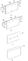
図8は、防塵シート18の変形例を説明するための説明図である。
FIG. 8 is an explanatory diagram for explaining a modified example of the
上述した本実施形態に係るカードリーダ1では、防塵シート18の他端18bに複数のスリットが入っている。しかし、例えば、図8(a)に示すように、1本のスリットが入っているのみであってもよいし、図8(b)に示すように、スリットが入っていなくてもよい。また、防塵部材としては、スリットを有する防塵シート18に限定されるわけではなく、例えば、図8(c)に示すように、中央に切れ込みを有するものであってもよいし、図8(d)に示すように、上下に二枚のシートを重ねてなるものであってもよい。なお、スリットを有する防塵シート18を使うことによって、小型化及び低コスト化に寄与することができる。
In the card reader 1 according to this embodiment described above, the
図9は、取り付け板19をベゼル11に取り付けるにあたっての変形例を説明するための説明図である。
FIG. 9 is an explanatory diagram for explaining a modification example in attaching the
図9(a)に示すように、上述した本実施形態に係るカードリーダ1では、嵌合穴19aと突起部11eが嵌合することによって、取り付け板19がベゼル11に取り付けられるようになっている。しかし、例えば、図9(b)に示すように、ベゼル11の凹部11bに螺子穴11eを形成し、ボルト50をねじ込むことによって、取り付け板19をベゼル11に固定してもよい。また、図9(c)に示すように、ベゼル11の凹部11bに溝部11fを形成し、取り付け板19を嵌め込むことによって、取り付け板19をベゼル11に固定してもよい。なお、取り付け板19を用いることなく、防塵シート18を直接ベゼル11に取り付けてもよい。
As shown in FIG. 9A, in the card reader 1 according to this embodiment described above, the
上述した本実施形態に係るカードリーダ1では、受光素子31b,32bを、カード位置を検出する手段として用いている。しかし、例えば、走行路の汚れを検知する汚れ検知手段として機能させることも可能である。具体的に説明すると、仮に、何らかの理由で走行路内に塵や埃が進入してしまい、受光素子32bの受光量が減少したとする。このとき、受光素子32bに接続された情報処理ユニット(汚れ検知手段の一例)は、受光量変化を認識し、カード搬送への支障があると判断する。そして、PINシャッタ15を作動させ、そのような支障がある状態でのカード挿入を阻止することができる。これにより、カードリーダ1の信頼性を向上することができる。
In the card reader 1 according to this embodiment described above, the
なお、情報処理ユニットがカード搬送への支障があると判断したとき、カードリーダ1が接続された上位装置に異常検知信号(アラーム信号)が送信されるようにしてもよい。これにより、迅速にメンテナンスマンを派遣することができ、派遣されたメンテナンスマンは、ベゼル11を装置本体12から簡単に取り外し、防塵シート18を新しいものと交換することができる。このように、カードリーダ1の保守性(メンテナンス性)を向上することができる。
Note that when the information processing unit determines that there is an obstacle to card conveyance, an abnormality detection signal (alarm signal) may be transmitted to the host device to which the card reader 1 is connected. Accordingly, a maintenance man can be dispatched quickly, and the dispatched maintenance man can easily remove the
本発明に係る媒体処理装置は、防塵性及びセキュリティ性を備え、カードや異物の誤挿入を防止することができ、かつ、保守点検を容易にすることが可能なものとして有用である。 The medium processing device according to the present invention is useful as a device that has dust resistance and security, can prevent erroneous insertion of a card or a foreign object, and can facilitate maintenance and inspection.
1 カードリーダ
11 ベゼル
12 装置本体
13 モータ
14 磁気ヘッド
15 PINシャッタ
16 ソレノイド
17 支軸
18 防塵シート
19 取り付け板
20 切り欠き部
DESCRIPTION OF SYMBOLS 1
Claims (6)
装置本体に対して着脱自在に設けられ、情報記録媒体が挿入される挿入口を有するフロント部材と、
情報記録媒体が前記挿入口から前記装置本体の奥側に走行する走行路と、
前記装置本体の前記フロント部材側の端部に設けられ、前記走行路に対して進出後退し、前記装置本体内への情報記録媒体の挿入を阻止するピン状の突起物を出し入れ可能としたPINシャッタと、
前記フロント部材と前記PINシャッタとの間に配設され、前記走行路を塞ぐ防塵部材と、を備え、
前記防塵部材は、防塵シートであり、情報記録媒体の厚さ方向の上側の一端が取り付け部材に固定されており、該取り付け部材は、前記フロント部材と前記装置本体との間に着脱自在に取り付けられ、
前記防塵部材の他端は、前記走行路に臨む自由端に、前記情報記録媒体の前記厚さ方向の切れ込みからなるスリットを複数本有するとともに、前記挿入口から挿入された情報記録媒体の表面に接触可能に設けられていることを特徴とする媒体処理装置。 In a medium processing apparatus that reads or writes information on an information recording medium,
A front member provided detachably with respect to the apparatus main body and having an insertion slot into which an information recording medium is inserted;
A road on which the information recording medium travels to the back side of the apparatus main body from the insertion opening,
Provided at an end portion of the front member side of the apparatus main body, it advanced retracted relative to the travel path, and allows out a pin-like projections to prevent the insertion of the information recording medium into the apparatus main body PIN A shutter;
A dust-proof member disposed between the front member and the PIN shutter and blocking the travel path;
The dust-proof member is a dust-proof sheet, and an upper end in the thickness direction of the information recording medium is fixed to a mounting member, and the mounting member is detachably mounted between the front member and the apparatus main body. And
The other end of the dust-proof member has a plurality of slits made of cuts in the thickness direction of the information recording medium at the free end facing the traveling path, and on the surface of the information recording medium inserted from the insertion port. A medium processing apparatus provided so as to be contactable.
Priority Applications (2)
| Application Number | Priority Date | Filing Date | Title |
|---|---|---|---|
| JP2006176095A JP5114766B2 (en) | 2006-06-27 | 2006-06-27 | Media processing device |
| CN2007101279163A CN101097595B (en) | 2006-06-27 | 2007-06-26 | Medium processing apparatus |
Applications Claiming Priority (1)
| Application Number | Priority Date | Filing Date | Title |
|---|---|---|---|
| JP2006176095A JP5114766B2 (en) | 2006-06-27 | 2006-06-27 | Media processing device |
Publications (2)
| Publication Number | Publication Date |
|---|---|
| JP2008009478A JP2008009478A (en) | 2008-01-17 |
| JP5114766B2 true JP5114766B2 (en) | 2013-01-09 |
Family
ID=39011423
Family Applications (1)
| Application Number | Title | Priority Date | Filing Date |
|---|---|---|---|
| JP2006176095A Expired - Fee Related JP5114766B2 (en) | 2006-06-27 | 2006-06-27 | Media processing device |
Country Status (2)
| Country | Link |
|---|---|
| JP (1) | JP5114766B2 (en) |
| CN (1) | CN101097595B (en) |
Families Citing this family (6)
| Publication number | Priority date | Publication date | Assignee | Title |
|---|---|---|---|---|
| US8820640B2 (en) * | 2008-09-30 | 2014-09-02 | Nidec Sankyo Corporation | Magnetic card reader and magnetic data read method |
| JP2010242907A (en) * | 2009-04-08 | 2010-10-28 | Mitsutoyo Corp | Dust-proofing device for moving mechanism, and measuring instrument |
| JP5917980B2 (en) * | 2012-03-30 | 2016-05-18 | 日本電産サンキョー株式会社 | Information recording medium processing apparatus and signal processing method |
| JP6078457B2 (en) * | 2013-11-08 | 2017-02-08 | 日本電産サンキョー株式会社 | Card reader |
| JP7403791B2 (en) | 2019-09-28 | 2023-12-25 | 三和ニューテック株式会社 | card reader |
| JP7347247B2 (en) | 2020-02-03 | 2023-09-20 | 株式会社デンソー | In-vehicle device |
Family Cites Families (10)
| Publication number | Priority date | Publication date | Assignee | Title |
|---|---|---|---|---|
| JPH0530200Y2 (en) * | 1986-05-30 | 1993-08-02 | ||
| JPH06266958A (en) * | 1993-03-17 | 1994-09-22 | Omron Corp | Automatic check-out system |
| JPH07141851A (en) * | 1993-06-18 | 1995-06-02 | Olympus Optical Co Ltd | Information recording and reproducing device |
| JPH087048A (en) * | 1994-04-22 | 1996-01-12 | Fuji Electric Co Ltd | Card application device |
| JPH0950495A (en) * | 1995-08-10 | 1997-02-18 | Nippon Conlux Co Ltd | Information recording/reproducing device |
| JP2000067149A (en) * | 1998-08-20 | 2000-03-03 | Matsushita Electric Ind Co Ltd | Cleaning device |
| US20040007624A1 (en) * | 2000-06-15 | 2004-01-15 | Hiroshi Ogawa | Medium processing apparatus |
| JP2002150225A (en) * | 2000-11-10 | 2002-05-24 | Matsushita Electric Ind Co Ltd | Memory card device |
| JP2003317045A (en) * | 2002-04-25 | 2003-11-07 | Toshiba Tec Corp | Card processor |
| JP4575032B2 (en) * | 2004-05-31 | 2010-11-04 | 富士通株式会社 | Medium processing apparatus and medium issuing apparatus using the same |
-
2006
- 2006-06-27 JP JP2006176095A patent/JP5114766B2/en not_active Expired - Fee Related
-
2007
- 2007-06-26 CN CN2007101279163A patent/CN101097595B/en not_active Expired - Fee Related
Also Published As
| Publication number | Publication date |
|---|---|
| CN101097595B (en) | 2012-06-06 |
| CN101097595A (en) | 2008-01-02 |
| JP2008009478A (en) | 2008-01-17 |
Similar Documents
| Publication | Publication Date | Title |
|---|---|---|
| JP5114766B2 (en) | Media processing device | |
| US9734363B2 (en) | Card reader | |
| US9552501B2 (en) | Card reader and control method of card reader | |
| US10068112B2 (en) | Card reader | |
| CN110502937B (en) | Card reader | |
| WO2014051074A1 (en) | Card reader | |
| JP5364540B2 (en) | Card-like medium processing apparatus and method for controlling card-like medium processing apparatus | |
| JP2011209981A (en) | Card processing apparatus and card processing system | |
| JP5964191B2 (en) | Card reader | |
| JP7149113B2 (en) | Card reader and foreign object detection method | |
| WO2011001506A1 (en) | Magnetic card reader | |
| US11853999B2 (en) | Card reader and foreign matter detection method therefor | |
| JP2009176078A (en) | Card reader | |
| JP5385812B2 (en) | Card reader | |
| JP5049681B2 (en) | Card reader | |
| JP4815161B2 (en) | Card reader | |
| CN110619246B (en) | Card reader and foreign matter detection method | |
| JP2001067631A (en) | Card reader, method for discriminating card type and method for cleaning card reader | |
| US11710004B2 (en) | Card reader and foreign object detection method for card reader | |
| JP5850568B2 (en) | Card reader | |
| JP4843769B2 (en) | Media processing device | |
| JP2002298098A (en) | Card reader/writer | |
| JPH0713854U (en) | Optical sensor of card reader | |
| JPH07249105A (en) | Magnetic card reader | |
| JPH07249104A (en) | Magnetic card reader |
Legal Events
| Date | Code | Title | Description |
|---|---|---|---|
| A621 | Written request for application examination |
Free format text: JAPANESE INTERMEDIATE CODE: A621 Effective date: 20080827 |
|
| A977 | Report on retrieval |
Free format text: JAPANESE INTERMEDIATE CODE: A971007 Effective date: 20110803 |
|
| A131 | Notification of reasons for refusal |
Free format text: JAPANESE INTERMEDIATE CODE: A131 Effective date: 20110809 |
|
| A521 | Written amendment |
Free format text: JAPANESE INTERMEDIATE CODE: A523 Effective date: 20111006 |
|
| A131 | Notification of reasons for refusal |
Free format text: JAPANESE INTERMEDIATE CODE: A131 Effective date: 20120207 |
|
| A521 | Written amendment |
Free format text: JAPANESE INTERMEDIATE CODE: A523 Effective date: 20120406 |
|
| TRDD | Decision of grant or rejection written | ||
| A01 | Written decision to grant a patent or to grant a registration (utility model) |
Free format text: JAPANESE INTERMEDIATE CODE: A01 Effective date: 20120911 |
|
| A01 | Written decision to grant a patent or to grant a registration (utility model) |
Free format text: JAPANESE INTERMEDIATE CODE: A01 |
|
| A61 | First payment of annual fees (during grant procedure) |
Free format text: JAPANESE INTERMEDIATE CODE: A61 Effective date: 20120925 |
|
| R150 | Certificate of patent or registration of utility model |
Free format text: JAPANESE INTERMEDIATE CODE: R150 |
|
| FPAY | Renewal fee payment (event date is renewal date of database) |
Free format text: PAYMENT UNTIL: 20151026 Year of fee payment: 3 |
|
| LAPS | Cancellation because of no payment of annual fees |