JP5114037B2 - Coating apparatus and coating method - Google Patents
Coating apparatus and coating method Download PDFInfo
- Publication number
- JP5114037B2 JP5114037B2 JP2006261381A JP2006261381A JP5114037B2 JP 5114037 B2 JP5114037 B2 JP 5114037B2 JP 2006261381 A JP2006261381 A JP 2006261381A JP 2006261381 A JP2006261381 A JP 2006261381A JP 5114037 B2 JP5114037 B2 JP 5114037B2
- Authority
- JP
- Japan
- Prior art keywords
- coating
- gantry
- web
- die
- coating apparatus
- Prior art date
- Legal status (The legal status is an assumption and is not a legal conclusion. Google has not performed a legal analysis and makes no representation as to the accuracy of the status listed.)
- Active
Links
Images


Classifications
-
- B—PERFORMING OPERATIONS; TRANSPORTING
- B05—SPRAYING OR ATOMISING IN GENERAL; APPLYING FLUENT MATERIALS TO SURFACES, IN GENERAL
- B05C—APPARATUS FOR APPLYING FLUENT MATERIALS TO SURFACES, IN GENERAL
- B05C5/00—Apparatus in which liquid or other fluent material is projected, poured or allowed to flow on to the surface of the work
- B05C5/02—Apparatus in which liquid or other fluent material is projected, poured or allowed to flow on to the surface of the work the liquid or other fluent material being discharged through an outlet orifice by pressure, e.g. from an outlet device in contact or almost in contact, with the work
- B05C5/0254—Coating heads with slot-shaped outlet
- B05C5/0262—Coating heads with slot-shaped outlet adjustable in width, i.e. having lips movable relative to each other in order to modify the slot width, e.g. to close it
-
- B—PERFORMING OPERATIONS; TRANSPORTING
- B05—SPRAYING OR ATOMISING IN GENERAL; APPLYING FLUENT MATERIALS TO SURFACES, IN GENERAL
- B05C—APPARATUS FOR APPLYING FLUENT MATERIALS TO SURFACES, IN GENERAL
- B05C5/00—Apparatus in which liquid or other fluent material is projected, poured or allowed to flow on to the surface of the work
- B05C5/02—Apparatus in which liquid or other fluent material is projected, poured or allowed to flow on to the surface of the work the liquid or other fluent material being discharged through an outlet orifice by pressure, e.g. from an outlet device in contact or almost in contact, with the work
- B05C5/0254—Coating heads with slot-shaped outlet
-
- B—PERFORMING OPERATIONS; TRANSPORTING
- B05—SPRAYING OR ATOMISING IN GENERAL; APPLYING FLUENT MATERIALS TO SURFACES, IN GENERAL
- B05D—PROCESSES FOR APPLYING FLUENT MATERIALS TO SURFACES, IN GENERAL
- B05D1/00—Processes for applying liquids or other fluent materials
- B05D1/26—Processes for applying liquids or other fluent materials performed by applying the liquid or other fluent material from an outlet device in contact with, or almost in contact with, the surface
-
- B—PERFORMING OPERATIONS; TRANSPORTING
- B05—SPRAYING OR ATOMISING IN GENERAL; APPLYING FLUENT MATERIALS TO SURFACES, IN GENERAL
- B05C—APPARATUS FOR APPLYING FLUENT MATERIALS TO SURFACES, IN GENERAL
- B05C5/00—Apparatus in which liquid or other fluent material is projected, poured or allowed to flow on to the surface of the work
- B05C5/02—Apparatus in which liquid or other fluent material is projected, poured or allowed to flow on to the surface of the work the liquid or other fluent material being discharged through an outlet orifice by pressure, e.g. from an outlet device in contact or almost in contact, with the work
- B05C5/0245—Apparatus in which liquid or other fluent material is projected, poured or allowed to flow on to the surface of the work the liquid or other fluent material being discharged through an outlet orifice by pressure, e.g. from an outlet device in contact or almost in contact, with the work for applying liquid or other fluent material to a moving work of indefinite length, e.g. to a moving web
Description
本発明は、塗布装置及び塗布方法に関するものであり、特に、写真感光乳化剤、磁性液、視野角向上膜、反射防止膜を形成するための溶液、カラーフィルター用顔料液、表面保護膜を形成するための溶液等の塗布液をプラスチックフィルム、紙、金属箔等の支持体に塗布するための塗布装置及び塗布方法に関するものである。 The present invention relates to a coating apparatus and a coating method, and in particular, forms a photographic photosensitive emulsifier, a magnetic liquid, a viewing angle improving film, a solution for forming an antireflection film, a pigment liquid for a color filter, and a surface protective film. The present invention relates to a coating apparatus and a coating method for coating a coating solution such as a solution for a coating on a support such as a plastic film, paper, or metal foil.
移動する支持体(ウエブ等)の表面に塗布液を塗布するための方法として、ダイコーティング法が知られている。近年は、ダイコーティング法により形成される膜の高性能化等に伴い、従来よりも薄い潤滑膜厚が20〔μm〕以下の領域で、高精度な積層膜を形成する技術が要求されている。このような薄い膜を均一に形成するためには、塗布装置における精度、特に、先端リップとウエブとのクリアランスが非常に重要となる。 A die coating method is known as a method for applying a coating solution to the surface of a moving support (such as a web). In recent years, with the improvement of the performance of a film formed by a die coating method, a technique for forming a highly accurate laminated film in a region where the lubricant film thickness is thinner than 20 μm is required. . In order to form such a thin film uniformly, accuracy in the coating apparatus, in particular, the clearance between the tip lip and the web is very important.
このクリアランスは、環境温度のみならず塗布装置の製造における影響を強く受けるものであり、塗布されるウエブ幅全体にわたり均一にする必要があることから、最終的には微調整を行う必要がある。特許文献1及び特許文献2には、塗布ダイと塗布ダイを固定する架台とを複数の押しボルト、引きボルトで連結し、これらの押しボルト、引きボルトを調整することにより、先端リップとウエブとのクリアランスを調整する方法が開示されている。
しかしながら、特許文献1及び特許文献2に開示されている発明は、先端リップとウエブとのクリアランスの調整は可能であるが、押しボルト及び引きボルトのボルトによる調整であることから、一般にボルトは遊び等を有しているため正確な位置に調整を行うことが困難であり、調整の再現性が乏しいため、偶発的な成功になるまでボルトによる調整を繰り返すことになる。また、このようなボルトによる調整では、塗布装置における回転体等の振動を受け、塗布を行っている途中でボルトがゆるみ、クリアランスが変化してしまい塗布液を均一に塗布できないといった問題や、ウエブを破損するといった問題などの実用上の問題が多い。 However, in the inventions disclosed in Patent Document 1 and Patent Document 2, the clearance between the tip lip and the web can be adjusted. However, since the adjustment is made by the push bolt and the pull bolt, the bolt is generally free of play. Therefore, it is difficult to make an adjustment at an accurate position, and the reproducibility of the adjustment is poor. Therefore, the adjustment by the bolt is repeated until accidental success. In addition, such adjustment using a bolt causes problems such as a problem that the bolt is loosened during application and the clearance changes during application while the application liquid is not uniformly applied. There are many practical problems such as the problem of damaging.
本発明は、上記事情に鑑みてなされたものであり、クリアランスの位置調整を容易に行うことができ、かつ、塗布工程におけるクリアランスの変化が少ない塗布装置及び塗布方法を提供するものである。 The present invention has been made in view of the above circumstances, and provides a coating apparatus and a coating method capable of easily adjusting the position of the clearance and having little change in the clearance in the coating process.
請求項1に記載の発明は、移動しているウエブ上に、架台に固定された塗布ダイの先端リップから塗布液を塗布する塗布装置において、前記塗布ダイと接合される架台の接合面の接合領域に、前記塗布ダイと前記架台とを結合するためのボルトを貫通させるための穴または切欠きを有するシムを複数配置し、配置された前記シムの各々の厚さを調整することにより、塗布ダイの先端リップにおける真直度を調整することを特徴とする塗布装置である。 The invention according to claim 1 is a coating apparatus for applying a coating liquid from a tip lip of a coating die fixed to a gantry on a moving web, and joining a joint surface of the gantry to be joined to the coating die. In the region, a plurality of shims having holes or notches for penetrating bolts for connecting the coating die and the gantry are disposed, and the thickness of each of the disposed shims is adjusted, thereby coating A coating apparatus that adjusts the straightness of a tip lip of a die.
請求項2に記載の発明は、前記接合領域は、前記架台の接合面において塗布ダイの方向に凸となっていることを特徴とする請求項1に記載の塗布装置である。 The invention according to claim 2 is the coating apparatus according to claim 1, wherein the joining region is convex in the direction of the coating die on the joining surface of the gantry.
請求項3に記載の発明は、前記シムは、ウエブの移動方向に垂直な方向における幅が、前記ボルト直径の1.2倍〜7倍であることを特徴とする請求項1または2に記載の塗布装置である。
The invention according to
請求項4に記載の発明は、前記架台の接合面に配置されるシムが、4個以上であり、かつ使用される前記シムのウエブ移動方向に垂直な方向における幅の合計が、前記架台の接合面のウエブ移動方向に垂直な方向における幅方向の合計の半分以下であることを特徴とする請求項1から3のいずれかに記載の塗布装置である。
In the invention according to
請求項5に記載の発明は、前記架台は、塗布ダイから前記架台を固定する固定台に向かう方向に形成されている複数の柱が存在しており、前記接合領域はすべて前記柱の端上となる領域に形成されていることを特徴とする請求項1から4のいずれかに記載の塗布装置である。
In the invention according to
請求項6に記載の発明は、前記柱の他方の端となる領域における面のすべて、又は、両端を除くすべての面が、前記固定台と密着していることを特徴とする請求項5に記載の塗布装置である。
Invention according to
請求項7に記載の発明は、前記シムは、SUS鋼により構成されていることを特徴とする請求項1から6のいずれかに記載の塗布装置である。 A seventh aspect of the present invention is the coating apparatus according to any one of the first to sixth aspects, wherein the shim is made of SUS steel.
請求項8に記載の発明は、前記塗布ダイの先端リップに近接して配置されたウエブを巻きつけたバックアップローラを回転させ、前記バックアップローラの回転により移動している前記ウエブ上に、請求項1から7のいずれかに記載の塗布装置の先端リップより塗布液を供給することを特徴とする塗布方法である。 According to an eighth aspect of the present invention, the backup roller around which the web disposed close to the tip lip of the coating die is rotated, and the web is moved by the rotation of the backup roller. 8. A coating method, wherein a coating liquid is supplied from a tip lip of the coating apparatus according to any one of 1 to 7.
以上より、本発明における塗布装置及び塗布方法によれば、クリアランスの調整が容易に行うことができ、また、塗布工程におけるクリアランスの変化が少ないため、ウエブ上に安定的に均一に塗布液を塗布することができる。 As described above, according to the coating apparatus and the coating method of the present invention, the clearance can be easily adjusted, and since the change in the clearance in the coating process is small, the coating liquid can be stably and uniformly applied on the web. can do.
〔塗布装置〕
本発明に係る塗布装置の実施の形態を図1に基づき説明する。
[Coating equipment]
An embodiment of a coating apparatus according to the present invention will be described with reference to FIG.
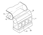
図1は、本実施の形態における塗布装置のウエブ幅方向に垂直に切断した断面図であり、図2は、本実施の形態における塗布装置の斜視図である。 FIG. 1 is a cross-sectional view cut perpendicularly to the web width direction of the coating apparatus in the present embodiment, and FIG. 2 is a perspective view of the coating apparatus in the present embodiment.
本実施の形態における塗布装置は、バックアップローラ14に連続走行するウエブ15が巻きつけられており、塗布ダイ12は、このバックアップローラ14に近接して配置され、塗布ダイ12からは塗布液16がウエブ15上に塗布される構成になっている。
In the coating apparatus according to the present embodiment, a
塗布ダイ12は、直接、もしくはSUS鋼により構成されているシム13を介し架台11と接合されている。シム13の中央には、塗布ダイ12を架台11に固定するための穴または切欠きが形成され、塗布ダイ12には、架台11を固定するためのねじ穴が形成されている。塗布ダイ12は、この穴または切欠きを介しボルト22によって、架台11に固定されている。更に、架台11は、固定台23に固定されている。尚、本実施の形態では、SUS鋼からなるシム13を用いたが、経時変化の少ない材料であって、剛性の高い材料であれば、特に限定されるものではない。
The
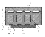
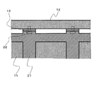
塗布液16をウエブ15に均一に塗布するためには、前述のとおり、バックアップローラ14と塗布ダイ12の先端リップ12aとの間隔、即ち、クリアランスが均一であることが望ましい。このため複数のシム13を架台11と塗布ダイ12の間に挿入し、各々の挿入されるシム13の厚さを変えることにより塗布ダイ12の先端リップ12aの先端の真直度を調整し、バックアップローラ14と塗布ダイ12の先端リップ12aとの間隔が均一になるように調整するものである。具体的に図3、図4に基づき説明する。図3は、本実施の形態における塗布装置のウエブ幅方向に平行に切断した断面図であり、図4はこの拡大図である。図3に示すように、塗布ダイ12と架台11とは複数のシム13を介し接合されている。塗布ダイ12の先端リップ12aの真直度を調整するためには、各々のシム13の膜厚の異なるものを挿入することにより調整を行う。各々のシム13の設置される位置は、架台11に設けられている強度確保のための柱21の塗布ダイ12側の端面に相当する位置である。具体的には、架台11を固定するための固定台23と塗布ダイ12との間に設けられた架台11の強度確保のための柱21の塗布ダイ12側の端面において、その柱21の端の領域のみ接触の再現性を上げるための凸面が形成されており、この領域に、シム13を介し架台11に塗布ダイ12を固定した構成のものである。架台11の柱21の端上において、塗布ダイ12が固定されているため、塗布ダイ12の重量等により架台11が変形することはなく、塗布ダイ12の先端リップ12aの真直度を安定的に高めることができるものである。
In order to uniformly apply the
一方、図3に示すように、架台11の柱21の他方の端の面は、両端の柱21を除き固定台23の表面と接触し接触面25となっているため、塗布ダイ12の重量等の及ぼす力はすべて、架台11の柱21を介し、固定台23の表面にかかる。従って、塗布ダイ12の加重による架台11の変形は極めて少なく、固定台23を変形しない材料で構成することにより、塗布ダイ12の先端リップ12aの真直度は変化することがない。本実施の形態では、振動等による移動を防止するため架台11と固定台23とは4本のボルトにより固定されている。尚、架台11の柱21の他方の端の面のすべての面を固定台23に表面と接触させてもよい。
On the other hand, as shown in FIG. 3, the surface of the other end of the
以上の構成とすることにより、シム13による調整を一旦行えば、長期間そのままの状態で使用することが可能である。
With the above configuration, once adjustment by the
発明者らの検討の結果では、架台11の柱21の塗布ダイ12の幅方向の幅(ウエブ幅方向の幅)は、ボルト呼び径の1.4倍以上であり、かつ20〔mm〕以上、100〔mm〕以下であることが望ましい。架台11が変形しないためには、ボルト呼び径の1.4倍以上かつ20〔mm〕以上の幅が必要であるからである。尚、架台11に柱21を形成することなく、架台11の全体をバルク状に形成した場合では、架台11の重量は非常に重いものとなり、移動や微調整等を行う際に困難になるとともに、架台11自身の自重により変形する場合があるため、構造としては適当とはいいがたい。従って、柱の幅は、100〔mm〕以下であることが望ましい。
As a result of the study by the inventors, the width in the width direction of the
更に、この柱21の塗布ダイ12側の端の面にシム13を配置し塗布ダイ12の先端リップ12aの真直度の調整を行うため、設置されるシム13の数は4個以上必要となる。シムの数が3個以下では、シムによる先端リップ12aの真直度の微妙な調整を行うことができないからである。
Furthermore, in order to adjust the straightness of the
また、通常は架台11には切欠き26が設けられるが、架台11の柱21は、塗布ダイ12より固定台23まで貫く構造で支えているため、柱21の端の接触面25以外の面に形成される構成が望ましい。尚、このような切欠き26が形成されない架台11の構造もあり、この場合は、固定台23と架台11は広い領域において接触面25を形成することとなる。
In addition, although the
〔塗布方法〕
次に、図1に基づき、本発明に係る塗布方法について説明する。本発明に係る塗布方法は、前述した本発明に係る塗布装置を用いる。具体的には、塗布ダイ12に供給された塗布液16は、塗布ダイ12内に形成されたスリットを介し、塗布ダイ12の先端リップ12aに供給される。塗布ダイ12の先端リップ12aは、バックアップローラ14により、連続走行しているウエブ15に近接して所定のクリアランスで配置されており、塗布液16は塗布ダイ12の先端リップ12aとウエブ15の間において、一種のビードを形成しながら、ウエブ15に塗布される。塗布される際のクリアランスは、ウエブ15の幅全体にわたり、3〔μm〕以下であることが望ましく、この範囲内に収まるようにシム13により塗布ダイ12の先端リップ12aの真直度が調整されている。
[Coating method]
Next, the coating method according to the present invention will be described with reference to FIG. The coating method according to the present invention uses the above-described coating apparatus according to the present invention. Specifically, the
尚、塗布される塗布液16の粘度は、0.1〜1000〔p〕(0.01〜100〔Pa・s〕)の範囲が好ましく、より好ましくは、1〜100〔P〕(0.1〜10〔Pa・s〕)が好ましい。
In addition, the range of 0.1-1000 [p] (0.01-100 [Pa * s]) is preferable, and, as for the viscosity of the
塗布液16の塗布されたウエブ15は、乾燥処理、カレンダー処理が施された後、一旦ロール状に巻き取られ、ロール状のまま加熱又はUV照射により硬化処理される。硬化処理されたウエブ15は、所定の幅に細長く裁断されて写真感光材料や磁気記録媒体、PS版、光学機能性フィルム等の製品となる。
The
尚、本発明に係る塗布装置及び塗布方法により、液晶、磁性材料、写真感光剤、有機EL、色素材料、粘着材料、導電性材料、絶縁性材料等を塗布することができる。 In addition, liquid crystal, a magnetic material, a photographic photosensitive agent, an organic EL, a dye material, an adhesive material, a conductive material, an insulating material, and the like can be applied by the coating apparatus and the coating method according to the present invention.
以上、本発明に係る塗布装置及び塗布方法について詳細に説明したが、本発明は、以上の例には限定されず、本発明の要旨を逸脱しない範囲において、各種の改良や変形を行うことが可能である。 As described above, the coating apparatus and the coating method according to the present invention have been described in detail. However, the present invention is not limited to the above examples, and various improvements and modifications can be made without departing from the gist of the present invention. Is possible.
次に、本発明の実施例と比較例とを対比した試験結果を説明する。 Next, test results comparing the examples of the present invention and comparative examples will be described.
(1)実施例の塗布ダイ及び架台の条件を次のようにした。 (1) The conditions of the coating die and the gantry of the example were as follows.
(塗布ダイ)
塗布ダイとして全長1400mm、有効塗布幅1250mmのダイを用いた。
(Coating die)
As the coating die, a die having a total length of 1400 mm and an effective coating width of 1250 mm was used.
(架台)
架台として全長1200mmのものを使用し、止めボルトの呼び径及び本数、柱の数および本数、等を変更した架台を作成し、塗布ダイを搭載、リップ先端の真直度を測定した。
(Frame)
A base having a total length of 1200 mm was used as a base, and a base with a changed nominal diameter and number of retaining bolts, number of columns and number, etc. was prepared, a coating die was mounted, and the straightness of the lip tip was measured.
(2)一方、比較例の塗布ダイ及び架台の条件を次のようにした。 (2) On the other hand, the conditions of the coating die and the gantry of the comparative example were as follows.
(塗布ダイ)
実施例と同様に、塗布ダイとして全長1400mm、有効塗布幅1250mmのダイを用いた。
(Coating die)
As in the example, a die having a total length of 1400 mm and an effective coating width of 1250 mm was used as the coating die.
(架台)
架台として実施例と同様の架台を作成した。ただし塗布ダイの固定および真直度
調整はシムを用いずに、押し引きボルトによって行なう構造とした。
(Frame)
A gantry similar to the example was created as a gantry. However, the application die was fixed and the straightness was adjusted using a push-pull bolt without using a shim.
(3)真直度の測定等は次のように実施した。 (3) The straightness was measured as follows.
〔真直度の測定〕
真直度は塗布ダイをバックアップロールに正対させ、ダイリップ先端とバックアップロールの間隔をシックネスゲージにより測定し、該間隔の最大値−最小値により求めた。
(Measurement of straightness)
The straightness was determined by measuring the distance between the die lip tip and the backup roll with a thickness gauge with the coating die facing the backup roll, and calculating the maximum-minimum value of the distance.
〔リニアリティ〕
シム又は押し引きボルトの調整量に対するリップ先端の移動量の比率をリニアリティとして定義した。例えば、シムA、Bの厚みをtA、tB、そのときのリップ先端の初期値に対する移動量をdA、dBとしたとき、リニアリティ=(dB−dA)/(tB−tA)×100(%)で定義される。
[Linearity]
The ratio of the amount of movement of the lip tip to the amount of adjustment of the shim or push-pull bolt was defined as linearity. For example, when the thicknesses of the shims A and B are tA and tB, and the movement amounts with respect to the initial value of the lip tip at that time are dA and dB, linearity = (dB−dA) / (tB−tA) × 100 (%) Defined by
〔試験結果〕
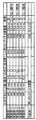
上記の実施例と比較例との試験結果を表図1に示した。評価は、リニアリティと真直度の両方が良い結果のものを◎、リニアリティと真直度の何れかが良い場合を△○、または○とし、両方とも悪い結果の場合を×とした。
〔Test results〕
The test results of the above examples and comparative examples are shown in FIG. In the evaluation, ◎ indicates that both linearity and straightness are good, △ indicates that either linearity or straightness is good, and ○ indicates that both are bad.
表図1から分かるように、シムによって真直度を調整した本発明の実施例1〜6は、リニアリティが65%以上で、ダイリップ先端とバックアップロールの間隔が最大でも5.2μmであり、良好なリニアリティ及び真直度を得ることができた。実施例1〜6のなかでも特に、シムのウエブの移動方向に垂直な方向における幅が、ボルト直径の1.2倍〜7倍(図表1の「倍率」)で、かつ架台の柱本数が4本以上である条件を満足する実施例1、3、5は◎で良い結果であった。 As can be seen from FIG. 1, Examples 1 to 6 of the present invention in which the straightness is adjusted by shims have a linearity of 65% or more and a maximum distance between the die lip tip and the backup roll of 5.2 μm, which is good. Linearity and straightness could be obtained. Especially in Examples 1 to 6, the width in the direction perpendicular to the moving direction of the shim web is 1.2 to 7 times the bolt diameter (“Magnification” in Chart 1), and the number of columns of the gantry is Examples 1, 3, and 5 satisfying the condition of 4 or more were good results with ◎.
これに対して、押しボルトによって真直度を調整した比較例の場合には、リニアリティが55%と実施例6よりも小さく、ダイリップ先端とバックアップロールの間隔が12.0μmと大きく、リニアリティ及び真直度ともに悪い結果であった。 On the other hand, in the case of the comparative example in which the straightness is adjusted by the push bolt, the linearity is 55%, which is smaller than that of Example 6, the distance between the die lip tip and the backup roll is as large as 12.0 μm, and the linearity and the straightness. Both were bad results.
11…架台、12…塗布ダイ、12a…先端リップ、13…シム、14…バックアップローラ、15…ウエブ、16…塗布液、21…柱、22…ボルト、23…固定台、25…接触面、26…切欠き
DESCRIPTION OF
Claims (8)
前記塗布ダイと接合される架台の接合面の接合領域に、前記塗布ダイと前記架台とを結合するためのボルトを貫通させるための穴または切欠きを有するシムを複数配置し、
配置された前記シムの各々の厚さを調整することにより、塗布ダイの先端リップにおける真直度を調整することを特徴とする塗布装置。 In a coating apparatus that applies a coating liquid from the tip lip of a coating die fixed to a gantry on a moving web,
A plurality of shims having holes or notches for penetrating bolts for connecting the coating die and the gantry are disposed in the joining region of the joining surface of the gantry to be joined to the coating die,
The coating apparatus characterized by adjusting the straightness of the tip lip of the coating die by adjusting the thickness of each of the arranged shims.
前記バックアップローラの回転により移動している前記ウエブ上に、請求項1から7のいずれかに記載の塗布装置の先端リップより塗布液を供給することを特徴とする塗布方法。 Rotating a backup roller around which a web arranged close to the tip lip of the coating die is wound,
A coating method, comprising: supplying a coating liquid from a tip lip of a coating apparatus according to any one of claims 1 to 7 onto the web that is moved by the rotation of the backup roller.
Priority Applications (5)
| Application Number | Priority Date | Filing Date | Title |
|---|---|---|---|
| JP2006261381A JP5114037B2 (en) | 2006-09-26 | 2006-09-26 | Coating apparatus and coating method |
| KR1020097005163A KR20090057011A (en) | 2006-09-26 | 2007-09-20 | Applying apparatus, and applying method |
| PCT/JP2007/068262 WO2008038563A1 (en) | 2006-09-26 | 2007-09-20 | Applying apparatus, and applying method |
| CN2007800353270A CN101516527B (en) | 2006-09-26 | 2007-09-20 | Applying apparatus, and applying method |
| TW096135259A TWI403366B (en) | 2006-09-26 | 2007-09-21 | Coating device and coating method |
Applications Claiming Priority (1)
| Application Number | Priority Date | Filing Date | Title |
|---|---|---|---|
| JP2006261381A JP5114037B2 (en) | 2006-09-26 | 2006-09-26 | Coating apparatus and coating method |
Publications (2)
| Publication Number | Publication Date |
|---|---|
| JP2008080212A JP2008080212A (en) | 2008-04-10 |
| JP5114037B2 true JP5114037B2 (en) | 2013-01-09 |
Family
ID=39229999
Family Applications (1)
| Application Number | Title | Priority Date | Filing Date |
|---|---|---|---|
| JP2006261381A Active JP5114037B2 (en) | 2006-09-26 | 2006-09-26 | Coating apparatus and coating method |
Country Status (5)
| Country | Link |
|---|---|
| JP (1) | JP5114037B2 (en) |
| KR (1) | KR20090057011A (en) |
| CN (1) | CN101516527B (en) |
| TW (1) | TWI403366B (en) |
| WO (1) | WO2008038563A1 (en) |
Families Citing this family (9)
| Publication number | Priority date | Publication date | Assignee | Title |
|---|---|---|---|---|
| JP5114037B2 (en) * | 2006-09-26 | 2013-01-09 | 富士フイルム株式会社 | Coating apparatus and coating method |
| WO2010027001A1 (en) * | 2008-09-04 | 2010-03-11 | 富士フイルム株式会社 | Method for producing hydrophilic member and hydrophilic member |
| KR101175029B1 (en) * | 2010-12-29 | 2012-08-17 | 삼성에스디아이 주식회사 | Device for applying slurry and method for manufacturing the same |
| US9265672B2 (en) | 2012-11-27 | 2016-02-23 | The Procter & Gamble Company | Methods and apparatus for applying adhesives in patterns to an advancing substrate |
| US9248054B2 (en) | 2012-11-27 | 2016-02-02 | The Procter & Gamble Company | Methods and apparatus for making elastic laminates |
| US9295590B2 (en) | 2012-11-27 | 2016-03-29 | The Procter & Gamble Company | Method and apparatus for applying an elastic material to a moving substrate in a curved path |
| JP5667226B2 (en) * | 2013-02-25 | 2015-02-12 | 古河電気工業株式会社 | Thin film forming method and thin film forming apparatus |
| CN109107829A (en) * | 2018-09-26 | 2019-01-01 | 深圳市曼恩斯特科技有限公司 | Coating die head and coating machine |
| CN114653521B (en) * | 2022-03-11 | 2023-06-09 | 河北世纪恒泰富塑业有限公司 | Packaging container production is with even application equipment of surface conductive resin |
Family Cites Families (14)
| Publication number | Priority date | Publication date | Assignee | Title |
|---|---|---|---|---|
| EP0113979B1 (en) * | 1982-12-16 | 1987-09-02 | Matsushita Electric Industrial Co., Ltd. | Method of forming thick film circuit patterns with a sufficiently wide and uniformly thick strip |
| JPH06142588A (en) * | 1992-11-12 | 1994-05-24 | Mitsubishi Kasei Corp | Coating die |
| US5766356A (en) * | 1995-07-06 | 1998-06-16 | Toray Engineering Co., Ltd. | Coating apparatus |
| JPH09136046A (en) * | 1995-11-10 | 1997-05-27 | Dainippon Screen Mfg Co Ltd | Gas blow-off nozzle and liquid blowing-off device of base plate |
| US6231671B1 (en) * | 1998-11-04 | 2001-05-15 | 3M Innovative Properties Company | Floating coating die mounting system |
| JP4438169B2 (en) * | 2000-03-21 | 2010-03-24 | 東レ株式会社 | Coating apparatus, coating member manufacturing method, and color filter manufacturing apparatus and manufacturing method |
| JP2001286805A (en) * | 2000-04-05 | 2001-10-16 | Yasui Seiki:Kk | Coating agent supply nozzle |
| JP3899485B2 (en) * | 2002-03-22 | 2007-03-28 | 富士フイルム株式会社 | Application method and apparatus |
| JP3960519B2 (en) * | 2002-01-29 | 2007-08-15 | 株式会社東京自働機械製作所 | Glue injection nozzle and glue application device |
| CN100404145C (en) * | 2003-03-03 | 2008-07-23 | 东丽株式会社 | Slit die, and method and device for producing base material with coating film |
| JP2004321915A (en) * | 2003-04-24 | 2004-11-18 | Fuji Photo Film Co Ltd | Coating method and coater |
| JP2006255646A (en) * | 2005-03-18 | 2006-09-28 | Tdk Corp | Coating apparatus and coating method |
| JP4819464B2 (en) * | 2005-09-30 | 2011-11-24 | 富士フイルム株式会社 | Coating method, and manufacturing method of optical film and antireflection film |
| JP5114037B2 (en) * | 2006-09-26 | 2013-01-09 | 富士フイルム株式会社 | Coating apparatus and coating method |
-
2006
- 2006-09-26 JP JP2006261381A patent/JP5114037B2/en active Active
-
2007
- 2007-09-20 CN CN2007800353270A patent/CN101516527B/en active Active
- 2007-09-20 KR KR1020097005163A patent/KR20090057011A/en not_active Application Discontinuation
- 2007-09-20 WO PCT/JP2007/068262 patent/WO2008038563A1/en active Application Filing
- 2007-09-21 TW TW096135259A patent/TWI403366B/en not_active IP Right Cessation
Also Published As
| Publication number | Publication date |
|---|---|
| KR20090057011A (en) | 2009-06-03 |
| TW200827044A (en) | 2008-07-01 |
| JP2008080212A (en) | 2008-04-10 |
| WO2008038563A1 (en) | 2008-04-03 |
| CN101516527A (en) | 2009-08-26 |
| TWI403366B (en) | 2013-08-01 |
| CN101516527B (en) | 2012-01-11 |
Similar Documents
| Publication | Publication Date | Title |
|---|---|---|
| JP5114037B2 (en) | Coating apparatus and coating method | |
| CN101342524B (en) | Die coater and die coater adjustment method, as well as method of manufacturing optical film | |
| EP1327481B1 (en) | Apparatus and method for applying coating solution, die and method for assembling thereof | |
| JP2003275652A (en) | Coating method and apparatus | |
| US6582768B2 (en) | Extrusion-type coating method and apparatus | |
| JP4436281B2 (en) | Coating equipment | |
| JPH05506183A (en) | Dual blade loading type flexible blade coating equipment and coating method | |
| JP2002521196A (en) | Manufacturing method of die coater parts | |
| JP2002239436A (en) | Coating apparatus | |
| JP7253561B2 (en) | Method and apparatus for coating loose webs | |
| US6827785B2 (en) | Device and method for applying coating material | |
| DE102012100807A1 (en) | THICKNESS ADJUSTMENT DEVICE FOR THIN FILM COATING | |
| JP2006095455A (en) | Coating method and coating apparatus for coating liquid | |
| JP6794759B2 (en) | How to adjust the coating device and coating head | |
| JP6329865B2 (en) | Coating device | |
| DE19854557C1 (en) | Coating box, used for coating strip materials e.g. pharmaceuticals, exerts continuously adjustable force on coating device | |
| JP7404063B2 (en) | Blade edge adjustment device, coating device, blade edge adjustment method for coating device | |
| JP2006263722A (en) | Coating rod, and coating method and coating device using it | |
| JP2004113960A (en) | Die head, lip face perpendicularity adjustment method, and coating film thickness adjustment method | |
| JP2006255646A (en) | Coating apparatus and coating method | |
| Tomašegović et al. | Modifying the qualitative properties of print by surface treatment of flexographic printing plate | |
| US20080124477A1 (en) | Apparatus and method for bar coating | |
| JP2589123Y2 (en) | Coating machine profile adjustment device | |
| DE3114887A1 (en) | MAGNETIC TAPE TRANSPORT WITH FLUID BEARING FOR THE TAPE | |
| JP2009226284A (en) | Coating method and coating apparatus |
Legal Events
| Date | Code | Title | Description |
|---|---|---|---|
| A621 | Written request for application examination |
Free format text: JAPANESE INTERMEDIATE CODE: A621 Effective date: 20090317 |
|
| A131 | Notification of reasons for refusal |
Free format text: JAPANESE INTERMEDIATE CODE: A131 Effective date: 20120214 |
|
| A521 | Request for written amendment filed |
Free format text: JAPANESE INTERMEDIATE CODE: A523 Effective date: 20120416 |
|
| TRDD | Decision of grant or rejection written | ||
| A01 | Written decision to grant a patent or to grant a registration (utility model) |
Free format text: JAPANESE INTERMEDIATE CODE: A01 Effective date: 20121009 |
|
| A01 | Written decision to grant a patent or to grant a registration (utility model) |
Free format text: JAPANESE INTERMEDIATE CODE: A01 |
|
| A61 | First payment of annual fees (during grant procedure) |
Free format text: JAPANESE INTERMEDIATE CODE: A61 Effective date: 20121015 |
|
| FPAY | Renewal fee payment (event date is renewal date of database) |
Free format text: PAYMENT UNTIL: 20151019 Year of fee payment: 3 |
|
| R150 | Certificate of patent or registration of utility model |
Ref document number: 5114037 Country of ref document: JP Free format text: JAPANESE INTERMEDIATE CODE: R150 Free format text: JAPANESE INTERMEDIATE CODE: R150 |
|
| R250 | Receipt of annual fees |
Free format text: JAPANESE INTERMEDIATE CODE: R250 |
|
| R250 | Receipt of annual fees |
Free format text: JAPANESE INTERMEDIATE CODE: R250 |
|
| R250 | Receipt of annual fees |
Free format text: JAPANESE INTERMEDIATE CODE: R250 |
|
| R250 | Receipt of annual fees |
Free format text: JAPANESE INTERMEDIATE CODE: R250 |
|
| R250 | Receipt of annual fees |
Free format text: JAPANESE INTERMEDIATE CODE: R250 |
|
| R250 | Receipt of annual fees |
Free format text: JAPANESE INTERMEDIATE CODE: R250 |
|
| R250 | Receipt of annual fees |
Free format text: JAPANESE INTERMEDIATE CODE: R250 |
|
| R250 | Receipt of annual fees |
Free format text: JAPANESE INTERMEDIATE CODE: R250 |
|
| R250 | Receipt of annual fees |
Free format text: JAPANESE INTERMEDIATE CODE: R250 |