JP5108340B2 - Blindfold fence - Google Patents
Blindfold fence Download PDFInfo
- Publication number
- JP5108340B2 JP5108340B2 JP2007066820A JP2007066820A JP5108340B2 JP 5108340 B2 JP5108340 B2 JP 5108340B2 JP 2007066820 A JP2007066820 A JP 2007066820A JP 2007066820 A JP2007066820 A JP 2007066820A JP 5108340 B2 JP5108340 B2 JP 5108340B2
- Authority
- JP
- Japan
- Prior art keywords
- light transmitting
- side frames
- lattice
- light
- end portion
- Prior art date
- Legal status (The legal status is an assumption and is not a legal conclusion. Google has not performed a legal analysis and makes no representation as to the accuracy of the status listed.)
- Active
Links
Images




Landscapes
- Fencing (AREA)
- Grates (AREA)
Description
本発明は、目隠しフェンスに係り、特に採光性及び意匠性の向上を図った目隠しフェンスに関する。 The present invention relates to a blindfold fence, and more particularly to a blindfold fence that is improved in daylighting and design.
外部から建物内や敷地内が素通しにならないようにある程度の遮蔽性と透視性を確保し、プライバシーの保護と防犯性の向上を図った目隠しフェンスが知られている(例えば特許文献1参照)。この目隠しフェンスは、例えば上下方向又は左右方向に平行に配設される構造材と、該構造材の正面にその長手方向に所定間隔で平行に配設される格子材とから主に構成されている。 2. Description of the Related Art A blindfold fence is known in which a certain degree of shielding and transparency are secured so that the inside of a building or site is not exposed from the outside, and privacy protection and crime prevention are improved (see, for example, Patent Document 1). This blindfold fence is mainly composed of, for example, a structural material disposed in parallel in the vertical direction or the left-right direction, and a lattice material disposed in parallel in the longitudinal direction at a predetermined interval on the front surface of the structural material. Yes.
例えば、上記格子材の幅が50mmとすると、目隠しフェンスは、隣り合う格子材間に50mmの隙間が生じるように格子材を所定の間隔で配設して構成される。 For example, when the width of the lattice material is 50 mm, the blindfold fence is configured by arranging the lattice materials at predetermined intervals so that a gap of 50 mm is generated between adjacent lattice materials.
しかしながら、上記目隠しフェンスにおいては、格子面により光が遮られ、光透過率が50%であるため、敷地内等の内観が暗くなり、密閉塀と同様な圧迫感を与え、快適な空間を損ねるという不具合があった。 However, in the above-mentioned blindfold fence, the light is blocked by the lattice plane and the light transmittance is 50%, so the inside view of the premises and the like is darkened, giving a feeling of pressure similar to that of a sealed fence, and damaging a comfortable space. There was a problem that.
本発明は、上記事情を考慮してなされたものであり、光透過率の向上が図れ、開放感のある明るい内観を実現できると共に意匠性の向上が図れる目隠しフェンスを提供することを目的とする。 The present invention has been made in view of the above circumstances, and an object thereof is to provide a blindfold fence that can improve light transmittance, achieve a bright interior with a sense of openness, and improve design. .
本発明は、上下方向又は左右方向に平行に配設される構造材と、該構造材の正面にその長手方向に所定間隔で平行に配設される格子材とを備えた目隠しフェンスであって、上記格子材は、形材からなる一対の側枠と、両側枠間に介設される透明又は半透明な光透過材と、両側枠の端部に装着され、上記光透過材の端部を覆う端部キャップとを具備し、上記一対の側枠の対向面には長手方向に連続した係合受部が形成され、上記光透過材の両側部には上記係合受部にその長手方向一端からスライド可能に係合する係合部が一体形成されていることを特徴とする。
上記端部キャップが、上記格子材の端面に当接されて該端面を覆う本体部を有し、該本体部には上記光透過材の端部の内外両面に沿ってそれぞれを覆うように立ち上ったカバー部が一体形成されていることが好ましい。
上記側枠には上記端部キャップを固定するネジを捩じ込むためのタッピングホールが形成され、該タッピングホールは、上記光透過材の係合部と接する部分が開口しており、上記タッピングホールに捩じ込まれるネジが上記光透過材の係合部にも食い込まれることにより上記光透過材の端部側と上記側枠の端部側とが互いに結合されていることが好ましい。
The present invention is a blindfold fence provided with a structural material disposed in parallel in the vertical direction or the left-right direction, and a lattice material disposed in parallel in the longitudinal direction at a predetermined interval on the front surface of the structural material. The lattice material is attached to a pair of side frames made of a profile, a transparent or translucent light transmissive material interposed between the side frames, and end portions of the both side frames. And an end cap that covers the pair of side frames, and an engagement receiving portion that is continuous in the longitudinal direction is formed on the opposing surfaces of the pair of side frames, and the engagement receiving portion has a longitudinal length on both sides of the light transmitting material. An engaging portion that is slidably engaged from one end in the direction is integrally formed .
The end cap has a main body portion that is in contact with the end surface of the lattice material and covers the end surface, and the main body portion stands up so as to cover both the inner and outer surfaces of the end portion of the light transmitting material. It is preferable that the cover portion is integrally formed.
A tapping hole for screwing a screw for fixing the end cap is formed in the side frame, and the tapping hole is open at a portion in contact with the engaging portion of the light transmitting material. It is preferable that the end portion side of the light transmitting material and the end portion side of the side frame are coupled to each other by a screw screwed into the engaging portion of the light transmitting material.
本発明によれば、上下方向又は左右方向に平行に配設される構造材と、該構造材の正面にその長手方向に所定間隔で平行に配設される格子材とを備えた目隠しフェンスであって、上記格子材は形材からなる一対の側枠と、両側枠間に介設される透明又は半透明な光透過材と、両側枠の端部に装着され、上記光透過材の端部を覆う端部キャップとを具備し、上記一対の側枠の対向面には長手方向に連続した係合受部が形成され、上記光透過材の両側部には上記係合受部にその長手方向一端からスライド可能に係合する係合部が一体形成されているので、容易に組立てることができ、光透過率の向上が図れ、開放感のある明るい内観を実現できると共に、意匠性の向上が図れる。 According to the present invention, there is provided a blindfold fence including a structural material disposed in parallel in the vertical direction or the left-right direction, and a lattice material disposed in parallel at a predetermined interval in the longitudinal direction on the front surface of the structural material. The lattice material is attached to a pair of side frames made of a shape member, a transparent or translucent light transmissive material interposed between the both side frames, and ends of the both side frames, and the end of the light transmissive material. An end cap that covers the first and second side frames, and an opposing surface of the pair of side frames is formed with an engagement receiving portion that is continuous in the longitudinal direction. Since the engaging portion that is slidably engaged from one end in the longitudinal direction is integrally formed, it can be easily assembled, the light transmittance can be improved, a bright interior with a sense of openness can be realized, and the design property can be improved. Improvement can be achieved.
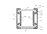
以下に、本発明を実施するための最良の形態について、添付図面を基に詳述する。図1は本発明の実施の形態である目隠しフェンスを概略的に示す図で、(a)は正面図、(b)は(a)のA−A線拡大断面図、図2は端部キャップを示す図で、(a)は正面図、(b)は底面図、(c)は側面図である。 The best mode for carrying out the present invention will be described below in detail with reference to the accompanying drawings. 1A and 1B are diagrams schematically showing a blindfold fence according to an embodiment of the present invention. FIG. 1A is a front view, FIG. 1B is an enlarged sectional view taken along line AA of FIG. (A) is a front view, (b) is a bottom view, and (c) is a side view.
図1において、1は目隠しフェンスであり、この目隠しフェンス1は、左右一対の支柱2と、これら支柱2間に左右方向に平行に配設された構造材である胴縁3と、これら胴縁3の正面にその長手方向に所定間隔で平行に配設された格子材4とから主に構成されている。上記支柱2は、例えば敷地や建物のベランダの手摺壁等に設置される。上記支柱2及び胴縁3は、例えばアルミ合金の押出形材からなっている。
In FIG. 1,
上記格子材4は、形材例えばアルミ合金の押出形材からなる一対の側枠5と、両側枠5間に介設される透明又は半透明な光透過材6と、両側枠5の端部に装着され上記光透過材6の端部を覆う端部キャップ7とを具備している。上記両側枠5は、左右対称形状をしている。側枠5は、左右の幅Dが10mm程度、前後の奥行きEが50mm程度とされている。側枠5の前部には一側面(内側面)に開口したスリット8が長手方向に連続して形成されることにより横断面略C字状とされた係合受部10が形成されていると共に、スリット8の近傍には端部キャップ7をネジ止めするネジ11を捩じ込むためのタッピングホール12が形成されている。また、側枠5の後部側は長手方向に連続した中空部13を有する構造(ホロー構造)とされている。側枠5には内部を前後に仕切る仕切壁14が形成され、この仕切壁14を挟んで前部側に係合受部10が形成され、後部側に中空部13が形成されている。また、上記仕切壁14の一部に上記タッピングホール12が形成されている。
The
一方、上記光透過材6は、板状のソリッド構造であり、その両側部には上記係合受部10にその長手方向からスライド可能に係合する係合部15が一体形成されている。図示例の場合、係合部15は側方に開口した断面略U字状に形成され、その一側には外向きのリブ16が長手方向に連続して形成されている。上記側枠5の係合受部10内には断面略U字状の係合部15の先端側両内側部に係合する一対のリブ17と、上記外向きのリブ16に係合する内向きのリブ18がそれぞれ長手方向に形成されている。
On the other hand, the
上記光透過材6は、合成樹脂形材からなっており、例えば水色等の着色が施されていることが好ましい。光透過材6は、透明であっても、半透明であっても良い。スリット8を内側に向けて配置した左右一対の側枠5の係合受部10に光透過材6の両係合部15を長手方向一端からスライド可能に係合させて両側枠5間に光透過材6を介設することにより、外面側に光透過材6を有する断面略U字状の格子材4が組立てられる。この組立状態において、光透過材6の外面は、側枠5の前端面よりも若干(2〜3mm程度)内側に後退した段落ち構造になっており、これにより光透過材6が傷つきにくい構造になっている。
The
上記端部キャップ7は、図2に示すように、上記格子材4の端面に当接されて該端面を覆うべく平面略U字状に形成された本体部20を有し、この本体部20には上記側枠5の中空部13に嵌合される嵌合部21と、上記光透過材6の端部の内外両面に沿ってそれぞれを覆うように立ち上がったカバー部22,23とが一体に形成されている。これらのカバー部22,23は、側枠5と光透過材6の熱膨張率の違いにより光透過材6の端部に発生する隙間を覆い隠すようになっている。上記本体部20にはこれをネジ止めすべく上記ネジ11を上記タッピングホール12に捩じ込むための孔部24が形成されている。上記タッピングホール12は、上記光透過材6の係合部15と接する部分が開口するように断面略C字状に形成されており、このタッピングホール12にネジ11が捩じ込まれると、光透過材6の係合部15にもネジ11が食い込まれ、これにより光透過材6の端部側と側枠5の端部側とが互いに結合され、熱膨張差により光透過材の端部が側枠5の端部よりも引っ込むのを抑制している。このように構成された格子材4は、図1(b)に示すように後端部が前記胴縁3に当接するように配置され、胴縁側から後端部にネジ25を捩じ込むことにより胴縁3に固定される。
As shown in FIG. 2, the
このように構成された目隠しフェンス1によれば、左右方向に平行に配設される胴縁(構造材)3と、該胴縁3の正面にその長手方向に所定間隔で平行に配設される格子材4とを備え、上記格子材4は、形材からなる一対の側枠5と、両側枠5間に介設される透明又は半透明な光透過材6と、両側枠5の端部に装着され上記光透過材6の端部を覆う端部キャップ7とを具備しているため、光透過率の向上が図れ、開放感のある明るい内観を実現できると共に外観の意匠性の向上が図れる。すなわち、上記格子材4の場合、各側枠の幅Dが10mm、光透過材6が装着される両側枠間の幅Fが30mmで格子材4全体の幅が50mmだとすると、該格子材4を50mm程度の隙間S(図1参照)が存するように100mmピッチで配設した場合、光透過率が80%になり、光透過率が50%の従来の目隠しフェンスに比して光透過率を60%向上させることができる。
According to the
また、上記格子材4の端部には端部キャップ7が取付けられ、この端部キャップ7には光透過材6の端部の内外面を覆うカバー部22,23を有しているため、光透過材6の端部の伸縮や切り口の粗さを覆い隠すことができ、意匠性の向上が図れる。上記格子材4にあっては、アルミと樹脂の複合構造のため、側枠5と光透過材6との間に暑さ寒さで伸び縮みの差が出易いが、タッピングホール12に捩じ込まれるネジ11で側枠5と光透過材6の二部材を結合し、端部キャップ7と側枠5と光透過材6の三部材を同時にネジ固定する構造であるため、側枠5と光透過材6の端部のずれを防止することができる。また、上記光透過材6においては、ソリッド形状であるため、切断時の切粉も簡単に除去することができる。
Further, an
図3〜図7は格子材の変形例を示す概略的断面図であり、図8〜図10は本発明の実施の形態ではない参考例を示す概略的断面図である。これらの図において、図1(b)と同一部分は同一参照符号を付して説明を省略する。図3の格子材4は、両側枠5の前後の奥行きを短くしたものである。図4の格子材4は、側枠5の前部側を中空部26を有するホロー構造として前方へ延出させ、格子材4を横断面H字状に形成したものである。この場合、光透過材6の係合部15にタッピングホール33が形成されており、側枠5にはタッピングホール33にネジ11が捩じ込まれる際に該ネジ11が食い込む突条部34が形成されている。図5の格子材4は、図4の格子材4の両側枠5の前後の奥行きを短くしたものである。
3 to 7 are Ri schematic sectional view showing a modification of the grating material, 8 to 10 Ru schematic sectional view showing a reference example not in the form of embodiment of the present invention. In these drawings, the same parts as those in FIG. The
図6の格子材4は、図4の格子材4の一方の側枠5の外側面27を断面円弧状に膨らませて形成したものである。図7の格子材4は、両側枠5の後部側にも係合受部10を形成して光透過材6を介設し、両側枠5と両光透過材6により囲まれた中空部28を有する横断面中空方形状に形成したものである。図8の格子材4は、図7の格子材4の前後の光透過材6同士を左右一対の連結板部30で連結して一体形成し、光透過材6を中空部31を有する一体構造にすると共に、光透過材6の係合部15の形状を簡素化したものである。図9の格子材4は、図8の格子材4における一体構造の光透過材6の中空部31をなくした構造としたものである。図10の格子材4は、左右の側枠5を前後に長い横断面長方形の中空構造とし、両側枠5の前端部間に板状の光透過材6を掛け渡した状態に取付け、該光透過材6の前面両側部に縦長の装飾材32を取付けたものである。
The
以上、本発明の実施の形態を図面により詳述してきたが、本発明は前記実施の形態に限定されるものではなく、本発明の要旨を逸脱しない範囲での種々の設計変更等が可能である。例えば、前記実施の形態の目隠しフェンスは、構造材を左右方向に平行に配設し、該構造材の正面にその長手方向に所定間隔で垂直の格子材を平行に配設して成るが、目隠しフェンスとしては、構造材を上下方向に平行に配設し、該構造材の正面にその長手方向に所定間隔で水平の格子材を平行に配設して成るものであってもよい。 Although the embodiments of the present invention have been described in detail with reference to the drawings, the present invention is not limited to the above-described embodiments, and various design changes and the like can be made without departing from the scope of the present invention. is there. For example, the blindfold fence of the above embodiment is configured by arranging the structural material in parallel in the left-right direction and arranging the lattice material perpendicular to the longitudinal direction at a predetermined interval in parallel on the front surface of the structural material. As the blindfold fence, a structural material may be arranged in parallel in the vertical direction, and a horizontal lattice material may be arranged in parallel at a predetermined interval in the longitudinal direction on the front surface of the structural material.
1 目隠しフェンス
3 胴縁(構造材)
4 格子材
5 側枠
6 光透過材
7 端部キャップ
4
Claims (3)
Priority Applications (1)
| Application Number | Priority Date | Filing Date | Title |
|---|---|---|---|
| JP2007066820A JP5108340B2 (en) | 2007-03-15 | 2007-03-15 | Blindfold fence |
Applications Claiming Priority (1)
| Application Number | Priority Date | Filing Date | Title |
|---|---|---|---|
| JP2007066820A JP5108340B2 (en) | 2007-03-15 | 2007-03-15 | Blindfold fence |
Publications (3)
| Publication Number | Publication Date |
|---|---|
| JP2008223414A JP2008223414A (en) | 2008-09-25 |
| JP2008223414A5 JP2008223414A5 (en) | 2010-02-18 |
| JP5108340B2 true JP5108340B2 (en) | 2012-12-26 |
Family
ID=39842340
Family Applications (1)
| Application Number | Title | Priority Date | Filing Date |
|---|---|---|---|
| JP2007066820A Active JP5108340B2 (en) | 2007-03-15 | 2007-03-15 | Blindfold fence |
Country Status (1)
| Country | Link |
|---|---|
| JP (1) | JP5108340B2 (en) |
Families Citing this family (3)
| Publication number | Priority date | Publication date | Assignee | Title |
|---|---|---|---|---|
| JP6675123B2 (en) * | 2016-02-17 | 2020-04-01 | 株式会社ニューメタル工業 | Combination of louver and connecting member, louver and connecting member |
| JP2021092026A (en) * | 2019-12-06 | 2021-06-17 | 株式会社ワークスタジオ | Partition fence |
| JP2021147941A (en) * | 2020-03-23 | 2021-09-27 | 株式会社Lixil | Door body |
Family Cites Families (1)
| Publication number | Priority date | Publication date | Assignee | Title |
|---|---|---|---|---|
| JP2004204499A (en) * | 2002-12-24 | 2004-07-22 | Matsushita Electric Works Ltd | Fence |
-
2007
- 2007-03-15 JP JP2007066820A patent/JP5108340B2/en active Active
Also Published As
| Publication number | Publication date |
|---|---|
| JP2008223414A (en) | 2008-09-25 |
Similar Documents
| Publication | Publication Date | Title |
|---|---|---|
| JP7467560B2 (en) | Fittings | |
| US4223499A (en) | Decorative stained glass insert unit for windows | |
| US3129793A (en) | Sunshade panel unit | |
| JP2008223414A (en) | Blindfold fence | |
| KR101091953B1 (en) | Curtain wall structure | |
| JP6259344B2 (en) | Composite fixture fixing members and composite fixtures | |
| KR101565961B1 (en) | Middle frame and and frame for windows and doors | |
| JP6100542B2 (en) | Guide rails for architectural shutters | |
| BE1016572A6 (en) | IMPROVED WINDOW OR DOOR PROFILE. | |
| JP7059142B2 (en) | Continuous windows | |
| KR100941985B1 (en) | A transparent soundproofed plate assembly | |
| JP6906394B2 (en) | Door and curtain wall unit | |
| JP6715115B2 (en) | Joinery frame and joinery | |
| JP6608755B2 (en) | Doors and joinery | |
| JP7184701B2 (en) | carport | |
| JP5673410B2 (en) | Lighting fixture | |
| JP2010084397A (en) | Fitting | |
| JP4907496B2 (en) | Curtain wall unit and curtain wall | |
| JP4708829B2 (en) | Soundproofing panels for buildings | |
| JP7441758B2 (en) | curtain wall unit | |
| JP5083827B2 (en) | Joinery | |
| JP7717378B2 (en) | Roof panels | |
| JP3924727B2 (en) | Face lattice | |
| JP5060238B2 (en) | Panel mounting structure | |
| AU2017100288A4 (en) | An external element for a building |
Legal Events
| Date | Code | Title | Description |
|---|---|---|---|
| A521 | Written amendment |
Free format text: JAPANESE INTERMEDIATE CODE: A523 Effective date: 20091225 Free format text: JAPANESE INTERMEDIATE CODE: A821 Effective date: 20091225 |
|
| A521 | Written amendment |
Free format text: JAPANESE INTERMEDIATE CODE: A821 Effective date: 20100115 |
|
| A621 | Written request for application examination |
Free format text: JAPANESE INTERMEDIATE CODE: A621 Effective date: 20100115 |
|
| A131 | Notification of reasons for refusal |
Free format text: JAPANESE INTERMEDIATE CODE: A131 Effective date: 20120417 |
|
| A521 | Written amendment |
Free format text: JAPANESE INTERMEDIATE CODE: A523 Effective date: 20120613 Free format text: JAPANESE INTERMEDIATE CODE: A821 Effective date: 20120613 |
|
| RD04 | Notification of resignation of power of attorney |
Free format text: JAPANESE INTERMEDIATE CODE: A7424 Effective date: 20120801 |
|
| TRDD | Decision of grant or rejection written | ||
| A01 | Written decision to grant a patent or to grant a registration (utility model) |
Free format text: JAPANESE INTERMEDIATE CODE: A01 Effective date: 20121002 |
|
| A01 | Written decision to grant a patent or to grant a registration (utility model) |
Free format text: JAPANESE INTERMEDIATE CODE: A01 |
|
| A61 | First payment of annual fees (during grant procedure) |
Free format text: JAPANESE INTERMEDIATE CODE: A61 Effective date: 20121005 |
|
| R150 | Certificate of patent or registration of utility model |
Free format text: JAPANESE INTERMEDIATE CODE: R150 Ref document number: 5108340 Country of ref document: JP Free format text: JAPANESE INTERMEDIATE CODE: R150 |
|
| FPAY | Renewal fee payment (event date is renewal date of database) |
Free format text: PAYMENT UNTIL: 20151012 Year of fee payment: 3 |
|
| S111 | Request for change of ownership or part of ownership |
Free format text: JAPANESE INTERMEDIATE CODE: R313111 |
|
| R350 | Written notification of registration of transfer |
Free format text: JAPANESE INTERMEDIATE CODE: R350 |