JP5103873B2 - Electrostatic ultrasonic transducer drive control method, electrostatic ultrasonic transducer, ultrasonic speaker using the same, audio signal reproduction method, superdirective acoustic system, and display device - Google Patents
Electrostatic ultrasonic transducer drive control method, electrostatic ultrasonic transducer, ultrasonic speaker using the same, audio signal reproduction method, superdirective acoustic system, and display device Download PDFInfo
- Publication number
- JP5103873B2 JP5103873B2 JP2006307860A JP2006307860A JP5103873B2 JP 5103873 B2 JP5103873 B2 JP 5103873B2 JP 2006307860 A JP2006307860 A JP 2006307860A JP 2006307860 A JP2006307860 A JP 2006307860A JP 5103873 B2 JP5103873 B2 JP 5103873B2
- Authority
- JP
- Japan
- Prior art keywords
- electrode
- wave
- hole
- ultrasonic
- signal
- Prior art date
- Legal status (The legal status is an assumption and is not a legal conclusion. Google has not performed a legal analysis and makes no representation as to the accuracy of the status listed.)
- Expired - Fee Related
Links
Images


Classifications
-
- H—ELECTRICITY
- H04—ELECTRIC COMMUNICATION TECHNIQUE
- H04R—LOUDSPEAKERS, MICROPHONES, GRAMOPHONE PICK-UPS OR LIKE ACOUSTIC ELECTROMECHANICAL TRANSDUCERS; DEAF-AID SETS; PUBLIC ADDRESS SYSTEMS
- H04R19/00—Electrostatic transducers
- H04R19/02—Loudspeakers
-
- B—PERFORMING OPERATIONS; TRANSPORTING
- B06—GENERATING OR TRANSMITTING MECHANICAL VIBRATIONS IN GENERAL
- B06B—METHODS OR APPARATUS FOR GENERATING OR TRANSMITTING MECHANICAL VIBRATIONS OF INFRASONIC, SONIC, OR ULTRASONIC FREQUENCY, e.g. FOR PERFORMING MECHANICAL WORK IN GENERAL
- B06B1/00—Methods or apparatus for generating mechanical vibrations of infrasonic, sonic, or ultrasonic frequency
- B06B1/02—Methods or apparatus for generating mechanical vibrations of infrasonic, sonic, or ultrasonic frequency making use of electrical energy
- B06B1/0292—Electrostatic transducers, e.g. electret-type
Description
本発明は、広周波数帯域に亘って一定の高音圧を発生する静電型超音波トランスデューサの駆動制御方法、静電型超音波トランスデューサ、これを用いた超音波スピーカ、音声信号再生方法、超指向性音響システム及び表示装置に関する。 The present invention relates to a drive control method for an electrostatic ultrasonic transducer that generates a constant high sound pressure over a wide frequency band, an electrostatic ultrasonic transducer, an ultrasonic speaker using the ultrasonic transducer, an audio signal reproduction method, and superdirectivity The present invention relates to a sex sound system and a display device.
従来の超音波トランスデューサは圧電セラミックを用いた共振型がほとんどである。
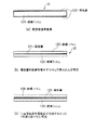
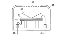
ここで、従来の超音波トランスデューサの構成を図15に示す。従来の超音波トランスデューサは、振動素子として圧電セラミックを用いた共振型がほとんどである。図15に示す超音波トランスデューサは、振動素子として圧電セラミックを用いて電気信号から超音波への変換と、超音波から電気信号への変換(超音波の送信と受信)の両方を行う。図15に示すバイモフル型の超音波トランスデューサは、2枚の圧電セラミック61および62と、コーン63と、ケース64と、リード65および66と、スクリーン67とから構成されている。
Most of conventional ultrasonic transducers are resonant types using piezoelectric ceramics.
Here, the configuration of a conventional ultrasonic transducer is shown in FIG. Most of conventional ultrasonic transducers are resonant types using piezoelectric ceramics as vibration elements. The ultrasonic transducer shown in FIG. 15 performs both conversion from an electric signal to ultrasonic waves and conversion from ultrasonic waves to electric signals (transmission and reception of ultrasonic waves) using a piezoelectric ceramic as a vibration element. The bimorphic ultrasonic transducer shown in FIG. 15 is composed of two
圧電セラミック61および62は、互いに貼り合わされていて、その貼り合わせ面と反対側の面にそれぞれリード65とリード66が接続されている。
共振型の超音波トランスデューサは、圧電セラミックの共振現象を利用しているので、超音波の送信および受信の特性がその共振周波数周辺の比較的狭い周波数帯域で良好となる。
The
Since the resonance type ultrasonic transducer uses the resonance phenomenon of the piezoelectric ceramic, the transmission and reception characteristics of the ultrasonic wave are good in a relatively narrow frequency band around the resonance frequency.
上述した図15に示す共振型の超音波トランスデューサと異なり、従来より静電方式の超音波トランスデューサは高周波数帯域にわたって高い音圧を発生可能な広帯域発振型超音波トランスデューサとして知られている。この静電型の超音波トランスデューサは、振動膜が固定電極側に引き付けられる方向のみ働くことからPull型と呼ばれている。
図16に広帯域発振型超音波トランスデューサ(Pull型)の具体的構成を示す。
Unlike the resonant ultrasonic transducer shown in FIG. 15 described above, an electrostatic ultrasonic transducer is conventionally known as a broadband oscillation ultrasonic transducer capable of generating a high sound pressure over a high frequency band. This electrostatic ultrasonic transducer is called a pull type because it works only in the direction in which the vibrating membrane is attracted to the fixed electrode side.
FIG. 16 shows a specific configuration of a broadband oscillation type ultrasonic transducer (Pull type).
図16に示す静電型の超音波トランスデューサは、振動体として3〜10μm程度の厚さのPET(ポリ・エチレン・テレフタレート樹脂)等の誘電体131(絶縁体)を用いている。誘電体131に対しては、アルミ等の金属箔として形成される上電極132がその上面部に蒸着等の処理によって一体形成されるとともに、真鍮で形成された下電極133が誘電体131の下面部に接触するように設けられている。この下電極133は、リード152が接続されるとともに、ベークライト等からなるベース板135に固定されている。
The electrostatic ultrasonic transducer shown in FIG. 16 uses a dielectric 131 (insulator) such as PET (polyethylene terephthalate resin) having a thickness of about 3 to 10 μm as a vibrating body. An
また、上電極132は、リード153が接続されており、このリード153は直流バイアス電源150に接続されている。この直流バイアス電源150により上電極132には50〜150V程度の上電極吸着用の直流バイアス電圧が常時、印加され上電極132が下電極133側に吸着されるようになっている。151は信号源である。
The
誘電体131および上電極132ならびにベース板135は、メタルリング136、137、および138、ならびにメッシュ139とともに、ケース130によってかしめられている。
下電極133の誘電体131側の面には不均一な形状を有する数十〜数百μm程度の微小な溝が複数形成されている。この微小な溝は、下電極133と誘電体131との間の空隙となるので、上電極132および下電極133間の静電容量の分布が微小に変化する。
The dielectric 131, the
On the surface of the
このランダムな微小な溝は、下電極133の表面を手作業でヤスリにより荒らすことで形成されている。静電方式の超音波トランスデューサでは、このようにして空隙の大きさや深さの異なる無数のコンデンサを形成することによって、図16に示す超音波トランスデューサの周波数特性が図17において曲線Q1に示すように広帯域となっている。
These random minute grooves are formed by manually roughing the surface of the
上記構成の超音波トランスデューサでは、上電極132に直流バイアス電圧が印加された状態で上電極12と下電極133との間に矩形波信号(50〜150Vp-p)が印加されるようになっている。因みに、図17に曲線Q2で示すように共振型の超音波トランスデューサの周波数特性は、中心周波数(圧電セラミックの共振周波数)が例えば、40kHzであり、最大音圧となる中心周波数に対して±5kHzの周波数において最大音圧に対して−30dBである。
これに対して、上記構成の広帯域発振型の超音波トランスデューサの周波数特性は、40kHzから100kHz付近まで平坦で、100kHzで最大音圧に比して±6dB程度である(特許文献1、2参照)。
On the other hand, the frequency characteristics of the broadband oscillation type ultrasonic transducer having the above configuration are flat from 40 kHz to near 100 kHz, and are about ± 6 dB compared to the maximum sound pressure at 100 kHz (see
上述したように、図15に示す共振型の超音波トランスデューサと違い、図16に示す静電方式の超音波トランスデューサは従来から広周波数帯に亘って比較的高い音圧を発生させることが可能な広帯域超音波トランスデューサ(Pull型)として知られている。
しかしながら、音圧の最大値は図13に示すように、共振型の超音波トランスデューサが130dB以上であるのに比べ、静電型の超音波トランスデューサでは120dB以下と音圧が低く、超音波スピーカとして利用するには若干音圧が不足していた。
As described above, unlike the resonant ultrasonic transducer shown in FIG. 15, the electrostatic ultrasonic transducer shown in FIG. 16 can generate a relatively high sound pressure over a wide frequency band. It is known as a broadband ultrasonic transducer (Pull type).
However, as shown in FIG. 13, the maximum value of the sound pressure is 120 dB or less for the electrostatic ultrasonic transducer as compared with 130 dB or more for the resonance type ultrasonic transducer. Sound pressure was slightly insufficient for use.
ここで、超音波スピーカについて説明しておく。キャリア波と呼ばれる超音波周波数帯域の信号にオーディオ信号(可聴周波数帯の信号)でAM変調をかけ、この変調信号で超音波トランスデューサを駆動することにより、超音波を信号源のオーディオ信号で変調した状態の音波が空中に放射され、空気の非線形性により、空中で元のオーディオ信号が自己再生される、というものである。 Here, the ultrasonic speaker will be described. By applying AM modulation to an ultrasonic frequency band signal called a carrier wave with an audio signal (audible frequency band signal) and driving the ultrasonic transducer with this modulation signal, the ultrasonic wave was modulated with the audio signal of the signal source. The sound wave of the state is radiated in the air, and the original audio signal is self-regenerated in the air due to the nonlinearity of air.
つまり、音波は空気を媒体として伝播する粗密波であるので、変調された超音波が伝播する過程で、空気の密な部分と疎な部分な顕著に表れ、密な部分は音速が速く、疎な部分は音速が遅くなるので変調波自身に歪が生じ、その結果キャリア波(超音波)と可聴波(元オーディオ信号)に波形分離され、我々人間は20kHz以下の可聴音(元オーディオ信号)のみを聴くことができるという原理であり、一般にはパラメトリックアレイ効果と呼ばれている。 In other words, since sound waves are coarse and dense waves that propagate using air as a medium, the dense and sparse parts of air appear prominently in the process of propagation of modulated ultrasonic waves. Since the speed of sound is slow in this part, the modulation wave itself is distorted. As a result, the waveform is separated into a carrier wave (ultrasonic wave) and an audible wave (original audio signal), and we humans audible sound below 20 kHz (original audio signal) This is the principle that only listening can be heard, and it is generally called the parametric array effect.
上記のパラメトリック効果が十分現れるためには120dB以上の超音波音圧が必要であるが、静電型の超音波トランスデューサではこの数値を達成することが難しく、もっぱらPZTなどのセラミック圧電素子やPVDFなどの高分子圧電素子が超音波発信体として用いられてきた。
しかし、圧電素子はその材質を問わず鋭い共振点を有しており、その共振周波数で駆動して超音波スピーカとして実用化しているため、高い音圧を確保出来る周波数領域が極めて狭い。すなわち狭帯域であるといえる。
In order for the above parametric effect to appear sufficiently, an ultrasonic sound pressure of 120 dB or more is required. However, it is difficult to achieve this value with an electrostatic ultrasonic transducer, and ceramic piezoelectric elements such as PZT, PVDF, etc. The polymer piezoelectric element has been used as an ultrasonic transmitter.
However, since the piezoelectric element has a sharp resonance point regardless of the material, and is practically used as an ultrasonic speaker by being driven at the resonance frequency, the frequency region where a high sound pressure can be secured is extremely narrow. That is, it can be said that it is a narrow band.
一般に、人間の最大可聴周波数帯域は20Hz〜20kHzと云われており約20kHzの帯域を持つ。すなわち超音波スピーカにおいては、超音波領域で20kHzの周波数帯域に亘って高い音圧を確保しないと、元のオーディオ信号を忠実に復調することは不可能となる。従来の圧電素子を用いた共振型の超音波スピーカでは到底この20kHzという広帯域を忠実に再生(復調)することは困難であることは容易に理解できるであろう。 Generally, the maximum human audible frequency band is said to be 20 Hz to 20 kHz, and has a band of about 20 kHz. That is, in an ultrasonic speaker, it is impossible to faithfully demodulate the original audio signal unless a high sound pressure is ensured over a frequency band of 20 kHz in the ultrasonic region. It can be easily understood that it is difficult to faithfully reproduce (demodulate) this 20 kHz wide band with a conventional resonance type ultrasonic speaker using a piezoelectric element.
実際、従来の共振型の超音波トランスデューサを用いた超音波スピーカでは、(1)帯域が狭く再生音質が悪い、(2)AM変調度をあまり大きくすると復調音が歪むため最大でも0.5程度までしか変調度を上げられない、(3)入力電圧を上げると(ボリュームを上げると)圧電素子の振動が不安定となり、音が割れる。さらに電圧を上げると圧電素子自身が破壊され易い、(4)アレイ化や大型化、小型化が困難であり、それが故にコストが高い、といった問題が有った。 In fact, in an ultrasonic speaker using a conventional resonance type ultrasonic transducer, (1) the reproduction frequency is narrow with a narrow band, and (2) the demodulated sound is distorted if the AM modulation degree is increased too much, so that the maximum is only about 0.5. The degree of modulation cannot be increased. (3) When the input voltage is increased (when the volume is increased), the vibration of the piezoelectric element becomes unstable and the sound is broken. When the voltage is further increased, the piezoelectric element itself is liable to be destroyed, and (4) it is difficult to make an array, enlargement, and miniaturization.
これに対し図16に示した静電型の超音波トランスデューサ(Pull型)を用いた超音波スピーカは、上記従来技術の抱える課題をほぼ解決できるが、帯域を広くカバーできる反面、復調音が十分な音量であるためには絶対的な音圧が不足しているという問題を抱えていた。
また、Pull型の超音波トランスデューサは、静電力は固定電極側へのみ引き付ける方向にしか働かず振動膜(図12における上電極132に相当する。)の振動の対称性が保たれないため、超音波スピーカに用いる場合、振動膜の振動が直接、可聴音を発生させるという問題が有った。
On the other hand, the ultrasonic speaker using the electrostatic ultrasonic transducer (Pull type) shown in FIG. 16 can substantially solve the above-mentioned problems of the conventional technology, but can cover a wide band, but has sufficient demodulated sound. However, there was a problem that the absolute sound pressure was insufficient for the sound volume to be high.
In the Pull type ultrasonic transducer, the electrostatic force works only in the direction of attracting only to the fixed electrode side, and the symmetry of vibration of the vibrating membrane (corresponding to the
これに対して、我々は、広周波数帯域にわたってパラメトリックアレイ効果を得るのに十分に高い音圧レベルの音響信号を発生することができる超音波トランスデューサを既に提案している。この超音波トランスデューサは、導電層を有する振動膜を対向する位置に貫通穴が形成された一対の固定電極により挟持し、振動膜に直流バイアス電圧が印加された状態で一対の固定電極に交流信号を印加するように構成したものである。 On the other hand, we have already proposed an ultrasonic transducer capable of generating an acoustic signal with a sound pressure level that is sufficiently high to obtain a parametric array effect over a wide frequency band. In this ultrasonic transducer, a vibrating membrane having a conductive layer is sandwiched between a pair of fixed electrodes with through holes formed at opposing positions, and an AC signal is applied to the pair of fixed electrodes in a state where a DC bias voltage is applied to the vibrating membrane. Is applied.
この超音波トランスデューサは、Push−Pull型の超音波トランスデューサと呼ばれており、一対の固定電極により挟持された振動膜が交流信号の極性に応じた方向において静電吸引力と静電斥力を同時が同方向にかつ同時に受けるために、振動膜の振動をパラメトリックアレイ効果を得るのに十分に大きくすることができるだけでなく、振動の対称性が確保されるため、従来のPull型超音波トランスデューサに比して高い音圧を広周波数帯域にわたって発生させることができる。 This ultrasonic transducer is called a Push-Pull type ultrasonic transducer, and the vibrating membrane sandwiched between a pair of fixed electrodes simultaneously applies electrostatic attraction and electrostatic repulsion in the direction corresponding to the polarity of the AC signal. Since the vibrations of the diaphragm are sufficiently large to obtain the parametric array effect, and the symmetry of the vibration is ensured, the conventional Pull type ultrasonic transducer has In comparison, a high sound pressure can be generated over a wide frequency band.
しかしながら、このPush−Pull型の超音波トランスデューサは、音が抜ける貫通穴が比較的小面積であるためこのままでは、十分な音圧を空中に発生させることは困難であるという問題がある。
したがって、このような構造を有するPush−Pull型の超音波トランスデューサにおいても十分な音圧を発生させるための技術が必要とされていた。
さらに、広帯域なレンジに亘って高い音圧を発生することができれば、超音波トランスデューサとして付加価値が増す。
However, this Push-Pull type ultrasonic transducer has a problem that it is difficult to generate a sufficient sound pressure in the air as it is because the through-hole through which sound passes is relatively small in area.
Therefore, a technique for generating sufficient sound pressure is required even in a Push-Pull type ultrasonic transducer having such a structure.
Further, if a high sound pressure can be generated over a wide range, the added value as an ultrasonic transducer increases.
本発明は、このような事情に鑑みてなされたものであり、同一の駆動条件でより強力な超音波を発生することができる、電気−音響エネルギーの変換効率の向上を図ったPush−Pull型の静電型超音波トランスデューサを提供することを目的とする。 The present invention has been made in view of such circumstances, and is a Push-Pull type capable of generating a stronger ultrasonic wave under the same driving conditions and improving the conversion efficiency of electro-acoustic energy. It is an object of the present invention to provide an electrostatic ultrasonic transducer.
上記目的を達成するために本発明の静電型超音波トランスデューサの駆動制御方法は、貫通穴を有する第1の電極と、貫通穴を有する第2の電極と、前記第1の電極の前記貫通穴と前記第2の電極の前記貫通穴とが対をなすように配置されかつ前記第1の電極と前記第2の電極とからなる一対の電極に挟まれるとともに導電層を有し、該導電層に直流バイアス電圧が印加される振動膜とを含み、前記一対の電極間には超音波周波数帯のキャリア波を可聴周波数帯の信号波で変調した変調波が印加され、前記貫通穴を共鳴管として作用させることを特徴とする。 In order to achieve the above object, a drive control method for an electrostatic ultrasonic transducer according to the present invention includes a first electrode having a through hole, a second electrode having a through hole, and the penetration of the first electrode. A hole and the through hole of the second electrode are arranged so as to make a pair, and sandwiched between a pair of electrodes composed of the first electrode and the second electrode, and having a conductive layer, A vibration film to which a DC bias voltage is applied to the layer, and a modulation wave obtained by modulating a carrier wave in an ultrasonic frequency band with a signal wave in an audible frequency band is applied between the pair of electrodes, and the through hole is resonated. It is characterized by acting as a tube.
上記構成からなる本発明の静電型超音波トランスデューサの駆動方法では、第1の電極と、第2の電極の対向する位置に複数の貫通穴を有し、振動膜の導電層に直流バイアス電圧が印加された状態で、第1、第2の電極からなる一対の電極に駆動信号である交流信号が印加されるために、一対の電極に挟まれた振動膜は、交流信号の極性に応じた方向において、静電吸引力と静電斥力とを同方向に同時に受けるために、振動膜の振動を、パラメトリック効果を得るのに十分大きくすることができるだけでなく、振動の対称性が確保されるため、高い音圧を広周波数帯域に亘って発生させることができる。 In the driving method of the electrostatic ultrasonic transducer according to the present invention having the above-described configuration, the first electrode and the second electrode have a plurality of through holes at opposing positions, and a DC bias voltage is applied to the conductive layer of the vibrating membrane. Since an alternating current signal, which is a drive signal, is applied to the pair of electrodes including the first and second electrodes in a state where is applied, the vibration film sandwiched between the pair of electrodes is in accordance with the polarity of the alternating current signal. In order to receive both electrostatic attractive force and electrostatic repulsive force in the same direction in the same direction, the vibration of the diaphragm can be made large enough to obtain the parametric effect, and the symmetry of vibration is ensured. Therefore, a high sound pressure can be generated over a wide frequency band.
さらに、前記一対の電極に設けられた貫通穴を共鳴管として作用させるように静電型超音波トランスデューサが駆動制御される。したがって、広周波数帯域に亘って強い超音波を発生させることができ、電気−音響エネルギー変換効率を向上させることが可能となる。 Furthermore, the electrostatic ultrasonic transducer is driven and controlled so that the through holes provided in the pair of electrodes act as a resonance tube. Therefore, strong ultrasonic waves can be generated over a wide frequency band, and the electro-acoustic energy conversion efficiency can be improved.
また、本発明の静電型超音波トランスデューサの駆動制御方法は、貫通穴を有する第1の電極と、貫通穴を有する第2の電極と、前記第1の電極の前記貫通穴と前記第2の電極の前記貫通穴とが対をなすように配置されかつ前記第1の電極と前記第2の電極とからなる一対の電極に挟まれるとともに導電層を有し、該導電層に直流バイアス電圧が印加される振動膜とを含み、前記一対の電極間には超音波周波数帯のキャリア波を可聴周波数帯の信号波で変調した変調波が印加され、前記振動膜の機械的振動共振周波数と前記貫通穴の音響共鳴周波数とを一致もしくはほぼ一致させることを特徴とする。 Also, the drive control method for an electrostatic ultrasonic transducer according to the present invention includes a first electrode having a through hole, a second electrode having a through hole, the through hole of the first electrode, and the second electrode. The through hole of the electrode of the first electrode is disposed so as to make a pair and is sandwiched between a pair of electrodes composed of the first electrode and the second electrode, and has a conductive layer, and a DC bias voltage is applied to the conductive layer. A modulation wave obtained by modulating a carrier wave in an ultrasonic frequency band with a signal wave in an audible frequency band is applied between the pair of electrodes, and a mechanical vibration resonance frequency of the vibration film The acoustic resonance frequency of the through hole is matched or substantially matched.
上記構成からなる本発明の静電型超音波トランスデューサの駆動方法では、第1の電極と、第2の電極の対向する位置に複数の貫通穴を有し、振動膜の導電層に直流バイアス電圧が印加された状態で、第1、第2の電極からなる一対の電極に駆動信号である交流信号が印加されるために、一対の電極に挟持された振動膜は、交流信号の極性に応じた方向において、静電吸引力と静電斥力とを同方向に同時に受けるために、振動膜の振動を、パラメトリック効果を得るのに十分大きくすることができるだけでなく、振動の対称性が確保されるため、高い音圧を広周波数帯域に亘って発生させることができる。 In the driving method of the electrostatic ultrasonic transducer according to the present invention having the above-described configuration, the first electrode and the second electrode have a plurality of through holes at opposing positions, and a DC bias voltage is applied to the conductive layer of the vibrating membrane. Since an alternating current signal, which is a drive signal, is applied to the pair of electrodes including the first and second electrodes in a state where is applied, the vibrating membrane sandwiched between the pair of electrodes depends on the polarity of the alternating current signal. In order to receive both electrostatic attractive force and electrostatic repulsive force in the same direction in the same direction, the vibration of the diaphragm can be made large enough to obtain the parametric effect, and the symmetry of vibration is ensured. Therefore, a high sound pressure can be generated over a wide frequency band.
さらに、前記一対の電極に設けられた貫通穴を共鳴管として作用させ、振動膜の機械的振動共振周波数と貫通穴の音響共鳴周波数とを一致させるように静電型超音波トランスデューサが駆動制御される。したがって、広周波数帯域に亘って強い超音波を発生させることができ、電気−音響エネルギー変換効率を向上させることが可能となる。 Further, the electrostatic ultrasonic transducer is driven and controlled so that the through holes provided in the pair of electrodes act as a resonance tube so that the mechanical vibration resonance frequency of the vibrating membrane and the acoustic resonance frequency of the through hole coincide with each other. The Therefore, strong ultrasonic waves can be generated over a wide frequency band, and the electro-acoustic energy conversion efficiency can be improved.
また、本発明の静電型超音波トランスデューサは、貫通穴を有する第1の電極と、貫通穴を有する第2の電極と、前記第1の電極の前記貫通穴と前記第2の電極の前記貫通穴とが対をなすように配置されかつ前記第1の電極と前記第2の電極とからなる一対の電極に挟まれるとともに導電層を有し、該導電層に直流バイアス電圧が印加される振動膜とを含み、前記振動膜の機械的振動共振点となる共振周波数から求まる波長をλとしたとき、前記一対の固定電極の各々の厚さtを(λ/4)・nもしくは略(λ/4)・n(但し、λは超音波の波長、nは正の奇数)とし、前記一対の電極間には超音波周波数帯のキャリア波を可聴周波数帯の信号波で変調した変調波が印加されることを特徴とする。 The electrostatic ultrasonic transducer according to the present invention includes a first electrode having a through hole, a second electrode having a through hole, the through hole of the first electrode, and the second electrode. The through hole is disposed in a pair and is sandwiched between a pair of electrodes composed of the first electrode and the second electrode, and has a conductive layer, and a DC bias voltage is applied to the conductive layer. The thickness t of each of the pair of fixed electrodes is (λ / 4) · n or approximately (wherein λ is a wavelength obtained from a resonance frequency that is a mechanical vibration resonance point of the vibration film. λ / 4) · n (where λ is the wavelength of the ultrasonic wave and n is a positive odd number), and a modulated wave obtained by modulating a carrier wave in the ultrasonic frequency band with a signal wave in the audible frequency band between the pair of electrodes. Is applied.
上記構成からなる本発明の静電型超音波トランスデューサでは、第1の電極と、第2の電極の対向する位置に複数の貫通穴を有し、振動膜の導電層に直流バイアス電圧が印加された状態で、第1、第2の電極からなる一対の電極に駆動信号である交流信号が印加されるために、一対の電極に挟まれた振動膜は、交流信号の極性に応じた方向において、静電吸引力と静電斥力とを同方向に同時に受けるために、振動膜の振動を、パラメトリック効果を得るのに十分大きくすることができるだけでなく、振動の対称性が確保されるため、高い音圧を広周波数帯域に亘って発生させることができる。 In the electrostatic ultrasonic transducer according to the present invention having the above-described configuration, the first electrode and the second electrode have a plurality of through holes at opposing positions, and a DC bias voltage is applied to the conductive layer of the vibrating membrane. In this state, an alternating current signal that is a drive signal is applied to the pair of electrodes including the first and second electrodes, so that the vibration film sandwiched between the pair of electrodes is in a direction corresponding to the polarity of the alternating current signal. In order to receive the electrostatic attractive force and the electrostatic repulsive force simultaneously in the same direction, not only can the vibration of the vibrating membrane be sufficiently large to obtain a parametric effect, but also the symmetry of the vibration is ensured. High sound pressure can be generated over a wide frequency band.
さらに、前記振動膜の機械的振動共振点となる共振周波数から求まる波長をλとしたとき、前記一対の固定電極の各々の厚さtを(λ/4)・nもしくは略、(λ/4)・n(但し、λは超音波の波長、nは正の奇数)とすることにより、振動膜の機械的振動共振周波数と貫通穴の音響的共鳴周波数とを一致させ、各電極の貫通穴部分における電極の厚み部分が共鳴管を構成し、電極出口付近で音圧を最大とすることができ、Push−Pull型の超音波トランスデューサにおいて、同一の駆動条件でより強力な超音波を発生することができる。すなわち、Push−Pull型の超音波トランスデューサにおいて電気−音響エネルギーの変換効率の向上が図れる。 Furthermore, when the wavelength obtained from the resonance frequency serving as the mechanical vibration resonance point of the vibrating membrane is λ, the thickness t of each of the pair of fixed electrodes is (λ / 4) · n or substantially (λ / 4). ) · N (where λ is the wavelength of the ultrasonic wave, and n is a positive odd number), the mechanical vibration resonance frequency of the vibrating membrane and the acoustic resonance frequency of the through hole are made to coincide with each other. The thickness portion of the electrode in the portion constitutes a resonance tube, and the sound pressure can be maximized in the vicinity of the electrode outlet, and a push-pull type ultrasonic transducer generates stronger ultrasonic waves under the same driving conditions. be able to. That is, the conversion efficiency of electro-acoustic energy can be improved in the push-pull type ultrasonic transducer.
また、本発明の静電型超音波トランスデューサは、貫通穴を有する第1の電極と、貫通穴を有する第2の電極と、前記第1の電極の前記貫通穴と前記第2の電極の前記貫通穴とが対をなすように配置されかつ前記第1の電極と前記第2の電極とからなる一対の電極に挟まれるとともに導電層を有し、該導電層に直流バイアス電圧が印加される振動膜とを含み、前記振動膜の機械的振動共振点となる共振周波数から求まる波長をλとしたとき、前記一対の固定電極の各々の厚さtを、(λ/4)・n−λ/8≦t≦(λ/4)・n+λ/8(但し、λは超音波の波長、nは正の奇数)とし、前記一対の電極間には超音波周波数帯のキャリア波を可聴周波数帯の信号波で変調した変調波が印加されることを特徴とする。 The electrostatic ultrasonic transducer according to the present invention includes a first electrode having a through hole, a second electrode having a through hole, the through hole of the first electrode, and the second electrode. The through hole is disposed in a pair and is sandwiched between a pair of electrodes composed of the first electrode and the second electrode, and has a conductive layer, and a DC bias voltage is applied to the conductive layer. The thickness t of each of the pair of fixed electrodes is (λ / 4) · n−λ, where λ is a wavelength obtained from a resonance frequency that is a mechanical vibration resonance point of the vibration film. / 8 ≦ t ≦ (λ / 4) · n + λ / 8 (where λ is the wavelength of the ultrasonic wave and n is a positive odd number), and a carrier wave in the ultrasonic frequency band is audible between the pair of electrodes. A modulated wave modulated by the signal wave is applied.
上記構成からなる本発明の静電型超音波トランスデューサでは、第1の電極と、第2の電極の対向する位置に複数の貫通穴を有し、振動膜の導電層に直流バイアス電圧が印加された状態で、第1、第2の電極からなる一対の電極に駆動信号である交流信号が印加されるために、一対の電極に挟持された振動膜は、交流信号の極性に応じた方向において、静電吸引力と静電斥力とを同方向に同時に受けるために、振動膜の振動を、パラメトリック効果を得るのに十分大きくすることができるだけでなく、振動の対称性が確保されるため、高い音圧を広周波数帯域に亘って発生させることができる。 In the electrostatic ultrasonic transducer according to the present invention having the above-described configuration, the first electrode and the second electrode have a plurality of through holes at opposing positions, and a DC bias voltage is applied to the conductive layer of the vibrating membrane. In this state, an alternating current signal as a drive signal is applied to the pair of electrodes composed of the first and second electrodes, so that the vibration film sandwiched between the pair of electrodes is in a direction according to the polarity of the alternating current signal. In order to receive the electrostatic attractive force and the electrostatic repulsive force simultaneously in the same direction, not only can the vibration of the vibrating membrane be sufficiently large to obtain a parametric effect, but also the symmetry of the vibration is ensured. High sound pressure can be generated over a wide frequency band.
さらに、前記振動膜の機械的振動共振点となる共振周波数から求まる波長をλとしたとき、前記一対の電極の各々の厚さtを一対の電極の各々の厚さtを、(λ/4)・n−λ/8≦t≦(λ/4)・n+λ/8(但し、λは超音波の波長、nは正の奇数)とすることにより、振動膜の機械的振動共振周波数と貫通穴の音響的共鳴周波数とを一致させ、各電極の貫通穴部分における電極の厚み部分が共鳴管を構成し、電極出口付近で音圧を略、最大値近傍の値に設定することができ、Push−Pull型の超音波トランスデューサにおいて、同一の駆動条件でより強力な超音波を発生することができる。すなわち、Push−Pull型の超音波トランスデューサにおいて電気−音響エネルギーの変換効率の向上が図れる。 Further, when the wavelength obtained from the resonance frequency that is the mechanical vibration resonance point of the vibrating membrane is λ, the thickness t of each of the pair of electrodes is set to the thickness t of each of the pair of electrodes (λ / 4). ) · N−λ / 8 ≦ t ≦ (λ / 4) · n + λ / 8 (where λ is the wavelength of the ultrasonic wave and n is a positive odd number), the mechanical vibration resonance frequency and penetration of the vibrating membrane Match the acoustic resonance frequency of the hole, the thickness part of the electrode in the through-hole part of each electrode constitutes a resonance tube, the sound pressure near the electrode outlet can be set to a value near the maximum value, In the push-pull type ultrasonic transducer, a stronger ultrasonic wave can be generated under the same driving conditions. That is, the conversion efficiency of electro-acoustic energy can be improved in the push-pull type ultrasonic transducer.
また、本発明の静電型超音波トランスデューサは、貫通穴を有する第1の電極と、貫通穴を有する第2の電極と、前記第1の電極の前記貫通穴と前記第2の電極の前記貫通穴とが対をなすように配置されかつ前記第1の電極と前記第2の電極とからなる一対の電極に挟まれるとともに導電層を有し、該導電層に直流バイアス電圧が印加される振動膜とを含み、前記振動膜の機械的振動共振点となる共振周波数から求まる波長をλとしたとき、前記一対の固定電極のうち一方の厚さt1を(λ/4)・nもしくは略(λ/4)・n(但し、λは超音波の波長、nは正の奇数)とし、他方の厚さt2を(λ/4)・mもしくは略(λ/4)・m(但し、λは超音波の波長、mは正の偶数)とし、前記一対の電極間には超音波周波数帯のキャリア波を可聴周波数帯の信号波で変調した変調波が印加されることを特徴とする。 The electrostatic ultrasonic transducer according to the present invention includes a first electrode having a through hole, a second electrode having a through hole, the through hole of the first electrode, and the second electrode. The through hole is disposed in a pair and is sandwiched between a pair of electrodes composed of the first electrode and the second electrode, and has a conductive layer, and a DC bias voltage is applied to the conductive layer. The thickness t1 of the pair of fixed electrodes is (λ / 4) · n or approximately when the wavelength obtained from the resonance frequency serving as the mechanical vibration resonance point of the vibration film is λ. (Λ / 4) · n (where λ is the wavelength of the ultrasonic wave and n is a positive odd number), and the other thickness t2 is (λ / 4) · m or substantially (λ / 4) · m (where λ is the wavelength of the ultrasonic wave, m is a positive even number), and a carrier wave in the ultrasonic frequency band is allowed between the pair of electrodes. Wherein the modulated wave modulated by the signal wave in the frequency band is applied.
上記構成からなる静電型超音波トランスデューサでは、第1の電極と、第2の電極の対向する位置に複数の貫通穴を有し、振動膜の導電層に直流バイアス電圧が印加された状態で、第1、第2の電極からなる一対の電極に駆動信号である交流信号が印加されるために、一対の電極に挟まれた振動膜は、交流信号の極性に応じた方向において、静電吸引力と静電斥力とを同方向に同時に受けるために、振動膜の振動を、パラメトリック効果を得るのに十分大きくすることができるだけでなく、振動の対称性が確保されるため、高い音圧を広周波数帯域に亘って発生させることができる。 In the electrostatic ultrasonic transducer having the above-described configuration, the first electrode and the second electrode have a plurality of through holes at opposing positions, and a DC bias voltage is applied to the conductive layer of the vibrating membrane. Since the alternating current signal, which is the drive signal, is applied to the pair of electrodes including the first and second electrodes, the vibration film sandwiched between the pair of electrodes is electrostatic in the direction corresponding to the polarity of the alternating current signal. Since the suction force and electrostatic repulsive force are simultaneously received in the same direction, the vibration of the diaphragm can be made large enough to obtain a parametric effect, and the symmetry of the vibration is ensured, so that a high sound pressure is obtained. Can be generated over a wide frequency band.
さらに、前記振動膜の機械的振動共振点となる共振周波数から求まる波長をλとしたとき、前記一対の固定電極のうち一方の厚さt1を(λ/4)・nもしくは略(λ/4)・n(但し、λは超音波の波長、nは正の奇数)とし、他方の厚さt2を(λ/4)・mもしくは略(λ/4)・m(但し、λは超音波の波長、mは正の偶数)とすることにより、高い音圧の音を放射したい一方(前面)の電極の貫通部分における厚み部分が共鳴管を構成すると共に、振動膜の機械的振動共振周波数と貫通穴の音響的共鳴周波数とを一致させ、電極の貫通穴出口付近で音圧を最大とし、かつ音の放射を必要としない他方(背面)の電極の貫通穴部分における厚み部分では貫通穴出口付近で音圧を最小とすることができる。 Furthermore, when the wavelength obtained from the resonance frequency that is the mechanical vibration resonance point of the vibrating membrane is λ, the thickness t1 of one of the pair of fixed electrodes is (λ / 4) · n or substantially (λ / 4). ) · N (where λ is the wavelength of the ultrasonic wave and n is a positive odd number), and the other thickness t2 is (λ / 4) · m or substantially (λ / 4) · m (where λ is the ultrasonic wave) (Where m is a positive even number), the thickness portion of the through-hole of the electrode on the one side (front surface) that composes the resonance tube and the mechanical vibration resonance frequency of the vibrating membrane And the acoustic resonance frequency of the through-hole, the sound pressure is maximized near the through-hole exit of the electrode, and the through-hole in the through-hole portion of the other (back) electrode does not require sound radiation. Sound pressure can be minimized near the exit.
したがって、Push‐Pull型の静電型超音波トランスデューサにおいて、同一の駆動条件でより強力な超音波を一方(前面側)の電極から広周波数帯域に亘って発生することができるだけでなく、他方(背面側)の電極からの音の放射を小さく抑制することができる。すなわち、Push−Pull型の超音波トランスデューサにおいて電気−音響エネルギーの変換効率の向上が図れる。 Therefore, in the push-pull type electrostatic ultrasonic transducer, not only can a stronger ultrasonic wave be generated from one (front side) electrode over a wide frequency band under the same driving condition, but the other ( Sound emission from the electrode on the back side can be reduced. That is, the conversion efficiency of electro-acoustic energy can be improved in the push-pull type ultrasonic transducer.
また、本発明の静電型超音波トランスデューサは、貫通穴を有する第1の電極と、貫通穴を有する第2の電極と、前記第1の電極の前記貫通穴と前記第2の電極の前記貫通穴とが対をなすように配置されかつ前記第1の電極と前記第2の電極とからなる一対の電極に挟まれるとともに導電層を有し、該導電層に直流バイアス電圧が印加される振動膜とを含み、前記振動膜の機械的振動共振点となる共振周波数から求まる波長をλとしたとき、前記一対の固定電極の各々の厚さt1,t2を、(λ/4)・n−λ/8≦t1≦(λ/4)・n+λ/8(但し、λは超音波の波長、nは正の奇数)(λ/4)・m−λ/8≦t2≦(λ/4)・m+λ/8(但し、λは超音波の波長、mは正の偶数であり、m=0のとき、t2は右辺の値のみとり得る。)とし、前記一対の電極間には超音波周波数帯のキャリア波を可聴周波数帯の信号波で変調した変調波が印加されることを特徴とする。 The electrostatic ultrasonic transducer according to the present invention includes a first electrode having a through hole, a second electrode having a through hole, the through hole of the first electrode, and the second electrode. The through hole is disposed in a pair and is sandwiched between a pair of electrodes composed of the first electrode and the second electrode, and has a conductive layer, and a DC bias voltage is applied to the conductive layer. The thickness t1, t2 of each of the pair of fixed electrodes is (λ / 4) · n, where λ is a wavelength obtained from a resonance frequency that is a mechanical vibration resonance point of the vibration film. −λ / 8 ≦ t1 ≦ (λ / 4) · n + λ / 8 (where λ is the wavelength of the ultrasonic wave and n is a positive odd number) (λ / 4) · m−λ / 8 ≦ t2 ≦ (λ / 4) ) · M + λ / 8 (where λ is the wavelength of the ultrasonic wave, m is a positive even number, and when m = 0, t2 can take only the value on the right side.) And, wherein the pair of electrodes, characterized in that the modulated wave obtained by modulating the carrier wave in the ultrasonic frequency band in the signal wave in the audio frequency band is applied.
上記構成からなる静電型超音波トランスデューサでは、第1の電極と、第2の電極の対向する位置に複数の貫通穴を有し、振動膜の導電層に直流バイアス電圧が印加された状態で、第1、第2の電極からなる一対の電極に駆動信号である交流信号が印加されるために、一対の電極に挟まれた振動膜は、交流信号の極性に応じた方向において、静電吸引力と静電斥力とを同方向に同時に受けるために、振動膜の振動を、パラメトリック効果を得るのに十分大きくすることができるだけでなく、振動の対称性が確保されるため、高い音圧を広周波数帯域に亘って発生させることができる。 In the electrostatic ultrasonic transducer having the above-described configuration, the first electrode and the second electrode have a plurality of through holes at opposing positions, and a DC bias voltage is applied to the conductive layer of the vibrating membrane. Since the alternating current signal, which is the drive signal, is applied to the pair of electrodes including the first and second electrodes, the vibration film sandwiched between the pair of electrodes is electrostatic in the direction corresponding to the polarity of the alternating current signal. Since the suction force and electrostatic repulsive force are simultaneously received in the same direction, the vibration of the diaphragm can be made large enough to obtain a parametric effect, and the symmetry of the vibration is ensured, so that a high sound pressure is obtained. Can be generated over a wide frequency band.
さらに、前記振動膜の機械的振動共振点となる共振周波数から求まる波長をλとしたとき、前記一対の固定電極の各々の厚さt1,t2を、(λ/4)・n−λ/8≦t1≦(λ/4)・n+λ/8(但し、λは超音波の波長、nは正の奇数)、(λ/4)・m−λ/8≦t2≦(λ/4)・m+λ/8(但し、λは超音波の波長、mは正の偶数であり、m=0のとき、t2は右辺の値のみとり得る。)とすることにより、高い音圧の音を放射したい一方(前面)の電極の貫通部分における厚み部分が共鳴管を構成すると共に、振動膜の機械的振動共振周波数と貫通穴の音響的共鳴周波数とを一致させ、電極の貫通穴出口付近で音圧を最大とし、かつ音の放射を必要としない他方(背面)の電極の貫通穴部分における厚み部分では貫通穴出口付近で音圧を最小とすることができる。 Furthermore, when the wavelength obtained from the resonance frequency serving as the mechanical vibration resonance point of the vibrating membrane is λ, the thicknesses t1 and t2 of the pair of fixed electrodes are respectively (λ / 4) · n−λ / 8. ≦ t1 ≦ (λ / 4) · n + λ / 8 (where λ is the wavelength of the ultrasonic wave and n is a positive odd number), (λ / 4) · m−λ / 8 ≦ t2 ≦ (λ / 4) · m + λ / 8 (where λ is the wavelength of the ultrasonic wave, m is a positive even number, and when m = 0, t2 can take only the value on the right side) The thickness part of the through-hole of the electrode on the (front surface) constitutes a resonance tube, and the mechanical vibration resonance frequency of the vibrating membrane and the acoustic resonance frequency of the through-hole are matched, so that the sound pressure is increased near the through-hole exit of the electrode. In the thickness part of the through-hole part of the other (back) electrode that is the maximum and does not require sound emission, the sound near the outlet of the through-hole It is possible to minimize.
したがって、Push‐Pull型の静電型超音波トランスデューサにおいて、同一の駆動条件でより強力な超音波を一方(前面側)の電極から広周波数帯域に亘って発生することができるだけでなく、他方(背面側)の電極からの音の放射を小さく抑制することができる。すなわち、Push−Pull型の超音波トランスデューサにおいて電気−音響エネルギーの変換効率の向上が図れる。 Therefore, in the push-pull type electrostatic ultrasonic transducer, not only can a stronger ultrasonic wave be generated from one (front side) electrode over a wide frequency band under the same driving condition, but the other ( Sound emission from the electrode on the back side can be reduced. That is, the conversion efficiency of electro-acoustic energy can be improved in the push-pull type ultrasonic transducer.
また、本発明の静電型超音波トランスデューサは、前記一対の電極に形成された穴は円柱状に形成された貫通穴であることを特徴とする。
このように構成した本発明の静電型超音波トランスデューサでは、振動膜の振動により発生する超音波が一対の電極が有する円柱状の貫通穴を介して放射される。この円柱状の貫通穴は、製造が最も簡単であるという長所を有する。
In the electrostatic ultrasonic transducer according to the present invention, the holes formed in the pair of electrodes are through holes formed in a columnar shape.
In the electrostatic ultrasonic transducer of the present invention configured as described above, ultrasonic waves generated by the vibration of the vibrating membrane are radiated through the cylindrical through holes of the pair of electrodes. This cylindrical through hole has the advantage that it is the easiest to manufacture.
また、本発明の静電型超音波トランスデューサは、前記一対の電極に形成された穴は、直径及び深さが各々異なる少なくとも二種類以上のサイズの同心円柱状の穴が連なって形成された貫通穴であることを特徴とする。 In the electrostatic ultrasonic transducer according to the present invention, the hole formed in the pair of electrodes is a through hole formed by connecting at least two types of concentric cylindrical holes having different diameters and depths. It is characterized by being.
このように構成した本発明の静電型超音波トランスデューサでは、一対の電極に直径および深さが各々異なる少なくとも二種類以上のサイズの同心円柱状の穴が連なった貫通穴が形成される。したがって、一対の電極に形成された上記二種類以上のサイズの同心円柱状の各穴の縁部分に並行する電極部分が振動膜の導電層と対向するように構成されるため、平行コンデンサが形成される。
したがって、振動膜の前記各穴の縁部分に対向する部分が、持ち上げられると同時に、引き下げられる力が働くため振動膜の振動を大きくすることができる。
In the electrostatic ultrasonic transducer of the present invention configured as described above, a through hole is formed in which a pair of electrodes are connected with concentric cylindrical holes of at least two different sizes and diameters. Therefore, the parallel capacitor is formed because the electrode portion parallel to the edge portion of each of the two or more types of concentric cylindrical holes formed on the pair of electrodes is opposed to the conductive layer of the vibrating membrane. The
Therefore, the vibration film can be vibrated greatly because the part of the vibration film facing the edge of each hole is lifted and the pulling force acts at the same time.
また、本発明の静電型超音波トランスデューサは、前記一対の電極に形成された穴は、断面がテーパー状に形成されていることを特徴とする。
このように構成した本発明の静電型超音波トランスデューサでは、一対の電極に断面がテーパー状の貫通穴が形成されているため、この電極のテーパ−部分が、振動膜の導電層と対向するように構成され、平行コンデンサが形成される。
したがって、前記電極のテーパ−部分に対向する振動膜の部分が、持ち上げられると同時に、引き下げられる力が働くため振動膜の振動を大きくすることができる。
The electrostatic ultrasonic transducer according to the present invention is characterized in that the holes formed in the pair of electrodes have a tapered cross section.
In the electrostatic ultrasonic transducer according to the present invention configured as described above, a through hole having a tapered cross section is formed in a pair of electrodes, and therefore the tapered portion of the electrode faces the conductive layer of the vibrating membrane. Thus, a parallel capacitor is formed.
Accordingly, the vibration film portion facing the taper portion of the electrode is lifted, and at the same time, the pulling force acts, so that the vibration of the vibration film can be increased.
また、本発明の静電型超音波トランスデューサは、前記一対の電極に形成された穴は、断面が矩形状の貫通穴であることを特徴とする。
このように構成した本発明の静電型超音波トランスデューサでは、振動膜の振動により発生する超音波が一対の電極に形成された断面が矩形状の貫通穴を介して放射される。この断面が矩形状に形成された貫通穴は、製造が最も簡単であるという長所を有する。
The electrostatic ultrasonic transducer according to the present invention is characterized in that the holes formed in the pair of electrodes are through holes having a rectangular cross section.
In the electrostatic ultrasonic transducer of the present invention configured as described above, the ultrasonic wave generated by the vibration of the vibrating membrane is radiated through the rectangular through hole formed in the cross section formed on the pair of electrodes. The through hole having a rectangular cross section has the advantage that it is the easiest to manufacture.
また、本発明の静電型超音波トランスデューサは、前記一対の電極に形成された穴は、同一中心線上に形成され長さが同一で幅および深さが各々異なる少なくとも二種類以上のサイズの矩形状穴が連なって形成された貫通穴であることを特徴とする。
このように構成した本発明の静電型超音波トランスデューサでは、一対の電極に同一中心線上に形成され長さが同一で幅および深さが各々異なる少なくとも二種類以上のサイズの矩形状の穴が連なった貫通穴が形成される。したがって、一対の電極に形成された上記二種類以上のサイズの矩形状の各穴の縁部分に並行する電極部分が振動膜の導電層と対向するように構成されるため、平行コンデンサが形成される。したがって、振動膜の前記各穴の縁部分に対向する部分が、持ち上げられると同時に、引き下げられる力が働くため振動膜の振動を大きくすることができる。
In the electrostatic ultrasonic transducer according to the present invention, the holes formed in the pair of electrodes are formed on the same center line, have the same length, and have at least two types of rectangular sizes having different widths and depths. It is a through-hole formed with a series of shape holes.
In the electrostatic ultrasonic transducer of the present invention configured as described above, at least two types of rectangular holes having the same length and different widths and depths are formed on the same center line in the pair of electrodes. A continuous through hole is formed. Accordingly, the parallel capacitor is formed because the electrode portion parallel to the edge portion of each of the two or more types of rectangular holes formed on the pair of electrodes is opposed to the conductive layer of the vibrating membrane. The Therefore, the vibration film can be vibrated greatly because the part of the vibration film facing the edge of each hole is lifted and the pulling force acts at the same time.
また、本発明の静電型超音波トランスデューサは、前記一対の電極に形成された穴は、前記一対の電極に形成された矩形状の貫通穴は平面が矩形状で、かつ断面がテーパー状に形成されていることを特徴とする。
このように構成した本発明の静電型超音波トランスデューサでは、一対の電極に平面が矩形状で、かつ断面がテーパー状の貫通穴が形成されているため、この電極のテーパ−部分が、振動膜の導電層と対向するように構成されるので、平行コンデンサが形成される。
したがって、前記電極のテーパ−部分に対向する振動膜の部分が、持ち上げられると同時に、引き下げられる力が働くため振動膜の振動を大きくすることができる。
Further, in the electrostatic ultrasonic transducer according to the present invention, the holes formed in the pair of electrodes have a rectangular through-hole formed in the pair of electrodes having a rectangular plane and a tapered section. It is formed.
In the electrostatic ultrasonic transducer according to the present invention configured as described above, since a through hole having a rectangular plane and a tapered cross section is formed in a pair of electrodes, the taper portion of the electrode vibrates. Since it is configured to face the conductive layer of the film, a parallel capacitor is formed.
Accordingly, the vibration film portion facing the taper portion of the electrode is lifted, and at the same time, the pulling force acts, so that the vibration of the vibration film can be increased.
また、本発明の静電型超音波トランスデューサは、前記一対の電極に形成された穴は、振動膜とは反対側に対して振動膜側の方が穴径が大きく、かつ深さが浅いことを特徴とする。
このように構成した本発明の静電型超音波トランスデューサでは、一対の電極に形成された穴は、振動膜とは反対側に対して振動膜側の方の穴径が大きく、且つ深さが浅いので、上記二種類以上のサイズの同心円柱状の各穴の縁部分に並行する固定電極部分が振動膜の導電層と対向するように構成されることにより平行コンデンサが形成されるので、振動膜の導電層に働く静電吸引力及び静電斥力を大きくすることができる。
In the electrostatic ultrasonic transducer according to the present invention, the hole formed in the pair of electrodes has a larger hole diameter and a shallower depth on the vibrating membrane side than on the opposite side of the vibrating membrane. It is characterized by.
In the electrostatic ultrasonic transducer of the present invention configured as described above, the hole formed in the pair of electrodes has a larger hole diameter on the vibration film side and a depth than the opposite side to the vibration film. Since it is shallow, a parallel capacitor is formed by configuring the fixed electrode portion parallel to the edge portion of each of the two or more types of concentric cylindrical holes facing the conductive layer of the vibration membrane. The electrostatic attractive force and electrostatic repulsive force acting on the conductive layer can be increased.
また、本発明の静電型超音波トランスデューサは、前記一対の電極に形成された矩形穴は、振動膜とは反対側に対して振動膜側の方が幅が大きく、かつ深さが浅いことを特徴とする。
このように構成した本発明の静電型超音波トランスデューサでは、一対の電極に形成された矩形穴は、振動膜とは反対側に対して振動膜側の方の幅が大きく、且つ深さが浅いので、上記二種類以上のサイズの矩形状の各穴の縁部分に並行する固定電極部分、または固定電極のテーパ−部分が振動膜の導電層と対向するように構成されることにより平行コンデンサが形成されるので、振動膜の導電層に働く静電吸引力及び静電斥力を大きくすることができる。
Further, in the electrostatic ultrasonic transducer according to the present invention, the rectangular hole formed in the pair of electrodes has a larger width and a shallower depth on the vibrating membrane side than on the opposite side of the vibrating membrane. It is characterized by.
In the electrostatic ultrasonic transducer of the present invention configured as described above, the rectangular hole formed in the pair of electrodes has a larger width and depth on the vibration film side than the vibration film on the opposite side. Since it is shallow, a parallel capacitor is formed by configuring the fixed electrode part parallel to the edge part of each of the two or more types of rectangular holes or the taper part of the fixed electrode to face the conductive layer of the vibrating membrane. Thus, the electrostatic attractive force and electrostatic repulsive force acting on the conductive layer of the vibrating membrane can be increased.
また、本発明の静電型超音波トランスデューサは、前記複数個の貫通穴は、各々同一サイズであることを特徴とする。
このように構成した本発明の静電型超音波トランスデューサでは、一対の電極に各々、同一サイズの貫通穴が形成される。したがって、穴加工が容易であり、製造コストの低減が図れる。
In the electrostatic ultrasonic transducer according to the present invention, the plurality of through holes may have the same size.
In the electrostatic ultrasonic transducer of the present invention configured as described above, through-holes of the same size are formed in each of the pair of electrodes. Therefore, drilling is easy and the manufacturing cost can be reduced.
また、本発明の静電型超音波トランスデューサは、前記複数個の貫通穴は、各々対向する位置では同一サイズであり、複数の穴サイズを有することを特徴とする。
このように構成した本発明の静電型超音波トランスデューサでは、一対の電極において各々対向する位置では同一サイズであり、複数の穴サイズの貫通穴が形成される。したがって、穴加工が容易であり、製造コストの低減が図れる。
The electrostatic ultrasonic transducer according to the present invention is characterized in that the plurality of through-holes have the same size at positions facing each other and have a plurality of hole sizes.
In the electrostatic ultrasonic transducer of the present invention configured as described above, a plurality of through-holes having the same size and a plurality of hole sizes are formed at positions facing each other in the pair of electrodes. Therefore, drilling is easy and the manufacturing cost can be reduced.
また、本発明の静電型超音波トランスデューサは、前記一対の電極は、単一の導電性部材からなることを特徴とする。
このように構成した本発明の静電型超音波トランスデューサでは、前記一対の電極は、単一の導電性部材、例えば、SUS、真鍮、鉄、ニッケル等の導電性材料で形成することができる。
The electrostatic ultrasonic transducer according to the present invention is characterized in that the pair of electrodes are made of a single conductive member.
In the electrostatic ultrasonic transducer of the present invention configured as described above, the pair of electrodes can be formed of a single conductive member, for example, a conductive material such as SUS, brass, iron, or nickel.
また、本発明の静電型超音波トランスデューサは、前記一対の電極は、複数の導電性部材からなることを特徴とする。
このように構成した本発明の静電型超音波トランスデューサでは、前記一対の電極は、複数の導電性部材で形成することができる。
The electrostatic ultrasonic transducer according to the present invention is characterized in that the pair of electrodes includes a plurality of conductive members.
In the electrostatic ultrasonic transducer of the present invention configured as described above, the pair of electrodes can be formed of a plurality of conductive members.
また、本発明の静電型超音波トランスデューサは、前記一対の電極は、導電性部材と絶縁部材とからなることを特徴とする。
このように構成した本発明の静電型超音波トランスデューサでは、前記一対の電極は、導電性部材と絶縁部材から構成される。例えば、ガラスエポキシ基板や紙フェノール基板等の絶縁部材に所望の穴加工をした後、ニッケルや金、銀、銅等でメッキ処理をすることにより、固定電極を導電性部材と絶縁部材で形成することができる。これにより、超音波トランスデューサの軽量化が図れる。
In the electrostatic ultrasonic transducer according to the present invention, the pair of electrodes includes a conductive member and an insulating member.
In the electrostatic ultrasonic transducer according to the present invention configured as described above, the pair of electrodes includes a conductive member and an insulating member. For example, after forming a desired hole in an insulating member such as a glass epoxy substrate or a paper phenol substrate, the fixed electrode is formed of a conductive member and an insulating member by plating with nickel, gold, silver, copper, or the like. be able to. Thereby, the weight of the ultrasonic transducer can be reduced.
また、本発明の静電型超音波トランスデューサは、前記振動膜は、絶縁性高分子フィルムの両面に電極層が形成された薄膜であることを特徴とする。
このように構成した本発明の超音波トランスデューサでは、振動膜は絶縁性高分子フィルムの両面に電極層が形成される。そしてこの場合に後述するように振動膜に対向する電極側には絶縁層が設けられる。したがって、振動膜の作製が容易になる。
In the electrostatic ultrasonic transducer according to the present invention, the vibration film is a thin film in which electrode layers are formed on both surfaces of an insulating polymer film.
In the ultrasonic transducer of the present invention configured as described above, the vibrating membrane has electrode layers formed on both surfaces of the insulating polymer film. In this case, as will be described later, an insulating layer is provided on the electrode side facing the vibration film. Therefore, the vibration film can be easily manufactured.
また、本発明の静電型超音波トランス絶縁性高分子フィルムの両面に電極層が形成された薄膜デューサは、前記振動膜は、電極層が2枚の絶縁性高分子フィルムで挟むように形成された薄膜であることを特徴とする。
このように構成した本発明の超音波トランスデューサでは、電極層を絶縁層(絶縁高分子フィルム)で挟むように振動膜が形成される。したがって、電極側の絶縁処理が不要になり、超音波トランスデューサの製造が容易になる。また、振動膜に対する電極の配置の対称性の確保が容易になる。
In addition, in the thin film transducer in which the electrode layers are formed on both surfaces of the electrostatic ultrasonic transformer insulating polymer film of the present invention, the vibration film is formed so that the electrode layer is sandwiched between two insulating polymer films. It is characterized by being a thin film.
In the ultrasonic transducer of the present invention configured as described above, the vibration film is formed so that the electrode layer is sandwiched between insulating layers (insulating polymer film). Therefore, the insulation treatment on the electrode side becomes unnecessary, and the manufacture of the ultrasonic transducer becomes easy. In addition, it becomes easy to ensure the symmetry of the arrangement of the electrodes with respect to the vibrating membrane.
また、本発明の静電型超音波トランスデューサは、前記振動膜は、絶縁性高分子フィルムの片面に電極層が形成された薄膜を2枚使用し、各々電極層同士を密着させて構成されていることを特徴とする。
このように構成した本発明の静電型超音波トランスデューサでは、絶縁性高分子フィルムの片面に電極層が形成された薄膜を2枚使用し、各々電極層同士を密着させることにより振動膜が形成される。したがって、振動膜の作製が容易となる。
Further, in the electrostatic ultrasonic transducer according to the present invention, the vibrating membrane is formed by using two thin films each having an electrode layer formed on one side of an insulating polymer film, and the electrode layers are in close contact with each other. It is characterized by being.
In the electrostatic ultrasonic transducer of the present invention configured as described above, a vibrating membrane is formed by using two thin films each having an electrode layer formed on one side of an insulating polymer film and bringing the electrode layers into close contact with each other. Is done. Therefore, the vibration film can be easily manufactured.
また、本発明の静電型超音波トランスデューサは、前記振動膜は、エレクトレットフィルムを用いていることを特徴とする。
このように構成した本発明の静電型超音波トランスデューサでは、前記振動膜は、エレクトレットフィルムが用いられる。この場合に電極側には絶縁層が形成される。したがって、振動膜の作製が容易となる。
The electrostatic ultrasonic transducer according to the present invention is characterized in that the vibrating membrane uses an electret film.
In the electrostatic ultrasonic transducer of the present invention configured as described above, an electret film is used as the vibration film. In this case, an insulating layer is formed on the electrode side. Therefore, the vibration film can be easily manufactured.
また、本発明の静電型超音波トランスデューサは、絶縁性高分子フィルムの両面に電極層が形成された薄膜である振動膜、またはエレクトレットフィルムを用いた振動膜を用いる場合は、前記一対の電極の各々振動膜側に電気的絶縁処理を施すことを特徴とする。
このように構成した本発明の静電型超音波トランスデューサでは、振動膜として絶縁層(絶縁フィルム)の両面に導電層(電極層)が形成された振動膜を使用する場合、あるいは振動膜としてエレクトレットフィルムを使用する場合には電極の振動膜側に電気的絶縁処理が施される。したがって、絶縁層(絶縁フィルム)の両面に導電層(電極層)が形成された両面電極蒸着膜や、エレクトレットフィルムを振動膜として使用することが可能となる。
In addition, the electrostatic ultrasonic transducer of the present invention uses the above-described pair of electrodes when using a vibration film that is a thin film in which electrode layers are formed on both surfaces of an insulating polymer film, or a vibration film that uses an electret film. An electrical insulation process is performed on each vibration film side.
In the electrostatic ultrasonic transducer according to the present invention configured as described above, when a vibration film having conductive layers (electrode layers) formed on both sides of an insulating layer (insulation film) is used as the vibration film, or an electret as the vibration film. When a film is used, an electrical insulation treatment is applied to the vibrating membrane side of the electrode. Therefore, it becomes possible to use a double-sided electrode vapor deposition film in which a conductive layer (electrode layer) is formed on both sides of an insulating layer (insulating film) or an electret film as a vibration film.
また、本発明の静電型超音波トランスデューサは、前記振動膜には、単一極性の直流バイアス電圧が印加されていることを特徴とする。
このように構成した本発明の静電型超音波トランスデューサでは、前記振動膜には、単一極性の直流バイアス電圧が印加される。したがって、振動膜の電極層には常に同極性の電荷が蓄積されるので、前記一対の電極に印加される交流信号により変化する電極の電圧の極性に応じて、振動膜が静電吸引力及び静電斥力を受け、振動する。
The electrostatic ultrasonic transducer according to the present invention is characterized in that a direct-current DC bias voltage is applied to the vibrating membrane.
In the electrostatic ultrasonic transducer of the present invention configured as described above, a DC bias voltage having a single polarity is applied to the vibrating membrane. Therefore, since electric charges having the same polarity are always accumulated in the electrode layer of the vibrating membrane, the vibrating membrane has an electrostatic attraction force and an electric potential according to the polarity of the voltage of the electrode that is changed by the AC signal applied to the pair of electrodes. Vibrates due to electrostatic repulsion.
また、本発明の静電型超音波トランスデューサは、前記電極と前記振動膜を保持する部材は絶縁材料で構成することを特徴とする。
このように構成した本発明の超音波トランスデューサでは、前記電極と振動膜を保持する部材は絶縁材料で構成される。したがって、電極と振動膜との間の電気的絶縁が保持される。
The electrostatic ultrasonic transducer according to the present invention is characterized in that the electrode and the member holding the vibration film are made of an insulating material.
In the ultrasonic transducer of the present invention configured as described above, the member that holds the electrode and the vibration film is made of an insulating material. Therefore, electrical insulation between the electrode and the vibrating membrane is maintained.
また、本発明の静電型超音波トランスデューサは、前記振動膜は膜表面上における直角四方向に張力をかけて固定されていることを特徴とする。
このように構成した本発明の超音波トランスデューサでは、前記振動膜は膜平面上における直角四方向に張力をかけて固定される。したがって、従来、振動膜を電極側に吸着させるために数百ボルトの直流バイアス電圧を振動膜に印加する必要があったが、振動膜の膜ユニット作製時に膜に張力をかけて固定することにより、従来、上記直流バイアス電圧が担っていた引張り張力と同様の作用をもたらすため、上記直流バイアス電圧を低減することができる。
In the electrostatic ultrasonic transducer according to the present invention, the vibrating membrane may be fixed by applying tension in four directions at right angles on the membrane surface.
In the ultrasonic transducer of the present invention configured as described above, the vibrating membrane is fixed by applying tension in four directions at right angles on the plane of the membrane. Therefore, conventionally, it has been necessary to apply a DC bias voltage of several hundred volts to the vibrating membrane in order to adsorb the vibrating membrane to the electrode side, but by applying tension to the membrane when fixing the membrane unit of the vibrating membrane, In addition, the DC bias voltage can be reduced because the same effect as the tensile tension that the DC bias voltage has conventionally performed is brought about.
また、本発明の静電型超音波トランスデューサは、貫通穴を有する第1の電極と、貫通穴を有する第2の電極と、前記第1の電極の前記貫通穴と前記第2の電極の前記貫通穴とが対をなすように配置されかつ前記第1の電極と前記第2の電極とからなる一対の電極に挟まれるとともに導電層を有し、該導電層に直流バイアス電圧が印加される振動膜とを含み、前記振動膜の機械的振動共振点となる共振周波数から求まる波長をλとしたとき、前記一対の固定電極の各々の厚さtを(λ/4)・nもしくは略(λ/4)・n(但し、λは超音波の波長、nは正の奇数)とし、前記一対の電極間には超音波周波数帯のキャリア波を可聴周波数帯の信号波で変調した変調波である交流信号が印加される静電型超音波トランスデューサの背面に、該背面の各開口部から放射された超音波を全て同じ長さの経路で前記静電型超音波トランスデューサの前面に放射する音響反射板を設置したことを特徴する。 The electrostatic ultrasonic transducer according to the present invention includes a first electrode having a through hole, a second electrode having a through hole, the through hole of the first electrode, and the second electrode. The through hole is disposed in a pair and is sandwiched between a pair of electrodes composed of the first electrode and the second electrode, and has a conductive layer, and a DC bias voltage is applied to the conductive layer. The thickness t of each of the pair of fixed electrodes is (λ / 4) · n or approximately (wherein λ is a wavelength obtained from a resonance frequency that is a mechanical vibration resonance point of the vibration film. λ / 4) · n (where λ is the wavelength of the ultrasonic wave and n is a positive odd number), and a modulated wave obtained by modulating a carrier wave in the ultrasonic frequency band with a signal wave in the audible frequency band between the pair of electrodes. The back surface of the electrostatic ultrasonic transducer to which an AC signal is applied is It features that it has established a sound reflecting plate for radiating the front surface of the electrostatic ultrasonic transducer of ultrasonic waves emitted by the path of all of the same length from each opening.
また、本発明の静電型超音波トランスデューサは、前記音響反射板は、超音波トランスデューサ背面の中心位置に一端が位置し、該中心位置を基準として超音波トランスデューサ背面の両側に対して45°の角度で配置され他端が超音波トランスデューサの端部と一致する長さの一対の第1の反射板と、一対の第1の反射板の前記端部と直角の角度をなして各々前記第1の反射板の外側方向に接続され前記第1の反射板長と同等の長さを有する一対の第2の反射板とを有していることを特徴とする In the electrostatic ultrasonic transducer according to the present invention, one end of the acoustic reflector is located at the center position on the back surface of the ultrasonic transducer, and the angle is 45 ° with respect to both sides of the back surface of the ultrasonic transducer with reference to the center position. A pair of first reflectors arranged at an angle and having the other end coincident with an end of the ultrasonic transducer, and an angle perpendicular to the ends of the pair of first reflectors, respectively. And a pair of second reflectors having a length equivalent to the length of the first reflector.
このように構成した本発明の超音波トランスデューサでは、第1の電極と、第2の電極の対向する位置に複数の貫通穴を有し、振動膜の導電層に直流バイアス電圧が印加された状態で、第1、第2の電極からなる一対の電極に駆動信号である交流信号が印加されるために、一対の電極に挟まれた振動膜は、交流信号の極性に応じた方向において、静電吸引力と静電斥力とを同方向に同時に受けるために、振動膜の振動を、パラメトリック効果を得るのに十分大きくすることができるだけでなく、振動の対称性が確保されるため、高い音圧を広周波数帯域に亘って発生させることができる。 In the ultrasonic transducer according to the present invention configured as described above, the first electrode and the second electrode have a plurality of through holes at opposing positions, and a DC bias voltage is applied to the conductive layer of the vibrating membrane. Therefore, since an alternating current signal as a drive signal is applied to the pair of electrodes including the first and second electrodes, the vibration film sandwiched between the pair of electrodes is static in the direction corresponding to the polarity of the alternating current signal. In order to receive both electrosuction force and electrostatic repulsive force in the same direction at the same time, the vibration of the diaphragm can be made large enough to obtain a parametric effect, and the symmetry of vibration is ensured, so that high sound The pressure can be generated over a wide frequency band.
また、前記振動膜の機械的振動共振点となる共振周波数から求まる波長をλとしたとき、前記一対の固定電極の各々の厚さtを(λ/4)・nもしくは略、(λ/4)・n(但し、λは超音波の波長、nは正の奇数)とすることにより、振動膜の機械的振動共振周波数と貫通穴の音響的共鳴周波数とを一致させ、各電極の貫通穴部分における電極の厚み部分が共鳴管を構成し、電極出口付近で音圧を最大とすることができ、Push−Pull型の超音波トランスデューサにおいて、同一の駆動条件で同一の駆動条件でより強力な超音波を発生することができる。すなわち、Push−Pull型の超音波トランスデューサにおいて電気−音響エネルギーの変換効率の向上が図れる。 In addition, when the wavelength obtained from the resonance frequency serving as the mechanical vibration resonance point of the vibrating membrane is λ, the thickness t of each of the pair of fixed electrodes is (λ / 4) · n or substantially (λ / 4). ) · N (where λ is the wavelength of the ultrasonic wave, and n is a positive odd number), the mechanical vibration resonance frequency of the vibrating membrane and the acoustic resonance frequency of the through hole are made to coincide with each other. The thickness part of the electrode in the part constitutes a resonance tube, and the sound pressure can be maximized in the vicinity of the electrode outlet. In the push-pull type ultrasonic transducer, the same driving condition and the same driving condition are more powerful. Ultrasound can be generated. That is, the conversion efficiency of electro-acoustic energy can be improved in the push-pull type ultrasonic transducer.
さらに、上記静電型超音波トランスデューサの背面に、該背面の各開口部から放射された超音波が全て同じ長さの経路で前記静電型超音波トランスデューサの前面に放射されるように音響反射板を設置することにより、すなわち、具体的には、超音波トランスデューサ背面の中心位置に一端が位置し、該中心位置を基準として超音波トランスデューサ背面の両側に対して45°の角度で配置され他端が超音波トランスデューサの端部と一致する長さの一対の第1の反射板と、一対の第1の反射板の前記端部と直角の角度をなして各々前記第1の反射板の外側方向に接続され前記第1の反射板長と同等の長さを有する一対の第2の反射板とで音響反射板を上記静電型超音波トランスデューサの背面に設置することにより、静電型超音波トランスデューサの背面から放出された超音波が音響反射板により前面に反射されるので、静電型超音波トランスデューサの前面及び背面から放出される超音波を有効活用することができる。 Further, acoustic reflection is performed on the back surface of the electrostatic ultrasonic transducer so that all the ultrasonic waves radiated from the openings on the back surface are radiated to the front surface of the electrostatic ultrasonic transducer through a path having the same length. By installing the plate, that is, specifically, one end is located at the center position of the back surface of the ultrasonic transducer, and the other end is disposed at an angle of 45 ° with respect to both sides of the back surface of the ultrasonic transducer with respect to the center position. A pair of first reflectors whose ends coincide with the ends of the ultrasonic transducers, and an outer side of each of the first reflectors at an angle perpendicular to the ends of the pair of first reflectors. An acoustic reflector is installed on the back surface of the electrostatic ultrasonic transducer by a pair of second reflectors connected in the direction and having a length equivalent to the length of the first reflector. Sonic transformer Since ultrasonic waves emitted from the rear of Yusa is reflected to the front by the sound reflecting plate, it is possible to effectively utilize ultrasonic waves emitted from the front and back of the electrostatic ultrasonic transducer.
また、本発明の超音波スピーカは、貫通穴を有する第1の電極と、貫通穴を有する第2の電極と、前記第1の電極の前記貫通穴と前記第2の電極の前記貫通穴とが対をなすように配置されかつ前記第1の電極と前記第2の電極とからなる一対の電極に挟まれるとともに導電層を有し、該導電層に直流バイアス電圧が印加される振動膜とを含み、前記振動膜の機械的振動共振点となる共振周波数から求まる波長をλとしたとき、前記一対の固定電極の各々の厚さtを(λ/4)・nもしくは略(λ/4)・n(但し、λは超音波の波長、nは正の奇数)とし、前記一対の電極間には超音波周波数帯のキャリア波を可聴周波数帯の信号波で変調した変調波が印加される静電型超音波トランスデューサと、可聴周波数帯の信号波を生成する信号源と、超音波周波数帯のキャリア波を生成し、出力するキャリア波供給手段と、前記キャリア波を前記信号源から出力される可聴周波数帯の信号波により変調する変調手段とを有し、前記静電型超音波トランスデューサは、前記一対の電極と前記振動膜の電極層との間に印加される前記変調手段から出力される変調信号により駆動されることを特徴とする。 The ultrasonic speaker according to the present invention includes a first electrode having a through hole, a second electrode having a through hole, the through hole of the first electrode, and the through hole of the second electrode. Are arranged so as to form a pair and are sandwiched between a pair of electrodes composed of the first electrode and the second electrode, and have a conductive layer, and a vibrating membrane to which a DC bias voltage is applied to the conductive layer, And the thickness t of each of the pair of fixed electrodes is (λ / 4) · n or substantially (λ / 4), where λ is a wavelength obtained from a resonance frequency that is a mechanical vibration resonance point of the vibration film ) · N (where λ is the wavelength of the ultrasonic wave and n is a positive odd number), and a modulated wave obtained by modulating a carrier wave in the ultrasonic frequency band with a signal wave in the audible frequency band is applied between the pair of electrodes. An electrostatic ultrasonic transducer, a signal source for generating a signal wave in an audible frequency band, A carrier wave supply means for generating and outputting a carrier wave in a sonic frequency band, and a modulation means for modulating the carrier wave with a signal wave in an audible frequency band outputted from the signal source, The acoustic wave transducer is driven by a modulation signal output from the modulation means applied between the pair of electrodes and the electrode layer of the vibrating membrane.
このように構成した本発明の超音波スピーカでは、信号源により可聴周波数帯の信号波が生成され、キャリア波供給手段により超音波周波数帯のキャリア波が生成され、出力される。さらに、変調手段によりキャリア波が前記信号源から出力される可聴周波数帯の信号波により変調され、この変調手段から出力される変調信号が前記固定電極と前記振動膜の電極層との間に印加され、駆動される。 In the ultrasonic speaker of the present invention configured as described above, an audible frequency band signal wave is generated by the signal source, and an ultrasonic frequency band carrier wave is generated and output by the carrier wave supply means. Further, the carrier wave is modulated by the audible frequency band signal wave output from the signal source by the modulation means, and the modulation signal output from the modulation means is applied between the fixed electrode and the electrode layer of the vibrating membrane. And driven.
本発明の超音波スピーカでは、上記構成の静電型超音波トランスデューサを用いて構成したので、広周波数帯域に亘ってパラメトリックアレイ効果を得るのに十分高い音圧レベルの音響信号を発生することができる超音波スピーカを実現できる。
また、本発明の超音波スピーカでは、振動膜の機械的振動共振周波数と貫通穴の音響的共鳴周波数とを一致させるように構成した静電型超音波トランスデューサを用いているので、広周波数帯域に亘って強力な超音波を発生でき、音質の向上が図れる。
Since the ultrasonic speaker according to the present invention is configured using the electrostatic ultrasonic transducer having the above-described configuration, it can generate an acoustic signal having a sound pressure level high enough to obtain a parametric array effect over a wide frequency band. Ultrasonic speaker that can be realized.
The ultrasonic speaker according to the present invention uses an electrostatic ultrasonic transducer configured to match the mechanical vibration resonance frequency of the vibrating membrane and the acoustic resonance frequency of the through hole. Powerful ultrasonic waves can be generated over the entire area, and sound quality can be improved.
また、本発明の静電型超音波トランスデューサによる音声信号再生方法は、貫通穴を有する第1の電極と、貫通穴を有する第2の電極と、前記第1の電極の前記貫通穴と前記第2の電極の前記貫通穴とが対をなすように配置されかつ前記第1の電極と前記第2の電極とからなる一対の電極に挟まれるとともに導電層を有し、該導電層に直流バイアス電圧が印加される振動膜とを含み、前記振動膜の機械的振動共振点となる共振周波数から求まる波長をλとしたとき、前記一対の固定電極の各々の厚さtを(λ/4)・nもしくは略(λ/4)・n(但し、λは超音波の波長、nは正の奇数)とし、前記一対の電極間には超音波周波数帯のキャリア波を可聴周波数帯の信号波で変調した変調波が印加される静電型超音波トランスデューサを使用すると共に、信号源により可聴周波数帯の信号波を生成する手順と、キャリア波供給手段により超音波周波数帯のキャリア波を生成し、出力する手順と、変調手段により前記キャリア波を前記可聴周波数帯の信号波により変調した変調信号を生成する手順と、前記電極と前記振動膜の電極層との間に前記変調信号を印加することにより前記静電型超音波トランスデューサを駆動する手順とを含むことを特徴とする。 Also, the audio signal reproduction method using the electrostatic ultrasonic transducer according to the present invention includes a first electrode having a through hole, a second electrode having a through hole, the through hole of the first electrode, and the first electrode. The through holes of the two electrodes are arranged to make a pair and are sandwiched between a pair of electrodes composed of the first electrode and the second electrode, and have a conductive layer, and a DC bias is applied to the conductive layer. The thickness t of each of the pair of fixed electrodes is (λ / 4), where λ is a wavelength obtained from a resonance frequency that is a mechanical vibration resonance point of the vibration membrane. · N or approximately (λ / 4) · n (where λ is the wavelength of the ultrasonic wave and n is a positive odd number), and a carrier wave in the ultrasonic frequency band is a signal wave in the audible frequency band between the pair of electrodes. Use an electrostatic ultrasonic transducer to which a modulated wave modulated by And a procedure for generating a signal wave in the audible frequency band by the signal source, a procedure for generating and outputting a carrier wave in the ultrasonic frequency band by the carrier wave supply means, and a carrier wave in the audible frequency band by the modulating means. A step of generating a modulation signal modulated by a signal wave, and a step of driving the electrostatic ultrasonic transducer by applying the modulation signal between the electrode and the electrode layer of the vibrating membrane. Features.
このような手順を含む本発明の静電型超音波トランスデューサの音声信号再生方法では、信号源により可聴周波数帯の信号波が生成され、またキャリア波供給源により超音波周波数帯のキャリア波が生成され、出力される。そして、変調手段によりキャリア波が前記可聴周波数帯の信号波により変調され、この変調信号が電極と振動膜の電極層との間に印加され、静電型超音波トランスデューサが駆動される。
これにより、上記構成の静電型超音波トランスデューサにより、電極間に印加する電圧が低電圧でかつ膜振動を増大でき、広周波数帯域にわたってパラメトリックアレイ効果を得るのに十分高い音圧レベルの音響信号を出力し、音声信号を再生することが可能になる。
また、本発明の静電型超音波トランスデューサの音声信号再生方法では、振動膜の機械的振動共振周波数と貫通穴の音響的共鳴周波数とを一致させるように構成した静電型超音波トランスデューサを用いているので、広周波数帯域に亘って強力な超音波を発生でき、再生音の音質の向上が図れる。
In the method of reproducing an audio signal of an electrostatic ultrasonic transducer according to the present invention including such a procedure, a signal wave in an audible frequency band is generated by a signal source, and a carrier wave in an ultrasonic frequency band is generated by a carrier wave supply source. And output. Then, the carrier wave is modulated by the signal wave in the audible frequency band by the modulating means, and this modulated signal is applied between the electrode and the electrode layer of the vibrating membrane, thereby driving the electrostatic ultrasonic transducer.
As a result, the electrostatic ultrasonic transducer having the above-described configuration can reduce the voltage applied between the electrodes and increase the membrane vibration, and an acoustic signal having a sufficiently high sound pressure level to obtain a parametric array effect over a wide frequency band. Can be output and an audio signal can be reproduced.
Further, in the audio signal reproducing method of the electrostatic ultrasonic transducer of the present invention, an electrostatic ultrasonic transducer configured to match the mechanical vibration resonance frequency of the vibrating membrane and the acoustic resonance frequency of the through hole is used. Therefore, strong ultrasonic waves can be generated over a wide frequency band, and the sound quality of the reproduced sound can be improved.
また、本発明の超指向性音響システムは、貫通穴を有する第1の電極と、貫通穴を有する第2の電極と、前記第1の電極の前記貫通穴と前記第2の電極の前記貫通穴とが対をなすように配置されかつ前記第1の電極と前記第2の電極とからなる一対の電極に挟まれるとともに導電層を有し、該導電層に直流バイアス電圧が印加される振動膜とを含み、前記振動膜の機械的振動共振点となる共振周波数から求まる波長をλとしたとき、前記一対の固定電極の各々の厚さtを(λ/4)・nもしくは略(λ/4)・n(但し、λは超音波の波長、nは正の奇数)とし、前記一対の電極間には超音波周波数帯のキャリア波を可聴周波数帯の信号波で変調した変調波が印加される静電型超音波トランスデューサを用いて構成され、音響ソースから供給される音声信号のうち中高音域の音声信号を再生する超音波スピーカと、前記音響ソースから供給される音声信号のうち低音域の音声信号を再生する低音再生用スピーカとを有し、前記超音波スピーカにより前記音響ソースから供給される音声信号を再生し、スクリーン等の音波反射面近傍に仮想音源を形成することを特徴とする。 Moreover, the super-directional acoustic system of the present invention includes a first electrode having a through hole, a second electrode having a through hole, the through hole of the first electrode, and the through of the second electrode. A vibration that is disposed so as to make a pair with a hole and is sandwiched between a pair of electrodes including the first electrode and the second electrode, and has a conductive layer, and a DC bias voltage is applied to the conductive layer. The thickness t of each of the pair of fixed electrodes is (λ / 4) · n or approximately (λ), where λ is a wavelength obtained from a resonance frequency that is a mechanical vibration resonance point of the vibration film. / 4) · n (where λ is the wavelength of the ultrasonic wave and n is a positive odd number), and a modulated wave obtained by modulating a carrier wave in the ultrasonic frequency band with a signal wave in the audible frequency band is between the pair of electrodes. Constructed using an applied electrostatic ultrasonic transducer and supplied from an acoustic source An ultrasonic speaker that reproduces an audio signal in the middle and high range among the audio signals to be reproduced, and a speaker for low tone reproduction that reproduces an audio signal in the low range from among the audio signals supplied from the acoustic source. A sound signal supplied from the acoustic source is reproduced by a speaker, and a virtual sound source is formed in the vicinity of a sound wave reflection surface such as a screen.
このように構成した本発明の超指向性音響システムでは、貫通穴を有する第1の電極と、該第1の電極の貫通穴と対をなす貫通穴を有する第2の電極と、前記第1と第2の電極からなる一対の電極に挟まれるとともに電極層を有し、該電極層に直流バイアス電圧が印加される振動膜とを有し、かつ前記一対の電極と前記振動膜とを保持し、前記一対の電極と前記振動膜の電極層との間に交流信号が印加される静電型超音波トランスデューサで構成される超音波スピーカを使用する。そして、この超音波スピーカにより、音響ソースから供給される音声信号のうち中高音域の音声信号を再生する。また、音響ソースから供給される音声信号のうち低音域の音声信号は低音再生用スピーカにより再生する。
したがって、中高音域の音響を、静電型超音波トランスデューサの電極間に印加される電圧が低電圧化され、かつ音圧特性が改善された状態で十分な音圧と広帯域特性を持って、スクリーン等の音波反射面近傍に形成される仮想音源から発せられるように再生できる。また、低音域の音響は、音響システムに備えられた低音再生用スピーカから直接出力されるので、低音域の補強ができ、より臨場感の高い音場環境を創生できる。
また、本発明の超指向性音響システムでは、振動膜の機械的振動共振周波数と貫通穴の音響的共鳴周波数とを一致させるように構成した静電型超音波トランスデューサを用いているので、広周波数帯域に亘って強力な超音波を発生でき、再生音の音質の向上が図れる。
In the superdirective acoustic system of the present invention configured as described above, the first electrode having a through hole, the second electrode having a through hole paired with the through hole of the first electrode, and the first electrode And a pair of electrodes composed of a second electrode and an electrode layer, and a vibration film to which a DC bias voltage is applied to the electrode layer, and holds the pair of electrodes and the vibration film In addition, an ultrasonic speaker constituted by an electrostatic ultrasonic transducer in which an AC signal is applied between the pair of electrodes and the electrode layer of the vibrating membrane is used. The ultrasonic speaker reproduces an audio signal in the middle / high range among the audio signals supplied from the acoustic source. Further, among the audio signals supplied from the acoustic source, the audio signal in the low frequency range is reproduced by a low tone reproduction speaker.
Therefore, it has sufficient sound pressure and wideband characteristics in the state that the voltage applied between the electrodes of the electrostatic ultrasonic transducer is lowered and the sound pressure characteristics are improved. It can be reproduced so as to be emitted from a virtual sound source formed in the vicinity of a sound wave reflecting surface such as a screen. Further, since the sound in the low frequency range is directly output from the low sound reproduction speaker provided in the sound system, the low frequency range can be reinforced and a more realistic sound field environment can be created.
Further, in the super directional acoustic system of the present invention, since the electrostatic ultrasonic transducer configured to match the mechanical vibration resonance frequency of the vibrating membrane and the acoustic resonance frequency of the through hole is used, Powerful ultrasonic waves can be generated over a band, and the sound quality of the reproduced sound can be improved.
また、本発明の表示装置は、貫通穴を有する第1の電極と、貫通穴を有する第2の電極と、前記第1の電極の前記貫通穴と前記第2の電極の前記貫通穴とが対をなすように配置されかつ前記第1の電極と前記第2の電極とからなる一対の電極に挟まれるとともに導電層を有し、該導電層に直流バイアス電圧が印加される振動膜とを含み、前記振動膜の機械的振動共振点となる共振周波数から求まる波長をλとしたとき、前記一対の固定電極の各々の厚さtを(λ/4)・nもしくは略(λ/4)・n(但し、λは超音波の波長、nは正の奇数)とし、前記一対の電極間には超音波周波数帯のキャリア波を可聴周波数帯の信号波で変調した変調波交流信号が印加される静電型超音波トランスデューサを含んで構成され、音響ソースから供給される音声信号から可聴周波数帯の信号音を再生する超音波スピーカと、映像を投影面に投影する投影光学系とを有することを特徴とする。 The display device of the present invention includes a first electrode having a through hole, a second electrode having a through hole, the through hole of the first electrode, and the through hole of the second electrode. A vibrating membrane disposed in a pair and sandwiched between a pair of electrodes composed of the first electrode and the second electrode and having a conductive layer, and a DC bias voltage is applied to the conductive layer. And the thickness t of each of the pair of fixed electrodes is (λ / 4) · n or substantially (λ / 4), where λ is a wavelength obtained from a resonance frequency serving as a mechanical vibration resonance point of the vibration film.・ N (where λ is the wavelength of the ultrasonic wave and n is a positive odd number), and a modulated wave AC signal obtained by modulating a carrier wave in the ultrasonic frequency band with a signal wave in the audible frequency band is applied between the pair of electrodes. And is supplied from an acoustic source And having an ultrasonic speaker for reproducing an acoustic signal in the audible frequency band from the voice signal, and a projection optical system for projecting an image onto a projection surface.
このように構成した本発明の表示装置では、貫通穴を有する第1の電極と、前記第1の電極の前記貫通穴と対をなす貫通穴を有する第2の電極と、前記第1と第2の電極からなる一対の電極に挟まれるとともに導電層を有し、該導電層に直流バイアス電圧が印加される振動膜とを有し、前記一対の電極と前記振動膜とを保持するとともに、前記振動膜の機械的振動共振点となる共振周波数から求まる波長をλとしたとき、前記一対の固定電極の各々の厚さtを(λ/4)・nもしくは略、(λ/4)・n(但し、λは超音波の波長、nは正の奇数)とし、前記一対の電極間には超音波周波数帯のキャリア波を可聴周波数帯の信号波で変調した変調波である交流信号が印加される静電型超音波トランスデューサを含んで構成される超音波スピーカを使用する。そして、この超音波スピーカにより、音響ソースから供給される音声信号を再生する。
これにより、音響信号を音圧特性が改善された状態で十分な音圧と広帯域特性を持って、スクリーン等の音波反射面近傍に形成される仮想音源から発せられるように再生できる。このため、音響信号の再生範囲の制御も容易に行えるようになる。また、超音波スピーカから放射される音の指向性制御を行うことが可能である。
また、本発明の超指向性音響システムでは、振動膜の機械的振動共振周波数と貫通穴の音響的共鳴周波数とを一致させるように構成した静電型超音波トランスデューサを用いているので、広周波数帯域に亘って強力な超音波を発生でき、再生音の音質の向上が図れる。
In the display device of the present invention configured as described above, the first electrode having a through hole, the second electrode having a through hole paired with the through hole of the first electrode, the first and first And having a conductive layer sandwiched between a pair of electrodes composed of two electrodes, and having a vibrating film to which a DC bias voltage is applied to the conductive layer, holding the pair of electrodes and the vibrating film, When the wavelength obtained from the resonance frequency serving as the mechanical vibration resonance point of the vibrating membrane is λ, the thickness t of each of the pair of fixed electrodes is (λ / 4) · n or substantially, (λ / 4) · n (where λ is the wavelength of the ultrasonic wave and n is a positive odd number), and an AC signal, which is a modulated wave obtained by modulating a carrier wave in the ultrasonic frequency band with a signal wave in the audible frequency band, is interposed between the pair of electrodes. Ultrasonic speaker comprising an applied electrostatic ultrasonic transducer To use. And the audio | voice signal supplied from an acoustic source is reproduced | regenerated by this ultrasonic speaker.
As a result, the sound signal can be reproduced so as to be emitted from a virtual sound source formed in the vicinity of a sound wave reflection surface such as a screen with sufficient sound pressure and wide band characteristics in a state where the sound pressure characteristics are improved. For this reason, it is possible to easily control the reproduction range of the acoustic signal. In addition, directivity control of sound radiated from the ultrasonic speaker can be performed.
Further, in the super directional acoustic system of the present invention, since the electrostatic ultrasonic transducer configured to match the mechanical vibration resonance frequency of the vibrating membrane and the acoustic resonance frequency of the through hole is used, Powerful ultrasonic waves can be generated over a band, and the sound quality of the reproduced sound can be improved.
以下、本発明の実施形態を、図面を参照して詳細に説明する。以下、本発明の実施形態を、図面を参照して詳細に説明する。本発明の実施形態に係る静電型超音波トランスデューサの構成を図1に示す。図1(A)は、静電型超音波トランスデューサの構成を示し、同図(B)は、静電型超音波トランスデューサの一部を破断した平面図を示している。
図1において、本発明の実施形態に係る静電型超音波トランスデューサ1は、電極として機能する導電性材料で形成された導電部材を含む一対の固定電極10A(第1の電極)、10B(第2の電極)と、一対の固定電極10A、10Bに挟さまれ、導電層121を有する振動膜12と、一対の固定電極10A、10Bと振動膜を保持する部材(図示せず)とを有している。
Hereinafter, embodiments of the present invention will be described in detail with reference to the drawings. Hereinafter, embodiments of the present invention will be described in detail with reference to the drawings. FIG. 1 shows the configuration of an electrostatic ultrasonic transducer according to an embodiment of the present invention. FIG. 1A shows a configuration of an electrostatic ultrasonic transducer, and FIG. 1B shows a plan view in which a part of the electrostatic ultrasonic transducer is broken.
In FIG. 1, an electrostatic
振動膜12は、絶縁体120で形成され、導電性材料で形成された電極層121を有しており、該電極層121には、直流バイアス電源16により単一極性(正極性でも負極性のいずれでもよい。)の直流バイアス電圧が印加されるようになっており、さらに、この直流バイアス電圧に重畳して固定電極10Aと固定電極10Bには、信号源18から出力される相互に位相反転した交流信号18A,18Bが電極層12との間に印加されるようになっている。
The vibrating
また、一対の固定電極10A、10Bは振動膜12を介して対向する位置に同数かつ複数の貫通穴14を有しており、一対の固定電極10A、10Bの導電部材間には信号源18により相互に位相反転した交流信号18A,18Bが印加されるようになっている。
固定電極10Aと電極層121、固定電極10Bと電極層121は、それぞれコンデンサが形成されている。
また、上記一対の固定電極10A、10Bの一方または双方における貫通穴は後述するように、共鳴管として作用するように固定電極の厚さtが設定されており、かつ静電型超音波トランスデューサ1は振動膜12の機械的振動共振周波数と貫通穴14の音響共振周波数とを一致させるよう駆動制御されるようになっている。
Further, the pair of fixed
The fixed
Further, as will be described later, the through hole in one or both of the pair of fixed
上記構成において、静電型超音波トランスデューサ1は、振動膜12の電極層に、直流バイアス電源16により単一極性の(本実施形態では正極性の)直流バイアス電圧に信号源18から出力される相互に位相反転した交流信号18A,18Bが重畳された状態で印加される。
一方、一対の固定電極10A、10Bには、信号源18より相互に位相反転した交流信号18A,18Bが印加される。
In the configuration described above, the electrostatic
On the other hand, AC signals 18A and 18B whose phases are inverted from each other are applied from the
この結果、信号源18から出力される交流信号18Aの正の半サイクルでは、固定電極10Aに正の電圧が印加されるために、振動膜12の固定電極で挟持されていない表面部分12Aには、静電反発力が作用し、表面部分12Aは、図1上、下方に引っ張られる。
また、このとき、交流信号18Bが負のサイクルとなり、対向する固定電極10Bには負の電圧が印加されるために、振動膜12の前記表面部分12Aの裏面側である裏面部分12Bには、静電吸引力が作用し、裏面部分12Bは、図1上、さらに下方に引っ張られる。
As a result, in the positive half cycle of the AC signal 18A output from the
At this time, since the AC signal 18B has a negative cycle and a negative voltage is applied to the opposed fixed
したがって、振動膜12の一対の固定電極10A、10Bにより挟まれていない膜部分は、同方向に静電反発力と静電斥力を受ける。これは、信号源18から出力される交流信号の負の半サイクルについても同様に、振動膜12の表面部分12Aには図1上、上方に静電吸引力が、また裏面部分12Bには、図1上、上方に静電反発力が作用し、振動膜12の一対の固定電極10A、10Bにより挟持されていない膜部分は、同方向に静電反発力と静電斥力を受ける。このとき、静電型超音波トランスデューサ1は振動膜12の機械的振動共振周波数と貫通穴14の音響共振周波数とを一致させるよう駆動制御される。具体的には、後述する。
Therefore, the membrane portion of the vibrating
このようにして、交流信号の極性の変化に応じて振動膜12が同方向に静電反発力と静電斥力を受けながら、交互に静電力が働く方向が変化するので、大きな膜振動、すなわち、パラメトリックアレイ効果を得るのに十分な音圧レベルの音響信号を発生することができるだけでなく、振動の対称性が確保されるため、高い音圧を広周波数帯域に亘って発生させることができる。
さらに、静電型超音波トランスデューサ1は、前記一対の固定電極に設けられた貫通穴14を共鳴管として作用させるように固定電極の厚さが設定され、振動膜12の機械的振動共振周波数と貫通穴14の音響共振周波数とを一致させるよう駆動制御される。
したがって、広周波数帯域に亘って強い超音波を発生させることができ、電気−音響エネルギー変換効率を向上させることが可能となる。
In this way, the direction in which the electrostatic force changes alternately while the vibrating
Furthermore, the electrostatic
Therefore, strong ultrasonic waves can be generated over a wide frequency band, and the electro-acoustic energy conversion efficiency can be improved.
このように本発明の実施形態に係る超音波トランスデューサ1は、振動膜12が一対の固定電極10A、10Bから力を受けて振動することからプッシュプル(Push―Pull)型と呼ばれている。
本発明の実施形態に係る超音波トランスデューサ1は、従来の、振動膜に静電吸引力のみしか作用しない静電型の超音波トランスデューサ(Pull型)に比して、広帯域性と高音圧を同時に満たす能力を持っている。
Thus, the
The
本発明の実施形態に係る超音波トランスデューサの周波数特性を図17に示す。同図において、曲線Q3が本実施形態に係る超音波トランスデューサの周波数特性である。同図から明らかなように、従来の広帯域型の静電型超音波トランスデューサの周波数特性に比して、より広い周波数帯にわたって、高い音圧レベルが得られることが分かる。具体的には、20kHz〜120kHzの周波数帯域においてパラメトリック効果が得られる120dB以上の音圧レベルが得られることが分かる。 FIG. 17 shows frequency characteristics of the ultrasonic transducer according to the embodiment of the present invention. In the figure, a curve Q3 is a frequency characteristic of the ultrasonic transducer according to the present embodiment. As can be seen from the figure, a higher sound pressure level can be obtained over a wider frequency band than the frequency characteristics of the conventional broadband electrostatic ultrasonic transducer. Specifically, it can be seen that a sound pressure level of 120 dB or more that can obtain a parametric effect in a frequency band of 20 kHz to 120 kHz can be obtained.
本発明の実施形態に係る超音波トランスデューサ1は一対の固定電極10A、10Bに挟持された薄膜の振動膜12が静電吸引力と静電斥力の両方を受けるため、大きな振動が発生するばかりでなく、振動の対称性が確保されるため、高い音圧を広帯域に亘って発生させることができるのである。
In the
次に、本実施形態に係る超音波トランスデューサの固定電極について説明する。図2は円柱状固定電極(一対の固定電極のうち片方の電極のみ)のいくつかの構成例(断面図)を示している。
図2(a)は貫通穴タイプであり、具体的には、一対の固定電極10A,10Bに形成された穴は、円柱状に形成された貫通穴である。この貫通穴が形成された固定電極は、製造は最も簡単であるが振動膜12と対向する電極に相当する部分がないため、静電力が弱いという欠点を有している。
Next, the fixed electrode of the ultrasonic transducer according to this embodiment will be described. FIG. 2 shows some configuration examples (cross-sectional views) of a cylindrical fixed electrode (only one of a pair of fixed electrodes).
FIG. 2A shows a through hole type. Specifically, the holes formed in the pair of fixed
図2(b)は2段貫通穴構造の固定電極の構造を示している。すなわち、一対の固定電極10A,10Bに形成された穴は、直径および深さが各々異なる少なくとも二種類以上(本実施形態では二種類)のサイズの同心円柱状の穴が連なって形成された貫通穴である。固定電極に形成された穴は、振動膜とは反対側に対して振動膜側の方の穴径が大きく、且つ深さが浅く形成されている。
この場合各穴の淵部分に並行する場所が振動膜12と対向しており、この部分が平行板コンデンサを構成している。
FIG. 2B shows the structure of a fixed electrode having a two-stage through-hole structure. That is, the holes formed in the pair of fixed
In this case, a place parallel to the flange portion of each hole is opposed to the
したがって振動膜12の淵部分が持ち上げられると同時に、引き下げられる力が働くため膜振動を大きくさせることができる。また図2(c)は断面がテーパー状の貫通穴を示している。この形状を固定電極として採用した場合の効果も図(b)における構成により得られる効果と同様である。
Therefore, at the same time that the heel portion of the vibrating
図3は溝形状の貫通穴を有する固定電極のいくつかの構成例(一対の固定電極のうち片方の電極のみ)を示している。図3(a)は貫通溝穴タイプで、一対の固定電極10A,10Bに形成された穴は、平面が矩形で、かつ断面が矩形状の貫通穴である。この貫通穴が形成された固定電極も製造は最も簡単であるが振動膜12と対向する電極に相当する部分がないため、静電力が弱いという欠点を有している。
FIG. 3 shows several configuration examples (only one of a pair of fixed electrodes) of the fixed electrode having a groove-shaped through hole. FIG. 3A shows a through-groove type, and the holes formed in the pair of fixed
図3(b)は2段貫通溝穴構造の固定電極の構成を示している。すなわち、一対の固定電極10A,10Bに形成された穴は、同一中心線上に形成され長さが同一で幅および深さが各々異なる少なくとも二種類以上(本実施形態では二種類)のサイズの平面が矩形状の穴が連なって形成された貫通穴である。
この場合、丸穴形状のときと同様に各溝穴の淵部分に並行する場所が振動膜12と対向しており、ここが平行板コンデンサを構成している。
したがって振動膜12の淵部分が持ち上げられると同時に、引き下げられる力が働くため振動膜12の膜振動を大きくさせることができる。
FIG. 3B shows a configuration of a fixed electrode having a two-stage through-slot structure. That is, the holes formed in the pair of fixed
In this case, as in the case of the round hole shape, the place parallel to the flange portion of each slot faces the vibrating
Accordingly, since the heel portion of the
また、図3(c)はテーパー状の貫通溝穴を示している。すなわち、一対の固定電極10A,10Bに形成された平面が矩形状の貫通穴は断面がテーパー状に形成されている。この形状を固定電極として採用した場合の効果も図3(b)における構成の固定電極と同様の効果が得られる。
なお、図3(b)、(c)の構成例において、固定電極に形成された矩形穴は、振動膜とは反対側に対して振動膜側の方の幅が大きく、且つ深さが浅くなるように形成されている。
FIG. 3C shows a tapered through-groove hole. In other words, the through hole having a rectangular plane formed in the pair of fixed
In the configuration examples of FIGS. 3B and 3C, the rectangular hole formed in the fixed electrode has a larger width and a smaller depth on the vibration film side than the opposite side to the vibration film. It is formed to become.
また、図2、図3に示した各構成例に示した、固定電極に形成された複数個の貫通穴は、各々同一サイズとしてもよい。
また、前記複数個の貫通穴は、各々対向する位置では同一サイズであり、複数の穴サイズを有するようにしてもよい。
The plurality of through holes formed in the fixed electrode shown in the respective configuration examples shown in FIGS. 2 and 3 may be the same size.
Further, the plurality of through holes may have the same size at positions facing each other, and may have a plurality of hole sizes.
本実施形態に係る超音波トランスデューサを構成する固定電極は、単一の導電性部材で構成してもよいし、複数の導電性部材で形成してもよい。
また、本実施形態に係る超音波トランスデューサを構成する固定電極は、導電性部材と絶縁部材から構成してもよい。
The fixed electrode constituting the ultrasonic transducer according to this embodiment may be constituted by a single conductive member or may be formed by a plurality of conductive members.
Further, the fixed electrode constituting the ultrasonic transducer according to the present embodiment may be composed of a conductive member and an insulating member.
具体的には、本実施形態に係る超音波トランスデューサの固定電極の材質は導電性であればよく例えばSUSや真鍮、鉄、ニッケルの単体構成も可能である。
また、軽量化を図る必要があるため、回路基板などで一般的に用いられるガラスエポシキ基板や紙フェノール基板に所望の穴加工を施した後、ニッケルや金、銀、銅などでメッキ処理をすることなども可能である。また、この場合成型後のソリを防止するために基板へのメッキ加工は両面に施すなどの工夫も有効である。
Specifically, the material of the fixed electrode of the ultrasonic transducer according to the present embodiment is only required to be conductive, and for example, a single structure of SUS, brass, iron, or nickel is possible.
In addition, since it is necessary to reduce the weight, a desired hole is drilled in a glass epoxy board or paper phenol board that is generally used for circuit boards, and then plated with nickel, gold, silver, copper, or the like. It is also possible. In this case, in order to prevent warping after molding, it is also effective to apply plating to the substrate on both sides.
ただし、振動膜12に、両面電極蒸着膜やエレクトレットフィルムを使う場合は、図1に示した超音波トランスデューサ1において、一対の固定電極10A,10Bの振動膜12側には何らかの絶縁処理が必要となる。例えば、アルミナ、珪素ポリマー系材料、アモルファス・カーボン膜、SiO2などで絶縁薄膜処理を施すなどの必要がある。
However, when a double-sided electrode vapor deposition film or an electret film is used for the
次に、振動膜12について説明する。振動膜12の機能は常に同極性の電荷を蓄積しておき(+の極性でも−の極性でもかまわない)、交流電圧で変化する固定電極10A,10B間で静電力により振動することである。本発明の実施形態に係る超音波トランスデューサにおける振動膜12の具体的構成例を、図4を参照して説明する。
Next, the
図4(a)は絶縁フィルム120の両面に電極蒸着処理を施し、電極層121を形成した振動膜12の断面構造を示している。中心の絶縁フィルム120は高分子材料、例えばポリ・エチレン・テレフタレート(PET)、ポリ・エステル、ポリ・エチレン・ナフタレート(PEN)、ポリ・フェニレン・サルファイド(PPS)などが伸縮性、電気耐圧的に好ましい。
FIG. 4A shows a cross-sectional structure of the vibrating
電極層121を形成する電極蒸着材料はAlが最も一般的で、その他、Ni、Cu、SUS、Tiなどが上記高分子材料との相性、コストなどの面から望ましい。振動膜12を形成する絶縁フィルム120としての絶縁性高分子フィルムの厚みは駆動周波数や固定電極に設けた穴サイズなどにより最適値が異なるため一意には決めかねるが、一般には1μm以上100μm以下の範囲でおおよそ十分であると思われる。
The electrode deposition material for forming the
電極層121としての電極蒸着層の厚みも40nm〜200nmの範囲が望ましい。電極厚みは薄すぎると電荷がほとんど蓄積できず、また厚すぎると膜が硬くなって振幅が小さくなるという問題につながってしまう。また、電極材料としては透明導電膜ITO/In,Sn,Zn酸化物などでも良い。
The thickness of the electrode deposition layer as the
図4(b)は電極層121を絶縁フィルム120としての絶縁性高分子フィルムで挟み込んだ構造を示している。このときの電極層121の厚みも図4(a)の場合と同様に40nm〜200nmの範囲が望ましい。また、電極層121それを挟む絶縁フィルム120の材質、厚さも図4(a)の両面電極蒸着膜と同様にポリ・エチレン・テレフタレート(PET)、ポリ・エステル、ポリ・エチレン・ナフタレート(PEN)、ポリ・フェニレン・サルファイド(PPS)、1μm以上100μm以下が望ましい。
FIG. 4B shows a structure in which the
図4(c)は片面電極蒸着膜を電極面が接触するように2枚張り合わせたものである。このときの絶縁膜および電極部の条件は上述した他の振動膜と同様の条件が望ましい。
また、振動膜12には数百ボルトの直流バイアス電圧が必要となるが、膜ユニット作製時に振動膜12の膜表面上における直角四方向に張力をかけて固定することにより、前記バイアス電圧は低減できる。
FIG. 4 (c) shows a case where two single-sided electrode deposition films are bonded together so that the electrode surfaces are in contact with each other. The conditions for the insulating film and the electrode part at this time are preferably the same as those for the other vibration films described above.
Further, the vibrating
これはあらかじめ膜に張力をかけておくことで、従来バイアス電圧が担っていた引っ張り張力と同様の作用をもたらすためであり、低電圧化のためには非常に有効な手段である。
この場合も膜電極材料としては、Alが最も一般的で、その他、Ni、Cu、SUS、Tiなどが上記高分子材料との相性、コストなどの面から望ましい。さらに透明導電膜ITO/In,Sn,Zn酸化物などでも良い。
This is because a tension is applied to the film in advance to bring about the same effect as the tensile tension that the bias voltage has conventionally been responsible for, which is a very effective means for lowering the voltage.
Also in this case, Al is the most common film electrode material, and Ni, Cu, SUS, Ti, etc. are desirable from the standpoint of compatibility with the polymer material and cost. Further, a transparent conductive film ITO / In, Sn, Zn oxide or the like may be used.
次に、上記固定電極あるいは振動膜の固定材料であるが、アクリル、ベークライト、ポリアセタール(ポリオキシメチレン)樹脂(POM)などのプラスチック系材料が、軽量、非導電性という観点から好ましい。 Next, as the fixing material for the fixed electrode or the diaphragm, plastic materials such as acrylic, bakelite, and polyacetal (polyoxymethylene) resin (POM) are preferable from the viewpoint of light weight and non-conductivity.
次に、本発明の実施形態に係る静電型超音波トランスデューサの要部の構成について説明する。図2及び図3を参照して既に固定電極の構造について説明したが、本発明の実施形態に係る一対の固定電極10A,10Bのいずれか一方または双方の固定電極の厚み部分が共鳴現象を生じる音響管である共鳴管を構成するようにその長さtが設定されている(図2参照)。
図5は、貫通穴(共鳴管)14が設けられた固定電極(共鳴管ユニット)10A(10B)の平面図であり、固定電極10A(10B)に設けられた貫通穴の配置の一例を示している。貫通穴の配置は図5に示したように規則的に配列されるとは限らない。
Next, the configuration of the main part of the electrostatic ultrasonic transducer according to the embodiment of the present invention will be described. Although the structure of the fixed electrode has already been described with reference to FIG. 2 and FIG. 3, the thickness of one or both of the pair of fixed
FIG. 5 is a plan view of the fixed electrode (resonance tube unit) 10A (10B) provided with the through hole (resonance tube) 14, and shows an example of the arrangement of the through holes provided in the fixed
また、貫通穴の長さは、構造上、固定電極の厚み部分の長さtが支配的であり、したがって、固定電極の貫通穴部分を共鳴管として使用するためには固定電極の厚み部分の長さtが共鳴管を構成するように決定される必要がある。
図6は、共鳴管の集合体である共鳴管ユニットとしての固定電極における音の共鳴状態を示した正面断面図である。図中tは共鳴管の長さを示しており、本例では1/2波長の音波が伝播する様子を示している。
In addition, the length of the through hole is dominated by the length t of the thickness portion of the fixed electrode because of the structure. Therefore, in order to use the through hole portion of the fixed electrode as a resonance tube, the thickness portion of the fixed electrode The length t needs to be determined so as to constitute a resonance tube.
FIG. 6 is a front cross-sectional view showing a state of sound resonance in a fixed electrode as a resonance tube unit that is an assembly of resonance tubes. In the figure, t indicates the length of the resonance tube, and in this example, a state in which a 1/2 wavelength sound wave propagates is illustrated.
共鳴現象を起こす最小の波長単位は1/2波長であり、両端開口端の共鳴現象の理論式は以下のようである。すなわち、fを超音波周波数、cを音速(約340m/s)、λを波長とすると、
λ=mc/f (1)
の関係がある(ただし、mは整数)。
ここで、最適音響管長をλopt,nを奇数の自然数とすると、
λopt=nc/4f (2)
で表せる。
The minimum wavelength unit that causes the resonance phenomenon is ½ wavelength, and the theoretical formula of the resonance phenomenon at both ends of the opening is as follows. That is, if f is the ultrasonic frequency, c is the speed of sound (about 340 m / s), and λ is the wavelength,
λ = mc / f (1)
(Where m is an integer).
Here, if the optimal acoustic tube length is λopt and n is an odd natural number,
λopt = nc / 4f (2)
It can be expressed as
音波の波長λが式(2)を満たすとき、音圧は音響管出口で最大となり、これが求める音響管(共鳴管)長、すなわち固定電極の厚み部分の長さtである。したがって、図6(b)が共鳴管ユニット、すなわち固定電極を最もコンパクトにする形態であるが、図中tは1/4波長の正の自然数倍であればいかなる値をとっても良い。
本発明の一実施例(第1実施例)では、例えば、図1に示した静電型超音波トランスデューサ1における振動膜12の機械的振動共振点となる共振周波数から求まる波長をλとしたとき、一対の固定電極10A,10Bの各々の厚さtを(λ/4)・nもしくは略、(λ/4)・n(但し、λは超音波の波長、nは正の奇数)とするように構成される。
When the wavelength λ of the sound wave satisfies the equation (2), the sound pressure becomes maximum at the acoustic tube outlet, and this is the desired acoustic tube (resonance tube) length, that is, the length t of the thickness portion of the fixed electrode. Therefore, FIG. 6B shows a configuration in which the resonance tube unit, that is, the fixed electrode is made most compact, but t may take any value as long as t is a positive natural number multiple of ¼ wavelength.
In one embodiment (first embodiment) of the present invention, for example, when the wavelength obtained from the resonance frequency that is the mechanical vibration resonance point of the
上記構成からなる本発明の静電型超音波トランスデューサでは、第1の固定電極10Aと、第2の固定電極10Bの対向する位置に複数の貫通穴14を有し、振動膜12の導電層121に直流バイアス電圧が印加された状態で、第1、第2の固定電極10A,10Bからなる一対の固定電極に駆動信号である交流信号が印加されるために、一対の固定電極10A,10Bに挟まれた振動膜12は、交流信号の極性に応じた方向において、静電吸引力と静電斥力とを同方向に同時に受けるために、振動膜12の振動をパラメトリック効果を得るのに十分大きくすることができるだけでなく、振動の対称性が確保されるため、高い音圧を広周波数帯域に亘って発生させることができる。
In the electrostatic ultrasonic transducer according to the present invention having the above-described configuration, the first
さらに、振動膜12の機械的振動共振点となる共振周波数から求まる波長をλとしたとき、前記一対の固定電極の各々の厚さtを(λ/4)・nもしくは略、(λ/4)・n(但し、λは超音波の波長、nは正の奇数)とすることにより、振動膜12の機械的振動共振周波数と音響的共鳴周波数とを一致させ、各固定電極の貫通穴部分における固定電極の厚み部分が共鳴管を構成し、固定電極出口付近で音圧を最大とすることができ、Push−Pull型の超音波トランスデューサにおいて、同一の駆動条件で同一の駆動条件でより強力な超音波を発生することができる。すなわち、Push−Pull型の超音波トランスデューサにおいて電気−音響エネルギーの変換効率の向上が図れる。
Furthermore, when the wavelength obtained from the resonance frequency serving as the mechanical vibration resonance point of the
共鳴管として機能させるための固定電極の厚さの一例を示せば、超音波の周波数が40kHzの場合、波長は8.5mmあるので、その1/4の2.125mmの共鳴管長(固定電極厚)tがあればよい。発生させるのが超音波であるので、20kHzを基準に取れば、波長は17mmである。したがって、その1/4の4.25mmの共鳴管長(固定電極厚)tがあればよい。
また、100kHzを基準に取れば、波長は3.4mmである。したがって、その1/4の0.85mmの共鳴管長(固定電極厚)tがあればよい。
If an example of the thickness of the fixed electrode for functioning as a resonance tube is shown, when the frequency of the ultrasonic wave is 40 kHz, the wavelength is 8.5 mm. ) T is sufficient. Since ultrasonic waves are generated, the wavelength is 17 mm when 20 kHz is taken as a reference. Therefore, the resonance tube length (fixed electrode thickness) t of 1/4 of 4.25 mm is sufficient.
Moreover, if 100 kHz is taken as a reference, the wavelength is 3.4 mm. Therefore, a resonance tube length (fixed electrode thickness) t of 1/4 of 0.85 mm is sufficient.
次に、図7に振動膜の機械的振動共振による音圧、音響共鳴による音圧、およびそれらの合成音圧(最終的な出力音圧)と周波数との関係を示す。図7(A)は、振動膜の機械的振動の一次共振周波数に貫通穴の音響共鳴周波数を一致させた場合であり、図7(B)は、
例えば振動膜の直径1500μm、厚さ12μm、音響管直径750μm、長さ1.1μmの場合、振動膜の機械的振動共振周波数(一次共振周波数)f1は30kHz付近となる。図7(A)は、振動膜の機械的振動の一次共振周波数f1と貫通穴の音響共鳴周波数が一致するように設計した例であるが、振動膜の一次共振周波数f1と一致するように貫通穴の音響共鳴周波数がくるように設計する以外にも、図7(B)に示すように振動膜の機械的振動の1二次共振周波数f2と一致するように貫通穴の音響共鳴周波数がくるように設計しても高音圧化が可能である。
Next, FIG. 7 shows the relationship between the sound pressure due to mechanical vibration resonance of the vibrating membrane, the sound pressure due to acoustic resonance, and their combined sound pressure (final output sound pressure) and frequency. FIG. 7A shows a case where the acoustic resonance frequency of the through hole is matched with the primary resonance frequency of the mechanical vibration of the vibrating membrane, and FIG.
For example, when the diaphragm has a diameter of 1500 μm, a thickness of 12 μm, an acoustic tube diameter of 750 μm, and a length of 1.1 μm, the mechanical vibration resonance frequency (primary resonance frequency) f1 of the diaphragm is approximately 30 kHz. FIG. 7A shows an example in which the primary resonance frequency f1 of the mechanical vibration of the vibrating membrane is designed to match the acoustic resonance frequency of the through hole. In addition to designing so that the acoustic resonance frequency of the hole comes, the acoustic resonance frequency of the through hole comes to coincide with the first secondary resonance frequency f2 of the mechanical vibration of the vibrating membrane as shown in FIG. 7B. Even if designed in this way, high sound pressure can be achieved.
また、固定電極の貫通穴を共鳴管として機能させるには、現実的には、次式(3)に示すように、固定電極の厚み部分の長さtの選択値にある程度の幅を持たせることがよい。
(λ/4)・n−λ/8≦t≦(λ/4)・n+λ/8 (3)
ただし、λは、超音波の波長(Hz)、nは正の奇数である。
また、
λ=c/f (4)
ただし、cは音速であり、c=331.3+0.6T(m/s)(ただし、Tは空気温度(℃))、fは超音波の周波数(Hz)である。
In order to make the through hole of the fixed electrode function as a resonance tube, in reality, as shown in the following equation (3), the selected value of the length t of the thickness portion of the fixed electrode is given a certain width. It is good.
(Λ / 4) · n−λ / 8 ≦ t ≦ (λ / 4) · n + λ / 8 (3)
Here, λ is the wavelength (Hz) of the ultrasonic wave, and n is a positive odd number.
Also,
λ = c / f (4)
Here, c is the speed of sound, c = 331.3 + 0.6 T (m / s) (where T is the air temperature (° C.)), and f is the ultrasonic frequency (Hz).
式(3)の意味するところは、共鳴管長の最適値の前後(±)1/8波長の範囲で共鳴管長(固定電極厚)を選択する、ということである。1/8波長というのは、最適値の約70%に相当し、それ以上ならその値を選択しても効率的には大きな損失は無いと推測される限界値である。 The meaning of equation (3) is that the resonance tube length (fixed electrode thickness) is selected in the range of (±) 1/8 wavelength before and after the optimum value of the resonance tube length. The 1/8 wavelength corresponds to about 70% of the optimum value, and if it is more than that, it is a limit value that is estimated to have no significant loss even if that value is selected.
図8に振動膜の機械的振動の1次共振周波数、キャリア波(超音波周波数帯)の波長λ、音響管長との関係の具体例を示す。同図における振動膜の機械的振動の1次共振周波数は、振動膜を規定するパラメータ(例えば、膜径、膜材料、膜厚等)を決定し振動膜の機械的振動の共振点、すなわち共振周波数(この例では、1次共振周波数)を決定する。次いで、この共振周波数にから求まる波長をλとすると、キャリア波(超音波)周波数fをλ=c/f(cは音速)(式(4))から決定する。
さらに、音響管長(固定電極の厚さ)を式(3)から決定する。このようにして求めた数値例が図8の内容である。
なお、本実施形態では、図1において、固定電極(共鳴管ユニット)10Aの底部と振動膜との間には実際には若干の隙間が設けられている(図面では隙間がなく、密着した状態になっているが)。この隙間は、開口端補正であり、一般には共鳴管半径の0.6〜0.85倍程度必要である。
FIG. 8 shows a specific example of the relationship between the primary resonance frequency of the mechanical vibration of the vibrating membrane, the wavelength λ of the carrier wave (ultrasonic frequency band), and the acoustic tube length. The primary resonance frequency of the mechanical vibration of the vibrating membrane in the figure determines the parameters (for example, the membrane diameter, membrane material, film thickness, etc.) that define the vibrating membrane, and the resonance point of mechanical oscillation of the vibrating membrane, that is, the resonance The frequency (in this example, the primary resonance frequency) is determined. Next, assuming that the wavelength obtained from this resonance frequency is λ, the carrier wave (ultrasound) frequency f is determined from λ = c / f (c is the speed of sound) (formula (4)).
Further, the acoustic tube length (thickness of the fixed electrode) is determined from the equation (3). A numerical example obtained in this way is the contents of FIG.
In this embodiment, in FIG. 1, a slight gap is actually provided between the bottom of the fixed electrode (resonance tube unit) 10A and the vibrating membrane (there is no gap in the drawing, and a close contact state). ) This gap is an opening end correction and generally needs to be about 0.6 to 0.85 times the radius of the resonance tube.
また、本原理を利用する場合には、共鳴管内径は音波長より十分小さく、管内では平面波が発生することが前提とされている。本発明の実施形態に係る静電型超音波トランスデューサの場合、発生する超音波は平面波であり、また管内径は大きくても2.1mm程度であるのでキャリア波として発振する超音波の周波数が20kHzの時の波長17mmに対して十分に小さい値であるので、全く問題ないと考えられる。 When this principle is used, it is assumed that the inner diameter of the resonance tube is sufficiently smaller than the sound wave length and that a plane wave is generated in the tube. In the case of the electrostatic ultrasonic transducer according to the embodiment of the present invention, the generated ultrasonic wave is a plane wave and the inner diameter of the tube is about 2.1 mm at most, so the frequency of the ultrasonic wave oscillated as a carrier wave is 20 kHz. Since the value is sufficiently small for the wavelength of 17 mm at this time, it is considered that there is no problem at all.
次に、本発明の実施形態に係る静電型超音波トランスデューサの第2実施例について説明する。この実施例では、前記振動膜の機械的振動共振点となる共振周波数から求まる波長をλとしたとき、図1に示した静電型超音波トランスデューサ1における一対の固定電極10A,10Bのうち一方の厚さt1をλ/4)・nもしくは略、(λ/4)・n(但し、λは超音波の波長、nは正の奇数)とし、他方の厚さt2を(λ/4)・mもしくは略、(λ/4)・m(但し、λは超音波の波長、mは正の偶数)とするように構成される。
Next, a second example of the electrostatic ultrasonic transducer according to the embodiment of the present invention will be described. In this embodiment, when the wavelength obtained from the resonance frequency serving as the mechanical vibration resonance point of the vibrating membrane is λ, one of the pair of fixed
上記構成からなる静電型超音波トランスデューサでは、第1の固定電極10Aと、第2の固定電極10Bの対向する位置に複数の穴14が形成され、振動膜14の導電層121に直流バイアス電圧が印加された状態で、第1、第2の固定電極10A.10Bからなる一対の固定電極10A.10Bに駆動信号である交流信号が印加されるために、一対の固定電極10A.10Bに挟持された振動膜14は、交流信号の極性に応じた方向において、静電吸引力と静電斥力とを同方向に同時に受けるために、振動膜14の振動をパラメトリック効果を得るのに十分大きくすることができるだけでなく、振動の対称性が確保されるため、高い音圧を広周波数帯域に亘って発生させることができる。
In the electrostatic ultrasonic transducer having the above-described configuration, a plurality of
さらに、振動膜14の機械的振動共振点となる共振周波数から求まる波長をλとしたとき、前記一対の固定電極のうち一方の厚さt1をλ/4)・nもしくは略、(λ/4)・n(但し、λは超音波の波長、nは正の奇数)とし、他方の厚さt2を(λ/4)・mもしくは略、(λ/4)・m(但し、λは超音波の波長、mは正の偶数)とすることにより、高い音圧の音を放射したい一方(前面)の固定電極の貫通部分における厚み部分が共鳴管を構成すると共に、振動膜の機械的振動共振周波数と貫通穴の音響的共鳴周波数とを一致させ、固定電極の貫通穴出口付近で音圧を最大とし、かつ音の放射を必要としない他方(背面)の固定電極の貫通穴部分における厚み部分では貫通穴出口付近で音圧を最小とすることができる。
Furthermore, when the wavelength obtained from the resonance frequency serving as the mechanical vibration resonance point of the
したがって、Push‐Pull型の静電型超音波トランスデューサにおいて、同一の駆動条件でより強力な超音波を一方(前面側)の固定電極から広周波数帯域に亘って発生することができるだけでなく、他方(背面側)の固定電極からの音の放射を小さく抑制することができる。すなわち、Push−Pull型の超音波トランスデューサにおいて電気−音響エネルギーの変換効率の向上が図れる。 Therefore, in the push-pull type electrostatic ultrasonic transducer, not only can a stronger ultrasonic wave be generated from one (front side) fixed electrode over a wide frequency band under the same driving conditions, Sound emission from the fixed electrode on the back side can be reduced. That is, the conversion efficiency of electro-acoustic energy can be improved in the push-pull type ultrasonic transducer.
なお、第2実施例においても、前記振動膜の機械的振動共振点となる共振周波数から求まる波長をλとしたとき、前記一対の固定電極の各々の厚さt1,t2を、(λ/4)・n−λ/8≦t1≦(λ/4)・n+λ/8(但し、λは超音波の波長、nは正の奇数)、(λ/4)・m−λ/8≦t2≦(λ/4)・m+λ/8(但し、λは超音波の波長、mは正の偶数であり、m=0のとき、t2は右辺の値のみとり得る。)とするようにして、固定電極の厚さt1,t2の選択値に幅を持たせるようにしてもよい。この場合にも、同様の効果が得られる。 Also in the second embodiment, when the wavelength obtained from the resonance frequency that is the mechanical vibration resonance point of the vibrating membrane is λ, the thicknesses t1 and t2 of each of the pair of fixed electrodes are (λ / 4). ) · N−λ / 8 ≦ t1 ≦ (λ / 4) · n + λ / 8 (where λ is the wavelength of the ultrasonic wave and n is a positive odd number), (λ / 4) · m−λ / 8 ≦ t2 ≦ (Λ / 4) · m + λ / 8 (where λ is the wavelength of the ultrasonic wave, m is a positive even number, and when m = 0, t2 can take only the value on the right side). A width may be given to the selected values of the electrode thicknesses t1 and t2. In this case, the same effect can be obtained.
このように、本発明の実施形態に係る静電型超音波トランスデューサによれば、音の共鳴現象を利用してPush−Pullタイプの静電型超音波トランスデューサにおける固定電極の厚み部分の長さを、固定電極における貫通穴が共鳴管として機能するように設定し、かつ振動膜の機械的振動共振周波数と貫通穴の音響共鳴周波数とを一致させることにより、同一の駆動条件でもより強力な超音波を発生させることが可能となる。換言すれば、Push−Pullタイプの静電型超音波トランスデューサにおいて、これまでよりもより少ない電気エネルギーで同一レベルの音圧を発生させることができ、低電圧化(低電力化)を実現することができる。 As described above, according to the electrostatic ultrasonic transducer according to the embodiment of the present invention, the length of the thickness portion of the fixed electrode in the Push-Pull type electrostatic ultrasonic transducer is set using the resonance phenomenon of sound. By setting the through hole in the fixed electrode to function as a resonance tube and matching the mechanical vibration resonance frequency of the vibrating membrane with the acoustic resonance frequency of the through hole, more powerful ultrasonic waves even under the same driving conditions Can be generated. In other words, in a push-pull type electrostatic ultrasonic transducer, the same level of sound pressure can be generated with less electrical energy than before, and low voltage (low power) can be realized. Can do.
次に、本発明の他の実施形態に係る超音波トランスデューサの構成を図9に示す。本発明の第2実施形態に係る超音波トランスデューサ55の構成は、音響反射板を超音波トランスデューサの背面に設置したことを除き、図1に示した構成と同一である。すなわち、本実施形態に係る超音波トランスデューサ55は、電極として機能する導電性材料で形成された導電部材を含む一対の固定電極10A,10Bと、前記一対の固定電極10A,10Bに挟持され、導電層121を有し、該導電層121に直流バイアス電圧が印加される振動膜12と、一対の固定電極10A,10Bと振動膜12を保持する部材(図示せず)とを有し、一対の固定電極10A,10Bは振動膜12を介して対向する位置に同数かつ複数の穴を有し、一対の固定電極10A,10Bの導電部材間には交流信号が印加される超音波トランスデューサであって、該超音波トランスデューサの背面に音響反射板20を設置したことを特徴としている。一対の固定電極10A,10Bの貫通穴の厚み部分の長さtを同一とし、かつ既述したように共鳴管として機能するように設定することは前記実施形態と同様である。
Next, FIG. 9 shows a configuration of an ultrasonic transducer according to another embodiment of the present invention. The configuration of the
音響反射板20は、超音波トランスデューサ55背面の各開口部から放射された超音波が全て同じ長さの経路で超音波トランスデューサ55前面に放射されるように配置されている。
すなわち、音響反射板20は、超音波トランスデューサ55背面の中心位置Mに一端が位置し、該中心位置を基準として超音波トランスデューサ55背面の両側に対して45°の角度で配置され他端が超音波トランスデューサ55の端部X1、X2と一致する長さの一対の第1の反射板200、200と、一対の第1の反射板200、200の前記端部と直角の角度をなして各々前記第1の反射板の外側方向に接続され前記第1の反射板長と同等の長さを有する一対の第2の反射板とを有している。
The
That is, the
上記構成において、超音波トランスデューサ55背面の中心Mの両側に対して45°の角度で第1の反射板200、200を配置し、その端が超音波トランスデューサ55の端と一致する点までの長さが必要となる。この第1の反射板200、200により超音波トランスデューサ55背面から放出された超音波は水平方向へ反射される。
In the above configuration, the
次に第1の反射板200、200と直角の角度を持って接続された第2の反射板202、202を各々第1の反射板200、200の外側へ接続することで超音波は超音波トランスデューサ55横または上下から前面へ放出される。この第2の反射板長も第一の反射板長と同等であることが必要である。ここで重要なことは超音波トランスデューサ55背面から放射された超音波が全て同じ長さの経路を持つことである。経路長が同じであることは背面から放出される超音波の位相が全てそろっていることを意味しているからである。
Next, by connecting the
また、図9のように音波を幾何学的に扱うことができるのは、放出する音波が超音波であるため、極めて強い指向性を持つからである。またもう一点言及しておく必要があるのは、超音波トランスデューサ55前面から放出された超音波と背面から反射されて前面へ放出された超音波の時間差である。
Further, the reason why the sound wave can be handled geometrically as shown in FIG. 9 is that the sound wave to be emitted is an ultrasonic wave and therefore has extremely strong directivity. Another point that needs to be mentioned is the time difference between the ultrasonic wave emitted from the front surface of the
トランスデューサの中心からaの距離だけ離れた地点から放出された超音波は、トランスデューサを円形と仮定しその半径をrとすると、トランスデューサ前面まで到達する距離はおおよそ2r、すなわちトランスデューサの直径に等しい。勿論、距離aは次式を満たしていなければならない。
0≦a≦r …… (5)
Ultrasonic waves emitted from a point a distance away from the center of the transducer, assuming that the transducer is circular and its radius is r, the distance to reach the transducer front is approximately 2r, ie the diameter of the transducer. Of course, the distance a must satisfy the following formula.
0 ≦ a ≦ r (5)
今、トランスデューサの直径を約10cmとし、音速を340m/secとすると、前面から放出される超音波と背面から放出された超音波が反射して前面に到達するまでの時間差は約0.29msecであり、人間が知覚できない時間差であるので問題はない。すなわち、トランスデューサの前面および背面から放出される超音波を有効利用できる。 If the transducer diameter is about 10 cm and the sound velocity is 340 m / sec, the time difference between the ultrasonic wave emitted from the front and the ultrasonic wave emitted from the back and reaching the front is about 0.29 msec. There is no problem because it is a time difference that humans cannot perceive. That is, ultrasonic waves emitted from the front and back surfaces of the transducer can be used effectively.
[本発明による超音波スピーカの構成例]
次に、本発明の実施形態に係る超音波スピーカの構成を図10に示す。本実施形態に係る超音波スピーカは、上述した本発の実施形態に係る静電型超音波トランスデューサ(図1)を超音波トランスデューサ55として用いたものである。
[Configuration example of ultrasonic speaker according to the present invention]
Next, the configuration of an ultrasonic speaker according to an embodiment of the present invention is shown in FIG. The ultrasonic speaker according to the present embodiment uses the above-described electrostatic ultrasonic transducer (FIG. 1) according to the present embodiment as the
図10において、本実施形態に係る超音波スピーカは、可聴波周波数帯の信号波を生成する可聴周波数波発振源(信号源)51と、超音波周波数帯のキャリア波を生成し、出力するキャリア波発振源(キャリア波供給手段)52と、変調器(変調手段)53と、パワーアンプ54と、超音波トランスデューサ(静電型超 音波トランスデューサ)55とを有している。
変調器53は、キャリア波発振源52から出力されるキャリア波を可聴周波数波発振源51から出力される可聴波周波数帯の信号波により変調し、パワーアンプ54を介して超音波トランスデューサ55に供給する。
In FIG. 10, the ultrasonic speaker according to the present embodiment includes an audio frequency wave oscillation source (signal source) 51 that generates an audio frequency band signal wave, and a carrier wave that generates and outputs an ultrasonic frequency band carrier wave. A wave oscillation source (carrier wave supply means) 52, a modulator (modulation means) 53, a
The
上記構成において、可聴周波数波発振源51より出力される信号波によってキャリア波発振源52から出力される超音波周波数帯のキャリア波を変調器53により変調し、パワーアンプ54で増幅した変調信号により超音波トランスデューサ55を駆動する。この結果、上記変調信号が超音波トランスデューサ55により有限振幅レベルの音波に変換され、この音波は媒質中(空気中)に放射されて媒質(空気)の非線形効果によって元の可聴周波数帯の信号音が自己再生される。
In the above configuration, the carrier wave in the ultrasonic frequency band output from the carrier
すなわち、音波は空気を媒体として伝播する粗密波であるので、変調された超音波が伝播する過程で、空気の密な部分と疎な部分な顕著に表れ、密な部分は音速が速く、疎な部分は音速が遅くなるので変調波自身に歪が生じ、その結果キャリア波(超音波周波数帯)とに波形分離され、可聴波周波数帯の信号波(信号音)が再生される。 In other words, since sound waves are coarse and dense waves that propagate using air as a medium, the dense and sparse portions of the air appear prominently in the process of propagation of the modulated ultrasonic waves, and the dense portions have high sound speed and sparseness. Since the sound speed of such a portion is slow, the modulation wave itself is distorted. As a result, the waveform is separated into a carrier wave (ultrasonic frequency band), and a signal wave (signal sound) in an audible frequency band is reproduced.
以上のように高音圧の広帯域性が確保されると様々な用途にスピーカとして利用することが可能となる。超音波は空中では減衰が激しく、その周波数の二乗に比例して減衰する。したがって、キャリア周波数(超音波)が低いと減衰も少なくビーム状に遠くまで音の届く超音波スピーカを提供することができる。 As described above, when a high sound pressure broadband property is ensured, it can be used as a speaker for various purposes. Ultrasound is strongly attenuated in the air and attenuates in proportion to the square of its frequency. Therefore, when the carrier frequency (ultrasonic wave) is low, it is possible to provide an ultrasonic speaker in which the sound reaches far as a beam with little attenuation.
逆にキャリア周波数が高いと減衰が激しいのでパラメトリックアレイ効果が十分に起きず、音が広がる超音波スピーカを提供することができる。これらは同じ超音波スピーカでも用途に応じて使い分けることが可能なため大変有効な機能である。 On the contrary, if the carrier frequency is high, the attenuation is severe, so that the parametric array effect does not occur sufficiently and an ultrasonic speaker in which the sound spreads can be provided. These are very effective functions because the same ultrasonic speaker can be used according to the application.
また、ペットとして人間と生活をともにすることの多い犬は40kHzまで、猫は100kHzまでの音を聞くことが可能であるため、それ以上のキャリア周波数を用いればペットに及ぼす影響もなくなるという利点も有する。いずれにせよ色々な周波数で利用できるということは多くのメリットをもたらす。 In addition, dogs who often live with humans as pets can hear sounds up to 40 kHz, and cats can hear sounds up to 100 kHz, so there is also an advantage that there is no effect on pets if a higher carrier frequency is used. Have. In any case, the fact that it can be used at various frequencies brings many advantages.
本発明の実施形態に係る超音波スピーカによれば、広周波数帯域にわたってパラメトリックアレイ効果を得るのに十分に高い音圧レベルの音響信号を発生することができる。 The ultrasonic speaker according to the embodiment of the present invention can generate an acoustic signal having a sufficiently high sound pressure level to obtain a parametric array effect over a wide frequency band.
また、本発明の実施形態に係る超音波スピーカでは、上記各実施形態に示した静電型超音波トランスデューサの何れかを使用して構成したので、すなわち、静電型超音波トランスデューサにおける前記一対の固定電極に設けられた貫通穴を共鳴管として作用させ、振動膜の機械的振動共振周波数と貫通穴の音響共鳴周波数とを一致させるように静電型超音波トランスデューサを駆動制御するようにしたので、広周波数帯域に亘って強い超音波を発生させることができ、電気−音響エネルギー変換効率を向上させることが可能となる。 In addition, since the ultrasonic speaker according to the embodiment of the present invention is configured using any one of the electrostatic ultrasonic transducers shown in the above embodiments, that is, the pair of electrostatic ultrasonic transducers in the electrostatic ultrasonic transducer is used. Since the through hole provided in the fixed electrode acts as a resonance tube, the electrostatic ultrasonic transducer is driven and controlled so that the mechanical vibration resonance frequency of the vibrating membrane matches the acoustic resonance frequency of the through hole. In addition, strong ultrasonic waves can be generated over a wide frequency band, and the electro-acoustic energy conversion efficiency can be improved.
[本発明による超指向性音響システムの構成例の説明]
次に、本発明の静電型超音波トランスデューサ、すなわち、貫通穴を有する第1の電極と、前記第1の電極の前記貫通穴と対をなす貫通穴を有する第2の電極と、前記第1と第2の電極からなる一対の電極に挟まれるとともに導電層を有し、該導電層に直流バイアス電圧が印加される振動膜とを有し、前記一対の電極と前記振動膜とを保持するとともに、前記振動膜の機械的振動共振点となる共振周波数から求まる波長をλとしたとき、前記一対の固定電極の各々の厚さtを(λ/4)・nもしくは略、(λ/4)・n(但し、λは超音波の波長、nは正の奇数)とし、前記一対の電極間には超音波周波数帯のキャリア波を可聴周波数帯の信号波で変調した変調波である交流信号が印加されるPush−Pull型の静電型超音波トランスデューサを用いて構成される超音波スピーカを使用した超指向性音響システムについて説明する。
[Description of configuration example of superdirective acoustic system according to the present invention]
Next, the electrostatic ultrasonic transducer of the present invention, that is, a first electrode having a through hole, a second electrode having a through hole paired with the through hole of the first electrode, and the first electrode A conductive film having a conductive layer sandwiched between a pair of electrodes composed of a first electrode and a second electrode, and having a vibration film to which a DC bias voltage is applied, and holding the pair of electrodes and the vibration film In addition, when the wavelength obtained from the resonance frequency serving as the mechanical vibration resonance point of the vibrating membrane is λ, the thickness t of each of the pair of fixed electrodes is (λ / 4) · n or substantially (λ / 4) · n (where λ is the wavelength of the ultrasonic wave and n is a positive odd number), and a modulated wave obtained by modulating a carrier wave in the ultrasonic frequency band with a signal wave in the audible frequency band between the pair of electrodes. Push-Pull type electrostatic ultrasonic transducer to which an AC signal is applied It explained superdirectional acoustic system using the ultrasonic speaker configured using a service.
以下、本発明に係る超指向性音響システムの一例としてプロジェクタを例に採り説明する。なお、本発明に係る超指向性音響システムは、プロジェクタに限らず、音声と映像の再生を行う表示装置に広く適用できるものである。
図11は本発明に係るプロジェクタの使用状態を示している。同図に示すように、プロジェクタ301は視聴者303の後方に設置され、視聴者303の前方に設置されたスクリーン302に映像を投影するとともに、プロジェクタ301に搭載されている超音波スピーカによりスクリーン302の投影面に仮想音源を形成し、音声を再生するようになっている。
Hereinafter, a projector will be described as an example of a superdirective acoustic system according to the present invention. Note that the super-directional acoustic system according to the present invention is not limited to a projector and can be widely applied to display devices that reproduce audio and video.
FIG. 11 shows a usage state of the projector according to the present invention. As shown in the figure, the projector 301 is installed behind the viewer 303, projects an image on a screen 302 installed in front of the viewer 303, and uses the ultrasonic speaker mounted on the projector 301 to screen 302. A virtual sound source is formed on the projection plane and the sound is reproduced.
プロジェクタ301の外観構成を図5に示す。プロジェクタ301は、映像をスクリーン等の投影面に投影する投影光学系を含むプロジェクタ本体320と、超音波周波数帯の音波を発振できる超音波トランスデューサ324A,324Bを含んで構成され、音響ソースから供給される音声信号から可聴周波数帯の信号音を再生する超音波スピーカとが一体的に構成されている。本実施形態では、ステレオ音声信号を再生するために、投影光学系を構成するプロジェクタレンズ331を挟んで左右に超音波スピーカを構成する超音波トランスデューサ324A,324Bがプロジェクタ本体に搭載されている。
さらに、プロジェクタ本体320の底面には低音再生用スピーカ323が設けられている。また、325は、プロジェクタ本体320の高さ調整を行うための高さ調節ねじ、326は、空冷フアン用の排気口である。
An external configuration of the projector 301 is shown in FIG. The projector 301 includes a projector
Further, a low-pitched sound reproduction speaker 323 is provided on the bottom surface of the projector
また、プロジェクタ301では、超音波スピーカを構成する超音波トランスデューサとして本発明によるPush−Pull型の静電型超音波トランスデューサを使用しており、広周波数帯域の音響信号(超音波周波数帯の音波)を高音圧で発振することができる。このため、キャリア波の周波数を変更することにより可聴周波数帯の再生信号の空間的な再生範囲を制御することにより、ステレオサラウンドシステムや5.1chサラウンドシステム等で得られるような音響効果を従来必要であった大掛かりな音響システムを必要とすることなく実現でき、かつ持ち運びが容易なプロジェクタを実現することができる。 Further, the projector 301 uses the Push-Pull electrostatic ultrasonic transducer according to the present invention as an ultrasonic transducer constituting the ultrasonic speaker, and a wide frequency band acoustic signal (sound wave in the ultrasonic frequency band). Can oscillate at high sound pressure. For this reason, by conventionally changing the frequency of the carrier wave to control the spatial reproduction range of the reproduction signal in the audible frequency band, an acoustic effect that can be obtained in a stereo surround system or 5.1ch surround system is conventionally required. Thus, it is possible to realize a projector that can be realized without requiring a large-scale sound system and is easy to carry.
次に、プロジェクタ301の電気的構成を図6に示す。プロジェクタ301は、操作入力部310と、再生範囲設定部312、再生範囲制御処理部313、音声/映像信号再生部314、キャリア波発振源316、変調器318A,318B、パワーアンプ322A,322B及び静電型超音波トランスデューサ324A,324Bからなる超音波スピーカと、ハイパスフィルタ317A,317Bと、ローパスフィルタ319と、加算器321と、パワーアンプ322Cと、低音再生用スピーカ323と、プロジェクタ本体320とを有している。なお、静電型超音波トランスデューサ324A,324Bは本発明によるPush−Pull型の静電型超音波トランスデューサである。
Next, an electrical configuration of the projector 301 is shown in FIG. The projector 301 includes an
プロジェクタ本体320は、映像を生成する映像生成部332と、生成された映像を投影面に投影する投影光学系333とを有している。プロジェクタ301は、超音波スピーカ及び低音再生用スピーカ323と、プロジェクタ本体320とが一体化されて構成されている。
The projector
操作入力部310は、テンキー、数字キー、電源のオン、オフをおこなうための電源キーを含む各種機能キーを有している。再生範囲設定部312は、ユーザが操作入力部310をキー操作することにより再生信号(信号音)の再生範囲を指定するデータを入力できるようになっており、該データが入力されると、再生信号の再生範囲を規定するキャリア波の周波数が設定され、保持されるようになっている。再生信号の再生範囲の設定は、超音波トランスデューサ324A,324Bの音波放射面から放射軸方向に再生信号が到達する距離を指定することにより行われる。
The
また、再生範囲設定部312は、音声/映像信号再生部314より映像内容に応じて出力される制御信号によりキャリア波の周波数が設定できるようになっている。
また、再生範囲制御処理部313は、再生範囲設定部312の設定内容を参照し、設定された再生範囲となるようキャリア波発振源316により生成されるキャリア波の周波数を変更するようにキャリア波発振源316を制御する機能を有する。
例えば、再生範囲設定部312の内部情報として、キャリア波周波数が50kHzに対応する上記距離が設定されている場合、キャリア波発振源316に対して50kHzで発振するように制御する。
The reproduction
Further, the reproduction range
For example, when the distance corresponding to the carrier wave frequency of 50 kHz is set as the internal information of the reproduction
再生範囲制御処理部313は、再生範囲を規定する超音波トランスデューサ324A,324Bの音波放射面から放射軸方向に再生信号が到達する距離とキャリア波の周波数との関係を示すテーブルが予め記憶されている記憶部を有している。このテーブルのデータは、キャリア波の周波数と上記再生信号の到達距離との関係を実際に計測することにより得られる。
再生範囲制御処理部313は、再生範囲設定部312の設定内容に基づいて、上記テーブルを参照して設定された距離情報に対応するキャリア波の周波数を求め、該周波数となるようにキャリア波発振源316を制御する。
The reproduction range
The reproduction range
音声/映像信号再生部314は、例えば、映像媒体としてDVDを用いるDVDプレーヤーであり、再生した音声信号のうちRチャンネルの音声信号は、ハイパスフィルタ317Aを介して変調器318Aに、Lチャンネルの音声信号はハイパスフィルタ317Bを介して変調器318Bに、映像信号はプロジェクタ本体320の映像生成部332にそれぞれ、出力されるようになっている。
また、音声/映像信号再生部314より出力されるRチャンネルの音声信号とLチャンネルの音声信号は、加算器321により合成され、ローパスフィルタ319を介してパワーアンプ322Cに入力されるようになっている。音声/映像信号再生部314は、音響ソースに相当する。
The audio / video
The R channel audio signal and the L channel audio signal output from the audio / video
ハイパスフィルタ317A,317Bは、それぞれ、Rチャンネル、Lチャンネルの音声信号における中高音域の周波数成分のみを通過させる特性を有しており、またローパスフィルタは、Rチャンネル、Lチャンネルの音声信号における低音域の周波数成分のみを通過させる特性を有している。
したがって、上記Rチャンネル、Lチャンネルの音声信号のうち中高音域の音声信号は、それぞれ超音波トランスデューサ324A、324Bにより再生され、上記Rチャンネル、Lチャンネルの音声信号のうち低音域の音声信号は低音再生用スピーカ323により再生されることとなる。
The high-
Accordingly, among the R channel and L channel audio signals, the mid and high range audio signals are reproduced by the ultrasonic transducers 324A and 324B, respectively, and among the R channel and L channel audio signals, the low range audio signals are low frequencies. It is reproduced by the reproduction speaker 323.
なお、音声/映像信号再生部314はDVDプレーヤーに限らず、外部から入力されるビデオ信号を再生する再生装置であってもよい。また、音声/映像信号再生部314は、再生される映像のシーンに応じた音響効果を出すために再生音の再生範囲を動的に変更するように、再生範囲設定部312に再生範囲を指示する制御信号を出力する機能を有している。
The audio / video
キャリア波発振源316は、再生範囲設定部312より指示された超音波周波数帯の周波数のキャリア波を生成し、変調器318A,318Bに出力する機能を有している。
変調器318A,318Bは、キャリア波発振源316から供給されるキャリア波を音声/映像信号再生部314から出力される可聴周波数帯の音声信号でAM変調し、該変調信号を、それぞれパワーアンプ322A,322Bに出力する機能を有する。
The carrier
The
超音波トランスデューサ324A,324Bは、それぞれ、変調器318A,318Bからパワーアンプ322A,322Bを介して出力される変調信号により駆動され、該変調信号を有限振幅レベルの音波に変換して媒質中に放射し、可聴周波数帯の信号音(再生信号)を再生する機能を有する。
The ultrasonic transducers 324A and 324B are driven by modulation signals output from the
映像生成部332は、液晶ディスプレイ、プラズマディスプレイパネル(PDP)等のディスプレイと、該ディスプレイを音声/映像信号再生部314から出力される映像信号に基づいて駆動する駆動回路等を有しており、音声/映像信号再生部314から出力される映像信号から得られる映像を生成する。
投影光学系333は、ディスプレイに表示された映像をプロジェクタ本体320の前方に設置されたスクリーン等の投影面に投影する機能を有している。
The
The projection
次に、上記構成からなるプロジェクタ301の動作について説明する。まず、ユーザのキー操作により操作入力部310から再生信号の再生範囲を指示するデータ(距離情報)が再生範囲設定部312に設定され、音声/映像信号再生部314に再生指示がなされる。
Next, the operation of the projector 301 having the above configuration will be described. First, data (distance information) instructing the reproduction range of the reproduction signal is set in the reproduction
この結果、再生範囲設定部312には、再生範囲を規定する距離情報が設定され、再生範囲制御処理部313は、再生範囲設定部312に設定された距離情報を取り込み、内蔵する記憶部に記憶されているテーブルを参照し、上記設定された距離情報に対応するキャリア波の周波数を求め、該周波数のキャリア波を生成するようにキャリア波発振源316を制御する。
この結果、キャリア波発振源316は、再生範囲設定部312に設定された距離情報に対応する周波数のキャリア波を生成し、変調器318A,318Bに出力する。
As a result, distance information defining the reproduction range is set in the reproduction
As a result, the carrier
一方、音声/映像信号再生部314は、再生した音声信号のうちRチャンネルの音声信号を、ハイパスフィルタ317Aを介して変調器318Aに、Lチャンネルの音声信号をハイパスフィルタ317Bを介して変調器318Bに、Rチャンネルの音声信号及びLチャンネルの音声信号を加算器321に出力し、映像信号をプロジェクタ本体320の映像生成部332にそれぞれ、出力する。
On the other hand, the audio / video
したがって、ハイパスフィルタ317Aにより上記Rチャンネルの音声信号のうち中高音域の音声信号が変調器318に入力され、ハイパスフィルタ317Bにより上記Lチャンネルの音声信号のうち中高音域の音声信号が変調器318Bに入力される。
また、上記Rチャンネルの音声信号及びLチャンネルの音声信号は加算器321により合成され、ローパスフィルタ319により上記Rチャンネルの音声信号及びLチャンネルの音声信号のうち低音域の音声信号がパワーアンプ322Cに入力される。
Therefore, the high-
The R channel audio signal and the L channel audio signal are combined by an
映像生成部332では、入力された映像信号に基づいてディスプレイを駆動して映像を生成し、表示する。このディスプレイに表示された映像は、投影光学系333により、投影面、例えば、図4に示すスクリーン302に投影される。
他方、変調器318Aは、キャリア波発振源316から出力されるキャリア波をハイパスフィルタ317Aから出力される上記Rチャンネルの音声信号における中高音域の音声信号でAM変調し、パワーアンプ322Aに出力する。
また、変調器318Bは、キャリア波発振源316から出力されるキャリア波をハイパスフィルタ317Bから出力される上記Lチャンネルの音声信号における中高音域の音声信号でAM変調し、パワーアンプ322Bに出力する。
The
On the other hand, the
Further, the
パワーアンプ322A,322Bにより増幅された変調信号は、それぞれ、超音波トランスデューサ324A,324Bの上電極10Aと下電極10B(図1参照)との間に印加され、該変調信号は、有限振幅レベルの音波(音響信号)に変換され、媒質(空気中)に放射され、超音波トランスデューサ324Aからは、上記Rチャンネルの音声信号における中高音域の音声信号が再生され、超音波トランスデューサ324Bからは、上記Lチャンネルの音声信号における中高音域の音声信号が再生される。
また、パワーアンプ322Cで増幅された上記Rチャンネル及びLチャンネルにおける低音域の音声信号は低音再生用スピーカ323により再生される。
The modulated signals amplified by the
In addition, the low frequency sound signal in the R channel and the L channel amplified by the power amplifier 322C is reproduced by the low sound reproduction speaker 323.
前述したように、超音波トランスデューサにより媒質中(空気中)に放射された超音波の伝播においては、その伝播に伴い音圧の高い部分では音速が高くなり、音圧の低い部分では音速は遅くなる。この結果、波形の歪みが発生する。 As described above, in the propagation of ultrasonic waves radiated into the medium (in the air) by the ultrasonic transducer, the sound speed increases at a portion where the sound pressure is high and the sound speed is slow at a portion where the sound pressure is low. Become. As a result, waveform distortion occurs.
放射する超音波帯域の信号(キャリア波)を可聴周波数帯の信号で変調(AM変調)しておいた場合には、上記波形歪みの結果により、変調時に用いた可聴周波数帯の信号波が超音波周波数帯のキャリア波と分離して自己復調する形で形成される。その際、再生信号の広がりは超音波の特性からビーム状となり、通常のスピーカとは全く異なる特定方向のみに音が再生される。 When a signal (carrier wave) in the radiated ultrasonic band is modulated (AM modulation) with a signal in the audible frequency band, the signal wave in the audible frequency band used for modulation is super It is formed so as to be self-demodulated separately from the carrier wave in the sonic frequency band. At this time, the spread of the reproduction signal becomes a beam shape due to the characteristics of ultrasonic waves, and the sound is reproduced only in a specific direction completely different from that of a normal speaker.
超音波スピーカを構成する超音波トランスデューサ324から出力されるビーム状の再生信号は、投影光学系333により映像が投影される投影面(スクリーン)に向けて放射され、投影面で反射され拡散する。この場合に、再生範囲設定部312に設定されるキャリア波の周波数に応じて、超音波トランスデューサ324の音波放射面からその放射軸方向(法線方向)においてキャリア波から再生信号が分離されるまでの距離、キャリア波のビーム幅(ビームの拡がり角)が異なるために、再生範囲は、変化する。
The beam-like reproduction signal output from the ultrasonic transducer 324 constituting the ultrasonic speaker is radiated toward the projection surface (screen) on which the image is projected by the projection
プロジェクタ301における超音波トランスデューサ324A,324Bを含んで構成される超音波スピーカによる再生信号の再生時の状態を図7に示す。プロジェクタ301において、キャリア波が音声信号により変調された変調信号により超音波トランスデューサが駆動される際に、再生範囲設定部312により設定されたキャリア周波数が低い場合は、超音波トランスデューサ324の音波放射面からその放射軸方向(音波放射面の法線方向においてキャリア波から再生信号が分離されるまでの距離、すなわち、再生地点までの距離が長くなる。
FIG. 7 shows a state in which a reproduction signal is reproduced by an ultrasonic speaker including the ultrasonic transducers 324A and 324B in the projector 301. In the projector 301, when the ultrasonic transducer is driven by the modulation signal obtained by modulating the carrier wave with the audio signal, if the carrier frequency set by the reproduction
したがって、再生された可聴周波数帯の再生信号のビームは、比較的拡がらずに投影面(スクリーン)302に到達することとなり、この状態で投影面302において反射するので、再生範囲は、図7において点線の矢印で示す可聴範囲Aとなり、投影面302から比較的に遠くかつ狭い範囲でのみ再生信号(再生音)が聞こえる状態となる。 Therefore, the reproduced reproduction signal beam in the audible frequency band reaches the projection surface (screen) 302 without being relatively expanded, and is reflected on the projection surface 302 in this state. Becomes a audible range A indicated by a dotted arrow, and a reproduction signal (reproduced sound) can be heard only in a relatively narrow and narrow range from the projection plane 302.
これに対して、再生範囲設定部312により設定されたキャリア周波数が上述した場合より高い場合は、超音波トランスデューサ324の音波放射面から放射される音波は、キャリア周波数が低い場合より絞られているが、超音波トランスデューサ324の音波放射面からその放射軸方向(音波放射面の法線方向)においてキャリア波から再生信号が分離されるまでの距離、すなわち、再生地点までの距離が短くなる。
On the other hand, when the carrier frequency set by the reproduction
したがって、再生された可聴周波数帯の再生信号のビームは、投影面302に到達する前に拡がって投影面302に到達することとなり、この状態で投影面302において反射するので、再生範囲は、図7において実線の矢印で示す可聴範囲Bとなり、投影面302から比較的に近くかつ広い範囲でのみ再生信号(再生音)が聞こえる状態となる。 Therefore, the reproduced reproduction signal beam in the audible frequency band spreads before reaching the projection plane 302 and reaches the projection plane 302, and is reflected on the projection plane 302 in this state. 7, an audible range B indicated by a solid arrow is obtained, and a reproduction signal (reproduced sound) can be heard only in a relatively close and wide range from the projection plane 302.
以上説明したように、本発明のプロジェクタでは、本発明によるPush−Pull型、またはPull型の静電型超音波トランスデューサを用いた超音波スピーカを使用しており、音響信号を十分な音圧と広帯域特性を持って、スクリーン等の音波反射面近傍に形成される仮想音源から発せられるように再生できる。
このため、その再生範囲の制御も容易に行えるようになる。また、静電型超音波トランスデューサを既述したように、振動膜の振動領域を複数のブロックに分割し、上記振動膜の電極層と振動用電極パターンの各ブロック間との間に印加する交流信号の位相を、隣接するブロック間でそれぞれ所定の位相差をもたせるように駆動制御することにより、超音波スピーカから放射される音の指向性制御を行うことが可能である。
また、本発明のプロジェクタでは、振動膜の機械的振動共振周波数と貫通穴の音響的共鳴周波数とを一致させるように構成したPush−Pull型静電型超音波トランスデューサを用いていることによりので、広周波数帯域に亘って強力な超音波を発生でき、再生音の音質の向上が図れる。
以上、本発明の実施の形態について説明したが、本発明の静電型超音波トランスデューサ、および超音波スピーカは、上述の図示例にのみ限定されるものではなく、本発明の要旨を逸脱しない範囲内において種々変更を加え得ることは勿論である。
As described above, the projector according to the present invention uses the ultrasonic speaker using the Push-Pull type or Pull type electrostatic ultrasonic transducer according to the present invention, and the acoustic signal is transmitted with sufficient sound pressure. It has a broadband characteristic and can be reproduced so as to be emitted from a virtual sound source formed in the vicinity of a sound wave reflecting surface such as a screen.
For this reason, the reproduction range can be easily controlled. Further, as described above for the electrostatic ultrasonic transducer, the vibration region of the vibration film is divided into a plurality of blocks, and an alternating current is applied between the electrode layer of the vibration film and each block of the vibration electrode pattern. It is possible to control the directivity of the sound emitted from the ultrasonic speaker by controlling the phase of the signal so that a predetermined phase difference is provided between adjacent blocks.
Further, in the projector of the present invention, since the Push-Pull type electrostatic ultrasonic transducer configured to match the mechanical vibration resonance frequency of the vibrating membrane and the acoustic resonance frequency of the through hole is used, Powerful ultrasonic waves can be generated over a wide frequency band, and the quality of reproduced sound can be improved.
Although the embodiments of the present invention have been described above, the electrostatic ultrasonic transducer and the ultrasonic speaker of the present invention are not limited to the above illustrated examples, and do not depart from the gist of the present invention. Of course, various changes can be made.
本発明の実施形態に係る超音波トランスデューサは、各種センサ、例えば、測距センサ等に利用可能であり、また、既述したように、指向性スピーカ用の音源や、理想的なインパルス信号発生源等に利用可能である。 The ultrasonic transducer according to the embodiment of the present invention can be used for various sensors, for example, a distance measuring sensor, and as described above, a sound source for a directional speaker and an ideal impulse signal generation source. Etc. are available.
1…超音波トランスデューサ、10A,10B…固定電極、12…振動膜、14…穴、16…直流バイアス電源、18…信号源、51…可聴周波数波発振源、52…キャリア波発振源、53…変調器、54…パワーアンプ、55…超音波トランスデューサ、120…絶縁フィルム、121…電極層
DESCRIPTION OF
Claims (12)
貫通穴を有し、該貫通穴と前記第1の電極の前記貫通穴とが対をなすように配置される第2の電極と、
前記第1の電極と前記第2の電極とに挟まれるとともに導電層を有し、該導電層に直流バイアス電圧が印加される振動膜と、
を含み、
前記振動膜の機械的振動共振点となる共振周波数から求まる波長をλとしたとき、
前記第1の電極の厚さt1を(λ/4)・nもしくは略(λ/4)・n(但し、λは超音波の波長、nは正の奇数)とし、
前記第2の電極の厚さt2を(λ/4)・mもしくは略(λ/4)・m(但し、λは超音波の波長、mは正の偶数)とし、
前記第1の電極と前記第2の電極との間には超音波周波数帯のキャリア波を可聴周波数帯の信号波で変調した変調波が印加され、
前記第1の電極と前記第2の電極のうち少なくとも一方の前記貫通穴を共鳴管として作用させることを特徴とする静電型超音波トランスデューサの駆動制御方法。 A first electrode having a through hole;
A second electrode that has a through hole, and is arranged so that the through hole and the through hole of the first electrode form a pair;
A vibrating membrane sandwiched between the first electrode and the second electrode and having a conductive layer, to which a DC bias voltage is applied to the conductive layer;
Including
When the wavelength obtained from the resonance frequency that becomes the mechanical vibration resonance point of the vibrating membrane is λ,
The thickness t1 of the first electrode is (λ / 4) · n or substantially (λ / 4) · n (where λ is the wavelength of the ultrasonic wave and n is a positive odd number),
The thickness t2 of the second electrode is (λ / 4) · m or substantially (λ / 4) · m (where λ is the wavelength of the ultrasonic wave and m is a positive even number),
A modulated wave obtained by modulating a carrier wave in an ultrasonic frequency band with a signal wave in an audible frequency band is applied between the first electrode and the second electrode,
A drive control method for an electrostatic ultrasonic transducer, wherein the through hole of at least one of the first electrode and the second electrode acts as a resonance tube.
貫通穴を有し、該貫通穴と前記第1の電極の前記貫通穴とが対をなすように配置される第2の電極と、
前記第1の電極と前記第2の電極とに挟まれるとともに導電層を有し、該導電層に直流バイアス電圧が印加される振動膜と、
を含み、
前記振動膜の機械的振動共振点となる共振周波数から求まる波長をλとしたとき、
前記第1の電極の厚さt1を、
(λ/4)・n−λ/8≦t1≦(λ/4)・n+λ/8(但し、λは超音波の波長、nは正の奇数)とし、
前記第2の電極の厚さt2を、
(λ/4)・m−λ/8≦t2≦(λ/4)・m+λ/8(但し、λは超音波の波長、mは正の偶数であり、m=0のとき、t2は右辺の値のみとり得る。)とし、
前記第1の電極と前記第2の電極との間には超音波周波数帯のキャリア波を可聴周波数帯の信号波で変調した変調波が印加され、
前記第1の電極と前記第2の電極のうち少なくとも一方の前記貫通穴を共鳴管として作用させることを特徴とする静電型超音波トランスデューサの駆動制御方法。 A first electrode having a through hole;
A second electrode that has a through hole, and is arranged so that the through hole and the through hole of the first electrode form a pair;
A vibrating membrane sandwiched between the first electrode and the second electrode and having a conductive layer, to which a DC bias voltage is applied to the conductive layer;
Including
When the wavelength obtained from the resonance frequency that becomes the mechanical vibration resonance point of the vibrating membrane is λ,
The thickness t1 of the first electrode is
(Λ / 4) · n−λ / 8 ≦ t1 ≦ (λ / 4) · n + λ / 8 (where λ is the wavelength of the ultrasonic wave and n is a positive odd number),
The thickness t2 of the second electrode is
(Λ / 4) · m−λ / 8 ≦ t2 ≦ (λ / 4) · m + λ / 8 (where λ is the wavelength of the ultrasonic wave, m is a positive even number, and when m = 0, t2 is the right side. Can only take the value of
A modulated wave obtained by modulating a carrier wave in an ultrasonic frequency band with a signal wave in an audible frequency band is applied between the first electrode and the second electrode,
A drive control method for an electrostatic ultrasonic transducer, wherein the through hole of at least one of the first electrode and the second electrode acts as a resonance tube.
貫通穴を有し、該貫通穴と前記第1の電極の前記貫通穴とが対をなすように配置される第2の電極と、
前記第1の電極と前記第2の電極とに挟まれるとともに導電層を有し、該導電層に直流バイアス電圧が印加される振動膜と、
を含み、
前記振動膜の機械的振動共振点となる共振周波数から求まる波長をλとしたとき、
前記第1の電極の厚さt1を(λ/4)・nもしくは略(λ/4)・n(但し、λは超音波の波長、nは正の奇数)とし、
前記第2の電極の厚さt2を(λ/4)・mもしくは略(λ/4)・m(但し、λは超音波の波長、mは正の偶数)とし、
前記第1の電極と前記第2の電極との間には超音波周波数帯のキャリア波を可聴周波数帯の信号波で変調した変調波が印加されることを特徴とする静電型超音波トランスデューサ。 A first electrode having a through hole;
A second electrode that has a through hole, and is arranged so that the through hole and the through hole of the first electrode form a pair;
A vibrating membrane sandwiched between the first electrode and the second electrode and having a conductive layer, to which a DC bias voltage is applied to the conductive layer;
Including
When the wavelength obtained from the resonance frequency that becomes the mechanical vibration resonance point of the vibrating membrane is λ,
The thickness t1 of the first electrode is (λ / 4) · n or substantially (λ / 4) · n (where λ is the wavelength of the ultrasonic wave and n is a positive odd number),
The thickness t2 of the second electrode is (λ / 4) · m or substantially (λ / 4) · m (where λ is the wavelength of the ultrasonic wave and m is a positive even number),
An electrostatic ultrasonic transducer, wherein a modulated wave obtained by modulating a carrier wave in an ultrasonic frequency band with a signal wave in an audible frequency band is applied between the first electrode and the second electrode. .
貫通穴を有し、該貫通穴と前記第1の電極の前記貫通穴とが対をなすように配置される第2の電極と、
前記第1の電極と前記第2の電極とに挟まれるとともに導電層を有し、該導電層に直流バイアス電圧が印加される振動膜と、
を含み、
前記振動膜の機械的振動共振点となる共振周波数から求まる波長をλとしたとき、
前記第1の電極の厚さt1を、
(λ/4)・n−λ/8≦t1≦(λ/4)・n+λ/8(但し、λは超音波の波長、nは正の奇数)とし、
前記第2の電極の厚さt2を、
(λ/4)・m−λ/8≦t2≦(λ/4)・m+λ/8(但し、λは超音波の波長、mは正の偶数であり、m=0のとき、t2は右辺の値のみとり得る。)とし、
前記第1の電極と前記第2の電極との間には超音波周波数帯のキャリア波を可聴周波数帯の信号波で変調した変調波が印加されることを特徴とする静電型超音波トランスデューサ。 A first electrode having a through hole;
A second electrode that has a through hole, and is arranged so that the through hole and the through hole of the first electrode form a pair;
A vibrating membrane sandwiched between the first electrode and the second electrode and having a conductive layer, to which a DC bias voltage is applied to the conductive layer;
Including
When the wavelength obtained from the resonance frequency that becomes the mechanical vibration resonance point of the vibrating membrane is λ,
The thickness t1 of the first electrode is
(Λ / 4) · n−λ / 8 ≦ t1 ≦ (λ / 4) · n + λ / 8 (where λ is the wavelength of the ultrasonic wave and n is a positive odd number),
The thickness t2 of the second electrode is
(Λ / 4) · m−λ / 8 ≦ t2 ≦ (λ / 4) · m + λ / 8 (where λ is the wavelength of the ultrasonic wave, m is a positive even number, and when m = 0, t2 is the right side. Can only take the value of
An electrostatic ultrasonic transducer, wherein a modulated wave obtained by modulating a carrier wave in an ultrasonic frequency band with a signal wave in an audible frequency band is applied between the first electrode and the second electrode. .
貫通穴を有し、該貫通穴と前記第1の電極の前記貫通穴とが対をなすように配置される第2の電極と、
前記第1の電極と前記第2の電極とに挟まれるとともに導電層を有し、該導電層に直流バイアス電圧が印加される振動膜と、
を含み、
前記振動膜の機械的振動共振点となる共振周波数から求まる波長をλとしたとき、
前記第1の電極の厚さt1を(λ/4)・nもしくは略(λ/4)・n(但し、λは超音波の波長、nは正の奇数)とし、
前記第2の電極の厚さt2を(λ/4)・mもしくは略(λ/4)・m(但し、λは超音波の波長、mは正の偶数)とし、
前記第1の電極と前記第2の電極との間には超音波周波数帯のキャリア波を可聴周波数帯の信号波で変調した変調波が印加される静電型超音波トランスデューサと、
可聴周波数帯の信号波を生成する信号源と、
超音波周波数帯のキャリア波を生成し、出力するキャリア波供給手段と、
前記キャリア波を前記信号源から出力される可聴周波数帯の信号波により変調する変調手段とを有し、
前記静電型超音波トランスデューサは、前記第1の電極と前記振動膜の電極層との間ならびに前記第2の電極と前記振動膜の電極層との間に印加される前記変調手段から出力される変調信号により駆動されることを特徴とする超音波スピーカ。 A first electrode having a through hole;
A second electrode that has a through hole, and is arranged so that the through hole and the through hole of the first electrode form a pair;
A vibrating membrane sandwiched between the first electrode and the second electrode and having a conductive layer, to which a DC bias voltage is applied to the conductive layer;
Including
When the wavelength obtained from the resonance frequency that becomes the mechanical vibration resonance point of the vibrating membrane is λ,
The thickness t1 of the first electrode is (λ / 4) · n or substantially (λ / 4) · n (where λ is the wavelength of the ultrasonic wave and n is a positive odd number),
The thickness t2 of the second electrode is (λ / 4) · m or substantially (λ / 4) · m (where λ is the wavelength of the ultrasonic wave and m is a positive even number),
An electrostatic ultrasonic transducer to which a modulated wave obtained by modulating a carrier wave in an ultrasonic frequency band with a signal wave in an audible frequency band is applied between the first electrode and the second electrode;
A signal source for generating a signal wave in an audible frequency band;
A carrier wave supply means for generating and outputting a carrier wave in an ultrasonic frequency band;
Modulation means for modulating the carrier wave with an audible frequency band signal wave output from the signal source;
The electrostatic ultrasonic transducer is output from the modulation means applied between the first electrode and the electrode layer of the vibrating membrane and between the second electrode and the electrode layer of the vibrating membrane. An ultrasonic speaker, which is driven by a modulation signal.
貫通穴を有し、該貫通穴と前記第1の電極の前記貫通穴とが対をなすように配置される第2の電極と、
前記第1の電極と前記第2の電極とに挟まれるとともに導電層を有し、該導電層に直流バイアス電圧が印加される振動膜と、
を含み、
前記振動膜の機械的振動共振点となる共振周波数から求まる波長をλとしたとき、
前記第1の電極の厚さt1を、
(λ/4)・n−λ/8≦t1≦(λ/4)・n+λ/8(但し、λは超音波の波長、nは正の奇数)とし、
前記第2の電極の厚さt2を、
(λ/4)・m−λ/8≦t2≦(λ/4)・m+λ/8(但し、λは超音波の波長、mは正の偶数であり、m=0のとき、t2は右辺の値のみとり得る。)とし、
前記第1の電極と前記第2の電極との間には超音波周波数帯のキャリア波を可聴周波数帯の信号波で変調した変調波が印加される静電型超音波トランスデューサと、
可聴周波数帯の信号波を生成する信号源と、
超音波周波数帯のキャリア波を生成し、出力するキャリア波供給手段と、
前記キャリア波を前記信号源から出力される可聴周波数帯の信号波により変調する変調手段とを有し、
前記静電型超音波トランスデューサは、前記第1の電極と前記振動膜の電極層との間ならびに前記第2の電極と前記振動膜の電極層との間に印加される前記変調手段から出力される変調信号により駆動されることを特徴とする超音波スピーカ。 A first electrode having a through hole;
A second electrode that has a through hole, and is arranged so that the through hole and the through hole of the first electrode form a pair;
A vibrating membrane sandwiched between the first electrode and the second electrode and having a conductive layer, to which a DC bias voltage is applied to the conductive layer;
Including
When the wavelength obtained from the resonance frequency that becomes the mechanical vibration resonance point of the vibrating membrane is λ,
The thickness t1 of the first electrode is
(Λ / 4) · n−λ / 8 ≦ t1 ≦ (λ / 4) · n + λ / 8 (where λ is the wavelength of the ultrasonic wave and n is a positive odd number),
The thickness t2 of the second electrode is
(Λ / 4) · m−λ / 8 ≦ t2 ≦ (λ / 4) · m + λ / 8 (where λ is the wavelength of the ultrasonic wave, m is a positive even number, and when m = 0, t2 is the right side. Can only take the value of
An electrostatic ultrasonic transducer to which a modulated wave obtained by modulating a carrier wave in an ultrasonic frequency band with a signal wave in an audible frequency band is applied between the first electrode and the second electrode;
A signal source for generating a signal wave in an audible frequency band;
A carrier wave supply means for generating and outputting a carrier wave in an ultrasonic frequency band;
Modulation means for modulating the carrier wave with an audible frequency band signal wave output from the signal source;
The electrostatic ultrasonic transducer is output from the modulation means applied between the first electrode and the electrode layer of the vibrating membrane and between the second electrode and the electrode layer of the vibrating membrane. An ultrasonic speaker, which is driven by a modulation signal.
貫通穴を有し、該貫通穴と前記第1の電極の前記貫通穴とが対をなすように配置される第2の電極と、
前記第1の電極と前記第2の電極とに挟まれるとともに導電層を有し、該導電層に直流バイアス電圧が印加される振動膜と、
を含み、
前記振動膜の機械的振動共振点となる共振周波数から求まる波長をλとしたとき、
前記第1の電極の厚さt1を(λ/4)・nもしくは略(λ/4)・n(但し、λは超音波の波長、nは正の奇数)とし、
前記第2の電極の厚さt2を(λ/4)・mもしくは略(λ/4)・m(但し、λは超音波の波長、mは正の偶数)とし、
前記第1の電極と前記第2の電極との間には超音波周波数帯のキャリア波を可聴周波数帯の信号波で変調した変調波が印加される静電型超音波トランスデューサを使用すると共に、
信号源により可聴周波数帯の信号波を生成する手順と、
キャリア波供給手段により超音波周波数帯のキャリア波を生成し、出力する手順と、
変調手段により前記キャリア波を前記可聴周波数帯の信号波により変調した変調信号を生成する手順と、
前記第1の電極と前記振動膜の電極層との間ならびに前記第2の電極と前記振動膜の電極層との間に前記変調信号を印加することにより前記静電型超音波トランスデューサを駆動する手順と、
を含むことを特徴とする静電型超音波トランスデューサによる音声信号再生方法。 A first electrode having a through hole;
A second electrode that has a through hole, and is arranged so that the through hole and the through hole of the first electrode form a pair;
A vibrating membrane sandwiched between the first electrode and the second electrode and having a conductive layer, to which a DC bias voltage is applied to the conductive layer;
Including
When the wavelength obtained from the resonance frequency that becomes the mechanical vibration resonance point of the vibrating membrane is λ,
The thickness t1 of the first electrode is (λ / 4) · n or substantially (λ / 4) · n (where λ is the wavelength of the ultrasonic wave and n is a positive odd number),
The thickness t2 of the second electrode is (λ / 4) · m or substantially (λ / 4) · m (where λ is the wavelength of the ultrasonic wave and m is a positive even number),
While using an electrostatic ultrasonic transducer to which a modulated wave obtained by modulating a carrier wave in an ultrasonic frequency band with a signal wave in an audible frequency band is applied between the first electrode and the second electrode,
Generating a signal wave of an audible frequency band by a signal source;
A procedure for generating and outputting a carrier wave in the ultrasonic frequency band by the carrier wave supply means;
Generating a modulated signal obtained by modulating the carrier wave with a signal wave in the audible frequency band by a modulation means;
The electrostatic ultrasonic transducer is driven by applying the modulation signal between the first electrode and the electrode layer of the vibrating membrane and between the second electrode and the electrode layer of the vibrating membrane. Procedure and
A method for reproducing an audio signal using an electrostatic ultrasonic transducer.
貫通穴を有し、該貫通穴と前記第1の電極の前記貫通穴とが対をなすように配置される第2の電極と、
前記第1の電極と前記第2の電極とに挟まれるとともに導電層を有し、該導電層に直流バイアス電圧が印加される振動膜と、
を含み、
前記振動膜の機械的振動共振点となる共振周波数から求まる波長をλとしたとき、
前記第1の電極の厚さt1を、
(λ/4)・n−λ/8≦t1≦(λ/4)・n+λ/8(但し、λは超音波の波長、nは正の奇数)とし、
前記第2の電極の厚さt2を、
(λ/4)・m−λ/8≦t2≦(λ/4)・m+λ/8(但し、λは超音波の波長、mは正の偶数であり、m=0のとき、t2は右辺の値のみとり得る。)とし、
前記第1の電極と前記第2の電極との間には超音波周波数帯のキャリア波を可聴周波数帯の信号波で変調した変調波が印加される静電型超音波トランスデューサを使用すると共に、
信号源により可聴周波数帯の信号波を生成する手順と、
キャリア波供給手段により超音波周波数帯のキャリア波を生成し、出力する手順と、
変調手段により前記キャリア波を前記可聴周波数帯の信号波により変調した変調信号を生成する手順と、
前記第1の電極と前記振動膜の電極層との間ならびに前記第2の電極と前記振動膜の電極層との間に前記変調信号を印加することにより前記静電型超音波トランスデューサを駆動する手順と、
を含むことを特徴とする静電型超音波トランスデューサによる音声信号再生方法。 A first electrode having a through hole;
A second electrode that has a through hole, and is arranged so that the through hole and the through hole of the first electrode form a pair;
A vibrating membrane sandwiched between the first electrode and the second electrode and having a conductive layer, to which a DC bias voltage is applied to the conductive layer;
Including
When the wavelength obtained from the resonance frequency that becomes the mechanical vibration resonance point of the vibrating membrane is λ,
The thickness t1 of the first electrode is
(Λ / 4) · n−λ / 8 ≦ t1 ≦ (λ / 4) · n + λ / 8 (where λ is the wavelength of the ultrasonic wave and n is a positive odd number),
The thickness t2 of the second electrode is
(Λ / 4) · m−λ / 8 ≦ t2 ≦ (λ / 4) · m + λ / 8 (where λ is the wavelength of the ultrasonic wave, m is a positive even number, and when m = 0, t2 is the right side. Can only take the value of
While using an electrostatic ultrasonic transducer to which a modulated wave obtained by modulating a carrier wave in an ultrasonic frequency band with a signal wave in an audible frequency band is applied between the first electrode and the second electrode,
Generating a signal wave of an audible frequency band by a signal source;
A procedure for generating and outputting a carrier wave in the ultrasonic frequency band by the carrier wave supply means;
Generating a modulated signal obtained by modulating the carrier wave with a signal wave in the audible frequency band by a modulation means;
The electrostatic ultrasonic transducer is driven by applying the modulation signal between the first electrode and the electrode layer of the vibrating membrane and between the second electrode and the electrode layer of the vibrating membrane. Procedure and
A method for reproducing an audio signal using an electrostatic ultrasonic transducer.
貫通穴を有し、該貫通穴と前記第1の電極の前記貫通穴とが対をなすように配置される第2の電極と、
前記第1の電極と前記第2の電極とに挟まれるとともに導電層を有し、該導電層に直流バイアス電圧が印加される振動膜と、
を含み、
前記振動膜の機械的振動共振点となる共振周波数から求まる波長をλとしたとき、
前記第1の電極の厚さt1を(λ/4)・nもしくは略(λ/4)・n(但し、λは超音波の波長、nは正の奇数)とし、
前記第2の電極の厚さt2を(λ/4)・mもしくは略(λ/4)・m(但し、λは超音波の波長、mは正の偶数)とし、
前記第1の電極と前記第2の電極との間には超音波周波数帯のキャリア波を可聴周波数帯の信号波で変調した変調波が印加される静電型超音波トランスデューサを用いて構成され、音響ソースから供給される音声信号のうち中高音域の音声信号を再生する超音波スピーカと、
前記音響ソースから供給される音声信号のうち低音域の音声信号を再生する低音再生用スピーカと、
を有し、
前記超音波スピーカにより前記音響ソースから供給される音声信号を再生し、スクリーン等の音波反射面近傍に仮想音源を形成することを特徴とする超指向性音響システム。 A first electrode having a through hole;
A second electrode that has a through hole, and is arranged so that the through hole and the through hole of the first electrode form a pair;
A vibrating membrane sandwiched between the first electrode and the second electrode and having a conductive layer, to which a DC bias voltage is applied to the conductive layer;
Including
When the wavelength obtained from the resonance frequency that becomes the mechanical vibration resonance point of the vibrating membrane is λ,
The thickness t1 of the first electrode is (λ / 4) · n or substantially (λ / 4) · n (where λ is the wavelength of the ultrasonic wave and n is a positive odd number),
The thickness t2 of the second electrode is (λ / 4) · m or substantially (λ / 4) · m (where λ is the wavelength of the ultrasonic wave and m is a positive even number),
An electrostatic ultrasonic transducer to which a modulated wave obtained by modulating a carrier wave in an ultrasonic frequency band with a signal wave in an audible frequency band is applied between the first electrode and the second electrode is used. An ultrasonic speaker that reproduces an audio signal in a middle / high range among audio signals supplied from an acoustic source;
A low-pitched sound reproduction speaker that reproduces a low-frequency sound signal among the sound signals supplied from the acoustic source;
Have
A superdirective acoustic system, wherein an audio signal supplied from the acoustic source is reproduced by the ultrasonic speaker, and a virtual sound source is formed in the vicinity of a sound wave reflecting surface such as a screen.
貫通穴を有し、該貫通穴と前記第1の電極の前記貫通穴とが対をなすように配置される第2の電極と、
前記第1の電極と前記第2の電極とに挟まれるとともに導電層を有し、該導電層に直流バイアス電圧が印加される振動膜と、
を含み、
前記振動膜の機械的振動共振点となる共振周波数から求まる波長をλとしたとき、
前記第1の電極の厚さt1を、
(λ/4)・n−λ/8≦t1≦(λ/4)・n+λ/8(但し、λは超音波の波長、nは正の奇数)とし、
前記第2の電極の厚さt2を、
(λ/4)・m−λ/8≦t2≦(λ/4)・m+λ/8(但し、λは超音波の波長、mは正の偶数であり、m=0のとき、t2は右辺の値のみとり得る。)とし、
前記第1の電極と前記第2の電極との間には超音波周波数帯のキャリア波を可聴周波数帯の信号波で変調した変調波が印加される静電型超音波トランスデューサを用いて構成され、音響ソースから供給される音声信号のうち中高音域の音声信号を再生する超音波スピーカと、
前記音響ソースから供給される音声信号のうち低音域の音声信号を再生する低音再生用スピーカと、
を有し、
前記超音波スピーカにより前記音響ソースから供給される音声信号を再生し、スクリーン等の音波反射面近傍に仮想音源を形成することを特徴とする超指向性音響システム。 A first electrode having a through hole;
A second electrode that has a through hole, and is arranged so that the through hole and the through hole of the first electrode form a pair;
A vibrating membrane sandwiched between the first electrode and the second electrode and having a conductive layer, to which a DC bias voltage is applied to the conductive layer;
Including
When the wavelength obtained from the resonance frequency that becomes the mechanical vibration resonance point of the vibrating membrane is λ,
The thickness t1 of the first electrode is
(Λ / 4) · n−λ / 8 ≦ t1 ≦ (λ / 4) · n + λ / 8 (where λ is the wavelength of the ultrasonic wave and n is a positive odd number),
The thickness t2 of the second electrode is
(Λ / 4) · m−λ / 8 ≦ t2 ≦ (λ / 4) · m + λ / 8 (where λ is the wavelength of the ultrasonic wave, m is a positive even number, and when m = 0, t2 is the right side. Can only take the value of
An electrostatic ultrasonic transducer to which a modulated wave obtained by modulating a carrier wave in an ultrasonic frequency band with a signal wave in an audible frequency band is applied between the first electrode and the second electrode is used. An ultrasonic speaker that reproduces an audio signal in a middle / high range among audio signals supplied from an acoustic source;
A low-pitched sound reproduction speaker that reproduces a low-frequency sound signal among the sound signals supplied from the acoustic source;
Have
A superdirective acoustic system, wherein an audio signal supplied from the acoustic source is reproduced by the ultrasonic speaker, and a virtual sound source is formed in the vicinity of a sound wave reflecting surface such as a screen.
貫通穴を有し、該貫通穴と前記第1の電極の前記貫通穴とが対をなすように配置される第2の電極と、
前記第1の電極と前記第2の電極とに挟まれるとともに導電層を有し、該導電層に直流バイアス電圧が印加される振動膜と、
を含み、
前記振動膜の機械的振動共振点となる共振周波数から求まる波長をλとしたとき、
前記第1の電極の厚さt1を(λ/4)・nもしくは略(λ/4)・n(但し、λは超音波の波長、nは正の奇数)とし、
前記第2の電極の厚さt2を(λ/4)・mもしくは略(λ/4)・m(但し、λは超音波の波長、mは正の偶数)とし、
前記第1の電極と前記第2の電極との間には超音波周波数帯のキャリア波を可聴周波数帯の信号波で変調した変調波交流信号が印加される静電型超音波トランスデューサを含んで構成され、音響ソースから供給される音声信号から可聴周波数帯の信号音を再生する超音波スピーカと、
映像を投影面に投影する投影光学系と、
を有することを特徴とする表示装置。 A first electrode having a through hole;
A second electrode that has a through hole, and is arranged so that the through hole and the through hole of the first electrode form a pair;
A vibrating membrane sandwiched between the first electrode and the second electrode and having a conductive layer, to which a DC bias voltage is applied to the conductive layer;
Including
When the wavelength obtained from the resonance frequency that becomes the mechanical vibration resonance point of the vibrating membrane is λ,
The thickness t1 of the first electrode is (λ / 4) · n or substantially (λ / 4) · n (where λ is the wavelength of the ultrasonic wave and n is a positive odd number),
The thickness t2 of the second electrode is (λ / 4) · m or substantially (λ / 4) · m (where λ is the wavelength of the ultrasonic wave and m is a positive even number),
Between the first electrode and the second electrode, an electrostatic ultrasonic transducer to which a modulated wave AC signal obtained by modulating a carrier wave in an ultrasonic frequency band with a signal wave in an audible frequency band is applied is included. An ultrasonic speaker configured to reproduce an audible frequency band signal sound from an audio signal supplied from an acoustic source;
A projection optical system that projects an image onto a projection surface;
A display device comprising:
貫通穴を有し、該貫通穴と前記第1の電極の前記貫通穴とが対をなすように配置される第2の電極と、
前記第1の電極と前記第2の電極とに挟まれるとともに導電層を有し、該導電層に直流バイアス電圧が印加される振動膜と、
を含み、
前記振動膜の機械的振動共振点となる共振周波数から求まる波長をλとしたとき、
前記第1の電極の厚さt1を、
(λ/4)・n−λ/8≦t1≦(λ/4)・n+λ/8(但し、λは超音波の波長、nは正の奇数)とし、
前記第2の電極の厚さt2を、
(λ/4)・m−λ/8≦t2≦(λ/4)・m+λ/8(但し、λは超音波の波長、mは正の偶数であり、m=0のとき、t2は右辺の値のみとり得る。)とし、
前記第1の電極と前記第2の電極との間には超音波周波数帯のキャリア波を可聴周波数帯の信号波で変調した変調波交流信号が印加される静電型超音波トランスデューサを含んで構成され、音響ソースから供給される音声信号から可聴周波数帯の信号音を再生する超音波スピーカと、
映像を投影面に投影する投影光学系と、
を有することを特徴とする表示装置。 A first electrode having a through hole;
A second electrode that has a through hole, and is arranged so that the through hole and the through hole of the first electrode form a pair;
A vibrating membrane sandwiched between the first electrode and the second electrode and having a conductive layer, to which a DC bias voltage is applied to the conductive layer;
Including
When the wavelength obtained from the resonance frequency that becomes the mechanical vibration resonance point of the vibrating membrane is λ,
The thickness t1 of the first electrode is
(Λ / 4) · n−λ / 8 ≦ t1 ≦ (λ / 4) · n + λ / 8 (where λ is the wavelength of the ultrasonic wave and n is a positive odd number),
The thickness t2 of the second electrode is
(Λ / 4) · m−λ / 8 ≦ t2 ≦ (λ / 4) · m + λ / 8 (where λ is the wavelength of the ultrasonic wave, m is a positive even number, and when m = 0, t2 is the right side. Can only take the value of
Between the first electrode and the second electrode, an electrostatic ultrasonic transducer to which a modulated wave AC signal obtained by modulating a carrier wave in an ultrasonic frequency band with a signal wave in an audible frequency band is applied is included. An ultrasonic speaker configured to reproduce a signal sound in an audible frequency band from an audio signal supplied from an acoustic source;
A projection optical system that projects an image onto a projection surface;
A display device comprising:
Priority Applications (3)
| Application Number | Priority Date | Filing Date | Title |
|---|---|---|---|
| JP2006307860A JP5103873B2 (en) | 2005-12-07 | 2006-11-14 | Electrostatic ultrasonic transducer drive control method, electrostatic ultrasonic transducer, ultrasonic speaker using the same, audio signal reproduction method, superdirective acoustic system, and display device |
| US11/566,797 US8666094B2 (en) | 2005-12-07 | 2006-12-05 | Drive control method of electrostatic-type ultrasonic transducer, electrostatic-type ultrasonic transducer, ultrasonic speaker using electrostatic-type ultrasonic transducer, audio signal reproducing method, superdirectional acoustic system, and display |
| US14/158,354 US20140161291A1 (en) | 2005-12-07 | 2014-01-17 | Drive control method of electrostatic-type ultrasonic transducer, electrostatic-type ultrasonic transducer, ultrasonic speaker using electrostatic-type ultrasonic transducer, audio signal reproducing method, superdirectional acoustic system, and display |
Applications Claiming Priority (3)
| Application Number | Priority Date | Filing Date | Title |
|---|---|---|---|
| JP2005353275 | 2005-12-07 | ||
| JP2005353275 | 2005-12-07 | ||
| JP2006307860A JP5103873B2 (en) | 2005-12-07 | 2006-11-14 | Electrostatic ultrasonic transducer drive control method, electrostatic ultrasonic transducer, ultrasonic speaker using the same, audio signal reproduction method, superdirective acoustic system, and display device |
Publications (3)
| Publication Number | Publication Date |
|---|---|
| JP2007184900A JP2007184900A (en) | 2007-07-19 |
| JP2007184900A5 JP2007184900A5 (en) | 2010-01-07 |
| JP5103873B2 true JP5103873B2 (en) | 2012-12-19 |
Family
ID=38118792
Family Applications (1)
| Application Number | Title | Priority Date | Filing Date |
|---|---|---|---|
| JP2006307860A Expired - Fee Related JP5103873B2 (en) | 2005-12-07 | 2006-11-14 | Electrostatic ultrasonic transducer drive control method, electrostatic ultrasonic transducer, ultrasonic speaker using the same, audio signal reproduction method, superdirective acoustic system, and display device |
Country Status (2)
| Country | Link |
|---|---|
| US (2) | US8666094B2 (en) |
| JP (1) | JP5103873B2 (en) |
Families Citing this family (21)
| Publication number | Priority date | Publication date | Assignee | Title |
|---|---|---|---|---|
| KR101025948B1 (en) * | 2007-12-21 | 2011-03-30 | 삼성엘이디 주식회사 | Nitride Semiconductor Light Emitting Device and Menufacturing Method of the Same |
| US20110050036A1 (en) * | 2009-09-03 | 2011-03-03 | Gilardi Stephen S | Bias Circuit for Electric Field Transducers |
| KR20130102526A (en) | 2010-06-14 | 2013-09-17 | 파라메트릭 사운드 코포레이션 | Improved parametric signal processing and emitter systems and related methods |
| JP5605036B2 (en) * | 2010-07-12 | 2014-10-15 | ヤマハ株式会社 | Electrostatic speaker |
| DE102010063438A1 (en) * | 2010-12-17 | 2012-06-21 | Robert Bosch Gmbh | Sound wave based sensor for environment detection and use of the same |
| US9036831B2 (en) * | 2012-01-10 | 2015-05-19 | Turtle Beach Corporation | Amplification system, carrier tracking systems and related methods for use in parametric sound systems |
| WO2013158298A1 (en) | 2012-04-18 | 2013-10-24 | Parametric Sound Corporation | Parametric transducers related methods |
| US8934650B1 (en) | 2012-07-03 | 2015-01-13 | Turtle Beach Corporation | Low profile parametric transducers and related methods |
| WO2014041587A1 (en) * | 2012-09-14 | 2014-03-20 | Necカシオモバイルコミュニケーションズ株式会社 | Speaker device and electronic equipment |
| US8903104B2 (en) * | 2013-04-16 | 2014-12-02 | Turtle Beach Corporation | Video gaming system with ultrasonic speakers |
| WO2014174731A1 (en) * | 2013-04-23 | 2014-10-30 | 株式会社村田製作所 | Ultrasound generation device |
| US9332344B2 (en) | 2013-06-13 | 2016-05-03 | Turtle Beach Corporation | Self-bias emitter circuit |
| US8988911B2 (en) | 2013-06-13 | 2015-03-24 | Turtle Beach Corporation | Self-bias emitter circuit |
| JP6221135B2 (en) * | 2013-06-27 | 2017-11-01 | 日本特殊陶業株式会社 | Ultrasonic sound generator, ultrasonic element, and parametric speaker using the same |
| US9232317B2 (en) * | 2013-10-11 | 2016-01-05 | Turtle Beach Corporation | Parametric transducer with graphene conductive surface |
| KR20160068059A (en) | 2014-12-04 | 2016-06-15 | 삼성디스플레이 주식회사 | Piezoelectric element comprising mesoporous piezoelectric thin film |
| US9973859B2 (en) * | 2015-02-17 | 2018-05-15 | Frank Joseph Pompei | Amplifiers for parametric loudspeakers |
| US10327067B2 (en) * | 2015-05-08 | 2019-06-18 | Samsung Electronics Co., Ltd. | Three-dimensional sound reproduction method and device |
| US9877107B2 (en) * | 2015-10-20 | 2018-01-23 | Marvell World Trade Ltd. | Processing audio signals |
| GB201906425D0 (en) * | 2019-05-07 | 2019-06-19 | Warwick Acoustics Ltd | Electrostatic transducer and diaphragm |
| US10645497B1 (en) * | 2019-05-28 | 2020-05-05 | Bose Corporation | Surface treatments for silicone acoustic diaphragms |
Family Cites Families (28)
| Publication number | Priority date | Publication date | Assignee | Title |
|---|---|---|---|---|
| JPS4923624Y1 (en) | 1970-02-25 | 1974-06-25 | ||
| JPS467879Y1 (en) * | 1970-07-01 | 1971-03-19 | ||
| JPS4923624A (en) * | 1972-06-22 | 1974-03-02 | ||
| JPS5419172B2 (en) * | 1973-07-23 | 1979-07-13 | ||
| JPS54113542U (en) * | 1978-01-30 | 1979-08-09 | ||
| JPS57193198A (en) * | 1981-05-22 | 1982-11-27 | Toshiba Corp | Electrostatic microphone |
| JPS61123389A (en) * | 1984-11-20 | 1986-06-11 | Matsushita Electric Ind Co Ltd | Pamametric speaker |
| JP2724230B2 (en) * | 1990-01-23 | 1998-03-09 | パイオニア株式会社 | Horn type speaker |
| JPH10252444A (en) | 1997-03-14 | 1998-09-22 | Calsonic Corp | Silencer having expansion structure |
| JP3510107B2 (en) | 1998-06-08 | 2004-03-22 | 株式会社日立製作所 | Electric blower and vacuum cleaner equipped with the same |
| JP4294798B2 (en) | 1998-07-16 | 2009-07-15 | マサチューセッツ・インスティテュート・オブ・テクノロジー | Ultrasonic transducer |
| JP2000050387A (en) | 1998-07-16 | 2000-02-18 | Massachusetts Inst Of Technol <Mit> | Parameteric audio system |
| JP2004312394A (en) | 2003-04-07 | 2004-11-04 | Seiko Epson Corp | Parametric speaker and electroacoustic transducer therefor |
| JP4241231B2 (en) * | 2003-07-17 | 2009-03-18 | セイコーエプソン株式会社 | projector |
| JP4269869B2 (en) | 2003-10-02 | 2009-05-27 | セイコーエプソン株式会社 | Ultrasonic transducer |
| US6946928B2 (en) * | 2003-10-30 | 2005-09-20 | Agilent Technologies, Inc. | Thin-film acoustically-coupled transformer |
| JP4333385B2 (en) * | 2004-02-03 | 2009-09-16 | セイコーエプソン株式会社 | Super-directional speaker, projector, and portable information terminal |
| JP4352922B2 (en) * | 2004-02-09 | 2009-10-28 | セイコーエプソン株式会社 | Ultrasonic transducer |
| JP3873990B2 (en) * | 2004-06-11 | 2007-01-31 | セイコーエプソン株式会社 | Ultrasonic transducer and ultrasonic speaker using the same |
| JP4103877B2 (en) * | 2004-09-22 | 2008-06-18 | セイコーエプソン株式会社 | Electrostatic ultrasonic transducer and ultrasonic speaker |
| JP4706578B2 (en) * | 2005-09-27 | 2011-06-22 | セイコーエプソン株式会社 | Electrostatic ultrasonic transducer, electrostatic ultrasonic transducer design method, electrostatic ultrasonic transducer design apparatus, electrostatic ultrasonic transducer design program, manufacturing method, and display device |
| JP4682927B2 (en) * | 2005-08-03 | 2011-05-11 | セイコーエプソン株式会社 | Electrostatic ultrasonic transducer, ultrasonic speaker, audio signal reproduction method, ultrasonic transducer electrode manufacturing method, ultrasonic transducer manufacturing method, superdirective acoustic system, and display device |
| JP4508040B2 (en) | 2005-08-25 | 2010-07-21 | セイコーエプソン株式会社 | Electrostatic ultrasonic transducer and ultrasonic speaker using the same |
| JP2007082052A (en) | 2005-09-16 | 2007-03-29 | Seiko Epson Corp | Electrostatic ultrasonic transducer and manufacturing method thereof |
| JP2007104521A (en) | 2005-10-07 | 2007-04-19 | Seiko Epson Corp | Electrostatic ultrasonic transducer and method of manufacturing same |
| JP4802998B2 (en) * | 2005-12-19 | 2011-10-26 | セイコーエプソン株式会社 | Electrostatic ultrasonic transducer drive control method, electrostatic ultrasonic transducer, ultrasonic speaker using the same, audio signal reproduction method, superdirective acoustic system, and display device |
| JP4844411B2 (en) * | 2006-02-21 | 2011-12-28 | セイコーエプソン株式会社 | Electrostatic ultrasonic transducer, method for manufacturing electrostatic ultrasonic transducer, ultrasonic speaker, audio signal reproduction method, superdirective acoustic system, and display device |
| JP2007228472A (en) | 2006-02-27 | 2007-09-06 | Seiko Epson Corp | Electrostatic ultrasonic transducer, configuration method of electrostatic ultrasonic transducer, and ultrasonic speaker |
-
2006
- 2006-11-14 JP JP2006307860A patent/JP5103873B2/en not_active Expired - Fee Related
- 2006-12-05 US US11/566,797 patent/US8666094B2/en not_active Expired - Fee Related
-
2014
- 2014-01-17 US US14/158,354 patent/US20140161291A1/en not_active Abandoned
Also Published As
| Publication number | Publication date |
|---|---|
| US20070127746A1 (en) | 2007-06-07 |
| US8666094B2 (en) | 2014-03-04 |
| JP2007184900A (en) | 2007-07-19 |
| US20140161291A1 (en) | 2014-06-12 |
Similar Documents
| Publication | Publication Date | Title |
|---|---|---|
| JP4802998B2 (en) | Electrostatic ultrasonic transducer drive control method, electrostatic ultrasonic transducer, ultrasonic speaker using the same, audio signal reproduction method, superdirective acoustic system, and display device | |
| JP5103873B2 (en) | Electrostatic ultrasonic transducer drive control method, electrostatic ultrasonic transducer, ultrasonic speaker using the same, audio signal reproduction method, superdirective acoustic system, and display device | |
| JP4682927B2 (en) | Electrostatic ultrasonic transducer, ultrasonic speaker, audio signal reproduction method, ultrasonic transducer electrode manufacturing method, ultrasonic transducer manufacturing method, superdirective acoustic system, and display device | |
| JP4285537B2 (en) | Electrostatic ultrasonic transducer | |
| JP4844411B2 (en) | Electrostatic ultrasonic transducer, method for manufacturing electrostatic ultrasonic transducer, ultrasonic speaker, audio signal reproduction method, superdirective acoustic system, and display device | |
| US8130973B2 (en) | Superdirectional acoustic system and projector | |
| JP4983171B2 (en) | Electrostatic transducer, capacitive load drive circuit, circuit constant setting method, ultrasonic speaker, and directional acoustic system | |
| US7668323B2 (en) | Electrostatic ultrasonic transducer and ultrasonic speaker | |
| JP2008042869A (en) | Electrostatic ultrasonic transducer, ultrasonic speaker, sound signal reproducing method, ultra-directional acoustic system, and display device | |
| JP2008244964A (en) | Electrostatic type ultrasonic transducer, electrostatic type transducer, ultrasonic speaker, speaker arrangement, audio signal playback method using electrostatic type ultrasonic transducer, directional acoustic system, and display device | |
| JP3873990B2 (en) | Ultrasonic transducer and ultrasonic speaker using the same | |
| JP2008118247A (en) | Electrostatic type ultrasonic transducer and ultrasonic speaker using the same, method of reproducing sound signal, super-directivity sound system, and display device | |
| JP4803246B2 (en) | Ultrasonic speaker, audio signal reproduction method, superdirective acoustic system | |
| JP4508030B2 (en) | Electrostatic ultrasonic transducer and ultrasonic speaker using the same | |
| JP4803245B2 (en) | Electrostatic ultrasonic transducer | |
| JP2007228472A (en) | Electrostatic ultrasonic transducer, configuration method of electrostatic ultrasonic transducer, and ultrasonic speaker | |
| JP4867662B2 (en) | Electrostatic ultrasonic transducer, ultrasonic speaker, and audio signal reproduction method for electrostatic ultrasonic transducer | |
| JP2007060337A (en) | Electrostatic ultrasonic wave transducer and ultrasonic speaker using the same | |
| JP4241231B2 (en) | projector | |
| JP2005354473A (en) | Ultrasonic transducer and ultrasonic speaker employing it | |
| JP2005354473A5 (en) | ||
| JP2008048003A (en) | Electrostatic ultrasonic transducer, ultrasonic speaker using the same, driving control method for electrostatic ultrasonic transducer, audio signal reproducing method, superdirective audio system, and display device | |
| JP2008258864A (en) | Electrostatic ultrasonic transducer, ultrasonic speaker, sound signal reproducing method of electrostatic ultrasonic transducer, display device, and directional acoustic system | |
| JP2008199341A (en) | Electrostatic transducer, ultrasonic speaker, speaker device, audio signal reproducing method by electrostatic transducer, directional sound system, and display device | |
| JP2005341143A (en) | Ultrasonic transducer and ultrasonic speaker using the same |
Legal Events
| Date | Code | Title | Description |
|---|---|---|---|
| A521 | Request for written amendment filed |
Free format text: JAPANESE INTERMEDIATE CODE: A523 Effective date: 20091111 |
|
| A621 | Written request for application examination |
Free format text: JAPANESE INTERMEDIATE CODE: A621 Effective date: 20091111 |
|
| A521 | Request for written amendment filed |
Free format text: JAPANESE INTERMEDIATE CODE: A821 Effective date: 20091112 |
|
| A977 | Report on retrieval |
Free format text: JAPANESE INTERMEDIATE CODE: A971007 Effective date: 20111206 |
|
| A131 | Notification of reasons for refusal |
Free format text: JAPANESE INTERMEDIATE CODE: A131 Effective date: 20111213 |
|
| RD04 | Notification of resignation of power of attorney |
Free format text: JAPANESE INTERMEDIATE CODE: A7424 Effective date: 20120123 |
|
| A521 | Request for written amendment filed |
Free format text: JAPANESE INTERMEDIATE CODE: A523 Effective date: 20120202 |
|
| TRDD | Decision of grant or rejection written | ||
| A01 | Written decision to grant a patent or to grant a registration (utility model) |
Free format text: JAPANESE INTERMEDIATE CODE: A01 Effective date: 20120904 |
|
| A01 | Written decision to grant a patent or to grant a registration (utility model) |
Free format text: JAPANESE INTERMEDIATE CODE: A01 |
|
| A61 | First payment of annual fees (during grant procedure) |
Free format text: JAPANESE INTERMEDIATE CODE: A61 Effective date: 20120917 |
|
| R150 | Certificate of patent or registration of utility model |
Free format text: JAPANESE INTERMEDIATE CODE: R150 |
|
| FPAY | Renewal fee payment (event date is renewal date of database) |
Free format text: PAYMENT UNTIL: 20151012 Year of fee payment: 3 |
|
| LAPS | Cancellation because of no payment of annual fees |