JP5103183B2 - Endoscopic surgical clip applier - Google Patents
Endoscopic surgical clip applier Download PDFInfo
- Publication number
- JP5103183B2 JP5103183B2 JP2007535828A JP2007535828A JP5103183B2 JP 5103183 B2 JP5103183 B2 JP 5103183B2 JP 2007535828 A JP2007535828 A JP 2007535828A JP 2007535828 A JP2007535828 A JP 2007535828A JP 5103183 B2 JP5103183 B2 JP 5103183B2
- Authority
- JP
- Japan
- Prior art keywords
- wedge plate
- jaw
- cam
- clip
- spindle
- Prior art date
- Legal status (The legal status is an assumption and is not a legal conclusion. Google has not performed a legal analysis and makes no representation as to the accuracy of the status listed.)
- Expired - Fee Related
Links
Images


Classifications
-
- A—HUMAN NECESSITIES
- A61—MEDICAL OR VETERINARY SCIENCE; HYGIENE
- A61B—DIAGNOSIS; SURGERY; IDENTIFICATION
- A61B17/00—Surgical instruments, devices or methods, e.g. tourniquets
- A61B17/068—Surgical staplers, e.g. containing multiple staples or clamps
- A61B17/0682—Surgical staplers, e.g. containing multiple staples or clamps for applying U-shaped staples or clamps, e.g. without a forming anvil
-
- A—HUMAN NECESSITIES
- A61—MEDICAL OR VETERINARY SCIENCE; HYGIENE
- A61B—DIAGNOSIS; SURGERY; IDENTIFICATION
- A61B17/00—Surgical instruments, devices or methods, e.g. tourniquets
- A61B17/00234—Surgical instruments, devices or methods, e.g. tourniquets for minimally invasive surgery
-
- A—HUMAN NECESSITIES
- A61—MEDICAL OR VETERINARY SCIENCE; HYGIENE
- A61B—DIAGNOSIS; SURGERY; IDENTIFICATION
- A61B17/00—Surgical instruments, devices or methods, e.g. tourniquets
- A61B17/10—Surgical instruments, devices or methods, e.g. tourniquets for applying or removing wound clamps, e.g. containing only one clamp or staple; Wound clamp magazines
- A61B17/105—Wound clamp magazines
-
- A—HUMAN NECESSITIES
- A61—MEDICAL OR VETERINARY SCIENCE; HYGIENE
- A61B—DIAGNOSIS; SURGERY; IDENTIFICATION
- A61B17/00—Surgical instruments, devices or methods, e.g. tourniquets
- A61B17/12—Surgical instruments, devices or methods, e.g. tourniquets for ligaturing or otherwise compressing tubular parts of the body, e.g. blood vessels, umbilical cord
- A61B17/122—Clamps or clips, e.g. for the umbilical cord
-
- A—HUMAN NECESSITIES
- A61—MEDICAL OR VETERINARY SCIENCE; HYGIENE
- A61B—DIAGNOSIS; SURGERY; IDENTIFICATION
- A61B17/00—Surgical instruments, devices or methods, e.g. tourniquets
- A61B17/12—Surgical instruments, devices or methods, e.g. tourniquets for ligaturing or otherwise compressing tubular parts of the body, e.g. blood vessels, umbilical cord
- A61B17/128—Surgical instruments, devices or methods, e.g. tourniquets for ligaturing or otherwise compressing tubular parts of the body, e.g. blood vessels, umbilical cord for applying or removing clamps or clips
- A61B17/1285—Surgical instruments, devices or methods, e.g. tourniquets for ligaturing or otherwise compressing tubular parts of the body, e.g. blood vessels, umbilical cord for applying or removing clamps or clips for minimally invasive surgery
-
- A—HUMAN NECESSITIES
- A61—MEDICAL OR VETERINARY SCIENCE; HYGIENE
- A61B—DIAGNOSIS; SURGERY; IDENTIFICATION
- A61B90/00—Instruments, implements or accessories specially adapted for surgery or diagnosis and not covered by any of the groups A61B1/00 - A61B50/00, e.g. for luxation treatment or for protecting wound edges
- A61B90/08—Accessories or related features not otherwise provided for
-
- A—HUMAN NECESSITIES
- A61—MEDICAL OR VETERINARY SCIENCE; HYGIENE
- A61B—DIAGNOSIS; SURGERY; IDENTIFICATION
- A61B17/00—Surgical instruments, devices or methods, e.g. tourniquets
- A61B2017/00017—Electrical control of surgical instruments
- A61B2017/00115—Electrical control of surgical instruments with audible or visual output
-
- A—HUMAN NECESSITIES
- A61—MEDICAL OR VETERINARY SCIENCE; HYGIENE
- A61B—DIAGNOSIS; SURGERY; IDENTIFICATION
- A61B17/00—Surgical instruments, devices or methods, e.g. tourniquets
- A61B2017/00367—Details of actuation of instruments, e.g. relations between pushing buttons, or the like, and activation of the tool, working tip, or the like
- A61B2017/00407—Ratchet means
-
- A—HUMAN NECESSITIES
- A61—MEDICAL OR VETERINARY SCIENCE; HYGIENE
- A61B—DIAGNOSIS; SURGERY; IDENTIFICATION
- A61B17/00—Surgical instruments, devices or methods, e.g. tourniquets
- A61B2017/00681—Aspects not otherwise provided for
- A61B2017/00734—Aspects not otherwise provided for battery operated
-
- A—HUMAN NECESSITIES
- A61—MEDICAL OR VETERINARY SCIENCE; HYGIENE
- A61B—DIAGNOSIS; SURGERY; IDENTIFICATION
- A61B17/00—Surgical instruments, devices or methods, e.g. tourniquets
- A61B2017/00743—Type of operation; Specification of treatment sites
- A61B2017/00778—Operations on blood vessels
-
- A—HUMAN NECESSITIES
- A61—MEDICAL OR VETERINARY SCIENCE; HYGIENE
- A61B—DIAGNOSIS; SURGERY; IDENTIFICATION
- A61B17/00—Surgical instruments, devices or methods, e.g. tourniquets
- A61B17/12—Surgical instruments, devices or methods, e.g. tourniquets for ligaturing or otherwise compressing tubular parts of the body, e.g. blood vessels, umbilical cord
- A61B2017/12004—Surgical instruments, devices or methods, e.g. tourniquets for ligaturing or otherwise compressing tubular parts of the body, e.g. blood vessels, umbilical cord for haemostasis, for prevention of bleeding
-
- A—HUMAN NECESSITIES
- A61—MEDICAL OR VETERINARY SCIENCE; HYGIENE
- A61B—DIAGNOSIS; SURGERY; IDENTIFICATION
- A61B17/00—Surgical instruments, devices or methods, e.g. tourniquets
- A61B17/28—Surgical forceps
- A61B17/29—Forceps for use in minimally invasive surgery
- A61B17/2909—Handles
- A61B2017/2912—Handles transmission of forces to actuating rod or piston
- A61B2017/2923—Toothed members, e.g. rack and pinion
-
- A—HUMAN NECESSITIES
- A61—MEDICAL OR VETERINARY SCIENCE; HYGIENE
- A61B—DIAGNOSIS; SURGERY; IDENTIFICATION
- A61B17/00—Surgical instruments, devices or methods, e.g. tourniquets
- A61B17/28—Surgical forceps
- A61B17/29—Forceps for use in minimally invasive surgery
- A61B2017/2926—Details of heads or jaws
- A61B2017/2927—Details of heads or jaws the angular position of the head being adjustable with respect to the shaft
-
- A—HUMAN NECESSITIES
- A61—MEDICAL OR VETERINARY SCIENCE; HYGIENE
- A61B—DIAGNOSIS; SURGERY; IDENTIFICATION
- A61B90/00—Instruments, implements or accessories specially adapted for surgery or diagnosis and not covered by any of the groups A61B1/00 - A61B50/00, e.g. for luxation treatment or for protecting wound edges
- A61B90/08—Accessories or related features not otherwise provided for
- A61B2090/0803—Counting the number of times an instrument is used
-
- A—HUMAN NECESSITIES
- A61—MEDICAL OR VETERINARY SCIENCE; HYGIENE
- A61B—DIAGNOSIS; SURGERY; IDENTIFICATION
- A61B90/00—Instruments, implements or accessories specially adapted for surgery or diagnosis and not covered by any of the groups A61B1/00 - A61B50/00, e.g. for luxation treatment or for protecting wound edges
- A61B90/08—Accessories or related features not otherwise provided for
- A61B2090/0807—Indication means
- A61B2090/0811—Indication means for the position of a particular part of an instrument with respect to the rest of the instrument, e.g. position of the anvil of a stapling instrument
Description
(関連出願の引用)
本特許出願は、2004年10月8日に出願された、米国仮特許出願第60/617,104号、および、2004年10月8日に出願された、米国仮特許出願第60/617,016号に対する優先権を主張し、これらの出願は、共に、その全体が本明細書中に参考として援用される。
(Citation of related application)
This patent application is filed with US Provisional Patent Application No. 60 / 617,104, filed Oct. 8, 2004, and US Provisional Patent Application No. 60/617, filed Oct. 8, 2004. Claiming priority to 016, both of these applications are hereby incorporated by reference in their entirety.
(背景)
本明細書は、外科用クリップ取付器に関する。さらに詳しくは、本明細書は、外科用クリップ取付器のジョー構造を安定にするための機構を有し、さらに外科用クリップ取付器の空打ちを防止するため、外科用クリップ取付器が収容中のクリップを使い果たしたときに外科用クリップ取付器の発射を防止するための機構を有している外科用クリップ取付器に関する。
(background)
The present description relates to a surgical clip applier. More particularly, the present specification has a mechanism for stabilizing the jaw structure of a surgical clip applier, and further includes a surgical clip applier being received to prevent the surgical clip applier from being blown away. The present invention relates to a surgical clip applier having a mechanism for preventing firing of the surgical clip applier when the clip is used up.
(技術分野)
腹腔鏡手術は、腹部の体内で実行される。この手術は、小さな切開を介し、皮膚の小さな入り口切開を通って挿入される細い内視鏡チューブまたはカニューレを介する。体の各所で実行される最小限の侵襲の手術は、広く「内視鏡」手術と称されることが多い。外科医が、アクセスポートをもたらすべく、入り口切開を通じて体内にチューブまたはカニューレ装置を挿入して展開する。このポートにより、このポートを通って種々の手術器具を挿入することができる。
(Technical field)
Laparoscopic surgery is performed in the body of the abdomen. This operation is through a small incision and through a thin endoscopic tube or cannula that is inserted through a small entrance incision in the skin. Minimally invasive surgery performed in various parts of the body is often widely referred to as “endoscopic” surgery. The surgeon inserts and deploys a tube or cannula device into the body through the entrance incision to provide an access port. This port allows various surgical instruments to be inserted through this port.
即用クリップ取付器などといった器具が、切開から遠く離れている器官、血管、導管、または身体組織について外科手術を実行するために使用される。これらの手術の際には、手術のあいだ体液の流通を止めるために、血管または種々の導管へと止血クリップを適用しなければならないことが多い。種々の形状を有する多数のさまざまな止血クリップが使用可能であり、すべて本明細書の開示の範囲に包含される。 Instruments such as an instant clip applier are used to perform surgery on organs, blood vessels, conduits, or body tissues that are far from the incision. During these operations, it is often necessary to apply a hemostatic clip to the blood vessel or various conduits to stop fluid flow during the operation. A number of different hemostatic clips having different shapes can be used, all within the scope of the disclosure herein.
最小限の侵襲の外科手術の1つの利点は、より小さな切開を通じて体内の器官へのアクセスが行われるため、患者への傷を少なくできる点にある。公知の内視鏡クリップ取付器が、ただ1回の体腔への進入において複数のクリップ適用を可能にすることで、より進んだ最小限の侵襲の手術の出現を大いに促進している。市販の内視鏡クリップ取付器は、おおむね10mmの外径であって、10mmのカニューレを通して導入されるように構成されている。また、他の市販の内視鏡クリップ取付器は、おおむね5mmの外径であってよく、5mmのカニューレを通して導入されるように構成されている。 One advantage of minimally invasive surgery is that fewer injuries to the patient can be achieved because access to internal organs is made through smaller incisions. Known endoscopic clip appliers greatly facilitate the emergence of more advanced minimally invasive surgery by allowing multiple clip applications in a single body cavity entry. Commercially available endoscopic clip appliers are generally 10 mm in outer diameter and are configured to be introduced through a 10 mm cannula. Also, other commercially available endoscopic clip appliers may be approximately 5 mm in outer diameter and are configured to be introduced through a 5 mm cannula.
最小限の侵襲の手術が発展を続け、その利点がさらなる臨床応用へと広げられるにつれて、切開の大きさをさらに小さくすること、すなわち切開を通って導入されるあらゆる器具の大きさを小さくすることが、望まれるようになってきている。 As minimally invasive surgery continues to develop and its benefits are extended to further clinical applications, the size of the incision is further reduced, i.e., the size of any instrument introduced through the incision is reduced. However, it is becoming desirable.
限られた空間において多数の機能を実行するように意図された手術器具の構造は、必然的に複雑である。そのような器具の組み立てプロセスは、複雑であることが多く、無数の機能を再現性を伴いつつ実行するために、無数の比較的小さな部品が関係すると考えられる。したがって、そのような器具を最大限の容易さで組み立てできるようにすることが望まれる。また、ジョーへのトルクを最小限にする構造を有する内視鏡クリップ取付器を提供するとともに、手術部位に必要とされる切開の大きさをさらに最小化しつつ、外科用止血クリップの容易な適用を促進することが望まれる。さらには、クリップ取付器に止血クリップがもはや残っていない場合に、医師がクリップ取付器を動作させることができないようにする(さらには、ハンドルをロックする)構造を有している内視鏡クリップ取付器を提供することが望まれる。またさらには、クリップ取付器が動作してクリップが適用された旨の複数の冗長信号を医師へともたらす構造を有している内視鏡クリップ取付器を提供することが望まれる。 The structure of a surgical instrument intended to perform a number of functions in a limited space is necessarily complex. The assembly process of such instruments is often complex and may involve a myriad of relatively small parts in order to perform a myriad of functions with reproducibility. It is therefore desirable to be able to assemble such a device with maximum ease. Also provided is an endoscopic clip applier that has a structure that minimizes torque on the jaws, and facilitates the application of a surgical hemostatic clip while further minimizing the size of the incision required at the surgical site It is desirable to promote. Furthermore, an endoscopic clip having a structure that prevents the doctor from operating the clip applier (and also locks the handle) when the hemostatic clip no longer remains in the clip applier. It would be desirable to provide an applicator. Still further, it would be desirable to provide an endoscopic clip applier having a structure that provides a plurality of redundant signals to the physician that the clip applier operates to apply the clip.
本明細書の開示の目的は、残りのクリップが存在しない場合の外科用クリップ取付器の空打ちを防止し、残りのクリップが存在しない場合には動作をすることができない外科用クリップ取付器を提供することにある。 It is an object of the present disclosure to prevent a surgical clip applier from emptying in the absence of a remaining clip and to operate a surgical clip applier that cannot operate in the absence of a remaining clip. It is to provide.
本明細書の開示のさらなる目的は、クリップが打ち出されたことを医師に知らせる外科用クリップ取付器を提供することにある。 It is a further object of the present disclosure to provide a surgical clip applier that informs a physician that a clip has been fired.
本明細書の開示のさらにほかの目的は、クリップが打ち出されたことを医師に視覚的に知らせる外科用クリップ取付器を提供することにある。 Yet another object of the present disclosure is to provide a surgical clip applier that visually informs a physician that a clip has been fired.
本明細書の開示のまた別の目的は、細長いノブを有しており、医師が人差し指のみを使用して内視鏡部を回転させるべくこの細長いノブを回転させることができる外科用クリップ取付器を提供することにある。 Yet another object of the present disclosure is to provide a surgical clip applier having an elongated knob that allows a physician to rotate the elongated knob to rotate the endoscope using only the index finger. Is to provide.
本明細書の開示のさらにまた別の目的は、製造の容易なドライバロックアウト機構を有する外科用クリップ取付器を提供することにある。 Yet another object of the present disclosure is to provide a surgical clip applier having a driver lockout mechanism that is easy to manufacture.
本明細書の開示の第1の態様によれば、ハンドル部と、ハンドル部から遠位方向に延び、長手方向軸を定めている本体と、本体内に配置された複数の外科用クリップと、を有する外科用クリップ適用装置が提供される。この装置は、ウェッジプレートに隣接してハウジング内で付勢された回転可能部材を有している。アクチュエータが、ウェッジプレートを最も遠位側の位置へと所定の距離だけ長手方向に前進させる。ウェッジプレートは、最も遠位側の位置において第1および第2のジョー部分の間に配置される端部を有している。ウェッジプレートの端部は、外科用クリップの装填時にジョーアセンブリを離間した状態に維持するように構成されており、装填の際にジョーアセンブリに加わるトルクを小さくする。可動部材が、装填の際にウェッジプレートを最も遠位側の位置に保持し、装填の終了時に可動部材の向きが偏向される。偏向によって、可動部材がウェッジプレートを解放し、可動部材が、最も遠位側の方向から近位方向へのウェッジプレートの長手方向に引き込みを可能にする。 According to a first aspect of the present disclosure, a handle portion, a body extending distally from the handle portion and defining a longitudinal axis, a plurality of surgical clips disposed within the body, A surgical clip application device is provided. The device has a rotatable member biased in the housing adjacent to the wedge plate. An actuator advances the wedge plate longitudinally a predetermined distance to the most distal position. The wedge plate has an end disposed between the first and second jaw portions at the most distal position. The end of the wedge plate is configured to keep the jaw assembly spaced apart when the surgical clip is loaded, reducing the torque applied to the jaw assembly during loading. The movable member holds the wedge plate in the most distal position during loading and the orientation of the movable member is deflected at the end of loading. By deflection, the movable member releases the wedge plate, allowing the movable member to retract in the longitudinal direction of the wedge plate from the most distal direction to the proximal direction.
本発明のさらなる態様によれば、外科用クリップを身体組織へと適用するための装置が提供される。装置は、ハンドルとハンドルに対して可動であるトリガとを有するハンドルアセンブリを有している。トリガは、トリガロックアウトノッチを有している。さらに装置は、ハンドル部から遠位方向に延び、長手方向軸を定めている本体、本体内に配置された複数の外科用クリップ、ならびに離間位置と近接位置との間で可動である第1および第2のジョー部分をさらに有しており、本体の遠位端部に隣接して取り付けられているジョーアセンブリ、を有している。さらに装置は、ジョー部分が離間位置にあるときに、ジョーアセンブリへと外科用クリップを1つずつ遠位方向に前進させるように構成されたクリップ押し器を有している。さらに装置は、本体内に少なくとも部分的に配置され、ハンドル部の操作に応答して長手方向に可動であるアクチュエータをさらに有している。 According to a further aspect of the present invention, an apparatus is provided for applying a surgical clip to body tissue. The apparatus has a handle assembly having a handle and a trigger movable relative to the handle. The trigger has a trigger lockout notch. The apparatus further includes a body extending distally from the handle portion and defining a longitudinal axis, a plurality of surgical clips disposed within the body, and a first and a movable between a spaced position and a proximal position The jaw assembly further includes a second jaw portion and is mounted adjacent to the distal end of the body. The device further includes a clip pusher configured to advance the surgical clips one by one distally into the jaw assembly when the jaw portion is in the spaced position. The apparatus further includes an actuator that is at least partially disposed within the body and is movable longitudinally in response to operation of the handle portion.
さらに装置は、ロックアウト機構を有しており、ロックアウト機構は、第1の軸と第1の爪を有する第1のアームとを備える第1の回転可能部材を有している。第1の軸が、ハンドル部に固定に係合している。この機構は、第2の回転可能部材を有しており、第2の回転可能部材は、第2の柱と、内表面の内周を実質的に巡って配置された複数の歯とを備えており、円周部に逃げノッチを有している。この機構は、第3の回転可能部材を有しており、第3の回転可能部材は、第2の柱を受け入れるための開口を有しており、前記トリガと係合するように構成されている。 The apparatus further includes a lockout mechanism, the lockout mechanism having a first rotatable member comprising a first shaft and a first arm having a first pawl. A first shaft is fixedly engaged with the handle portion. The mechanism includes a second rotatable member, and the second rotatable member includes a second column and a plurality of teeth arranged substantially around the inner circumference of the inner surface. And has a relief notch on the circumference. The mechanism has a third rotatable member, the third rotatable member has an opening for receiving the second column and is configured to engage the trigger. Yes.
爪が、第2の回転可能部材の内表面で回転して歯と係合し、トリガが引かれたときに爪が複数の歯のうちの次の歯へと前進する。歯の数は、残りのクリップと相補的であり、クリップが使い果たされたときに、爪が逃げノッチへと進められる。トリガが引かれ、クリップが使い果たされているとき、第1の爪が、第2の回転可能部材から出て前記トリガのノッチへと移動する。爪がトリガのノッチと対をなし、当該装置の動作を防止する。 The pawl rotates on the inner surface of the second rotatable member to engage the tooth, and when the trigger is pulled, the pawl advances to the next of the plurality of teeth. The number of teeth is complementary to the rest of the clip, and when the clip is used up, the pawl is advanced into the relief notch. When the trigger is pulled and the clip is used up, the first pawl exits the second rotatable member and moves to the notch of the trigger. The pawl is paired with the notch of the trigger to prevent operation of the device.
本明細書の開示のさらに他の態様によれば、外科用クリップを身体組織へと適用するための装置であって、ハンドル部と、ハンドル部から遠位方向に延び、長手方向軸を定めている本体とを有している装置が提供される。装置はさらに、本体内に配置された複数の外科用クリップと、本体の遠位端部に隣接して取り付けられているジョーアセンブリとを有している。さらにジョーアセンブリは、離間位置と近接位置との間で可動である第1および第2のジョー部分を有している。装置は、第1および第2のジョー部分の間を長手方向に可動であるウェッジプレートと、ジョー部分が離間位置にあるときに、ジョーアセンブリへと外科用クリップを1つずつ遠位方向に前進させるように構成されたクリップ押し器とを有している。 According to yet another aspect of the present disclosure, an apparatus for applying a surgical clip to body tissue comprising a handle portion, extending distally from the handle portion and defining a longitudinal axis. There is provided a device having a main body. The device further includes a plurality of surgical clips disposed within the body and a jaw assembly attached adjacent to the distal end of the body. The jaw assembly further includes first and second jaw portions that are movable between a spaced position and a proximal position. The apparatus includes a wedge plate that is longitudinally movable between the first and second jaw portions and a surgical clip distally advanced one by one into the jaw assembly when the jaw portions are in a spaced position. And a clip pusher configured to be
さらに装置は、本体内に少なくとも部分的に配置され、ハンドル部の操作に応答して長手方向に可動であるアクチュエータと、第1および第2のジョー部分を近接位置へと動かすため、ジョー部分に隣接して位置するジョー閉鎖部材とを有している。アクチュエータが、ウェッジプレートを、最も遠位側の位置へと所定の距離だけ長手方向に前進させる。ウェッジプレートは、最も遠位側の位置において第1および第2のジョー部分の間に配置される端部を有している。ウェッジプレートの端部が、外科用クリップの装填の際にジョーアセンブリを離間位置に保つように構成されている。この端部が、装填の際にジョーアセンブリに加わるトルクを軽減し、さらにアクチュエータが、信号装置を動作させる。信号装置が、少なくとも1つのクリップが打ち出された旨を知らせる。 The device further includes an actuator disposed at least partially within the body and movable longitudinally in response to manipulation of the handle portion and the jaw portion for moving the first and second jaw portions to a proximal position. And an adjacently located jaw closure member. An actuator advances the wedge plate longitudinally a predetermined distance to the most distal position. The wedge plate has an end disposed between the first and second jaw portions at the most distal position. The end of the wedge plate is configured to keep the jaw assembly in the spaced position during loading of the surgical clip. This end reduces the torque applied to the jaw assembly during loading, and an actuator operates the signaling device. A signaling device informs that at least one clip has been fired.
本明細書の開示のさらに別の態様によれば、外科用クリップを身体組織へと適用するための装置が提供される。この装置は、ハンドル部、およびハンドル部から遠位方向に延び、長手方向軸を定めている本体を有している。装置は、本体内に配置された複数の外科用クリップ、ならびに本体の遠位端部に隣接して取り付けられたジョーアセンブリを有しており、さらにジョーアセンブリが、離間位置と近接位置との間で可動である第1および第2のジョー部分を有している。装置は、第1および前記第2のジョー部分の間を長手方向に可動であるウェッジプレート、ならびにジョー部分が離間位置にあるときに、ジョーアセンブリへと外科用クリップを1つずつ遠位方向に前進させるように構成されたクリップ押し器を有している。さらに装置は、本体内に少なくとも部分的に配置され、ハンドル部の操作に応答して長手方向に可動であるアクチュエータを有している。さらに装置は、第1および前記第2のジョー部分を近接位置へと動かすため、ジョー部分に隣接して配置されたジョー閉鎖部材を有している。アクチュエータが、ウェッジプレートを、最も遠位側の位置へと所定の距離だけ長手方向に前進させ、ウェッジプレートが、最も遠位側の位置において第1および第2のジョー部分の間に配置される端部を有している。ウェッジプレートの端部が、外科用クリップの装填の際にジョーアセンブリを離間位置に保つように構成されている。この端部が、装填の際にジョーアセンブリに加わるトルクを軽減する。さらにアクチュエータは、クリップのうちの少なくとも1つが打ち出されたことを知らせるように構成された可聴装置を動作させる。 According to yet another aspect of the present disclosure, an apparatus for applying a surgical clip to body tissue is provided. The device has a handle portion and a body extending distally from the handle portion and defining a longitudinal axis. The apparatus includes a plurality of surgical clips disposed within the body and a jaw assembly mounted adjacent to the distal end of the body, the jaw assembly being between a spaced position and a proximal position. And have first and second jaw portions that are movable. The apparatus includes a wedge plate that is longitudinally movable between the first and second jaw portions, and a surgical clip one by one distally to the jaw assembly when the jaw portions are in a spaced position. A clip pusher configured to be advanced; The device further includes an actuator that is at least partially disposed within the body and is movable longitudinally in response to operation of the handle portion. The apparatus further includes a jaw closure member disposed adjacent to the jaw portion for moving the first and second jaw portions to a proximal position. An actuator advances the wedge plate longitudinally a predetermined distance to the most distal position, and the wedge plate is disposed between the first and second jaw portions at the most distal position. It has an end. The end of the wedge plate is configured to keep the jaw assembly in the spaced position during loading of the surgical clip. This end reduces the torque applied to the jaw assembly during loading. In addition, the actuator operates an audible device configured to indicate that at least one of the clips has been fired.
また別の態様によれば、外科用クリップを身体組織へと適用するための装置が提供される。この装置は、ハンドル部、ハンドル部から遠位方向に延び、長手方向軸を定めている本体、および本体内に配置された複数の外科用クリップを有している。さらに装置は、本体の遠位端部に隣接して取り付けられたジョーアセンブリを有しており、さらにジョーアセンブリが、離間位置と近接位置との間で可動である第1および第2のジョー部分を有している。装置はさらに、第1および第2のジョー部分の間を長手方向に可動であるウェッジプレート、ならびにジョー部分が離間位置にあるときに、ジョーアセンブリへと外科用クリップを1つずつ遠位方向に前進させるように構成されたクリップ押し器を有している。さらに装置は、本体内に少なくとも部分的に配置され、ハンドル部の操作に応答して長手方向に可動であるアクチュエータ、ならびに第1および第2のジョー部分を近接位置へと動かすため、ジョー部分に隣接して配置されたジョー閉鎖部材を有している。アクチュエータが、ウェッジプレートを、最も遠位側の位置へと所定の距離だけ長手方向に前進させ、ウェッジプレートが、最も遠位側の位置において第1および第2のジョー部分の間に配置される端部を有している。ウェッジプレートの端部が、外科用クリップの装填の際にジョーアセンブリを離間位置に保つように構成されている。ウェッジプレートの端部が、装填の際にジョーアセンブリに加わるトルクを軽減する。さらに装置は、本体を回転可能部材によってハンドルへと接続している。回転可能部材が、ハンドルおよび本体に固定に接続されている。回転可能部材が回転すると、本体が回転するとともにジョー部分が回転する。回転可能部材は、第1の細長いノブハウジングと周囲に複数の切り欠きが配置されてなる第2のノブとを有する複数の部材である。第2のノブが、ノブハウジングに被さるように配置されている。部材の少なくとも一方が、本体を回転させるべく人差し指によって回転させられるように構成されている。 According to yet another aspect, an apparatus for applying a surgical clip to body tissue is provided. The device has a handle portion, a body extending distally from the handle portion and defining a longitudinal axis, and a plurality of surgical clips disposed within the body. The device further includes a jaw assembly mounted adjacent to the distal end of the body, the first and second jaw portions being movable between a spaced position and a proximal position. have. The apparatus further includes a wedge plate that is longitudinally movable between the first and second jaw portions, and one surgical clip distally to the jaw assembly when the jaw portions are in a spaced position. A clip pusher configured to be advanced; The apparatus further includes an actuator disposed at least partially within the body and movable longitudinally in response to manipulation of the handle portion, and the jaw portion for moving the first and second jaw portions to a proximal position. It has a jaw closure member disposed adjacent to it. An actuator advances the wedge plate longitudinally a predetermined distance to the most distal position, and the wedge plate is disposed between the first and second jaw portions at the most distal position. It has an end. The end of the wedge plate is configured to keep the jaw assembly in the spaced position during loading of the surgical clip. The edge of the wedge plate reduces the torque applied to the jaw assembly during loading. The device further connects the body to the handle by a rotatable member. A rotatable member is fixedly connected to the handle and the body. When the rotatable member rotates, the main body rotates and the jaw portion rotates. The rotatable member is a plurality of members having a first elongated knob housing and a second knob having a plurality of notches disposed around the first elongated knob housing. A second knob is disposed over the knob housing. At least one of the members is configured to be rotated by an index finger to rotate the body.
次に、図面を参照しつつ種々の実施形態を後述する。 Next, various embodiments will be described later with reference to the drawings.
(実施形態の詳細な説明)
外科用クリップの挿入の際に外科用クリップ取付器のジョーを互いに離間した安定な位置に保持するように構成されたジョー制御機構を有している新規な内視鏡外科用クリップ取付器が開示される。さらに、この新規な内視鏡外科用クリップ取付器は、ロックアウト機構を有している。ロックアウト機構は、残りの止血クリップが存在していない場合に、外科用クリップ取付器の動作を防止する。この新規な内視鏡外科用クリップ取付器は、クリップが打ち出されたことを医師に知らせるための信号装置をさらに有している。ここに開示されるジョー制御機構、ドライバロックアウト、および信号装置は、すべて内視鏡外科用クリップ取付器において提示および説明されるが、ここに開示される機構が、任意の外科用クリップ取付器へと適用可能であり、あるいは押し付け可能な一対のジョーを有する他の器具へと適用可能であることに、注意すべきである。
(Detailed description of embodiment)
A novel endoscopic surgical clip applier having a jaw control mechanism configured to hold the jaws of the surgical clip applier in a stable position spaced apart from each other upon insertion of the surgical clip is disclosed. Is done. In addition, the novel endoscopic surgical clip applier has a lockout mechanism. The lockout mechanism prevents operation of the surgical clip applier when there are no remaining hemostatic clips. The new endoscopic surgical clip applier further includes a signaling device to inform the physician that the clip has been fired. Although the jaw control mechanism, driver lockout, and signaling device disclosed herein are all presented and described in an endoscopic surgical clip applier, the mechanism disclosed herein can be used with any surgical clip applier. It should be noted that it can be applied to other instruments having a pair of pushable jaws.
図面を参照すると、種々の図のすべてを通して、同様の参照番号が同様の構成要素を指し示している。 Referring to the drawings, like reference numerals indicate like elements throughout the various views.
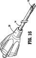
本明細書の新規な内視鏡外科用クリップ取付器が開示されている。ここで図1を参照すると、外科用クリップ取付器10が、おおまかにはハンドルアセンブリ12および内視鏡部を有しており、内視鏡部は、ハンドルアセンブリ12から遠位方向へと延びる細長い筒状部材14を備えている。ハンドルアセンブリ12は、熱可塑性材料から作られており、細長い部材は、生体適合性の材料から作られている。一実施形態においては、材料がステンレス鋼であってよく、さらにほかの実施形態においては、チタニウム材料または合金であってよい。一対のジョー16が、筒状部材14の遠位端に取り付けられている。ジョー16は、トリガ18によって操作される。トリガは、ハンドルアセンブリ12に可動に取り付けられている。
A novel endoscopic surgical clip applier is disclosed herein. Referring now to FIG. 1, a surgical clip applier 10 generally includes a
ジョー16も、ステンレス鋼、チタニウム、または適切な合金など、適切な生体適合性材料から形成されている。さらに内視鏡部は、ノブ20を有している。ノブ20は、ハンドルアセンブリ12の遠位端に回転可能に取り付けられており、細長い筒状部材14および筒状部材14に位置するジョー16に細長い筒状部材14の長手中心軸に対する360度の回転をもたらすよう、細長い筒状部材14に接続されている。クリップ取付器10の重要な様相は、後で詳しく説明されるが、ノブ20が医師の指を使用して単純に回転するために適した構成を有している点にある。
The
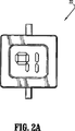
ここで図2を参照すると、内視鏡外科用クリップ取付器10が、表示装置22を有している。表示装置22は、事象の通知をもたらすためにこの技術分野において知られている任意の装置であってよい。事象とは、手術またはクリップ取付器10の動作に関するものと考えられる。好ましい実施形態において、表示装置22は、液晶表示装置であってよい。しかしながら、他の実施形態においては、表示装置22が、プラズマディスプレイ、1つ以上の発光ダイオード、ルミネセンス表示装置、多色表示装置、デジタル表示装置、アナログ表示装置、パッシブ表示装置、アクティブ表示装置、いわゆる「ねじれネマチック」表示装置、いわゆる「超ねじれネマチック」表示装置、「デュアルスキャン」表示装置、反射型表示装置、バックライト式表示装置、英数字表示装置、モノクロ表示装置、いわゆる「低温ポリシリコン薄膜トランジスタ」またはLPTS TFT表示装置、あるいは手術またはクリップ取付器10に関するパラメータ、情報、または画像を表示する他の任意の表示装置22であってよい。一実施形態においては、表示装置が液晶表示装置22、すなわち「LCD」である。LCD22は、クリップ取付器10の1つ以上の動作パラメータを医師へと表示する白黒またはカラーの表示装置であってよい。ここで図2Aを参照すると、LCD表示装置22の正面図が示されている。表示装置22が、パラメータを表示して提示している。一実施形態においては、表示されるパラメータが、残りのクリップの量、使用されたクリップの数、位置のパラメータ、使用の手術の時間、または手術についての他の任意のパラメータであってよい。LCD22は、文字、画像、またはこれらの組み合わせを表示することができる。一実施形態においては、保管の最中に電池が枯渇してしまうことがないよう、LCD22が、マイラー(Mylar)または他のポリマー絶縁材料から作られたタブを、LCD22の電池とLCD22のコンタクトとの間に配置して有することができる。タブは、タブの取り除きを可能にするため、クリップ取付器10の外へと延びることができる。ひとたび取り除かれると、タブがクリップ取付器10から引き出されて電池がLCD22の電気コンタクトに接触でき、LCD22に電力をもたらすことができる。本発明のクリップ取付器10の一実施形態においては、LCD22が、表示を拡大するレンズを有している。LCD22のレンズは、医師が遠方からでも表示を容易に読むことができるよう、表示を任意の所望の大きさに拡大することができる。次に図3を参照すると、ジョー16は、内側にただ1つの外科用クリップを収容するためのチャネル24を有している。公知のとおり、止血用のクリップを例えば体腔内に適用するために、外科用クリップを、クリップ取付器10の装填用構造によってチャネル24内に適用または配置することができる。
Referring now to FIG. 2, the endoscopic surgical clip applier 10 has a
ここで図6Aを参照すると、内視鏡外科用クリップ取付器10のハンドルアセンブリ12が、ハンドルアセンブリ12の開放された第1の側面から見て示されている。内視鏡外科用クリップ取付器10は、トリガ18を叉骨状リンク26へと接続して有している。叉骨状リンク26は、一端がトリガの溝28を取ってトリガ18へと接続され、他端が第1および第2の叉骨状部材30、32を有している部材である。第1および第2の叉骨状部材30、32が、駆動部材36を受け入れるための空間34を形成している。
Referring now to FIG. 6A, the
駆動部材36は、図示のとおりハンドルアセンブリ12内に長手方向に配置された実質的に平坦な部材であり、ジョー16への装填を行うとともに、完全に成形されたクリップを形成すべくジョー16を動作させ、その後に次のクリップの適用のために初期位置への復帰を行うため、1つ以上の駆動構造を動かすように意図されている。戻しばね38が、駆動部材36を囲むように配置されている。駆動部材36は、クリップ取付器10を動作させるべく駆動機構に接続されるとともに、トリガ18が操作されて叉骨状リンク26が駆動部材36を長手または遠位の様相に前進させた後に、戻しばね38が駆動部材36およびトリガ18を次のクリップの適用のために元の位置へと復帰させるように、適切に接続されている。
The
駆動部材36は好都合である。駆動部材36は、ひとたび駆動部材36が遠位方向への前進を開始すると、中間位置における運動を妨げることによって、開いたクリップ取付器10が完全に動作する前にトリガ18が意図せず復帰することがないようにする。駆動部材36は、ラック40を有している。ラック40は、駆動部材36の上面42に配置されている。
The
ラック40は、複数の歯44を有しており、歯44が、外科用クリップ取付器10が動作を完了する前にトリガ18および駆動部材18が意図せず復帰することがないよう、もう1つの相補的な表面と係合するように噛み合わせられている。外科用クリップ取付器10は、爪戻しばね48を備える爪46を有している。爪46は、ラック40の歯44と係合するように、爪ばね48によって付勢されている。歯44および爪46が、後述のとおりトリガ18が完全に動作するまで、トリガ18の解放を防止する。
The
次に図6Bを参照すると、クリップ取付器10が、アクチュエータ板50をさらに有している。アクチュエータ板50は、ハンドルアセンブリ12内に長手方向に配置されている。アクチュエータ板50は、駆動部材36の下方に配置され、LCDレバー52に作用可能に接続されている。
Next, referring to FIG. 6B, the clip applier 10 further includes an
ここで図6Bを参照すると、LCDレバー52は、LCD表示装置22へと作用可能に接続されるために適した構造である。レバー52が、LCD表示装置22を動作させてクリップ取付器10の1つ以上の動作パラメータを表示させることができるよう、LCD表示装置22の適切な機構またはコンタクトを動かす。一実施形態においては、アクチュエータ板50が、医師が打ち出さなければならない残りのクリップの量を表示するため、対応するLCD表示装置22の構造またはコンタクトを動かすように、LCDレバー52へと接続されている。他の実施形態においては、表示装置が、いくつかの発光ダイオード、液体プラズマディスプレイ、電子デバイスまたは表示装置、変更可能な表示装置、あるいはこれらの組み合わせであってよい。
Referring now to FIG. 6B, the
ここで図6Dを参照すると、アクチュエータ板50が、信号装置54をさらに有している。信号装置54は、アクチュエータ板50に接続され、開放クリップ取付器10が外科用クリップを打ち出した旨の音響信号をユーザへともたらすことができる装置である。信号装置54は、医師へと聴覚によるフィードバックをもたらすため、クリップ取付器10が動作すると音声を発する。他の実施形態においては、信号装置54が、特徴的な音声を発する他の電子デバイスであってよい。信号装置54は、ハンドルまたはトリガのたわみ、クリップの圧縮、クリップの装填、新たなクリップの装填、あるいはすべてのクリップの消費に応答して音声を発することができ、あるいはクリップ取付器10の事象に応じていくつかの異なる音声を発してもよい。特徴的な音声とは、所望の任意のレベルのクリック音、チャープ音、サウンド、声、録音、サウンドの組み合わせ、または任意の音波であってよい。さらに、信号装置54は、クリップ取付器10の事象に応答して通知をもたらすことができる。一実施形態においては、信号装置54が、通常の動作の際に音声を発することができ、事象が発生したときに音声の放射を止めることができる。さまざまな構成が可能であり、それらがすべて本明細書の開示の範囲に包含される。
Referring now to FIG. 6D, the
さらに図6Dを参照すると、クリップ取付器10が、ロックアウト機構56をさらに有している。ロックアウト機構56は、クリップ取付器10に収容された量のクリップが使い尽くされた場合に、医師による開放クリップ取付器10の空打ちを防止するための構造である。ロックアウト機構56は、さらに詳しく後述される様相で、トリガハンドルAの相補的な構造と係合して、トリガ18のさらなる移動を防止し、叉骨状リンク26を動作させることがないようにする。
Still referring to FIG. 6D, the clip applier 10 further includes a
次に図7を参照すると、反対側からのハンドルアセンブリ12の分解図が示されている。外科用クリップ取付器10が、実質的に「S字」形の部材であるアクチュエータ板50を有している。図7および9Aに最もよく示されているように、アクチュエータ板50は、第1の直交形状の窓60を有する第1の部位58と、第2の直交形状の窓64を有する第2の部位62とを有している。
Referring now to FIG. 7, an exploded view of the
アクチュエータ板50の第1の端部において、アクチュエータ板50が、一対の歯66を形成する丸め部または湾曲部を有している。反対側の第2の端部68は、突起70を有している。突起70が、LCDレバー52の溝72に係合する。アクチュエータ板50を叉骨状リンク26を介して駆動部材36へと接続するため、ピン74が、第1の直交形状の窓60を通って配置されている。また、このやり方で、トリガ18が駆動部材36を遠位方向に動かすとき、接続ピン74が第1の窓60を横切って動かされ、ひとたび接続ピン74が第1の直交形状の窓60の遠位側の外縁76に接すると、アクチュエータ板50が同様の様相で遠位側へと動かされる。
At the first end of the
再び図7を参照し、さらに図9Bを参照すると、クリップ取付器10が、可聴クリックレバー78を備える信号装置54をさらに有している。可聴クリックレバー78は、アクチュエータ板50の反対側に位置しており、第2の窓64を通過している。信号装置54は、可聴クリックばね80をさらに有している。さらに信号装置54は、アクチュエータ板50によって長手方向に遠位側へと動かされたとき、相補的であるハンドル表面へと回転して向きを変える可聴クリックレバー78を有している。アクチュエータ板50が、側面82(図9Aに示されている)を有する第2の窓64を動かし、側面82が可聴クリックレバー78の柱77(図9B)を偏向させて、レバー78をハウジングの表面のリブに接触させる。この接触によって、クリップ取付器10が外科用クリップを打ち出した旨の医師への可聴警報または音響信号が生成される。
Referring again to FIG. 7 and further to FIG. 9B, the clip applier 10 further includes a
図7を参照すると、クリップ取付器10が、第1のレバー部84と、穴86と、溝72を有する湾曲部材88とを備える回転可能な部材であるLCDレバー52(図9Cに最もよく示されている)をさらに有している。溝72は、アクチュエータ板50の突起70と取り合い、図7に示した第1のハンドルハウジング部94と取り合うペグ92を有している。
Referring to FIG. 7, the clip mounter 10 is an LCD lever 52 (best shown in FIG. 9C), which is a rotatable member comprising a
図7を参照すると、LCD22が、LCDレンズ98を備え、LCD22へと接続されたLCDカウンタ・コンタクト板100を備えているLCDユニット96を有している。LCDカウンタ・コンタクト板100は、駆動されたときに、LCD表示装置22を先のパラメータから現在のパラメータ(一実施形態においては、クリップ取付器10に残っているクリップの量など)へと切り替える。
Referring to FIG. 7, the
クリップ取付器10は、爪ばね48を備える爪46をさらに有している。爪46は、ラック40の歯44に係合する端部を有している。
The clip applier 10 further includes a
図7を参照すると、クリップ取付器10が、ロックアウト機構56をさらに有しており、ロックアウト機構56は、アーム104とアーム104に接続された爪106とを備える第1の回転可能部材またはシャフト102を有している。第1の回転可能部材102は、おおむね円柱形の形状であり、ばね105を介してハンドルの相補的な表面へと接続されている。一実施形態においては、第1の回転可能部材102が、ロックアウト・アームである。
Referring to FIG. 7, the clip applier 10 further includes a
さらにロックアウト機構56は、第1の回転可能部材102からオフセットされた第2の回転可能部材112を有している。第2の回転可能部材112は、一実施形態においては、ロックアウト・ホイールであって、おおむね円形の構成を有している。ロックアウト・ホイール112の内周114は、内周を巡って離間した複数の歯116を有している。ロックアウト・ホイール112は、中心の柱118を有しており、柱118が、第1のアーム122を自身に接続して有している第3の回転可能部材120へと穴を貫いて接続され、さらにハンドル部12へと接続される。トリガ18が引かれるとき、ハンドル部12へと接続された第1の回転可能部材102と、トリガ18へと接続された第3の回転可能部材120との間に、相対運動が存在する。したがって、ロックアウト・ホイール112は、中心の柱118がハンドル部12へと接続されているため、所定の量だけ回転することになる。ロックアウト・ホイール112が回転すると、第1の回転可能部材102の爪106が進められる。クリップを打ち出すべくトリガ18が引かれるたびに、爪106は、本明細書において説明した好都合なラチェット機構ゆえ、複数の歯116の間の長さを1単位として移動して、複数の歯116に位置する。ロックアウト・ホイール112は、ロックアウト・ホイール112の外周部分に位置する直交形状の切り欠き110である逃げノッチ110を有している。逃げノッチ110により、第1の回転可能部材102の爪106が、ロックアウト・ホイール112の内側の位置または内周114から逃げノッチ110を通って外へと移動でき、参照符号Aで示されているトリガの相補的な構造に係合し、トリガ18のさらなる動きを防止し、叉骨状リンク26が操作されないようにすることができる。
The
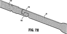
クリップ取付器は、シャフトアセンブリ124を有するノブ20をさらに有している。スピンドル・リンク126が、図7Aに示したスピンドル128につながっている。ここで図7Gおよび図7Hを参照すると、ドライバ棒36が、スピンドル・リンク126につながっている。スピンドル・リンク126は、ジョー16と反対の近位側に、スピンドル・リンク・フック185を有している。ドライバ棒36が、角を成したフック部材186を有している。角を成したフック部材186は、ドライバ棒36の遠位側184に位置している。ここで、図7Gの線7H−7Hに沿った断面図を参照すると、ドライバ棒36の角を成したフック部材186が、スピンドル・リンク・フック185と対をなしている。したがって、図示のとおり、駆動部材36がスピンドル・リンク126を遠位方向に進めることができる。ここで図7Aを再び参照すると、スピンドル・リンク126の(スピンドル・リンク・フック185に対して)反対側の遠位端が、スピンドル128への円形のボス接続部188につながっている。このやり方で、スピンドル128を、参照用の矢印Bによって示されているとおりスピンドル・リンク126と別個独立に回転させることができる。
The clip applier further includes a
ここで図7Bを参照すると、図5の線7B−7Bに沿ったノブ20の断面図が示されている。ノブ20は、ノブ20の穴または内腔134において互いに接続された第1の本体半分130および第2の本体半分132を有している。
Referring now to FIG. 7B, a cross-sectional view of the
ここで図7Cを参照すると、ノブ20が、ノブ20とつながる平たい先細りの表面138を有しているノブハウジング136につながる。再び図7Bおよび7Cを参照すると、ノブ20が、自身を貫く内腔134を有している。ノブハウジング136は、外側筒状部材142をさらに有しており、第1の溝144および第2の溝146が、筒状部材142を貫いて配置され、さらに外側筒状部材142は、両側面のそれぞれに「C字」形の第1の開口148および「C字」形の第2の開口150を有している。
Referring now to FIG. 7C, the
ノブハウジング136が、医師が人差し指を使用してノブ20の側面に触れ、ノブ20を時計方向または反時計方向に回転させることによって、一方の手だけで筒状部材14を回転させることができるようにするために適している細長い円柱形の形状を有しているため、ノブハウジング136がきわめて好都合であることは明らかである。これは、一部の医師が好まない筒状部材14を回転させるための両手操作を避けることができ、より人間工学的な筒状部材14の操作または回転を提供する。
The
図7Cを参照すると、ノブ20は、内腔134の内表面に、内腔134内へと外表面と反対方向に延び、ノブハウジング136の第1の「C字」形の開口148および第2の「C字」形の開口150とそれぞれ対をなす第1のアーム152および第2のアーム154を有している。
Referring to FIG. 7C, the
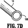
再び図7Bおよび7Eを参照すると、外側の筒14が、第1の穴158’と第2の穴160’とを備えるブシュ156をさらに有しており、第1のピン162が第1の穴158’を貫いて延び、第2のピン164が第2の穴160’を貫いて延びている。ここで図7Eを参照すると、ブシュ156が、ブシュ156の外周の位置から延びるタブ166をさらに有している。タブ166が、ノブハウジング136の切り欠きに係合する。さらにブシュ156は、第2のタブ166’を有している。第2のタブ166’も、筒状部材14の回転のために図7Dに示した筒状部材14の切り欠き168に係合する。これら種々の構成部品を動作させるため、スピンドル128が、筒状部材14を通って長手方向に運動するように取り付けられている。
Referring again to FIGS. 7B and 7E, the
次に図8を参照すると、すでに説明した爪46の斜視図が示されている。爪46は、三角形形状の部材であって貫通穴169が配置されている。さらに爪46は、上面176に角を成す複数の表面170、172、174を有し、反対側の下側180には、図6Dの駆動部材36に示したようなラック40の歯44に係合するため、歯係合構造178を有している。図示のとおり、駆動部材36は、図9Dの叉骨状リンク26と対をなすための穴182を有するとともに、第1の側181および反対側の第2の側184を有しており、第2の側184が、スピンドル128を遠位方向に進めるための角を成すフック部材186を備えている。
Referring now to FIG. 8, there is shown a perspective view of the
次に図9Dを参照すると、叉骨状リンク26が、ピン74によって、アクチュエータ板50の図9Aの第1の細長い形状の窓60を通って駆動部材36へと接続される。アクチュエータ板50は、突起70によって図9CのLCDレバー52の溝72につながり、さらにアクチュエータ板50は、図9Bに示した信号装置54に接続されている。信号装置54は、ハンドルハウジングと対をなすための穴188を有している。可聴クリックレバー78が、弾性表面191を備える球状の端部190を有しており、クリックレバー78が回転すると、球状の端部191が他のハンドル表面またはリブに鋭く衝突し、外科用クリップが打ち出された旨を知らせるべくハンドルアセンブリ12から音波を生じさせることができる。信号装置54は、図9Aの第2の窓64につながる柱77をさらに有しており、アクチュエータ板50が遠位方向に移動するとき、柱77がレバー54を回転させる。
Referring now to FIG. 9D, the rib-
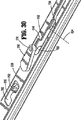
次に図10を参照すると、開放クリップ取付器10の内視鏡部16の種々の構成部品の分解図が示されている。クリップ取付器10は、外側の筒状部材14を有している。外側の筒状部材14は、大まかには、第1の端部192および第2の端部194を有する円筒形の部材である。第1の端部192は、内腔を通じてスピンドル・リンク126へと接続される。すでに述べたように、スピンドル・リンク126は、スピンドル128へと接続される。外側筒14は、スピンドル128の周囲に配置される。クリップ取付器10は、ピン162、164を有している。ピン162および164は、ブシュ156の側面を貫いて延びている。ピン162、164は、ブシュ156に対して内向きに付勢されて、外側の筒状部材14に接触している。クリップ取付器10は、ブシュ156の前進を防止するためのばね196をさらに有している。ばね196は、ノブ20へとつながるノブハウジング136に配置されている。
Referring now to FIG. 10, an exploded view of the various components of the
クリップ取付器10は、細長い筒状部材14の内腔を通って配置された噛み合いスピンドル・リンク126をさらに有している。本発明のクリップ取付器は、クリップ取付器のいくつかの異なる機能を実行するために、いくつかの異なるアセンブリを有している。クリップ取付器10は、駆動機構を動作させることによってジョー16を閉じて完全に成形されたクリップを形成するため、筒状部材14を通って移動するようにスピンドル機構128を有している。さらにクリップ取付器10は、ウェッジ機能のための機構を有しており、このウェッジ機能のための機構は、ジョー16への装填のためにジョー16を離間した状態に維持するために設けられており、ひとたびジョー16への装填が行われたならば引き込まれる。また、クリップ取付器10は、クリップをジョー16へと供給する供給機能を有している。さらにクリップ取付器は、クリップ収容機能、および収容したクリップを後の装填のために付勢するクリップフォロワ機能を有している。
The clip applier 10 further includes a
種々の構成部品を動作させるため、図10においてノブ20の上方に示されている操作機構またはスピンドル128が設けられている。スピンドル128は、細長い筒状部材14を通って長手方向に遠位側および近位側へと移動するように取り付けられている。スピンドル128は、駆動バー200およびスライダジョイント202を備えるカム機構を遠位端204に有しており、スライダジョイント202が、カム面同士を選択的に係合させてジョー16を外科用クリップの周囲へと閉じるため、スピンドル128の遠位端204から延びている。
In order to operate the various components, an operating mechanism or
さらに、スピンドル128は、スライダジョイント202上のラッチ部材206およびスピンドル128上のカムリンク208を有している。ラッチ部材206は、スピンドル128へと向かう方向にカムとして動作する。ラッチ部材20は、スピンドル128の対応する溝へと進入してカムとして動作する。ラッチ部材206は、駆動バー200の遠位方向への移動を許す。さらにラッチ部材206は、スピンドル128と駆動バー200との間の所定の残存間隔を減らすべくスピンドル128が遠位方向に移動するとき、駆動バー200がジョー16を動作させることがないようにする。さらにスピンドル128は、遠位方向への前進の際に他の構造をスピンドル128の長手方向軸に対して直角な方向に移動させるため、カム造作210または張り出し縁を有している。
In addition, the
クリップ取付器10は、所望の組織への適用のために、1つまたは複数の外科用クリップ300を保持している。クリップ取付器10は、いくつかの外科用クリップ300を保持するために細長いクリップチャネル部材302を有しおり、これらの外科用クリップ300が、クリップチャネル部材302の上方に整列した様相で示されている。細長いクリップチャネル部材302は、細長い筒状部材14に対して長手方向に移動することはない。クリップ取付器10は、フォロワ306をフォロワばね308に接続して有している。フォロワばね308が、クリップをクリップチャネル部材302内で遠位方向に押し付けている。また、クリップ取付器10は、フォロワ306およびフォロワばね308ならびにクリップ300をクリップチャネル部材302内に保持して遠位方向へと案内するため、クリップチャネル部材302へと重なるチャネルカバー310を有している。さらにクリップ取付器10は、クリップ300を案内してクリップチャネル部材302を通ってジョー16の間のチャネル24へと移動させるためのノーズ312を有している。
Clip applier 10 holds one or more
さらにクリップ取付器10は、ジョー16の間のチャネル24へとクリップ300を供給するための供給バー400を有している。さらに供給バー400は、相対運動を提供する。ここでクリップチャネル部材302の遠位部分を参照すると、供給バー400が示されている。供給バー400は、この遠位側の位置において、クリップ300をジョー16の間のチャネル24へと前進させる。ここで、ジョー16と反対側の近位側の位置を参照すると、供給バー400が押しばね402(図10)を有している。押しばね402が、供給バー400を長手の遠位方向に付勢している。押しばね402は、トリップブロック406の切り欠き404の下方の相補的な位置に配置されている。トリップブロック406は、トリップブロック406の遠位側において、クリップチャネルカバー部材304に隣接している。供給バー400が、トリップブロック406の上方に示されている。供給バー400は、フック408を有している。フック408は、トリップブロック406の切り欠き404に係合する。さらにクリップ取付器10は、案内ピン401を有している。案内ピン401は、押しばね402を通って配置され、押しばね402を整列させるために必要とされている。フック408は、トリップブロック406の下方で案内ピン401および押しばね402に係合する。このやり方で、フック408が、案内ピン401に係合すべく切り欠き404を通って配置される。押しばね402および案内ピン401が供給バー400を付勢し、供給バー400を遠位方向に進めることができるようにしている。さらに、案内ピン401が押しばね402を通って配置されることで、自己完結のアセンブリを可能にしている。スピンドル128によって押し器400を前進させるため、スピンドル128は、トリップレバー500および付勢ばね502を有している。トリップレバー500は、外科用クリップ300をジョー16の間のクリップチャネル24へと遠位方向に前進させるため、供給バー400に係合している。
The clip applier 10 further includes a
さらにクリップ取付器10は、ウェッジプレートばね602を備えるウェッジプレート600を有している。ウェッジプレート600は、複数の直交形状の貫通窓604を有する平坦な棒状の部材である。ウェッジプレートばね602は、ウェッジプレート600のラッチ開口608の舌606の周囲に位置している。ウェッジプレートばね602は、ウェッジプレート600を、クリップ装填のためにジョー16を広げるべく遠位方向へと進められた後に、遠位側の位置から近位側の位置へと引き込むことができるようにしている。また、ウェッジプレート600は、窓604と舌606との間に位置する「C字」形の窓610を有している。
Furthermore, the clip applier 10 has a
さらにクリップ取付器10は、フィラー部品700を有している。フィラー部品700は、回転可能部材702およびばね棒部材704を有している。ばね棒部材704は、フィラー部品700に配された開口706に位置している。回転可能部材702は、或る特定の範囲の運動が可能であり、第1の近位端708および第1の端部708と反対側の第2の遠位端710を有している。回転可能部材702の運動の範囲は、任意の比較的わずかな範囲または比較的大きな範囲の回転または運動であってよい。本発明のクリップ取付器10は、いかなる様相でも、特定の角度の回転に限定されず、円形、楕円形、または任意の幾何学的回転パターン、原点、軸、座標、あるいは運動などといった特定の運動の様相には限定されない。さらには、代案として、部材702が単純に任意の平面内を運動してもよく、あるいはこの技術分野において公知の他の不規則な様相で運動してもよい。さまざまな構成が可能であり、本明細書の開示の範囲に包含される。
Furthermore, the clip applier 10 has a
さらに、クリップ取付器10は、ジョー16を有している。ジョー16は、第1のジョー部材16aおよび第2のジョー部材16bで製作されている。第1のジョー部材16aと第2のジョー部材16bとの間が、クリップチャネル24である。理解されるとおり、ジョー部材16aおよび16bは、チャネル24内で完全に成形されたクリップを形成すべく閉鎖および圧縮を行うため、内側に向かって運動することができる。さらにジョー16は、外表面に第1の隆起カム面212および第2の隆起カム面214を有している。第1の隆起カム面212および第2の隆起カム面214は、ジョー16の閉鎖および圧縮のため、他の駆動カム面と選択的に係合することができる。
Further, the clip applier 10 has a
次に図10Aを参照すると、供給バー400の図が示されている。供給バー400は、トリップレバー500との係合のための矩形の窓410を有する長手方向の部材である。供給バー400は、フック408を供給バーの下面412に配置してさらに有している。さらに供給バー400は、クリップ搬送チャネル302内の外科用クリップ300に係合してこれを操作するため、押し器414を遠位端に有している。
Referring now to FIG. 10A, a diagram of
図10Bに示されているように、供給バー400は、クリップ搬送チャネル302内でクリップ300を押して遠位方向に動かすため、クリップ搬送チャネル302内をスライドするフォロワ306と協働する。図10Cおよび10Dには、トリップブロック406が、第1の向きおよび反対の第2の向きの両者で示されている。
As shown in FIG. 10B, the
すでに述べたように、トリップブロック406は、自身に切り欠き404を有しており、さらに第1および第2の歯付き部材420を形成する斜めの表面を有している。第1および第2の歯付き部材420のそれぞれは、後述するトリップレバー500の対応する表面との係合のためのものである。図10Cおよび10Dのトリップブロック406の切り欠き404は、図10Aに示した供給バー400のフック408を受け入れるためのものである。トリップレバー500を図10Aに示した供給バーの窓410から切り離すため、図10Cおよび10Dのトリップブロック406が、図10に示したトリップレバー500に係合する第1および第2の歯付き部材420を有している。第1および第2の歯付き部材420が、トリップレバー500を図10Aの窓410から切り離す。
As already mentioned, the
次に図10E〜10Fを参照すると、スピンドル128が示されている。図10Fを参照すると、スピンドル128は、トリップレバー500を収容するため、およびトリップレバー付勢ばね502を収容するために、第1の直交する空洞222および第2の直交形状の空洞224を有している。第1の直交する空洞222は、トリップレバー500を第1の位置から第2の回転可能位置へと枢動させることができるよう、枢支ボス226(図10F)を有している。トリップレバー付勢ばね502は、第2の空洞224に位置している。図10に示したばね502が、製造を容易にするため付勢ばね502にボスまたは部材を接続することなく、第2の空洞224に位置している。次に、図10Gに示したスピンドル128の反対側の位置を参照すると、さらにスピンドル128が、カム造作210を備える溝209と、カムリンク208を収容して遠位方向へと動かすことができるさらなる空洞228とを有している。スピンドル128が、さらに詳しく後述するように、クリップ取付器10の駆動部品と係合すべく遠位方向に進められる。
Referring now to FIGS. 10E-10F, the
図12を参照すると、トリップレバー付勢ばね502が、破線で示されているとおりにスピンドル128の第2の空洞224と噛み合う第1および第2の弓状端504、506を有している。トリップレバー付勢ばね502は、第2の部材508をさらに有している。第2の部材508は、スピンドル128の通常の表面と反対に外向きに付勢している。第2の部材508は、トリップレバー500に接触している。トリップレバー500は、スピンドル128の枢支ボス226に回転運動可能に係合するC字形の端部510、およびトリップレバー付勢ばね502の上方へと延びるもう1つの端部512を有している。トリップレバー500を供給バー400から切り離すため、トリップブロック406が、すでに述べたようにトリップレバー500に選択的に係合して、トリップレバー500を供給バー400の窓410から切り離すことができる斜めの表面または歯付きの表面420を有している。
Referring to FIG. 12, the trip
図11を参照すると、スピンドル128は、ウェッジプレート600と係合できるカムリンク208を有している。カムリンク208は、カムリンク208から延びるカムリンクボス230を有している。カムリンク208は、ストロークの際にスピンドル128によって遠位方向に動かされる。
Referring to FIG. 11, the
スライダジョイント202の近位端248が、溝250においてスピンドル128へと接続される。スライダジョイント202は、反対側に「T字」形の端部252を有している。T字形の端部252は、駆動バー200へと接続されている。スライダジョイント202はラッチ部材206を有しているが、ラッチ部材206は、他の部材と連絡してスライダジョイント202が駆動バー200を前進させることがないようにし、クリップ300をジョー16へと供給する初期のストロークの際に駆動バー200のカム面256がジョー16を縮めることがないようにするため、スライダジョイント202の開口254を通って移動するように配置されたリンクである。
The
図13〜13Aを参照すると、ウェッジプレート600が示されている。ウェッジプレート600は、ウェッジプレートばね602を有している。ウェッジプレートばね602は、ウェッジプレート600の付勢装置をもたらしている。ウェッジプレート600が、ウェッジプレートばね602によって付勢される。ばね602は、破線で示されているように舌606を囲んでいる。さらに、ウェッジプレート600は、「C字」形の開口または貫通窓610を有している。
Referring to FIGS. 13-13A, a
「C字」形の開口または窓610は、フィラー部品700の回転可能部材702と選択的に係合する。また、ウェッジプレート600は、カム面614を有するカムスロットまたはカム溝612を有している。カムスロットまたはカム溝612は、ウェッジプレート600の運動を制御する所定の形状を有している。カムスロットまたはカム溝612は、スピンドル128のカムリンク208と協働し、ウェッジプレート600を遠位方向に移動させ、装填のためにジョー16をわずかに広げる。また、カム面614は、筒状部材14内でウェッジプレート600を近位方向に移動させるべくカムリンク208と協働し、ひとたび装填されたチャネル24内のクリップ300をジョー16によって圧縮することができる。
A “C” shaped opening or
ウェッジプレート600は、装填のためにジョー16を広げるため、丸みのある遠位端616を有している。さらにウェッジプレート600は、ウェッジプレート600の引き込みを制限するため、近位側の窓622を有している。
The
図14および14Aを参照すると、フィラー部品700が第1の向きで示されており、さらに図15に第2の反対の向きで示されている。フィラー部品700は、C字形の端部712および回転可能部材702を有しており、回転可能部材702は、フィラー部品700の真ん中の部分のピン716によって接続される穴714を有している。回転可能部材702は、ウェッジプレート600の運動を制御するため、ウェッジプレート600の対応する構造につながる。フィラー部品700の反対側には、開口718が位置している。回転可能部材702は、第1の端部708および反対側の第2の端部710を有している。第1の端部708が、ばね棒部材704との接触によって付勢されており、すなわちばね棒部材704が、ばね棒部材704と回転可能部材702との間の付勢作用を可能にしている。
Referring to FIGS. 14 and 14A,
さらにフィラー部品700は、フィラー部品カム溝720を有している(図15に示されている)。フィラー部品カム溝720は、カムリンク208のボス230を受け入れるように構成されている。さらにフィラー部品700は、ウェッジプレート600の近位側への引き込みを制限するためのストッパ722を有しており、さらに部材724を有している。部材724は、ウェッジプレートの舌606およびばね602と係合する。
Further, the
次に図16および17を参照すると、スピンドル128および関連の駆動部品が示されている。ブシュ156が、ジョー16の過剰ストローク状態を可能にするため、図17に示すようにばね196を自身に接続して有している。ばね196が、ジョー16へと過剰な力が加わることがないようにしている。
Referring now to FIGS. 16 and 17, the
次に図18〜20を参照すると、スピンドル128が示されている。供給バー400が、押し器414をクリップ300と係合すべくクリップ搬送チャネル302内へと延ばすよう、下向き(図19)の様相で延びている。押し器414が、クリップ搬送チャネル部材302内のクリップ300のそれぞれを、ジョー16の間のチャネル24へと前進させる。図19に示したクリップ取付器10の遠位領域を参照すると、クリップ取付器10が、周囲に位置する組織のストッパとして機能するノーズ312の周囲の「C字」形の部材416を有している。すでに述べたように、ノーズ312は、ただ1つのクリップがチャネル24へと導入されるようにする助けとなる。さらにクリップ取付器10は、いくつかのT字形のタブ418を有している。タブ418は、クリップ搬送チャネル302、チャネルカバー310、およびノーズ312を一体のユニットとして一体に保持するためのものである。
18-20, the
ジョー16とは反対側の図20に示した近位側を参照すると、スピンドル128がトリップレバー500を有している。トリップレバー500は、供給バー400を(筒状部材14を通って)遠位方向に前進させ、ジョー16の間のチャネル24へとクリップ300を導入すべく押し器414を遠位方向に移動させるため、図示のとおり供給バー400の窓410を通って延びている。
Referring to the proximal side shown in FIG. 20 opposite the
図21〜24が、クリップ搬送チャネル302内の複数のクリップ300を示している。クリップ搬送チャネル302は、クリップ搬送チャネル302内のクリップ300を支持および保持するため、自身の周囲に湾曲した複数のフィンガ420を有している(図23)。図24を参照すると、途中まで組み立てられたフォロワ306の斜視図が示されている。フォロワ306は、フォロワ306を遠位方向に付勢して前進させるフォロワばね308と一緒に、クリップ搬送チャネル302内に配置されている。フォロワばね308が、クリップチャネル302内のクリップ300に力を加える。図21に示されているとおり、クリップ取付器10は、アセンブリを一体に保つため、クリップチャネル302上に複数の「T字」形のタブ418を有している。
FIGS. 21-24 show a plurality of
次に図25を参照すると、クリップ取付器10は、スピンドル128上にトリップレバー500を有している。トリップレバー500は、スピンドルの上側と反対にたわむように付勢されたT字形の部材であり、すでに述べたようにトリップレバーばね502によって付勢されている。次に図26および27を参照すると、駆動バー200が、組み立てられた位置においてウェッジプレート600またはジョー16の上に位置するように配置され、ジョー16を閉じてチャネル24内のクリップ300を圧縮するため、第1および第2の隆起カム面212および214の上方を遠位方向に移動する。
Next, referring to FIG. 25, the clip applier 10 has a
次に図28〜30を参照し、トリップブロック406、ウェッジプレート600、およびフィラー部品700の相互の組み立て部分を説明する。ウェッジプレート600が、スピンドル128上に配置されて示されている。
Next, referring to FIGS. 28 to 30, the assembled parts of the
図29および30を参照すると、クリップ取付器10が、フィラー部品700の移動を制限するためのストッパ部材618を有している。フィラー部材700は、この図においてウェッジプレート600の真下に配置されている。ウェッジプレート600は、「C字」形の窓610を有しており、回転可能部材702が、「C字」形の窓610を通って配置されている。ウェッジプレート600は、カム面614を有するカム溝612をさらに有している。カムリンク208が、この図においてウェッジプレート600の上部に配置されている。カムリンク208は、ウェッジプレート600のカム溝612と取り合うカムリンクボス230を有している。
Referring to FIGS. 29 and 30, the clip applier 10 has a
図29を参照すると、ウェッジプレート600が、舌606の周囲にウェッジプレートばね602を有し、さらに舌606の周囲にフィラー部品700の部材724を有している。このやり方で、舌606がフィラー部品700に対して遠位方向に移動するとき、ウェッジプレート600が近位方向に復帰するように付勢される。さらにフィラー部品700は、フィラー部品700に対するウェッジプレート600の遠位方向への移動をさらに制限するため、ウェッジプレート600の近位側の窓622にストッパ722を有している。
Referring to FIG. 29, the
さらに、カムリンク208が、カム溝612内を遠位方向に駆動されるように構成されている。さらには、カムリンク208は、この図においてウェッジプレート600の真下に示されているフィラー部品のカム溝720に乗るように構成されている。
Further, the
カムリンク208がスピンドル128の前進から遠位方向に駆動されるとき、カムリンクボス230がウェッジプレート600のカム面614に係合し、ウェッジプレート600を遠位方向に駆動する。ウェッジプレート600は、図30に示した境界線624に達するまで遠位方向に進む。境界線624において、カムリンクボス231が、図30に示したフィラー部品700の切り離しのカム面726に係合する。
When the
切り離しのカム面726は、フィラー部品のカム溝720内の造作である。当然ながら、切り離しのカム面726は、カム作用によってカムリンクボス231をカム溝612のカム面614との係合から解放する。この境界点624において、ウェッジプレート600はもはや遠位方向には移動しない。
The decoupled
次に図31〜34を参照し、ウェッジプレート600、フィラー部品700、および駆動バー200の種々の組み立て部分を説明する。ウェッジプレート600が、スピンドル128上に配置されたフィラー部品700の上方に位置している。ジョー16は、一対の可撓レグ17a、17bを有している。レグ17a、17bは、基部部材17cへと固定されている。ジョー16は、可撓レグ17a、17bに対して遠位端に位置している。一対の固定アーム19a、19bが、基部17cから延伸して一対のタブ21a、21bを終端としている。タブ21a、21bは、ジョー16を細長い外側筒14へと固定するため、細長い外側筒14の一対の穴(図示されていない)に係合する。
The various assembled parts of the
フィラー部品700は、ジョー16に対して直ぐ近位側に配置されており、細長い外側筒14に対して移動することはない。ここで図31〜33を参照すると、駆動バー200の上方に配置され、スピンドル128上に位置しているウェッジ部品600の図が示されている。ウェッジプレート600は、図31のフィラー部品700の下方に位置している。ウェッジプレート600は、図33にジョーを取り除いて最もよく示されている。ジョー16は、ウェッジプレート600の丸みを帯びた遠位端616を受け入れるように構成されている。丸みを帯びた遠位端616が、最初はジョー16を広げている。丸みを帯びた遠位端616が、ジョー16のチャネル24へとクリップ300を挿入する際に、ジョー16を広げられて整列した構成に維持している。
The
ウェッジプレート600が、ジョー16を広げられた状態に維持する丸みを帯びた遠位端616を有しており、丸みを帯びた遠位端616がジョー16のたわみまたはトルクを防止していることが明らかである。ジョー16のそれぞれは、容易かつ繰り返し可能な様相で図32に示すとおりジョー16の間にウェッジプレート600の丸みを帯びた遠位端616を案内するカム造作23a、23bを有している。カム造作23a、23bは、図示のとおりジョー16の内表面に位置しており、第1の隆起カム面212と第2の隆起カム面214との間に位置している。
The
図34を参照すると、スライダジョイント202および駆動バー200を有するスピンドル128の図が示されており、説明の目的のためウェッジプレート600は取り除かれている。駆動バー200の遠位端が、駆動カム面256を有している。駆動カム面256は、ジョー16に対する駆動バー200の遠位方向の移動に応答し、ジョー16の第1および第2の隆起カム面212、214(図32)の上方を移動して、これらのカム面と協働する。
Referring to FIG. 34, a diagram of a
駆動バー200の近位端を参照すると、駆動バー200が、スライダジョイント202に接続されている。スライダジョイント202は、図34に示されているように複数のラッチ引き込み具158、160を有している。ラッチ引き込み具158、160は、スライダジョイント202から直角に延びており、図33に示したウェッジプレート600の窓604、604を通って延びるように構成されている。これらのラッチ引き込み具158、160は、図33に示すとおりジョー16に対するスライダジョイント202の引き込みおよび遠位方向への移動を制限する。本発明のクリップ取付器10の一実施形態においては、ラッチ引き込み具158が引っ込む一方で、ラッチ引き込み具160が移動を制限する。あるいは、ラッチ引き込み具160が引っ込む一方で、ラッチ引き込み具158が移動を制限できる。他の実施形態においては、ラッチ引き込み具158および160のそれぞれを、移動の制限の機能と引き込みの機能との間で切り替え可能である。さらに他の実施形態においては、3つ以上のラッチ引き込み具158、160を設けてもよい。さまざまな構成が可能であり、本明細書の開示の範囲に包含される。
Referring to the proximal end of
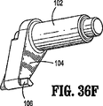
次に、血管など、対象とする組織の周囲にクリップ300を圧着するための外科用クリップ取付器10の動作について説明する。ここで図35および図36を参照すると、トリガ18が押し込まれていない状態で示されており、駆動部材36が、ばね38によって付勢されて元の位置に位置している。
Next, the operation of the surgical clip applier 10 for crimping the
図36Aを参照すると、外科用クリップ取付器10のロックアウト機構56が、元の初期の位置に示されている。図36Aに示されているように、第3の回転可能部材120のアーム122が、図36Aに示すとおりハンドルアセンブリ12の溝121に位置する部位を有している。第3の回転可能部材120は、柱118を介してロックアウト・ホイール112と対をなしている。一実施形態においては、第3の回転可能部材120が、インデクサー・ホイールである。
Referring to FIG. 36A, the
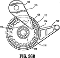
図36Bに示した反対側の図を参照すると、ロックアウト・ホイール112の内周114が、複数の歯116および逃げノッチ110を有している。逃げノッチ110は、内周114を巡った或る位置に配置されている。アーム104および爪106を有する第1の回転可能部材102が、ロックアウト・ホイール112からオフセットされ、クリップ取付器10の作動時に爪106が歯116に選択的に係合するように配置されている。
Referring to the opposite view shown in FIG. 36B, the
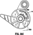
トリガ18が引かれた後、第1の回転可能部材102は、爪106が歯116のうちの他の歯に係合するように押し付けられるよう、半径方向に進められる。図36C〜36Eを参照すると、ロックアウト・ホイール112が、最後のクリップが打ち出されたときに爪106が逃げノッチ110に整列し、爪106が逃げノッチ110へと進入してロックアウト・ホイール112から解放されるよう、クリップ搬送チャネル302内のクリップの数に対して相補的である所定の数の歯116を有している。ここで図36cおよび36d、ならびに図36F〜36Iを参照すると、さらにロックアウト機構56が、ラチェットアーム650と複数のラチェット歯652とを備えるラチェット機構を有している。第3の回転可能部材120のラチェットアーム650が、ラチェット歯652に係合し、トリガ18の動作に応答してロックアウト・ホイール112を時計方向に回転させるように設計されている。トリガ18が放されると、その後にラチェットアーム650が、反対の半径方向に回転させられてラチェット歯のそれぞれの上方を移動し、したがって爪106の半径方向の前進を妨げることなく、各クリップ300が打ち出された後にラチェットアーム650が元の位置へと復帰すべく反時計方向に回転できる。
After the
図37〜42に最もよく示されているように、図38を参照すると、打ち出し前の状態において、トリップレバー500が、スピンドル128によって保持されている。トリップレバー500は、トリップレバーばね502によって付勢されている。また、トリップレバー500は、供給バー400の近位側の窓410に接触している。トリップブロック406は、トリップレバー500に対して遠位側の位置にある。
As best shown in FIGS. 37-42, referring to FIG. 38, the
図39を参照すると、クリップ300を遠位方向に付勢するため、フォロワ306がフォロワばね408によって付勢されて示されている。
Referring to FIG. 39, a
ここで図40を参照すると、スピンドル128の他の断面図が示されており、カムリンク208およびウェッジプレート600がスピンドル128上に位置している。スライダジョイント202が、ラチェット部材206をスライダジョイント202に位置させつつ、ウェッジプレート600の下方に配置されている。スピンドル128が、カムリンク208上のカムリンクボス230がウェッジプレート600のカム溝612に係合するよう、カムリンク208を或る初期の距離だけ遠位方向に駆動する。
Referring now to FIG. 40, another cross-sectional view of the
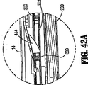
図41および41Aを参照すると、フィラー部品700を有する外側筒14の他の断面図が示されている。ウェッジプレート600が、回転可能部材702を間に延在させつつフィラー部品700の下方に配置されている。
Referring to FIGS. 41 and 41A, another cross-sectional view of the
ウェッジプレート700は、開口706内に配置されたばね棒部材704を有している。ばね棒部材704は、回転可能部材702を付勢しており、自由端においてたわむことができる。回転可能部材702は、破線で示したフィラー部品700の真下のスピンドル128のカム造作210に対し、遠位側に配置されている。ひとたび遠位方向に駆動されると、スピンドル128が前進する。スピンドル128が、カム造作210を前進させる。カム造作210は、遠位方向へと駆動され、回転可能部材702を時計方向の様相で偏向させる。
The
図41Bを参照すると、スピンドル128の断面図が示されており、図41の線41B−41Bに沿った種々の構成部品が示されている。クリップ300が、クリップチャネル302に位置し、上側に供給バー400を有している。ウェッジプレート600が、図示のとおりフィラー部品700の真下、かつスピンドル128の上方に配置されている。クリップチャネルカバー310が、クリップチャネル302の上方に配置されている。
Referring to FIG. 41B, a cross-sectional view of the
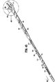
押し器414が、図42Aに示されているようにクリップ300のそれぞれをクリップチャネル24へと前進させる。図42には、打ち出し前の状態におけるスピンドル128が示されている。スピンドル128は、スライダジョイント202に接続すべく配置されている。クリップ取付器10の作動時、スピンドル128が遠位方向に移動する。所定の距離において、ラッチ部材206がカム作用によって機械的に押し下げられ、図73に示した参照用の矢印Lの方向にスピンドル128の溝250(図11に最もよく示されている)に係合する。これにより、スライダジョイント202が、駆動バー200と一緒に遠位方向に(駆動されたときに)移動することができる。これにより、駆動バー200が、ジョー16をジョー16の間のチャネル24に配置されたクリップ300の周囲へと閉じるため、該当の表面に係合できる。
A
次に図43を参照すると、当初の最も近位側の位置にあるウェッジプレート600およびジョー16の斜視図が示されている。ウェッジプレート600は、窓604内かつ舌606の周囲にウェッジプレートばね602を有している。さらにウェッジプレート600は、回転可能部材702と係合する「C字」形の窓610を有している。カムリンク208が、カム溝612に対して最も近位側の位置に位置している。
Referring now to FIG. 43, a perspective view of the
図44〜46を参照すると、さらにウェッジプレート600が、装填のために後述のように第1のジョー16aおよび第2のジョー16bをわずかに開くため、カム造作23aおよび23bと係合できる丸みを帯びた遠位端616を有している。
44-46, the
図47を参照すると、最初はカムリンク208が、この図においてはフィラー部品700をカムリンク208の下方に位置させつつ、初期の近位位置においてカム溝612内に位置している。ウェッジプレート600の近位部分に示されているように、「C字」形の窓610を参照すると、回転可能部材702が、第2の端部710を「C字」形の窓610を通って延ばして有している。回転可能部材702の第1の端部708は、ウェッジプレート600の真下のフィラー部品700のばね棒部材704に接している。
Referring to FIG. 47, initially the
図48を参照すると、クリップ取付器10の動作を開始するため、トリガ18が、矢印Cによって示されているように初期の回転によって動かされ、その結果、叉骨状リンク26が、駆動部材を矢印Dによって示されているとおり駆動する。図49を参照すると、駆動部材36のラック40が、参照の矢印Eによって示されているとおり爪46の下方でスライドを開始し、爪46が回転して、参照の矢印Fによってつめ戻しばね48をたわませる。
Referring to FIG. 48, to initiate operation of the clip applier 10, the
次に図49Aを参照すると、信号装置54が示されている。さらに信号装置54は、ハンドルアセンブリ12と一体の内側リブ2を有している。クリックレバー78がクリックレバーばね80に接触し、ばね80から跳ね返されるときに、クリックレバー78の球状部分190が内側のリブ2に接触する。
Referring now to FIG. 49A, the
内側のリブ2への接触時、球状部分190および内側リブ2が共鳴し、これにより聴覚によるクリップ打ち出しの知らせを医師へともたらす。同時に、駆動部材36およびラック40が遠位方向に前進するとき、爪46が図50に示すように回転する。この点においてトリガ18が解放された場合、ラック40が近位方向の動きに抗して爪46を抑止し、トリガの解放を防止し、トリガ18の途中までの操作または意図せぬ途中までの動作を防止する。
Upon contact with the
さらに、図50Aに示されているように、ロックアウト装置56のロックアウト・ホイール112も回転し、爪106がロックアウト・ホイール112の内周114の歯116に接触する。図示のとおり、爪106は、ひとたびクリップ300が打ち出されると、第1の歯空間3から次の歯空間5へと前進する。さらにもう1つのクリップ300が打ち出されると、爪106は空間5から空間7へと回転し、最後のクリップ300が打ち出されて逃げノッチ110に達するまで、反時計方向の様相で前進を続ける。外科用クリップ取付器10には、外科用クリップ取付器10が決して空打ちをすることがないよう、すなわちクリップ300なしで動作をすることができないよう、ロックアウト・ホイール112の歯の数を常に超える数のクリップ300が装填される。
In addition, as shown in FIG. 50A, the
図51を参照すると、初期のストロークにおいて、スピンドル128が或る所定の距離だけ移動する。スピンドル128が所定の距離だけ遠位方向に移動するとき、トリップレバーばね502によって付勢されたトリップレバー500が遠位方向に移動し、供給バー400が、供給バーの窓410に係合しているトリップレバー500によって遠位方向に駆動される。ここで図52を参照すると、最も遠位側のクリップ300が押し器414によってジョー16のチャネル24へと動かされるとき、フォロワ306が遠位方向に移動し、フォロワばね308によって前方へと駆動される。フォロワ306が、クリップ300のそれぞれを、個々にジョー16のチャネル24へと装填されるように遠位方向に移動させる。
Referring to FIG. 51, in the initial stroke, the
次に図53〜55を参照すると、フィラー部品700、ウェッジプレート600、およびカムリンク208と一緒の初期のストロークの際のクリップ取付器10の種々の構成部品の断面図が示されている。スピンドル128が遠位方向に移動するとき、カムリンク208のボス230が、図55に示されているとおりウェッジプレート600のカム溝612のカム面614に接する。カムリンク208がスピンドル128と一緒に遠位方向に移動し、カム面614も、フィラー部品700に対して遠位方向に駆動される。
53-55, cross-sectional views of various components of clip applier 10 during an initial stroke with
次に図56を参照すると、押し器414が、個々のクリップ300を駆動してジョー16のチャネル24へと前進させる一方で、反対側の端部においては、スピンドル128が、駆動バー200に接触してジョー16を動作させて閉じることがないような適切な形状を有している。
Referring now to FIG. 56,
図57を参照すると、カムリンク208が遠位方向へと進められるとき、カムリンク208がカム溝612のカム面614に係合し、ウェッジプレート600をフィラー部品700に対して遠位方向に移動させる。同時に、「C字」形の窓610も遠位方向に進み、側面625が回転可能部材702の第2の端部710に接触する。ウェッジプレートの側面625が、回転可能部材702を図示のとおり反時計方向に回転させる。回転によって、回転可能部材702の第1の端部708がフィラー部品700のばね棒部材704に接触し、フィラー部品700のばね棒部材704をたわませる。
Referring to FIG. 57, when the
図59を参照すると、供給バー400が、斜めの表面をただ1つのクリップ300に接触させつつ押し器414を駆動し続ける。押し器414が、クリップチャネル24へのクリップ300の導入を続ける。同時に、ウェッジプレート600が前進を続け、参照用の矢印によって示されるとおり、カム溝612のカム面614を駆動するカムリンク208によって遠位方向に駆動される。
Referring to FIG. 59, the
図60が、回転可能部材702によってたわんだ後のばね棒部材704が、参照用の矢印Gの方向に反発する旨を示している。この反発によって、回転可能部材702が時計方向に動かされ、第2の端部710が、参照用の矢印Hによって示されるとおり「C字」形の窓610の側面626に接触する。このようにして、回転可能部材702がウェッジプレート600を最も遠位側の位置に保持し、装填のためにウェッジプレート600の位置を完全に制御する。
FIG. 60 shows that the
この図60の最も遠位側の位置において、カムリンク208は、フィラー部品700のカム溝720のカム造作または切り離しのカム面726に接触する。今や、カムリンク208が、カムによってカム面614との係合から切り離され、ウェッジプレート600がその最も遠位側の位置に位置し、カムリンク208は、もはやウェッジプレート600を遠位側へと駆動することはない。
In this most distal position of FIG. 60, the cam link 208 contacts the cam feature
図62および63を参照すると、ウェッジプレート600の丸みを帯びた遠位端616が、今や図示のとおり第1および第2のジョー部品16a、16bのカム面23a、23bの間へと動かされている。このように、ウェッジプレート600の丸みを帯びた遠位端616が、チャネル24の寸法を徐々に増加させるべく、図示のとおり第1および第2のジョー部品16a、16bを互いに反対方向に動かす。これが、ジョー部材16a、16bのそれぞれをお互いに関する曲がりからさらに抑止し、参照用の矢印によって示されているとおり、ジョー16の間に挿入されル時のクリップ300にトルクが加わらないようにする。
Referring to FIGS. 62 and 63, the rounded
図64に最もよく示されているように、カムリンク208がカム溝612内で遠位方向へと前進を続ける一方で、ウェッジプレート600は、回転可能部材702の第2の端部710によって保持されている。回転可能部材702は、ばね棒部材704とフィラー部品700の開口706の側壁との間の第2の端部710において、ばね棒部材704によって保持されている。図65を参照すると、スピンドル128がストロークを通じて遠位方向への運動を続け、トリップレバー500がスピンドル128と一緒に遠位方向に駆動される。
As best shown in FIG. 64, the
供給バー400の近位端において、供給バー400のカム面およびトリップレバー500が、カムによって互いの係合から外される。トリップレバー500が、トリップブロック406の歯付きの部材420によって、供給バー400の窓410に対する係合から外される。これにより、供給バー400が、供給バー400の付勢によって近位側の初期の位置へと戻ることができる。このように、チャネル24へのクリップ300の装填が完了し、供給バー400が、ばねの張力によって初期の位置へと引き戻される。
At the proximal end of the
図66を参照すると、クリップ300の装填を完了しつつある供給バー400の遠位部分が示されており、この後に供給バー400の遠位部分は、クリップ取付器10の初期の近位側の位置へと引き込まれる。
Referring to FIG. 66, the distal portion of the
図67および67Aに最もよく示されているように、ウェッジプレート600の底面図(図67)が示され、フィラー部品700の上面図(図67A)が示され、さらにスピンドル128が破線で示されている。スピンドル128は、スピンドル128が遠位方向に進むときに回転可能部材702の第2の端部710と接触するカム造作210または縁を有している。反対側の図から見られるように、カム造作210が遠位方向に進められ、回転可能部材702を反時計方向に偏向させる。この回転によって、回転可能部材702の第1の端部708が、フィラー部品700のばね棒部材704を同様に偏向させる。当然ながら、回転可能部材702が、もはやウェッジプレート600を保持しなくなり、ウェッジプレート600をばねのねじりによって引き込むことが可能になる。
As best shown in FIGS. 67 and 67A, a bottom view (FIG. 67) of the
次に図68を参照すると、スピンドル128によって遠位方向へと動かされるとき、トリップレバー500は、カムによって供給バーの窓410との係合から外される。これにより、供給バー400を、矢印Jによって示されるとおり近位方向に引き込むことができる。スピンドル128は、ストロークにおいて遠位方向へと前進を続ける。
Referring now to FIG. 68, when moved distally by the
図69を参照すると、ジョー16の間のチャネル24に挿入されたクリップ300が示されている。図69に最もよく示されているように、供給バー400が、最も遠位側の位置に達した後、今や次のクリップ300まで引き込まれ、装填が完了している。トリップレバー500が、カムによって供給バー400との係合から切り離され、したがって押し器414を近位方向に引き込むことができる。図69に示されているように、供給バー400が、押し器414のノーズが複数のクリップのうちの次のクリップ300をチャネル24へと装填するための初期位置に整列するよう、引き込まれている。
Referring to FIG. 69, the
ここで図69Aを参照すると、ハンドルアセンブリ12の断面図が示されている。医師によってトリガ18が引かれ、典型的には把持されて参照用の矢印Aの方向に引かれている。トリガ18によって叉骨状リンク26が動かされ、アクチュエータ板50の長手方向の窓60の端部まで前進している。遠位方向へと駆動されたアクチュエータ板50が、LCDレバー52へと接続された突起70を動かし、LCDレバー52がLCDユニット96上の適切なLCDコンタクト100に接触し、LCD表示装置98の表示を変化させ、さらに/あるいは表示されるパラメータを変化させる。さらに叉骨状リンク26は、スピンドル128を前進させるべく駆動部材36を遠位方向に駆動する。
Referring now to FIG. 69A, a cross-sectional view of the
信号装置54も、やはりアクチュエータ板50によって駆動され、クリックレバー78が回転を開始して、ハンドルアセンブリ12のリブ2に接触する。
The
次に図70を参照すると、ストロークが進むにつれて、スピンドル128およびトリップレバー500が遠位方向へと移動を続け、トリップレバー500が、トリップブロック406の真下に位置するようにカムによって完全に押し下げられ、供給バー400がトリップレバー500から切り離されて、供給バー400をクリップチャネル302内の遠位側から2番目のクリップの背後へと、近位側へと引き込むことができる。
Referring now to FIG. 70, as the stroke progresses, the
図71を参照すると、ウェッジプレート600の上面図が示されている。すでに述べたように、スピンドル128が、カムリンク208をカム溝612を通って遠位方向に動かし続ける。ウェッジプレート600の「C字」形の窓610およびウェッジプレート600の上方に示されているフィラー部品700を参照すると、回転可能部材702が示されている。回転可能部材702は、第1の近位端708および反対側の第2の遠位端710を有している。回転可能部材702の第2の遠位端710が、「C字」形の窓610のより遠位側の領域に再びはまり込む。ばね棒部材704が向きを変え、元の位置へと復帰している。
Referring to FIG. 71, a top view of the
図72を参照すると、ウェッジプレート600の丸みを帯びた遠位端616が、装填後のジョー16から引き込まれ、近位側の位置へと移動している。図72に示されているように、クリップ300は、ジョーによって圧縮力を加えるために、ジョーのチャネル24内に位置している。
Referring to FIG. 72, the rounded
図73Aを参照すると、ハンドル部12のアクチュエータ板50が遠位方向への動きを続け、可聴クリックレバー78を反時計方向に回転させる。その後、可聴クリックレバー78が、クリックばね80によって向きを変える。図73を参照すると、ラッチ部材206が、カム作用によってスピンドル128へと向かう方向に動かされ、今やスピンドル128を駆動バー200に係合させ、必要とされる圧縮力を加えるべく駆動バー200を遠位方向に動かすことができる。駆動バー200にスピンドル128が係合する。駆動バー200が、遠位方向へと駆動されて、ジョーのレッグ16aおよび16bをお互いに向かって押し、クリップ300を血管へと圧縮する。
Referring to FIG. 73A, the
図74を参照すると、完全にストロークした際のハンドルアセンブリ12の断面図が示されている。爪46が休止しているため、トリガ18が解放されたときに器具を引き込んで初期の状態に復帰させることができる。完全にストロークした状態においては、駆動部材36のラック40が爪から離れている。
Referring to FIG. 74, a cross-sectional view of the
当然ながら、可聴クリックレバー78が、球状部190をリブ2に鋭く当てて大きな聞き取り可能なクリック音を出し、ハンドル12のハウジングのリブ2に接触する。可聴クリックレバー78は、駆動部材36によって遠位方向へと動かされるアクチュエータ板50によって回転させられる。
As a matter of course, the
図76を参照すると、完全にストロークしたときの内視鏡部の断面図が示されている。スピンドル128の完全なストロークが、クリップ300を初期の位置からジョー16内に完全に挿入された位置へと取り込むために必要とされる。スピンドル128を最も遠位側の位置へと駆動することで、駆動バー200が動かされてクリップが圧着される。
Referring to FIG. 76, there is shown a cross-sectional view of the endoscope section when the stroke is complete. A complete stroke of the
図77〜79は、カム面256をジョー16a、16bのそれぞれに位置する第1および第2の隆起カム面212、214に係合させて有する駆動バー200を示している。駆動バー200が隆起面に乗り、チャネル24内にクリップ300を有しているジョー16を閉じる。図78の線79−79に沿った断面に示されているように、図79は、チャネル24内のクリップ300に圧縮を加えるべくジョー16の隆起カム面212、214を囲む「T字」形の溝を備える駆動バー200を示している。
77-79 show a
図80を参照すると、クリップ取付器10が、過剰なストロークを防止し、あるいは絞りによってジョー16がチャネル24内のクリップ300を過剰に圧縮することを防止するために設けられた安全機構を有している。そのような過剰な圧縮は、クリップの過剰な圧縮や駆動バー200またはジョー16の損傷など、1つ以上の不都合を引き起こしうる。図81に示したクリップ300の完全な成形に必要とされる全ストロークを過ぎてトリガ18が引かれ続けた場合、図80の衝撃ばね196が、ノブ20とブシュ156とで定められる空間において圧縮される。衝撃ばね196が、クリップを血管へと閉じるために必要とされる力を超える力を吸収し、スピンドル128のさらなる遠位方向への移動を防止する。
Referring to FIG. 80, the clip applier 10 has a safety mechanism provided to prevent excessive stroke or to prevent the
ひとたび図82に示すようにトリガ18が解放されると、爪46がつめ戻しばね48の付勢に抗して回転し、爪の歯178が、参照用の矢印Kによって示されるとおりハンドルアセンブリ14を元の状態に戻すべくラック40に沿って走行する。駆動部材36が、元の位置へと引き込まれる。駆動部材36のラック40が、爪46の下方へと近位方向に移動して戻る。
Once the
図83を参照すると、スピンドル128が近位の位置へと引き込まれ、ラッチ部材206がスピンドル128と反対の上方へと駆動される。図84〜86を参照すると、カム造作210を有するスピンドル128が、近位側へと引き込まれて回転可能部材702に接触し、回転可能部材702の第1の近位端708をフィラー部品700のばね棒部材704に接触するように回転させる。
Referring to FIG. 83, the
図85を参照すると、スピンドル128が近位の位置に引き込まれるとき、カムリンク208が、再びウェッジプレート600のカム溝612を通って移動する。スピンドル128が近位側へと引き込まれ続け、カムリンク208が、図85および86に示されているように近位側へと引かれ、カム作用によって元の位置に位置する。
Referring to FIG. 85, when the
ウェッジプレート600が、すでに完全に引き込まれているため、引き込まれず、スピンドル128による近位方向の動きが、カムリンク208を元の位置へと復帰させることを、理解すべきである。この位置において、クリップ取付器10は、再び動作してさらなるクリップ300を血管へと取り付けるための初期の位置にある。
It should be understood that because
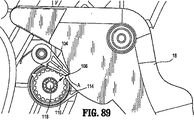
次に図87〜89を参照すると、第1の回転可能部材102が、ロックアウト・ホイール112の歯116に対してラチェット動作を続ける。ロックアウト・ホイール112は、クリップ300のそれぞれが打ち出されるたびに前進し、半径方向に進む。図88に示されているように、第1の回転可能部材102は、爪106がロックアウト・ホイール112の逃げノッチ110に達するまで回転する。次いで、図88に矢印Kによって示されているとおり、逃げノッチ110によって、爪106がロックアウト・ホイール112を横切って出ることができる。
Referring now to FIGS. 87-89, the first
図89を参照すると、その後に爪106は、トリガハンドル18に示されている対応する切り欠き(A)と対をなす。爪106がノッチAと対をなすことで、クリップ取付器10がロックされ、爪106が打ち出し、すなわちトリガ18による駆動部材36の駆動を防止する。その後、クリップ取付器10を適切な受け具に配置することができる。最も好ましくは、クリップ取付器10に、ロックアウト・ホイール112の歯の数を超える数のクリップ300が装填される。この結果、クリップ取付器10がクリップなしの状態で空打ちされることはあり得ない。
Referring to FIG. 89, the
次に図90〜92を参照すると、本発明のクリップ取付器10のいくつかの構成部品について、他の実施形態が示されている。図90を参照すると、ウェッジプレート750、リンクカム752、フィラー部品754、およびスピンドル756の分解図が示されている。
90-92, other embodiments are shown for some components of the clip applier 10 of the present invention. Referring to FIG. 90, an exploded view of the
ウェッジプレート750は、上述した実施形態に類似しており、丸みを帯びた遠位端758を有し、フィラー部品754へと近位端において適切に付勢されている。丸みを帯びた遠位端758は、好ましくは上述のように遠位方向に移動し、クリップ装填のためクリップ取付器10のジョー16の間に配置される。ウェッジプレート750は、リンクカムノッチ760をさらに有している。リンクカムノッチ760は、ウェッジプレート750の実質的に中央部にある。リンクカムノッチ760は、おおむね直交形状であり、ウェッジプレート750の側面に形作られている。リンクカムノッチ760は、ウェッジプレート750のほぼ中央まで延びるための適切な奥行きを有している。あるいは、リンクカムノッチ760が、他の形状を有してもよく、円形または湾曲していてもよい。種々の構成が可能であり、本明細書の開示の範囲に包含される。リンクカムノッチ760は、好ましくは、リンクカム752の係合を可能にし、ウェッジプレート750を遠位方向に移動させることができるようにする。遠位方向の移動によって、丸みを帯びた遠位端758がジョー16の間に導入される。スピンドル756の遠位方向への移動により、所定の境界線においてウェッジプレート750の係合が解除される。
The
図90においてウェッジプレート750の上方に示されているフィラー部品754は、他の構成部品に対して動くことがなく、静止したままであるように意図されている。フィラー部品754は、リンクカム開口762を有している。リンクカム開口762は、リンクカム752のアクセスを可能にすべくフィラー部品754に配置された円形の造作である。リンクカム開口762は、ウェッジプレート750のリンクカムノッチ760に対して相補的な位置にある。この位置により、リンクカム752の一部分を、リンクカムノッチ760に係合させることができる。
The
リンクカム752は、好ましくは2つの別個の部位を有している、リンクカム752は、第1の基部764および第2のアーム766を有している。第1の基部764は、フィラー部品754のリンクカム開口762に位置し、リンクカム開口762に回転可能に取り付けられる。第2のアーム766は、第1の基部764に接続されている。第2のアーム766は、ウェッジプレート750のリンクカムノッチ760に係合可能である。第2のアーム766は、スピンドル756のカム溝768を移動する柱767をさらに有している。リンクカム752は、好ましくは、他の部材を或る固定の距離だけ動かすべく回転する部位を有しており、そのような動きの結果として、その部材を初期の位置へと復帰させる。
The
ここでスピンドル756を参照すると、スピンドル756が、図90においてフィラー部品754およびウェッジプレート750の両者の下方に配置されて示されており、カム溝768を有している。理解できるとおり、ここで遠位側の出発位置770からカム溝768に沿って近位側の終端位置772までカム溝768を参照すると、スピンドル756がストロークにおいて遠位方向へと前進するとき、リンクカム752の第2のアーム766の柱767がカム溝768を移動し、カム溝768の正確な経路に追従することが理解される。柱767が、或る境界線に達するまでカム溝768においてウェッジプレート750を駆動し、次いでばね(図示されていない)またはリンクカム752の他の付勢装置が、柱767を引っ込める。
Referring now to spindle 756,
ここで図91aを参照すると、組み立てられた状態でウェッジプレート750上に位置するフィラー部品754が示されている。この図から理解できるとおり、リンクカム開口762が、フィラー部品754のリンクカム開口762に第1の基部764を位置させた状態で示されている。第1の基部764が、フィラー部品754のリンクカム開口762内で自由に移動および自由に回転できることを、当業者であれば理解すべきである。さらに、リンクカム752の第1の基部764が、フィラー部品754の真下の第2のアーム部(図示されていない)を任意の所望の回転角度範囲で正確に回転させることができ、クリップ取付器10がとくに特定の大きさの回転に限定されないことを、当業者であれば、理解すべきである。
Referring now to FIG. 91a, a
次に図91bを参照すると、スピンドル756上に位置するウェッジプレート750の図が、単に説明のみを目的として図91aのフィラー部品754を取り除いて示されている。今や図91aのフィラー部品754を取り除いた状態で見ることができるように、リンクカム752が、柱(図示されていない)がウェッジプレート750のリンクカムノッチ760に係合させた状態で、第2のアーム766を有している。このやり方で、リンクカム752の第2のアーム766が回転するとき、柱767がウェッジプレート750を遠位方向に押し、遠位側に示されている丸みを帯びた遠位端758をクリップを装填するためにジョー16の間へと駆動することが明らかである。
Referring now to FIG. 91b, a view of the
次に図91cを参照すると、ウェッジプレート750の真下の破線でスピンドル756のカム溝768が示されている。カム溝768の最も遠位側の出発位置772において、カム溝768はリンクカム752の方向を妨げない。しかしながら、第2のアーム766の柱767が破線で示されているカム溝768のカム造作774に接すると、第2のアーム766がカム作用によって反時計方向に動かされ、リンクカムノッチ760に係合してリンクカムノッチ760を遠位方向に押すことで、ウェッジプレート750を駆動する。ストロークにおいてスピンドル756が遠位方向へと駆動され続け、リンクカム752の第2のアーム766の柱767が、カム造作774を過ぎて移動する。当然ながら、この位置において、ウェッジプレートの丸みを帯びた遠位端758が、装填のためにジョー16の間に位置する。
Referring now to FIG. 91c, the
次に図92を参照すると、図91cの窓92に従い、スピンドル756のカム溝768内のリンクカム754の拡大図が示されている。リンクカム754がスピンドル756のカム造作774を過ぎて遠位方向に駆動されるとき、リンクカム754は、カム溝768の最も近位側の位置770へと駆動される。このカム溝768の最も近位側の位置770は、ひとたびジョー16が装填されて、スピンドル756が打ち出しのためのストロークにおいて前進を続けるときに、ウェッジプレート750の引き込みを可能にする。
Referring now to FIG. 92, there is shown an enlarged view of the
次に図93を参照すると、本発明のクリップ取付器10について、他の代案となる実施形態が示されている。この実施形態のクリップ取付器10は、信号装置54を有している。信号装置54は、すでに述べたように、外科の事象が発生したこと、発生しつつあること、または将来発生することを、医師へと通知する。
Referring now to FIG. 93, there is shown another alternative embodiment of the clip applier 10 of the present invention. The clip applier 10 of this embodiment has a
外科の事象とは、クリップ取付器10に関する任意の事象、外科手術に関する任意の事象、または両者であってよい。一実施形態においては、外科の事象は、クリップ取付器10に残っている利用可能な外科用クリップの数に関係するものであり得る。他の実施形態においては、外科の事象は、クリップ300の打ち出しが推奨される時期に関する通知に関係するものであり得る。別の実施形態においては、外科の事象は、クリップ取付器の空打ちまたは空打ち防止に関係するものであり得、信号装置54が、クリップ取付器10内の外科用クリップ300の数が少なすぎ、新たなクリップ取付器10または他の装置を入手すべきである旨を、医師へと警報することができる。他の実施形態においては、外科の事象は、手術の総時間など、外科の他の重要または便利なパラメータであってよい。種々の構成が可能であって、本明細書の開示の範囲に包含され、信号装置54は、好ましくは、とくには他の内視鏡器具の使用との組み合わせにおいて、容易に見ることができないパラメータをフィードバックして医師を助ける。
A surgical event may be any event related to clip applier 10, any event related to surgery, or both. In one embodiment, the surgical event may be related to the number of available surgical clips remaining in the clip applier 10. In other embodiments, the surgical event may be related to a notification regarding when the launch of the
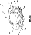
次に図93を参照すると、信号装置54の第1の構成部品776が示されている。第1の構成部品776は、円筒形の部材である。第1の構成部品776は、好ましくは、近位開口778を有している。近位開口778は、チャネル780を有している。さらにチャネル780が、第1の構成部品776の横側へと広がる第1および第2の横サブチャネル780aおよび780bを有している。さらに、近位開口778は、チャネル780の内側を囲むように配置された内部横表面780cを有している。
Referring now to FIG. 93, the
さらに第1の構成部品776は、カム造作784を有する遠位側782を有している。この実施形態においては、遠位側782が、第1および第2の尖った端部786、788であるカム造作784を有している。ここで図94を参照すると、第1の構成部品776の上面図が示されている。これらの図から理解できるように、第1および第2の尖った端部786および788(第1の端部は、図93に示した図の側面図によって遮られている)が、遠位側782において第1の構成部品776から離れるように外向きに突き出している。第1の構成部品776は、さらに棚状部787を有している。ここで図95を参照すると、第1の構成部品776の上面図が示されている。第1の構成部品776(この図において)は、遠位側782から外向きに延びる第1および第2の尖った端部786、788を有している。
Further, the
次に図96を参照すると、近位開口778およびチャネル780の図が示されている。理解できるとおり、チャネル780は、内側に他の部材がアクセスできるように適切に寸法作られている。さらにチャネル780は、第1の横サブチャネル780aおよび第2の横サブチャネル780bを備える側面を有している。
Referring now to FIG. 96, a view of
次に図97を参照すると、信号装置54の第2の構成部品790が示されている。第2の構成部品790は、レバー式の構造であり、説明の目的のために参照符号Aで示されている1つの回転軸を中心として、回転可能である。第2の構成部品790は、主柱792を有している。主柱792は、カム面796を有する基部794上に位置しており、第1の構成部品776へと挿入される。好ましくは、カム面796が、第1および第2の尖った端部786および788の一方を受け入れるために適した寸法を有している。当然ながら、第2の構成部品790は回転する。
Referring now to FIG. 97, the
第2の構成部品790は、さらに別の第2の柱902および第3の柱904を有している。第2の柱902は、リンク906によって主柱792へと接続され、第3の柱904は、別の第2のリンク908によって主柱792へと接続されている。好ましくは、主柱792が、第1の構成部品776のチャネル780へと延び、第1の尖った端部786が、カム面796の第1のサブ凹所910に係合する。回転の際、第1の構成部品776の第1の尖った端部786が、カム面796に乗り、第1の構成部品776を第2の構成部品790から離れるように動かす。第1の構成部品776が回転させられて、長手方向軸Aと平行な方向に第2の構成部品790から離れるように動かされるとき、第1の尖った端部786が、第1のサブ凹所910から隣の第2のサブ凹所912へと好都合に移動する。
The
ここで、図98に示したクリップ取付器10のハンドル部12の内面図を参照すると、内向きにハンドル部12へと延びるリブ部914が示されている。リブ部914は、円柱形の造作である。リブ部914は、好ましくは、ハンドル部12へと成型される。リブ部914は、横ストリップ916を有している。横ストリップ916は、円柱形のリブ部914に一体に接続された直交形状の部材である。
Referring now to the inner view of the
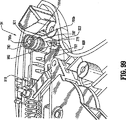
図99が、クリップ取付器10のハンドル部12の反対側の横側の内面図を示しており、図98に示したハンドル部12の部位に組み合わせられる。図98は、クリップ取付器10の信号装置54について、途中まで組み立てられた図を示しており、第1の構成部品776の棚状部787に位置するばね901を有している。図98から理解できるように、リブ部916の横ストリップ916(図98に示されている)が、第1の円筒部776を通って配置され、第1の円筒部776に係合している。横ストリップ916は、第1の構成部品776の回転を防止している。第1の構成部品776が、固定されているリブ部914の横ストリップ916(図98に示されている)に対して回転しようとすると、横ストリップ916が第1の構成部品776に接し、第1の横サブチャネル780aの側面との接触によって第1の構成部品776の移動を防止する。
99 shows an inner side view of the side opposite to the
さらに図98を参照すると、駆動バー918がアクチュエータ板920へと接続されている。この実施形態において、アクチュエータ板920は、近位側に切り欠き922を有している。切り欠き922が、第2の構成部品790の第2の柱902に係合する。駆動バー918が遠位方向に駆動されるとき、さらに駆動バー918が、同様の様相でアクチュエータ板920を遠位方向に押す。さらに、切り欠き922を有しているアクチュエータ板920が、第2の構成部品790の第2の柱902(図97に示されている)を回転させる。第2の構成部品790が、同様に反時計の様相で回転し、カムノッチ796(図97に示されている)を回転させる。カムノッチ796(図97に示されている)も回転し、第1の構成部品776の第1の尖った端部786(図95に示されている)を回転させようとする。しかしながら、横ストリップ916(図98に示されている)が、そのような回転を防止している。これにより、ばね901が第1の構成部品776を第2の構成部品790に向かって内向きに付勢している状態で、第1の構成部品776が第2の構成部品790から離れるように移動する。次いで、カムノッチ796が、第1の構成部品776を第2の構成部品790から引き離し、カムノッチ796に乗せる。第1の構成部品776がカムノッチ796へと移動するとき、第1の構成部品776が、ばね901の付勢によって復帰して、第2の構成部品790に鋭く衝突する。この第1の構成部品776と第2の構成部品790との間の鋭い衝突が、クリップの打ち出しなどといった外科の事象について聞き取り可能なクリック音を生じさせる。この知らせが、クリップが打ち出された旨のフィードバックを医師へともたらす。種々の構成が可能であり、本明細書の開示の範囲に包含される。
Still referring to FIG. 98, the drive bar 918 is connected to the
以上の説明が、あくまで本明細書の開示の例示にすぎないことを、理解すべきである。当業者であれば、本明細書の開示から離れることなく、種々の代案および変更を考え出すことができる。したがって、本明細書の開示は、そのような代案、変更、および変種のすべてを包含するものである。添付の図面を参照しつつ説明した実施形態は、あくまで本明細書の特定の実施例を実証するために提示されているにすぎない。上述の構成要素、工程、方法、および技法、ならびに/あるいは添付の特許請求の範囲の構成要素、工程、方法、および技法から実質的に相違していない他の構成要素、工程、方法、および技法も、本明細書の開示の範囲に包含されるべきものである。 It should be understood that the above description is merely illustrative of the disclosure herein. Various alternatives and modifications can be devised by those skilled in the art without departing from the disclosure herein. Accordingly, the disclosure herein includes all such alternatives, modifications, and variations. The embodiments described with reference to the accompanying drawings are presented merely to demonstrate certain examples herein. Other components, steps, methods and techniques described above, and / or other components, steps, methods and techniques that do not substantially differ from the components, steps, methods and techniques of the appended claims. Are intended to be included within the scope of the disclosure herein.
Claims (39)
・ハンドル部(12)、
・ハンドル部から遠位方向に延び、長手方向軸を定めている細長い筒状部材(14)、
・前記細長い筒状部材内に配置された複数の外科用クリップ(300)、
・前記細長い筒状部材を通る長手方向移動のために取り付けられるスピンドル(128)、
・離間位置と近接位置との間で可動である第1および第2のジョー部分をさらに有しており、前記細長い筒状部材の遠位端部に隣接して取り付けられているジョーアセンブリ(16)、
・「C」形状窓(610)を有し、そして前記第1および前記第2のジョー部分の間を長手方向に可動であるウェッジプレート(600)、
・前記ジョー部分が離間位置にあるときに、前記ジョーアセンブリへと外科用クリップを1つずつ遠位方向に前進させるように構成された供給バー(400)、
・前記ハンドル部内に長手方向に配置され、前記ハンドル部の操作に応答して長手方向に可動であるアクチュエータ板(50)、
・前記第1および前記第2のジョー部分を近接位置へと動かすため、前記ジョー部分に隣接して配置された駆動バー(200)、および
・前記ウェッジプレート内の前記「C」形状窓と係合するように構成された回転可能部材(702)を有しており、
前記スピンドルが、前記ウェッジプレートを、最も遠位側の位置へと所定の距離だけ長手方向に前進させ、
前記ウェッジプレートが、前記最も遠位側の位置において前記第1および前記第2のジョー部分の間に配置される丸みのある遠位端(616)を有しており、前記ウェッジプレートの丸みのある遠位端が、前記外科用クリップの装填の際に前記ジョーアセンブリを前記離間位置に保つように構成され、前記ウェッジプレートの丸みのある遠位端が、前記装填の際に前記ジョーアセンブリに加わるトルクおよび外力を軽減し、
前記回転可能部材が、前記ジョーアセンブリへの前記外科用クリップの前記装填の際に、前記ウェッジプレートを前記最も遠位側の位置に保持し、
前記回転可能部材が、前記装填の終了時に前記スピンドルのカム造作(210)によって第1の位置から第2の位置に偏向させられ、前記カム造作が、前記回転可能部材を前記ウェッジプレートとの係合から解放するよう構成され、そして前記ウェッジプレートの前記最も遠位側の位置からの引き込みを可能にする、装置。A device for applying a surgical clip to body tissue,
-Handle part (12),
An elongated tubular member (14) extending distally from the handle portion and defining a longitudinal axis;
A plurality of surgical clips (300) disposed within the elongated tubular member;
A spindle (128) mounted for longitudinal movement through the elongated tubular member;
A jaw assembly (16) further comprising first and second jaw portions movable between a spaced position and a proximal position, wherein the jaw assembly is mounted adjacent the distal end of the elongated tubular member; ),
A wedge plate (600) having a “C” shaped window (610) and movable longitudinally between the first and second jaw portions;
A supply bar (400) configured to advance surgical clips one by one distally into the jaw assembly when the jaw portion is in the spaced position;
An actuator plate (50) disposed longitudinally within the handle portion and movable in the longitudinal direction in response to operation of the handle portion;
A drive bar (200) disposed adjacent to the jaw portion for moving the first and second jaw portions to a proximal position; and engaging the "C" shaped window in the wedge plate A rotatable member (702) configured to mate,
The spindle advances the wedge plate longitudinally a predetermined distance to the most distal position;
The wedge plate has a rounded distal end (616) disposed between the first and second jaw portions at the most distal position, the rounded edge of the wedge plate A distal end is configured to keep the jaw assembly in the spaced position during loading of the surgical clip, and a rounded distal end of the wedge plate is coupled to the jaw assembly during loading. Reduce applied torque and external force,
The rotatable member holds the wedge plate in the most distal position during the loading of the surgical clip into the jaw assembly;
The rotatable member is deflected from a first position to a second position by the cam feature (210) of the spindle at the end of the loading, and the cam feature causes the rotatable member to engage the wedge plate. An apparatus configured to release from the joint and allowing retraction of the wedge plate from the most distal position.
前記ウェッジプレートが、カム溝(612)を有しており、
前記カムリンク(208)が、前記カム溝(612)内のカム面(614)に係合可能であり、
前記カムリンク(208)が前記カム面(614)に接触することで、前記ウェッジプレートが前記ジョーアセンブリの前記第1のジョー部分と前記第2のジョー部分との間を遠位方向に動かされる、請求項1に記載の装置。The spindle (128) has a cam link (208);
The wedge plate has a cam groove (612);
The cam link (208) is engageable with a cam surface (614) in the cam groove (612);
The cam link (208) contacts the cam surface (614) so that the wedge plate is moved distally between the first jaw portion and the second jaw portion of the jaw assembly. The apparatus of claim 1.
前記フィラー部品が、切り離しのカム面(726)を有する、構成部品であるカム溝(720)を有しており、
前記構成部品であるカム溝(720)が、前記ウェッジプレートの前記カム溝(612)に整列しており、
前記ウェッジプレートが前記最も遠位側の位置にあるとき、前記カムリンクのカムリンクボス(231)が、前記切り離しのカム面(726)に接し、そして前記フィラー部品の前記切り離しのカム面(726)が、前記カムリンクボス(231)を前記ウェッジプレートの前記カム面(614)との係合から外すように横方向に駆動し、前記フィラー部品が前記ウェッジプレートの遠位方向への動きを終結させる、請求項2に記載の装置。A filler part (700) disposed under the wedge plate;
The filler part has a cam groove (720), which is a component part, having a separate cam surface (726);
The cam groove (720) which is the component is aligned with the cam groove (612) of the wedge plate,
When the wedge plate is in the most distal position, the cam link boss (231) of the cam link contacts the detaching cam surface (726) and the detaching cam surface (726) of the filler part. ) Laterally drive the cam link boss (231) out of engagement with the cam surface (614) of the wedge plate, and the filler component causes the wedge plate to move distally. The apparatus of claim 2, wherein the apparatus is terminated.
前記トリガーまたは前記ハンドル部の少なくとも一方の対応するラック(40)の歯(44)と対をなす爪(46)を有しているロックアウト機構(56)をさらに有しており、
前記ロックアウト機構が作動しているとき、前記爪が、前記トリガーまたは前記ハンドル部の前記少なくとも一方によって前記アクチュエータ板が長手方向に動かされることがないように阻止している、請求項1に記載の装置。A trigger (18) movably attached to the handle portion (12);
Has said trigger, or at least one of the handle portions corresponding rack (40) of the teeth (44) and the lockout mechanism has a pawl (46) of the pair (56) further,
When the lockout mechanism is in operation, it said pawl, said actuator plate by said at least one of the trigger or the handle portion is blocked so as not to be moved longitudinally, in claim 1 The device described.
前記装置が、前記複数の歯の数と少なくとも同じ数の外科用クリップを有しており、
前記複数の外科用クリップが使い果たされたときに、前記第1の回転可能部材の爪が前記切り欠きへと前進し、前記第1の回転可能部材がさらに回転し、そして前記爪が前記切り欠きを横切って前記第2の回転可能部材から出て、前記第1の回転可能部材の爪が前記ハンドル部の前記対応する切り欠きと対をなすように構成されている、装置。10. The device of claim 9, wherein the pawl of the first rotatable member rotates on the inner surface of the second rotatable member so as to mesh with the plurality of teeth.
The device has at least as many surgical clips as the number of teeth;
When the plurality of surgical clips are used up, the pawl of the first rotatable member advances into the notch, the first rotatable member further rotates, and the pawl is An apparatus configured to exit the second rotatable member across a notch and the pawl of the first rotatable member is paired with the corresponding notch of the handle portion.
前記ハンドル部がリブ(2)を有しており、
ハンドル部の操作に応答して前記アクチュエータ板が長手方向に移動するとき、前記アクチュエータ板が前記信号装置(54)を回転させ、前記クリックレバー(78)を回転させて前記リブに接触させ、前記接触が前記外科用クリップが打ち出された旨を聴覚によって知らせる、請求項1に記載の装置。A signal device (54) having a click lever (78) and a biasing portion (80);
The handle portion has a rib (2);
When the actuator plate in response to operation of the handle portion moves longitudinally, the actuator plate rotates the signal device (54), is rotated in contact with the rib the click lever (78), The apparatus according to claim 1, wherein the contact audibly signals that the surgical clip has been fired.
・ハンドル(12)、
・前記ハンドルから遠位方向に延び、長手方向軸を定めている細長い筒状部材(14)、
・前記細長い筒状部材内に配置された複数の外科用クリップ(300)、
・前記細長い筒状部材を通る長手方向移動のために取り付けられるスピンドル(128)、
・離間位置と近接位置との間で可動である第1および第2のジョー部分をさらに有しており、前記細長い筒状部材の遠位端部に隣接して取り付けられているジョーアセンブリ(16)、
・前記第1および前記第2のジョー部分の間を長手方向に可動であるウェッジプレート(600)、
・前記ジョー部分が前記離間位置にあるときに、前記ジョーアセンブリへと外科用クリップを1つずつ遠位方向に前進させるように構成された供給バー(400)、
・前記ハンドル内に長手方向に配置され、前記ハンドルの操作に応答して長手方向に可動であるアクチュエータ板(50)、および
・前記第1および前記第2のジョー部分を前記近接位置へと動かすため、前記ジョー部分に隣接して配置された駆動バー(200)を有しており、
前記スピンドルが、前記ウェッジプレートを、最も遠位側の位置へと所定の距離だけ長手方向に前進させ、
前記ウェッジプレートが、前記最も遠位側の位置において前記第1および前記第2のジョー部分の間に配置される丸みのある遠位端(616)を有しており、前記ウェッジプレートの丸みのある遠位端が、前記外科用クリップの装填の際に前記ジョーアセンブリを前記離間位置に保つように構成され、前記ウェッジプレートの丸みのある遠位端が、前記装填の際に前記ジョーアセンブリに加わるトルクおよび外力を軽減し、
前記アクチュエータ板が、さらに信号装置(22)を動作させ、前記信号装置が、前記複数の外科用クリップの少なくとも1つが打ち出された旨の知らせをもたらす、装置。A device for applying a surgical clip to body tissue,
-Handle (12),
- said hand extends in Le whether et distally, the elongated tubular member which defines a longitudinal axis (14),
A plurality of surgical clips (300) disposed within the elongated tubular member;
A spindle (128) mounted for longitudinal movement through the elongated tubular member;
A jaw assembly (16) further comprising first and second jaw portions movable between a spaced position and a proximal position, wherein the jaw assembly is mounted adjacent the distal end of the elongated tubular member; ),
A wedge plate (600) movable longitudinally between the first and second jaw portions;
A supply bar (400) configured to advance a surgical clip distally one by one into the jaw assembly when the jaw portion is in the spaced position;
- arranged in a longitudinal direction to the hand in Le, the actuator plate is longitudinally movable in response to operation of the handle (50), and - the first and the second jaw portions to the approximated position And has a drive bar (200) disposed adjacent to the jaw portion,
The spindle advances the wedge plate longitudinally a predetermined distance to the most distal position;
The wedge plate has a rounded distal end (616) disposed between the first and second jaw portions at the most distal position, the rounded edge of the wedge plate A distal end is configured to keep the jaw assembly in the spaced position during loading of the surgical clip, and a rounded distal end of the wedge plate is coupled to the jaw assembly during loading. Reduce applied torque and external force,
The apparatus, wherein the actuator plate further operates a signaling device (22), wherein the signaling device provides notification that at least one of the plurality of surgical clips has been fired.
前記電気レバーが、前記電気レバーの切り替わりにもとづいて表示されるパラメータを現在のパラメータへと変化させ、自由端(190)と固定端(77)とを有する可動部材(54)をさらに備え、前記固定端が前記ハンドルおよび前記アクチュエータ板へと接続されており、
前記アクチュエータ板が前記ハンドルの操作に応答して長手方向に移動するとき、前記アクチュエータ板が前記可動部材を運動させ、前記可動部材が前記自由端を前記電気レバーに接するように運動させ、前記レバーが前記画像表示装置を前記表示されたパラメータから前記現在のパラメータへと変化させる、請求項13に記載の装置。An electric lever (52),
The electric lever further comprises a movable member (54) having a free end (190) and a fixed end (77) that changes a parameter displayed based on switching of the electric lever to a current parameter, fixed end is connected to said handle contact and the actuator plate,
When said actuator plate is moved in the longitudinal direction in response to an operation of said handle, said actuator plate so that exercising the movable member, the movable member is exercised so as to contact said free end to said electric lever, the 14. The device of claim 13, wherein a lever changes the image display device from the displayed parameter to the current parameter.
・ハンドル部(12)、
・前記ハンドル部から遠位方向に延び、長手方向軸を定めている細長い筒状部材(14)、
・前記細長い筒状部材(14)内に配置された複数の外科用クリップ(300)、
・前記細長い筒状部材を通る長手方向移動のために取り付けられるスピンドル(128)、
・離間位置と近接位置との間で可動である第1および第2のジョー部分をさらに有しており、前記細長い筒状部材の遠位端部に隣接して取り付けられているジョーアセンブリ(16)、
・前記第1および前記第2のジョー部分の間を長手方向に可動であるウェッジプレート(600)、
・前記ジョー部分が前記離間位置にあるときに、前記ジョーアセンブリへと外科用クリップを1つずつ遠位方向に前進させるように構成された供給バー(400)、
・前記ハンドル部内に長手方向に配置され、前記ハンドル部の操作に応答して長手方向に可動であるアクチュエータ板(50)、および
・前記第1および前記第2のジョー部分を前記近接位置へと動かすため、前記ジョー部分に隣接して配置された駆動バー(200)を有しており、前記スピンドルが、前記ウェッジプレートを、最も遠位側の位置へと所定の距離だけ長手方向に前進させ、
前記ウェッジプレートが、前記最も遠位側の位置において前記第1および前記第2のジョー部分の間に配置される丸みのある遠位端(616)を有しており、前記ウェッジプレートの丸みのある遠位端が、前記外科用クリップの装填の際に前記ジョーアセンブリを前記離間位置に保つように構成され、前記ウェッジプレートの丸みのある遠位端が、前記装填の際に前記ジョーアセンブリに加わるトルクを軽減し、前記アクチュエータ板が、前記複数の外科用クリップの少なくとも1つが打ち出された旨を知らせるように構成された可聴装置(54)をさらに動作させる、装置。A device for applying a surgical clip to body tissue,
-Handle part (12),
An elongated tubular member (14) extending distally from the handle portion and defining a longitudinal axis;
A plurality of surgical clips (300) disposed within the elongated tubular member (14);
A spindle (128) mounted for longitudinal movement through the elongated tubular member;
A jaw assembly (16) further comprising first and second jaw portions movable between a spaced position and a proximal position, wherein the jaw assembly is mounted adjacent the distal end of the elongated tubular member; ),
A wedge plate (600) movable longitudinally between the first and second jaw portions;
A supply bar (400) configured to advance a surgical clip distally one by one into the jaw assembly when the jaw portion is in the spaced position;
An actuator plate (50) disposed longitudinally within the handle portion and movable in the longitudinal direction in response to operation of the handle portion; and the first and second jaw portions to the proximate position For movement, it has a drive bar (200) positioned adjacent to the jaw portion, and the spindle advances the wedge plate longitudinally a predetermined distance to the most distal position. ,
The wedge plate has a rounded distal end (616) disposed between the first and second jaw portions at the most distal position, the rounded edge of the wedge plate A distal end is configured to keep the jaw assembly in the spaced position during loading of the surgical clip, and a rounded distal end of the wedge plate is coupled to the jaw assembly during loading. An apparatus for reducing applied torque and further operating an audible device (54) configured to inform the actuator plate that at least one of the plurality of surgical clips has been fired.
前記クリックレバーが、前記アクチュエータ板へと接続され、
前記可聴装置が、前記ハンドル部の内側ハウジング内でリブ(2)に連結され、
前記アクチュエータ板が遠位方向に移動するとき、前記アクチュエータ板が前記クリックレバーを回転させ、前記クリックレバーが回転して前記リブに接触し、前記接触によって音波が生じ、前記音波が前記複数の外科用クリップの少なくとも1つが打ち出された旨を知らせるように構成されている、請求項16に記載の装置。The audible device has a click lever (78);
The click lever is connected to the actuator plate;
The audible device is connected to a rib (2) within the inner housing of the handle part;
When the actuator plate moves in the distal direction, the actuator plate rotates the click lever, the click lever rotates to contact the rib, and the contact generates a sound wave, and the sound wave is generated in the plurality of surgical instruments. The apparatus of claim 16, wherein the apparatus is configured to indicate that at least one of the working clips has been fired.
前記アクチュエータ板が遠位方向に移動するとき、前記アクチュエータ板がレバー(52)を動かし、前記レバーが前記電気カウンタ・コンタクト板に接触し、前記接触によって、前記表示装置が前記パラメータから現在の表示パラメータへと変化する、請求項18に記載の装置。The image display device comprises a display device having an electrical counter contact plate (100), the display device displaying parameters relating to the application of the surgical clip;
When the actuator plate moves in the distal direction, the actuator plate moves the lever (52), the lever contacts the electrical counter contact plate, and the contact causes the display device to display the current indication from the parameter. The apparatus of claim 18, wherein the apparatus changes to a parameter.
前記装置が、さらに前記ウェッジプレートのカム溝と整列されているフィラー部品のカム溝(720)を有し、そして前記フィラー部品の切り離しのカム面(726)、近位側の窓(706)および前記近位側の窓内のばね棒部材(704)を有しており、前記フィラー部品は、前記細長い筒状部材に固定されており、
さらに前記装置が、前記フィラー部品の近位側の窓へと接続された回転可能部材(702)を有しており、前記回転可能部材が第1の端部(708)および第2の端部(710)を有していて、前記第1の端部が前記ばね棒部材によって付勢されており、
前記スピンドルが、カムリンク(208)を有し、前記カムリンクが、前記ウェッジプレートのカム溝内を遠位方向に駆動され、前記カムリンク(208)が前記ウェッジプレートカム面に接触して前記ウェッジプレートを遠位方向に動かし、前記丸みを帯びた遠位端が装填のために前記ジョーアセンブリの間へと動かされる、装置。17. The apparatus of claim 16, wherein the wedge plate further comprises a cam groove (612), the cam groove comprising a wedge plate cam surface (614), wherein the wedge plate is a proximal window (622). And the apparatus further includes a filler part cam groove (720) aligned with the wedge plate cam groove, and the filler part release cam surface (726), A proximal window (706) and a spring bar member (704) in the proximal window, the filler component being secured to the elongated tubular member;
The device further includes a rotatable member (702) connected to a window proximal to the filler component, the rotatable member having a first end (708) and a second end. (710), wherein the first end is biased by the spring bar member;
The spindle has a cam link (208), the cam link is driven distally within a cam groove of the wedge plate, and the cam link (208) contacts the wedge plate cam surface to An apparatus wherein a wedge plate is moved distally and the rounded distal end is moved between the jaw assemblies for loading.
・ハンドル部(12)、
・前記ハンドル部から遠位方向に延び、長手方向軸を定めている細長い筒状部材(14)、
・前記細長い筒状部材内に配置された複数の外科用クリップ(300)、
・前記細長い筒状部材を通る長手方向移動のために取り付けられるスピンドル(128)、
・離間位置と近接位置との間で可動である第1および第2のジョー部分をさらに有しており、前記細長い筒状部材の遠位端部に隣接して取り付けられているジョーアセンブリ(16)、
・前記第1および前記第2のジョー部分の間を長手方向に可動であるウェッジプレート(600)、
・前記ジョー部分が前記離間位置にあるときに、前記ジョーアセンブリへと外科用クリップを1つずつ遠位方向に前進させるように構成された供給バー(400)、
・前記ハンドル部内に長手方向に配置され、前記ハンドル部の操作に応答して長手方向に可動であるアクチュエータ板(50)、および
・前記第1および前記第2のジョー部分を前記近接位置へと動かすため、前記ジョー部分に隣接して配置された駆動バー(200)を有しており、
前記スピンドルが、前記ウェッジプレートを、最も遠位側の位置へと所定の距離だけ長手方向に前進させ、
前記ウェッジプレートが、前記最も遠位側の位置において前記第1および前記第2のジョー部分の間に配置される丸みのある遠位端(616)を有しており、前記ウェッジプレートの丸みのある遠位端が、前記外科用クリップの装填の際に前記ジョーアセンブリを前記離間位置に保つように構成され、前記ウェッジプレートの丸みのある遠位端が、前記装填の際に前記ジョーアセンブリに加わるトルクを軽減し、前記細長い筒状の部材が、回転可能部材(20)によって前記ハンドル部へと接続され、前記回転可能部材が、前記ハンドル部および前記細長い筒状の部材に固定して接続され、前記回転可能部材の回転時に、前記細長い筒状の部材が回転するとともに前記ジョー部分が回転し、
前記回転可能部材が、第1の細長いノブハウジング(136)と周囲に複数の切り欠きが配置されてなる第2のノブ(20)とを有する複数の部材であり、前記第2のノブが、前記ノブハウジングを覆って配置されており、
前記複数の部材の少なくとも一つが、前記細長い筒状の部材を回転させるべく人差し指によって回転させられるように構成されている、装置。A device for applying a surgical clip to body tissue,
-Handle part (12),
An elongated tubular member (14) extending distally from the handle portion and defining a longitudinal axis;
A plurality of surgical clips (300) disposed within the elongated tubular member;
A spindle (128) mounted for longitudinal movement through the elongated tubular member;
A jaw assembly (16) further comprising first and second jaw portions movable between a spaced position and a proximal position, wherein the jaw assembly is mounted adjacent the distal end of the elongated tubular member; ),
A wedge plate (600) movable longitudinally between the first and second jaw portions;
A supply bar (400) configured to advance a surgical clip distally one by one into the jaw assembly when the jaw portion is in the spaced position;
An actuator plate (50) disposed longitudinally within the handle portion and movable in the longitudinal direction in response to operation of the handle portion; and the first and second jaw portions to the proximate position A drive bar (200) disposed adjacent to the jaw portion for movement;
The spindle advances the wedge plate longitudinally a predetermined distance to the most distal position;
The wedge plate has a rounded distal end (616) disposed between the first and second jaw portions at the most distal position, the rounded edge of the wedge plate A distal end is configured to keep the jaw assembly in the spaced position during loading of the surgical clip, and a rounded distal end of the wedge plate is coupled to the jaw assembly during loading. The applied torque is reduced, and the elongated cylindrical member is connected to the handle portion by a rotatable member (20), and the rotatable member is fixedly connected to the handle portion and the elongated cylindrical member. When the rotatable member rotates, the elongated cylindrical member rotates and the jaw portion rotates,
The rotatable member is a plurality of members having a first elongated knob housing (136) and a second knob (20) having a plurality of cutouts disposed around the first elongated knob housing (136), and the second knob comprises: Disposed over the knob housing;
An apparatus wherein at least one of the plurality of members is configured to be rotated by an index finger to rotate the elongated cylindrical member.
前記タブが、電池の電気コンタクトと前記画像表示装置との間に配置されており、
前記タブが、前記電池の枯渇を防止するため前記電池と前記画像表示装置との間に取り外し可能に接続され、最初の使用時に前記タブを取り除くことで前記画像表示装置にエネルギーが供給される、請求項28に記載の装置。The image display device driven by the battery has a tab,
The tab is disposed between a battery electrical contact and the image display device;
The tab is detachably connected between the battery and the image display device to prevent depletion of the battery, and energy is supplied to the image display device by removing the tab at the first use. 30. The apparatus of claim 28.
Applications Claiming Priority (5)
| Application Number | Priority Date | Filing Date | Title |
|---|---|---|---|
| US61701604P | 2004-10-08 | 2004-10-08 | |
| US61710404P | 2004-10-08 | 2004-10-08 | |
| US60/617,016 | 2004-10-08 | ||
| US60/617,104 | 2004-10-08 | ||
| PCT/US2005/036090 WO2006042076A2 (en) | 2004-10-08 | 2005-10-07 | An endoscopic surgical clip applier |
Related Child Applications (2)
| Application Number | Title | Priority Date | Filing Date |
|---|---|---|---|
| JP2011141025A Division JP2011235117A (en) | 2004-10-08 | 2011-06-24 | Endoscopic surgical clip applier |
| JP2011141024A Division JP5242742B2 (en) | 2004-10-08 | 2011-06-24 | Endoscopic surgical clip applier |
Publications (2)
| Publication Number | Publication Date |
|---|---|
| JP2008515550A JP2008515550A (en) | 2008-05-15 |
| JP5103183B2 true JP5103183B2 (en) | 2012-12-19 |
Family
ID=36148936
Family Applications (8)
| Application Number | Title | Priority Date | Filing Date |
|---|---|---|---|
| JP2007535828A Expired - Fee Related JP5103183B2 (en) | 2004-10-08 | 2005-10-07 | Endoscopic surgical clip applier |
| JP2007535830A Expired - Fee Related JP5047799B2 (en) | 2004-10-08 | 2005-10-07 | Endoscopic surgical clip applier |
| JP2007535849A Expired - Fee Related JP4833988B2 (en) | 2004-10-08 | 2005-10-07 | Endoscopic surgical clip applier |
| JP2011128693A Expired - Fee Related JP5341139B2 (en) | 2004-10-08 | 2011-06-08 | Endoscopic surgical clip applier |
| JP2011141025A Withdrawn JP2011235117A (en) | 2004-10-08 | 2011-06-24 | Endoscopic surgical clip applier |
| JP2011141024A Expired - Fee Related JP5242742B2 (en) | 2004-10-08 | 2011-06-24 | Endoscopic surgical clip applier |
| JP2011211580A Withdrawn JP2012030090A (en) | 2004-10-08 | 2011-09-27 | Endoscopic surgical clip applier |
| JP2013035338A Expired - Fee Related JP5492318B2 (en) | 2004-10-08 | 2013-02-26 | Endoscopic surgical clip applier |
Family Applications After (7)
| Application Number | Title | Priority Date | Filing Date |
|---|---|---|---|
| JP2007535830A Expired - Fee Related JP5047799B2 (en) | 2004-10-08 | 2005-10-07 | Endoscopic surgical clip applier |
| JP2007535849A Expired - Fee Related JP4833988B2 (en) | 2004-10-08 | 2005-10-07 | Endoscopic surgical clip applier |
| JP2011128693A Expired - Fee Related JP5341139B2 (en) | 2004-10-08 | 2011-06-08 | Endoscopic surgical clip applier |
| JP2011141025A Withdrawn JP2011235117A (en) | 2004-10-08 | 2011-06-24 | Endoscopic surgical clip applier |
| JP2011141024A Expired - Fee Related JP5242742B2 (en) | 2004-10-08 | 2011-06-24 | Endoscopic surgical clip applier |
| JP2011211580A Withdrawn JP2012030090A (en) | 2004-10-08 | 2011-09-27 | Endoscopic surgical clip applier |
| JP2013035338A Expired - Fee Related JP5492318B2 (en) | 2004-10-08 | 2013-02-26 | Endoscopic surgical clip applier |
Country Status (7)
| Country | Link |
|---|---|
| US (9) | US7717926B2 (en) |
| EP (8) | EP2641549B1 (en) |
| JP (8) | JP5103183B2 (en) |
| AU (3) | AU2005294233B8 (en) |
| CA (4) | CA2582142C (en) |
| ES (3) | ES2717309T3 (en) |
| WO (3) | WO2006042076A2 (en) |
Cited By (1)
| Publication number | Priority date | Publication date | Assignee | Title |
|---|---|---|---|---|
| KR20190069108A (en) * | 2017-12-11 | 2019-06-19 | 랩앤피플주식회사 | Medical applier |
Families Citing this family (611)
| Publication number | Priority date | Publication date | Assignee | Title |
|---|---|---|---|---|
| MXPA04009907A (en) * | 2002-04-10 | 2004-12-07 | Tyco Healthcare | Surgical clip applier with high torque jaws. |
| JP4319980B2 (en) | 2002-06-11 | 2009-08-26 | タイコ ヘルスケア グループ エルピー | Hernia mesh tack |
| EP3170459A1 (en) | 2003-03-11 | 2017-05-24 | Covidien LP | Clip applying apparatus with angled jaw |
| US9060770B2 (en) | 2003-05-20 | 2015-06-23 | Ethicon Endo-Surgery, Inc. | Robotically-driven surgical instrument with E-beam driver |
| US20070084897A1 (en) | 2003-05-20 | 2007-04-19 | Shelton Frederick E Iv | Articulating surgical stapling instrument incorporating a two-piece e-beam firing mechanism |
| US8926637B2 (en) | 2003-06-13 | 2015-01-06 | Covidien Lp | Multiple member interconnect for surgical instrument and absorbable screw fastener |
| EP1635723B1 (en) | 2003-06-13 | 2011-08-10 | Tyco Healthcare Group LP | Multiple member interconnect for surgical instrument and absorbable screw fastener |
| US10478179B2 (en) | 2004-04-27 | 2019-11-19 | Covidien Lp | Absorbable fastener for hernia mesh fixation |
| US8215531B2 (en) | 2004-07-28 | 2012-07-10 | Ethicon Endo-Surgery, Inc. | Surgical stapling instrument having a medical substance dispenser |
| US11896225B2 (en) | 2004-07-28 | 2024-02-13 | Cilag Gmbh International | Staple cartridge comprising a pan |
| GB0420505D0 (en) * | 2004-09-14 | 2004-10-20 | Wild Andrew M | Apparatus for dispensing surgical clips |
| US8409222B2 (en) * | 2004-10-08 | 2013-04-02 | Covidien Lp | Endoscopic surgical clip applier |
| EP2641549B1 (en) | 2004-10-08 | 2015-08-12 | Covidien LP | An endoscopic surgical clip applier |
| US9763668B2 (en) | 2004-10-08 | 2017-09-19 | Covidien Lp | Endoscopic surgical clip applier |
| US7819886B2 (en) * | 2004-10-08 | 2010-10-26 | Tyco Healthcare Group Lp | Endoscopic surgical clip applier |
| JP4783372B2 (en) | 2004-10-08 | 2011-09-28 | タイコ ヘルスケア グループ エルピー | Device for applying a surgical clip |
| US11484312B2 (en) | 2005-08-31 | 2022-11-01 | Cilag Gmbh International | Staple cartridge comprising a staple driver arrangement |
| US7669746B2 (en) | 2005-08-31 | 2010-03-02 | Ethicon Endo-Surgery, Inc. | Staple cartridges for forming staples having differing formed staple heights |
| US11246590B2 (en) | 2005-08-31 | 2022-02-15 | Cilag Gmbh International | Staple cartridge including staple drivers having different unfired heights |
| US7934630B2 (en) | 2005-08-31 | 2011-05-03 | Ethicon Endo-Surgery, Inc. | Staple cartridges for forming staples having differing formed staple heights |
| US10159482B2 (en) | 2005-08-31 | 2018-12-25 | Ethicon Llc | Fastener cartridge assembly comprising a fixed anvil and different staple heights |
| US9237891B2 (en) | 2005-08-31 | 2016-01-19 | Ethicon Endo-Surgery, Inc. | Robotically-controlled surgical stapling devices that produce formed staples having different lengths |
| US9326776B2 (en) * | 2005-09-29 | 2016-05-03 | Applied Medical Resources Corporation | Manually actuated surgical clip applier |
| US20070106317A1 (en) | 2005-11-09 | 2007-05-10 | Shelton Frederick E Iv | Hydraulically and electrically actuated articulation joints for surgical instruments |
| US11278279B2 (en) | 2006-01-31 | 2022-03-22 | Cilag Gmbh International | Surgical instrument assembly |
| US20110024477A1 (en) | 2009-02-06 | 2011-02-03 | Hall Steven G | Driven Surgical Stapler Improvements |
| US8820603B2 (en) | 2006-01-31 | 2014-09-02 | Ethicon Endo-Surgery, Inc. | Accessing data stored in a memory of a surgical instrument |
| US20110290856A1 (en) | 2006-01-31 | 2011-12-01 | Ethicon Endo-Surgery, Inc. | Robotically-controlled surgical instrument with force-feedback capabilities |
| US8186555B2 (en) | 2006-01-31 | 2012-05-29 | Ethicon Endo-Surgery, Inc. | Motor-driven surgical cutting and fastening instrument with mechanical closure system |
| US11224427B2 (en) | 2006-01-31 | 2022-01-18 | Cilag Gmbh International | Surgical stapling system including a console and retraction assembly |
| US11793518B2 (en) | 2006-01-31 | 2023-10-24 | Cilag Gmbh International | Powered surgical instruments with firing system lockout arrangements |
| US7845537B2 (en) | 2006-01-31 | 2010-12-07 | Ethicon Endo-Surgery, Inc. | Surgical instrument having recording capabilities |
| US7753904B2 (en) | 2006-01-31 | 2010-07-13 | Ethicon Endo-Surgery, Inc. | Endoscopic surgical instrument with a handle that can articulate with respect to the shaft |
| US8708213B2 (en) * | 2006-01-31 | 2014-04-29 | Ethicon Endo-Surgery, Inc. | Surgical instrument having a feedback system |
| US20120292367A1 (en) | 2006-01-31 | 2012-11-22 | Ethicon Endo-Surgery, Inc. | Robotically-controlled end effector |
| US8992422B2 (en) | 2006-03-23 | 2015-03-31 | Ethicon Endo-Surgery, Inc. | Robotically-controlled endoscopic accessory channel |
| US8322455B2 (en) | 2006-06-27 | 2012-12-04 | Ethicon Endo-Surgery, Inc. | Manually driven surgical cutting and fastening instrument |
| US8485412B2 (en) | 2006-09-29 | 2013-07-16 | Ethicon Endo-Surgery, Inc. | Surgical staples having attached drivers and stapling instruments for deploying the same |
| US10568652B2 (en) | 2006-09-29 | 2020-02-25 | Ethicon Llc | Surgical staples having attached drivers of different heights and stapling instruments for deploying the same |
| EP1913881B1 (en) | 2006-10-17 | 2014-06-11 | Covidien LP | Apparatus for applying surgical clips |
| US8652120B2 (en) | 2007-01-10 | 2014-02-18 | Ethicon Endo-Surgery, Inc. | Surgical instrument with wireless communication between control unit and sensor transponders |
| US11291441B2 (en) | 2007-01-10 | 2022-04-05 | Cilag Gmbh International | Surgical instrument with wireless communication between control unit and remote sensor |
| US8684253B2 (en) | 2007-01-10 | 2014-04-01 | Ethicon Endo-Surgery, Inc. | Surgical instrument with wireless communication between a control unit of a robotic system and remote sensor |
| US11039836B2 (en) | 2007-01-11 | 2021-06-22 | Cilag Gmbh International | Staple cartridge for use with a surgical stapling instrument |
| US8701958B2 (en) | 2007-01-11 | 2014-04-22 | Ethicon Endo-Surgery, Inc. | Curved end effector for a surgical stapling device |
| US8727197B2 (en) | 2007-03-15 | 2014-05-20 | Ethicon Endo-Surgery, Inc. | Staple cartridge cavity configuration with cooperative surgical staple |
| CA2679523C (en) * | 2007-03-26 | 2015-06-23 | Tyco Healthcare Group Lp | Endoscopic surgical clip applier |
| US8893946B2 (en) | 2007-03-28 | 2014-11-25 | Ethicon Endo-Surgery, Inc. | Laparoscopic tissue thickness and clamp load measuring devices |
| CN101677813B (en) * | 2007-04-11 | 2012-12-05 | Tyco医疗健康集团 | Surgical clip applier |
| US8162959B2 (en) * | 2007-05-03 | 2012-04-24 | Boston Scientific Scimed, Inc. | Single stage hemostasis clipping device |
| US8931682B2 (en) | 2007-06-04 | 2015-01-13 | Ethicon Endo-Surgery, Inc. | Robotically-controlled shaft based rotary drive systems for surgical instruments |
| US11672531B2 (en) | 2007-06-04 | 2023-06-13 | Cilag Gmbh International | Rotary drive systems for surgical instruments |
| US7753245B2 (en) | 2007-06-22 | 2010-07-13 | Ethicon Endo-Surgery, Inc. | Surgical stapling instruments |
| US11849941B2 (en) | 2007-06-29 | 2023-12-26 | Cilag Gmbh International | Staple cartridge having staple cavities extending at a transverse angle relative to a longitudinal cartridge axis |
| WO2009089614A1 (en) * | 2008-01-14 | 2009-07-23 | The University Of Western Ontario | Sensorized medical instrument |
| US7866527B2 (en) | 2008-02-14 | 2011-01-11 | Ethicon Endo-Surgery, Inc. | Surgical stapling apparatus with interlockable firing system |
| US8573465B2 (en) | 2008-02-14 | 2013-11-05 | Ethicon Endo-Surgery, Inc. | Robotically-controlled surgical end effector system with rotary actuated closure systems |
| US9179912B2 (en) | 2008-02-14 | 2015-11-10 | Ethicon Endo-Surgery, Inc. | Robotically-controlled motorized surgical cutting and fastening instrument |
| US8636736B2 (en) | 2008-02-14 | 2014-01-28 | Ethicon Endo-Surgery, Inc. | Motorized surgical cutting and fastening instrument |
| US8758391B2 (en) | 2008-02-14 | 2014-06-24 | Ethicon Endo-Surgery, Inc. | Interchangeable tools for surgical instruments |
| BRPI0901282A2 (en) | 2008-02-14 | 2009-11-17 | Ethicon Endo Surgery Inc | surgical cutting and fixation instrument with rf electrodes |
| US7819298B2 (en) | 2008-02-14 | 2010-10-26 | Ethicon Endo-Surgery, Inc. | Surgical stapling apparatus with control features operable with one hand |
| US11272927B2 (en) | 2008-02-15 | 2022-03-15 | Cilag Gmbh International | Layer arrangements for surgical staple cartridges |
| US9615826B2 (en) | 2010-09-30 | 2017-04-11 | Ethicon Endo-Surgery, Llc | Multiple thickness implantable layers for surgical stapling devices |
| US7862581B2 (en) * | 2008-05-01 | 2011-01-04 | Ethicon Endo-Surgery, Inc. | Tissue conveyor for use in gastric reduction surgery and associated method for use |
| US8211129B2 (en) * | 2008-05-06 | 2012-07-03 | Unique Surgical Innovations Llc | Method for anastomosis surgery using zip-ties |
| WO2010022060A1 (en) | 2008-08-19 | 2010-02-25 | Wilson-Cook Medical Inc. | Apparatus for removing lymph nodes or anchoring into tissue during a translumenal procedure |
| US8465502B2 (en) | 2008-08-25 | 2013-06-18 | Covidien Lp | Surgical clip applier and method of assembly |
| US20110208212A1 (en) | 2010-02-19 | 2011-08-25 | Zergiebel Earl M | Surgical clip applier |
| US8056565B2 (en) * | 2008-08-25 | 2011-11-15 | Tyco Healthcare Group Lp | Surgical clip applier and method of assembly |
| US8585717B2 (en) * | 2008-08-29 | 2013-11-19 | Covidien Lp | Single stroke endoscopic surgical clip applier |
| US9358015B2 (en) | 2008-08-29 | 2016-06-07 | Covidien Lp | Endoscopic surgical clip applier with wedge plate |
| US8267944B2 (en) | 2008-08-29 | 2012-09-18 | Tyco Healthcare Group Lp | Endoscopic surgical clip applier with lock out |
| CN103083059B (en) * | 2008-08-29 | 2015-03-18 | 柯惠Lp公司 | Endoscopic surgical clip applier with connector plate |
| JP2014208038A (en) * | 2008-08-29 | 2014-11-06 | コヴィディエン リミテッドパートナーシップ | Clip applier for endoscope surgical operation |
| EP2543324B1 (en) * | 2008-08-29 | 2015-10-21 | Covidien LP | Endoscopic clip applier |
| ES2363582T3 (en) * | 2008-08-29 | 2011-08-09 | Tyco Healthcare Group Lp | ENDOSCOPIC APPLICATOR OF SURGICAL STAPLES WITH LOCK SYSTEM. |
| CA2736836C (en) * | 2008-08-29 | 2013-11-12 | Wilson-Cook Medical Inc. | Stapling device for closing perforations |
| US8409223B2 (en) | 2008-08-29 | 2013-04-02 | Covidien Lp | Endoscopic surgical clip applier with clip retention |
| US9526502B2 (en) | 2008-09-10 | 2016-12-27 | Unique Surgical Innovations Llc | Surgical string applicator for anastomosis surgery |
| US8192461B2 (en) | 2008-09-11 | 2012-06-05 | Cook Medical Technologies Llc | Methods for facilitating closure of a bodily opening using one or more tacking devices |
| US9005230B2 (en) | 2008-09-23 | 2015-04-14 | Ethicon Endo-Surgery, Inc. | Motorized surgical instrument |
| US8210411B2 (en) | 2008-09-23 | 2012-07-03 | Ethicon Endo-Surgery, Inc. | Motor-driven surgical cutting instrument |
| US9386983B2 (en) | 2008-09-23 | 2016-07-12 | Ethicon Endo-Surgery, Llc | Robotically-controlled motorized surgical instrument |
| US11648005B2 (en) | 2008-09-23 | 2023-05-16 | Cilag Gmbh International | Robotically-controlled motorized surgical instrument with an end effector |
| GB0818101D0 (en) | 2008-10-03 | 2008-11-05 | Femcare Nikomed Ltd | Applicator for surgical clips |
| US8608045B2 (en) | 2008-10-10 | 2013-12-17 | Ethicon Endo-Sugery, Inc. | Powered surgical cutting and stapling apparatus with manually retractable firing system |
| CA2746211C (en) | 2008-12-09 | 2014-04-15 | Wilson-Cook Medical Inc. | Retractable tacking device |
| JP2010136819A (en) * | 2008-12-10 | 2010-06-24 | Fujifilm Corp | Coupled clip package |
| US8491610B2 (en) | 2008-12-19 | 2013-07-23 | Cook Medical Technologies Llc | Clip devices and methods of delivery and deployment |
| US8517239B2 (en) | 2009-02-05 | 2013-08-27 | Ethicon Endo-Surgery, Inc. | Surgical stapling instrument comprising a magnetic element driver |
| US8444036B2 (en) | 2009-02-06 | 2013-05-21 | Ethicon Endo-Surgery, Inc. | Motor driven surgical fastener device with mechanisms for adjusting a tissue gap within the end effector |
| JP2012517287A (en) | 2009-02-06 | 2012-08-02 | エシコン・エンド−サージェリィ・インコーポレイテッド | Improvement of driven surgical stapler |
| USD698021S1 (en) | 2009-05-12 | 2014-01-21 | Ethicon, Inc. | Surgical fastener |
| USD744646S1 (en) | 2009-05-12 | 2015-12-01 | Ethicon, Inc. | Surgical fastener |
| US8894669B2 (en) | 2009-05-12 | 2014-11-25 | Ethicon, Inc. | Surgical fasteners, applicator instruments, and methods for deploying surgical fasteners |
| US8920439B2 (en) * | 2009-05-12 | 2014-12-30 | Ethicon, Inc. | Applicator instruments having curved and articulating shafts for deploying surgical fasteners and methods therefor |
| US8728098B2 (en) * | 2009-05-12 | 2014-05-20 | Ethicon, Inc. | Surgical fasteners, applicator instruments, and methods for deploying surgical fasteners |
| US8728099B2 (en) * | 2009-05-12 | 2014-05-20 | Ethicon, Inc. | Surgical fasteners, applicator instruments, and methods for deploying surgical fasteners |
| US9055945B2 (en) | 2009-05-12 | 2015-06-16 | Ethicon, Inc. | Surgical fasteners having articulating joints and deflectable tips |
| US8579920B2 (en) | 2009-05-12 | 2013-11-12 | Ethicon, Inc. | Surgical fasteners, applicator instruments, and methods for deploying surgical fasteners |
| AU2010254151B2 (en) | 2009-05-28 | 2013-11-28 | Cook Medical Technologies Llc | Tacking device and methods of deployment |
| US8430892B2 (en) * | 2009-10-06 | 2013-04-30 | Covidien Lp | Surgical clip applier having a wireless clip counter |
| US20110082347A1 (en) * | 2009-10-07 | 2011-04-07 | Tyco Healthcare Group Lp | Spring jaw retraction device |
| US8734469B2 (en) | 2009-10-13 | 2014-05-27 | Covidien Lp | Suture clip applier |
| US9186136B2 (en) | 2009-12-09 | 2015-11-17 | Covidien Lp | Surgical clip applier |
| US8545486B2 (en) | 2009-12-15 | 2013-10-01 | Covidien Lp | Surgical clip applier |
| US8851354B2 (en) | 2009-12-24 | 2014-10-07 | Ethicon Endo-Surgery, Inc. | Surgical cutting instrument that analyzes tissue thickness |
| US8220688B2 (en) | 2009-12-24 | 2012-07-17 | Ethicon Endo-Surgery, Inc. | Motor-driven surgical cutting instrument with electric actuator directional control assembly |
| US9808320B2 (en) | 2010-02-08 | 2017-11-07 | Jeffrey B. Kleiner | Method and system for identification of a center of a patient's body part |
| US8690887B2 (en) | 2010-02-08 | 2014-04-08 | Jeffrey B. Kleiner | Method and system for identification of a center of a vertebral disc space and corresponding central axis of a spinal column |
| US8403945B2 (en) | 2010-02-25 | 2013-03-26 | Covidien Lp | Articulating endoscopic surgical clip applier |
| US10136898B2 (en) | 2010-03-09 | 2018-11-27 | Teleflex Medical Incorporated | Narrow profile surgical ligation clip |
| WO2011112877A1 (en) | 2010-03-10 | 2011-09-15 | Menn Pavel | Surgical clips for laparoscopic procedures |
| WO2011114924A1 (en) * | 2010-03-15 | 2011-09-22 | テルモ株式会社 | Medical manipulator |
| WO2011127223A1 (en) * | 2010-04-06 | 2011-10-13 | Pavel Menn | Hermetic rotating handle assembly for a surgical clip applier for laparoscopic procedures |
| US8403946B2 (en) | 2010-07-28 | 2013-03-26 | Covidien Lp | Articulating clip applier cartridge |
| US8968337B2 (en) * | 2010-07-28 | 2015-03-03 | Covidien Lp | Articulating clip applier |
| US8783543B2 (en) | 2010-07-30 | 2014-07-22 | Ethicon Endo-Surgery, Inc. | Tissue acquisition arrangements and methods for surgical stapling devices |
| US10945731B2 (en) | 2010-09-30 | 2021-03-16 | Ethicon Llc | Tissue thickness compensator comprising controlled release and expansion |
| US11812965B2 (en) | 2010-09-30 | 2023-11-14 | Cilag Gmbh International | Layer of material for a surgical end effector |
| US9629814B2 (en) | 2010-09-30 | 2017-04-25 | Ethicon Endo-Surgery, Llc | Tissue thickness compensator configured to redistribute compressive forces |
| US9364233B2 (en) | 2010-09-30 | 2016-06-14 | Ethicon Endo-Surgery, Llc | Tissue thickness compensators for circular surgical staplers |
| US11298125B2 (en) | 2010-09-30 | 2022-04-12 | Cilag Gmbh International | Tissue stapler having a thickness compensator |
| US11925354B2 (en) | 2010-09-30 | 2024-03-12 | Cilag Gmbh International | Staple cartridge comprising staples positioned within a compressible portion thereof |
| US9386988B2 (en) | 2010-09-30 | 2016-07-12 | Ethicon End-Surgery, LLC | Retainer assembly including a tissue thickness compensator |
| US9351730B2 (en) | 2011-04-29 | 2016-05-31 | Ethicon Endo-Surgery, Llc | Tissue thickness compensator comprising channels |
| US9113865B2 (en) | 2010-09-30 | 2015-08-25 | Ethicon Endo-Surgery, Inc. | Staple cartridge comprising a layer |
| US9700317B2 (en) | 2010-09-30 | 2017-07-11 | Ethicon Endo-Surgery, Llc | Fastener cartridge comprising a releasable tissue thickness compensator |
| US8695866B2 (en) | 2010-10-01 | 2014-04-15 | Ethicon Endo-Surgery, Inc. | Surgical instrument having a power control circuit |
| US8900616B2 (en) | 2010-10-22 | 2014-12-02 | Covidien Lp | System and method for satellite drug delivery |
| US9011464B2 (en) | 2010-11-02 | 2015-04-21 | Covidien Lp | Self-centering clip and jaw |
| US9186153B2 (en) | 2011-01-31 | 2015-11-17 | Covidien Lp | Locking cam driver and jaw assembly for clip applier |
| US10603044B2 (en) | 2011-04-27 | 2020-03-31 | Covidien Lp | Surgical instruments for use with diagnostic scanning devices |
| US9775623B2 (en) * | 2011-04-29 | 2017-10-03 | Covidien Lp | Surgical clip applier including clip relief feature |
| AU2012250197B2 (en) | 2011-04-29 | 2017-08-10 | Ethicon Endo-Surgery, Inc. | Staple cartridge comprising staples positioned within a compressible portion thereof |
| US11207064B2 (en) | 2011-05-27 | 2021-12-28 | Cilag Gmbh International | Automated end effector component reloading system for use with a robotic system |
| US9072535B2 (en) | 2011-05-27 | 2015-07-07 | Ethicon Endo-Surgery, Inc. | Surgical stapling instruments with rotatable staple deployment arrangements |
| JP2014531248A (en) | 2011-09-15 | 2014-11-27 | テレフレックス メディカル インコーポレイテッドTeleflex Medical Incorporated | Automatic surgical ligation clip applier |
| WO2013040467A2 (en) | 2011-09-15 | 2013-03-21 | Teleflex Medical Incorporated | Manual surgical ligation clip applier |
| WO2013059432A1 (en) | 2011-10-19 | 2013-04-25 | Ethicon Endo-Surgery, Inc. | Clip applier adapted for use with a surgical robot |
| US20130131697A1 (en) | 2011-11-21 | 2013-05-23 | Covidien Lp | Surgical clip applier |
| US9364239B2 (en) | 2011-12-19 | 2016-06-14 | Covidien Lp | Jaw closure mechanism for a surgical clip applier |
| US9017347B2 (en) * | 2011-12-22 | 2015-04-28 | Edwards Lifesciences Corporation | Suture clip deployment devices |
| US9364216B2 (en) | 2011-12-29 | 2016-06-14 | Covidien Lp | Surgical clip applier with integrated clip counter |
| US9044230B2 (en) | 2012-02-13 | 2015-06-02 | Ethicon Endo-Surgery, Inc. | Surgical cutting and fastening instrument with apparatus for determining cartridge and firing motion status |
| BR112014024098B1 (en) | 2012-03-28 | 2021-05-25 | Ethicon Endo-Surgery, Inc. | staple cartridge |
| RU2644272C2 (en) | 2012-03-28 | 2018-02-08 | Этикон Эндо-Серджери, Инк. | Limitation node with tissue thickness compensator |
| JP6305979B2 (en) | 2012-03-28 | 2018-04-04 | エシコン・エンド−サージェリィ・インコーポレイテッドEthicon Endo−Surgery,Inc. | Tissue thickness compensator with multiple layers |
| US9408610B2 (en) | 2012-05-04 | 2016-08-09 | Covidien Lp | Surgical clip applier with dissector |
| US9532787B2 (en) | 2012-05-31 | 2017-01-03 | Covidien Lp | Endoscopic clip applier |
| US9101358B2 (en) | 2012-06-15 | 2015-08-11 | Ethicon Endo-Surgery, Inc. | Articulatable surgical instrument comprising a firing drive |
| US9204879B2 (en) | 2012-06-28 | 2015-12-08 | Ethicon Endo-Surgery, Inc. | Flexible drive member |
| US9408606B2 (en) | 2012-06-28 | 2016-08-09 | Ethicon Endo-Surgery, Llc | Robotically powered surgical device with manually-actuatable reversing system |
| US9282974B2 (en) | 2012-06-28 | 2016-03-15 | Ethicon Endo-Surgery, Llc | Empty clip cartridge lockout |
| JP6290201B2 (en) | 2012-06-28 | 2018-03-07 | エシコン・エンド−サージェリィ・インコーポレイテッドEthicon Endo−Surgery,Inc. | Lockout for empty clip cartridge |
| US20140001231A1 (en) | 2012-06-28 | 2014-01-02 | Ethicon Endo-Surgery, Inc. | Firing system lockout arrangements for surgical instruments |
| BR112014032776B1 (en) | 2012-06-28 | 2021-09-08 | Ethicon Endo-Surgery, Inc | SURGICAL INSTRUMENT SYSTEM AND SURGICAL KIT FOR USE WITH A SURGICAL INSTRUMENT SYSTEM |
| US11202631B2 (en) | 2012-06-28 | 2021-12-21 | Cilag Gmbh International | Stapling assembly comprising a firing lockout |
| US9289256B2 (en) | 2012-06-28 | 2016-03-22 | Ethicon Endo-Surgery, Llc | Surgical end effectors having angled tissue-contacting surfaces |
| US10016193B2 (en) | 2013-11-18 | 2018-07-10 | Edwards Lifesciences Ag | Multiple-firing crimp device and methods for using and manufacturing same |
| US9498202B2 (en) | 2012-07-10 | 2016-11-22 | Edwards Lifesciences Corporation | Suture securement devices |
| US20140171977A1 (en) | 2012-12-13 | 2014-06-19 | Ethicon Endo-Surgery, Inc. | Pawl Mechanism in Circular Needle Applier |
| US9968362B2 (en) | 2013-01-08 | 2018-05-15 | Covidien Lp | Surgical clip applier |
| US9113892B2 (en) | 2013-01-08 | 2015-08-25 | Covidien Lp | Surgical clip applier |
| US9750500B2 (en) * | 2013-01-18 | 2017-09-05 | Covidien Lp | Surgical clip applier |
| US9351733B2 (en) | 2013-01-18 | 2016-05-31 | Covidien Lp | Surgical fastener applier |
| US9208429B2 (en) | 2013-01-31 | 2015-12-08 | Teleflex Medical Incorporated | Multiple delivery device counter and counting method |
| BR112015021098B1 (en) | 2013-03-01 | 2022-02-15 | Ethicon Endo-Surgery, Inc | COVERAGE FOR A JOINT JOINT AND SURGICAL INSTRUMENT |
| RU2669463C2 (en) | 2013-03-01 | 2018-10-11 | Этикон Эндо-Серджери, Инк. | Surgical instrument with soft stop |
| US9358010B2 (en) | 2013-03-12 | 2016-06-07 | Covidien Lp | Flex cable and spring-loaded tube for tacking device |
| US9883860B2 (en) | 2013-03-14 | 2018-02-06 | Ethicon Llc | Interchangeable shaft assemblies for use with a surgical instrument |
| US9867620B2 (en) | 2013-03-14 | 2018-01-16 | Covidien Lp | Articulation joint for apparatus for endoscopic procedures |
| US9629629B2 (en) | 2013-03-14 | 2017-04-25 | Ethicon Endo-Surgey, LLC | Control systems for surgical instruments |
| US9474530B2 (en) * | 2013-03-14 | 2016-10-25 | C.R. Bard, Inc. | Handling of fasteners within a surgical instrument |
| US9427230B2 (en) * | 2013-03-14 | 2016-08-30 | C.R. Bard, Inc. | Handling of fasteners within a surgical instrument |
| US9655621B2 (en) | 2013-03-15 | 2017-05-23 | Covidien Lp | Surgical instrument for dispensing tacks and solution |
| US20150351749A1 (en) | 2014-06-06 | 2015-12-10 | Ethicon Endo-Surgery, Inc. | Needle Cartridge with Moveable Cover |
| BR112015026109B1 (en) | 2013-04-16 | 2022-02-22 | Ethicon Endo-Surgery, Inc | surgical instrument |
| US10136887B2 (en) | 2013-04-16 | 2018-11-27 | Ethicon Llc | Drive system decoupling arrangement for a surgical instrument |
| US9351728B2 (en) | 2013-06-28 | 2016-05-31 | Covidien Lp | Articulating apparatus for endoscopic procedures |
| US9358004B2 (en) | 2013-06-28 | 2016-06-07 | Covidien Lp | Articulating apparatus for endoscopic procedures |
| US10085746B2 (en) | 2013-06-28 | 2018-10-02 | Covidien Lp | Surgical instrument including rotating end effector and rotation-limiting structure |
| US9668730B2 (en) | 2013-06-28 | 2017-06-06 | Covidien Lp | Articulating apparatus for endoscopic procedures with timing system |
| CN105073026B (en) | 2013-07-11 | 2018-02-02 | 爱德华兹生命科学公司 | Without knot suture anchor installation system |
| US20150032130A1 (en) | 2013-07-24 | 2015-01-29 | Covidien Lp | Expanding absorbable tack |
| US9924942B2 (en) | 2013-08-23 | 2018-03-27 | Ethicon Llc | Motor-powered articulatable surgical instruments |
| MX369362B (en) | 2013-08-23 | 2019-11-06 | Ethicon Endo Surgery Llc | Firing member retraction devices for powered surgical instruments. |
| US9775624B2 (en) | 2013-08-27 | 2017-10-03 | Covidien Lp | Surgical clip applier |
| US9526498B2 (en) * | 2013-09-17 | 2016-12-27 | Covidien Lp | Surgical device with a trigger lockout mechanism device |
| US10779838B1 (en) | 2013-11-13 | 2020-09-22 | Joseph W Blake, III | Instrument for serially applying clips to a surgical site |
| FR3013206B1 (en) * | 2013-11-18 | 2015-12-11 | Galiana Jean Marc | MULTIFUNCTIONAL RECHARGEABLE AND DISPOSABLE SURGICAL DEVICE |
| US9962161B2 (en) | 2014-02-12 | 2018-05-08 | Ethicon Llc | Deliverable surgical instrument |
| US9707005B2 (en) | 2014-02-14 | 2017-07-18 | Ethicon Llc | Lockout mechanisms for surgical devices |
| US9804618B2 (en) | 2014-03-26 | 2017-10-31 | Ethicon Llc | Systems and methods for controlling a segmented circuit |
| BR112016021943B1 (en) | 2014-03-26 | 2022-06-14 | Ethicon Endo-Surgery, Llc | SURGICAL INSTRUMENT FOR USE BY AN OPERATOR IN A SURGICAL PROCEDURE |
| US9820738B2 (en) | 2014-03-26 | 2017-11-21 | Ethicon Llc | Surgical instrument comprising interactive systems |
| WO2015149292A1 (en) | 2014-04-02 | 2015-10-08 | Covidien Lp | Surgical fastener applying apparatus, kits and methods for endoscopic procedures |
| US9801628B2 (en) | 2014-09-26 | 2017-10-31 | Ethicon Llc | Surgical staple and driver arrangements for staple cartridges |
| JP6532889B2 (en) | 2014-04-16 | 2019-06-19 | エシコン エルエルシーEthicon LLC | Fastener cartridge assembly and staple holder cover arrangement |
| US11185330B2 (en) | 2014-04-16 | 2021-11-30 | Cilag Gmbh International | Fastener cartridge assemblies and staple retainer cover arrangements |
| CN106456176B (en) | 2014-04-16 | 2019-06-28 | 伊西康内外科有限责任公司 | Fastener cartridge including the extension with various configuration |
| BR112016023825B1 (en) | 2014-04-16 | 2022-08-02 | Ethicon Endo-Surgery, Llc | STAPLE CARTRIDGE FOR USE WITH A SURGICAL STAPLER AND STAPLE CARTRIDGE FOR USE WITH A SURGICAL INSTRUMENT |
| US20150297222A1 (en) | 2014-04-16 | 2015-10-22 | Ethicon Endo-Surgery, Inc. | Fastener cartridges including extensions having different configurations |
| WO2015165602A1 (en) * | 2014-04-28 | 2015-11-05 | Aesculap Ag | Medical shaft-type instrument with different storage position distances due to clamp entraining elements and/or retaining lugs for clamps |
| DE102014207971A1 (en) * | 2014-04-28 | 2015-10-29 | Aesculap Ag | Jaw with layered structure for a surgical instrument |
| DE102014207900A1 (en) | 2014-04-28 | 2015-10-29 | Aesculap Ag | Jaw part for a surgical tubular shaft instrument |
| CN103919590B (en) * | 2014-04-29 | 2017-03-15 | 域鑫科技(惠州)有限公司 | The Clip Applier of anti-cross infection |
| CA2903891C (en) | 2014-05-30 | 2021-01-19 | Manouchehr A. Miraki | Systems for securing sutures |
| US20150351745A1 (en) | 2014-06-06 | 2015-12-10 | Ethicon Endo-Surgery, Inc. | Ratchet Controlled Circular Needle Driver |
| USD745146S1 (en) * | 2014-06-06 | 2015-12-08 | Ethicon Endo-Surgery, Inc. | Surgical suturing device |
| US10098641B1 (en) | 2014-08-21 | 2018-10-16 | Joseph W Blake, III | Jaws and cams for clip applying instruments |
| US11311294B2 (en) | 2014-09-05 | 2022-04-26 | Cilag Gmbh International | Powered medical device including measurement of closure state of jaws |
| BR112017004361B1 (en) | 2014-09-05 | 2023-04-11 | Ethicon Llc | ELECTRONIC SYSTEM FOR A SURGICAL INSTRUMENT |
| US10135242B2 (en) | 2014-09-05 | 2018-11-20 | Ethicon Llc | Smart cartridge wake up operation and data retention |
| US10105142B2 (en) | 2014-09-18 | 2018-10-23 | Ethicon Llc | Surgical stapler with plurality of cutting elements |
| MX2017003960A (en) | 2014-09-26 | 2017-12-04 | Ethicon Llc | Surgical stapling buttresses and adjunct materials. |
| US11523821B2 (en) | 2014-09-26 | 2022-12-13 | Cilag Gmbh International | Method for creating a flexible staple line |
| US10076325B2 (en) | 2014-10-13 | 2018-09-18 | Ethicon Llc | Surgical stapling apparatus comprising a tissue stop |
| US9924944B2 (en) | 2014-10-16 | 2018-03-27 | Ethicon Llc | Staple cartridge comprising an adjunct material |
| US9968363B2 (en) | 2014-10-20 | 2018-05-15 | Joseph W. Blake, III | Multi-clip applier |
| US10517594B2 (en) | 2014-10-29 | 2019-12-31 | Ethicon Llc | Cartridge assemblies for surgical staplers |
| US11141153B2 (en) | 2014-10-29 | 2021-10-12 | Cilag Gmbh International | Staple cartridges comprising driver arrangements |
| KR101649718B1 (en) * | 2014-10-31 | 2016-08-19 | 한희상 | An Automatic Clip Applier for a Surgical Operation |
| US9844376B2 (en) | 2014-11-06 | 2017-12-19 | Ethicon Llc | Staple cartridge comprising a releasable adjunct material |
| US10702278B2 (en) | 2014-12-02 | 2020-07-07 | Covidien Lp | Laparoscopic surgical ligation clip applier |
| US10736636B2 (en) | 2014-12-10 | 2020-08-11 | Ethicon Llc | Articulatable surgical instrument system |
| JP6471341B2 (en) | 2014-12-10 | 2019-02-20 | エドワーズ・ライフサイエンシス・アーゲー | Multi-shot fixing device, method for using a multi-shot fixing device, and method for manufacturing a multi-shot fixing device |
| EP3229708B1 (en) * | 2014-12-11 | 2019-08-28 | Covidien LP | Stapler with automatic lockout mechanism |
| US9844375B2 (en) | 2014-12-18 | 2017-12-19 | Ethicon Llc | Drive arrangements for articulatable surgical instruments |
| US9844374B2 (en) | 2014-12-18 | 2017-12-19 | Ethicon Llc | Surgical instrument systems comprising an articulatable end effector and means for adjusting the firing stroke of a firing member |
| US9987000B2 (en) | 2014-12-18 | 2018-06-05 | Ethicon Llc | Surgical instrument assembly comprising a flexible articulation system |
| US10085748B2 (en) | 2014-12-18 | 2018-10-02 | Ethicon Llc | Locking arrangements for detachable shaft assemblies with articulatable surgical end effectors |
| RU2703684C2 (en) | 2014-12-18 | 2019-10-21 | ЭТИКОН ЭНДО-СЕРДЖЕРИ, ЭлЭлСи | Surgical instrument with anvil which is selectively movable relative to staple cartridge around discrete fixed axis |
| US10004501B2 (en) | 2014-12-18 | 2018-06-26 | Ethicon Llc | Surgical instruments with improved closure arrangements |
| WO2016105511A1 (en) | 2014-12-24 | 2016-06-30 | Edwards Lifesciences Corporation | Suture clip deployment devices |
| US9931124B2 (en) | 2015-01-07 | 2018-04-03 | Covidien Lp | Reposable clip applier |
| US10368876B2 (en) * | 2015-01-15 | 2019-08-06 | Covidien Lp | Endoscopic reposable surgical clip applier |
| US10292712B2 (en) | 2015-01-28 | 2019-05-21 | Covidien Lp | Surgical clip applier with integrated cutter |
| US11154301B2 (en) | 2015-02-27 | 2021-10-26 | Cilag Gmbh International | Modular stapling assembly |
| US9901342B2 (en) | 2015-03-06 | 2018-02-27 | Ethicon Endo-Surgery, Llc | Signal and power communication system positioned on a rotatable shaft |
| US10687806B2 (en) | 2015-03-06 | 2020-06-23 | Ethicon Llc | Adaptive tissue compression techniques to adjust closure rates for multiple tissue types |
| US9808246B2 (en) | 2015-03-06 | 2017-11-07 | Ethicon Endo-Surgery, Llc | Method of operating a powered surgical instrument |
| JP2020121162A (en) | 2015-03-06 | 2020-08-13 | エシコン エルエルシーEthicon LLC | Time dependent evaluation of sensor data to determine stability element, creep element and viscoelastic element of measurement |
| US10052044B2 (en) | 2015-03-06 | 2018-08-21 | Ethicon Llc | Time dependent evaluation of sensor data to determine stability, creep, and viscoelastic elements of measures |
| US10245033B2 (en) | 2015-03-06 | 2019-04-02 | Ethicon Llc | Surgical instrument comprising a lockable battery housing |
| US9993248B2 (en) | 2015-03-06 | 2018-06-12 | Ethicon Endo-Surgery, Llc | Smart sensors with local signal processing |
| US10617412B2 (en) | 2015-03-06 | 2020-04-14 | Ethicon Llc | System for detecting the mis-insertion of a staple cartridge into a surgical stapler |
| US9924961B2 (en) | 2015-03-06 | 2018-03-27 | Ethicon Endo-Surgery, Llc | Interactive feedback system for powered surgical instruments |
| US10441279B2 (en) | 2015-03-06 | 2019-10-15 | Ethicon Llc | Multiple level thresholds to modify operation of powered surgical instruments |
| US10159491B2 (en) | 2015-03-10 | 2018-12-25 | Covidien Lp | Endoscopic reposable surgical clip applier |
| US10470759B2 (en) | 2015-03-16 | 2019-11-12 | Edwards Lifesciences Corporation | Suture securement devices |
| US11090097B2 (en) | 2015-03-17 | 2021-08-17 | Covidien Lp | Connecting end effectors to surgical devices |
| US10390825B2 (en) | 2015-03-31 | 2019-08-27 | Ethicon Llc | Surgical instrument with progressive rotary drive systems |
| JP2018512229A (en) * | 2015-04-01 | 2018-05-17 | エドワーズ ライフサイエンシーズ コーポレイションEdwards Lifesciences Corporation | Heart valve repair device |
| US10111698B2 (en) | 2015-04-16 | 2018-10-30 | Ethicon Llc | Surgical instrument with rotatable shaft having plurality of locking positions |
| US10022120B2 (en) | 2015-05-26 | 2018-07-17 | Ethicon Llc | Surgical needle with recessed features |
| US9820774B2 (en) * | 2015-08-12 | 2017-11-21 | Bradshaw Medical, Inc. | Orthopedic trigger apparatus |
| US11058425B2 (en) | 2015-08-17 | 2021-07-13 | Ethicon Llc | Implantable layers for a surgical instrument |
| US10105139B2 (en) | 2015-09-23 | 2018-10-23 | Ethicon Llc | Surgical stapler having downstream current-based motor control |
| US10327769B2 (en) | 2015-09-23 | 2019-06-25 | Ethicon Llc | Surgical stapler having motor control based on a drive system component |
| US10238386B2 (en) | 2015-09-23 | 2019-03-26 | Ethicon Llc | Surgical stapler having motor control based on an electrical parameter related to a motor current |
| US10299878B2 (en) | 2015-09-25 | 2019-05-28 | Ethicon Llc | Implantable adjunct systems for determining adjunct skew |
| US10285699B2 (en) | 2015-09-30 | 2019-05-14 | Ethicon Llc | Compressible adjunct |
| US10561420B2 (en) | 2015-09-30 | 2020-02-18 | Ethicon Llc | Tubular absorbable constructs |
| US11890015B2 (en) | 2015-09-30 | 2024-02-06 | Cilag Gmbh International | Compressible adjunct with crossing spacer fibers |
| US10980539B2 (en) | 2015-09-30 | 2021-04-20 | Ethicon Llc | Implantable adjunct comprising bonded layers |
| JP6683807B2 (en) | 2015-10-10 | 2020-04-22 | コヴィディエン リミテッド パートナーシップ | Endoscopic surgical clip applier |
| WO2017075752A1 (en) * | 2015-11-03 | 2017-05-11 | Covidien Lp | Endoscopic surgical clip applier |
| CA2999906A1 (en) | 2015-11-10 | 2017-05-18 | Covidien Lp | Endoscopic reposable surgical clip applier |
| US10390831B2 (en) | 2015-11-10 | 2019-08-27 | Covidien Lp | Endoscopic reposable surgical clip applier |
| JP6609699B2 (en) | 2015-11-10 | 2019-11-20 | コヴィディエン リミテッド パートナーシップ | Partially disposable surgical clip applier for endoscope |
| WO2017079970A1 (en) * | 2015-11-13 | 2017-05-18 | Covidien Lp | Circular stapler with audible indicator mechanism |
| USD788921S1 (en) * | 2015-11-13 | 2017-06-06 | Karl Storz Gmbh & Co. Kg | Clip applicator |
| USD788922S1 (en) * | 2015-11-13 | 2017-06-06 | Karl Storz Gmbh & Co. Kg | Clip applicator |
| WO2017084000A1 (en) | 2015-11-16 | 2017-05-26 | Covidien Lp | Firing counter for medical devices |
| US10363039B2 (en) * | 2015-11-20 | 2019-07-30 | Covidien Lp | Surgical fastener appliers |
| USD800306S1 (en) | 2015-12-10 | 2017-10-17 | Ethicon Llc | Surgical suturing device |
| US10265068B2 (en) | 2015-12-30 | 2019-04-23 | Ethicon Llc | Surgical instruments with separable motors and motor control circuits |
| US10292704B2 (en) | 2015-12-30 | 2019-05-21 | Ethicon Llc | Mechanisms for compensating for battery pack failure in powered surgical instruments |
| US10368865B2 (en) | 2015-12-30 | 2019-08-06 | Ethicon Llc | Mechanisms for compensating for drivetrain failure in powered surgical instruments |
| WO2017120734A1 (en) | 2016-01-11 | 2017-07-20 | Covidien Lp | Endoscopic reposable surgical clip applier |
| GB201600546D0 (en) * | 2016-01-12 | 2016-02-24 | Gyrus Medical Ltd | Electrosurgical device |
| CN108472027B (en) * | 2016-01-18 | 2020-12-29 | 柯惠有限合伙公司 | Endoscopic surgical clip applier |
| BR112018016098B1 (en) | 2016-02-09 | 2023-02-23 | Ethicon Llc | SURGICAL INSTRUMENT |
| US10433837B2 (en) | 2016-02-09 | 2019-10-08 | Ethicon Llc | Surgical instruments with multiple link articulation arrangements |
| US11213293B2 (en) | 2016-02-09 | 2022-01-04 | Cilag Gmbh International | Articulatable surgical instruments with single articulation link arrangements |
| US10448948B2 (en) | 2016-02-12 | 2019-10-22 | Ethicon Llc | Mechanisms for compensating for drivetrain failure in powered surgical instruments |
| US11224426B2 (en) | 2016-02-12 | 2022-01-18 | Cilag Gmbh International | Mechanisms for compensating for drivetrain failure in powered surgical instruments |
| CA2958160A1 (en) | 2016-02-24 | 2017-08-24 | Covidien Lp | Endoscopic reposable surgical clip applier |
| US10485542B2 (en) | 2016-04-01 | 2019-11-26 | Ethicon Llc | Surgical stapling instrument comprising multiple lockouts |
| US10617413B2 (en) | 2016-04-01 | 2020-04-14 | Ethicon Llc | Closure system arrangements for surgical cutting and stapling devices with separate and distinct firing shafts |
| US11179150B2 (en) | 2016-04-15 | 2021-11-23 | Cilag Gmbh International | Systems and methods for controlling a surgical stapling and cutting instrument |
| US10405859B2 (en) | 2016-04-15 | 2019-09-10 | Ethicon Llc | Surgical instrument with adjustable stop/start control during a firing motion |
| US10426467B2 (en) | 2016-04-15 | 2019-10-01 | Ethicon Llc | Surgical instrument with detection sensors |
| US10492783B2 (en) | 2016-04-15 | 2019-12-03 | Ethicon, Llc | Surgical instrument with improved stop/start control during a firing motion |
| US10456137B2 (en) | 2016-04-15 | 2019-10-29 | Ethicon Llc | Staple formation detection mechanisms |
| US10335145B2 (en) | 2016-04-15 | 2019-07-02 | Ethicon Llc | Modular surgical instrument with configurable operating mode |
| US10828028B2 (en) | 2016-04-15 | 2020-11-10 | Ethicon Llc | Surgical instrument with multiple program responses during a firing motion |
| US11607239B2 (en) | 2016-04-15 | 2023-03-21 | Cilag Gmbh International | Systems and methods for controlling a surgical stapling and cutting instrument |
| US10357247B2 (en) | 2016-04-15 | 2019-07-23 | Ethicon Llc | Surgical instrument with multiple program responses during a firing motion |
| US11317917B2 (en) | 2016-04-18 | 2022-05-03 | Cilag Gmbh International | Surgical stapling system comprising a lockable firing assembly |
| US10478181B2 (en) | 2016-04-18 | 2019-11-19 | Ethicon Llc | Cartridge lockout arrangements for rotary powered surgical cutting and stapling instruments |
| US20170296173A1 (en) | 2016-04-18 | 2017-10-19 | Ethicon Endo-Surgery, Llc | Method for operating a surgical instrument |
| WO2017184964A1 (en) * | 2016-04-21 | 2017-10-26 | Applied Medical Resources Corporation | Laparoscopic clip applier |
| US10542970B2 (en) | 2016-05-31 | 2020-01-28 | Covidien Lp | Endoscopic stitching device |
| US20170340325A1 (en) | 2016-05-31 | 2017-11-30 | Covidien Lp | Endoscopic reposable surgical clip applier |
| CN106073853B (en) * | 2016-06-20 | 2019-03-08 | 江苏海泽医疗科技发展有限公司 | Semi-automatic medical continuously-applied Clip Applier with biology folder casket |
| US20180008277A1 (en) * | 2016-07-11 | 2018-01-11 | Covidien Lp | Endoscopic reposable surgical clip applier |
| US10806464B2 (en) | 2016-08-11 | 2020-10-20 | Covidien Lp | Endoscopic surgical clip applier and clip applying systems |
| JP2019524326A (en) | 2016-08-25 | 2019-09-05 | コヴィディエン リミテッド パートナーシップ | Endoscopic surgical clip applier and clip application system |
| US10939905B2 (en) * | 2016-08-26 | 2021-03-09 | Edwards Lifesciences Corporation | Suture clips, deployment devices therefor, and methods of use |
| US11298123B2 (en) | 2016-10-21 | 2022-04-12 | Covidien Lp | Surgical end effectors |
| US10617409B2 (en) | 2016-10-21 | 2020-04-14 | Covidien Lp | Surgical end effectors |
| US10743859B2 (en) | 2016-10-21 | 2020-08-18 | Covidien Lp | Surgical end effectors |
| JP2019532729A (en) * | 2016-10-27 | 2019-11-14 | スミス アンド ネフュー インコーポレイテッド | Tissue repair device |
| US10639044B2 (en) | 2016-10-31 | 2020-05-05 | Covidien Lp | Ligation clip module and clip applier |
| US10660651B2 (en) | 2016-10-31 | 2020-05-26 | Covidien Lp | Endoscopic reposable surgical clip applier |
| US10610236B2 (en) | 2016-11-01 | 2020-04-07 | Covidien Lp | Endoscopic reposable surgical clip applier |
| US10426489B2 (en) | 2016-11-01 | 2019-10-01 | Covidien Lp | Endoscopic reposable surgical clip applier |
| US10492795B2 (en) | 2016-11-01 | 2019-12-03 | Covidien Lp | Endoscopic surgical clip applier |
| TWI627933B (en) * | 2016-11-10 | 2018-07-01 | 亞培高利控股有限公司 | Clip pusher structure of clip applier |
| US10893864B2 (en) | 2016-12-21 | 2021-01-19 | Ethicon | Staple cartridges and arrangements of staples and staple cavities therein |
| US11419606B2 (en) | 2016-12-21 | 2022-08-23 | Cilag Gmbh International | Shaft assembly comprising a clutch configured to adapt the output of a rotary firing member to two different systems |
| US10517595B2 (en) | 2016-12-21 | 2019-12-31 | Ethicon Llc | Jaw actuated lock arrangements for preventing advancement of a firing member in a surgical end effector unless an unfired cartridge is installed in the end effector |
| US20180168625A1 (en) | 2016-12-21 | 2018-06-21 | Ethicon Endo-Surgery, Llc | Surgical stapling instruments with smart staple cartridges |
| CN110099619B (en) | 2016-12-21 | 2022-07-15 | 爱惜康有限责任公司 | Lockout device for surgical end effector and replaceable tool assembly |
| US10426471B2 (en) | 2016-12-21 | 2019-10-01 | Ethicon Llc | Surgical instrument with multiple failure response modes |
| US10588632B2 (en) | 2016-12-21 | 2020-03-17 | Ethicon Llc | Surgical end effectors and firing members thereof |
| JP7010956B2 (en) | 2016-12-21 | 2022-01-26 | エシコン エルエルシー | How to staple tissue |
| US10675026B2 (en) | 2016-12-21 | 2020-06-09 | Ethicon Llc | Methods of stapling tissue |
| US20180168608A1 (en) | 2016-12-21 | 2018-06-21 | Ethicon Endo-Surgery, Llc | Surgical instrument system comprising an end effector lockout and a firing assembly lockout |
| US10856868B2 (en) | 2016-12-21 | 2020-12-08 | Ethicon Llc | Firing member pin configurations |
| US10675025B2 (en) | 2016-12-21 | 2020-06-09 | Ethicon Llc | Shaft assembly comprising separately actuatable and retractable systems |
| BR112019011947A2 (en) | 2016-12-21 | 2019-10-29 | Ethicon Llc | surgical stapling systems |
| US11134942B2 (en) | 2016-12-21 | 2021-10-05 | Cilag Gmbh International | Surgical stapling instruments and staple-forming anvils |
| US10758229B2 (en) | 2016-12-21 | 2020-09-01 | Ethicon Llc | Surgical instrument comprising improved jaw control |
| US10588630B2 (en) | 2016-12-21 | 2020-03-17 | Ethicon Llc | Surgical tool assemblies with closure stroke reduction features |
| US10617414B2 (en) | 2016-12-21 | 2020-04-14 | Ethicon Llc | Closure member arrangements for surgical instruments |
| US10682138B2 (en) | 2016-12-21 | 2020-06-16 | Ethicon Llc | Bilaterally asymmetric staple forming pocket pairs |
| US20180168615A1 (en) | 2016-12-21 | 2018-06-21 | Ethicon Endo-Surgery, Llc | Method of deforming staples from two different types of staple cartridges with the same surgical stapling instrument |
| US10863980B2 (en) | 2016-12-28 | 2020-12-15 | Edwards Lifesciences Corporation | Suture fastener having spaced-apart layers |
| USD865964S1 (en) | 2017-01-05 | 2019-11-05 | Ethicon Llc | Handle for electrosurgical instrument |
| US10888309B2 (en) | 2017-01-31 | 2021-01-12 | Covidien Lp | Surgical fastener devices with geometric tubes |
| US10709455B2 (en) | 2017-02-02 | 2020-07-14 | Covidien Lp | Endoscopic surgical clip applier |
| US10758244B2 (en) * | 2017-02-06 | 2020-09-01 | Covidien Lp | Endoscopic surgical clip applier |
| CN110267606B (en) | 2017-02-06 | 2022-06-03 | 柯惠有限合伙公司 | Surgical clip applier with user feedback feature |
| US10881445B2 (en) | 2017-02-09 | 2021-01-05 | Covidien Lp | Adapters, systems incorporating the same, and methods for providing an electrosurgical forceps with clip-applying functionality |
| US10660725B2 (en) | 2017-02-14 | 2020-05-26 | Covidien Lp | Endoscopic surgical clip applier including counter assembly |
| US10603038B2 (en) | 2017-02-22 | 2020-03-31 | Covidien Lp | Surgical clip applier including inserts for jaw assembly |
| US10548602B2 (en) * | 2017-02-23 | 2020-02-04 | Covidien Lp | Endoscopic surgical clip applier |
| US11583291B2 (en) | 2017-02-23 | 2023-02-21 | Covidien Lp | Endoscopic surgical clip applier |
| WO2018161314A1 (en) * | 2017-03-09 | 2018-09-13 | Covidien Lp | Surgical stapling device with audible indicator mechanism |
| US20180271526A1 (en) | 2017-03-22 | 2018-09-27 | Covidien Lp | Endoscopic surgical clip applier |
| US10433842B2 (en) | 2017-04-07 | 2019-10-08 | Lexington Medical, Inc. | Surgical handle assembly |
| US10675043B2 (en) | 2017-05-04 | 2020-06-09 | Covidien Lp | Reposable multi-fire surgical clip applier |
| US10722235B2 (en) | 2017-05-11 | 2020-07-28 | Covidien Lp | Spring-release surgical clip |
| US10327767B2 (en) | 2017-06-20 | 2019-06-25 | Ethicon Llc | Control of motor velocity of a surgical stapling and cutting instrument based on angle of articulation |
| US11653914B2 (en) | 2017-06-20 | 2023-05-23 | Cilag Gmbh International | Systems and methods for controlling motor velocity of a surgical stapling and cutting instrument according to articulation angle of end effector |
| US10307170B2 (en) | 2017-06-20 | 2019-06-04 | Ethicon Llc | Method for closed loop control of motor velocity of a surgical stapling and cutting instrument |
| US11090046B2 (en) | 2017-06-20 | 2021-08-17 | Cilag Gmbh International | Systems and methods for controlling displacement member motion of a surgical stapling and cutting instrument |
| US10888321B2 (en) | 2017-06-20 | 2021-01-12 | Ethicon Llc | Systems and methods for controlling velocity of a displacement member of a surgical stapling and cutting instrument |
| USD879809S1 (en) | 2017-06-20 | 2020-03-31 | Ethicon Llc | Display panel with changeable graphical user interface |
| US11071554B2 (en) | 2017-06-20 | 2021-07-27 | Cilag Gmbh International | Closed loop feedback control of motor velocity of a surgical stapling and cutting instrument based on magnitude of velocity error measurements |
| US11382638B2 (en) | 2017-06-20 | 2022-07-12 | Cilag Gmbh International | Closed loop feedback control of motor velocity of a surgical stapling and cutting instrument based on measured time over a specified displacement distance |
| US10813639B2 (en) | 2017-06-20 | 2020-10-27 | Ethicon Llc | Closed loop feedback control of motor velocity of a surgical stapling and cutting instrument based on system conditions |
| US10368864B2 (en) | 2017-06-20 | 2019-08-06 | Ethicon Llc | Systems and methods for controlling displaying motor velocity for a surgical instrument |
| US11517325B2 (en) | 2017-06-20 | 2022-12-06 | Cilag Gmbh International | Closed loop feedback control of motor velocity of a surgical stapling and cutting instrument based on measured displacement distance traveled over a specified time interval |
| US10980537B2 (en) | 2017-06-20 | 2021-04-20 | Ethicon Llc | Closed loop feedback control of motor velocity of a surgical stapling and cutting instrument based on measured time over a specified number of shaft rotations |
| USD890784S1 (en) | 2017-06-20 | 2020-07-21 | Ethicon Llc | Display panel with changeable graphical user interface |
| US10624633B2 (en) | 2017-06-20 | 2020-04-21 | Ethicon Llc | Systems and methods for controlling motor velocity of a surgical stapling and cutting instrument |
| US10881399B2 (en) | 2017-06-20 | 2021-01-05 | Ethicon Llc | Techniques for adaptive control of motor velocity of a surgical stapling and cutting instrument |
| US10779820B2 (en) | 2017-06-20 | 2020-09-22 | Ethicon Llc | Systems and methods for controlling motor speed according to user input for a surgical instrument |
| US10881396B2 (en) | 2017-06-20 | 2021-01-05 | Ethicon Llc | Surgical instrument with variable duration trigger arrangement |
| US10646220B2 (en) | 2017-06-20 | 2020-05-12 | Ethicon Llc | Systems and methods for controlling displacement member velocity for a surgical instrument |
| USD879808S1 (en) | 2017-06-20 | 2020-03-31 | Ethicon Llc | Display panel with graphical user interface |
| US10912560B2 (en) | 2017-06-23 | 2021-02-09 | Lexington Medical, Inc. | Surgical reloadable cartridge assembly |
| US11266405B2 (en) | 2017-06-27 | 2022-03-08 | Cilag Gmbh International | Surgical anvil manufacturing methods |
| US10772629B2 (en) | 2017-06-27 | 2020-09-15 | Ethicon Llc | Surgical anvil arrangements |
| US11324503B2 (en) | 2017-06-27 | 2022-05-10 | Cilag Gmbh International | Surgical firing member arrangements |
| US10856869B2 (en) | 2017-06-27 | 2020-12-08 | Ethicon Llc | Surgical anvil arrangements |
| US20180368844A1 (en) | 2017-06-27 | 2018-12-27 | Ethicon Llc | Staple forming pocket arrangements |
| US10993716B2 (en) | 2017-06-27 | 2021-05-04 | Ethicon Llc | Surgical anvil arrangements |
| US11678880B2 (en) | 2017-06-28 | 2023-06-20 | Cilag Gmbh International | Surgical instrument comprising a shaft including a housing arrangement |
| US10903685B2 (en) | 2017-06-28 | 2021-01-26 | Ethicon Llc | Surgical shaft assemblies with slip ring assemblies forming capacitive channels |
| EP3420947B1 (en) | 2017-06-28 | 2022-05-25 | Cilag GmbH International | Surgical instrument comprising selectively actuatable rotatable couplers |
| USD906355S1 (en) | 2017-06-28 | 2020-12-29 | Ethicon Llc | Display screen or portion thereof with a graphical user interface for a surgical instrument |
| US10765427B2 (en) | 2017-06-28 | 2020-09-08 | Ethicon Llc | Method for articulating a surgical instrument |
| US10716614B2 (en) | 2017-06-28 | 2020-07-21 | Ethicon Llc | Surgical shaft assemblies with slip ring assemblies with increased contact pressure |
| US11020114B2 (en) | 2017-06-28 | 2021-06-01 | Cilag Gmbh International | Surgical instruments with articulatable end effector with axially shortened articulation joint configurations |
| US11246592B2 (en) | 2017-06-28 | 2022-02-15 | Cilag Gmbh International | Surgical instrument comprising an articulation system lockable to a frame |
| USD854151S1 (en) | 2017-06-28 | 2019-07-16 | Ethicon Llc | Surgical instrument shaft |
| US11564686B2 (en) | 2017-06-28 | 2023-01-31 | Cilag Gmbh International | Surgical shaft assemblies with flexible interfaces |
| US11259805B2 (en) | 2017-06-28 | 2022-03-01 | Cilag Gmbh International | Surgical instrument comprising firing member supports |
| USD869655S1 (en) | 2017-06-28 | 2019-12-10 | Ethicon Llc | Surgical fastener cartridge |
| US11007022B2 (en) | 2017-06-29 | 2021-05-18 | Ethicon Llc | Closed loop velocity control techniques based on sensed tissue parameters for robotic surgical instrument |
| US10898183B2 (en) | 2017-06-29 | 2021-01-26 | Ethicon Llc | Robotic surgical instrument with closed loop feedback techniques for advancement of closure member during firing |
| US10398434B2 (en) | 2017-06-29 | 2019-09-03 | Ethicon Llc | Closed loop velocity control of closure member for robotic surgical instrument |
| US10932772B2 (en) | 2017-06-29 | 2021-03-02 | Ethicon Llc | Methods for closed loop velocity control for robotic surgical instrument |
| US10639032B2 (en) | 2017-06-30 | 2020-05-05 | Covidien Lp | Endoscopic surgical clip applier including counter assembly |
| US10660723B2 (en) | 2017-06-30 | 2020-05-26 | Covidien Lp | Endoscopic reposable surgical clip applier |
| US11944300B2 (en) | 2017-08-03 | 2024-04-02 | Cilag Gmbh International | Method for operating a surgical system bailout |
| US11471155B2 (en) | 2017-08-03 | 2022-10-18 | Cilag Gmbh International | Surgical system bailout |
| US11304695B2 (en) | 2017-08-03 | 2022-04-19 | Cilag Gmbh International | Surgical system shaft interconnection |
| US10675112B2 (en) | 2017-08-07 | 2020-06-09 | Covidien Lp | Endoscopic surgical clip applier including counter assembly |
| US20190046202A1 (en) | 2017-08-08 | 2019-02-14 | Covidien Lp | Geared actuation mechanism and surgical clip applier including the same |
| US10932790B2 (en) | 2017-08-08 | 2021-03-02 | Covidien Lp | Geared actuation mechanism and surgical clip applier including the same |
| US10863992B2 (en) | 2017-08-08 | 2020-12-15 | Covidien Lp | Endoscopic surgical clip applier |
| US10786262B2 (en) | 2017-08-09 | 2020-09-29 | Covidien Lp | Endoscopic reposable surgical clip applier |
| USD858767S1 (en) | 2017-08-10 | 2019-09-03 | Ethicon Llc | Surgical clip applier device |
| US10786263B2 (en) | 2017-08-15 | 2020-09-29 | Covidien Lp | Endoscopic reposable surgical clip applier |
| US10835341B2 (en) | 2017-09-12 | 2020-11-17 | Covidien Lp | Endoscopic surgical clip applier and handle assemblies for use therewith |
| US10758245B2 (en) | 2017-09-13 | 2020-09-01 | Covidien Lp | Clip counting mechanism for surgical clip applier |
| US10653429B2 (en) | 2017-09-13 | 2020-05-19 | Covidien Lp | Endoscopic surgical clip applier |
| US10835260B2 (en) | 2017-09-13 | 2020-11-17 | Covidien Lp | Endoscopic surgical clip applier and handle assemblies for use therewith |
| US10743872B2 (en) | 2017-09-29 | 2020-08-18 | Ethicon Llc | System and methods for controlling a display of a surgical instrument |
| US10765429B2 (en) | 2017-09-29 | 2020-09-08 | Ethicon Llc | Systems and methods for providing alerts according to the operational state of a surgical instrument |
| US11399829B2 (en) | 2017-09-29 | 2022-08-02 | Cilag Gmbh International | Systems and methods of initiating a power shutdown mode for a surgical instrument |
| USD917500S1 (en) | 2017-09-29 | 2021-04-27 | Ethicon Llc | Display screen or portion thereof with graphical user interface |
| USD907647S1 (en) | 2017-09-29 | 2021-01-12 | Ethicon Llc | Display screen or portion thereof with animated graphical user interface |
| US10729501B2 (en) | 2017-09-29 | 2020-08-04 | Ethicon Llc | Systems and methods for language selection of a surgical instrument |
| USD907648S1 (en) | 2017-09-29 | 2021-01-12 | Ethicon Llc | Display screen or portion thereof with animated graphical user interface |
| US10796471B2 (en) | 2017-09-29 | 2020-10-06 | Ethicon Llc | Systems and methods of displaying a knife position for a surgical instrument |
| US11134944B2 (en) | 2017-10-30 | 2021-10-05 | Cilag Gmbh International | Surgical stapler knife motion controls |
| US11090075B2 (en) | 2017-10-30 | 2021-08-17 | Cilag Gmbh International | Articulation features for surgical end effector |
| US10779903B2 (en) | 2017-10-31 | 2020-09-22 | Ethicon Llc | Positive shaft rotation lock activated by jaw closure |
| US10842490B2 (en) | 2017-10-31 | 2020-11-24 | Ethicon Llc | Cartridge body design with force reduction based on firing completion |
| US10828036B2 (en) | 2017-11-03 | 2020-11-10 | Covidien Lp | Endoscopic surgical clip applier and handle assemblies for use therewith |
| US10945734B2 (en) | 2017-11-03 | 2021-03-16 | Covidien Lp | Rotation knob assemblies and surgical instruments including the same |
| US11116513B2 (en) | 2017-11-03 | 2021-09-14 | Covidien Lp | Modular surgical clip cartridge |
| US10932791B2 (en) | 2017-11-03 | 2021-03-02 | Covidien Lp | Reposable multi-fire surgical clip applier |
| US11376015B2 (en) | 2017-11-03 | 2022-07-05 | Covidien Lp | Endoscopic surgical clip applier and handle assemblies for use therewith |
| US10722236B2 (en) | 2017-12-12 | 2020-07-28 | Covidien Lp | Endoscopic reposable surgical clip applier |
| US10743887B2 (en) | 2017-12-13 | 2020-08-18 | Covidien Lp | Reposable multi-fire surgical clip applier |
| US10849630B2 (en) | 2017-12-13 | 2020-12-01 | Covidien Lp | Reposable multi-fire surgical clip applier |
| US10959737B2 (en) | 2017-12-13 | 2021-03-30 | Covidien Lp | Reposable multi-fire surgical clip applier |
| US10743874B2 (en) | 2017-12-15 | 2020-08-18 | Ethicon Llc | Sealed adapters for use with electromechanical surgical instruments |
| US10869666B2 (en) | 2017-12-15 | 2020-12-22 | Ethicon Llc | Adapters with control systems for controlling multiple motors of an electromechanical surgical instrument |
| US10966718B2 (en) | 2017-12-15 | 2021-04-06 | Ethicon Llc | Dynamic clamping assemblies with improved wear characteristics for use in connection with electromechanical surgical instruments |
| US10687813B2 (en) | 2017-12-15 | 2020-06-23 | Ethicon Llc | Adapters with firing stroke sensing arrangements for use in connection with electromechanical surgical instruments |
| US11071543B2 (en) | 2017-12-15 | 2021-07-27 | Cilag Gmbh International | Surgical end effectors with clamping assemblies configured to increase jaw aperture ranges |
| US11033267B2 (en) | 2017-12-15 | 2021-06-15 | Ethicon Llc | Systems and methods of controlling a clamping member firing rate of a surgical instrument |
| US11197670B2 (en) | 2017-12-15 | 2021-12-14 | Cilag Gmbh International | Surgical end effectors with pivotal jaws configured to touch at their respective distal ends when fully closed |
| US10779825B2 (en) | 2017-12-15 | 2020-09-22 | Ethicon Llc | Adapters with end effector position sensing and control arrangements for use in connection with electromechanical surgical instruments |
| US10743875B2 (en) | 2017-12-15 | 2020-08-18 | Ethicon Llc | Surgical end effectors with jaw stiffener arrangements configured to permit monitoring of firing member |
| US10779826B2 (en) | 2017-12-15 | 2020-09-22 | Ethicon Llc | Methods of operating surgical end effectors |
| US10828033B2 (en) | 2017-12-15 | 2020-11-10 | Ethicon Llc | Handheld electromechanical surgical instruments with improved motor control arrangements for positioning components of an adapter coupled thereto |
| US11006955B2 (en) | 2017-12-15 | 2021-05-18 | Ethicon Llc | End effectors with positive jaw opening features for use with adapters for electromechanical surgical instruments |
| US11020112B2 (en) | 2017-12-19 | 2021-06-01 | Ethicon Llc | Surgical tools configured for interchangeable use with different controller interfaces |
| US10716565B2 (en) | 2017-12-19 | 2020-07-21 | Ethicon Llc | Surgical instruments with dual articulation drivers |
| US10729509B2 (en) | 2017-12-19 | 2020-08-04 | Ethicon Llc | Surgical instrument comprising closure and firing locking mechanism |
| US10835330B2 (en) | 2017-12-19 | 2020-11-17 | Ethicon Llc | Method for determining the position of a rotatable jaw of a surgical instrument attachment assembly |
| US11045270B2 (en) | 2017-12-19 | 2021-06-29 | Cilag Gmbh International | Robotic attachment comprising exterior drive actuator |
| USD910847S1 (en) | 2017-12-19 | 2021-02-16 | Ethicon Llc | Surgical instrument assembly |
| US11076853B2 (en) | 2017-12-21 | 2021-08-03 | Cilag Gmbh International | Systems and methods of displaying a knife position during transection for a surgical instrument |
| US11179151B2 (en) | 2017-12-21 | 2021-11-23 | Cilag Gmbh International | Surgical instrument comprising a display |
| US11311290B2 (en) | 2017-12-21 | 2022-04-26 | Cilag Gmbh International | Surgical instrument comprising an end effector dampener |
| US11129680B2 (en) | 2017-12-21 | 2021-09-28 | Cilag Gmbh International | Surgical instrument comprising a projector |
| US11051827B2 (en) | 2018-01-16 | 2021-07-06 | Covidien Lp | Endoscopic surgical instrument and handle assemblies for use therewith |
| US20190321048A1 (en) * | 2018-04-24 | 2019-10-24 | Covidien Lp | End effector assemblies, drive sleeves, and surgical clip appliers incorporating the same |
| US20190328399A1 (en) | 2018-04-25 | 2019-10-31 | Covidien Lp | Latch assemblies and surgical instruments including the same |
| US10993721B2 (en) | 2018-04-25 | 2021-05-04 | Covidien Lp | Surgical clip applier |
| US11298126B2 (en) | 2018-05-02 | 2022-04-12 | Covidien Lp | Shipping wedge for end effector installation onto surgical devices |
| WO2020000140A1 (en) * | 2018-06-25 | 2020-01-02 | 台湾先进手术医疗器材股份有限公司 | Vascular clip |
| US11116500B2 (en) | 2018-06-28 | 2021-09-14 | Covidien Lp | Surgical fastener applying device, kits and methods for endoscopic procedures |
| US10786273B2 (en) | 2018-07-13 | 2020-09-29 | Covidien Lp | Rotation knob assemblies for handle assemblies |
| US20200038030A1 (en) | 2018-08-03 | 2020-02-06 | Covidien Lp | Rotation knob assemblies and surgical instruments including the same |
| US11259887B2 (en) | 2018-08-10 | 2022-03-01 | Covidien Lp | Feedback mechanisms for handle assemblies |
| US11246601B2 (en) | 2018-08-13 | 2022-02-15 | Covidien Lp | Elongated assemblies for surgical clip appliers and surgical clip appliers incorporating the same |
| US11253267B2 (en) | 2018-08-13 | 2022-02-22 | Covidien Lp | Friction reduction mechanisms for handle assemblies |
| US11051828B2 (en) | 2018-08-13 | 2021-07-06 | Covidien Lp | Rotation knob assemblies and surgical instruments including same |
| US11219463B2 (en) | 2018-08-13 | 2022-01-11 | Covidien Lp | Bilateral spring for surgical instruments and surgical instruments including the same |
| US11344316B2 (en) | 2018-08-13 | 2022-05-31 | Covidien Lp | Elongated assemblies for surgical clip appliers and surgical clip appliers incorporating the same |
| US11278267B2 (en) | 2018-08-13 | 2022-03-22 | Covidien Lp | Latch assemblies and surgical instruments including the same |
| US11033256B2 (en) | 2018-08-13 | 2021-06-15 | Covidien Lp | Linkage assembly for reusable surgical handle assemblies |
| US10779821B2 (en) | 2018-08-20 | 2020-09-22 | Ethicon Llc | Surgical stapler anvils with tissue stop features configured to avoid tissue pinch |
| USD914878S1 (en) | 2018-08-20 | 2021-03-30 | Ethicon Llc | Surgical instrument anvil |
| US10856870B2 (en) | 2018-08-20 | 2020-12-08 | Ethicon Llc | Switching arrangements for motor powered articulatable surgical instruments |
| US11083458B2 (en) | 2018-08-20 | 2021-08-10 | Cilag Gmbh International | Powered surgical instruments with clutching arrangements to convert linear drive motions to rotary drive motions |
| US11039834B2 (en) | 2018-08-20 | 2021-06-22 | Cilag Gmbh International | Surgical stapler anvils with staple directing protrusions and tissue stability features |
| US10912559B2 (en) | 2018-08-20 | 2021-02-09 | Ethicon Llc | Reinforced deformable anvil tip for surgical stapler anvil |
| US11253256B2 (en) | 2018-08-20 | 2022-02-22 | Cilag Gmbh International | Articulatable motor powered surgical instruments with dedicated articulation motor arrangements |
| US11324501B2 (en) | 2018-08-20 | 2022-05-10 | Cilag Gmbh International | Surgical stapling devices with improved closure members |
| US11045192B2 (en) | 2018-08-20 | 2021-06-29 | Cilag Gmbh International | Fabricating techniques for surgical stapler anvils |
| US11291440B2 (en) | 2018-08-20 | 2022-04-05 | Cilag Gmbh International | Method for operating a powered articulatable surgical instrument |
| US10842492B2 (en) | 2018-08-20 | 2020-11-24 | Ethicon Llc | Powered articulatable surgical instruments with clutching and locking arrangements for linking an articulation drive system to a firing drive system |
| US11207065B2 (en) | 2018-08-20 | 2021-12-28 | Cilag Gmbh International | Method for fabricating surgical stapler anvils |
| US11166723B2 (en) | 2018-09-21 | 2021-11-09 | Lexington Medical, Inc. | Surgical handle assembly modes of operation |
| US11147566B2 (en) | 2018-10-01 | 2021-10-19 | Covidien Lp | Endoscopic surgical clip applier |
| USD895112S1 (en) | 2018-11-15 | 2020-09-01 | Ethicon Llc | Laparoscopic bipolar electrosurgical device |
| CN111248970B (en) * | 2018-11-30 | 2021-06-18 | 苏州英途康医疗科技有限公司 | Medical instrument |
| US10856871B2 (en) | 2019-01-16 | 2020-12-08 | Lexington Medical, Inc. | Advancing a toothed rack of a surgical handle assembly |
| US11524398B2 (en) | 2019-03-19 | 2022-12-13 | Covidien Lp | Gear drive mechanisms for surgical instruments |
| US11696761B2 (en) | 2019-03-25 | 2023-07-11 | Cilag Gmbh International | Firing drive arrangements for surgical systems |
| US11147553B2 (en) | 2019-03-25 | 2021-10-19 | Cilag Gmbh International | Firing drive arrangements for surgical systems |
| US11147551B2 (en) | 2019-03-25 | 2021-10-19 | Cilag Gmbh International | Firing drive arrangements for surgical systems |
| US11172929B2 (en) | 2019-03-25 | 2021-11-16 | Cilag Gmbh International | Articulation drive arrangements for surgical systems |
| US11426251B2 (en) | 2019-04-30 | 2022-08-30 | Cilag Gmbh International | Articulation directional lights on a surgical instrument |
| US11432816B2 (en) | 2019-04-30 | 2022-09-06 | Cilag Gmbh International | Articulation pin for a surgical instrument |
| US11903581B2 (en) | 2019-04-30 | 2024-02-20 | Cilag Gmbh International | Methods for stapling tissue using a surgical instrument |
| US11471157B2 (en) | 2019-04-30 | 2022-10-18 | Cilag Gmbh International | Articulation control mapping for a surgical instrument |
| US11648009B2 (en) | 2019-04-30 | 2023-05-16 | Cilag Gmbh International | Rotatable jaw tip for a surgical instrument |
| US11253254B2 (en) | 2019-04-30 | 2022-02-22 | Cilag Gmbh International | Shaft rotation actuator on a surgical instrument |
| US11452528B2 (en) | 2019-04-30 | 2022-09-27 | Cilag Gmbh International | Articulation actuators for a surgical instrument |
| CN111904506B (en) | 2019-05-10 | 2022-03-11 | 上海逸思医疗科技股份有限公司 | Medical instrument, stapler, and rotation locking mechanism |
| WO2020240270A1 (en) | 2019-05-31 | 2020-12-03 | Mubarak Muhamed Khan | An apparatus for holding an endoscope |
| US11523817B2 (en) | 2019-06-27 | 2022-12-13 | Covidien Lp | Endoluminal pursestring device |
| US11219455B2 (en) | 2019-06-28 | 2022-01-11 | Cilag Gmbh International | Surgical instrument including a lockout key |
| US11426167B2 (en) | 2019-06-28 | 2022-08-30 | Cilag Gmbh International | Mechanisms for proper anvil attachment surgical stapling head assembly |
| US11259803B2 (en) | 2019-06-28 | 2022-03-01 | Cilag Gmbh International | Surgical stapling system having an information encryption protocol |
| US11464601B2 (en) | 2019-06-28 | 2022-10-11 | Cilag Gmbh International | Surgical instrument comprising an RFID system for tracking a movable component |
| US11229437B2 (en) | 2019-06-28 | 2022-01-25 | Cilag Gmbh International | Method for authenticating the compatibility of a staple cartridge with a surgical instrument |
| US11523822B2 (en) | 2019-06-28 | 2022-12-13 | Cilag Gmbh International | Battery pack including a circuit interrupter |
| US11399837B2 (en) | 2019-06-28 | 2022-08-02 | Cilag Gmbh International | Mechanisms for motor control adjustments of a motorized surgical instrument |
| US11497492B2 (en) | 2019-06-28 | 2022-11-15 | Cilag Gmbh International | Surgical instrument including an articulation lock |
| US11224497B2 (en) | 2019-06-28 | 2022-01-18 | Cilag Gmbh International | Surgical systems with multiple RFID tags |
| US11478241B2 (en) | 2019-06-28 | 2022-10-25 | Cilag Gmbh International | Staple cartridge including projections |
| US11051807B2 (en) | 2019-06-28 | 2021-07-06 | Cilag Gmbh International | Packaging assembly including a particulate trap |
| US11684434B2 (en) | 2019-06-28 | 2023-06-27 | Cilag Gmbh International | Surgical RFID assemblies for instrument operational setting control |
| US11298132B2 (en) | 2019-06-28 | 2022-04-12 | Cilag GmbH Inlernational | Staple cartridge including a honeycomb extension |
| US11246678B2 (en) | 2019-06-28 | 2022-02-15 | Cilag Gmbh International | Surgical stapling system having a frangible RFID tag |
| US11771419B2 (en) | 2019-06-28 | 2023-10-03 | Cilag Gmbh International | Packaging for a replaceable component of a surgical stapling system |
| US11291451B2 (en) | 2019-06-28 | 2022-04-05 | Cilag Gmbh International | Surgical instrument with battery compatibility verification functionality |
| US11298127B2 (en) | 2019-06-28 | 2022-04-12 | Cilag GmbH Interational | Surgical stapling system having a lockout mechanism for an incompatible cartridge |
| US11376098B2 (en) | 2019-06-28 | 2022-07-05 | Cilag Gmbh International | Surgical instrument system comprising an RFID system |
| US11627959B2 (en) | 2019-06-28 | 2023-04-18 | Cilag Gmbh International | Surgical instruments including manual and powered system lockouts |
| US11553971B2 (en) | 2019-06-28 | 2023-01-17 | Cilag Gmbh International | Surgical RFID assemblies for display and communication |
| US11638587B2 (en) | 2019-06-28 | 2023-05-02 | Cilag Gmbh International | RFID identification systems for surgical instruments |
| US11660163B2 (en) | 2019-06-28 | 2023-05-30 | Cilag Gmbh International | Surgical system with RFID tags for updating motor assembly parameters |
| US11304696B2 (en) | 2019-12-19 | 2022-04-19 | Cilag Gmbh International | Surgical instrument comprising a powered articulation system |
| US11701111B2 (en) | 2019-12-19 | 2023-07-18 | Cilag Gmbh International | Method for operating a surgical stapling instrument |
| US11559304B2 (en) | 2019-12-19 | 2023-01-24 | Cilag Gmbh International | Surgical instrument comprising a rapid closure mechanism |
| USD944985S1 (en) | 2019-12-19 | 2022-03-01 | Covidien Lp | Positioning guide cuff |
| US11607219B2 (en) | 2019-12-19 | 2023-03-21 | Cilag Gmbh International | Staple cartridge comprising a detachable tissue cutting knife |
| US11931033B2 (en) | 2019-12-19 | 2024-03-19 | Cilag Gmbh International | Staple cartridge comprising a latch lockout |
| US11911032B2 (en) | 2019-12-19 | 2024-02-27 | Cilag Gmbh International | Staple cartridge comprising a seating cam |
| US11234698B2 (en) | 2019-12-19 | 2022-02-01 | Cilag Gmbh International | Stapling system comprising a clamp lockout and a firing lockout |
| US11844520B2 (en) | 2019-12-19 | 2023-12-19 | Cilag Gmbh International | Staple cartridge comprising driver retention members |
| US11529137B2 (en) | 2019-12-19 | 2022-12-20 | Cilag Gmbh International | Staple cartridge comprising driver retention members |
| US11291447B2 (en) | 2019-12-19 | 2022-04-05 | Cilag Gmbh International | Stapling instrument comprising independent jaw closing and staple firing systems |
| US11197675B2 (en) | 2019-12-19 | 2021-12-14 | Covidien Lp | Positioning guide for surgical instruments and surgical instrument systems |
| US11446029B2 (en) | 2019-12-19 | 2022-09-20 | Cilag Gmbh International | Staple cartridge comprising projections extending from a curved deck surface |
| US11529139B2 (en) | 2019-12-19 | 2022-12-20 | Cilag Gmbh International | Motor driven surgical instrument |
| US11504122B2 (en) | 2019-12-19 | 2022-11-22 | Cilag Gmbh International | Surgical instrument comprising a nested firing member |
| USD944984S1 (en) | 2019-12-19 | 2022-03-01 | Covidien Lp | Tubular positioning guide |
| US11464512B2 (en) | 2019-12-19 | 2022-10-11 | Cilag Gmbh International | Staple cartridge comprising a curved deck surface |
| US11576672B2 (en) | 2019-12-19 | 2023-02-14 | Cilag Gmbh International | Surgical instrument comprising a closure system including a closure member and an opening member driven by a drive screw |
| US11779340B2 (en) | 2020-01-02 | 2023-10-10 | Covidien Lp | Ligation clip loading device |
| US11723669B2 (en) | 2020-01-08 | 2023-08-15 | Covidien Lp | Clip applier with clip cartridge interface |
| KR20210093651A (en) | 2020-01-20 | 2021-07-28 | 서강대학교산학협력단 | Surgical clip applier |
| USD976401S1 (en) | 2020-06-02 | 2023-01-24 | Cilag Gmbh International | Staple cartridge |
| USD975850S1 (en) | 2020-06-02 | 2023-01-17 | Cilag Gmbh International | Staple cartridge |
| USD975278S1 (en) | 2020-06-02 | 2023-01-10 | Cilag Gmbh International | Staple cartridge |
| USD967421S1 (en) | 2020-06-02 | 2022-10-18 | Cilag Gmbh International | Staple cartridge |
| USD974560S1 (en) | 2020-06-02 | 2023-01-03 | Cilag Gmbh International | Staple cartridge |
| USD966512S1 (en) | 2020-06-02 | 2022-10-11 | Cilag Gmbh International | Staple cartridge |
| USD975851S1 (en) | 2020-06-02 | 2023-01-17 | Cilag Gmbh International | Staple cartridge |
| US20230210529A1 (en) * | 2020-06-10 | 2023-07-06 | Andrew Vahabzadeh-Hagh | Endoscopic stapler and staple remover |
| US20220031350A1 (en) | 2020-07-28 | 2022-02-03 | Cilag Gmbh International | Surgical instruments with double pivot articulation joint arrangements |
| US11717289B2 (en) | 2020-10-29 | 2023-08-08 | Cilag Gmbh International | Surgical instrument comprising an indicator which indicates that an articulation drive is actuatable |
| US11931025B2 (en) | 2020-10-29 | 2024-03-19 | Cilag Gmbh International | Surgical instrument comprising a releasable closure drive lock |
| US11517390B2 (en) | 2020-10-29 | 2022-12-06 | Cilag Gmbh International | Surgical instrument comprising a limited travel switch |
| US11534259B2 (en) | 2020-10-29 | 2022-12-27 | Cilag Gmbh International | Surgical instrument comprising an articulation indicator |
| USD1013170S1 (en) | 2020-10-29 | 2024-01-30 | Cilag Gmbh International | Surgical instrument assembly |
| US11617577B2 (en) | 2020-10-29 | 2023-04-04 | Cilag Gmbh International | Surgical instrument comprising a sensor configured to sense whether an articulation drive of the surgical instrument is actuatable |
| US11779330B2 (en) | 2020-10-29 | 2023-10-10 | Cilag Gmbh International | Surgical instrument comprising a jaw alignment system |
| US11844518B2 (en) | 2020-10-29 | 2023-12-19 | Cilag Gmbh International | Method for operating a surgical instrument |
| US11452526B2 (en) | 2020-10-29 | 2022-09-27 | Cilag Gmbh International | Surgical instrument comprising a staged voltage regulation start-up system |
| US11896217B2 (en) | 2020-10-29 | 2024-02-13 | Cilag Gmbh International | Surgical instrument comprising an articulation lock |
| USD980425S1 (en) | 2020-10-29 | 2023-03-07 | Cilag Gmbh International | Surgical instrument assembly |
| US11627960B2 (en) | 2020-12-02 | 2023-04-18 | Cilag Gmbh International | Powered surgical instruments with smart reload with separately attachable exteriorly mounted wiring connections |
| US11849943B2 (en) | 2020-12-02 | 2023-12-26 | Cilag Gmbh International | Surgical instrument with cartridge release mechanisms |
| US11890010B2 (en) | 2020-12-02 | 2024-02-06 | Cllag GmbH International | Dual-sided reinforced reload for surgical instruments |
| US11653915B2 (en) | 2020-12-02 | 2023-05-23 | Cilag Gmbh International | Surgical instruments with sled location detection and adjustment features |
| US11737751B2 (en) | 2020-12-02 | 2023-08-29 | Cilag Gmbh International | Devices and methods of managing energy dissipated within sterile barriers of surgical instrument housings |
| US11744581B2 (en) | 2020-12-02 | 2023-09-05 | Cilag Gmbh International | Powered surgical instruments with multi-phase tissue treatment |
| US11653920B2 (en) | 2020-12-02 | 2023-05-23 | Cilag Gmbh International | Powered surgical instruments with communication interfaces through sterile barrier |
| US11678882B2 (en) | 2020-12-02 | 2023-06-20 | Cilag Gmbh International | Surgical instruments with interactive features to remedy incidental sled movements |
| US11944296B2 (en) | 2020-12-02 | 2024-04-02 | Cilag Gmbh International | Powered surgical instruments with external connectors |
| US11730473B2 (en) | 2021-02-26 | 2023-08-22 | Cilag Gmbh International | Monitoring of manufacturing life-cycle |
| US11701113B2 (en) | 2021-02-26 | 2023-07-18 | Cilag Gmbh International | Stapling instrument comprising a separate power antenna and a data transfer antenna |
| US11723657B2 (en) | 2021-02-26 | 2023-08-15 | Cilag Gmbh International | Adjustable communication based on available bandwidth and power capacity |
| US11812964B2 (en) | 2021-02-26 | 2023-11-14 | Cilag Gmbh International | Staple cartridge comprising a power management circuit |
| US11751869B2 (en) | 2021-02-26 | 2023-09-12 | Cilag Gmbh International | Monitoring of multiple sensors over time to detect moving characteristics of tissue |
| US11925349B2 (en) | 2021-02-26 | 2024-03-12 | Cilag Gmbh International | Adjustment to transfer parameters to improve available power |
| US11793514B2 (en) | 2021-02-26 | 2023-10-24 | Cilag Gmbh International | Staple cartridge comprising sensor array which may be embedded in cartridge body |
| US11749877B2 (en) | 2021-02-26 | 2023-09-05 | Cilag Gmbh International | Stapling instrument comprising a signal antenna |
| US11744583B2 (en) | 2021-02-26 | 2023-09-05 | Cilag Gmbh International | Distal communication array to tune frequency of RF systems |
| US11696757B2 (en) | 2021-02-26 | 2023-07-11 | Cilag Gmbh International | Monitoring of internal systems to detect and track cartridge motion status |
| US11717291B2 (en) | 2021-03-22 | 2023-08-08 | Cilag Gmbh International | Staple cartridge comprising staples configured to apply different tissue compression |
| US11806011B2 (en) | 2021-03-22 | 2023-11-07 | Cilag Gmbh International | Stapling instrument comprising tissue compression systems |
| US11759202B2 (en) | 2021-03-22 | 2023-09-19 | Cilag Gmbh International | Staple cartridge comprising an implantable layer |
| US11737749B2 (en) | 2021-03-22 | 2023-08-29 | Cilag Gmbh International | Surgical stapling instrument comprising a retraction system |
| US11826012B2 (en) | 2021-03-22 | 2023-11-28 | Cilag Gmbh International | Stapling instrument comprising a pulsed motor-driven firing rack |
| US11723658B2 (en) | 2021-03-22 | 2023-08-15 | Cilag Gmbh International | Staple cartridge comprising a firing lockout |
| US11826042B2 (en) | 2021-03-22 | 2023-11-28 | Cilag Gmbh International | Surgical instrument comprising a firing drive including a selectable leverage mechanism |
| US11793516B2 (en) | 2021-03-24 | 2023-10-24 | Cilag Gmbh International | Surgical staple cartridge comprising longitudinal support beam |
| US11903582B2 (en) | 2021-03-24 | 2024-02-20 | Cilag Gmbh International | Leveraging surfaces for cartridge installation |
| US11857183B2 (en) | 2021-03-24 | 2024-01-02 | Cilag Gmbh International | Stapling assembly components having metal substrates and plastic bodies |
| US11849945B2 (en) | 2021-03-24 | 2023-12-26 | Cilag Gmbh International | Rotary-driven surgical stapling assembly comprising eccentrically driven firing member |
| US11786243B2 (en) | 2021-03-24 | 2023-10-17 | Cilag Gmbh International | Firing members having flexible portions for adapting to a load during a surgical firing stroke |
| US11944336B2 (en) | 2021-03-24 | 2024-04-02 | Cilag Gmbh International | Joint arrangements for multi-planar alignment and support of operational drive shafts in articulatable surgical instruments |
| US11744603B2 (en) | 2021-03-24 | 2023-09-05 | Cilag Gmbh International | Multi-axis pivot joints for surgical instruments and methods for manufacturing same |
| US11896219B2 (en) | 2021-03-24 | 2024-02-13 | Cilag Gmbh International | Mating features between drivers and underside of a cartridge deck |
| US11786239B2 (en) | 2021-03-24 | 2023-10-17 | Cilag Gmbh International | Surgical instrument articulation joint arrangements comprising multiple moving linkage features |
| US11896218B2 (en) | 2021-03-24 | 2024-02-13 | Cilag Gmbh International | Method of using a powered stapling device |
| US11849944B2 (en) | 2021-03-24 | 2023-12-26 | Cilag Gmbh International | Drivers for fastener cartridge assemblies having rotary drive screws |
| US11832816B2 (en) | 2021-03-24 | 2023-12-05 | Cilag Gmbh International | Surgical stapling assembly comprising nonplanar staples and planar staples |
| US20220378426A1 (en) | 2021-05-28 | 2022-12-01 | Cilag Gmbh International | Stapling instrument comprising a mounted shaft orientation sensor |
| US11877745B2 (en) | 2021-10-18 | 2024-01-23 | Cilag Gmbh International | Surgical stapling assembly having longitudinally-repeating staple leg clusters |
| US11937816B2 (en) | 2021-10-28 | 2024-03-26 | Cilag Gmbh International | Electrical lead arrangements for surgical instruments |
Family Cites Families (735)
| Publication number | Priority date | Publication date | Assignee | Title |
|---|---|---|---|---|
| US3120230A (en) * | 1960-10-24 | 1964-02-04 | Jack H Sanders | Surgical clamp |
| US3363628A (en) | 1964-09-28 | 1968-01-16 | Peter B Samuels | Hemostatic clip |
| US3675688A (en) | 1970-04-27 | 1972-07-11 | United States Surgical Corp | Instrument for ligating, suturing and dividing organic tubular structures |
| US3638847A (en) * | 1970-07-06 | 1972-02-01 | United States Surgical Corp | Ratchet-driven cartridge for surgical instruments |
| US3867944A (en) | 1972-10-27 | 1975-02-25 | Wood Ernest C | Hemostatic clip and applicator therefor |
| US4412539A (en) | 1976-10-08 | 1983-11-01 | United States Surgical Corporation | Repeating hemostatic clip applying instruments and multi-clip cartridges therefor |
| CA1124605A (en) | 1977-08-05 | 1982-06-01 | Charles H. Klieman | Surgical stapler |
| US4611595A (en) | 1977-08-05 | 1986-09-16 | Charles H. Klieman | Spring activated hemostatic clip applicator |
| DE2857460C2 (en) | 1977-10-17 | 1982-05-06 | United States Surgical Corp., 06850 Norwalk, Conn. | Device for preventing backward displacement of a surgical clip |
| US4242902A (en) * | 1978-05-11 | 1981-01-06 | United States Surgical Corporation | Surgical clip applicator |
| JPS5499386U (en) | 1977-12-23 | 1979-07-13 | ||
| US4372316A (en) * | 1979-08-02 | 1983-02-08 | Blake Joseph W Iii | Surgical device |
| US4532925A (en) | 1979-08-02 | 1985-08-06 | Joseph W. Blake, III | Ligator device |
| US4662374A (en) | 1979-08-02 | 1987-05-05 | American Hospital Supply Corp. | Ligator device |
| US4296751A (en) | 1979-08-02 | 1981-10-27 | Blake Joseph W Iii | Surgical device |
| US4480640A (en) | 1980-04-22 | 1984-11-06 | Senco Products, Inc. | Ligating device |
| US4408603A (en) | 1980-10-24 | 1983-10-11 | Blake Joseph W Iii | Surgical device |
| US4430997A (en) | 1980-11-19 | 1984-02-14 | Ethicon, Inc. | Multiple clip applier |
| US4500024A (en) * | 1980-11-19 | 1985-02-19 | Ethicon, Inc. | Multiple clip applier |
| CA1163889A (en) | 1981-02-02 | 1984-03-20 | Allegiance Corporation | Surgical device |
| US4522207A (en) | 1981-02-06 | 1985-06-11 | Charles H. Klieman | Spring activated hemostatic clip applicator |
| US4646740A (en) * | 1981-02-23 | 1987-03-03 | Edward Weck & Co., Inc. | Automatic hemoclip applier |
| US4576166A (en) * | 1981-06-29 | 1986-03-18 | American Cyanamid Company | Surgical ligating instrument |
| US4662373A (en) | 1981-06-29 | 1987-05-05 | American Cyanamid Company | Surgical ligating instrument |
| US4498476A (en) * | 1981-08-27 | 1985-02-12 | Ethicon, Inc. | Non-metallic, bio-compatible hemostatic clips with interlocking latch means |
| US4449531A (en) | 1981-08-27 | 1984-05-22 | Ethicon, Inc. | Non-metallic, bio-compatible hemostatic clips with interlocking latch means |
| US4487204A (en) | 1981-10-14 | 1984-12-11 | Nomel | Device for applying haemostatic clips |
| US4491133A (en) * | 1982-02-05 | 1985-01-01 | Ethicon, Inc. | Folding cartridge for a multiple clip applier |
| US4478220A (en) | 1982-02-05 | 1984-10-23 | Ethicon, Inc. | Ligating clip cartridge |
| US4480641A (en) | 1982-02-05 | 1984-11-06 | Ethicon, Inc. | Tip configuration for a ligating clip applier |
| DE3204522A1 (en) | 1982-02-10 | 1983-08-25 | B. Braun Melsungen Ag, 3508 Melsungen | SURGICAL SKIN CLIP DEVICE |
| US4509518A (en) | 1982-02-17 | 1985-04-09 | United States Surgical Corporation | Apparatus for applying surgical clips |
| US4487205A (en) | 1982-04-26 | 1984-12-11 | Ethicon, Inc. | Non-metallic, bio-compatible hemostatic clips |
| US4827930A (en) * | 1982-06-28 | 1989-05-09 | Codman & Shurtleff, Inc. | Reinforcing closer for aneurysm clip |
| US4545377A (en) | 1982-09-24 | 1985-10-08 | Ethicon, Inc. | Non-metallic, bio-compatible hemostatic clips (two piece configured to lock tighter the larger the vessel being closed) |
| US4492232A (en) * | 1982-09-30 | 1985-01-08 | United States Surgical Corporation | Surgical clip applying apparatus having fixed jaws |
| US4512345A (en) | 1982-09-30 | 1985-04-23 | United States Surgical Corporation | Surgical clip applying apparatus, and clips and clip train for use therein |
| US4815466A (en) * | 1982-09-30 | 1989-03-28 | Perlin Alfred R | Surgical clip |
| US4674504A (en) | 1982-10-06 | 1987-06-23 | Klieman Charles H | Spring activated hemostatic clip applicator |
| US4534351A (en) | 1982-10-20 | 1985-08-13 | Senmed, Inc. | Ligator |
| US4796625A (en) * | 1982-11-15 | 1989-01-10 | Codman & Shurtleff, Inc. | Aneurysm clip |
| US4562839A (en) * | 1983-01-06 | 1986-01-07 | Blake Joseph W Iii | Surgical instrument |
| US4556058A (en) | 1983-08-17 | 1985-12-03 | United States Surgical Corporation | Apparatus for ligation and division with fixed jaws |
| US4602631A (en) * | 1983-09-08 | 1986-07-29 | Noboru Funatsu | Forceps for clamping surgical clips |
| US4637395A (en) | 1983-10-04 | 1987-01-20 | Aesculap-Werke Ag | Applicator for C-shaped scalp clips |
| DE3335985C2 (en) | 1983-10-04 | 1986-12-04 | Aesculap-Werke Ag Vormals Jetter & Scheerer, 7200 Tuttlingen | Magazine for holding C-shaped scalp clips |
| US4549544A (en) | 1983-10-31 | 1985-10-29 | Senmed, Inc. | Clip stop for a surgical ligating instrument |
| US4733664A (en) * | 1983-12-01 | 1988-03-29 | University Of New Mexico | Surgical clip, applier, and method |
| US4929240A (en) | 1983-12-01 | 1990-05-29 | University Of New Mexico | Surgical clip and applier |
| US4576165A (en) | 1984-01-23 | 1986-03-18 | United States Surgical Corporation | Surgical ligation and cutting device with safety means |
| US4557263A (en) | 1984-01-23 | 1985-12-10 | United States Surgical Corporation | Apparatus for applying surgical clips |
| US4932955A (en) | 1984-06-29 | 1990-06-12 | Baxter International Inc. | Clip |
| US4616650A (en) | 1984-07-27 | 1986-10-14 | United States Surgical Corporation | Apparatus for applying surgical clips |
| US4598711A (en) | 1984-08-09 | 1986-07-08 | American Cyanamid Company | Surgical instrument |
| US4590937A (en) | 1985-01-07 | 1986-05-27 | American Cyanamid Company | Nonmetallic surgical clip |
| US5127915A (en) | 1984-10-29 | 1992-07-07 | Mattson Philip D | Surgical instrument for severing and clamping an umbilical cord |
| US4572183A (en) | 1984-11-26 | 1986-02-25 | Senmed, Inc. | Positive feed system for a surgical ligating instrument |
| GB2168990B (en) * | 1984-12-22 | 1988-07-06 | Hoechst Gosei Kk | Dispersion of solvent-suspendible pressure sensitive adhesive particles and pressure sensitive adhesive sheet utilizing the dispersion |
| US4671278A (en) | 1985-01-14 | 1987-06-09 | Thomas J. Fogarty | Scalp hemostatic clip and dispenser therefor |
| US4821721A (en) | 1985-01-14 | 1989-04-18 | Thomas J. Fogarty | Apparatus and method for applying hemostatic scalp clips |
| US5122150A (en) | 1985-03-27 | 1992-06-16 | Puig Ana E | Neurosurgical clip applier |
| US4616651A (en) | 1985-04-15 | 1986-10-14 | Ethicon, Inc. | Surgical clip applier instrument adapter jaws |
| US5047038A (en) | 1985-07-01 | 1991-09-10 | Edward Weck Incorporated | Automatic hemostatic clip applier |
| US4712549A (en) * | 1985-07-01 | 1987-12-15 | Edward Weck & Co. | Automatic hemostatic clip applier |
| US4702247A (en) | 1985-08-20 | 1987-10-27 | American Hospital Supply Corporation | Ligating clip |
| US4706668A (en) | 1985-09-16 | 1987-11-17 | B & B Tools | Aneurysm clip pliers |
| DE3533423A1 (en) | 1985-09-19 | 1987-03-26 | Wolf Gmbh Richard | APPLICATOR PLIERS FOR SURGICAL HANDLING FOR USE IN ENDOSCOPY |
| US4671282A (en) * | 1985-10-04 | 1987-06-09 | Tretbar Lawrence L | Clip apparatus |
| US4934298A (en) * | 1985-11-14 | 1990-06-19 | Virginia L. Pritchett | Boat lift |
| US4696396A (en) | 1985-12-19 | 1987-09-29 | Samuels Peter B | Hemostatic clip cartridge |
| US4658822A (en) * | 1985-12-31 | 1987-04-21 | Kees Jr George | Aneurysm clip |
| US4681107A (en) * | 1985-12-31 | 1987-07-21 | Kees Surgical Specialty Co. | Device for holding an aneurysm clip |
| US4660558A (en) | 1985-12-31 | 1987-04-28 | Kees Jr George | Aneurysm clip and method of manufacture |
| US4733666A (en) * | 1986-01-13 | 1988-03-29 | Texas Tech University Health Sciences Center | Surgical clip for cholangiography |
| US4777950A (en) | 1986-04-11 | 1988-10-18 | Kees Surgical Specialty Co. | Vascular clip |
| US4967949A (en) | 1986-07-11 | 1990-11-06 | Vastech Medical Products Inc. | Apparatus for effecting occlusion of the vas deferens |
| US4856517A (en) | 1986-09-22 | 1989-08-15 | Collins Jason H | Umbilical cord clamp apparatus |
| DE3704760C1 (en) | 1987-02-16 | 1988-03-03 | Aesculap Werke Ag | Application device for C-shaped scalp clips |
| US4929239A (en) | 1987-02-16 | 1990-05-29 | Aesculap-Werke Ag Vormals Jetter & Scheerer | Device for filling the magazine of a scalp clip applicator with C-shaped scalp clips |
| US4765335A (en) | 1987-03-16 | 1988-08-23 | Intermar, Inc. | Aneurysm clip |
| US4850355A (en) * | 1987-04-06 | 1989-07-25 | Richard-Allan Medical Industries, Inc. | Hemostatic clip applicator for applying multiple hemostatic clips |
| US4799481A (en) | 1987-04-08 | 1989-01-24 | Ethicon, Inc. | Surgical hemostatic clips |
| US4777949A (en) | 1987-05-08 | 1988-10-18 | Metatech Corporation | Surgical clip for clamping small blood vessels in brain surgery and the like |
| US4822348A (en) | 1987-05-13 | 1989-04-18 | Donn Casey | Surgical clips |
| US5366459A (en) | 1987-05-14 | 1994-11-22 | Inbae Yoon | Surgical clip and clip application procedures |
| US5542949A (en) | 1987-05-14 | 1996-08-06 | Yoon; Inbae | Multifunctional clip applier instrument |
| US5171250A (en) | 1987-05-14 | 1992-12-15 | Inbae Yoon | Surgical clips and surgical clip applicator and cutting and transection device |
| US4817604A (en) | 1987-09-11 | 1989-04-04 | Smith Iii Ray C | Disposable cholangiogram clip |
| US4834096A (en) | 1987-10-26 | 1989-05-30 | Edward Weck Incorporated | Plastic ligating clips |
| GB2212201B (en) * | 1987-11-10 | 1992-06-03 | Donn Casey | Surgical clip |
| US6974475B1 (en) | 1987-12-08 | 2005-12-13 | Wall W Henry | Angioplasty stent |
| US4951860A (en) | 1987-12-28 | 1990-08-28 | Edward Weck & Co. | Method and apparatus for storing, dispensing and applying surgical staples |
| US5383881A (en) | 1989-07-18 | 1995-01-24 | United States Surgical Corporation | Safety device for use with endoscopic instrumentation |
| US5084057A (en) | 1989-07-18 | 1992-01-28 | United States Surgical Corporation | Apparatus and method for applying surgical clips in laparoscopic or endoscopic procedures |
| US5030226A (en) * | 1988-01-15 | 1991-07-09 | United States Surgical Corporation | Surgical clip applicator |
| US5197970A (en) * | 1988-01-15 | 1993-03-30 | United States Surgical Corporation | Surgical clip applicator |
| US5129885A (en) * | 1990-02-13 | 1992-07-14 | United States Surgical Corporation | Safety device for trocars and surgical instruments therefor |
| US5100420A (en) | 1989-07-18 | 1992-03-31 | United States Surgical Corporation | Apparatus and method for applying surgical clips in laparoscopic or endoscopic procedures |
| US5049152A (en) * | 1989-03-07 | 1991-09-17 | Richard-Allan Medical Industries | Hemostatic clip applicator |
| JPH01310654A (en) | 1988-06-09 | 1989-12-14 | Shigekiyo Fujita | Cerebral aneurysm clip |
| US5053045A (en) | 1988-09-16 | 1991-10-01 | Schmidt Ferenc J | Surgical clip |
| US5059202A (en) | 1988-10-27 | 1991-10-22 | The Montefiore Hospital Association Of Western Pennsylvania | Tendon approximator |
| US4957500A (en) | 1988-10-27 | 1990-09-18 | Montefiore Hospital Association Of Western Pennsylvania | Normally closed clamp |
| US4983176A (en) * | 1989-03-06 | 1991-01-08 | University Of New Mexico | Deformable plastic surgical clip |
| US5062846A (en) | 1989-03-28 | 1991-11-05 | Edward Weck Incorporated | Penetrating plastic ligating clip |
| US5062563A (en) | 1989-04-10 | 1991-11-05 | United States Surgical Corporation | Fascia stapler |
| CA2018472A1 (en) | 1989-07-03 | 1991-01-03 | Curtis W. Thornton | Automatic hemostatic clip applicator |
| US5104395A (en) | 1989-07-03 | 1992-04-14 | Edward Weck Incorporated | Automatic hemostatic clip applicator |
| US5382254A (en) | 1989-07-18 | 1995-01-17 | United States Surgical Corporation | Actuating handle for surgical instruments |
| US4966603A (en) | 1989-07-24 | 1990-10-30 | Rms Company | Aneurysm clip |
| US4931058A (en) | 1989-08-16 | 1990-06-05 | Applied Vascular Devices, Inc. | Parallel jaw spring clip and method of making same |
| US5030224A (en) * | 1989-09-25 | 1991-07-09 | Pioneering Technologies, Inc. | Coronary artery retraction clip |
| US5100416A (en) * | 1989-10-17 | 1992-03-31 | Edward Weck Incorporated | Ligating clip applying instrument |
| US5026379A (en) * | 1989-12-05 | 1991-06-25 | Inbae Yoon | Multi-functional instruments and stretchable ligating and occluding devices |
| US5217473A (en) * | 1989-12-05 | 1993-06-08 | Inbae Yoon | Multi-functional instruments and stretchable ligating and occluding devices |
| US5049153A (en) | 1989-12-26 | 1991-09-17 | Nakao Naomi L | Endoscopic stapling device and method |
| US4988355A (en) * | 1990-01-16 | 1991-01-29 | Leveen Eric G | Arterial clamp |
| US5035692A (en) | 1990-02-13 | 1991-07-30 | Nicholas Herbert | Hemostasis clip applicator |
| US5032127A (en) | 1990-03-07 | 1991-07-16 | Frazee John G | Hemostatic clip and applicator therefor |
| US5078731A (en) * | 1990-06-05 | 1992-01-07 | Hayhurst John O | Suture clip |
| US5589385A (en) * | 1990-07-26 | 1996-12-31 | American Cyanamid Company | Cloning of the biosynthetic pathway for chlortetracycline and tetracycline formation and cosmids useful therein |
| US5207692A (en) * | 1990-07-30 | 1993-05-04 | Codman & Shurtleff, Inc. | Surgical clip applier with reciprocating clip sleeve and dual ratchet mechanism |
| DE4024106C1 (en) | 1990-07-30 | 1992-04-23 | Ethicon Gmbh & Co Kg, 2000 Norderstedt, De | |
| US5282807A (en) | 1990-11-05 | 1994-02-01 | Knoepfler Dennis J | Automatic stapler for laparoscopic procedure with selective cutter, nontraumatic jaws and suction irrigator |
| US5104394A (en) | 1990-11-05 | 1992-04-14 | Knoepfler Dennis J | Automatic stapler for laparoscopic procedure with selective cutter and suction irrigator |
| USRE36720E (en) * | 1990-12-13 | 2000-05-30 | United States Surgical Corporation | Apparatus and method for applying latchless surgical clips |
| US5366458A (en) * | 1990-12-13 | 1994-11-22 | United States Surgical Corporation | Latchless surgical clip |
| US5171252A (en) | 1991-02-05 | 1992-12-15 | Friedland Thomas W | Surgical fastening clip formed of a shape memory alloy, a method of making such a clip and a method of using such a clip |
| US5171253A (en) | 1991-03-22 | 1992-12-15 | Klieman Charles H | Velcro-like closure system with absorbable suture materials for absorbable hemostatic clips and surgical strips |
| US5395375A (en) * | 1992-11-18 | 1995-03-07 | Symbiosis Corporation | Arthroscopic surgical instruments |
| US5171247A (en) | 1991-04-04 | 1992-12-15 | Ethicon, Inc. | Endoscopic multiple ligating clip applier with rotating shaft |
| US5171249A (en) | 1991-04-04 | 1992-12-15 | Ethicon, Inc. | Endoscopic multiple ligating clip applier |
| US5112343A (en) | 1991-04-05 | 1992-05-12 | Edward Weck Incorporated | Endoscopic clip appliers |
| EP0596543B1 (en) | 1991-05-14 | 1999-08-11 | United States Surgical Corporation | Surgical stapler with spent cartridge sensing and lockout means |
| US5160339A (en) | 1991-06-18 | 1992-11-03 | Ethicon, Inc. | Endoscopic suture clip |
| US5201746A (en) * | 1991-10-16 | 1993-04-13 | United States Surgical Corporation | Surgical hemostatic clip |
| US5163945A (en) | 1991-10-18 | 1992-11-17 | Ethicon, Inc. | Surgical clip applier |
| US5312023A (en) * | 1991-10-18 | 1994-05-17 | United States Surgical Corporation | Self contained gas powered surgical apparatus |
| US5289963A (en) * | 1991-10-18 | 1994-03-01 | United States Surgical Corporation | Apparatus and method for applying surgical staples to attach an object to body tissue |
| US5199566A (en) | 1991-10-18 | 1993-04-06 | Ethicon, Inc. | Surgical clip applier |
| US5207691A (en) | 1991-11-01 | 1993-05-04 | Medical Scientific, Inc. | Electrosurgical clip applicator |
| US5281288A (en) * | 1991-11-25 | 1994-01-25 | Anchor Continental, Inc. | Tape for affixing a grip and process for using same |
| US5290299A (en) * | 1991-12-11 | 1994-03-01 | Ventritex, Inc. | Double jaw apparatus for attaching implanted materials to body tissue |
| US5383880A (en) | 1992-01-17 | 1995-01-24 | Ethicon, Inc. | Endoscopic surgical system with sensing means |
| US6963792B1 (en) | 1992-01-21 | 2005-11-08 | Sri International | Surgical method |
| CA2088883A1 (en) | 1992-02-13 | 1993-08-14 | David T. Green | Endoscopic ligating instrument |
| US5201900A (en) * | 1992-02-27 | 1993-04-13 | Medical Scientific, Inc. | Bipolar surgical clip |
| US5219353A (en) * | 1992-02-28 | 1993-06-15 | Garvey Iii Thomas Q | Surgical endoclip |
| US5171251A (en) | 1992-03-02 | 1992-12-15 | Ethicon, Inc. | Surgical clip having hole therein and method of anchoring suture |
| CA2090980C (en) | 1992-03-06 | 2004-11-30 | David Stefanchik | Ligating clip applier |
| US5246450A (en) | 1992-03-10 | 1993-09-21 | Edward Weck Incorporated | High capacity medical clip feeding and dispensing mechanism |
| US5304183A (en) * | 1992-03-23 | 1994-04-19 | Laparomed Corporation | Tethered clamp retractor |
| CA2094463A1 (en) | 1992-04-28 | 1993-10-29 | Claude Vidal | Vessel clips |
| GR1002336B (en) | 1992-05-06 | 1996-05-21 | Ethicon Inc. | Endoscopic surgical apparatus capable of ligation and division. |
| DE4215449C1 (en) | 1992-05-11 | 1993-09-02 | Ethicon Gmbh & Co Kg, 2000 Norderstedt, De | |
| US5258007A (en) | 1992-05-14 | 1993-11-02 | Robert F. Spetzler | Powered surgical instrument |
| US5192288A (en) | 1992-05-26 | 1993-03-09 | Origin Medsystems, Inc. | Surgical clip applier |
| US5431667A (en) | 1992-05-26 | 1995-07-11 | Origin Medsystems, Inc. | Gas-sealed instruments for use in laparoscopic surgery |
| US5269792A (en) | 1992-05-26 | 1993-12-14 | Origin Medsystems, Inc. | Surgical clip |
| US5906625A (en) | 1992-06-04 | 1999-05-25 | Olympus Optical Co., Ltd. | Tissue-fixing surgical instrument, tissue-fixing device, and method of fixing tissue |
| US5658300A (en) | 1992-06-04 | 1997-08-19 | Olympus Optical Co., Ltd. | Tissue fixing surgical instrument, tissue-fixing device, and method of fixing tissues |
| NL9201118A (en) | 1992-06-24 | 1994-01-17 | Leuven K U Res & Dev | TOOL KIT FOR LAPAROSCOPIC VAGINAL HYSTERECTOMY. |
| US5354304A (en) | 1992-10-13 | 1994-10-11 | American Cyanamid Co. | Modular ligation clip applicator |
| US5306283A (en) | 1992-06-30 | 1994-04-26 | American Cyanamid Company | Two-part surgical ligation clip |
| CA2104345A1 (en) | 1992-09-02 | 1994-03-03 | David T. Green | Surgical clamp apparatus |
| DE4230102C2 (en) | 1992-09-09 | 1994-08-04 | Kernforschungsz Karlsruhe | Clip for use in surgery and clip applicator |
| US5342373A (en) | 1992-09-14 | 1994-08-30 | Ethicon, Inc. | Sterile clips and instrument for their placement |
| US5381943A (en) | 1992-10-09 | 1995-01-17 | Ethicon, Inc. | Endoscopic surgical stapling instrument with pivotable and rotatable staple cartridge |
| US5868761A (en) | 1992-10-09 | 1999-02-09 | United States Surgical Corporation | Surgical clip applier |
| CA2107635C (en) | 1992-10-09 | 1999-08-17 | David T. Green | Surgical clip applier |
| US5300081A (en) | 1992-10-09 | 1994-04-05 | United States Surgical Corporation | Surgical clip applier having clip advancement control |
| US5725538A (en) | 1992-10-09 | 1998-03-10 | United States Surgical Corporation | Surgical clip applier |
| US5282832A (en) | 1992-10-09 | 1994-02-01 | United States Surgical Corporation | Suture clip |
| US5662662A (en) | 1992-10-09 | 1997-09-02 | Ethicon Endo-Surgery, Inc. | Surgical instrument and method |
| US5330442A (en) | 1992-10-09 | 1994-07-19 | United States Surgical Corporation | Suture retaining clip |
| CA2133687C (en) * | 1992-10-09 | 2007-03-27 | David T. Green | Surgical clip applier |
| US5626587A (en) | 1992-10-09 | 1997-05-06 | Ethicon Endo-Surgery, Inc. | Method for operating a surgical instrument |
| US5409498A (en) | 1992-11-05 | 1995-04-25 | Ethicon, Inc. | Rotatable articulating endoscopic fastening instrument |
| US5464416A (en) | 1992-11-10 | 1995-11-07 | Ethicon, Inc. | Ligating clip |
| US5275166A (en) * | 1992-11-16 | 1994-01-04 | Ethicon, Inc. | Method and apparatus for performing ultrasonic assisted surgical procedures |
| US5281228A (en) * | 1992-11-23 | 1994-01-25 | Fred Wolfson | Umbilical clamp identification device for infants |
| US5330487A (en) | 1992-12-17 | 1994-07-19 | Tfi Acquistion Corp. | Drive mechanism for surgical instruments |
| US5662679A (en) | 1992-12-21 | 1997-09-02 | Shatzu Health Products, Inc. | Tragus acupressure clip with over-opening prevention and pressure adjustment |
| US5403327A (en) | 1992-12-31 | 1995-04-04 | Pilling Weck Incorporated | Surgical clip applier |
| WO1994015535A1 (en) | 1993-01-07 | 1994-07-21 | Hayhurst, John, O. | Clip for suture |
| US5382255A (en) * | 1993-01-08 | 1995-01-17 | United States Surgical Corporation | Apparatus and method for assembly of surgical instruments |
| US5569274A (en) | 1993-02-22 | 1996-10-29 | Heartport, Inc. | Endoscopic vascular clamping system and method |
| US5382253A (en) | 1993-03-05 | 1995-01-17 | Unisurge, Inc. | Clip applier tool |
| US5312426A (en) | 1993-03-12 | 1994-05-17 | Mizuho Ika Kogyo Kabushiki Kaisha | Surgical clip |
| FR2702647B1 (en) | 1993-03-18 | 1995-05-05 | Baudet Jacques | Process of micro-anastomosis of blood vessels and automatic clamp for its implementation. |
| CA2120828C (en) | 1993-04-16 | 1999-11-02 | Paul J. Phillips | Surgical hemostatic clip |
| FR2704135B1 (en) | 1993-04-19 | 1995-07-07 | Savornin Claude | OSTEOSYNTHESIS STAPLE. |
| EP0622048B1 (en) | 1993-04-27 | 1997-05-21 | American Cyanamid Company | Automatic laparoscopic ligation clip applicator |
| GR1002376B (en) | 1993-04-29 | 1996-06-25 | Ethicon Inc. | Combined open procedure endoscopic mechanism and method of use. |
| US5431668A (en) | 1993-04-29 | 1995-07-11 | Ethicon, Inc. | Ligating clip applier |
| US5439468A (en) | 1993-05-07 | 1995-08-08 | Ethicon Endo-Surgery | Surgical clip applier |
| DE4319829C1 (en) | 1993-06-16 | 1994-08-25 | Lerch Karl Dieter | Set for treating vascular deformities |
| US5562687A (en) | 1993-07-12 | 1996-10-08 | Mitek Surgical Products, Inc. | Surgical repair kit and its method of use |
| US5431669A (en) | 1993-07-16 | 1995-07-11 | Origin Medsystems, Inc. | Surgical clip applier with distal hook |
| US5827323A (en) | 1993-07-21 | 1998-10-27 | Charles H. Klieman | Surgical instrument for endoscopic and general surgery |
| US5368600A (en) | 1993-07-23 | 1994-11-29 | Ethicon, Inc. | Steerable bulldog clamp applier |
| US5858018A (en) | 1993-08-25 | 1999-01-12 | Apollo Camera, Llc | Low profile tool for applying spring action ligation clips |
| JPH08504120A (en) | 1993-08-25 | 1996-05-07 | アポロ キャメラ,リミテッド ライアビリティー カンパニー | Surgical ligation clip |
| DK110193A (en) | 1993-09-30 | 1995-03-31 | Per Baunsgaard | Terminal device |
| US5542594A (en) | 1993-10-06 | 1996-08-06 | United States Surgical Corporation | Surgical stapling apparatus with biocompatible surgical fabric |
| US5607436A (en) | 1993-10-08 | 1997-03-04 | United States Surgical Corporation | Apparatus for applying surgical clips |
| US5487499A (en) * | 1993-10-08 | 1996-01-30 | United States Surgical Corporation | Surgical apparatus for applying surgical fasteners including a counter |
| US5776147A (en) | 1993-10-20 | 1998-07-07 | Applied Medical Resources Corporation | Laparoscopic surgical clamp |
| US5776146A (en) | 1993-10-20 | 1998-07-07 | Applied Medical Resources | Laparoscopic surgical clamp |
| US5496333A (en) | 1993-10-20 | 1996-03-05 | Applied Medical Resources Corporation | Laparoscopic surgical clamp |
| US5421835A (en) | 1993-11-29 | 1995-06-06 | Harding; Blake W. | Spontaneously ignitable fire starter composition |
| US5462555A (en) | 1993-12-30 | 1995-10-31 | United States Surgical Corporation | Umbilical cord clip and applicator |
| GB9400739D0 (en) | 1994-01-15 | 1994-03-16 | Femcare Ltd | Medical clip |
| US5527320A (en) | 1994-02-10 | 1996-06-18 | Pilling Weck Inc. | Surgical clip applying instrument |
| CH687060A5 (en) | 1994-02-11 | 1996-09-13 | Alice Walder Utz Dr | Piece surgical clip. |
| US5501698A (en) | 1994-02-14 | 1996-03-26 | Heartport, Inc. | Endoscopic microsurgical instruments and methods |
| US5833700A (en) | 1995-03-15 | 1998-11-10 | Ethicon Endo-Surgery, Inc. | Sterile occlusion fasteners and instrument and method for their placement |
| US5681330A (en) | 1994-03-02 | 1997-10-28 | Ethicon Endo-Surgery, Inc. | Sterile occlusion fasteners and instrument and method for their placement |
| CA2143560C (en) | 1994-03-02 | 2007-01-16 | Mark Fogelberg | Sterile occlusion fasteners and instrument and method for their placement |
| US5529235A (en) * | 1994-04-28 | 1996-06-25 | Ethicon Endo-Surgery, Inc. | Identification device for surgical instrument |
| DE4415521C2 (en) | 1994-05-04 | 2003-01-30 | Storz Reling Sybill Gesamthand | Instrument for use in endoscopic procedures |
| US5474566A (en) | 1994-05-05 | 1995-12-12 | United States Surgical Corporation | Self-contained powered surgical apparatus |
| DE4415891A1 (en) | 1994-05-05 | 1995-11-09 | Wilo Medizintechnik Gmbh | Surgical staple gun |
| USRE38445E1 (en) * | 1994-05-05 | 2004-02-24 | Tyco Healthcare Group, Lp | Pistols for setting surgical clamps |
| US5425740A (en) | 1994-05-17 | 1995-06-20 | Hutchinson, Jr.; William B. | Endoscopic hernia repair clip and method |
| DE4422621C1 (en) | 1994-06-28 | 1995-08-31 | Aesculap Ag | Surgical instrument for gripping, transporting or fixing objects |
| US5501693A (en) | 1994-07-06 | 1996-03-26 | United States Surgical Corporation | Surgical hemostatic clip |
| US5833695A (en) | 1994-07-13 | 1998-11-10 | Yoon; Inbae | Surgical stapling system and method of applying staples from multiple staple cartridges |
| AU694225B2 (en) | 1994-08-02 | 1998-07-16 | Ethicon Endo-Surgery, Inc. | Ultrasonic hemostatic and cutting instrument |
| US5582616A (en) | 1994-08-05 | 1996-12-10 | Origin Medsystems, Inc. | Surgical helical fastener with applicator |
| US5462558A (en) | 1994-08-29 | 1995-10-31 | United States Surgical Corporation | Suture clip applier |
| US5626585A (en) | 1994-09-16 | 1997-05-06 | United States Surgical Corporation | Ligating clip advance |
| DE4434864C2 (en) | 1994-09-29 | 1997-06-19 | United States Surgical Corp | Surgical staple applicator with interchangeable staple magazine |
| US5487746A (en) * | 1994-11-23 | 1996-01-30 | Yu; George W. | Surgical clip having a longitudinal opening through which clamped tissue protrudes |
| WO1996017073A1 (en) | 1994-11-29 | 1996-06-06 | Takara Shuzo Co., Ltd. | Process for producing transformed cell |
| US5620452A (en) | 1994-12-22 | 1997-04-15 | Yoon; Inbae | Surgical clip with ductile tissue penetrating members |
| US5976159A (en) | 1995-02-24 | 1999-11-02 | Heartport, Inc. | Surgical clips and methods for tissue approximation |
| US5897565A (en) | 1995-03-06 | 1999-04-27 | Vance Products Incorporated | Releasable, surgical clamp |
| US6464710B1 (en) | 1995-03-06 | 2002-10-15 | Cook Urological Incorporated | Releasable, surgical clamp |
| US5695505A (en) | 1995-03-09 | 1997-12-09 | Yoon; Inbae | Multifunctional spring clips and cartridges and applicators therefor |
| ATE195236T1 (en) | 1995-03-15 | 2000-08-15 | Ethicon Endo Surgery Inc | DEVICE FOR APPLYING SURGICAL CLAPPS |
| US5571121A (en) | 1995-03-28 | 1996-11-05 | Heifetz; Milton D. | Atraumatic clamp for temporary occlusion of blood vessels |
| US5665097A (en) | 1995-04-21 | 1997-09-09 | Baker; John W. | Clip applicator |
| US6059779A (en) * | 1995-04-28 | 2000-05-09 | Target Therapeutics, Inc. | Delivery catheter for electrolytically detachable implant |
| US5593421A (en) | 1995-06-06 | 1997-01-14 | Bauer; William | Suture element delivery device and method |
| US5653720A (en) | 1995-07-18 | 1997-08-05 | Applied Medical Resources | Surgical clip and method of assembly |
| US5683405A (en) | 1995-08-25 | 1997-11-04 | Research Medical Inc. | Vascular occluder |
| US5782396A (en) | 1995-08-28 | 1998-07-21 | United States Surgical Corporation | Surgical stapler |
| US5713912A (en) | 1995-08-30 | 1998-02-03 | Stress Management, Inc. | Ligating clip having ramp-shaped vessel clamping members and tool for applying same |
| US5676676A (en) | 1995-08-30 | 1997-10-14 | Porter; Wayne | Ligating clip having ramp-shaped vessel-clamping members |
| US5584840A (en) | 1995-09-05 | 1996-12-17 | Ramsey; James E. | Umbilical cord cutting and clamping device |
| DE19534322A1 (en) | 1995-09-15 | 1997-03-20 | Aesculap Ag | Surgical clip, especially a vascular clip |
| US5700270A (en) | 1995-10-20 | 1997-12-23 | United States Surgical Corporation | Surgical clip applier |
| US5700271A (en) * | 1995-10-20 | 1997-12-23 | United States Surgical Corporation | Apparatus for applying surgical clips |
| US5582615A (en) | 1995-10-30 | 1996-12-10 | Pilling Weck, Incorporated | Handle for surgical clip applicator systems |
| US5810853A (en) | 1996-01-16 | 1998-09-22 | Yoon; Inbae | Knotting element for use in suturing anatomical tissue and methods therefor |
| US5846255A (en) | 1996-01-31 | 1998-12-08 | Casey Medical Products Limited | Surgical clip |
| DE19603889C2 (en) | 1996-02-03 | 1999-05-06 | Aesculap Ag & Co Kg | Surgical application device |
| US5797922A (en) | 1996-02-06 | 1998-08-25 | Balagan Medical Inc. | Umbilical cord clamping device |
| US6099537A (en) | 1996-02-26 | 2000-08-08 | Olympus Optical Co., Ltd. | Medical treatment instrument |
| JP3776529B2 (en) | 1996-02-29 | 2006-05-17 | オリンパス株式会社 | Clip device |
| US5782844A (en) | 1996-03-05 | 1998-07-21 | Inbae Yoon | Suture spring device applicator |
| US5772673A (en) | 1996-03-07 | 1998-06-30 | United States Surgical Corporation | Apparatus for applying surgical clips |
| US5817116A (en) | 1996-04-01 | 1998-10-06 | Piolax Inc. | Detaching tool for a tube for medical treatment |
| WO1997038634A1 (en) | 1996-04-18 | 1997-10-23 | Applied Medical Resources Corporation | Malleable clip applier and method |
| EP0893970B1 (en) | 1996-04-19 | 2006-06-21 | Applied Medical Resources Corporation | Grasping clip applier |
| US5835199A (en) | 1996-05-17 | 1998-11-10 | Coherent Technologies | Fiber-based ladar transceiver for range/doppler imaging with frequency comb generator |
| US5861018A (en) | 1996-05-28 | 1999-01-19 | Telecom Medical Inc. | Ultrasound transdermal communication system and method |
| US5824548A (en) | 1996-05-29 | 1998-10-20 | Wisconsin Alumni Research Foundation | Method of increasing survival of cultured primate embryos in medium containing exogenous gonadotrophin releasor hormone |
| US5769857A (en) | 1996-06-11 | 1998-06-23 | Mgf Group Inc. | Ligating clip applier |
| US5876410A (en) | 1996-07-22 | 1999-03-02 | Phillip J. Petillo | Hydraulic powered surgical device |
| DE29616632U1 (en) | 1996-09-24 | 1996-11-28 | Aesculap Ag | Surgical application device for U-shaped clips |
| US5722982A (en) | 1996-09-26 | 1998-03-03 | University Technology Corporation | Strabismus surgery apparatus and method |
| US5792149A (en) | 1996-10-03 | 1998-08-11 | United States Surgical Corporation | Clamp applicator |
| US5713911A (en) | 1996-10-03 | 1998-02-03 | United States Surgical Corporation | Surgical clip |
| US5833696A (en) | 1996-10-03 | 1998-11-10 | United States Surgical Corporation | Apparatus for applying surgical clips |
| US5861759A (en) * | 1997-01-29 | 1999-01-19 | Tokyo Electron Limited | Automatic probe card planarization system |
| EP1011462B1 (en) | 1997-02-03 | 2005-11-23 | Applied Medical Resources Corporation | Surgical instruments with improved traction |
| US6579304B1 (en) | 1997-02-03 | 2003-06-17 | Applied Medical Resources Corporation | Surgical clamp with improved traction |
| US5861005A (en) * | 1997-02-11 | 1999-01-19 | X-Site, L.L.C. | Arterial stapling device |
| CA2283571C (en) | 1997-03-10 | 2007-07-24 | Applied Medical Resources Corporation | Surgical clips and clamps |
| US5913862A (en) | 1997-04-25 | 1999-06-22 | James Ramsey | Umbilical cord cutting and clamping device |
| US6017358A (en) * | 1997-05-01 | 2000-01-25 | Inbae Yoon | Surgical instrument with multiple rotatably mounted offset end effectors |
| US5921996A (en) | 1997-05-02 | 1999-07-13 | Cardio Thoracic Systems, Inc. | Surgical clamp applier/remover and detachable clamp |
| US5843101A (en) | 1997-05-02 | 1998-12-01 | Fry; William R. | Disposable clip for temporary vessel occulsion |
| US5976158A (en) | 1997-06-02 | 1999-11-02 | Boston Scientific Corporation | Method of using a textured ligating band |
| US5928251A (en) | 1997-09-18 | 1999-07-27 | United States Surgical Corporation | Occlusion clamp and occlusion clamp applicator |
| US5972003A (en) | 1997-10-01 | 1999-10-26 | Sherwood Services Ag | Single-free ligation clip module |
| US5868759A (en) * | 1997-10-10 | 1999-02-09 | United States Surgical Corporation | Surgical clip applier |
| DE19752332C1 (en) | 1997-11-26 | 1999-04-08 | Aesculap Ag & Co Kg | Surgical clip applicator for blood vessels |
| DE19752331C1 (en) | 1997-11-26 | 1999-09-30 | Aesculap Ag & Co Kg | Magazine for a surgical clip applier |
| US20020087148A1 (en) | 1998-02-24 | 2002-07-04 | Brock David L. | Flexible instrument |
| US7018392B2 (en) | 1998-04-08 | 2006-03-28 | Arthrocare Corporation | Hemostatic system for body cavities |
| US6241740B1 (en) | 1998-04-09 | 2001-06-05 | Origin Medsystems, Inc. | System and method of use for ligating and cutting tissue |
| FR2778081B1 (en) | 1998-04-29 | 2000-08-25 | Fabrice Thevenet | REINFORCEMENT IMPLANTS FOR TISSUE SUTURES |
| US6514265B2 (en) | 1999-03-01 | 2003-02-04 | Coalescent Surgical, Inc. | Tissue connector apparatus with cable release |
| US6322571B1 (en) | 1998-06-05 | 2001-11-27 | Brian D. Adams | Apparatus and method for placing sutures in the lacerated end of a tendon and similar body tissues |
| US6059799A (en) * | 1998-06-25 | 2000-05-09 | United States Surgical Corporation | Apparatus for applying surgical clips |
| US6261302B1 (en) | 1998-06-26 | 2001-07-17 | Ethicon Endo-Surgery, Inc. | Applier for implantable surgical marker |
| US6228098B1 (en) | 1998-07-10 | 2001-05-08 | General Surgical Innovations, Inc. | Apparatus and method for surgical fastening |
| US5951574A (en) | 1998-10-23 | 1999-09-14 | Ethicon Endo-Surgery, Inc. | Multiple clip applier having a split feeding mechanism |
| US6016448A (en) | 1998-10-27 | 2000-01-18 | Medtronic, Inc. | Multilevel ERI for implantable medical devices |
| US6530933B1 (en) | 1998-12-31 | 2003-03-11 | Teresa T. Yeung | Methods and devices for fastening bulging or herniated intervertebral discs |
| US6193732B1 (en) | 1999-01-08 | 2001-02-27 | Cardiothoracic System | Surgical clips and apparatus and method for clip placement |
| US6217590B1 (en) | 1999-01-22 | 2001-04-17 | Scion International, Inc. | Surgical instrument for applying multiple staples and cutting blood vessels and organic structures and method therefor |
| US6228097B1 (en) | 1999-01-22 | 2001-05-08 | Scion International, Inc. | Surgical instrument for clipping and cutting blood vessels and organic structures |
| US6896683B1 (en) | 1999-01-25 | 2005-05-24 | Applied Material Resources Corporation | Surgical instrument with improved handle assembly |
| US8529588B2 (en) | 1999-01-25 | 2013-09-10 | Applied Medical Resources Corporation | Multiple clip applier apparatus and method |
| DE60042150D1 (en) | 1999-01-25 | 2009-06-18 | Applied Med Resources | MODULAR LIGGER DEVICE AND METHOD |
| US6350269B1 (en) * | 1999-03-01 | 2002-02-26 | Apollo Camera, L.L.C. | Ligation clip and clip applier |
| US6964668B2 (en) | 1999-03-04 | 2005-11-15 | Abbott Laboratories | Articulating suturing device and method |
| US7666204B2 (en) | 1999-04-09 | 2010-02-23 | Evalve, Inc. | Multi-catheter steerable guiding system and methods of use |
| IT1312196B1 (en) | 1999-04-21 | 2002-04-09 | Implant Italia S R L | SEMI-RIGID COMPRESSION CLAMP FOR STERNOTOMY, AND CLAMP FOR ITS APPLICATION. |
| US20050222665A1 (en) | 1999-04-23 | 2005-10-06 | Ernest Aranyi | Endovascular fastener applicator |
| AU5003100A (en) | 1999-05-11 | 2000-11-21 | Craig Berky | Surgical clamp devices and methods especially useful in cardiac surgery |
| US7951071B2 (en) * | 1999-06-02 | 2011-05-31 | Tyco Healthcare Group Lp | Moisture-detecting shaft for use with an electro-mechanical surgical device |
| US8241322B2 (en) * | 2005-07-27 | 2012-08-14 | Tyco Healthcare Group Lp | Surgical device |
| US6835200B2 (en) | 1999-06-22 | 2004-12-28 | Ndo Surgical. Inc. | Method and devices for tissue reconfiguration |
| US6821285B2 (en) | 1999-06-22 | 2004-11-23 | Ndo Surgical, Inc. | Tissue reconfiguration |
| GB9916484D0 (en) | 1999-07-15 | 1999-09-15 | Femcare Ltd | Surgical clip |
| US7214232B2 (en) | 1999-07-23 | 2007-05-08 | Ethicon, Inc. | Graft fixation device |
| DE19934634C1 (en) * | 1999-07-23 | 2000-12-21 | Aesculap Ag & Co Kg | Surgical clip application instrument has clips in clip magazine fed forwards via reciprocating displacement plate acted on by displacement device at point at least halfway along its length |
| DE19935904C1 (en) | 1999-07-30 | 2001-07-12 | Karlsruhe Forschzent | Applicator tip of a surgical applicator for placing clips / clips for the connection of tissue |
| EP1207789A4 (en) | 1999-08-30 | 2006-05-31 | Applied Med Resources | Improved surgical clip |
| US7341595B2 (en) | 1999-09-13 | 2008-03-11 | Rex Medical, L.P | Vascular hole closure device |
| FR2799118B1 (en) | 1999-10-01 | 2002-07-12 | Medical Innovation Dev | ADJUSTABLE GASTRIC IMPLANT |
| US6610073B1 (en) | 1999-10-19 | 2003-08-26 | Scion International, Inc. | Surgical clip, clip applicator and method therefor |
| US6926730B1 (en) | 2000-10-10 | 2005-08-09 | Medtronic, Inc. | Minimally invasive valve repair procedure and apparatus |
| US6387104B1 (en) | 1999-11-12 | 2002-05-14 | Scimed Life Systems, Inc. | Method and apparatus for endoscopic repair of the lower esophageal sphincter |
| IL132913A (en) | 1999-11-14 | 2004-09-27 | Porat Michael | Device and method for clamping and cutting a flexible deformable tube |
| US6428548B1 (en) | 1999-11-18 | 2002-08-06 | Russell F. Durgin | Apparatus and method for compressing body tissue |
| IT1306690B1 (en) | 1999-11-18 | 2001-10-02 | Gianfranco Bidoia | COMPRESSION SUTURE DEVICE. |
| US6911032B2 (en) | 1999-11-18 | 2005-06-28 | Scimed Life Systems, Inc. | Apparatus and method for compressing body tissue |
| US6695854B1 (en) | 1999-11-29 | 2004-02-24 | General Surgical Innovations, Inc. | Blood vessel clip and applicator |
| EP1233708B1 (en) | 1999-12-03 | 2010-05-19 | Applied Medical Resources, Inc. | Vessel occlusion clamp |
| US6942674B2 (en) | 2000-01-05 | 2005-09-13 | Integrated Vascular Systems, Inc. | Apparatus and methods for delivering a closure device |
| EP1251786B1 (en) | 2000-01-18 | 2007-03-14 | Tyco Healthcare Group Lp | Anastomosis instrument |
| EP1251784B1 (en) * | 2000-02-04 | 2007-09-05 | Conmed Corporation | Surgical clip applier |
| US6306149B1 (en) | 2000-02-15 | 2001-10-23 | Microline, Inc. | Medical clip device with cyclical pusher mechanism |
| US7141056B2 (en) | 2000-02-15 | 2006-11-28 | Microline Pentax Inc. | Multiplier extension arrangement |
| US6277131B1 (en) | 2000-02-15 | 2001-08-21 | Microline, Inc | Ladder-type medical clip feeding mechanism |
| US6840945B2 (en) | 2001-02-28 | 2005-01-11 | Microline, Inc. | Medical clip applier safety arrangement |
| US6911033B2 (en) * | 2001-08-21 | 2005-06-28 | Microline Pentax Inc. | Medical clip applying device |
| US6569171B2 (en) | 2001-02-28 | 2003-05-27 | Microline, Inc. | Safety locking mechanism for a medical clip device |
| US6533157B1 (en) * | 2000-02-22 | 2003-03-18 | Power Medical Interventions, Inc. | Tissue stapling attachment for use with an electromechanical driver device |
| US7770773B2 (en) | 2005-07-27 | 2010-08-10 | Power Medical Interventions, Llc | Surgical device |
| US6648898B1 (en) | 2000-03-02 | 2003-11-18 | Cardiothoracic Systems, Inc. | Clip applying apparatuses and methods for vascular ligation |
| JP2004500206A (en) | 2000-03-03 | 2004-01-08 | シー・アール・バード・インク | Suture clip, supply device and method |
| US6423079B1 (en) | 2000-03-07 | 2002-07-23 | Blake, Iii Joseph W | Repeating multi-clip applier |
| AU2001245504A1 (en) | 2000-03-07 | 2002-02-25 | Metacardia, Inc. | Everting staple devices and methods |
| GB0006354D0 (en) | 2000-03-17 | 2000-05-03 | Femcare Ltd | Applicator for surgical clips |
| US6391035B1 (en) | 2000-03-24 | 2002-05-21 | Timothy Appleby | Hemostatic clip removal instrument |
| DE20007177U1 (en) | 2000-04-19 | 2000-08-03 | Storz Karl Gmbh & Co Kg | Medical instrument with lockable power transmission element |
| US6546935B2 (en) | 2000-04-27 | 2003-04-15 | Atricure, Inc. | Method for transmural ablation |
| US6896684B2 (en) | 2000-06-12 | 2005-05-24 | Niti Medical Technologies Ltd. | Surgical clip applicator device |
| US6793664B2 (en) | 2000-06-19 | 2004-09-21 | Image-Guided Neurologics | System and method of minimally-invasive exovascular aneurysm treatment |
| US7264625B1 (en) | 2000-06-19 | 2007-09-04 | Buncke Harry J | Surgical clip applier with remote operation |
| US6494886B1 (en) | 2000-06-22 | 2002-12-17 | Granit Medical Innovation, Inc. | Off-set clamp mechanism and associated method for minimally invasive surgery |
| JP3839223B2 (en) * | 2000-06-27 | 2006-11-01 | 株式会社トップ | Decomposition structure of handle part of endoscopic surgical instrument |
| DE10034270A1 (en) | 2000-07-14 | 2002-02-14 | Disetronic Licensing Ag | Storage container with a metering device for the metered delivery of an injectable product to an injection device |
| DE10035555A1 (en) | 2000-07-21 | 2002-01-31 | Mann & Hummel Filter | Interchangeable filter cartridge with support body or liquid filter with this same filter cartridge |
| ATE308935T1 (en) * | 2000-08-14 | 2005-11-15 | Boston Scient Ltd | DIRECTORABLE SPHINCTEROTOME |
| GB0020263D0 (en) | 2000-08-18 | 2000-10-04 | Femcare Cyprus Ltd | Improvements in or relating to applicators |
| EP1317213A2 (en) | 2000-09-01 | 2003-06-11 | Advanced Vascular Technologies LLC | Multi-fastener surgical apparatus and method |
| JP4014792B2 (en) | 2000-09-29 | 2007-11-28 | 株式会社東芝 | manipulator |
| JP4472217B2 (en) | 2000-10-16 | 2010-06-02 | オリンパス株式会社 | Biological tissue clip device |
| US6551333B2 (en) | 2000-10-19 | 2003-04-22 | Ethicon Endo-Surgery, Inc. | Method for attaching hernia mesh |
| US6773438B1 (en) | 2000-10-19 | 2004-08-10 | Ethicon Endo-Surgery | Surgical instrument having a rotary lockout mechanism |
| US7485124B2 (en) | 2000-10-19 | 2009-02-03 | Ethicon Endo-Surgery, Inc. | Surgical instrument having a fastener delivery mechanism |
| US6599298B1 (en) | 2000-10-23 | 2003-07-29 | Vitalitec International, S.A. | Automatic surgical clip applier |
| US6966917B1 (en) | 2000-11-09 | 2005-11-22 | Innovation Interventional Technologies B.V. | Deformable connector for mechanically connecting hollow structures |
| US6896682B1 (en) | 2000-11-14 | 2005-05-24 | Biomedical Engineering Solutions, Inc. | Method and system for internal ligation of tubular structures |
| US8062314B2 (en) | 2000-12-06 | 2011-11-22 | Ethicon Endo-Surgery, Inc. | Methods for the endoluminal treatment of gastroesophageal reflux disease (GERD) |
| US7232445B2 (en) | 2000-12-06 | 2007-06-19 | Id, Llc | Apparatus for the endoluminal treatment of gastroesophageal reflux disease (GERD) |
| US6974466B2 (en) | 2000-12-06 | 2005-12-13 | Wilson-Cook Medical Inc. | Ligating band delivery apparatus |
| US6716226B2 (en) | 2001-06-25 | 2004-04-06 | Inscope Development, Llc | Surgical clip |
| JP4202138B2 (en) | 2001-01-31 | 2008-12-24 | レックス メディカル インコーポレイテッド | Apparatus and method for stapling and ablating gastroesophageal tissue |
| JP4097924B2 (en) | 2001-02-05 | 2008-06-11 | オリンパス株式会社 | Biological tissue clip device |
| JP2002224124A (en) | 2001-02-06 | 2002-08-13 | Olympus Optical Co Ltd | Ligating device |
| US6723109B2 (en) | 2001-02-07 | 2004-04-20 | Karl Storz Endoscopy-America, Inc. | Deployable surgical clamp with delivery/retrieval device and actuator |
| US6494884B2 (en) | 2001-02-09 | 2002-12-17 | Concentric Medical, Inc. | Methods and devices for delivering occlusion elements |
| US6981505B2 (en) | 2001-02-13 | 2006-01-03 | Krause William R | Urological device for the incontinent male |
| US7041119B2 (en) * | 2001-02-27 | 2006-05-09 | Green David T | Apparatus for suturing a blood vessel |
| US6991597B2 (en) | 2001-03-09 | 2006-01-31 | Boston Scientific Scimed, Inc. | System for implanting an implant and method thereof |
| JP4578708B2 (en) | 2001-03-26 | 2010-11-10 | オリンパス株式会社 | Biological tissue clip device |
| CA2442362C (en) | 2001-03-28 | 2009-08-11 | Vascular Control Systems, Inc. | Method and apparatus for the detection and ligation of uterine arteries |
| KR100401574B1 (en) | 2001-03-29 | 2003-10-17 | 이용우 | An automatic clip driver |
| DE10120367A1 (en) | 2001-04-25 | 2002-10-31 | Arnold Pier | Surgical clip applicator |
| US20020173803A1 (en) | 2001-05-01 | 2002-11-21 | Stephen Ainsworth | Self-closing surgical clip for tissue |
| US6685715B2 (en) | 2001-05-02 | 2004-02-03 | Novare Surgical Systems | Clamp having bendable shaft |
| US6592597B2 (en) | 2001-05-07 | 2003-07-15 | Ethicon Endo-Surgery, Inc. | Adhesive for attaching buttress material to a surgical fastening device |
| US6808491B2 (en) | 2001-05-21 | 2004-10-26 | Syntheon, Llc | Methods and apparatus for on-endoscope instruments having end effectors and combinations of on-endoscope and through-endoscope instruments |
| US6916332B2 (en) | 2001-05-23 | 2005-07-12 | Scimed Life Systems, Inc. | Endoluminal fundoplication device and related method for installing tissue fastener |
| US7727248B2 (en) | 2001-06-25 | 2010-06-01 | Ethicon Endo-Surgery, Inc. | Surgical clip |
| JP4689099B2 (en) | 2001-07-24 | 2011-05-25 | 株式会社トップ | Surgical clip applier |
| US6972023B2 (en) | 2001-07-05 | 2005-12-06 | Converge Medical, Inc. | Distal anastomosis system |
| JP2004534591A (en) | 2001-07-09 | 2004-11-18 | タイコ ヘルスケア グループ エルピー | Right angle clip applier device and method |
| US6824547B2 (en) * | 2001-07-13 | 2004-11-30 | Pilling Weck Incorporated | Endoscopic clip applier and method |
| AUPR668901A0 (en) | 2001-07-31 | 2001-08-23 | Research Surgical Pty Ltd | Surgical clamps |
| JP3926119B2 (en) | 2001-08-10 | 2007-06-06 | 株式会社東芝 | Medical manipulator |
| US7338503B2 (en) | 2002-08-08 | 2008-03-04 | Interrad Medical, Inc. | Non-invasive surgical ligation clip system and method of using |
| US7179265B2 (en) | 2001-08-21 | 2007-02-20 | Microline Pentax, Inc. | Reduced diameter clip applying arrangement |
| US6776784B2 (en) | 2001-09-06 | 2004-08-17 | Core Medical, Inc. | Clip apparatus for closing septal defects and methods of use |
| US20050267495A1 (en) | 2004-05-17 | 2005-12-01 | Gateway Medical, Inc. | Systems and methods for closing internal tissue defects |
| JP2005502416A (en) | 2001-09-14 | 2005-01-27 | オーナックス・メディカル・インコーポレーテッド | Surgical suture instrument and method of use |
| JP3921681B2 (en) | 2001-10-01 | 2007-05-30 | ニプロ株式会社 | Intracardiac suture device |
| US7094245B2 (en) | 2001-10-05 | 2006-08-22 | Scimed Life Systems, Inc. | Device and method for through the scope endoscopic hemostatic clipping |
| EP1437972B1 (en) | 2001-10-24 | 2006-11-22 | Boston Scientific Limited | Multiple hemoclip system for an endoscope |
| US20050149069A1 (en) | 2001-12-04 | 2005-07-07 | Bertolero Arthur A. | Left atrial appendage devices and methods |
| US20050277956A1 (en) | 2004-06-14 | 2005-12-15 | Francese Jose L | Clip storage for endoscopic clip applier |
| JP4116567B2 (en) | 2001-12-13 | 2008-07-09 | 住友ベークライト株式会社 | Endoscope clip device and endoscope clip used therefor |
| US6793666B2 (en) | 2001-12-18 | 2004-09-21 | Scimed Life Systems, Inc. | Distal protection mechanically attached filter cartridge |
| US6974462B2 (en) | 2001-12-19 | 2005-12-13 | Boston Scientific Scimed, Inc. | Surgical anchor implantation device |
| US6729119B2 (en) | 2001-12-28 | 2004-05-04 | The Schnipke Family Limited Liability Company | Robotic loader for surgical stapling cartridge |
| US6602252B2 (en) | 2002-01-03 | 2003-08-05 | Starion Instruments Corporation | Combined dissecting, cauterizing, and stapling device |
| US6869435B2 (en) | 2002-01-17 | 2005-03-22 | Blake, Iii John W | Repeating multi-clip applier |
| US6869436B2 (en) | 2002-02-07 | 2005-03-22 | Scimed Life Systems, Inc. | Surgical clip with a self-releasing fluid reservoir |
| US6743241B2 (en) | 2002-03-01 | 2004-06-01 | Intellimed Surgical Solutions Llc | Laparoscopic port site fascial closure device |
| US6939356B2 (en) | 2002-03-06 | 2005-09-06 | Elie G. Debbas | Medical instrument for closure of trocar site openings and method for use of same |
| US6802848B2 (en) | 2002-03-12 | 2004-10-12 | Novare Surgical Systems, Inc. | Surgical clip with adjustable biasing force |
| US6942676B2 (en) | 2002-03-21 | 2005-09-13 | Novare Surgical Systems, Inc. | Surgical clamp pads with deflecting elements |
| US6953465B2 (en) | 2002-03-25 | 2005-10-11 | Concentric Medical, Inc. | Containers and methods for delivering vaso-occluding filaments and particles |
| MXPA04009907A (en) | 2002-04-10 | 2004-12-07 | Tyco Healthcare | Surgical clip applier with high torque jaws. |
| WO2003088822A2 (en) | 2002-04-22 | 2003-10-30 | Tyco Healthcare Group, Lp | Endoscopic surgical clip |
| EP1499246B1 (en) | 2002-04-29 | 2009-11-11 | Tyco Healthcare Group Lp | Ligation clip applier |
| US20030225423A1 (en) | 2002-05-30 | 2003-12-04 | Huitema Thomas W. | Surgical clip |
| US7056330B2 (en) | 2002-05-31 | 2006-06-06 | Ethicon Endo-Surgery, Inc. | Method for applying tissue fastener |
| US20030229360A1 (en) | 2002-05-31 | 2003-12-11 | Gayton John F. | Tissue fastener having a shaft with a reduced cross-section |
| US7232447B2 (en) | 2002-06-12 | 2007-06-19 | Boston Scientific Scimed, Inc. | Suturing instrument with deflectable head |
| EP1530441B1 (en) | 2002-06-13 | 2017-08-02 | Ancora Heart, Inc. | Devices and methods for heart valve repair |
| US7753924B2 (en) | 2003-09-04 | 2010-07-13 | Guided Delivery Systems, Inc. | Delivery devices and methods for heart valve repair |
| WO2004000093A2 (en) | 2002-06-20 | 2003-12-31 | Tyco Healthcare Group, Lp | Method and apparatus for anastomosis including annular joining member |
| US8074857B2 (en) | 2002-06-25 | 2011-12-13 | Incisive Surgical, Inc. | Method and apparatus for tissue fastening with single translating trigger operation |
| US6972027B2 (en) | 2002-06-26 | 2005-12-06 | Stryker Endoscopy | Soft tissue repair system |
| US6773440B2 (en) | 2002-07-02 | 2004-08-10 | Satiety, Inc. | Method and device for use in tissue approximation and fixation |
| JP4109030B2 (en) | 2002-07-19 | 2008-06-25 | オリンパス株式会社 | Biological tissue clip device |
| US20050256529A1 (en) | 2002-07-23 | 2005-11-17 | Haruyasu Yawata | Clip applier cartridge with internal ratchet |
| US7727247B2 (en) | 2002-08-21 | 2010-06-01 | Olympus Corporation | Living tissue ligation device |
| US7211091B2 (en) | 2002-08-27 | 2007-05-01 | Pilling Weck Incorporated | Fingertip-actuated surgical clip applier and related methods |
| JP4660714B2 (en) * | 2002-09-06 | 2011-03-30 | シー・アール・バード・インク | Endoscopic tissue acquisition system |
| WO2004023976A2 (en) | 2002-09-13 | 2004-03-25 | Damage Control Surgical Technologies, Inc. | Method and apparatus for vascular and visceral clipping |
| US6966919B2 (en) | 2002-09-20 | 2005-11-22 | Id, Llc | Instrument for applying a surgical fastener particularly for the transoral treatment of gastroesophageal reflux disease (GERD) |
| EP2238917B1 (en) | 2002-10-04 | 2012-12-05 | Tyco Healthcare Group LP | Tool assembly for a surgical stapling device |
| EP1545335A1 (en) * | 2002-10-04 | 2005-06-29 | Tyco Healthcare Group Lp | Angled surgical fastener apparatus |
| US7678125B2 (en) | 2002-11-12 | 2010-03-16 | Apollo Camera, L.L.C. | Surgical ligation clip |
| US6945978B1 (en) | 2002-11-15 | 2005-09-20 | Advanced Cardiovascular Systems, Inc. | Heart valve catheter |
| US7211092B2 (en) | 2002-11-19 | 2007-05-01 | Pilling Weck Incorporated | Automated-feed surgical clip applier and related methods |
| US7052504B2 (en) * | 2002-11-19 | 2006-05-30 | Teleflex Incorporated | Automated-feed surgical clip applier and related methods |
| US7316708B2 (en) | 2002-12-05 | 2008-01-08 | Cardiac Dimensions, Inc. | Medical device delivery system |
| AU2003298861A1 (en) * | 2002-12-10 | 2004-06-30 | Joseph W. Blake Iii | Anti-backup mechanism for repeating multi-clip applier |
| US6849079B1 (en) | 2002-12-10 | 2005-02-01 | Joseph W. Blake, III | Clip detent spring for repeating multi-clip applier |
| US20040176783A1 (en) | 2002-12-16 | 2004-09-09 | Edrich Vascular Devices, Inc. | Vascular suturing clip |
| US20060100649A1 (en) | 2002-12-17 | 2006-05-11 | Hart Charles C | Surgical staple-clip and applier |
| US6821284B2 (en) | 2003-01-22 | 2004-11-23 | Novare Surgical Systems, Inc. | Surgical clamp inserts with micro-tractive surfaces |
| GB0302098D0 (en) | 2003-01-29 | 2003-02-26 | Univ London | Improvements in and relating to surgical clips |
| US7857828B2 (en) * | 2003-01-30 | 2010-12-28 | Integrated Vascular Systems, Inc. | Clip applier and methods of use |
| US8202293B2 (en) | 2003-01-30 | 2012-06-19 | Integrated Vascular Systems, Inc. | Clip applier and methods of use |
| FR2851451B1 (en) | 2003-02-24 | 2005-05-20 | Sofradim Production | DEVICE FOR LIGATURING ANATOMICAL STRUCTURE |
| WO2004080275A2 (en) | 2003-03-06 | 2004-09-23 | Applied Medical Resources Corporation | Spring clip and method for assembling same |
| US6908484B2 (en) | 2003-03-06 | 2005-06-21 | Spinecore, Inc. | Cervical disc replacement |
| EP3170459A1 (en) | 2003-03-11 | 2017-05-24 | Covidien LP | Clip applying apparatus with angled jaw |
| US20040193213A1 (en) | 2003-03-11 | 2004-09-30 | Ernest Aranyi | Clip applying apparatus with curved jaws, and clip |
| GB0305976D0 (en) | 2003-03-14 | 2003-04-23 | Wild Andrew M | Surgical clip |
| KR101078544B1 (en) | 2003-03-17 | 2011-11-01 | 스미또모 베이크라이트 가부시키가이샤 | Clip and clipping instrument for biological tissues |
| US7105000B2 (en) | 2003-03-25 | 2006-09-12 | Ethicon Endo-Surgery, Inc. | Surgical jaw assembly with increased mechanical advantage |
| US20050107871A1 (en) | 2003-03-30 | 2005-05-19 | Fidel Realyvasquez | Apparatus and methods for valve repair |
| US20050116673A1 (en) | 2003-04-18 | 2005-06-02 | Rensselaer Polytechnic Institute | Methods and systems for controlling the operation of a tool |
| ES2279231T3 (en) | 2003-05-09 | 2007-08-16 | Tyco Healthcare Group Lp | ANASTOMOTIC STAPLE WITH CAPILLARY TUBE THAT DISPENSES FLUIDS. |
| US8172870B2 (en) | 2003-06-09 | 2012-05-08 | Microline Surgical, Inc. | Ligation clip applier |
| US7144402B2 (en) | 2003-06-16 | 2006-12-05 | Synovis Life Technologies, Inc. | Vascular clamp |
| US7510562B2 (en) | 2003-07-08 | 2009-03-31 | Terumo Corporation | Vein dissector, cauterizing and ligating apparatus for endoscopic harvesting of blood vessels |
| US6981628B2 (en) * | 2003-07-09 | 2006-01-03 | Ethicon Endo-Surgery, Inc. | Surgical instrument with a lateral-moving articulation control |
| US7213736B2 (en) | 2003-07-09 | 2007-05-08 | Ethicon Endo-Surgery, Inc. | Surgical stapling instrument incorporating an electroactive polymer actuated firing bar track through an articulation joint |
| US6964363B2 (en) | 2003-07-09 | 2005-11-15 | Ethicon Endo-Surgery, Inc. | Surgical stapling instrument having articulation joint support plates for supporting a firing bar |
| CN100444905C (en) | 2003-07-17 | 2008-12-24 | 郡是株式会社 | Suture prosthetic material for automatic sewing device |
| US7182769B2 (en) | 2003-07-25 | 2007-02-27 | Medtronic, Inc. | Sealing clip, delivery systems, and methods |
| DE10334083A1 (en) | 2003-07-26 | 2005-02-24 | Carl Stahl Gmbh | Method and device for endoscopic application of closing medical clips |
| US6959852B2 (en) | 2003-09-29 | 2005-11-01 | Ethicon Endo-Surgery, Inc. | Surgical stapling instrument with multistroke firing incorporating an anti-backup mechanism |
| AU2004277994B2 (en) | 2003-09-30 | 2010-04-01 | Boston Scientific Limited | Through the scope tension member release clip |
| US7494461B2 (en) | 2003-09-30 | 2009-02-24 | Boston Scientific Scimed, Inc. | Through the scope tension member release clip |
| US6960218B2 (en) | 2003-10-20 | 2005-11-01 | Henry Rennich | External incontinence clamp |
| US7572266B2 (en) | 2003-10-21 | 2009-08-11 | Young Wayne P | Clip applier tool having a discharge configuration |
| US20050096671A1 (en) | 2003-10-31 | 2005-05-05 | Parris Wellman | Control mechanism for a surgical instrument |
| US20050096670A1 (en) | 2003-10-31 | 2005-05-05 | Parris Wellman | Surgical end effector |
| AU2004289214B2 (en) | 2003-11-07 | 2011-05-19 | Scimed Life Systems, Inc. | Endoscopic hemoscopic clipping apparatus |
| US7736372B2 (en) | 2003-11-13 | 2010-06-15 | Usgi Medical, Inc. | Apparatus and methods for endoscopic suturing |
| US7175648B2 (en) * | 2003-11-18 | 2007-02-13 | Granit Medical Innovations, Llc | Deep endoscopic staple and stapler |
| US20050208095A1 (en) | 2003-11-20 | 2005-09-22 | Angiotech International Ag | Polymer compositions and methods for their use |
| US7118564B2 (en) | 2003-11-26 | 2006-10-10 | Ethicon Endo-Surgery, Inc. | Medical treatment system with energy delivery device for limiting reuse |
| US20050149068A1 (en) | 2003-12-17 | 2005-07-07 | Mathew Williams | Left atrial appendage exclusion device |
| US7766207B2 (en) | 2003-12-30 | 2010-08-03 | Ethicon Endo-Surgery, Inc. | Articulating curved cutter stapler |
| US7326223B2 (en) | 2004-01-22 | 2008-02-05 | Teleflex Medical Incorporated | Ligating clip with integral cutting guide |
| US7316696B2 (en) | 2004-01-22 | 2008-01-08 | Teleflex Medical Incorporated | Ligating clip with integral interlocking latch mechanism |
| US7585304B2 (en) | 2004-02-02 | 2009-09-08 | Teleflex Medical Incorporated | Endoscopic clip applying apparatus with improved aperture for clip release and related method |
| US20050177176A1 (en) | 2004-02-05 | 2005-08-11 | Craig Gerbi | Single-fold system for tissue approximation and fixation |
| US20060009792A1 (en) * | 2004-02-20 | 2006-01-12 | Esophyx, Inc. | Tissue fixation assembly having prepositioned fasteners and method |
| US20050216056A1 (en) | 2004-03-08 | 2005-09-29 | Lutheran Medical Center | Surgical dynamic compression staple |
| US9028511B2 (en) | 2004-03-09 | 2015-05-12 | Ethicon Endo-Surgery, Inc. | Devices and methods for placement of partitions within a hollow body organ |
| US8628547B2 (en) | 2004-03-09 | 2014-01-14 | Ethicon Endo-Surgery, Inc. | Devices and methods for placement of partitions within a hollow body organ |
| WO2005091457A1 (en) | 2004-03-18 | 2005-09-29 | Preformed Line Products (Australia) Pty Ltd | Safety device for cables |
| US20050216036A1 (en) | 2004-03-29 | 2005-09-29 | Nakao Naomi L | Endoscopic fastening system with multiple fasteners |
| US8475473B2 (en) | 2004-03-30 | 2013-07-02 | Applied Medical Resources Corporation | Convertible surgical clip applier system |
| US7578827B2 (en) | 2004-04-02 | 2009-08-25 | Applied Medical Resources Corporation | Suture clip with stop ribs and method for making same |
| US7621926B2 (en) | 2004-04-16 | 2009-11-24 | Applied Medical Resources Corporation | Multi-fire surgical clip applier |
| US7237524B2 (en) * | 2004-05-26 | 2007-07-03 | Sri International | Compliant walled combustion devices |
| US20050273122A1 (en) | 2004-06-02 | 2005-12-08 | Microline, Inc. | Clip with enhanced gripping arrangement |
| US8216255B2 (en) | 2004-06-14 | 2012-07-10 | Ethicon Endo-Surgery, Inc. | Endoscopic clip applier actuator |
| AU2005262460B2 (en) | 2004-06-16 | 2011-12-15 | Smith & Nephew, Inc. | Suture passing |
| EP1768575B1 (en) | 2004-06-18 | 2019-01-16 | Medtronic, Inc. | Devices for occlusion of an atrial appendage |
| US20060004388A1 (en) | 2004-06-18 | 2006-01-05 | Ablatrics, Inc. | System for tissue cavity closure |
| US20050288689A1 (en) | 2004-06-25 | 2005-12-29 | Kammerer Gene W | Applicator and method for deploying a surgical fastener |
| BRMU8401529U (en) | 2004-07-02 | 2006-02-21 | Milton Tatsuo Tanaka | laparoscopic curved surgical clip |
| US7914551B2 (en) | 2004-07-28 | 2011-03-29 | Ethicon Endo-Surgery, Inc. | Electroactive polymer-based articulation mechanism for multi-fire surgical fastening instrument |
| US7261725B2 (en) | 2005-01-13 | 2007-08-28 | Binmoeller Kenneth F | Endoscopic device with independently actuated legs |
| US7540872B2 (en) | 2004-09-21 | 2009-06-02 | Covidien Ag | Articulating bipolar electrosurgical instrument |
| WO2006034403A2 (en) * | 2004-09-23 | 2006-03-30 | Tyco Healthcare Group, Lp | Clip applying apparatus and ligation clip |
| US8409222B2 (en) | 2004-10-08 | 2013-04-02 | Covidien Lp | Endoscopic surgical clip applier |
| US7819886B2 (en) | 2004-10-08 | 2010-10-26 | Tyco Healthcare Group Lp | Endoscopic surgical clip applier |
| US9763668B2 (en) | 2004-10-08 | 2017-09-19 | Covidien Lp | Endoscopic surgical clip applier |
| EP2641549B1 (en) | 2004-10-08 | 2015-08-12 | Covidien LP | An endoscopic surgical clip applier |
| JP4783372B2 (en) | 2004-10-08 | 2011-09-28 | タイコ ヘルスケア グループ エルピー | Device for applying a surgical clip |
| ES2389208T3 (en) | 2004-10-18 | 2012-10-24 | Tyco Healthcare Group Lp | Annular adhesive structure |
| US7641671B2 (en) | 2004-11-22 | 2010-01-05 | Design Standards Corporation | Closing assemblies for clamping device |
| JP2006154230A (en) | 2004-11-29 | 2006-06-15 | Nikon Corp | Zoom microscope |
| JP4758173B2 (en) | 2004-12-24 | 2011-08-24 | オリンパス株式会社 | Ligation device |
| US8080021B2 (en) | 2005-01-11 | 2011-12-20 | Boston Scientific Scimed, Inc. | Multiple clip deployment magazine |
| TWI257087B (en) | 2005-01-25 | 2006-06-21 | Ritek Corp | Optical disk driver |
| US20060173470A1 (en) | 2005-01-31 | 2006-08-03 | Oray B N | Surgical fastener buttress material |
| US20060190013A1 (en) | 2005-02-22 | 2006-08-24 | Microline, Inc. | Curved closure jaw arrangement for a medical clip applier device |
| EP1861020B1 (en) | 2005-03-11 | 2009-01-21 | Wilson-Cook Medical Inc. | Multi-clip device |
| US20070203510A1 (en) | 2006-02-28 | 2007-08-30 | Bettuchi Michael J | Annular disk for reduction of anastomotic tension and methods of using the same |
| US7942890B2 (en) | 2005-03-15 | 2011-05-17 | Tyco Healthcare Group Lp | Anastomosis composite gasket |
| US20060217749A1 (en) | 2005-03-24 | 2006-09-28 | Pilling Weck Incorporated | Reduced closure force ligating clip |
| US7458978B1 (en) | 2005-03-28 | 2008-12-02 | Cardica, Inc. | Vascular closure system utilizing a staple |
| US7344544B2 (en) | 2005-03-28 | 2008-03-18 | Cardica, Inc. | Vascular closure system |
| JP2006277221A (en) | 2005-03-29 | 2006-10-12 | Matsushita Electric Ind Co Ltd | Information reader/writer |
| US20060224170A1 (en) | 2005-03-30 | 2006-10-05 | Michael Duff | Surgical marker clip and method for cholangiography |
| US8523882B2 (en) | 2005-04-14 | 2013-09-03 | Ethicon Endo-Surgery, Inc. | Clip advancer mechanism with alignment features |
| US7261724B2 (en) | 2005-04-14 | 2007-08-28 | Ethicon Endo-Surgery, Inc. | Surgical clip advancement mechanism |
| US7297149B2 (en) | 2005-04-14 | 2007-11-20 | Ethicon Endo-Surgery, Inc. | Surgical clip applier methods |
| US8038686B2 (en) | 2005-04-14 | 2011-10-18 | Ethicon Endo-Surgery, Inc. | Clip applier configured to prevent clip fallout |
| US7288098B2 (en) | 2005-04-14 | 2007-10-30 | Ethicon Endo-Surgery, Inc. | Force limiting mechanism for medical instrument |
| US7699860B2 (en) | 2005-04-14 | 2010-04-20 | Ethicon Endo-Surgery, Inc. | Surgical clip |
| US7740641B2 (en) | 2005-04-14 | 2010-06-22 | Ethicon Endo-Surgery, Inc. | Clip applier with migrational resistance features |
| US7731724B2 (en) | 2005-04-14 | 2010-06-08 | Ethicon Endo-Surgery, Inc. | Surgical clip advancement and alignment mechanism |
| US7686820B2 (en) | 2005-04-14 | 2010-03-30 | Ethicon Endo-Surgery, Inc. | Surgical clip applier ratchet mechanism |
| US20080045981A1 (en) | 2005-04-22 | 2008-02-21 | Ilya Margolin | Ligating clip and ligating clip applicator |
| WO2006135479A2 (en) | 2005-05-10 | 2006-12-21 | Angiotech International Ag | Anti-scarring agents, therapeutic compositions, and use thereof |
| US8313497B2 (en) * | 2005-07-01 | 2012-11-20 | Abbott Laboratories | Clip applier and methods of use |
| US8945151B2 (en) * | 2005-07-13 | 2015-02-03 | Atricure, Inc. | Surgical clip applicator and apparatus including the same |
| US7871416B2 (en) | 2005-07-22 | 2011-01-18 | Phillips Edward H | Clamp device to plicate the stomach |
| US7554343B2 (en) | 2005-07-25 | 2009-06-30 | Piezoinnovations | Ultrasonic transducer control method and system |
| US7559937B2 (en) * | 2005-08-09 | 2009-07-14 | Towertech Research Group | Surgical fastener apparatus and reinforcing material |
| US20070038233A1 (en) | 2005-08-11 | 2007-02-15 | Medical Device Concepts Llc | Surgical clips, systems and methods thereof |
| US20070049947A1 (en) | 2005-08-25 | 2007-03-01 | Microline Pentax Inc. | Cinch control device |
| US7419495B2 (en) | 2005-08-25 | 2008-09-02 | Microline Pentax Inc. | Trigger lockout device for clip applying instrument |
| US20070185504A1 (en) | 2005-08-25 | 2007-08-09 | Microline Pentax, Inc. | Medical clip feeding mechanism |
| JPWO2007026798A1 (en) | 2005-09-02 | 2009-03-26 | 三井化学ポリウレタン株式会社 | (Meth) acrylate graft polyether polyol, method for producing the same, and use thereof |
| US9326776B2 (en) | 2005-09-29 | 2016-05-03 | Applied Medical Resources Corporation | Manually actuated surgical clip applier |
| US20070083218A1 (en) | 2005-10-12 | 2007-04-12 | A Morris Steven | Coated ligating clip |
| US7733224B2 (en) | 2006-06-30 | 2010-06-08 | Bao Tran | Mesh network personal emergency response appliance |
| US7752853B2 (en) | 2005-10-21 | 2010-07-13 | Emerson Retail Services, Inc. | Monitoring refrigerant in a refrigeration system |
| US8192449B2 (en) | 2005-10-25 | 2012-06-05 | Brainlab Ag | Non-penetrating fixing device |
| US7901420B2 (en) | 2005-11-02 | 2011-03-08 | University Of Massachusetts | Tissue clamp |
| WO2007058877A2 (en) | 2005-11-10 | 2007-05-24 | Mayo Foundation For Medical Education And Research | Vein closure and injection kits and methods |
| US20070112365A1 (en) | 2005-11-15 | 2007-05-17 | Applied Medical Resources Corporation | Partial occlusion surgical guide clip |
| US20070118161A1 (en) | 2005-11-22 | 2007-05-24 | Kennedy Daniel L | Non-snag polymer ligating clip |
| US7896895B2 (en) | 2005-11-23 | 2011-03-01 | Ethicon Endo-Surgery, Inc. | Surgical clip and applier device and method of use |
| US9486225B2 (en) | 2005-12-22 | 2016-11-08 | Robert E. Michler | Exclusion of the left atrial appendage |
| US9480480B2 (en) | 2005-12-22 | 2016-11-01 | Albert N. Santilli | Vascular and intestinal occlusion |
| DE202006000329U1 (en) | 2006-01-11 | 2006-03-02 | Aesculap Ag & Co. Kg | Surgical ligature clip |
| US20070173866A1 (en) | 2006-01-23 | 2007-07-26 | Tyco Healthcare Group, Lp | Surgical hemostatic clip |
| US7644848B2 (en) | 2006-01-31 | 2010-01-12 | Ethicon Endo-Surgery, Inc. | Electronic lockouts and surgical instrument including same |
| US8708213B2 (en) | 2006-01-31 | 2014-04-29 | Ethicon Endo-Surgery, Inc. | Surgical instrument having a feedback system |
| US7422139B2 (en) | 2006-01-31 | 2008-09-09 | Ethicon Endo-Surgery, Inc. | Motor-driven surgical cutting fastening instrument with tactile position feedback |
| US7793813B2 (en) | 2006-02-28 | 2010-09-14 | Tyco Healthcare Group Lp | Hub for positioning annular structure on a surgical device |
| US7892244B2 (en) | 2006-03-09 | 2011-02-22 | Niti Surgical Solutions Ltd. | Surgical compression clips |
| WO2007106342A2 (en) | 2006-03-10 | 2007-09-20 | Wilson-Cook Medical Inc. | A clip device and a protective cap for drawing the target tissue into it before the clip is deployed |
| JP2007250843A (en) | 2006-03-16 | 2007-09-27 | Teijin Dupont Films Japan Ltd | Film for electromagnetic shielding |
| US8808310B2 (en) | 2006-04-20 | 2014-08-19 | Integrated Vascular Systems, Inc. | Resettable clip applier and reset tools |
| WO2007124579A1 (en) | 2006-04-29 | 2007-11-08 | Klassen James B | Surgical clip, applicator, and applicator methods |
| AU2007255016A1 (en) | 2006-06-01 | 2007-12-13 | Cook Medical Technologies Llc | Release mechanisms for a clip device |
| JP2008017876A (en) | 2006-07-10 | 2008-01-31 | Tetsuya Araki | Medical treatment instrument |
| US8102842B2 (en) * | 2006-08-04 | 2012-01-24 | Broadcom Corporation | Integrated switch |
| JP4783239B2 (en) | 2006-08-21 | 2011-09-28 | 株式会社神戸製鋼所 | Electron emitter material and electron emission application device |
| US8485412B2 (en) | 2006-09-29 | 2013-07-16 | Ethicon Endo-Surgery, Inc. | Surgical staples having attached drivers and stapling instruments for deploying the same |
| US8708210B2 (en) | 2006-10-05 | 2014-04-29 | Covidien Lp | Method and force-limiting handle mechanism for a surgical instrument |
| US8177794B2 (en) | 2006-10-05 | 2012-05-15 | Tyco Healthcare Group Lp | Flexible endoscopic stitching devices |
| EP1913881B1 (en) | 2006-10-17 | 2014-06-11 | Covidien LP | Apparatus for applying surgical clips |
| US20080147092A1 (en) | 2006-10-23 | 2008-06-19 | Michael Rogge | Hybrid energy instrument combined with clip application capability |
| US20080103510A1 (en) | 2006-10-25 | 2008-05-01 | Apogee Surgical Instruments | Bio-absorbable tissue closure system |
| JP4716513B2 (en) | 2006-11-09 | 2011-07-06 | Hoya株式会社 | Endoscopic clip device |
| JP4584230B2 (en) | 2006-11-14 | 2010-11-17 | オリンパスメディカルシステムズ株式会社 | Clip device |
| US20070118174A1 (en) | 2006-11-16 | 2007-05-24 | Chu David Z J | Laparoscopic surgical clamp and suturing methods |
| US20080125796A1 (en) | 2006-11-28 | 2008-05-29 | Stryker Development Llc | Gastrotomy closure device |
| US8585716B2 (en) | 2006-12-13 | 2013-11-19 | Boston Scientific Scimed, Inc. | Apparatus for applying hemostatic clips |
| US20080188872A1 (en) | 2006-12-13 | 2008-08-07 | Michael Duff | Multi-mode clip applier, and associated method |
| US7721931B2 (en) | 2007-01-10 | 2010-05-25 | Ethicon Endo-Surgery, Inc. | Prevention of cartridge reuse in a surgical instrument |
| US7954682B2 (en) | 2007-01-10 | 2011-06-07 | Ethicon Endo-Surgery, Inc. | Surgical instrument with elements to communicate between control unit and end effector |
| US20080173691A1 (en) | 2007-01-24 | 2008-07-24 | Medtronic Vascular, Inc. | Low-Profile Vascular Closure Systems and Methods of Using Same |
| US8845658B2 (en) | 2007-02-26 | 2014-09-30 | Boston Scientific Scimed, Inc. | Hemostatic clip and delivery system |
| DE202007003398U1 (en) | 2007-02-28 | 2007-06-14 | Aesculap Ag & Co. Kg | Surgical instrument for endoscopic interference for treating body tissues, has deformation unit for simultaneous deformation of two clamping units with similar or same dimensions and/or deformation characteristics |
| US8011555B2 (en) | 2007-03-06 | 2011-09-06 | Tyco Healthcare Group Lp | Surgical stapling apparatus |
| US8011550B2 (en) | 2009-03-31 | 2011-09-06 | Tyco Healthcare Group Lp | Surgical stapling apparatus |
| US7473258B2 (en) | 2007-03-08 | 2009-01-06 | Cardica, Inc. | Surgical stapler |
| US7533790B1 (en) | 2007-03-08 | 2009-05-19 | Cardica, Inc. | Surgical stapler |
| US20080228202A1 (en) | 2007-03-16 | 2008-09-18 | Ethicon Endo-Surgery, Inc. | Endoscopic tissue approximation system |
| US20080228199A1 (en) | 2007-03-16 | 2008-09-18 | Ethicon Endo-Surgery, Inc. | Endoscopic tissue approximation method |
| AU2013254887A1 (en) | 2007-03-26 | 2013-11-21 | Covidien Lp | Endoscopic surgical clip applier |
| CA2679523C (en) | 2007-03-26 | 2015-06-23 | Tyco Healthcare Group Lp | Endoscopic surgical clip applier |
| CN101677813B (en) | 2007-04-11 | 2012-12-05 | Tyco医疗健康集团 | Surgical clip applier |
| US20080255589A1 (en) | 2007-04-11 | 2008-10-16 | Terumo Cardiovascular Systems Corporation | Multi-function clipping and harvesting device |
| US8800837B2 (en) | 2007-04-13 | 2014-08-12 | Covidien Lp | Powered surgical instrument |
| US20080255413A1 (en) | 2007-04-13 | 2008-10-16 | Michael Zemlok | Powered surgical instrument |
| US8162959B2 (en) | 2007-05-03 | 2012-04-24 | Boston Scientific Scimed, Inc. | Single stage hemostasis clipping device |
| US8157145B2 (en) | 2007-05-31 | 2012-04-17 | Ethicon Endo-Surgery, Inc. | Pneumatically powered surgical cutting and fastening instrument with electrical feedback |
| US7832408B2 (en) | 2007-06-04 | 2010-11-16 | Ethicon Endo-Surgery, Inc. | Surgical instrument having a directional switching mechanism |
| JP2008302045A (en) | 2007-06-08 | 2008-12-18 | Hoya Corp | Clip device for endoscope |
| JP2008302097A (en) | 2007-06-11 | 2008-12-18 | Hoya Corp | Clip device for endoscope |
| JP2008307168A (en) | 2007-06-13 | 2008-12-25 | Hoya Corp | Clip device for endoscope |
| WO2009016637A2 (en) | 2007-08-01 | 2009-02-05 | Medingo Ltd. | A device for drug delivery |
| ES2534292T5 (en) | 2007-09-21 | 2018-07-04 | Covidien Lp | Surgical device |
| JP2009078032A (en) | 2007-09-27 | 2009-04-16 | Machida Endscope Co Ltd | Clip applier |
| CA2640345C (en) | 2007-10-05 | 2017-11-07 | Tyco Healthcare Group Lp | Surgical stapler having an articulation mechanism |
| JP5006753B2 (en) | 2007-10-17 | 2012-08-22 | Hoya株式会社 | Endoscopic clip device |
| US8088548B2 (en) | 2007-10-23 | 2012-01-03 | Az Electronic Materials Usa Corp. | Bottom antireflective coating compositions |
| US9445820B2 (en) | 2007-12-31 | 2016-09-20 | Teleflex Medical Incorporated | Ligation clip with flexible clamping feature |
| CA2711130C (en) | 2008-01-10 | 2016-08-30 | Power Medical Interventions, Llc | Imaging system for a surgical device |
| US8758391B2 (en) | 2008-02-14 | 2014-06-24 | Ethicon Endo-Surgery, Inc. | Interchangeable tools for surgical instruments |
| US20090206142A1 (en) | 2008-02-15 | 2009-08-20 | Ethicon Endo-Surgery, Inc. | Buttress material for a surgical stapling instrument |
| JP5332232B2 (en) | 2008-02-25 | 2013-11-06 | セイコーエプソン株式会社 | Pixel circuit, digital drive type electro-optical device and electronic apparatus |
| US20090228023A1 (en) | 2008-03-04 | 2009-09-10 | Fujifilm Corporation | Clipping device |
| US8366726B2 (en) | 2008-03-21 | 2013-02-05 | Gyrx Llc | Vessel occlusion clip and application thereof |
| US8021375B2 (en) | 2008-04-21 | 2011-09-20 | Conmed Corporation | Surgical clip applicator |
| CN102076271B (en) | 2008-05-05 | 2014-07-09 | 尼蒂外科设备有限公司 | Endoscopic compression clip and system and method for use thereof |
| US8424738B2 (en) | 2008-06-04 | 2013-04-23 | Covidien Lp | Attachable clamp for surgical stapler |
| AU2009260236B2 (en) | 2008-06-19 | 2014-06-12 | Boston Scientific Scimed, Inc. | Hemostatic clipping devices and methods |
| JP2010029629A (en) | 2008-06-30 | 2010-02-12 | Fujifilm Corp | Clip treatment tool |
| US8011551B2 (en) | 2008-07-01 | 2011-09-06 | Tyco Healthcare Group Lp | Retraction mechanism with clutch-less drive for use with a surgical apparatus |
| EP2145589A2 (en) | 2008-07-17 | 2010-01-20 | FUJIFILM Corporation | Manipulating handle for successive clipping device, successive clipping device, manipulating handle for clipping device, and clipping device |
| EP2156797A3 (en) | 2008-08-21 | 2010-08-25 | FUJIFILM Corporation | Clip package for clip application apparatus |
| US8056565B2 (en) | 2008-08-25 | 2011-11-15 | Tyco Healthcare Group Lp | Surgical clip applier and method of assembly |
| US20110208212A1 (en) | 2010-02-19 | 2011-08-25 | Zergiebel Earl M | Surgical clip applier |
| US8465502B2 (en) | 2008-08-25 | 2013-06-18 | Covidien Lp | Surgical clip applier and method of assembly |
| US8267944B2 (en) | 2008-08-29 | 2012-09-18 | Tyco Healthcare Group Lp | Endoscopic surgical clip applier with lock out |
| US8585717B2 (en) | 2008-08-29 | 2013-11-19 | Covidien Lp | Single stroke endoscopic surgical clip applier |
| CN103083059B (en) | 2008-08-29 | 2015-03-18 | 柯惠Lp公司 | Endoscopic surgical clip applier with connector plate |
| US9358015B2 (en) | 2008-08-29 | 2016-06-07 | Covidien Lp | Endoscopic surgical clip applier with wedge plate |
| US8409223B2 (en) | 2008-08-29 | 2013-04-02 | Covidien Lp | Endoscopic surgical clip applier with clip retention |
| ES2363582T3 (en) | 2008-08-29 | 2011-08-09 | Tyco Healthcare Group Lp | ENDOSCOPIC APPLICATOR OF SURGICAL STAPLES WITH LOCK SYSTEM. |
| CA2740831A1 (en) | 2008-10-16 | 2010-04-22 | Aptus Endosystems, Inc. | Devices, systems, and methods for endovascular staple and/or prosthesis delivery and implantation |
| FR2938422A1 (en) | 2008-11-17 | 2010-05-21 | Pierre Sarradon | VASCULAR ANASTOMOSIS CLIPS AND METHOD OF APPLICATION |
| US8142451B2 (en) | 2009-01-26 | 2012-03-27 | Microline Surgical, Inc. | Actuator and detachable connector of flexible clip applier |
| JP5885506B2 (en) | 2009-02-17 | 2016-03-15 | ザ ボード オブ トラスティーズ オブ ザ レランド スタンフォード ジュニア ユニバーシティー | Suture device and method |
| US8016178B2 (en) | 2009-03-31 | 2011-09-13 | Tyco Healthcare Group Lp | Surgical stapling apparatus |
| US7988027B2 (en) | 2009-03-31 | 2011-08-02 | Tyco Healthcare Group Lp | Crimp and release of suture holding buttress material |
| DE102009018819A1 (en) | 2009-04-24 | 2010-10-28 | Aesculap Ag | Surgical instrument for applying ligature clips |
| DE202009006113U1 (en) | 2009-04-24 | 2009-07-02 | Aesculap Ag | Surgical instrument for applying ligature clips |
| DE102009018821A1 (en) * | 2009-04-24 | 2010-10-28 | Aesculap Ag | Surgical instrument for applying ligature clips |
| DE102009018820A1 (en) | 2009-04-24 | 2010-10-28 | Aesculap Ag | Magazine with a variety of C-shaped ligature clips |
| JP2010264001A (en) | 2009-05-13 | 2010-11-25 | Fujifilm Corp | Repetitive clipping tool |
| TWI391119B (en) | 2009-06-15 | 2013-04-01 | Ming Huei Cheng | Integrated double clips applier cvith division device for clamping clips |
| US8430892B2 (en) | 2009-10-06 | 2013-04-30 | Covidien Lp | Surgical clip applier having a wireless clip counter |
| US8267945B2 (en) | 2009-10-09 | 2012-09-18 | Ethicon Endo-Surgery, Inc. | Clip advancer with lockout mechanism |
| US8262679B2 (en) | 2009-10-09 | 2012-09-11 | Ethicon Endo-Surgery, Inc. | Clip advancer |
| US8734469B2 (en) | 2009-10-13 | 2014-05-27 | Covidien Lp | Suture clip applier |
| US8157151B2 (en) | 2009-10-15 | 2012-04-17 | Tyco Healthcare Group Lp | Staple line reinforcement for anvil and cartridge |
| US9186136B2 (en) | 2009-12-09 | 2015-11-17 | Covidien Lp | Surgical clip applier |
| US8545486B2 (en) | 2009-12-15 | 2013-10-01 | Covidien Lp | Surgical clip applier |
| US20110144662A1 (en) | 2009-12-15 | 2011-06-16 | Mclawhorn Tyler E | Clip devices and systems and methods for deployment |
| ES2671595T3 (en) | 2010-01-29 | 2018-06-07 | Advanced Bariatric Technology, Llc | Surgical clamp |
| US8403945B2 (en) | 2010-02-25 | 2013-03-26 | Covidien Lp | Articulating endoscopic surgical clip applier |
| JP4921572B2 (en) | 2010-03-01 | 2012-04-25 | 東京海上アセットマネジメント投信株式会社 | Bond characteristic calculation system and spread change rate calculation system |
| TW201130457A (en) | 2010-03-03 | 2011-09-16 | Ming-Huei Cheng | Automatic clip applier for clamping two ligating clips simultaneously |
| WO2011112577A1 (en) | 2010-03-09 | 2011-09-15 | Teleflex Medical Incorporated | Narrow profile surgical ligation clip |
| WO2011112877A1 (en) | 2010-03-10 | 2011-09-15 | Menn Pavel | Surgical clips for laparoscopic procedures |
| US20120265220A1 (en) | 2010-04-06 | 2012-10-18 | Pavel Menn | Articulating Steerable Clip Applier for Laparoscopic Procedures |
| WO2011127223A1 (en) | 2010-04-06 | 2011-10-13 | Pavel Menn | Hermetic rotating handle assembly for a surgical clip applier for laparoscopic procedures |
| US8623044B2 (en) | 2010-04-12 | 2014-01-07 | Ethicon Endo-Surgery, Inc. | Cable actuated end-effector for a surgical instrument |
| GB201006404D0 (en) | 2010-04-16 | 2010-06-02 | Trw Ltd | Motor control with voltage harmonic shaping |
| CN201683954U (en) | 2010-05-05 | 2010-12-29 | 王水良 | Disposable automatic continuous-running titanium clamp |
| US20110295290A1 (en) | 2010-05-28 | 2011-12-01 | Whitfield Kenneth H | Surgical hemostatic clip including work-hardened, movement-inhibiting structure and method of manufacturing same |
| US20110313437A1 (en) | 2010-06-16 | 2011-12-22 | Top-Bound Enterprise Co., Ltd. | Vascular clamp structure |
| US8403946B2 (en) | 2010-07-28 | 2013-03-26 | Covidien Lp | Articulating clip applier cartridge |
| US8968337B2 (en) | 2010-07-28 | 2015-03-03 | Covidien Lp | Articulating clip applier |
| CA2807385C (en) | 2010-08-10 | 2016-05-10 | Cook Medical Technologies Llc | Clip devices and methods of delivery and deployment |
| US20120053406A1 (en) | 2010-09-01 | 2012-03-01 | Conlon Sean P | Minimally invasive surgery |
| US9011464B2 (en) | 2010-11-02 | 2015-04-21 | Covidien Lp | Self-centering clip and jaw |
| JP5734631B2 (en) | 2010-12-02 | 2015-06-17 | オリンパス株式会社 | Surgery support system |
| US8348130B2 (en) | 2010-12-10 | 2013-01-08 | Covidien Lp | Surgical apparatus including surgical buttress |
| US9186153B2 (en) | 2011-01-31 | 2015-11-17 | Covidien Lp | Locking cam driver and jaw assembly for clip applier |
| US9775623B2 (en) | 2011-04-29 | 2017-10-03 | Covidien Lp | Surgical clip applier including clip relief feature |
| US20120330326A1 (en) | 2011-06-22 | 2012-12-27 | Tyco Healthcare Group Lp | Surgical clip applier including atraumatic jaw feature |
| WO2013059432A1 (en) | 2011-10-19 | 2013-04-25 | Ethicon Endo-Surgery, Inc. | Clip applier adapted for use with a surgical robot |
| US20130131697A1 (en) | 2011-11-21 | 2013-05-23 | Covidien Lp | Surgical clip applier |
| US9364239B2 (en) | 2011-12-19 | 2016-06-14 | Covidien Lp | Jaw closure mechanism for a surgical clip applier |
| DE102011056821A1 (en) | 2011-12-21 | 2013-06-27 | Aesculap Ag | Medical clip carrier device |
| US9931123B2 (en) | 2011-12-21 | 2018-04-03 | Joseph W Blake, III | Surgical clip applier |
| US20130172910A1 (en) | 2011-12-29 | 2013-07-04 | Covidien Lp | Surgical clip applier |
| US9364216B2 (en) | 2011-12-29 | 2016-06-14 | Covidien Lp | Surgical clip applier with integrated clip counter |
| US9775612B2 (en) | 2011-12-30 | 2017-10-03 | Boston Scientific Scimed, Inc. | Linear rotation mechanism for hemostasis clip device and other devices |
| US9408610B2 (en) | 2012-05-04 | 2016-08-09 | Covidien Lp | Surgical clip applier with dissector |
| US8518055B1 (en) | 2012-05-11 | 2013-08-27 | Ethicon, Inc. | Applicator instruments for dispensing surgical fasteners during open repair procedures |
| US9532787B2 (en) | 2012-05-31 | 2017-01-03 | Covidien Lp | Endoscopic clip applier |
| US9561038B2 (en) | 2012-06-28 | 2017-02-07 | Ethicon Endo-Surgery, Llc | Interchangeable clip applier |
| US9220507B1 (en) | 2012-10-14 | 2015-12-29 | Manoj B. Patel | Tissue spreading vascular clips with locking mechanism and non-slip clamping surfaces |
| US9265585B2 (en) | 2012-10-23 | 2016-02-23 | Covidien Lp | Surgical instrument with rapid post event detection |
| US9113892B2 (en) | 2013-01-08 | 2015-08-25 | Covidien Lp | Surgical clip applier |
| US9968362B2 (en) | 2013-01-08 | 2018-05-15 | Covidien Lp | Surgical clip applier |
| US9750500B2 (en) | 2013-01-18 | 2017-09-05 | Covidien Lp | Surgical clip applier |
| US9208429B2 (en) | 2013-01-31 | 2015-12-08 | Teleflex Medical Incorporated | Multiple delivery device counter and counting method |
| US9883860B2 (en) | 2013-03-14 | 2018-02-06 | Ethicon Llc | Interchangeable shaft assemblies for use with a surgical instrument |
| US9775624B2 (en) | 2013-08-27 | 2017-10-03 | Covidien Lp | Surgical clip applier |
| US20160113655A1 (en) | 2014-10-24 | 2016-04-28 | Covidien Lp | Reposable multiplatform endoscopic surgical clip applier |
| US10702278B2 (en) | 2014-12-02 | 2020-07-07 | Covidien Lp | Laparoscopic surgical ligation clip applier |
| US9931124B2 (en) | 2015-01-07 | 2018-04-03 | Covidien Lp | Reposable clip applier |
| US10368876B2 (en) | 2015-01-15 | 2019-08-06 | Covidien Lp | Endoscopic reposable surgical clip applier |
| JP2018505729A (en) | 2015-01-20 | 2018-03-01 | コヴィディエン リミテッド パートナーシップ | Surgical clip applier with multiple clip supply mechanism |
| CN104605911B (en) | 2015-01-21 | 2017-02-01 | 天津万和医疗器械有限公司 | Titanium clamp counting device and repeating type titanium clamp applying same |
| US10292712B2 (en) | 2015-01-28 | 2019-05-21 | Covidien Lp | Surgical clip applier with integrated cutter |
| US10159491B2 (en) | 2015-03-10 | 2018-12-25 | Covidien Lp | Endoscopic reposable surgical clip applier |
| WO2016192718A2 (en) | 2015-06-02 | 2016-12-08 | Behzad Sahabi | Clip, clip applier, system composed of clip applier and at least one clip, and clip magazine |
| WO2016192096A1 (en) | 2015-06-05 | 2016-12-08 | Covidien Lp | Endoscopic reposable surgical clip applier |
| WO2016197350A1 (en) | 2015-06-11 | 2016-12-15 | Covidien Lp | Endoscopic reposable surgical clip applier |
| WO2016206015A1 (en) | 2015-06-24 | 2016-12-29 | Covidien Lp | Surgical clip applier with multiple clip feeding mechanism |
| US10390831B2 (en) | 2015-11-10 | 2019-08-27 | Covidien Lp | Endoscopic reposable surgical clip applier |
| US20170172780A1 (en) | 2015-12-22 | 2017-06-22 | Covidien Lp | Methods of performing a bariatric procedure and surgical devices for use therewith |
| CA2958160A1 (en) | 2016-02-24 | 2017-08-24 | Covidien Lp | Endoscopic reposable surgical clip applier |
| US20170340325A1 (en) | 2016-05-31 | 2017-11-30 | Covidien Lp | Endoscopic reposable surgical clip applier |
| US20180008277A1 (en) | 2016-07-11 | 2018-01-11 | Covidien Lp | Endoscopic reposable surgical clip applier |
| US10639044B2 (en) | 2016-10-31 | 2020-05-05 | Covidien Lp | Ligation clip module and clip applier |
| US10660651B2 (en) | 2016-10-31 | 2020-05-26 | Covidien Lp | Endoscopic reposable surgical clip applier |
| US10610236B2 (en) | 2016-11-01 | 2020-04-07 | Covidien Lp | Endoscopic reposable surgical clip applier |
| US10426489B2 (en) | 2016-11-01 | 2019-10-01 | Covidien Lp | Endoscopic reposable surgical clip applier |
| US10492795B2 (en) | 2016-11-01 | 2019-12-03 | Covidien Lp | Endoscopic surgical clip applier |
-
2005
- 2005-10-07 EP EP13172009.6A patent/EP2641549B1/en not_active Expired - Fee Related
- 2005-10-07 US US11/245,493 patent/US7717926B2/en active Active
- 2005-10-07 EP EP15173809.3A patent/EP2957235B1/en not_active Expired - Fee Related
- 2005-10-07 EP EP13172008.8A patent/EP2641548B1/en active Active
- 2005-10-07 ES ES15173809T patent/ES2717309T3/en active Active
- 2005-10-07 ES ES13172009.6T patent/ES2547214T3/en active Active
- 2005-10-07 CA CA2582142A patent/CA2582142C/en active Active
- 2005-10-07 EP EP05807612.6A patent/EP1804687B1/en active Active
- 2005-10-07 AU AU2005294233A patent/AU2005294233B8/en not_active Ceased
- 2005-10-07 JP JP2007535828A patent/JP5103183B2/en not_active Expired - Fee Related
- 2005-10-07 US US11/245,523 patent/US7637917B2/en active Active
- 2005-10-07 WO PCT/US2005/036090 patent/WO2006042076A2/en active Application Filing
- 2005-10-07 WO PCT/US2005/036100 patent/WO2006042084A2/en active Application Filing
- 2005-10-07 CA CA2583247A patent/CA2583247C/en not_active Expired - Fee Related
- 2005-10-07 WO PCT/US2005/036214 patent/WO2006042141A2/en active Application Filing
- 2005-10-07 JP JP2007535830A patent/JP5047799B2/en not_active Expired - Fee Related
- 2005-10-07 EP EP05810218A patent/EP1804688B1/en not_active Expired - Fee Related
- 2005-10-07 EP EP05807446.9A patent/EP1827248B1/en active Active
- 2005-10-07 CA CA2583031A patent/CA2583031C/en active Active
- 2005-10-07 JP JP2007535849A patent/JP4833988B2/en not_active Expired - Fee Related
- 2005-10-07 EP EP12165484.2A patent/EP2484294B1/en not_active Expired - Fee Related
- 2005-10-07 CA CA2845072A patent/CA2845072A1/en not_active Abandoned
- 2005-10-07 AU AU2005294241A patent/AU2005294241B2/en not_active Ceased
- 2005-10-07 ES ES05810218T patent/ES2388673T3/en active Active
- 2005-10-07 EP EP14161540.1A patent/EP2774552B1/en active Active
- 2005-10-07 AU AU2005294209A patent/AU2005294209B2/en not_active Ceased
- 2005-10-07 US US11/245,528 patent/US7905890B2/en active Active
-
2009
- 2009-12-23 US US12/645,724 patent/US8282655B2/en active Active
-
2010
- 2010-04-21 US US12/764,226 patent/US8357171B2/en active Active
- 2010-05-17 US US12/780,993 patent/US8579918B2/en not_active Expired - Fee Related
-
2011
- 2011-06-08 JP JP2011128693A patent/JP5341139B2/en not_active Expired - Fee Related
- 2011-06-24 JP JP2011141025A patent/JP2011235117A/en not_active Withdrawn
- 2011-06-24 JP JP2011141024A patent/JP5242742B2/en not_active Expired - Fee Related
- 2011-09-27 JP JP2011211580A patent/JP2012030090A/en not_active Withdrawn
-
2012
- 2012-12-20 US US13/721,171 patent/US9011465B2/en active Active
-
2013
- 2013-02-26 JP JP2013035338A patent/JP5492318B2/en not_active Expired - Fee Related
- 2013-10-24 US US14/062,338 patent/US9364240B2/en active Active
-
2016
- 2016-05-16 US US15/155,548 patent/US10485538B2/en active Active
Cited By (2)
| Publication number | Priority date | Publication date | Assignee | Title |
|---|---|---|---|---|
| KR20190069108A (en) * | 2017-12-11 | 2019-06-19 | 랩앤피플주식회사 | Medical applier |
| KR102114473B1 (en) | 2017-12-11 | 2020-05-22 | 랩앤피플주식회사 | Medical applier |
Also Published As
Similar Documents
| Publication | Publication Date | Title |
|---|---|---|
| JP5103183B2 (en) | Endoscopic surgical clip applier | |
| US11399846B2 (en) | Endoscopic surgical clip applier | |
| EP2301448B1 (en) | Endoscopic surgical clip applier | |
| AU2011202745B2 (en) | Endoscopic surgical clip applier |
Legal Events
| Date | Code | Title | Description |
|---|---|---|---|
| A621 | Written request for application examination |
Free format text: JAPANESE INTERMEDIATE CODE: A621 Effective date: 20080922 |
|
| A131 | Notification of reasons for refusal |
Free format text: JAPANESE INTERMEDIATE CODE: A131 Effective date: 20110325 |
|
| A521 | Request for written amendment filed |
Free format text: JAPANESE INTERMEDIATE CODE: A523 Effective date: 20110624 |
|
| A131 | Notification of reasons for refusal |
Free format text: JAPANESE INTERMEDIATE CODE: A131 Effective date: 20111226 |
|
| A521 | Request for written amendment filed |
Free format text: JAPANESE INTERMEDIATE CODE: A523 Effective date: 20120323 |
|
| TRDD | Decision of grant or rejection written | ||
| A01 | Written decision to grant a patent or to grant a registration (utility model) |
Free format text: JAPANESE INTERMEDIATE CODE: A01 Effective date: 20120924 |
|
| A01 | Written decision to grant a patent or to grant a registration (utility model) |
Free format text: JAPANESE INTERMEDIATE CODE: A01 |
|
| A61 | First payment of annual fees (during grant procedure) |
Free format text: JAPANESE INTERMEDIATE CODE: A61 Effective date: 20121001 |
|
| FPAY | Renewal fee payment (event date is renewal date of database) |
Free format text: PAYMENT UNTIL: 20151005 Year of fee payment: 3 |
|
| R150 | Certificate of patent or registration of utility model |
Ref document number: 5103183 Country of ref document: JP Free format text: JAPANESE INTERMEDIATE CODE: R150 Free format text: JAPANESE INTERMEDIATE CODE: R150 |
|
| R250 | Receipt of annual fees |
Free format text: JAPANESE INTERMEDIATE CODE: R250 |
|
| R250 | Receipt of annual fees |
Free format text: JAPANESE INTERMEDIATE CODE: R250 |
|
| R250 | Receipt of annual fees |
Free format text: JAPANESE INTERMEDIATE CODE: R250 |
|
| R250 | Receipt of annual fees |
Free format text: JAPANESE INTERMEDIATE CODE: R250 |
|
| R250 | Receipt of annual fees |
Free format text: JAPANESE INTERMEDIATE CODE: R250 |
|
| LAPS | Cancellation because of no payment of annual fees |