JP5096979B2 - Reinforcement structure of ramen structure - Google Patents
Reinforcement structure of ramen structure Download PDFInfo
- Publication number
- JP5096979B2 JP5096979B2 JP2008085105A JP2008085105A JP5096979B2 JP 5096979 B2 JP5096979 B2 JP 5096979B2 JP 2008085105 A JP2008085105 A JP 2008085105A JP 2008085105 A JP2008085105 A JP 2008085105A JP 5096979 B2 JP5096979 B2 JP 5096979B2
- Authority
- JP
- Japan
- Prior art keywords
- damper
- column
- joint
- large beam
- pillar
- Prior art date
- Legal status (The legal status is an assumption and is not a legal conclusion. Google has not performed a legal analysis and makes no representation as to the accuracy of the status listed.)
- Active
Links
Images


Description
本発明は柱と梁との接合部を剛接合とした鉄骨造のラーメン構造体を効果的に補強するラーメン構造体の補強構造に関するものである。 The present invention relates to a reinforcing structure for a rigid frame structure that effectively reinforces a steel frame rigid frame structure in which a joint between a column and a beam is rigidly bonded.
従来から、鉄骨造の建物において柱と梁の接合部をピン接合としにこの接合部の近傍に方杖を付加して地震等の水平力に抵抗するように構成することが行われてきた。この場合、柱はH形鋼として柱のフランジ面に方杖を接合するのが一般的であった。 2. Description of the Related Art Conventionally, in a steel structure building, a pillar-beam joint is used as a pin joint, and a brace is added near the joint to resist horizontal forces such as earthquakes. In this case, the pillar is generally an H-shaped steel and a cane is joined to the flange surface of the pillar.
しかし、上記構成の場合、柱と梁の接合部がピンである為、想定を超えた巨大地震が発生し方杖に作用する力が許容値を超え破断に至った場合、その後の余震等で建物が崩壊してしまう虞があった。また、方杖の設置方向が柱の強軸方向のみに限定されるので、直交するもう一方向の補強について構造計算やおさまりの検討等を別途必要であった。 However, in the case of the above configuration, because the joint between the column and the beam is a pin, if a huge earthquake exceeding the assumption occurs and the force acting on the wand exceeds the allowable value and breaks, the subsequent aftershock etc. There was a risk that the building would collapse. In addition, since the installation direction of the cane is limited only to the strong axis direction of the column, it is necessary to separately perform structural calculation and examination of the small size for reinforcement in the other orthogonal direction.
本発明は、上記従来技術の問題を解決し、巨大地震時に万が一方杖が破断したとしても余力を充分に残し、しかも補強の方向が一方向に限定されることのないラーメン構造体の補強構造を提供することを目的とするものである。 The present invention solves the above-mentioned problems of the prior art, and even if a cane breaks down in the event of a huge earthquake, the remaining structure remains sufficiently and the reinforcement structure is not limited to one direction. Is intended to provide.
上記従来技術の課題を解決する為の本発明に係るラーメン構造体の補強構造の第1の構成は、鋼管からなる柱と梁とが剛接合された鉄骨造のラーメン構造体において、前記柱には梁との接合部の全てに対応してダンパーとの接合用のボルト孔が予め設けてあり、前記ダンパーとの接合用のボルト孔を利用してボルト接合することにより前記柱と前記梁に跨る方杖型のダンパーを付加したことを特徴とする。 The first structure of the reinforcing structure for a rigid frame structure according to the present invention for solving the problems of the prior art is a steel frame rigid frame structure in which a column made of a steel pipe and a beam are rigidly connected. The bolt holes for joining with the damper are provided in advance corresponding to all the joint portions with the beam, and the bolts are joined to the pillar and the beam by using the bolt holes for joining with the damper. It is characterized by the addition of a straddle-shaped damper.
本発明に係る鉄骨造ラーメン構造体の補強構造の第2の構成は、前記柱は少なくとも前記梁との接合部から前記ダンパーとの接合部にかけては、横断面内に溶接による継目が存在しないシームレスパイプからなることを特徴とする。 A second configuration of the reinforcing structure for a steel frame rigid frame structure according to the present invention is such that the column has a seamless seam in the cross section, at least from the junction with the beam to the junction with the damper. It consists of a pipe.
本発明に係るラーメン構造体の補強構造の第1の構成によれば、仮にダンパーが破断して機能しなくなったとしても、剛接合された柱と梁との接合部で水平力を負担できるので、巨大地震後の余震等によって建物が崩壊することがない。また、ダンパーのない一般的なラーメン構造体に比べて梁に作用する最大の曲げモーメントを小さくすることができ、しかもそれを柱との接合部ではなく梁の母材部分に作用させることができるので構造耐力上有利となる。また、1本の柱に対しダンパーの接合用のボルト孔が梁との接合部に対応して予め設けられているので、建物に求められる耐震性能に応じ各方向について設置位置や数を容易に調整することができる。 According to the first configuration of the reinforcing structure for a rigid frame structure according to the present invention, even if the damper breaks and does not function, a horizontal force can be borne at the joint between the rigidly connected column and the beam. Buildings will not collapse due to aftershocks after a huge earthquake. In addition, the maximum bending moment acting on the beam can be reduced compared to a general rigid frame structure without a damper, and it can be applied to the base material portion of the beam instead of the joint with the column. This is advantageous in terms of structural strength. In addition, the bolt holes for joining the damper are provided in advance for each pillar corresponding to the joint with the beam, so the installation position and number can be easily set in each direction according to the seismic performance required for the building. Can be adjusted.
本発明に係るラーメン構造体の補強構造の第2の構成によれば、柱を、少なくとも梁との接合部からダンパーとの接合部にかけては、横断面内に溶接による継目が存在しないシームレスパイプで構成したので、ダンパーとの接合部に補剛を目的としてジョイントボックス等を溶接する必要がなく、溶接欠陥によって性能が低下する可能性がない。従って、耐震性能に対する信頼性を高めることができる。また、シームレスパイプで構成された範囲内においては、柱の側面の任意の位置にボルト孔を設けるだけでダンパーを接合することができるので、ダンパーの接合高さの設定が、建物に求められる耐震性能や有効な室内空間の広さ等に応じて容易に変更できる。 According to the second configuration of the reinforcing structure for a rigid frame structure according to the present invention, the column is a seamless pipe having no welded seam in the cross section, at least from the joint with the beam to the joint with the damper. Since it comprised, it is not necessary to weld a joint box etc. for the purpose of stiffening to a junction part with a damper, and there is no possibility that performance will fall by a welding defect. Therefore, the reliability with respect to seismic performance can be improved. In addition, within the range composed of seamless pipes, dampers can be joined simply by providing bolt holes at arbitrary positions on the side of the column. It can be easily changed according to performance and the size of an effective indoor space.
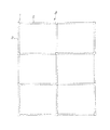
次に、本発明の最も好ましい実施形態について図を参照して具体的に説明する。本実施形態は、鉄骨造3階建てのラーメン構造体を有する工業化住宅における補強構造の例であり、図1はラーメン構造体の平面的グリッド構成を示す図、図2はラーメン構造体の全体構成を示す斜視図、図3、図4はラーメン構造体を構成する柱と大梁の接合状態を示す図、図5はダンパーの構成を示す図、図6はダンパーを付加した状態の柱と大梁の接合部を示す図である。
Next, the most preferred embodiment of the present invention will be specifically described with reference to the drawings. The present embodiment is an example of a reinforcing structure in an industrialized house having a steel frame three-story ramen structure, FIG. 1 is a diagram showing a planar grid configuration of the ramen structure, and FIG. 2 is an overall configuration of the
図1、2に示すように、住宅Aは、妻方向が2スパンで合計6つの平面グリッドからなる3層のラーメン構造体からなる。図2に示すように、住宅Aのラーメン構造体は、1層から3層まで連続した通し柱形式の複数の柱1と、各階層において隣接する柱1どうしを連結する複数の大梁2と、大梁2の直下に格子状に形成された鉄筋コンクリート造の基礎3とで構成されている。なお、柱脚部は特開平01−203522号公報に開示された露出型固定柱脚工法にて基礎に接合されている。
As shown in FIGS. 1 and 2, the house A is composed of a three-layered ramen structure composed of a total of six planar grids with two spans in the wife direction. As shown in FIG. 2, the ramen structure of the house A includes a plurality of columns 1 in the form of continuous columns from one layer to three layers, a plurality of
このラーメン構造体を構築したのち、相対する大梁2の間に小梁を適宜架け渡した上でALC(軽量気泡コンクリート)からなる床パネルを梁の上フランジに載置して床が構成され、外周部の大梁2にALCからなる壁パネルを取り付けることによって外壁が構成されて住宅Aの躯体が完成する。
After constructing this ramen structure, a floor is constructed by placing a small beam between opposing
図3、図4に示すように、柱1は、外形寸法が150mm角の角形鋼管からなる通し柱となっており、柱脚プレート1aの接合部から中途部分に形成された柱・柱接合部1bまでの部分である下部柱1cは、22mmの肉厚を有する横断面内に溶接による継目が存在しない角型鋼管であり、長さ方向についても接合部を有することなく構成されている。下部柱1cより上部の柱を構成する上部柱1dは、外形寸法が下部柱1cと同一の150mm角ではあるが下部柱1cよりも薄い4.5mm乃至6.0mmの肉厚を有する角形鋼管で構成されている。 As shown in FIGS. 3 and 4, the column 1 is a through column made of a square steel pipe having an outer dimension of 150 mm square, and a column / column junction 1b formed in the middle of the junction of the column base plate 1a. The lower column 1c, which is a part up to, is a square steel pipe having no welded seam in a cross section having a thickness of 22 mm, and is configured without a joint portion in the length direction. The upper column 1d constituting the column above the lower column 1c is a rectangular steel pipe having a wall thickness of 4.5 mm to 6.0 mm, which is 150 mm square whose outer dimensions are the same as the lower column 1c, but thinner than the lower column 1c. It is configured.
柱1は、各階層の標準的な階高(大梁上端面間の離間寸法)が2870mmとなるように大梁2の接合レベルが設定されており、柱1の各面には大梁2の接合プレート2dの孔2eに対応するようにネジが切られた孔1fが穿たれて各階の大梁2との接合部1eが形成されている。大梁2の孔2eと同様に、上部2段と最下段の計6個の孔1fが、大梁2と接合するボルト4を螺入する孔であり、下から2段目の孔2個は位置合わせ用の孔である。柱・柱接合部1bは、特開平6−180026号公報、特開平8−60740号公報等に記載された公知の接合部構造によって3階の大梁2との接合部1eの上方に形成されている。
The column 1 has a joint level of the
柱1の各面において、2階の大梁2との接合部1eから下方向及び上方向に所定寸法離間した位置と、3階の大梁2との接合部1eの下方向に所定方向離隔した位置には、後述するダンパー5をボルト接合する為のネジが切られた複数のボルト孔が穿たれてダンパー5との接合部1gが形成されている。下部柱1cはシームレスパイプで構成されているのでダンパー5との接合部1gはボルト孔を穿設するだけで容易に形成することができ接合の高さを自由に設定することができる。
On each surface of the pillar 1, a position that is spaced apart from the joint 1 e with the second-
大梁2はH形鋼からなり、全ての階層における全ての大梁2は梁成が250mm、上下のフランジ2a、2bの幅が125mm、厚みが9mm、ウェブ2cの厚みが6mmに統一されている。大梁2の柱1との接合部は、大梁2の両端部に溶接された接合プレート2dによって構成され、接合プレート2dには、横方向には中心から左右対称に2列、縦方向には等間隔に4段、同一径の孔2eが計8箇所穿たれている。孔2eのうち上部2段と最下段の計6個の孔が柱1との接合に使用するボルト4を挿通する為の孔である。なお、下から2段目の孔2個は接合作業の際「シノ」を挿し込んで位置合わせを行う為の孔であり、柱1と大梁2との接合には使用しない。大梁2の上下フランジ2a、2bには各種部材をボルト固定する為の孔群2a1、2b1が柱1に接合した状態でモジュールに基づく基準線を中心にして穿たれている。この構成は寸法も含め全ての階層の全ての大梁2に共通している。
The
図5に示すダンパー5は、低降伏点鋼からなる芯部材5aと芯部材5aに圧縮力が作用した際の座屈を防止する為の座屈防止部材5bとからなる。芯部材5aは、棒板状の本体5a1と、本体の一端に溶接され梁フランジに接合される第1接合プレート5a2と、本体の他端に溶接され柱に接合される第2接合プレート5a3からなる。座屈防止部材5bは一般構造用圧延鋼材からなる一対の平板5b1と一対の側板5b2を断面がロ字状となるようにボルト5b3で締結して構成され、中央の空隙部分に芯部材5aの本体5a1が配されている。座屈防止部材5bで芯部材5aの座屈が抑制されることにより、ダンパー5は引張力とともに圧縮力をも負担することができ、正負いずれの水平力に対しても抵抗することができる。
The
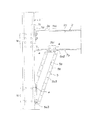
図6に示すように、ダンパー5は、方杖型であり、第1接合プレート5a2を大梁2の下フランジ2aにボルト接合し、第2接合プレート5a3を柱1のダンパーとの接合部1gにボルト接合することによって、大梁2と柱1に跨って配置されている。大梁2に対しては、大梁2の下フランジ2bにモジュールに基づいて設けられた複数の孔群のうち、柱1の配置の基準となる基準線(通り芯)から305mm(モジュールの1倍)の位置にある孔群2a1を利用してボルト接合されている。本実施例においてダンパー5は、柱1と大梁2に接合した状態でダンパー5の中心線と水平面とのなす角度が70度となるように構成されている。
As shown in FIG. 6, the
なお、ダンパー5と大梁2との接合位置はここに限定はされず、柱1の配置の基準となる基準線(通り芯)からモジュールの整数倍の位置にある孔群を利用してダンパー5を接合することができる。例えば、大梁2との接合位置を固定してダンパー5との接合部1gを大梁2との接合部から離隔させていくと大梁2の長手方向とのなす角度が直角に近づいていき、大梁2の補剛効果を高めることができる。また、ダンパー5と大梁2の長手方向とのなす角度を変えずにダンパー5との接合部1gを大梁2との接合部から離隔させるとともに大梁2との接合位置をスパン中央方向に移動させた場合も、大梁2に作用する曲げモーメントを小さくすることができ、補強という点では有効である。しかし、窓や室内空間のレイアウト上の制約を極力小さくする為にはこの位置で大梁2に接合するのが好ましい。
In addition, the joining position of the
1本の柱1に対してダンパーが取り付け可能な位置(レベル)は、2階の大梁2のレベルでは、大梁2の上フランジ2aと上フランジ2a、3階の大梁2のレベルでは下フランジ2bであり、夫々のレベルで4面(X、Y夫々の方向について2ヶずつ)取り付けることが可能である。
The position (level) at which the damper can be attached to one column 1 is the upper flange 2a and upper flange 2a of the
ダンパー5は、住宅Aに求められる構造耐力が得られるように適宜配置されるが、その際、室内の空間への突出がない位置あるいは突出の影響が少ない位置に設けるのが好ましい。例えば、住宅Aの外周(外壁)に沿った大梁2、間仕切壁の位置に一致する大梁2、物入や押入等の収納の内部に位置する大梁2に設置するのが好ましい。また、室内空間に突出する場合は天井側(大梁2の下フランジ2b側)に取り付けてダンパー5の形状に応じて内部壁(木工事で形成される室内側の壁)をふかして仕上げるのが好ましい。壁に斜めの突出部分が形成されるが、背の高い家具等を壁際に設置するなどしない限りは生活上さほど問題とならない。
The
上記構成によれば、ごくまれに発生する巨大地震により想定を超える水平力が作用した場合、柱1と大梁2との接合部に先行してダンパー5が塑性変形域に達する。そして、更に大きな水平力が作用しダンパー5が破断して耐力要素として機能しなくなったとしても、柱1と大梁2との接合部で水平力を負担することができるので、巨大地震後の余震等によって住宅Aが崩壊することがない。
According to the said structure, when the horizontal force exceeding assumption is acted on by the huge earthquake which generate | occur | produces very rarely, the
また、ダンパー5のない一般的なラーメン構造体に比べて大梁2に作用する最大の曲げモーメントを小さくすることができ、しかもそれを大梁2の母材部分に作用させることができるので構造耐力上有利となる。例えばスパンが4270mmの場合、大梁2に作用する曲げモーメントはダンパー5接合部で最大となりその値はダンパー5を設置しない状態での2階の大梁2の端部に作用する曲げモーメントの凡そ89%となる。
Further, the maximum bending moment acting on the
また、1本の柱1に対し同一レベルで最大4面にダンパーが接合できるので、住宅Aに求められる構造耐力に応じて設置位置や数を容易に調整することができる。 In addition, since dampers can be joined to a maximum of four surfaces at the same level with respect to one pillar 1, the installation position and number can be easily adjusted according to the structural strength required for the house A.
また、前記柱1のうち下部柱1bを横断面内に溶接による継目が存在しないシームレスパイプで構成したので、ダンパー5との接合部にジョイントボックス等を溶接する必要がなく、溶接欠陥によって性能が低下する可能性がない。従って、耐震性能に対する信頼性を高めることができる。また、シームレスパイプで構成された範囲内においては、柱1の側面の任意の位置にボルト孔を設けるだけでダンパー5を接合することができるので、ダンパー5の接合高さの設定を、住宅Aに求められる構造耐力や有効な室内空間の広さ等に応じて容易に変更できる。
In addition, since the lower column 1b of the columns 1 is composed of a seamless pipe with no welded seam in the cross section, it is not necessary to weld a joint box or the like to the joint portion with the
なお、必要に応じて3階の大梁2のレベルにおいて上フランジ2aに取り付け可能にしてもよいし、R階の大梁2のレベルにおいて下フランジ2bに取り付け可能としてもよい。この場合、柱1の全てを長さ方向に継ぎ目のない1本のシームレスパイプで構成するのが好ましい。
If necessary, it may be attached to the upper flange 2a at the level of the
本発明は、柱と梁が剛接合されたラーメン構造体全般に適用が可能である。 The present invention can be applied to all rigid frame structures in which columns and beams are rigidly connected.
A…住宅
1…柱
1a…柱脚プレート
1b…柱・柱接合部
1c…下部柱
1d…上部柱
1e…大梁との接合部
1f…孔
1g…ダンパーとの接合部
2…大梁
2a…上フランジ
2a1…孔群
2b…下フランジ
2b1…孔群
2c…ウェブ
2d…接合プレート
2e…孔
3…基礎
4…ボルト
5…ダンパー
5a…芯部材
5a1…本体
5a2…第1接合プレート
5a3…第2接合プレート
5b…座屈防止部材
5b1…平板
5b2…側板
5b3…ボルト
A ... House 1 ... Column 1a ... Column base plate 1b ... Column / column joint 1c ... Lower column 1d ... Upper column 1e ... Joint 1f with large beam ... Hole 1g ... Joint 2 with
Claims (2)
Priority Applications (1)
| Application Number | Priority Date | Filing Date | Title |
|---|---|---|---|
| JP2008085105A JP5096979B2 (en) | 2008-03-28 | 2008-03-28 | Reinforcement structure of ramen structure |
Applications Claiming Priority (1)
| Application Number | Priority Date | Filing Date | Title |
|---|---|---|---|
| JP2008085105A JP5096979B2 (en) | 2008-03-28 | 2008-03-28 | Reinforcement structure of ramen structure |
Related Child Applications (1)
| Application Number | Title | Priority Date | Filing Date |
|---|---|---|---|
| JP2012207407A Division JP2013032696A (en) | 2012-09-20 | 2012-09-20 | Reinforcement structure of rigid frame structure |
Publications (2)
| Publication Number | Publication Date |
|---|---|
| JP2009235827A JP2009235827A (en) | 2009-10-15 |
| JP5096979B2 true JP5096979B2 (en) | 2012-12-12 |
Family
ID=41250105
Family Applications (1)
| Application Number | Title | Priority Date | Filing Date |
|---|---|---|---|
| JP2008085105A Active JP5096979B2 (en) | 2008-03-28 | 2008-03-28 | Reinforcement structure of ramen structure |
Country Status (1)
| Country | Link |
|---|---|
| JP (1) | JP5096979B2 (en) |
Cited By (1)
| Publication number | Priority date | Publication date | Assignee | Title |
|---|---|---|---|---|
| CN109057487A (en) * | 2018-08-18 | 2018-12-21 | 张文英 | Steel frame construction stand shock-resistant structure |
Families Citing this family (1)
| Publication number | Priority date | Publication date | Assignee | Title |
|---|---|---|---|---|
| JP5769458B2 (en) * | 2011-03-14 | 2015-08-26 | 旭化成ホームズ株式会社 | Reinforcement structure of frame |
Family Cites Families (1)
| Publication number | Priority date | Publication date | Assignee | Title |
|---|---|---|---|---|
| JPS60246941A (en) * | 1984-05-18 | 1985-12-06 | 株式会社 中山製鋼所 | Assembled house converted industrial structure |
-
2008
- 2008-03-28 JP JP2008085105A patent/JP5096979B2/en active Active
Cited By (2)
| Publication number | Priority date | Publication date | Assignee | Title |
|---|---|---|---|---|
| CN109057487A (en) * | 2018-08-18 | 2018-12-21 | 张文英 | Steel frame construction stand shock-resistant structure |
| CN109057487B (en) * | 2018-08-18 | 2020-07-31 | 青岛义和钢构有限公司 | Steel frame construction stand shock-resistant structure |
Also Published As
| Publication number | Publication date |
|---|---|
| JP2009235827A (en) | 2009-10-15 |
Similar Documents
| Publication | Publication Date | Title |
|---|---|---|
| JP4931490B2 (en) | Structure reinforcement structure and method of reinforcement | |
| JP2013032696A (en) | Reinforcement structure of rigid frame structure | |
| JP5124146B2 (en) | Seismic control building | |
| JP5096979B2 (en) | Reinforcement structure of ramen structure | |
| JP6469429B2 (en) | Truss beam frame | |
| JP5437009B2 (en) | Reinforcement structure of frame | |
| JP5400283B2 (en) | Building unit connection structure and unit building | |
| JP5967642B2 (en) | Building reinforcement structure | |
| JP5940416B2 (en) | building | |
| JP2001303663A (en) | Narrow wall panel structure, portal frame structure and wooden building | |
| JP5558071B2 (en) | Reinforcement structure of frame | |
| JP2006052543A (en) | Structure of extension of existing reinforced concrete building | |
| JP5583381B2 (en) | Reinforcement structure of frame | |
| JP6414877B2 (en) | Reinforcement structure and building | |
| KR102181525B1 (en) | Multi floor tower type fusion Hanok framework made of steel beam | |
| CN112252473A (en) | Full-assembly house structure system | |
| JP2011074732A (en) | Frame reinforcement structure | |
| JP4772308B2 (en) | How to build a unit building | |
| JP5583314B2 (en) | Joint structure of column and beam | |
| JP5004434B2 (en) | Steel house | |
| JP2007039995A (en) | Seismically retrofitting frame for existing building | |
| JP5649766B2 (en) | Joint structure of column and beam | |
| JP2015117534A (en) | Bearing wall of combinedly using face bar and brace | |
| JP3517352B2 (en) | Apartment house | |
| CN213868288U (en) | Full-assembly house structure system |
Legal Events
| Date | Code | Title | Description |
|---|---|---|---|
| RD04 | Notification of resignation of power of attorney |
Free format text: JAPANESE INTERMEDIATE CODE: A7424 Effective date: 20090807 |
|
| A621 | Written request for application examination |
Free format text: JAPANESE INTERMEDIATE CODE: A621 Effective date: 20110121 |
|
| A977 | Report on retrieval |
Free format text: JAPANESE INTERMEDIATE CODE: A971007 Effective date: 20120822 |
|
| TRDD | Decision of grant or rejection written | ||
| A01 | Written decision to grant a patent or to grant a registration (utility model) |
Free format text: JAPANESE INTERMEDIATE CODE: A01 Effective date: 20120828 |
|
| A01 | Written decision to grant a patent or to grant a registration (utility model) |
Free format text: JAPANESE INTERMEDIATE CODE: A01 |
|
| A61 | First payment of annual fees (during grant procedure) |
Free format text: JAPANESE INTERMEDIATE CODE: A61 Effective date: 20120921 |
|
| R150 | Certificate of patent or registration of utility model |
Ref document number: 5096979 Country of ref document: JP Free format text: JAPANESE INTERMEDIATE CODE: R150 Free format text: JAPANESE INTERMEDIATE CODE: R150 |
|
| FPAY | Renewal fee payment (event date is renewal date of database) |
Free format text: PAYMENT UNTIL: 20150928 Year of fee payment: 3 |
|
| S531 | Written request for registration of change of domicile |
Free format text: JAPANESE INTERMEDIATE CODE: R313531 |
|
| R350 | Written notification of registration of transfer |
Free format text: JAPANESE INTERMEDIATE CODE: R350 |