JP5095723B2 - Remotely adjustable tissue displacement device - Google Patents
Remotely adjustable tissue displacement device Download PDFInfo
- Publication number
- JP5095723B2 JP5095723B2 JP2009504485A JP2009504485A JP5095723B2 JP 5095723 B2 JP5095723 B2 JP 5095723B2 JP 2009504485 A JP2009504485 A JP 2009504485A JP 2009504485 A JP2009504485 A JP 2009504485A JP 5095723 B2 JP5095723 B2 JP 5095723B2
- Authority
- JP
- Japan
- Prior art keywords
- drive member
- actuator
- magnet
- drive
- attachment
- Prior art date
- Legal status (The legal status is an assumption and is not a legal conclusion. Google has not performed a legal analysis and makes no representation as to the accuracy of the status listed.)
- Active
Links
- QXDDGAFPLOSEFV-DJWKRKHSSA-N C/C=C\C1C#CCC1 Chemical compound C/C=C\C1C#CCC1 QXDDGAFPLOSEFV-DJWKRKHSSA-N 0.000 description 1
Images


Classifications
-
- A—HUMAN NECESSITIES
- A61—MEDICAL OR VETERINARY SCIENCE; HYGIENE
- A61B—DIAGNOSIS; SURGERY; IDENTIFICATION
- A61B17/00—Surgical instruments, devices or methods, e.g. tourniquets
- A61B17/56—Surgical instruments or methods for treatment of bones or joints; Devices specially adapted therefor
- A61B17/58—Surgical instruments or methods for treatment of bones or joints; Devices specially adapted therefor for osteosynthesis, e.g. bone plates, screws, setting implements or the like
- A61B17/68—Internal fixation devices, including fasteners and spinal fixators, even if a part thereof projects from the skin
- A61B17/80—Cortical plates, i.e. bone plates; Instruments for holding or positioning cortical plates, or for compressing bones attached to cortical plates
- A61B17/8061—Cortical plates, i.e. bone plates; Instruments for holding or positioning cortical plates, or for compressing bones attached to cortical plates specially adapted for particular bones
- A61B17/8076—Cortical plates, i.e. bone plates; Instruments for holding or positioning cortical plates, or for compressing bones attached to cortical plates specially adapted for particular bones for the ribs or the sternum
-
- A—HUMAN NECESSITIES
- A61—MEDICAL OR VETERINARY SCIENCE; HYGIENE
- A61B—DIAGNOSIS; SURGERY; IDENTIFICATION
- A61B17/00—Surgical instruments, devices or methods, e.g. tourniquets
- A61B17/56—Surgical instruments or methods for treatment of bones or joints; Devices specially adapted therefor
-
- A—HUMAN NECESSITIES
- A61—MEDICAL OR VETERINARY SCIENCE; HYGIENE
- A61B—DIAGNOSIS; SURGERY; IDENTIFICATION
- A61B17/00—Surgical instruments, devices or methods, e.g. tourniquets
-
- A—HUMAN NECESSITIES
- A61—MEDICAL OR VETERINARY SCIENCE; HYGIENE
- A61B—DIAGNOSIS; SURGERY; IDENTIFICATION
- A61B17/00—Surgical instruments, devices or methods, e.g. tourniquets
- A61B17/02—Surgical instruments, devices or methods, e.g. tourniquets for holding wounds open; Tractors
- A61B17/025—Joint distractors
-
- A—HUMAN NECESSITIES
- A61—MEDICAL OR VETERINARY SCIENCE; HYGIENE
- A61B—DIAGNOSIS; SURGERY; IDENTIFICATION
- A61B17/00—Surgical instruments, devices or methods, e.g. tourniquets
- A61B17/56—Surgical instruments or methods for treatment of bones or joints; Devices specially adapted therefor
- A61B17/58—Surgical instruments or methods for treatment of bones or joints; Devices specially adapted therefor for osteosynthesis, e.g. bone plates, screws, setting implements or the like
- A61B17/68—Internal fixation devices, including fasteners and spinal fixators, even if a part thereof projects from the skin
- A61B17/80—Cortical plates, i.e. bone plates; Instruments for holding or positioning cortical plates, or for compressing bones attached to cortical plates
- A61B17/8004—Cortical plates, i.e. bone plates; Instruments for holding or positioning cortical plates, or for compressing bones attached to cortical plates with means for distracting or compressing the bone or bones
- A61B17/8009—Cortical plates, i.e. bone plates; Instruments for holding or positioning cortical plates, or for compressing bones attached to cortical plates with means for distracting or compressing the bone or bones the plate having a ratchet
-
- A—HUMAN NECESSITIES
- A61—MEDICAL OR VETERINARY SCIENCE; HYGIENE
- A61B—DIAGNOSIS; SURGERY; IDENTIFICATION
- A61B17/00—Surgical instruments, devices or methods, e.g. tourniquets
- A61B2017/00367—Details of actuation of instruments, e.g. relations between pushing buttons, or the like, and activation of the tool, working tip, or the like
- A61B2017/00407—Ratchet means
-
- A—HUMAN NECESSITIES
- A61—MEDICAL OR VETERINARY SCIENCE; HYGIENE
- A61B—DIAGNOSIS; SURGERY; IDENTIFICATION
- A61B17/00—Surgical instruments, devices or methods, e.g. tourniquets
- A61B2017/00367—Details of actuation of instruments, e.g. relations between pushing buttons, or the like, and activation of the tool, working tip, or the like
- A61B2017/00411—Details of actuation of instruments, e.g. relations between pushing buttons, or the like, and activation of the tool, working tip, or the like actuated by application of energy from an energy source outside the body
-
- A—HUMAN NECESSITIES
- A61—MEDICAL OR VETERINARY SCIENCE; HYGIENE
- A61B—DIAGNOSIS; SURGERY; IDENTIFICATION
- A61B17/00—Surgical instruments, devices or methods, e.g. tourniquets
- A61B2017/00831—Material properties
- A61B2017/00867—Material properties shape memory effect
-
- A—HUMAN NECESSITIES
- A61—MEDICAL OR VETERINARY SCIENCE; HYGIENE
- A61B—DIAGNOSIS; SURGERY; IDENTIFICATION
- A61B17/00—Surgical instruments, devices or methods, e.g. tourniquets
- A61B2017/00982—General structural features
- A61B2017/00991—Telescopic means
-
- A—HUMAN NECESSITIES
- A61—MEDICAL OR VETERINARY SCIENCE; HYGIENE
- A61B—DIAGNOSIS; SURGERY; IDENTIFICATION
- A61B17/00—Surgical instruments, devices or methods, e.g. tourniquets
- A61B17/56—Surgical instruments or methods for treatment of bones or joints; Devices specially adapted therefor
- A61B17/58—Surgical instruments or methods for treatment of bones or joints; Devices specially adapted therefor for osteosynthesis, e.g. bone plates, screws, setting implements or the like
- A61B17/68—Internal fixation devices, including fasteners and spinal fixators, even if a part thereof projects from the skin
- A61B2017/681—Alignment, compression, or distraction mechanisms
Description
本発明は、一般的に、動物の1又は複数の骨など、体内の組織を変位させる装置に関する。より詳しくは、本発明は、体外から遠隔的に調整して、拡張及び/又は収縮させることができる、患者内のインプラントに関する。 The present invention relates generally to devices for displacing tissue in the body, such as one or more bones of an animal. More particularly, the present invention relates to an implant within a patient that can be remotely adjusted from outside the body and expanded and / or contracted.
例えば、Synthes, Inc.社から登録商標VEPTR(Vertically Expandable Prosthetic Titanium Rib)システムの名称の下で商業的に入手可能な、拡張可能なインプラントは、患者の体内の骨を変位するために使用されている。例えば、重度の脊髄奇形を有する幼児は、しばしば、そうしたインプラントを肋骨、背骨、及び/又は、骨盤に取り付けて使用する。インプラントは、通常、6ヶ月毎などの一定の間隔で、小さな皮膚の切開を通して調整される。しかしながら、調整は、しばしば、全身麻酔と、調整処置から回復するための入院とを必要とし、また、感染症のリスクを導入する。 For example, an expandable implant, commercially available under the name of the registered trademark VEPTR (Vertically Expandable Prosthetic Titanium Rib) system from Synthes, Inc., is used to displace bones in a patient's body. Yes. For example, infants with severe spinal malformations often use such implants attached to the ribs, spine, and / or pelvis. Implants are usually adjusted through small skin incisions at regular intervals, such as every six months. However, adjustment often requires general anesthesia and hospitalization to recover from the adjustment procedure and introduces a risk of infection.
(関連出願)
本願は、2006年4月6日に出願された、発明の名称を「遠隔調整可能な拡張装置("REMOTELY ADJUSTABLE EXPANDABLE DEVICE")」とする、米国仮特許出願第60/790,589号、及び、2006年11月11日に出願された、発明の名称を「遠隔調整可能な骨変位装置("REMOTELY ADJUSTABLE BONE DISPLACEMENT DEVICE")」とする、米国仮特許出願第60/866,739号を基礎とする優先権を主張し、これら両方の出願をここで参照によって完全に引用する。
(Related application)
This application is filed on Apr. 6, 2006, US Provisional Patent Application No. 60 / 790,589, entitled “REMOTELY ADJUSTABLE EXPANDABLE DEVICE”, and Based on US Provisional Patent Application No. 60 / 866,739, filed on November 11, 2006, with the name of the invention "Remotely Adjustable Bone Displacement Device" Both of which are hereby fully incorporated by reference.
概して言えば、組織を移動させる装置、例えば、骨を変位させるインプラントが提供される。装置は、2つの細長い部材を変位可能に具備し、好ましくは、互いに入子式に変位可能になっており、装置の長さに対して拡張及び収縮する。駆動部材は、回転して装置を拡張及び/又は収縮でき、好ましくは、磁気アクチュエータによって回転する。磁気アクチュエータは、好ましくは、外部磁場によって回転可能になっている。より詳しくは、患者の体外の磁場を利用して、患者の体内のインプラントを拡張及び/又は収縮させることができる。 Generally speaking, a device for moving tissue, for example, an implant for displacing bone, is provided. The device comprises two elongate members displaceably, preferably telescopingly displaceable from each other and expands and contracts with respect to the length of the device. The drive member can rotate to expand and / or contract the device and is preferably rotated by a magnetic actuator . The magnetic actuator is preferably rotatable by an external magnetic field. More specifically, a magnetic field outside the patient's body can be utilized to expand and / or contract the implant within the patient's body.
1つの実施形態による装置は、近位端と遠位端とを有する2つの細長い部材を有し、駆動部材は、細長い部材の1つに対して、機能的に関連して回転可能になっている。磁気アクチュエータ組立体は、駆動部材と関連して、磁気アクチュエータが回転するとき、駆動部材も回転し、これが、2つの細長い部材を互いに動かさせる。磁気アクチュエータ組立体は、好ましくは、外部磁場によって回転可能である。 An apparatus according to one embodiment has two elongate members having a proximal end and a distal end, and the drive member is functionally related and rotatable relative to one of the elongate members. Yes. The magnetic actuator assembly is associated with the drive member so that when the magnetic actuator rotates, the drive member also rotates, causing the two elongate members to move relative to each other. The magnetic actuator assembly is preferably rotatable by an external magnetic field.
別の実施形態による装置は、2つの骨取付部材と、変位機構とを備え、皮膚を通して伝達される磁場によってアクセス可能な位置に、皮下移植されるように構成されている。装置は、被動部材と、骨取付部材の間に結合された回転可能な駆動部材と、駆動部材に結合された唇部と、反対方向に行ったり来たり回転可能な磁石と、磁石の行ったり来たりの回転に際して、唇部に対して、接触し、ぶつかり、又は衝突する、磁石に結合された駆動歯とを具備している。 An apparatus according to another embodiment comprises two bone attachment members and a displacement mechanism and is configured to be implanted subcutaneously at a location accessible by a magnetic field transmitted through the skin. The device includes a driven member, a rotatable drive member coupled between the bone attachment members, a lip coupled to the drive member, a magnet that can be rotated back and forth, and a magnet It includes a drive tooth coupled to a magnet that contacts, collides with, or collides with the lips during the upcoming rotation.
代替的な実施形態による装置は、2つの骨取付部材を有する骨変位装置と、一方の骨取付部材に結合された駆動部材と、第2の骨取付部材に結合された回転可能な駆動部材とを備えている。好ましくは、駆動部材と被動部材とは、ねじを介して関連し、第2の骨取付部材に対して軸線方向に駆動部材を移動させる。従って、駆動部材が変位方向に回転する際には、骨取付部材が変位できる。また、装置は、回転可能なアクチュエータと、アクチュエータと駆動部材との間で機能するクラッチ機構とを具備してもよく、反対方向に行ったり来たりとアクチュエータが回転する際には、駆動部材は変位方向へ前進する。好ましくは、回転可能な磁石が設けられ、磁石の回転は、アクチュエータを行ったり来たりと回転させる。 An apparatus according to an alternative embodiment includes a bone displacement device having two bone attachment members, a drive member coupled to one bone attachment member, and a rotatable drive member coupled to a second bone attachment member. It has. Preferably, the drive member and the driven member are related via a screw and move the drive member in the axial direction relative to the second bone attachment member. Therefore, when the drive member rotates in the displacement direction, the bone attachment member can be displaced. The apparatus may also include a rotatable actuator and a clutch mechanism that functions between the actuator and the drive member. When the actuator rotates back and forth, the drive member Advance in the direction of displacement. Preferably, a rotatable magnet is provided, and the rotation of the magnet rotates the actuator back and forth.
好ましい実施形態による装置によれば、直接的な実際の磁力よりもむしろ、磁気ロータの変化する磁場を使用して、駆動部材を回転させる。例えば、駆動部材又は駆動部材を回転させるアクチュエータは、振動し、そうした回転のために、衝突モーメントを頼りにする。 According to the device according to the preferred embodiment, the driving member is rotated using the changing magnetic field of the magnetic rotor, rather than the actual magnetic force directly. For example, a drive member or an actuator that rotates the drive member vibrates and relies on a collision moment for such rotation.
装置は、構成、要素の組合せ、及び部品の配置の特徴を備え、これらは、以下に明らかにされるけれども、本発明の範囲は、そうした特徴、要素の組合せ、又は部品の配置によって限定されるべきではない。 The apparatus comprises features of configuration, combination of elements, and arrangement of parts, which will be clarified below, but the scope of the invention is limited by such characteristics, combination of elements, or arrangement of parts. Should not.
従って、本発明は、複数の要素と、1又は複数のそうした要素の互いの関係とを備え、また、構成の特徴を実現した装置、要素の組合せ、及び部品の配置であって、そうした段階を行うのに適したもの、以下の詳細な説明において例示されたすべてのもの、及び本発明の範囲は、特許請求の範囲に示されている。 Accordingly, the present invention comprises a plurality of elements and one or more of such elements' relationships with each other, and is a device, combination of elements, and arrangement of parts that implements the features of the arrangement, and includes such steps. What is suitable to do, all that is illustrated in the following detailed description, and the scope of the invention are indicated in the claims.
装置は、以下の例示的な図面によって、さらに詳しく説明される。図面は、単なる例示であって、好ましい装置の構造を例示すると共に、単独で又は他の特徴と組み合わせて使用される、ある種の特徴を示している。本発明は、示される実施形態に制限されるべきではない。 The apparatus is described in more detail by the following exemplary drawings. The drawings are merely exemplary and illustrate certain features that may be used alone or in combination with other features, as well as illustrating the structure of the preferred device. The invention should not be limited to the embodiments shown.
以下、本発明のある種の例示的な実施形態について、添付図面を参照して説明する。一般に、そうした実施形態は、動物の体内の組織を変位させる装置に関し、非制限的な例としては、脊髄奇形をもつ人物に適用される。脊髄奇形をもった子供は、器官が混雑せずに自由に成長するために、胸郭を拡張させるように定期的に調整されるインプラントをしばしば必要とする。従って、本発明の実施形態に従って、そうしたインプラントを遠隔調整する装置を提供することは望ましい。遠隔調整とは、外科手術又はその他の侵襲性の又は非侵襲性の処置を受ける必要なく、装置を調整できる能力を称する。 Certain exemplary embodiments of the invention will now be described with reference to the accompanying drawings. In general, such embodiments relate to devices for displacing tissue in an animal's body, and as a non-limiting example, apply to a person with a spinal malformation. Children with spinal malformations often require implants that are regularly adjusted to expand the rib cage in order for the organs to grow freely without becoming congested. Accordingly, it is desirable to provide an apparatus for remotely adjusting such an implant in accordance with an embodiment of the present invention. Remote adjustment refers to the ability to adjust the device without having to undergo surgery or other invasive or non-invasive procedures.
図1〜図3及び図8〜図9を参照すると、組織を変位させるための、ある種の例示的な実施形態による装置が示されている。組織を変位させる装置100,500は、実質的に直線状であるか、曲線状であるか、又は設計事項に従って、その他の形状を有する。図示の実施形態においては、装置100,500は、好ましくは、比較的滑らかである、ロッド122,522を有する第1の部材120,520と、管状部材142,542を有する第2の部材140,540とを具備している。ロッド122,522と管状部材142,542とは、互いに選択的に変位可能であり、好ましくは、入子式に又は横方向に変位可能になっている。第1の部材120,520と第2の部材140,540とは、好ましくは、細長くて、比較的直線状又は曲線状である。さらに、駆動部材が管状部材に関連するものとして、ある種の実施形態を説明したけれども、駆動部材はロッドに関連し、逆もまた同様であることを理解されたい。
With reference to FIGS. 1-3 and FIGS. 8-9, an apparatus according to certain exemplary embodiments for displacing tissue is shown. The
好ましい実施形態によれば、装置100,500は、駆動組立体200,600を備え、第2の部材140,540に対して第1の部材120,520を変位させ、装置100,500を拡張及び/又は収縮させる。好ましくは、管状部材142,542は、内側キャビティ146,546を具備し、その中に、ロッド122,522が受け入れられる。
According to a preferred embodiment, the device 100,500 comprises a drive assembly 200,600, displaces the first member 120,520 relative to the second member 140,540, expands and expands the device 100,500. / Or shrink. Preferably, the
図示の実施形態においては、第1の部材120,520は、体内の組織に取り付けるために、第1の取付装置124,524を具備している。同様に、第2の部材140,540は、体内の組織に取り付けるために、第2の取付装置144,544を具備している。
第1及び第2の取付装置は、フック、クランプ、閉じたリング、又は、その他の機構であって、骨、例えば、肋骨に取り付けられるものである。クランプの適切な例としては、米国特許第6,126,664号に"DEVICE AND METHOD FOR LOCATING AND RESECTING BONE"が、第6,143,031に"INTERVERTEBRAL IMPLANT WITH COMPRESSIBLE SHAPED HOLLOW ELEMENT"が、第5,092,889号に"EXPANDABLE VERTICAL PROSTHETIC RIB"が、同第5,030,235号に"PROSTHETIC FIRST RIB"が、同第5,261,908号に"EXPANDABLE VERTICAL PROSTHETIC RIB"が開示されている。
In the illustrated embodiment, the
The first and second attachment devices are hooks, clamps, closed rings, or other mechanisms that attach to bone, eg, ribs. Suitable examples of clamps include “DEVICE AND METHOD FOR LOCATING AND RESECTING BONE” in US Pat. No. 6,126,664, “INTERVERTEBRAL IMPLANT WITH COMPRESSIBLE SHAPED HOLLOW ELEMENT” in US Pat. , 092, 889, "EXPANDABLE VERTICAL PROSTHETIC RIB" is disclosed, 5,030, 235 is "PROSTHETIC FIRST RIB", and 5,261,908 is "EXPANDABLE VERTICAL PROSTHETIC RIB". .
装置100,500が拡張すると、第1の部材120,520は、第2の部材140,540に対して変位して、それぞれの組織が互いに離れるように押圧される。例えば、第1の部材120,520が肋骨に取り付けられ、第2の取付装置140,540が腰部に取り付けられているならば、肋骨の骨は押し出され、脊髄奇形を修正又は治療する。
When the
次に、図1〜図3の実施形態を参照すると、駆動部材210を有する駆動組立体200が示されている。図示の通り、駆動部材210は、好ましくは、ねじ216である部分を少なくとも有する外周214を備え、好ましくは、第1の部材120のロッド122に取り付けられている。駆動部材210が回転すると、外周214のねじ216は、内側キャビティ146に接触し、内側キャビティ146は、好ましくは、ねじ付き部分148を有し、駆動部材210が、管状部材142の長さに対して移動する。同時に、駆動部材210に取り付けられている第1の部材120もまた、好ましくは、第2の部材140の内部を、より好ましくは、入子式に、第2の部材140の長さに対して移動する。さらに、駆動部材210の外周214のねじ216と、第2の部材210の内側キャビティのねじ付き部分148とは、協働して、スリップを防止し、第1の部材120と第2の部材140とを所定位置に保持する。駆動部材210はロッド122の端部に取り付けられるものとして示したけれども、駆動部材210は、ロッド122の長さに対する別の位置において、ロッド122に取り付けることもできることを理解されたい。“回転”という用語は、360゜未満の部分的な回転、360゜の完全な回転、又はそれを越える回転を包含することを理解されたい。
1-3, a
駆動部材210は、例えば図4A、図4Bに示すように、アクチュエータ300によって回転する。アクチュエータ300は、好ましくは、磁石310である磁気部材を具備し、好ましくは外部磁石活性装置400によって駆動される。図示した実施形態によるアクチュエータ300は、駆動部材210と整列され、好ましくは、同軸的であり、磁石310を具備し、好ましくは、円筒形磁石であって第1の磁極312と第2の磁極314とを有し、また、好ましくは、磁石310の回転がリング320を回転させるような、磁石310に取り付けられたリング320を有する。変形例の実施形態によるアクチュエータは、平行に配置され、好ましくは、駆動部材からオフセットしている。
The
非制限的な例としては、第1の磁極312はN極であり、第2の磁極314はS極である。磁石310が回転すると、駆動部材210は、好ましくは、所定の増分をもって、回転させられ、従って、所定の増分にて、装置100を拡張又は収縮させる。磁石310は、体外の磁場によって回転させられるので、装置100を拡張又は収縮させるために、切開又は侵襲性の処置を行う必要が解消される。遠隔調整可能な装置を提供することで、患者は、さもなくば必要となるであろう、外科手術処置から救われ、また、感染のリスクと、それに関連した入院とから救われる。さらに、整列された、好ましくは同軸的な、アクチュエータ300と駆動部材210との構成は、細い輪郭をもった実質的に幅狭の装置を提供し、患者の不快を低減し、組織への刺激が少なくなる。
As a non-limiting example, the first
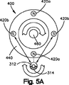
図3、図5A〜図5Dには、実施形態による外部活性装置400を示しており、好ましくは、2以上の、好ましくは、4つの磁石420a,420bを有する面440を具備し、面440に取り付けられたそれぞれの磁石は単一の磁極を有している。図3に示すように、外部活性装置400は、好ましくは、皮膚Sの上方に配置される。図示の実施形態においては、外部活性装置400は、N極を有する2つの磁石420aと、S極を有する2つの磁石420bとを具備している。N極磁石420aとS極磁石420bとは、交互に配置されている。面440が軸線Xを中心として、活性装置の棒460によって回転すると、磁場が生成される。図5A〜図5Dを参照すると、単極磁石420a,420bは、外部活性装置400が回転すると、磁石310に所望の回転が得られる。単極磁石420a,420bがアクチュエータ300に向かい又は遠ざかると、磁石420a,420bは、引力(実線の矢印)及び/又は斥力(破線)を磁石310と生成し、磁石310を回転させる。
3 and 5A-5D show an
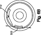
好ましくは、磁石310は、リング320に取り付けられ、磁石310の中心を延通するリングロッド326を有し、図4Bに示すように、リングタブ322を有している。リング320は、好ましくは、耐久性材料、例えば、硬質金属、より好ましくは、磁性材料ではなく、従って、外部活性装置400によって影響されない。同様に、駆動部材210も非磁性であることが好ましい。リング320と磁石310とは、好ましくは、永久的に取り付けられ、例えば、接着剤、又は、溝部と突起部などが使用される。リング320は、磁石310から離れて延びる突起部324を具備し、これを中心として、駆動部材210は回転する。
Preferably, the
図5〜図7に示した実施形態によるアクチュエータ300を参照すると、外部活性装置400によって磁石310が回転すると、リング320も回転し、リングタブ322は、駆動部材210の歯212に接触して押圧し、駆動部材210を回転させる。アクチュエータ300は、磁石310の連続する回転と共に、駆動部材210に連続的な回転を提供し、滑らかで連続的な、ロッド120の変位を提供する。代わりに、駆動部材210は、より詳しくは後述するように、変化する力又は振動の増分において回転し、駆動部材210を回転させるのに必要なトルクを得る。
Referring to the
1つの実施形態による装置によれば、アクチュエータ300は、駆動部材210を一方の方向へ回転させることで装置を拡張させ、また、反対の方向に回転させるとき、装置100を収縮させる。代わりに、アクチュエータ300は、駆動部材210を一方向に回転させ、収縮を許容せずに、装置100を拡張させる。アクチュエータと駆動組立体200との間の関係については、その他の任意的要素も利用可能である。
According to the device according to one embodiment, the
駆動部材210は、好ましくは、静的トルク、すなわち、磁石310が回転するときのアクチュエータ300の回転力が、仕事トルク、すなわち、駆動部材210を回転させるのに必要な回転トルクに比べて大きいならば、回転できる。様々な要因は、インプラントの荷重、ねじのピッチ、摩擦などの仕事トルクに影響する。静的トルクは、様々な要因に依存し、例えば、非限定的な例としては、アクチュエータ300と外部活性装置400との間の距離、及び、磁石の材料特性に依存する。従って、静的トルクは、製造中に事前に決定される。いったん、仕事トルクが静的トルクを越えると、アクチュエータ300は駆動部材210を回転させなくなり、磁石310を回転をやめて、好ましくは、リングタブ322は歯212に近接する。次に、磁石310は、反対方向に回転し、リングタブ322は、好ましくは、約180゜、歯212から離れて回転する。好ましくは、磁石310の回転の停止と、続く反対方向への回転は、比較的迅速に生じ、より好ましくは、磁石310は、歯122に接触するリングタブ322に跳ね返るように見える。他方において、活性装置400は、好ましくは、振動せずに、一定方向に回転を続ける。歯212から遠ざかる磁石310の回転の度合いは、例えば、磁石310又はアクチュエータ300の磁極の数によって、決定される。従って、リングタブ322は、180゜の回転角度にわたって加速され、従って、大きな静止トルクを発生させる。様々な要因、例えば、磁気材料、質量、直径、活性装置の速度などが、静止トルクに影響する。そうした効果は、回転するリングタブ322の繰り返しの衝撃のために、“大ハンマー”の効果と称される。そうした関係は、図6A〜図6Cに示され、リングタブ322は、歯322からさらに遠のくように引っ込んで、より大きな回転角度を生じ、従って、より大きな静止トルクを生じる。従って、駆動部材210に作用するトルクは、回転磁石によって作用する直接トルクに比べて、実質的に大きくなる。好ましくは、そうした静止トルクは、2〜15倍、より好ましくは、約10倍、回転磁石310の静止トルクに比べて大きい。
The
図2Aに示した実施形態においては、アクチュエータ300は、片端にてリング320に取り付けられた磁石310と、好ましくは、磁石310がリング320から離間するのを防ぐような反対端部の端部片330とを具備している。さらに、アクチュエータ300は、軸線、例えば、磁石310及びリング320が回転する中心となる軸340を具備し、軸は、好ましくは、リング320と駆動部材210との間に、また、磁石310と端部片330との間に、隙間と比較的低い摩擦係数とを提供する。
In the embodiment shown in FIG. 2A, the
次に、図8〜図15を参照すると、ある種の実施形態の装置は、駆動組立体600によって第2の部材540の長さに対して変位可能な第1の部材520を具備し、さらに、駆動組立体600に隣接したアクチュエータ700を具備している。図示の実施形態においては、第1の部材520は、外周526を有するロッド522を具備し、これは、少なくとも部分的にねじ528を有し、また、第2の部材540は、好ましくは実質的に滑らかな内側キャビティ546を有する管状部材542を具備している。駆動組立体600は、好ましくは、略円筒形の形状で、外周614を有する、駆動部材610を具備している。駆動部材610は、内面616を備え、少なくともその一部分は、ねじ付きであり、第1の部材520のロッドの外周526と接触し、これもまた、少なくとも一部分がねじ付きであり、従って、駆動部材610をロッド522の長さに対して移動させる。好ましくは、駆動部材610は、ロッド522と同軸的に整列される。
Referring now to FIGS. 8-15, certain embodiments of the apparatus include a
様々な駆動組立体は、装置に使用できるけれども、図9〜図13には、適当な駆動組立体600の1つの実施形態を示している。図示の実施形態においては、駆動組立体600はクラッチ機構を具備し、例えば、図10〜図13に示すように、フリーホイールクラッチ620であって、1又は複数の、好ましくは複数のストッパ、例えば、ニードル又はローラ630を、外側ハウジングによって取り囲まれて有し、ハウジングは好ましくは、駆動部材610と整列され、より好ましくは同軸的に整列されている。図示の通り、フリーホイールクラッチ620は、駆動部材610を取り囲み、好ましくは駆動部材と同軸的に整列された外側ハウジング640を具備している。フリーホイールクラッチ620は、複数のニードル又はローラ630を、外側ハウジング640と駆動部材610との間に配置されて有している。図示の実施形態によるフリーホイールクラッチにおいては、外側ハウジング640は、傾斜をもった内壁626を有し、内壁626は収束壁626aを具備している。
Although various drive assemblies can be used in the apparatus, FIGS. 9-13 illustrate one embodiment of a
従って、外側ハウジング640が一方向に回転するとき、例えば、時計まわり方向に回転するとき、ニードル630は、好ましくは、転動して動き、ついには、収縮壁626aと駆動部材610の外周614との間に楔状になって、ローラ630がさらに動くのを停止させる。ローラ630が楔となって、動きを止めると、回転力は、駆動部材610に伝達され、従って、駆動部材610を回転させる。フリーホイールクラッチ640は、1又は複数のばね622を具備し、これらはニードル630を収束壁626aに向けて促す。
Thus, when the
他方において、外側ハウジング640が反対方向、つまり、反時計まわりに回転すると、ニードル630は解放されて、好ましくは、転動して動き、外側ハウジング640の発散壁626bに向かう。駆動部材610を反時計まわり方向に回転させるのに必要な仕事トルクは、好ましくは、ニードル630を動かし又は駆動部材610の外周614のまわりで転動させるのに必要な力に比べて大きい。従って、ニードル630は、駆動部材610が所定位置に維持される間、発散壁626bに向けて転動する。従って、フリーホイールクラッチ640は、ラチェット効果を提供し、そのために、駆動部材610の時計まわりの回転を提供するが、反時計まわりの回転を提供しない。図10〜図12には、9本のニードル630を示しているけれども、ニードル630の数は、設計事項として変化させることができ、所望の用途に合わせられることを理解されたい。非限定的な例としては、図13に示すように、代替的な実施形態によるフリーホイールクラッチ620は、6本のニードル630を具備している。さらに、フリーホイールクラッチ620のローラ630は、互いに等間隔に配置されているけれども、ローラは、図13に示すように、等間隔である必要はない。さらに、図示のフリーホイールの実施形態によれば、外側ハウジング640は、部分的に平坦な部分642を有し、これが、比較的細身の装置を提供し、不快感を減少させ、組織の刺激を少なくする。
On the other hand, as the
図10〜図12に示した実施形態による駆動組立体600は、フリーホイールクラッチ620から半径方向外方に延びて外周に固定されたレバー650を具備し、レバー650は、開口面656を有し、符号652で示される開口部を有する。レバー650は、好ましくは、アクチュエータ700によって変位され、アクチュエータは、好ましくは、略円筒形の形状と、半径方向外方に延びている球根状の突起部とを有してなる、回転部材730を備えている。非限定的な例としては、回転部材730は、偏心カム又は円板である。好ましい実施形態による駆動組立体600及びアクチュエータ700によれば、球根状の突起部732は、少なくとも回転部材730の一部分が、開口部656の内部にて回転するとき、開口面656に接触する。球根状の突起部732は、開口面656に接触し、これに沿って動き、レバー650は、選択的に変位する。
The
好ましくは、図9に示すように、アクチュエータ700は、磁石710、好ましくは円筒形磁石を具備し、これは、外部磁場によって回転する。図示の実施形態においては、アクチュエータ700は、非磁性の、硬質金属リング720を具備し、これは、リングタブ722を有している。例えば、アクチュエータ700は、上述した図3のアクチュエータ300と同様であり、リングタブ722は、回転部材730に接触し、アクチュエータロッド750を中心として回転部材730を押し回す。1つの実施形態によるアクチュエータ700によれば、リングタブ722が回転するとき、リングタブ722は、球根状の突起部732を押す。変形例としては、回転部材730は、リング720に向けて延びる歯734を具備し、リングタブ722が接触し、回転部材730を回転させる。そうした関係は、詳しく上述した。両方の実施形態は、“大ハンマー”の効果を提供する。変形例としては、回転部材730は、磁石710で直接回転させられ、従って、回転する磁石710と同じトルクを維持する。さらに、アクチュエータ700は、減速歯車を具備し、例えば、歯車列によって、磁石710の複数の回転が、大きなトルクの歯車の1回転をもたらす。その他の実施形態によるアクチュエータは、設計事項として、本発明の範囲に含まれることを理解されたい。
Preferably, as shown in FIG. 9, the
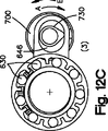
図12A〜図12Iには、フリーホイールクラッチ620が働くやり方の例を示しており、駆動組立体600と回転部材730との間の逐次的な関係が、回転部材730が時計まわりに回転するときの、位置(1)〜(9)として示される。位置(1)においては、球根状の突起部732は、レバー650の開口面656に接触している。回転部材730が回転すると、球根状の突起部732は、開口面656に沿って時計まわり方向に動き、レバー650を方向Aに押し、従って、外側ハウジング640を時計まわり方向に回転させて、続く、位置(2)及び(3)にする。図示の実施形態においては、外側ハウジング640の時計まわりの回転は、矢印645にて示すように、駆動部材610の時計まわりの回転をもたらす。
FIGS. 12A-12I show an example of how the
好ましくは、外側ハウジング640が時計まわりに回転すると、ニードル630は、外側ハウジング640の収束する内壁626aによって停止して、ついには、ニードル630は、収束する壁626aと駆動部材610の外周614との間に楔状に挟まれる。時計まわりのトルクは、好ましくは、例えば、楔状に挟まれたニードル630によって発生した摩擦力によって発生する。従って、発生するトルクが大きくなるほど、ニードル630は楔状になり、従って、駆動部材610の外周614とニードル630との間の摩擦力を高め、ニードル630が、駆動部材610の外周614に沿って、摺動又は転動することを実質的に防止する。従って、外側ハウジング640が回転し続けると、駆動部材610は、時計まわり方向に回転する。位置(3)に示した駆動組立体600は、レバー650が方向Aに最大に変位したときを示している。いったん、この位置(3)を通過すると、球根状の突起部732は、位置(4)において、開口部652のクリアランス646に進入し、回転する球根状の突起部732が時計まわり方向に回転を続けても、レバー650は変位しない。
Preferably, as the
回転部材730が時計まわりに回転し続けると、球根状の突起部732は、位置(5)に示すように、レバー650の開口面656に沿って動き、レバー650を方向Bに変位させ、ついには、レバー650は、位置(6)に示すように、方向Bの最大変位に達する。レバー650が方向Bに変位するとき、外側ハウジング640は反時計まわり方向に回転する。非限定的な例としては、外側ハウジング640が反時計まわり方向に回転すると、ニードル630は、外側ハウジング640における発散壁626bに向けて転動することができる。従って、外側ハウジング640は、反時計まわり方向に回転し、駆動部材610の回転をもたらさずに、従って、好ましくは、ラチェット作用を提供する。
As the rotating
いったん、レバー650が方向Bの最大変位に達すると、球根状の突起部732は、好ましくは、開口部652のクリアランス647に進入し、球根状の突起部732が時計まわり方向に回転を続けると、位置(7)〜(8)に示すように、レバー650は変位しない。図12に示した実施形態においては、いったん位置(9)に達すると、球根状の突起部732は、360゜回転し、位置(1)に復帰し、工程は、駆動部材610の所望の回転に達するまで繰り返され、従って、装置500に所望の拡張又は収縮が得られる。磁石は、反対方向に回転してもよいことを理解されたい。
Once the
従って、駆動組立体600は、好ましくは、ラチェット作用を提供し、そのために、駆動部材610を一方向に回転させ、反対方向に回転させず、レバー650は、方向A及びBに行き来して変位する。
Thus, the
図14を参照すると、駆動組立体600とアクチュエータ700との協調は、回転磁石710又は回転要素730のトルクに比べて、駆動部材610に大きなトルクを提供する。
角度αが小さくなるほど、距離Lは小さくなり、力F1は大きくなる。従って、初期の角度が小さいほど、レバー650の小さな動きが生じる。従って、球根状の突起部732は、好ましくは、およそ45゜にてレバー650に接触し、方向Aにおけるレバー650の好ましい変位Dは、およそ0.2mmである。これは、レバー650に約0.4mmの総変位を提供し、レバー650を2.3゜回転させ、磁石710の中心718と、フリーホイールクラッチ620の中心628との間に約10mmの長さを有する。上述した寸法及び角度は単なる例示であって、本発明の範囲を制限するものではないことを理解されたい。むしろ、寸法及び角度は、用途特定の設計事項として変化し、本発明の範囲から逸脱するものではない。
Referring to FIG. 14, the cooperation of the
As the angle α decreases, the distance L decreases and the force F1 increases. Therefore, the smaller the initial angle, the smaller the
図15に示した別の実施形態の駆動組立体660によれば、駆動組立体660は、複数の歯664を有する駆動部材662と、外側ハウジング661の内部の溝部668とを具備し、駆動部材662は、好ましくは、外側ハウジング661と同軸的に整列されている。外側ハウジング661は、好ましくは、レバー670と関連し、突起部674を有する軸672を有し、駆動部材662の溝部668の内部に選択的に受け入れられるように構成され配置されている。
According to another embodiment of the drive assembly 660 shown in FIG. 15, the drive assembly 660 includes a
図15に示すように、レバー670が方向Aに変位すると、軸672の突起部674は、駆動部材662の溝部668の内部に受け入れられ、方向Aに力を作用させ、従って、駆動部材662を時計まわり方向に回転させる。しかしながら、レバー670が方向Bに変位すると、歯664及び軸672の突起部674の角度のために、軸672の突起部674は歯を横切って滑り、従って、駆動部材660は時計まわり方向に回転することがなく、従ってラチェット効果を生じる。レバー670の変位は、磁気アクチュエータによって駆動され、例えば、図9に示したアクチュエータ700が用いられる。
As shown in FIG. 15, when the
レバー650を有する駆動組立体600の実施形態について、ここに示し、第1の部材520のロッド522に沿って駆動部材610が回転するものとしたけれども、本発明の範囲から逸脱せずに、駆動部材610は第2の部材540の管状部材542の内部で回転することができることを理解されたい。同様に、磁気アクチュエータ300を同軸的に有する駆動組立体200の実施形態を図示して、管状部材142のねじ付き内側キャビティ146の内部で駆動部材210が回転するものとしたけれども、本発明の範囲から逸脱せずに、設計事項として、駆動部材210は、第1の部材120のロッド122に沿って回転できることを理解されたい。また、代替的な実施形態も想定できる。
An embodiment of a
さらに、駆動組立体600とアクチュエータ700とは、好ましくは、ハウジングに取り囲まれ、磁石719又は駆動部材610の回転中に、少なくとも実質的に、組織の刺激を防止する。
Further, the
図16〜図20を参照すると、実施形態による装置900は、第1の部材920と第2の部材940とを具備し、これらは互いに選択的に変位可能であり、好ましくは、互いの長さに沿って、より好ましくは、入子式に変位可能であり、駆動部材942を有する駆動組立体950による。第1の部材920は、細長いロッド922を具備し、第2の部材940は、細長い管状部材942を具備し、その中に、細長いロッド922が入子式に変位して、装置900を拡張又は収縮させる。変形例としては、第1の部材920及び第2の部材940の構成及び配置は、装置900が拡張及び収縮すると、第1の部材920の一部分は、第2の部材940の一部分の側部に沿って動き、例えば、ロッドに隣接する。図示の通り、駆動部材952は、好ましくは永久的に、管状部材942に固定され、駆動部材952、及び、従って、管状部材942は、ロッド922の長さに対して動くことができる。
Referring to FIGS. 16-20, an
好ましくは、ある種の実施形態による装置、例えば、図16の装置900は、曲率を有し、より好ましくは、約220mmの曲率半径を有する。そうした曲率は、例えば、胸壁の内部にて、背骨と共に使用するために有利である。さらに、装置900は、例えば、装置900が拡張するとき、組織との抵抗を実質的に最小化するように構成されている。図18を参照すると、管状部材942は、比較的鋭利な縁部944を具備し、好ましくは、装置900が拡張するとき、患者の体内の組織に切り込む。そうした鋭利な縁部944は、例えば、管状部材942の部分946がロッド922から突起するとき、追加的に役立つ。部分946は、様々な機能のために利用されるけれども、部分946は、管状部材942を手動で押圧するのに利用され、又は、部分946は、レバー、アクチュエータ、磁石、歯車などを収容する。
Preferably, an apparatus according to certain embodiments, such as the
図19A〜図19Cに示すように、好ましい実施形態によるロッド922によれば、ロッド922は、略十字形の又は(X字形の)横断面を具備し、4つの側部924a,924b,926a,926bと、少なくとも部分的にねじ付きの部分928とを有する。図示の通り、ロッド922は、第1の曲率半径を有する2つのねじ付き側部924a,924bと、好ましくは、第1の曲率半径とは異なる、第2の曲率半径を有する2つの滑らかな側部926a,926bとを具備し、ねじ付き側部924a,924bと、滑らかな側部926a,926bとは、ロッド922の外周のまわりに交互に配置されている。
As shown in FIGS. 19A-19C, according to a
好ましくは、駆動部材952は、ねじ付き部分954を具備し、これが、ねじ付き側部924と接触して、ロッド922の長さに対して動くと共に、スリップせずに、所定位置に維持される。滑らかな側部926a,926bは、好ましくは、駆動部材952と接触せず、従って、駆動部材952に対して干渉を生じない。より詳しくは、滑らかな側部926a,926bは、ねじ付き側部924a,924bに比べて小さい直径を有し、従って、駆動部材952と接触しないことを容易にする。
Preferably, the
さらに、図16及び図19Bに示した実施形態を参照すると、装置900は、上部912aと底部912bとを有し、ここで、装置900は、上部912aから底部912bに向かって屈曲している。ねじ付き側部914a,914bは、装置900の側部916に近接している。好ましくは、図19Bを参照すると、ねじ付き側部924a,924bは、底部912bに近接せず、ねじの間の距離は減少し、従って、ねじのクランプが作られる。さらに、滑らかな側部926a,926bに小さい直径を提供すると、駆動部材952の底部のジャムが防がれる。ロッド922は、幾分、ねじ付き側部924a,924b又は滑らかな側部926a,926bを具備し、ロッド922におけるねじ付き側部924a,924bと滑らかな側部926a,926bの位置決めは、設計事項として変更できることを理解されたい。
Further, referring to the embodiment shown in FIGS. 16 and 19B, the
図19A及び図19Cを参照すると、管状部材942は、符号944にて示したスロットを具備し、これを通して、ロッド922が見えてアクセスできる。この実施形態の装置900は、製造を容易にするために、機械加工ツールがアクセスするスロット944が設けられ、一方、装置900を比較的小型に維持する。
Referring to FIGS. 19A and 19C, the
図20は、例示的な実施形態による駆動部材952の横断面図を示しており、ロッド922の長さに沿って配置され、横断面は、図19Aの線20−20に沿っている。駆動部材952は、好ましくは、略円筒形の形状と、駆動部材952の中間領域に近接したねじ付き部分954とを備え、ねじ付き部分954は、ロッド922のねじ付き側部924に、好ましくは両方の端部部分956のねじ無し領域に、接触するように構成され配置されている。駆動部材は、例えば、駆動部材952を回転させるフリーホイールクラッチなどの、回転機構と機能的に関連している。好ましくは、ねじ付き部分954は、およそ4mmの長さであり、駆動部材952の端部部分956は、ねじを具備していない。好ましくは、端部部分956とロッド922との間には全く干渉がなく、曲率を有するロッド922に沿って駆動部材952が回転するのは容易である。
FIG. 20 illustrates a cross-sectional view of
図21〜図22を参照すると、装置1000は、ロッド1022を有してなる、2以上の第1の部材1020と、管状部材1042を有してなる、2以上の第2の部材1040と、好ましくは、ロッド1022に固定され、管状部材1042の内部に配置されるように関連した2以上の駆動部材1110と、磁石1120を有するアクチュエータ1100とを具備している。ロッド1022と管状部材1042とは、比較的曲線状又は直線状であって、より好ましくは、真っ直ぐである。好ましい実施形態によれば、装置1000は、2つの比較的真っ直ぐな第1の部材1020を具備し、互いに角度をもって配置されている。従って、装置1000は、より良く患者の体に合致し、一方、製造は容易である。
Referring to FIGS. 21-22, the apparatus 1000 includes two or more
図示の実施形態においては、磁石1120は、ロッド1022と関連した回転可能な磁石であって、磁石1120の回転は、好ましくは、同時的に、ロッド1022の回転をもたらす。アクチュエータ1100は、好ましくは、例えば、カルダン継手又はユニバーサルジョイントなどの、フレキシブルカップリング1002を介して、ロッド1022に関連している。駆動部材1110は、好ましくは、ロッド1022に固定されて関連しており、ロッド1022の回転は、駆動部材1110を回転させる。磁石1120は、好ましくは、皮膚の外部に配置された、アクチュエータによって回転させられる。
In the illustrated embodiment,
装置1000の実施形態によれば、磁石1120が回転すると、ロッド1022が回転し、従って、管状部材1042の内部に配置された、駆動部材1110を回転させる。管状部材1042は、好ましくは、内側キャビティ1046を具備し、ねじ付き領域1044を有している。駆動部材1110は、好ましくは、その外周1112に、ねじ付き領域1114を具備し、従って、管状部材1042のねじ1044と接触し、駆動部材1110を、管状部材1042の長さに対して移動させる。
According to an embodiment of the apparatus 1000, as the
第2の部材1040は、取付要素1044を具備し、動物の体の組織を、管状部材1042に取り付ける。従って、第1の部材1020が、第2の部材1040の長さに対して変位すると、装置1000は、それに応じて、拡張又は収縮し、従って、体の組織を互いに近接させ又は離間させる。そうした構成は、装置1000の製造を容易にし、装置1000が拡張するとき、部分的に真っ直ぐになることで、特に、一定の曲率を有する装置が、完全に拡張したとき強すぎる脊柱後湾症につながる患者において、有利である。さらに、駆動組立体1100は、どの位、装置1000が拡張又は収縮したかにかかわらず、好ましくは、患者の体内に固定して維持される。
The
図22に示した実施形態によれば、第1の部材1020は、ロッド1022を取り囲むために、ハウジング1024を具備している。ハウジング1024は、溝部1026を具備し、好ましくは、ハウジング1024の長さに沿って外部へ走行している。管状部材1042は、ハウジング1024に向けて突出した、突起部又はピン1046を具備している。ピン1046は、好ましくは、溝部1026に受け入れられるように構成され配置されており、管状部材1042のハウジング1024に対する回転を実質的に防止し、逆もまた同様であり、従って、装置1000が患者の体内で回転するのを実質的に防止する。
According to the embodiment shown in FIG. 22, the
図23〜図24は、実施形態による装置1200を示しており、第1の方向に2以上のロッド1222を回転させるための、第1のフリーホイールクラッチ1210と、第1の方向とは反対の第2の方向において、ロッド1222が回転するのを防止する、第2のフリーホイールクラッチ1220とを有している。好ましくは、第1のフリーホイールクラッチ1210は、磁石1230と関連し、第2のフリーホイールクラッチ1220は、好ましくは固定された、第2のフリーホイールクラッチ1220を実質的に取り囲むハウジング1240と関連している。上述した装置1200は、第1のフリーホイールクラッチ1210のそれぞれの回転が、駆動部材1260を回転させるのに充分なトルクを伝達するのに不十分である、状況において有利である。そうした状況においては、ロッド1222は、駆動部材1260を回転させることなく、入ったり来たり振動する。第2のフリーホイールクラッチ1220は、少なくとも実質的に、ロッド1222の逆回転を防ぐことで、ロッド1222の振動を防止する。
FIGS. 23-24 show an
図25A〜図25Bは、別の実施形態による装置1050を示しており、2つの取付部材1070を有し、それぞれの取付部材1070はロッド1074を有している。装置1050は、さらに、1又は複数の結合部材1060を具備し、2つの取付部材1070を互いに結合している。取付部材1070は、体内の骨などの組織に取り付けるための取付機構1052を有している。図25A〜図25Bを参照すると、結合部材1060は、2つの管状部材1062を、互いに180゜未満の角度にて配置されて具備し、管状部材1062は、ロッド1074を受け入れるように構成され配置されている。管状部材1062は、駆動部材1066に結合され、駆動部材1066は、好ましくは、ロッド1074を中心として回転可能であり、ロッド1074はねじ付き領域1076を具備している。
駆動部材1066は、ねじ付き内周1068を具備し、ロッド1074のねじ付き領域1076と接触するように構成され配置され、取付部材1070を結合部材1060に対して変位させる。
FIGS. 25A-25B illustrate an
The
図25A〜図25Bの実施形態を参照すると、結合部材1060は、アクチュエータ、例えば、接触部材1065に結合された回転可能な磁石1064を具備している。好ましくは、接触部材1065は、駆動部材1066の歯1066aに接触するタブ1065aを具備している。タブ1065aが、充分なトルクをもって、歯1066aと接触するとき、駆動部材1066は回転し、従って、取付部材1070を結合部材1060に対して変位させる。好ましくは、磁石1064は、振動して、駆動部材1066にラチェット効果を提供する。図示の実施形態においては、装置1050は、2つの磁石1064を具備し、共通する活性装置が両方の磁石1064を同一方向に回転させるべく利用されるように配置され、従って、両方の取付部材1070を結合部材1060に対して変位させる。
Referring to the embodiment of FIGS. 25A-25B, the
取付部材1070は、好ましくは、ハウジング1072を具備し、ロッド1074と、もしあれば、管状部材1062の部分を収容するように構成され配置されている。取付部材1070は、ロッド1074を具備するものとして説明し、結合部材1060は、管状部材1062を具備するものとして説明したけれども、取付部材1070が管状部材1062を具備し、結合部材1060がロッド1074を具備することも想定される。
The
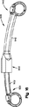
次に、図26〜図27を参照すると、実施形態による装置1300が示されており、ロッド1312を有する第1の部材1310と、管状部材1322を有する第2の部材1320とを有し、さらに、第1の部材1310を第2の部材1320に対して選択的に変位させるために、ロッド1312と関連した駆動組立体1330を具備している。より詳しくは、駆動組立体1330は、磁気アクチュエータ1332を具備し、第1のフリーホイールクラッチ1334を動作させて、好ましくは、軸1336を回転させて、好ましくは、軸1336を中心として、ケーブル1340を巻き取る。図示の実施形態においては、ケーブル1340は、通路1313aの内部に受け入れられ、通路1313aは、ロッド1312の長さに沿って第1の側部1314を走行し、通路1313bは、ロッド1312の長さに沿って第2の側部1315を走行し、ケーブル1340が軸1336を中心として巻き取られるとき、ケーブル1340は、通路1313a内では第1の方向Cに動き、通路1313b内では、第1の方向Cとは異なる、第2の方向Dに動くことが好ましい。
図26〜図28は、実施形態による装置1300を示しており、第1の側部1314は第2の側部1315とは異なっているけれども、第1の側部1314と第2の側部1315とは設計事項としては同一の側部でもよいことを理解されたい。好ましくは、ケーブル1340の第1の端部1342は、管状部材1322に結合され、より好ましくは固定されている。従って、第1のフリーホイールクラッチ1334が回転すると、ケーブル1340は、軸1336を中心として巻き取られ、ケーブル1340における第1の端部1342は方向Dに引っ張られ、従って、管状部材1322は方向Dに変位して、駆動組立体1330から遠ざかり、従って、装置1300を拡張させる。駆動組立体1330は、第2のフリーホイールクラッチ1339を具備し、軸1336に結合され、軸1336の逆回転を防止する。
26-27, an
FIGS. 26-28 illustrate an
1つの実施形態によるアクチュエータは、歯車列を具備している。例えば、回転部材を回転させる磁石を有し、これが駆動部材を回転させるようなアクチュエータにおいて、歯車列は、磁石と回転部材との間に、又は、回転部材と駆動部材との間に、設計事項として、設けられる。歯車列は、駆動組立体など、装置における様々な部分に設けられることを理解されたい。 An actuator according to one embodiment comprises a gear train. For example, in an actuator having a magnet that rotates a rotating member, and this rotates a driving member, the gear train is a design matter between the magnet and the rotating member, or between the rotating member and the driving member. As provided. It should be understood that the gear train is provided in various parts of the apparatus, such as the drive assembly.
1つの好ましい実施形態による装置は、完全に収縮したとき、約10〜200mm、より好ましくは、約20〜180mm、最も好ましくは、約30〜150mmの長さを有する。さらに、1つの実施形態による装置は、完全に拡張したとき、約20〜400mm、より好ましくは、約30〜350mm、最も好ましくは、約40〜300mmの長さを有する。装置の曲率半径は、好ましくは、約100〜300mm、より好ましくは、約150〜250mm、最も好ましくは、約220mmである。しかしながら、装置における好ましい形状、長さ、曲率などは、装置が挿入され、好ましくはインプラントされる体に従って変化することを理解されたい。 The device according to one preferred embodiment has a length of about 10-200 mm, more preferably about 20-180 mm, most preferably about 30-150 mm when fully contracted. Furthermore, the device according to one embodiment has a length of about 20-400 mm, more preferably about 30-350 mm, most preferably about 40-300 mm when fully expanded. The radius of curvature of the device is preferably about 100-300 mm, more preferably about 150-250 mm, and most preferably about 220 mm. However, it should be understood that the preferred shape, length, curvature, etc. in the device will vary depending on the body in which the device is inserted and preferably implanted.
さらに、ある種の実施形態による駆動部材は、雄ねじを有するとして説明したけれども、当業者が認識するように、実施形態による駆動部材は、設計事項として、雌ねじを有し、また、逆もまた同様である。例えば、雌ねじを設けることは、駆動力を増加させる。 Furthermore, although the drive member according to certain embodiments has been described as having a male thread, as those skilled in the art will appreciate, the drive member according to the embodiment has a female thread as a design matter, and vice versa. It is. For example, providing an internal thread increases the driving force.
本発明とその利点について詳細に説明したけれども、様々な変更、置換、変形を行っても、特許請求の範囲に定められた本発明の精神及び範囲から逸脱しないことを理解されたい。さらに、本願の範囲は、明細書に開示された、特定の実施形態の工程、機械、製造、物質の組成、手段、方法、及び段階に制限されることを意図していない。当業者が本発明の開示から容易に認識するように、工程、機械、製造、物質の組成、手段、方法、又は段階であって、本願に開示した実施形態に対応するものとして、現在存在し又は将来開発され、実質的に同一の機能を実行し、又は、実質的に同一の結果を達成するものは、本発明に従って利用できる。 Although the invention and its advantages have been described in detail, it should be understood that various changes, substitutions and modifications do not depart from the spirit and scope of the invention as defined in the claims. Further, the scope of the present application is not intended to be limited to the particular embodiment processes, machines, manufacture, material compositions, means, methods, and steps disclosed in the specification. As those skilled in the art will readily appreciate from the disclosure of the present invention, processes, machines, manufacturing, material compositions, means, methods, or steps currently exist as corresponding to the embodiments disclosed herein. Or those developed in the future that perform substantially the same function or achieve substantially the same result can be utilized in accordance with the present invention.
当業者にあっては、特許請求の範囲の広義の範囲から逸脱せずに、本発明の様々な変形例及び改変例を作れることを認識されたい。これらのいくつかは上述され、他のものは、当業者にとって明らかである。 Those skilled in the art will recognize that various variations and modifications of the invention can be made without departing from the broad scope of the claims. Some of these are described above and others will be apparent to those skilled in the art.
Claims (21)
第1の骨取付部材と、
駆動部材を有する第2の骨取付部材と、
駆動部材と機能的に関連して、変位方向へ駆動部材を前進させるクラッチ機構と、
クラッチ機構に動きを与えるように構成され配置されたアクチュエータとを備え、
クラッチ機構が、
複数のローラと、
ローラと駆動部材とを収容するハウジングであって、収束する内壁部分を有しているような上記ハウジングと、
第1の方向へのハウジングの回転に際して、ローラは、ハウジングと駆動部材との間に楔状になって、駆動部材は第1の方向に回転するような、第1の状態と、
第1の方向とは異なる第2の方向へのハウジングの回転に際して、駆動部材は回転せずに静止して維持される第2の状態と、を備え、
アクチュエータは、外部磁場によって回転可能な、磁石を備えていることを特徴とする装置。A bone displacement device, which is
A first bone attachment member;
A second bone attachment member having a drive member;
A clutch mechanism that is functionally associated with the drive member to advance the drive member in a displacement direction;
An actuator configured and arranged to impart motion to the clutch mechanism;
The clutch mechanism
Multiple rollers,
A housing for housing the roller and the drive member, the housing having a converging inner wall portion;
A first state in which the roller is wedge-shaped between the housing and the drive member upon rotation of the housing in the first direction, and the drive member rotates in the first direction;
A second state in which the drive member remains stationary without rotating when the housing rotates in a second direction different from the first direction ;
The actuator is provided with a magnet that can be rotated by an external magnetic field .
軸は、クラッチ機構に機能的に関連しており、クラッチ機構は第2の取付部材から第1の取付部材を変位させるために、軸を回転させるように構成されていることを特徴とする請求項1に記載の装置。A cable having a first end coupled to the shaft and a second end coupled to the first bone attachment member;
The shaft is functionally associated with the clutch mechanism, the clutch mechanism being configured to rotate the shaft to displace the first mounting member from the second mounting member. Item 2. The apparatus according to Item 1.
クラッチ機構に結合されたレバーであって、開口部を有している上記レバーと、
開口部の内部に配置された偏心円板であって、偏心円板の回転はレバーを変位させ、クラッチ機構に動きを提供するような、上記偏心円板と、
を備えていることを特徴とする請求項1に記載の装置。The device further
A lever coupled to the clutch mechanism, the lever having an opening;
An eccentric disc disposed within the opening, wherein the eccentric disc rotates to displace the lever and provide motion to the clutch mechanism; and
The apparatus of claim 1, comprising:
駆動部材に接触するように構成され配置された、第1のねじ付き側部を有するねじ付き部分と、
駆動部材とは接触しない第2の側部と、
を備えていることを特徴とする請求項1に記載の装置。The first bone attachment member has a portion having a substantially cross-shaped cross section,
A threaded portion having a first threaded side configured and arranged to contact the drive member;
A second side that does not contact the drive member;
The apparatus of claim 1, comprising:
第1の曲率半径を有する第1の取付部材と、
第2の曲率半径を有する第2の取付部材であって、第1のねじ付き部分を具備しているような上記第2の取付部材と、
第2のねじ付き部分と、ねじ無し部分とを有する駆動部材であって、ねじ付き部分は、第2の取付部材における第1のねじ付き部分に接触するように構成され配置され、駆動部材は、第1の取付部材に機能的に結合され、駆動部材の回転が、第2の取付部材に対して第1の取付部材を選択的に変位させるような上記駆動部材と、
を備えていることを特徴とする装置。A device that displaces tissue,
A first attachment member having a first radius of curvature;
A second mounting member having a second radius of curvature, wherein the second mounting member comprises a first threaded portion;
A drive member having a second threaded portion and an unthreaded portion, wherein the threaded portion is configured and arranged to contact the first threaded portion of the second mounting member, the drive member being The drive member functionally coupled to the first attachment member such that rotation of the drive member selectively displaces the first attachment member relative to the second attachment member;
A device characterized by comprising:
Applications Claiming Priority (5)
| Application Number | Priority Date | Filing Date | Title |
|---|---|---|---|
| US79058906P | 2006-04-06 | 2006-04-06 | |
| US60/790,589 | 2006-04-06 | ||
| US86673906P | 2006-11-21 | 2006-11-21 | |
| US60/866,739 | 2006-11-21 | ||
| PCT/US2007/066115 WO2007118179A2 (en) | 2006-04-06 | 2007-04-05 | Remotely adjustable tissue displacement device |
Publications (3)
| Publication Number | Publication Date |
|---|---|
| JP2009532190A JP2009532190A (en) | 2009-09-10 |
| JP2009532190A5 JP2009532190A5 (en) | 2010-05-27 |
| JP5095723B2 true JP5095723B2 (en) | 2012-12-12 |
Family
ID=38921812
Family Applications (1)
| Application Number | Title | Priority Date | Filing Date |
|---|---|---|---|
| JP2009504485A Active JP5095723B2 (en) | 2006-04-06 | 2007-04-05 | Remotely adjustable tissue displacement device |
Country Status (7)
| Country | Link |
|---|---|
| US (1) | US8016837B2 (en) |
| EP (2) | EP2001382B1 (en) |
| JP (1) | JP5095723B2 (en) |
| AU (1) | AU2007234790A1 (en) |
| BR (1) | BRPI0709893A2 (en) |
| CA (1) | CA2648082C (en) |
| WO (1) | WO2007118179A2 (en) |
Cited By (1)
| Publication number | Priority date | Publication date | Assignee | Title |
|---|---|---|---|---|
| JP2011519304A (en) * | 2008-04-30 | 2011-07-07 | モキシメッド インコーポレイテッド | Surgical implantation method and instrument for external joint mechanical energy absorber |
Families Citing this family (107)
| Publication number | Priority date | Publication date | Assignee | Title |
|---|---|---|---|---|
| US7464847B2 (en) | 2005-06-03 | 2008-12-16 | Tyco Healthcare Group Lp | Surgical stapler with timer and feedback display |
| US10285694B2 (en) | 2001-10-20 | 2019-05-14 | Covidien Lp | Surgical stapler with timer and feedback display |
| ES2279231T3 (en) | 2003-05-09 | 2007-08-16 | Tyco Healthcare Group Lp | ANASTOMOTIC STAPLE WITH CAPILLARY TUBE THAT DISPENSES FLUIDS. |
| US7955357B2 (en) | 2004-07-02 | 2011-06-07 | Ellipse Technologies, Inc. | Expandable rod system to treat scoliosis and method of using the same |
| US8114158B2 (en) | 2004-08-03 | 2012-02-14 | Kspine, Inc. | Facet device and method |
| US9717537B2 (en) * | 2004-08-30 | 2017-08-01 | Globus Medical, Inc. | Device and method for treatment of spinal deformity |
| US11291443B2 (en) | 2005-06-03 | 2022-04-05 | Covidien Lp | Surgical stapler with timer and feedback display |
| EP1937157B1 (en) | 2005-06-03 | 2020-08-05 | Covidien LP | Surgical stapler with timer and feedback display |
| AU2007234790A1 (en) * | 2006-04-06 | 2007-10-18 | Synthes Gmbh | Remotely adjustable tissue displacement device |
| WO2007118177A2 (en) | 2006-04-06 | 2007-10-18 | Synthes (U.S.A.) | Remotely adjustable tissue displacement device |
| US8246533B2 (en) | 2006-10-20 | 2012-08-21 | Ellipse Technologies, Inc. | Implant system with resonant-driven actuator |
| US7862502B2 (en) | 2006-10-20 | 2011-01-04 | Ellipse Technologies, Inc. | Method and apparatus for adjusting a gastrointestinal restriction device |
| US8398637B2 (en) * | 2006-11-06 | 2013-03-19 | Douglas Eric Parsell | Device and method for less invasive surgical stabilization of pelvic fractures |
| US7431188B1 (en) | 2007-03-15 | 2008-10-07 | Tyco Healthcare Group Lp | Surgical stapling apparatus with powered articulation |
| US11259802B2 (en) | 2007-04-13 | 2022-03-01 | Covidien Lp | Powered surgical instrument |
| US20080255413A1 (en) | 2007-04-13 | 2008-10-16 | Michael Zemlok | Powered surgical instrument |
| US7950560B2 (en) | 2007-04-13 | 2011-05-31 | Tyco Healthcare Group Lp | Powered surgical instrument |
| US8800837B2 (en) | 2007-04-13 | 2014-08-12 | Covidien Lp | Powered surgical instrument |
| US7823760B2 (en) | 2007-05-01 | 2010-11-02 | Tyco Healthcare Group Lp | Powered surgical stapling device platform |
| US7931660B2 (en) | 2007-05-10 | 2011-04-26 | Tyco Healthcare Group Lp | Powered tacker instrument |
| US7556185B2 (en) | 2007-08-15 | 2009-07-07 | Tyco Healthcare Group Lp | Surgical instrument with flexible drive mechanism |
| US20090112262A1 (en) * | 2007-10-30 | 2009-04-30 | Scott Pool | Skeletal manipulation system |
| US7922063B2 (en) | 2007-10-31 | 2011-04-12 | Tyco Healthcare Group, Lp | Powered surgical instrument |
| US20090248148A1 (en) | 2008-03-25 | 2009-10-01 | Ellipse Technologies, Inc. | Systems and methods for adjusting an annuloplasty ring with an integrated magnetic drive |
| US11202707B2 (en) * | 2008-03-25 | 2021-12-21 | Nuvasive Specialized Orthopedics, Inc. | Adjustable implant system |
| US11241257B2 (en) | 2008-10-13 | 2022-02-08 | Nuvasive Specialized Orthopedics, Inc. | Spinal distraction system |
| US20100094306A1 (en) * | 2008-10-13 | 2010-04-15 | Arvin Chang | Spinal distraction system |
| JP5800428B2 (en) | 2008-11-03 | 2015-10-28 | ジンテス ゲゼルシャフト ミット ベシュレンクテル ハフツング | Adjustable rod assembly |
| US8382756B2 (en) | 2008-11-10 | 2013-02-26 | Ellipse Technologies, Inc. | External adjustment device for distraction device |
| US8828058B2 (en) | 2008-11-11 | 2014-09-09 | Kspine, Inc. | Growth directed vertebral fixation system with distractible connector(s) and apical control |
| US8043338B2 (en) * | 2008-12-03 | 2011-10-25 | Zimmer Spine, Inc. | Adjustable assembly for correcting spinal abnormalities |
| US8197490B2 (en) | 2009-02-23 | 2012-06-12 | Ellipse Technologies, Inc. | Non-invasive adjustable distraction system |
| US8357183B2 (en) | 2009-03-26 | 2013-01-22 | Kspine, Inc. | Semi-constrained anchoring system |
| US9622792B2 (en) | 2009-04-29 | 2017-04-18 | Nuvasive Specialized Orthopedics, Inc. | Interspinous process device and method |
| US8821514B2 (en) | 2009-06-08 | 2014-09-02 | Covidien Lp | Powered tack applier |
| KR101740218B1 (en) | 2009-09-04 | 2017-05-25 | 누베이시브 스페셜라이즈드 오소페딕스, 인크. | Bone growth device and method |
| US9168071B2 (en) | 2009-09-15 | 2015-10-27 | K2M, Inc. | Growth modulation system |
| US8361069B2 (en) | 2009-09-25 | 2013-01-29 | Covidien Lp | Energized needles for wound sealing |
| JP2013512040A (en) * | 2009-11-25 | 2013-04-11 | スパイン21エル・ティー・ディー | Spinal rod with adjustable dimensions after surgery |
| JP6073137B2 (en) * | 2009-12-01 | 2017-02-01 | ジンテス ゲゼルシャフト ミット ベシュレンクテル ハフツング | Non-union scoliosis expandable spinal rod |
| FR2957776B1 (en) * | 2010-03-23 | 2013-02-15 | Arnaud Andre Soubeiran | DEVICE FOR MOVING TISSUES INSIDE THE ORGANISM, ESPECIALLY BONE TISSUES, WITH FIXED TRACTION SCREWS AND ROTATING NUT |
| US8641723B2 (en) | 2010-06-03 | 2014-02-04 | Orthonex LLC | Skeletal adjustment device |
| US9248043B2 (en) | 2010-06-30 | 2016-02-02 | Ellipse Technologies, Inc. | External adjustment device for distraction device |
| US8734488B2 (en) | 2010-08-09 | 2014-05-27 | Ellipse Technologies, Inc. | Maintenance feature in magnetic implant |
| US8282671B2 (en) | 2010-10-25 | 2012-10-09 | Orthonex | Smart device for non-invasive skeletal adjustment |
| US8721566B2 (en) | 2010-11-12 | 2014-05-13 | Robert A. Connor | Spinal motion measurement device |
| US8961567B2 (en) | 2010-11-22 | 2015-02-24 | DePuy Synthes Products, LLC | Non-fusion scoliosis expandable spinal rod |
| WO2012112396A2 (en) | 2011-02-14 | 2012-08-23 | Ellipse Technologies, Inc. | Device and method for treating fractured bones |
| FR2975582B1 (en) * | 2011-05-23 | 2013-06-07 | Ass Marie Lannelongue | OSTEOSYNTHESIS IMPLANT |
| US9333009B2 (en) | 2011-06-03 | 2016-05-10 | K2M, Inc. | Spinal correction system actuators |
| US9381048B2 (en) | 2011-08-31 | 2016-07-05 | DePuy Synthes Products, Inc. | Devices and methods for cervical lateral fixation |
| US10743794B2 (en) | 2011-10-04 | 2020-08-18 | Nuvasive Specialized Orthopedics, Inc. | Devices and methods for non-invasive implant length sensing |
| WO2013066946A1 (en) | 2011-11-01 | 2013-05-10 | Ellipse Technologies, Inc. | Adjustable magnetic devices and methods of using same |
| US9451987B2 (en) | 2011-11-16 | 2016-09-27 | K2M, Inc. | System and method for spinal correction |
| US9468469B2 (en) | 2011-11-16 | 2016-10-18 | K2M, Inc. | Transverse coupler adjuster spinal correction systems and methods |
| US8920472B2 (en) | 2011-11-16 | 2014-12-30 | Kspine, Inc. | Spinal correction and secondary stabilization |
| WO2014172632A2 (en) | 2011-11-16 | 2014-10-23 | Kspine, Inc. | Spinal correction and secondary stabilization |
| WO2013090345A1 (en) * | 2011-12-12 | 2013-06-20 | Austen Bioinnovation Institute In Akron | Noninvasive device for adjusting fastener |
| US10016226B2 (en) | 2011-12-12 | 2018-07-10 | Children's Hospital Medical Center Of Akron | Noninvasive device for adjusting fastener |
| US20130338714A1 (en) | 2012-06-15 | 2013-12-19 | Arvin Chang | Magnetic implants with improved anatomical compatibility |
| EP2908749B1 (en) * | 2012-10-17 | 2019-11-20 | K2M, Inc. | Spinal correction adjustment systems |
| US9044281B2 (en) | 2012-10-18 | 2015-06-02 | Ellipse Technologies, Inc. | Intramedullary implants for replacing lost bone |
| US9084591B2 (en) | 2012-10-23 | 2015-07-21 | Neurostructures, Inc. | Retractor |
| AU2013338218B2 (en) | 2012-10-29 | 2017-05-04 | Nuvasive Specialized Orthopedics, Inc. | Adjustable devices for treating arthritis of the knee |
| US9179938B2 (en) | 2013-03-08 | 2015-11-10 | Ellipse Technologies, Inc. | Distraction devices and method of assembling the same |
| US10226242B2 (en) | 2013-07-31 | 2019-03-12 | Nuvasive Specialized Orthopedics, Inc. | Noninvasively adjustable suture anchors |
| US9801734B1 (en) | 2013-08-09 | 2017-10-31 | Nuvasive, Inc. | Lordotic expandable interbody implant |
| US9468471B2 (en) | 2013-09-17 | 2016-10-18 | K2M, Inc. | Transverse coupler adjuster spinal correction systems and methods |
| US10751094B2 (en) * | 2013-10-10 | 2020-08-25 | Nuvasive Specialized Orthopedics, Inc. | Adjustable spinal implant |
| AU2015253313B9 (en) | 2014-04-28 | 2020-09-10 | Nuvasive Specialized Orthopedics, Inc. | System for informational magnetic feedback in adjustable implants |
| US9931138B2 (en) * | 2014-10-15 | 2018-04-03 | Globus Medical, Inc. | Orthopedic extendable rods |
| KR102559778B1 (en) | 2014-10-23 | 2023-07-26 | 누베이시브 스페셜라이즈드 오소페딕스, 인크. | Remotely adjustable interactive bone reshaping implant |
| WO2016105524A1 (en) | 2014-12-26 | 2016-06-30 | Ellipse Technologies, Inc. | Systems and methods for distraction |
| CA2917676A1 (en) | 2015-01-13 | 2016-07-13 | Stryker European Holdings I, Llc | Growing rods and methods of use |
| WO2016134326A2 (en) | 2015-02-19 | 2016-08-25 | Nuvasive, Inc. | Systems and methods for vertebral adjustment |
| CN113425401A (en) | 2015-10-16 | 2021-09-24 | 诺威适骨科专科公司 | Adjustable device for treating gonitis |
| WO2017100774A1 (en) | 2015-12-10 | 2017-06-15 | Nuvasive Specialized Orthopedics, Inc. | External adjustment device for distraction device |
| ES2805657T3 (en) | 2016-01-28 | 2021-02-15 | Nuvasive Specialized Orthopedics Inc | Systems for bone transport |
| WO2017139548A1 (en) | 2016-02-10 | 2017-08-17 | Nuvasive Specialized Orthopedics, Inc. | Systems and methods for controlling multiple surgical variables |
| WO2017201437A1 (en) | 2016-05-19 | 2017-11-23 | Auctus Surgical, Llc | Spinal curvature modulation systems |
| WO2018102101A2 (en) | 2016-11-09 | 2018-06-07 | Children's Hospital Medical Center Of Akron | Distraction osteogenesis system |
| US10206719B2 (en) | 2016-12-16 | 2019-02-19 | Nuvasive, Inc. | Bone hook apparatus |
| WO2018187797A1 (en) * | 2017-04-07 | 2018-10-11 | K2M, Inc. | Transverse connector |
| US11311295B2 (en) | 2017-05-15 | 2022-04-26 | Covidien Lp | Adaptive powered stapling algorithm with calibration factor |
| US11207066B2 (en) | 2017-10-30 | 2021-12-28 | Covidien Lp | Apparatus for endoscopic procedures |
| US10987104B2 (en) | 2017-10-30 | 2021-04-27 | Covidien Lp | Apparatus for endoscopic procedures |
| US11446064B2 (en) | 2018-04-26 | 2022-09-20 | Stryker European Operations Holdings Llc | Orthopedic growing devices |
| US10835292B2 (en) | 2018-06-13 | 2020-11-17 | Nuvasive, Inc. | Rib fixation device and related methods |
| US11497490B2 (en) | 2018-07-09 | 2022-11-15 | Covidien Lp | Powered surgical devices including predictive motor control |
| US11197734B2 (en) | 2018-10-30 | 2021-12-14 | Covidien Lp | Load sensing devices for use in surgical instruments |
| US11369372B2 (en) | 2018-11-28 | 2022-06-28 | Covidien Lp | Surgical stapler adapter with flexible cable assembly, flexible fingers, and contact clips |
| US11202635B2 (en) | 2019-02-04 | 2021-12-21 | Covidien Lp | Programmable distal tilt position of end effector for powered surgical devices |
| US11376006B2 (en) | 2019-02-06 | 2022-07-05 | Covidien Lp | End effector force measurement with digital drive circuit |
| CN113424555A (en) | 2019-02-07 | 2021-09-21 | 诺威适骨科专科公司 | Ultrasound communication in a medical device |
| US11589901B2 (en) | 2019-02-08 | 2023-02-28 | Nuvasive Specialized Orthopedics, Inc. | External adjustment device |
| US11219461B2 (en) | 2019-03-08 | 2022-01-11 | Covidien Lp | Strain gauge stabilization in a surgical device |
| US11458244B2 (en) | 2020-02-07 | 2022-10-04 | Covidien Lp | Irrigating surgical apparatus with positive pressure fluid |
| US11553913B2 (en) | 2020-02-11 | 2023-01-17 | Covidien Lp | Electrically-determining tissue cut with surgical stapling apparatus |
| US11622768B2 (en) | 2020-07-13 | 2023-04-11 | Covidien Lp | Methods and structure for confirming proper assembly of powered surgical stapling systems |
| US11653919B2 (en) | 2020-11-24 | 2023-05-23 | Covidien Lp | Stapler line reinforcement continuity |
| US11744580B2 (en) | 2020-11-24 | 2023-09-05 | Covidien Lp | Long stapler reloads with continuous cartridge |
| WO2022182582A1 (en) | 2021-02-23 | 2022-09-01 | Nuvasive Specialized Orthopedics, Inc. | Adjustable implant, system and methods |
| US11737787B1 (en) | 2021-05-27 | 2023-08-29 | Nuvasive, Inc. | Bone elongating devices and methods of use |
| US11684362B2 (en) | 2021-06-07 | 2023-06-27 | Covidien Lp | Handheld electromechanical surgical system |
| US11771432B2 (en) | 2021-06-29 | 2023-10-03 | Covidien Lp | Stapling and cutting to default values in the event of strain gauge data integrity loss |
| US11832823B2 (en) | 2022-02-08 | 2023-12-05 | Covidien Lp | Determination of anvil release during anastomosis |
| WO2024028804A1 (en) * | 2022-08-03 | 2024-02-08 | DePuy Synthes Products, Inc. | Rib plating and fixation system |
Family Cites Families (31)
| Publication number | Priority date | Publication date | Assignee | Title |
|---|---|---|---|---|
| CH581988A5 (en) | 1974-04-09 | 1976-11-30 | Messerschmitt Boelkow Blohm | |
| SU865284A1 (en) | 1980-01-11 | 1981-09-23 | Курганский Научно-Исследовательский Институт Экспериментальной И Клинической Ортопедии И Травматологии | Compression-distraction apparatus |
| AT384360B (en) | 1985-09-18 | 1987-11-10 | Kurgansky Niiex I Klinicheskoi | DRIVE FOR COMPRESSION DISTRACTION DEVICES |
| DE3614101C1 (en) * | 1986-04-25 | 1987-10-22 | Juergen Prof Dr Med Harms | Pedicle screw |
| US5092889A (en) | 1989-04-14 | 1992-03-03 | Campbell Robert M Jr | Expandable vertical prosthetic rib |
| US5030235A (en) | 1990-04-20 | 1991-07-09 | Campbell Robert M Jr | Prosthetic first rib |
| US5626579A (en) * | 1993-02-12 | 1997-05-06 | The Cleveland Clinic Foundation | Bone transport and lengthening system |
| AU4179296A (en) | 1994-11-16 | 1996-06-06 | Arnaud Andre Soubeiran | Device for mutually moving two bodies |
| JPH0986474A (en) * | 1995-09-26 | 1997-03-31 | Suzuki Motor Corp | Reverse rotation preventing device for reduction gear train |
| JP3338944B2 (en) * | 1995-08-25 | 2002-10-28 | 有限会社田中医科器械製作所 | Spinal deformity correction device |
| JPH11513598A (en) | 1995-10-20 | 1999-11-24 | ジンテーズ アクチエンゲゼルシャフト クール | Intervertebral implant having a compressible molded hollow member |
| US5704939A (en) * | 1996-04-09 | 1998-01-06 | Justin; Daniel F. | Intramedullary skeletal distractor and method |
| GB9806999D0 (en) | 1998-04-02 | 1998-06-03 | Univ Birmingham | Distraction device |
| US6126664A (en) | 1999-01-19 | 2000-10-03 | Synthes (Usa) | Device and method for locating and resecting bone |
| AU2428401A (en) * | 1999-12-09 | 2001-06-18 | Macropore | Completely resorbable connective tissue distraction devices and techniques |
| FR2805451B1 (en) | 2000-02-29 | 2002-04-19 | Arnaud Andre Soubeiran | IMPROVED DEVICE FOR MOVING TWO BODIES IN RELATION TO ONE ANOTHER, PARTICULARLY FOR REALIZING IMPLANTABLE SYSTEMS IN THE HUMAN BODY |
| FR2819394B1 (en) | 2001-01-17 | 2003-06-13 | Arnaud Andre Soubeiran | ELONGATION ROD |
| FR2822050B1 (en) | 2001-03-13 | 2003-07-25 | Arnaud Andre Soubeiran | DEVICE FOR MOVING IN ONE SENSE ON A DIRECTION DELTA A PORTION OF BONE IN RELATION TO ANOTHER |
| FR2823095B1 (en) * | 2001-04-06 | 2004-02-06 | Ldr Medical | RACHIS OSTEOSYNTHESIS DEVICE AND PLACEMENT METHOD |
| US7135022B2 (en) * | 2001-05-23 | 2006-11-14 | Orthogon 2003 Ltd. | Magnetically-actuable intramedullary device |
| FR2833151B1 (en) * | 2001-12-12 | 2004-09-17 | Ldr Medical | BONE ANCHORING IMPLANT WITH POLYAXIAL HEAD |
| FR2834200A1 (en) | 2001-12-31 | 2003-07-04 | Arnaud Andre Soubeiran | Long bone reconstruction prosthesis has plate attached to existing bone and rod fitting into prosthesis cavity |
| FR2843875B1 (en) | 2002-08-30 | 2004-10-08 | Arnaud Andre Soubeiran | IMPLANTABLE DEVICE FOR TRANSFORMING ON DEMAND ALTERNATE COUPLES APPLIED BY MUSCLE FORCE BETWEEN TWO WORKPIECES IN A MOVEMENT OF TWO BODIES RELATIVELY TO ONE ANOTHER |
| US6723126B1 (en) * | 2002-11-01 | 2004-04-20 | Sdgi Holdings, Inc. | Laterally expandable cage |
| US6918910B2 (en) * | 2002-12-16 | 2005-07-19 | John T. Smith | Implantable distraction device |
| US20050234448A1 (en) | 2004-03-19 | 2005-10-20 | Mccarthy James | Implantable bone-lengthening device |
| US20060228982A1 (en) * | 2005-04-12 | 2006-10-12 | Rehco, Llc | Interactive figure |
| AU2007234790A1 (en) * | 2006-04-06 | 2007-10-18 | Synthes Gmbh | Remotely adjustable tissue displacement device |
| FR2901991B1 (en) | 2006-06-13 | 2021-07-09 | Arnaud Andre Soubeiran | INTRACORPAL EXTENSION DEVICE MOUNTED IN TENSILE SCREW |
| TWI286103B (en) * | 2006-06-28 | 2007-09-01 | Lite On Technology Corp | Print control module of thermal printer |
| FR2906453B1 (en) * | 2006-10-03 | 2009-03-06 | Arnaud Andre Soubeiran | INTRA-BODY LIFTING DEVICE WITH PERMANENT MAGNET. |
-
2007
- 2007-04-05 AU AU2007234790A patent/AU2007234790A1/en not_active Abandoned
- 2007-04-05 CA CA2648082A patent/CA2648082C/en not_active Expired - Fee Related
- 2007-04-05 WO PCT/US2007/066115 patent/WO2007118179A2/en active Application Filing
- 2007-04-05 JP JP2009504485A patent/JP5095723B2/en active Active
- 2007-04-05 EP EP07760231.6A patent/EP2001382B1/en active Active
- 2007-04-05 US US11/697,085 patent/US8016837B2/en active Active
- 2007-04-05 BR BRPI0709893-6A patent/BRPI0709893A2/en not_active Application Discontinuation
- 2007-04-05 EP EP15178469.1A patent/EP2997916B1/en active Active
Cited By (1)
| Publication number | Priority date | Publication date | Assignee | Title |
|---|---|---|---|---|
| JP2011519304A (en) * | 2008-04-30 | 2011-07-07 | モキシメッド インコーポレイテッド | Surgical implantation method and instrument for external joint mechanical energy absorber |
Also Published As
| Publication number | Publication date |
|---|---|
| JP2009532190A (en) | 2009-09-10 |
| CA2648082C (en) | 2014-07-22 |
| WO2007118179A3 (en) | 2008-03-20 |
| CA2648082A1 (en) | 2007-10-18 |
| BRPI0709893A2 (en) | 2011-07-26 |
| EP2001382A2 (en) | 2008-12-17 |
| US20070270803A1 (en) | 2007-11-22 |
| WO2007118179A2 (en) | 2007-10-18 |
| EP2001382B1 (en) | 2015-07-29 |
| EP2997916A1 (en) | 2016-03-23 |
| EP2997916B1 (en) | 2022-08-03 |
| AU2007234790A1 (en) | 2007-10-18 |
| US8016837B2 (en) | 2011-09-13 |
Similar Documents
| Publication | Publication Date | Title |
|---|---|---|
| JP5095723B2 (en) | Remotely adjustable tissue displacement device | |
| JP2009532190A5 (en) | ||
| US10105130B2 (en) | Remotely adjustable tissue displacement device | |
| JP5797654B2 (en) | Osteoporotic bone humeral head fixation device | |
| US9113967B2 (en) | Intracorporeal device for moving tissue | |
| JP2020032234A (en) | Bone growth device and method | |
| RU2438612C2 (en) | Intracorporal elongation device supplied with tensile screws | |
| JP2018532492A5 (en) | ||
| BR102012023921A2 (en) | MESTABLE INSERT IMPLANTS. | |
| CN101466321B (en) | Remotely adjustable tissue displacement device | |
| EP3568097B1 (en) | Spinal screw with movable tip | |
| CN116098689B (en) | Spinal column orthopedic device | |
| JP6818016B2 (en) | Control mechanism for maneuverable rods | |
| JP2023531778A (en) | bone nail device |
Legal Events
| Date | Code | Title | Description |
|---|---|---|---|
| A524 | Written submission of copy of amendment under article 19 pct |
Free format text: JAPANESE INTERMEDIATE CODE: A524 Effective date: 20100405 |
|
| A621 | Written request for application examination |
Free format text: JAPANESE INTERMEDIATE CODE: A621 Effective date: 20100405 |
|
| A977 | Report on retrieval |
Free format text: JAPANESE INTERMEDIATE CODE: A971007 Effective date: 20120427 |
|
| A131 | Notification of reasons for refusal |
Free format text: JAPANESE INTERMEDIATE CODE: A131 Effective date: 20120501 |
|
| A521 | Request for written amendment filed |
Free format text: JAPANESE INTERMEDIATE CODE: A523 Effective date: 20120727 |
|
| TRDD | Decision of grant or rejection written | ||
| A01 | Written decision to grant a patent or to grant a registration (utility model) |
Free format text: JAPANESE INTERMEDIATE CODE: A01 Effective date: 20120820 |
|
| A01 | Written decision to grant a patent or to grant a registration (utility model) |
Free format text: JAPANESE INTERMEDIATE CODE: A01 |
|
| A61 | First payment of annual fees (during grant procedure) |
Free format text: JAPANESE INTERMEDIATE CODE: A61 Effective date: 20120919 |
|
| R150 | Certificate of patent or registration of utility model |
Ref document number: 5095723 Country of ref document: JP Free format text: JAPANESE INTERMEDIATE CODE: R150 Free format text: JAPANESE INTERMEDIATE CODE: R150 |
|
| FPAY | Renewal fee payment (event date is renewal date of database) |
Free format text: PAYMENT UNTIL: 20150928 Year of fee payment: 3 |
|
| R250 | Receipt of annual fees |
Free format text: JAPANESE INTERMEDIATE CODE: R250 |
|
| R250 | Receipt of annual fees |
Free format text: JAPANESE INTERMEDIATE CODE: R250 |
|
| R250 | Receipt of annual fees |
Free format text: JAPANESE INTERMEDIATE CODE: R250 |
|
| R250 | Receipt of annual fees |
Free format text: JAPANESE INTERMEDIATE CODE: R250 |
|
| R250 | Receipt of annual fees |
Free format text: JAPANESE INTERMEDIATE CODE: R250 |
|
| R250 | Receipt of annual fees |
Free format text: JAPANESE INTERMEDIATE CODE: R250 |
|
| R250 | Receipt of annual fees |
Free format text: JAPANESE INTERMEDIATE CODE: R250 |
|
| R250 | Receipt of annual fees |
Free format text: JAPANESE INTERMEDIATE CODE: R250 |
|
| R250 | Receipt of annual fees |
Free format text: JAPANESE INTERMEDIATE CODE: R250 |