JP5084210B2 - Image forming system and control method thereof - Google Patents
Image forming system and control method thereof Download PDFInfo
- Publication number
- JP5084210B2 JP5084210B2 JP2006261414A JP2006261414A JP5084210B2 JP 5084210 B2 JP5084210 B2 JP 5084210B2 JP 2006261414 A JP2006261414 A JP 2006261414A JP 2006261414 A JP2006261414 A JP 2006261414A JP 5084210 B2 JP5084210 B2 JP 5084210B2
- Authority
- JP
- Japan
- Prior art keywords
- image
- image forming
- fixing
- paper
- order
- Prior art date
- Legal status (The legal status is an assumption and is not a legal conclusion. Google has not performed a legal analysis and makes no representation as to the accuracy of the status listed.)
- Expired - Fee Related
Links
Images


Classifications
-
- G—PHYSICS
- G03—PHOTOGRAPHY; CINEMATOGRAPHY; ANALOGOUS TECHNIQUES USING WAVES OTHER THAN OPTICAL WAVES; ELECTROGRAPHY; HOLOGRAPHY
- G03G—ELECTROGRAPHY; ELECTROPHOTOGRAPHY; MAGNETOGRAPHY
- G03G15/00—Apparatus for electrographic processes using a charge pattern
- G03G15/20—Apparatus for electrographic processes using a charge pattern for fixing, e.g. by using heat
- G03G15/2003—Apparatus for electrographic processes using a charge pattern for fixing, e.g. by using heat using heat
- G03G15/2014—Apparatus for electrographic processes using a charge pattern for fixing, e.g. by using heat using heat using contact heat
- G03G15/2064—Apparatus for electrographic processes using a charge pattern for fixing, e.g. by using heat using heat using contact heat combined with pressure
-
- G—PHYSICS
- G03—PHOTOGRAPHY; CINEMATOGRAPHY; ANALOGOUS TECHNIQUES USING WAVES OTHER THAN OPTICAL WAVES; ELECTROGRAPHY; HOLOGRAPHY
- G03G—ELECTROGRAPHY; ELECTROPHOTOGRAPHY; MAGNETOGRAPHY
- G03G15/00—Apparatus for electrographic processes using a charge pattern
- G03G15/65—Apparatus which relate to the handling of copy material
- G03G15/6588—Apparatus which relate to the handling of copy material characterised by the copy material, e.g. postcards, large copies, multi-layered materials, coloured sheet material
- G03G15/6591—Apparatus which relate to the handling of copy material characterised by the copy material, e.g. postcards, large copies, multi-layered materials, coloured sheet material characterised by the recording material, e.g. plastic material, OHP, ceramics, tiles, textiles
-
- G—PHYSICS
- G03—PHOTOGRAPHY; CINEMATOGRAPHY; ANALOGOUS TECHNIQUES USING WAVES OTHER THAN OPTICAL WAVES; ELECTROGRAPHY; HOLOGRAPHY
- G03G—ELECTROGRAPHY; ELECTROPHOTOGRAPHY; MAGNETOGRAPHY
- G03G15/00—Apparatus for electrographic processes using a charge pattern
- G03G15/65—Apparatus which relate to the handling of copy material
- G03G15/6588—Apparatus which relate to the handling of copy material characterised by the copy material, e.g. postcards, large copies, multi-layered materials, coloured sheet material
- G03G15/6594—Apparatus which relate to the handling of copy material characterised by the copy material, e.g. postcards, large copies, multi-layered materials, coloured sheet material characterised by the format or the thickness, e.g. endless forms
-
- G—PHYSICS
- G03—PHOTOGRAPHY; CINEMATOGRAPHY; ANALOGOUS TECHNIQUES USING WAVES OTHER THAN OPTICAL WAVES; ELECTROGRAPHY; HOLOGRAPHY
- G03G—ELECTROGRAPHY; ELECTROPHOTOGRAPHY; MAGNETOGRAPHY
- G03G2215/00—Apparatus for electrophotographic processes
- G03G2215/00362—Apparatus for electrophotographic processes relating to the copy medium handling
- G03G2215/00443—Copy medium
- G03G2215/00451—Paper
- G03G2215/00476—Non-standard property
- G03G2215/00481—Thick
-
- G—PHYSICS
- G03—PHOTOGRAPHY; CINEMATOGRAPHY; ANALOGOUS TECHNIQUES USING WAVES OTHER THAN OPTICAL WAVES; ELECTROGRAPHY; HOLOGRAPHY
- G03G—ELECTROGRAPHY; ELECTROPHOTOGRAPHY; MAGNETOGRAPHY
- G03G2215/00—Apparatus for electrophotographic processes
- G03G2215/00362—Apparatus for electrophotographic processes relating to the copy medium handling
- G03G2215/00443—Copy medium
- G03G2215/00493—Plastic
- G03G2215/00497—Overhead Transparency, i.e. OHP
-
- G—PHYSICS
- G03—PHOTOGRAPHY; CINEMATOGRAPHY; ANALOGOUS TECHNIQUES USING WAVES OTHER THAN OPTICAL WAVES; ELECTROGRAPHY; HOLOGRAPHY
- G03G—ELECTROGRAPHY; ELECTROPHOTOGRAPHY; MAGNETOGRAPHY
- G03G2215/00—Apparatus for electrophotographic processes
- G03G2215/20—Details of the fixing device or porcess
- G03G2215/2003—Structural features of the fixing device
- G03G2215/2006—Plurality of separate fixing areas
Description
本発明は、複数の定着部を有する画像形成装置から構成される画像形成システムおよびその制御方法に関する。 The present invention relates to an image forming system including an image forming apparatus having a plurality of fixing units and a control method therefor.
近年、画像形成システムを構成する電子写真方式を利用したカラー画像形成装置は、画像データを基に変調されたレーザー光線で像担持体上に照射して得られた静電潜像に、イエロー、マゼンタ、シアン、ブラックの4色のトナーを付着させて各トナー像を形成する。そして、このトナー像は、各種の記録媒体(以下、用紙と称す、例えば、PPC用紙、OHPシート、厚紙用紙等)に転写された後、加熱ロール等で溶融固着される。ここで、トナー像を用紙に定着する定着部としては、ロール式定着部やベルト式定着部が採用されている。 2. Description of the Related Art In recent years, color image forming apparatuses using an electrophotographic system constituting an image forming system have been developed to apply yellow, magenta to electrostatic latent images obtained by irradiating an image carrier with a laser beam modulated based on image data. Each toner image is formed by attaching toners of four colors, cyan and black. The toner image is transferred to various recording media (hereinafter referred to as paper, for example, PPC paper, OHP sheet, cardboard paper, etc.) and then melted and fixed by a heating roll or the like. Here, a roll-type fixing unit or a belt-type fixing unit is employed as a fixing unit that fixes a toner image on a sheet.
画像形成装置は、定着後の画像の光沢を高くし、カラー画像の見栄えを良くするために、トナーの粘弾性特性を最適に設計することで定着後の画像の平滑性を向上させる方法が採られる。また、フルカラーの電子写真式プリンタはデジタルカメラの出力用として使用され、高画質、高光沢の画像が求められる。 The image forming apparatus employs a method for improving the smoothness of the image after fixing by optimizing the viscoelastic characteristics of the toner in order to increase the gloss of the image after fixing and improve the appearance of the color image. It is done. Further, full-color electrophotographic printers are used for output of digital cameras, and high-quality and high-gloss images are required.
このような要求から、画像形成装置は、通常の出力に使用する用紙(普通紙)に対して、高い光沢画像を得るための高光沢モードで出力することができる特殊紙が使用されている。この高光沢モードで出力する特殊紙は、用紙の表面に熱可塑性樹脂からなる透明樹脂層が形成されたものである。そこで、透明樹脂層が形成された用紙の表面には、熱可塑性樹脂を含むカラートナーが転写され、加熱、溶融することにより高光沢のカラー画像が形成される。 In view of such a demand, the image forming apparatus uses special paper that can be output in a high gloss mode for obtaining a high gloss image with respect to paper (plain paper) used for normal output. The special paper output in the high gloss mode has a transparent resin layer made of a thermoplastic resin formed on the surface of the paper. Therefore, a color toner containing a thermoplastic resin is transferred to the surface of the paper on which the transparent resin layer is formed, and a high gloss color image is formed by heating and melting.
画像形成装置においては、高い光沢度を出すために、多量の熱量を用紙及びトナーに供給して、用紙やトナーを高温にしトナーを熱で溶融しなければならない。そのための一手段として、定着部を通過する用紙の定着速度を遅くして用紙への定着時間を長くする。しかしながら、用紙の定着速度を遅くして定着時間を長くすると、生産性が低下する。又、この様に定着速度を遅くして定着時間を長くする他の例としては、OHP用紙や厚紙用紙等の特殊紙に画像を形成する場合も同様である。 In an image forming apparatus, in order to obtain a high glossiness, a large amount of heat must be supplied to a sheet and toner, the sheet and toner must be heated to melt the toner. As one means for that purpose, the fixing speed of the sheet passing through the fixing unit is slowed down to increase the fixing time to the sheet. However, when the fixing speed of the paper is decreased and the fixing time is lengthened, the productivity is lowered. As another example of slowing the fixing speed and increasing the fixing time in this way, the same applies to the case of forming an image on special paper such as OHP paper or thick paper.
そこで、画像形成装置は、生産性低下を回避するために、複数の定着部を備えたものがある。例えば、文献1には、定着速度の異なる2つの定着部を有し、高光沢モードでは下流側の低速ベルト定着部にも搬送する構成が記載されている。また、文献2には、2つの定着部を並列に配置し、一方を光沢度制御用とし速度可変とした構成が記載されている。
Accordingly, some image forming apparatuses include a plurality of fixing units in order to avoid a decrease in productivity. For example,
また、1つの定着部を使用する画像形成装置においては、生産性を上げるために時間的なロスを回避する手段としてジョブの順番を変更する手法もある。例えば、文献3には、高光沢モード等に応じて複数の画像形成速度で処理される場合、頁順を変更して高速の頁と低速の頁をまとめて画像形成する構成が記載されている。一方、文献4には、1ジョブ内でカラーとモノクロが混在した画像データの頁順を変更してカラー頁をまとめて画像形成した後、中間トレイに待機させ、次にモノクロ頁をまとめて画像形成し、排紙は頁順に出力する構成が記載されている。
しかし、上記説明した複数の定着部を持つ画像形成装置においては、高光沢の画像を形成するために表面に透明樹脂層を有する用紙やOHP用紙や厚紙用紙などの特殊紙と普通紙とが混載した画像形成モードを指定したジョブの画像形成を出力する場合に、生産性が著しく低下する場合がある。 However, in the above-described image forming apparatus having a plurality of fixing units, special paper such as paper having a transparent resin layer on the surface, OHP paper, cardboard paper, and plain paper are mixed to form a high gloss image. When outputting the image formation of the job with the designated image formation mode, the productivity may be significantly reduced.
すなわち、同一の排紙部に出力物(特殊紙または普通紙上に画像を出力したもの)を積載する場合、出力物の排紙積載順を考慮すると、特殊紙に画像形成する場合に、定着時間又は定着速度を考慮にいれて、後の画像形成開始を遅くする必要がある。 In other words, when stacking output materials (images output on special paper or plain paper) on the same paper discharge unit, considering the output stacking order of output materials, fixing time when forming images on special paper Alternatively, it is necessary to delay the start of subsequent image formation in consideration of the fixing speed.
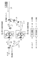
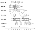
この点について、図1を用いて、詳しく説明する。例えば、図1に示す6枚の画像を順次出力するジョブにおいて、画像1,画像2,画像4,画像6を普通紙で出力し、画像3と画像5を特殊紙で出力する場合を考える。ここで、2つの定着部は普通紙と特殊紙に対応するために異なる定着速度(または定着時間)を有するものであり、特殊紙用の定着部は普通紙用の定着部の定着速度より遅い。このとき、2つの定着部を使用したとしても特殊紙の定着は普通紙の定着より時間がかかる。そのため、6枚の画像を画像1,画像2,画像3,画像4,画像5,画像6の順に出力するには、画像3の次に画像4を出力するために図に示すような画像4の前に待ち(ウエイト)時間が必要になる。画像5も同様であり、画像5の次に画像6が出力されるように画像6の前に待ち(ウエイト)時間が必要になる。
This point will be described in detail with reference to FIG. For example, in a job for sequentially outputting six images shown in FIG. 1, consider a case where
そのため、特殊紙と普通紙を混載したジョブでは、特殊紙が多くなると、待ち時間が多くなり、その結果、画像形成装置の生産性が低下する。 Therefore, in a job in which special paper and plain paper are mixedly loaded, if the number of special paper increases, the waiting time increases, and as a result, the productivity of the image forming apparatus decreases.
本発明は、生産性の低下を回避しながら同一の排紙部に指定された出力物の積載順に排紙することができる画像形成システムおよびその制御方法を提供する。 The present invention provides an image forming system and a control method therefor that can discharge output in the stacking order of output items designated in the same discharge unit while avoiding a decrease in productivity.
上記目的を達成するための本発明に係る画像形成システムは、記録媒体上にトナー画像として画像を形成する画像形成手段と、前記トナー画像を前記記録媒体に定着する第1定着手段と、前記トナー画像を前記記録媒体に定着させる熱量が予め定められた熱量よりも多く必要とする場合に使用される第2定着手段とを有する画像形成システムであって、普通紙及び前記普通紙とは異なる特殊紙とを含む複数の記録媒体に画像を形成する混載モードである場合に、前記第2定着手段を使用して第1記録媒体に定着されるトナー画像が前記第2定着手段を使用せずに第2記録媒体に定着されるトナー像よりも前に形成されるように前記画像形成手段によって形成される画像の順序を変更する制御手段を有し、前記制御手段は、前記画像の順序を変更した場合に、前記第1記録媒体及び前記第2記録媒体が前記画像の順序を変更する前の出力順で排紙されるように前記第1記録媒体及び前記第2記録媒体の搬送を制御することを特徴とする。 In order to achieve the above object, an image forming system according to the present invention includes an image forming unit that forms an image as a toner image on a recording medium, a first fixing unit that fixes the toner image on the recording medium, and the toner. An image forming system having a second fixing unit used when an amount of heat for fixing an image on the recording medium is larger than a predetermined amount of heat, and is different from plain paper and special paper In the mixed loading mode in which images are formed on a plurality of recording media including paper, the toner image fixed on the first recording medium using the second fixing unit does not use the second fixing unit. Control means for changing the order of the images formed by the image forming means so as to be formed before the toner image fixed on the second recording medium; and the control means changes the order of the images. In this case, the conveyance of the first recording medium and the second recording medium is controlled so that the first recording medium and the second recording medium are discharged in the output order before changing the order of the images. It is characterized by that.
本発明の画像形成システムおよびその制御方法によれば、画像を定着させる熱量(温度)が予め定められた熱量(温度)よりも多く(高く)必要とする場合に生じる生産性低下を回避しながら、同一の排紙部にジョブで指定された出力物の積載順に排紙することができる。 According to the image forming system and the control method thereof of the present invention, while avoiding a decrease in productivity that occurs when the amount of heat (temperature) for fixing an image is larger (higher) than a predetermined amount of heat (temperature). Thus, the output can be discharged in the same discharge unit in the order of stacking of output items specified by the job.
<第1の実施形態>
[特徴]
本発明の画像形成システムでは、図1に説明した画像形成を行わせるための画像形成ジョブ(混載)で、特殊画像を定着させる定着器が普通画像を定着させる定着速度よりも遅い場合、即ち、特殊画像を定着させる熱量(温度)が普通画像を定着させる熱量(温度)よりも多く(高く)必要とする場合に、生じる出力の生産性の低下を回避しながら、同一の排紙部に指定された出力物の積載順に排紙することができる。すなわち、本画像形成システムでは、画像形成を行わせるための画像形成ジョブの出力に際して、使用する記録媒体の大きさ、記録媒体上に形成されるトナー画像の種類(普通画像/特殊画像)を判別する。ここで、普通画像とは普通紙に形成する画像で、特殊画像とは特殊紙に形成される画像である。そして、形成される画像が複数(混載:普通画像+特殊画像)と判別された場合には、画像の出力順番を変えないでトナー画像の定着時間を最短にする画像形成順番と画像形成時の待ち時間とを設定することができる。そのため、普通画像より定着時間が長くかかる特殊画像を含むジョブ(混載)において、特殊画像の画像形成順番を普通画像の出力順番より早めるなど画像形成順番を最適化することによって出力の生産性を向上させることができる。
<First Embodiment>
[Feature]
In the image forming system of the present invention, in the image forming job (mixed loading) for causing the image formation described in FIG. 1, when the fixing device for fixing the special image is slower than the fixing speed for fixing the normal image, that is, Designate the same paper output unit while avoiding a decrease in output productivity that occurs when the amount of heat (temperature) for fixing special images is higher (higher) than the amount of heat (temperature) for fixing ordinary images. The output can be discharged in the order of loading. That is, in the present image forming system, when outputting an image forming job for forming an image, the size of the recording medium to be used and the type of toner image formed on the recording medium (normal image / special image) are determined. To do. Here, the normal image is an image formed on plain paper, and the special image is an image formed on special paper. When it is determined that there are a plurality of images to be formed (mixed: normal image + special image), the image formation order and the image formation time for minimizing the fixing time of the toner images without changing the image output order are determined. A waiting time can be set. For this reason, in jobs that include special images that take longer to fix than normal images (mixed loading), the output productivity is improved by optimizing the image formation order, such as making the image formation order of special images faster than the output order of normal images. Can be made.
以下、図面を参照して、本発明の画像形成システムについて詳しく説明する。 Hereinafter, the image forming system of the present invention will be described in detail with reference to the drawings.
[画像形成システム:図2A]
図2Aは、本実施形態の画像形成システムの構成の一部であるカラー画像形成装置の断面図である。
[Image forming system: FIG. 2A]
FIG. 2A is a cross-sectional view of a color image forming apparatus which is a part of the configuration of the image forming system of the present embodiment.
カラー画像形成装置は、画像形成部20、2つの定着器を有する定着部30、中間転写部40、クリーニング部50、給紙部60、および不図示の表示部、入力部、制御部を有する。画像形成部20には、4つの画像形成ステーションPa,Pb,Pc,Pdが並設されており、その構成は同一である。以下、各部の構成について説明する。
The color image forming apparatus includes an
感光ドラム1a〜dは、感光体(第1の画像担持体)であり、矢示の時計方向に所定の周速度(プロセススピード)をもって回転駆動される。感光ドラム1a〜1dは1次帯電器22a〜dにより所定の極性・電位に一様に帯電処理される。
The
次いで、感光ドラム1a〜dには、不図示の像露光手段11a〜dによる画像露光を受けることによりカラー画像の各色成分像(例えば、イエロー色成分像)に対応した静電潜像が形成される。ここで、像露光手段11a〜dは、結像露光光学系、画像情報の時系列電気デジタル画素信号に対応して変調されたレーザービームを出力するレーザースキャナによる走査露光系などから構成される。
Next, an electrostatic latent image corresponding to each color component image (for example, a yellow color component image) of a color image is formed on the
次いで、静電潜像が第1の現像器23aにより第1色である黒トナーKにより現像される。ほぼ同時に、第2〜第4の現像器(イエロー色現像器23b、マゼンタ色現像器23c、シアン色現像器23d)が作動し、各静電潜像が各現像器23b〜dによりイエロー色、マゼンタ色、シアン色に現像される。
Next, the electrostatic latent image is developed with the black toner K as the first color by the first developing
中間転写ベルト40(第2の画像担持体)は時計方向に感光ドラム1a〜dと同じ周速度をもって回転駆動される。感光ドラム1a上に形成され、第1色の黒トナーKにより現像されたトナー画像は、感光ドラム1aと中間転写ベルト40とのニップ部T1を通過する。この過程で、トナー画像は、1次転写ローラ24aから中間転写ベルト40に印加される1次転写バイアスにより、中間転写ベルト40の外周面に順次1次転写されていく。
The intermediate transfer belt 40 (second image carrier) is rotationally driven in the clockwise direction at the same peripheral speed as the
中間転写ベルト40にトナー画像の転写を終えた感光ドラム1aの表面は、クリーニング部12aにより清掃される。
The surface of the
以下、同様に第2色のイエロートナーにより現像されたトナー画像、第3色のマゼンタトナーにより現像されたトナー画像、第4色のシアントナーにより現像されたトナー画像が感光ドラム1b〜dから順次中間転写ベルト40上に重ね合わせて転写される。その結果、カラー画像に対応したカラートナー画像が形成される。転写を終えた中間転写ベルト40の表面はクリーニング部50により清掃される。
Similarly, a toner image developed with yellow toner of the second color, a toner image developed with magenta toner of the third color, and a toner image developed with cyan toner of the fourth color are sequentially applied from the photosensitive drums 1b to 1d. The images are transferred onto the
2次転写ローラ41は2次転写対向ローラ29に対応し平行に軸受させて中間転写ベルト40の下面部に配設してある。
The
感光ドラム1a〜dから中間転写ベルト40への第1〜第4色のトナー画像の順次重畳転写のための1次転写バイアスは、トナーとは逆極性(+)で印加される。その印加電圧は例えば+100V〜2kVの範囲である。
The primary transfer bias for sequentially superimposing and transferring the first to fourth color toner images from the
中間転写ベルト40上に転写された合成カラートナー画像を用紙P(第3の画像担持体)に転写する場合には、まず、2次転写ローラ41が中間転写ベルト40に当接される。続いて、用紙Pは、給紙カセット60から転写材ガイドを通って、中間転写ベルト40と2次転写ローラ41との当接ニップT2に所定のタイミングで給送され、2次転写バイアスが2次転写ローラ41に印加される。用紙Pには2次転写バイアスにより中間転写ベルト40からカラートナー画像が2次転写される。トナー画像の転写を受けた用紙Pは定着部30へ導入され加熱定着される。
When the composite color toner image transferred onto the
[画像形成システムの制御構成:図2B]
次に、上記説明した画像形成システムの制御構成について図2Bを用いて説明する。
[Control Configuration of Image Forming System: FIG. 2B]
Next, the control configuration of the image forming system described above will be described with reference to FIG. 2B.
制御部はCPU12,ROM13,RAM14などから構成されている。制御部は、画像形成部20、給紙部60,中間転写部40,定着部30,クリーニング部50,表示部70、入力部80などの各部を制御する。すなわち、制御部のCPU12はROM13に記憶されている制御プログラムに基づいてRAM14を作業領域に用いて、各部を制御しながら以下に詳しく説明する特殊画像の画像形成順番を普通画像の出力順番より早めるなどの画像形成順番の最適化する処理を行う。画像形成順番の最適化する処理を行うCPU12、ROM13、RAM14は、画像形成装置、または、画像形成システムの構成の一部であるスキャナやホストコンピュータやサーバ等の外部装置側に設けても良い。
The control unit includes a
[ROM/RAMの構成:図2C]
次に、ROM13,RAM14の構成の一例について図2Cを用いて説明する。
[ROM / RAM configuration: FIG. 2C]
Next, an example of the configuration of the
ROM13,RAM14は、システムプログラム110、画像形成制御プログラム111、並び替え待機時間設定ルーチン112、普通紙と特殊紙の定着時間113、出力プロセス情報114、プログラムロード領域115を含む。画像形成情報114は、並び替え後の画像形成の順番、並び替え後の画像形成時間を調整する待ち時間(調整時間)、第1定着器使用フラグ、第2定着器使用フラグ、ジョブを含む。ジョブは、各頁の、画像データ、定着器使用フラグ、待ち時間(0〜3)を含む。
The
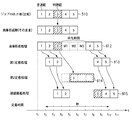
[定着部の構成:図3A]
次に、定着部30の構成の一例について図3Aを用いて説明する。
[Configuration of Fixing Unit: FIG. 3A]
Next, an example of the configuration of the fixing
図3Aの定着部30は、図のように配置された2つの定着器30a、30bを有する。第1定着器30aは、トナー像が転写された普通紙A1の定着に使用され、定着後排紙ローラにより排紙される。この経路は、搬送パスL1→第1定着器30a→第1排紙フラッパ→搬送パスL2→第2排紙フラッパ(排紙側)である。
The fixing
一方、第2定着器30bは、トナー像が転写された特殊紙(透明樹脂層を有する高光沢紙、OHP紙、厚紙)A2の定着に使用され、定着後排紙ローラにより排紙される。この経路は、搬送パスL1→第1定着器30a→第1排紙フラッパ→搬送パスL5→搬送パスL4→第2定着器30b→搬送パスL3→第2排紙フラッパ(排紙側)である。第2定着器30bは第1定着器30aより定着温度を高くする(熱量を多く供給する)ため低速の定着速度で特殊紙を搬送する。第2定着器30bを使用する場合には、特殊紙A2が、第1定着器30aで予備加熱された後、第2定着器30bで定着される。 On the other hand, the second fixing device 30b is used for fixing special paper (high glossy paper having a transparent resin layer, OHP paper, thick paper) A2 on which the toner image is transferred, and is discharged by a discharge roller after fixing. This path is: transport path L1 → first fixing device 30a → first paper discharge flapper → transport path L5 → transport path L4 → second fixing device 30b → transport path L3 → second paper discharge flapper (discharge side). . The second fixing device 30b conveys special paper at a low fixing speed in order to make the fixing temperature higher (supplement of heat) than the first fixing device 30a. When the second fixing device 30b is used, the special paper A2 is preheated by the first fixing device 30a and then fixed by the second fixing device 30b.
図3Aでは、第1、第2定着器30a、30bは同じ構成であり、定着速度を変更することで、それぞれ異なる定着温度(定着温度を高くする場合は定着速度を遅くする)を得ることができる。なお第1と第2定着器の構成が異なる場合は、所望の定着温度が得られるように定着時間を変更する構成とすればよい。 In FIG. 3A, the first and second fixing devices 30a and 30b have the same configuration, and by changing the fixing speed, different fixing temperatures can be obtained (if the fixing temperature is increased, the fixing speed is decreased). it can. If the configurations of the first and second fixing devices are different, the fixing time may be changed so that a desired fixing temperature is obtained.
[定着部の別の構成:図3B]
図3Bは、定着部30の別の構成の一例である。
[Another configuration of fixing unit: FIG. 3B]
FIG. 3B is an example of another configuration of the fixing
図3Bの定着部30は、図のように配置された第1、第2定着器30a、30bを有する。第1定着器30aは、トナー像が転写された普通紙A1の定着に使用され、定着後排紙ローラにより排紙される。この経路は、搬送パスL6→第1排紙フラッパ→搬送パスL7→第1定着器30a→第2排紙フラッパ(排紙側)である。 3B includes first and second fixing devices 30a and 30b arranged as shown. The first fixing device 30a is used for fixing the plain paper A1 to which the toner image is transferred, and is discharged by a discharge roller after fixing. This route is transport path L6 → first discharge flapper → transport path L7 → first fixing device 30a → second discharge flapper (discharge side).
一方、第2定着器30bは、トナー像が転写された特殊紙(透明樹脂層を有する高光沢紙、OHP紙、厚紙)A2の定着に使用され、定着後排紙ローラにより排紙される。第2定着器30bは第1定着器30aより定着温度を高くする(熱量を多く供給する)ため低速の定着速度で特殊紙を搬送する。この経路は、搬送パスL6→第1排紙フラッパ→搬送パスL9、L10→第2定着器30b→搬送パスL11→第2排紙フラッパ(排紙側)である。 On the other hand, the second fixing device 30b is used for fixing special paper (high glossy paper having a transparent resin layer, OHP paper, thick paper) A2 on which the toner image is transferred, and is discharged by a discharge roller after fixing. The second fixing device 30b conveys special paper at a low fixing speed in order to make the fixing temperature higher (supplement of heat) than the first fixing device 30a. This path is transport path L6 → first discharge flapper → transport path L9, L10 → second fixing device 30b → transport path L11 → second discharge flapper (discharge side).
図3Bでは、第1、第2定着器30a、30bは同じ構成であり、定着速度を変更することで、それぞれ異なる定着温度(定着温度を高くする場合は定着速度を遅くする)を得ることができる。なお第1と第2定着器の構成が異なる場合は、所望の定着温度が得られるように定着時間を変更する構成とすればよい。 In FIG. 3B, the first and second fixing devices 30a and 30b have the same configuration, and different fixing temperatures can be obtained by changing the fixing speed (when the fixing temperature is increased, the fixing speed is decreased). it can. If the configurations of the first and second fixing devices are different, the fixing time may be changed so that a desired fixing temperature is obtained.
次に、上記説明した定着部30の搬送経路について説明する。
Next, the conveyance path of the fixing
図3Aの搬送パスL3,L4、L5または図3Bの搬送パスL9,L10,L11は、特殊紙で使用する紙サイズに応じて決められる。例えば、図3Aを例にとって説明すると、図3Aにおいて、搬送パスL4は、普通紙の速度で搬送されてきた記録紙を、第2定着器30bの入口の手前で減速してから第2定着器30bに侵入させる。第2定着器30bの排紙側の搬送パスL3は、普通紙の搬送速度まで加速させる。第2定着器30bの定着速度が第1定着器30aの定着速度と異なる場合は用紙の搬送速度の減速及び加速させる搬送部が必要となる。搬送部は、記録紙の先端と後端速度差による記録紙のループなどを防止する役割を有する。それ故、搬送パスL3〜L5は最大紙サイズ以上の長さを持つことが望ましい。 The conveyance paths L3, L4, L5 in FIG. 3A or the conveyance paths L9, L10, L11 in FIG. 3B are determined according to the paper size used for the special paper. For example, referring to FIG. 3A, in FIG. 3A, the conveyance path L4 decelerates the recording paper conveyed at the normal paper speed before the entrance of the second fixing device 30b and then the second fixing device. Invade 30b. The transport path L3 on the paper discharge side of the second fixing device 30b is accelerated to the transport speed of plain paper. When the fixing speed of the second fixing device 30b is different from the fixing speed of the first fixing device 30a, a transport unit that decelerates and accelerates the paper transport speed is required. The transport unit has a role of preventing a recording paper loop or the like due to a difference in speed between the leading edge and the trailing edge of the recording paper. Therefore, it is desirable that the transport paths L3 to L5 have a length equal to or greater than the maximum paper size.
例えば、A3サイズ(420mm×297mm)の普通紙、特殊紙を定着する場合について図3Aを使って説明する。ここで、普通紙用の第1定着器30aが第1定着速度(300mm/s、紙通過時間1.4秒/A3)で、特殊紙用の第2定着器30bが第2定着速度(50mm/s、紙通過時間8.4秒/A3)とする。この場合、第2定着器30b通過前後の特殊紙は、第1定着速度から第2定着速度まで減速し、その後第2定着速度から第1定着速度に加速する必要がある。そのため、第2定着器30bの前後には、通過する特殊紙のサイズを考慮して、減速用と加速用の搬送パスL5,L4,L3が必要となる。 For example, the case of fixing A3 size (420 mm × 297 mm) plain paper and special paper will be described with reference to FIG. 3A. Here, the first fixing device 30a for plain paper has a first fixing speed (300 mm / s, paper passing time 1.4 seconds / A3), and the second fixing device 30b for special paper has a second fixing speed (50 mm). / s, paper passage time 8.4 seconds / A3). In this case, the special paper before and after passing through the second fixing device 30b needs to be decelerated from the first fixing speed to the second fixing speed and then accelerated from the second fixing speed to the first fixing speed. Therefore, transport paths L5, L4, and L3 for deceleration and acceleration are required before and after the second fixing device 30b in consideration of the size of the special paper that passes therethrough.
[普通紙と特殊紙が混載されたジョブの処理]
次に、上記説明した本画像形成システムにおいて、図3Cに示すような画像形成条件が異なる用紙(普通紙/特殊紙)を用いるジョブ(混載)における画像形成処理について、図4A〜図6Bを用いて具体的に説明する。
[Processing jobs in which plain paper and special paper are mixed]
Next, in the above-described image forming system described above, with reference to FIGS. 4A to 6B, an image forming process in a job (mixed loading) using paper (plain paper / special paper) having different image forming conditions as shown in FIG. 3C will be described. Will be described in detail.
[ジョブ(混載)に一例:図3C]
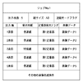
図3Cは、ホストコンピュータやサーバやスキャナなどの外部装置(情報生成手段)から受信したジョブ(混載)の一例である。このジョブは、印刷枚数が5枚で、出力順が1、2,3,4,5頁順で、紙サイズがA3で、普通紙と特殊紙が混載されたものである。そして、1、2,4,5頁目は画像形成条件として第1定着器30aを使用して普通紙に画像を形成し、3頁目は画像形成条件として第2定着器30bを使用して特殊紙に画像を形成するものである。
[Example of job (mixed): Fig. 3C]
FIG. 3C is an example of a job (mixed load) received from an external device (information generation unit) such as a host computer, a server, or a scanner. In this job, the number of printed sheets is 5, the output order is 1, 2, 3, 4 and 5 pages, the paper size is A3, and plain paper and special paper are mixedly loaded. The first, second, fourth, and fifth pages use the first fixing device 30a as an image forming condition to form an image on plain paper, and the third page uses the second fixing device 30b as an image forming condition. An image is formed on special paper.
[ジョブ(混載)の画像形成順番と待ち時間の設定処理:図4A]
本画像形成システムは、図3Cに示すようなジョブを受信すると、展開された画像を一旦RAM14に保持する。そして、図4Aに示すような生産性が高くなるように画像形成順番の並び替え処理を行う。図4Aの処理は、制御部のCPU12がROM13に記憶されている制御プログラムに基づいてRAM14を作業領域に用いて、各部を制御しながら行う処理である。この結果、普通紙及び特殊紙の定着時間がトータルで最短時間となるように画像形成順番が設定され、かつ、定着された普通紙及び特殊紙が正しいページ順になるようにして1つの排紙部に積載されるように、画像形成時の待ち時間が設定される。そのため、本画像形成システムでは、ジョブを高速に出力できるため、全体としての生産性を高めることが可能となる。
[Job (Mixed) Image Formation Order and Wait Time Setting Process: FIG. 4A]
When the image forming system receives a job as shown in FIG. 3C, the developed image is temporarily held in the
まず、図4AのステップS100において、CPU12は、ジョブが普通紙、特殊紙を使用する混載モードか否かを判別する。そして、混載モードと判別された場合には、ステップS200に進み、ジョブから出力に使用する用紙のサイズの判別処理を行う。そして、読み出した用紙サイズから、普通紙と特殊紙の定着器における位置関係を設定する。
First, in step S100 of FIG. 4A, the
即ち、CPU12は、図3Aで第1定着器30aから第2定着器30bを介して排紙されるまでの特殊紙の定着時間B又は枚数Bと、第1定着器30aから排紙されるまでの普通紙の定着時間A又は枚数Aとの関係を予め決められた関係(所定関係)に設定する。そして設定された所定関係から、第2定着器30bで特殊紙を定着しているときに並行して第1定着器30aで定着できる普通紙の枚数が決まる。この所定関係は、紙サイズと搬送路長と速度で決まる。このため、所定関係は、装置固有の値となり、紙サイズと搬送路長と速度から決まる範囲内で任意に設定することができる。なお、本実施形態では、その一例として、紙サイズがA3の場合に、枚数A:枚数B=3未満:1の場合を所定関係と設定する。(紙サイズがA4の場合は、枚数A:枚数B=6未満:2とすればよい。)
ここで、所定関係とは、図3Aでいうと、特殊紙A2が第1定着器30aから第2定着器30bを介して排紙されるまでの時間に、普通紙A1が2枚、第1定着器30aから排紙し終えている関係をいう。このように、所定関係を満たす場合には、第2定着器30bで特殊紙を定着している間に、第1定着器30aで普通紙A1が2枚まで定着することができる。そのため、このように所定関係を満たす場合には、図3Cに示す出力順が3番目の特殊紙の画像形成順番を1番に変更することができる。即ち、定着速度が異なる複数の定着器おいて、遅延時間を考慮して低速の定着速度で画像を形成するモードの頁を先行させている。上記のように、紙サイズがA3の場合は、所定関係が枚数A:枚数B=3未満:1と設定されるため、ジョブの画像の並び替え処理は、3枚以内で行えばよい。
That is, the
Here, in the case of FIG. 3A, the predetermined relationship means that two sheets of plain paper A1 and the first sheet A1 are discharged from the first fixing device 30a through the second fixing device 30b until the first sheet A1 is discharged. A relationship in which the paper is discharged from the fixing device 30a. As described above, when the predetermined relationship is satisfied, up to two plain papers A1 can be fixed by the first fixing device 30a while the special paper is fixed by the second fixing device 30b. Therefore, when the predetermined relationship is satisfied in this way, the image forming order of the third special paper in the output order shown in FIG. 3C can be changed to the first. That is, in a plurality of fixing devices having different fixing speeds, a page of a mode in which an image is formed at a low fixing speed in consideration of the delay time is preceded. As described above, when the paper size is A3, the predetermined relationship is set to the number A: the number B = less than 3: 1. Therefore, the job image rearrangement process may be performed within three sheets.
次に、ステップS300に進み、CPU12は、画像形成順番の並び替えおよび待ち時間決定処理を行う。一方、ステップS100において、CPU12が混載モードでない、すなわち、普通紙または特殊紙のみを使用するモードと判別した場合には、ステップS400に進む。
Next, proceeding to step S300, the
ステップS400では、CPU12は、画像形成処理の指示を与え、次に、ステップS500で定着および排紙処理の指示を与えてから一連の作業を終了する。
In step S400, the
[画像形成順番と待ち時間決定処理:図4B]
次に、図4Bを用いて図4AのステップS300の処理の詳細について説明する。
[Image formation order and waiting time determination processing: FIG. 4B]
Next, details of the processing in step S300 in FIG. 4A will be described with reference to FIG. 4B.
まず、ステップS310において、CPU12は、ジョブの出力に使用する用紙の種別(普通紙/特殊紙)を読み出す。
First, in step S310, the
次に、ステップS320に進む。ステップS320では、CPU12は、ジョブの1頁目の用紙が特殊紙か普通紙かを判定する。そして、1頁目の用紙が特殊紙の場合には、ステップS330に進み、1頁目の画像を特殊紙で出力し、待ち時間を3回(待ち時間Δtは予め決められた時間である)設定してからステップS340に進む。すなわち、図に示すように、画像の入れ替えを行わず、1頁目の画像(1=特殊紙で出力)、待ち時間3回となる。
Next, the process proceeds to step S320. In step S320, the
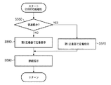
一方、ステップS320において、1頁目の用紙が普通紙の場合には、ステップS350に進み、CPU12は、2頁目の用紙が特殊紙か普通紙かを判定する。そして、2頁目の用紙が特殊紙の場合には、ステップS360に進み、CPU12は、1頁目の画像を2頁目の画像と入れ替えてから、2頁目の画像を特殊紙で出力し、1頁目の画像を普通紙で出力し、待ち時間を2回設定してからステップS340に進む。すなわち、図に示すように、2頁目の画像(2=特殊紙で出力)、1頁目の画像(1=普通紙で出力)、待ち時間2回となる。
On the other hand, if the first page is plain paper in step S320, the process proceeds to step S350, and the
一方、ステップS350において、2頁目の用紙が普通紙の場合には、ステップS370に進み、CPU12は、3頁目の用紙が特殊紙か普通紙かを判定する。そして、3頁目の用紙が特殊紙の場合には、ステップS380に進み、CPU12は、先頭に3頁目の画像を移動し、1頁目と2頁目の画像を1ずつ後に移動して入れ替える。そして、3頁目の画像を特殊紙で出力し、1頁目の画像と2頁目の画像を普通紙で出力し、待ち時間を1回設定してからステップS340に進む。すなわち、図に示すように、3頁目の画像(3=特殊紙で出力)、1頁目、2頁目の画像(1、2=普通紙で出力)、待ち時間1回となる。
On the other hand, if the second page is plain paper in step S350, the process proceeds to step S370, and the
一方、ステップS370において、3頁目の用紙が普通紙の場合には、ステップS390に進み、CPU12は、1頁目の画像、2頁目の画像を普通紙で出力し、待ち時間を0と設定してからステップS340に進む。すなわち、図に示すように、画像の入れ替えを行わず、1頁目、2頁目の画像(1=普通紙で出力)、待ち時間0回となる。
On the other hand, if the third page is plain paper in step S370, the process proceeds to step S390, where the
次に、ステップS340では、CPU12は、全ての用紙の判別を終了したか否かを調べ、終了していない場合には、ステップS395に進み、ジョブから残っている次頁以降の用紙の種別を読み出す。そして、ステップS320に戻り、上記説明した処理を繰り返し行う。尚、この場合、S320、S350、S370における1頁目、2頁目、3頁目は、順次、次頁数と読み替える。
Next, in step S340, the
一方、ステップS340において、全ての用紙の判別を終了した場合には、一連の作業を終了する。 On the other hand, if it is determined in step S340 that all sheets have been identified, the series of operations is terminated.
[定着および排紙処理:図4C]
次に、図4Cを用いて図4AのステップS500の処理の詳細について説明する。図4Cの処理は、図3Aの定着器を使用する場合の処理である。
[Fixing and paper discharge processing: FIG. 4C]
Next, details of the processing in step S500 in FIG. 4A will be described with reference to FIG. 4C. The process of FIG. 4C is a process when the fixing device of FIG. 3A is used.
まず、ステップS510において、CPU12は、第1定着器30aで定着を行うように指示してから、ステップS520に進む。ステップS520では、CPU12は、普通紙か特殊紙か調べ、特殊紙の場合には、ステップS530に進み、第2定着器30bで定着を行うように指示してから、ステップS540に進み、排紙を指示してから一連の作業を終了する。
First, in step S510, the
一方、ステップS520において、CPU12は、普通紙の場合には、ステップS540に進み、排紙を指示してから一連の作業を終了する。
On the other hand, in step S520, in the case of plain paper, the
[定着および排紙処理:図4D]
次に、図4Cを用いて図4AのステップS500の別の処理の詳細について説明する。図4Dの処理は、図3Bの定着器を使用する場合の処理である。
[Fixing and paper discharge processing: FIG. 4D]
Next, details of another process in step S500 of FIG. 4A will be described with reference to FIG. 4C. The process of FIG. 4D is a process when the fixing device of FIG. 3B is used.
まず、ステップS550において、CPU12は、使用する用紙が普通紙か特殊紙か調べ、特殊紙の場合には、ステップS560に進み、第2定着器30bで定着を行うように指示してから、ステップS580に進み、排紙を指示してから一連の作業を終了する。
First, in step S550, the
一方、ステップS550において、CPU12は、使用する用紙が普通紙の場合には、ステップS570に進み、第1定着器30aで定着を行うように指示してから、ステップS580に進み、排紙を指示してから一連の作業を終了する。
On the other hand, in step S550, if the paper to be used is plain paper, the
尚、本実施形態ではジョブの先頭から順に定着時間を判定したが、例えばジョブの長さ分、本例では5枚の出力分について、全体のパターンに基づいてその定着順序や待ち時間を一括して決定してもよい。この場合は、ROMテーブルなどが使用できる。 In this embodiment, the fixing time is determined in order from the beginning of the job. For example, for the length of the job, in this example, for the output of five sheets, the fixing order and the waiting time are collectively based on the entire pattern. May be determined. In this case, a ROM table or the like can be used.
[画像形成順番の並び替え処理の具体例]
次に、上記説明した普通紙と特殊紙を含むジョブ(混載)の画像形成順番の並び替え処理(図4A〜4C)が、図3Aに示す2台の定着器を用いた場合の例を図5A〜図5Eの実施例と図6A、6Bの比較例を用いて説明する。
[Specific example of rearrangement processing of image formation order]
Next, an example in which the image forming order rearrangement process (FIGS. 4A to 4C) of the job (mixed loading) including plain paper and special paper described above uses the two fixing devices shown in FIG. 3A is shown. A description will be given using the example of FIGS. 5A to 5E and the comparative example of FIGS. 6A and 6B.
[実施例1(3頁目に特殊紙がある場合):図5A]
図5Aは、図3Cに示す普通紙と特殊紙を含むジョブ(混載)の画像形成順番の並び替え処理の一例(実施例1)を説明する図である。この場合のジョブは、紙サイズがA3で印刷されるので、所定関係は、枚数A:枚数B=3未満:1と設定されるため、以下に説明するジョブの画像の並び替え処理は、画像3枚以内で行うことになる(図4BのS320、S350,S370)。なお、所定関係が4枚以上であれば、それに応じてジョブの画像の並び替え処理を増加して行うことができる。
[Example 1 (when there is special paper on the third page): FIG. 5A]
FIG. 5A is a diagram illustrating an example (Example 1) of rearrangement processing of the image formation order of a job (mixed) including plain paper and special paper illustrated in FIG. 3C. Since the job in this case is printed with a paper size of A3, the predetermined relationship is set to A: Number B: Number B = less than 3: 1. This is performed within three sheets (S320, S350, and S370 in FIG. 4B). If the predetermined relationship is four or more, the job image rearrangement process can be increased accordingly.
ジョブの出力順510は、図3Cのジョブで指定された用紙の種類と出力順を示しており、3頁目の画像を特殊紙で出力し、1,2、4,5頁目を普通紙で出力する。
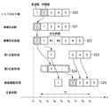
画像形成順511は、出力順510に対して行われた並び替え処理後の画像形成順を示している。すなわち、1〜3頁までの画像の並び替え処理が図4BのステップS310→S320→S350→S370→S380の処理によって行われる。そして、ステップS380にて画像形成順が、ジョブで指定された3頁目の特殊紙で出力する画像を先頭に、1,2頁目の画像を2、3番目になるように並び替えられ、3,2,1の画像形成後に待ち時間1回が設定される。続いて4〜5頁の並び替え処理がステップS340→S395→S320→S350→S370→S390の処理によって行われる。そして、ステップS390にて、画像の並び替え処理が行われる。ただし、この場合には、4,5頁の画像は並び替えられない。この結果、画像形成順511は(3,1,2,4,5)となる。
The
画像形成処理512は、画像形成部における画像形成処理を示しており、並び替えられた画像形成順511に従って5枚の画像の画像形成(トナー画像の形成と転写)のタイミングと待ち時間の関係を示す。すなわち、画像形成部では、3頁目の画像を形成した後に、1,2頁目の画像を連続して形成し、1回の待ち時間(待ち時間Δtは予め決められた時間である)をとってから4,5頁目の画像を連続して形成する。
An image forming process 512 indicates an image forming process in the image forming unit, and the relationship between the timing of image formation (formation and transfer of toner images) of five images and the waiting time in accordance with the rearranged
第1定着処理513、第2定着処理514は、画像形成部で形成された未定着トナー画像を第1定着器30aまたは第2定着器30bで定着されるときのタイミングを示したものである。普通紙は、定着速度の速い第1定着器30aを通過して定着される。一方、特殊紙は、第1定着器30aを通過(予備加熱)したのち定着速度の遅い第2定着器30bを通過して定着される。すなわち、特殊紙を用いる3頁目の画像は第1定着器30aを通過後、第2定着器30bで時間t3〜t6の間で定着される。一方、普通紙を用いる、1頁目の画像が時間t3〜t4の間で、2頁目の画像が時間t4〜t5の間で、4頁目の画像が時間t6〜t7の間で、5頁目の画像が時間t7〜t8の間で、それぞれ第1定着器30aで定着される。
The first fixing process 513 and the
排紙積載処理515は、第1定着器30aまたは第2定着器30bで定着された画像が排紙され積載される順を示している。すなわち、積載される画像の順番はジョブで指定された1,2,3,4,5頁の順である。
The paper
[比較例1(3頁目に特殊紙がある場合):図6A]
一方、図6Aは、図5Aの比較例であり、図3Cのジョブに対して、ジョブの画像形成順の並び替えをしない場合の画像形成、定着、排紙積載のタイミングを示す図である。
[Comparative Example 1 (when there is special paper on the third page): FIG. 6A]
On the other hand, FIG. 6A is a comparative example of FIG. 5A and shows the timing of image formation, fixing, and paper discharge stacking when the job image formation order is not rearranged for the job of FIG. 3C.
図5Aと図6Aの定着時間を比較すると、図5A(実施例1)の定着時間は6t(tは普通紙1枚分の定着時間)、図6A(比較例1)の定着時間は8tであり、実施例1では普通紙2枚分の定着時間が短縮されていることがわかる。これは、図5A(実施例1)では、2つの定着器を同時に使用して(3頁目の画像を第2定着器30bで定着中に1,2頁目の画像を第1定着器30aで定着)しているが、図6A(比較例1)では、2つの定着器が同時に使用できないためである。この結果、本実施例の場合は、普通紙2枚分の定着時間の短縮をすることができた。なお、上記説明したジョブの例は5頁の出力のため短縮効果が少なかったが、頁数が多い場合には、その短縮効果が大きくなるため、出力時間の短縮がより顕著になる。このように、普通画像より定着時間が長くかかる特殊画像を含むジョブ(混載)において、特殊画像の画像形成順番を普通画像の出力順番より早めることによって出力の生産性を向上させることができる。 Comparing the fixing times of FIG. 5A and FIG. 6A, the fixing time of FIG. 5A (Example 1) is 6t (t is the fixing time for one plain paper), and the fixing time of FIG. 6A (Comparative Example 1) is 8t. It can be seen that in Example 1, the fixing time for two sheets of plain paper is shortened. In FIG. 5A (Embodiment 1), two fixing devices are used at the same time (while the image on the third page is being fixed by the second fixing device 30b, the image on the first and second pages is being fixed to the first fixing device 30a. This is because in FIG. 6A (Comparative Example 1), two fixing devices cannot be used at the same time. As a result, in the present embodiment, the fixing time for two sheets of plain paper could be shortened. Note that the above-described job example has a short effect due to the output of five pages. However, when the number of pages is large, the shortening effect becomes large, and the output time is shortened more significantly. In this way, in a job (mixed loading) including a special image that takes a longer fixing time than a normal image, the output productivity can be improved by making the image formation order of the special image faster than the output order of the normal image.
[実施例2(2頁目に特殊紙がある場合):図5B]
図5Bは、ジョブ(混載)の画像形成順番の並び替え処理の別の例(実施例2)を説明する図である。
[Example 2 (when special paper is present on the second page): FIG. 5B]
FIG. 5B is a diagram for explaining another example (Example 2) of the rearrangement process of the image formation order of a job (mixed).
ジョブの出力順520は、ジョブで指定された用紙の種類と出力順を示しており、2頁目の画像を特殊紙で出力し、1,3、4,5頁目を普通紙で出力する。
The
画像形成順521は、出力順520に対して行われた並び替え処理後の画像形成順を示している。すなわち、1〜2頁までの画像の並び替え処理が図4BのステップS310→320→S350→S360の処理によって行われる。そして、ステップS360にて画像形成順が、ジョブで指定された2頁目の特殊紙で出力する画像を先頭に、1頁目の画像を2番目になるように並び替えられ、2,1頁目の画像形成後に待ち時間2回が設定される。続いて3〜5頁の並び替え処理がステップS340→S395→S320→S350→S370→S390の処理によって行われる。そして、ステップS390にて、画像の並び替え処理が行われる。ただし、この場合には、3,4,5頁の画像は並び替えられない。この結果、画像形成順521は(2,1,3,4,5)となる。
The
画像形成処理522は、画像形成部における画像形成処理を示しており、並び替えられた画像形成順521に従って5枚の画像の画像形成(トナー画像の形成と転写)のタイミングと待ち時間の関係を示す。すなわち、画像形成部では、2頁目の画像を形成した後に、1頁目の画像を形成し、2回の待ち時間(待ち時間Δtは予め決められた時間である)をとってから3,4,5頁目の画像を連続して形成する。
An
第1定着処理523、第2定着処理524は、画像形成部で形成された未定着トナー画像を第1定着器30aまたは第2定着器30bで定着されるときのタイミングを示したものである。普通紙は、定着速度の速い第1定着器30aを通過して定着される。一方、特殊紙は、第1定着器30aを通過(予備加熱)したのち定着速度の遅い第2定着器30bを通過して定着される。すなわち、特殊紙を用いる2頁目の画像は第1定着器30aを通過後、第2定着器30bで時間t3〜t6の間で定着される。一方、普通紙を用いる、1頁目の画像が時間t3〜t4の間で、3頁目の画像が時間t6〜t7の間で、4頁目の画像が時間t7〜t8の間で、5頁目の画像が時間t8〜t9の間で、それぞれ第1定着器30aで定着される。
排紙積載処理525は、第1定着器30aまたは第2定着器30bで定着された画像が排紙され積載される順を示している。すなわち、積載される画像の順番はジョブで指定された1,2,3,4,5頁の順である。
The
The paper
なお、図は省略するが、出力順520の画像形成順の並び替えを行なって画像形成した場合は、画像形成順の並び替えをしない場合に比較して普通紙1枚分の定着時間が短縮される。これは、図5B(実施例1)では、2つの定着器を同時に使用(2頁目の画像を第2定着器30bで定着中に1頁目の画像を第1定着器30aで定着)しているためである。この結果、本実施例の場合は、普通紙1枚分の定着時間の短縮をすることができた。このように、普通画像より定着時間が長くかかる特殊画像を含むジョブ(混載)において、特殊画像の画像形成順番を普通画像の出力順番より早めることによって出力の生産性を向上させることができる。
Although not shown in the drawings, when the images are formed by rearranging the image formation order in the
[実施例3(先頭に特殊紙がある場合):図5C]
図5Cは、ジョブ(混載)の画像形成順番の並び替え処理の別の例(実施例3)を説明する図である。
[Example 3 (when special paper is at the top): FIG. 5C]
FIG. 5C is a diagram for explaining another example (Example 3) of the rearrangement process of the image formation order of a job (mixed).
ジョブの出力順530は、ジョブで指定された用紙の種類と出力順を示しており、1頁目の画像を特殊紙で出力し、2,3、4,5頁目を普通紙で出力する。
The
画像形成順531は、出力順530に対して行われた並び替え処理後の画像形成順を示している。すなわち、1頁目の画像の並び替え処理が図4BのステップS310→320→S330の処理によって行われる。そして、ステップS330にて画像形成順は、ジョブで指定された1頁目の特殊紙で出力する画像をそのまま先頭(並び替えない)に配置し、1頁目の画像形成後に待ち時間3回が設定される。続いて2〜5頁の並び替え処理がステップS340→S395→S320→S350→S370→S390の処理によって行われる。そして、ステップS390にて、画像の並び替え処理が行われる。ただし、この場合には、2〜5頁の画像は並び替えられない。この結果、画像形成順531は(1,2,3,4,5)となる。
The
画像形成処理532は、画像形成部における画像形成処理を示しており、並び替えられた画像形成順531に従って5枚の画像の画像形成(トナー画像の形成と転写)のタイミングと待ち時間の関係を示す。すなわち、画像形成部では、1頁目の画像を形成した後に、3回の待ち時間(待ち時間Δtは予め決められた時間である)をとってから2,3,4,5頁目の画像を連続して形成する。
The image forming process 532 shows the image forming process in the image forming unit, and the relationship between the timing of image formation (formation and transfer of toner images) of five images and the waiting time in accordance with the rearranged
第1定着処理533、第2定着処理534は、画像形成部で形成された未定着トナー画像を第1定着器30aまたは第2定着器30bで定着されるときのタイミングを示したものである。普通紙は、定着速度の速い第1定着器30aを通過して定着される。一方、特殊紙は、第1定着器30aを通過(予備加熱)したのち定着速度の遅い第2定着器30bを通過して定着される。すなわち、特殊紙を用いる1頁目の画像は第1定着器30aを通過後、第2定着器30bで時間t3〜t6の間で定着される。一方、普通紙を用いる、2頁目の画像が時間t6〜t7の間で、3頁目の画像が時間t7〜t8の間で、4頁目の画像が時間t8〜t9の間で、5頁目の画像が時間t9〜t10の間で、それぞれ第1定着器30aで定着される。
The
排紙積載処理535は、第1定着器30aまたは第2定着器30bで定着された画像が排紙され積載される順を示している。すなわち、積載される画像の順番はジョブで指定された1,2,3,4,5頁の順である。
The paper
このように、先頭に特殊紙がある場合には、画像形成のために並び替えの必要がないので、定着時間は短縮されない。 As described above, when there is a special paper at the head, it is not necessary to rearrange the images for image formation, so that the fixing time is not shortened.
[実施例4(3、5頁目に特殊紙がある場合):図5D]
図5Dは、ジョブ(混載)の画像形成順番の並び替え処理の別の例(実施例4)を説明する図である。
[Example 4 (when special paper is present on
FIG. 5D is a diagram for explaining another example (Example 4) of the rearrangement processing of the image formation order of a job (mixed loading).
ジョブの出力順540は、ジョブで指定された用紙の種類と出力順を示しており、3、5頁目の画像を特殊紙で出力し、1,2、4頁目を普通紙で出力する。
The
画像形成順541は、出力順540に対して行われた並び替え処理後の画像形成順を示している。すなわち、1〜3頁までの画像の並び替え処理が図4BのステップS310→320→S350→S370→S380の処理によって行われる。そして、ステップS380にて画像形成順が、ジョブで指定された3頁目の特殊紙で出力する画像を先頭に、1、2頁目の画像が2、3番目になるように並び替えられ、3、1、2頁の画像形成後に待ち時間1回が設定される。続いて4〜5頁の並び替え処理がステップS340→S395→S320→S350→S360の処理によって行われる。そして、ステップS360にて、画像の並び替え処理が行われる。すなわち、画像形成順が、ジョブで指定された5頁目の特殊紙で出力する画像を4頁目の画像の前となるように並び替えられる。この結果、画像形成順541は(3,1,2,5,4)となる。
The
画像形成処理542は、画像形成部における画像形成処理を示しており、並び替えられた画像形成順541に従って5枚の画像の画像形成(トナー画像の形成と転写)のタイミングと待ち時間の関係を示す。すなわち、画像形成部では、3頁目の画像を形成した後に1、2頁目の画像を続いて形成し、1回の待ち時間(待ち時間Δtは予め決められた時間である)をとってから5、4頁目の画像を連続して形成する。
The
第1定着処理543、第2定着処理544は、画像形成部で形成された未定着トナー画像を第1定着器30aまたは第2定着器30bで定着されるときのタイミングを示したものである。普通紙は、定着速度の速い第1定着器30aを通過して定着される。一方、特殊紙は、第1定着器30aを通過(予備加熱)したのち定着速度の遅い第2定着器30bを通過して定着される。すなわち、特殊紙を用いる3、5頁目の画像は第1定着器30aを通過後、第2定着器30bで時間t3〜t6、t7〜10の間で定着される。一方、普通紙を用いる、1頁目の画像が時間t3〜t4の間で、2頁目の画像が時間t4〜t5の間で、4頁目の画像が時間t7〜t8の間で、それぞれ第1定着器30aで定着される。
The
排紙積載処理545は、第1定着器30aまたは第2定着器30bで定着された画像が排紙され積載される順を示している。すなわち、積載される画像の順番はジョブで指定された1,2,3,4,5頁の順である。
The paper
[比較例2(3、5頁目に特殊紙がある場合):図6B]
一方、図6Bは、図5Dの比較例であり、ジョブの画像形成順の並び替えをしないで画像形成した場合の画像形成、定着、排紙積載のタイミングを示す図である。図5D(実施例4)と図6B(比較例2)の定着時間を比較すると、図5D(実施例4)の定着時間は8t(tは普通紙1枚分の定着時間)、図6B(比較例2)の定着時間は11tであり、実施例1では普通紙3枚分の定着時間が短縮されていることがわかる。これは、図5Dでは、2つの定着器を同時に使用して(3頁目の画像を第2定着器30bで定着中に1,2頁目の画像を第1定着器30aで定着、5頁目の画像を第2定着器30bで定着中に4頁目の画像を第1定着器30aで定着)している。一方、図6Aでは、2つの定着器が同時に使用できないためである。この結果、本実施例の場合は、普通紙3枚分の定着時間の短縮をすることができた。
[Comparative Example 2 (when special paper is on
On the other hand, FIG. 6B is a comparative example of FIG. 5D and shows the timing of image formation, fixing, and discharge stacking when images are formed without rearranging the job image formation order. Comparing the fixing times of FIG. 5D (Example 4) and FIG. 6B (Comparative Example 2), the fixing time of FIG. 5D (Example 4) is 8t (t is the fixing time for one plain paper), and FIG. The fixing time of Comparative Example 2) is 11 t, and it can be seen that in Example 1, the fixing time for three sheets of plain paper is shortened. In FIG. 5D, two fixing devices are used at the same time (the image of the third page is fixed by the first fixing device 30a while the image of the third page is fixed by the second fixing device 30b, and the
[実施例5(2、5頁目に特殊紙がある場合):図5E]
図5Eは、ジョブ(混載)の画像形成順番の並び替え処理の別の例(実施例5)を説明する図である。
[Example 5 (when special paper is present on
FIG. 5E is a diagram for explaining another example (Example 5) of the rearrangement process of the image formation order of a job (mixed).
ジョブの出力順550は、ジョブで指定された用紙の種類と出力順を示しており、2、5頁目の画像を特殊紙で出力し、1,3、4頁目を普通紙で出力する。
The
画像形成順551は、出力順550に対して行われた並び替え処理後の画像形成順を示している。すなわち、1〜2頁までの画像の並び替え処理が図4BのステップS310→320→S350→S360の処理によって行われる。そして、ステップS360にて画像形成順が、ジョブで指定された2頁目の特殊紙で出力する画像を先頭に、1頁目の画像が2番目になるように並び替えられ、2,1頁目の画像形成後に待ち時間2回が設定される。続いて3〜5頁の並び替え処理がステップS340→S395→S320→S350→S370→S380の処理によって行われる。そして、ステップS380にて、画像の並び替え処理が行われる。すなわち、画像形成順が、ジョブで指定された5頁目の特殊紙で出力する画像を3,4頁目の画像の前となるように並び替えられる。この結果、画像形成順551は(2,1,5,3,4)となる。
The
画像形成処理552は、画像形成部における画像形成処理を示しており、並び替えられた画像形成順551に従って5枚の画像の画像形成(トナー画像の形成と転写)のタイミングと待ち時間の関係を示す。すなわち、画像形成部では、2頁目の画像を形成した後に1頁目の画像を形成し、2回の待ち時間(待ち時間Δtは予め決められた時間である)をとってから5,3,4頁目の画像を連続して形成する。
The
第1定着処理553、第2定着処理554は、画像形成部で形成された未定着トナー画像を第1定着器30aまたは第2定着器30bで定着されるときのタイミングを示したものである。普通紙は、定着速度の速い第1定着器30aを通過して定着される。一方、特殊紙は、第1定着器30aを通過(予備加熱)したのち定着速度の遅い第2定着器30bを通過して定着される。すなわち、特殊紙を用いる2、5頁目の画像は第1定着器30aを通過後、第2定着器30bで時間t3〜t6、t7〜10の間で定着される。一方、普通紙を用いる、1頁目の画像が時間t3〜t4の間で、3頁目の画像が時間t7〜t8の間で、4頁目の画像が時間t8〜t9の間で、それぞれ第1定着器30aで定着される。
The
排紙積載処理555は、第1定着器30aまたは第2定着器30bで定着された画像が排紙され積載される順を示している。すなわち、積載される画像の順番はジョブで指定された1,2,3,4,5頁の順である。
The paper
なお、図は省略するが、ジョブ550の画像形成順の並び替えを行なって画像形成した場合は、画像形成順の並び替えをしない場合に比較して普通紙3枚分の定着時間が短縮される。これは、図5E(実施例4)では、2台の定着器を同時に使用(2頁目の画像を第2定着器30bで定着中に1頁目の画像を第1定着器30aで定着、5頁目の画像を第2定着器30bで定着中に3,4頁目の画像を第1定着器30aで定着)しているためである。この結果、本実施例の場合は、普通紙3枚分の定着時間の短縮をすることができた。
Although illustration is omitted, when images are formed by rearranging the image formation order of the
このように、普通画像より定着時間が長くかかる特殊画像を含むジョブ(混載)において、特殊画像の画像形成順番を普通画像の出力順番より早めることによって出力の生産性を向上させることができる。 In this way, in a job (mixed loading) including a special image that takes a longer fixing time than a normal image, the output productivity can be improved by making the image formation order of the special image faster than the output order of the normal image.
[図3Bの構成の定着器を使用する場合]
上記説明した実施例は、図3Aに示す2つの定着器を用いた場合であった。
[When using a fixing device having the configuration shown in FIG. 3B]
In the embodiment described above, the two fixing devices shown in FIG. 3A were used.
しかしながら、図3Bに示す構成の2つの定着器を並列に接続して別々に使用する場合には、図3Aに示す構成の2台の定着器を用いる場合よりも更に画像形成の順番の自由度が増加することを説明する。 However, when two fixing devices having the configuration shown in FIG. 3B are connected in parallel and used separately, the degree of freedom in the order of image formation is further increased than when two fixing devices having the configuration shown in FIG. 3A are used. Explain that increases.
図3Bに示す構成では、第1定着器30aは、トナー像が転写された普通紙A1の定着のみに使用され、第2定着器30bは、トナー像が転写された特殊紙A2の定着のみに使用される。ここで、普通紙用の第1定着器30aが第1定着速度(300mm/s、紙通過時間1.4秒/A3)で、特殊紙用の第2定着器30bが第2定着速度(50mm/s、紙通過時間8.4秒/A3)とする。 In the configuration shown in FIG. 3B, the first fixing device 30a is used only for fixing the plain paper A1 to which the toner image is transferred, and the second fixing device 30b is used only for fixing the special paper A2 to which the toner image is transferred. used. Here, the first fixing device 30a for plain paper has a first fixing speed (300 mm / s, paper passing time 1.4 seconds / A3), and the second fixing device 30b for special paper has a second fixing speed (50 mm). / s, paper passage time 8.4 seconds / A3).
この場合、第1定着器30aと第2定着器30bとが用紙の種別に対応して単独に使用され、第2定着器30b側には2つ以上の搬送パスL9,L10,L11が必要であるので、第1定着器30a側は第2定着器30b側に比べて搬送路が短くなる。そのため、図3Aの構成に比べて、図3Bの構成では、第2定着器30b側で定着されている場合に、第1定着部30a側で定着され排紙部に排紙される枚数が、多くなる。このため、図3Bの構成は、図3Aの構成に比べて、特殊紙を定着する場合のウエイト時間を減らすことが可能となる。その結果、普通画像より定着時間が長くかかる特殊画像を含むジョブ(混載)において、特殊画像の画像形成順番を普通画像の出力順番より早めることによって出力の生産性をさらに向上させることができる。 In this case, the first fixing device 30a and the second fixing device 30b are used independently corresponding to the type of paper, and two or more transport paths L9, L10, L11 are required on the second fixing device 30b side. Therefore, the conveyance path on the first fixing device 30a side is shorter than that on the second fixing device 30b side. Therefore, compared with the configuration of FIG. 3A, in the configuration of FIG. 3B, when the image is fixed on the second fixing device 30b side, the number of sheets fixed on the first fixing unit 30a side and discharged to the paper discharge unit is Become more. For this reason, the configuration of FIG. 3B can reduce the wait time when fixing special paper as compared to the configuration of FIG. 3A. As a result, in a job (mixed loading) including a special image that takes a longer fixing time than a normal image, the output productivity can be further improved by making the image formation order of the special image faster than the output order of the normal image.
なお、以上の説明では、紙サイズをA3サイズ、本体の搬送部の長さをA3の長さに限定して説明した。しかしながら、紙サイズ、搬送部の長さは自由に変更することができる。またこの場合に、画像形成順番の上限もそれに応じて決めることができる。 In the above description, the paper size is limited to A3 size, and the length of the conveyance unit of the main body is limited to A3 length. However, the paper size and the length of the transport unit can be freely changed. In this case, the upper limit of the image formation order can be determined accordingly.
<第2の実施形態>
以下、第2の実施形態について説明する。なお、第2の実施形態の画像形成装置は第1の実施形態の画像形成装置と類似するものである。そこで、第2の実施形態の画像形成装置についての説明は、第1の実施形態の画像形成装置と異なる部分についてのみ説明し、共通する部分の説明は重複するので省略する。
<Second Embodiment>
Hereinafter, the second embodiment will be described. Note that the image forming apparatus of the second embodiment is similar to the image forming apparatus of the first embodiment. Therefore, in the description of the image forming apparatus of the second embodiment, only the parts different from the image forming apparatus of the first embodiment will be described, and the description of the common parts will be omitted because they are duplicated.
[特徴]
第1の実施形態では、普通紙と特殊紙(高光沢モード)を含むジョブ(混載)において、特殊紙を用いる特殊画像の画像形成順番を普通画像の出力順番より早めるなど、画像形成順番を最適化することによって出力の生産性を向上させることを説明した。本実施形態では、トナー載り量、あるいは、トナー種が異なるグロスモードに適用する例について説明する。グロスモードとは透明トナーを用いて紙の特性とは関係なく最終画像のグロスをコントロールするものである。グロスモードでは、紙の表面条件にもよるが、透明トナーを白地部(印刷されていない部分)に載せて画像部と非画像部の段差を無くすようにする処理である。なお、グロスモードでは場合によっては色トナーを被覆するように画像形成してもよい。そして、通常の画像形成モードの(前述の普通画像に相当する)場合は、第1定着器30aを使用して定着し、グロスモードの(前述の特殊画像に相当する)場合は第1定着器30aと低速の第2定着器30bを使用して高温で定着する。そこで、本実施形態でも、第1の実施形態と同様の処理を行うことで出力の生産性を向上させることができる。すなわち、通常の画像形成モードより定着時間が長くかかる(定着する温度が高温または熱量を多く供給する)グロスモードを含むジョブ(混載)において、グロスモードの画像形成順番を通常の画像形成モードの出力順番より早めるなど、画像形成順番を最適化することによって出力の生産性を向上させることができる。
[Feature]
In the first embodiment, in a job (mixed loading) including plain paper and special paper (high gloss mode), the image formation order is optimized such that the image formation order of special images using special paper is made earlier than the output order of normal images. It explained that the productivity of output is improved by making it. In the present embodiment, an example in which the present invention is applied to a gloss mode in which the toner loading amount or the toner type is different will be described. In the gloss mode, transparent toner is used to control the gloss of the final image regardless of the characteristics of the paper. In the gloss mode, although it depends on the surface condition of the paper, the transparent toner is placed on the white background portion (the portion not printed) to eliminate the step between the image portion and the non-image portion. In the gloss mode, an image may be formed so as to cover the color toner in some cases. In the normal image forming mode (corresponding to the above-described normal image), the first fixing device 30a is used for fixing. In the gloss mode (corresponding to the above-described special image), the first fixing device is used. Fixing is performed at a high temperature using the low-speed second fixing device 30b. Therefore, in this embodiment as well, output productivity can be improved by performing the same processing as in the first embodiment. That is, in a job (mixed loading) including a gloss mode that takes a longer fixing time than the normal image formation mode (the fixing temperature is high or supplies a large amount of heat), the image formation order of the gloss mode is output in the normal image formation mode. It is possible to improve output productivity by optimizing the image formation order such as earlier than the order.
[画像形成装置:図7]
図7は、本実施形態の画像形成システムの一例を示すカラー画像形成装置の断面図である。本実施形態の画像形成装置が第1の実施形態の画像形成装置と異なる点は、透明トナー画像形成ステ―ションP0が一つ追加された構成となっている点である。
[Image forming apparatus: FIG. 7]
FIG. 7 is a cross-sectional view of a color image forming apparatus showing an example of the image forming system of this embodiment. The image forming apparatus of the present embodiment is different from the image forming apparatus of the first embodiment in that one transparent toner image forming station P0 is added.
透明トナーは紙の特性とは関係なく、最終画像のグロスをコントロールするものである。この透明トナーは必ずしも、他のステーションの色トナーと同じ粘弾特性をもつ必要はない。本画像形成装置では、透明トナーを用いて最終画像グロスコントロールを行うことができる。すなわち、グロスモードの場合には、透明トナーを白地部(画像形成されていない部分)に載せて画像部と非画像部の段差を無くすようにする。そして、グロスモードの場合は低速の第2定着器を使用して高温で定着する。この結果、画像部と非画像部の段差がない最終画像を得ることができる。 The transparent toner controls the gloss of the final image regardless of the characteristics of the paper. This transparent toner is not necessarily required to have the same viscoelastic properties as the color toner of other stations. In this image forming apparatus, the final image gloss control can be performed using the transparent toner. That is, in the case of the gloss mode, the transparent toner is placed on the white background portion (the portion where no image is formed) to eliminate the step between the image portion and the non-image portion. In the case of the gloss mode, fixing is performed at a high temperature using a low-speed second fixing device. As a result, a final image having no step between the image portion and the non-image portion can be obtained.
一方、通常の画像形成モードの場合には、透明トナーを使用しないため、通常の画像形成速度の第1定着器を使用して定着する。 On the other hand, in the normal image forming mode, since the transparent toner is not used, fixing is performed using the first fixing device having a normal image forming speed.
尚、前述の普通紙と特殊紙の混載モード、通常の画像形成モード、グロスモード等の画像形成モードは入力部80から設定、または、外部装置から受信した画像形成情報に設定されている。
Note that the image forming modes such as the mixed mode of plain paper and special paper, the normal image forming mode, and the gloss mode are set from the
[他の実施形態]
また、本発明の目的は、実施形態の機能を実現するソフトウェアのプログラムコードを記録した記憶媒体を、システム或いは装置に供給してもよい。その場合、そのシステム或いは装置のコンピュータ(またはCPUやMPU等)が記憶媒体に格納されたプログラムコードを読み出して実行することによっても達成される。
[Other Embodiments]
In addition, an object of the present invention may be to supply a system or apparatus with a storage medium that records a program code of software that implements the functions of the embodiments. In that case, it is also achieved by the computer (or CPU, MPU, etc.) of the system or apparatus reading and executing the program code stored in the storage medium.
この場合、記憶媒体から読み出されたプログラムコード自体が前述した実施の形態の機能を実現することになり、そのプログラムコード及び該プログラムコードを記憶した記憶媒体は本発明を構成することになる。 In this case, the program code itself read from the storage medium realizes the functions of the above-described embodiments, and the program code and the storage medium storing the program code constitute the present invention.
また、プログラムコードを供給するための記憶媒体としては、例えば、フロッピー(登録商標)ディスク、ハードディスク、光磁気ディスク、CD−ROM、CD−R、CD−RWを用いることができる。また、DVD−ROM、DVD−RAM、DVD−RW、DVD+RW、磁気テープ、不揮発性のメモリカード、ROM等を用いることができる。または、プログラムコードをネットワークを介してダウンロードしてもよい。 As a storage medium for supplying the program code, for example, a floppy (registered trademark) disk, a hard disk, a magneto-optical disk, a CD-ROM, a CD-R, and a CD-RW can be used. Further, a DVD-ROM, a DVD-RAM, a DVD-RW, a DVD + RW, a magnetic tape, a nonvolatile memory card, a ROM, or the like can be used. Alternatively, the program code may be downloaded via a network.
また、コンピュータが読み出したプログラムコードを実行することにより、上記実施の形態の機能が実現される。しかし、それ以外にも、そのプログラムコードの指示に基づき、コンピュータ上で稼動しているOS(オペレーティングシステム)等が実際の処理の一部または全部を行い、その処理によって前述した実施形態の機能が実現される場合も含まれる。 Moreover, the function of the above-described embodiment is realized by executing the program code read by the computer. However, other than that, an OS (operating system) or the like running on the computer performs part or all of the actual processing based on the instruction of the program code, and the functions of the above-described embodiments are achieved by the processing. The case where it is realized is also included.
更に、記憶媒体から読み出されたプログラムコードが、コンピュータに挿入された機能拡張ボードやコンピュータに接続された機能拡張ユニットに備わるメモリに書き込まれる。その後、そのプログラムコードの指示に基づき、その機能拡張ボードや機能拡張ユニットに備わるCPU等が実際の処理の一部または全部を行い、その処理によって前述した実施形態の機能が実現される場合も含まれる。 Further, the program code read from the storage medium is written in a memory provided in a function expansion board inserted into the computer or a function expansion unit connected to the computer. After that, based on the instruction of the program code, the CPU of the function expansion board or function expansion unit performs part or all of the actual processing, and the processing of the above-described embodiment is realized by the processing. It is.
また、コンピュータが読み出したプログラムコードを実行することにより、前述した各実施の形態の機能が実現される。これ以外にも、そのプログラムコードの指示に基づき、コンピュータ上で稼働しているOSなどが実際の処理の一部または全部を行い、その処理によって前述した各実施の形態の機能が実現される場合も、本発明に含まれることは言うまでもない。 Further, the functions of the respective embodiments described above are realized by executing the program code read by the computer. In addition to this, when the OS running on the computer performs part or all of the actual processing based on the instruction of the program code, the functions of the above-described embodiments are realized by the processing. However, it goes without saying that it is included in the present invention.
この場合、上記プログラムは、該プログラムを記憶した記憶媒体から直接、又はインターネット、商用ネットワーク、若しくはローカルエリアネットワーク等に接続された不図示の他のコンピュータやデータベース等からダウンロードすることにより供給される。 In this case, the program is supplied by downloading directly from a storage medium storing the program or from another computer or database (not shown) connected to the Internet, a commercial network, a local area network, or the like.
上記実施の形態では、画像形成装置の出力方式を電子写真方式とした場合を例に挙げたが、本発明は、電子写真方式に限定されるものではなく、インクジェット方式、熱転写方式、感熱方式、静電方式、放電破壊方式など各種出力方式に適用することができる。 In the above embodiment, the case where the output method of the image forming apparatus is an electrophotographic method has been described as an example, but the present invention is not limited to the electrophotographic method, and an inkjet method, a thermal transfer method, a thermal method, It can be applied to various output methods such as an electrostatic method and a discharge destruction method.
上記プログラムの形態は、オブジェクトコード、インタプリタにより実行されるプログラムコード、OS(オペレーティングシステム)に供給されるスクリプトデータ等の形態から成ってもよい。 The form of the program may be in the form of object code, program code executed by an interpreter, script data supplied to an OS (operating system), and the like.
12:CPU
13:ROM
14:RAM
30a:第1定着器
30b:第2定着器
12: CPU
13: ROM
14: RAM
30a: first fixing device 30b: second fixing device
Claims (8)
普通紙及び前記普通紙とは異なる特殊紙とを含む複数の記録媒体に画像を形成する混載モードである場合に、前記第2定着手段を使用して第1記録媒体に定着されるトナー画像が前記第2定着手段を使用せずに第2記録媒体に定着されるトナー像よりも前に形成されるように前記画像形成手段によって形成される画像の順序を変更する制御手段を有し、
前記制御手段は、前記画像の順序を変更した場合に、前記第1記録媒体及び前記第2記録媒体が前記画像の順序を変更する前の出力順で排紙されるように前記第1記録媒体及び前記第2記録媒体の搬送を制御することを特徴とする画像形成システム。 An image forming unit that forms an image as a toner image on a recording medium, a first fixing unit that fixes the toner image to the recording medium, and a heat amount that fixes the toner image to the recording medium is determined by a predetermined amount of heat. An image forming system having a second fixing unit used when a large amount is required.
In the mixed loading mode in which images are formed on a plurality of recording media including plain paper and special paper different from the plain paper, a toner image fixed on the first recording medium using the second fixing unit is Control means for changing the order of images formed by the image forming means so as to be formed before the toner image fixed on the second recording medium without using the second fixing means;
When the order of the images is changed, the control means causes the first recording medium and the second recording medium to be discharged in the output order before changing the order of the images. And an image forming system for controlling conveyance of the second recording medium.
前記画像形成情報は、前記混載モードであるか否かを示す情報を含むことを特徴とする請求項1乃至3のいずれか1項に記載の画像形成システム。 It further has information generation means for generating image formation information for forming an image in the order of output,
Wherein the image forming information, the image forming system according to any one of claims 1 to 3, wherein said including that information indicating whether a mixed mode.
前記記録媒体に定着させる熱量が予め定められた熱量よりも多く必要とするトナー画像に対応する前記画像形成情報は、前記第2定着手段を指定する指定情報、及び、前記特殊紙を表す紙種情報のうち少なくとも1つを含むことを特徴とする請求項4に記載の画像形成システム。 The image forming information of each recording medium includes image data, and includes paper type information representing the plain paper or the special paper, and the first fixing unit and the second fixing unit used corresponding to the paper type information. And further including at least one of designation information designating at least one of the means,
The image formation information corresponding to a toner image that requires a larger amount of heat to be fixed on the recording medium than a predetermined amount of heat includes designation information for designating the second fixing unit, and a paper type representing the special paper The image forming system according to claim 4, comprising at least one piece of information.
前記記録媒体に定着させる熱量が予め定められた熱量よりも多く必要とするトナー画像に対応する前記画像形成情報は、前記グロスモードを示す情報を含むことを特徴とする請求項4に記載の画像形成システム。 The image formation information of each recording medium includes information indicating a gloss mode for designating formation of a glossy image,
The image according to claim 4, wherein the image formation information corresponding to a toner image that requires more heat than the predetermined amount of heat to be fixed to the recording medium includes information indicating the gloss mode. Forming system.
前記画像形成情報が前記グロスモードを示す情報を含む場合、前記画像形成手段は前記透明のトナー画像を形成することを特徴とする請求項6に記載の画像形成システム。 The image forming means forms at least one of a colored toner image and a transparent toner image;
The image forming system according to claim 6, wherein the image forming unit forms the transparent toner image when the image forming information includes information indicating the gloss mode.
普通紙及び前記普通紙とは異なる特殊紙とを含む複数の記録媒体に画像を形成する混載モードである場合に、制御手段が、前記第2定着手段を使用して第1記録媒体に定着されるトナー画像が前記第2定着手段を使用せずに第2記録媒体に定着されるトナー像よりも前に形成されるように前記画像形成手段によって形成される画像の順序を変更する制御工程を有し、
前記制御工程では、前記画像の順序を変更した場合に、前記第1記録媒体及び前記第2記録媒体が前記画像の順序を変更する前の出力順で排紙されるように前記第1記録媒体及び前記第2記録媒体の搬送を制御することを特徴とする画像形成システムの制御方法。 An image forming unit that forms an image as a toner image on a recording medium, a first fixing unit that fixes the toner image to the recording medium, and a heat amount that fixes the toner image to the recording medium is determined by a predetermined amount of heat. A control method of an image forming system having a second fixing unit that is used when a large amount is required.
In the mixed loading mode in which images are formed on a plurality of recording media including plain paper and special paper different from the plain paper, the control unit is fixed on the first recording medium using the second fixing unit. A control step of changing the order of the images formed by the image forming means so that the toner image is formed before the toner image fixed on the second recording medium without using the second fixing means. Have
In the control step, when the order of the images is changed, the first recording medium and the second recording medium are discharged in the output order before changing the order of the images. And a method of controlling the image forming system, wherein the conveyance of the second recording medium is controlled.
Priority Applications (2)
| Application Number | Priority Date | Filing Date | Title |
|---|---|---|---|
| JP2006261414A JP5084210B2 (en) | 2006-09-26 | 2006-09-26 | Image forming system and control method thereof |
| US11/859,420 US7653320B2 (en) | 2006-09-26 | 2007-09-21 | Image forming system and control method that change sequence of image formation based on fixation method |
Applications Claiming Priority (1)
| Application Number | Priority Date | Filing Date | Title |
|---|---|---|---|
| JP2006261414A JP5084210B2 (en) | 2006-09-26 | 2006-09-26 | Image forming system and control method thereof |
Publications (3)
| Publication Number | Publication Date |
|---|---|
| JP2008083251A JP2008083251A (en) | 2008-04-10 |
| JP2008083251A5 JP2008083251A5 (en) | 2009-11-12 |
| JP5084210B2 true JP5084210B2 (en) | 2012-11-28 |
Family
ID=39225099
Family Applications (1)
| Application Number | Title | Priority Date | Filing Date |
|---|---|---|---|
| JP2006261414A Expired - Fee Related JP5084210B2 (en) | 2006-09-26 | 2006-09-26 | Image forming system and control method thereof |
Country Status (2)
| Country | Link |
|---|---|
| US (1) | US7653320B2 (en) |
| JP (1) | JP5084210B2 (en) |
Families Citing this family (17)
| Publication number | Priority date | Publication date | Assignee | Title |
|---|---|---|---|---|
| JP5173237B2 (en) * | 2007-04-12 | 2013-04-03 | キヤノン株式会社 | Image forming apparatus |
| US8050579B2 (en) * | 2007-09-13 | 2011-11-01 | Kabushiki Kaisha Toshiba | Image forming apparatus capable of changing fixing temperature and image forming method therefor |
| JP5157601B2 (en) * | 2008-04-03 | 2013-03-06 | 株式会社リコー | Image forming apparatus |
| JP2010168141A (en) * | 2009-01-21 | 2010-08-05 | Konica Minolta Business Technologies Inc | Image forming device |
| JP5705419B2 (en) * | 2009-06-03 | 2015-04-22 | 株式会社リコー | Image forming apparatus |
| JP2011059465A (en) * | 2009-09-11 | 2011-03-24 | Oki Data Corp | Image processing apparatus |
| US8396406B2 (en) * | 2009-12-04 | 2013-03-12 | Xerox Corporation | Apparatuses useful in printing and methods of fixing marking materials on media |
| US8265504B2 (en) * | 2010-10-28 | 2012-09-11 | Xerox Corporation | Imaging system with pressure fixing and separate thermal fixing of marking materials on media |
| US8948675B2 (en) * | 2011-05-25 | 2015-02-03 | Xerox Corporation | Image pinning for substrate media handling |
| JP5747795B2 (en) * | 2011-11-25 | 2015-07-15 | コニカミノルタ株式会社 | Fixing apparatus and image forming apparatus |
| JP2013142794A (en) * | 2012-01-11 | 2013-07-22 | Ricoh Co Ltd | Image forming device |
| US9335709B2 (en) | 2012-10-03 | 2016-05-10 | Canon Kabushiki Kaisha | Image forming apparatus setting a control target temperature of a fixing portion, fixing an image on recording material, depending on a calculated suppliable electric power suppliable to a heater of the fixing portion |
| US9639742B2 (en) * | 2014-04-28 | 2017-05-02 | Microsoft Technology Licensing, Llc | Creation of representative content based on facial analysis |
| JP2016161737A (en) * | 2015-03-02 | 2016-09-05 | コニカミノルタ株式会社 | Image formation system |
| EP3098665B1 (en) | 2015-05-08 | 2021-03-10 | Canon Kabushiki Kaisha | Image forming apparatus |
| JP7206742B2 (en) * | 2018-09-25 | 2023-01-18 | 富士フイルムビジネスイノベーション株式会社 | Image forming apparatus and image forming system |
| KR20210048303A (en) * | 2019-10-23 | 2021-05-03 | 휴렛-팩커드 디벨롭먼트 컴퍼니, 엘.피. | Connection structure of two fusing devices |
Family Cites Families (12)
| Publication number | Priority date | Publication date | Assignee | Title |
|---|---|---|---|---|
| JP3526149B2 (en) | 1996-10-21 | 2004-05-10 | 富士ゼロックス株式会社 | Color image forming method and color image forming apparatus |
| DE19927233A1 (en) | 1999-06-15 | 2001-01-11 | Schott Glas | Glass-metal feedthrough |
| JP2001274999A (en) * | 2000-03-28 | 2001-10-05 | Canon Inc | Image processor and image processing method |
| JP2002123108A (en) * | 2000-10-13 | 2002-04-26 | Fuji Xerox Co Ltd | Image forming device |
| JP2002372882A (en) * | 2001-06-13 | 2002-12-26 | Oki Data Corp | Image recorder |
| JP2004233628A (en) * | 2003-01-30 | 2004-08-19 | Canon Inc | Image forming apparatus |
| JP2004333989A (en) * | 2003-05-09 | 2004-11-25 | Minolta Co Ltd | Image forming apparatus |
| JP4389495B2 (en) | 2003-06-17 | 2009-12-24 | 富士ゼロックス株式会社 | Image forming apparatus |
| JP2005099759A (en) | 2003-08-20 | 2005-04-14 | Fuji Xerox Co Ltd | Image forming apparatus |
| US6980762B2 (en) * | 2003-12-19 | 2005-12-27 | Xerox Corporation | Modular multi-stage fusing system |
| JP2005212443A (en) * | 2004-02-02 | 2005-08-11 | Fuji Xerox Co Ltd | Printing controller |
| JP5241066B2 (en) | 2004-10-19 | 2013-07-17 | キヤノン株式会社 | Image heating device |
-
2006
- 2006-09-26 JP JP2006261414A patent/JP5084210B2/en not_active Expired - Fee Related
-
2007
- 2007-09-21 US US11/859,420 patent/US7653320B2/en not_active Expired - Fee Related
Also Published As
| Publication number | Publication date |
|---|---|
| US7653320B2 (en) | 2010-01-26 |
| US20080075490A1 (en) | 2008-03-27 |
| JP2008083251A (en) | 2008-04-10 |
Similar Documents
| Publication | Publication Date | Title |
|---|---|---|
| JP5084210B2 (en) | Image forming system and control method thereof | |
| US7382392B2 (en) | Method and apparatus for compensating for scanning skew | |
| US7430380B2 (en) | Printing system | |
| JP4862525B2 (en) | Image forming apparatus | |
| JP2011164319A (en) | Image forming apparatus | |
| JP4996204B2 (en) | Image forming apparatus | |
| JP5058512B2 (en) | Printing apparatus and printing method | |
| JP6755698B2 (en) | Image forming device | |
| JP4345295B2 (en) | Image forming apparatus and image forming method | |
| JP2008102204A (en) | Image forming apparatus | |
| JP2006235066A (en) | Color image forming apparatus and image forming method | |
| JPH1184745A (en) | Device and method for forming image, and recording medium for recording image formation controlling program | |
| JP2001100487A (en) | Device and system for forming image | |
| US6483603B1 (en) | Image forming apparatus | |
| JP2004053664A (en) | Image forming device | |
| JP2006290526A (en) | Image forming apparatus, image forming method and carrying control method | |
| US11044372B2 (en) | Image forming apparatus | |
| JP4428009B2 (en) | Image forming system | |
| JP2010145682A (en) | Image forming apparatus, image formation control method, and program executable on computer | |
| US7376382B2 (en) | Image forming apparatus and image forming method | |
| JP2007206561A (en) | Image recording medium, method of manufacturing same, and image forming apparatus | |
| JP2005331634A (en) | Image forming apparatus | |
| JP2024010975A (en) | image forming system | |
| JP4752185B2 (en) | Fixing device, image forming apparatus | |
| JP2006290582A (en) | Image forming apparatus and method |
Legal Events
| Date | Code | Title | Description |
|---|---|---|---|
| A521 | Written amendment |
Free format text: JAPANESE INTERMEDIATE CODE: A523 Effective date: 20090928 |
|
| A621 | Written request for application examination |
Free format text: JAPANESE INTERMEDIATE CODE: A621 Effective date: 20090928 |
|
| A131 | Notification of reasons for refusal |
Free format text: JAPANESE INTERMEDIATE CODE: A131 Effective date: 20120611 |
|
| A521 | Written amendment |
Free format text: JAPANESE INTERMEDIATE CODE: A523 Effective date: 20120731 |
|
| TRDD | Decision of grant or rejection written | ||
| A01 | Written decision to grant a patent or to grant a registration (utility model) |
Free format text: JAPANESE INTERMEDIATE CODE: A01 Effective date: 20120831 |
|
| A01 | Written decision to grant a patent or to grant a registration (utility model) |
Free format text: JAPANESE INTERMEDIATE CODE: A01 |
|
| A61 | First payment of annual fees (during grant procedure) |
Free format text: JAPANESE INTERMEDIATE CODE: A61 Effective date: 20120904 |
|
| FPAY | Renewal fee payment (event date is renewal date of database) |
Free format text: PAYMENT UNTIL: 20150914 Year of fee payment: 3 |
|
| LAPS | Cancellation because of no payment of annual fees |