JP5079076B2 - Method for manufacturing semiconductor device - Google Patents
Method for manufacturing semiconductor device Download PDFInfo
- Publication number
- JP5079076B2 JP5079076B2 JP2010287718A JP2010287718A JP5079076B2 JP 5079076 B2 JP5079076 B2 JP 5079076B2 JP 2010287718 A JP2010287718 A JP 2010287718A JP 2010287718 A JP2010287718 A JP 2010287718A JP 5079076 B2 JP5079076 B2 JP 5079076B2
- Authority
- JP
- Japan
- Prior art keywords
- oxide semiconductor
- transistor
- semiconductor layer
- insulating layer
- drain electrode
- Prior art date
- Legal status (The legal status is an assumption and is not a legal conclusion. Google has not performed a legal analysis and makes no representation as to the accuracy of the status listed.)
- Active
Links
- 239000004065 semiconductor Substances 0.000 title claims description 397
- 238000000034 method Methods 0.000 title claims description 42
- 238000004519 manufacturing process Methods 0.000 title claims description 19
- 239000000758 substrate Substances 0.000 claims description 54
- 229910052760 oxygen Inorganic materials 0.000 claims description 48
- QVGXLLKOCUKJST-UHFFFAOYSA-N atomic oxygen Chemical compound [O] QVGXLLKOCUKJST-UHFFFAOYSA-N 0.000 claims description 47
- 239000001301 oxygen Substances 0.000 claims description 47
- XKRFYHLGVUSROY-UHFFFAOYSA-N Argon Chemical compound [Ar] XKRFYHLGVUSROY-UHFFFAOYSA-N 0.000 claims description 36
- 239000007789 gas Substances 0.000 claims description 35
- 229910052739 hydrogen Inorganic materials 0.000 claims description 26
- 239000001257 hydrogen Substances 0.000 claims description 25
- 229910052786 argon Inorganic materials 0.000 claims description 18
- UFHFLCQGNIYNRP-UHFFFAOYSA-N Hydrogen Chemical compound [H][H] UFHFLCQGNIYNRP-UHFFFAOYSA-N 0.000 claims description 17
- 238000009832 plasma treatment Methods 0.000 claims description 10
- 230000001590 oxidative effect Effects 0.000 claims description 2
- 239000010410 layer Substances 0.000 description 481
- 238000010438 heat treatment Methods 0.000 description 82
- 239000000463 material Substances 0.000 description 46
- 239000013078 crystal Substances 0.000 description 43
- 239000011229 interlayer Substances 0.000 description 41
- XLOMVQKBTHCTTD-UHFFFAOYSA-N Zinc monoxide Chemical compound [Zn]=O XLOMVQKBTHCTTD-UHFFFAOYSA-N 0.000 description 34
- 239000012298 atmosphere Substances 0.000 description 33
- 238000005530 etching Methods 0.000 description 28
- IJGRMHOSHXDMSA-UHFFFAOYSA-N Atomic nitrogen Chemical compound N#N IJGRMHOSHXDMSA-UHFFFAOYSA-N 0.000 description 22
- 239000003990 capacitor Substances 0.000 description 22
- 239000010408 film Substances 0.000 description 21
- 229910007541 Zn O Inorganic materials 0.000 description 18
- 239000011787 zinc oxide Substances 0.000 description 18
- 230000000694 effects Effects 0.000 description 17
- 230000003647 oxidation Effects 0.000 description 17
- 238000007254 oxidation reaction Methods 0.000 description 17
- XLYOFNOQVPJJNP-UHFFFAOYSA-N water Substances O XLYOFNOQVPJJNP-UHFFFAOYSA-N 0.000 description 17
- 229910044991 metal oxide Inorganic materials 0.000 description 15
- 150000004706 metal oxides Chemical class 0.000 description 15
- XUIMIQQOPSSXEZ-UHFFFAOYSA-N Silicon Chemical compound [Si] XUIMIQQOPSSXEZ-UHFFFAOYSA-N 0.000 description 14
- 229910052710 silicon Inorganic materials 0.000 description 14
- 239000010703 silicon Substances 0.000 description 14
- 239000011701 zinc Substances 0.000 description 13
- 230000015572 biosynthetic process Effects 0.000 description 12
- 238000004544 sputter deposition Methods 0.000 description 12
- VYPSYNLAJGMNEJ-UHFFFAOYSA-N Silicium dioxide Chemical compound O=[Si]=O VYPSYNLAJGMNEJ-UHFFFAOYSA-N 0.000 description 11
- 125000004429 atom Chemical group 0.000 description 11
- 229910052757 nitrogen Inorganic materials 0.000 description 11
- 229910052814 silicon oxide Inorganic materials 0.000 description 10
- 229910052719 titanium Inorganic materials 0.000 description 10
- 239000010936 titanium Substances 0.000 description 10
- 239000002356 single layer Substances 0.000 description 9
- RTAQQCXQSZGOHL-UHFFFAOYSA-N Titanium Chemical compound [Ti] RTAQQCXQSZGOHL-UHFFFAOYSA-N 0.000 description 8
- 229910052782 aluminium Inorganic materials 0.000 description 8
- 238000010586 diagram Methods 0.000 description 8
- 229910052733 gallium Inorganic materials 0.000 description 8
- 150000002431 hydrogen Chemical class 0.000 description 8
- 239000011261 inert gas Substances 0.000 description 8
- XAGFODPZIPBFFR-UHFFFAOYSA-N aluminium Chemical compound [Al] XAGFODPZIPBFFR-UHFFFAOYSA-N 0.000 description 7
- 230000006870 function Effects 0.000 description 7
- 239000012535 impurity Substances 0.000 description 7
- 229910052581 Si3N4 Inorganic materials 0.000 description 6
- 238000005229 chemical vapour deposition Methods 0.000 description 6
- 229910052735 hafnium Inorganic materials 0.000 description 6
- 229910000449 hafnium oxide Inorganic materials 0.000 description 6
- WIHZLLGSGQNAGK-UHFFFAOYSA-N hafnium(4+);oxygen(2-) Chemical compound [O-2].[O-2].[Hf+4] WIHZLLGSGQNAGK-UHFFFAOYSA-N 0.000 description 6
- 239000001307 helium Substances 0.000 description 6
- 229910052734 helium Inorganic materials 0.000 description 6
- SWQJXJOGLNCZEY-UHFFFAOYSA-N helium atom Chemical compound [He] SWQJXJOGLNCZEY-UHFFFAOYSA-N 0.000 description 6
- BPUBBGLMJRNUCC-UHFFFAOYSA-N oxygen(2-);tantalum(5+) Chemical compound [O-2].[O-2].[O-2].[O-2].[O-2].[Ta+5].[Ta+5] BPUBBGLMJRNUCC-UHFFFAOYSA-N 0.000 description 6
- HQVNEWCFYHHQES-UHFFFAOYSA-N silicon nitride Chemical compound N12[Si]34N5[Si]62N3[Si]51N64 HQVNEWCFYHHQES-UHFFFAOYSA-N 0.000 description 6
- 229910001936 tantalum oxide Inorganic materials 0.000 description 6
- 230000002349 favourable effect Effects 0.000 description 5
- 125000002887 hydroxy group Chemical group [H]O* 0.000 description 5
- 239000012299 nitrogen atmosphere Substances 0.000 description 5
- TWNQGVIAIRXVLR-UHFFFAOYSA-N oxo(oxoalumanyloxy)alumane Chemical compound O=[Al]O[Al]=O TWNQGVIAIRXVLR-UHFFFAOYSA-N 0.000 description 5
- 238000001039 wet etching Methods 0.000 description 5
- 229910005191 Ga 2 O 3 Inorganic materials 0.000 description 4
- BPQQTUXANYXVAA-UHFFFAOYSA-N Orthosilicate Chemical compound [O-][Si]([O-])([O-])[O-] BPQQTUXANYXVAA-UHFFFAOYSA-N 0.000 description 4
- 238000004364 calculation method Methods 0.000 description 4
- 239000000460 chlorine Substances 0.000 description 4
- 238000002425 crystallisation Methods 0.000 description 4
- 230000008025 crystallization Effects 0.000 description 4
- 238000001312 dry etching Methods 0.000 description 4
- 230000005669 field effect Effects 0.000 description 4
- VBJZVLUMGGDVMO-UHFFFAOYSA-N hafnium atom Chemical compound [Hf] VBJZVLUMGGDVMO-UHFFFAOYSA-N 0.000 description 4
- 229910052751 metal Inorganic materials 0.000 description 4
- 239000000203 mixture Substances 0.000 description 4
- 229910052754 neon Inorganic materials 0.000 description 4
- GKAOGPIIYCISHV-UHFFFAOYSA-N neon atom Chemical compound [Ne] GKAOGPIIYCISHV-UHFFFAOYSA-N 0.000 description 4
- 238000005240 physical vapour deposition Methods 0.000 description 4
- 230000005855 radiation Effects 0.000 description 4
- 238000004151 rapid thermal annealing Methods 0.000 description 4
- 239000010409 thin film Substances 0.000 description 4
- 229910052725 zinc Inorganic materials 0.000 description 4
- QTBSBXVTEAMEQO-UHFFFAOYSA-N Acetic acid Chemical compound CC(O)=O QTBSBXVTEAMEQO-UHFFFAOYSA-N 0.000 description 3
- ZAMOUSCENKQFHK-UHFFFAOYSA-N Chlorine atom Chemical compound [Cl] ZAMOUSCENKQFHK-UHFFFAOYSA-N 0.000 description 3
- 208000005156 Dehydration Diseases 0.000 description 3
- 229910019092 Mg-O Inorganic materials 0.000 description 3
- 229910019395 Mg—O Inorganic materials 0.000 description 3
- ZOKXTWBITQBERF-UHFFFAOYSA-N Molybdenum Chemical compound [Mo] ZOKXTWBITQBERF-UHFFFAOYSA-N 0.000 description 3
- PXHVJJICTQNCMI-UHFFFAOYSA-N Nickel Chemical compound [Ni] PXHVJJICTQNCMI-UHFFFAOYSA-N 0.000 description 3
- NRTOMJZYCJJWKI-UHFFFAOYSA-N Titanium nitride Chemical compound [Ti]#N NRTOMJZYCJJWKI-UHFFFAOYSA-N 0.000 description 3
- 230000009471 action Effects 0.000 description 3
- 239000000956 alloy Substances 0.000 description 3
- 229910045601 alloy Inorganic materials 0.000 description 3
- 230000008901 benefit Effects 0.000 description 3
- 229910052801 chlorine Inorganic materials 0.000 description 3
- 150000001875 compounds Chemical class 0.000 description 3
- 230000007547 defect Effects 0.000 description 3
- 230000018044 dehydration Effects 0.000 description 3
- 238000006297 dehydration reaction Methods 0.000 description 3
- 238000006356 dehydrogenation reaction Methods 0.000 description 3
- 230000005684 electric field Effects 0.000 description 3
- -1 hafnium aluminate Chemical class 0.000 description 3
- 229910052738 indium Inorganic materials 0.000 description 3
- 229910003437 indium oxide Inorganic materials 0.000 description 3
- PJXISJQVUVHSOJ-UHFFFAOYSA-N indium(iii) oxide Chemical compound [O-2].[O-2].[O-2].[In+3].[In+3] PJXISJQVUVHSOJ-UHFFFAOYSA-N 0.000 description 3
- 239000011810 insulating material Substances 0.000 description 3
- 150000002500 ions Chemical class 0.000 description 3
- 239000011572 manganese Substances 0.000 description 3
- 239000002184 metal Substances 0.000 description 3
- 230000004048 modification Effects 0.000 description 3
- 238000012986 modification Methods 0.000 description 3
- 229910052750 molybdenum Inorganic materials 0.000 description 3
- 239000011733 molybdenum Substances 0.000 description 3
- 230000008569 process Effects 0.000 description 3
- 239000007787 solid Substances 0.000 description 3
- WFKWXMTUELFFGS-UHFFFAOYSA-N tungsten Chemical compound [W] WFKWXMTUELFFGS-UHFFFAOYSA-N 0.000 description 3
- 229910052721 tungsten Inorganic materials 0.000 description 3
- 239000010937 tungsten Substances 0.000 description 3
- QGZKDVFQNNGYKY-UHFFFAOYSA-N Ammonia Chemical compound N QGZKDVFQNNGYKY-UHFFFAOYSA-N 0.000 description 2
- OKTJSMMVPCPJKN-UHFFFAOYSA-N Carbon Chemical compound [C] OKTJSMMVPCPJKN-UHFFFAOYSA-N 0.000 description 2
- VYZAMTAEIAYCRO-UHFFFAOYSA-N Chromium Chemical compound [Cr] VYZAMTAEIAYCRO-UHFFFAOYSA-N 0.000 description 2
- RYGMFSIKBFXOCR-UHFFFAOYSA-N Copper Chemical compound [Cu] RYGMFSIKBFXOCR-UHFFFAOYSA-N 0.000 description 2
- YCKRFDGAMUMZLT-UHFFFAOYSA-N Fluorine atom Chemical compound [F] YCKRFDGAMUMZLT-UHFFFAOYSA-N 0.000 description 2
- XPDWGBQVDMORPB-UHFFFAOYSA-N Fluoroform Chemical compound FC(F)F XPDWGBQVDMORPB-UHFFFAOYSA-N 0.000 description 2
- DGAQECJNVWCQMB-PUAWFVPOSA-M Ilexoside XXIX Chemical compound C[C@@H]1CC[C@@]2(CC[C@@]3(C(=CC[C@H]4[C@]3(CC[C@@H]5[C@@]4(CC[C@@H](C5(C)C)OS(=O)(=O)[O-])C)C)[C@@H]2[C@]1(C)O)C)C(=O)O[C@H]6[C@@H]([C@H]([C@@H]([C@H](O6)CO)O)O)O.[Na+] DGAQECJNVWCQMB-PUAWFVPOSA-M 0.000 description 2
- XEEYBQQBJWHFJM-UHFFFAOYSA-N Iron Chemical compound [Fe] XEEYBQQBJWHFJM-UHFFFAOYSA-N 0.000 description 2
- NBIIXXVUZAFLBC-UHFFFAOYSA-N Phosphoric acid Chemical compound OP(O)(O)=O NBIIXXVUZAFLBC-UHFFFAOYSA-N 0.000 description 2
- 229910006404 SnO 2 Inorganic materials 0.000 description 2
- 239000012300 argon atmosphere Substances 0.000 description 2
- 229910052799 carbon Inorganic materials 0.000 description 2
- 229910052804 chromium Inorganic materials 0.000 description 2
- 239000011651 chromium Substances 0.000 description 2
- 238000005094 computer simulation Methods 0.000 description 2
- 229910052802 copper Inorganic materials 0.000 description 2
- 239000010949 copper Substances 0.000 description 2
- 238000000151 deposition Methods 0.000 description 2
- 229910052731 fluorine Inorganic materials 0.000 description 2
- 239000011737 fluorine Substances 0.000 description 2
- 230000014509 gene expression Effects 0.000 description 2
- 239000011521 glass Substances 0.000 description 2
- 229910052736 halogen Inorganic materials 0.000 description 2
- 150000002367 halogens Chemical class 0.000 description 2
- 238000009616 inductively coupled plasma Methods 0.000 description 2
- 239000012212 insulator Substances 0.000 description 2
- 229910052748 manganese Inorganic materials 0.000 description 2
- 239000011159 matrix material Substances 0.000 description 2
- QSHDDOUJBYECFT-UHFFFAOYSA-N mercury Chemical compound [Hg] QSHDDOUJBYECFT-UHFFFAOYSA-N 0.000 description 2
- 229910052753 mercury Inorganic materials 0.000 description 2
- 229910001507 metal halide Inorganic materials 0.000 description 2
- 150000005309 metal halides Chemical class 0.000 description 2
- SIWVEOZUMHYXCS-UHFFFAOYSA-N oxo(oxoyttriooxy)yttrium Chemical compound O=[Y]O[Y]=O SIWVEOZUMHYXCS-UHFFFAOYSA-N 0.000 description 2
- 238000000059 patterning Methods 0.000 description 2
- 238000005268 plasma chemical vapour deposition Methods 0.000 description 2
- 238000001020 plasma etching Methods 0.000 description 2
- 239000011734 sodium Substances 0.000 description 2
- 229910052708 sodium Inorganic materials 0.000 description 2
- 239000000126 substance Substances 0.000 description 2
- 238000003786 synthesis reaction Methods 0.000 description 2
- 229910052715 tantalum Inorganic materials 0.000 description 2
- GUVRBAGPIYLISA-UHFFFAOYSA-N tantalum atom Chemical compound [Ta] GUVRBAGPIYLISA-UHFFFAOYSA-N 0.000 description 2
- VZGDMQKNWNREIO-UHFFFAOYSA-N tetrachloromethane Chemical compound ClC(Cl)(Cl)Cl VZGDMQKNWNREIO-UHFFFAOYSA-N 0.000 description 2
- XOLBLPGZBRYERU-UHFFFAOYSA-N tin dioxide Chemical compound O=[Sn]=O XOLBLPGZBRYERU-UHFFFAOYSA-N 0.000 description 2
- 229910001887 tin oxide Inorganic materials 0.000 description 2
- 150000003608 titanium Chemical class 0.000 description 2
- 229910052724 xenon Inorganic materials 0.000 description 2
- FHNFHKCVQCLJFQ-UHFFFAOYSA-N xenon atom Chemical compound [Xe] FHNFHKCVQCLJFQ-UHFFFAOYSA-N 0.000 description 2
- VXEGSRKPIUDPQT-UHFFFAOYSA-N 4-[4-(4-methoxyphenyl)piperazin-1-yl]aniline Chemical compound C1=CC(OC)=CC=C1N1CCN(C=2C=CC(N)=CC=2)CC1 VXEGSRKPIUDPQT-UHFFFAOYSA-N 0.000 description 1
- VHUUQVKOLVNVRT-UHFFFAOYSA-N Ammonium hydroxide Chemical compound [NH4+].[OH-] VHUUQVKOLVNVRT-UHFFFAOYSA-N 0.000 description 1
- CPELXLSAUQHCOX-UHFFFAOYSA-M Bromide Chemical compound [Br-] CPELXLSAUQHCOX-UHFFFAOYSA-M 0.000 description 1
- GYHNNYVSQQEPJS-UHFFFAOYSA-N Gallium Chemical compound [Ga] GYHNNYVSQQEPJS-UHFFFAOYSA-N 0.000 description 1
- CPELXLSAUQHCOX-UHFFFAOYSA-N Hydrogen bromide Chemical compound Br CPELXLSAUQHCOX-UHFFFAOYSA-N 0.000 description 1
- MHAJPDPJQMAIIY-UHFFFAOYSA-N Hydrogen peroxide Chemical compound OO MHAJPDPJQMAIIY-UHFFFAOYSA-N 0.000 description 1
- 206010021143 Hypoxia Diseases 0.000 description 1
- 108010083687 Ion Pumps Proteins 0.000 description 1
- FYYHWMGAXLPEAU-UHFFFAOYSA-N Magnesium Chemical compound [Mg] FYYHWMGAXLPEAU-UHFFFAOYSA-N 0.000 description 1
- PWHULOQIROXLJO-UHFFFAOYSA-N Manganese Chemical compound [Mn] PWHULOQIROXLJO-UHFFFAOYSA-N 0.000 description 1
- 229910052779 Neodymium Inorganic materials 0.000 description 1
- GRYLNZFGIOXLOG-UHFFFAOYSA-N Nitric acid Chemical compound O[N+]([O-])=O GRYLNZFGIOXLOG-UHFFFAOYSA-N 0.000 description 1
- 229910018503 SF6 Inorganic materials 0.000 description 1
- 229910003902 SiCl 4 Inorganic materials 0.000 description 1
- QCWXUUIWCKQGHC-UHFFFAOYSA-N Zirconium Chemical compound [Zr] QCWXUUIWCKQGHC-UHFFFAOYSA-N 0.000 description 1
- AZWHFTKIBIQKCA-UHFFFAOYSA-N [Sn+2]=O.[O-2].[In+3] Chemical compound [Sn+2]=O.[O-2].[In+3] AZWHFTKIBIQKCA-UHFFFAOYSA-N 0.000 description 1
- 229910000147 aluminium phosphate Inorganic materials 0.000 description 1
- 229910021529 ammonia Inorganic materials 0.000 description 1
- 235000011114 ammonium hydroxide Nutrition 0.000 description 1
- 229910052790 beryllium Inorganic materials 0.000 description 1
- ATBAMAFKBVZNFJ-UHFFFAOYSA-N beryllium atom Chemical compound [Be] ATBAMAFKBVZNFJ-UHFFFAOYSA-N 0.000 description 1
- 239000000919 ceramic Substances 0.000 description 1
- 229910017052 cobalt Inorganic materials 0.000 description 1
- 239000010941 cobalt Substances 0.000 description 1
- GUTLYIVDDKVIGB-UHFFFAOYSA-N cobalt atom Chemical compound [Co] GUTLYIVDDKVIGB-UHFFFAOYSA-N 0.000 description 1
- 239000004020 conductor Substances 0.000 description 1
- 239000000470 constituent Substances 0.000 description 1
- 238000001816 cooling Methods 0.000 description 1
- 230000006866 deterioration Effects 0.000 description 1
- 239000000428 dust Substances 0.000 description 1
- 230000005284 excitation Effects 0.000 description 1
- 230000001747 exhibiting effect Effects 0.000 description 1
- 150000004678 hydrides Chemical class 0.000 description 1
- 229910052742 iron Inorganic materials 0.000 description 1
- 239000004973 liquid crystal related substance Substances 0.000 description 1
- 229910052749 magnesium Inorganic materials 0.000 description 1
- 239000011777 magnesium Substances 0.000 description 1
- WPBNNNQJVZRUHP-UHFFFAOYSA-L manganese(2+);methyl n-[[2-(methoxycarbonylcarbamothioylamino)phenyl]carbamothioyl]carbamate;n-[2-(sulfidocarbothioylamino)ethyl]carbamodithioate Chemical compound [Mn+2].[S-]C(=S)NCCNC([S-])=S.COC(=O)NC(=S)NC1=CC=CC=C1NC(=S)NC(=O)OC WPBNNNQJVZRUHP-UHFFFAOYSA-L 0.000 description 1
- 239000011259 mixed solution Substances 0.000 description 1
- QKCGXXHCELUCKW-UHFFFAOYSA-N n-[4-[4-(dinaphthalen-2-ylamino)phenyl]phenyl]-n-naphthalen-2-ylnaphthalen-2-amine Chemical compound C1=CC=CC2=CC(N(C=3C=CC(=CC=3)C=3C=CC(=CC=3)N(C=3C=C4C=CC=CC4=CC=3)C=3C=C4C=CC=CC4=CC=3)C3=CC4=CC=CC=C4C=C3)=CC=C21 QKCGXXHCELUCKW-UHFFFAOYSA-N 0.000 description 1
- QEFYFXOXNSNQGX-UHFFFAOYSA-N neodymium atom Chemical compound [Nd] QEFYFXOXNSNQGX-UHFFFAOYSA-N 0.000 description 1
- 229910052759 nickel Inorganic materials 0.000 description 1
- 229910017604 nitric acid Inorganic materials 0.000 description 1
- QGLKJKCYBOYXKC-UHFFFAOYSA-N nonaoxidotritungsten Chemical compound O=[W]1(=O)O[W](=O)(=O)O[W](=O)(=O)O1 QGLKJKCYBOYXKC-UHFFFAOYSA-N 0.000 description 1
- 229940038504 oxygen 100 % Drugs 0.000 description 1
- 230000003071 parasitic effect Effects 0.000 description 1
- 230000002093 peripheral effect Effects 0.000 description 1
- 238000000206 photolithography Methods 0.000 description 1
- 230000000704 physical effect Effects 0.000 description 1
- 238000005498 polishing Methods 0.000 description 1
- 230000002250 progressing effect Effects 0.000 description 1
- 239000010453 quartz Substances 0.000 description 1
- 230000009467 reduction Effects 0.000 description 1
- 229910052594 sapphire Inorganic materials 0.000 description 1
- 239000010980 sapphire Substances 0.000 description 1
- 229910052706 scandium Inorganic materials 0.000 description 1
- SIXSYDAISGFNSX-UHFFFAOYSA-N scandium atom Chemical compound [Sc] SIXSYDAISGFNSX-UHFFFAOYSA-N 0.000 description 1
- 238000004904 shortening Methods 0.000 description 1
- 239000005049 silicon tetrachloride Substances 0.000 description 1
- 239000000243 solution Substances 0.000 description 1
- 238000005477 sputtering target Methods 0.000 description 1
- 239000010935 stainless steel Substances 0.000 description 1
- 229910001220 stainless steel Inorganic materials 0.000 description 1
- 230000003068 static effect Effects 0.000 description 1
- 238000003860 storage Methods 0.000 description 1
- 238000000859 sublimation Methods 0.000 description 1
- 230000008022 sublimation Effects 0.000 description 1
- SFZCNBIFKDRMGX-UHFFFAOYSA-N sulfur hexafluoride Chemical compound FS(F)(F)(F)(F)F SFZCNBIFKDRMGX-UHFFFAOYSA-N 0.000 description 1
- 229960000909 sulfur hexafluoride Drugs 0.000 description 1
- TXEYQDLBPFQVAA-UHFFFAOYSA-N tetrafluoromethane Chemical compound FC(F)(F)F TXEYQDLBPFQVAA-UHFFFAOYSA-N 0.000 description 1
- 229910052718 tin Inorganic materials 0.000 description 1
- FAQYAMRNWDIXMY-UHFFFAOYSA-N trichloroborane Chemical compound ClB(Cl)Cl FAQYAMRNWDIXMY-UHFFFAOYSA-N 0.000 description 1
- 229910001930 tungsten oxide Inorganic materials 0.000 description 1
- 229910052720 vanadium Inorganic materials 0.000 description 1
- OYQCBJZGELKKPM-UHFFFAOYSA-N zinc indium(3+) oxygen(2-) Chemical compound [O-2].[Zn+2].[O-2].[In+3] OYQCBJZGELKKPM-UHFFFAOYSA-N 0.000 description 1
- 229910052726 zirconium Inorganic materials 0.000 description 1
Images


Classifications
-
- H—ELECTRICITY
- H01—ELECTRIC ELEMENTS
- H01L—SEMICONDUCTOR DEVICES NOT COVERED BY CLASS H10
- H01L29/00—Semiconductor devices adapted for rectifying, amplifying, oscillating or switching, or capacitors or resistors with at least one potential-jump barrier or surface barrier, e.g. PN junction depletion layer or carrier concentration layer; Details of semiconductor bodies or of electrodes thereof ; Multistep manufacturing processes therefor
- H01L29/66—Types of semiconductor device ; Multistep manufacturing processes therefor
- H01L29/68—Types of semiconductor device ; Multistep manufacturing processes therefor controllable by only the electric current supplied, or only the electric potential applied, to an electrode which does not carry the current to be rectified, amplified or switched
- H01L29/76—Unipolar devices, e.g. field effect transistors
- H01L29/772—Field effect transistors
- H01L29/78—Field effect transistors with field effect produced by an insulated gate
- H01L29/786—Thin film transistors, i.e. transistors with a channel being at least partly a thin film
- H01L29/7869—Thin film transistors, i.e. transistors with a channel being at least partly a thin film having a semiconductor body comprising an oxide semiconductor material, e.g. zinc oxide, copper aluminium oxide, cadmium stannate
-
- H—ELECTRICITY
- H01—ELECTRIC ELEMENTS
- H01L—SEMICONDUCTOR DEVICES NOT COVERED BY CLASS H10
- H01L29/00—Semiconductor devices adapted for rectifying, amplifying, oscillating or switching, or capacitors or resistors with at least one potential-jump barrier or surface barrier, e.g. PN junction depletion layer or carrier concentration layer; Details of semiconductor bodies or of electrodes thereof ; Multistep manufacturing processes therefor
- H01L29/02—Semiconductor bodies ; Multistep manufacturing processes therefor
- H01L29/06—Semiconductor bodies ; Multistep manufacturing processes therefor characterised by their shape; characterised by the shapes, relative sizes, or dispositions of the semiconductor regions ; characterised by the concentration or distribution of impurities within semiconductor regions
- H01L29/10—Semiconductor bodies ; Multistep manufacturing processes therefor characterised by their shape; characterised by the shapes, relative sizes, or dispositions of the semiconductor regions ; characterised by the concentration or distribution of impurities within semiconductor regions with semiconductor regions connected to an electrode not carrying current to be rectified, amplified or switched and such electrode being part of a semiconductor device which comprises three or more electrodes
- H01L29/1025—Channel region of field-effect devices
- H01L29/1029—Channel region of field-effect devices of field-effect transistors
- H01L29/1033—Channel region of field-effect devices of field-effect transistors with insulated gate, e.g. characterised by the length, the width, the geometric contour or the doping structure
-
- H—ELECTRICITY
- H01—ELECTRIC ELEMENTS
- H01L—SEMICONDUCTOR DEVICES NOT COVERED BY CLASS H10
- H01L29/00—Semiconductor devices adapted for rectifying, amplifying, oscillating or switching, or capacitors or resistors with at least one potential-jump barrier or surface barrier, e.g. PN junction depletion layer or carrier concentration layer; Details of semiconductor bodies or of electrodes thereof ; Multistep manufacturing processes therefor
- H01L29/40—Electrodes ; Multistep manufacturing processes therefor
- H01L29/41—Electrodes ; Multistep manufacturing processes therefor characterised by their shape, relative sizes or dispositions
- H01L29/423—Electrodes ; Multistep manufacturing processes therefor characterised by their shape, relative sizes or dispositions not carrying the current to be rectified, amplified or switched
- H01L29/42312—Gate electrodes for field effect devices
- H01L29/42316—Gate electrodes for field effect devices for field-effect transistors
- H01L29/4232—Gate electrodes for field effect devices for field-effect transistors with insulated gate
- H01L29/42384—Gate electrodes for field effect devices for field-effect transistors with insulated gate for thin film field effect transistors, e.g. characterised by the thickness or the shape of the insulator or the dimensions, the shape or the lay-out of the conductor
-
- H—ELECTRICITY
- H01—ELECTRIC ELEMENTS
- H01L—SEMICONDUCTOR DEVICES NOT COVERED BY CLASS H10
- H01L29/00—Semiconductor devices adapted for rectifying, amplifying, oscillating or switching, or capacitors or resistors with at least one potential-jump barrier or surface barrier, e.g. PN junction depletion layer or carrier concentration layer; Details of semiconductor bodies or of electrodes thereof ; Multistep manufacturing processes therefor
- H01L29/40—Electrodes ; Multistep manufacturing processes therefor
- H01L29/43—Electrodes ; Multistep manufacturing processes therefor characterised by the materials of which they are formed
- H01L29/45—Ohmic electrodes
-
- H—ELECTRICITY
- H01—ELECTRIC ELEMENTS
- H01L—SEMICONDUCTOR DEVICES NOT COVERED BY CLASS H10
- H01L29/00—Semiconductor devices adapted for rectifying, amplifying, oscillating or switching, or capacitors or resistors with at least one potential-jump barrier or surface barrier, e.g. PN junction depletion layer or carrier concentration layer; Details of semiconductor bodies or of electrodes thereof ; Multistep manufacturing processes therefor
- H01L29/40—Electrodes ; Multistep manufacturing processes therefor
- H01L29/43—Electrodes ; Multistep manufacturing processes therefor characterised by the materials of which they are formed
- H01L29/49—Metal-insulator-semiconductor electrodes, e.g. gates of MOSFET
- H01L29/4908—Metal-insulator-semiconductor electrodes, e.g. gates of MOSFET for thin film semiconductor, e.g. gate of TFT
-
- H—ELECTRICITY
- H01—ELECTRIC ELEMENTS
- H01L—SEMICONDUCTOR DEVICES NOT COVERED BY CLASS H10
- H01L29/00—Semiconductor devices adapted for rectifying, amplifying, oscillating or switching, or capacitors or resistors with at least one potential-jump barrier or surface barrier, e.g. PN junction depletion layer or carrier concentration layer; Details of semiconductor bodies or of electrodes thereof ; Multistep manufacturing processes therefor
- H01L29/66—Types of semiconductor device ; Multistep manufacturing processes therefor
- H01L29/66007—Multistep manufacturing processes
- H01L29/66075—Multistep manufacturing processes of devices having semiconductor bodies comprising group 14 or group 13/15 materials
- H01L29/66227—Multistep manufacturing processes of devices having semiconductor bodies comprising group 14 or group 13/15 materials the devices being controllable only by the electric current supplied or the electric potential applied, to an electrode which does not carry the current to be rectified, amplified or switched, e.g. three-terminal devices
- H01L29/66409—Unipolar field-effect transistors
- H01L29/66477—Unipolar field-effect transistors with an insulated gate, i.e. MISFET
- H01L29/66742—Thin film unipolar transistors
-
- H—ELECTRICITY
- H01—ELECTRIC ELEMENTS
- H01L—SEMICONDUCTOR DEVICES NOT COVERED BY CLASS H10
- H01L29/00—Semiconductor devices adapted for rectifying, amplifying, oscillating or switching, or capacitors or resistors with at least one potential-jump barrier or surface barrier, e.g. PN junction depletion layer or carrier concentration layer; Details of semiconductor bodies or of electrodes thereof ; Multistep manufacturing processes therefor
- H01L29/66—Types of semiconductor device ; Multistep manufacturing processes therefor
- H01L29/68—Types of semiconductor device ; Multistep manufacturing processes therefor controllable by only the electric current supplied, or only the electric potential applied, to an electrode which does not carry the current to be rectified, amplified or switched
- H01L29/76—Unipolar devices, e.g. field effect transistors
- H01L29/772—Field effect transistors
- H01L29/78—Field effect transistors with field effect produced by an insulated gate
- H01L29/786—Thin film transistors, i.e. transistors with a channel being at least partly a thin film
- H01L29/78696—Thin film transistors, i.e. transistors with a channel being at least partly a thin film characterised by the structure of the channel, e.g. multichannel, transverse or longitudinal shape, length or width, doping structure, or the overlap or alignment between the channel and the gate, the source or the drain, or the contacting structure of the channel
Description
発明の技術分野は、半導体装置およびその作製方法に関する。ここで、半導体装置とは、半導体特性を利用することで機能する素子および装置全般を指すものである。 The technical field of the invention relates to a semiconductor device and a manufacturing method thereof. Here, the semiconductor device refers to all elements and devices that function by utilizing semiconductor characteristics.
金属酸化物は多様に存在し、さまざまな用途に用いられている。酸化インジウムはよく知られた材料であり、液晶表示装置などに必要とされる透明電極の材料として用いられている。 There are various metal oxides and they are used in various applications. Indium oxide is a well-known material and is used as a material for transparent electrodes required for liquid crystal display devices and the like.
金属酸化物の中には半導体特性を示すものがある。半導体特性を示す金属酸化物としては、例えば、酸化タングステン、酸化錫、酸化インジウム、酸化亜鉛などがあり、このような金属酸化物をチャネル形成領域に用いた薄膜トランジスタが既に知られている(例えば、特許文献1乃至特許文献4、非特許文献1等参照)。
Some metal oxides exhibit semiconductor properties. Examples of metal oxides exhibiting semiconductor characteristics include tungsten oxide, tin oxide, indium oxide, and zinc oxide. Thin film transistors using such metal oxides for channel formation regions are already known (for example, (See
ところで、金属酸化物には、一元系酸化物のみでなく多元系酸化物も知られている。例えば、ホモロガス相を有するInGaO3(ZnO)m(m:自然数)は、In、GaおよびZnを有する多元系酸化物半導体として知られている(例えば、非特許文献2乃至非特許文献4等参照)。
By the way, not only single-component oxides but also multi-component oxides are known as metal oxides. For example, InGaO 3 (ZnO) m (m: natural number) having a homologous phase is known as a multi-component oxide semiconductor having In, Ga, and Zn (see, for example, Non-Patent
そして、上記のようなIn−Ga−Zn系酸化物で構成される酸化物半導体も、薄膜トランジスタのチャネル形成領域に適用可能であることが確認されている(例えば、特許文献5、非特許文献5および非特許文献6等参照)。
Further, it has been confirmed that an oxide semiconductor including the above-described In—Ga—Zn-based oxide can also be applied to a channel formation region of a thin film transistor (eg,
ところで、トランジスタの動作の高速化、トランジスタの低消費電力化、低価格化、などを達成するためには、トランジスタの微細化は必須である。 Incidentally, miniaturization of a transistor is indispensable in order to achieve high-speed operation of the transistor, low power consumption of the transistor, low price, and the like.
トランジスタを微細化する場合には、短チャネル効果が大きな問題となる。ここで、短チャネル効果とは、トランジスタの微細化(チャネル長(L)の縮小)に伴って顕在化する電気特性の劣化をいう。短チャネル効果は、ドレインの電界の効果がソースにまでおよぶことに起因するものである。短チャネル効果の具体例としては、しきい値電圧の低下、S値の増大、漏れ電流の増大などがある。 When miniaturizing a transistor, the short channel effect becomes a big problem. Here, the short channel effect refers to deterioration in electrical characteristics that becomes apparent as transistors are miniaturized (channel length (L) is reduced). The short channel effect is caused by the effect of the electric field at the drain reaching the source. Specific examples of the short channel effect include a decrease in threshold voltage, an increase in S value, and an increase in leakage current.
酸化物半導体はキャリア密度が小さく、しきい値電圧の低下などの短チャネル効果が現れやすい傾向にある。このため、これまでのシリコンなどの材料を用いたトランジスタとは異なる問題が生じ得る。 An oxide semiconductor has a low carrier density and tends to exhibit short channel effects such as a decrease in threshold voltage. For this reason, a problem different from conventional transistors using a material such as silicon may occur.
そこで、開示する発明の一態様は、良好な特性を維持しつつ、微細化を達成した、酸化物半導体を用いた半導体装置を提供することを目的の一とする。 In view of the above, an object of one embodiment of the disclosed invention is to provide a semiconductor device including an oxide semiconductor that achieves miniaturization while maintaining favorable characteristics.
例えば、開示する発明の一態様は、酸化物半導体層と、酸化物半導体層と電気的に接続するソース電極およびドレイン電極と、酸化物半導体層、ソース電極およびドレイン電極を覆うゲート絶縁層と、ゲート絶縁層上のゲート電極と、を有し、酸化物半導体層の厚さは1nm以上10nm以下であり、ゲート絶縁層は、ゲート絶縁層に用いられる材料の比誘電率をεr、ゲート絶縁層の厚さをdとして、εr/dが、0.08(nm−1)以上7.9(nm−1)以下の関係を満たし、ソース電極とドレイン電極との間隔は10nm以上1μm以下である半導体装置である。 For example, one embodiment of the disclosed invention includes an oxide semiconductor layer, a source electrode and a drain electrode that are electrically connected to the oxide semiconductor layer, a gate insulating layer that covers the oxide semiconductor layer, the source electrode, and the drain electrode; A gate electrode on the gate insulating layer, the oxide semiconductor layer has a thickness of 1 nm to 10 nm, and the gate insulating layer has a dielectric constant ε r of a material used for the gate insulating layer, Ε r / d satisfies the relationship of 0.08 (nm −1 ) or more and 7.9 (nm −1 ) or less, and the distance between the source electrode and the drain electrode is 10 nm or more and 1 μm or less, where d is the thickness of the layer. This is a semiconductor device.
上記において、ソース電極およびドレイン電極は、その側面が酸化された酸化領域を有することが好ましい。また、上記において、ソース電極およびドレイン電極の酸化領域は、300MHz以上300GHz以下の高周波電力、および、酸素とアルゴンの混合ガスを用いたプラズマ処理により形成されたものであることが好ましい。 In the above, the source electrode and the drain electrode preferably have an oxidized region whose side surfaces are oxidized. In the above, the oxidized regions of the source electrode and the drain electrode are preferably formed by plasma treatment using a high frequency power of 300 MHz to 300 GHz and a mixed gas of oxygen and argon.
また、上記において、酸化物半導体層は、プラズマ処理によって酸素が供給されたものであることが好ましい。 In the above, the oxide semiconductor layer is preferably supplied with oxygen by plasma treatment.
また、上記において、ソース電極およびドレイン電極の上に、平面形状がソース電極およびドレイン電極と略同一の絶縁層を有することが好ましい。ここで、略同一とは、厳密に同一であることを意味しない。例えば、同一のエッチング工程によって作製される場合の差異程度は許容される。 In the above, it is preferable to have an insulating layer having a planar shape substantially the same as that of the source electrode and the drain electrode on the source electrode and the drain electrode. Here, “substantially the same” does not mean that they are exactly the same. For example, the degree of difference when manufactured by the same etching process is allowed.
また、上記において、オフ電流密度が100zA/μm以下であることが好ましい。ここで、オフ電流密度とは、オフ電流をトランジスタのチャネル幅で除した値をいう。 In the above, the off-current density is preferably 100 zA / μm or less. Here, the off-current density is a value obtained by dividing the off-current by the channel width of the transistor.
また、上記において、半導体装置は、算術平均粗さが1nm以下の表面上に形成されることが好ましい。 In the above, the semiconductor device is preferably formed on a surface having an arithmetic average roughness of 1 nm or less.
開示する発明の他の一態様は、基板上に酸化物半導体層を形成し、酸化物半導体層と電気的に接続するソース電極およびドレイン電極を形成し、ソース電極およびドレイン電極の側面を酸化した後に、酸化物半導体層、ソース電極およびドレイン電極を覆うゲート絶縁層を形成し、ゲート絶縁層上にゲート電極を形成する、半導体装置の作製方法である。 In another embodiment of the disclosed invention, an oxide semiconductor layer is formed over a substrate, a source electrode and a drain electrode electrically connected to the oxide semiconductor layer are formed, and side surfaces of the source electrode and the drain electrode are oxidized This is a method for manufacturing a semiconductor device, in which a gate insulating layer is formed to cover the oxide semiconductor layer, the source electrode, and the drain electrode, and the gate electrode is formed over the gate insulating layer.
上記において、ソース電極およびドレイン電極の側面の酸化は、300MHz以上300GHz以下の高周波電力、および、酸素とアルゴンの混合ガスを用いたプラズマ処理によって行われることが好ましい。 In the above, the oxidation of the side surfaces of the source electrode and the drain electrode is preferably performed by plasma treatment using high-frequency power of 300 MHz to 300 GHz and a mixed gas of oxygen and argon.
また、上記において、プラズマ処理によって、酸化物半導体層に酸素を供給することが好ましい。また、上記において、プラズマ処理を行う前に、酸化物半導体層の水素を低減する処理を行うことが好ましい。 In the above, oxygen is preferably supplied to the oxide semiconductor layer by plasma treatment. In the above, it is preferable to perform treatment for reducing hydrogen in the oxide semiconductor layer before plasma treatment.
また、上記において、酸化物半導体層を、その厚さが1nm以上10nm以下となるように形成し、ゲート絶縁層を、ゲート絶縁層に用いられる材料の比誘電率をεr、ゲート絶縁層の厚さをdとして、εr/dが、0.08(nm−1)以上7.9(nm−1)以下の関係を満たすように形成し、ソース電極とドレイン電極を、その間隔が10nm以上1μm以下となるように形成することが好ましい。 In the above, the oxide semiconductor layer is formed to have a thickness of greater than or equal to 1 nm and less than or equal to 10 nm, the gate insulating layer is made of a material used for the gate insulating layer with a relative dielectric constant ε r , and the gate insulating layer is made of The thickness is d, and ε r / d is formed to satisfy the relationship of 0.08 (nm −1 ) or more and 7.9 (nm −1 ) or less, and the distance between the source electrode and the drain electrode is 10 nm. It is preferable that the thickness is 1 μm or less.
また、上記において、ソース電極およびドレイン電極上に、平面形状がソース電極およびドレイン電極と略同一の絶縁層を形成することが好ましい。 In the above, it is preferable to form an insulating layer having a planar shape substantially the same as that of the source electrode and the drain electrode on the source electrode and the drain electrode.
また、上記において、半導体装置は、基板として、算術平均粗さが1nm以下の表面を有する基板を用いることが好ましい。 In the above, the semiconductor device preferably uses a substrate having a surface with an arithmetic average roughness of 1 nm or less as the substrate.
なお、本明細書等において「上」や「下」の用語は、構成要素の位置関係が「直上」または「直下」であることを限定するものではない。例えば、「ゲート絶縁層上のゲート電極」の表現であれば、ゲート絶縁層とゲート電極との間に他の構成要素を含むものを除外しない。また、「上」「下」の用語は説明の便宜のために用いる表現に過ぎず、特に言及する場合を除き、その上下を入れ替えたものも含む。 In the present specification and the like, the terms “upper” and “lower” do not limit that the positional relationship between the constituent elements is “directly above” or “directly below”. For example, the expression “a gate electrode over a gate insulating layer” does not exclude the case where another component is included between the gate insulating layer and the gate electrode. In addition, the terms “upper” and “lower” are merely expressions used for convenience of explanation, and include terms in which the top and bottom are interchanged unless otherwise specified.
また、本明細書等において「電極」や「配線」の用語は、これらの構成要素を機能的に限定するものではない。例えば、「電極」は「配線」の一部として用いられることがあり、その逆もまた同様である。さらに、「電極」や「配線」の用語は、複数の「電極」や「配線」が一体となって形成されている場合をなどをも含む。 Further, in this specification and the like, the terms “electrode” and “wiring” do not functionally limit these components. For example, an “electrode” may be used as part of a “wiring” and vice versa. Furthermore, the terms “electrode” and “wiring” include a case where a plurality of “electrodes” and “wirings” are integrally formed.
また、「ソース」や「ドレイン」の機能は、異なる極性のトランジスタを採用する場合や、回路動作において電流の方向が変化する場合などには入れ替わることがある。このため、本明細書においては、「ソース」や「ドレイン」の用語は、入れ替えて用いることができるものとする。 In addition, the functions of “source” and “drain” may be switched when transistors having different polarities are employed or when the direction of current changes in circuit operation. Therefore, in this specification, the terms “source” and “drain” can be used interchangeably.
なお、本明細書等において、「電気的に接続」には、「何らかの電気的作用を有するもの」を介して接続されている場合が含まれる。ここで、「何らかの電気的作用を有するもの」は、接続対象間での電気信号の授受を可能とするものであれば、特に制限を受けない。 Note that in this specification and the like, “electrically connected” includes a case of being connected via “something having an electric action”. Here, the “thing having some electric action” is not particularly limited as long as it can exchange electric signals between connection targets.
例えば、「何らかの電気的作用を有するもの」には、電極や配線をはじめ、トランジスタなどのスイッチング素子、抵抗素子、インダクタ、キャパシタ、その他の各種機能を有する素子などが含まれる。 For example, “thing having some electric action” includes electrodes, wiring, switching elements such as transistors, resistance elements, inductors, capacitors, and other elements having various functions.
開示する発明の一態様のように、酸化物半導体層や、ゲート絶縁層の厚さ、ソース電極とドレイン電極の間隔などを所定の範囲におさめることで、良好な特性を維持しつつ、微細化を達成した半導体装置を提供することができる。 As in one embodiment of the disclosed invention, the oxide semiconductor layer, the thickness of the gate insulating layer, the distance between the source electrode and the drain electrode, and the like are kept in a predetermined range, so that fine characteristics can be maintained while maintaining good characteristics. A semiconductor device that achieves the above can be provided.
また、酸化物半導体層に酸素を供給すると共に、ソース電極またはドレイン電極の側面が酸化する場合には、ゲート絶縁層の薄型化やカバレッジ不良などに起因して生じ得る、ゲート電極と、ソース電極またはドレイン電極のショートを防止することが可能である。 In addition, when oxygen is supplied to the oxide semiconductor layer and the side surface of the source electrode or the drain electrode is oxidized, the gate electrode and the source electrode, which may be generated due to thinning of the gate insulating layer, poor coverage, or the like Alternatively, it is possible to prevent a short circuit of the drain electrode.
また、ソース電極およびドレイン電極の上に絶縁層を設ける場合には、ソース電極およびドレイン電極と、ゲート電極との間に形成される容量を低減させ、さらなる高速動作を実現することが可能である。 Further, in the case where an insulating layer is provided over the source electrode and the drain electrode, it is possible to reduce the capacitance formed between the source electrode, the drain electrode, and the gate electrode, thereby realizing further high-speed operation. .
このように、開示する発明の一態様によって、良好な特性を維持しつつ、微細化を達成した半導体装置を提供することができる。 As described above, according to one embodiment of the disclosed invention, a semiconductor device which achieves miniaturization while maintaining favorable characteristics can be provided.
本発明の実施の形態の一例について、図面を用いて以下に説明する。但し、本発明は以下の説明に限定されず、本発明の趣旨およびその範囲から逸脱することなくその形態および詳細を様々に変更し得ることは当業者であれば容易に理解される。従って、本発明は以下に示す実施の形態の記載内容に限定して解釈されるものではない。 An example of an embodiment of the present invention will be described below with reference to the drawings. However, the present invention is not limited to the following description, and it is easily understood by those skilled in the art that modes and details can be variously changed without departing from the spirit and scope of the present invention. Therefore, the present invention should not be construed as being limited to the description of the embodiments below.
なお、図面等において示す各構成の、位置、大きさ、範囲などは、理解の簡単のため、実際の位置、大きさ、範囲などを表していない場合がある。このため、開示する発明は、必ずしも、図面等に開示された位置、大きさ、範囲などに限定されない。 Note that the position, size, range, and the like of each component illustrated in the drawings and the like may not represent the actual position, size, range, or the like for easy understanding. Therefore, the disclosed invention is not necessarily limited to the position, size, range, or the like disclosed in the drawings and the like.
なお、本明細書等における「第1」、「第2」、「第3」などの序数は、構成要素の混同を避けるために付すものであり、数的に限定するものではないことを付記する。 Note that ordinal numbers such as “first”, “second”, and “third” in this specification and the like are added to avoid confusion between components and are not limited numerically. To do.
(実施の形態1)
本実施の形態では、開示する発明の一態様に係る半導体装置の構成について、図1を参照して説明する。なお、以下では、トップゲート型のトランジスタを例に挙げて説明するが、トランジスタの構成をトップゲート型に限る必要はない。
(Embodiment 1)
In this embodiment, a structure of a semiconductor device according to one embodiment of the disclosed invention will be described with reference to FIGS. In the following description, a top-gate transistor is described as an example. However, the structure of the transistor is not necessarily limited to the top-gate transistor.
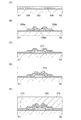
図1(A)は、半導体装置の構成の一例である。トランジスタ250は、基板200上に設けられた酸化物半導体層206aと、酸化物半導体層206aと電気的に接続されているソース電極またはドレイン電極208a、およびソース電極またはドレイン電極208bと、酸化物半導体層206a、ソース電極またはドレイン電極208a、およびソース電極またはドレイン電極208bを覆うように設けられたゲート絶縁層212と、ゲート絶縁層212上に、酸化物半導体層206aと重畳するように設けられたゲート電極214と、を有する。また、トランジスタ250を覆うように層間絶縁層216および層間絶縁層218が設けられている。なお、基板200と酸化物半導体層206aとの間には、下地として機能する絶縁層202を設けてもよい。
FIG. 1A illustrates an example of a structure of a semiconductor device. The
トランジスタ250において、酸化物半導体層206aは、非晶質構造とする。また、トランジスタ250のチャネル長(L)は、10nm以上1000nm以下、好ましくは10nm以上70nm以下とする。トランジスタのチャネル長を短くすることで、動作の高速化、消費電力の低減などの効果が得られるためである。また、酸化物半導体層206aの厚さ(tos)は、1nm以上50nm以下、好ましくは1nm以上30nm以下、より好ましくは1nm以上10nm以下(例えば、3nm以上10nm以下)とする。このような厚さの酸化物半導体層206aを用いることで、微細化に伴う短チャネル効果を抑制することが可能となるためである。
In the
ゲート絶縁層212の厚さ(tox)は、ゲート絶縁層212に用いられる材料の比誘電率をεr、ゲート絶縁層212の厚さをdとして、εr/dが、0.08(nm−1)以上7.9(nm−1)以下、好ましくはεr/dが、0.26(nm−1)以上7.9(nm−1)以下、より好ましくはεr/dが、1.3(nm−1)以上7.9(nm−1)以下の関係を満たす厚さにすればよい。当該関係を満たすことにより、トランジスタの動作を十分に確保することができる。例えば、ゲート絶縁層212に酸化シリコン(比誘電率は約3.9と仮定)を用いる場合には、0.5nm以上50nm以下、好ましくは0.5nm以上15nm以下、より好ましくは0.5nm以上3nm以下とすることができる。
The thickness (tox) of the
なお、ゲート絶縁層212の材料としては、酸化ハフニウム、酸化タンタル等の高誘電率(high−k)材料を用いると良い。このような材料を用いることで、ゲート絶縁層212の厚さを十分に確保しても上述の式を満たすことが可能であり、トランジスタの動作を犠牲にすることなくゲートリークを抑制することができる。
Note that as a material of the
図1(B)は、図1(A)に示す半導体装置の変形例である。トランジスタ350は、基板300上に設けられた第1の酸化物半導体層304aおよび第2の酸化物半導体層306aと、第1の酸化物半導体層304aおよび第2の酸化物半導体層306aと電気的に接続されているソース電極またはドレイン電極308a、およびソース電極またはドレイン電極308bと、第2の酸化物半導体層306a、ソース電極またはドレイン電極308a、およびソース電極またはドレイン電極308bを覆うように設けられたゲート絶縁層312と、ゲート絶縁層312上に、第2の酸化物半導体層306aと重畳するように設けられたゲート電極314と、を有する。また、トランジスタ350を覆うように層間絶縁層316および層間絶縁層318が設けられている。なお、基板300と第1の酸化物半導体層304aとの間には、下地として機能する絶縁層302を設けてもよい。
FIG. 1B illustrates a modification of the semiconductor device illustrated in FIG. The
図1(B)に示す構成と、図1(A)に示す構成との相違は、酸化物半導体層の結晶性にある。図1(A)に示す酸化物半導体層206aの結晶性は非晶質であるが、図1(B)に示す第1の酸化物半導体層304aおよび第2の酸化物半導体層306aは、いずれも結晶領域を有する構造である。当該結晶領域は、酸化物半導体層の表面に略平行なa−b面を有し、該表面に対して略垂直な方向にc軸配向する結晶を含む場合がある。ここで、略平行とは、平行方向から±10°以内の状態をいうものとし、略垂直とは、垂直方向から±10°以内の状態をいうものとする。
A difference between the structure illustrated in FIG. 1B and the structure illustrated in FIG. 1A is in the crystallinity of the oxide semiconductor layer. Although the crystallinity of the
図1(B)に示すように、結晶領域を有する酸化物半導体層をトランジスタに用いることで、電界効果移動度μ>100cm2/V・sが達成可能である。このため、図1(B)に示す半導体装置は、高速動作が要求される論理回路などに適している。 As illustrated in FIG. 1B, field-effect mobility μ> 100 cm 2 / V · s can be achieved by using an oxide semiconductor layer having a crystalline region for a transistor. Therefore, the semiconductor device illustrated in FIG. 1B is suitable for a logic circuit or the like that requires high-speed operation.
トランジスタのチャネル長、酸化物半導体層の厚さ、ゲート絶縁層の厚さ、などの条件に関しては、図1(A)と同様である。 The conditions such as the channel length of the transistor, the thickness of the oxide semiconductor layer, and the thickness of the gate insulating layer are the same as those in FIG.
なお、図1(B)では、酸化物半導体層を2層構造とする場合について説明したが、開示する発明の一態様は当該構造に限定されない。第1の酸化物半導体層304aのみで必要な厚さを確保できる場合には、第2の酸化物半導体層306aは不要である。つまり、酸化物半導体層を、結晶領域を有する酸化物半導体層の単層構造としてもよい。
Note that although FIG. 1B illustrates the case where the oxide semiconductor layer has a two-layer structure, one embodiment of the disclosed invention is not limited to the structure. In the case where a necessary thickness can be ensured only by the first
図1(C)は、図1(A)に示す半導体装置の変形例である。トランジスタ450は、基板400上に設けられた酸化物半導体層406aと、酸化物半導体層406aと電気的に接続されているソース電極またはドレイン電極408a、およびソース電極またはドレイン電極408bと、ソース電極またはドレイン電極408a、およびソース電極またはドレイン電極408bの上部を覆う絶縁層410a、および絶縁層410bと、酸化物半導体層406a、ソース電極またはドレイン電極408a、およびソース電極またはドレイン電極408bなどを覆うように設けられたゲート絶縁層412と、ゲート絶縁層412上に、酸化物半導体層406aと重畳するように設けられたゲート電極414と、を有する。また、トランジスタ450を覆うように層間絶縁層416および層間絶縁層418が設けられている。なお、基板400と酸化物半導体層406aとの間には、下地として機能する絶縁層402を設けてもよい。
FIG. 1C illustrates a modification of the semiconductor device illustrated in FIG. The
図1(C)に示す構成と、図1(A)に示す構成との相違は、絶縁層410a、絶縁層410bの有無にある。絶縁層410a、および絶縁層410bを設けることにより、ゲート電極414とソース電極またはドレイン電極408a、およびゲート電極414とソース電極またはドレイン電極408bとによって形成される容量を低減させることができる。
A difference between the structure illustrated in FIG. 1C and the structure illustrated in FIG. 1A is in the presence or absence of the insulating
また、ソース電極またはドレイン電極408a、およびソース電極またはドレイン電極408bは、ゲート絶縁層412と接する部分に、酸化領域411a、および酸化領域411bを有する。当該酸化領域を有することにより、ゲート絶縁層の薄型化やカバレッジ不良などに起因して生じ得る、ゲート電極414とソース電極またはドレイン電極408a、およびゲート電極414とソース電極またはドレイン電極408bとのショートを防止することが可能である。また、酸化物半導体層406aとソース電極またはドレイン電極408a、および酸化物半導体層406aとソース電極またはドレイン電極408bとの界面における電界を、低く抑えることが可能である。
In addition, the source or
トランジスタのチャネル長、酸化物半導体層の厚さ、ゲート絶縁層の厚さ、などの条件に関しては、図1(A)と同様である。 The conditions such as the channel length of the transistor, the thickness of the oxide semiconductor layer, and the thickness of the gate insulating layer are the same as those in FIG.
図1(D)は、図1(B)に示す半導体装置の変形例である。または、図1(C)に示す半導体装置の変形例である。トランジスタ550は、基板500上に設けられた第1の酸化物半導体層504a、第2の酸化物半導体層506aと、第1の酸化物半導体層504a、および第2の酸化物半導体層506aと電気的に接続されているソース電極またはドレイン電極508a、およびソース電極またはドレイン電極508bと、ソース電極またはドレイン電極508a、およびソース電極またはドレイン電極508bの上部を覆う絶縁層510a、および絶縁層510bと、第2の酸化物半導体層506a、ソース電極またはドレイン電極508a、およびソース電極またはドレイン電極508bなどを覆うように設けられたゲート絶縁層512と、ゲート絶縁層512上に、第2の酸化物半導体層506aと重畳するように設けられたゲート電極514と、を有する。また、トランジスタ550を覆うように層間絶縁層516および層間絶縁層518が設けられている。なお、基板500と第2の酸化物半導体層506aとの間には、下地として機能する絶縁層502を設けてもよい。
FIG. 1D illustrates a modified example of the semiconductor device illustrated in FIG. Alternatively, the semiconductor device is a modification of the semiconductor device illustrated in FIG. The
図1(D)に示す構成と、図1(B)に示す構成との相違は、絶縁層510a、絶縁層510bの有無にある。絶縁層510a、および絶縁層510bを設けることにより、ゲート電極514と、ソース電極またはドレイン電極508a、およびゲート電極514と、ソース電極またはドレイン電極508bとによって形成される容量を低減させることができる。
A difference between the structure illustrated in FIG. 1D and the structure illustrated in FIG. 1B is in the presence or absence of the insulating
また、ソース電極またはドレイン電極508a、およびソース電極またはドレイン電極508bにおいて、ゲート絶縁層512と接する部分に、酸化領域511a、酸化領域511bが設けられている。当該酸化領域を有することにより、ゲート絶縁層の薄型化やカバレッジ不良などに起因して生じ得る、ゲート電極と、ソース電極またはドレイン電極のショートを防止することが可能である。
In addition, in the source or
また、図1(D)に示す構成と、図1(C)に示す構成との相違は、酸化物半導体層の結晶性にある。図1(D)に示す第1の酸化物半導体層504a、第2の酸化物半導体層506aは、いずれも結晶領域を有する構造である。当該結晶領域は、酸化物半導体層の表面に略平行なa−b面を有し、該表面に対して略垂直な方向にc軸配向する結晶を含む場合がある。ここで、略平行とは、平行方向から±10°以内の状態をいうものとし、略垂直とは、垂直方向から±10°以内の状態をいうものとする。
A difference between the structure illustrated in FIG. 1D and the structure illustrated in FIG. 1C is in the crystallinity of the oxide semiconductor layer. Each of the first
図1(D)に示すように、結晶領域を有する酸化物半導体層をトランジスタに用いることで、電界効果移動度μ>100cm2/V・sが達成可能である。このため、図1(D)に示す半導体装置は、高速動作が要求される論理回路などに適している。 As illustrated in FIG. 1D, field-effect mobility μ> 100 cm 2 / V · s can be achieved by using an oxide semiconductor layer having a crystalline region for a transistor. Therefore, the semiconductor device illustrated in FIG. 1D is suitable for a logic circuit or the like that requires high-speed operation.
トランジスタのチャネル長、酸化物半導体層の厚さ、ゲート絶縁層の厚さ、などの条件に関しては、図1(A)と同様である。 The conditions such as the channel length of the transistor, the thickness of the oxide semiconductor layer, and the thickness of the gate insulating layer are the same as those in FIG.
なお、図1(D)では、酸化物半導体層を2層構造とする場合について説明したが、開示する発明の一態様は当該構造に限定されない。第1の酸化物半導体層504aのみで必要な厚さを確保できる場合には、第2の酸化物半導体層506aは不要である。つまり、酸化物半導体層を、結晶領域を有する酸化物半導体層の単層構造としてもよい。
Note that although FIG. 1D illustrates the case where the oxide semiconductor layer has a two-layer structure, one embodiment of the disclosed invention is not limited to the structure. In the case where a necessary thickness can be ensured only by the first
本実施の形態に示す構成は微細化に適したものであり、当該構成を用いることにより、酸化物半導体を用いた半導体装置の良好な特性を維持しつつ、微細化が実現可能である。 The structure described in this embodiment is suitable for miniaturization, and by using the structure, miniaturization can be realized while maintaining favorable characteristics of a semiconductor device including an oxide semiconductor.
本実施の形態に示す構成、方法などは、他の実施の形態に示す構成、方法などと適宜組み合わせて用いることができる。 The structures, methods, and the like described in this embodiment can be combined as appropriate with any of the structures, methods, and the like described in the other embodiments.
(実施の形態2)
本実施の形態では、酸化物半導体(特に非晶質構造)を用いた半導体装置の作製方法、具体的には、図1(A)に相当する半導体装置の作製方法について、図2を用いて説明する。なお、以下では、トップゲート型のトランジスタを例に挙げて説明するが、トランジスタの構成をトップゲート型に限る必要はない。
(Embodiment 2)
In this embodiment, a method for manufacturing a semiconductor device using an oxide semiconductor (particularly, an amorphous structure), specifically, a method for manufacturing a semiconductor device corresponding to FIG. 1A will be described with reference to FIGS. explain. In the following description, a top-gate transistor is described as an example. However, the structure of the transistor is not necessarily limited to the top-gate transistor.
まず、基板200上に絶縁層202を形成する。その後、絶縁層202上に酸化物半導体層206を形成する(図2(A)参照)。
First, the insulating
基板200には、例えば、ガラス基板を用いることができる。基板200には、ガラス基板の他にも、セラミック基板、石英基板、サファイア基板等の絶縁体でなる絶縁性基板や、シリコン等の半導体材料でなる半導体基板、金属やステンレス等の導電体でなる導電性基板、これらの表面を絶縁材料で被覆したもの、などを用いることができる。また、プラスチック等の可撓性を有する基板は、耐熱温度が一般的に低い傾向があるが、後の作製工程に耐えられるのであれば、基板200として用いることが可能である。
For the
なお、基板200は、算術平均粗さ(Ra)が1nm以下のものを用いるのが望ましい。より望ましくは、0.5nm以下である。半導体装置の微細化に伴い、パターニングに用いるマスクの露光条件の要求は高まるが、このような平坦性の高い基板を用いることで、露光条件の要求が高い場合でも、対応が容易になるためである。なお、上述の算術平均粗さには、例えば、10μm×10μmの領域において測定した値を用いることができる。
Note that the
絶縁層202は下地として機能するものであり、PVD法やCVD法などを用いて形成することができる。また、絶縁層202は、酸化シリコン、酸窒化シリコン、窒化シリコン、酸化ハフニウム、酸化アルミニウム、酸化タンタル等の無機絶縁材料を含む材料を用いて形成することができる。なお、絶縁層202は、できるだけ水素や水を含まないように形成することが望ましい。また、絶縁層202を設けない構成とすることも可能である。
The insulating
酸化物半導体層206は、四元系金属の酸化物であるIn−Sn−Ga−Zn−O系や、三元系金属の酸化物であるIn−Ga−Zn−O系、In−Sn−Zn−O系、In−Al−Zn−O系、Sn−Ga−Zn−O系、Al−Ga−Zn−O系、Sn−Al−Zn−O系や、二元系金属の酸化物であるIn−Zn−O系、Sn−Zn−O系、Al−Zn−O系、Zn−Mg−O系、Sn−Mg−O系、In−Mg−O系や、In−O系、Sn−O系、Zn−O系などの酸化物半導体を用いて形成することができる。
The
中でも、In−Ga−Zn−O系の酸化物半導体材料は、無電界時の抵抗が十分に高くオフ電流を十分に小さくすることが可能であり、また、電界効果移動度も高いため、半導体装置に用いる半導体材料としては好適である。 Among them, an In—Ga—Zn—O-based oxide semiconductor material has a sufficiently high resistance when no electric field is applied and can have a sufficiently small off-state current. It is suitable as a semiconductor material used for the apparatus.
In−Ga−Zn−O系の酸化物半導体材料の代表例としては、InGaO3(ZnO)m(m>0)で表記されるものがある。また、Gaに代えてMを用い、InMO3(ZnO)m(m>0)のように表記される酸化物半導体材料がある。ここで、Mは、ガリウム(Ga)、アルミニウム(Al)、鉄(Fe)、ニッケル(Ni)、マンガン(Mn)、コバルト(Co)などから選ばれた一の金属元素または複数の金属元素を示す。例えば、Mとしては、Ga、GaおよびAl、GaおよびFe、GaおよびNi、GaおよびMn、GaおよびCoなどを適用することができる。なお、上述の組成は結晶構造から導き出されるものであり、あくまでも一例に過ぎないことを付記する。 As a typical example of the In—Ga—Zn—O-based oxide semiconductor material, one represented by InGaO 3 (ZnO) m (m> 0) is given. In addition, there is an oxide semiconductor material in which M is used instead of Ga and is represented as InMO 3 (ZnO) m (m> 0). Here, M represents one metal element or a plurality of metal elements selected from gallium (Ga), aluminum (Al), iron (Fe), nickel (Ni), manganese (Mn), cobalt (Co), and the like. Show. For example, as M, Ga, Ga and Al, Ga and Fe, Ga and Ni, Ga and Mn, Ga and Co, and the like can be applied. It should be noted that the above composition is derived from the crystal structure and is merely an example.
酸化物半導体層206をスパッタ法で作製するためのターゲットとしては、In:Ga:Zn=1:x:y(xは0以上、yは0.5以上5以下)の組成比を有するものを用いるのが好適である。例えば、In:Ga:Zn=1:1:1[atom比](x=1、y=1)、(すなわち、In2O3:Ga2O3:ZnO=1:1:2[mol数比])の組成比を有するターゲットなどを用いることができる。また、In:Ga:Zn=1:1:0.5[atom比](x=1、y=0.5)、(すなわち、In2O3:Ga2O3:ZnO=1:1:1[mol数比])の組成比を有するターゲットや、In:Ga:Zn=1:1:2[atom比](x=1、y=2)、(すなわち、In2O3:Ga2O3:ZnO=1:1:4[mol数比])の組成比を有するターゲットや、In:Ga:Zn=1:0:1[atom比](x=0、y=1)、(すなわち、In2O3:ZnO=1:2[mol数比])の組成比を有するターゲットを用いることもできる。
As a target for forming the
本実施の形態では、非晶質構造の酸化物半導体層206を、In−Ga−Zn−O系の金属酸化物ターゲットを用いるスパッタ法により形成することとする。
In this embodiment, the
金属酸化物ターゲット中の金属酸化物の相対密度は80%以上、好ましくは95%以上、さらに好ましくは99.9%以上である。相対密度の高い金属酸化物ターゲットを用いることにより、緻密な構造の酸化物半導体層206を形成することが可能である。
The relative density of the metal oxide in the metal oxide target is 80% or more, preferably 95% or more, more preferably 99.9% or more. By using a metal oxide target having a high relative density, the
酸化物半導体層206の形成雰囲気は、希ガス(代表的にはアルゴン)雰囲気、酸素雰囲気、または、希ガス(代表的にはアルゴン)と酸素との混合雰囲気とするのが好適である。具体的には、例えば、水素、水、水酸基、水素化物などの不純物が、濃度1ppm以下(望ましくは濃度10ppb以下)にまで除去された高純度ガス雰囲気を用いるのが好適である。
The atmosphere in which the
酸化物半導体層206の形成の際には、例えば、減圧状態に保持された処理室内に基板を保持し、基板の温度が100℃以上550℃未満、好ましくは200℃以上400℃以下となるように基板を熱する。または、酸化物半導体層206の形成の際の基板の温度は、室温としてもよい。そして、処理室内の水分を除去しつつ、水素や水などが除去されたスパッタガスを導入し、上記ターゲットを用いて酸化物半導体層206を形成する。基板を熱しながら酸化物半導体層206を形成することにより、酸化物半導体層206に含まれる不純物を低減することができる。また、スパッタによる損傷を軽減することができる。処理室内の水分を除去するためには、吸着型の真空ポンプを用いることが好ましい。例えば、クライオポンプ、イオンポンプ、チタンサブリメーションポンプなどを用いることができる。また、ターボポンプにコールドトラップを加えたものを用いてもよい。クライオポンプなどを用いて排気することで、処理室から水素や水などを除去することができるため、酸化物半導体層206中の不純物濃度を低減できる。
When forming the
酸化物半導体層206の形成条件としては、例えば、基板とターゲットの間との距離が170mm、圧力が0.4Pa、直流(DC)電力が0.5kW、雰囲気が酸素(酸素100%)雰囲気、またはアルゴン(アルゴン100%)雰囲気、または酸素とアルゴンの混合雰囲気、といった条件を適用することができる。なお、パルス直流(DC)電源を用いると、ごみ(成膜時に形成される粉状の物質など)を低減でき、膜厚分布も均一となるため好ましい。酸化物半導体層206の厚さは、1nm以上50nm以下、好ましくは1nm以上30nm以下、より好ましくは1nm以上10nm以下(例えば、3nm以上10nm以下)とする。このような厚さの酸化物半導体層206を用いることで、微細化に伴う短チャネル効果を抑制することが可能である。ただし、適用する酸化物半導体材料や、半導体装置の用途などにより適切な厚さは異なるから、その厚さは、用いる材料や用途などに応じて選択することもできる。
As a formation condition of the
なお、酸化物半導体層206をスパッタ法により形成する前には、アルゴンガスを導入してプラズマを発生させる逆スパッタを行い、形成表面(例えば絶縁層202の表面)の付着物を除去するのが好適である。ここで、逆スパッタとは、通常のスパッタにおいては、スパッタターゲットにイオンを衝突させるところ、逆に、処理表面にイオンを衝突させることによってその表面を改質する方法のことをいう。処理表面にイオンを衝突させる方法としては、アルゴン雰囲気下で処理表面側に高周波電圧を印加して、基板付近にプラズマを生成する方法などがある。なお、アルゴン雰囲気に代えて窒素、ヘリウム、酸素などによる雰囲気を適用してもよい。
Note that before the
次に、マスクを用いたエッチングなどの方法によって酸化物半導体層206を加工して、島状の酸化物半導体層206aを形成する。
Next, the
酸化物半導体層206のエッチングには、ドライエッチング、ウェットエッチングのいずれを用いても良い。もちろん、その両方を組み合わせて用いることもできる。酸化物半導体層を所望の形状にエッチングできるよう、材料に合わせてエッチング条件(エッチングガスやエッチング液、エッチング時間、温度等)は適宜設定する。
For the etching of the
ドライエッチングに用いるエッチングガスには、例えば、塩素を含むガス(塩素系ガス、例えば、塩素(Cl2)、三塩化硼素(BCl3)、四塩化珪素(SiCl4)、四塩化炭素(CCl4)など)がある。また、フッ素を含むガス(フッ素系ガス、例えば四弗化炭素(CF4)、六弗化硫黄(SF6)、三弗化窒素(NF3)、トリフルオロメタン(CHF3)など)、臭化水素(HBr)、酸素(O2)、これらのガスにヘリウム(He)やアルゴン(Ar)などの希ガスを添加したガス、などを用いても良い。 Examples of the etching gas used for dry etching include a gas containing chlorine (chlorine-based gas such as chlorine (Cl 2 ), boron trichloride (BCl 3 ), silicon tetrachloride (SiCl 4 ), and carbon tetrachloride (CCl 4). )and so on. Gas containing fluorine (fluorine-based gas such as carbon tetrafluoride (CF 4 ), sulfur hexafluoride (SF 6 ), nitrogen trifluoride (NF 3 ), trifluoromethane (CHF 3 ), etc.), bromide Hydrogen (HBr), oxygen (O 2 ), or a gas obtained by adding a rare gas such as helium (He) or argon (Ar) to these gases may be used.
ドライエッチング法としては、平行平板型RIE(Reactive Ion Etching)法や、ICP(Inductively Coupled Plasma:誘導結合型プラズマ)エッチング法を用いることができる。所望の形状にエッチングできるように、エッチング条件(コイル型の電極に印加される電力量、基板側の電極に印加される電力量、基板側の電極温度等)は適宜設定する。 As the dry etching method, a parallel plate RIE (Reactive Ion Etching) method or an ICP (Inductively Coupled Plasma) etching method can be used. Etching conditions (such as the amount of power applied to the coil-type electrode, the amount of power applied to the electrode on the substrate side, and the electrode temperature on the substrate side) are set as appropriate so that the film can be etched into a desired shape.
ウェットエッチングに用いるエッチング液としては、燐酸と酢酸と硝酸を混ぜた溶液、アンモニア過水(31重量%過酸化水素水:28重量%アンモニア水:水=5:2:2)などを用いることができる。また、ITO07N(関東化学社製)などのエッチング液を用いてもよい。 As an etchant used for wet etching, a mixed solution of phosphoric acid, acetic acid, and nitric acid, ammonia perwater (31 wt% hydrogen peroxide solution: 28 wt% ammonia water: water = 5: 2: 2), or the like may be used. it can. An etching solution such as ITO07N (manufactured by Kanto Chemical Co., Inc.) may be used.
酸化物半導体層206aの端部は、テーパー形状となるようにエッチングすることが好ましい。ここで、テーパー角は、例えば、30°以上60°以下であることが好ましい。なお、テーパー角とは、テーパー形状を有する層(例えば、酸化物半導体層206a)を、その断面(基板の表面と直交する面)に垂直な方向から観察した際に、当該層の側面と底面がなす傾斜角を示す。酸化物半導体層206aの端部をテーパー形状となるようにエッチングすることにより、後に形成されるソース電極またはドレイン電極208a、ソース電極またはドレイン電極208bの被覆性を向上させ、段切れを防止することができる。
The end portion of the
その後、酸化物半導体層206aに対して、熱処理(第1の熱処理)を行うことが望ましい。この第1の熱処理によって酸化物半導体層206a中の、過剰な水素(水や水酸基を含む)を除去し、酸化物半導体層206aの構造を整え、エネルギーギャップ中の欠陥準位を低減させることができる。第1の熱処理の温度は、例えば、300℃以上550℃未満、または400℃以上500℃以下とする。なお、ここで示すように、熱処理(第1の熱処理)をエッチング後に行う場合には、ウェットエッチングを用いる場合であっても、エッチングレートが高い状態でエッチングを行うことができるため、エッチングにかかる時間を短縮させることができるというメリットがある。
After that, heat treatment (first heat treatment) is preferably performed on the
熱処理は、例えば、抵抗発熱体などを用いた電気炉に基板200を導入し、窒素雰囲気下、450℃、1時間の条件で行うことができる。この間、酸化物半導体層206aは大気に触れさせず、水や水素の混入が生じないようにする。
The heat treatment can be performed, for example, by introducing the
熱処理装置は電気炉に限る必要はなく、加熱されたガスなどの媒体からの熱伝導、または熱輻射によって、被処理物を加熱する装置を用いても良い。例えば、GRTA(Gas Rapid Thermal Anneal)装置、LRTA(Lamp Rapid Thermal Anneal)装置等のRTA(Rapid Thermal Anneal)装置を用いることができる。LRTA装置は、ハロゲンランプ、メタルハライドランプ、キセノンアークランプ、カーボンアークランプ、高圧ナトリウムランプ、高圧水銀ランプなどのランプから発する光(電磁波)の輻射により、被処理物を加熱する装置である。GRTA装置は、高温のガスを用いて熱処理を行う装置である。ガスとしては、アルゴンなどの希ガス、または窒素のような、熱処理によって被処理物と反応しない不活性気体が用いられる。 The heat treatment apparatus is not limited to an electric furnace, and an apparatus for heating an object to be processed by heat conduction or heat radiation from a medium such as a heated gas may be used. For example, a rapid thermal annealing (RTA) device such as a GRTA (Gas Rapid Thermal Anneal) device or an LRTA (Lamp Rapid Thermal Anneal) device can be used. The LRTA apparatus is an apparatus that heats an object to be processed by radiation of light (electromagnetic waves) emitted from a lamp such as a halogen lamp, a metal halide lamp, a xenon arc lamp, a carbon arc lamp, a high pressure sodium lamp, or a high pressure mercury lamp. The GRTA apparatus is an apparatus that performs heat treatment using a high-temperature gas. As the gas, an inert gas that does not react with an object to be processed by heat treatment, such as nitrogen or a rare gas such as argon, is used.
例えば、第1の熱処理として、熱せられた不活性ガス雰囲気中に基板を投入し、数分間熱した後、当該不活性ガス雰囲気から基板を取り出すGRTA処理を行ってもよい。GRTA処理を用いると短時間での高温熱処理が可能となる。また、短時間の熱処理であるため、基板の耐熱温度を超える温度条件であっても適用が可能となる。なお、処理中に、不活性ガスを、酸素を含むガスに切り替えても良い。酸素を含む雰囲気において第1の熱処理を行うことで、酸素欠損に起因するエネルギーギャップ中の欠陥準位を低減させることができるためである。 For example, as the first heat treatment, a GRTA process may be performed in which the substrate is placed in a heated inert gas atmosphere, heated for several minutes, and then the substrate is taken out from the inert gas atmosphere. When GRTA treatment is used, high-temperature heat treatment can be performed in a short time. Further, since the heat treatment is performed for a short time, it can be applied even under a temperature condition exceeding the heat resistance temperature of the substrate. Note that the inert gas may be switched to a gas containing oxygen during the treatment. This is because the defect level in the energy gap due to oxygen deficiency can be reduced by performing the first heat treatment in an atmosphere containing oxygen.
なお、不活性ガス雰囲気としては、窒素、または希ガス(ヘリウム、ネオン、アルゴン等)を主成分とする雰囲気であって、水、水素などが含まれない雰囲気を適用するのが望ましい。例えば、熱処理装置に導入する窒素や、ヘリウム、ネオン、アルゴン等の希ガスの純度を、6N(99.9999%)以上、好ましくは7N(99.99999%)以上(すなわち、不純物濃度が1ppm以下、好ましくは0.1ppm以下)とする。 Note that as the inert gas atmosphere, an atmosphere containing nitrogen or a rare gas (such as helium, neon, or argon) as a main component and not including water, hydrogen, or the like is preferably used. For example, the purity of nitrogen or a rare gas such as helium, neon, or argon introduced into the heat treatment apparatus is 6N (99.9999%) or more, preferably 7N (99.99999%) or more (that is, the impurity concentration is 1 ppm or less). , Preferably 0.1 ppm or less).
いずれにしても、第1の熱処理によって不純物を低減し、i型(真性半導体)またはi型に限りなく近い酸化物半導体層206aを形成することで、極めて優れた特性のトランジスタを実現することができる。
In any case, a transistor with extremely excellent characteristics can be realized by reducing impurities by the first heat treatment and forming the
なお、第1の熱処理は、島状の酸化物半導体層206aに加工する前の酸化物半導体層206に行うこともできる。その場合には、第1の熱処理後に、加熱装置から基板200を取り出し、フォトリソグラフィ工程を行うことになる。
Note that the first heat treatment can be performed on the
ところで、上述の熱処理(第1の熱処理)には水素や水などを除去する効果があるから、当該熱処理を、脱水化処理、脱水素化処理などと呼ぶこともできる。当該脱水化処理、脱水素化処理は、酸化物半導体層206aの形成後や酸化物半導体層206a上にソース電極またはドレイン電極を積層させた後、などのタイミングにおいて行うことも可能である。また、このような脱水化処理、脱水素化処理は、一回に限らず複数回行っても良い。
By the way, since the above heat treatment (first heat treatment) has an effect of removing hydrogen, water, and the like, the heat treatment can also be referred to as dehydration treatment, dehydrogenation treatment, or the like. The dehydration treatment and dehydrogenation treatment can be performed at a timing such as after the
次に、酸化物半導体層206aに接するように導電層を形成する。そして、導電層を選択的にエッチングして、ソース電極またはドレイン電極208a、ソース電極またはドレイン電極208bを形成する(図2(B)参照)。
Next, a conductive layer is formed so as to be in contact with the
導電層は、スパッタ法をはじめとするPVD法や、プラズマCVD法などのCVD法を用いて形成することができる。また、導電層の材料としては、アルミニウム、クロム、銅、タンタル、チタン、モリブデン、タングステンから選ばれた元素や、上述した元素を成分とする合金等を用いることができる。マンガン、マグネシウム、ジルコニウム、ベリリウムのいずれか一または複数から選択された材料を用いてもよい。また、アルミニウムに、チタン、タンタル、タングステン、モリブデン、クロム、ネオジム、スカンジウムから選ばれた元素を単数、または複数組み合わせた材料を用いてもよい。 The conductive layer can be formed by a PVD method such as a sputtering method or a CVD method such as a plasma CVD method. As a material for the conductive layer, an element selected from aluminum, chromium, copper, tantalum, titanium, molybdenum, and tungsten, an alloy containing the above-described element as a component, or the like can be used. A material selected from one or more of manganese, magnesium, zirconium, and beryllium may be used. Alternatively, a material obtained by combining one or more elements selected from titanium, tantalum, tungsten, molybdenum, chromium, neodymium, and scandium with aluminum may be used.
導電層は、単層構造であっても良いし、2層以上の積層構造としてもよい。例えば、チタン膜や窒化チタン膜の単層構造、シリコンを含むアルミニウム膜の単層構造、アルミニウム膜上にチタン膜が積層された2層構造、窒化チタン膜上にチタン膜が積層された2層構造、チタン膜とアルミニウム膜とチタン膜とが積層された3層構造などが挙げられる。なお、導電層を、チタン膜や窒化チタン膜の単層構造とする場合には、テーパー形状を有するソース電極またはドレイン電極208a、およびソース電極またはドレイン電極208bへの加工が容易であるというメリットがある。
The conductive layer may have a single layer structure or a stacked structure of two or more layers. For example, a single-layer structure of a titanium film or a titanium nitride film, a single-layer structure of an aluminum film containing silicon, a two-layer structure in which a titanium film is laminated on an aluminum film, or a two-layer structure in which a titanium film is laminated on a titanium nitride film Examples of the structure include a three-layer structure in which a titanium film, an aluminum film, and a titanium film are stacked. Note that in the case where the conductive layer has a single-layer structure of a titanium film or a titanium nitride film, there is an advantage that processing into the source or
また、導電層は、導電性の金属酸化物を用いて形成しても良い。導電性の金属酸化物としては酸化インジウム(In2O3)、酸化スズ(SnO2)、酸化亜鉛(ZnO)、酸化インジウム酸化スズ合金(In2O3―SnO2、ITOと略記する場合がある)、酸化インジウム酸化亜鉛合金(In2O3―ZnO)、または、これらの金属酸化物材料にシリコン若しくは酸化シリコンを含有させたものを用いることができる。 The conductive layer may be formed using a conductive metal oxide. The conductive metal oxide may be abbreviated as indium oxide (In 2 O 3 ), tin oxide (SnO 2 ), zinc oxide (ZnO), indium oxide tin oxide alloy (In 2 O 3 —SnO 2 , ITO). Or indium oxide-zinc oxide alloy (In 2 O 3 —ZnO), or a metal oxide material containing silicon or silicon oxide.
導電層のエッチングは、形成されるソース電極またはドレイン電極208a、およびソース電極またはドレイン電極208bの端部が、テーパー形状となるように行うことが好ましい。ここで、テーパー角は、例えば、30°以上60°以下であることが好ましい。ソース電極またはドレイン電極208a、ソース電極またはドレイン電極208bの端部をテーパー形状となるようにエッチングすることにより、後に形成されるゲート絶縁層212の被覆性を向上し、段切れを防止することができる。
The conductive layer is preferably etched so that end portions of the source or
トランジスタのチャネル長(L)は、ソース電極またはドレイン電極208a、およびソース電極またはドレイン電極208bの下端部との間隔によって決定される。なお、チャネル長(L)が25nm未満の際に、露光を行う場合には、数nm〜数10nmと波長の短い超紫外線(Extreme Ultraviolet)を用いてマスク形成の露光を行うのが望ましい。超紫外線による露光は、解像度が高く焦点深度も大きい。従って、後に形成されるトランジスタのチャネル長(L)を、10nm以上1000nm(1μm)以下、例えば、10nm以上70nm以下とすることも可能であり、回路の動作速度を高めることが可能である。また、微細化によって、半導体装置の消費電力を低減させることも可能である。
The channel length (L) of the transistor is determined by the distance between the source or
なお、ソース電極またはドレイン電極208a、およびソース電極またはドレイン電極208bの上には、絶縁層を形成しても良い。当該絶縁層を設けることにより、後に形成されるゲート電極と、ソース電極またはドレイン電極208a、およびソース電極またはドレイン電極208bとの間の寄生容量を低減させることが可能である。
Note that an insulating layer may be formed over the source or
次に、酸化物半導体層206aの一部に接するゲート絶縁層212を形成する(図2(C)参照)。ゲート絶縁層212は、CVD法やスパッタ法等を用いて形成することができる。また、ゲート絶縁層212は、酸化シリコン、窒化シリコン、酸窒化シリコン、酸化アルミニウム、酸化タンタル、酸化ハフニウム、酸化イットリウム、ハフニウムシリケート(HfSixOy(x>0、y>0))、窒素が添加されたハフニウムシリケート(HfSixOy(x>0、y>0))、窒素が添加されたハフニウムアルミネート(HfAlxOy(x>0、y>0))、などを含むように形成するのが好適である。ゲート絶縁層212は、単層構造としても良いし、積層構造としても良い。また、半導体装置を微細化する場合には、トランジスタの動作を確保するために薄くするのが望ましい。例えば、酸化シリコンを用いる場合には、0.5nm以上50nm以下、好ましくは0.5nm以上15nm以下、より好ましくは0.5nm以上3nm以下とすることができる。
Next, the
上述のように、ゲート絶縁膜を薄くすると、トンネル効果などに起因するゲートリークが問題となる。ゲートリークの問題を解消するには、ゲート絶縁層212に、酸化ハフニウム、酸化タンタル、酸化イットリウム、ハフニウムシリケート(HfSixOy(x>0、y>0))、窒素が添加されたハフニウムシリケート(HfSixOy(x>0、y>0))、窒素が添加されたハフニウムアルミネート(HfAlxOy(x>0、y>0))、などの高誘電率(high−k)材料を用いると良い。高誘電率(high−k)材料をゲート絶縁層212に用いることで、電気的特性を確保しつつ、ゲートリークを抑制するために膜厚を大きくすることが可能になる。なお、高誘電率(high−k)材料を含む膜と、酸化シリコン、窒化シリコン、酸化窒化シリコン、窒化酸化シリコン、酸化アルミニウムなどを含む膜との積層構造としてもよい。
As described above, when the gate insulating film is thin, gate leakage due to the tunnel effect or the like becomes a problem. In order to solve the problem of gate leakage, hafnium oxide, tantalum oxide, yttrium oxide, hafnium silicate (HfSixOy (x> 0, y> 0)) and nitrogen-added hafnium silicate (HfSixOy (HfSixOy ( high dielectric constant (high-k) materials such as x> 0, y> 0)) and hafnium aluminate to which nitrogen is added (HfAlxOy (x> 0, y> 0)) are preferably used. By using a high dielectric constant (high-k) material for the
このように、酸化シリコン以外の材料をゲート絶縁層212に用いる場合には、ゲート絶縁層212に用いられる材料の比誘電率をεr、ゲート絶縁層212の厚さをdとして、εr/dが、0.08(nm−1)以上7.9(nm−1)以下、好ましくはεr/dが、0.26(nm−1)以上7.9(nm−1)以下、より好ましくはεr/dが、1.3(nm−1)以上7.9(nm−1)以下の関係を満たす厚さにすればよい。なお、当該条件は、酸化シリコン(比誘電率は約3.9と仮定)を用いる場合において、厚さが0.5nm以上50nm以下、好ましくは0.5nm以上15nm以下、より好ましくは0.5nm以上3nm以下となる条件と概ね等しいものである。
As described above, when a material other than silicon oxide is used for the
ゲート絶縁層212の形成後には、不活性ガス雰囲気下、または酸素雰囲気下で第2の熱処理を行うのが望ましい。熱処理の温度は、200℃以上450℃以下、望ましくは250℃以上350℃以下である。例えば、窒素雰囲気下で250℃、1時間の熱処理を行えばよい。第2の熱処理を行うことによって、トランジスタの電気的特性のばらつきを軽減することができる。また、ゲート絶縁層212が酸素を含む場合、酸化物半導体層206aに酸素を供給し、該酸化物半導体層206aの酸素欠損を補填して、i型(真性半導体)またはi型に限りなく近い酸化物半導体層206aを形成することもできる。
After the
なお、本実施の形態では、ゲート絶縁層212の形成後に第2の熱処理を行っているが、第2の熱処理のタイミングはこれに特に限定されない。例えば、ゲート電極214の形成後に第2の熱処理を行っても良い。
Note that in this embodiment, the second heat treatment is performed after the
次に、ゲート絶縁層212上において酸化物半導体層206aと重畳する領域にゲート電極214を形成する(図2(D)参照)。ゲート電極214は、ゲート絶縁層212上に導電層を形成した後に、当該導電層を選択的にパターニングすることによって形成することができる。ゲート電極214となる導電層は、スパッタ法をはじめとするPVD法や、プラズマCVD法などのCVD法を用いて形成することができる。詳細は、ソース電極またはドレイン電極208a、およびソース電極またはドレイン電極208bなどを形成する場合と同様であり、これらの記載を参酌できる。
Next, the
次に、ゲート絶縁層212およびゲート電極214上に、層間絶縁層216および層間絶縁層218を形成する(図2(E)参照)。層間絶縁層216および層間絶縁層218は、PVD法やCVD法などを用いて形成することができる。また、酸化シリコン、酸窒化シリコン、窒化シリコン、酸化ハフニウム、酸化アルミニウム、酸化タンタル等の無機絶縁材料を含む材料を用いて形成することができる。なお、本実施の形態では、層間絶縁層216と層間絶縁層218の積層構造としているが、開示する発明の一態様はこれに限定されない。1層としても良いし、3層以上の積層構造としても良い。また、層間絶縁層を設けない構成とすることも可能である。
Next, an
なお、上記層間絶縁層218は、その表面が平坦になるように形成することが望ましい。表面が平坦になるように層間絶縁層218を形成することで、半導体装置を微細化した場合などにおいても、層間絶縁層218上に、電極や配線などを好適に形成することができるためである。なお、層間絶縁層218の平坦化は、CMP(化学的機械的研磨)などの方法を用いて行うことができる。
Note that the interlayer insulating
以上により、高純度化された酸化物半導体層206aを用いたトランジスタ250が完成する(図2(E)参照)。
Through the above steps, the
図2(E)に示すトランジスタ250は、基板200上に絶縁層202を介して設けられた酸化物半導体層206aと、酸化物半導体層206aと電気的に接続するソース電極またはドレイン電極208a、ソース電極またはドレイン電極208bと、酸化物半導体層206a、ソース電極またはドレイン電極208a、ソース電極またはドレイン電極208bを覆うゲート絶縁層212と、ゲート絶縁層212上のゲート電極214と、ゲート絶縁層212およびゲート電極214上の層間絶縁層216と、層間絶縁層216上の層間絶縁層218とを有する。
A
本実施の形態において示すトランジスタ250では、酸化物半導体層206aが高純度化されているため、その水素濃度は、5×10¹⁹atoms/cm3以下、望ましくは5×1018atoms/cm3以下、より望ましくは5×1017atoms/cm3以下となる。また、酸化物半導体層206aのキャリア密度は、一般的なシリコンウェハにおけるキャリア密度(1×1014/cm3程度)と比較して、十分に小さい値(例えば、1×1012/cm3未満、より好ましくは、1.45×1010/cm3未満)をとる。そして、これにより、オフ電流が十分に小さくなる。例えば、トランジスタ250の室温でのオフ電流密度(オフ電流をトランジスタのチャネル幅で除した値)は1×10−20A/μm(10zA/μm)から1×10−19A/μm(100zA/μm)程度となる。
In the
このように高純度化され、真性化された酸化物半導体層206aを用いることで、トランジスタのオフ電流を十分に低減することができる。
In this manner, the off-state current of the transistor can be sufficiently reduced by using the
そして、本実施の形態に示すように、酸化物半導体層や、ゲート絶縁層の厚さ、ソース電極とドレイン電極の間隔などを所定の範囲におさめることで、良好な特性を維持しつつ、微細化を達成することができる。 As shown in this embodiment, the oxide semiconductor layer, the thickness of the gate insulating layer, the distance between the source electrode and the drain electrode, and the like are kept within a predetermined range, so that fine characteristics can be maintained while maintaining good characteristics. Can be achieved.
以上、本実施の形態に示す構成、方法などは、他の実施の形態に示す構成、方法などと適宜組み合わせて用いることができる。 The structures, methods, and the like described in this embodiment can be combined as appropriate with any of the structures, methods, and the like described in the other embodiments.
(実施の形態3)
本実施の形態では、酸化物半導体を用いた半導体装置の作製方法について、図3を用いて説明する。本実施の形態では、酸化物半導体層として、結晶領域を有する第1の酸化物半導体層と、第1の酸化物半導体層の結晶領域から結晶成長させた第2の酸化物半導体層を用いる場合、すなわち、図1(B)に相当する半導体装置の作製方法について、詳細に説明する。なお、第1の酸化物半導体層のみで必要な厚さを確保できる場合には、第2の酸化物半導体層は不要である。また、以下では、トップゲート型のトランジスタを例に挙げて説明するが、トランジスタの構成をトップゲート型に限る必要はない。
(Embodiment 3)
In this embodiment, a method for manufacturing a semiconductor device including an oxide semiconductor will be described with reference to FIGS. In this embodiment, as the oxide semiconductor layer, a first oxide semiconductor layer having a crystal region and a second oxide semiconductor layer grown from the crystal region of the first oxide semiconductor layer are used. That is, a method for manufacturing the semiconductor device corresponding to FIG. 1B will be described in detail. Note that the second oxide semiconductor layer is unnecessary when the necessary thickness can be ensured only by the first oxide semiconductor layer. In the following, a top gate type transistor will be described as an example. However, the transistor structure is not necessarily limited to the top gate type.
まず、基板300上に絶縁層302を形成する。それから、絶縁層302上に第1の酸化物半導体層を形成し、第1の熱処理によって少なくとも第1の酸化物半導体層の表面を含む領域を結晶化させて、第1の酸化物半導体層304を形成する(図3(A)参照)。
First, the insulating
基板300には、先の実施の形態における基板200と同様の基板を用いることができる。詳細については、先の実施の形態を参酌すればよい。
As the
絶縁層302は下地として機能するものであり、先の実施の形態における絶縁層202と同様に形成することができる。詳細については、先の実施の形態を参酌すればよい。なお、絶縁層302は、できるだけ水素や水を含まないように形成することが望ましい。また、絶縁層302を設けない構成とすることも可能である。
The insulating
第1の酸化物半導体層は、先の実施の形態における酸化物半導体層206と同様に形成することができる。第1の酸化物半導体層およびその成膜方法の詳細については、先の実施の形態を参酌すればよい。ただし、本実施の形態では、第1の熱処理によって第1の酸化物半導体層を意図的に結晶化させるため、結晶化が生じやすい酸化物半導体を用いて第1の酸化物半導体層を形成することが望ましい。このような酸化物半導体としては、例えば、ZnOなどが挙げられる。また、In−Ga−Zn−O系の酸化物半導体であっても、例えば、Znの濃度の高いものは結晶化しやすく、金属元素(In、Ga、Zn)においてZnの占める割合が60atom%以上のものは、この目的に用いるには望ましい。また、第1の酸化物半導体層の厚さは、1nm以上10nm以下とするのが望ましい。本実施の形態では一例として3nmの厚さとする。ただし、適用する酸化物半導体材料や半導体装置の用途などにより適切な厚さは異なるから、その厚さは、用いる材料や用途などに応じて選択すればよい。
The first oxide semiconductor layer can be formed in a manner similar to that of the
第1の熱処理の温度は、550℃以上850℃以下、好ましくは600℃以上750℃以下とする。また、熱処理の時間は、1分以上24時間以下とすることが望ましい。なお、熱処理の温度や、熱処理の時間は、酸化物半導体の種類などによって異なる。 The temperature of the first heat treatment is 550 ° C. or higher and 850 ° C. or lower, preferably 600 ° C. or higher and 750 ° C. or lower. The heat treatment time is preferably 1 minute to 24 hours. Note that the heat treatment temperature and the heat treatment time vary depending on the type of the oxide semiconductor.
また、第1の熱処理の雰囲気は、水素や水などを含まない雰囲気とすることが望ましい。例えば、水が十分に除去された、窒素、酸素、希ガス(ヘリウム、ネオン、アルゴン等)雰囲気とすることができる。 The atmosphere of the first heat treatment is preferably an atmosphere that does not contain hydrogen, water, or the like. For example, an atmosphere of nitrogen, oxygen, or a rare gas (such as helium, neon, or argon) from which water has been sufficiently removed can be used.
熱処理装置は、電気炉の他、加熱されたガスなどの媒体からの熱伝導、または熱輻射によって、被処理物を加熱する装置を用いることができる。例えば、GRTA(Gas Rapid Thermal Anneal)装置、LRTA(Lamp Rapid Thermal Anneal)装置等のRTA(Rapid Thermal Anneal)装置を用いることができる。LRTA装置は、ハロゲンランプ、メタルハライドランプ、キセノンアークランプ、カーボンアークランプ、高圧ナトリウムランプ、高圧水銀ランプなどのランプから発する光(電磁波)の輻射により、被処理物を加熱する装置である。GRTA装置は、高温のガスを用いて熱処理を行う装置である。ガスとしては、アルゴンなどの希ガス、または窒素のような、熱処理によって被処理物と反応しない不活性気体が用いられる。 As the heat treatment apparatus, an apparatus for heating an object to be processed by heat conduction or heat radiation from a medium such as a heated gas in addition to an electric furnace can be used. For example, a rapid thermal annealing (RTA) device such as a GRTA (Gas Rapid Thermal Anneal) device or an LRTA (Lamp Rapid Thermal Anneal) device can be used. The LRTA apparatus is an apparatus that heats an object to be processed by radiation of light (electromagnetic waves) emitted from a lamp such as a halogen lamp, a metal halide lamp, a xenon arc lamp, a carbon arc lamp, a high pressure sodium lamp, or a high pressure mercury lamp. The GRTA apparatus is an apparatus that performs heat treatment using a high-temperature gas. As the gas, an inert gas that does not react with an object to be processed by heat treatment, such as nitrogen or a rare gas such as argon, is used.
上述の第1の熱処理によって、少なくとも第1の酸化物半導体層の表面を含む領域が結晶化する。当該結晶領域は、第1の酸化物半導体層表面から、第1の酸化物半導体層内部に向かって結晶成長が進行することにより形成される領域である。なお、当該結晶領域は、平均厚さが1nm以上10nm以下の板状結晶を含む場合がある。また、当該結晶領域は、酸化物半導体層の表面に略平行なa−b面を有し、該表面に対して略垂直な方向にc軸配向する結晶を含む場合がある。ここで、略平行とは、平行方向から±10°以内の状態をいうものとし、略垂直とは、垂直方向から±10°以内の状態を言うものとする。 By the first heat treatment described above, a region including at least the surface of the first oxide semiconductor layer is crystallized. The crystal region is a region formed by crystal growth progressing from the surface of the first oxide semiconductor layer toward the inside of the first oxide semiconductor layer. Note that the crystal region may include a plate crystal having an average thickness of 1 nm to 10 nm. The crystal region may include a crystal having an ab plane substantially parallel to the surface of the oxide semiconductor layer and c-axis aligned in a direction substantially perpendicular to the surface. Here, “substantially parallel” means a state within ± 10 ° from the parallel direction, and “substantially perpendicular” means a state within ± 10 ° from the vertical direction.
また、第1の熱処理によって結晶領域を形成すると共に、第1の酸化物半導体層中の水素(水や水酸基を含む)などを除去することが望ましい。水素などの除去を行う場合には、純度が、6N(99.9999%)以上(即ち不純物の濃度が1ppm以下)の窒素、酸素、希ガス(ヘリウム、ネオン、アルゴン等)雰囲気において第1の熱処理を行うと良い。より望ましくは、純度が7N(99.99999%)以上(即ち不純物の濃度が0.1ppm以下)の雰囲気である。また、H2Oが20ppm以下の超乾燥空気中で、好ましくは、H2Oが1ppm以下の超乾燥空気中で、第1の熱処理を行っても良い。 In addition, it is preferable that a crystal region be formed by the first heat treatment and that hydrogen (including water and a hydroxyl group) in the first oxide semiconductor layer be removed. In the case of removing hydrogen or the like, the first purity is used in an atmosphere of nitrogen, oxygen, or a rare gas (such as helium, neon, or argon) having a purity of 6N (99.9999%) or more (that is, the impurity concentration is 1 ppm or less). A heat treatment is preferably performed. More desirably, the atmosphere has a purity of 7N (99.99999%) or more (that is, the impurity concentration is 0.1 ppm or less). Further, the first heat treatment may be performed in ultra-dry air with H 2 O of 20 ppm or less, preferably in ultra-dry air with H 2 O of 1 ppm or less.
また、第1の熱処理により結晶領域を形成すると共に、第1の酸化物半導体層に酸素を供給することが望ましい。例えば、熱処理の雰囲気を酸素雰囲気とすることで、第1の酸化物半導体層に酸素を供給することができる。 In addition, it is preferable that the crystal region be formed by the first heat treatment and oxygen be supplied to the first oxide semiconductor layer. For example, when the heat treatment atmosphere is an oxygen atmosphere, oxygen can be supplied to the first oxide semiconductor layer.
本実施の形態では、第1の熱処理として、窒素雰囲気下で700℃、1時間の熱処理を行って酸化物半導体層から水素などを除去した後、酸素雰囲気に切り替えることで、第1の酸化物半導体層内部に酸素を供給する。なお、第1の熱処理の主たる目的は結晶領域の形成にあるから、水素などの除去や、酸素の供給を目的とする処理は別に行うこともできる。例えば、水素などを除去するための熱処理や、酸素を供給する処理を行った後に、結晶化のための熱処理を行うことが可能である。 In this embodiment, as the first heat treatment, heat treatment is performed at 700 ° C. for 1 hour in a nitrogen atmosphere to remove hydrogen and the like from the oxide semiconductor layer, and then the first oxide is switched to an oxygen atmosphere. Oxygen is supplied into the semiconductor layer. Note that since the main purpose of the first heat treatment is to form a crystal region, the treatment for removing hydrogen and supplying oxygen can be performed separately. For example, after heat treatment for removing hydrogen or the like and treatment for supplying oxygen, heat treatment for crystallization can be performed.
このような第1の熱処理によって、結晶領域を有し、水素(水や水酸基を含む)などが除去され、酸素が供給された第1の酸化物半導体層304が得られる。
By such first heat treatment, a first
次に、少なくとも表面を含む領域に結晶領域を有する第1の酸化物半導体層304上に、第2の酸化物半導体層305を形成する(図3(B)参照)。なお、第1の酸化物半導体層304のみで必要な厚さを確保できる場合には、第2の酸化物半導体層305は不要である。この場合、第2の酸化物半導体層305にかかる工程を省略することができる。
Next, the second
第2の酸化物半導体層305は、先の実施の形態における酸化物半導体層206と同様に形成することができる。第2の酸化物半導体層305およびその成膜方法の詳細については、先の実施の形態を参酌すればよい。ただし、第2の酸化物半導体層305は、第1の酸化物半導体層304より厚く形成することが望ましい。また、第1の酸化物半導体層304と第2の酸化物半導体層305の厚さの和が1nm以上50nm以下、好ましくは1nm以上10nm以下となるように、第2の酸化物半導体層305を形成することが望ましい。本実施の形態では、一例として7nmの厚さとする。なお、適用する酸化物半導体材料や、半導体装置の用途などにより適切な厚さは異なるから、酸化物半導体層の厚さは、用いる材料や用途などに応じて選択すればよい。
The second
第2の酸化物半導体層305には、第1の酸化物半導体層304と同一主成分の材料であって、結晶化後の格子定数が近接した材料(ミスマッチが1%以下)を用いることが望ましい。このような材料を用いる場合には、第2の酸化物半導体層305の結晶化において、第1の酸化物半導体層304の結晶領域を種とする結晶成長を進行させやすくするためである。さらに、同一主成分材料である場合には、界面物性や電気的特性も良好になる。
For the second
なお、結晶化によって所望の膜質が得られる場合には、異なる主成分の材料を用いて第2の酸化物半導体層305を形成しても良い。
Note that in the case where a desired film quality can be obtained by crystallization, the second
次に、第2の酸化物半導体層305に第2の熱処理を行い、第1の酸化物半導体層304の結晶領域を種として結晶成長させて、第2の酸化物半導体層306を形成する(図3(C)参照)。第2の酸化物半導体層305を形成しない場合、当該構成は省略することができる。
Next, second heat treatment is performed on the second
第2の熱処理の温度は、550℃以上850℃以下、好ましくは600℃以上750℃以下とする。第2の熱処理の加熱時間は1分以上100時間以下とし、好ましくは5時間以上20時間以下とし、代表的には10時間とする。なお、第2の熱処理においても、熱処理の雰囲気には、水素や水などが含まれないことが望ましい。 The temperature of the second heat treatment is 550 ° C. or higher and 850 ° C. or lower, preferably 600 ° C. or higher and 750 ° C. or lower. The heating time of the second heat treatment is 1 minute to 100 hours, preferably 5 hours to 20 hours, and typically 10 hours. Note that also in the second heat treatment, it is desirable that the atmosphere of the heat treatment does not include hydrogen, water, or the like.
雰囲気の詳細および熱処理による効果は、第1の熱処理と同様である。また、用いることができる熱処理装置も、第1の熱処理の場合と同様である。例えば、第2の熱処理の昇温時には炉の内部を窒素雰囲気とし、冷却時には炉の内部を酸素雰囲気とすることで、窒素雰囲気で水素などの除去を、酸素雰囲気で酸素の供給を行うことができる。 The details of the atmosphere and the effect of the heat treatment are the same as those of the first heat treatment. The heat treatment apparatus that can be used is the same as in the case of the first heat treatment. For example, when the temperature of the second heat treatment is increased, the interior of the furnace is set to a nitrogen atmosphere, and when the cooling is performed, the interior of the furnace is set to an oxygen atmosphere so that hydrogen can be removed in the nitrogen atmosphere and oxygen can be supplied in the oxygen atmosphere. it can.
上述のような第2の熱処理を行うことにより、第1の酸化物半導体層304に形成された結晶領域から第2の酸化物半導体層305全体に結晶成長を進行させて、第2の酸化物半導体層306を形成することができる。また、水素(水や水酸基を含む)などが除去され、酸素が供給された第2の酸化物半導体層306を形成することができる。また、第2の熱処理によって、第1の酸化物半導体層304の結晶領域の配向性を高めることも可能である。
By performing the second heat treatment as described above, crystal growth proceeds from the crystal region formed in the first
例えば、In−Ga−Zn−O系の酸化物半導体材料を第2の酸化物半導体層306に用いる場合、第2の酸化物半導体層306は、InGaO3(ZnO)m(m:整数)で表される結晶や、In2Ga2ZnO7(In:Ga:Zn:O=2:2:1:7)で表される結晶などを含み得る。このような結晶は、第2の熱処理によって、そのc軸が、第2の酸化物半導体層306の表面と略垂直な方向をとるように配向する。
For example, in the case where an In—Ga—Zn—O-based oxide semiconductor material is used for the second
ここで、上述の結晶は、In、Ga、Znのいずれかを含有する、a軸(a−axis)およびb軸(b−axis)に平行なレイヤーの積層構造として捉えることができる。具体的には、上述の結晶は、Inを含有するレイヤーと、Inを含有しないレイヤー(GaまたはZnを含有するレイヤー)が、c軸方向に積層された構造を有する。 Here, the crystal described above can be regarded as a stacked structure of layers containing any of In, Ga, and Zn and parallel to the a-axis (a-axis) and the b-axis (b-axis). Specifically, the above-described crystal has a structure in which a layer containing In and a layer not containing In (a layer containing Ga or Zn) are stacked in the c-axis direction.
In−Ga−Zn−O系の酸化物半導体結晶では、Inを含有するレイヤーの面内方向、すなわち、a軸およびb軸に平行な方向に関する導電性は良好である。これは、In−Ga−Zn−O系の酸化物半導体結晶では電気伝導が主としてInによって制御されること、一のInの5s軌道が、隣接するInの5s軌道と重なりを有することにより、キャリアパスが形成されること、などによる。 In an In—Ga—Zn—O-based oxide semiconductor crystal, conductivity in the in-plane direction of the layer containing In, that is, the direction parallel to the a-axis and the b-axis is favorable. This is because, in an In—Ga—Zn—O-based oxide semiconductor crystal, electric conduction is mainly controlled by In, and one In 5s orbit overlaps with the adjacent In 5s orbit. Depending on the path being formed, etc.
また、第1の酸化物半導体層304が絶縁層302との界面に非晶質領域を有するような構造の場合、第2の熱処理を行うことにより、第1の酸化物半導体層304の表面に形成されている結晶領域から第1の酸化物半導体層の下方に向かって結晶成長が進行し、該非晶質領域が結晶化される場合もある。なお、絶縁層302を構成する材料や、熱処理の条件などによっては、該非晶質領域が残存する場合もある。
In the case where the first
また、第1の酸化物半導体層304と第2の酸化物半導体層305とに同一主成分の酸化物半導体材料を用いる場合、図3(C)に示すように、第1の酸化物半導体層304と、第2の酸化物半導体層306とが、同一の結晶構造を有する場合がある。このため、図3(C)では点線で示したが、第1の酸化物半導体層304と第2の酸化物半導体層306の境界が判別できなくなり、第1の酸化物半導体層304と第2の酸化物半導体層306を同一の層と見なせる場合もある。
In the case where oxide semiconductor materials having the same main component are used for the first
次に、マスクを用いたエッチングなどの方法によって第1の酸化物半導体層304および第2の酸化物半導体層306を加工して、島状の第1の酸化物半導体層304aおよび第2の酸化物半導体層306aを形成する(図3(D)参照)。なお、ここでは、第2の熱処理の後に、島状の酸化物半導体層への加工を行っているが、島状の酸化物半導体層への加工後に、第2の熱処理を行っても良い。この場合、ウェットエッチングを用いる場合であっても、エッチングレートが高い状態でエッチングを行うことができるため、エッチングにかかる時間を短縮することができるというメリットがある。
Next, the first
第1の酸化物半導体層304および第2の酸化物半導体層306のエッチングには、ドライエッチング、ウェットエッチングのいずれを用いても良い。もちろん、その両方を組み合わせて用いることもできる。酸化物半導体層を所望の形状にエッチングできるよう、材料に合わせてエッチング条件(エッチングガス、エッチング液、エッチング時間、温度等)は適宜設定する。第1の酸化物半導体層304および第2の酸化物半導体層306のエッチングは、先の実施の形態における酸化物半導体層のエッチングと同様に行うことができる。詳細については、先の実施の形態を参酌すればよい。
For the etching of the first
なお、酸化物半導体層のうち、チャネル形成領域となる領域は、平坦な表面を有していることが望ましい。例えば、第2の酸化物半導体層306表面の高低差(P−V)は、ゲート電極314と重畳する領域(チャネル形成領域)において、1nm以下(好ましくは0.5nm以下)であると好適である。なお、上述の高低差には、例えば、10μm×10μmの領域において測定した値を用いることができる。
Note that a region serving as a channel formation region in the oxide semiconductor layer preferably has a flat surface. For example, the height difference (P-V) of the surface of the second
次に、第2の酸化物半導体層306aに接するように導電層を形成する。それから、該導電層を選択的にエッチングして、ソース電極またはドレイン電極308a、ソース電極またはドレイン電極308bを形成する(図3(D)参照)。ソース電極またはドレイン電極308a、ソース電極またはドレイン電極308bは、先の実施の形態におけるソース電極またはドレイン電極208a、ソース電極またはドレイン電極208bと同様に形成することができる。詳細については、先の実施の形態を参酌すればよい。
Next, a conductive layer is formed so as to be in contact with the second
なお、図3(D)に示す工程で、第1の酸化物半導体層304aまたは第2の酸化物半導体層306aの、ソース電極またはドレイン電極308a、ソース電極またはドレイン電極308bと接する結晶層が非晶質状態となることもある。このため、第1の酸化物半導体層304aおよび第2の酸化物半導体層306aのすべての領域が結晶構造であるとは限らない。
Note that in the step illustrated in FIG. 3D, the crystalline layer of the first
次に、第2の酸化物半導体層306aの一部に接するゲート絶縁層312を形成する。ゲート絶縁層312は、先の実施の形態のゲート絶縁層212と同様に形成することができる。詳細については、先の実施の形態を参酌すればよい。その後、ゲート絶縁層312上の、第1の酸化物半導体層304aおよび第2の酸化物半導体層306aと重畳する領域にゲート電極314を形成する。そして、ゲート絶縁層312およびゲート電極314上に、層間絶縁層316および層間絶縁層318を形成する(図3(E)参照)。ゲート電極314、層間絶縁層316および層間絶縁層318は、先の実施の形態におけるゲート電極214、層間絶縁層216、層間絶縁層218などと同様に形成することができる。詳細については、先の実施の形態を参酌すればよい。
Next, the
ゲート絶縁層312の形成後には、不活性ガス雰囲気下、または酸素雰囲気下で第3の熱処理を行うのが望ましい。第3の熱処理の温度は、200℃以上450℃以下、望ましくは250℃以上350℃以下である。例えば、酸素を含む雰囲気下で250℃、1時間の熱処理を行えばよい。第3の熱処理を行うことによって、トランジスタの電気的特性のばらつきを軽減することができる。また、ゲート絶縁層312が酸素を含む絶縁層である場合、第2の酸化物半導体層306aに酸素を供給することもできる。
After the
なお、本実施の形態では、ゲート絶縁層312の形成後に第3の熱処理を行っているが、第3の熱処理のタイミングはこれに限定されない。また、第2の熱処理など、他の処理によって第2の酸化物半導体層306aに酸素を供給している場合には、第3の熱処理は省略しても良い。
Note that in this embodiment, the third heat treatment is performed after the
以上により、第1の酸化物半導体層304a、および、第2の酸化物半導体層306aを用いたトランジスタ350が完成する(図3(E)参照)。
Through the above steps, the
図3(E)に示すトランジスタ350は、基板300上に絶縁層302を介して設けられた第1の酸化物半導体層304aと、第1の酸化物半導体層304a上に設けられた第2の酸化物半導体層306aと、第2の酸化物半導体層306aと電気的に接続するソース電極またはドレイン電極308a、ソース電極またはドレイン電極308bと、第2の酸化物半導体層306a、ソース電極またはドレイン電極308a、ソース電極またはドレイン電極308bを覆うゲート絶縁層312と、ゲート絶縁層312上のゲート電極314と、ゲート絶縁層312およびゲート電極314上の層間絶縁層316と、層間絶縁層316上の層間絶縁層318とを有する。
A
本実施の形態において示すトランジスタ350では、第1の酸化物半導体層304aおよび第2の酸化物半導体層306aが高純度化されているため、その水素濃度は、5×10¹⁹atoms/cm3以下、望ましくは5×1018atoms/cm3以下、より望ましくは5×1017atoms/cm3以下となる。また、第1の酸化物半導体層304aおよび第2の酸化物半導体層306aのキャリア密度は、一般的なシリコンウェハにおけるキャリア密度(1×1014/cm3程度)と比較して、十分に小さい値(例えば、1×1012/cm3未満、より好ましくは、1.45×1010/cm3未満)をとる。そして、これにより、オフ電流が十分に小さくなる。例えば、トランジスタ350の室温でのオフ電流密度(オフ電流をトランジスタのチャネル幅で除した値)は1×10−20A/μm(10zA/μm)から1×10−19A/μm(100zA/μm)程度となる。
In the
このように高純度化され、真性化された第1の酸化物半導体層304aおよび第2の酸化物半導体層306aを用いることで、トランジスタのオフ電流を十分に低減することができる。
By using the first
さらに、本実施の形態では、酸化物半導体層として、結晶領域を有する第1の酸化物半導体層304aと、第1の酸化物半導体層304aの結晶領域から結晶成長させた第2の酸化物半導体層306aを用いているため、電界効果移動度を向上させ、良好な電気特性を有するトランジスタを実現することができる。例えば、電界効果移動度μ>100cm2/V・sを実現することも可能である。
Further, in this embodiment, as the oxide semiconductor layer, a first
そして、本実施の形態に示すように、酸化物半導体層や、ゲート絶縁層の厚さ、ソース電極とドレイン電極の間隔などを所定の範囲におさめることで、良好な特性を維持しつつ、微細化を達成することができる。 As shown in this embodiment, the oxide semiconductor layer, the thickness of the gate insulating layer, the distance between the source electrode and the drain electrode, and the like are kept within a predetermined range, so that fine characteristics can be maintained while maintaining good characteristics. Can be achieved.
以上、本実施の形態に示す構成、方法などは、他の実施の形態に示す構成、方法などと適宜組み合わせて用いることができる。 The structures, methods, and the like described in this embodiment can be combined as appropriate with any of the structures, methods, and the like described in the other embodiments.
(実施の形態4)
本実施の形態では、酸化物半導体を用いた半導体装置の作製方法、具体的には、図1(C)に相当する半導体装置の作製方法について、図4を用いて説明する。なお、本実施の形態に係る半導体装置の作製方法は、先の実施の形態(特に、実施の形態2)において説明した半導体装置の作製方法と多くの部分で共通している。このため、以下では主として相違点について説明することとする。なお、本実施の形態の作製方法を先の実施の形態(実施の形態3など)の一部と組み合わせることで、図1(D)に相当する半導体装置を作製することも可能である。
(Embodiment 4)
In this embodiment, a method for manufacturing a semiconductor device using an oxide semiconductor, specifically, a method for manufacturing a semiconductor device corresponding to FIG. 1C will be described with reference to FIGS. Note that the method for manufacturing a semiconductor device according to this embodiment is common in many parts to the method for manufacturing a semiconductor device described in the above embodiment (particularly, Embodiment 2). For this reason, the differences will be mainly described below. Note that a semiconductor device corresponding to FIG. 1D can be manufactured by combining the manufacturing method of this embodiment with part of the above embodiment (such as Embodiment 3).
まず、基板400上に、絶縁層402を形成する。そして、絶縁層402上に酸化物半導体層406を形成する(図4(A)参照)。詳細については先の実施の形態を参酌すればよい。
First, the insulating
次に、マスクを用いたエッチングなどの方法によって酸化物半導体層406を加工して、島状の酸化物半導体層406aを形成し、当該酸化物半導体層406aを覆うように、導電層408および絶縁層410を形成する(図4(B)参照)。なお、絶縁層410は必須の構成要素ではないが、後に形成されるソース電極またはドレイン電極の側面を選択的に酸化させるためには有効である。また、ゲート電極と、ソース電極またはドレイン電極との間の容量を低減させるという点においても有効である。
Next, the
島状の酸化物半導体層406aの形成や熱処理などの詳細については、先の実施の形態を参酌することができる。また、導電層408の詳細についても、先の実施の形態を参酌すればよい。
For the details of formation and heat treatment of the island-shaped
絶縁層410は、CVD法やスパッタリング法等を用いて形成することができる。また、絶縁層410は、酸化シリコン、窒化シリコン、酸窒化シリコン、酸化アルミニウム、酸化ハフニウム、酸化タンタルなどを含むように形成するのが好適である。なお、絶縁層410は、単層構造としても良いし、積層構造としても良い。絶縁層410の厚さは特に限定されないが、例えば、10nm以上200nm以下とすることができる。
The insulating
次に、導電層408および絶縁層410を選択的にエッチングして、ソース電極またはドレイン電極408a、ソース電極またはドレイン電極408b、絶縁層410a、絶縁層410bを形成する(図4(C)参照)。詳細は、先の実施の形態におけるソース電極またはドレイン電極の形成工程と同様である。なお、アルミニウム、チタン、モリブデン、銅などの材料は、後に行われるプラズマ酸化処理に向いており、ソース電極またはドレイン電極408a、ソース電極またはドレイン電極408bなどの材料として好適である。
Next, the
次に、酸化物半導体層406aに酸素を供給すべく酸化処理を行う。当該酸化処理によって、ソース電極またはドレイン電極408aの一部には酸化領域411aが、ソース電極またはドレイン電極408bの一部には酸化領域411bが形成される(図4(D)参照)。また、当該酸化処理によって、ソース電極またはドレイン電極408aや、ソース電極またはドレイン電極408bの外周部にも、酸化領域が形成される。
Next, oxidation treatment is performed to supply oxygen to the
酸化処理は、マイクロ波(300MHz〜300GHz)によって励起された酸素プラズマを用いた酸化処理(プラズマ酸化処理)とするのが好適である。マイクロ波によってプラズマを励起することで、高密度プラズマが実現され、酸化物半導体層406aへのダメージを十分に低減することができるからである。
The oxidation treatment is preferably an oxidation treatment (plasma oxidation treatment) using oxygen plasma excited by microwaves (300 MHz to 300 GHz). This is because excitation with plasma by microwaves achieves high-density plasma and can sufficiently reduce damage to the
より具体的には、例えば、周波数を300MHz〜300GHz(代表的には2.45GHz)、圧力を50Pa〜5000Pa(代表的には500Pa)、基板温度を200℃〜400℃(代表的には300℃)とし、酸素とアルゴンとの混合ガスを用いて上記処理を行うことができる。 More specifically, for example, the frequency is 300 MHz to 300 GHz (typically 2.45 GHz), the pressure is 50 Pa to 5000 Pa (typically 500 Pa), and the substrate temperature is 200 ° C. to 400 ° C. (typically 300 ° C.). And the above treatment can be performed using a mixed gas of oxygen and argon.
上記酸化処理によって、酸化物半導体層406aには酸素が供給されることになるため、酸化物半導体層406aへのダメージを十分に低減しつつ、酸素欠損に起因するエネルギーギャップ中の欠陥準位を減少させることができる。つまり、酸化物半導体層406aの特性を一層向上させることができる。
Oxygen is supplied to the
なお、酸化物半導体層406aへのダメージを十分に低減しつつ、酸化物半導体層406aに酸素を供給することができる方法であれば、マイクロ波を用いたプラズマ酸化処理に限定する必要は無い。例えば、酸素を含む雰囲気における熱処理などの方法を用いることもできる。
Note that there is no need to be limited to the plasma oxidation treatment using microwave as long as the method can supply oxygen to the
また、上記酸化処理と併せて、酸化物半導体層406aから水や水素などを除去する処理を行ってもよい。この場合、例えば、窒素やアルゴンなどのガスを用いたプラズマ処理を用いることができる。
In addition to the above oxidation treatment, treatment for removing water, hydrogen, and the like from the
なお、上記酸化処理によって、ソース電極またはドレイン電極408a、および、ソース電極またはドレイン電極408bの一部(特に、その側面に相当する部分)には酸化領域411aや酸化領域411bが形成されることになる。この酸化領域は、トランジスタ450が微細化されている場合(例えば、チャネル長が1000nm未満、特に70nm以下である場合)には、特に有効である。トランジスタの微細化に伴い、ゲート絶縁層412に対してはその厚みを小さくすることが要求されるが、当該酸化領域を有することで、ゲート絶縁層412の薄型化やカバレッジ不良などに起因して生じ得る、ゲート電極414と、ソース電極またはドレイン電極408a、およびゲート電極414と、ソース電極またはドレイン電極408bのショートを防止できるためである。なお、当該酸化領域は、5nm以上(好ましくは10nm以上)の厚みを有していれば、十分に効果的である。
Note that the
また、上記酸化処理は、露出した絶縁層402の膜質改善の観点からも有効である。
The oxidation treatment is also effective from the viewpoint of improving the film quality of the exposed insulating
なお、ソース電極またはドレイン電極408aや、ソース電極またはドレイン電極408bの上部の酸化を防止する役割を有する点で、絶縁層410aおよび絶縁層410bは重要である。エッチングの際に用いるマスクを残存させたまま、上記プラズマ処理をするには大きな困難が伴うからである。
Note that the insulating
次に、大気に触れさせることなく、酸化物半導体層406aの一部に接するゲート絶縁層412を形成する。そして、ゲート絶縁層412上の、酸化物半導体層406aと重畳する領域にゲート電極414を形成し、ゲート絶縁層412およびゲート電極414上に、層間絶縁層416および層間絶縁層418を形成する(図4(E)参照)。詳細については、先の実施の形態を参酌することができる。
Next, the
以上により、酸化物半導体を用いたトランジスタ450が完成する。
Through the above steps, the
本実施の形態では、酸化物半導体層406aに酸素を供給すべく、酸化物半導体層406aに酸素プラズマ処理を施している。このため、トランジスタ450の特性はさらに高いものとなる。また、ソース電極またはドレイン電極の側面に相当する領域が酸化されることになるため、ゲート絶縁層の薄膜化に起因して生じるおそれのある、ゲート電極−ソース電極(またはドレイン電極)間の短絡を防止することができる。
In this embodiment, oxygen plasma treatment is performed on the
また、ソース電極およびドレイン電極の上に絶縁層を設けることにより、ソース電極およびドレイン電極と、ゲート電極との間に形成される容量を低減させ、さらなる高速動作を実現することが可能である。 In addition, by providing an insulating layer over the source electrode and the drain electrode, it is possible to reduce the capacitance formed between the source electrode, the drain electrode, and the gate electrode, thereby realizing higher-speed operation.
以上、本実施の形態に示す構成、方法などは、他の実施の形態に示す構成、方法などと適宜組み合わせて用いることができる。 The structures, methods, and the like described in this embodiment can be combined as appropriate with any of the structures, methods, and the like described in the other embodiments.
(実施の形態5)
本実施の形態では、先の実施の形態に示すトランジスタを用いた半導体装置の例につき、図5乃至図8を参照して説明する。
(Embodiment 5)
In this embodiment, an example of a semiconductor device using the transistor described in the above embodiment will be described with reference to FIGS.
〈半導体装置の構成例〉
図5(A)に、先の実施の形態に示すトランジスタを、ダイオードとして用いる場合の回路構成を示す。ダイオード接続されたトランジスタ110は、ゲート端子および第1端子側がアノードであり、第2端子側がカソードとなる。
<Configuration example of semiconductor device>
FIG. 5A illustrates a circuit configuration in the case where the transistor described in the above embodiment is used as a diode. In the diode-connected
図5(B)に、nチャネル型のトランジスタとpチャネル型のトランジスタが相補的に組み合わされたCMOS回路の一例を示す。ここでは、CMOS回路のうち、最も単純な回路構成のCMOSインバータ回路について説明する。当該CMOSインバータ回路において、第1のトランジスタ112のゲート電極が第2のトランジスタ114のゲート電極と電気的に接続され、第1のトランジスタ112のソース電極が一方の端子VLに電気的に接続され、第1のトランジスタ112のドレイン電極が第2のトランジスタ114のソース電極と電気的に接続され、第2のトランジスタ114のドレイン電極は他方の端子VHに電気的に接続されている。
FIG. 5B illustrates an example of a CMOS circuit in which an n-channel transistor and a p-channel transistor are complementarily combined. Here, a CMOS inverter circuit having the simplest circuit configuration among CMOS circuits will be described. In the CMOS inverter circuit, the gate electrode of the
第1のトランジスタ112は、nチャネル型のトランジスタであり、先の実施の形態において示したトランジスタを適用することができる。また、第2のトランジスタ114は、pチャネル型のトランジスタであり、酸化物半導体、またはそれ以外の材料(例えば、シリコンなど)を用いて形成することができる。
The
図6(A)には、いわゆるDRAM(Dynamic Random Access Memory)に相当する構成の半導体装置の一例を示す。図6(A)に示すメモリセルアレイ120は、複数のメモリセル130がマトリクス状に配列された構成を有している。また、メモリセルアレイ120は、複数本の第1の配線、および複数本の第2の配線を有する。
FIG. 6A illustrates an example of a semiconductor device having a structure corresponding to a so-called DRAM (Dynamic Random Access Memory). A
メモリセル130は、トランジスタ131と、容量素子132と、から構成されている。トランジスタ131のゲート電極は、第1の配線と電気的に接続されている。またトランジスタ131のソース電極またはドレイン電極の一方は、第2の配線と電気的に接続されており、トランジスタ131のソース電極またはドレイン電極の他方は、容量素子の電極の一方と電気的に接続されている。また、容量素子の電極の他方には、一定の電位が与えられている。トランジスタ131には、先の実施の形態に示すトランジスタが適用される。
The
先の実施の形態において示したトランジスタは、オフ電流が極めて小さいという特徴を有する。このため、いわゆるDRAMとして認識されている図6(A)に示す半導体装置に当該トランジスタを適用する場合、実質的な不揮発性メモリを得ることが可能である。 The transistor described in the above embodiment has a feature of extremely low off-state current. Therefore, in the case where the transistor is applied to the semiconductor device illustrated in FIG. 6A recognized as a so-called DRAM, a substantial nonvolatile memory can be obtained.
図6(B)には、いわゆるSRAM(Static Random Access Memory)に相当する構成の半導体装置の一例を示す。図6(B)に示すメモリセルアレイ140は、複数のメモリセル150がマトリクス状に配列された構成とすることができる。また、メモリセルアレイ140は、第1の配線、第2の配線、第3の配線、および第4の配線をそれぞれ複数本有する。
FIG. 6B illustrates an example of a semiconductor device having a structure corresponding to a so-called SRAM (Static Random Access Memory). A
メモリセル150は、第1のトランジスタ151〜第6のトランジスタ156を有している。第1のトランジスタ151、および第2のトランジスタ152は、選択トランジスタとして機能する。また、第3のトランジスタ153と第4のトランジスタ154のうち、一方はnチャネル型トランジスタ(ここでは、第4のトランジスタ154)であり、他方はpチャネル型トランジスタ(ここでは、第3のトランジスタ153)である。つまり、第3のトランジスタ153と第4のトランジスタ154によってCMOS回路が構成されている。同様に、第5のトランジスタ155と第6のトランジスタ156によってCMOS回路が構成されている。
The
第1のトランジスタ151、第2のトランジスタ152、第4のトランジスタ154、第6のトランジスタ156は、nチャネル型のトランジスタであり、先の実施の形態において示したトランジスタを適用することができる。第3のトランジスタ153と第5のトランジスタ155は、pチャネル型のトランジスタであり、酸化物半導体、またはそれ以外の材料(例えば、シリコンなど)を用いて形成することができる。
The
〈不揮発性の記憶装置の構成例〉
次に、先の実施の形態に係るトランジスタを用いた、不揮発性の記憶装置の構成例について、図7および図8を用いて説明する。
<Configuration example of nonvolatile storage device>
Next, a structural example of a nonvolatile memory device using the transistor according to any of the above embodiments will be described with reference to FIGS.
図7(A−1)に示す半導体装置において、第1の配線(1st Line:ソース線とも呼ぶ)とトランジスタ160のソース電極とは、電気的に接続され、第2の配線(2nd Line:ビット線とも呼ぶ)とトランジスタ160のドレイン電極とは、電気的に接続されている。また、第3の配線(3rd Line:第1信号線とも呼ぶ)とトランジスタ162のソース電極またはドレイン電極の一方とは、電気的に接続され、第4の配線(4th Line:第2信号線とも呼ぶ)と、トランジスタ162のゲート電極とは、電気的に接続されている。そして、トランジスタ160のゲート電極と、トランジスタ162のソース電極またはドレイン電極の他方は、容量素子164の電極の一方と電気的に接続され、第5の配線(5th Line:ワード線とも呼ぶ)と、容量素子164の電極の他方は電気的に接続されている。
In the semiconductor device illustrated in FIG. 7A-1, the first wiring (1st Line: also referred to as a source line) and the source electrode of the
ここで、少なくともトランジスタ162には、先の実施の形態において説明した酸化物半導体を用いたトランジスタが適用される。先の実施の形態において説明した酸化物半導体を用いたトランジスタは、オフ電流が極めて小さいという特徴を有している。このため、トランジスタ162をオフ状態とすることで、トランジスタ160のゲート電極の電位を極めて長時間にわたって保持することが可能である。そして、容量素子164を有することにより、トランジスタ160のゲート電極に与えられた電荷の保持が容易になり、また、記憶内容の読み出しが容易になる。なお、酸化物半導体を用いたトランジスタ162は、チャネル長(L)を10nm以上1000nm以下、例えば、10nm以上70nm以下としているため、消費電力が小さく、動作速度もきわめて高いという特徴を有する。また、トランジスタ160は酸化物半導体を用いたものとしてもよいし、それ以外の材料を用いたものとしてもよい。
Here, the transistor including the oxide semiconductor described in the above embodiment is applied to at least the
図7(A−1)に示す半導体装置では、トランジスタ160のゲート電極の電位が保持可能という特徴を生かすことで、次のように、情報の書き込み、保持、読み出しが可能である。
In the semiconductor device illustrated in FIG. 7A-1, information can be written, held, and read as follows by utilizing the feature that the potential of the gate electrode of the
はじめに、情報の書き込みおよび保持について説明する。まず、第4の配線の電位を、トランジスタ162がオン状態となる電位にして、トランジスタ162をオン状態とする。これにより、第3の配線の電位が、トランジスタ160のゲート電極、および容量素子164に与えられる。すなわち、トランジスタ160のゲート電極には、所定の電荷が与えられる(書き込み)。ここでは、異なる二つの電位レベルを与える電荷(以下Lowレベル電荷、Highレベル電荷という)のいずれかを与えるものとする。その後、第4の配線の電位を、トランジスタ162がオフ状態となる電位にして、トランジスタ162をオフ状態とすることにより、トランジスタ160のゲート電極に与えられた電荷が保持される(保持)。
First, information writing and holding will be described. First, the potential of the fourth wiring is set to a potential at which the
トランジスタ162のオフ電流は極めて小さいから、トランジスタ160のゲート電極の電荷は長時間にわたって保持される。
Since the off-state current of the
次に、情報の読み出しについて説明する。第1の配線に所定の電位(定電位)を与えた状態で、第5の配線に適切な電位(読み出し電位)を与えると、トランジスタ160のゲート電極に保持された電荷量に応じて、第2の配線は異なる電位をとる。一般に、トランジスタ160をnチャネル型とすると、トランジスタ160のゲート電極にHighレベル電荷が与えられている場合の見かけのしきい値電圧Vth_Hは、トランジスタ160のゲート電極にLowレベル電荷が与えられている場合の見かけのしきい値電圧Vth_Lより低くなるためである。ここで、見かけのしきい値電圧とは、トランジスタ160を「オン状態」とするために必要な第5の配線の電位をいうものとする。したがって、第5の配線の電位をVth_HとVth_Lの中間の電位V0とすることにより、トランジスタ160のゲート電極に与えられた電荷を判別できる。例えば、書き込みにおいて、Highレベル電荷が与えられていた場合には、第5の配線の電位がV0(>Vth_H)となれば、トランジスタ160は「オン状態」となる。Lowレベル電荷が与えられていた場合には、第5の配線の電位がV0(<Vth_L)となっても、トランジスタ160は「オフ状態」のままである。このため、第2の配線の電位を見ることで、保持されている情報を読み出すことができる。
Next, reading of information will be described. When an appropriate potential (read potential) is applied to the fifth wiring in a state where a predetermined potential (constant potential) is applied to the first wiring, the first wiring is changed according to the amount of charge held in the gate electrode of the
なお、情報を読み出さない場合には、ゲート電極の状態にかかわらずトランジスタ160が「オフ状態」となるような電位、つまり、Vth_Hより小さい電位を第5の配線に与えればよい。または、ゲート電極の状態にかかわらずトランジスタ160が「オン状態」となるような電位、つまり、Vth_Lより大きい電位を第5の配線に与えればよい。
Note that in the case where information is not read, a potential that causes the
次に、情報の書き換えについて説明する。情報の書き換えは、上記情報の書き込みおよび保持と同様に行われる。つまり、第4の配線の電位を、トランジスタ162がオン状態となる電位にして、トランジスタ162をオン状態とする。これにより、第3の配線の電位(新たな情報に係る電位)が、トランジスタ160のゲート電極および容量素子164に与えられる。その後、第4の配線の電位を、トランジスタ162がオフ状態となる電位にして、トランジスタ162をオフ状態とすることにより、トランジスタ160のゲート電極は、新たな情報に係る電荷が与えられた状態となる。
Next, information rewriting will be described. Information rewriting is performed in the same manner as the above information writing and holding. That is, the potential of the fourth wiring is set to a potential at which the
このように、開示する発明に係る半導体装置は、再度の情報の書き込みによって直接的に情報を書き換えることが可能である。このためフラッシュメモリなどにおいて必要とされる消去動作が不要であり、消去動作に起因する動作速度の低下を抑制することができる。つまり、半導体装置の高速動作を実現できる。 As described above, the semiconductor device according to the disclosed invention can directly rewrite information by writing information again. For this reason, an erasing operation required in a flash memory or the like is unnecessary, and a reduction in operating speed due to the erasing operation can be suppressed. That is, high-speed operation of the semiconductor device can be realized.
なお、トランジスタ162のソース電極またはドレイン電極は、トランジスタ160のゲート電極と電気的に接続されることにより、不揮発性メモリ素子として用いられるフローティングゲート型トランジスタのフローティングゲートと同等の作用を奏する。このため、図中、トランジスタ162のソース電極またはドレイン電極とトランジスタ160のゲート電極が電気的に接続される部位をフローティングゲート部FGと呼ぶ場合がある。トランジスタ162がオフの場合、当該フローティングゲート部FGは絶縁体中に埋設されたと見ることができ、フローティングゲート部FGには電荷が保持される。酸化物半導体を用いたトランジスタ162のオフ電流は、シリコン半導体などで形成されるトランジスタの10万分の1以下であるため、トランジスタ162のリークによる、フローティングゲート部FGに蓄積される電荷の消失を無視することが可能である。つまり、酸化物半導体を用いたトランジスタ162により、不揮発性の記憶装置を実現することが可能である。
Note that the source electrode or the drain electrode of the
図7(A−1)に示す半導体装置は、当該半導体装置を構成するトランジスタなどの要素が抵抗および容量を含むものとして、図7(A−2)のような回路に置き換えることが可能である。つまり、図7(A−2)では、トランジスタ160および容量素子164が、それぞれ、抵抗および容量を含んで構成されていると考えることができる。R1およびC1は、それぞれ、容量素子164の抵抗値および容量値であり、抵抗値R1は、容量素子164を構成する絶縁層による抵抗値に相当する。また、R2およびC2は、それぞれ、トランジスタ160の抵抗値および容量値であり、抵抗値R2はトランジスタ160がオン状態の時のゲート絶縁層による抵抗値に相当し、容量値C2はいわゆるゲート容量(ゲート電極と、ソース電極またはドレイン電極との間に形成される容量)値に相当する。なお、抵抗値R2は、トランジスタ160のゲート電極とチャネル形成領域との間の抵抗値を示すものに過ぎないから、この点を明確にするために、接続の一部を点線で示している。
The semiconductor device illustrated in FIG. 7A-1 can be replaced with a circuit illustrated in FIG. 7A-2 on the assumption that elements such as a transistor included in the semiconductor device include a resistor and a capacitor. . That is, in FIG. 7A-2, it can be considered that the
トランジスタ162がオフ状態にある場合のソース電極とドレイン電極の間の抵抗値(実効抵抗とも呼ぶ)をROSとすると、R1およびR2が、ROSがR1以下かつ、ROSがR2以下を満たす場合には、電荷の保持期間(情報の保持期間ということもできる)は、主としてトランジスタ162のオフ電流によって決定されることになる。
When the resistance value between the source electrode and the drain electrode (also referred to as effective resistance) when the
逆に、当該条件を満たさない場合には、トランジスタ162のオフ電流が十分に小さくとも、保持期間を十分に確保することが困難になる。トランジスタ162以外において生じるリークが大きいためである。このことから、本実施の形態において開示する半導体装置は、上述の関係を満たすものであることが望ましいといえる。
On the other hand, in the case where the above conditions are not satisfied, it is difficult to ensure a sufficient holding period even if the off-state current of the
一方で、C1とC2は、C1はC2以上の関係を満たすことが望ましい。C1を大きくすることで、第5の配線によってフローティングゲート部FGの電位を制御する際(例えば、読み出しの際)に、第5の配線の電位を低く抑えることができるためである。 On the other hand, it is desirable that C1 and C2 satisfy the relationship of C1 or higher. This is because by increasing C1, the potential of the fifth wiring can be kept low when the potential of the floating gate portion FG is controlled by the fifth wiring (for example, when reading).
上述の関係を満たすことで、より好適な半導体装置を実現することが可能である。なお、R1およびR2は、トランジスタ160のゲート絶縁層やトランジスタ162のゲート絶縁層によって制御される。C1およびC2についても同様である。よって、ゲート絶縁層の材料や厚さなどを適宜設定し、上述の関係を満たすようにすることが望ましい。
By satisfying the above relationship, a more preferable semiconductor device can be realized. Note that R1 and R2 are controlled by the gate insulating layer of the
図7(B)には、上述の半導体装置とは構成の一部が異なる半導体装置を示す。図7(B)に示す半導体装置において、トランジスタ160のゲート電極と、トランジスタ162のソース電極またはドレイン電極の一方と、容量素子164の電極の一方とは、電気的に接続されている。また、第1の配線とトランジスタ160のソース電極とは、電気的に接続され、第2の配線とトランジスタ160のドレイン電極とは、電気的に接続されている。そして、第3の配線とトランジスタ162のソース電極またはドレイン電極の他方とは、電気的に接続され、第4の配線と、トランジスタ162の第1のゲート電極とは、電気的に接続されている。また、第5の配線と、容量素子164の電極の他方とは、電気的に接続され、第6の配線と、トランジスタ162の第2のゲート電極とは、電気的に接続されている。第6の配線には第4の配線と等しい電位を与えても良いし、第4の配線とは異なる電位を与えて、第4の配線とは独立に制御しても良い。
FIG. 7B illustrates a semiconductor device having a part of the structure different from that of the above semiconductor device. In the semiconductor device illustrated in FIG. 7B, the gate electrode of the
つまり、図7(B)に示す半導体装置は、図7(A−1)に示す半導体装置のトランジスタ162を、第2のゲート電極を有するトランジスタ162に置き換えた構成である。これにより、図7(B)に示す半導体装置では、図7(A−1)に示す半導体装置において得られる効果に加え、トランジスタ162の電気的特性(例えば、しきい値電圧)の調節が容易になるという効果が得られる。例えば、第6の配線に負電位を与えることで、トランジスタ162を容易にノーマリーオフとすることが可能である。
That is, the semiconductor device illustrated in FIG. 7B has a structure in which the
なお、上記説明は、電子を多数キャリアとするn型トランジスタ(nチャネル型トランジスタ)を用いる場合についてのものであるが、n型トランジスタに代えて、正孔を多数キャリアとするp型トランジスタ(pチャネル型トランジスタ)を用いることができるのはいうまでもない。 The above description is for the case where an n-type transistor (n-channel transistor) using electrons as a majority carrier is used. Instead of an n-type transistor, a p-type transistor (p as a majority carrier using holes) is used. Needless to say, a channel-type transistor can be used.
次に、図7に示す半導体装置の応用例につき、図8を用いて説明する。図8(A)および図8(B)は、図7(A−1)に示す半導体装置(以下、メモリセル190とも記載する。)を複数用いて形成される半導体装置の回路図である。図8(A)は、メモリセル190が直列に接続された、いわゆるNAND型の半導体装置の回路図であり、図8(B)は、メモリセル190が並列に接続された、いわゆるNOR型の半導体装置の回路図である。
Next, an application example of the semiconductor device illustrated in FIG. 7 will be described with reference to FIGS. 8A and 8B are circuit diagrams of a semiconductor device formed using a plurality of semiconductor devices (hereinafter also referred to as memory cells 190) illustrated in FIG. 7A-1. FIG. 8A is a circuit diagram of a so-called NAND semiconductor device in which
図8(A)に示す半導体装置は、ソース線SL、ビット線BL、第1信号線S1、複数本の第2信号線S2、複数本のワード線WL、複数のメモリセル190を有する。図8(A)では、ソース線SLおよびビット線BLを1本ずつ有する構成となっているが、これに限られることなく、ソース線SLおよびビット線BLを複数本有する構成としてもよい。
The semiconductor device illustrated in FIG. 8A includes a source line SL, a bit line BL, a first signal line S1, a plurality of second signal lines S2, a plurality of word lines WL, and a plurality of
各メモリセル190において、トランジスタ160のゲート電極と、トランジスタ162のソース電極またはドレイン電極の一方と、容量素子164の電極の一方とは、電気的に接続されている。また、第1信号線S1とトランジスタ162のソース電極またはドレイン電極の他方とは、電気的に接続され、第2信号線S2と、トランジスタ162のゲート電極とは、電気的に接続されている。そして、ワード線WLと、容量素子164の電極の他方とは電気的に接続されている。
In each
また、メモリセル190が有するトランジスタ160のソース電極は、隣接するメモリセル190のトランジスタ160のドレイン電極と電気的に接続され、メモリセル190が有するトランジスタ160のドレイン電極は、隣接するメモリセル190のトランジスタ160のソース電極と電気的に接続される。ただし、直列に接続された複数のメモリセルのうち、一方の端に設けられたメモリセル190が有するトランジスタ160のドレイン電極は、ビット線と電気的に接続される。また、直列に接続された複数のメモリセルのうち、他方の端に設けられたメモリセル190が有するトランジスタ160のソース電極は、ソース線と電気的に接続される。
The source electrode of the
図8(A)に示す半導体装置は、行ごとの書き込み動作および読み出し動作を行う。書き込み動作は次のように行われる。書き込みを行う行の第2の信号線S2にトランジスタ162がオン状態となる電位を与え、書き込みを行う行のトランジスタ162をオン状態にする。これにより、指定した行のトランジスタ160のゲート電極に第1の信号線S1の電位が与えられ、該ゲート電極に所定の電荷が与えられる。このようにして、指定した行のメモリセルにデータを書き込むことができる。
The semiconductor device illustrated in FIG. 8A performs a writing operation and a reading operation for each row. The write operation is performed as follows. A potential at which the
また、読み出し動作は次のように行われる。まず、読み出しを行う行以外のワード線WLに、トランジスタ160のゲート電極の電荷によらず、トランジスタ160がオン状態となるような電位を与え、読み出しを行う行以外のトランジスタ160をオン状態とする。それから、読み出しを行う行のワード線WLに、トランジスタ160のゲート電極が有する電荷によって、トランジスタ160のオン状態またはオフ状態が選択されるような電位(読み出し電位)を与える。そして、ソース線SLに定電位を与え、ビット線BLに接続されている読み出し回路(図示しない)を動作状態とする。ここで、ソース線SL−ビット線BL間の複数のトランジスタ160は、読み出しを行う行を除いてオン状態であるため、ソース線SL−ビット線BL間のコンダクタンスは、読み出しを行う行のトランジスタ160の状態によって決定される。つまり、読み出しを行う行のトランジスタ160のゲート電極が有する電荷によって、読み出し回路が読み出すビット線BLの電位は異なる値をとる。このようにして、指定した行のメモリセルからデータを読み出すことができる。
The read operation is performed as follows. First, a potential at which the
図8(B)に示す半導体装置は、ソース線SL、ビット線BL、第1信号線S1、第2信号線S2、およびワード線WLをそれぞれ複数本有し、複数のメモリセル190を有する。各トランジスタ160のゲート電極と、トランジスタ162のソース電極またはドレイン電極の一方と、容量素子164の電極の一方とは、電気的に接続されている。また、ソース線SLとトランジスタ160のソース電極とは、電気的に接続され、ビット線BLとトランジスタ160のドレイン電極とは、電気的に接続されている。また、第1信号線S1とトランジスタ162のソース電極またはドレイン電極の他方とは、電気的に接続され、第2信号線S2と、トランジスタ162のゲート電極とは、電気的に接続されている。そして、ワード線WLと、容量素子164の電極の他方とは電気的に接続されている。
The semiconductor device illustrated in FIG. 8B includes a plurality of source lines SL, bit lines BL, first signal lines S1, second signal lines S2, and word lines WL, and includes a plurality of
図8(B)に示す半導体装置は、行ごとの書き込み動作および読み出し動作を行う。書き込み動作は、上述の図8(A)に示す半導体装置と同様の方法で行われる。読み出し動作は次のように行われる。まず、読み出しを行う行以外のワード線WLに、トランジスタ160のゲート電極の電荷によらず、トランジスタ160がオフ状態となるような電位を与え、読み出しを行う行以外のトランジスタ160をオフ状態とする。それから、読み出しを行う行のワード線WLに、トランジスタ160のゲート電極が有する電荷によって、トランジスタ160のオン状態またはオフ状態が選択されるような電位(読み出し電位)を与える。そして、ソース線SLに定電位を与え、ビット線BLに接続されている読み出し回路(図示しない)を動作状態とする。ここで、ソース線SL−ビット線BL間のコンダクタンスは、読み出しを行う行のトランジスタ160の状態によって決定される。つまり、読み出しを行う行のトランジスタ160のゲート電極が有する電荷によって、読み出し回路が読み出すビット線BLの電位は異なる値をとる。このようにして、指定した行のメモリセルからデータを読み出すことができる。
The semiconductor device illustrated in FIG. 8B performs a writing operation and a reading operation for each row. The writing operation is performed by a method similar to that of the semiconductor device illustrated in FIG. The read operation is performed as follows. First, a potential at which the
本実施の形態に示す構成、方法などは、他の実施の形態に示す構成、方法などと適宜組み合わせて用いることができる。 The structures, methods, and the like described in this embodiment can be combined as appropriate with any of the structures, methods, and the like described in the other embodiments.
(実施の形態6)
本実施の形態では、上述の実施の形態で説明した半導体装置を電子機器に適用する場合について、図9を用いて説明する。本実施の形態では、コンピュータ、携帯電話機(携帯電話、携帯電話装置ともいう)、携帯情報端末(携帯型ゲーム機、音響再生装置なども含む)、デジタルカメラ、デジタルビデオカメラ、電子ペーパー、テレビジョン装置(テレビ、またはテレビジョン受信機ともいう)などの電子機器に、上述の半導体装置を適用する場合について説明する。
(Embodiment 6)
In this embodiment, the case where the semiconductor device described in any of the above embodiments is applied to an electronic device will be described with reference to FIGS. In this embodiment, a computer, a mobile phone (also referred to as a mobile phone or a mobile phone device), a mobile information terminal (including a portable game machine, an audio playback device, etc.), a digital camera, a digital video camera, electronic paper, a television The case where the above-described semiconductor device is applied to an electronic device such as a device (also referred to as a television or a television receiver) will be described.
図9(A)は、ノート型のパーソナルコンピュータであり、筐体601、筐体602、表示部603、キーボード604などによって構成されている。筐体601と筐体602内には、先の実施の形態に示す半導体装置が設けられている。そのため、小型、高速動作、低消費電力、といった特徴を備えたノート型のパーソナルコンピュータが実現される。
FIG. 9A illustrates a laptop personal computer, which includes a
図9(B)は、携帯情報端末(PDA)であり、本体611には、表示部613と、外部インターフェイス615と、操作ボタン614等が設けられている。また、携帯情報端末を操作するスタイラス612などを備えている。本体611内には、先の実施の形態に示す半導体装置が設けられている。そのため、小型、高速動作、低消費電力、といった特徴を備えた携帯情報端末が実現される。
FIG. 9B illustrates a personal digital assistant (PDA). A
図9(C)は、電子ペーパーを実装した電子書籍620であり、筐体621と筐体623の2つの筐体で構成されている。筐体621及び筐体623には、それぞれ表示部625及び表示部627が設けられている。筐体621と筐体623は、軸部637により接続されており、該軸部637を軸として開閉動作を行うことができる。また、筐体621は、電源631、操作キー633、スピーカー635などを備えている。筐体621、筐体623の少なくとも一には、先の実施の形態に示す半導体装置が設けられている。そのため、小型、高速動作、低消費電力、といった特徴を備えた電子書籍が実現される。
FIG. 9C illustrates an
図9(D)は、携帯電話機であり、筐体640と筐体641の2つの筐体で構成されている。さらに、筐体640と筐体641は、スライドし、図9(D)のように展開している状態から重なり合った状態とすることができ、携帯に適した小型化が可能である。また、筐体641は、表示パネル642、スピーカー643、マイクロフォン644、ポインティングデバイス646、カメラ用レンズ647、外部接続端子648などを備えている。また、筐体640は、携帯電話機の充電を行う太陽電池セル649、外部メモリスロット650などを備えている。また、アンテナは、筐体641に内蔵されている。筐体640と筐体641の少なくとも一には、先の実施の形態に示す半導体装置が設けられている。そのため、小型、高速動作、低消費電力、といった特徴を備えた携帯電話機が実現される。
FIG. 9D illustrates a mobile phone, which includes two housings, a
図9(E)は、デジタルカメラであり、本体661、表示部667、接眼部663、操作スイッチ664、表示部665、バッテリー666などによって構成されている。本体661内には、先の実施の形態に示す半導体装置が設けられている。そのため、小型、高速動作、低消費電力、といった特徴を備えたデジタルカメラが実現される。
FIG. 9E illustrates a digital camera, which includes a
図9(F)は、テレビジョン装置670であり、筐体671、表示部673、スタンド675などで構成されている。テレビジョン装置670の操作は、筐体671が備えるスイッチや、リモコン操作機680により行うことができる。筐体671及びリモコン操作機680には、先の実施の形態に示す半導体装置が搭載されている。そのため、高速動作、低消費電力、といった特徴を備えたテレビジョン装置が実現される。
FIG. 9F illustrates a
以上のように、本実施の形態に示す電子機器には、先の実施の形態に係る半導体装置が搭載されている。このため、小型、高速動作、低消費電力、といった特徴を備えた電子機器が実現される。 As described above, the electronic device described in this embodiment includes the semiconductor device according to any of the above embodiments. Therefore, an electronic device having features such as small size, high speed operation, and low power consumption is realized.
開示する発明に係るトランジスタを用いることにより、短チャネル効果を十分に抑制した半導体装置が実現される。当該効果について、計算機シミュレーションを用いて確認した結果を、図10乃至図12を参照して説明する。 By using the transistor according to the disclosed invention, a semiconductor device in which the short channel effect is sufficiently suppressed is realized. The result confirmed using the computer simulation about the said effect is demonstrated with reference to FIG. 10 thru | or FIG.
本実施例の計算機シミュレーションでは、図1(A)に相当する構成のトランジスタをモデルとして用いた。また、酸化物半導体層のバンドギャップを3.15eV、酸化物半導体層の比誘電率を15、酸化物半導体の電子移動度を10 cm2/V・s、と仮定した。また、ソース電極またはドレイン電極の電子親和力と酸化物半導体層の電子親和力が等しい(4.3eV)と仮定し、ゲート電極にはタングステンを想定して仕事関数を4.6eVと仮定した。計算には、デバイスシミュレータAtlas(Silvaco Data Systems Inc.)を用いた。 In the computer simulation of this example, a transistor having a structure corresponding to FIG. 1A was used as a model. Further, the band gap of the oxide semiconductor layer was assumed to be 3.15 eV, the relative dielectric constant of the oxide semiconductor layer was assumed to be 15, and the electron mobility of the oxide semiconductor was assumed to be 10 cm 2 / V · s. Further, the electron affinity of the source electrode or the drain electrode and the electron affinity of the oxide semiconductor layer are assumed to be equal (4.3 eV), and the work function is assumed to be 4.6 eV assuming tungsten as the gate electrode. For the calculation, a device simulator Atlas (Silvaco Data Systems Inc.) was used.
計算に係るパラメータとしては、酸化物半導体層の厚さ(tos)、ゲート絶縁層の厚さ(d)、トランジスタのしきい値電圧(Vth)、トランジスタのチャネル長(L)などを用いた。図10に、当該計算結果を示す。図10において、横軸はチャネル長L(nm)を表し、縦軸はしきい値電圧Vthを表す。また、図10では、4つの異なるゲート絶縁層厚さに関して、チャネル長Lとしきい値電圧Vthの関係を示している。 As parameters for calculation, the thickness (tos) of the oxide semiconductor layer, the thickness (d) of the gate insulating layer, the threshold voltage (Vth) of the transistor, the channel length (L) of the transistor, and the like were used. FIG. 10 shows the calculation result. In FIG. 10, the horizontal axis represents the channel length L (nm), and the vertical axis represents the threshold voltage Vth. FIG. 10 shows the relationship between the channel length L and the threshold voltage Vth for four different gate insulating layer thicknesses.
図11の結果から、ノーマリーオフが実現されるために必要なチャネル長L(nm)の下限を算出することができる。図11に、酸化物半導体層の厚さ(tos)、ゲート絶縁層の厚さ(d)、との関係において、ノーマリーオフが実現されるために必要なチャネル長L(nm)の下限値を示す。図11において、横軸は、比誘電率εrをゲート絶縁層の厚さ(d)で除した値(nm−1)を表し、縦軸は許容されるチャネル長の下限値Lmin(nm)を表す。なお、ノーマリーオフが実現されるための条件としては、Vth>0を用いた。つまり、図11は、図10においてVth>0を満たす最小のLを、酸化物半導体層の厚さ(tos)やゲート絶縁層の厚さ(d)との関係を考慮してプロットしたものである。なお、図中の曲線は近似曲線である。 From the result of FIG. 11, the lower limit of the channel length L (nm) necessary for realizing normally-off can be calculated. FIG. 11 shows the lower limit value of the channel length L (nm) necessary to realize normally-off in relation to the thickness (tos) of the oxide semiconductor layer and the thickness (d) of the gate insulating layer. Indicates. In FIG. 11, the horizontal axis represents a value (nm −1 ) obtained by dividing the relative dielectric constant εr by the thickness (d) of the gate insulating layer, and the vertical axis represents the lower limit Lmin (nm) of the allowable channel length. Represent. Note that Vth> 0 was used as a condition for realizing normally-off. That is, FIG. 11 is a plot of the minimum L satisfying Vth> 0 in FIG. 10 in consideration of the relationship between the thickness (tos) of the oxide semiconductor layer and the thickness (d) of the gate insulating layer. is there. The curve in the figure is an approximate curve.
図11から、tosが30nmの場合、εr/dが、1.3(nm−1)以上7.9(nm−1)以下におけるチャネル長Lの範囲は、Lが20(nm)以上70(nm)以下であることがわかる。また、tosが10nmの場合、εr/dが、1.3(nm−1)以上7.9(nm−1)以下におけるチャネル長Lの範囲は、Lが15(nm)以上40(nm)以下であることがわかる。また、tosが3nmの場合、εr/dが、1.3(nm−1)以上7.9(nm−1)以下におけるチャネル長Lの範囲は、Lが10(nm)以上30(nm)以下であることがわかる。 From FIG. 11, when tos is 30 nm, the range of the channel length L when ε r / d is 1.3 (nm −1 ) or more and 7.9 (nm −1 ) or less is such that L is 20 (nm) or more and 70 It can be seen that (nm) or less. When tos is 10 nm, the range of the channel length L when ε r / d is 1.3 (nm −1 ) or more and 7.9 (nm −1 ) or less is such that L is 15 (nm) or more and 40 (nm It turns out that it is the following. When tos is 3 nm, the range of the channel length L when ε r / d is 1.3 (nm −1 ) or more and 7.9 (nm −1 ) or less is such that L is 10 (nm) or more and 30 (nm It turns out that it is the following.
このことから、tosが3(nm)以上30(nm)以下、およびεr/dが、1.3(nm−1)以上7.9(nm−1)以下を満たす場合、Lが10(nm)以上70(nm)以下ということができる。 From this, when tos satisfies 3 (nm) or more and 30 (nm) or less and ε r / d satisfies 1.3 (nm −1 ) or more and 7.9 (nm −1 ) or less, L is 10 ( nm) to 70 (nm).
図12には、開示する発明に係るトランジスタのスイッチング速度(スイッチング周波数)とチャネル長Lとの関係を示す。図12において、横軸はチャネル長L(nm)を表し、縦軸はスイッチング速度(GHz)を表す。ここで、スイッチング速度は、スイッチングに要する時間τの逆数である。 FIG. 12 shows the relationship between the switching speed (switching frequency) and the channel length L of a transistor according to the disclosed invention. In FIG. 12, the horizontal axis represents the channel length L (nm), and the vertical axis represents the switching speed (GHz). Here, the switching speed is the reciprocal of the time τ required for switching.
例えば、Lが10(nm)以上70(nm)以下の範囲において、1/τが1(GHz)以上20(GHz)以下の高速動作が実現されることが理解できる。 For example, it can be understood that high-speed operation with 1 / τ of 1 (GHz) or more and 20 (GHz) or less is realized in a range where L is 10 (nm) or more and 70 (nm) or less.
110 トランジスタ
112 トランジスタ
114 トランジスタ
120 メモリセルアレイ
130 メモリセル
131 トランジスタ
132 容量素子
140 メモリセルアレイ
150 メモリセル
151 トランジスタ
152 トランジスタ
153 トランジスタ
154 トランジスタ
155 トランジスタ
156 トランジスタ
160 トランジスタ
162 トランジスタ
164 容量素子
190 メモリセル
200 基板
202 絶縁層
206 酸化物半導体層
206a 酸化物半導体層
208a ソース電極又はドレイン電極
208b ソース電極又はドレイン電極
212 ゲート絶縁層
214 ゲート電極
216 層間絶縁層
218 層間絶縁層
250 トランジスタ
300 基板
302 絶縁層
304 酸化物半導体層
304a 酸化物半導体層
305 酸化物半導体層
306 酸化物半導体層
306a 酸化物半導体層
308a ソース電極又はドレイン電極
308b ソース電極又はドレイン電極
312 ゲート絶縁層
314 ゲート電極
316 層間絶縁層
318 層間絶縁層
350 トランジスタ
400 基板
402 絶縁層
406 酸化物半導体層
406a 酸化物半導体層
408 導電層
408a ソース電極又はドレイン電極
408b ソース電極又はドレイン電極
410 絶縁層
410a 絶縁層
410b 絶縁層
411a 酸化領域
411b 酸化領域
412 ゲート絶縁層
414 ゲート電極
416 層間絶縁層
418 層間絶縁層
450 トランジスタ
500 基板
502 絶縁層
504a 酸化物半導体層
506a 酸化物半導体層
508a ソース電極又はドレイン電極
508b ソース電極又はドレイン電極
510a 絶縁層
510b 絶縁層
511a 酸化領域
511b 酸化領域
512 ゲート絶縁層
514 ゲート電極
516 層間絶縁層
518 層間絶縁層
550 トランジスタ
601 筐体
602 筐体
603 表示部
604 キーボード
611 本体
612 スタイラス
613 表示部
614 操作ボタン
615 外部インターフェイス
620 電子書籍
621 筐体
623 筐体
625 表示部
627 表示部
631 電源
633 操作キー
635 スピーカー
637 軸部
640 筐体
641 筐体
642 表示パネル
643 スピーカー
644 マイクロフォン
646 ポインティングデバイス
647 カメラ用レンズ
648 外部接続端子
649 太陽電池セル
650 外部メモリスロット
661 本体
663 接眼部
664 操作スイッチ
665 表示部
666 バッテリー
667 表示部
670 テレビジョン装置
671 筐体
673 表示部
675 スタンド
680 リモコン操作機
110 Transistor 112 Transistor 114 Transistor 120 Memory cell array 130 Memory cell 131 Transistor 132 Capacitor element 140 Memory cell array 150 Memory cell 151 Transistor 152 Transistor 153 Transistor 154 Transistor 155 Transistor 156 Transistor 160 Transistor 162 Transistor 164 Capacitor element 190 Memory cell 200 Substrate 202 Insulating layer 206 Oxide semiconductor layer 206a Oxide semiconductor layer 208a Source or drain electrode 208b Source or drain electrode 212 Gate insulating layer 214 Gate electrode 216 Interlayer insulating layer 218 Interlayer insulating layer 250 Transistor 300 Substrate 302 Insulating layer 304 Oxide semiconductor layer 304a Oxide semiconductor layer 305 Oxide semiconductor layer 306 Compound semiconductor layer 306a Oxide semiconductor layer 308a Source or drain electrode 308b Source or drain electrode 312 Gate insulating layer 314 Gate electrode 316 Interlayer insulating layer 318 Interlayer insulating layer 350 Transistor 400 Substrate 402 Insulating layer 406 Oxide semiconductor layer 406a Oxide Semiconductor layer 408 Conductive layer 408a Source or drain electrode 408b Source or drain electrode 410 Insulating layer 410a Insulating layer 410b Insulating layer 411a Oxidized region 411b Oxidized region 412 Gate insulating layer 414 Gate electrode 416 Interlayer insulating layer 418 Interlayer insulating layer 450 Transistor 500 Substrate 502 Insulating layer 504a Oxide semiconductor layer 506a Oxide semiconductor layer 508a Source or drain electrode 508b Source or drain electrode 510a Insulating layer 510b Edge layer 511a Oxidized region 511b Oxidized region 512 Gate insulating layer 514 Gate electrode 516 Interlayer insulating layer 518 Interlayer insulating layer 550 Transistor 601 Housing 602 Housing 603 Display portion 604 Keyboard 611 Main body 612 Stylus 613 Display portion 614 Operation button 615 External interface 620 Electronic book 621 Case 623 Case 625 Display unit 627 Display unit 631 Power source 633 Operation key 635 Speaker 637 Shaft unit 640 Case 641 Case 642 Display panel 643 Speaker 644 Microphone 646 Pointing device 647 Camera lens 648 External connection terminal 649 Sun Battery cell 650 External memory slot 661 Main body 663 Eyepiece unit 664 Operation switch 665 Display unit 666 Battery 667 Display unit 670 Television apparatus 671 Case 673 Display unit 675 Stand 680 Remote control device
Claims (3)
前記酸化物半導体層と電気的に接続するソース電極及びドレイン電極を形成する第2の工程と、A second step of forming a source electrode and a drain electrode electrically connected to the oxide semiconductor layer;
300MHz以上300GHz以下の高周波電力、及び酸素とアルゴンの混合ガスを用いたプラズマ処理を行うことにより、前記ソース電極及び前記ドレイン電極の側面を酸化する第3の工程と、A third step of oxidizing the side surfaces of the source electrode and the drain electrode by performing plasma treatment using a high frequency power of 300 MHz to 300 GHz and a mixed gas of oxygen and argon;
前記第3の工程後、前記酸化物半導体層、前記ソース電極、及び前記ドレイン電極を覆うゲート絶縁層を形成する第4の工程と、A fourth step of forming a gate insulating layer covering the oxide semiconductor layer, the source electrode, and the drain electrode after the third step;
前記ゲート絶縁層上にゲート電極を形成する第5の工程と、を有することを特徴とする半導体装置の作製方法。And a fifth step of forming a gate electrode over the gate insulating layer.
Priority Applications (1)
| Application Number | Priority Date | Filing Date | Title |
|---|---|---|---|
| JP2010287718A JP5079076B2 (en) | 2009-12-25 | 2010-12-24 | Method for manufacturing semiconductor device |
Applications Claiming Priority (3)
| Application Number | Priority Date | Filing Date | Title |
|---|---|---|---|
| JP2009294738 | 2009-12-25 | ||
| JP2009294738 | 2009-12-25 | ||
| JP2010287718A JP5079076B2 (en) | 2009-12-25 | 2010-12-24 | Method for manufacturing semiconductor device |
Related Child Applications (1)
| Application Number | Title | Priority Date | Filing Date |
|---|---|---|---|
| JP2012186013A Division JP2013030783A (en) | 2009-12-25 | 2012-08-27 | Semiconductor device |
Publications (3)
| Publication Number | Publication Date |
|---|---|
| JP2011151394A JP2011151394A (en) | 2011-08-04 |
| JP2011151394A5 JP2011151394A5 (en) | 2012-08-30 |
| JP5079076B2 true JP5079076B2 (en) | 2012-11-21 |
Family
ID=44186319
Family Applications (4)
| Application Number | Title | Priority Date | Filing Date |
|---|---|---|---|
| JP2010287718A Active JP5079076B2 (en) | 2009-12-25 | 2010-12-24 | Method for manufacturing semiconductor device |
| JP2012186013A Withdrawn JP2013030783A (en) | 2009-12-25 | 2012-08-27 | Semiconductor device |
| JP2015027139A Active JP5917737B2 (en) | 2009-12-25 | 2015-02-16 | Method for manufacturing semiconductor device |
| JP2016071294A Expired - Fee Related JP6109372B2 (en) | 2009-12-25 | 2016-03-31 | Method for manufacturing semiconductor device |
Family Applications After (3)
| Application Number | Title | Priority Date | Filing Date |
|---|---|---|---|
| JP2012186013A Withdrawn JP2013030783A (en) | 2009-12-25 | 2012-08-27 | Semiconductor device |
| JP2015027139A Active JP5917737B2 (en) | 2009-12-25 | 2015-02-16 | Method for manufacturing semiconductor device |
| JP2016071294A Expired - Fee Related JP6109372B2 (en) | 2009-12-25 | 2016-03-31 | Method for manufacturing semiconductor device |
Country Status (5)
| Country | Link |
|---|---|
| US (3) | US8664652B2 (en) |
| JP (4) | JP5079076B2 (en) |
| KR (4) | KR101301463B1 (en) |
| TW (3) | TWI608622B (en) |
| WO (1) | WO2011077966A1 (en) |
Families Citing this family (42)
| Publication number | Priority date | Publication date | Assignee | Title |
|---|---|---|---|---|
| KR102008754B1 (en) | 2010-01-24 | 2019-08-09 | 가부시키가이샤 한도오따이 에네루기 켄큐쇼 | Display device and manufacturing method thereof |
| KR101932576B1 (en) | 2010-09-13 | 2018-12-26 | 가부시키가이샤 한도오따이 에네루기 켄큐쇼 | Semiconductor device and method for manufacturing the same |
| WO2012128030A1 (en) | 2011-03-18 | 2012-09-27 | Semiconductor Energy Laboratory Co., Ltd. | Oxide semiconductor film, semiconductor device, and manufacturing method of semiconductor device |
| US9130044B2 (en) | 2011-07-01 | 2015-09-08 | Semiconductor Energy Laboratory Co., Ltd. | Semiconductor device and manufacturing method thereof |
| KR102014876B1 (en) | 2011-07-08 | 2019-08-27 | 가부시키가이샤 한도오따이 에네루기 켄큐쇼 | Semiconductor device and method for manufacturing the same |
| KR102089505B1 (en) * | 2011-09-23 | 2020-03-16 | 가부시키가이샤 한도오따이 에네루기 켄큐쇼 | Semiconductor device |
| US9018629B2 (en) * | 2011-10-13 | 2015-04-28 | Semiconductor Energy Laboratory Co., Ltd. | Semiconductor device and method for manufacturing semiconductor device |
| CN104025301B (en) * | 2011-10-14 | 2017-01-18 | 株式会社半导体能源研究所 | Semiconductor device |
| TWI483344B (en) | 2011-11-28 | 2015-05-01 | Au Optronics Corp | Array substrate and manufacturing method thereof |
| TWI621183B (en) | 2011-12-01 | 2018-04-11 | 半導體能源研究所股份有限公司 | Semiconductor device and method for manufacturing the same |
| KR20140101817A (en) | 2011-12-02 | 2014-08-20 | 가부시키가이샤 한도오따이 에네루기 켄큐쇼 | Semiconductor device and method for manufacturing the same |
| WO2013094547A1 (en) | 2011-12-23 | 2013-06-27 | Semiconductor Energy Laboratory Co., Ltd. | Semiconductor device and method for manufacturing the same |
| JP6053490B2 (en) | 2011-12-23 | 2016-12-27 | 株式会社半導体エネルギー研究所 | Method for manufacturing semiconductor device |
| KR101308809B1 (en) | 2012-01-20 | 2013-09-13 | 경희대학교 산학협력단 | Fabrication method of oxide semiconductor thin film transistor and display devices and sensor device applying it |
| TWI463670B (en) * | 2012-03-28 | 2014-12-01 | E Ink Holdings Inc | Active device |
| JP6224931B2 (en) | 2012-07-27 | 2017-11-01 | 株式会社半導体エネルギー研究所 | Semiconductor device |
| JP6059501B2 (en) | 2012-10-17 | 2017-01-11 | 株式会社半導体エネルギー研究所 | Method for manufacturing semiconductor device |
| JP6021586B2 (en) | 2012-10-17 | 2016-11-09 | 株式会社半導体エネルギー研究所 | Semiconductor device |
| JP2014082388A (en) | 2012-10-17 | 2014-05-08 | Semiconductor Energy Lab Co Ltd | Semiconductor device |
| JP6204145B2 (en) | 2012-10-23 | 2017-09-27 | 株式会社半導体エネルギー研究所 | Semiconductor device |
| WO2014065343A1 (en) | 2012-10-24 | 2014-05-01 | Semiconductor Energy Laboratory Co., Ltd. | Semiconductor device |
| US9569992B2 (en) | 2012-11-15 | 2017-02-14 | Semiconductor Energy Laboratory Co., Ltd. | Method for driving information processing device, program, and information processing device |
| TWI620323B (en) * | 2012-11-16 | 2018-04-01 | 半導體能源研究所股份有限公司 | Semiconductor device |
| JP6376788B2 (en) * | 2013-03-26 | 2018-08-22 | 株式会社半導体エネルギー研究所 | Semiconductor device and manufacturing method thereof |
| CN105264668B (en) * | 2013-05-20 | 2019-04-02 | 株式会社半导体能源研究所 | Semiconductor device |
| TWI664731B (en) * | 2013-05-20 | 2019-07-01 | 半導體能源研究所股份有限公司 | Semiconductor device |
| KR102290801B1 (en) * | 2013-06-21 | 2021-08-17 | 가부시키가이샤 한도오따이 에네루기 켄큐쇼 | Semiconductor device and manufacturing method thereof |
| WO2015114476A1 (en) | 2014-01-28 | 2015-08-06 | Semiconductor Energy Laboratory Co., Ltd. | Semiconductor device |
| JP2015188062A (en) | 2014-02-07 | 2015-10-29 | 株式会社半導体エネルギー研究所 | semiconductor device |
| KR102332469B1 (en) | 2014-03-28 | 2021-11-30 | 가부시키가이샤 한도오따이 에네루기 켄큐쇼 | Transistor and semiconductor device |
| US10109707B2 (en) | 2014-03-31 | 2018-10-23 | Flosfia Inc. | Crystalline multilayer oxide thin films structure in semiconductor device |
| WO2015151337A1 (en) * | 2014-03-31 | 2015-10-08 | 株式会社 東芝 | Thin film transistor, semiconductor device, and thin film transistor manufacturing method |
| US10090388B2 (en) | 2014-03-31 | 2018-10-02 | Flosfia Inc. | Crystalline multilayer structure and semiconductor device |
| US9780226B2 (en) * | 2014-04-25 | 2017-10-03 | Semiconductor Energy Laboratory Co., Ltd. | Semiconductor device and manufacturing method thereof |
| JP6674269B2 (en) | 2015-02-09 | 2020-04-01 | 株式会社半導体エネルギー研究所 | Semiconductor device and method for manufacturing semiconductor device |
| US10868045B2 (en) | 2015-12-11 | 2020-12-15 | Semiconductor Energy Laboratory Co., Ltd. | Transistor, semiconductor device, and electronic device |
| JP6839986B2 (en) | 2016-01-20 | 2021-03-10 | 株式会社半導体エネルギー研究所 | Manufacturing method of semiconductor device |
| US9852801B1 (en) * | 2016-12-01 | 2017-12-26 | Commissariat A L'energie Atomique Et Aux Energies Alternatives | Method for determining a leakage current through an inter-gate dielectric structure of a flash memory cell |
| JP2018170324A (en) | 2017-03-29 | 2018-11-01 | 株式会社ジャパンディスプレイ | Display device |
| JP2018170325A (en) | 2017-03-29 | 2018-11-01 | 株式会社ジャパンディスプレイ | Display device |
| JP2019129281A (en) | 2018-01-26 | 2019-08-01 | 株式会社ジャパンディスプレイ | Display device and method of manufacturing the same |
| WO2020146030A1 (en) * | 2019-01-09 | 2020-07-16 | Applied Materials, Inc. | Hydrogenation and nitridization processes for modifying effective oxide thickness of a film |
Family Cites Families (140)
| Publication number | Priority date | Publication date | Assignee | Title |
|---|---|---|---|---|
| US4335161A (en) * | 1980-11-03 | 1982-06-15 | Xerox Corporation | Thin film transistors, thin film transistor arrays, and a process for preparing the same |
| JPS60198861A (en) | 1984-03-23 | 1985-10-08 | Fujitsu Ltd | Thin film transistor |
| JPH0244256B2 (en) | 1987-01-28 | 1990-10-03 | Kagaku Gijutsucho Mukizaishitsu Kenkyushocho | INGAZN2O5DESHIMESARERUROTSUHOSHOKEINOSOJOKOZOOJUSURUKAGOBUTSUOYOBISONOSEIZOHO |
| JPH0244258B2 (en) | 1987-02-24 | 1990-10-03 | Kagaku Gijutsucho Mukizaishitsu Kenkyushocho | INGAZN3O6DESHIMESARERUROTSUHOSHOKEINOSOJOKOZOOJUSURUKAGOBUTSUOYOBISONOSEIZOHO |
| JPH0244260B2 (en) | 1987-02-24 | 1990-10-03 | Kagaku Gijutsucho Mukizaishitsu Kenkyushocho | INGAZN5O8DESHIMESARERUROTSUHOSHOKEINOSOJOKOZOOJUSURUKAGOBUTSUOYOBISONOSEIZOHO |
| JPS63210023A (en) | 1987-02-24 | 1988-08-31 | Natl Inst For Res In Inorg Mater | Compound having laminar structure of hexagonal crystal system expressed by ingazn4o7 and its production |
| JPH0244262B2 (en) | 1987-02-27 | 1990-10-03 | Kagaku Gijutsucho Mukizaishitsu Kenkyushocho | INGAZN6O9DESHIMESARERUROTSUHOSHOKEINOSOJOKOZOOJUSURUKAGOBUTSUOYOBISONOSEIZOHO |
| JPH0244263B2 (en) | 1987-04-22 | 1990-10-03 | Kagaku Gijutsucho Mukizaishitsu Kenkyushocho | INGAZN7O10DESHIMESARERUROTSUHOSHOKEINOSOJOKOZOOJUSURUKAGOBUTSUOYOBISONOSEIZOHO |
| JPH03101556A (en) | 1989-09-14 | 1991-04-26 | Fujitsu Ltd | Isdn protocol test system |
| JPH03101556U (en) * | 1990-02-05 | 1991-10-23 | ||
| DE69107101T2 (en) | 1990-02-06 | 1995-05-24 | Semiconductor Energy Lab | Method of making an oxide film. |
| JPH05251705A (en) | 1992-03-04 | 1993-09-28 | Fuji Xerox Co Ltd | Thin-film transistor |
| JP3181692B2 (en) * | 1992-06-26 | 2001-07-03 | 富士通株式会社 | Thin film transistor and method of manufacturing the same |
| JP3479375B2 (en) | 1995-03-27 | 2003-12-15 | 科学技術振興事業団 | Metal oxide semiconductor device in which a pn junction is formed with a thin film transistor made of a metal oxide semiconductor such as cuprous oxide, and methods for manufacturing the same |
| JP3591061B2 (en) * | 1995-06-13 | 2004-11-17 | カシオ計算機株式会社 | Method for manufacturing thin film transistor |
| KR100394896B1 (en) | 1995-08-03 | 2003-11-28 | 코닌클리케 필립스 일렉트로닉스 엔.브이. | A semiconductor device including a transparent switching element |
| US5847410A (en) | 1995-11-24 | 1998-12-08 | Semiconductor Energy Laboratory Co. | Semiconductor electro-optical device |
| JP3625598B2 (en) | 1995-12-30 | 2005-03-02 | 三星電子株式会社 | Manufacturing method of liquid crystal display device |
| JP4170454B2 (en) | 1998-07-24 | 2008-10-22 | Hoya株式会社 | Article having transparent conductive oxide thin film and method for producing the same |
| JP3837935B2 (en) * | 1998-09-16 | 2006-10-25 | セイコーエプソン株式会社 | Method for manufacturing thin film semiconductor device |
| JP2000150861A (en) | 1998-11-16 | 2000-05-30 | Tdk Corp | Oxide thin film |
| JP3276930B2 (en) | 1998-11-17 | 2002-04-22 | 科学技術振興事業団 | Transistor and semiconductor device |
| TW460731B (en) | 1999-09-03 | 2001-10-21 | Ind Tech Res Inst | Electrode structure and production method of wide viewing angle LCD |
| KR100377509B1 (en) * | 2000-08-17 | 2003-03-26 | 한국과학기술연구원 | Method of forming metal interconnects of ZnO semiconductor |
| JP4089858B2 (en) | 2000-09-01 | 2008-05-28 | 国立大学法人東北大学 | Semiconductor device |
| KR20020038482A (en) | 2000-11-15 | 2002-05-23 | 모리시타 요이찌 | Thin film transistor array, method for producing the same, and display panel using the same |
| JP3997731B2 (en) | 2001-03-19 | 2007-10-24 | 富士ゼロックス株式会社 | Method for forming a crystalline semiconductor thin film on a substrate |
| JP2002289859A (en) | 2001-03-23 | 2002-10-04 | Minolta Co Ltd | Thin-film transistor |
| JP3925839B2 (en) | 2001-09-10 | 2007-06-06 | シャープ株式会社 | Semiconductor memory device and test method thereof |
| JP4090716B2 (en) | 2001-09-10 | 2008-05-28 | 雅司 川崎 | Thin film transistor and matrix display device |
| EP1443130B1 (en) | 2001-11-05 | 2011-09-28 | Japan Science and Technology Agency | Natural superlattice homologous single crystal thin film, method for preparation thereof, and device using said single crystal thin film |
| JP4164562B2 (en) | 2002-09-11 | 2008-10-15 | 独立行政法人科学技術振興機構 | Transparent thin film field effect transistor using homologous thin film as active layer |
| JP4083486B2 (en) | 2002-02-21 | 2008-04-30 | 独立行政法人科学技術振興機構 | Method for producing LnCuO (S, Se, Te) single crystal thin film |
| CN1445821A (en) | 2002-03-15 | 2003-10-01 | 三洋电机株式会社 | Forming method of ZnO film and ZnO semiconductor layer, semiconductor element and manufacturing method thereof |
| US6891227B2 (en) | 2002-03-20 | 2005-05-10 | International Business Machines Corporation | Self-aligned nanotube field effect transistor and method of fabricating same |
| JP3933591B2 (en) | 2002-03-26 | 2007-06-20 | 淳二 城戸 | Organic electroluminescent device |
| JP2003298062A (en) * | 2002-03-29 | 2003-10-17 | Sharp Corp | Thin film transistor and its manufacturing method |
| US7339187B2 (en) | 2002-05-21 | 2008-03-04 | State Of Oregon Acting By And Through The Oregon State Board Of Higher Education On Behalf Of Oregon State University | Transistor structures |
| JP2004022625A (en) | 2002-06-13 | 2004-01-22 | Murata Mfg Co Ltd | Manufacturing method of semiconductor device and its manufacturing method |
| US7105868B2 (en) | 2002-06-24 | 2006-09-12 | Cermet, Inc. | High-electron mobility transistor with zinc oxide |
| US7067843B2 (en) | 2002-10-11 | 2006-06-27 | E. I. Du Pont De Nemours And Company | Transparent oxide semiconductor thin film transistors |
| JP4166105B2 (en) | 2003-03-06 | 2008-10-15 | シャープ株式会社 | Semiconductor device and manufacturing method thereof |
| JP2004273732A (en) | 2003-03-07 | 2004-09-30 | Sharp Corp | Active matrix substrate and its producing process |
| JP4108633B2 (en) | 2003-06-20 | 2008-06-25 | シャープ株式会社 | THIN FILM TRANSISTOR, MANUFACTURING METHOD THEREOF, AND ELECTRONIC DEVICE |
| US7262463B2 (en) | 2003-07-25 | 2007-08-28 | Hewlett-Packard Development Company, L.P. | Transistor including a deposited channel region having a doped portion |
| US7297977B2 (en) | 2004-03-12 | 2007-11-20 | Hewlett-Packard Development Company, L.P. | Semiconductor device |
| EP2413366B1 (en) | 2004-03-12 | 2017-01-11 | Japan Science And Technology Agency | A switching element of LCDs or organic EL displays |
| US7282782B2 (en) | 2004-03-12 | 2007-10-16 | Hewlett-Packard Development Company, L.P. | Combined binary oxide semiconductor device |
| US7145174B2 (en) | 2004-03-12 | 2006-12-05 | Hewlett-Packard Development Company, Lp. | Semiconductor device |
| GB0409439D0 (en) | 2004-04-28 | 2004-06-02 | Koninkl Philips Electronics Nv | Thin film transistor |
| US7211825B2 (en) | 2004-06-14 | 2007-05-01 | Yi-Chi Shih | Indium oxide-based thin film transistors and circuits |
| JP2006100760A (en) | 2004-09-02 | 2006-04-13 | Casio Comput Co Ltd | Thin-film transistor and its manufacturing method |
| US7285501B2 (en) | 2004-09-17 | 2007-10-23 | Hewlett-Packard Development Company, L.P. | Method of forming a solution processed device |
| US7298084B2 (en) | 2004-11-02 | 2007-11-20 | 3M Innovative Properties Company | Methods and displays utilizing integrated zinc oxide row and column drivers in conjunction with organic light emitting diodes |
| US7791072B2 (en) | 2004-11-10 | 2010-09-07 | Canon Kabushiki Kaisha | Display |
| CN101057339B (en) | 2004-11-10 | 2012-12-26 | 佳能株式会社 | Amorphous oxide and field effect transistor |
| US7829444B2 (en) | 2004-11-10 | 2010-11-09 | Canon Kabushiki Kaisha | Field effect transistor manufacturing method |
| KR100953596B1 (en) | 2004-11-10 | 2010-04-21 | 캐논 가부시끼가이샤 | Light-emitting device |
| US7453065B2 (en) | 2004-11-10 | 2008-11-18 | Canon Kabushiki Kaisha | Sensor and image pickup device |
| US7863611B2 (en) | 2004-11-10 | 2011-01-04 | Canon Kabushiki Kaisha | Integrated circuits utilizing amorphous oxides |
| CN101057338B (en) | 2004-11-10 | 2011-03-16 | 佳能株式会社 | Field effect transistor employing an amorphous oxide |
| US7579224B2 (en) | 2005-01-21 | 2009-08-25 | Semiconductor Energy Laboratory Co., Ltd. | Method for manufacturing a thin film semiconductor device |
| TWI472037B (en) | 2005-01-28 | 2015-02-01 | Semiconductor Energy Lab | Semiconductor device, electronic device, and method of manufacturing semiconductor device |
| TWI569441B (en) | 2005-01-28 | 2017-02-01 | 半導體能源研究所股份有限公司 | Semiconductor device, electronic device, and method of manufacturing semiconductor device |
| US7858451B2 (en) | 2005-02-03 | 2010-12-28 | Semiconductor Energy Laboratory Co., Ltd. | Electronic device, semiconductor device and manufacturing method thereof |
| US7948171B2 (en) | 2005-02-18 | 2011-05-24 | Semiconductor Energy Laboratory Co., Ltd. | Light emitting device |
| US20060197092A1 (en) | 2005-03-03 | 2006-09-07 | Randy Hoffman | System and method for forming conductive material on a substrate |
| US8681077B2 (en) | 2005-03-18 | 2014-03-25 | Semiconductor Energy Laboratory Co., Ltd. | Semiconductor device, and display device, driving method and electronic apparatus thereof |
| WO2006105077A2 (en) | 2005-03-28 | 2006-10-05 | Massachusetts Institute Of Technology | Low voltage thin film transistor with high-k dielectric material |
| US7645478B2 (en) | 2005-03-31 | 2010-01-12 | 3M Innovative Properties Company | Methods of making displays |
| US8300031B2 (en) | 2005-04-20 | 2012-10-30 | Semiconductor Energy Laboratory Co., Ltd. | Semiconductor device comprising transistor having gate and drain connected through a current-voltage conversion element |
| JP2006344849A (en) | 2005-06-10 | 2006-12-21 | Casio Comput Co Ltd | Thin film transistor |
| US7402506B2 (en) | 2005-06-16 | 2008-07-22 | Eastman Kodak Company | Methods of making thin film transistors comprising zinc-oxide-based semiconductor materials and transistors made thereby |
| US7691666B2 (en) | 2005-06-16 | 2010-04-06 | Eastman Kodak Company | Methods of making thin film transistors comprising zinc-oxide-based semiconductor materials and transistors made thereby |
| US7507618B2 (en) | 2005-06-27 | 2009-03-24 | 3M Innovative Properties Company | Method for making electronic devices using metal oxide nanoparticles |
| KR100711890B1 (en) | 2005-07-28 | 2007-04-25 | 삼성에스디아이 주식회사 | Organic Light Emitting Display and Fabrication Method for the same |
| JP2007059128A (en) | 2005-08-23 | 2007-03-08 | Canon Inc | Organic electroluminescent display device and manufacturing method thereof |
| JP4870403B2 (en) * | 2005-09-02 | 2012-02-08 | 財団法人高知県産業振興センター | Thin film transistor manufacturing method |
| JP2007073705A (en) | 2005-09-06 | 2007-03-22 | Canon Inc | Oxide-semiconductor channel film transistor and its method of manufacturing same |
| JP5116225B2 (en) | 2005-09-06 | 2013-01-09 | キヤノン株式会社 | Manufacturing method of oxide semiconductor device |
| JP4560502B2 (en) | 2005-09-06 | 2010-10-13 | キヤノン株式会社 | Field effect transistor |
| JP4280736B2 (en) | 2005-09-06 | 2009-06-17 | キヤノン株式会社 | Semiconductor element |
| JP4850457B2 (en) | 2005-09-06 | 2012-01-11 | キヤノン株式会社 | Thin film transistor and thin film diode |
| EP3614442A3 (en) | 2005-09-29 | 2020-03-25 | Semiconductor Energy Laboratory Co., Ltd. | Semiconductor device having oxide semiconductor layer and manufactoring method thereof |
| JP5037808B2 (en) | 2005-10-20 | 2012-10-03 | キヤノン株式会社 | Field effect transistor using amorphous oxide, and display device using the transistor |
| KR20090115222A (en) | 2005-11-15 | 2009-11-04 | 가부시키가이샤 한도오따이 에네루기 켄큐쇼 | Manufacturing method of semiconductor device |
| TWI292281B (en) | 2005-12-29 | 2008-01-01 | Ind Tech Res Inst | Pixel structure of active organic light emitting diode and method of fabricating the same |
| US7867636B2 (en) | 2006-01-11 | 2011-01-11 | Murata Manufacturing Co., Ltd. | Transparent conductive film and method for manufacturing the same |
| KR20070076149A (en) * | 2006-01-18 | 2007-07-24 | 삼성전자주식회사 | Thin film transistor substrate and manufacturing method thereof |
| JP4977478B2 (en) | 2006-01-21 | 2012-07-18 | 三星電子株式会社 | ZnO film and method of manufacturing TFT using the same |
| US7576394B2 (en) | 2006-02-02 | 2009-08-18 | Kochi Industrial Promotion Center | Thin film transistor including low resistance conductive thin films and manufacturing method thereof |
| WO2007089046A1 (en) | 2006-02-02 | 2007-08-09 | Chuichi Mizoguchi | Coal/biomass composite fuel |
| US7977169B2 (en) | 2006-02-15 | 2011-07-12 | Kochi Industrial Promotion Center | Semiconductor device including active layer made of zinc oxide with controlled orientations and manufacturing method thereof |
| JP5110803B2 (en) | 2006-03-17 | 2012-12-26 | キヤノン株式会社 | FIELD EFFECT TRANSISTOR USING OXIDE FILM FOR CHANNEL AND METHOD FOR MANUFACTURING THE SAME |
| KR20070101595A (en) | 2006-04-11 | 2007-10-17 | 삼성전자주식회사 | Zno thin film transistor |
| US20070252928A1 (en) | 2006-04-28 | 2007-11-01 | Toppan Printing Co., Ltd. | Structure, transmission type liquid crystal display, reflection type display and manufacturing method thereof |
| JP5028033B2 (en) | 2006-06-13 | 2012-09-19 | キヤノン株式会社 | Oxide semiconductor film dry etching method |
| JP4999400B2 (en) | 2006-08-09 | 2012-08-15 | キヤノン株式会社 | Oxide semiconductor film dry etching method |
| JP4609797B2 (en) | 2006-08-09 | 2011-01-12 | Nec液晶テクノロジー株式会社 | Thin film device and manufacturing method thereof |
| JP4332545B2 (en) | 2006-09-15 | 2009-09-16 | キヤノン株式会社 | Field effect transistor and manufacturing method thereof |
| JP5164357B2 (en) | 2006-09-27 | 2013-03-21 | キヤノン株式会社 | Semiconductor device and manufacturing method of semiconductor device |
| JP4274219B2 (en) | 2006-09-27 | 2009-06-03 | セイコーエプソン株式会社 | Electronic devices, organic electroluminescence devices, organic thin film semiconductor devices |
| US7622371B2 (en) | 2006-10-10 | 2009-11-24 | Hewlett-Packard Development Company, L.P. | Fused nanocrystal thin film semiconductor and method |
| US7772021B2 (en) | 2006-11-29 | 2010-08-10 | Samsung Electronics Co., Ltd. | Flat panel displays comprising a thin-film transistor having a semiconductive oxide in its channel and methods of fabricating the same for use in flat panel displays |
| JP2008140684A (en) | 2006-12-04 | 2008-06-19 | Toppan Printing Co Ltd | Color el display, and its manufacturing method |
| JP5117711B2 (en) * | 2006-12-15 | 2013-01-16 | 三菱電機株式会社 | Display device and manufacturing method thereof |
| KR101303578B1 (en) | 2007-01-05 | 2013-09-09 | 삼성전자주식회사 | Etching method of thin film |
| US8207063B2 (en) | 2007-01-26 | 2012-06-26 | Eastman Kodak Company | Process for atomic layer deposition |
| TWI478347B (en) | 2007-02-09 | 2015-03-21 | Idemitsu Kosan Co | A thin film transistor, a thin film transistor substrate, and an image display device, and an image display device, and a semiconductor device |
| KR101509663B1 (en) | 2007-02-16 | 2015-04-06 | 삼성전자주식회사 | Method of forming oxide semiconductor layer and method of manufacturing semiconductor device using the same |
| KR100858088B1 (en) | 2007-02-28 | 2008-09-10 | 삼성전자주식회사 | Thin Film Transistor and method of manufacturing the same |
| KR100851215B1 (en) | 2007-03-14 | 2008-08-07 | 삼성에스디아이 주식회사 | Thin film transistor and organic light-emitting dislplay device having the thin film transistor |
| JP4727684B2 (en) * | 2007-03-27 | 2011-07-20 | 富士フイルム株式会社 | Thin film field effect transistor and display device using the same |
| JP5197058B2 (en) * | 2007-04-09 | 2013-05-15 | キヤノン株式会社 | Light emitting device and manufacturing method thereof |
| WO2008126879A1 (en) | 2007-04-09 | 2008-10-23 | Canon Kabushiki Kaisha | Light-emitting apparatus and production method thereof |
| JP2009031742A (en) * | 2007-04-10 | 2009-02-12 | Fujifilm Corp | Organic electroluminescence display device |
| US7795613B2 (en) | 2007-04-17 | 2010-09-14 | Toppan Printing Co., Ltd. | Structure with transistor |
| KR101325053B1 (en) | 2007-04-18 | 2013-11-05 | 삼성디스플레이 주식회사 | Thin film transistor substrate and manufacturing method thereof |
| KR20080094300A (en) | 2007-04-19 | 2008-10-23 | 삼성전자주식회사 | Thin film transistor and method of manufacturing the same and flat panel display comprising the same |
| KR101334181B1 (en) | 2007-04-20 | 2013-11-28 | 삼성전자주식회사 | Thin Film Transistor having selectively crystallized channel layer and method of manufacturing the same |
| CN101663762B (en) | 2007-04-25 | 2011-09-21 | 佳能株式会社 | Oxynitride semiconductor |
| JP5043499B2 (en) * | 2007-05-02 | 2012-10-10 | 財団法人高知県産業振興センター | Electronic device and method for manufacturing electronic device |
| KR101334182B1 (en) * | 2007-05-28 | 2013-11-28 | 삼성전자주식회사 | Fabrication method of ZnO family Thin film transistor |
| KR101345376B1 (en) | 2007-05-29 | 2013-12-24 | 삼성전자주식회사 | Fabrication method of ZnO family Thin film transistor |
| EP2153468B1 (en) * | 2007-05-31 | 2010-12-01 | Canon Kabushiki Kaisha | Manufacturing method of thin film transistor using oxide semiconductor |
| KR101376073B1 (en) * | 2007-06-14 | 2014-03-21 | 삼성디스플레이 주식회사 | Thin film transistor, array substrate having the transistor, and method of manufacturing the array substrate |
| JP2009065012A (en) * | 2007-09-07 | 2009-03-26 | Konica Minolta Holdings Inc | Thin film transistor |
| JP4759598B2 (en) | 2007-09-28 | 2011-08-31 | キヤノン株式会社 | THIN FILM TRANSISTOR, MANUFACTURING METHOD THEREOF, AND DISPLAY DEVICE USING THE SAME |
| KR101413655B1 (en) * | 2007-11-30 | 2014-08-07 | 삼성전자주식회사 | Fabrication method of oxide semiconductor thin film transistor |
| KR101270174B1 (en) * | 2007-12-03 | 2013-05-31 | 삼성전자주식회사 | Method of manufacturing oxide semiconductor thin film transistor |
| JP5215158B2 (en) | 2007-12-17 | 2013-06-19 | 富士フイルム株式会社 | Inorganic crystalline alignment film, method for manufacturing the same, and semiconductor device |
| JP5264197B2 (en) | 2008-01-23 | 2013-08-14 | キヤノン株式会社 | Thin film transistor |
| US20100295042A1 (en) * | 2008-01-23 | 2010-11-25 | Idemitsu Kosan Co., Ltd. | Field-effect transistor, method for manufacturing field-effect transistor, display device using field-effect transistor, and semiconductor device |
| JP2009260315A (en) | 2008-03-26 | 2009-11-05 | Semiconductor Energy Lab Co Ltd | Method for manufacturing soi substrate, and method for manufacturing semiconductor device |
| JP5325446B2 (en) | 2008-04-16 | 2013-10-23 | 株式会社日立製作所 | Semiconductor device and manufacturing method thereof |
| JP5319961B2 (en) * | 2008-05-30 | 2013-10-16 | 富士フイルム株式会社 | Manufacturing method of semiconductor device |
| KR101094902B1 (en) | 2008-06-05 | 2011-12-15 | 주식회사 하이닉스반도체 | Multi Bit Phase Change Random Access Memory Device |
| JP4623179B2 (en) | 2008-09-18 | 2011-02-02 | ソニー株式会社 | Thin film transistor and manufacturing method thereof |
| JP5451280B2 (en) | 2008-10-09 | 2014-03-26 | キヤノン株式会社 | Wurtzite crystal growth substrate, manufacturing method thereof, and semiconductor device |
| JP5575451B2 (en) | 2009-10-08 | 2014-08-20 | 三菱電機株式会社 | Thin film transistor manufacturing method |
-
2010
- 2010-12-03 KR KR1020137012009A patent/KR101301463B1/en active IP Right Grant
- 2010-12-03 WO PCT/JP2010/072185 patent/WO2011077966A1/en active Application Filing
- 2010-12-03 KR KR1020177036007A patent/KR20170142998A/en active Application Filing
- 2010-12-03 KR KR1020197007447A patent/KR102111309B1/en active IP Right Grant
- 2010-12-03 KR KR1020127019545A patent/KR101811203B1/en active IP Right Grant
- 2010-12-15 TW TW105122909A patent/TWI608622B/en not_active IP Right Cessation
- 2010-12-15 TW TW104123763A patent/TWI553872B/en active
- 2010-12-15 TW TW099143989A patent/TWI503977B/en active
- 2010-12-21 US US12/974,099 patent/US8664652B2/en not_active Expired - Fee Related
- 2010-12-24 JP JP2010287718A patent/JP5079076B2/en active Active
-
2012
- 2012-08-27 JP JP2012186013A patent/JP2013030783A/en not_active Withdrawn
-
2014
- 2014-01-09 US US14/151,046 patent/US9006025B2/en active Active
-
2015
- 2015-02-16 JP JP2015027139A patent/JP5917737B2/en active Active
- 2015-03-24 US US14/666,761 patent/US9543445B2/en active Active
-
2016
- 2016-03-31 JP JP2016071294A patent/JP6109372B2/en not_active Expired - Fee Related
Also Published As
| Publication number | Publication date |
|---|---|
| US20150194535A1 (en) | 2015-07-09 |
| KR20120106874A (en) | 2012-09-26 |
| TW201719899A (en) | 2017-06-01 |
| US9006025B2 (en) | 2015-04-14 |
| US20110156022A1 (en) | 2011-06-30 |
| TWI503977B (en) | 2015-10-11 |
| JP2013030783A (en) | 2013-02-07 |
| KR101811203B1 (en) | 2017-12-22 |
| JP2016129265A (en) | 2016-07-14 |
| WO2011077966A1 (en) | 2011-06-30 |
| KR20190029791A (en) | 2019-03-20 |
| TW201138117A (en) | 2011-11-01 |
| US8664652B2 (en) | 2014-03-04 |
| JP2015092638A (en) | 2015-05-14 |
| TWI553872B (en) | 2016-10-11 |
| JP2011151394A (en) | 2011-08-04 |
| US9543445B2 (en) | 2017-01-10 |
| KR20130054469A (en) | 2013-05-24 |
| TWI608622B (en) | 2017-12-11 |
| US20140127874A1 (en) | 2014-05-08 |
| KR20170142998A (en) | 2017-12-28 |
| TW201539766A (en) | 2015-10-16 |
| JP6109372B2 (en) | 2017-04-05 |
| JP5917737B2 (en) | 2016-05-18 |
| KR102111309B1 (en) | 2020-05-15 |
| KR101301463B1 (en) | 2013-08-29 |
Similar Documents
| Publication | Publication Date | Title |
|---|---|---|
| JP6109372B2 (en) | Method for manufacturing semiconductor device | |
| JP7350962B2 (en) | semiconductor equipment | |
| JP6201007B2 (en) | Semiconductor device | |
| JP2011142314A (en) | Semiconductor device |
Legal Events
| Date | Code | Title | Description |
|---|---|---|---|
| A521 | Request for written amendment filed |
Free format text: JAPANESE INTERMEDIATE CODE: A523 Effective date: 20120717 |
|
| A621 | Written request for application examination |
Free format text: JAPANESE INTERMEDIATE CODE: A621 Effective date: 20120717 |
|
| A871 | Explanation of circumstances concerning accelerated examination |
Free format text: JAPANESE INTERMEDIATE CODE: A871 Effective date: 20120717 |
|
| A975 | Report on accelerated examination |
Free format text: JAPANESE INTERMEDIATE CODE: A971005 Effective date: 20120813 |
|
| TRDD | Decision of grant or rejection written | ||
| A01 | Written decision to grant a patent or to grant a registration (utility model) |
Free format text: JAPANESE INTERMEDIATE CODE: A01 Effective date: 20120821 |
|
| A01 | Written decision to grant a patent or to grant a registration (utility model) |
Free format text: JAPANESE INTERMEDIATE CODE: A01 |
|
| A61 | First payment of annual fees (during grant procedure) |
Free format text: JAPANESE INTERMEDIATE CODE: A61 Effective date: 20120828 |
|
| FPAY | Renewal fee payment (event date is renewal date of database) |
Free format text: PAYMENT UNTIL: 20150907 Year of fee payment: 3 |
|
| R150 | Certificate of patent or registration of utility model |
Ref document number: 5079076 Country of ref document: JP Free format text: JAPANESE INTERMEDIATE CODE: R150 |
|
| FPAY | Renewal fee payment (event date is renewal date of database) |
Free format text: PAYMENT UNTIL: 20150907 Year of fee payment: 3 |
|
| R250 | Receipt of annual fees |
Free format text: JAPANESE INTERMEDIATE CODE: R250 |
|
| R250 | Receipt of annual fees |
Free format text: JAPANESE INTERMEDIATE CODE: R250 |
|
| R250 | Receipt of annual fees |
Free format text: JAPANESE INTERMEDIATE CODE: R250 |
|
| R250 | Receipt of annual fees |
Free format text: JAPANESE INTERMEDIATE CODE: R250 |
|
| R250 | Receipt of annual fees |
Free format text: JAPANESE INTERMEDIATE CODE: R250 |
|
| R250 | Receipt of annual fees |
Free format text: JAPANESE INTERMEDIATE CODE: R250 |
|
| R250 | Receipt of annual fees |
Free format text: JAPANESE INTERMEDIATE CODE: R250 |
|
| R250 | Receipt of annual fees |
Free format text: JAPANESE INTERMEDIATE CODE: R250 |
|
| R250 | Receipt of annual fees |
Free format text: JAPANESE INTERMEDIATE CODE: R250 |