JP5076109B2 - Two-chamber ampule automatic injection device - Google Patents
Two-chamber ampule automatic injection device Download PDFInfo
- Publication number
- JP5076109B2 JP5076109B2 JP2008531522A JP2008531522A JP5076109B2 JP 5076109 B2 JP5076109 B2 JP 5076109B2 JP 2008531522 A JP2008531522 A JP 2008531522A JP 2008531522 A JP2008531522 A JP 2008531522A JP 5076109 B2 JP5076109 B2 JP 5076109B2
- Authority
- JP
- Japan
- Prior art keywords
- stroke
- injection
- slider
- receiving member
- injection device
- Prior art date
- Legal status (The legal status is an assumption and is not a legal conclusion. Google has not performed a legal analysis and makes no representation as to the accuracy of the status listed.)
- Expired - Fee Related
Links
Images


Classifications
-
- A—HUMAN NECESSITIES
- A61—MEDICAL OR VETERINARY SCIENCE; HYGIENE
- A61M—DEVICES FOR INTRODUCING MEDIA INTO, OR ONTO, THE BODY; DEVICES FOR TRANSDUCING BODY MEDIA OR FOR TAKING MEDIA FROM THE BODY; DEVICES FOR PRODUCING OR ENDING SLEEP OR STUPOR
- A61M5/00—Devices for bringing media into the body in a subcutaneous, intra-vascular or intramuscular way; Accessories therefor, e.g. filling or cleaning devices, arm-rests
- A61M5/178—Syringes
- A61M5/20—Automatic syringes, e.g. with automatically actuated piston rod, with automatic needle injection, filling automatically
- A61M5/2066—Automatic syringes, e.g. with automatically actuated piston rod, with automatic needle injection, filling automatically comprising means for injection of two or more media, e.g. by mixing
-
- A—HUMAN NECESSITIES
- A61—MEDICAL OR VETERINARY SCIENCE; HYGIENE
- A61M—DEVICES FOR INTRODUCING MEDIA INTO, OR ONTO, THE BODY; DEVICES FOR TRANSDUCING BODY MEDIA OR FOR TAKING MEDIA FROM THE BODY; DEVICES FOR PRODUCING OR ENDING SLEEP OR STUPOR
- A61M5/00—Devices for bringing media into the body in a subcutaneous, intra-vascular or intramuscular way; Accessories therefor, e.g. filling or cleaning devices, arm-rests
- A61M5/178—Syringes
- A61M5/31—Details
- A61M5/32—Needles; Details of needles pertaining to their connection with syringe or hub; Accessories for bringing the needle into, or holding the needle on, the body; Devices for protection of needles
- A61M5/3205—Apparatus for removing or disposing of used needles or syringes, e.g. containers; Means for protection against accidental injuries from used needles
- A61M5/321—Means for protection against accidental injuries by used needles
- A61M5/3243—Means for protection against accidental injuries by used needles being axially-extensible, e.g. protective sleeves coaxially slidable on the syringe barrel
- A61M5/326—Fully automatic sleeve extension, i.e. in which triggering of the sleeve does not require a deliberate action by the user
-
- A—HUMAN NECESSITIES
- A61—MEDICAL OR VETERINARY SCIENCE; HYGIENE
- A61M—DEVICES FOR INTRODUCING MEDIA INTO, OR ONTO, THE BODY; DEVICES FOR TRANSDUCING BODY MEDIA OR FOR TAKING MEDIA FROM THE BODY; DEVICES FOR PRODUCING OR ENDING SLEEP OR STUPOR
- A61M5/00—Devices for bringing media into the body in a subcutaneous, intra-vascular or intramuscular way; Accessories therefor, e.g. filling or cleaning devices, arm-rests
- A61M5/178—Syringes
- A61M5/20—Automatic syringes, e.g. with automatically actuated piston rod, with automatic needle injection, filling automatically
- A61M2005/206—With automatic needle insertion
-
- A—HUMAN NECESSITIES
- A61—MEDICAL OR VETERINARY SCIENCE; HYGIENE
- A61M—DEVICES FOR INTRODUCING MEDIA INTO, OR ONTO, THE BODY; DEVICES FOR TRANSDUCING BODY MEDIA OR FOR TAKING MEDIA FROM THE BODY; DEVICES FOR PRODUCING OR ENDING SLEEP OR STUPOR
- A61M5/00—Devices for bringing media into the body in a subcutaneous, intra-vascular or intramuscular way; Accessories therefor, e.g. filling or cleaning devices, arm-rests
- A61M5/178—Syringes
- A61M5/20—Automatic syringes, e.g. with automatically actuated piston rod, with automatic needle injection, filling automatically
- A61M5/2033—Spring-loaded one-shot injectors with or without automatic needle insertion
-
- A—HUMAN NECESSITIES
- A61—MEDICAL OR VETERINARY SCIENCE; HYGIENE
- A61M—DEVICES FOR INTRODUCING MEDIA INTO, OR ONTO, THE BODY; DEVICES FOR TRANSDUCING BODY MEDIA OR FOR TAKING MEDIA FROM THE BODY; DEVICES FOR PRODUCING OR ENDING SLEEP OR STUPOR
- A61M5/00—Devices for bringing media into the body in a subcutaneous, intra-vascular or intramuscular way; Accessories therefor, e.g. filling or cleaning devices, arm-rests
- A61M5/178—Syringes
- A61M5/24—Ampoule syringes, i.e. syringes with needle for use in combination with replaceable ampoules or carpules, e.g. automatic
- A61M5/2448—Ampoule syringes, i.e. syringes with needle for use in combination with replaceable ampoules or carpules, e.g. automatic comprising means for injection of two or more media, e.g. by mixing
-
- A—HUMAN NECESSITIES
- A61—MEDICAL OR VETERINARY SCIENCE; HYGIENE
- A61M—DEVICES FOR INTRODUCING MEDIA INTO, OR ONTO, THE BODY; DEVICES FOR TRANSDUCING BODY MEDIA OR FOR TAKING MEDIA FROM THE BODY; DEVICES FOR PRODUCING OR ENDING SLEEP OR STUPOR
- A61M5/00—Devices for bringing media into the body in a subcutaneous, intra-vascular or intramuscular way; Accessories therefor, e.g. filling or cleaning devices, arm-rests
- A61M5/178—Syringes
- A61M5/31—Details
- A61M5/315—Pistons; Piston-rods; Guiding, blocking or restricting the movement of the rod or piston; Appliances on the rod for facilitating dosing ; Dosing mechanisms
- A61M5/31533—Dosing mechanisms, i.e. setting a dose
- A61M5/31545—Setting modes for dosing
- A61M5/31548—Mechanically operated dose setting member
- A61M5/31555—Mechanically operated dose setting member by purely axial movement of dose setting member, e.g. during setting or filling of a syringe
-
- A—HUMAN NECESSITIES
- A61—MEDICAL OR VETERINARY SCIENCE; HYGIENE
- A61M—DEVICES FOR INTRODUCING MEDIA INTO, OR ONTO, THE BODY; DEVICES FOR TRANSDUCING BODY MEDIA OR FOR TAKING MEDIA FROM THE BODY; DEVICES FOR PRODUCING OR ENDING SLEEP OR STUPOR
- A61M5/00—Devices for bringing media into the body in a subcutaneous, intra-vascular or intramuscular way; Accessories therefor, e.g. filling or cleaning devices, arm-rests
- A61M5/178—Syringes
- A61M5/31—Details
- A61M5/315—Pistons; Piston-rods; Guiding, blocking or restricting the movement of the rod or piston; Appliances on the rod for facilitating dosing ; Dosing mechanisms
- A61M5/31533—Dosing mechanisms, i.e. setting a dose
- A61M5/31545—Setting modes for dosing
- A61M5/31548—Mechanically operated dose setting member
- A61M5/3156—Mechanically operated dose setting member using volume steps only adjustable in discrete intervals, i.e. individually distinct intervals
-
- A—HUMAN NECESSITIES
- A61—MEDICAL OR VETERINARY SCIENCE; HYGIENE
- A61M—DEVICES FOR INTRODUCING MEDIA INTO, OR ONTO, THE BODY; DEVICES FOR TRANSDUCING BODY MEDIA OR FOR TAKING MEDIA FROM THE BODY; DEVICES FOR PRODUCING OR ENDING SLEEP OR STUPOR
- A61M5/00—Devices for bringing media into the body in a subcutaneous, intra-vascular or intramuscular way; Accessories therefor, e.g. filling or cleaning devices, arm-rests
- A61M5/178—Syringes
- A61M5/31—Details
- A61M5/315—Pistons; Piston-rods; Guiding, blocking or restricting the movement of the rod or piston; Appliances on the rod for facilitating dosing ; Dosing mechanisms
- A61M5/31533—Dosing mechanisms, i.e. setting a dose
- A61M5/31545—Setting modes for dosing
- A61M5/31548—Mechanically operated dose setting member
- A61M5/31563—Mechanically operated dose setting member interacting with a displaceable stop member
-
- A—HUMAN NECESSITIES
- A61—MEDICAL OR VETERINARY SCIENCE; HYGIENE
- A61M—DEVICES FOR INTRODUCING MEDIA INTO, OR ONTO, THE BODY; DEVICES FOR TRANSDUCING BODY MEDIA OR FOR TAKING MEDIA FROM THE BODY; DEVICES FOR PRODUCING OR ENDING SLEEP OR STUPOR
- A61M5/00—Devices for bringing media into the body in a subcutaneous, intra-vascular or intramuscular way; Accessories therefor, e.g. filling or cleaning devices, arm-rests
- A61M5/178—Syringes
- A61M5/31—Details
- A61M5/315—Pistons; Piston-rods; Guiding, blocking or restricting the movement of the rod or piston; Appliances on the rod for facilitating dosing ; Dosing mechanisms
- A61M5/31565—Administration mechanisms, i.e. constructional features, modes of administering a dose
- A61M5/31576—Constructional features or modes of drive mechanisms for piston rods
- A61M5/31578—Constructional features or modes of drive mechanisms for piston rods based on axial translation, i.e. components directly operatively associated and axially moved with plunger rod
-
- A—HUMAN NECESSITIES
- A61—MEDICAL OR VETERINARY SCIENCE; HYGIENE
- A61M—DEVICES FOR INTRODUCING MEDIA INTO, OR ONTO, THE BODY; DEVICES FOR TRANSDUCING BODY MEDIA OR FOR TAKING MEDIA FROM THE BODY; DEVICES FOR PRODUCING OR ENDING SLEEP OR STUPOR
- A61M5/00—Devices for bringing media into the body in a subcutaneous, intra-vascular or intramuscular way; Accessories therefor, e.g. filling or cleaning devices, arm-rests
- A61M5/178—Syringes
- A61M5/31—Details
- A61M5/315—Pistons; Piston-rods; Guiding, blocking or restricting the movement of the rod or piston; Appliances on the rod for facilitating dosing ; Dosing mechanisms
- A61M5/31565—Administration mechanisms, i.e. constructional features, modes of administering a dose
- A61M5/3159—Dose expelling manners
- A61M5/31591—Single dose, i.e. individually set dose administered only once from the same medicament reservoir, e.g. including single stroke limiting means
-
- A—HUMAN NECESSITIES
- A61—MEDICAL OR VETERINARY SCIENCE; HYGIENE
- A61M—DEVICES FOR INTRODUCING MEDIA INTO, OR ONTO, THE BODY; DEVICES FOR TRANSDUCING BODY MEDIA OR FOR TAKING MEDIA FROM THE BODY; DEVICES FOR PRODUCING OR ENDING SLEEP OR STUPOR
- A61M5/00—Devices for bringing media into the body in a subcutaneous, intra-vascular or intramuscular way; Accessories therefor, e.g. filling or cleaning devices, arm-rests
- A61M5/46—Devices for bringing media into the body in a subcutaneous, intra-vascular or intramuscular way; Accessories therefor, e.g. filling or cleaning devices, arm-rests having means for controlling depth of insertion
Description
経時的に大きく進行する多数の疾病(例えば、糖尿病)の処置のため、患者は、自身で、注射器またはシリンジ(ないしカルピュール、Karpule)を使用して、作用物質/医薬の所要量を注射しなければならない。この操作を確実且つ簡単に構成するため、針の穿刺、作用物質の注射および針の引出の十分に自動的な推移を含む多数の注射装置が知られている。 For the treatment of a number of diseases that progress greatly over time (eg diabetes), the patient must inject the required amount of the agent / medicine by himself or using a syringe or syringe (or Carpule). I must. In order to reliably and simply configure this operation, a number of injection devices are known which include a sufficiently automatic transition of needle puncture, active substance injection and needle withdrawal.
使捨て注射器の使用のために、注射器に含まれた作用物質を自動的に注射するための多数の装置が知られている。即ち、例えば、WO2005/011780またはWO99/56805には、簡単な操作で、上述の操作の全自動推移を実現できる注射装置が記載されている。 Numerous devices are known for automatically injecting an agent contained in a syringe for use with a disposable syringe. That is, for example, WO2005 / 011780 or WO99 / 56805 describes an injection device that can realize a fully automatic transition of the above-described operation with a simple operation.
最近、処置結果の改善または特に医療成果の確保には、注射直前に他の作用物質と混合しなければならない作用物質の使用が必要である。この例は、NaCl溶液と混合するベータフェロンである。この目的の達成のため、双方の作用物質は、一般に、相互に分離された2つのチャンバを有する注射器ボデーに装入され、注射直前にチャンバ相互間に結合部を形成し、次いで、(可能であれば、患者に視認可能に追跡できるよう)結合部を介して双方の物質を混合する。 Recently, the improvement of treatment results or in particular ensuring medical outcomes requires the use of agents that must be mixed with other agents immediately before injection. An example of this is betaferon mixed with NaCl solution. To achieve this goal, both agents are generally loaded into a syringe body having two chambers separated from each other, forming a bond between the chambers immediately prior to injection, and then (possibly If so, mix both substances through the joint (so that they can be tracked visibly to the patient).
この特殊な注射器ボデー(以下では、2チャンバアンプルと呼ぶ)について、混合、穿刺および注射の一連の過程(シリーズ)を実現するための注射装置が知られている(DE60011853T2)。しかしながら、この推移の制御は、手動で行われ、従って、操作のため、患者サイドに大きな注意力を必要とし、特に、注射終了後の針の引もどしも考慮されていない。 Regarding this special syringe body (hereinafter referred to as a two-chamber ampoule), an injection device for realizing a series of mixing, puncturing and injection (series) is known (DE60011853T2). However, this transition control is performed manually, and therefore requires great attention on the patient side for operation, and in particular, the withdrawal of the needle after completion of the injection is not taken into consideration.
多チャンバアンプルのための投与装置は、DE10340585A1に記載されている。この場合、注射の手作業は(上述の場合と)同様であり、即ち、アンプルを導入し相互に同軸に関連させた2つの円筒形ハウジング半部を、混合のため、終点位置に達するまで、手操作で圧縮するかネジ込む。次いで、投与機構(詳細に示してない)によって注射を実施する。この場合も、針の自動引もどしは考慮されていない。
本発明の課題は、推移の自動化によって、簡単な機械的構成において操作容易さおよび患者の安全性が向上されるよう、2チャンバアンプルの注射装置をさらに展開構成することにある。 It is an object of the present invention to further develop a two-chamber ampoule injection device so that the automation of the transition improves the ease of operation and patient safety in a simple mechanical configuration.
他の課題は、2成分作用物質の場合に、作用物質の注射容積に関しても針の穿刺深さに関しても個別患者について最適化を達成できるよう、個別患者について比較的臨界的な配量(ないし投与量、Dosierungen)および配量に関連する穿刺箇所の穿刺深さを個々に調節することにある。 Another challenge is that in the case of a two-component agent, a relatively critical dosage (or administration) for the individual patient so that optimization can be achieved for the individual patient with respect to the injection volume of the agent and the needle puncture depth. It is to individually adjust the puncture depth of the puncture site related to quantity, Dosierungen) and metering.
本発明に係る注射装置は、請求項1の特徴によって、この課題を解決する。即ち、注射針と、内側ピストンが2チャンバアンプルのオーバフローダクトに達して停止し、次いで、外側ピストンが、後部チャンバ内にある第1作用物質を第2作用物質を含み注射針に至る前部チャンバ内に送るまで、物質混合のため2チャンバアンプルのピストンを摺動させるよう相対運動を行う構造部材(複数)と、このように混合された製品を注射する装置とを有し、ピストン(複数)とオーバフローダクトを有する2チャンバアンプルを受容、作動する注射装置において、ハウジング内には、2チャンバアンプルを導入、固定できる受け部材が保持されており、スライダによって受け部材を摺動でき、受け部材内には、両ピストンに負荷を加える押し棒が摺動自在に保持されており、混合ストローク、穿刺ストローク、注射ストロークおよび引もどしストロークを実施するため、受け部材に一端で結合されハウジングに係止された引張バネに他端で結合され、スライダに支持されたローラを介して方向変更される引張ワイヤないしロープ(Zugseil)が設けてあり、1つの引張バネの回復力により、最初にローラを介してスライダを牽引して混合ストローク、穿刺ストローク、注射ストロークを順に実施し、これらのストロークの終了後はスライダが当接係止されることにより、引張バネの回復力がこれらのストロークとは反対方向に受け部材に作用して引もどしストロークを実施するように構成され、ハウジングと受け部材と押し棒とスライダとの間の自動および/または手動の装置(複数)が複数の要素の解除可能な結合により構成され、一時的な結合により力が伝達されることにより、引張ワイヤないしロープとの上記部材の交互の連結を制御し、かくして、混合ストローク、穿刺ストローク、注射ストロークおよび引もどしストロークの一連の行程を制御すること、を特徴とする注射装置である。
The injection device according to the present invention solves this problem by the features of claim 1. That is, the injection needle and the inner piston reach the overflow duct of the two-chamber ampoule and stop, and then the outer piston moves the first agent in the rear chamber to the injection needle containing the second agent to the injection needle. The structural member (s) that move relative to slide the piston of the two-chamber ampoule to mix the substance until it is fed into the device, and a device for injecting the product thus mixed, the piston (s) In an injection device that receives and operates a two-chamber ampoule having an overflow duct, a receiving member that can introduce and fix the two-chamber ampoule is held in the housing, and the receiving member can be slid by the slider. There are slidably holding push rods that apply load to both pistons, mixing stroke, puncture stroke, injection stroke A tension wire or rope (which is coupled at one end to a receiving member and engaged at the other end to a tension spring, which is coupled to a receiving member, and is redirected via a roller supported by a slider, to perform a pulling and pulling stroke. Zugseil), and with the recovery force of one tension spring, the slider is first pulled through a roller, and then the mixing stroke, puncture stroke, and injection stroke are performed in that order. By being connected and locked, the recovery force of the tension spring acts on the receiving member in the direction opposite to these strokes to implement the retracting stroke, and the housing, the receiving member, the push rod, and the slider are Automatic and / or manual device (s) in between consists of releasable coupling of multiple elements, force is transmitted by temporary coupling An injection device characterized by controlling the alternating connection of said member with a pulling wire or rope and thus controlling a series of strokes of mixing stroke, puncture stroke, injection stroke and withdrawal stroke is there.
発明の基礎となる考え方は、ストロークの順次の行程(シリーズ)を簡単な駆動機構、即ち、ワイヤないしロープ引張機構(Seilzug)のみによって実現すると云う点にある。この場合、押し棒による2チャンバアンプルへの負荷(力の印加)によって実施されるストロークは、先行する混合ストロークと注射ストロークに分割され、これらのストロークは穿刺ストロークによって中断ないし分断される(両ストロークの間に穿刺ストロークが介在して互いに分離される)。かくして、穿刺箇所への針の穿刺は、双方の作用物質の混合が行われ且つ、患者によって、場合によっては窓を介して正しいと判断された場合に始めて行われると云うことが保証される。 The idea that forms the basis of the invention is that the sequence of strokes (series) is realized only by a simple drive mechanism, ie a wire or rope pulling mechanism (Seilzug). In this case, the stroke performed by the load (application of force) to the two-chamber ampoule by the push rod is divided into the preceding mixing stroke and injection stroke, and these strokes are interrupted or divided by the puncture stroke (both strokes). Are separated from each other with a puncture stroke between them). Thus, it is ensured that the puncture of the needle at the puncture site is only performed when the mixing of both agents is performed and the patient determines that it is correct, possibly through a window.
好ましい実施態様は、穿刺深さおよび混合作用物質の注射容積の相互に独立した調節のためにも構成された、推移制御のための調節要素(複数)の構成に関する。 A preferred embodiment relates to the configuration of the adjustment element (s) for transition control, which is also configured for the independent adjustment of the puncture depth and the injection volume of the mixed agent.
他の構造的実施態様は、他の従属請求項から知られよう。 Other structural embodiments will be known from the other dependent claims.
さて、図面を参照して注射装置の好ましい実施例を詳細に説明する。 A preferred embodiment of the injection device will now be described in detail with reference to the drawings.
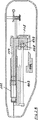
作用物質の注射のため、2チャンバアンプル111を使用する。このようなアンプル(図1B)は、2つのピストン111A,111Bを有し、かくして、まず相互に無関係な2つのチャンバ111C,111Dが生ずる。カニューレ112に向く第1内側チャンバ111Cには、例えば、粉体状のベータフェロンを充填し、第2外側チャンバ111Dには、NaCl溶液を充填する。
A two-
さて、押し棒104を外側ピストン111Bに押圧すると、まず、内側ピストン111Aも摺動される。なぜならば、NaCl溶液が、押し棒の力を内側ピストン111Aに伝達するからである。内側ピストン111Aが、アンプル111のケースのミゾ状隆起の形のオーバフローダクト(ないしバイパスチャンネル)111Eに重なる位置に来る(重畳する、ueberlaufen)と直ちに、上記ピストンは停止し、NaCl溶液は、上記のオーバフローダクト111Eを介して内部チャンバ111Cに流入し、ベータフェロンと混合される。混合後、次いで(穿刺ストローク後)、押し棒104の更なる移動によって注射が行われる。
When the
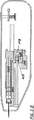
図1Aに、注射装置の実施例の平面図を示し、図1Bに、断面図を示し、図1Cに、面S−Sに沿う他の断面図を示した。 FIG. 1A shows a plan view of an embodiment of the injection device, FIG. 1B shows a cross-sectional view, and FIG. 1C shows another cross-sectional view along the plane SS.
すべての構造部材は、2つの槽状シェル半部からなるハウジング101内にある。この場合、移動構造部材(複数)は、注射装置内に、針の縦軸線に平行に摺動自在に保持されている。構造部材(複数)は、下記の如く、相互に関連づけられている。
All structural members are in a
2チャンバアンプル111は、受け部材103内に保持されている。制御レバー105を後端に樞着した押し棒104は、バネ負荷(付勢)された第1キー102の係止フック102Aに保持されている。受け部材103は、バネ負荷された第2キー116の係止フック116Aに保持されている。
The two-
受け部材103には、スライダ108に支持されたローラ109を介して方向変更され、ハウジング101に固定された引張バネ110に結合された引張ワイヤないしロープ114の端部が作用する。即ち、引張バネ110は、受け部材103に穿刺箇所とは逆方向へ張力を加える。しかしながら、受け部材103は、軸線方向へは摺動できない。なぜならば、受け部材は、係止フック116Aによって第2キー116に係止保持されているからである。
The receiving
ローラ109を介して引張ワイヤないしロープ114を方向変更(反転)することによって、スライダ108に対して穿刺箇所へ向う方向の力が生ずる。しかしながら、スライダ108は、その位置に留まる。なぜならば、スライダ108は、このスライダに注射方向に対し直角に摺動自在に保持され駆動バネ119によって負荷(付勢)された連行駆動部材(Mitnehmer)118を介して押し棒104に当接し、押し棒104は、係止フック102Aによって第1キー102に保持されるからである。
By changing (reversing) the direction of the pulling wire or rope 114 via the
制御レバー105には、第2調節スライダ106を摺動自在に支持した第1調節スライダ107が配してある。第2調節スライダ106は、押し棒104からスライダ108を分離する機能を受持つ。(第1、第2)調節レバー(スライダ)106,107は、以下に更に説明する如く、穿刺箇所および注射容積を調節するための摺動自在に支持された当接部材として構成されている。
The
引張ロッド115に連結された引もどし取手117は、この出発位置の形成に役立つ。引張ロッド115は、引もどしバネ120によって負荷(付勢)される。
A
以下に、推移を説明する。第1キー102を作動(押圧)すると、係止フック102Aが解離され、押し棒104が、解放され、制御レバー105の前縁が受け部材103に当接するまで、穿刺箇所の方向へ移動される。かくして、アンプル111の外側ピストン111Bは、負荷(付勢)され、前方へ移動され、混合ストロークH0を実施する。この混合ストロークは、既述の如く、NaCl溶液をベータフェロンと混合するのに役立つ(図2A,図2B)。ハウジング101の覗き窓を介して、ベータフェロンとNaCl溶液との混合を監視できる。
The transition will be described below. When the
他方、制御レバー105の自由端は、第2調節スライダ107上を摺動し、このスライダ上に載っているので、この制御レバーは、下方への旋回によってこの箇所からそれることはない。即ち、引張バネ110の穿刺箇所へ向う方向の張力は、スライダ108から押し棒104を介して受け部材103に伝達される。しかしながら、受け部材103は、その位置に留まる。なぜならば、この受け部材は、キー116の係止フック116Aによってロックされているからである。
On the other hand, since the free end of the
さて、第2キー116を作動(押圧)すると、係止フック116Aが解離され、受け部材103が解放される。かくして、押し棒104および受け部材103は、引張バネ110の作用によって同時に穿刺箇所の方向へ移動される。針が穿刺され(図3A,3B)、穿刺ストロークH1が実施される(図4A,4B)。
Now, when the
所望の穿刺箇所に達すると、制御レバー105は下方へ旋回できる(図4Aの矢印)。
なぜならば、この制御レバーは、もはや、第1調節スライダ107の跳反表面にもとづき旋回阻止されることはないからである。即ち、押し棒104から受け部材103への力伝達は、もはや、行われず、受け部材103は、その位置に留まり、押し棒104のみが、穿刺箇所へ向かって更に移動し、即ち、医薬の注射が行われ、注射ストロークH2が実施される。
When the desired puncture site is reached, the
This is because the control lever is no longer prevented from turning due to the recoil surface of the
スライダ108に摺動自在に支持された連行駆動部材118が第2調節スライダ106の傾斜面106Aに達すると(図4B)、連行駆動部材118は、下方へ引張され、従って、スライダ108は、押し棒104から解離され、即ち、この時点において、注射が終了する(図5A)。
When the
さて、スライダ108は、(第2)調節スライダ106に当接する。さて、(第2)調節スライダ106は、第1調節スライダ107を介して形状結合(ありつぎ結合)状態でハウジング101に保持されるので、(ハウジング101に固定された)引張バネ110の張力が、ローラ109を介して受け部材103に作用し、かくして、上記受け部材は、引もどされ、かくして、針は、穿刺箇所から引出され(図6A,6B)、引もどしストロークH3が実施される。
Now, the
引張ロッド115に結合(連結)された引もどし取手117を下方へ倒し引張ロッド115を引出すことによって、スライダ108および他のすべての部材は、再び、出発位置に引もどされる(図1A,1B)。(引きもどし取手117を手離せば)引張ロッド115は、再び、引もどしバネ120によって引込まれる。
By pulling down the pulling
今や、アンプルを取出すことができる。 Now you can take out the ampoule.
注射容積および穿刺深さは、下記の如く調節される。 The injection volume and puncture depth are adjusted as follows.
第1調節スライダ107は、ハウジング101に軸線方向へ摺動自在に支持されており、図示の実施例の場合、2つの係止位置(10mmおよび12mm,例えば、10mmに調節される)を有する。これらの係止位置は、穿刺ストロークH1に関連づけられる。なぜならば、制御レバー105が押し棒104を受け部材103から解離するまで(図2A)、調節スライダ107の軸線方向位置が、行程(ストローク)を決定するからである。
The
第1調節スライダ107には、第2調節スライダ106が、同じく軸線方向へ摺動自在に支持されており、例えば、4つの係止位置を有する(1.0;0.75;0.5;0.25,例えば、1.0に調節される)。これらの係止位置は、注射ストロークH2に関連づけられる。なぜならば、押し棒104がスライダ108から解離され(図5A,5B)、針の引もどしが行われるまで、第2調節スライダ106の軸線方向位置が、行程(ストローク)を決定するからである。
The
さて、例えば、穿刺深さを12mmに調節すべき場合、図示の状態に対して、第1調節スライダ107を穿刺箇所の方向へ2mmだけハウジング101の新しい係止位置に摺動させなければならない。第2調節スライダ106は、位置1.0において第1調節スライダ107に係合されているので、この第2調節スライダも、2mmだけ穿刺箇所へ向かって摺動され、即ち、異なる穿刺深さの調節が、注射容積の調節に作用することはない。同じく、注射容積の調節が、穿刺深さに作用することはない。穿刺ストロークH1および注射ストロークH2の調節は、相互に独立である。
For example, when the puncture depth is to be adjusted to 12 mm, the
101 ハウジング
102 第1キー
102A 係止フック
103 受け部材
104 押し棒
105 制御レバー
106 第2調節スライダ
106A 傾斜面
107 第1調節スライダ
108 スライダ
109 ローラ
110 引張バネ
111 アンプル
112 カニューレ
114 引張ワイヤないしロープ(Zugseil)
115 引張ロッド
116 第2キー
116A 係止フック
117 引もどし取手
118 連行駆動部材(Mitnehmer)
119 駆動バネ
120 引もどしバネ
DESCRIPTION OF
115 Pulling
119
Claims (17)
ハウジング(101)内には、2チャンバアンプル(111)を導入、固定できる受け部材(103)が保持されており、
スライダ(108)によって受け部材(103)を摺動でき、受け部材(103)内には、両ピストン(111A,111B)に負荷を加える押し棒(104)が摺動自在に保持されており、
混合ストローク、穿刺ストローク、注射ストロークおよび引もどしストロークを実施するため、受け部材(103)に一端で結合されハウジング(101)に係止された引張バネ(110)に他端で結合され、スライダ(108)に支持されたローラ(109)を介して方向変更される引張ワイヤないしロープ(Zugseil)(114)が設けてあり、
1つの引張バネ(110)の回復力により、最初にローラ(109)を介してスライダ(108)を牽引して混合ストローク、穿刺ストローク、注射ストロークを順に実施し、これらのストロークの終了後はスライダ(108)が当接係止されることにより、引張バネ(110)の回復力がこれらのストロークとは反対方向に受け部材(103)に作用して引もどしストロークを実施するように構成され、
ハウジング(101)と受け部材(103)と押し棒(104)とスライダ(108)との間の自動および/または手動の装置(複数)が複数の要素の解除可能な結合により構成され、一時的な結合により力が伝達されることにより、引張ワイヤないしロープ(114)との上記部材の交互の連結を制御し、かくして、混合ストローク、穿刺ストローク、注射ストロークおよび引もどしストロークの一連の行程を制御すること
を特徴とする注射装置。The injection needle and the inner piston (111A) reach the two-chamber ampoule overflow duct (111E) and stop, then the outer piston (111B) removes the first agent in the rear chamber (111D) for the second action. The structural member (s) that move relative to slide the piston of the two-chamber ampoule (111) to mix the substance until it is fed into the front chamber (111C) that contains the substance and reaches the injection needle, and thus mixed An injection device for receiving and operating a two-chamber ampoule having a piston (s) and an overflow duct .
A receiving member (103) capable of introducing and fixing the two-chamber ampoule (111) is held in the housing (101).
A receiving member (103) can be slid by a slider (108), and a push rod (104) for applying a load to both pistons (111A, 111B) is slidably held in the receiving member (103).
In order to carry out the mixing stroke, the puncture stroke, the injection stroke and the withdrawal stroke, it is connected at one end to a tension spring (110) which is connected to the receiving member (103) and locked to the housing (101), and a slider ( 108) a tensioning wire or rope (114) that is redirected via a roller (109) supported on
First, the slider (108) is pulled through the roller (109) by the recovery force of one tension spring (110), and the mixing stroke, the puncture stroke, and the injection stroke are performed in this order. (108) is configured to abut and lock so that the recovery force of the tension spring (110) acts on the receiving member (103) in the direction opposite to these strokes to perform the return stroke,
An automatic and / or manual device (s) between the housing (101), the receiving member (103), the push rod (104) and the slider (108) is constituted by a releasable coupling of a plurality of elements and is temporarily Force is transmitted by a simple connection to control the alternating connection of the member with the pull wire or rope (114), thus controlling the sequence of mixing stroke, puncture stroke, injection stroke and withdrawal stroke. An injection device characterized by:
Applications Claiming Priority (3)
| Application Number | Priority Date | Filing Date | Title |
|---|---|---|---|
| DE202005014958.6 | 2005-09-22 | ||
| DE202005014958U DE202005014958U1 (en) | 2005-09-22 | 2005-09-22 | Injection unit comprising a seat for a syringe body with two pistons and two chambers and a means for driving the plunger to produce a mixing stroke before an injection stroke |
| PCT/DE2006/001512 WO2007033638A1 (en) | 2005-09-22 | 2006-08-31 | Automatic injection device for two-chamber ampullas |
Publications (2)
| Publication Number | Publication Date |
|---|---|
| JP2009508602A JP2009508602A (en) | 2009-03-05 |
| JP5076109B2 true JP5076109B2 (en) | 2012-11-21 |
Family
ID=35502312
Family Applications (1)
| Application Number | Title | Priority Date | Filing Date |
|---|---|---|---|
| JP2008531522A Expired - Fee Related JP5076109B2 (en) | 2005-09-22 | 2006-08-31 | Two-chamber ampule automatic injection device |
Country Status (12)
| Country | Link |
|---|---|
| US (1) | US7678072B2 (en) |
| EP (1) | EP1931405B1 (en) |
| JP (1) | JP5076109B2 (en) |
| KR (1) | KR101309718B1 (en) |
| CN (1) | CN101267856B (en) |
| BR (1) | BRPI0616307B1 (en) |
| CA (1) | CA2623152C (en) |
| DE (2) | DE202005014958U1 (en) |
| HK (1) | HK1119098A1 (en) |
| MX (1) | MX2008002782A (en) |
| TR (1) | TR201901372T4 (en) |
| WO (1) | WO2007033638A1 (en) |
Families Citing this family (44)
| Publication number | Priority date | Publication date | Assignee | Title |
|---|---|---|---|---|
| US20190357827A1 (en) | 2003-08-01 | 2019-11-28 | Dexcom, Inc. | Analyte sensor |
| US10737028B2 (en) | 2004-11-22 | 2020-08-11 | Kaleo, Inc. | Devices, systems and methods for medicament delivery |
| JP4960252B2 (en) | 2004-11-22 | 2012-06-27 | インテリジェクト,インコーポレイテッド | Device, system and method for drug delivery |
| US11590286B2 (en) | 2004-11-22 | 2023-02-28 | Kaleo, Inc. | Devices, systems and methods for medicament delivery |
| US7947017B2 (en) | 2004-11-22 | 2011-05-24 | Intelliject, Inc. | Devices, systems and methods for medicament delivery |
| US7648483B2 (en) * | 2004-11-22 | 2010-01-19 | Intelliject, Inc. | Devices, systems and methods for medicament delivery |
| ES2396745T3 (en) | 2005-02-01 | 2013-02-25 | Intelliject, Inc. | Devices for medication administration |
| DE602007013723D1 (en) * | 2006-02-09 | 2011-05-19 | Deka Products Lp | SYSTEMS FOR DISPENSING FLUIDS IN PATCH SIZE |
| MY154721A (en) | 2007-06-08 | 2015-07-15 | Bayer Ip Gmbh | Injection device |
| US9452258B2 (en) | 2007-10-09 | 2016-09-27 | Dexcom, Inc. | Integrated insulin delivery system with continuous glucose sensor |
| EP2219710B2 (en) † | 2007-11-12 | 2020-08-05 | Medicom Innovation Partner a/s | Auto injector with automatic needle retraction |
| US8812082B2 (en) * | 2008-10-30 | 2014-08-19 | Acist Medical Systems, Inc. | Automatically supplying a pressurizing unit of a medical injection device with fluid |
| GB0821492D0 (en) | 2008-11-25 | 2008-12-31 | Team Holdings Uk Ltd | Integrated auto-injector cartridge system |
| GB0900930D0 (en) * | 2009-01-20 | 2009-03-04 | Future Injection Technologies Ltd | Injection device |
| DE202009001836U1 (en) * | 2009-02-13 | 2009-05-20 | Dieter Hölzle Technik-Projekte GmbH | Electromechanical injection device |
| DE202009003009U1 (en) | 2009-03-03 | 2009-06-25 | Dieter Hölzle Technik-Projekte GmbH | Injection device with injection volume adjustment |
| MX2011011758A (en) * | 2009-05-07 | 2012-02-28 | Medical Injection Devices Inc | Medicament dispensing device. |
| KR101131577B1 (en) | 2009-07-22 | 2012-03-30 | 방시열 | Mechanical skin resurfacing device |
| DE202010000846U1 (en) * | 2010-01-13 | 2010-04-15 | Dieter Hölzle Technik-Projekte GmbH | Einstechtiefeneinstellung |
| WO2011111046A1 (en) * | 2010-03-10 | 2011-09-15 | White Innovation Ltd. | Injector |
| US8939943B2 (en) | 2011-01-26 | 2015-01-27 | Kaleo, Inc. | Medicament delivery device for administration of opioid antagonists including formulations for naloxone |
| US8627816B2 (en) | 2011-02-28 | 2014-01-14 | Intelliject, Inc. | Medicament delivery device for administration of opioid antagonists including formulations for naloxone |
| US9084849B2 (en) | 2011-01-26 | 2015-07-21 | Kaleo, Inc. | Medicament delivery devices for administration of a medicament within a prefilled syringe |
| GB2490721B (en) | 2011-05-12 | 2017-03-01 | Owen Mumford Ltd | Injection devices |
| US9522235B2 (en) | 2012-05-22 | 2016-12-20 | Kaleo, Inc. | Devices and methods for delivering medicaments from a multi-chamber container |
| DE202014004561U1 (en) | 2014-06-03 | 2014-07-03 | H & B Electronic Gmbh & Co. Kg | injection device |
| US9517307B2 (en) | 2014-07-18 | 2016-12-13 | Kaleo, Inc. | Devices and methods for delivering opioid antagonists including formulations for naloxone |
| IL295010A (en) | 2015-03-10 | 2022-09-01 | Regeneron Pharma | Aseptic piercing system and method |
| US10695495B2 (en) | 2015-03-24 | 2020-06-30 | Kaleo, Inc. | Devices and methods for delivering a lyophilized medicament |
| WO2017004345A1 (en) | 2015-06-30 | 2017-01-05 | Kaleo, Inc. | Auto-injectors for administration of a medicament within a prefilled syringe |
| DK4238496T3 (en) | 2015-12-30 | 2024-02-26 | Dexcom Inc | TRANSCUTANEOUS ANALYTE SENSOR SYSTEMS AND METHODS |
| US10780226B2 (en) | 2016-03-16 | 2020-09-22 | Eli Lilly And Company | Trigger assembly for automatic medication injection device |
| US10864326B2 (en) | 2016-03-16 | 2020-12-15 | Eli Lilly And Company | Medication injection device with automatic needle retraction following injection |
| GB2549750A (en) * | 2016-04-27 | 2017-11-01 | Owen Mumford Ltd | Medicament delivery device |
| JP7014797B2 (en) | 2016-12-23 | 2022-02-01 | カレオ,インコーポレイテッド | Drug delivery devices and methods for delivering drugs to babies and children |
| BR112019020705A2 (en) | 2017-05-05 | 2020-05-12 | Regeneron Pharmaceuticals, Inc. | AUTOINJECTOR |
| KR20200067124A (en) | 2017-06-23 | 2020-06-11 | 덱스콤, 인크. | Transdermal analysis sensor, applicator for this, and associated method |
| US11331022B2 (en) | 2017-10-24 | 2022-05-17 | Dexcom, Inc. | Pre-connected analyte sensors |
| US20190120785A1 (en) | 2017-10-24 | 2019-04-25 | Dexcom, Inc. | Pre-connected analyte sensors |
| CN108324289B (en) * | 2018-04-17 | 2020-12-11 | 青岛市市立医院 | Blood collection system that medical science inspection was used |
| EP4009936A4 (en) | 2019-08-09 | 2023-08-09 | Kaleo, Inc. | Devices and methods for delivery of substances within a prefilled syringe |
| DE102020133827A1 (en) | 2020-12-16 | 2022-06-23 | IDTM GmbH | injector and injector system |
| USD1007676S1 (en) | 2021-11-16 | 2023-12-12 | Regeneron Pharmaceuticals, Inc. | Wearable autoinjector |
| WO2024016140A1 (en) * | 2022-07-19 | 2024-01-25 | 嘉兴森迈医疗科技有限公司 | Automatic injection apparatus |
Family Cites Families (10)
| Publication number | Priority date | Publication date | Assignee | Title |
|---|---|---|---|---|
| FR82914E (en) * | 1962-11-16 | 1964-05-08 | Automatic gun for intramuscular puncture | |
| FR2616221A1 (en) * | 1987-06-02 | 1988-12-09 | Archambeaud Philippe | Device for automatic injection of products and in particular medicinal products contained in a syringe or other injection system |
| FR2815543B1 (en) * | 2000-10-19 | 2003-10-24 | Sedat | SELF-INJECTION SYRINGE OF AN EXTEMPORANEOUS MIXTURE |
| US6387078B1 (en) * | 2000-12-21 | 2002-05-14 | Gillespie, Iii Richard D. | Automatic mixing and injecting apparatus |
| US20030105430A1 (en) * | 2001-11-30 | 2003-06-05 | Elan Pharma International Limited Wil House | Automatic injector |
| GB0204640D0 (en) * | 2002-02-27 | 2002-04-10 | Torsana Diabetes Diagnostics A | Injection apparatus |
| JP4039876B2 (en) * | 2002-03-27 | 2008-01-30 | テルモ株式会社 | Chemical injection device |
| JP4598520B2 (en) * | 2002-07-02 | 2010-12-15 | パナソニック株式会社 | Medical automatic administration device |
| US20070100288A1 (en) * | 2003-06-05 | 2007-05-03 | University Of Florida Research Foundation, Inc. | Auto-injection devices and methods for intramuscular administration of medications |
| DE20311996U1 (en) * | 2003-08-01 | 2003-10-16 | Hoelzle Dieter Tech Projekte | injection device |
-
2005
- 2005-09-22 DE DE202005014958U patent/DE202005014958U1/en not_active Expired - Lifetime
-
2006
- 2006-08-31 KR KR1020087006734A patent/KR101309718B1/en active IP Right Grant
- 2006-08-31 WO PCT/DE2006/001512 patent/WO2007033638A1/en active Application Filing
- 2006-08-31 BR BRPI0616307-6A patent/BRPI0616307B1/en not_active IP Right Cessation
- 2006-08-31 DE DE112006003252T patent/DE112006003252A5/en not_active Withdrawn
- 2006-08-31 MX MX2008002782A patent/MX2008002782A/en active IP Right Grant
- 2006-08-31 CA CA2623152A patent/CA2623152C/en not_active Expired - Fee Related
- 2006-08-31 TR TR2019/01372T patent/TR201901372T4/en unknown
- 2006-08-31 EP EP06791326.9A patent/EP1931405B1/en active Active
- 2006-08-31 JP JP2008531522A patent/JP5076109B2/en not_active Expired - Fee Related
- 2006-08-31 US US12/067,766 patent/US7678072B2/en active Active
- 2006-08-31 CN CN2006800342676A patent/CN101267856B/en not_active Expired - Fee Related
-
2008
- 2008-12-04 HK HK08113242.1A patent/HK1119098A1/en not_active IP Right Cessation
Also Published As
| Publication number | Publication date |
|---|---|
| WO2007033638A1 (en) | 2007-03-29 |
| EP1931405A1 (en) | 2008-06-18 |
| BRPI0616307A2 (en) | 2011-06-14 |
| JP2009508602A (en) | 2009-03-05 |
| US20080188798A1 (en) | 2008-08-07 |
| TR201901372T4 (en) | 2019-02-21 |
| EP1931405B1 (en) | 2018-11-14 |
| DE112006003252A5 (en) | 2008-09-04 |
| CN101267856A (en) | 2008-09-17 |
| CA2623152C (en) | 2015-03-17 |
| KR101309718B1 (en) | 2013-09-17 |
| CN101267856B (en) | 2011-04-06 |
| US7678072B2 (en) | 2010-03-16 |
| CA2623152A1 (en) | 2007-03-29 |
| BRPI0616307B1 (en) | 2018-06-26 |
| HK1119098A1 (en) | 2009-02-27 |
| DE202005014958U1 (en) | 2005-12-08 |
| KR20080065592A (en) | 2008-07-14 |
| MX2008002782A (en) | 2008-09-15 |
Similar Documents
| Publication | Publication Date | Title |
|---|---|---|
| JP5076109B2 (en) | Two-chamber ampule automatic injection device | |
| US10118002B2 (en) | Devices for injecting a substance and methods therefor | |
| US6599272B1 (en) | Injection device and method for its operation | |
| RU2470678C2 (en) | Injection device | |
| AU675534B2 (en) | Multiple medication injection apparatus and method | |
| EP3544656A1 (en) | Device for dispensing a substance | |
| CZ20023823A3 (en) | Medicinal assembly | |
| JP2020508134A (en) | Automatic fluid injection device | |
| JP7431153B2 (en) | Assisted injection device for injecting compositions contained within medical containers with reduced effort | |
| JP2012502765A (en) | Medical syringe with dose setting after automatic reconfiguration and automatic plunger drive | |
| JP4344344B2 (en) | Dosing device | |
| CN100518842C (en) | Pressure and volume controlled hybrid type needle cylinder device |
Legal Events
| Date | Code | Title | Description |
|---|---|---|---|
| A621 | Written request for application examination |
Free format text: JAPANESE INTERMEDIATE CODE: A621 Effective date: 20090724 |
|
| A977 | Report on retrieval |
Free format text: JAPANESE INTERMEDIATE CODE: A971007 Effective date: 20110831 |
|
| A131 | Notification of reasons for refusal |
Free format text: JAPANESE INTERMEDIATE CODE: A131 Effective date: 20110906 |
|
| A601 | Written request for extension of time |
Free format text: JAPANESE INTERMEDIATE CODE: A601 Effective date: 20111206 |
|
| A602 | Written permission of extension of time |
Free format text: JAPANESE INTERMEDIATE CODE: A602 Effective date: 20111213 |
|
| A601 | Written request for extension of time |
Free format text: JAPANESE INTERMEDIATE CODE: A601 Effective date: 20111226 |
|
| A602 | Written permission of extension of time |
Free format text: JAPANESE INTERMEDIATE CODE: A602 Effective date: 20120106 |
|
| A521 | Request for written amendment filed |
Free format text: JAPANESE INTERMEDIATE CODE: A523 Effective date: 20120118 |
|
| TRDD | Decision of grant or rejection written | ||
| A01 | Written decision to grant a patent or to grant a registration (utility model) |
Free format text: JAPANESE INTERMEDIATE CODE: A01 Effective date: 20120710 |
|
| A01 | Written decision to grant a patent or to grant a registration (utility model) |
Free format text: JAPANESE INTERMEDIATE CODE: A01 |
|
| A61 | First payment of annual fees (during grant procedure) |
Free format text: JAPANESE INTERMEDIATE CODE: A61 Effective date: 20120726 |
|
| FPAY | Renewal fee payment (event date is renewal date of database) |
Free format text: PAYMENT UNTIL: 20150907 Year of fee payment: 3 |
|
| R150 | Certificate of patent or registration of utility model |
Ref document number: 5076109 Country of ref document: JP Free format text: JAPANESE INTERMEDIATE CODE: R150 Free format text: JAPANESE INTERMEDIATE CODE: R150 |
|
| S111 | Request for change of ownership or part of ownership |
Free format text: JAPANESE INTERMEDIATE CODE: R313113 |
|
| R350 | Written notification of registration of transfer |
Free format text: JAPANESE INTERMEDIATE CODE: R350 |
|
| R250 | Receipt of annual fees |
Free format text: JAPANESE INTERMEDIATE CODE: R250 |
|
| R250 | Receipt of annual fees |
Free format text: JAPANESE INTERMEDIATE CODE: R250 |
|
| R250 | Receipt of annual fees |
Free format text: JAPANESE INTERMEDIATE CODE: R250 |
|
| R250 | Receipt of annual fees |
Free format text: JAPANESE INTERMEDIATE CODE: R250 |
|
| LAPS | Cancellation because of no payment of annual fees |