JP5060485B2 - A method and system for verifying the availability and freshness of replicated data. - Google Patents
A method and system for verifying the availability and freshness of replicated data. Download PDFInfo
- Publication number
- JP5060485B2 JP5060485B2 JP2008533573A JP2008533573A JP5060485B2 JP 5060485 B2 JP5060485 B2 JP 5060485B2 JP 2008533573 A JP2008533573 A JP 2008533573A JP 2008533573 A JP2008533573 A JP 2008533573A JP 5060485 B2 JP5060485 B2 JP 5060485B2
- Authority
- JP
- Japan
- Prior art keywords
- volume
- cabo
- access path
- network
- replicon
- Prior art date
- Legal status (The legal status is an assumption and is not a legal conclusion. Google has not performed a legal analysis and makes no representation as to the accuracy of the status listed.)
- Active
Links
Images


Classifications
-
- G—PHYSICS
- G06—COMPUTING; CALCULATING OR COUNTING
- G06F—ELECTRIC DIGITAL DATA PROCESSING
- G06F16/00—Information retrieval; Database structures therefor; File system structures therefor
- G06F16/20—Information retrieval; Database structures therefor; File system structures therefor of structured data, e.g. relational data
- G06F16/23—Updating
- G06F16/2308—Concurrency control
-
- G—PHYSICS
- G06—COMPUTING; CALCULATING OR COUNTING
- G06F—ELECTRIC DIGITAL DATA PROCESSING
- G06F11/00—Error detection; Error correction; Monitoring
- G06F11/07—Responding to the occurrence of a fault, e.g. fault tolerance
- G06F11/16—Error detection or correction of the data by redundancy in hardware
- G06F11/20—Error detection or correction of the data by redundancy in hardware using active fault-masking, e.g. by switching out faulty elements or by switching in spare elements
- G06F11/2053—Error detection or correction of the data by redundancy in hardware using active fault-masking, e.g. by switching out faulty elements or by switching in spare elements where persistent mass storage functionality or persistent mass storage control functionality is redundant
- G06F11/2094—Redundant storage or storage space
-
- G—PHYSICS
- G06—COMPUTING; CALCULATING OR COUNTING
- G06F—ELECTRIC DIGITAL DATA PROCESSING
- G06F16/00—Information retrieval; Database structures therefor; File system structures therefor
- G06F16/20—Information retrieval; Database structures therefor; File system structures therefor of structured data, e.g. relational data
- G06F16/27—Replication, distribution or synchronisation of data between databases or within a distributed database system; Distributed database system architectures therefor
- G06F16/273—Asynchronous replication or reconciliation
-
- G—PHYSICS
- G06—COMPUTING; CALCULATING OR COUNTING
- G06F—ELECTRIC DIGITAL DATA PROCESSING
- G06F16/00—Information retrieval; Database structures therefor; File system structures therefor
- G06F16/20—Information retrieval; Database structures therefor; File system structures therefor of structured data, e.g. relational data
- G06F16/27—Replication, distribution or synchronisation of data between databases or within a distributed database system; Distributed database system architectures therefor
- G06F16/275—Synchronous replication
-
- H—ELECTRICITY
- H04—ELECTRIC COMMUNICATION TECHNIQUE
- H04L—TRANSMISSION OF DIGITAL INFORMATION, e.g. TELEGRAPHIC COMMUNICATION
- H04L67/00—Network arrangements or protocols for supporting network services or applications
- H04L67/01—Protocols
- H04L67/10—Protocols in which an application is distributed across nodes in the network
- H04L67/1095—Replication or mirroring of data, e.g. scheduling or transport for data synchronisation between network nodes
-
- G—PHYSICS
- G06—COMPUTING; CALCULATING OR COUNTING
- G06F—ELECTRIC DIGITAL DATA PROCESSING
- G06F11/00—Error detection; Error correction; Monitoring
- G06F11/07—Responding to the occurrence of a fault, e.g. fault tolerance
- G06F11/16—Error detection or correction of the data by redundancy in hardware
- G06F11/20—Error detection or correction of the data by redundancy in hardware using active fault-masking, e.g. by switching out faulty elements or by switching in spare elements
- G06F11/2053—Error detection or correction of the data by redundancy in hardware using active fault-masking, e.g. by switching out faulty elements or by switching in spare elements where persistent mass storage functionality or persistent mass storage control functionality is redundant
- G06F11/2056—Error detection or correction of the data by redundancy in hardware using active fault-masking, e.g. by switching out faulty elements or by switching in spare elements where persistent mass storage functionality or persistent mass storage control functionality is redundant by mirroring
- G06F11/2058—Error detection or correction of the data by redundancy in hardware using active fault-masking, e.g. by switching out faulty elements or by switching in spare elements where persistent mass storage functionality or persistent mass storage control functionality is redundant by mirroring using more than 2 mirrored copies
-
- G—PHYSICS
- G06—COMPUTING; CALCULATING OR COUNTING
- G06F—ELECTRIC DIGITAL DATA PROCESSING
- G06F11/00—Error detection; Error correction; Monitoring
- G06F11/07—Responding to the occurrence of a fault, e.g. fault tolerance
- G06F11/16—Error detection or correction of the data by redundancy in hardware
- G06F11/20—Error detection or correction of the data by redundancy in hardware using active fault-masking, e.g. by switching out faulty elements or by switching in spare elements
- G06F11/2053—Error detection or correction of the data by redundancy in hardware using active fault-masking, e.g. by switching out faulty elements or by switching in spare elements where persistent mass storage functionality or persistent mass storage control functionality is redundant
- G06F11/2056—Error detection or correction of the data by redundancy in hardware using active fault-masking, e.g. by switching out faulty elements or by switching in spare elements where persistent mass storage functionality or persistent mass storage control functionality is redundant by mirroring
- G06F11/2069—Management of state, configuration or failover
-
- G—PHYSICS
- G06—COMPUTING; CALCULATING OR COUNTING
- G06F—ELECTRIC DIGITAL DATA PROCESSING
- G06F11/00—Error detection; Error correction; Monitoring
- G06F11/07—Responding to the occurrence of a fault, e.g. fault tolerance
- G06F11/16—Error detection or correction of the data by redundancy in hardware
- G06F11/20—Error detection or correction of the data by redundancy in hardware using active fault-masking, e.g. by switching out faulty elements or by switching in spare elements
- G06F11/2053—Error detection or correction of the data by redundancy in hardware using active fault-masking, e.g. by switching out faulty elements or by switching in spare elements where persistent mass storage functionality or persistent mass storage control functionality is redundant
- G06F11/2056—Error detection or correction of the data by redundancy in hardware using active fault-masking, e.g. by switching out faulty elements or by switching in spare elements where persistent mass storage functionality or persistent mass storage control functionality is redundant by mirroring
- G06F11/2071—Error detection or correction of the data by redundancy in hardware using active fault-masking, e.g. by switching out faulty elements or by switching in spare elements where persistent mass storage functionality or persistent mass storage control functionality is redundant by mirroring using a plurality of controllers
Description
本件出願は、ここに引用することによりその全てを本明細書に含むものとする2005年9月27日付で提出した米国仮特許出願番号第60/720,977号の利益を主張するものである。
本発明は、ネットワーク環境内で複製(以下、レプリケーションとも称する)されたデータの可用性及び最新性、即ち、実態を判定及び検証するための方法及びシステムに関する。
This application claims the benefit of US Provisional Patent Application No. 60 / 720,977, filed Sep. 27, 2005, which is hereby incorporated by reference in its entirety.
The present invention relates to a method and system for determining and verifying the availability and freshness, ie, the actual state, of data replicated in a network environment (hereinafter also referred to as replication).
データレプリケーションはデータの可用性を高めるために通常用いられる手法である。データセットを多重に複製して別々の場所に保存すれば、例え幾つかのコンポーネント障害が発生する又はデータセットの幾つかが破損した場合でも、クライアントアプリケーション用の複製データ(以下、レプリカデータとも称する)をずっと入手し易くなる。
コンピューティングシステムには、データをコピーし、多数のレプリカデータを管理するための数多くの手法がある。複製手法は2つの主要カテゴリー、即ち、同期複製法と非同期複製法とに分類される。同期複製法ではソースデータセットとレプリカデータとは連続的に完全同期されるのでトランザクションが高度に保証され、またソースデータセットのアップデートは一貫して且つ直ちに全部の同期レプリカデータに反映される。然し乍ら同期複製法は、それがコンピューティングリソースに課す諸経費上、同法を実現するための費用が法外に高額になったり、全く実現不能になる場合(例えば、環境内の幾つかのコンポーネントの一時的破損による)もある。
他方、非同期複製法ではデータは定期的に複製されるだけなので、各レプリカデータ間の時間整合性の厳密度はずっと低くなり、レプリカデータは現在のデータソースではなくむしろ、ある程度前のデータソース状態を表すものとなり得る。参照ポイントがどの程度前かにもよるが、ある例外的状況(例えば、破局的障害からの復旧)下のあるクライアントアプリケーションにとってはそうした不整合は尚、許容し得るものである。非同期複製法は、コンピューティングリソースに課す諸経費がずっと低いので、障害復旧(DR)用にアプリケーションデータのリモートコピーを維持する等の多くの環境で一般に使用されている。
Data replication is a commonly used technique for increasing data availability. If the data set is duplicated and stored in different locations, even if some component failure occurs or some of the data set is damaged, the client application's replicated data (hereinafter also referred to as replica data) ) Is much easier to obtain.
There are numerous approaches to computing systems for copying data and managing a large number of replica data. Replication methods fall into two main categories: synchronous replication methods and asynchronous replication methods. In the synchronous replication method, since the source data set and the replica data are continuously and completely synchronized, the transaction is highly guaranteed, and the update of the source data set is consistently and immediately reflected in all the synchronous replica data. However, synchronous replication can be expensive when it comes to computing resources, and it can be prohibitively expensive or completely unfeasible (eg, some components in the environment). Due to temporary damage.
On the other hand, since asynchronous replication only replicates data on a regular basis, the time consistency between replica data is much lower, and the replica data is not the current data source, but rather the data source state some time ago. Can be represented. Depending on how long the reference point is, such inconsistencies are still acceptable for certain client applications under certain exceptional circumstances (eg, recovery from catastrophic failure). Asynchronous replication methods are commonly used in many environments, such as maintaining a remote copy of application data for disaster recovery (DR), since the overhead on computing resources is much lower.
然し乍ら、データセット及びその複製をアプリケーション条件と確実に一致させ続けるのは数多くの理由から困難な課題となっており、そうした理由には、あるアプリケーションのレプリカデータの最新性に関する最低条件は別のアプリケーションのそれとは異なり得る(つまり、コストを取るか最新性を取るかについて相違がある)こと、代表的な環境では同時に実行可能な多数のデータコピー機が存在し得ること、コピー動作がオリジナルのデータセットではなくむしろレプリカデータセット(完全に最新では無い可能性がある)に基づくものであり得るので依存関係連鎖が生じること、個々のコピー動作が完全に失敗し、例えば、ネットワーク又はコポーネント設定上の問題が生じ、リモートサイトに置いたレプリカデータをホスト側で利用できなくなること、等がある。
結局、アプリケーションは必要時にリモートサイトの十分最新のレプリカデータを利用することができない可能性があるが、現段階ではそうした欠陥はアプリケーションがレプリカデータを実際に必要とするまで分からない。現在の複製手法は、多数のレプリカデータの最新性や可用性を連続的にEnd−to−End検証することではなく、個々のコピーメカニズムの実用精度に関心が向けられている。
However, ensuring that a dataset and its replicas remain consistent with application conditions has been challenging for a number of reasons, because the minimum requirement for the freshness of one application's replica data is another application. (That is, there is a difference in cost or up-to-date), there can be many data copiers that can run simultaneously in a typical environment, and the copy operation is the original data Can be based on replica data sets (which may not be completely up-to-date) rather than sets, resulting in dependency chains, individual copy operations failing completely, eg on network or component settings If a problem occurs and the replica data placed at the remote site is Not be able to use, and the like.
Eventually, the application may not be able to make use of sufficiently up-to-date replica data at the remote site when needed, but at this stage such defects are not known until the application actually needs the replica data. Current replication techniques are not concerned with end-to-end verification of the continuousness and availability of a large number of replica data, but are concerned with the practical accuracy of individual copy mechanisms.
ネットワーク上のレプリカデータセットがアップリケーションの最新性及び可用性に関する指定条件と一致しているかを連続的に検証し、また、不一致を特定し、望ましからざる結果が生じる前に正しい取り扱いがなされるようにユーザーにこの不一致を知らせるシステム及び方法を提供することである。 Continuously verify that replica datasets on the network meet specified requirements for application up-to-date and availability, identify discrepancies, and handle them correctly before undesired results occur And providing a system and method to inform the user of this discrepancy.
本発明によれば、ネットワーク上のレプリカデータセットがレプリカデータポリシーと合致していることを連続的に検証するシステム及び方法が提供される。
本発明の1様相によれば、ネットワーク上のネットワーク機器に置いたレプリカデータを検証するための方法であって、ネットワーク上でデータを複製するためのレプリカデータポリシーを定義する段階と、各ネットワーク機器間又はネットワーク機器上で実行される各アプリケーション間のアクセス経路を監視すること、ネットワーク上でのデータ複製動作を監視すること、レプリカデータの最新性と可用性とをレプリカデータポリシーの条件と比較してレプリカデータポリシーとの不一致を識別すること、を含む方法が提供される。
In accordance with the present invention, a system and method are provided for continuously verifying that a replica data set on a network is consistent with a replica data policy.
According to one aspect of the present invention, there is provided a method for verifying replica data placed on a network device on a network, the step of defining a replica data policy for replicating data on the network, and each network device Monitoring access paths between applications running on the network or on network devices, monitoring data replication activity on the network, comparing replica data up-to-date and availability with the conditions of the replica data policy Identifying a mismatch with the replica data policy is provided.
本発明の他の様相によれば、ネットワーク上のネットワーク機器に置いたレプリカデータを検証するためのレプリカデータ検証マネージャであって、ネットワーク上のレプリカデータ用のレプリカデータポリシーを記憶したポリシーエンジンと、各ネットワーク機器又はネットワーク機器上で実行される各アプリケーション間のアクセス経路を監視する検証エンジンと、を含むレプリカデータ検証マネージャが提供される。検証エンジンはネットワーク上での複製動作をも監視し、レプリカデータの最新性と可用性とをレプリカデータポリシーの条件と比較してレプリカデータポリシーとの不一致を識別する。レプリカデータ検証マネージャは、レプリカデータを検証できない時に違反報告を提供する通知エンジンをも含む。 According to another aspect of the present invention, a replica data verification manager for verifying replica data placed on a network device on a network, the policy engine storing a replica data policy for replica data on the network; A replica data verification manager is provided that includes each network device or a verification engine that monitors an access path between each application running on the network device. The verification engine also monitors replication operations on the network and compares replica data up-to-date and availability with replica data policy conditions to identify inconsistencies with the replica data policy. The replica data verification manager also includes a notification engine that provides a violation report when replica data cannot be verified.
本発明のある実施例には以下に説明する特徴部分の1つ以上が含まれ得る。レプリカデータポリシーは、ホスト又はアプリケーションとレプリカデータとの間のアクセス経路、及び又はネットワーク上のレプリカデータ数、レプリカデータ位置、各レプリカデータ間の1つ以上のアクセス経路、及び又は各レプリカデータ位置での相当するレプリカデータの最長有効時間(maximum−age)を規定し得る。データ複製動作には、同期、分割、コピー開始、コピー完了、ソースデータボリューム、ターゲットデータボリューム、レプリケーション時間、の少なくとも1つを監視することが含まれ得る。各レプリカデータは、ソースデータセットネーム、コピー状態、タイムスタンプの少なくとも1つを含み得るタグと関連付けされ得る。レプリカデータのタグはコピー機イベントに応答してアップデートされ得る。 Certain embodiments of the invention may include one or more of the features described below. The replica data policy is based on the access path between the host or application and the replica data, and / or the number of replica data on the network, the replica data position, one or more access paths between each replica data, and / or each replica data position. Maximum-age of the corresponding replica data can be defined. The data replication operation may include monitoring at least one of synchronization, division, copy start, copy completion, source data volume, target data volume, and replication time. Each replica data may be associated with a tag that may include at least one of a source data set name, a copy status, and a time stamp. The replica data tag may be updated in response to a copier event.
アクセス経路属性には、冗長性及び又は中間コンポーネント数及び又はパフォーマンス及び又はセキュリティ及び又はインターオペラビリティ、共有性又はキャパシティが含まれ得る。不一致は、最新性違反及び又はアクセス経路欠失及び又は不正アクセス経路、及び又は経路属性違反、によって識別され得る。本発明の別の実施例では、レプリケーションリポートには、アプリケーションのプロパティ、レプリケーション違反及びその修正時間、データ保管期間におけるレプリケーションリソース利用、又はそれらの組み合わせ、が含まれ得る。 Access path attributes may include redundancy and / or number of intermediate components and / or performance and / or security and / or interoperability, shareability or capacity. Inconsistencies may be identified by a freshness violation and / or access path deletion and / or unauthorized access path, and / or path attribute violation. In another embodiment of the present invention, the replication report may include application properties, replication violations and their modification time, replication resource utilization during the data storage period, or a combination thereof.
ネットワークのレプリカデータセットがアプリケーションの最新性及び可用性に関する規定条件と一致しているかを連続的に検証し、不一致を特定し、望ましからざる結果が生じる前に正しい取り扱いがなされるようにユーザーにこの不一致を知らせるシステム及び方法が提供される。 Continuously verify that network replica datasets are consistent with application up-to-date and availability requirements, identify discrepancies, and ensure that users are handled correctly before undesired results occur Systems and methods for signaling this discrepancy are provided.
本発明に関し、レプリカデータ環境の各コンポーネンツを以下の用語を用いて分類する。
各用語は以下のように定義する。
“ホストコンポーネント”とは、アプリケーションソフトウェアプログラムがある有益な目的を達成するために実行され得るプラットフォームを言う。各ホストコンポーネントでは任意の時点に1つ以上のアプリケーションが実行され得、各アプリケーションは1つ以上のホストコンポーネント(以下、単にホストとも称する)上で実行され得る。また各ホストはホストリソースへのアクセスや外部コンポーネントへのアクセスを制御する制御プログラムを含み得る。
In connection with the present invention, each component of the replica data environment is classified using the following terms.
Each term is defined as follows.
A “host component” refers to a platform on which an application software program can be executed to achieve a useful purpose. Each host component may execute one or more applications at any given time, and each application may execute on one or more host components (hereinafter also simply referred to as hosts). Each host can also include a control program that controls access to host resources and access to external components.
“ストレージコンポーネント”又は“ストレージデバイス”とは、データを読み書きできるプラットフォームを言う。各ストレージデバイスは、各々が1つ以上のビットを記憶できる複数のアドレスを持つメモリーサブコンポーネントを収納し、データが、ボリュームとして参照される単位でストレージデバイスに関して読み書きされる。1つのボリュームはビット数で表す任意量のデータを含み得、各ボリュームは、特定ストレージデバイスの特定開始アドレスを付けてストレージデバイスに記憶させる。また、各ストレージデバイスにはメモリーサブコンポーネント内のデータへのアクセスを制御するコントローラーサブコンポーネントも格納される。 “Storage component” or “storage device” refers to a platform that can read and write data. Each storage device contains a memory subcomponent having a plurality of addresses each capable of storing one or more bits, and data is read from and written to the storage device in units referred to as volumes. One volume may contain an arbitrary amount of data expressed in number of bits, and each volume is stored in a storage device with a specific start address of a specific storage device. Further, the controller subcomponents for each storage device to control access to data in memory subcomponent also stored.
“ネットワークコンポーネント”とは、データをそこを介して転送し得る、また任意のソースコンポーネントから任意のターゲットコンポーネントに経由させ得るプラットフォームを言う。各ネットワークコンポーネントは、ソース、宛先及びステータス状態、に基づいてデータフローを制御することができる。
説明した各コンポーネントは、関連するユニーク識別子(名前)を持っている他、データのやり取りを可能にする1つ以上のポートをも有する他に、コンポーネントの現在の“制御構成”を表すローカル状態をも有し得る。この現在の“制御構成”では、ソース及びターゲットの各コンポーネントに基づいてどのデータフローを有効化させるべきかといった特定の情報フロー特性が定義される。
"Network Components" means, data may transferred therethrough and also refers to a platform capable of over an arbitrary target component from any source component. Each network component can control the data flow based on the source, destination and status status.
Each described component has an associated unique identifier (name), one or more ports that allow data to be exchanged, and a local state that represents the current “control configuration” of the component. May also have. This current “control configuration” defines specific information flow characteristics such as which data flow should be enabled based on the source and target components.
一方のコンポーネントから他方のコンポーネントにデータを流し得る“コミュニケーションリンク”を使用して、異なるコンポーネント同士を相互に連結することができ、そうしたコミュニケーションリンクは、1つのサイト位置又はリモート位置で極めて接近して位置付けた各コンポーネントを連結させ得る。あるコミュニケーションチャンネル例では、ケーブル、ポイント間連結部、ローカルエリアネットワーク、ワイドエリアネットワークその他が含まれ得る。
“アクセス経路”とは、コミュニケーションリンクが接続性を持っており、各中間コンポーネントのみならずエンドポイント自体が当該エンドポイント同士間でデータを流せるような構成を持つ場合に、2つのエンドポイント(コンポーネント、データセット等)間に存在するものを言う。
Different components can be interconnected using “communication links” that can flow data from one component to the other, and such communication links can be in close proximity at one site location or at a remote location. Each positioned component can be connected. Some example communication channels may include cables, point-to-point connections, local area networks, wide area networks, and so on.
“Access path” means that two communication endpoints (components) are used when the communication link has connectivity, and not only each intermediate component but also the endpoint itself has a configuration that allows data to flow between the endpoints. , Data sets, etc.).
“環境構成イベント”とは、環境内で生じ得るものであって、異なるクラス、中でも、コンポーネント構成の変化、コンポーネントの追加及び削除、コンポーネントの故障と復帰、データの送受信、データボリュームの読み書き及びその他、を含む異なるクラスに分類され得るものを言う。
“アプリケーション”とは、ホスト上で実行され、新規の“データボリューム”を発生し得、発生したデータボリュームをストレージデバイスに記憶させるべく送信するのみならず、ストレージデバイス上に記憶させた既存のデータボリュームをアップデート又は読み込むものを言う。
“Environmental configuration events” can occur in the environment and are in different classes, especially component configuration changes, component additions and deletions, component failures and recovery, data transmission / reception, data volume read / write and others , Which can be classified into different classes.
An “application” can be executed on the host to generate a new “data volume” and not only send the generated data volume to be stored on the storage device, but also the existing data stored on the storage device. Say something that updates or reads a volume.
“データコピー機”とは、プログラムであって、ある時点にストレージデバイスからデータボリュームを読み取り、読み取ったデータボリュームの同一コピーを同じストレージデバイスの別の位置(アドレス)又は別のストレージデバイスに書き込むものを言う。あるデータコピー機は任意のコンポーネント(ホストコンポーネント、ストレージコンポーネント)上で実行され得る。アプリケーションによりアップデートされた初期ソースボリュームはソースボリュームとして参照され、コピー機から発生する任意のボリュームはレプリカボリュームとして参照される。 “Data copy machine” is a program that reads a data volume from a storage device at a certain point in time and writes the same copy of the read data volume to another location (address) of the same storage device or another storage device Say. A certain data copier can be executed on any component (host component, storage component). The initial source volume updated by the application is referred to as a source volume, and an arbitrary volume generated from the copy machine is referred to as a replica volume.
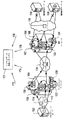
図1には、レプリカデータ環境の1環境例が示され、3つのホストコンポーネント102、108、110と、多数のネットワークコンポーネント、例えば、ストレージエリアネットワーク内のスィッチ又はルーター112、114、116と、ワイドエリアネットワーク内のネットワークコンポーネント118と、2つのストレージコンポーネント104及び106と、幾つかのデータボリューム及びその複製と、を含んでいる。例えばソースボリュームは128、そのローカルレプリカは130であり、132はソースボリューム128のリモートレプリカであり、134はリモートレプリカ132のローカルレプリカ、つまりソースボリューム128のリモートコピーである。各レプリカのためのコピー動作は異なる時点に別個に実施される。ホストコンポーネント102、スィッチ又はルーター114、ソースボリューム128、ローカルレプリカ130、ネットワークコンポーネント118、リモートレプリカ132、ローカルレプリカ134、ホストコンポーネント108、のシーケンス的構成は、全てのローカルコンポーネントが障害復旧(DR)アクセス経路に沿ってデータを転送させ得るべく正しく構成されていることを条件として、障害復旧(DR)アクセス経路の一例である。
FIG. 1 shows an example environment of a replica data environment, with three
ネットワークには、矢印172、174、176、178で示すようにレプリカデータ検証マネージャ101を連結する。レプリカデータ検証マネージャ101は、以下に説明するプロセスを実行し、規定のアプリケーションデータ複製ポリシーに従い、全てのレプリカデータの最新性と可用性とを検証する。
図2には、レプリカデータ検証プロセスのハイレベルでのプロセスデータフロー200を示す。プロセスデータフロー200は、ターゲット環境(コンポーネント、リンク、データコピー機等)を先ず発見するステップ202から開始される。
The network connects the replica
FIG. 2 shows a
ステップ204ではレプリカデータアプリケーションポリシーを定義する。レプリカデータアプリケーションポリシーは、各データボリューム用に、当該データボリュームへのアプリケーションアクセス経路(及び属性)と、当該ボリュームのレプリカ間のアクセス経路と、属性と、各レプリカから別のホストへのアクセス経路と、異なる場所(目標復旧時点(RPO)としても参照される)で各レプリカに要求される最低限の最新性(又は許容できる最大有効時間)条件、を定義する。
ステップ206では環境内での、各レプリカの最新性又は可用性に悪影響を及ぼすイベントについての情報が入手される。例えば、レプリカ130からレプリカ132(図1)までのコピー動作が、レプリカ132の最新状態判定に関わる時間Tに成功裡に終了したことを示す情報が入手され得る。レプリカ134の可用性判定に関わる、ホストコンポーネント108とレプリカ134との間のリンク切れに関する情報が入手され得る。
ステップ208では、各ボリューム及びレプリカの最新性及び可用性の状態(ステータス)に関するイベント情報を引き出すための分析を実行する。
In
In
In
ステップ210では、ステップ208で得た分析結果をポシリーの規定の最新性及び可用性条件と比較し、ステップ212で違反が検出されると当該違反が報告される。そうした違反は状態又は最新性のレベルに関わり得るものであり、例えば、遠隔地に位置付けた、ソースボリューム128の全レプリカの現時点での最新性は、最新性及び可用性条件に規定する最低限の最新性よりも劣る。またそうした違反は可用性にも関わり得るものであり、例えば、リモートホストコンポーネントが、要求されてもソースボリューム128のリモートレプリカを現在利用できないといった場合である。
In
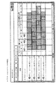
図3はアプリケーションデータレプリケーションポリシーの部分例示図である。こうしたポリシーは上述したステップ202、即ち、データレプリケーション検証プロセスステップで設定され、各データボリューム及び各レプリカ用の、アクセス経路301に関連付けすべきアクセス経路のタイプ、例えば経路の冗長性302のレベル、レプリカ数及びコピー動作のタイプ303(例えば、同期、非同期)のみならずその他の属性、を含む。
一般に、アプリケーションデータレプリケーションポリシーは、環境内の各ボリュームに対し、(1)当該ボリュームへのアクセス経路を有すべきホスト及びアプリケーション、(2)持つべきレプリカ数、レプリカを置くべき場所、各レプリカ間で使用すべきアクセス経路、(3)各位置のレプリカが持つべき最大有効時間(RPOはどこか)、(4)リモートホストが任意のレプリカへのアクセス経路を有すべきか、を指定し得る。
FIG. 3 is a partial illustration of an application data replication policy. These policies are set in
In general, the application data replication policy is that each volume in the environment: (1) hosts and applications that should have access paths to that volume, (2) the number of replicas to have, where to place replicas, between each replica (3) The maximum valid time that the replica at each position should have (where is the RPO), and (4) whether the remote host should have an access path to an arbitrary replica.
かくして、アプリケーションデータレプリケーションポリシーは、例えば以下に例示するような条件、即ち、
*アプリケーションデータボリュームが少なくともある数(例えば、K)のレプリカを有すべきであること。
*アプリケーションデータボリュームの少なくとも1つが、アプリケーションホストコンポーネント位置から遠隔させたストレージコンポーネントに存在(リモートレプリカ)すべきであること。
*リモートレプリカの少なくとも1つが、現在のアプリケーションホストコンポーネント位置から遠隔させた別のホストコンポーネントから利用可能とされるべきであること。
*アプリケーションデータボリュームの少なくとも1つが、現在時間から時間単位Tよりは長くない以前のスナップショット(復旧時点)を表すべきであること。
*アプリケーションホストコンポーネントからリモートレプリカまでのアクセス経路が特定のアクセス経路属性(例えば、デュアルファブリック冗長構成)を有すべきであること。
*所定のアプリケーションの全データボリュームが、現在時間から時間単位Tよりは長くない以前のスナップショットを使用して遠隔複製されるべきであること。
*所定のアプリケーションの全データボリュームが、同じ時点であって且つ現在時間から時間単位Tよりは長くない以前の時点に関わるスナップショットを使用して遠隔複製されるべきであること。
を含む多様なアプリケーション条件を表し得る。
Thus, the application data replication policy can satisfy the following conditions, for example:
* The application data volume should have at least some number (eg, K) replicas.
* At least one of the application data volumes should be in a storage component remote from the application host component location (remote replica).
* At least one of the remote replicas should be made available to another host component remote from the current application host component location.
* At least one of the application data volumes should represent a previous snapshot (recovery point) that is not longer than the time unit T from the current time.
* The access path from the application host component to the remote replica should have specific access path attributes (eg, dual fabric redundancy).
* All data volumes for a given application should be remotely replicated using a previous snapshot that is not longer than the time unit T from the current time.
* All data volumes of a given application should be remotely replicated using snapshots of the same time and previous time points not longer than the time unit T from the current time.
Can represent a variety of application conditions.
レプリカデータ検証プロセスの次のステップ(図2でステップ206として示される)には、レプリケーションイベント情報及び構成イベント情報を収集することが含まれる。
データコピー機レプリケーションイベント情報には、例えは以下の如きものが含まれる。
*ソースボリューム(ストレージデバイス及びメモリーアドレス)、宛先ボリューム(ストレージデバイス及びメモリーアドレス)及びイベント時間、を伴う、データコピー機による“同期”イベント。
*同期イベントは、宛先ボリュームへの状態ソースのコピーを開始し、次いで、宛先ボリュームに重要な各ソースアップデートを連続的にコピーすることを表す。
*ソースボリューム(ストレージデバイス及びメモリーアドレス)、宛先ボリューム(ストレージデバイス及びメモリーアドレス)及びイベント時間、を伴う、データコピー機による“コピー完了”イベント。データコピー機による“コピー完了”イベントは、ソースから宛先ボリュームへのコピーが正常に完了したことを表す。当該イベント時点後は、ソースボリュームの任意のエンティティーが実行する任意の重要なアップデートが、宛先ボリュームへの当該アップデートの必然的なコピーをトリガさせる。
*ソースボリューム(ストレージデバイス及びメモリーアドレス)、宛先ボリューム(ストレージデバイス及びメモリーアドレス)及びイベント時間、を伴う、データコピー機による“スプリット(以下、分割とも称する)”イベント。分割イベントは、各ボリューム間の同期関係が終了したことを表す。当該分割イベント後はソースボリュームと宛先ボリュームとの間でのそれ以上のコピー(状態又はアップデートの)は実施されない(次の同期イベントまで)。
The next step in the replica data verification process (shown as
The data copy machine replication event information includes the following, for example.
* "Synchronization" event by data copier with source volume (storage device and memory address), destination volume (storage device and memory address) and event time.
* A synchronization event represents the beginning of copying the state source to the destination volume and then copying each important source update to the destination volume continuously.
* "Copy complete" event by data copier with source volume (storage device and memory address), destination volume (storage device and memory address) and event time. A “copy complete” event by the data copier represents a successful copy from the source to the destination volume. After the event time, any significant A Tsu Pudeto any entity in the source volume to be executed, thereby triggering the inevitable copy of the update to the destination volume.
A “split” event by a data copier with source volume (storage device and memory address), destination volume (storage device and memory address) and event time. The division event indicates that the synchronization relationship between the volumes has ended. After the split event, no further copying (status or update) is performed between the source volume and the destination volume (until the next synchronization event).
あるボリュームを別のボリュームに従来通り非同期コピーすることも、同期イベントと当該同期イベント後に同時に実行されるコピー完了イベント及び分割イベントとにより表される。
図4にはレプリケーションイベントを視覚化した一例を示す。
時点401ではボリューム1と2との間で同期コピーイベントが生じ、時点402ではコピーが完了し、時点403では分割イベントが発生する。時点404でボリューム2及び3の間でのコピーが開始されると時点405でコピーが完了され、且つ分割が行なわれる。時点405以後のボリューム3の最新性を判定するには以前のコピーイベント履歴を考慮する必要がある。コピー開始時点(例えば、時点401)からコピーが成功裡に完了した時点(例えば時点402)までの間はターゲットレプリカは非整合状態にある点にも注意すべきである。
Asynchronously copying a certain volume to another volume is also represented by a synchronization event and a copy completion event and a split event executed simultaneously after the synchronization event.
FIG. 4 shows an example in which a replication event is visualized.
At
環境構成イベントもアクセス経路に悪影響を及ぼす。収集されるイベント情報には以下の如きものが含まれる。
*任意のホストコンポーネント、ネットワークコンポーネント、又はストレージコンポーネント、における任意のアクセス制御構成の変更。そうしたイベントは、例えば、LUN(論理ユニット番号)マスキングの変更、又はゾーニングの変更を含むが、コンポーネントが特定のソースコンポーネントから特定の宛先コンポーネントへのデータフローを有効化するかどうかに関する悪影響を及ぼす。
*ホストコンポーネント、ネットワークコンポーネント、ストレージコンポーネントの任意の追加、削除、又は移行。
*各コンポーネント間でのコミュニケーションリンクの任意の追加又は削除。
*ホストコンポーネントでのアプリケーションの任意の追加、削除、又は移行。
*ストレージデバイスでのボリュームの任意の追加、削除、又は移行。
*任意のコンポーネントでのデータコピー機の任意の追加、削除、又は移行。
Environmental configuration events also adversely affect access routes. The collected event information includes the following.
* Arbitrary access control configuration changes in any host component, network component, or storage component. Such events include, for example, LUN (logical unit number) masking changes, or zoning changes, but have a negative impact on whether a component enables data flow from a particular source component to a particular destination component.
* Arbitrary addition, deletion, or migration of host components, network components, and storage components.
* Arbitrary addition or deletion of communication links between components.
* Arbitrary addition, deletion, or migration of applications on host components.
* Arbitrary addition, deletion, or migration of volumes on storage devices.
* Arbitrary addition, deletion or migration of data copiers in any component.
レプリケーション検証プロセスの次のステップ(図2ではステップ208として表す)には、収集したイベント情報を分析して最新性及び可用性の判定結果を得ることが含まれる。
最新性は、レプリケーションイベント情報から以下のようにして導出される。各レプリカボリュームとレプリカヘッダタグとの特定の関連付けが維持される。そうした関連付けには、中でも以下の属性が含まれる。
*オリジナルソースボリューム---ネーム(ストレージデバイス及びアドレス)。
*状態------同期、スナップショット、又は不整合。
*タイムスタンプ-----スナップショット時間。
レプリカのレプリカヘッダタグは先に説明したように、異なるデータコピー機イベントに応答してアップデートされる。こうしたタグアップデートは、例えば、以下の原理に従うものである。
The next step of the replication verification process (represented as
Up-to-dateness is derived from replication event information as follows. A specific association between each replica volume and a replica header tag is maintained. Such associations include, among other things, the following attributes:
* Original source volume --- name (storage device and address).
* State ------ Synchronized, snapshot, or inconsistent.
* Time stamp ----- Snapshot time.
The replica header tag of the replica is updated in response to different data copier events as described above. Such tag update follows, for example, the following principle.
*当該レプリカを宛先とする同期イベントが発生し、ソースボリュームがオリジナルソースボリューム(レプリカではなく)である時は、
**タグの“オリジナルソースボリューム”属性が同期イベントのソースネームのネームに設定される。
**宛先のタグの“状態”属性が“不整合”に設定される。
*当該レプリカを宛先とする同期イベントが発生し、ソースボリュームがレプリカである時は、
**タグの“オリジナルソースボリューム”属性がソースレプリカのタグのオリジナルソースネームのネームに設定される。
**宛先のタグの“状態”属性が“不整合”に設定される。
*当該レプリカを宛先とするコピー完了イベントが発生し、ソースボリュームがオリジナルソースボリューム(レプリカではなく)である時は、
**宛先タグの“状態”属性が“非同期”に設定される。
*当該レプリカを宛先とするコピー完了イベントが発生し、ソースボリュームがレプリカである時は、
**宛先タグの“状態”属性がソースタグの“状態”属性と同じになるように設定される。
**宛先タグの“タイムスタンプ”がソースタグの“タイムスタンプ“属性と同じになるように設定される。
*当該レプリカを宛先とする分割イベントが発生し、ソースボリュームがオリジナルソースボリューム(レプリカではなく)であり、宛先タグ状態が“非同期”ではない時は、
**宛先タグの“状態”属性が“スナップショット”に設定される。
**宛先タグの“タイムスタンプ”属性が現在時間に設定される。
*当該レプリカを宛先とする分割イベントが発生し、ソースか又は宛先タグの状態が“不整合”である時は、
**宛先タグの“状態”属性が“不整合”に設定される。
*当該レプリカを宛先とする分割イベントが発生し、ソースボリュームがレプリカである時は、
**宛先タグの“状態”属性が“スナップショット”に設定される。
**宛先タグの“タイムスタンプ”属性がソースタグの“タイムスタンプ”属性と同じになるように設定される。
* When a synchronization event occurs with the replica as the destination, and the source volume is the original source volume (not a replica),
** “Original source volume” attribute of the tag is set to the name of the source name of the synchronization event.
** The “status” attribute of the destination tag is set to “inconsistent”.
* When a synchronization event with the replica as the destination occurs and the source volume is a replica,
** "Original source volume" attribute of the tag is set to the name of the original source name of the tag of the source replica.
** The “status” attribute of the destination tag is set to “inconsistent”.
* When a copy completion event with the relevant replica as the destination occurs and the source volume is the original source volume (not the replica),
** The “state” attribute of the destination tag is set to “asynchronous”.
* When a copy completion event with the relevant replica as the destination occurs and the source volume is a replica,
** The “status” attribute of the destination tag is set to be the same as the “status” attribute of the source tag.
** It is set so that the “time stamp” of the destination tag is the same as the “time stamp” attribute of the source tag.
* When a split event occurs with the replica as the destination, the source volume is the original source volume (not the replica), and the destination tag status is not "asynchronous"
** The “status” attribute of the destination tag is set to “snapshot”.
** The “time stamp” attribute of the destination tag is set to the current time.
* When a split event with the replica as the destination occurs and the status of the source or destination tag is "inconsistent"
** The “status” attribute of the destination tag is set to “inconsistent”.
* When a split event with the replica as the destination occurs and the source volume is a replica,
** The “status” attribute of the destination tag is set to “snapshot”.
** The “time stamp” attribute of the destination tag is set to be the same as the “time stamp” attribute of the source tag.
可用性は、環境内の全アクセス経路を判定することにより、環境構成イベント情報から導出する。つまり、各イニシエーターコンポーネントがデータを取得又は供給可能な全ストレージデバイスの全ボリューム及びレプリカが導出される。各イベント後、以下の原理を使用して分析を反復して実施する。
仮にイニシエーターコンポーネントとターゲットコンポーネントとの間にコミュニケーションコネクティビティ(少なくとも1つのコミュニケーションリンク及び、コミュニケーションリンクを用いて相互連結した、追加され得る中間コンポーネント)が有り、しかも、シーケンス(ホストから開始され、ストレージデバイスで終了する)上の各コンポーネントのアクセス制御構成が、シーケンス上で前方のソースと同シーケンス上で後方の宛先との間のデータフローが有効化されるように設定されている場合、イニシエーターコンポーネントとターゲットコンポーネントとの間にはアクセス経路が存在する。
Availability is derived from environment configuration event information by determining all access paths in the environment. That is, all volumes and replicas of all storage devices from which each initiator component can acquire or supply data are derived. After each event, the analysis is performed iteratively using the following principle.
There is a communication connectivity between the initiator component and the target component (at least one communication link and an intermediate component that can be added and interconnected using the communication link), and a sequence (starting from the host and storage device) If the access control configuration of each component above is set to enable data flow between the forward source on the sequence and the backward destination on the sequence, the initiator component An access path exists between the target component and the target component.
更には、本プロセスの当該ステップでは、識別した各アクセス経路に関する様々なEnd−to−End属性を、当該アクセス経路上の各コンポーネントに関わる全ての状態情報及びイベント情報を累積的に分析して判定したものとして導出する。こうして導出したアクセス経路属性は、中でも、アクセス経路の冗長性のレベル、アクセス経路内のアクセスパフォーマンスのレベル、ホスト及びターゲットボリューム間の中間コンポーネント数、ストレージキャパシティ、のような色々のサービスディメンションを表す。
この分析によれば、同様に、データコピー機及びデータボリューム間(ソース及びターゲットボリューム間)の適宜のアクセス経路の存在も確認される。
Furthermore, in this step of the process, various end-to-end attributes related to each identified access route are determined by cumulatively analyzing all state information and event information related to each component on the access route. Derived as The access path attributes derived in this way represent various service dimensions such as the level of redundancy of the access path, the level of access performance within the access path, the number of intermediate components between the host and target volumes, and the storage capacity. .
This analysis also confirms the existence of an appropriate access path between the data copy machine and the data volume (between the source and target volumes).
ホストコンポーネントと、一連の多数のレプリカボリューム(ローカル及びリモート)との間のアクセス関係を表す障害復旧アクセス経路(DRアクセス経路)は、アクセス経路の拡張形式である。
DRアクセス経路のそうした概念はホストからボリュームへの要求アクセス属性のみならず、ボリュームからレプリカへの、またレプリカからレプリカへの要求アクセス属性の何れをも指定及び強制する上で有益な方法である。
そうしたDRアクセス経路は形式的には、例えば以下の如く多様に定義され得る。
*v1〜vnをデータセットとした場合、各データセットviはタイプセット(t1〜tm)に属する特定タイプtkのものである。
*viとvi+1とが物理的に連結され且つ論理的にも連結されている場合、viとvi+1との間に経路セグメントが存在する。viとvi+1とは、それらの間の物理的な単数又は複数の経路が、vi及びvi+1のタイプの関数である特定のルールセットに適合する場合は論理的に連結されている。
*仮にk<i<lである全ての場合にviからvi+lまでの経路セグメントが存在する場合、vi〜vi+lには経路が存在する。
A failure recovery access path (DR access path) representing an access relationship between a host component and a series of replica volumes (local and remote) is an extended form of the access path.
Such a concept of the DR access path is a useful method for specifying and enforcing not only the request access attribute from the host to the volume but also the request access attribute from the volume to the replica and from the replica to the replica.
Such a DR access path can be formally defined variously as follows, for example.
* When v 1 to v n are data sets, each data set v i is of a specific type tk belonging to the type set (t 1 to t m ).
* When v i and v i + 1 are physically connected and logically connected, there is a path segment between v i and vi + 1 . v i and v i + 1 are logically concatenated if the physical path or paths between them fit a particular rule set that is a function of the type v i and v i + 1 Has been.
* Assuming if path segment from v i to v i + l is present if k <i <all is l, the v i to v i + l is present route.
その他の定義例には以下のようなものがある。
*vi〜vnを計算用ノードとした場合、各ノードviはタイプセット{t1〜tm}に属するタイプtkのものである。
*vkからvlまでが物理的に連結され、各ノードviがk<i<lのシーケンスの論理状態に設定され、当該状態により、長期記憶型ノードへの当該シーケンスに沿ったデータフロー(シーケンス上のその他のノードの1つによる動作開始に応答しての)が有効化される場合、vkからvlまでの記憶データアクセス経路vkからvlが存在する。
その他の定義例には以下のようなものがある。
*Hiをホストとし、Djをストレージエリアネットワーク(SAN)デバイス(スイッチ、ルーター、HBA、等のローカルエリア又はワイドエリアネットワーク)とし、Vkを記憶データセット(ストレージデバイスのボリューム)とした場合、DRアクセス経路のシーケンスは以下の如くHa〜Vm〜Vn[−Hb]となる。
*Vm〜Vnは同じデータセットの同一コピーであるか又は導出したコピー(古いスナップショット、プロセス処理したデータマイニングバージョン等)である。
*シーケンス上で連続する各部材間は物理的に連結される(ローカルケーブル、リモートリンク、中間SANデバイス等)。
*各中間SANデバイスはシーケンスに沿ったデータフローを許容するべく正しく構成される(例えば、ゾーニング、lunマスキング等)。
*(随意的に)Hb及びVm〜Vn(又はこれらのサブセット)間での情報フローが同様に有効化される(物理的及び論理的に)。
Other examples of definitions include:
* V i to v n are nodes for calculation, each node v i is of type t k belonging to type set {t 1 to t m }.
* V k to v l are physically connected, and each node v i is set to the logical state of the sequence of k < i <l, and the data flow along the sequence to the long-term storage type node according to the state (the response to the operation start according to one of the other nodes in the sequence) may be activated, v l is present from the memory data access path v k from v k v to l.
Other examples of definitions include:
* When H i is the host, D j is the storage area network (SAN) device (local area or wide area network such as switch, router, HBA, etc.), and V k is the storage data set (volume of the storage device) The sequence of the DR access path is H a to V m to V n [−H b ] as follows.
* V m ~V n is copy of or derived is an identical copy of the same data set (old snapshot, the process processing data mining version, etc.).
* Each member that is consecutive in the sequence is physically connected (local cable, remote link, intermediate SAN device, etc.).
* Each intermediate SAN device is correctly configured to allow data flow in sequence (eg, zoning, lun masking, etc.).
* (Optional) Information flow between H b and V m to V n (or a subset thereof) is similarly enabled (physically and logically).
DRアクセス経路は多数の形式を既定しておくことができる。各形式は、レプリカタイプの特定の順列を表すが、場合によっては特定のシーケンスに関わるリモートホストを表す。
例えば、米国マサチューセッツ州HopkingtonのEMC社は、インフラストラクチャ用のストレージコンポーネントを供給するが、EMC社のテクノロジーではレプリカタイプを固有名で参照し(例えば、ローカル及びリモートの同期及び非同期型の各レプリカを夫々表すBCVs、R1s、R2s)、レプリカタイプコピーのシーケンス関係に特定の制約を加えている。
The DR access path can have a number of predetermined formats. Each format represents a specific permutation of replica types, but in some cases represents a remote host involved in a specific sequence.
For example, EMC in Hopkinton, Massachusetts, USA supplies storage components for infrastructure, but EMC technology refers to replica types by their unique names (for example, local and remote synchronous and asynchronous replicas). Specific constraints are added to the sequence relationship of BCVs, R1s, and R2s) and replica type copy respectively.
EMC社のインフラストラクチャに関しては、以下に示す既定のDRアクセス経路タイプ例、即ち、
**ホスト-R1-BCV
**ホスト-R1-R2
**ホスト-R1-R2-リモートホスト
**ホスト-R1-R2-リモートBCV-リモートホスト
**ホスト-R1-BCV-R2
**ホスト-R1-BCV-R2-リモートBCV
**ホスト-R1-BCV-R2-リモートBCV-リモートホスト
を使用及び実施可能である。各対プレイは、ホスト及びボリューム、ボリューム及びレプリカ、恐らくはレプリカ及びレプリカ、そして、レプリカ及びホスト、の夫々間のアクセス経路関係を表している。
For EMC's infrastructure, the following example DR access route types are shown below:
** Host-R1-BCV
** Host-R1-R2
** Host-R1-R2-Remote host ** Host-R1-R2-Remote BCV-Remote host ** Host-R1-BCV-R2
** Host-R1-BCV-R2-Remote BCV
** Host-R1-BCV-R2-Remote BCV-Remote Host can be used and implemented. Each pair play represents an access path relationship between the host and the volume, the volume and the replica, possibly the replica and the replica, and the replica and the host.
レプリカデータ検証プロセスの次のステップ(図2ではステップ210として表す)には、可用性と最新性の導出結果をポリシーのそれと比較することが含まれる。つまりこの分析により、各アプリケーションのレプリカデータを当該アプリケーションの適宜のレプリカデータ条件に常に完全準拠させることが連続的に可能となる。
こうした条件その他は、先に説明したレプリケーション分析及びアクセス経路分析メカニズムによって以下の如く確認され得る。
**オリジナルソースボリュームが所定ボリュームであるタグを持つ全レプリカの識別に対応して、所定アプリケーションの所定データボリュームのレプリカ数を確認する。
**ホストコンポーネント上のアプリケーションと、ストレージコンポーネント上の各レプリカボリュームとの間のアクセス経路の導出に対応して、所定のアプリケーションでどのレプリカを現在利用可能であるかを確認する。
**ストレージコンポーネントがホストコンポーネントに関して十分に長距離の位置(又は、オリジナルソースボリュームに対するストレージデバイスの位置)にあるとの判定に対応して、遠隔位置のレプリカを確認。
**当該ホストコンポーネントと、当該レプリカボリュームとの間のアクセス経路の識別及び、ホストコンポーネントとストレージコンポーネントとがオリジナルアプリケーションホストコンポーネント(又はオリジナルソースボリュームストレージコンポーネント)から十分に遠隔位置にあるとの識別に対応して、リモートホストが利用可能な所定のリモートレプリカを確認。
**オリジナルソースボリューム属性が要求属性に相当すること、状態属性が同期していること、又は状態属性がスナップショットであり且つ現在時刻マイナスタイムスタンプ属性が時間単位Tより大きくないこと、の判定に対応して、アプリケーションボリュームの前記リモートレプリカの少なくとも1つが、現在時間以前の時間単位Tよりも長くないスナップショット時間(当該アプリケーションに対する復旧時点)を表すことを確認。
**アプリケーションの各ボリュームに対する上記プロセスの実施と、同期状態にない全タグの最小タイムスタンプの判定と、現在時間マイナス当該最小タイムスタンプが時間単位Tよりも大きくないことの確認、に対応して、所定アプリケーションの全レプリカが過去の大抵の時間単位T(アプリケーション用の復旧時点)の状態を反映すべきである点を確認。
**アプリケーションの各ボリュームに対する上記プロセスの実施と、全レプリカが同期状態か又はスナップショット状態にあってタイムスタンプが同じであり、当該タイプスタンプが現在時間以前の時間単位Tよりも長くないことの判定に対応して、所定アプリケーションの全レプリカが、過去の大抵の時間単位T(当該アプリケーションに対する復旧時点)である同時点での状態を反映すべきであることを確認。
The next step of the replica data verification process (represented as
Such conditions and the like can be confirmed by the replication analysis and access path analysis mechanism described above as follows.
** Corresponding to the identification of all replicas with tags whose original source volume is the predetermined volume, the number of replicas of the predetermined data volume of the predetermined application is confirmed.
** Corresponding to the derivation of the access path between the application on the host component and each replica volume on the storage component, it is confirmed which replica is currently available for a given application.
** Verify remote location replicas in response to determining that the storage component is at a sufficiently long location relative to the host component (or the location of the storage device relative to the original source volume).
** For identifying the access path between the host component and the replica volume, and identifying that the host component and storage component are sufficiently remote from the original application host component (or original source volume storage component) Correspondingly, check the specified remote replica available to the remote host.
** To determine whether the original source volume attribute corresponds to the request attribute, the state attribute is synchronized, or the state attribute is a snapshot and the current time minus timestamp attribute is not greater than the time unit T Correspondingly, confirm that at least one of the remote replicas of the application volume represents a snapshot time (recovery point for the application) that is not longer than the time unit T before the current time.
** In response to performing the above process for each volume of the application, determining the minimum time stamp of all tags that are not in sync, and verifying that the current time minus the minimum time stamp is not greater than the time unit T Confirm that all replicas of a given application should reflect the state of most past time units T (recovery time for the application).
** Execution of the above process for each volume of the application and that all replicas are in the synchronized state or snapshot state and the time stamp is the same, and the time stamp is not longer than the time unit T before the current time Corresponding to the determination, it is confirmed that all replicas of the predetermined application should reflect the state at the same time, which is the past most time unit T (recovery time for the application).
導出結果とポリシー条件との間の不一致は違反と考えられることから、レプリカデータの違反は、ボリュームがホスト又は別のレプリカでポリシーのDRアクセス経路規定と同じ様式では利用できない場合、つまり、既存のアクセス経路又はDRアクセス経路の属性の1つがポリシーの規定の1つとは異なる場合、又は規定距離よりも遠くにあるボリュームの最新レプリカの殆どが、ポリシーの規定する目標復旧時点よりも以前である場合、を表し得る。 Since the discrepancy between the derivation result and the policy condition is considered a violation, a violation of replica data is not possible if the volume is not available in the same manner as the policy DR access routing on the host or another replica, i.e. existing One of the attributes of the access path or DR access path is different from one of the policy specifications, or most of the latest replicas of the volume farther than the specified distance are before the target recovery time specified by the policy , Can be represented.
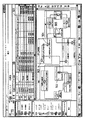
図5は、列501を違反例として表したレプリケーション違反の概略例示ダイヤグラム図である。この場合の違反は“DRアクセス経路停止(outage)”形式のものであり、ストレージコンポーネント502上のボリュームからストレージコンポーネント505におけるそのレプリカとの間の可用性断絶(disruption)を含んでいる。これら2つのストレージコンポーネント間のアクセス経路にはネットワークコンポーネント503及び504も含まれる。このアクセス経路に沿ったどこかにイベントが発生してストレージコンポーネント502及び505間の情報フローが妨害され、それによってこれら2つのストレージコンポーネント間でのボリューム及びレプリカに関わるコピー動作が妨害されると、ストレージコンポーネント505のレプリカはおそらく十分に最新化されず、又は整合しなくなる(コピー動作中に障害が生じた場合)。
FIG. 5 is a schematic illustration diagram of a replication violation showing the
レプリケーション検証プロセスの次のステップ(図2ではステップ212)には、各違反及び当該違反に関わる関連情報の適宜通知が含まれる。関連情報には、例えば、違反タイプ、悪影響を受けるボリューム及びアプリケーション、違反時間、違反の根本原因、等が含まれ得る。違反の原因イベントは、当該イベントの発生又は非発生の何れかの事実により、違反の根本原因として参照される。違反はそうした関連情報に基づいて分類され、どの違反通知をどのパーティーに送るかが適宜のフィルタリングメカニズムにより判定され得る。 The next step of the replication verification process (step 212 in FIG. 2) includes appropriate notification of each violation and related information related to the violation. Related information may include, for example, violation type, volume and application affected, violation time, root cause of violation, and the like. The cause event of the violation is referred to as the root cause of the violation by the fact that the event has occurred or has not occurred. Violations are classified based on such relevant information, and which violation notifications are sent to which party can be determined by an appropriate filtering mechanism.
図6にはレプリケーション違反の根本原因分析の概略例示ダイヤグラム図が示される。
列602は違反601(図5では501とも表示される)の根本原因としてのイベントを識別している。イベントは’05年4月24日午後2:50分の時点で発生し、ストレージコンポーネント502及び505間でのそれ以降のデータトラフィックを妨害する、ネットワークコンポーネント503上でのゾーニング構成のアップデートを含んでいた。この関連情報を入手したシステム管理者は違反を修正するべく、ストレージコンポーネント503に直ちに別のゾーニング構成を送ることができる。
FIG. 6 shows a schematic diagram of a root cause analysis of a replication violation.
違反と関連情報とはリスト及び記憶され、違反情報に適用するフィルタリングルールに基づく適宜の通知メッセージが発生され、適宜のパーティーに送られ得る。違反の修正もまた、説明したメカニズムによって自動検出され、記憶した情報がアップデートされて適宜の通知メッセージが送られ得る。
本プロセスでは、受けたイベント情報(コンポーネントやデータコピーからの)もデータベースのヒストリー構造内に記憶され、アクセス経路の導出結果が各イベントに関連付けされる。このヒストリーデータベースは、環境内のアクセス経路状態の完全エボリューションを表し、それ以降の分析及びサマリーリポート用に使用可能である。
Violations and related information are listed and stored, and appropriate notification messages based on filtering rules applied to the violation information can be generated and sent to appropriate parties. Violation corrections are also automatically detected by the mechanism described, and the stored information can be updated and appropriate notification messages sent.
In this process, the received event information (from the component or data copy) is also stored in the history structure of the database, and the access route derivation result is associated with each event. This history database represents a complete evolution of access path conditions in the environment and can be used for further analysis and summary reporting.
本発明の別の実施例によれば、将来的な変更、イベント、障害がレプリケーション条件に与え得る影響を判定し、そうした影響を事前に防止するべく、そうした変更、イベント、障害をプランニング及びシミュレーションすることができる。
具体的なイベントとしては、将来生じ得る、コンポーネント変更、データコピー機動作、又はコンポーネント故障又はサイト障害、がある。
分析は最新状態の環境コンポーネント及びレプリカを用いて先に説明した1つに類似して実施され、シミュレートしたイベント入力を、特定動作の累積的影響をシミュレートする環境(図2ではステップ204)から収集したイベント情報として検討し、こうした動作が環境内で実際に発生した場合に違反が発生するかどうかを判定する。
According to another embodiment of the present invention, the impact of future changes, events and failures on replication conditions can be determined, and such changes, events and failures can be planned and simulated to prevent such effects in advance. be able to.
Specific events include component changes, data copier operations, or component failures or site failures that may occur in the future.
The analysis is performed similar to the one described above using state-of-the-art environmental components and replicas, and simulated event inputs are used to simulate the cumulative effects of specific actions (step 204 in FIG. 2). It is considered as event information collected from, and it is determined whether a violation occurs when such an operation actually occurs in the environment.
そうした将来的な違反の夫々についての関連情報が、通常の違反(上記説明参照)に対して提供されると同じ方法で発生され提供される。検証後、イノベーションは相当する変更イベントの実施を実際に追跡し、その実施の進捗を追跡し、成功裡に完了したことをリポート(又は違反発生を通知)する。
本発明の更に他の実施例では、レプリケーション違反プロセス中に累積し処理された情報のサマリーレポートが可能とされ得る。最新イノベーションにより収集及び分析した情報は、広範で有益なデータレプリケーション検証のサマリーレポート及びトレンドレポートを発生させ得る。
Relevant information about each such future violation is generated and provided in the same manner as provided for a normal violation (see description above). After validation, the innovation actually tracks the implementation of the corresponding change event, tracks the progress of its implementation, and reports that it has been successfully completed (or reports the occurrence of a violation).
In yet another embodiment of the present invention, a summary report of information accumulated and processed during the replication violation process may be enabled. Information collected and analyzed through the latest innovations can generate extensive and useful data replication verification summary and trend reports.
発生され得るレポート形式の例には、中でも以下のものが含まれる。
**選択したアプリケーション及びその属性のボリュームの全てのレプリカ。
**条件(多過ぎる場合はキャピタルリソースが廃棄され得ることを、少な過ぎればリスクの可能性があることを夫々表す)に関する、各アプリケーションに対するレプリカボリューム数。
**最新の全レプリケーション違反と関連情報パラメータ。
**所定の時間ウィンドウ内で生じた全レプリケーション違反。
**レプリケーション違反の平均修正時間(時間トレンド)。
**障害シナリオ(破滅的なサイト障害)
**アプリケーションのレプリカ数の時間トレンド、レプリカが要するストレージ容量、その他。
Examples of report formats that can be generated include, among others:
** All replicas of the selected application and its attribute volumes.
** The number of replica volumes for each application for the condition (representing that too much capital resources can be discarded, too little represents a potential risk).
** Latest all replication violations and related information parameters.
** All replication violations that occurred within a given time window.
** Replication violation average correction time (time trend).
** Failure scenario (catastrophic site failure)
** Time trend of the number of application replicas, storage capacity required for replicas, etc.
以上、本発明を実施例を参照して説明したが、本発明の内で種々の変更をなし得ることを理解されたい。アクセス経路の種々の様相及びそれらの違反及び取り扱い上のそうした変更は、例えば、2003年10月23日に提出された米国特許出願番号第10/693、632号、2005年4月22日に提出された米国特許出願番号第11/112,942号及び同米国特許出願番号第11/112,624号に記載される。従って、本発明の精神及び範囲は添付する請求の範囲によってのみ限定されるべきである。 Although the present invention has been described with reference to the embodiments, it should be understood that various modifications can be made within the present invention. Various aspects of access paths and their breaches and such changes in handling are described, for example, in US patent application Ser. No. 10 / 693,632, filed Oct. 23, 2003, filed Apr. 22, 2005. U.S. patent application Ser. No. 11 / 112,942 and U.S. Pat. No. 11 / 112,624. Accordingly, the spirit and scope of the present invention should be limited only by the attached claims.
101 レプリカデータ検証マネージャ
102、108、110 ホストコンポーネント
104、106 ストレージコンポーネント
112、114、116 スィッチ又はルーター
118 ネットワークコンポーネント
128 ソースボリューム
130、132、134 ローカルレプリカ
200 プロセスデータフロー
301 アクセス経路
302 経路の冗長性
303 レプリカ数及びコピー動作のタイプ
401、402、403、404、405 時点
101 Replica
Claims (14)
ネットワークのためのレプリカデータポリシーにして、少なくとも、ネットワーク内のストレージコンポーネントに記憶されたレプリカボリュームのためのリカバリーポイント時間(age)条件及びアクセス経路条件、を指定するレプリカデータポリシーを記憶するように構成されたメモリーサブコンポーネントと、
コミュニケーション可能な状態下にネットワークに連結されたネットワークコンポーネントにして、ネットワーク内の前記コンポーネンツが、1つ以上のホストコンポーネントと、当該ホストコンポーネント上で実行されるアプリケーションとを含み得るネットワークコンポーネントと、
メモリーサブコンポーネント及びネットワークコンポーネントに電子的に連結したレプリカデータ検証マネージャにして、該レプリカデータ検証マネージャが、
ネットワークコンポーネントを使用して、レプリカボリュームと関連するアクセス経路セットにして、該セットにおけるアクセス経路が、レプリカボリュームと、ネットワーク内のコンポーネンツの1つとの間のデータフローパスを表すアクセス経路セットを監視し、
ネットワークコンポーネントを使用してネットワーク内のデータ複製を監視し、該データ複製の監視が、レプリカボリュームがネットワーク内のストレージコンポーネントに記憶されたソースボリュームを示したスナップショット時間をレプリカデータ検証マネージャにより確認することを含み、
レプリカボリュームの、該スナップショット時間からの経過時間を表すリカバリーポイント時間を算出し、
算出したリカバリーポイント時間をリカバリーポイント時間条件と比較し、
レプリカボリュームに関連するアクセス経路セットをアクセス経路条件と比較し、
レプリカデータポリシーの条件が違反のものであった場合に違反を通知する、
如く構成されるレプリカデータの検証管理システム。In combination with the connected component tree in the network, a replica data verification management system,
And the replica data policy for the network, at least, to store a replica data policies that specify recovery point time for the replicon Cabo volume stored in storage components in the network (age) condition and access path conditions, a a memory over subcomponents configured,
In the network component coupled to the network under communication possible state, the component tree in the network, and one or more host components, and network components that may include an application running on the host component,
A replica data verification manager electronically coupled to the memory sub-component and the network component ;
Using the network components, and the access path set associated with replicon Cabo volume, access path in said set, and the replicate Cabo volume, access path set representing a data flow path between the one of the components tree in the network Monitor
Monitors data replication within the network by using a network component, the data replication is monitored, replicons Cabo volume snapshot time indicates saw Subo volume stored in the storage component of the replica data verification manager in the network It includes is confirmed by,
The replicon Cabo volume, calculated between the time recovery point representing the elapsed time from the snapshot time,
Compare the calculated recovery point time with the recovery point time condition,
The access path set associated with the replicon Cabo volume compared to the access path condition,
Notify the violation when the conditions of the replica data policy are in violation
A replica data verification management system configured as described above.
ネットワークにおけるコンポーネンツが、1つ以上のホストコンポーネントと、該ホストコンポーネント上で実行されるアプリケーションとを含み得、
前記方法が、レプリカデータ検証マネージャにより、
ネットワークのためのレプリカデータポリシーにして、ネットワーク内のストレージコンポーネントに記憶させたレプリカボリュームのためのリカバリーポイント時間条件及びアクセス経路条件を規定するレプリカデータポリシーをメモリーサブコンポーネントに記憶すること、
レプリカボリュームに関するアクセス経路セットにして、該セットにおけるアクセス経路が、レプリカボリュームと、ネットワーク内のコンポーネンツとの間のデータフローパスを表すアクセス経路セットを監視すること、
ネットワーク内のデータ複製を監視し、該監視が、レプリカボリュームがネットワーク内のストレージコンポーネントに記憶されたソースボリュームを示したスナップショット時間をレプリカデータ検証マネージャにより確認することを含み、
レプリカボリュームの、該スナップショット時間からの経過時間を表すリカバリーポイントの時間を算出すること、
算出したリカバリーポイント時間をリカバリーポイント時間条件と比較すること、
レプリカボリュームに関連するアクセス経路セットをアクセス経路条件と比較すること、
レプリカデータポリシーの条件が違反のものであった場合に違反を通知すること、
を含む方法。A way for monitoring data replication component Tsu in the network in a computer system,
Component in the network tree is, include one or more host components, and applications running on the host component,
The method is performed by a replica data verification manager,
And the replica data policy for the network, storing the replica data policy in the memory sub-component that defines a recovery point time condition and access path conditions for replicon Cabo volume which is stored in storage components in the network,
In the access path set for replicon Cabo volume, the access path in the set, to monitor a replicon Cabo volume, an access route set representing a data flow path between the components tree in the network,
Monitors data replication in a network, the method comprising the monitoring confirms the snapshot time indicates saw Subo volume of replicon Cabo volume has been stored in storage components in the network by the replica data verification manager,
Replicon Cabo volume, calculating the time of recovery point representing the elapsed time from the snapshot time,
Comparing the calculated recovery point time with the recovery point time condition;
Comparing the access path set associated with the replicon Cabo volume access path condition,
Notifying the violation when the conditions of the replica data policy are violated,
Including methods.
Applications Claiming Priority (3)
| Application Number | Priority Date | Filing Date | Title |
|---|---|---|---|
| US72097705P | 2005-09-27 | 2005-09-27 | |
| US60/720,977 | 2005-09-27 | ||
| PCT/US2006/037711 WO2007038617A2 (en) | 2005-09-27 | 2006-09-27 | Methods and systems for validating accessibility and currency of replicated data |
Publications (3)
| Publication Number | Publication Date |
|---|---|
| JP2009510624A JP2009510624A (en) | 2009-03-12 |
| JP2009510624A5 JP2009510624A5 (en) | 2010-11-18 |
| JP5060485B2 true JP5060485B2 (en) | 2012-10-31 |
Family
ID=37900428
Family Applications (1)
| Application Number | Title | Priority Date | Filing Date |
|---|---|---|---|
| JP2008533573A Active JP5060485B2 (en) | 2005-09-27 | 2006-09-27 | A method and system for verifying the availability and freshness of replicated data. |
Country Status (4)
| Country | Link |
|---|---|
| US (2) | US7702667B2 (en) |
| EP (2) | EP1943594A4 (en) |
| JP (1) | JP5060485B2 (en) |
| WO (1) | WO2007038617A2 (en) |
Families Citing this family (39)
| Publication number | Priority date | Publication date | Assignee | Title |
|---|---|---|---|---|
| US7961594B2 (en) * | 2002-10-23 | 2011-06-14 | Onaro, Inc. | Methods and systems for history analysis for access paths in networks |
| US7546333B2 (en) * | 2002-10-23 | 2009-06-09 | Netapp, Inc. | Methods and systems for predictive change management for access paths in networks |
| US8560671B1 (en) | 2003-10-23 | 2013-10-15 | Netapp, Inc. | Systems and methods for path-based management of virtual servers in storage network environments |
| EP1943594A4 (en) * | 2005-09-27 | 2009-12-16 | Onaro | Methods and systems for validating accessibility and currency of replicated data |
| EP1955235A4 (en) * | 2005-11-25 | 2010-11-10 | Continuity Software Ltd | System and method of managing data protection resources |
| US9411969B2 (en) * | 2005-11-25 | 2016-08-09 | Continuity Software Ltd. | System and method of assessing data protection status of data protection resources |
| US8826032B1 (en) | 2006-12-27 | 2014-09-02 | Netapp, Inc. | Systems and methods for network change discovery and host name resolution in storage network environments |
| US8332860B1 (en) | 2006-12-30 | 2012-12-11 | Netapp, Inc. | Systems and methods for path-based tier-aware dynamic capacity management in storage network environments |
| US9042263B1 (en) | 2007-04-06 | 2015-05-26 | Netapp, Inc. | Systems and methods for comparative load analysis in storage networks |
| US20080281876A1 (en) * | 2007-05-10 | 2008-11-13 | Hitachi, Ltd. | Methods and apparatus to recover data and configuration of storage system |
| US20130110777A1 (en) * | 2007-06-06 | 2013-05-02 | Kunio Kamimura | Synchronization of data edited in parallel |
| BRPI0817505A2 (en) * | 2007-09-28 | 2015-03-24 | Apertio Ltd | System and method for replication and timing |
| JP4598817B2 (en) * | 2007-12-18 | 2010-12-15 | 株式会社日立製作所 | Computer system and data loss avoidance method |
| US7930163B2 (en) * | 2008-04-30 | 2011-04-19 | Netapp, Inc. | Modeling a storage environment at various times |
| US8868400B2 (en) * | 2008-04-30 | 2014-10-21 | Netapp, Inc. | Modeling storage environments |
| US8370679B1 (en) * | 2008-06-30 | 2013-02-05 | Symantec Corporation | Method, apparatus and system for improving failover within a high availability disaster recovery environment |
| US8135670B2 (en) * | 2008-07-22 | 2012-03-13 | International Business Machines Corporation | Embedded change logging for data synchronization |
| US8898108B2 (en) * | 2009-01-14 | 2014-11-25 | Vmware, Inc. | System and method for scheduling data storage replication over a network |
| US8341115B1 (en) * | 2009-12-26 | 2012-12-25 | Emc Corporation | Dynamically switching between synchronous and asynchronous replication |
| US8560292B2 (en) * | 2010-02-09 | 2013-10-15 | Google Inc. | Location assignment daemon (LAD) simulation system and method |
| US8868508B2 (en) | 2010-02-09 | 2014-10-21 | Google Inc. | Storage of data in a distributed storage system |
| US8954979B1 (en) * | 2011-08-15 | 2015-02-10 | Netapp, Inc. | Method and system for managing resources in a network |
| US10089323B2 (en) | 2012-04-05 | 2018-10-02 | Microsoft Technology Licensing, Llc | Telemetry system for a cloud synchronization system |
| US9213590B2 (en) | 2012-06-27 | 2015-12-15 | Brocade Communications Systems, Inc. | Network monitoring and diagnostics |
| US9304815B1 (en) | 2013-06-13 | 2016-04-05 | Amazon Technologies, Inc. | Dynamic replica failure detection and healing |
| US10027535B1 (en) * | 2013-09-27 | 2018-07-17 | Juniper Networks, Inc. | Systems and methods for managing device configurations at various levels of abstraction |
| US10693955B2 (en) * | 2013-12-14 | 2020-06-23 | Netapp, Inc. | Techniques for SAN storage cluster synchronous disaster recovery |
| IN2014DE00764A (en) * | 2014-03-14 | 2015-09-18 | Netapp Inc | |
| JP6286251B2 (en) * | 2014-03-28 | 2018-02-28 | 株式会社日立製作所 | Distributed file system and data availability management control method thereof |
| US10169439B2 (en) * | 2015-06-19 | 2019-01-01 | Sap Se | Multi-source asynchronous table replication |
| US10268743B2 (en) | 2015-06-19 | 2019-04-23 | Sap Se | Distributed database transaction protocol |
| US10284417B2 (en) * | 2015-06-22 | 2019-05-07 | Arista Networks, Inc. | Method and system for sharing state between network elements |
| US9477555B1 (en) | 2015-11-16 | 2016-10-25 | International Business Machines Corporation | Optimized disaster-recovery-as-a-service system |
| US10635559B2 (en) | 2016-11-29 | 2020-04-28 | International Business Machines Corporation | Maintaining data integrity over multiple applications |
| US10389596B2 (en) * | 2017-03-30 | 2019-08-20 | Ca, Inc. | Discovering application topologies |
| US11671329B2 (en) | 2018-04-04 | 2023-06-06 | Arista Networks, Inc. | Computation of network flooding topologies |
| US11288237B2 (en) * | 2018-11-06 | 2022-03-29 | Red Hat, Inc. | Distributed file system with thin arbiter node |
| US11301462B1 (en) | 2020-03-31 | 2022-04-12 | Amazon Technologies, Inc. | Real-time data validation using lagging replica databases |
| US11811867B2 (en) * | 2020-09-01 | 2023-11-07 | International Business Machines Corporation | Data transmission routing based on replication path capability |
Family Cites Families (81)
| Publication number | Priority date | Publication date | Assignee | Title |
|---|---|---|---|---|
| US5043866A (en) * | 1988-04-08 | 1991-08-27 | International Business Machines Corporation | Soft checkpointing system using log sequence numbers derived from stored data pages and log records for database recovery |
| JPH0827755B2 (en) * | 1991-02-15 | 1996-03-21 | インターナショナル・ビジネス・マシーンズ・コーポレイション | How to access data units at high speed |
| EP0516900B1 (en) * | 1991-06-04 | 1996-05-01 | International Business Machines Corporation | Data backup and recovery in a data processing system |
| US5774377A (en) | 1991-07-30 | 1998-06-30 | Hewlett-Packard Company | Method and apparatus for monitoring a subsystem within a distributed system for providing an archive of events within a certain time of a trap condition |
| US5280611A (en) * | 1991-11-08 | 1994-01-18 | International Business Machines Corporation | Method for managing database recovery from failure of a shared store in a system including a plurality of transaction-based systems of the write-ahead logging type |
| JP3213766B2 (en) | 1992-03-16 | 2001-10-02 | 株式会社日立製作所 | Replicate file update system |
| US6347335B1 (en) | 1995-09-22 | 2002-02-12 | Emc Corporation | System using a common and local event logs for logging event information generated by plurality of devices for determining problem in storage access operations |
| US5684800A (en) | 1995-11-15 | 1997-11-04 | Cabletron Systems, Inc. | Method for establishing restricted broadcast groups in a switched network |
| US6014673A (en) * | 1996-12-05 | 2000-01-11 | Hewlett-Packard Company | Simultaneous use of database and durable store in work flow and process flow systems |
| US5940819A (en) | 1997-08-29 | 1999-08-17 | International Business Machines Corporation | User specification of query access paths in a relational database management system |
| US6327598B1 (en) | 1997-11-24 | 2001-12-04 | International Business Machines Corporation | Removing a filled-out form from a non-interactive web browser cache to an interactive web browser cache |
| US6223176B1 (en) | 1998-09-25 | 2001-04-24 | International Business Machines Corporation | Method and computer program product for implementing highly concurrent record insertion in an ordinal number dependent database |
| CA2349010A1 (en) | 1998-10-27 | 2000-05-04 | Fujitsu Network Communications, Inc. | Event based rate policing with a jumping window |
| US6909700B1 (en) | 1998-11-24 | 2005-06-21 | Lucent Technologies Inc. | Network topology optimization methods and apparatus for designing IP networks with performance guarantees |
| US6795399B1 (en) | 1998-11-24 | 2004-09-21 | Lucent Technologies Inc. | Link capacity computation methods and apparatus for designing IP networks with performance guarantees |
| US6240463B1 (en) | 1998-11-24 | 2001-05-29 | Lucent Technologies Inc. | Router placement methods and apparatus for designing IP networks with performance guarantees |
| US6434626B1 (en) | 1999-01-14 | 2002-08-13 | Compaq Information Technologies Group, L.P. | Method and apparatus for low latency network performance monitoring |
| US6751228B1 (en) | 1999-03-23 | 2004-06-15 | Yamaha Corporation | Packet handler of audio data by isochronous mode |
| US20040030768A1 (en) | 1999-05-25 | 2004-02-12 | Suban Krishnamoorthy | Unified system and method for downloading code to heterogeneous devices in distributed storage area networks |
| US6636981B1 (en) | 2000-01-06 | 2003-10-21 | International Business Machines Corporation | Method and system for end-to-end problem determination and fault isolation for storage area networks |
| US6691169B1 (en) | 2000-02-01 | 2004-02-10 | At&T Corp. | Method and apparatus for detecting route advertisement violations in a network of interconnected peers |
| US6701449B1 (en) | 2000-04-20 | 2004-03-02 | Ciprico, Inc. | Method and apparatus for monitoring and analyzing network appliance status information |
| US7284244B1 (en) | 2000-05-02 | 2007-10-16 | Microsoft Corporation | Resource manager architecture with dynamic resource allocation among multiple configurations |
| US6985937B1 (en) | 2000-05-11 | 2006-01-10 | Ensim Corporation | Dynamically modifying the resources of a virtual server |
| US7103653B2 (en) | 2000-06-05 | 2006-09-05 | Fujitsu Limited | Storage area network management system, method, and computer-readable medium |
| JP4073161B2 (en) | 2000-12-06 | 2008-04-09 | 株式会社日立製作所 | Disk storage access system |
| US7054782B2 (en) | 2000-12-29 | 2006-05-30 | Medtronic, Inc. | Non-conformance monitoring and control techniques for an implantable medical device |
| US7051029B1 (en) | 2001-01-05 | 2006-05-23 | Revenue Science, Inc. | Identifying and reporting on frequent sequences of events in usage data |
| US6904143B1 (en) | 2001-03-05 | 2005-06-07 | Verizon Corporate Services Group Inc. | Apparatus and method for logging events that occur when interacting with an automated call center system |
| US7028228B1 (en) | 2001-03-28 | 2006-04-11 | The Shoregroup, Inc. | Method and apparatus for identifying problems in computer networks |
| US7269157B2 (en) | 2001-04-10 | 2007-09-11 | Internap Network Services Corporation | System and method to assure network service levels with intelligent routing |
| US20020194407A1 (en) | 2001-04-25 | 2002-12-19 | Kim Hyon T. | Maintaining fabric device configuration through dynamic reconfiguration |
| US20020194324A1 (en) | 2001-04-26 | 2002-12-19 | Aloke Guha | System for global and local data resource management for service guarantees |
| JP4039821B2 (en) | 2001-05-09 | 2008-01-30 | 株式会社日立製作所 | Computer system using disk controller and its operation service |
| US7380239B1 (en) | 2001-05-31 | 2008-05-27 | Oracle International Corporation | Method and mechanism for diagnosing computer applications using traces |
| US7376937B1 (en) | 2001-05-31 | 2008-05-20 | Oracle International Corporation | Method and mechanism for using a meta-language to define and analyze traces |
| US6996580B2 (en) | 2001-06-22 | 2006-02-07 | International Business Machines Corporation | System and method for granular control of message logging |
| US7343410B2 (en) | 2001-06-28 | 2008-03-11 | Finisar Corporation | Automated creation of application data paths in storage area networks |
| US6904561B1 (en) | 2001-07-19 | 2005-06-07 | Microsoft Corp. | Integrated timeline and logically-related list view |
| US7464156B2 (en) | 2001-09-07 | 2008-12-09 | Sanrad, Ltd. | Load balancing method for exchanging data between multiple hosts and storage entities, in IP based storage area network |
| US20030055932A1 (en) | 2001-09-19 | 2003-03-20 | Dell Products L.P. | System and method for configuring a storage area network |
| WO2003054711A1 (en) | 2001-09-21 | 2003-07-03 | Polyserve, Inc. | A system and method for management of a storage area network |
| JP2003108420A (en) | 2001-09-27 | 2003-04-11 | Hitachi Ltd | Data storage system and method of controlling the system |
| US20030154271A1 (en) | 2001-10-05 | 2003-08-14 | Baldwin Duane Mark | Storage area network methods and apparatus with centralized management |
| JP3879471B2 (en) | 2001-10-10 | 2007-02-14 | 株式会社日立製作所 | Computer resource allocation method |
| US7127633B1 (en) | 2001-11-15 | 2006-10-24 | Xiotech Corporation | System and method to failover storage area network targets from one interface to another |
| US7035922B2 (en) * | 2001-11-27 | 2006-04-25 | Microsoft Corporation | Non-invasive latency monitoring in a store-and-forward replication system |
| US7000154B1 (en) | 2001-11-28 | 2006-02-14 | Intel Corporation | System and method for fault detection and recovery |
| US7349961B2 (en) | 2001-12-07 | 2008-03-25 | Hitachi, Ltd. | Detecting configuration inconsistency in storage networks |
| US7058702B2 (en) | 2002-01-04 | 2006-06-06 | Hewlett-Packard Development Company, L.P. | Efficient validation of network configuration change commands |
| FR2835630B1 (en) | 2002-02-07 | 2004-03-26 | Bull Sa | METHOD FOR THE AUTOMATIC UPDATE OF A SYSTEM DISK ACCESS PATH OF A HARDWARE PERIMETER, SYSTEM FOR EXECUTING THIS METHOD AND MEMORY USED IN THIS SYSTEM |
| US6973595B2 (en) | 2002-04-05 | 2005-12-06 | International Business Machines Corporation | Distributed fault detection for data storage networks |
| US7194538B1 (en) | 2002-06-04 | 2007-03-20 | Veritas Operating Corporation | Storage area network (SAN) management system for discovering SAN components using a SAN management server |
| US6990520B2 (en) | 2002-06-12 | 2006-01-24 | Prisa Networks, Inc. | System and method for managing computer networks |
| US20030237017A1 (en) | 2002-06-24 | 2003-12-25 | Jibbe Mahmoud Khaled | Component fault isolation in a storage area network |
| US7313793B2 (en) | 2002-07-11 | 2007-12-25 | Microsoft Corporation | Method for forking or migrating a virtual machine |
| US7055068B2 (en) | 2002-07-25 | 2006-05-30 | Lsi Logic Corporation | Method for validating operation of a fibre link |
| US7512954B2 (en) | 2002-07-29 | 2009-03-31 | Oracle International Corporation | Method and mechanism for debugging a series of related events within a computer system |
| US7379990B2 (en) | 2002-08-12 | 2008-05-27 | Tsao Sheng Ted Tai | Distributed virtual SAN |
| US7370064B2 (en) * | 2002-08-06 | 2008-05-06 | Yousefi Zadeh Homayoun | Database remote replication for back-end tier of multi-tier computer systems |
| US7120654B2 (en) | 2002-08-20 | 2006-10-10 | Veritas Operating Corporation | System and method for network-free file replication in a storage area network |
| US7260628B2 (en) | 2002-09-06 | 2007-08-21 | Hitachi, Ltd. | Event notification in storage networks |
| US8019806B2 (en) | 2002-10-17 | 2011-09-13 | Brocade Communications Systems, Inc. | Method and apparatus for displaying network fabric data |
| US7546333B2 (en) | 2002-10-23 | 2009-06-09 | Netapp, Inc. | Methods and systems for predictive change management for access paths in networks |
| WO2004038700A2 (en) | 2002-10-23 | 2004-05-06 | Onaro | Method and system for validating logical end-to-end access paths in storage area networks |
| US7640267B2 (en) | 2002-11-20 | 2009-12-29 | Radar Networks, Inc. | Methods and systems for managing entities in a computing device using semantic objects |
| JP2004192305A (en) | 2002-12-11 | 2004-07-08 | Hitachi Ltd | METHOD AND SYSTEM FOR MANAGING iSCSI STORAGE |
| US20040243699A1 (en) | 2003-05-29 | 2004-12-02 | Mike Koclanes | Policy based management of storage resources |
| US7287043B2 (en) * | 2003-08-21 | 2007-10-23 | International Business Machines Corporation | System and method for asynchronous data replication without persistence for distributed computing |
| US7209934B2 (en) * | 2003-11-21 | 2007-04-24 | Bellsouth Intellectual Property Corporation | Methods, systems and computer program products for monitoring files |
| US7340646B2 (en) | 2004-05-03 | 2008-03-04 | International Business Machines Corporation | Apparatus, system, and method for resource group backup |
| US20060004830A1 (en) | 2004-06-07 | 2006-01-05 | Lora Brian M | Agent-less systems, methods and computer program products for managing a plurality of remotely located data storage systems |
| US20060020691A1 (en) | 2004-07-20 | 2006-01-26 | Hewlett-Packard Development Company, L.P. | Load balancing based on front-end utilization |
| US7774365B2 (en) | 2004-08-31 | 2010-08-10 | Morgan Stanley | Organizational reference data and entitlement system |
| US7493350B2 (en) | 2004-10-25 | 2009-02-17 | International Business Machines Corporation | Entity based configurable data management system and method |
| US7552208B2 (en) | 2005-01-18 | 2009-06-23 | Microsoft Corporation | Methods for managing capacity |
| US7707015B2 (en) | 2005-01-18 | 2010-04-27 | Microsoft Corporation | Methods for capacity management |
| JP4739786B2 (en) | 2005-03-28 | 2011-08-03 | 株式会社日立製作所 | Data relocation method |
| EP1943594A4 (en) | 2005-09-27 | 2009-12-16 | Onaro | Methods and systems for validating accessibility and currency of replicated data |
| JP2007140746A (en) * | 2005-11-16 | 2007-06-07 | Hitachi Ltd | Computer system, management computer and recovery management method |
| US8572330B2 (en) | 2005-12-19 | 2013-10-29 | Commvault Systems, Inc. | Systems and methods for granular resource management in a storage network |
-
2006
- 2006-09-27 EP EP06804208A patent/EP1943594A4/en not_active Withdrawn
- 2006-09-27 WO PCT/US2006/037711 patent/WO2007038617A2/en active Application Filing
- 2006-09-27 JP JP2008533573A patent/JP5060485B2/en active Active
- 2006-09-27 US US11/529,748 patent/US7702667B2/en active Active
- 2006-09-27 EP EP12157180A patent/EP2492813A3/en not_active Withdrawn
-
2010
- 2010-02-24 US US12/712,068 patent/US8775387B2/en active Active
Also Published As
| Publication number | Publication date |
|---|---|
| US8775387B2 (en) | 2014-07-08 |
| EP1943594A2 (en) | 2008-07-16 |
| EP2492813A3 (en) | 2013-01-30 |
| JP2009510624A (en) | 2009-03-12 |
| WO2007038617A3 (en) | 2007-11-08 |
| US20070088763A1 (en) | 2007-04-19 |
| US7702667B2 (en) | 2010-04-20 |
| EP1943594A4 (en) | 2009-12-16 |
| US20100153350A1 (en) | 2010-06-17 |
| WO2007038617A2 (en) | 2007-04-05 |
| EP2492813A2 (en) | 2012-08-29 |
Similar Documents
| Publication | Publication Date | Title |
|---|---|---|
| JP5060485B2 (en) | A method and system for verifying the availability and freshness of replicated data. | |
| US7961594B2 (en) | Methods and systems for history analysis for access paths in networks | |
| CN109074297B (en) | Enabling data integrity checking and faster application recovery in synchronously replicated datasets | |
| JP6734866B2 (en) | Resynchronization to the first storage system after failover to the second storage system that mirrors the first storage system | |
| US7191198B2 (en) | Storage operation management program and method and a storage management computer | |
| US7546333B2 (en) | Methods and systems for predictive change management for access paths in networks | |
| JP4939174B2 (en) | Method for managing failures in a mirrored system | |
| JP4827564B2 (en) | How to display the copy pair status | |
| CN109815049A (en) | Node delay machine restoration methods, device, electronic equipment and storage medium | |
| US7840595B1 (en) | Techniques for determining an implemented data protection policy | |
| JP4686303B2 (en) | Storage management method and storage system | |
| JP2009510624A5 (en) | ||
| US8321867B1 (en) | Request processing for stateless conformance engine | |
| JP5352027B2 (en) | Computer system management method and management apparatus | |
| JP2006185108A (en) | Management computer for managing data of storage system, and data management method | |
| US11372886B2 (en) | Method to dynamically detect objects out of sync in an active mirroring environment | |
| US11237921B2 (en) | Protecting storage backup configuration | |
| JP7339542B2 (en) | Management device, management system and management method | |
| WO2005106694A2 (en) | Methods and systems for history analysis and predictive change management for access paths in networks | |
| JP2016009218A (en) | Redundant system, redundancy method, and redundancy program | |
| Parui et al. | Monitoring Availability Groups | |
| WO2017145286A1 (en) | Storage system management method | |
| CN113138722A (en) | Replicated snapshot method, system, and medium for distributed block storage system | |
| WO2020021548A1 (en) | Handling failures in distributed data system | |
| Rana | A Fault-Tolerant Technique for Site Recovery in Wideband Networks |
Legal Events
| Date | Code | Title | Description |
|---|---|---|---|
| A521 | Request for written amendment filed |
Free format text: JAPANESE INTERMEDIATE CODE: A523 Effective date: 20090928 |
|
| A621 | Written request for application examination |
Free format text: JAPANESE INTERMEDIATE CODE: A621 Effective date: 20090928 |
|
| A521 | Request for written amendment filed |
Free format text: JAPANESE INTERMEDIATE CODE: A523 Effective date: 20100927 |
|
| A131 | Notification of reasons for refusal |
Free format text: JAPANESE INTERMEDIATE CODE: A131 Effective date: 20111220 |
|
| A601 | Written request for extension of time |
Free format text: JAPANESE INTERMEDIATE CODE: A601 Effective date: 20120321 |
|
| A602 | Written permission of extension of time |
Free format text: JAPANESE INTERMEDIATE CODE: A602 Effective date: 20120328 |
|
| A521 | Request for written amendment filed |
Free format text: JAPANESE INTERMEDIATE CODE: A523 Effective date: 20120619 |
|
| TRDD | Decision of grant or rejection written | ||
| A01 | Written decision to grant a patent or to grant a registration (utility model) |
Free format text: JAPANESE INTERMEDIATE CODE: A01 Effective date: 20120710 |
|
| A01 | Written decision to grant a patent or to grant a registration (utility model) |
Free format text: JAPANESE INTERMEDIATE CODE: A01 |
|
| A61 | First payment of annual fees (during grant procedure) |
Free format text: JAPANESE INTERMEDIATE CODE: A61 Effective date: 20120803 |
|
| FPAY | Renewal fee payment (event date is renewal date of database) |
Free format text: PAYMENT UNTIL: 20150810 Year of fee payment: 3 |
|
| R150 | Certificate of patent or registration of utility model |
Ref document number: 5060485 Country of ref document: JP Free format text: JAPANESE INTERMEDIATE CODE: R150 Free format text: JAPANESE INTERMEDIATE CODE: R150 |
|
| R250 | Receipt of annual fees |
Free format text: JAPANESE INTERMEDIATE CODE: R250 |
|
| R250 | Receipt of annual fees |
Free format text: JAPANESE INTERMEDIATE CODE: R250 |
|
| R250 | Receipt of annual fees |
Free format text: JAPANESE INTERMEDIATE CODE: R250 |
|
| R250 | Receipt of annual fees |
Free format text: JAPANESE INTERMEDIATE CODE: R250 |
|
| R250 | Receipt of annual fees |
Free format text: JAPANESE INTERMEDIATE CODE: R250 |
|
| R250 | Receipt of annual fees |
Free format text: JAPANESE INTERMEDIATE CODE: R250 |
|
| R250 | Receipt of annual fees |
Free format text: JAPANESE INTERMEDIATE CODE: R250 |
|
| R250 | Receipt of annual fees |
Free format text: JAPANESE INTERMEDIATE CODE: R250 |
|
| R250 | Receipt of annual fees |
Free format text: JAPANESE INTERMEDIATE CODE: R250 |