JP5056314B2 - Image recording device - Google Patents

Image recording device Download PDF

Info

Publication number
JP5056314B2
JP5056314B2 JP2007254648A JP2007254648A JP5056314B2 JP 5056314 B2 JP5056314 B2 JP 5056314B2 JP 2007254648 A JP2007254648 A JP 2007254648A JP 2007254648 A JP2007254648 A JP 2007254648A JP 5056314 B2 JP5056314 B2 JP 5056314B2
Authority
JP
Japan
Prior art keywords
roller
recording
recording medium
paper
pair
Prior art date
Legal status (The legal status is an assumption and is not a legal conclusion. Google has not performed a legal analysis and makes no representation as to the accuracy of the status listed.)
Expired - Fee Related
Application number
JP2007254648A
Other languages
Japanese (ja)
Other versions
JP2009083232A (en
Inventor
雄太 内野
貴志 大濱
真種 棚橋
亘 杉山
範幸 川俣
Current Assignee (The listed assignees may be inaccurate. Google has not performed a legal analysis and makes no representation or warranty as to the accuracy of the list.)
Brother Industries Ltd
Original Assignee
Brother Industries Ltd
Priority date (The priority date is an assumption and is not a legal conclusion. Google has not performed a legal analysis and makes no representation as to the accuracy of the date listed.)
Filing date
Publication date
Application filed by Brother Industries Ltd filed Critical Brother Industries Ltd
Priority to JP2007254648A priority Critical patent/JP5056314B2/en
Priority to US12/239,517 priority patent/US8092004B2/en
Priority to CN2008101681442A priority patent/CN101396927B/en
Publication of JP2009083232A publication Critical patent/JP2009083232A/en
Application granted granted Critical
Publication of JP5056314B2 publication Critical patent/JP5056314B2/en
Expired - Fee Related legal-status Critical Current
Anticipated expiration legal-status Critical

Links

Images

Classifications

    • BPERFORMING OPERATIONS; TRANSPORTING
    • B41PRINTING; LINING MACHINES; TYPEWRITERS; STAMPS
    • B41JTYPEWRITERS; SELECTIVE PRINTING MECHANISMS, i.e. MECHANISMS PRINTING OTHERWISE THAN FROM A FORME; CORRECTION OF TYPOGRAPHICAL ERRORS
    • B41J3/00Typewriters or selective printing or marking mechanisms characterised by the purpose for which they are constructed
    • B41J3/60Typewriters or selective printing or marking mechanisms characterised by the purpose for which they are constructed for printing on both faces of the printing material

Description

本発明は、画像記録装置に関するものである。   The present invention relates to an image recording apparatus.

従来より、記録媒体の両面に画像を記録可能なインクジェット方式の画像記録装置が知られている。一方、次の特許文献1には、レーザー方式の複写機に関し、感光ドラム7に向けて一対のフィードローラ1から一対のレジストローラ2を介して用紙を搬送する場合に、一対のフィードローラ1と一対のレジストローラ2との間で用紙を撓ませた状態で搬送することで、ジャムが発生したり、用紙が引っ張られたりするのを防止する技術が記載されている。   2. Description of the Related Art Conventionally, ink jet type image recording apparatuses capable of recording images on both sides of a recording medium are known. On the other hand, the following Patent Document 1 relates to a laser-type copying machine, and when a sheet is conveyed from a pair of feed rollers 1 to a photosensitive drum 7 via a pair of registration rollers 2, A technique for preventing a jam from occurring or a sheet from being pulled by conveying the sheet in a bent state between the pair of registration rollers 2 is described.

この複写機は、レーザー方式であり、用紙の裏面に画像を記録するために、仮に、再度、感光ドラム7に向けて一対のフィードローラ1から一対のレジストローラ2を介して用紙を搬送する場合であっても、用紙の表面に記録した画像を定着装置で定着させた後であれば、用紙の表面に記録された画像がフィードローラ1やレジストローラ2に転写する恐れはなかった。
特開2005−162446号公報(段落第「0024」乃至「0029」、図2等)
This copying machine is a laser system, and in order to record an image on the back side of the paper, the paper is transported again from the pair of feed rollers 1 to the photosensitive drum 7 via the pair of registration rollers 2. However, there is no fear that the image recorded on the surface of the paper is transferred to the feed roller 1 or the registration roller 2 after the image recorded on the surface of the paper is fixed by the fixing device.
Japanese Unexamined Patent Publication No. 2005-162446 (paragraphs “0024” to “0029”, FIG. 2 etc.)

他方、本出願人は、記録媒体の両面に画像を記録可能なインクジェット方式の画像記録装置であって、給紙ローラから記録ヘッドに記録媒体を給紙し、記録ヘッドで記録媒体の表面に画像を記録した後で、その表面が給紙ローラに当接するように一対の送りローラで記録媒体を搬送し、再び、給紙ローラによって記録ヘッドに記録媒体を給紙して、記録媒体の裏面に画像を記録する画像記録装置を提案している(未公知)。   On the other hand, the present applicant is an ink jet type image recording apparatus capable of recording images on both sides of a recording medium, and feeds the recording medium from a paper feed roller to the recording head, and the recording head uses the image on the surface of the recording medium. After recording, the recording medium is conveyed by a pair of feed rollers so that the front surface of the recording medium is in contact with the paper feeding roller, and the recording medium is again fed to the recording head by the paper feeding roller, An image recording apparatus for recording an image has been proposed (unknown).

この未公知の画像記録装置は、上述した複写機とは異なり、インクジェット方式であり、レーザー方式に比べて記録媒体に記録した画像の定着率が悪い上、画像が記録されている記録媒体の表面が給紙ローラに当接するように構成されているので、一対の送りローラと給紙ローラとによって記録媒体が搬送されている場合に、記録媒体の表面に記録されている画像が給紙ローラに転写され、記録媒体の表面に記録された画像が損傷してしまうという問題点があった。   Unlike the above-described copying machine, this unknown image recording apparatus is an ink jet type, and has a lower fixing rate of an image recorded on the recording medium than the laser type, and the surface of the recording medium on which the image is recorded. Since the recording medium is conveyed by the pair of feed rollers and the paper feed roller, the image recorded on the surface of the recording medium is transferred to the paper feed roller. There is a problem in that the image transferred and recorded on the surface of the recording medium is damaged.

本発明は上述した問題点を解決するためになされたものであり、記録媒体の表面に記録された画像を損傷させることなく、記録媒体の両面に画像を記録することができる画像記録装置を提供することを目的としている。   The present invention has been made to solve the above-described problems, and provides an image recording apparatus capable of recording an image on both sides of a recording medium without damaging the image recorded on the surface of the recording medium. The purpose is to do.

この目的を達成するために、請求項1記載の画像記録装置は、記録媒体にインクを吐出して画像を記録する記録ヘッドと、トレイに積載されている記録媒体に当接して、駆動源によって回転駆動されその記録媒体を給紙する給紙ローラとを備え、前記記録媒体の表面と裏面との両面に画像を記録可能なものであって、前記記録ヘッドよりも下流側に配置され、正転および逆転可能に構成され、前記記録ヘッドを通過した記録媒体を挟持して、その挟持した記録媒体を外部に向けて、又は、前記記録媒体の前記記録ヘッドにより記録された表面が前記給紙ローラに当接するように再び前記給紙ローラに向けて搬送する一対の送りローラと、その一対の送りローラと、前記記録ヘッドとを結ぶ経路から枝分かれして、前記給紙ローラに向かって延びる裏面用経路と、その裏面用経路において前記記録媒体が撓んだ状態で搬送されるように、前記一対の送りローラと前記給紙ローラとを駆動させる駆動制御手段とを備え、前記一対の送りローラのうち、先に前記記録媒体の表面に当接する一方の送りローラは、他方の送りローラに従動して回転する従動ローラであり、その従動ローラを一端側に回転自在に軸支して上流側に延び、前記他方の送りローラの回転軸を中心に回動可能に構成され、他端側が前記記録媒体に当接して、前記一対の送りローラに挟持されている記録媒体を、上流側に位置している先端部から前記裏面用経路に誘導する経路切換アームを備えている。
In order to achieve this object, an image recording apparatus according to claim 1 is in contact with a recording head for recording an image by ejecting ink onto a recording medium, and a recording medium loaded on a tray. A recording roller that is driven to rotate and feeds the recording medium, and is capable of recording images on both the front and back surfaces of the recording medium, and is disposed on the downstream side of the recording head. The recording medium that is configured to be able to rotate and reverse is sandwiched, the recording medium that has passed through the recording head is sandwiched, and the sandwiched recording medium is directed outward, or the surface of the recording medium that is recorded by the recording head is the paper feed A pair of feed rollers that are transported again toward the paper feed roller so as to contact the rollers, and a path that branches from the pair of feed rollers and the recording head, and extends toward the paper feed roller. That the back-surface path, as carried in a bent state is the recording medium in its rear surface path, and a drive control means for driving and said feed roller and the pair of feed rollers, the pair Of the feed rollers, one feed roller that contacts the surface of the recording medium first is a follower roller that rotates following the other feed roller, and the follower roller is rotatably supported on one end side. A recording medium extending upstream and configured to be rotatable about the rotation axis of the other feeding roller and having the other end abutted against the recording medium and sandwiched between the pair of feeding rollers is disposed upstream. And a path switching arm for guiding the back surface path from the distal end located at the position .

請求項2記載の画像記録装置は、請求項1に記載の画像記録装置において、前記駆動制御手段は、前記一対の送りローラから前記裏面用経路を通って搬送される記録媒体が前記給紙ローラに当接した後も前記一対の送りローラを駆動させ、所定時間経過後に、前記給紙ローラを駆動させる。   The image recording apparatus according to claim 2, wherein the drive control unit is configured such that the recording medium conveyed from the pair of feed rollers through the back surface path is the sheet feeding roller. The pair of feed rollers are driven even after contact with each other, and the paper feed roller is driven after a predetermined time has elapsed.

請求項3記載の画像記録装置は、請求項1又は2に記載の画像記録装置において、前記駆動制御手段は、前記一対の送りローラによる前記記録媒体の搬送量が前記給紙ローラによる前記記録媒体の搬送量よりも大きくなるように、前記一対の送りローラと前記給紙ローラとを同時に駆動させる。   The image recording apparatus according to claim 3, wherein the drive control unit is configured such that the conveyance amount of the recording medium by the pair of feeding rollers is the recording medium by the sheet feeding roller. The pair of feed rollers and the paper feed roller are simultaneously driven so as to be larger than the carry amount.

請求項4記載の画像記録装置は、請求項1又は2に記載の画像記録装置において、前記駆動制御手段は、前記一対の送りローラによって前記記録媒体が搬送された後に、その一対の送りローラによって搬送された搬送量よりも少ない搬送量で前記記録媒体が前記給紙ローラによって搬送されるように、前記一対の送りローラと前記給紙ローラとを交互に駆動させる。   According to a fourth aspect of the present invention, in the image recording apparatus according to the first or second aspect, the drive control means uses the pair of feed rollers after the recording medium is conveyed by the pair of feed rollers. The pair of feed rollers and the paper feed roller are alternately driven so that the recording medium is transported by the paper feed roller with a transport amount smaller than the transported amount.

請求項記載の画像記録装置は、請求項1からのいずれかに記載の画像記録装置において、前記経路切換アームの他端側には、前記記録媒体に当接する補助ローラが回転自在に軸支されている。
The image recording apparatus according to claim 5 is the image recording apparatus according to any one of claims 1 to 4 , wherein an auxiliary roller contacting the recording medium is rotatably provided at the other end of the path switching arm. It is supported.

請求項1記載の画像記録装置によれば、記録ヘッドによって表面に画像が形成された記録媒体は、一対の送りローラに挟持され、一対の送りローラによって表面が給紙ローラに当接するように、裏面用経路を介して再び給紙ローラに向けて搬送される。その後、記録媒体は、一対の送りローラと給紙ローラとによって、更に下流側に搬送される。この場合、一対の送りローラと給紙ローラとは、駆動制御手段によって裏面用経路において記録媒体が撓んだ状態で搬送されるように制御されている。よって、一対の送りローラと給紙ローラとによって記録媒体を撓ませることなく搬送する場合に比べ、給紙ローラの搬送負荷が軽減され、給紙ローラがスリップし難くなり、給紙ローラがスリップすることで給紙ローラに当接する記録媒体の表面に記録された画像が給紙ローラに転写され、記録媒体の表面に記録された画像が損傷するのを抑制することができるという効果がある。
また、一対の送りローラのうち、先に記録媒体の表面に当接する一方の送りローラは、他方の送りローラに従動して回転する従動ローラであり、記録媒体が一対の送りローラに挟持されている状態で、他方の送りローラを駆動すると、その従動ローラが他方の送りローラに従って回転すると共に、その従動ローラの回転に伴って、従動ローラを一端側に回転自在に軸支して上流側に延びる経路切換アームが、他方の送りローラの回転軸を中心に回動し、経路切換アームの他端側が記録媒体に当接する。すると、一対の送りローラに挟持されている記録媒体は、上流側に位置している先端部から裏面用経路に誘導される。よって、簡単な構成で、且つ、確実に、画像が記録されている表面が給紙ローラに当接するように記録媒体を裏面用経路に誘導することができるという効果がある。
According to the image recording apparatus of the first aspect, the recording medium on which the image is formed on the surface by the recording head is sandwiched between the pair of feed rollers, and the surface is in contact with the paper feed roller by the pair of feed rollers. The sheet is conveyed again toward the sheet feeding roller through the back surface path. Thereafter, the recording medium is further conveyed downstream by a pair of feed rollers and paper feed rollers. In this case, the pair of feed rollers and paper feed rollers are controlled by the drive control means so that the recording medium is conveyed in a bent state in the back surface path. Therefore, compared to the case where the recording medium is conveyed without being bent by the pair of feeding rollers and the feeding roller, the feeding load of the feeding roller is reduced, the feeding roller becomes difficult to slip, and the feeding roller slips. As a result, the image recorded on the surface of the recording medium in contact with the paper feed roller is transferred to the paper feed roller, and the image recorded on the surface of the recording medium can be prevented from being damaged.
Further, of the pair of feed rollers, one feed roller that comes into contact with the surface of the recording medium first is a driven roller that rotates following the other feed roller, and the recording medium is sandwiched between the pair of feed rollers. When the other feed roller is driven, the driven roller rotates according to the other feed roller, and with the rotation of the driven roller, the driven roller is rotatably supported at one end side and is moved upstream. The extending path switching arm rotates around the rotation axis of the other feed roller, and the other end of the path switching arm contacts the recording medium. Then, the recording medium sandwiched between the pair of feed rollers is guided to the back surface path from the front end located on the upstream side. Therefore, there is an effect that the recording medium can be guided to the back surface path with a simple configuration and reliably so that the surface on which the image is recorded is in contact with the paper feed roller.

請求項2記載の画像記録装置によれば、請求項1に記載の画像記録装置の奏する効果に加え、一対の送りローラは、駆動制御手段によって、一対の送りローラから裏面用経路を通って搬送される記録媒体が給紙ローラに当接した後も駆動され、所定時間経過後に給紙ローラが駆動制御手段によって駆動されるので、記録媒体が給紙ローラに到達してから、給紙ローラが駆動するまでの所定時間の間に記録媒体の斜行を補正でき、給紙ローラによる再給紙性を向上させることができるという効果がある。   According to the image recording apparatus of the second aspect, in addition to the effect achieved by the image recording apparatus of the first aspect, the pair of feed rollers are conveyed from the pair of feed rollers through the back surface path by the drive control means. The recording medium is driven after the recording medium comes into contact with the paper feed roller, and the paper feed roller is driven by the drive control means after a predetermined time has elapsed. The skew of the recording medium can be corrected during a predetermined time until driving, and the refeed property by the paper feed roller can be improved.

請求項3記載の画像記録装置によれば、請求項1又は2に記載の画像記録装置の奏する効果に加え、一対の送りローラと給紙ローラとは、駆動制御手段によって、一対の送りローラによる記録媒体の搬送量が給紙ローラによる記録媒体の搬送量よりも大きくなるように同時に駆動されるので、簡単な制御で裏面用経路において記録媒体を撓んだ状態で搬送させることができるという効果がある。   According to the image recording apparatus of the third aspect, in addition to the effect produced by the image recording apparatus of the first or second aspect, the pair of feed rollers and the paper feed roller are driven by the pair of feed rollers by the drive control means. Since the recording medium is simultaneously driven so that the conveyance amount of the recording medium is larger than the conveyance amount of the recording medium by the paper feed roller, the recording medium can be conveyed in a bent state in the back surface path with simple control. There is.

請求項4記載の画像記録装置によれば、請求項1又は2に記載の画像記録装置の奏する効果に加え、一対の送りローラと給紙ローラとは、駆動制御手段によって、一対の送りローラにより記録媒体が搬送された後に、その一対の送りローラにより搬送された搬送量よりも少ない搬送量で記録媒体が給紙ローラにより搬送されるように、交互に駆動されるので、簡単な制御で裏面用経路において記録媒体を撓んだ状態で搬送させることができるという効果がある。   According to the image recording apparatus of the fourth aspect, in addition to the effect produced by the image recording apparatus of the first or second aspect, the pair of feed rollers and the paper feed roller are driven by the pair of feed rollers by the drive control means. After the recording medium is transported, the recording medium is alternately driven so that the recording medium is transported by the paper feed roller with a transport amount smaller than the transport amount transported by the pair of feed rollers. There is an effect that the recording medium can be conveyed in a bent state in the use path.

請求項記載の画像記録装置によれば、請求項1から4のいずれかに記載の画像記録装置の奏する効果に加え、経路切換アームの他端側には、記録媒体に当接する補助ローラが回転自在に軸支されているので、裏面用経路を通過している記録媒体を円滑に給紙ローラに搬送することができるという効果がある。
According to the image recording apparatus of the fifth aspect , in addition to the effect produced by the image recording apparatus according to any one of the first to fourth aspects , an auxiliary roller that contacts the recording medium is provided on the other end side of the path switching arm. Since the shaft is rotatably supported, the recording medium passing through the back surface path can be smoothly conveyed to the paper feed roller.

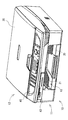
以下、本発明の好ましい実施形態について、添付図面を参照して説明する。図1は、本発明の一実施形態である複合機10の外観斜視図である。複合機10は、記録媒体の一例である記録用紙の両面に画像を記録可能なインクジェット方式のプリンタ部11を搭載し、記録用紙の表面に記録された画像を損傷させることなく、記録用紙の両面に画像を記録することができるものである。   Hereinafter, preferred embodiments of the present invention will be described with reference to the accompanying drawings. FIG. 1 is an external perspective view of a multifunction machine 10 according to an embodiment of the present invention. The multifunction machine 10 includes an inkjet printer unit 11 capable of recording an image on both sides of a recording sheet, which is an example of a recording medium, and does not damage the image recorded on the surface of the recording sheet. It is possible to record an image.

複合機10は、通話機能、ファクシミリ機能、プリンタ機能、スキャナ機能、及び、コピー機能などの各種の機能を有しており、プリンタ機能としては、記録用紙の両面に画像を記録する両面印刷機能を有している。   The multifunction machine 10 has various functions such as a telephone call function, a facsimile function, a printer function, a scanner function, and a copy function. The printer function includes a double-sided printing function for recording an image on both sides of a recording sheet. Have.

複合機10には、主に、下部に設けられるプリンタ部11と、上部に設けられるスキャナ部12と、正面上部に設けられる操作パネル40と、正面に設けられるスロット部43とが設けられている。   The multifunction machine 10 is mainly provided with a printer unit 11 provided in the lower part, a scanner part 12 provided in the upper part, an operation panel 40 provided in the upper part of the front, and a slot part 43 provided in the front. .

プリンタ部11は、正面に開口13が形成されており、この開口13から一部が露呈するようにして給紙トレイ20及び排紙トレイ21が上下2段に設けられている。給紙トレイ20は、記録用紙を積載するためのものである。この給紙トレイ20に積載された記録用紙は、プリンタ部11の内部へ給送され、所望の画像が記録された後に排紙トレイ21へ排出されるようになっている。   The printer unit 11 has an opening 13 formed in the front, and a paper feed tray 20 and a paper discharge tray 21 are provided in two upper and lower stages so that a part of the opening 13 is exposed. The paper feed tray 20 is for loading recording paper. The recording paper loaded on the paper feed tray 20 is fed into the printer unit 11 and is discharged to the paper discharge tray 21 after a desired image is recorded.

スキャナ部12は、いわゆるフラットベッドスキャナとして構成されている。原稿カバー30は、複合機10の天板として設けられており、その原稿カバー30の下には、図示しないプラテンガラスが配置されている。原稿は、プラテンガラス上に載置され、原稿カバー30に覆われた状態でスキャナ部12に読み取られる。   The scanner unit 12 is configured as a so-called flat bed scanner. The document cover 30 is provided as a top plate of the multifunction machine 10, and a platen glass (not shown) is disposed under the document cover 30. The document is placed on the platen glass and read by the scanner unit 12 while being covered with the document cover 30.

操作パネル40は、プリンタ部11やスキャナ部12を操作するためのものであって、各種操作ボタンや液晶表示部が設けられている。ユーザは、操作パネル40を操作することで、各種機能の設定や動作を実行することができる。例えば、記録媒体としての記録用紙の種類(普通紙又は葉書)の設定や、記録用紙の表面のみに画像を記録する片面記録モードの設定、表裏両面に画像を記録する両面記録モードの設定、解像度(ドラフトモード又はフォトモード)の設定を、操作パネル40を介して指示することができる。   The operation panel 40 is for operating the printer unit 11 and the scanner unit 12 and is provided with various operation buttons and a liquid crystal display unit. The user can set various functions and perform operations by operating the operation panel 40. For example, setting of the type of recording paper (plain paper or postcard) as a recording medium, setting of single-sided recording mode for recording an image only on the surface of the recording paper, setting of double-sided recording mode for recording an image on both front and back sides, resolution The setting of (draft mode or photo mode) can be instructed via the operation panel 40.

スロット部43は、記憶媒体である各種小型メモリカードが装填され得るように構成されている。例えば、スロット部43に小型メモリカードが装填された状態でユーザーが操作パネル40の操作を行うことにより、小型メモリカードに記憶された画像データを読み出し、その読み出した画像データを記録用紙に記録することができる。   The slot portion 43 is configured to be loaded with various small memory cards that are storage media. For example, when the user operates the operation panel 40 with the small memory card loaded in the slot unit 43, the image data stored in the small memory card is read, and the read image data is recorded on the recording paper. be able to.

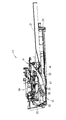
次に、図2を参照して、プリンタ部11の構成について概略する。図2は、プリンタ部11の構造を示す縦断面図である。プリンタ部11には、主に、記録用紙を搬送路23に給紙する給送部15と、給送部15から給紙される記録用紙を搬送する搬送路23と、搬送路23を介して搬送される記録用紙にインク滴を吐出することで記録用紙に画像を記録する記録部24と、記録用紙が排紙される排紙トレイ21と、排紙トレイ21と記録部24との間に配置され、裏面に画像を記録するために記録用紙の経路を切り換える経路切換部41と、経路切換部41により経路が切り換えられた記録用紙を、給送部15、搬送路23側に案内する反転案内部16とが設けられている。   Next, the configuration of the printer unit 11 will be outlined with reference to FIG. FIG. 2 is a longitudinal sectional view showing the structure of the printer unit 11. The printer unit 11 mainly includes a feeding unit 15 that feeds recording paper to the conveyance path 23, a conveyance path 23 that conveys recording paper fed from the feeding unit 15, and the conveyance path 23. A recording unit 24 that records an image on a recording sheet by ejecting ink droplets onto the conveyed recording sheet, a discharge tray 21 on which the recording sheet is discharged, and between the discharge tray 21 and the recording unit 24. A path switching unit 41 that is arranged and switches the path of the recording sheet to record an image on the back surface, and a reversal that guides the recording sheet whose path is switched by the path switching unit 41 to the feeding unit 15 and the conveyance path 23 side. A guide 16 is provided.

給送部15には、記録用紙を積載する給紙トレイ20が設けられている。給紙トレイ20は、プリンタ部11の底側に配置され、上面が開放された箱状に構成されている。給紙トレイ20に積載された記録用紙は、給紙ローラ25によって搬送路23に給紙される。   The feeding unit 15 is provided with a paper feed tray 20 on which recording paper is stacked. The paper feed tray 20 is disposed on the bottom side of the printer unit 11 and is configured in a box shape with an open top surface. The recording paper loaded on the paper feed tray 20 is fed to the transport path 23 by the paper feed roller 25.

そして、記録用紙の片面(表面)に画像を記録する場合には、給紙ローラ25によって給紙された記録用紙は、搬送路23に沿って下方から上方へUターンするように案内されて記録部24に至り、記録部24によって表面に画像が記録された後、排紙トレイ21に排出される。   When an image is recorded on one side (front surface) of the recording paper, the recording paper fed by the paper feed roller 25 is guided and recorded so as to make a U-turn from below to above along the transport path 23. The image is recorded on the surface by the recording unit 24 and then discharged to the paper discharge tray 21.

一方、記録用紙の両面(表裏面)に画像を記録する場合には、表面に画像が記録された記録用紙を、表面が給紙ローラ25に当接するように、経路切換部41によって反転案内部16へ案内し、給紙ローラ25によって再び搬送路23に給紙し、記録部24によって記録媒体の裏面に画像を記録した後、排紙トレイ21へ排紙される。   On the other hand, when images are recorded on both sides (front and back) of the recording paper, the reversing guide portion is arranged by the path switching portion 41 so that the recording paper with the image recorded on the front surface comes into contact with the paper feed roller 25. 16, the paper is fed again to the conveyance path 23 by the paper feed roller 25, and the image is recorded on the back surface of the recording medium by the recording unit 24, and then discharged to the paper discharge tray 21.

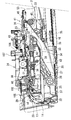
次に、図3を参照して、プリンタ部11の構成について詳細に説明する。図3は、プリンタ部11の部分拡大断面図である。   Next, the configuration of the printer unit 11 will be described in detail with reference to FIG. FIG. 3 is a partially enlarged sectional view of the printer unit 11.

給送部15には、給紙トレイ20の上側に、給紙ローラ25が配置されている。給紙ローラ25は、給紙トレイ20に積載された記録用紙を搬送路23へ給紙するものであり、給紙アーム26の先端に回転自在に軸支されている。給紙ローラ25は、LFモータ71(図9参照)を駆動源として動力伝達機構27を介して回転駆動される。この駆動伝達機構27は直線状に並ぶ複数のギアで構成されており、これらが噛合されることにより構成されている。   In the feeding unit 15, a paper feed roller 25 is disposed above the paper feed tray 20. The paper feed roller 25 feeds the recording paper loaded on the paper feed tray 20 to the transport path 23, and is rotatably supported at the tip of the paper feed arm 26. The paper feed roller 25 is rotationally driven via a power transmission mechanism 27 using an LF motor 71 (see FIG. 9) as a drive source. The drive transmission mechanism 27 includes a plurality of gears arranged in a straight line, and is configured by meshing them.

給紙アーム26は、その基端部が基軸28に支持されており、基軸28を回動中心軸として回転可能に構成されている。このため、給紙アーム26は、給紙トレイ20に対して接離可能に上下動することができる。また、給紙アーム26は、自重により又はバネ等に付勢されて下側へ回動付勢されている。このため、給紙アーム26は、通常において給紙トレイ20に接触し、給紙トレイ20が挿抜される際に上側へ退避するように構成されている。   The paper feed arm 26 has a base end portion supported by a base shaft 28 and is configured to be rotatable about the base shaft 28 as a rotation center axis. For this reason, the paper feed arm 26 can move up and down so as to be able to contact and separate from the paper feed tray 20. Further, the paper feed arm 26 is urged to rotate downward by its own weight or urged by a spring or the like. For this reason, the sheet feeding arm 26 is normally configured to come into contact with the sheet feeding tray 20 and retract upward when the sheet feeding tray 20 is inserted and removed.

給紙トレイ20から記録用紙を給紙する場合には、給紙アーム26が下側へ回動付勢され、給紙ローラ25が給紙トレイ20上の記録用紙に圧接された状態で、給紙ローラ25を回転し、給紙ローラ25のローラ面と記録用紙との間に発生する摩擦力により、最上位置の記録用紙が分離傾斜板22へ送り出される。   When feeding recording paper from the paper feed tray 20, the paper feed arm 26 is biased downward and the paper feed roller 25 is pressed against the recording paper on the paper feed tray 20. By rotating the paper roller 25, the uppermost recording paper is fed out to the separation inclined plate 22 by the frictional force generated between the roller surface of the paper feeding roller 25 and the recording paper.

そして、記録用紙の先端が分離傾斜板22に当接すると、この記録用紙は上方へ案内され、矢印14に沿って搬送路23へ送り込まれる。給紙ローラ25によって最上位置の記録用紙が送り出される際に、その直下の記録用紙が摩擦や静電気の作用によって共に送り出される場合もあるが、この記録用紙は分離傾斜板22との当接によって制止される。   When the leading edge of the recording sheet comes into contact with the separation inclined plate 22, the recording sheet is guided upward and sent to the conveyance path 23 along the arrow 14. When the uppermost recording paper is sent out by the paper feed roller 25, the recording paper immediately below it may be sent out together by friction or static electricity, but this recording paper is restrained by contact with the separation inclined plate 22. Is done.

搬送路23は、分離傾斜板22から上方へ向かった後、正面側へU字状に曲がって形成されており、複合機10の背面側(図3左側)から正面側(図3右側)へと延び、記録部24を経て排紙トレイ21へ通じている。   The conveyance path 23 is formed so as to be bent upward in a U-shape from the separation inclined plate 22 to the front side, and from the back side (left side in FIG. 3) to the front side (right side in FIG. 3). And extends to the paper discharge tray 21 via the recording unit 24.

搬送路23は、記録部24等が配設されている箇所以外では、外側ガイド面と内側ガイド面とによって区画形成されている。例えば、複合機10の背面側の搬送路23の湾曲部17は、外側ガイド部材18及び内側ガイド部材19が本体フレーム53に固定されることにより形成されている。この場合、外側ガイド部材18が外側ガイド面を形成し、内側ガイド部材19が内側ガイド面を形成する。また、外側ガイド部材18及び内側ガイド部材19は、所定間隔をあけて対向配置されている。   The conveyance path 23 is defined by an outer guide surface and an inner guide surface except for a portion where the recording unit 24 or the like is disposed. For example, the curved portion 17 of the conveyance path 23 on the back side of the multifunction machine 10 is formed by fixing the outer guide member 18 and the inner guide member 19 to the main body frame 53. In this case, the outer guide member 18 forms an outer guide surface, and the inner guide member 19 forms an inner guide surface. Moreover, the outer side guide member 18 and the inner side guide member 19 are opposingly arranged at predetermined intervals.

搬送路23が曲がっている箇所には、回転コロ29が設けられている。この回転コロ29は、回転自在に構成され、回転コロ29のローラ面は、外側ガイド面に露出されている。よって、搬送路23が曲がっている箇所においても、記録用紙が円滑に搬送される。   A rotating roller 29 is provided at a location where the conveyance path 23 is bent. The rotating roller 29 is configured to be rotatable, and the roller surface of the rotating roller 29 is exposed to the outer guide surface. Therefore, the recording paper is smoothly transported even at the portion where the transport path 23 is bent.

記録部24は、搬送路23の途中に配置されており、キャリッジ38及び記録ヘッド39とを備えている。記録ヘッド39は、キャリッジ38に搭載され、ガイドレール105、106に沿って主走査方向(図3紙面垂直方向)に往復動するように構成されている。   The recording unit 24 is disposed in the middle of the conveyance path 23 and includes a carriage 38 and a recording head 39. The recording head 39 is mounted on the carriage 38 and is configured to reciprocate along the guide rails 105 and 106 in the main scanning direction (the vertical direction in FIG. 3).

具体的には、キャリッジ38は、CRモータ95(図9参照)を駆動源とし、例えばベルト駆動機構を介してスライドされる。なお、複合機10の内部には、記録ヘッド39とは独立してインクカートリッジ(図示せず)が配置されている。このインクカートリッジからインクチューブを通じてインクが記録ヘッド39に供給される。そして、キャリッジ38が往復動される間に、記録ヘッド39からインクが微小なインク滴として吐出され、これにより、プラテン42上を搬送される記録用紙に画像が記録される。   Specifically, the carriage 38 is slid through a belt drive mechanism, for example, using a CR motor 95 (see FIG. 9) as a drive source. Note that an ink cartridge (not shown) is disposed inside the multi-function device 10 independently of the recording head 39. Ink is supplied from the ink cartridge to the recording head 39 through an ink tube. Then, while the carriage 38 is reciprocated, ink is ejected as fine ink droplets from the recording head 39, whereby an image is recorded on the recording paper conveyed on the platen 42.

複合機10の本体フレーム53には、キャリッジ38の位置を検出するリニアエンコーダ85(図9参照)が設けられている。このリニアエンコーダ85のエンコーダストリップがガイドレール105、106に配設されている。エンコーダストリップは、光を透過させる透光部及び光を遮断する遮光部を備えており、その透光部及び遮光部は、エンコーダストリップの長手方向に所定ピッチで交互に配置され所定のパターンを形成している。   The main body frame 53 of the multifunction machine 10 is provided with a linear encoder 85 (see FIG. 9) that detects the position of the carriage 38. An encoder strip of the linear encoder 85 is disposed on the guide rails 105 and 106. The encoder strip includes a light transmitting portion that transmits light and a light shielding portion that blocks light, and the light transmitting portion and the light shielding portion are alternately arranged at a predetermined pitch in the longitudinal direction of the encoder strip to form a predetermined pattern. doing.

また、キャリッジ38の上面には、透過型センサである光学センサ107が設けられている。この光学センサ107は、エンコーダストリップに対応する位置に設けられており、キャリッジ38と共にエンコーダストリップの長手方向に沿って往復動し、その往復動の際にエンコーダストリップのパターンを検出するものである。   An optical sensor 107 that is a transmissive sensor is provided on the upper surface of the carriage 38. The optical sensor 107 is provided at a position corresponding to the encoder strip, reciprocates along the longitudinal direction of the encoder strip together with the carriage 38, and detects the pattern of the encoder strip during the reciprocation.

さらに、キャリッジ38には、プラテン42上の記録用紙の存在の有無を検出するメディアセンサ86(図9参照)が設けられている。メディアセンサ86は、光源及び受光素子を備えており、光源から発せられた光は、プラテン42上に搬送された記録用紙に照射される一方、プラテン42上まで記録用紙が搬送されていない場合にはプラテン42に照射される。そして、記録用紙又はプラテン42に照射された光は反射され、その反射光を受光素子が受光しその受光量に応じた出力を行う。   Further, the carriage 38 is provided with a media sensor 86 (see FIG. 9) that detects the presence or absence of a recording sheet on the platen 42. The media sensor 86 includes a light source and a light receiving element, and light emitted from the light source is applied to the recording paper conveyed on the platen 42 while the recording paper is not conveyed to the platen 42. Is irradiated to the platen 42. Then, the light irradiated on the recording paper or the platen 42 is reflected, and the light receiving element receives the reflected light, and outputs according to the amount of light received.

記録部24よりも搬送路23の上流側には、搬送ローラ60及びピンチローラ31が設けられている。これらは対をなし、ピンチローラ31は、搬送ローラ60の下側に圧接するように配置されている。搬送ローラ60及びピンチローラ31は、搬送路23を搬送される記録用紙を狭持してプラテン42上へ送るものである。   A transport roller 60 and a pinch roller 31 are provided on the upstream side of the transport path 23 from the recording unit 24. These are paired, and the pinch roller 31 is disposed so as to be in pressure contact with the lower side of the conveying roller 60. The conveying roller 60 and the pinch roller 31 are for holding the recording paper conveyed through the conveying path 23 and feeding it onto the platen 42.

また、記録部24よりも搬送路23の下流側には、排紙ローラ62及び拍車ローラ63が設けられている。排紙ローラ62及び拍車ローラ63は、記録済みの記録用紙を狭持して搬送路23からさらに搬送方向下流側へ(排紙トレイ21側へ)搬送するものである。   Further, a discharge roller 62 and a spur roller 63 are provided on the downstream side of the conveyance path 23 from the recording unit 24. The paper discharge roller 62 and the spur roller 63 sandwich the recorded recording paper and transport it further from the transport path 23 to the downstream side in the transport direction (to the paper discharge tray 21 side).

搬送ローラ60及び排紙ローラ62は、LFモータ71を駆動源として駆動され、搬送ローラ60及び排紙ローラ62の駆動は同期しており、画像記録時に間欠駆動される。これにより、記録用紙は所定の改行幅で送られながら画像記録がなされる。   The transport roller 60 and the paper discharge roller 62 are driven using the LF motor 71 as a drive source, and the drive of the transport roller 60 and the paper discharge roller 62 are synchronized and are intermittently driven during image recording. As a result, the recording sheet is image-recorded while being sent with a predetermined line feed width.

なお、搬送ローラ60には、ロータリーエンコーダ87(図9参照)が設けられている。このロータリーエンコーダ87は、搬送ローラ60と共に回転するエンコーダディスク(図示せず)のパターンを光学センサで検出し、この光学センサが検出した信号に基づいて、搬送ローラ60及び排紙ローラ62の回転が制御される。また、画像記録の前後においては、搬送ローラ60及び排紙ローラ62は連続駆動され、迅速な用紙搬送が実現されている。   The transport roller 60 is provided with a rotary encoder 87 (see FIG. 9). The rotary encoder 87 detects a pattern of an encoder disk (not shown) that rotates together with the conveyance roller 60 with an optical sensor, and the rotation of the conveyance roller 60 and the discharge roller 62 is performed based on a signal detected by the optical sensor. Be controlled. In addition, before and after image recording, the transport roller 60 and the paper discharge roller 62 are continuously driven to realize rapid paper transport.

拍車ローラ63は、記録済みの記録用紙を圧接するものであり、記録用紙に記録された画像が劣化しないように、拍車ローラ63のローラ面には、拍車状に凹凸が形成されている。拍車ローラ63は、排紙ローラ62と接離する方向にスライド移動可能に設けられており、排紙ローラ62に圧接するように付勢されている。なお、拍車ローラ63を排紙ローラ62に付勢する手段は、典型的にはコイルバネが採用される。   The spur roller 63 presses the recorded recording paper, and the spur roller 63 has a spur-like unevenness on the roller surface so that the image recorded on the recording paper does not deteriorate. The spur roller 63 is provided so as to be slidable in a direction in which the spur roller 63 is in contact with and separated from the paper discharge roller 62, and is urged so as to be in pressure contact with the paper discharge roller 62. As a means for urging the spur roller 63 against the paper discharge roller 62, a coil spring is typically employed.

図3では図示されていないが、本実施形態では、複数の拍車ローラ63が備えられており、各拍車ローラ63は、記録用紙の搬送方向と直交する方向、すなわち記録用紙の幅方向に均等に並設されている。拍車ローラ63の数は特に限定されるものではないが、本実施形態では8個に設定されている。   Although not shown in FIG. 3, in the present embodiment, a plurality of spur rollers 63 are provided, and each spur roller 63 is equally in the direction orthogonal to the recording paper conveyance direction, that is, the width direction of the recording paper. It is installed side by side. The number of spur rollers 63 is not particularly limited, but is set to 8 in this embodiment.

排紙ローラ62と拍車ローラ63との間に記録用紙が進入すると、拍車ローラ63は、記録用紙の厚み分だけコイルバネの付勢力に抗して退避する。記録用紙は排紙ローラ62に圧接され、排紙ローラ62の回転力が確実に記録用紙へ伝達される。また、ピンチローラ31も搬送ローラ60に対して同様に弾性付勢されている。したがって、記録用紙は、搬送ローラ60に圧接され、搬送ローラ60の回転力が確実に記録用紙へ伝達される。   When the recording paper enters between the paper discharge roller 62 and the spur roller 63, the spur roller 63 retracts against the biasing force of the coil spring by the thickness of the recording paper. The recording paper is pressed against the paper discharge roller 62, and the rotational force of the paper discharge roller 62 is reliably transmitted to the recording paper. Similarly, the pinch roller 31 is also elastically biased with respect to the conveying roller 60. Therefore, the recording sheet is pressed against the conveying roller 60, and the rotational force of the conveying roller 60 is reliably transmitted to the recording sheet.

搬送路23の搬送ローラ60よりも上流側には、レジセンサ102(図9参照)が設けられている。このレジセンサ102は、検出子及び光学センサを備えており、検出子は、搬送路23を横切るように配置され、搬送路23に出没可能である。検出子は、常時搬送路23に突出するように弾性付勢されており、搬送路23を搬送される記録用紙が検出子に当接することにより、検出子が搬送路23へ没入する。検出子の出没により、上記光学センサがON又はOFFされる。したがって、記録用紙が検出子を出没させることによって、搬送路23における記録用紙の先端又は後端の位置が検出される。   A registration sensor 102 (see FIG. 9) is provided on the upstream side of the transport path 23 from the transport roller 60. The registration sensor 102 includes a detector and an optical sensor. The detector is arranged so as to cross the transport path 23 and can appear and disappear in the transport path 23. The detector is elastically biased so as to always protrude into the transport path 23, and the detector is immersed in the transport path 23 when the recording paper transported through the transport path 23 contacts the detector. The optical sensor is turned on or off by the appearance of the detector. Therefore, the position of the leading edge or the trailing edge of the recording paper in the transport path 23 is detected by causing the recording paper to make the detector appear and disappear.

次に、図4及び図5を参照して、経路切換部41について説明する。図4及び図5は、経路切換部周辺を拡大して示す拡大断面図であり、図5は、図4に示す状態の経路切換部41が、中心軸52を回転中心として回動した状態を示している。   Next, the route switching unit 41 will be described with reference to FIGS. 4 and 5. 4 and 5 are enlarged sectional views showing the periphery of the route switching unit in an enlarged manner. FIG. 5 shows a state in which the route switching unit 41 in the state shown in FIG. 4 is rotated about the central axis 52 as a rotation center. Show.

経路切換部41は、記録部24よりも下流側に配置されている。具体的には、経路切換部41は、記録部24よりも搬送路23の下流側部位36、すなわち搬送路23と反転案内部16との境界部分における搬送方向下流側に配置されている。経路切換部41には、ローラ対を構成する第1ローラ45及び第2ローラ46と、第2ローラ46に並設された補助ローラ47とが設けられている。   The path switching unit 41 is disposed on the downstream side of the recording unit 24. Specifically, the path switching unit 41 is disposed downstream of the recording unit 24 in the downstream portion 36 of the transport path 23, that is, on the downstream side in the transport direction at the boundary portion between the transport path 23 and the reverse guide unit 16. The path switching unit 41 is provided with a first roller 45 and a second roller 46 constituting a roller pair, and an auxiliary roller 47 arranged in parallel with the second roller 46.

第1ローラ45及び第2ローラ46は、排紙ローラ62及び拍車ローラ63から送られた記録用紙103を狭持するものである。第1ローラ45及び第2ローラ46は、記録用紙103を搬送路23に沿ってさらに搬送方向下流側へ(排紙トレイ21側へ)搬送可能であると共に、記録用紙を反転案内部16に搬送可能である。   The first roller 45 and the second roller 46 sandwich the recording paper 103 sent from the paper discharge roller 62 and the spur roller 63. The first roller 45 and the second roller 46 can transport the recording paper 103 along the transport path 23 further downstream in the transport direction (to the paper discharge tray 21 side) and transport the recording paper to the reversal guide unit 16. Is possible.

第2ローラ46及び補助ローラ47は、フレーム48に取り付けられている。このフレーム48は、複合機10の左右方向(図3の紙面垂直方向)に延びている(図6参照)。フレーム48の断面形状は、略L字状に形成されており、これにより、フレーム48の所要の曲げ剛性が確保されている。   The second roller 46 and the auxiliary roller 47 are attached to the frame 48. The frame 48 extends in the left-right direction of the multi-function device 10 (the direction perpendicular to the plane of FIG. 3) (see FIG. 6). The cross-sectional shape of the frame 48 is formed in a substantially L shape, thereby ensuring the required bending rigidity of the frame 48.

フレーム48は、一体化された8つのサブフレーム49を備えている(図6参照)。各サブフレーム49は、複合機10の中心を基準として上記左右方向に対称に配置されている。各サブフレーム49は、それぞれ一つの第2ローラ46及び補助ローラ47を軸支している。従って、フレーム48は、それぞれ8つの第2ローラ46及び補助ローラ47を備えていることになり、各第2ローラ46及び補助ローラ47は、記録用紙の搬送方向と直交する方向、すなわち記録用紙103の幅方向に均等に並設されている。   The frame 48 includes eight integrated subframes 49 (see FIG. 6). Each sub-frame 49 is symmetrically arranged in the left-right direction with respect to the center of the multifunction machine 10. Each subframe 49 pivotally supports one second roller 46 and auxiliary roller 47. Therefore, each frame 48 includes eight second rollers 46 and auxiliary rollers 47, and each second roller 46 and auxiliary roller 47 has a direction orthogonal to the recording sheet conveyance direction, that is, the recording sheet 103. Are arranged in parallel in the width direction.

第2ローラ46及び補助ローラ47は、各サブフレーム49に設けられた支持軸50、51に軸支され、その支持軸50、51の回りに回転自在に構成されている。本実施形態では、第2ローラ46及び補助ローラ47は、拍車状に形成されている。補助ローラ47は、第2ローラ46よりも所定距離だけ搬送方向上流側に配置されている。各第2ローラ46は、図示しないバネにより下方に付勢されており、常に第1ローラ45に弾性的に押し付けられている。   The second roller 46 and the auxiliary roller 47 are pivotally supported by support shafts 50 and 51 provided in each sub-frame 49 and are configured to be rotatable around the support shafts 50 and 51. In the present embodiment, the second roller 46 and the auxiliary roller 47 are formed in a spur shape. The auxiliary roller 47 is disposed upstream of the second roller 46 by a predetermined distance in the transport direction. Each second roller 46 is urged downward by a spring (not shown) and is always elastically pressed against the first roller 45.

第1ローラ45は、所要の駆動伝達機構を介してLFモータ71と連結されており、そのLFモータ71を駆動源として回転駆動される。また、第1ローラ45は、中心軸52を備えており、その中心軸52は、複合機10の本体フレーム53側に支持されている。   The first roller 45 is connected to the LF motor 71 via a required drive transmission mechanism, and is driven to rotate using the LF motor 71 as a drive source. The first roller 45 includes a central shaft 52, and the central shaft 52 is supported on the main body frame 53 side of the multifunction machine 10.

第1ローラ45の上方には、第2ローラ46が載置されている。第1ローラ45は、単一の細長円柱状に形成されていてもよく、また、8つのローラがそれぞれ各第2ローラ46と対向配置されていてもよい。   A second roller 46 is placed above the first roller 45. The first roller 45 may be formed in a single elongated cylindrical shape, and eight rollers may be arranged to face the second rollers 46, respectively.

なお、第1ローラ45は、LFモータ71によって正転及び逆転され、記録用紙を排紙トレイ21側および反転案内部16側に搬送可能に構成されている。即ち、搬送路23に沿って搬送された記録用紙103は、第1ローラ45と第2ローラ46とによって挟持される。そして、第1ローラ45が正転すると、記録用紙103は第1ローラ45と第2ローラ46とによって挟持されたまま搬送方向下流側へ搬送され、排紙トレイ21に排出される。他方、第1ローラ45が逆転すると、記録用紙は第1ローラ45と第2ローラ46とによって挟持されたまま搬送方向上流側へ戻される。   The first roller 45 is configured to be forwardly and reversely rotated by the LF motor 71 so that the recording sheet can be conveyed to the discharge tray 21 side and the reverse guide unit 16 side. That is, the recording sheet 103 conveyed along the conveyance path 23 is sandwiched between the first roller 45 and the second roller 46. When the first roller 45 rotates forward, the recording sheet 103 is conveyed downstream in the conveying direction while being sandwiched between the first roller 45 and the second roller 46 and is discharged to the paper discharge tray 21. On the other hand, when the first roller 45 rotates in the reverse direction, the recording sheet is returned to the upstream side in the transport direction while being sandwiched between the first roller 45 and the second roller 46.

本実施形態では、第1ローラ45の外径は、排紙ローラ62の外径よりも若干大きく設定されている。すなわち、両者が同回転速度で駆動された場合は、第1ローラ45の周速度の方が排紙ローラ62の周速度よりも大きくなる。そのため、記録用紙103が排紙ローラ62及び第1ローラ45の双方によって搬送されるときは、記録用紙103は常に搬送方向に引っ張られるようになっている。   In the present embodiment, the outer diameter of the first roller 45 is set slightly larger than the outer diameter of the paper discharge roller 62. That is, when both are driven at the same rotational speed, the peripheral speed of the first roller 45 is larger than the peripheral speed of the paper discharge roller 62. Therefore, when the recording paper 103 is conveyed by both the paper discharge roller 62 and the first roller 45, the recording paper 103 is always pulled in the conveyance direction.

ここで、図6乃至図8を参照して、上述したように構成された経路切換部41の駆動機構44について説明する。図6は、経路切換部41の斜視図である。図7は、図6に示す矢印VII方向矢視図である。図8は、図6に示す矢印VIII方向矢視図である。駆動機構44は、経路切換部41を図4に示す状態から図5に示す状態に駆動したり、図5に示す状態から図4に示す状態に復帰駆動させるためのものである。   Here, the drive mechanism 44 of the path switching unit 41 configured as described above will be described with reference to FIGS. FIG. 6 is a perspective view of the path switching unit 41. FIG. 7 is a view in the direction of arrow VII shown in FIG. 8 is a view taken in the direction of arrow VIII shown in FIG. The drive mechanism 44 is for driving the path switching unit 41 from the state shown in FIG. 4 to the state shown in FIG. 5 or for returning from the state shown in FIG. 5 to the state shown in FIG.

図6に示すように、駆動機構44には、中心軸52に設けられた従動ギア54と、これと噛み合う駆動ギア55と、駆動ギア55と連結されたカム57とが設けられている。   As shown in FIG. 6, the drive mechanism 44 includes a driven gear 54 provided on the central shaft 52, a drive gear 55 that meshes with the driven gear 54, and a cam 57 that is connected to the drive gear 55.

カム57は、回転駆動軸58の一端に連結されており、回転駆動軸58は、LFモータ71を駆動源として駆動される。図8に示すように、カム57には案内溝59が設けられている。この案内溝59は、回転駆動軸58の回りに環状に形成されている。具体的には、案内溝59には、回転駆動軸58を中心とする小円弧部69及び大円弧部70と、小円弧部69の一端及び大円弧部70の一端を連結する連結溝72と、小円弧部69の他端及び大円弧部70の他端を連結する連結溝73とが設けられている。   The cam 57 is connected to one end of a rotation drive shaft 58, and the rotation drive shaft 58 is driven using the LF motor 71 as a drive source. As shown in FIG. 8, the cam 57 is provided with a guide groove 59. The guide groove 59 is formed in an annular shape around the rotation drive shaft 58. Specifically, the guide groove 59 includes a small arc portion 69 and a large arc portion 70 centered on the rotation drive shaft 58, and a connection groove 72 that connects one end of the small arc portion 69 and one end of the large arc portion 70. A connecting groove 73 that connects the other end of the small arc portion 69 and the other end of the large arc portion 70 is provided.

図6及び図7に示すように、従動ギア54は、歯部64とフランジ部65とから構成されている。歯部64は、中心軸52を中心とするインボリュート歯車として構成されている。歯部64は、中心軸52に嵌め込まれ、中心軸52の回りに回転することができるようになっている。また、フランジ部65は、歯部64と一体的に形成されており、フレーム48と連結されている。したがって、歯部64が回転すると、中心軸52を回転中心としてフレーム48、サブフレーム49、第2ローラ46及び補助ローラ47が一体的に回転するようになっている。   As shown in FIGS. 6 and 7, the driven gear 54 includes a tooth portion 64 and a flange portion 65. The tooth portion 64 is configured as an involute gear centered on the central shaft 52. The tooth portion 64 is fitted into the central shaft 52 and can rotate around the central shaft 52. The flange portion 65 is formed integrally with the tooth portion 64 and is connected to the frame 48. Therefore, when the tooth portion 64 rotates, the frame 48, the sub frame 49, the second roller 46, and the auxiliary roller 47 rotate integrally with the central shaft 52 as the rotation center.

駆動ギア55は、支持軸66に回動自在に支持されている。この支持軸66は、本体フレーム53に設けられている。駆動ギア55は、歯部67とアーム68とによって構成されている。歯部67は、上記支持軸66を中心とするインボリュート歯車として構成されており、上記歯部64と噛み合っている。アーム68には、図8に示すピン56が突設されており、ピン56は、案内溝59に嵌合しており、案内溝59に沿ってスライド自在となっている。そして、歯部67が回転することにより歯部64が回転し、その結果、中心軸52を回転中心としてフレーム48、サブフレーム49、第2ローラ46及び補助ローラ47が一体的に回転する。   The drive gear 55 is rotatably supported on the support shaft 66. The support shaft 66 is provided on the main body frame 53. The drive gear 55 includes a tooth portion 67 and an arm 68. The tooth portion 67 is configured as an involute gear centered on the support shaft 66 and meshes with the tooth portion 64. A pin 56 shown in FIG. 8 protrudes from the arm 68, and the pin 56 is fitted in the guide groove 59 and is slidable along the guide groove 59. Then, when the tooth portion 67 rotates, the tooth portion 64 rotates, and as a result, the frame 48, the sub-frame 49, the second roller 46, and the auxiliary roller 47 rotate integrally around the center shaft 52 as a rotation center.

図8が示すように、カム57が回転すると、ピン56は案内溝59に沿って相対的に移動し、特に、連結溝72、73に沿ってスライドするときは、ピン56は、カム57の径方向に移動することになる。このため、図8においてカム57が時計回り(矢印82の方向)に回転されたときは、ピン56が大円弧部70、連結溝72及び小円弧部69に順に移動する。   As shown in FIG. 8, when the cam 57 rotates, the pin 56 moves relatively along the guide groove 59, and particularly when sliding along the connecting grooves 72, 73, the pin 56 moves toward the cam 57. It will move in the radial direction. For this reason, when the cam 57 is rotated clockwise (in the direction of the arrow 82) in FIG. 8, the pin 56 sequentially moves to the large arc portion 70, the connecting groove 72, and the small arc portion 69.

従って、駆動ギア55は、図7において時計回りに回転する。その結果、従動ギア54は、図7において中心軸52を中心として反時計回りに回転する。前述のように、従動ギア54はフレーム48と連結されているから、従動ギア54が回転することにより、中心軸52を回転中心としてフレーム48、サブフレーム49、第1ローラ46及び補助ローラ47が一体的に回転する。尚、この状態から上述したのとはカム57が逆回転すれば、当然に、中心軸52を回転中心としてフレーム48、サブフレーム49、第1ローラ46及び補助ローラ47が一体的に回転して、元の状態に復帰する。   Accordingly, the drive gear 55 rotates clockwise in FIG. As a result, the driven gear 54 rotates counterclockwise around the central axis 52 in FIG. As described above, since the driven gear 54 is connected to the frame 48, the rotation of the driven gear 54 causes the frame 48, the sub frame 49, the first roller 46, and the auxiliary roller 47 to rotate around the central shaft 52. Rotates integrally. From this state, if the cam 57 rotates in the reverse direction as described above, the frame 48, the sub-frame 49, the first roller 46, and the auxiliary roller 47 rotate as a whole with the central shaft 52 as the center of rotation. , Return to the original state.

本実施形態において、図4が示すような経路切換部41の姿勢を「被記録媒体排出姿勢」、図5が示すような経路切換部41の姿勢を「被記録媒体反転姿勢」とすれば、記録用紙の表面にのみ画像が記録される場合(片面記録)には、経路切換部41が常時被記録媒体排出姿勢となり、搬送路23に沿って搬送される記録用紙は、そのまま排紙トレイ21側へ送られる(図4参照)。   In this embodiment, when the posture of the path switching unit 41 as shown in FIG. 4 is “recording medium discharge posture” and the posture of the path switching unit 41 as shown in FIG. When an image is recorded only on the surface of the recording sheet (single-sided recording), the path switching unit 41 is always in the recording medium discharge posture, and the recording sheet conveyed along the conveyance path 23 is left as it is. (See FIG. 4).

一方、経路切換部41が被記録媒体反転姿勢に変化したときは、図5に示すように、記録用紙103を反転案内部16へ案内されるようになっている。具体的には、記録用紙の表裏両面に画像が記録される場合、まず、経路切換部41が被記録媒体排出姿勢を維持し(図4参照)、表面に画像記録された記録用紙が搬送方向下流側へ送られる。その後、経路切換部41が被記録媒体排出姿勢(図4参照)から被記録媒体反転姿勢(図5参照)に変化し、補助ローラ47が記録用紙103を押さえつけて反転案内部16側へ案内する。   On the other hand, when the path switching unit 41 changes to the recording medium reversal posture, the recording paper 103 is guided to the reversal guide unit 16 as shown in FIG. Specifically, when images are recorded on both the front and back sides of the recording paper, first, the path switching unit 41 maintains the recording medium ejection posture (see FIG. 4), and the recording paper on which the image is recorded is transported in the transport direction. Sent downstream. Thereafter, the path switching unit 41 changes from the recording medium discharge posture (see FIG. 4) to the recording medium reverse posture (see FIG. 5), and the auxiliary roller 47 presses the recording paper 103 and guides it to the reverse guiding unit 16 side. .

再び、図4に戻り、説明を続ける。上述したように構成された経路切換部41の下流側には、ガイド部76が配置されている。ガイド部76は、第1ローラ45及び第2ローラ46よりも搬送方向下流側に設けられている。本体フレーム53に支持板75が取り付けられており、この支持板75にガイド部76が設けられている。   Returning again to FIG. 4, the description will be continued. A guide unit 76 is disposed on the downstream side of the path switching unit 41 configured as described above. The guide portion 76 is provided on the downstream side in the transport direction with respect to the first roller 45 and the second roller 46. A support plate 75 is attached to the main body frame 53, and a guide portion 76 is provided on the support plate 75.

このガイド部76には、支持板75の下面に固定された基部77と、基部77に支持されたガイドローラ78とが設けられている。基部77は支軸79を備えており、ガイドローラ78は、この支軸79に回転自在に軸支されている。なお、本実施形態では、このガイドローラ78は拍車状に形成されている。   The guide portion 76 is provided with a base portion 77 fixed to the lower surface of the support plate 75 and a guide roller 78 supported by the base portion 77. The base 77 includes a support shaft 79, and the guide roller 78 is rotatably supported by the support shaft 79. In the present embodiment, the guide roller 78 is formed in a spur shape.

このガイド部76は、上記第1ローラ45及び第2ローラ46が逆転して記録用紙103が反転案内部16へ送られているときに記録用紙103の記録面に接触する。また、ガイド部76は、第1ローラ45及び第2ローラ46が正転して記録用紙103が反転案内部16へ送られているときは、記録用紙103に接触しない。具体的には、ガイド部76は、第1ローラ45及び第2ローラ46の接点と、排紙ローラ62及び拍車ローラ63の接点とを結ぶ仮想線と接触しない位置に設けられている。   The guide unit 76 contacts the recording surface of the recording sheet 103 when the first roller 45 and the second roller 46 are rotated in the reverse direction and the recording sheet 103 is sent to the reverse guiding unit 16. Further, the guide unit 76 does not contact the recording sheet 103 when the first roller 45 and the second roller 46 are rotated forward and the recording sheet 103 is sent to the reverse guide unit 16. Specifically, the guide portion 76 is provided at a position where it does not come into contact with an imaginary line connecting the contact point between the first roller 45 and the second roller 46 and the contact point between the paper discharge roller 62 and the spur roller 63.

記録用紙103が搬送方向の向きを変えて反転案内部16に送られる場合には、記録用紙103のうち第1ローラ45及び第2ローラ46よりも下流側の部分は、記録用紙103の剛性によって反転案内部16と平行な方向に向きが変えるよう作用する。しかし、ガイドローラ78が記録用紙103の記録面に当接し、この記録用紙103を撓ませる。これにより、記録用紙103は、第1ローラ45及び第2ローラ46に巻き付けられるため、安定した搬送力を得ることができ、記録用紙103は、確実に反転案内部16に送られる。   When the recording paper 103 is sent to the reversing guide unit 16 while changing the direction of the conveyance direction, a portion of the recording paper 103 downstream of the first roller 45 and the second roller 46 is caused by the rigidity of the recording paper 103. It acts to change the direction in a direction parallel to the reversing guide portion 16. However, the guide roller 78 comes into contact with the recording surface of the recording paper 103 and bends the recording paper 103. Accordingly, since the recording paper 103 is wound around the first roller 45 and the second roller 46, a stable conveying force can be obtained, and the recording paper 103 is surely sent to the reverse guide unit 16.

再び、図3に戻って説明を続ける。反転案内部16は、搬送路23に接続されており、記録部24よりも搬送路23の下流側部位36に連続している。反転案内部16は、表面に画像が記録された記録用紙を再び給紙トレイ20上に導く反転経路を構成している。この反転経路は、第1ガイド面32と第2ガイド面33とによって区画形成されている。   Returning again to FIG. 3, the description will be continued. The reversing guide unit 16 is connected to the conveyance path 23 and is continuous to the downstream portion 36 of the conveyance path 23 relative to the recording unit 24. The reversing guide unit 16 constitutes a reversing path that guides the recording paper having an image recorded on the surface thereof onto the paper feed tray 20 again. This inversion path is defined by the first guide surface 32 and the second guide surface 33.

本実施形態では、第1ガイド面32及び第2ガイド面33は、それぞれ、複合機10の本体フレーム53の内部に配置されたガイド部材34及びガイド部材35の表面により形成されている。各ガイド部材34、35は、所定間隔をあけて対向配置されており、第1ガイド面32及び第2ガイド面33は、搬送路23の下流側部位36から給紙ローラ25の方へ斜め下方に延びている。   In the present embodiment, the first guide surface 32 and the second guide surface 33 are formed by the surfaces of the guide member 34 and the guide member 35 disposed inside the main body frame 53 of the multifunction machine 10, respectively. The guide members 34 and 35 are arranged to face each other at a predetermined interval, and the first guide surface 32 and the second guide surface 33 are obliquely downward from the downstream portion 36 of the transport path 23 toward the paper feed roller 25. It extends to.

なお、本実施形態では、反転案内部16は、記録用紙を給紙トレイ20上に戻すように構成されているが、これに限定されるものではない。反転案内部16は、要するに搬送路23の下流側部位36と上流側部位37とを接続することができれば十分であり、したがって、記録用紙は、上流側部位37よりも給紙トレイ20側に戻されればよい。   In the present embodiment, the reversing guide unit 16 is configured to return the recording paper onto the paper feed tray 20, but is not limited thereto. In short, it is sufficient for the reversing guide unit 16 to be able to connect the downstream side portion 36 and the upstream side portion 37 of the conveyance path 23, and therefore, the recording paper returns to the paper feed tray 20 side from the upstream side portion 37. It only has to be done.

次に、図9を参照して、複合機10の制御部84の構成について説明する。図9は、複合機10の制御部84の構成を示すブロック図である。制御部84は、プリンタ部11のみでなくスキャナ部12も含む複合機10の全体動作を制御するものであるが、スキャナ部12についての詳細な説明は省略する。   Next, the configuration of the control unit 84 of the multifunction machine 10 will be described with reference to FIG. FIG. 9 is a block diagram illustrating a configuration of the control unit 84 of the multifunction machine 10. The control unit 84 controls the overall operation of the multifunction machine 10 including not only the printer unit 11 but also the scanner unit 12, but detailed description of the scanner unit 12 is omitted.

制御部84は、図に示すように、CPU(Central Processing Unit)88、ROM(Read Only Memory)89、RAM(Random Access Memory)90、電源オフ後も保持すべき設定やフラグ等が格納されるEEPROM(Electrically Erasable and Programmable ROM)91を主とするマイクロコンピュータとして構成されており、バス92を介してASIC(Application Specific Integrated Circuit)93に接続されている。   As shown in the figure, the control unit 84 stores a CPU (Central Processing Unit) 88, a ROM (Read Only Memory) 89, a RAM (Random Access Memory) 90, settings and flags to be retained even after the power is turned off. An EEPROM (Electrically Erasable and Programmable ROM) 91 is configured as a main microcomputer, and is connected to an ASIC (Application Specific Integrated Circuit) 93 via a bus 92.

ROM89には、複合機10の各種動作を制御するためのプログラム等が格納されている。例えば、図10に示す印刷処理を実行させる印刷処理プログラム89aが格納されている。RAM90は、CPU88が上記プログラムを実行する際に用いる各種データを一時的に記録する記憶領域又は作業領域として使用される。   The ROM 89 stores a program for controlling various operations of the multifunction machine 10. For example, a print processing program 89a for executing the print processing shown in FIG. 10 is stored. The RAM 90 is used as a storage area or a work area for temporarily recording various data used when the CPU 88 executes the program.

ASIC93は、CPU88からの指令に従い、LFモータ71に通電する相励磁信号等を生成して、該信号をLFモータ71の駆動回路94に付与し、該駆動回路94を介して駆動信号をLFモータ71に通電することにより、LFモータ71の回転制御を行っている。   The ASIC 93 generates a phase excitation signal and the like for energizing the LF motor 71 in accordance with a command from the CPU 88, applies the signal to the drive circuit 94 of the LF motor 71, and sends the drive signal to the LF motor via the drive circuit 94. The rotation of the LF motor 71 is controlled by energizing the 71.

駆動回路94は、給紙ローラ25、搬送ローラ60、排紙ローラ62、第1ローラ45などに接続されたLFモータ71を駆動させるものであり、ASIC93からの出力信号を受けて、LFモータ71を回転するための電気信号を生成する。該電気信号を受けてLFモータ71が回転し、該LFモータ71の回転力がギアや駆動軸等からなる周知の駆動機構を介して、給紙ローラ25、搬送ローラ60、排紙ローラ62、第1ローラ45へ伝達される。   The drive circuit 94 drives the LF motor 71 connected to the paper feed roller 25, the transport roller 60, the paper discharge roller 62, the first roller 45, etc., and receives the output signal from the ASIC 93 and receives the LF motor 71. An electric signal for rotating the is generated. In response to the electrical signal, the LF motor 71 rotates, and the rotational force of the LF motor 71 is fed via a known drive mechanism including a gear, a drive shaft, and the like, through the paper feed roller 25, the transport roller 60, the paper discharge roller 62, It is transmitted to the first roller 45.

この複合機10では、LFモータ71は、給紙トレイ20からの記録用紙の給紙のための駆動源となっており、また、プラテン42上に位置する記録用紙の搬送や記録済みの記録用紙を排紙トレイ21へ排出するための駆動源となっており、更には、所定の動力伝達機構を介して排紙ローラ62を駆動する駆動源にもなっている。   In this multifunction device 10, the LF motor 71 serves as a drive source for feeding recording paper from the paper feed tray 20, and transports recording paper that is positioned on the platen 42 and has already been recorded. Is a drive source for discharging the paper to the paper discharge tray 21, and further, a drive source for driving the paper discharge roller 62 via a predetermined power transmission mechanism.

即ち、LFモータ71は、搬送ローラ60と、駆動伝達機構27を介して給紙ローラ25と、所定の動力伝達機構を介して排紙ローラ62とを駆動する。なお、所定の動力伝達機構は、例えば歯車列により構成してもよいし、組付スペースの関係上、タイミングベルト等を使用してもよい。   That is, the LF motor 71 drives the conveyance roller 60, the paper feed roller 25 via the drive transmission mechanism 27, and the paper discharge roller 62 via the predetermined power transmission mechanism. The predetermined power transmission mechanism may be constituted by a gear train, for example, or a timing belt or the like may be used due to the assembly space.

また、ASIC93は、CPU88からの指令に従い、CR(キャリッジ)モータ95に通電する相励磁信号等を生成して、該信号をCRモータ95の駆動回路96に付与し、該駆動回路96を介して駆動信号をCRモータ95に通電することにより、CRモータ95の回転制御を行っている。   Further, the ASIC 93 generates a phase excitation signal and the like for energizing a CR (carriage) motor 95 in accordance with a command from the CPU 88, gives the signal to the drive circuit 96 of the CR motor 95, and passes through the drive circuit 96. The CR motor 95 is controlled to rotate by energizing the CR motor 95 with a drive signal.

駆動回路96は、上記キャリッジ38に接続されたCRモータ95を駆動させるものであり、ASIC93からの出力信号を受けて、CRモータ95を回転するための電気信号を生成する。該電気信号を受けてCRモータ95が回転し、該CRモータ95の回転力がキャリッジ38へ伝達されことによりキャリッジ38が往復動される。   The drive circuit 96 drives the CR motor 95 connected to the carriage 38, receives an output signal from the ASIC 93, and generates an electrical signal for rotating the CR motor 95. Upon receipt of the electrical signal, the CR motor 95 rotates, and the rotational force of the CR motor 95 is transmitted to the carriage 38, whereby the carriage 38 is reciprocated.

駆動回路97は、記録ヘッド39から所定のタイミングでインクを記録用紙103に対して選択的に吐出させるものであり、CPU88から出力される駆動制御手順に基づいてASIC93において生成された出力信号を受け、記録ヘッド39を駆動制御する。   The driving circuit 97 selectively ejects ink from the recording head 39 to the recording paper 103 at a predetermined timing, and receives an output signal generated by the ASIC 93 based on a driving control procedure output from the CPU 88. The drive of the recording head 39 is controlled.

ASIC93には、スキャナ部12や、複合機10の操作指示を行うための操作パネル40、各種小型メモリカードが挿入されるスロット部43、パソコン等の外部機器とパラレルケーブルやUSBケーブルを介してデータの送受信を行うためのパラレルインタフェース(I/F)98及びUSBインタフェース(I/F)99、ファクシミリ機能を実現するためのNCU(Network Control Unit)100やモデム(MODEM)101が接続されている。   The ASIC 93 includes a scanner unit 12, an operation panel 40 for instructing operation of the multifunction device 10, a slot unit 43 into which various small memory cards are inserted, an external device such as a personal computer, and data via a parallel cable or a USB cable. Are connected to a parallel interface (I / F) 98 and a USB interface (I / F) 99 for transmitting and receiving, an NCU (Network Control Unit) 100 and a modem (MODEM) 101 for realizing a facsimile function.

その他、ASIC93には、給紙ローラ25から搬送ローラ60近傍に記録用紙103が搬送されたことを検出するレジセンサ102、LFモータ71により駆動された各ローラの回転量を検出するロータリエンコーダ87、キャリッジ38の移動量を検出するためのリニアエンコーダ85、プラテン42上の記録用紙103の存在の有無を検出するメディアセンサ86が接続されている。   In addition, the ASIC 93 includes a registration sensor 102 that detects that the recording sheet 103 has been transported from the paper feed roller 25 to the vicinity of the transport roller 60, a rotary encoder 87 that detects the amount of rotation of each roller driven by the LF motor 71, and a carriage. A linear encoder 85 for detecting the amount of movement 38 and a media sensor 86 for detecting the presence or absence of the recording paper 103 on the platen 42 are connected.

ここで、複合機10の制御部84で行われる処理を簡単に説明する。複合機10の電源がオンされると、キャリッジ38は、一旦そのスライド端まで移動され、リニアエンコーダ85による検出位置が初期化される。キャリッジ38が初期位置からスライド移動すると、キャリッジ38に設けられた光学センサ107がエンコーダストリップのパターンを検出する。   Here, a process performed by the control unit 84 of the multifunction machine 10 will be briefly described. When the power of the multifunction machine 10 is turned on, the carriage 38 is once moved to its slide end, and the detection position by the linear encoder 85 is initialized. When the carriage 38 slides from the initial position, the optical sensor 107 provided on the carriage 38 detects the encoder strip pattern.

制御部84は、光学センサ107の検出に基づくパルス信号数によって、キャリッジ38の移動量を把握し、この移動量に基づいてキャリッジ38の往復動を制御すべく、CRモータ95の回転を制御する。また、制御部84は、レジセンサ102の出力信号及びロータリーエンコーダ87が検出するエンコーダ量に基づいて記録用紙103の先端又は後端の位置並びに記録用紙103の搬送量を把握する。   The control unit 84 grasps the movement amount of the carriage 38 based on the number of pulse signals based on the detection of the optical sensor 107, and controls the rotation of the CR motor 95 to control the reciprocation of the carriage 38 based on the movement amount. . Further, the control unit 84 grasps the position of the leading or trailing end of the recording paper 103 and the transport amount of the recording paper 103 based on the output signal of the registration sensor 102 and the encoder amount detected by the rotary encoder 87.

制御部84は、記録用紙103の先端がプラテン42の所定の位置に到達すると、記録用紙103を所定の改行幅ごとに間欠搬送すべくLFモータ71の回転を制御する。この改行幅は、画像記録の条件として入力された解像度等に基づいて設定される。特に高解像度記録、具体的には、縁無し写真記録が行われる場合においては、メディアセンサ86による記録用紙103の存在の検出と、ロータリーエンコーダ87が検出するエンコーダ量とに基づいて、制御部84が記録用紙103の先端、後端を正確に検知する。   When the leading edge of the recording paper 103 reaches a predetermined position of the platen 42, the control unit 84 controls the rotation of the LF motor 71 to intermittently convey the recording paper 103 for each predetermined line feed width. The line feed width is set based on the resolution input as the image recording condition. In particular, when high-resolution recording, specifically borderless photo recording, is performed, the control unit 84 is based on detection of the presence of the recording paper 103 by the media sensor 86 and the encoder amount detected by the rotary encoder 87. Detects the leading edge and trailing edge of the recording paper 103 accurately.

さらに、メディアセンサ86による記録用紙103の存在の検出と、リニアエンコーダ85が検出するエンコーダ量とに基づいて、制御部84が記録用紙103の両端の位置を正確に検知する。そして、このようにして検知された記録用紙103の先端、後端及び両端の位置に基づいて、制御部84は、インクジェット記録ヘッド39によるインク滴の吐出を制御する。   Further, based on detection of the presence of the recording paper 103 by the media sensor 86 and the encoder amount detected by the linear encoder 85, the control unit 84 accurately detects the positions of both ends of the recording paper 103. The control unit 84 controls the ejection of ink droplets by the inkjet recording head 39 based on the positions of the leading edge, the trailing edge, and both ends of the recording paper 103 detected in this way.

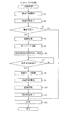
次に、図10及び図11を参照して、複合機10のCPU88で実行される印刷処理について説明する。図10は、複合機10のCPU88で実行される印刷処理を示したフローチャートである。   Next, a printing process executed by the CPU 88 of the multifunction machine 10 will be described with reference to FIGS. 10 and 11. FIG. 10 is a flowchart showing a printing process executed by the CPU 88 of the multifunction machine 10.

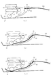
図11は、両面印刷時における記録用紙103の状態を示す模式図であり、図11(a)は、表面に画像が記録された記録用紙103が第1ローラ45及び第2ローラ46で挟持されて停止している状態、図11(b)は、第1ローラ45及び第2ローラ46によって反転案内部16の経路内を搬送されている記録用紙103が給紙ローラ25に到達した状態、図11(c)は、給紙ローラ25と、第1ローラ45及び第2ローラ46とによって記録用紙103が搬送されている状態を示している。   FIG. 11 is a schematic diagram showing the state of the recording paper 103 during double-sided printing. FIG. 11A shows the recording paper 103 with an image recorded on the front surface sandwiched between the first roller 45 and the second roller 46. FIG. 11B shows a state in which the recording paper 103 conveyed through the path of the reverse guide unit 16 by the first roller 45 and the second roller 46 has reached the paper feed roller 25. 11C shows a state in which the recording paper 103 is conveyed by the paper feed roller 25, the first roller 45, and the second roller 46. FIG.

この印刷処理は、印刷実行の指示が入力されると、給紙ローラ25を駆動して、給紙トレイ20から記録用紙103を矢印14の方向に沿って搬送路23内に搬送する。搬送路23内において、記録用紙103は、給紙ローラ25が当接した面とは反対の面(表面)が記録ヘッド39のノズル形成と対向するように反転される。そして、記録用紙103が搬送ローラ60及びピンチローラ31に到達すると、搬送ローラ60及びピンチローラ31で記録用紙103を挟持して、搬送ローラ60及びピンチローラ31によって記録用紙103を記録ヘッド39とプラテン42との間に搬送し、記録ヘッド39と対向する表面への画像記録を開始する(S1)。   In this printing process, when a print execution instruction is input, the paper feed roller 25 is driven to transport the recording paper 103 from the paper feed tray 20 into the transport path 23 along the direction of the arrow 14. In the conveyance path 23, the recording paper 103 is reversed so that the surface (front surface) opposite to the surface with which the paper feeding roller 25 contacts is opposed to the nozzle formation of the recording head 39. When the recording paper 103 reaches the conveying roller 60 and the pinch roller 31, the recording paper 103 is sandwiched by the conveying roller 60 and the pinch roller 31, and the recording paper 103 is moved between the recording head 39 and the platen by the conveying roller 60 and the pinch roller 31. The image recording onto the surface facing the recording head 39 is started (S1).

この場合、搬送ローラ60及びピンチローラ31によって記録用紙103を間欠的に搬送し、記録用紙103が停止している状態でキャリッジ38をスライドさせて記録ヘッド39によって記録用紙103の表面に画像を記録する。   In this case, the recording sheet 103 is intermittently conveyed by the conveying roller 60 and the pinch roller 31, and the carriage 38 is slid in a state where the recording sheet 103 is stopped, and an image is recorded on the surface of the recording sheet 103 by the recording head 39. To do.

また、記録用紙103が排紙ローラ62及び拍車ローラ63に到達すると、排紙ローラ62及び拍車ローラ63を駆動し、排紙ローラ62及び拍車ローラ63によって記録用紙103を更に下流側に搬送する。更に、記録用紙103が第1ローラ45及び第2ローラ46に到達すると、第1ローラ45及び第2ローラ46を駆動し、第1ローラ45及び第2ローラ46によって記録用紙103を更に下流側に搬送する。この間に、記録用紙103の表面への画像記録が終了する(S2)。   When the recording paper 103 reaches the paper discharge roller 62 and the spur roller 63, the paper discharge roller 62 and the spur roller 63 are driven, and the recording paper 103 is conveyed further downstream by the paper discharge roller 62 and the spur roller 63. Further, when the recording paper 103 reaches the first roller 45 and the second roller 46, the first roller 45 and the second roller 46 are driven, and the recording paper 103 is further moved downstream by the first roller 45 and the second roller 46. Transport. During this time, image recording on the surface of the recording paper 103 is completed (S2).

次に、画像記録モードが片面記録モードに設定されているか、両面記録モードに設定されているかを判断する(S3)。画像記録モードは、ユーザーが予め操作パネル40等を操作することにより設定する。操作パネル40から片面記録モード又は両面記録モードを指定するデータが制御部84のRAM90に送信され、これらのデータがRAM90に格納される。   Next, it is determined whether the image recording mode is set to the single-sided recording mode or the double-sided recording mode (S3). The image recording mode is set by the user operating the operation panel 40 or the like in advance. Data specifying the single-sided recording mode or the double-sided recording mode is transmitted from the operation panel 40 to the RAM 90 of the control unit 84, and these data are stored in the RAM 90.

もっとも、片面記録モードを指定するデータが予めROM89にデフォルト値として記憶されていてもよい。そして、制御部84がRAM90又はROM89から両面記録モードを指定するデータを読み込むことによって、記録用紙103の裏面にも画像が記録される。   However, data specifying the single-sided recording mode may be stored in advance in the ROM 89 as a default value. Then, when the control unit 84 reads data specifying the double-sided recording mode from the RAM 90 or the ROM 89, an image is also recorded on the back surface of the recording paper 103.

ユーザーが操作パネル40を操作することによって片面記録モードが設定されている場合は(S3:No)、表面に画像を記録した後(S2)、第1ローラ45及び第2ローラ46を引続き駆動して、記録用紙103を搬送方向下流側へ搬送し、排紙トレイ21へ排出する(S12)。尚、片面記録モードが設定されている場合は、経路切換部41は、常時、被記録媒体排出姿勢(図4参照)となっている。   When the single-side recording mode is set by the user operating the operation panel 40 (S3: No), after the image is recorded on the front surface (S2), the first roller 45 and the second roller 46 are continuously driven. Then, the recording paper 103 is conveyed downstream in the conveying direction and discharged to the paper discharge tray 21 (S12). When the single-sided recording mode is set, the path switching unit 41 is always in the recording medium ejection posture (see FIG. 4).

一方、ユーザーが操作パネル40を操作することによって両面記録モードが設定されている場合は(S3:Yes)、表面に画像を記録した後(S2)、図11(a)に示すように、第1ローラ45及び第2ローラ46を一旦停止し、経路切換部41を被記録媒体反転姿勢(図5参照)に駆動する(S4)。   On the other hand, when the double-sided recording mode is set by operating the operation panel 40 (S3: Yes), after the image is recorded on the front surface (S2), as shown in FIG. The first roller 45 and the second roller 46 are temporarily stopped, and the path switching unit 41 is driven to the recording medium reverse posture (see FIG. 5) (S4).

経路切換部41を記録用紙反転姿勢へ変化させるときは、第1ローラ45の中心軸52を中心として経路切換部41を回動する。すなわち、第2ローラ46は、記録用紙103を挟持したままで第1ローラ45の周面上を転動し、補助ローラ47によって記録用紙103を押圧する。   When the path switching unit 41 is changed to the recording sheet reversing posture, the path switching unit 41 is rotated about the central axis 52 of the first roller 45. That is, the second roller 46 rolls on the circumferential surface of the first roller 45 while holding the recording paper 103, and presses the recording paper 103 by the auxiliary roller 47.

言い換えると、第2ローラ46は、記録用紙103を第1ローラ45の周面に巻き付かせるように第1ローラ45の周面を転動する。これにより、記録用紙103が補助ローラ47によって表面側から反転案内部16に向けて押圧され、記録用紙103の上流側に位置する先端部(表面の後端、裏面の先端)が反転案内部16側に進入する(図5参照)。   In other words, the second roller 46 rolls on the peripheral surface of the first roller 45 so that the recording paper 103 is wound around the peripheral surface of the first roller 45. As a result, the recording paper 103 is pressed from the front surface side toward the reversing guide portion 16 by the auxiliary roller 47, and the leading end portion (the rear end of the front surface, the front end of the back surface) located on the upstream side of the recording paper 103 is reversed reversing guide portion 16. (See FIG. 5).

そして、第1ローラ45及び第2ローラ46を逆転し(S5)、記録用紙103を反転案内部16内において給紙ローラ25側に向けて搬送する(S6)。その後、記録用紙103の先端部(表面の後端、裏面の先端)が、図11(b)に示すように、給紙ローラ25に到達することになる。   Then, the first roller 45 and the second roller 46 are reversely rotated (S5), and the recording paper 103 is conveyed toward the paper feed roller 25 in the reverse guide 16 (S6). Thereafter, the leading end portion (the rear end on the front surface and the front end on the back surface) of the recording paper 103 reaches the paper feed roller 25 as shown in FIG.

この際には、直ちに、給紙ローラ25は駆動せず、所定時間が経過したかを判断し(S7)、所定時間が経過するまでは(S7:No)、S7の処理を繰り返し、所定時間が経過するまでの間は、引続き、第1ローラ45及び第2ローラ46を逆転させ続ける。これにより、記録用紙103の斜行が整えられ、給紙ローラ25による再給紙性を向上させることができる。   At this time, the paper feed roller 25 is not driven immediately, and it is determined whether or not a predetermined time has elapsed (S7), and until the predetermined time has elapsed (S7: No), the processing of S7 is repeated for a predetermined time. Until the time elapses, the first roller 45 and the second roller 46 are continuously reversed. Thereby, the skew of the recording paper 103 is adjusted, and the refeeding property by the paper feed roller 25 can be improved.

そして、所定時間が経過した後に(S7:Yes)、給紙ローラ25を駆動する(S8)。給紙ローラ25を駆動する場合には、給紙ローラ25による記録用紙103の搬送量が、第1ローラ45及び第2ローラ46による記録用紙103の搬送量よりも少なくなるよう、給紙ローラ25と、第1ローラ45及び第2ローラ46とを同時に駆動する。これにより、記録用紙103を、反転案内部16の経路内において、図11(c)に示すように、撓んだ状態で搬送させることができる。   Then, after a predetermined time has elapsed (S7: Yes), the paper feed roller 25 is driven (S8). When the paper feed roller 25 is driven, the paper feed roller 25 is set so that the transport amount of the recording paper 103 by the paper feed roller 25 is smaller than the transport amount of the recording paper 103 by the first roller 45 and the second roller 46. And the first roller 45 and the second roller 46 are simultaneously driven. Thereby, the recording paper 103 can be conveyed in a bent state as shown in FIG.

よって、記録用紙103を撓ませることなく搬送する場合に比べ、給紙ローラ25の搬送負荷が軽減され、給紙ローラ25がスリップし難くなり、給紙ローラ25がスリップすることで給紙ローラ25に当接する記録用紙103の表面に記録された画像が給紙ローラ25に転写され、記録用紙103の表面に記録された画像が損傷するのを抑制することができる。   Therefore, compared with the case where the recording sheet 103 is conveyed without being bent, the conveyance load of the sheet feeding roller 25 is reduced, the sheet feeding roller 25 is less likely to slip, and the sheet feeding roller 25 slips, thereby causing the sheet feeding roller 25 to slip. It is possible to suppress the image recorded on the surface of the recording paper 103 in contact with the recording paper 103 from being transferred to the paper feed roller 25 and damaging the image recorded on the surface of the recording paper 103.

その後は、上述したのと同様に、搬送路23において、記録用紙103は給紙ローラ25が当接した面(表面)とは反対の面(裏面)が記録ヘッド39のノズル形成と対向するように反転され、裏面に対して記録ヘッド39によって画像記録を開始する(S9)。   Thereafter, in the same way as described above, in the transport path 23, the surface (back surface) opposite to the surface (front surface) with which the sheet feeding roller 25 contacts the recording paper 103 faces the nozzle formation of the recording head 39. The image recording is started by the recording head 39 on the back surface (S9).

そして、記憶用紙103の先端部(裏面の先端)が経路切換部41に進入する前に、経路切換部41を被記録媒体反転姿勢(図5参照)から、再び被記録媒体排出姿勢(図4参照)に変化するように経路切換部41を駆動する(S10)。その後、記録用紙103の裏面への画像記録が終了し(S11)、両面に画像が記録された記録用紙103を第1ローラ45及び第2ローラ46によって搬送方向下流側へ搬送する。このとき、第1ローラ45及び第2ローラ46は正転し、記録用紙103は排紙トレイ21へ排出される(S12)。   Then, before the leading end (the leading end of the back surface) of the storage sheet 103 enters the path switching unit 41, the path switching unit 41 is moved again from the recording medium reversing posture (see FIG. 5) to the recording medium discharging posture (FIG. 4). The path switching unit 41 is driven so as to change to (see) (S10). Thereafter, image recording on the back surface of the recording paper 103 is completed (S11), and the recording paper 103 on which images are recorded on both sides is conveyed downstream in the conveying direction by the first roller 45 and the second roller 46. At this time, the first roller 45 and the second roller 46 rotate forward, and the recording paper 103 is discharged to the paper discharge tray 21 (S12).

以上、実施形態に基づき本発明を説明したが、本発明は上述した実施形態に何ら限定されるものではなく、本発明の趣旨を逸脱しない範囲内で種々の改良変更が可能であることは容易に推察できるものである。   Although the present invention has been described based on the embodiments, the present invention is not limited to the above-described embodiments, and various improvements and modifications can be easily made without departing from the spirit of the present invention. Can be inferred.

上述した実施形態では、図10のS8の処理において、給紙ローラ25を駆動する場合には、給紙ローラ25による記録用紙103の搬送量が、第1ローラ45及び第2ローラ46による記録用紙103の搬送量よりも少なくなるよう、給紙ローラ25と、第1ローラ45及び第2ローラ46とを同時に駆動する場合について説明した。   In the above-described embodiment, when the paper feed roller 25 is driven in the process of S8 in FIG. 10, the conveyance amount of the recording paper 103 by the paper feed roller 25 is the recording paper by the first roller 45 and the second roller 46. The case where the paper feed roller 25, the first roller 45, and the second roller 46 are simultaneously driven so as to be smaller than the conveyance amount 103 has been described.

しかし、これに代えて、給紙ローラ25を駆動する場合には、第1ローラ45及び第2ローラ46により記録用紙103が搬送された後に、その第1ローラ45及び第2ローラ46により搬送された搬送量よりも少ない搬送量で記録用紙103が給紙ローラ25により搬送されるように、第1ローラ45及び第2ローラ46と、給紙ローラ25とを交互に駆動するように構成しても良い。   However, instead of this, when the paper feed roller 25 is driven, the recording paper 103 is transported by the first roller 45 and the second roller 46 and then transported by the first roller 45 and the second roller 46. The first roller 45 and the second roller 46 and the paper feed roller 25 are driven alternately so that the recording paper 103 is transported by the paper feed roller 25 with a transport amount smaller than the transport amount. Also good.

かかる場合には、上述した実施形態と同様に、記録用紙103を、反転案内部16の経路内において、図11(c)に示すように、撓んだ状態で搬送させることができる。よって、記録用紙103を撓ませることなく搬送する場合に比べ、給紙ローラ25の搬送負荷が軽減され、給紙ローラ25がスリップし難くなり、給紙ローラ25がスリップすることで給紙ローラ25に当接する記録用紙103の表面に記録された画像が給紙ローラ25に転写され、記録用紙103の表面に記録された画像が損傷するのを抑制することができる。   In such a case, as in the above-described embodiment, the recording paper 103 can be conveyed in a bent state as shown in FIG. Therefore, compared with the case where the recording sheet 103 is conveyed without being bent, the conveyance load of the sheet feeding roller 25 is reduced, the sheet feeding roller 25 is less likely to slip, and the sheet feeding roller 25 slips, thereby causing the sheet feeding roller 25 to slip. It is possible to suppress the image recorded on the surface of the recording paper 103 in contact with the recording paper 103 from being transferred to the paper feed roller 25 and damaging the image recorded on the surface of the recording paper 103.

また、図10のS7の処理において、記録用紙103が、反転案内部16の経路内において撓んだ状態になる所定時間まで給紙ローラ25の駆動せず、記録用紙103が、反転案内部16の経路内において撓んだ状態になった後で、給紙ローラ25による記録用紙103の搬送量が、第1ローラ45及び第2ローラ46による記録用紙103の搬送量と同じになるように、給紙ローラ25と、第1ローラ45及び第2ローラ46とを同時または交互に駆動するように構成しても良い。かかる場合にも上述したのと同様な効果を奏することができる。   10, the recording paper 103 is not driven until a predetermined time until the recording paper 103 is bent in the path of the reversing guide unit 16, and the recording paper 103 is reversed by the reversing guide unit 16. After the sheet is bent in the path, the conveyance amount of the recording sheet 103 by the paper feed roller 25 is the same as the conveyance amount of the recording sheet 103 by the first roller 45 and the second roller 46. The paper feed roller 25 and the first roller 45 and the second roller 46 may be driven simultaneously or alternately. In such a case, the same effect as described above can be obtained.

本発明の一実施形態の複合機の外観斜視図である。1 is an external perspective view of a multifunction machine according to an embodiment of the present invention. 複合機のプリンタ部の構造を示す縦断面図である。FIG. 3 is a longitudinal sectional view illustrating a structure of a printer unit of the multifunction machine. プリンタ部の部分拡大断面図である。It is a partial expanded sectional view of a printer part. 経路切換部周辺を拡大して示す拡大断面図である。It is an expanded sectional view which expands and shows a route change part periphery. 経路切換部周辺を拡大して示す拡大断面図である。It is an expanded sectional view which expands and shows a route change part periphery. 経路切換部の斜視図である。It is a perspective view of a path switching part. 図6に示す矢印VII方向矢視図である。It is an arrow VII direction arrow line view shown in FIG. 図6に示す矢印VIII方向矢視図である。It is an arrow VIII direction arrow line view shown in FIG. 複合機の制御部の構成を示すブロック図である。FIG. 3 is a block diagram illustrating a configuration of a control unit of the multifunction machine. 印刷処理を示すフローチャートである。It is a flowchart which shows a printing process. 両面印刷時における記録用紙の状態を示す模式図である。It is a schematic diagram which shows the state of the recording paper at the time of duplex printing.

符号の説明Explanation of symbols

10 複合機(画像記録装置)
16 反転案内部(裏面用経路)
20 給紙トレイ(トレイ)
25 給紙ローラ
26 給紙アーム
39 記録ヘッド
45 第1ローラ(一対の送りローラ、他方のローラ)
46 第2ローラ(一対の送りローラ、従動ローラ)
47 補助ローラ
49 サブフレーム(経路切換アーム)
103 記録用紙(記録媒体)
S8 駆動制御手段
10 Multifunction machine (image recording device)
16 Reverse guide (rear path)
20 Paper tray (tray)
25 Paper feed roller 26 Paper feed arm 39 Recording head 45 First roller (a pair of feed rollers, the other roller)
46 Second roller (a pair of feed rollers, driven rollers)
47 Auxiliary roller 49 Subframe (path switching arm)
103 Recording paper (recording medium)
S8 Drive control means

Claims (5)

記録媒体にインクを吐出して画像を記録する記録ヘッドと、トレイに積載されている記録媒体に当接して、駆動源によって回転駆動されその記録媒体を給紙する給紙ローラとを備え、前記記録媒体の表面と裏面との両面に画像を記録可能な画像記録装置において、
前記記録ヘッドよりも下流側に配置され、正転および逆転可能に構成され、前記記録ヘッドを通過した記録媒体を挟持して、その挟持した記録媒体を外部に向けて、又は、前記記録媒体の前記記録ヘッドにより記録された表面が前記給紙ローラに当接するように再び前記給紙ローラに向けて搬送する一対の送りローラと、
その一対の送りローラと、前記記録ヘッドとを結ぶ経路から枝分かれして、前記給紙ローラに向かって延びる裏面用経路と、
その裏面用経路において前記記録媒体が撓んだ状態で搬送されるように、前記一対の送りローラと前記給紙ローラとを駆動させる駆動制御手段とを備え
前記一対の送りローラのうち、先に前記記録媒体の表面に当接する一方の送りローラは、他方の送りローラに従動して回転する従動ローラであり、
その従動ローラを一端側に回転自在に軸支して上流側に延び、前記他方の送りローラの回転軸を中心に回動可能に構成され、他端側が前記記録媒体に当接して、前記一対の送りローラに挟持されている記録媒体を、上流側に位置している先端部から前記裏面用経路に誘導する経路切換アームを備えていることを特徴とする画像記録装置。
A recording head that discharges ink onto a recording medium to record an image; and a paper feed roller that contacts the recording medium loaded on the tray and is rotated by a driving source to feed the recording medium, In an image recording apparatus capable of recording images on both the front and back surfaces of a recording medium,
The recording medium is disposed downstream of the recording head and is configured to be capable of normal rotation and reverse rotation. The recording medium that has passed through the recording head is sandwiched, and the sandwiched recording medium is directed to the outside. A pair of feed rollers that convey again toward the paper feed roller so that the surface recorded by the recording head contacts the paper feed roller;
A back surface path branched from a path connecting the pair of feed rollers and the recording head and extending toward the paper feed roller;
Drive control means for driving the pair of feed rollers and the paper feed roller so that the recording medium is conveyed in a bent state in the back surface path ;
Of the pair of feed rollers, one feed roller that first contacts the surface of the recording medium is a driven roller that rotates following the other feed roller,
The driven roller is rotatably supported at one end side and extends upstream, and is configured to be rotatable about the rotation shaft of the other feed roller. The other end abuts the recording medium, and the pair An image recording apparatus comprising: a path switching arm for guiding a recording medium sandwiched between the feeding rollers from a leading end located upstream to the path for the back surface .
前記駆動制御手段は、前記一対の送りローラから前記裏面用経路を通って搬送される記録媒体が前記給紙ローラに当接した後も前記一対の送りローラを駆動させ、所定時間経過後に、前記給紙ローラを駆動させることを特徴とする請求項1に記載の画像記録装置。   The drive control means drives the pair of feed rollers even after the recording medium conveyed from the pair of feed rollers through the back surface path contacts the paper feed roller, and after a predetermined time has elapsed, The image recording apparatus according to claim 1, wherein a paper feed roller is driven. 前記駆動制御手段は、前記一対の送りローラによる前記記録媒体の搬送量が前記給紙ローラによる前記記録媒体の搬送量よりも大きくなるように、前記一対の送りローラと前記給紙ローラとを同時に駆動させることを特徴とする請求項1又は2に記載の画像記録装置。   The drive control unit simultaneously moves the pair of feed rollers and the paper feed roller so that the transport amount of the recording medium by the pair of feed rollers is larger than the transport amount of the recording medium by the paper feed roller. The image recording apparatus according to claim 1, wherein the image recording apparatus is driven. 前記駆動制御手段は、前記一対の送りローラによって前記記録媒体が搬送された後に、その一対の送りローラによって搬送された搬送量よりも少ない搬送量で前記記録媒体が前記給紙ローラによって搬送されるように、前記一対の送りローラと前記給紙ローラとを交互に駆動させることを特徴とする請求項1又は2に記載の画像記録装置。   In the drive control unit, after the recording medium is transported by the pair of feed rollers, the recording medium is transported by the paper feed roller with a transport amount smaller than the transport amount transported by the pair of feed rollers. The image recording apparatus according to claim 1, wherein the pair of feed rollers and the paper feed roller are alternately driven. 前記経路切換アームの他端側には、前記記録媒体に当接する補助ローラが回転自在に軸支されていることを特徴とする請求項1から4のいずれかに記載の画像記録装置。
The path on the other end of the switching arm, an image recording apparatus according to any one of claims 1 to 4, characterized in that the auxiliary roller abutting on the recording medium is rotatably supported.
JP2007254648A 2007-09-28 2007-09-28 Image recording device Expired - Fee Related JP5056314B2 (en)

Priority Applications (3)

Application Number Priority Date Filing Date Title
JP2007254648A JP5056314B2 (en) 2007-09-28 2007-09-28 Image recording device
US12/239,517 US8092004B2 (en) 2007-09-28 2008-09-26 Image recording apparatus
CN2008101681442A CN101396927B (en) 2007-09-28 2008-09-28 Image recording apparatus

Applications Claiming Priority (1)

Application Number Priority Date Filing Date Title
JP2007254648A JP5056314B2 (en) 2007-09-28 2007-09-28 Image recording device

Publications (2)

Publication Number Publication Date
JP2009083232A JP2009083232A (en) 2009-04-23
JP5056314B2 true JP5056314B2 (en) 2012-10-24

Family

ID=40508555

Family Applications (1)

Application Number Title Priority Date Filing Date
JP2007254648A Expired - Fee Related JP5056314B2 (en) 2007-09-28 2007-09-28 Image recording device

Country Status (3)

Country Link
US (1) US8092004B2 (en)
JP (1) JP5056314B2 (en)
CN (1) CN101396927B (en)

Families Citing this family (11)

* Cited by examiner, † Cited by third party
Publication number Priority date Publication date Assignee Title
JP4905310B2 (en) * 2007-09-28 2012-03-28 ブラザー工業株式会社 Image recording device
JP5504889B2 (en) * 2009-12-29 2014-05-28 ブラザー工業株式会社 Image recording device
US8768235B2 (en) 2009-12-29 2014-07-01 Brother Kogyo Kabushiki Kaisha Double-sided image recording device having a compact form factor
JP5316404B2 (en) 2009-12-29 2013-10-16 ブラザー工業株式会社 Image recording device
JP2011157155A (en) 2010-01-29 2011-08-18 Brother Industries Ltd Image recording device
KR20120043428A (en) * 2010-10-26 2012-05-04 삼성전자주식회사 Image forming apparatus and method for controlling thereof
JP5942568B2 (en) * 2012-04-23 2016-06-29 ブラザー工業株式会社 Image recording device
US8760739B2 (en) 2012-07-05 2014-06-24 Xerox Corporation Dynamic scanner with width sensing and single point sensor
JP6237420B2 (en) * 2014-03-31 2017-11-29 ブラザー工業株式会社 Image recording device
US10725422B2 (en) * 2018-10-25 2020-07-28 Lexmark International, Inc. Toner cartridge electrical contacts
JP2021186973A (en) * 2020-05-25 2021-12-13 セイコーエプソン株式会社 Recording device

Family Cites Families (16)

* Cited by examiner, † Cited by third party
Publication number Priority date Publication date Assignee Title
JPH09290931A (en) * 1996-02-28 1997-11-11 Brother Ind Ltd Paper sheet carrying device and printer
EP0841601A1 (en) * 1996-10-08 1998-05-13 Océ-Technologies B.V. Method of scheduling a sequence of pages to be printed with a duplex printer
JP3681093B2 (en) * 1998-06-12 2005-08-10 株式会社リコー Inkjet recording device
US5974298A (en) * 1998-08-28 1999-10-26 Tektronix, Inc. Duplex printing media handling system
DE60036444T2 (en) * 1999-10-05 2008-06-12 Seiko Epson Corp. Two-sided printing in an inkjet printer
JP3875003B2 (en) 2000-08-10 2007-01-31 株式会社リコー Paper transport device
JP2003043844A (en) * 2001-07-30 2003-02-14 Fujitsu Ltd Image forming device and paper carrying control method
JP3931966B2 (en) * 2002-01-31 2007-06-20 セイコーエプソン株式会社 Recording device
US6679600B1 (en) * 2002-07-24 2004-01-20 Hewlett-Packard Development Company, L.P. Methods and apparatus for increasing image gloss
KR100637911B1 (en) * 2002-11-26 2006-10-24 가부시키가이샤 리코 Stably operable image-forming apparatus with improved paper conveying and ejecting mechanism
JP4158563B2 (en) * 2003-03-12 2008-10-01 ブラザー工業株式会社 Double-sided recording device
JP4012500B2 (en) 2003-12-04 2007-11-21 京セラミタ株式会社 Image forming apparatus
KR100694067B1 (en) * 2004-11-23 2007-03-12 삼성전자주식회사 Image forming apparatus
JP4221604B2 (en) * 2005-05-27 2009-02-12 ブラザー工業株式会社 Image recording device
JP4687287B2 (en) * 2005-07-05 2011-05-25 富士ゼロックス株式会社 Droplet discharge device
JP4735112B2 (en) * 2005-08-04 2011-07-27 ブラザー工業株式会社 Inkjet recording device

Also Published As

Publication number Publication date
US20090087239A1 (en) 2009-04-02
US8092004B2 (en) 2012-01-10
CN101396927A (en) 2009-04-01
CN101396927B (en) 2011-02-02
JP2009083232A (en) 2009-04-23

Similar Documents

Publication Publication Date Title
JP5056314B2 (en) Image recording device
JP5130853B2 (en) Image recording device
JP4905310B2 (en) Image recording device
JP5360342B2 (en) Double-sided recording device
JP4306743B2 (en) Image recording device
JP5845648B2 (en) Recording device
US8038248B2 (en) Image recording apparatus
JP4670954B2 (en) Image recording device
JP2010082831A (en) Image recording apparatus
JP4265593B2 (en) Inkjet recording device
JP2008246803A (en) Image recorder
US8020986B2 (en) Image recording apparatus
JP2009083380A (en) Image recording apparatus
JP4613968B2 (en) Paper storage device and image recording device
JP4715773B2 (en) Image recording device
JP5605007B2 (en) Image recording device
JP5494745B2 (en) Image recording device
JP2008246672A (en) Image recorder
JP4492673B2 (en) Image recording device
JP2009154404A (en) Image recorder
JP4600492B2 (en) Image recording device
JP2009208272A (en) Image recording device
JP2008246801A (en) Image recorder
JP4877301B2 (en) Image recording apparatus and recording paper conveyance control method
JP2009090498A (en) Image recording device

Legal Events

Date Code Title Description
A621 Written request for application examination

Free format text: JAPANESE INTERMEDIATE CODE: A621

Effective date: 20100129

A977 Report on retrieval

Free format text: JAPANESE INTERMEDIATE CODE: A971007

Effective date: 20110804

A131 Notification of reasons for refusal

Free format text: JAPANESE INTERMEDIATE CODE: A131

Effective date: 20110816

A521 Written amendment

Free format text: JAPANESE INTERMEDIATE CODE: A523

Effective date: 20111014

A131 Notification of reasons for refusal

Free format text: JAPANESE INTERMEDIATE CODE: A131

Effective date: 20120417

A521 Written amendment

Free format text: JAPANESE INTERMEDIATE CODE: A523

Effective date: 20120611

TRDD Decision of grant or rejection written
A01 Written decision to grant a patent or to grant a registration (utility model)

Free format text: JAPANESE INTERMEDIATE CODE: A01

Effective date: 20120703

A01 Written decision to grant a patent or to grant a registration (utility model)

Free format text: JAPANESE INTERMEDIATE CODE: A01

A61 First payment of annual fees (during grant procedure)

Free format text: JAPANESE INTERMEDIATE CODE: A61

Effective date: 20120716

FPAY Renewal fee payment (event date is renewal date of database)

Free format text: PAYMENT UNTIL: 20150810

Year of fee payment: 3

R150 Certificate of patent or registration of utility model

Ref document number: 5056314

Country of ref document: JP

Free format text: JAPANESE INTERMEDIATE CODE: R150

Free format text: JAPANESE INTERMEDIATE CODE: R150

LAPS Cancellation because of no payment of annual fees