JP5052494B2 - Aerosol dispenser - Google Patents
Aerosol dispenser Download PDFInfo
- Publication number
- JP5052494B2 JP5052494B2 JP2008500255A JP2008500255A JP5052494B2 JP 5052494 B2 JP5052494 B2 JP 5052494B2 JP 2008500255 A JP2008500255 A JP 2008500255A JP 2008500255 A JP2008500255 A JP 2008500255A JP 5052494 B2 JP5052494 B2 JP 5052494B2
- Authority
- JP
- Japan
- Prior art keywords
- flow
- opening
- gas
- aerosol dispenser
- flow rate
- Prior art date
- Legal status (The legal status is an assumption and is not a legal conclusion. Google has not performed a legal analysis and makes no representation as to the accuracy of the status listed.)
- Expired - Fee Related
Links
Images


Classifications
-
- B—PERFORMING OPERATIONS; TRANSPORTING
- B65—CONVEYING; PACKING; STORING; HANDLING THIN OR FILAMENTARY MATERIAL
- B65D—CONTAINERS FOR STORAGE OR TRANSPORT OF ARTICLES OR MATERIALS, e.g. BAGS, BARRELS, BOTTLES, BOXES, CANS, CARTONS, CRATES, DRUMS, JARS, TANKS, HOPPERS, FORWARDING CONTAINERS; ACCESSORIES, CLOSURES, OR FITTINGS THEREFOR; PACKAGING ELEMENTS; PACKAGES
- B65D83/00—Containers or packages with special means for dispensing contents
- B65D83/14—Containers or packages with special means for dispensing contents for delivery of liquid or semi-liquid contents by internal gaseous pressure, i.e. aerosol containers comprising propellant for a product delivered by a propellant
- B65D83/44—Valves specially adapted therefor; Regulating devices
-
- B—PERFORMING OPERATIONS; TRANSPORTING
- B05—SPRAYING OR ATOMISING IN GENERAL; APPLYING FLUENT MATERIALS TO SURFACES, IN GENERAL
- B05B—SPRAYING APPARATUS; ATOMISING APPARATUS; NOZZLES
- B05B1/00—Nozzles, spray heads or other outlets, with or without auxiliary devices such as valves, heating means
- B05B1/34—Nozzles, spray heads or other outlets, with or without auxiliary devices such as valves, heating means designed to influence the nature of flow of the liquid or other fluent material, e.g. to produce swirl
- B05B1/3405—Nozzles, spray heads or other outlets, with or without auxiliary devices such as valves, heating means designed to influence the nature of flow of the liquid or other fluent material, e.g. to produce swirl to produce swirl
- B05B1/341—Nozzles, spray heads or other outlets, with or without auxiliary devices such as valves, heating means designed to influence the nature of flow of the liquid or other fluent material, e.g. to produce swirl to produce swirl before discharging the liquid or other fluent material, e.g. in a swirl chamber upstream the spray outlet
- B05B1/3415—Nozzles, spray heads or other outlets, with or without auxiliary devices such as valves, heating means designed to influence the nature of flow of the liquid or other fluent material, e.g. to produce swirl to produce swirl before discharging the liquid or other fluent material, e.g. in a swirl chamber upstream the spray outlet with swirl imparting inserts upstream of the swirl chamber
-
- B—PERFORMING OPERATIONS; TRANSPORTING
- B05—SPRAYING OR ATOMISING IN GENERAL; APPLYING FLUENT MATERIALS TO SURFACES, IN GENERAL
- B05B—SPRAYING APPARATUS; ATOMISING APPARATUS; NOZZLES
- B05B1/00—Nozzles, spray heads or other outlets, with or without auxiliary devices such as valves, heating means
- B05B1/34—Nozzles, spray heads or other outlets, with or without auxiliary devices such as valves, heating means designed to influence the nature of flow of the liquid or other fluent material, e.g. to produce swirl
- B05B1/3405—Nozzles, spray heads or other outlets, with or without auxiliary devices such as valves, heating means designed to influence the nature of flow of the liquid or other fluent material, e.g. to produce swirl to produce swirl
- B05B1/341—Nozzles, spray heads or other outlets, with or without auxiliary devices such as valves, heating means designed to influence the nature of flow of the liquid or other fluent material, e.g. to produce swirl to produce swirl before discharging the liquid or other fluent material, e.g. in a swirl chamber upstream the spray outlet
- B05B1/3421—Nozzles, spray heads or other outlets, with or without auxiliary devices such as valves, heating means designed to influence the nature of flow of the liquid or other fluent material, e.g. to produce swirl to produce swirl before discharging the liquid or other fluent material, e.g. in a swirl chamber upstream the spray outlet with channels emerging substantially tangentially in the swirl chamber
- B05B1/3426—Nozzles, spray heads or other outlets, with or without auxiliary devices such as valves, heating means designed to influence the nature of flow of the liquid or other fluent material, e.g. to produce swirl to produce swirl before discharging the liquid or other fluent material, e.g. in a swirl chamber upstream the spray outlet with channels emerging substantially tangentially in the swirl chamber the channels emerging in the swirl chamber perpendicularly to the outlet axis
-
- B—PERFORMING OPERATIONS; TRANSPORTING
- B05—SPRAYING OR ATOMISING IN GENERAL; APPLYING FLUENT MATERIALS TO SURFACES, IN GENERAL
- B05B—SPRAYING APPARATUS; ATOMISING APPARATUS; NOZZLES
- B05B1/00—Nozzles, spray heads or other outlets, with or without auxiliary devices such as valves, heating means
- B05B1/34—Nozzles, spray heads or other outlets, with or without auxiliary devices such as valves, heating means designed to influence the nature of flow of the liquid or other fluent material, e.g. to produce swirl
- B05B1/3405—Nozzles, spray heads or other outlets, with or without auxiliary devices such as valves, heating means designed to influence the nature of flow of the liquid or other fluent material, e.g. to produce swirl to produce swirl
- B05B1/341—Nozzles, spray heads or other outlets, with or without auxiliary devices such as valves, heating means designed to influence the nature of flow of the liquid or other fluent material, e.g. to produce swirl to produce swirl before discharging the liquid or other fluent material, e.g. in a swirl chamber upstream the spray outlet
- B05B1/3421—Nozzles, spray heads or other outlets, with or without auxiliary devices such as valves, heating means designed to influence the nature of flow of the liquid or other fluent material, e.g. to produce swirl to produce swirl before discharging the liquid or other fluent material, e.g. in a swirl chamber upstream the spray outlet with channels emerging substantially tangentially in the swirl chamber
- B05B1/3431—Nozzles, spray heads or other outlets, with or without auxiliary devices such as valves, heating means designed to influence the nature of flow of the liquid or other fluent material, e.g. to produce swirl to produce swirl before discharging the liquid or other fluent material, e.g. in a swirl chamber upstream the spray outlet with channels emerging substantially tangentially in the swirl chamber the channels being formed at the interface of cooperating elements, e.g. by means of grooves
- B05B1/3436—Nozzles, spray heads or other outlets, with or without auxiliary devices such as valves, heating means designed to influence the nature of flow of the liquid or other fluent material, e.g. to produce swirl to produce swirl before discharging the liquid or other fluent material, e.g. in a swirl chamber upstream the spray outlet with channels emerging substantially tangentially in the swirl chamber the channels being formed at the interface of cooperating elements, e.g. by means of grooves the interface being a plane perpendicular to the outlet axis
-
- B—PERFORMING OPERATIONS; TRANSPORTING
- B05—SPRAYING OR ATOMISING IN GENERAL; APPLYING FLUENT MATERIALS TO SURFACES, IN GENERAL
- B05B—SPRAYING APPARATUS; ATOMISING APPARATUS; NOZZLES
- B05B1/00—Nozzles, spray heads or other outlets, with or without auxiliary devices such as valves, heating means
- B05B1/34—Nozzles, spray heads or other outlets, with or without auxiliary devices such as valves, heating means designed to influence the nature of flow of the liquid or other fluent material, e.g. to produce swirl
- B05B1/3405—Nozzles, spray heads or other outlets, with or without auxiliary devices such as valves, heating means designed to influence the nature of flow of the liquid or other fluent material, e.g. to produce swirl to produce swirl
- B05B1/341—Nozzles, spray heads or other outlets, with or without auxiliary devices such as valves, heating means designed to influence the nature of flow of the liquid or other fluent material, e.g. to produce swirl to produce swirl before discharging the liquid or other fluent material, e.g. in a swirl chamber upstream the spray outlet
- B05B1/3421—Nozzles, spray heads or other outlets, with or without auxiliary devices such as valves, heating means designed to influence the nature of flow of the liquid or other fluent material, e.g. to produce swirl to produce swirl before discharging the liquid or other fluent material, e.g. in a swirl chamber upstream the spray outlet with channels emerging substantially tangentially in the swirl chamber
- B05B1/3431—Nozzles, spray heads or other outlets, with or without auxiliary devices such as valves, heating means designed to influence the nature of flow of the liquid or other fluent material, e.g. to produce swirl to produce swirl before discharging the liquid or other fluent material, e.g. in a swirl chamber upstream the spray outlet with channels emerging substantially tangentially in the swirl chamber the channels being formed at the interface of cooperating elements, e.g. by means of grooves
- B05B1/3442—Nozzles, spray heads or other outlets, with or without auxiliary devices such as valves, heating means designed to influence the nature of flow of the liquid or other fluent material, e.g. to produce swirl to produce swirl before discharging the liquid or other fluent material, e.g. in a swirl chamber upstream the spray outlet with channels emerging substantially tangentially in the swirl chamber the channels being formed at the interface of cooperating elements, e.g. by means of grooves the interface being a cone having the same axis as the outlet
Abstract
Description
この発明は、エアロゾル(aerosol)ディスペンサーに関する。 The present invention relates to an aerosol dispenser.
圧力下で製品が貯蔵される容器又はキャニスターを有するエアロゾルディスペンサーを提供することは公知である。開いた時に容器から製品が分注可能となるようなバルブが備えられる。分注される製品は大抵、例えば溶液(liquor)のような液体であり、さらに容器内には、少なくとも一部が圧縮ガスである高圧ガスも存在する。ブタンのようないくつかの高圧ガスは、一部がガスであり、一部が液体製品内で溶液となり得る液体として存在する。圧縮空気又は窒素のような他の高圧ガスはガスとしてのみ存在し、二酸化炭素のような高圧ガスでは、限られた量のガスが液体内で懸濁液の状態で存在し得る。ある種のエアロゾルディスペンサーでは、容器内の可撓性の袋(flexible bag)に液体が保持され、そこで高圧ガスから分離される。 It is known to provide aerosol dispensers having containers or canisters in which products are stored under pressure. A valve is provided that allows the product to be dispensed from the container when opened. The product to be dispensed is usually a liquid such as a liquor, and there is also a high-pressure gas in the container, at least partly a compressed gas. Some high pressure gases, such as butane, exist as liquids, some of which are gases and some are solutions in liquid products. Other high pressure gases such as compressed air or nitrogen exist only as gases, and in high pressure gases such as carbon dioxide, a limited amount of gas may be present in suspension in the liquid. In some aerosol dispensers, liquid is held in a flexible bag within the container where it is separated from the high pressure gas.
多くの場合、バルブステム(stem)によってノズルが出口弁に取付けられ、それによって用途に適した形態と方向に製品が確実に送られる。多くのエアロゾルは、出口弁に取付けられた噴霧ノズルを有し、上記ノズルは、圧力下でノズルを通過する液体流がノズルの出口オリフィスを通過する時に壊れて又は「噴霧化」(atomize)して多数の液滴になり、噴霧化したスプレー又は霧となるよう構成される。例えば、制汗スプレー、消臭スプレー、香水、芳香剤、消毒剤、塗料、殺虫剤、つや出し剤、ヘアケア製品、医薬品、水及び潤滑剤を含む形態で、多数の市販品が消費者に提供されている。 In many cases, a valve stem attaches the nozzle to the outlet valve, thereby ensuring that the product is delivered in the form and direction suitable for the application. Many aerosols have a spray nozzle attached to an outlet valve that breaks or `` atomizes '' when a liquid stream passing through the nozzle under pressure passes through the nozzle's outlet orifice. It becomes a large number of droplets and is configured to be an atomized spray or mist. Numerous commercial products are offered to consumers in forms including, for example, antiperspirant sprays, deodorant sprays, perfumes, fragrances, disinfectants, paints, insecticides, polishes, hair care products, pharmaceuticals, water and lubricants. ing.
スプレーに要求される液滴の最適な大きさは、主として関係する個々の製品、及びそれが意図する用途による。例えば、患者(例えば、喘息患者)によって吸入される薬物を含む医薬品スプレーは、肺に深く浸透できるように通常は極めて小さな液滴を必要とする。これに対し、つや出しスプレーは、つや出しされる表面にエアロゾル液滴が衝突するのを促進すると共に、特にスプレーが毒性の場合に吸入される程度を減らすよう、好ましくはより大きな直径のスプレー液滴を含む。 The optimum droplet size required for spraying depends primarily on the individual product involved and the application for which it is intended. For example, pharmaceutical sprays containing drugs that are inhaled by a patient (eg, an asthmatic patient) usually require very small droplets so that they can penetrate deep into the lungs. In contrast, glossy sprays preferably encourage larger diameter spray droplets to promote the impact of aerosol droplets on the surface being polished and to reduce the extent to which the spray is inhaled, especially when the spray is toxic. Including.
従来のノズル装置によって形成されるエアロゾル液滴の大きさは、出口オリフィスの大きさ、及び流体がノズルを通過させられるための圧力を含む多くの因子に影響される。しかし、微小で粒径分布が狭い液滴を含むスプレーを形成したい場合、特に低圧の場合に問題が生じる。スプレーを生成するために低圧を用いることは、スプレー中に存在する高圧ガスの量を低減し、又は圧縮空気のようなより低圧を発生する他の高圧ガスを使用できるため、ますます好都合である。低圧で高品質のスプレーを提供する問題は、流体を充分に小さな液滴に霧化するのが困難になるため、関与する(concerned)流体が高粘度を有する場合にさらに深刻になる。 The size of the aerosol droplets formed by conventional nozzle devices is affected by many factors, including the size of the exit orifice and the pressure with which the fluid is passed through the nozzle. However, a problem arises when it is desired to form a spray containing droplets having a small particle size distribution and particularly at a low pressure. Using low pressure to produce a spray is more and more advantageous because it reduces the amount of high pressure gas present in the spray, or other high pressure gases that generate a lower pressure such as compressed air can be used. . The problem of providing a high-quality spray at low pressure becomes even more acute when the concerned fluid has a high viscosity because it becomes difficult to atomize the fluid into sufficiently small droplets.
従来のバルブ及びノズル装置に取付けられる周知の加圧型のエアロゾル容器についての更なる問題は、エアロゾルディスペンサーの寿命の間、特に、内容物が除々に減少するに従い容器内の圧力が低減するようにディスペンサーの寿命が最後に向かうにつれて、生成されたエアロゾル液滴の大きさが増大する傾向にあることである。この圧力低下は、生成されるエアロゾル液滴の目に見える増加を引き起こし、更に、これにより生成されたスプレーの質が低下する。 A further problem with known pressurized aerosol containers attached to conventional valve and nozzle devices is that the dispenser is designed to reduce the pressure in the container over the life of the aerosol dispenser, particularly as the contents gradually decrease. The size of the aerosol droplets generated tends to increase as the lifetime of This pressure drop causes a visible increase in the generated aerosol droplets, which further reduces the quality of the generated spray.
ディスペンサーの寿命の間での圧力降下量は、使用される高圧ガスのタイプによって変化する。容器内に液体としてもガスとしても存在するブタンのような高圧ガスの場合、ディスペンサーの寿命の間での圧力降下量は、20-30%であろう。このタイプの高圧ガスでは、製品が消耗するにつれてより多くのガスが溶液から流出し、容器内の圧力が降下する。主に又は専ら圧縮ガスとして存在する高圧ガスと比べると、全体的な圧力降下は50%以上であろう。 The amount of pressure drop over the life of the dispenser varies depending on the type of high pressure gas used. In the case of a high pressure gas such as butane that exists both as a liquid and as a gas in the container, the pressure drop over the life of the dispenser will be 20-30%. With this type of high pressure gas, as the product is consumed, more gas flows out of the solution and the pressure in the container drops. Compared to high-pressure gas that exists mainly or exclusively as compressed gas, the overall pressure drop will be 50% or more.
液滴の破壊を助け、噴霧化を向上させるため、いくつかの公知のエアロゾルディスペンサーバルブは、バルブの筐体内に1又はそれ以上の細孔を備え、バルブを通って液体製品が分注される際、そのバルブを通って高圧ガスが液体製品内に流入することができる。これらの孔は気相栓(vapour phase tap;VPT)として知られている。 To help break the droplets and improve nebulization, some known aerosol dispenser valves have one or more pores in the valve housing through which the liquid product is dispensed. In doing so, high pressure gas can flow into the liquid product through the valve. These holes are known as vapor phase taps (VPTs).
VPTを使用する際の問題は、高圧ガスがより早く消費され、ディスペンサーの寿命の間での容器内圧力の損失に関し、上記した問題が深刻になることである。これは、使用される高圧ガスに無関係な問題であるが、高圧ガスが空気又は窒素のような圧縮ガスである場合に特有の問題であり、この場合、内容物が消費されるにつれて圧力損失が受け入れ難い性能をもたらすであろう。例えば、VPTを有さずに高圧ガスとして圧縮ガスを用いる典型的なディスペンサーにおいては、始動圧力は約10barであり約4barに低下する。しかし、VPTが使用される場合、圧力は液体を霧化するのに不十分な2bar以下に下がるかもしれない。 The problem with using VPT is that the high pressure gas is consumed more quickly and the above mentioned problems become more serious with respect to the loss of pressure in the container during the life of the dispenser. This is a problem unrelated to the high-pressure gas used, but is a particular problem when the high-pressure gas is a compressed gas such as air or nitrogen, in which case the pressure loss increases as the contents are consumed. It will bring unacceptable performance. For example, in a typical dispenser that uses compressed gas as the high pressure gas without VPT, the starting pressure is about 10 bar and drops to about 4 bar. However, when VPT is used, the pressure may drop below 2 bar, which is insufficient to atomize the liquid.
液体製品を噴霧化するため、容器内が一杯で圧力が高い時に比べて容器内の圧力が低い時に、VPTが液体に対する高圧ガスの比を高くするならば好ましい。これは、高圧ではVPTを通って液体流に高圧ガスが導入されなくても、必要な噴霧化を生じさせるためにノズルを通る比較的高速の液体流はそのままで充分であるからである。しかし、従来のVPTでは、容器内の圧力が降下するにつれ、液体に対する高圧ガスの比が下がるような逆効果が見られる。これはVPTを通る流れを考慮することによって説明できる。筐体を通って流れる液体が筐体の外側のガスより低圧のため、ガスはVPTを通って流れ、さらにVPTを通って流れるガスの流量(rate)は、VPTの断面積とそれを横断する圧力差の関数となる。VPTの断面積は固定されているため、容器内の圧力が低下するにつれてVPTを通る体積流量(volumetric flow rate)は低下する。 In order to atomize a liquid product, it is preferable if the VPT increases the ratio of high pressure gas to liquid when the pressure in the container is low compared to when the container is full and pressure is high. This is because at high pressures, a relatively high-speed liquid flow through the nozzle is sufficient to produce the necessary nebulization, even if high-pressure gas is not introduced into the liquid flow through the VPT. However, the conventional VPT has an adverse effect that the ratio of the high pressure gas to the liquid decreases as the pressure in the container decreases. This can be explained by considering the flow through the VPT. Since the liquid flowing through the enclosure is at a lower pressure than the gas outside the enclosure, the gas will flow through the VPT, and the rate of gas flowing through the VPT will cross the cross section of the VPT It is a function of the pressure difference. Since the cross-sectional area of the VPT is fixed, the volumetric flow rate through the VPT decreases as the pressure in the container decreases.
ディスペンサーの寿命の限界に向かって容器内圧力が低下した時に液体の適切な噴霧化を提供するよう、充分なガスが液体に流入するのを確実にするため、VPT開口は特定の最小サイズでなければならない。しかし、このことは、容器が一杯で圧力が高い時には、過剰な高圧ガスが液体に流入することを意味する。そのため従来のVPTでは、容器が比較的一杯の時、液体の適切な噴霧化を確実にするのに必須でないものとして、VPTを通って流れる高圧ガスのかなりの量が無駄になることが見受けられる。高圧ガスが圧縮し易く、そのため所定の体積流量に対し、容器がほとんど空で容器内圧力が低下した時に比べて容器が一杯で圧力が最大の時、多量のガスがVPTを通過するため、この問題はさらに悪化する。 The VPT opening must be of a certain minimum size to ensure that sufficient gas flows into the liquid to provide proper atomization of the liquid when the pressure in the container decreases towards the limit of the dispenser's life. I must. However, this means that when the container is full and the pressure is high, excess high pressure gas flows into the liquid. Thus, in conventional VPT, it can be seen that a considerable amount of high-pressure gas flowing through the VPT is wasted as not essential to ensure proper atomization of the liquid when the container is relatively full. . High pressure gas is easy to compress, so for a given volume flow rate, a large amount of gas passes through the VPT when the container is full and the pressure is maximum compared to when the container is almost empty and the pressure inside the container is reduced. The problem gets worse.
VPTを通ってガスがバルブ筐体に送られる方法を変えることは、液滴サイズとエアロゾルのスプレー形状に著しい差を与えることが明らかになっている。特に、数個の小孔は、1個の大きな孔より良い結果をもたらすことが見出されている。しかし、小孔を製造するのは困難が伴う。一般的に、バルブ筐体はポリマー材料から射出成形され、VPT孔は金型内のピンを用いて製造される。より小さい孔を製造するためには、ピンの寸法を縮小する必要があるが、極めて小さいピンが使用されるとそれらが破損する傾向にある。極めて小さいピンによる更なる問題は、それらが詰まり得ることである。 Changing the way gas is delivered to the valve housing through the VPT has been shown to make a significant difference in droplet size and aerosol spray shape. In particular, several small holes have been found to give better results than one large hole. However, it is difficult to manufacture small holes. Generally, the valve housing is injection molded from a polymer material, and the VPT holes are manufactured using pins in the mold. In order to produce smaller holes, it is necessary to reduce the size of the pins, but if very small pins are used, they tend to break. A further problem with very small pins is that they can become clogged.
従来技術のディスペンサーの問題を解消し、又は少なくとも軽減する改良されたエアロゾルディスペンサーを提供する必要がある。 There is a need to provide an improved aerosol dispenser that eliminates or at least reduces the problems of prior art dispensers.
特に、VPTを有し、VPTを通って液体製品に流入する高圧ガス全体量を低減し、さらにディスペンサーの寿命の間で液体の適切な噴霧化を確実にする改良されたエアロゾルディスペンサーを提供する必要がある。 In particular, there is a need to provide an improved aerosol dispenser that has a VPT, reduces the total amount of high-pressure gas that flows into the liquid product through the VPT, and also ensures proper atomization of the liquid over the life of the dispenser There is.
本発明によれば、分注される液体製品を収容するのに適した容器と、少なくとも一部がガスとして前記容器内に存在する高圧ガスとを含むエアロゾルディスペンサーであって、前記ディスペンサーは、前記容器からの前記液体製品の放出を調整するためのバルブと、分注される際に前記液体製品内に前記ガス状高圧ガスの一部を導入する手段とを有し、前記ディスペンサーはさらに、前記容器内の内容物の圧力に依存して、前記高圧ガスが前記液体製品内に導入される割合を変えるための流量調整手段を有することを特徴とするエアロゾルディスペンサーが提供される。 According to the present invention, there is provided an aerosol dispenser comprising a container suitable for containing a liquid product to be dispensed, and a high-pressure gas at least part of which is present in the container as a gas, the dispenser comprising: A valve for regulating the release of the liquid product from the container and means for introducing a portion of the gaseous high-pressure gas into the liquid product when dispensed, the dispenser further comprising: An aerosol dispenser is provided having flow rate adjusting means for changing the rate at which the high pressure gas is introduced into the liquid product depending on the pressure of the contents in the container.
本発明のさらなる任意の特徴は、従属請求項に述べられている。 Further optional features of the invention are set out in the dependent claims.
以下の図を参照し、本発明のいくつかの実施形態がほんの一例としてここでは記述される。 With reference to the following figures, several embodiments of the present invention will now be described by way of example only.
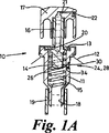
図1A及び1Bは、本発明に従うディスペンサーの一部を形成するオス型エアロゾルバルブ10を示す。バルブ10は、エアロゾル容器の上面の一部を形成する金属カップ12に取付けられる中空のプラスチック筐体11を有する。当業者によく知られているように、一般的にエアロゾル容器は、分注される溶液であるかもしれない液体製品と、少なくとも一部が製品の上でガスとして存在する高圧ガスとを含む。バルブが開いた時に製品が分注されるよう、高圧ガスは容器を加圧する。例えばブタン、圧縮空気、窒素又は二酸化炭素のようなあらゆる最適な高圧ガスが使用できる。
1A and 1B show a
密封(sealing)ガスケット13は筐体の上端の凹部に位置している。バルブ部材14は筐体内に摺動自在に配置されるとともに、スプリング15によって上方に付勢されている。バルブステム16はバルブ部材から上方に突出し、アクチュエータ/ノズル17に収容されている。筐体の下端はバルブへの入口18を備え、さらに浸漬管19を備えつけている。バルブステム16は中空であり、ステムの底部には、バルブが開いた時に流体がバルブ筐体から出てステムに入るよう孔20が備えられている。
A sealing
図1Aに示すように、ディスペンサーが動作していない時、ガスケットによって孔20が密閉されバルブが閉じられるよう、バルブ部材はスプリングによって上方位置に付勢される。しかし、アクチュエータ/ノズル17に下方への圧力が加えられると、図1Bに示すように、孔20が露出するよう、スプリングの付勢に逆らってバルブ部材14が筐体内を下方に移動する。アクチュエータ/ノズルの出口オリフィス22からエアロゾル又はスプレー状に分注される前に、製品は高圧ガスと共に孔20を通ってステムに入り、そこからアクチュエータ/ノズル内の出口通路21に入る。
As shown in FIG. 1A, when the dispenser is not operating, the valve member is biased to an upper position by a spring so that the
液体の噴霧化を助けるため、VPT24が筐体11の側壁に形成され、液体製品がバルブ10を通過する時に、容器内の液体製品上部にあるガス状高圧ガスがVPTを通って液体製品中に導入又は流入可能になっている。VPT24は筐体11の側壁を貫く小孔又は開口26を有し、それを通ってガス状高圧ガスがバルブ筐体内の液体製品に入ることができる。さらにVPT24は、VPT24を通るガスの流量が容器内の圧力変化に応答するよう調整するように構成される流量調整装置28を有する。
In order to assist in the atomization of the liquid, when the VPT 24 is formed on the side wall of the
流量調整装置28は、VPT開口26の周りの筐体11の外面壁に形成される拡張凹部又はチャンバー32に配置される流量調整要素30を含む。この実施形態において、流量調整要素30は、円形の凹部32内を自由に動く円盤状シャトル(shuttle)の形をとる。バルブ10が開いた時に開口26を通るガスの流れを規制するよう、凹部32を貫流するガスの圧力によって要素30が凹部の内端壁34に向かって押圧される。流量調整要素は、凹部の外端の周りに形成されて内側に突出する縁部36によって凹部の内部に保持されるが、要素30を保持するあらゆる最適な手段を用いることができる。
The
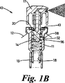
流量調整要素30は実質的に平坦な内面38を有し、この内面は、VPT開口26が形成される凹部の内端壁又は下流端壁34の対応する平面に対向する。図1A及び1Bに示すように、開口を完全に覆い、かつ少なくとも内端壁34の一部と重なるよう、流量調整要素30の外径はVPT開口26の外径より大きい。しかし、高圧ガスが流量調整要素30と内端壁34との間を通ってVPT開口26を経てバルブ筐体内へ入ることができるよう、適切な設計と材料の選択により、流量調整要素30が端壁34と完全なシールを形成しないよう配置することができる。
The
要素30が端壁34に向かって押される力は、開口26を横切って働く圧力差(すなわち、筐体の外側のガスと筐体内を流れる液体製品との間の圧力差)に比例する。ディスペンサーが一杯で容器内の圧力が最大の時、開口を横断する圧力差は比較的高く、かつ、流量調整要素30は、壁面と緊密で部分的なシールを形成すると共にVPT開口26を通る高圧ガス流に対して比較的高い抵抗を示すのに相当する強い力で端壁34に向かって押される。ディスペンサーが空になり容器内の圧力が低下すると、バルブが開いた時にVPT開口26を横断する圧力差も低下する。その結果、流量調整要素30を内端壁34に向かって押す力は低下し、高圧ガスはより容易に流量調整要素30と内端壁34との間を通過できる。このように、容器内の圧力が比較的低い時よりは容器内の圧力が比較的高い時に、流量調整装置28はVPT開口を通るガス流に対して高い抵抗を示す。
The force with which
容器内の圧力が比較的高く、噴霧化を確実にするために液体にガスを流入させる必要が少ない時にガス流を制限することにより、流量調整装置28はVPT24を通る高圧ガス全体の損失を低減するのに寄与する。しかし、容器内の圧力が低下した時、ノズルを通って流れる際に液体の適切な噴霧化を確実にすることに関し、液体に対するガスの比を充分に高くするため、充分なガスがVPTを貫流するように装置28が構成される。VPTを通るガス損失が少ないのと同様に容器内全体の圧力低下も少なくなり、さらにディスペンサーの寿命全体に渡って液体製品の適切な噴霧化を達成するため、又は寿命を延ばすため、適切な設計により容器内に充分な圧力が存在するように配置されることができる。
By restricting the gas flow when the pressure in the container is relatively high and there is little need to allow the gas to flow into the liquid to ensure atomization, the
本実施形態において、容器内で所定の圧力変動の範囲にわたり、VPTを通るガス流量がほぼ一定となるか、又は少なくとも流量調整装置28が無い場合よりガス流が多くなるように流量調整装置28が構成される。しかし実際には、高圧ガスの損失を低減するため、容器内の圧力が比較的高い時にVPTを通るガス流を単に制限すれば十分である。さらに他の場合、容器内の圧力が低下した時にVPTを通るガス流量が増大するよう、流量調整装置28が構成されてもよい。VPTを通る高圧ガスの損失を低減する目的を達成する限り、流量調整装置が複数の方法で構成可能であることは理解されるであろう。例えば、分注される液体製品に対するガスの比がおおむね一定を保つか、又は液体製品に対するガスの比が容器内圧力が低下するにつれて大きくなるよう流量調整装置が構成されることができる。
In the present embodiment, the flow
一実施形態において、開口を横断する圧力差によって2つの対応する平面38、34が互いに押圧された時でさえ、それらが真性の(true)シールを形成できないよう、流量調整要素30と凹部の端壁34内面とは、ポリプロピレン若しくはナイロン(登録商標)プラスチック、金属又はセラミックのような硬質又は半硬質材料から製造される。しかし、より低い圧力差で動作することが要求される、ある用途に関しては、部分的なシールをより簡単に形成できるよう、軟性材料を用いることが適切であろう。
In one embodiment, the
流量調整要素30と凹部の端壁34の内面との間に完全なシールが形成されないことを確実にするため、凹部の内端壁34及び/又は流量調整要素30の面38の対応する表面を粗くしてもよく(textured)、又は内端壁34から流量調整要素30をわずかに間隔をあけさせる他の手段を提供してもよい。その代わりに、凹部の内端壁34の表面及び/又は流量調整要素の面38に溝が形成され、その溝に沿って流体が通ってVPT開口26へ達することができるようにしてもよい。
To ensure that a perfect seal is not formed between the
ある実施形態では、流体が開口26を通って流れる間、流量調整要素34の面38の少なくとも一部は壁34に接している。しかし他の実施形態では、特に要素38と壁34の面が滑らかな場合、面間の流体流がそれらをわずかに離間させる。多くの場合、面38、34間の使用時の隙間は0.01mm未満であるが、特定の状況では隙間が最大0.3mm又は最大0.6mmに至る。使用時の面間の隙間は、バルブ筐体外側のガスと内側の液体との間の圧力差によって決まることは理解されるべきである。容器が一杯又はほぼ一杯であるように圧力差が高い場合、面間の隙間は小さくなるように、流体が通過できる断面積は対応して小さい。容器の内容物が消費されるにつれて圧力差は低下し、かつ、面38、34間の隙間が増大するように流体が開口26を通過して流れることができる断面積も大きくなる。VPTを通る流体の流量は、圧力差と、流体が通過しなければならない最小断面積とによって決まるため、圧力差の減少は、面間の隙間の断面積の増大によって少なくとも部分的に補正され、概して一定の流量が維持される。
In certain embodiments, at least a portion of the
流量調整装置28の設計は、用途のための特定の要求に合うように変更することができる。凹部の内端壁34又は幾つかの場合は側壁と流量調整要素30との間に、制御された方法で高圧ガスがVPT開口26を通過するのを許容する相互作用を形成することが重要である。従って、流量調整要素30と凹部の内端壁34との間のシールは、要求される圧力範囲で部分的であり完全ではないが、VPT開口26を通る高圧ガスの流量が許容範囲内で概して一定であるよう、開口を横断する圧力差(それは同様に容器内圧力に通常は比例する)に伴って事実上(in effectiveness)大きくなる。
The design of the
バルブ10を通る液体製品の流れを調整するため、追加的な流量調整装置(図示せず)をさらに備えることができる。そのため、VPT26を通るガス流量は筐体内の液体と外側のガスとの間の圧力差によって決まる。バルブを通って流れる液体の流量を調整することにより、VPTを通過するガスの流量に影響を与える圧力差も調整される。液体及びガスの両方の流量を調整することは、VPT26を通って流れるガスの流量をより大きく制御することを可能にする。
In order to regulate the flow of the liquid product through the
分注される製品中の液体に対する高圧ガスの比も実質的に一定に維持されるよう、液体製品を実質的に一定流量に保つように追加的な流量調整装置を構成してもよい。その代わり、容器内圧力が低下するにつれて分注される製品中の液体に対する高圧ガスの比が上昇するよう、容器内の圧力が低い時より圧力が高い時に液体製品の流れが増大するような追加的な流量調整装置を構成してもよい。液体とガスとの混合に先立つバルブへの入口、又は出口に追加的な流量調整装置を備えてもよい。追加的な流量装置は、例えば図1A及び1Bに関して上述した流量装置28と同様であってもよいしか、又は以下に記述されるいずれかの変形のようなあらゆる最適な種類であってもよい。
An additional flow regulator may be configured to keep the liquid product at a substantially constant flow rate such that the ratio of high pressure gas to liquid in the dispensed product is also maintained substantially constant. Instead, the addition of increased liquid product flow when the pressure is higher than when the pressure is lower, so that the ratio of high pressure gas to liquid in the product dispensed increases as the pressure in the container decreases. A typical flow control device may be configured. Additional flow control devices may be provided at the inlet or outlet to the valve prior to mixing the liquid and gas. The additional flow device may be similar to, for example, the
その代わり、例えばバルブ自体、又はバルブステム内でバルブの下流、又はノズル、又はバルブとステムの間、又はステムとノズルの間のいずれかで混合された液体とガスの流量を調整するため、流量調整手段の使用により、分注される液体に高圧ガスが流入される割合が調整されてもよい Instead, for example to adjust the flow rate of the liquid and gas mixed either in the valve itself or in the valve stem downstream of the valve, or in the nozzle, or between the valve and stem, or between the stem and nozzle. By using the adjusting means, the ratio of the high pressure gas flowing into the dispensed liquid may be adjusted.
異なる流れ効果を生成するため、及び/又は異なる圧力範囲での装置の使用に適合するため、及び/又は異なる圧力ガスを使用するため、及び液体製品の好ましい流動範囲と特性を満たすため、流量調整装置28の設計は、図1A及び1Bに示されたものから変更することができる。実際には、例えば、好ましい圧力範囲、好ましい流量、及び液体製品と圧力ガスの特性を含むすべての関連する因子を考慮し、流量調整装置28の構造が特定の用途における特定の要望に適合することが期待される。
Flow regulation to produce different flow effects and / or to suit the use of the device in different pressure ranges and / or to use different pressure gases and to meet the preferred flow range and characteristics of liquid products The design of the
図2から図22Bは、本発明に従うディスペンサーの流量調整装置28に使用できる種々の可能な構造を説明する概略図である。これらの図は流量調整装置自体又はその一部のみを示す。示された流量調整装置は、図1A及び1Bに示されたのと同様な方法でバルブ10自体に組み込まれることは理解されるであろう。
2 to 22B are schematic diagrams illustrating various possible structures that can be used in the dispenser
流量調整装置28が圧力範囲の全域でほぼ一定の流れを供給するよう適合させるのと同様に、圧力範囲の全域で異なる流量を供給できるように設計を適合する必要がある。従って、一つの構造が2-10barの圧力で2 l/mの流量を供給する場合、同じ圧力範囲で約3 l/mの流量を供給するためには構造を変更する必要がある。これを達成する単純な方法は、開口が大きくなるほど流量が増えるように、VPT開口26の大きさを変えることである。その代わり、流量をより多くするため、内端壁34に複数のVPT開口26を設けることもできる。図2及び図3は、VPT開口26の大きさが変更された流量調整装置を示し、図4は複数の開口の使用を示す。
Just as the
流量に影響を与え得る他の因子は、凹部32の内端壁34及び/又は流量調整要素の面38の表面仕上げ、並びに内端壁34及び/又は流量調整要素が製造される材料である。従って、粗い又はざらつきのある表面仕上げに比べ、滑らかな表面仕上げは流量を低減させる傾向にある。さらに、上述したように、硬質材料の使用は、流量調整要素30と内端壁34との間の漏れを増加させ、軟質材料が使用された時に得られるのに比べて大きな流量をもたらす傾向にある。
Other factors that can affect the flow rate are the surface finish of the
装置28を通る流量を調整する他の方法は、流量調整要素30と凹部の内端壁34との間の重なり又は接触面積を変えることである。好ましい流量を得るために要求される重なりは、開口26の大きさ、流量調整要素30と内端壁34の材質、流量調整要素と内端壁34の対応する表面の仕上げ、関連する圧力範囲、及び高圧ガスの特性によって決まる。しかし、一般的に言えば、重なりを変更すると漏れの程度を変えることができ、これらは流量を決定する。約4bar以上の高い圧力では、流れが安定するにつれて重なりが減少するのに対し、より低い圧力では重なり面積が大きくなる必要がある。図5は、図2に示される流量調整装置の重なりに比べ、流量調整要素30と内端壁34との間の重なりが減少された流量調整装置を示す。
Another way of adjusting the flow rate through the
添付した図に示されていないが、凹部内でシャトルが安定するのを確実にしながら重なりを減少させる他の方法は、シャトルの外径を小さくし、凹部の側壁に接するため外側に突出する複数の羽根(vane)を備えることである。示されない更に他の方法は、シャトルの角が凹部の側壁に接するよう四角形状又は三角形状のシャトルを用いることである。 Although not shown in the attached figures, other methods of reducing overlap while ensuring that the shuttle is stable within the recess are a plurality of protrusions that protrude outwardly to reduce the shuttle's outer diameter and contact the sidewalls of the recess. Of vane. Yet another method not shown is to use a square or triangular shuttle so that the corners of the shuttle touch the sidewalls of the recess.
図6に示される更に別の設計選択は、凹部の内端壁34に向き合う流量調整要素30の面38に、円形の凹部40を備えることである。これは、流量調整要素と壁との間の接触面積又は重なりを低減し、流量を増加させる傾向にある。さらに、凹部40は、開口26を通過する時にスプレー又は噴流を生じさせる回転を高圧ガスに与える渦チャンバーとして使用することができる。この効果を補助するため、ガスが凹部40に入った時に既に回転しているよう、流量調整要素が位置する凹部の周りにガスが回転させられる。このことは、バルブの外側から凹部32に接線方向への流入を用いること、又は流量調整要素から上流にある公知の渦装置を用いることによって達成される。その代わり又はそれに加え、高圧ガスに回転を起こしバルブ内の液体に円錐形のスプレー又は噴流を生じさせるため、円形の凹部40又はVPT開口26の一部の内側及び周囲に、湾曲した羽根(図示せず)を配置することができる。壁に1以上のVPT開口26がある場合、複数の凹部40を備えることができ、各凹部は開口の各1個に対する渦チャンバーとして動作する。凹部40はあらゆる最適の形状とすることができる。
Yet another design choice shown in FIG. 6 is to provide a
図7は、凹部32及び流量調整要素30が内端壁34に向かって内側に先細る(tapering)円錐又は截頭円錐(frusto-conical)形状の流量調整装置を示す。この装置において、ガスに回転を起こし、VPT開口26を通して円錐形のスプレー又は噴流を生じさせるため、凹部の側壁42又は流量調整要素30の側部44にらせん構造(図示せず)を適用することができる。他の実施形態において(図示せず)、流量調整要素30の円錐状側部44と凹部32の側壁42との間を流体が通過するよう、凹部32の内端壁34が省略されてもよい。この実施形態では、要素30の側壁と流路の側壁42とは対応する面を有し、ガスはこの面の間を通ってVPT開口に達する。この実施形態に使用される流量調整要素30は、添付した図に示された任意のもののような、あらゆる最適の形状とすることができる。さらに、高圧ガスが流量調整要素に達する前、又は流量調整要素に達した後若しくは流量調整要素の周りにある時に、高圧ガスに回転を起こすように渦装置が用いられてもよい。特定の用途においては、流量調整要素と凹部の円錐状側壁42との間の境界線(thin line)に沿って部分的なシールが形成されると都合がよい。このことは、例えば流量調整要素30の側部44を先細りにしないことによって達成することができる。
FIG. 7 shows a flow control device in the form of a cone or frusto-conical with the
図8は、流量調整要素30の面38に円錐状凹部46が形成され、対応する円錐状凹部48がVPT開口26周囲の凹部の内端壁34に形成された装置を示す。この装置は、流量調整要素30と凹部の内端壁34との間から高圧ガスが流入する膨張チャンバー50を形成する。壁34が複数のVPT開口26を有する場合、対応する個数の凹部を流量調整要素の面38及び/又は壁34が有し、各開口に対して膨張チャンバー50を提供することができる。通常、開口26は、それらの各チャンバーの中心に配置される。膨張チャンバー50はあらゆる最適の形状とすることができる。
FIG. 8 shows a device in which a
図9に示すように、流量調整要素30から柱52が突出し、VPT開口26に挿入されてもよい。柱52と開口の側部との隙間が小さい場合、隙間を通過する際にガスが液体中にスプレー又は噴流を形成する。一続きの微細な溝をVPT開口26の内側の周囲又は柱52の表面に備えることができ、この溝は柱と開口26によって規定される壁との間に複数の半円状の開口を効果的に形成し、この開口はバルブ筐体11の内側で複数の微細なスプレー/噴流オリフィスとして機能する。柱52はVPT開口26と隣接(flush with)し、柱52と開口26の外周はいずれも円錐形とすることができる。
As shown in FIG. 9, a
流量調整要素30の面38と凹部の内端壁34とは平坦であってよいが、部分的なシールのみが形成され、かつ流量を変えることを確実にする特定の方法でそれらを形成することができる。図10は、流量調整要素30の面38が凸面状である流量調整装置28を示すが、他の形状を使用することができる。流量調整要素30及び/又は凹部の端壁34の形状変更は、異なる方法でガスをバルブ筐体に導入するために用いることができる。
The
図11は、流量調整要素30が凹部の一端の壁に沿って接続されたフラップ(flap)状をなす流量調整装置を示す。図11に示すように、容器内で圧力をかけられていない時、フラップは通常は凹部の端壁34から少し浮いた位置をとるが、使用時には容器内の圧力により、壁に接触又は近接するように押圧されるよう構成される。しかし、フラップが常に壁34に接触又は近接するよう配置されるが、流量を調整するため、フラップ上に働く流体圧力が上昇するにつれてフラップと壁の間に形成されるシールの効果が増大するようにフラップを構成することができる。
FIG. 11 shows a flow control device in the form of a flap in which the
上記したように、流量及び他の流れ特性を変えるため、流量調整要素30及び/又は壁34の表面仕上げを変更することができる。例えば、最小限の空隙を維持し、フィルターとして機能することを確実にするため、一続きの微小な棒を壁34又は流量調整要素30の面38から突出させることができる。その代わり、溝を壁34及び/又は流量調整要素の面38に形成することができる。溝は、少なくとも最小限のガス流が存在することを確実にし、ガスがVPT開口26を通って液体中にスプレーされるよう、ガスに特定の流れ特性を与えるように溝を配置することができる。
As noted above, the surface finish of the
図12〜図14は、使用され得るいくつかの溝配置の例を示す。これらの図は流量調整要素30の面38を示し、内部円54は凹部の内端壁34にあるVPT開口26の位置を示す。溝は、流量調整要素30の端面38よりむしろ凹部の壁34に形成されるが、必要に応じて両方に形成してもよいことは理解されるべきである。
12-14 show examples of several groove arrangements that may be used. These figures show the
図12において、VPT開口26より大径の円形溝56は、流量調整要素30及びVPT開口26の中心に導かれる複数のスポークに似た放射状溝58を有する。この配置により、ガスは円形溝56に集められた後、放射状溝58に沿ってそれらの内部端に向かい、そこでガスは一連の微小スプレー又は噴流としてVPT開口26に入る。流量調整要素の端面38及び壁34が円錐形である場合、ガスは外側にスプレー又は噴出されてバルブ筐体に入り、種々のスプレー/噴流が互いに衝突し又は必要に応じて互いに逸れるよう方向付けられる。
In FIG. 12, the
図13において、外側円形溝56は、それぞれ異なる大きさであってもよい2つの直線放射状溝62、64によって中心凹部60に接続される。放射状溝62、64は、VPT開口26の異なる側の上にある中心凹部に非接線方向に入るよう配置され、その結果、ガスがVPT開口26に入る際に旋回するよう中心凹部60内でガスが回転させられる。
In FIG. 13, the outer
図14では、外側円形溝56は2つの湾曲した放射状溝66、68によって中心凹部60に接続され、それらの溝は、ガスがそこからVPT開口26を通過する凹部内で回転する渦チャンバーのように、ガスを中心凹部に接線方向に導く。
In FIG. 14, the outer
あらゆる最適な溝の形態が流量調整要素30及び/又は壁34の表面に適用され得る。壁に溝が形成される場合、流体が溝に到達するため要素30と壁34の間を通らなければならないよう、流量調整要素30は通常、すべての溝を覆う。
Any optimum groove configuration may be applied to the
図15A及び図15Bに示される実施形態は、自己洗浄式VPTを形成するための一体スプリングを形成するため、どのように調整要素30を変更するかを説明する。調整要素の本体部分70は皿状で、開口26を伴う壁34の内面に対向する凹面38を有する。図15Bに示すように、既に記述した方法で流量調整装置として動作するよう、本体部分は凹部32を通って流れるガスの圧力により壁34にぶつかって圧縮される。バルブ10が閉じられてVPT26を通るガス流が止まると、図15Aに示すように本体部分70が皿状に戻り、流量調整要素30と壁34との間に捕捉されたあらゆる異物が取り除かれる。図で示すように流量調整要素30は、開口26内に突出する中央柱52を有してよいが、これは省略されてもよい。バネ作用が一般の硬質材料の場合より長く保持されるよう、流量調整要素30又は皿状の本体部分70の少なくとも一部は、可撓性で弾性のある材料で製造されてもよい。
The embodiment shown in FIGS. 15A and 15B illustrates how the
図16A及び図16Bに示される実施形態において、流量調整要素30は、壁34のVPT開口26内に延びる中央柱52を有するだけでなく、壁34に接する要素の面38上に渦誘起構造72も備えている。要素30の端面図である図16Bに示されるように、渦構造72は、柱52を囲む円形凹部74にガスを導入する2つの湾曲した溝を含み、その結果ガスが柱の周りに旋回してVPT26を通過する際に円錐形を形成する。開口26内の柱52の高さは円錐の形状に影響を与える。従来の渦装置とは異なり、VPT開口26を通って流れる流体の流量を調整するため、調整要素30は壁34に対して移動することができる。バルブ筐体に入る前にガスを旋回させることは、筐体内でガスと液体とを混合することを促進し、次にノズル出口で形成される最終スプレーの品質改善を促進する。
In the embodiment shown in FIGS. 16A and 16B, the
好ましい流量調整装置を形成するため、ここに記述された実施形態に示されるあらゆる種々の特徴は、あらゆる最適な方法で組み合わせることができることは理解されるべきである。例えば、図17A及び図17Bは、図15A及び図15Bに関して上述された皿状調整要素30の特徴と、図16A及び図16Bに関して上述されたのと同様にして壁42に接する要素の面38上に形成された渦誘起溝72の特徴とを組み合わせた実施形態を示す。
It should be understood that any of the various features shown in the embodiments described herein can be combined in any optimal manner to form a preferred flow regulator. For example, FIGS. 17A and 17B illustrate the features of the dish-shaped
要素30の面38は平坦である必要はなく、図18、19、20A及び20Bは、凹部の端壁34と連携する先細り面38を調整要素30が有する実施形態を示す。図18に示される実施形態において、調整要素の先細り壁38が、開口26の角で壁34と部分的な点状(point)又は線状(line)シールを形成するよう、凹部32の端壁34は平坦になっている。図19の実施形態において、壁34は、流量調整要素の先細り面38に結合する、対応する先細り壁面76を開口26の周りに有する。図20A及び20Bは、図16A及び図16Bに関して上述されたのと同様な渦装置72が流量調整要素の先細り面38上に形成されたこと以外は図19と同様な実施形態を示す。渦誘起溝72は、流量調整要素30の上から見た端面図である図20Bに最もよく示される。
The
図21A及び図21Bは、流量調整要素が壁34に接する面38上に形成された溝78を有する実施形態を示す。図21Bは、壁34に接する環状部分82によって囲まれる中央凹部80を有する流量調整要素30の端面図である。流体が溝を通って中央凹部に入りVPT開口26を通って出るよう、溝78は環状部分82の両側を横切って延びる。さらに調整要素30は、凹部中央から壁34内の開口26に突出する柱52を有するが、柱は省略されてもよい。要素30が押圧されて壁と接した時に溝78が部分的につぶれて流れに抵抗するよう、調整要素30は可撓性材料から製造されてもよい。要素30を押圧して壁34に接しさせる力が強くなるほど、溝はつぶれてガス流にさらに抵抗するようになる。ガスが流れる溝の最小断面積は、要素を端壁34に付勢する力の関数として変化するため、この装置は開口26を通るガスの流量を調整するために使用することができ、付勢力それ自体が開口26を横断して作用する圧力差の関数である。その代わりの装置において、部分的に溝を埋めて開口を通る流れを規制するため、要素が端壁34にぶつかって圧縮した時に流量調整要素の可撓性材料が溝に押込まれるよう、壁34の内面に溝を形成することができる。使用時に溝?が開口26と流体接続する限り、溝78が流量調整要素の平坦面38に形成されるよう、中央凹部は大きさを縮小し又は完全に無くすことができる。
21A and 21B show an embodiment in which the flow adjustment element has a
流量調整要素30が配置される凹部32は、あらゆる最適な形状とすることができ、特に、その全内容が参照としてここに組み込まれている本出願人の係属中の国際特許出願公開番号WO2005/005055に開示されたあらゆる形状のチャンバーとすることができる。このように、上記したあらゆる実施形態におけるあらゆる凹部の形状は、WO2005/005055で議論された原則に従って変形することができる。同様に、凹部40又は膨張チャンバー50が流量調整要素30と壁34との間に備えられる場合、それら凹部又はチャンバーはWO2005/005055に開示されたものを含むあらゆる最適な形状とすることができる。
The
多数の微小なVPTは、溶液中でのガスの混合を向上させ、最終的に細かいスプレーが形成されるが、このような微小な孔を製造するのは難しい。しかし、ここに記述されたようにVPT24が流量調整装置28を含む場合、従来のVPTに比べてVPT孔又は開口26を大きくすることができ、製造を容易にする。
Many micro VPTs improve the mixing of the gas in the solution and eventually a fine spray is formed, but it is difficult to produce such micro holes. However, if the VPT 24 includes a
装置を通る流体の流路を防止し、又は少なくとも最小限にする一方で、ガスのみを通過させるように流量調整装置28を設計することも可能である。このことは、ガスのみが通過できるような緊密な部分シールを流量調整要素30が壁34と形成するよう、装置を構成することによって達成できる。この装置では、流量調整要素30及び/又は壁34は、良好なシールを形成するゴムのような可撓性材料から製造されるか、又は被覆されてもよい。この装置では、流量調整要素30が接する壁34は膜に相当する細かい網(mesh)の形態をとってもよい。
It is also possible to design the
上記した実施形態の幾つかに示すように、ガスの流量を調整することに加え、筐体内でガスを旋回及び/又は噴流させるように流量調整装置28を設計することができる。このことは、ガスと液体の混合を促進し最終スプレーの品質を向上させるのに役立つ乱流を筐体内で増大させるため有利である。
As shown in some of the embodiments described above, in addition to adjusting the gas flow rate, the
ここに記述される種々の実施形態のさらなる長所は、流量調整装置28が自己洗浄することである。バルブが閉じられて筐体内外の圧力が等しくなった時に、要素30は端壁34及び開口26から離れることができる。このことは、詰りを防止するため、要素30と端壁との間に捕捉されたあらゆる微細粒子をVPTから落下させてきれいにすることを可能にする。大きなVPT孔の使用によって本実施形態における開口26を標準のVPT開口より大きくすることができる能力は、加圧下でバルブ11とVPT開口26を通ってガスが注入されるにつれて容器がガスで満たされた時に、流量調整要素30を端壁34から離間させるために利用することができる。
A further advantage of the various embodiments described herein is that the
さらに別の変形では、凹部の端壁34から見て外側に向く流量調整要素30の外端は、バルブ11からVPT開口26を通って破片が入ることを防止するフォルターを形成するように構成することができる。このように外端は、ガスは通過できるが殆どの異物粒子を捕捉するのに十分な小ささである多数の微細なスリット又は孔を有する円錐形又は扇形部分を備えることができる。円錐形又は扇形部分は外側に延びて、凹部32の側壁に接してもよい。
In yet another variation, the outer end of the
必要とする特性を備えるため、流量調整要素30は複合材料から製造されてよい。例えば、要素はバイインジェクション(bi-injection)成形技術を用いて2又はそれ以上の異なる材料から製造されてもよい。従って、シールを形成するため、流量調整要素は壁に接する可撓性外側部分を有する硬質な芯を含むように製造することができる。さらに、互いを押すか、又は凹部の中にある1つ(の要素)で押すか、又は形成された開口を押すか、又は他の要素30を通って押すよう、2又はそれ以上の流量調整要素が同じ凹部に直列に(in series)用いられることができる。
In order to have the required properties, the
本発明は、この出願に記述されたタイプの流量調整装置28を含むディスペンサーに限定される必要はなく、液体が分注されるにつれて液体中に導入される高圧ガスの流量を調整するためのあらゆる最適な流量調整装置を組み込み可能なことは理解されるであろう。流量調整装置は必ずしも筐体の側壁に備えられる必要はなく、入口を囲むベース領域のような筐体のどこにでも備えられることも理解されるであろう。実際に流量調整装置は、バルブステム内を含むバルブ内のどこにでも、又はバルブへの付加部分のどこにでも備えられることができる。例えば、ディスペンサーが傾けられ又はひっくり返された時により有効に動作できるよう、浸漬管に取付けられ又はそれと一体の傾き(tilt)装置にディスペンサーが取付けられる場合、流量調整装置は傾き装置に備えられてもよい。傾き装置の種々の実施形態のより詳細な記述については、読者は本出願人の国際特許出願WO2004/022451を参照すべきであり、その全内容は参照としてここに組み込まれている。
The present invention need not be limited to a dispenser that includes a
さらに、本発明はここに記述されるタイプのバルブ10を有するディスペンサーの使用に限定されず、あらゆる最適な形態のバルブを有するエアロゾルディスペンサーに適用可能である。例えばバルブは、メス型、又はバルブ内で高圧ガスと液体が分離されたままでノズル内又はバルブステム内で混合されるタイプの分割(split)バルブとすることができる。後者の場合、流量調整装置は、ステム内、ステムとノズルの間、又はノズル自体の内部に位置することができる。本発明はさらに、可撓性の袋によって容器内で高圧ガスが液体製品から分離されたエアロゾルディスペンサーに適用可能である。例えば、あるディスペンサーでは液体製品が伸縮性のある、又は伸縮自在な袋に収容され、袋が一杯になった時に袋自体と容器の外壁との間で空気を圧縮するために袋が膨らむ。ディスペンサーバルブが開いた時、圧縮空気は高圧ガスとして作用し、袋を圧搾すると共に加圧下で内容物にバルブを通過させる。
Further, the present invention is not limited to the use of a dispenser having a
本発明は、現在のところ最も実用的で好ましいと考えられる実施形態に関して記述されてきたが、本発明は記述された装置に限定されず、本発明の精神と範囲に含まれる様々な変形及び均等な構造に及ぶことを意図するのは理解されるであろう。又、VPTと、VPTを通る高圧ガスの流量を調整する流量調整装置とを含むエアロゾルディスペンサーのためのバルブが特許請求の範囲となることも注目すべきである。 Although the present invention has been described with reference to the most practical and preferred embodiment at present, the invention is not limited to the described apparatus and various modifications and equivalents falling within the spirit and scope of the invention. It will be understood that it is intended to cover a wide range of structures. It should also be noted that a valve for an aerosol dispenser that includes a VPT and a flow regulator that regulates the flow of high pressure gas through the VPT is claimed.
含む("comprise", "comprises", "comprised", "comprising")という用語がこの明細書で使用される場合、言及される定まった特徴、完全なもの(integer)、方法又は構成要素の存在を特定するものとして説明されるが、1又はそれ以上の他の特徴、完全なもの、方法、構成要素又はそれらの組合せの存在又は追加を除外するものではない。 When the terms include ("comprise", "comprises", "comprised", "comprising") are used in this specification, the presence of the defined feature, integer, method or component referred to It is not intended to exclude the presence or addition of one or more other features, perfections, methods, components, or combinations thereof.
Claims (27)
前記ディスペンサーは、前記容器からの前記液体製品の放出を調整するためのバルブと、該バルブの筐体内に設けられ、分注される際に前記液体製品内に前記ガス状高圧ガスの一部を導入する1又はそれ以上の細孔からなる気相栓とを有し、
前記ディスペンサーはさらに、前記容器内の内容物の圧力に依存して、前記高圧ガスが前記気相栓を通って前記液体製品内に導入される割合を変えるための流量調整手段を有し、
前記流量調整手段は、前記ディスペンサーの寿命にわたって該ディスペンサー内の圧力が減少するにつれ、分注される液体製品に対する高圧ガスの比が増大するよう構成されることを特徴とするエアロゾルディスペンサー。An aerosol dispenser comprising a container suitable for containing a liquid product to be dispensed and a high pressure gas at least partially present in the container as a gas,
The dispenser is provided with a valve for adjusting the discharge of the liquid product from the container, and a part of the gaseous high-pressure gas in the liquid product when dispensed. Having a gas phase stopper consisting of one or more pores to be introduced,
The dispenser further comprises flow rate adjusting means for changing the rate at which the high pressure gas is introduced into the liquid product through the gas phase stopper depending on the pressure of the contents in the container,
An aerosol dispenser, wherein the flow rate adjusting means is configured to increase the ratio of high pressure gas to liquid dispensed as the pressure in the dispenser decreases over the life of the dispenser.
Applications Claiming Priority (9)
| Application Number | Priority Date | Filing Date | Title |
|---|---|---|---|
| GB0504708.9 | 2005-03-08 | ||
| GB0504708A GB0504708D0 (en) | 2005-03-08 | 2005-03-08 | Flow control apparatus |
| GB0506874A GB0506874D0 (en) | 2005-04-05 | 2005-04-05 | Flow control apparatus |
| GB0506874.7 | 2005-04-05 | ||
| GB0511915.1 | 2005-06-11 | ||
| GB0511915A GB0511915D0 (en) | 2005-06-11 | 2005-06-11 | Aerosol dispenser |
| GB0523461.2 | 2005-11-18 | ||
| GB0523461A GB2432406A (en) | 2005-11-18 | 2005-11-18 | Aerosol valve |
| PCT/GB2006/000794 WO2006095153A1 (en) | 2005-03-08 | 2006-03-07 | Aerosol dispenser |
Publications (3)
| Publication Number | Publication Date |
|---|---|
| JP2008532858A JP2008532858A (en) | 2008-08-21 |
| JP2008532858A5 JP2008532858A5 (en) | 2009-04-30 |
| JP5052494B2 true JP5052494B2 (en) | 2012-10-17 |
Family
ID=36263978
Family Applications (1)
| Application Number | Title | Priority Date | Filing Date |
|---|---|---|---|
| JP2008500255A Expired - Fee Related JP5052494B2 (en) | 2005-03-08 | 2006-03-07 | Aerosol dispenser |
Country Status (10)
| Country | Link |
|---|---|
| US (1) | US7926741B2 (en) |
| EP (1) | EP1858777B1 (en) |
| JP (1) | JP5052494B2 (en) |
| AT (1) | ATE443678T1 (en) |
| AU (1) | AU2006221848A1 (en) |
| BR (1) | BRPI0608688A2 (en) |
| DE (1) | DE602006009377D1 (en) |
| ES (1) | ES2334160T3 (en) |
| MX (1) | MX2007010876A (en) |
| WO (1) | WO2006095153A1 (en) |
Families Citing this family (24)
| Publication number | Priority date | Publication date | Assignee | Title |
|---|---|---|---|---|
| US7677420B1 (en) | 2004-07-02 | 2010-03-16 | Homax Products, Inc. | Aerosol spray texture apparatus for a particulate containing material |
| US7487893B1 (en) | 2004-10-08 | 2009-02-10 | Homax Products, Inc. | Aerosol systems and methods for dispensing texture material |
| MX2007010876A (en) * | 2005-03-08 | 2007-12-06 | Leafgreen Ltd | Aerosol dispenser. |
| GB0702398D0 (en) * | 2007-02-08 | 2007-03-21 | Leafgreen Ltd | A valve for a pressurised dispenser and a pressurised dispenser containing such a valve |
| US8344056B1 (en) | 2007-04-04 | 2013-01-01 | Homax Products, Inc. | Aerosol dispensing systems, methods, and compositions for repairing interior structure surfaces |
| US9382060B1 (en) | 2007-04-05 | 2016-07-05 | Homax Products, Inc. | Spray texture material compositions, systems, and methods with accelerated dry times |
| US8201713B2 (en) * | 2008-04-14 | 2012-06-19 | The Procter & Gamble Company | Pressure compensation member |
| WO2011008840A1 (en) * | 2009-07-15 | 2011-01-20 | The Procter & Gamble Company | Pump dispenser with dip tube having wider tip portion |
| DE102010017669B4 (en) * | 2010-06-30 | 2019-01-03 | Lindal Dispenser Gmbh | Valve for a pressure vessel |
| US9821324B2 (en) * | 2011-04-19 | 2017-11-21 | Dlhbowles, Inc. | Cup-shaped fluidic circuit, nozzle assembly and method |
| US9067221B2 (en) | 2013-03-29 | 2015-06-30 | Bowles Fluidics Corporation | Cup-shaped nozzle assembly with integral filter structure |
| FR2975914B1 (en) * | 2011-06-06 | 2014-07-11 | Soluscope Sas | MACHINE FOR TREATING A MEDICAL DEVICE |
| US9248457B2 (en) | 2011-07-29 | 2016-02-02 | Homax Products, Inc. | Systems and methods for dispensing texture material using dual flow adjustment |
| US9156042B2 (en) | 2011-07-29 | 2015-10-13 | Homax Products, Inc. | Systems and methods for dispensing texture material using dual flow adjustment |
| EP2570190A1 (en) | 2011-09-15 | 2013-03-20 | Braun GmbH | Spray nozzle for dispensing a fluid and sprayer comprising such a spray nozzle |
| US9156602B1 (en) | 2012-05-17 | 2015-10-13 | Homax Products, Inc. | Actuators for dispensers for texture material |
| US9435120B2 (en) | 2013-03-13 | 2016-09-06 | Homax Products, Inc. | Acoustic ceiling popcorn texture materials, systems, and methods |
| US9776785B2 (en) | 2013-08-19 | 2017-10-03 | Ppg Architectural Finishes, Inc. | Ceiling texture materials, systems, and methods |
| WO2015054462A1 (en) | 2013-10-09 | 2015-04-16 | Massachusetts Institute Of Technology | Aerosol generation for stable, low-concentration delivery |
| USD787326S1 (en) | 2014-12-09 | 2017-05-23 | Ppg Architectural Finishes, Inc. | Cap with actuator |
| MX368467B (en) * | 2015-06-01 | 2019-10-03 | Procter & Gamble | Aerosol hairspray product comprising a spraying device. |
| CN109414712B (en) | 2016-05-03 | 2022-06-17 | Dlh鲍尔斯公司 | Nozzle assembly, method of assembly and two-part fluid nozzle assembly |
| FR3073154B1 (en) * | 2017-11-06 | 2020-09-18 | Lindal France | TWO-PIECE NOZZLE FOR AEROSOL DIFFUSERS |
| JP7034503B2 (en) * | 2020-06-04 | 2022-03-14 | 株式会社サイエンス | Mist spray |
Family Cites Families (15)
| Publication number | Priority date | Publication date | Assignee | Title |
|---|---|---|---|---|
| US3790089A (en) * | 1972-01-27 | 1974-02-05 | J Frangos | Aerosol valve construction |
| US4230243A (en) * | 1978-08-08 | 1980-10-28 | Spitzer Joseph G | Aerosol container with flameless delivery valve |
| CH652468A5 (en) * | 1980-08-06 | 1985-11-15 | Werding Winfried J | SLIDER CONTROLLER FOR USE IN A GAS PRESSURE CONTAINER. |
| JPS59171203A (en) * | 1983-03-18 | 1984-09-27 | Hitachi Ltd | Product detecting circuit for quadrature fm demodulation circuit |
| CA1279042C (en) * | 1986-02-11 | 1991-01-15 | Bespak Plc | Gas pressurised dispensing containers |
| GB8909312D0 (en) * | 1988-11-22 | 1989-06-07 | Dunne Stephen T | Liquid-gas mixing device |
| FR2674774B1 (en) * | 1991-04-08 | 1993-07-16 | Oreal | DEVICE FOR SPRAYING A LIQUID COMPRISING A PRESSURIZED CONTAINER PROVIDED WITH AN ADDITIONAL GAS TAKE VALVE. |
| NL9101009A (en) * | 1991-06-11 | 1993-01-04 | Airspray Int Bv | MIXING CHAMBER FOR MIXING A GASEOUS AND A LIQUID COMPONENT. |
| US5211317A (en) * | 1992-06-18 | 1993-05-18 | Diamond George Bernard | Low pressure non-barrier type, valved dispensing can |
| FR2705323B1 (en) * | 1993-05-17 | 1995-07-28 | Oreal | Diffusion valve for an aerosol container, and aerosol container equipped with such a valve. |
| JPH0962364A (en) * | 1995-08-22 | 1997-03-07 | Nifco Inc | Flow regurating valve |
| MXPA05002483A (en) | 2002-09-06 | 2005-09-30 | Leafgreen Ltd | Dip tube and container. |
| JP4320183B2 (en) * | 2003-02-07 | 2009-08-26 | 株式会社ダイゾー | Continuous micro-injection aerosol products |
| CN1812843A (en) | 2003-07-04 | 2006-08-02 | 英克罗有限公司 | Nozzle arrangements |
| MX2007010876A (en) * | 2005-03-08 | 2007-12-06 | Leafgreen Ltd | Aerosol dispenser. |
-
2006
- 2006-03-07 MX MX2007010876A patent/MX2007010876A/en not_active Application Discontinuation
- 2006-03-07 JP JP2008500255A patent/JP5052494B2/en not_active Expired - Fee Related
- 2006-03-07 US US11/885,622 patent/US7926741B2/en not_active Expired - Fee Related
- 2006-03-07 DE DE602006009377T patent/DE602006009377D1/en active Active
- 2006-03-07 AT AT06726351T patent/ATE443678T1/en not_active IP Right Cessation
- 2006-03-07 ES ES06726351T patent/ES2334160T3/en active Active
- 2006-03-07 WO PCT/GB2006/000794 patent/WO2006095153A1/en active Application Filing
- 2006-03-07 BR BRPI0608688-8A patent/BRPI0608688A2/en not_active IP Right Cessation
- 2006-03-07 EP EP06726351A patent/EP1858777B1/en not_active Not-in-force
- 2006-03-07 AU AU2006221848A patent/AU2006221848A1/en not_active Abandoned
Also Published As
| Publication number | Publication date |
|---|---|
| ES2334160T3 (en) | 2010-03-05 |
| DE602006009377D1 (en) | 2009-11-05 |
| ATE443678T1 (en) | 2009-10-15 |
| AU2006221848A1 (en) | 2006-09-14 |
| US7926741B2 (en) | 2011-04-19 |
| BRPI0608688A2 (en) | 2010-12-07 |
| JP2008532858A (en) | 2008-08-21 |
| US20090020568A1 (en) | 2009-01-22 |
| MX2007010876A (en) | 2007-12-06 |
| EP1858777B1 (en) | 2009-09-23 |
| EP1858777A1 (en) | 2007-11-28 |
| WO2006095153A1 (en) | 2006-09-14 |
Similar Documents
| Publication | Publication Date | Title |
|---|---|---|
| JP5052494B2 (en) | Aerosol dispenser | |
| JP5469069B2 (en) | Fluid dispensing nozzle | |
| US9821324B2 (en) | Cup-shaped fluidic circuit, nozzle assembly and method | |
| TWI573626B (en) | Valve assembly | |
| JPS6312664B2 (en) | ||
| JPH09503730A (en) | Aerosol package with adjustable spray properties | |
| EP1912744B1 (en) | An atomising nozzle and an aerosol canister comprising an atomising nozzle | |
| EP1644127B1 (en) | Nozzle arrangements | |
| US20100044400A1 (en) | Valve for a pressurised dispenser comprising inlet orifices being deformable by the internal pressure | |
| US20100116909A1 (en) | Nozzle and dispenser incorporating a nozzle | |
| JP2008521601A (en) | Nozzle device with vortex chamber | |
| CN101146724A (en) | Aerosol dispenser | |
| CA2750095C (en) | System and method for a two piece spray nozzle | |
| WO2006095163A1 (en) | Nozzle comprising a flow control apparatus | |
| WO2005016548A1 (en) | Nozzle for a spray device | |
| WO2003045573A1 (en) | Nozzle | |
| WO2006059080A1 (en) | A valve for a pressurised dispenser and a pressurised dispenser comprising such a valve | |
| US20170173599A1 (en) | Modular Nozzle Assembly and Fluidic Plate Apparatus and Method for Selectively Creating 2-D or 3-D Spray Patterns | |
| WO2007017626A1 (en) | A nozzle and a dispenser having such a nozzle |
Legal Events
| Date | Code | Title | Description |
|---|---|---|---|
| A521 | Request for written amendment filed |
Free format text: JAPANESE INTERMEDIATE CODE: A523 Effective date: 20090304 |
|
| A621 | Written request for application examination |
Free format text: JAPANESE INTERMEDIATE CODE: A621 Effective date: 20090304 |
|
| A711 | Notification of change in applicant |
Free format text: JAPANESE INTERMEDIATE CODE: A711 Effective date: 20110727 |
|
| A521 | Request for written amendment filed |
Free format text: JAPANESE INTERMEDIATE CODE: A821 Effective date: 20110728 |
|
| A521 | Request for written amendment filed |
Free format text: JAPANESE INTERMEDIATE CODE: A821 Effective date: 20110905 |
|
| A521 | Request for written amendment filed |
Free format text: JAPANESE INTERMEDIATE CODE: A821 Effective date: 20111003 |
|
| A131 | Notification of reasons for refusal |
Free format text: JAPANESE INTERMEDIATE CODE: A131 Effective date: 20111212 |
|
| A601 | Written request for extension of time |
Free format text: JAPANESE INTERMEDIATE CODE: A601 Effective date: 20120312 |
|
| A602 | Written permission of extension of time |
Free format text: JAPANESE INTERMEDIATE CODE: A602 Effective date: 20120425 |
|
| A521 | Request for written amendment filed |
Free format text: JAPANESE INTERMEDIATE CODE: A523 Effective date: 20120511 |
|
| A521 | Request for written amendment filed |
Free format text: JAPANESE INTERMEDIATE CODE: A523 Effective date: 20120528 |
|
| TRDD | Decision of grant or rejection written | ||
| A01 | Written decision to grant a patent or to grant a registration (utility model) |
Free format text: JAPANESE INTERMEDIATE CODE: A01 Effective date: 20120625 |
|
| A01 | Written decision to grant a patent or to grant a registration (utility model) |
Free format text: JAPANESE INTERMEDIATE CODE: A01 |
|
| A61 | First payment of annual fees (during grant procedure) |
Free format text: JAPANESE INTERMEDIATE CODE: A61 Effective date: 20120724 |
|
| R150 | Certificate of patent or registration of utility model |
Free format text: JAPANESE INTERMEDIATE CODE: R150 |
|
| FPAY | Renewal fee payment (event date is renewal date of database) |
Free format text: PAYMENT UNTIL: 20150803 Year of fee payment: 3 |
|
| LAPS | Cancellation because of no payment of annual fees |