JP5045854B2 - Mobile drip stand - Google Patents
Mobile drip stand Download PDFInfo
- Publication number
- JP5045854B2 JP5045854B2 JP2011553640A JP2011553640A JP5045854B2 JP 5045854 B2 JP5045854 B2 JP 5045854B2 JP 2011553640 A JP2011553640 A JP 2011553640A JP 2011553640 A JP2011553640 A JP 2011553640A JP 5045854 B2 JP5045854 B2 JP 5045854B2
- Authority
- JP
- Japan
- Prior art keywords
- drip stand
- movable
- wheelchair
- fixed
- stand according
- Prior art date
- Legal status (The legal status is an assumption and is not a legal conclusion. Google has not performed a legal analysis and makes no representation as to the accuracy of the status listed.)
- Expired - Fee Related
Links
Images



Classifications
-
- A—HUMAN NECESSITIES
- A61—MEDICAL OR VETERINARY SCIENCE; HYGIENE
- A61M—DEVICES FOR INTRODUCING MEDIA INTO, OR ONTO, THE BODY; DEVICES FOR TRANSDUCING BODY MEDIA OR FOR TAKING MEDIA FROM THE BODY; DEVICES FOR PRODUCING OR ENDING SLEEP OR STUPOR
- A61M5/00—Devices for bringing media into the body in a subcutaneous, intra-vascular or intramuscular way; Accessories therefor, e.g. filling or cleaning devices, arm rests
- A61M5/14—Infusion devices, e.g. infusing by gravity; Blood infusion; Accessories therefor
- A61M5/1414—Hanging-up devices
- A61M5/1415—Stands, brackets or the like for supporting infusion accessories
-
- A—HUMAN NECESSITIES
- A61—MEDICAL OR VETERINARY SCIENCE; HYGIENE
- A61G—TRANSPORT, PERSONAL CONVEYANCES OR ACCOMMODATION SPECIALLY ADAPTED FOR PATIENTS OR DISABLED PERSONS; OPERATING TABLES OR CHAIRS; CHAIRS FOR DENTISTRY; FUNERAL DEVICES
- A61G5/00—Chairs or personal conveyances specially adapted for patients or disabled persons, e.g. wheelchairs
- A61G5/10—Parts, details or accessories
- A61G5/1094—Tables, working plates or trays
-
- A—HUMAN NECESSITIES
- A61—MEDICAL OR VETERINARY SCIENCE; HYGIENE
- A61M—DEVICES FOR INTRODUCING MEDIA INTO, OR ONTO, THE BODY; DEVICES FOR TRANSDUCING BODY MEDIA OR FOR TAKING MEDIA FROM THE BODY; DEVICES FOR PRODUCING OR ENDING SLEEP OR STUPOR
- A61M5/00—Devices for bringing media into the body in a subcutaneous, intra-vascular or intramuscular way; Accessories therefor, e.g. filling or cleaning devices, arm rests
- A61M5/14—Infusion devices, e.g. infusing by gravity; Blood infusion; Accessories therefor
- A61M5/1414—Hanging-up devices
- A61M5/1417—Holders or handles for hanging up infusion containers
-
- A—HUMAN NECESSITIES
- A61—MEDICAL OR VETERINARY SCIENCE; HYGIENE
- A61G—TRANSPORT, PERSONAL CONVEYANCES OR ACCOMMODATION SPECIALLY ADAPTED FOR PATIENTS OR DISABLED PERSONS; OPERATING TABLES OR CHAIRS; CHAIRS FOR DENTISTRY; FUNERAL DEVICES
- A61G2203/00—General characteristics of devices
- A61G2203/70—General characteristics of devices with special adaptations, e.g. for safety or comfort
- A61G2203/80—General characteristics of devices with special adaptations, e.g. for safety or comfort for connecting a trolley to a device, e.g. bed or column table
-
- A—HUMAN NECESSITIES
- A61—MEDICAL OR VETERINARY SCIENCE; HYGIENE
- A61M—DEVICES FOR INTRODUCING MEDIA INTO, OR ONTO, THE BODY; DEVICES FOR TRANSDUCING BODY MEDIA OR FOR TAKING MEDIA FROM THE BODY; DEVICES FOR PRODUCING OR ENDING SLEEP OR STUPOR
- A61M2209/00—Ancillary equipment
- A61M2209/08—Supports for equipment
- A61M2209/084—Supporting bases, stands for equipment
Landscapes
- Health & Medical Sciences (AREA)
- Life Sciences & Earth Sciences (AREA)
- Animal Behavior & Ethology (AREA)
- General Health & Medical Sciences (AREA)
- Public Health (AREA)
- Veterinary Medicine (AREA)
- Vascular Medicine (AREA)
- Engineering & Computer Science (AREA)
- Anesthesiology (AREA)
- Biomedical Technology (AREA)
- Heart & Thoracic Surgery (AREA)
- Hematology (AREA)
- Infusion, Injection, And Reservoir Apparatuses (AREA)
- Medical Preparation Storing Or Oral Administration Devices (AREA)
Description
本発明は車椅子と敏速かつ簡易に連結でき、車椅子の移動に伴い同時移動が可能で、また歩行時に安心して移動できる脚部形状を持つ移動型点滴スタンドにおける構造に関するものである。 The present invention relates to a structure of a movable drip stand having a leg shape that can be quickly and easily connected to a wheelchair, can be moved simultaneously with the movement of the wheelchair, and can move with confidence during walking.
従来ある移動型点滴スタンドは四本脚、五本脚ベースに移動用のキャスターが設置され、ベース脚部中央に点滴輸液保持用のセンター支柱を立設されたものが多い。患者が点滴を受けながら、歩行するのには脚部やキャスターが妨げになり歩きにくく、特に手術後の回復期の歩行訓練では安全な歩行ができなく、点滴コンポーネント類の設置で重心が変動して支柱が前に倒れて安全な点滴歩行作業が出来なかった。車椅子の患者に対して点滴作業を行う場合、点滴支柱を車椅子の片側にセットされた専用の車椅子が必要であった。しかし車椅子の重心が片側に偏る為、操縦が困難でかつ多くの医療、点滴コンポーネント類が設置できなかった。車椅子患者は移動時に車椅子のフットレストを跳ね上げて、点滴スタンドの脚部に足をのせて点滴スタンドと連結して、点滴スタンドの支柱を持って、後ろから看護師、又は介護者が車椅子を操縦している。エレベーターへの移乗は看護師又は介護者と点滴を受けている患者とが点滴スタンドを転倒しないように支えて移乗している。多様なサイズの車椅子に移動型点滴スタンドが、車椅子の前にも、後ろにも、安全に簡単に、かつ柔軟に連結でき、患者が車椅子を操縦しても同時移動してくれ、看護師、又は介護者が車椅子の前側にも後ろ側に移動型点滴スタンドを設置して、車椅子を操縦しても同時移動してくれ、看護師、又は介護者が車椅子の操縦のみに専念して、安全に追従してくれる移動型点滴スタンドがない。特許文献2は、患者に負担がかかるし、特許文献4は車椅子の後に連結させて移動型点滴スタンドを接続できるものであるが、車椅子の前方にも後方にも敏速かつ簡易に連結できるものではなかった。特許文献3は車椅子対応ではない。又従来の移動型点滴スタンドは、手術後の回復期に使う複数の医療器具、点滴コンポーネント類が1本の支柱の上下方向に取り付けられているので重心位置が上になり、転倒しやすく、又歩行時前方が見えにくくて安全な歩行が確保できない。又使用後は点滴スタンドの脚部形状が五本脚や四本脚の為、病院内で収納場所をとっていた。
Many conventional mobile drip stands have a four-legged or five-legged base with a moving caster, and a center column for holding a drip infusion at the center of the base leg. Legs and casters are difficult to walk while taking IV drip, and it is difficult to walk, especially during convalescent walking training after surgery, and the center of gravity fluctuates due to the installation of IV components. As a result, the support fell down and I could not perform safe drip walking. When performing an infusion operation on a wheelchair patient, a dedicated wheelchair in which an infusion column is set on one side of the wheelchair is necessary. However, since the center of gravity of the wheelchair is biased to one side, it was difficult to control and many medical and infusion components could not be installed. A wheelchair patient jumps up the footrest of the wheelchair when moving, puts his foot on the leg of the drip stand and connects to the drip stand, holds the drip stand column, and the nurse or caregiver controls the wheelchair from behind is doing. In the transfer to the elevator, the nurse or caregiver and the patient receiving the drip are transferred while supporting the drip stand so as not to fall. A mobile drip stand for wheelchairs of various sizes can be connected safely, easily and flexibly to the front and back of the wheelchair, and the patient can move at the same time even if the patient operates the wheelchair. Or, a caregiver installs a movable drip stand on the front side and back side of the wheelchair, and even if the wheelchair is operated, it moves at the same time. There is no mobile drip stand that will follow.
本発明は以上の点を踏まえ、点滴を受けながら車椅子患者に対して本発明の移動型点滴スタンドと車椅子とが安全確実、敏速、柔軟に連結でき、かつ歩行でも安全を確保でき、歩きやすく、複数の医療器具、点滴コンポーネントを設置しても転倒せず、容易に追加して取り付けられ、病院内で収納場所をとらずにネスティング収納可能な移動型点滴スタンドを課題とする。 The present invention is based on the above points, and the mobile drip stand of the present invention and the wheelchair can be safely and reliably, promptly and flexibly connected to a wheelchair patient while receiving infusion, and can secure safety even when walking, easy to walk, It is an object of the present invention to provide a movable infusion stand that does not fall down even if a plurality of medical instruments and infusion components are installed, can be easily added and attached, and can be stored in a nesting manner without taking up a storage space in a hospital.
点滴作業を受ける患者の歩行領域を十分確保できるために移動型点滴スタンドの基部ベース部は平面視で手前側が開いた形状とし、底面に移動用キャスターを複数設置する。基部ベース上に固定支柱を立設し、略上半分は手前側に位置し、下半分は外側に位置させて上半分の固定支柱に上下調節可能なハンドル部を固定設置することで、下肢空間が確保できて歩行しやすく、かつ固定支柱の上部に複数の点滴コンポーネント類を設置しても、重心の側面位置が基部ベース部の中心になるので安全で転倒防止できる。車椅子の患者に対しては、車椅子の前方に移動型点滴スタンドを縦列位置に設置する場合、車椅子のフットレストの様々な位置、サイズ、角度に対応できるように、本発明の移動型点滴スタンドの基部ベース部の左右両側のパイプ中央部の上面に両端を下方に曲げた水平支持パイプを固着させ、その中央部に固定支柱を立設し、固定支柱下方部に水平支持パイプと平行に回転軸を上下動可能に固定設置して、ジョイント金具を回転軸に勘合し、車椅子と連結しない場合は垂直上方において回転ラッチ接合させ、車椅子と連結する時は手前側の車椅子のフットレストに回転係合可能とする。フットレストの高さ、角度に対してはジョイント金具の回転軸の位置を上下調節して固定する。フットレストの奥行きサイズはジョイント金具の左右線材中央部の横線材が前後移動可能に固定する。また車椅子の後方に縦列位置に設置する場合はジョイント金具を上方へ回転ラッチさせて、車椅子の後ろ車輪の本体フレームに本発明の移動型点滴スタンドの基部ベース部を入れて、移動型点滴スタンドのハンドル高さ位置を調節し、車椅子のハンドルと近接させる事で看護師、又は介護者は車椅子と移動型点滴スタンド双方のハンドル操縦が同時に楽に行える。点滴コンポーネントが容易に追加取り付けられる為に、固定支柱に上下調節可能に固定できる略リング状金具から左右両サイドにコの字状のパイプを平面視略V字状に設置し下方に突出させた点滴コンポーネント保持金具を設置する。また病院内で場所をとらずに収納するため、基部ベース部の構造を平面視で手前側が開いた形状として、ネスティング収納ができる移動型点滴スタンドとする。 In order to secure a sufficient walking area for the patient undergoing the drip operation, the base portion of the movable drip stand has a shape with the front side open in plan view, and a plurality of moving casters are installed on the bottom surface. Lower limb space by installing a fixed support on the base base, with the upper half positioned on the near side and the lower half positioned on the outside, and a handle that can be adjusted up and down fixed on the upper half of the fixed support. Can be secured and easy to walk, and even if a plurality of drip components are installed on the upper part of the fixed column, the side surface position of the center of gravity is the center of the base portion, so that it can be safely and prevented from falling. For wheelchair patients, the base of the mobile drip stand of the present invention can be adapted to various positions, sizes and angles of the wheelchair footrest when the mobile drip stand is installed in a tandem position in front of the wheelchair. A horizontal support pipe with both ends bent downward is fixed to the upper surface of the center part of the pipe on both the left and right sides of the base part, and a fixed support column is erected at the center part. It is fixedly installed so that it can move up and down, and the joint bracket is fitted to the rotating shaft.When it is not connected to the wheelchair, it can be rotated and joined to the top of the wheelchair when it is connected to the wheelchair. To do. For the height and angle of the footrest, the position of the rotation axis of the joint bracket is adjusted up and down and fixed. The depth of the footrest is fixed so that the horizontal wire at the center of the left and right wires of the joint bracket can be moved back and forth. Also, when installing in a column position behind the wheelchair, the joint bracket is rotated and latched upward, and the base part of the mobile drip stand of the present invention is inserted into the main body frame of the wheelchair's rear wheel. By adjusting the handle height position and bringing it close to the wheelchair handle, the nurse or caregiver can easily handle both the wheelchair and the mobile drip stand at the same time. In order to easily add additional drip components, U-shaped pipes were installed in a substantially V shape on the left and right sides from a substantially ring-shaped bracket that can be fixed to the fixed support so that it can be adjusted up and down, and protruded downward. Install the drip component holding bracket. In addition, in order to store without taking up space in the hospital, the structure of the base portion is made open on the front side in a plan view to provide a movable drip stand that can be stored in a nesting manner.
本発明による移動型点滴スタンドでは車椅子患者に対しては点滴スタンドを前側にも、後ろ側にも簡単に連結でき、前側に連結する場合は、車椅子の多様なフットレストに対して、柔軟に係合し、敏速に連結できる為、患者自身が一人で移動可能であり、又患者自身が車椅子を操縦できない場合は、看護師、又は介護者が車椅子の操縦に専念できる。また車椅子の後方に縦列位置に接続する場合も移動型点滴スタンドのハンドル位置を調節し、車椅子のハンドルと近接させて看護師、又は介護者が同時操縦することができる。又歩行訓練が必要な患者に対しては下肢空間が確保でき、歩きやすく、安全にかつ転倒の危険が無く、点滴しながら歩行訓練ができる。固定支柱下部に、左右両側にサイドフレームを設けて、手術後の患者の回復期に医療、点滴コンポーネント類を複数取り付けられる。これらのコンポーネント類は固定支柱の下方に設置できるため重心位置がより下になるため転倒に対して安全なものになる。点滴コンポーネント保持金具は平面視V字上の形状で下方に突出したパイプであるので複数の点滴コンポーネント類を並列設置できるので、重心がより下方になり移動時の転倒に対して安全である。又、脚部や支柱本体フレームがネスティングできる構造であるので、省スペース収納の効果がある。 With the mobile drip stand according to the present invention, the drip stand can be easily connected to the front side and the back side for wheelchair patients, and when connected to the front side, it flexibly engages with various footrests of the wheelchair. In addition, since the patient can move by himself / herself because of the quick connection, the nurse or the caregiver can concentrate on the wheelchair when the patient himself / herself cannot control the wheelchair. Also, when connecting to the column position behind the wheelchair, the handle position of the movable drip stand can be adjusted, and the nurse or caregiver can be operated at the same time close to the handle of the wheelchair. For patients who require walking training, a space for the lower limbs can be secured, walking is easy, and there is no danger of falling, and walking training can be performed while instilling. Side frames are provided on the left and right sides at the bottom of the fixed column, and multiple medical and infusion components can be attached during the recovery period of the patient after surgery. Since these components can be installed below the fixed column, the position of the center of gravity is lower, so that they are safe against falling. Since the drip component holding metal fitting is a pipe projecting downward in a V-shaped shape in plan view, a plurality of drip components can be installed in parallel, so that the center of gravity is further lowered and it is safe from falling during movement. In addition, since the leg portion and the support body frame can be nested, there is an effect of space saving storage.
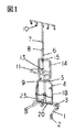
図1は実施例1の移動型点滴スタンド斜視図
図2は実施例1の移動型点滴スタンド平面図
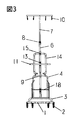
図3は実施例1の移動型点滴スタンド正面図
図4は実施例1の移動型点滴スタンド側面図
図5は実施例1の基部ベース部と固定支柱部斜視図
図6は実施例2の移動型点滴スタンド斜視図
図7は実施例2の基部ベースとコンパクトハンドル平面図
図8はジョイント金具回転軸のストッパー詳細側面図
図9はジョイント金具
図10は固定型ジョイント金具
図11は実施例1の移動型点滴スタンドと車椅子の連結斜視図
図12は実施例2の移動型点滴スタンドと車椅子の連結途中時斜視図
図13は車椅子と実施例1の後ろ位置連結図
図14は実施例1の移動型点滴スタンドのネスティング図
図15は実施例2の移動型点滴スタンドのネスティング図FIG. 1 is a perspective view of a mobile drip stand of Example 1. FIG. 2 is a plan view of a mobile drip stand of Example 1. FIG. 3 is a front view of a mobile drip stand of Example 1. FIG. Side view FIG. 5 is a perspective view of the base portion and the fixed column portion of the first embodiment. FIG. 6 is a perspective view of a movable drip stand of the second embodiment. FIG. 7 is a plan view of the base portion and the compact handle of the second embodiment. Detailed side view of stopper of rotating shaft FIG. 9 is a joint bracket FIG. 10 is a joint perspective view of a movable drip stand and a wheelchair according to the first embodiment, and FIG. 12 is a perspective view of a movable drip stand and a wheelchair according to the second embodiment. FIG. 13 is a connection diagram of the rear position of the wheelchair and the first embodiment. FIG. 14 is a nesting diagram of the movable drip stand of the first embodiment. FIG. 15 is a nesting diagram of the movable drip stand of the second embodiment.
図1〜図4は本発明の移動型点滴スタンドに適した実施例1を示しており、このうち図1は移動型点滴スタンド斜視図、図2は同平面図、図3は同正面図、図4は側面図を示す。図6は本発明の実施例2のコンパクト型基部ベース部とコンパクトハンドルを設置した移動型点滴スタンド、図7はその基部ベース部の平面図、図8はジョイント金具17,18の回転軸20のストッパー21の詳細図、図9は車椅子のフットレストと連結するジョイント金具17、図10はその固定型ジョイン金具18を示す。
本実施例1に係る移動型点滴スタンドの基本構成は、図1に示すように基部ベース部1、キャスター2、水平支持パイプ3、固定支柱6、サイドフレーム4、ハンドル11、可動支柱7、点滴コンポーネント保持金具14、ジョイント金具17または固定型ジョイント金具18とその取り付け部の回転軸20、回転軸固定チャンネル23より構成される。基部ベース部1は平面視で手前側が開いた形状とし本実施例1では図2で平面視が略逆U字形のパイプで手前側が八の字形に開いた形状を成し、底面部に左右対で手前側に2個、先端部両側に2個の合計4個の移動可能なキャスター2を設けている。図5は基部ベース部1の左右両側のパイプ中央の上面に両端を下方に曲げた水平支持パイプ3を固着させ、その中央部に固定支柱6を立設している。固定支柱6は固定支柱支持リング9と水平支持パイプ3の中央部上面に設けたガイドパイプ28に挿入し、ネジで固定されて垂直に設置され、中央部よりやや下方で6cmほど手前側に折れ曲がり、又垂直上方に折れ曲がって、下方の固定支柱6と平行に立設している。以上の構成で重心の平面位置が基部ベース部1に設置した4個のキャスター2位置の略中心になし、かつ歩行者の手前側の下肢空間が確保される。折れ曲がっている下の固定支柱6の上部から左右両側方向にサイドフレーム4を水平に15cmほど伸ばし、下方に屈曲させ水平支持パイプ3の両端部と固着している。図5に示すようにサイドフレーム4の左右水平エンド部両側に医療コンポーネント類を掛けるサイドフレームフック5が設けられていて固定支柱6の前方下部面にその保持面を構成している。サイドフレームフック5は医療コンポーネント類のチューブ類が基部ベース部のキャスター2に絡むのを防ぐために引っ掛けて整理することもできる。
図6では実施例2の基部ベース部とコンパクトハンドル12を持つ移動型点滴スタンドを示す。実施例2の基部ベースは、実施例1の先端のつなぎ部をカットし、八の字状とし、左右のパイプの手前側を実施1より短くして、幅方向を縮小させ、水平支持パイプ3の中央手前側から1本の脚部を手前側に伸ばし、先端部底面を他の4本と同一面になるようにし、各々先端部底面にキャスター2を設置し、図7に示す様に、正五角形に比べ左右パイプの先端部の閉じ角度が正五角形より略15度ほど小さく、変形五角形になるように設置している。変形五角形基部ベースに至っては前後の転倒安定性を保ちつつ、手前側の左右の歩行スペースを確保し歩きやすい形状で、奥行きは略同じで、横幅方向のコンパクト性を向上させた形状を提供する。
図1、図3、図4、図5に示すように固定支柱6の手前最下部にジョイント金具17、18が手前に回転するように、水平支持パイプ3と平行に回転軸20が上下調節可能に固定できるように、回転軸固定チャンネル23を固定支柱6の下部に複数のネジ穴16に固定設置、または固定支柱6のパイプ表面にネジつきハンドルで締め付けて固定設置し車椅子31の多様なフットレスト32の高さ、角度に合うように調節、固定する。図9に示すようにジョイント金具17の基本構成は回転軸固定チャンネル23の下端に固着されている回転軸20に左右線材29が勘合し、可動左右線材30が左右線材29の内側に固着されているガイドパイプ28に勘合して、圧縮バネ27で常に回転軸20のほうに押圧されてセットされている。車椅子と連結しない場合には、ジョイント金具17は垂直上方においてジョイント金具キャッチ24と横線材25が回転ラッチ接合して歩行の邪魔にならない様に下肢空間を得ることができる。車椅子31のフットレスト32と連結する場合には、ジョイント金具17は回転ラッチをはずし、手前側の車椅子31のフットレスト32に固定横線材26の両側の縦材と可動側の可動左右線材30のL字状に曲がった部分で回転係合して連結される。図8に示すように回転軸20はジョイント金具17、18が最下角度以下に回転落下しないように両端部に回転ストッパー21が設けられている。
図9に示すようにジョイント金具17は回転軸20に勘合された左右線材29と固定横線材26は1本の線材で構成され、ガイドパイプ28がそれぞれ左右線材29の内側に固着され、可動左右線材30がガイドパイプ28に沿って、圧縮バネ27を挿入されて回転軸方向の先をネジで固定し、反対側は先端をL字状に下方に曲げて先に球状玉を設けている。車椅子31のフットレスト32の奥行き幅に合致するように可動側の横線材25を前後調節して圧縮バネで圧接できる。図10は別の実施例であり固定型のジョイント金具で左右の線材と横線材の少なくとも3本の線材で構成され、左右の線材は先端をL字状に下方に曲げて先に球状玉を設けて車椅子31のフットレスト32に係合しやすい様に、かつ係合時の患者の足部の安全のために設けている。図9、図10に示すように左右のL字部はお互いに平面視略30度内側に曲げられている。これは車椅子31の前後の移動により車椅子31の前輪34が前方に回動し、その外輪先端部がジョイント金具17、又は固定型ジョイント金具18のL字部と干渉するのを避けるためである。以上で車椅子31のフットレスト32の大きさ、角度、設置高さの違いによる連結が柔軟に可能となる。図9のアジャスト型、または図10の固定型の選択は使用者が設置時に選択できる。ジョイント金具17および固定型ジョイント金具18の左右L字形先端の内側がお互いにつながらずに開いていることで、連結時に車椅子患者がフットレスト32から脚を上げずに連結をしたり、はずしたりすることが出来る。ジョイント金具17および固定型ジョイント金具18と車椅子のフットレス32は略上下動自在に成りえる為に本発明の移動型点滴スタンドと車椅子の連結追従性は剛体的でなく遊動係合しているため、柔軟に追従し、床面の凸凹に対して互いに影響を及ぼさない。また車椅子の前進移動で急停止をした場合、本発明の点滴スタンドは前方に慣性力を受けるがジョイント金具17または固定型ジョイント金具18の回転ストッパー21で下方の回転が止まる為、本発明の移動型点滴スタンドの固定支柱6と前方転倒角度が縮まらないため前方転倒の問題はない。
図1、図3、図4の示すように固定支柱6の上半分にハンドル11を患者の身体状態に合わせる為に、上下調節、固定が出来るようにハンドル調節パイプの左右両サイドに略38cmの全幅を有するリング状のパイプで把持部を設け、固定支柱6に勘合させてハンドル上下調節ノブ13で固定する。
図1の示すように固定支柱6の上半分の支柱内を可動支柱7が上下調節可能に固定設置し、上端にT字形に水平バーを設けその下方に点滴輸液を吊るす吊り下げフック10を設ける。固定支柱部には可動支柱7の高さを調節し固定支柱6と可動支柱7を勘合固定する為のねじ部を固定支柱上端に設け、可動支柱固定ノブ8にて、固定される。
図1、図3、図4に示すように固定支柱6に上下調節可能に固定できる点滴コンポーネント保持金具14は、略リング状金具から左右両サイドにコの字上のパイプを平面視略V字状に設置し、下方に突出させて構成し、固定支柱6と勘合して保持金具上下調節ノブ15にて固定される。複数の点滴コンポーネントは従来の点滴スタンドのように1本の支柱に設置するより左右2本のパイプに設置したほうが重心の位置を低くでき、かつ歩行者や車椅子を操縦する人に対して前方が見えやすく安全に移動ができる。V字状に設置することでハンドル11、コンパクトハンドル12の高さ位置が点滴コンポーネントと干渉することなく設置できる。
車椅子31の前方に本発明の移動型点滴スタンドを連結する場合、図11、図12に示すようにジョイント金具17または固定型ジョイント金具18を上部のジョイント金具キャッチ24から前方に倒し車椅子31のフットレスト部32に上から係合して連結する。このときの車椅子と本発明の移動型点滴スタンドの位置関係は、略基部ベース部1の手前パイプ端部と車椅子31の前輪キャスター34が回転しても接触しない位置関係になる。又車椅子31の動きに対して柔軟に遊動接合し、故意にジョイント金具17、または固定型ジョイント金具18をフットレスト32から持ち上げてはずさない限り、フットレスト32から外れる事はない。
車椅子31の後方に本発明の本体を接合する場合、図13のように車椅子31の後ろ側の本体フレーム、または車椅子31の大車輪35の間に本発明の基部ベース部1を挟み入れ、ハンドル11を車椅子31のハンドル33の高さにあわせて近接させる。車椅子によっては位置関係、サイズにより、図13の様に本発明のハンドル11は略180度回転させた位置に調節してお互いの機器のハンドルを近接させて同時に操縦することが出来る。
歩行可能な患者に対しては、本発明の移動型点滴スタンドからジョイント金具取り付け部全体を固定支柱部6からとりはずして使用できる。点滴コンポーネント保持金具14がいらない患者に対しても取り外すことで重量が軽減でき移動することが楽になる。
本発明の構造はネスティング収納可能な構造であり、病院等での使用後の収納はジョイント金具17または固定型ジョイント金具18を上方にジョイント金具チャッチ24と回転ラッチ接合させた状態で図14、図15のごとく整列して収納できる。1 to 4 show Example 1 suitable for the mobile drip stand of the present invention, in which FIG. 1 is a perspective view of the mobile drip stand, FIG. 2 is a plan view thereof, and FIG. 3 is a front view thereof. FIG. 4 shows a side view. 6 is a movable drip stand having a compact base portion and a compact handle according to a second embodiment of the present invention, FIG. 7 is a plan view of the base portion, and FIG. 8 is a plan view of the
As shown in FIG. 1, the basic configuration of the movable drip stand according to the first embodiment is as follows: base base 1,
FIG. 6 shows a movable drip stand having a base portion of Example 2 and a
As shown in FIGS. 1, 3, 4, and 5, the
As shown in FIG. 9, the joint metal fitting 17 is composed of a left and
As shown in FIGS. 1, 3, and 4, in order to adjust the
As shown in FIG. 1, a
As shown in FIGS. 1, 3, and 4, the drip component holding metal fitting 14 that can be fixed to the fixed
When the mobile drip stand of the present invention is connected in front of the
When joining the main body of the present invention behind the
For a patient who can walk, the entire joint bracket mounting part can be detached from the fixed
The structure of the present invention is a structure capable of nesting storage, and storage after use in a hospital or the like is shown in FIG. 14 and FIG. It can be stored in line as shown in 15.
本発明は医療用の移動型点滴スタンドと多様なサイズの車椅子との連結方法の一案であるが病院内で多忙な看護師、介護士に少しでも本来の仕事に集中すべく、楽に車椅子と連結できる機器類に対して安価でシンプルで柔軟に利用可能である。 The present invention is a proposal of a method for connecting a mobile drip stand for medical use and wheelchairs of various sizes, but in order to concentrate on the original work to nurses and caregivers who are busy in the hospital, It is cheap, simple and flexible for devices that can be connected.
1 基部ベース部
1a 実施例2の基部ベース部
2 キャスター
3 水平支持パイプ
4 サイドフレーム
5 サイドフレームフック
6 固定支柱
7 可動支柱
8 可動支柱固定ノブ
9 固定支柱支持リング
10 吊り下げフック
11 ハンドル
12 コンパクトハンドル
13 ハンドル上下調節ノブ
14 点滴コンポーネント保持金具
15 点滴コンポーネント保持金具上下調節ノブ
16 ジョイント金具高さ調節ネジ穴
17 ジョイント金具
18 固定型ジョイント金具
20 回転軸
21 回転軸ストッパー
22 ジョイント金具上下調節ノブ
23 回転軸固定チャンネル
24 ジョイント金具チャッチ
25 横線材
26 固定横線材
27 圧縮バネ
28 ガイドパイプ
29 左右線材
30 可動左右線材
31 車椅子
32 フットレスト
33 車椅子ハンドル
34 車椅子前輪キャスター
35 大車輪DESCRIPTION OF SYMBOLS 1 Base base part 1a
Claims (7)
Priority Applications (1)
| Application Number | Priority Date | Filing Date | Title |
|---|---|---|---|
| JP2011553640A JP5045854B2 (en) | 2010-11-25 | 2011-04-14 | Mobile drip stand |
Applications Claiming Priority (4)
| Application Number | Priority Date | Filing Date | Title |
|---|---|---|---|
| JP2010277459 | 2010-11-25 | ||
| JP2010277459 | 2010-11-25 | ||
| PCT/JP2011/059773 WO2012070260A1 (en) | 2010-11-25 | 2011-04-14 | Movable iv stand |
| JP2011553640A JP5045854B2 (en) | 2010-11-25 | 2011-04-14 | Mobile drip stand |
Publications (2)
| Publication Number | Publication Date |
|---|---|
| JP5045854B2 true JP5045854B2 (en) | 2012-10-10 |
| JPWO2012070260A1 JPWO2012070260A1 (en) | 2014-05-19 |
Family
ID=46145622
Family Applications (1)
| Application Number | Title | Priority Date | Filing Date |
|---|---|---|---|
| JP2011553640A Expired - Fee Related JP5045854B2 (en) | 2010-11-25 | 2011-04-14 | Mobile drip stand |
Country Status (4)
| Country | Link |
|---|---|
| US (1) | US20130228997A1 (en) |
| JP (1) | JP5045854B2 (en) |
| CN (1) | CN103501836A (en) |
| WO (1) | WO2012070260A1 (en) |
Cited By (2)
| Publication number | Priority date | Publication date | Assignee | Title |
|---|---|---|---|---|
| JP2014097119A (en) * | 2012-11-13 | 2014-05-29 | Takano Co Ltd | Drip infusion stand |
| KR101678467B1 (en) | 2015-01-08 | 2016-11-23 | 박효동 | Easy to Move of Ringer's Stand on Ramps |
Families Citing this family (29)
| Publication number | Priority date | Publication date | Assignee | Title |
|---|---|---|---|---|
| JP5989472B2 (en) * | 2012-09-14 | 2016-09-07 | アトムメディカル株式会社 | Gartle stand |
| JP6071431B2 (en) * | 2012-11-01 | 2017-02-01 | アトムメディカル株式会社 | Gartle stand |
| JP6096476B2 (en) * | 2012-11-13 | 2017-03-15 | タカノ株式会社 | Drip stand |
| WO2014156519A1 (en) * | 2013-03-29 | 2014-10-02 | 泉株式会社 | Intravenous stand |
| CA2916684C (en) * | 2013-07-19 | 2021-11-23 | Firefly Medical, Inc. | Devices for mobility assistance and infusion management |
| JP6200239B2 (en) * | 2013-08-20 | 2017-09-20 | タカノ株式会社 | Drip stand |
| CN103656794B (en) * | 2013-12-17 | 2015-08-05 | 张素平 | A kind of multiplex roller of Mobile infusion device |
| US9119909B1 (en) * | 2014-02-17 | 2015-09-01 | Brian P. DiVito | IV holder |
| JP6367654B2 (en) * | 2014-08-29 | 2018-08-01 | 株式会社トップ | Connecting device |
| US10582981B2 (en) | 2016-02-02 | 2020-03-10 | Stryker Corporation | Accessory support and coupling systems for an accessory support |
| US10369273B2 (en) * | 2016-06-21 | 2019-08-06 | Pedigo Products, Inc. | Interlocking base for mobile stand for use with intravenous delivery of medications |
| USD820978S1 (en) | 2017-03-31 | 2018-06-19 | Pedigo Products, Inc. | Wheeled base |
| USD848003S1 (en) * | 2017-04-07 | 2019-05-07 | Norman Charles Worcester | Medical equipment stand |
| CN107320807A (en) * | 2017-06-30 | 2017-11-07 | 于巧媛 | A kind of Multifunctional one-man infusion stand |
| US10111793B1 (en) * | 2017-07-19 | 2018-10-30 | Garner Sharp Falls | IV pole stand stop |
| US11007102B2 (en) | 2017-08-22 | 2021-05-18 | Stryker Corporation | Patient transport system |
| CN107715220A (en) * | 2017-09-21 | 2018-02-23 | 张志杰 | A kind of medical extension salt water installations |
| CA2986875A1 (en) * | 2017-11-15 | 2019-05-15 | Ridgeline Medical Supply Inc. | Equipment caddy for demountable engagement with a single-pole rolling stand |
| USD884697S1 (en) * | 2017-11-17 | 2020-05-19 | Samsung Electronics Co., Ltd. | Digital board |
| US11471590B2 (en) * | 2020-02-24 | 2022-10-18 | Isaac Schmitt | Telescopic support pole for medical equipment |
| CN111346271A (en) * | 2020-03-12 | 2020-06-30 | 泰信利美信息科技(常州)有限公司 | Shading device for infusion |
| CN111870766B (en) * | 2020-07-31 | 2022-04-15 | 李东烨 | An infusion device for neurosurgery nursing |
| CN112336944A (en) * | 2020-09-28 | 2021-02-09 | 辉瑞(山东)环境科技有限公司 | Remove lift integral type transfusion rod |
| US11766517B2 (en) * | 2021-03-17 | 2023-09-26 | Better Enterprise Co., Ltd. | Insert-storage type intravenous drip moving seat |
| US11918776B1 (en) | 2021-07-02 | 2024-03-05 | Centicare Corporation | Multi-positional handle for intravenous bag stand |
| JP2023137731A (en) * | 2022-03-18 | 2023-09-29 | フクダ電子株式会社 | medical trolley |
| US20240130919A1 (en) * | 2022-10-13 | 2024-04-25 | Board Of Regents, The University Of Texas System | System for gait training |
| US20240374809A1 (en) * | 2023-05-11 | 2024-11-14 | University Of Massachusetts | Intravenous pole for improved safety and accuracy of intravenous medication administration |
| KR102918922B1 (en) * | 2023-08-28 | 2026-01-27 | 최유나 | Easy-to-walk Safe Ringer Pole |
Citations (3)
| Publication number | Priority date | Publication date | Assignee | Title |
|---|---|---|---|---|
| US4511157A (en) * | 1982-07-19 | 1985-04-16 | St. Joseph's Hospital And Medical Center | Apparatus for facilitating intravenous feeding during transportation of patient |
| US4840391A (en) * | 1987-04-20 | 1989-06-20 | Schneider Karl D | Transportation of hospital patients |
| JP2006304925A (en) * | 2005-04-27 | 2006-11-09 | Chest M I Inc | Wheelchair |
Family Cites Families (8)
| Publication number | Priority date | Publication date | Assignee | Title |
|---|---|---|---|---|
| US4225104A (en) * | 1978-11-20 | 1980-09-30 | Larson Godfrey R | Handle for mobile intravenous stand |
| JPH0810414Y2 (en) * | 1990-02-06 | 1996-03-29 | セイレイ工業株式会社 | Grain sorter |
| US5083807A (en) * | 1990-12-18 | 1992-01-28 | Church Home & Hospital Of The City Of Baltimore | IV stand coupling device |
| US5112019A (en) * | 1991-02-04 | 1992-05-12 | Storz Instrument Company | Motorized IV pole assembly |
| US5344169A (en) * | 1992-01-27 | 1994-09-06 | Pryor Products | Multi-pole support stand |
| US5898961A (en) * | 1995-06-07 | 1999-05-04 | Hill-Rom, Inc. | Mobile support unit and attachment mechanism for patient transport device |
| EP1954333A4 (en) * | 2005-11-21 | 2010-03-17 | About Time Technologies Pty Lt | Mobility frame |
| US7967174B2 (en) * | 2008-10-20 | 2011-06-28 | Rene Lauber | Article carrier for an invalid vehicle |
-
2011
- 2011-04-14 JP JP2011553640A patent/JP5045854B2/en not_active Expired - Fee Related
- 2011-04-14 WO PCT/JP2011/059773 patent/WO2012070260A1/en not_active Ceased
- 2011-04-14 CN CN201180035706.6A patent/CN103501836A/en active Pending
- 2011-04-14 US US13/813,193 patent/US20130228997A1/en not_active Abandoned
Patent Citations (3)
| Publication number | Priority date | Publication date | Assignee | Title |
|---|---|---|---|---|
| US4511157A (en) * | 1982-07-19 | 1985-04-16 | St. Joseph's Hospital And Medical Center | Apparatus for facilitating intravenous feeding during transportation of patient |
| US4840391A (en) * | 1987-04-20 | 1989-06-20 | Schneider Karl D | Transportation of hospital patients |
| JP2006304925A (en) * | 2005-04-27 | 2006-11-09 | Chest M I Inc | Wheelchair |
Cited By (2)
| Publication number | Priority date | Publication date | Assignee | Title |
|---|---|---|---|---|
| JP2014097119A (en) * | 2012-11-13 | 2014-05-29 | Takano Co Ltd | Drip infusion stand |
| KR101678467B1 (en) | 2015-01-08 | 2016-11-23 | 박효동 | Easy to Move of Ringer's Stand on Ramps |
Also Published As
| Publication number | Publication date |
|---|---|
| JPWO2012070260A1 (en) | 2014-05-19 |
| WO2012070260A1 (en) | 2012-05-31 |
| US20130228997A1 (en) | 2013-09-05 |
| CN103501836A (en) | 2014-01-08 |
Similar Documents
| Publication | Publication Date | Title |
|---|---|---|
| JPWO2012070260A1 (en) | Mobile drip stand | |
| US7950405B2 (en) | Enhanced patient mobility apparatus | |
| JP4582426B2 (en) | Patient lifting device | |
| US5201087A (en) | Patient presentation | |
| US20100148542A1 (en) | Multi-purpose chair | |
| US20060130238A1 (en) | Bed side rail method and apparatus | |
| CN210812166U (en) | Transfer auxiliary device | |
| US20150202102A1 (en) | Wheelchair with Automatic Seat Lift Mechanism | |
| AU2006315103A1 (en) | Mobility frame | |
| US20040107519A1 (en) | Portable ambulatory assist rail ramp system | |
| CN209734482U (en) | Self-service walking apparatus for rehabilitation nursing | |
| KR20160136755A (en) | Lift equipped with electric wheelchair | |
| JP5313385B2 (en) | Care assist device suitable for use as a device for moving a care recipient and device for assisting walking | |
| CN106309043A (en) | A lathe integrated nursing device | |
| JP6200239B2 (en) | Drip stand | |
| JP2007202880A (en) | Walking implement | |
| JP3202436U (en) | Transfer device | |
| CN204484692U (en) | A kind of rehabilitation walker | |
| CN210542357U (en) | A multifunctional walker for rehabilitation training | |
| JP2009028478A (en) | Cart for body traction type intravenous drip and for oxygen cylinder for both of indoor or outdoor application | |
| CN218187452U (en) | Multifunctional infusion support | |
| CN217525619U (en) | Five-linkage walking lifting device | |
| CN202505629U (en) | Sickbed with multifunctional nursing-assisted frame | |
| CN222172504U (en) | A nursing bed with adjustable direction infusion stand | |
| CN111773471A (en) | A multifunctional infusion stand |
Legal Events
| Date | Code | Title | Description |
|---|---|---|---|
| TRDD | Decision of grant or rejection written | ||
| A01 | Written decision to grant a patent or to grant a registration (utility model) |
Free format text: JAPANESE INTERMEDIATE CODE: A01 Effective date: 20120612 |
|
| A01 | Written decision to grant a patent or to grant a registration (utility model) |
Free format text: JAPANESE INTERMEDIATE CODE: A01 |
|
| A61 | First payment of annual fees (during grant procedure) |
Free format text: JAPANESE INTERMEDIATE CODE: A61 Effective date: 20120702 |
|
| FPAY | Renewal fee payment (event date is renewal date of database) |
Free format text: PAYMENT UNTIL: 20150727 Year of fee payment: 3 |
|
| R150 | Certificate of patent or registration of utility model |
Free format text: JAPANESE INTERMEDIATE CODE: R150 |
|
| LAPS | Cancellation because of no payment of annual fees |