JP5039085B2 - Method and system for controlling setpoints for extracting air from a compressor and supplying turbine cooling air in a gas turbine - Google Patents
Method and system for controlling setpoints for extracting air from a compressor and supplying turbine cooling air in a gas turbine Download PDFInfo
- Publication number
- JP5039085B2 JP5039085B2 JP2009115096A JP2009115096A JP5039085B2 JP 5039085 B2 JP5039085 B2 JP 5039085B2 JP 2009115096 A JP2009115096 A JP 2009115096A JP 2009115096 A JP2009115096 A JP 2009115096A JP 5039085 B2 JP5039085 B2 JP 5039085B2
- Authority
- JP
- Japan
- Prior art keywords
- stage
- air
- compressor
- extracted
- pressure
- Prior art date
- Legal status (The legal status is an assumption and is not a legal conclusion. Google has not performed a legal analysis and makes no representation as to the accuracy of the status listed.)
- Expired - Fee Related
Links
Images


Classifications
-
- F—MECHANICAL ENGINEERING; LIGHTING; HEATING; WEAPONS; BLASTING
- F02—COMBUSTION ENGINES; HOT-GAS OR COMBUSTION-PRODUCT ENGINE PLANTS
- F02C—GAS-TURBINE PLANTS; AIR INTAKES FOR JET-PROPULSION PLANTS; CONTROLLING FUEL SUPPLY IN AIR-BREATHING JET-PROPULSION PLANTS
- F02C9/00—Controlling gas-turbine plants; Controlling fuel supply in air- breathing jet-propulsion plants
- F02C9/16—Control of working fluid flow
- F02C9/18—Control of working fluid flow by bleeding, bypassing or acting on variable working fluid interconnections between turbines or compressors or their stages
-
- F—MECHANICAL ENGINEERING; LIGHTING; HEATING; WEAPONS; BLASTING
- F02—COMBUSTION ENGINES; HOT-GAS OR COMBUSTION-PRODUCT ENGINE PLANTS
- F02C—GAS-TURBINE PLANTS; AIR INTAKES FOR JET-PROPULSION PLANTS; CONTROLLING FUEL SUPPLY IN AIR-BREATHING JET-PROPULSION PLANTS
- F02C6/00—Plural gas-turbine plants; Combinations of gas-turbine plants with other apparatus; Adaptations of gas- turbine plants for special use
- F02C6/04—Gas-turbine plants providing heated or pressurised working fluid for other apparatus, e.g. without mechanical power output
- F02C6/06—Gas-turbine plants providing heated or pressurised working fluid for other apparatus, e.g. without mechanical power output providing compressed gas
- F02C6/08—Gas-turbine plants providing heated or pressurised working fluid for other apparatus, e.g. without mechanical power output providing compressed gas the gas being bled from the gas-turbine compressor
-
- F—MECHANICAL ENGINEERING; LIGHTING; HEATING; WEAPONS; BLASTING
- F02—COMBUSTION ENGINES; HOT-GAS OR COMBUSTION-PRODUCT ENGINE PLANTS
- F02C—GAS-TURBINE PLANTS; AIR INTAKES FOR JET-PROPULSION PLANTS; CONTROLLING FUEL SUPPLY IN AIR-BREATHING JET-PROPULSION PLANTS
- F02C7/00—Features, components parts, details or accessories, not provided for in, or of interest apart form groups F02C1/00 - F02C6/00; Air intakes for jet-propulsion plants
- F02C7/12—Cooling of plants
- F02C7/16—Cooling of plants characterised by cooling medium
- F02C7/18—Cooling of plants characterised by cooling medium the medium being gaseous, e.g. air
Description
本発明は、総括的にはガスタービンにおいて圧縮機空気を抽出してタービン用冷却空気を供給することに関し、より具体的には、圧縮機空気を抽出するための制御設定値を設定することに関する。 The present invention relates generally to extracting compressor air and supplying turbine cooling air in a gas turbine, and more specifically to setting control setpoints for extracting compressor air. .
産業用ガスタービンエンジンにおいて、空気は、圧縮機の1つ又はそれ以上の段から抽出されかつタービンを冷却するために使用される。圧縮機空気の抽出は通常、圧縮機からのブリード空気と呼ばれる。抽出圧縮機空気は、内部冷却通路を通してタービンブレード及びバケットに流れる冷却空気として使用される。 In industrial gas turbine engines, air is extracted from one or more stages of the compressor and used to cool the turbine. The extraction of compressor air is usually referred to as bleed air from the compressor. The extracted compressor air is used as cooling air that flows through the internal cooling passages to the turbine blades and buckets.
タービン冷却用として圧縮機から抽出される空気は、ガスタービンの圧縮機を通りかつ燃焼セクションに流れる空気の量を減少させる。この燃焼器への加圧空気の減少は時には、燃焼器の性能及びガスタービンの全体性能に対して望ましくない影響を与える可能性がある。制御システムを用いて圧縮機空気の抽出を制御してガスタービンの性能に対するこの望ましくない影響を最少にすると共に適切な冷却空気がタービンブレード及びバケットに到達することを保証している。 The air extracted from the compressor for turbine cooling reduces the amount of air that passes through the compressor of the gas turbine and into the combustion section. This reduction in pressurized air to the combustor can sometimes have an undesirable effect on the performance of the combustor and the overall performance of the gas turbine. A control system is used to control the extraction of the compressor air to minimize this undesirable effect on the performance of the gas turbine and to ensure that adequate cooling air reaches the turbine blades and buckets.
圧縮機空気の抽出を制御するための方法は、圧縮機の2つ又はそれ以上の段から空気を抽出することである。圧縮機のより低圧段から抽出した空気は、より高圧段から抽出した空気よりもガスタービンの性能に対してより少ない影響を有する傾向がある。2つの圧縮機段から抽出する空気の相対的比率を調整することによって、制御システムは、ガスタービンの性能に対する圧縮機空気の抽出の影響を減少又は増加させかつタービン用として十分な冷却空気を供給することができる。 A method for controlling the extraction of compressor air is to extract air from two or more stages of the compressor. Air extracted from the lower pressure stage of the compressor tends to have less impact on the performance of the gas turbine than air extracted from the higher pressure stage. By adjusting the relative proportions of air extracted from the two compressor stages, the control system reduces or increases the impact of compressor air extraction on gas turbine performance and provides sufficient cooling air for the turbine. can do.
空気エゼクタは、圧縮機の異なる段から抽出した空気のような異なる圧力の空気を混合するために従来から使用されている。エゼクタは、圧縮機の異なる段からの空気を混合してタービン冷却空気を得るように使用されてきた。例えば、圧縮機空気は、圧縮機の第13段から抽出してタービンの第2段ノズルを冷却している。圧縮機空気はまた、圧縮機の第9段からも抽出されており、この場合、第9段から抽出した空気は、第13圧縮機段から抽出した空気よりも低い圧力及び温度になっている。例えば、圧縮機の第13段からの抽出空気は、所望のタービン冷却空気用としては高過ぎる圧力及び温度になっている可能性がある。エゼクタを用いることによって、圧縮機の第9段から抽出した低い圧力及び温度の空気は、第13段から抽出した高い圧力及び温度の空気と混合されて、タービン段を冷却するのに必要な圧力及び温度にほぼ整合した中間の圧力及び温度の空気流が得られる。 Air ejectors are conventionally used to mix air of different pressures, such as air extracted from different stages of the compressor. Ejectors have been used to mix air from different stages of the compressor to obtain turbine cooling air. For example, compressor air is extracted from the thirteenth stage of the compressor to cool the second stage nozzle of the turbine. The compressor air is also extracted from the ninth stage of the compressor, where the air extracted from the ninth stage is at a lower pressure and temperature than the air extracted from the thirteenth compressor stage. . For example, the extracted air from the 13th stage of the compressor may be at a pressure and temperature that is too high for the desired turbine cooling air. By using the ejector, the low pressure and temperature air extracted from the ninth stage of the compressor is mixed with the high pressure and temperature air extracted from the thirteenth stage, and the pressure required to cool the turbine stage. And an air flow of intermediate pressure and temperature approximately consistent with temperature.
エゼクタは一般的に、可動部品を有しておらず、従って空気流の混合に対する調整は行われない。ガスタービンの設計時には、エゼクタは、所望の圧力及び温度でタービン冷却空気を供給するような寸法にすることができる。しかしながら、エゼクタの寸法決めでは、ガスタービンが標準的な周囲条件で作動していると見なしている可能性がある。日々の周囲温度及び圧力変動は、エゼクタの作動特性に影響を与えることになる。エゼクタから吐出される空気の温度及び圧力は、周囲条件が変わるにつれて変化することになる。高温日には、エゼクタは、タービンが必要とするよりも多くの冷却空気を送給することができる。タービンを冷却するのに必要とするよりも多くの空気が圧縮機から抽出されるので、圧縮機の性能が不必要に損なわれ、従って、過剰な抽出空気を加圧するのに必要な仕事が無駄になる。低温日には、エゼクタは、タービンを冷却するのに十分な空気を送給することができない。このような低温日に対処するために、第13圧縮機段からの抽出空気の幾らかがエゼクタをバイパスしかつタービンに直接に流れるのを可能にするようにバイパスラインが使用されてきた。 Ejectors generally do not have moving parts and therefore do not make adjustments for airflow mixing. During gas turbine design, the ejector can be sized to provide turbine cooling air at the desired pressure and temperature. However, ejector sizing may assume that the gas turbine is operating at standard ambient conditions. Daily ambient temperature and pressure fluctuations will affect the operating characteristics of the ejector. The temperature and pressure of the air discharged from the ejector will change as ambient conditions change. On hot days, the ejector can deliver more cooling air than the turbine needs. Since more air is extracted from the compressor than is needed to cool the turbine, the performance of the compressor is unnecessarily impaired, and therefore the work required to pressurize the excess extracted air is wasted. become. On cold days, the ejector cannot deliver enough air to cool the turbine. In order to cope with such cold days, bypass lines have been used to allow some of the extracted air from the thirteenth compressor stage to bypass the ejector and flow directly to the turbine.
周囲条件に応じてバイパス空気の流れを調整するために、調整弁が設けられている。制御システムは、エゼクタ内において第9圧縮機段から抽出した空気を第13圧縮機段から抽出した空気に付加する時期を決定し、またエゼクタを迂回して延びるバイパス導管内における調整弁の設定値を決定する。制御システムは、タービンの第2段に供給される冷却空気及び圧縮機吐出空気の圧力の比に基づいて所望のタービン冷却空気量を決定する。この比は、一定の設定値に維持されるのが好ましい。この比を設定値に維持するために、制御システムは、第9段圧縮機空気をエゼクタに供給する弁を遮断又は導通させることができまたバイパス空気の量を制御する弁を調整することができる。 An adjustment valve is provided to adjust the flow of the bypass air according to the ambient conditions. The control system determines when the air extracted from the ninth compressor stage is added to the air extracted from the thirteenth compressor stage in the ejector, and the setting value of the regulating valve in the bypass conduit extending around the ejector. To decide. The control system determines the desired amount of turbine cooling air based on the ratio of the cooling air supplied to the second stage of the turbine and the pressure of the compressor discharge air. This ratio is preferably maintained at a constant set value. To maintain this ratio at the set point, the control system can shut off or turn on the valve that supplies the ninth stage compressor air to the ejector and can adjust the valve that controls the amount of bypass air. .
制御システムが、第9段圧縮機空気をエゼクタに流入させるのを可能にする弁を遮断及び導通すると、圧縮機吐出圧力に対するタービン冷却空気の圧力比における変化が即時に生じる。この変化は、エゼクタに対するつまりタービン冷却空気に対する第9段圧縮機空気の付加或いは該エゼクタに対するそのような第9段圧縮機空気の終了に因るものである。圧力比における即時的変化により、制御装置は、所望の圧力比を維持するように弁を調整しようとすることになる。しかしながら、現在の制御システムは、冷却空気対圧縮機吐出圧力比における即時的変化に適切に対処する制御を行うことができない。 When the control system shuts off and conducts a valve that allows the ninth stage compressor air to flow into the ejector, a change in the turbine cooling air pressure ratio to the compressor discharge pressure occurs immediately. This change is due to the addition of ninth stage compressor air to the ejector, ie, turbine cooling air, or the termination of such ninth stage compressor air to the ejector. An immediate change in pressure ratio will cause the controller to attempt to adjust the valve to maintain the desired pressure ratio. However, current control systems are unable to adequately handle immediate changes in the cooling air to compressor discharge pressure ratio.
従って、所望のタービン冷却空気及び圧縮機吐出圧力比における急速変動に対応することができる制御システムに対する要望が存在する。 Accordingly, there is a need for a control system that can accommodate rapid fluctuations in the desired turbine cooling air and compressor discharge pressure ratio.
ガスタービンの圧縮機から抽出した空気によるタービン冷却空気の生成を制御するための方法が開発されてきており、本方法は、圧縮機の低圧段から及び該圧縮機の高圧段から加圧空気を抽出する段階と、エゼクタ内において高圧段からの加圧空気に対して低圧段からの空気を付加しかつ該エゼクタからタービン冷却空気を吐出させる段階と、高圧段からの抽出加圧空気のバイパス部分がエゼクタをバイパスしかつ該エゼクタから吐出されたタービン冷却空気に流入するようにする段階と、低圧段からエゼクタへの抽出加圧空気の流れを遮断又は導通する段階と、低圧段からの抽出加圧空気の流れを導通する段階に応答して、タービン冷却空気の圧力を含む実圧力比の設定値を変化させる段階と、変化設定値に応答して、実圧力比が該変化設定値に近づくようにバイパス流を調整する段階とを含む。 Methods have been developed to control the generation of turbine cooling air from air extracted from a compressor of a gas turbine, and the method draws pressurized air from the low pressure stage of the compressor and from the high pressure stage of the compressor. An extraction step, a step of adding air from the low pressure stage to the pressurized air from the high pressure stage in the ejector and discharging turbine cooling air from the ejector, and a bypass portion of the extraction pressurized air from the high pressure stage Bypassing the ejector and flowing into the turbine cooling air discharged from the ejector, shutting off or conducting the flow of the extracted pressurized air from the low pressure stage to the ejector, and extracting from the low pressure stage. In response to the stage in which the flow of pressurized air is conducted, the stage in which the set value of the actual pressure ratio including the pressure of the turbine cooling air is changed; And adjusting the bypass flow so as to approach the value.
ガスタービンにおける圧縮機から抽出した空気によるタービン冷却空気を供給するためのシステムにおいて、高圧縮機段(高圧段)からの抽出加圧空気を低圧縮機段(低圧段)からの抽出加圧空気と混合するエゼクタをバイパスさせるように該高圧縮機段からの抽出加圧空気を制御しかつバイパス抽出加圧空気及びエゼクタからの加圧空気の流れを混合してタービン冷却空気を形成するようになったバイパス弁の位置を制御する方法が開発されてきており、本方法は、低圧段からエゼクタへの抽出加圧空気の流れを阻止した後に該低圧段からエゼクタへの抽出加圧空気の流れを導通する段階と、低圧段からの抽出加圧空気の流れを導通する段階に応答して、タービン冷却空気の圧力を含む実圧力比の設定値を変化させる段階と、変化設定値に応答して、付加的バイパス空気流を可能にするようにバイパス弁を調整し、それによって実圧力比が該変化設定値に近づくようにする段階とを含む。 In a system for supplying turbine cooling air with air extracted from a compressor in a gas turbine, the extracted pressurized air from a high compressor stage (high pressure stage) is extracted from the low compressor stage (low pressure stage). Controlling the extracted pressurized air from the high compressor stage to bypass the ejector mixed with and mixing the bypass extracted pressurized air and the flow of pressurized air from the ejector to form turbine cooling air A method for controlling the position of the bypass valve has been developed, and this method involves the flow of the extracted pressurized air from the low pressure stage to the ejector after blocking the flow of the extracted pressurized air from the low pressure stage to the ejector. In response to the stage in which the flow of the extracted pressurized air from the low-pressure stage is conducted, and the stage in which the set value of the actual pressure ratio including the pressure of the turbine cooling air is changed. And answer, and adjust the bypass valve to allow additional bypass airflow, whereby the actual pressure ratio and a step to be closer to said change setting values.
圧縮機及びタービンを有するガスタービンにおいてタービン冷却空気バイパス弁の位置を制御するためのシステムが開発されてきており、本システムは、圧縮機の低段からの加圧空気の低圧抽出ポートと、圧縮機の高段からの加圧空気の高圧抽出ポートと、低段及び高い段の両方からの抽出加圧空気の一部分を受けるエゼクタと、エゼクタの上流に位置しかつ低段からの抽出加圧空気がエゼクタに達するかどうかを制御する弁と、エゼクタを迂回するバイパス導管に配置されかつ該エゼクタをバイパスすると共に該エゼクタによって吐出されるタービン冷却空気と混合される高段圧縮機からの抽出加圧空気の第2の部分を制御するバイパス弁と、エゼクタの上流の弁を開くコマンドに応答しかつタービン冷却空気の圧力を含む実圧力比の設定値を変化させ、該設定値の変化により付加的バイパス空気流を可能にするようにバイパス弁を調整し、それによって実圧力比が変化設定値に近づくようにする制御装置とを含む。 A system has been developed for controlling the position of a turbine cooling air bypass valve in a gas turbine having a compressor and a turbine, the system comprising a low pressure extraction port for pressurized air from a lower stage of the compressor, a compression High pressure extraction port for pressurized air from the upper stage of the machine, an ejector receiving a portion of the extracted pressurized air from both the lower and higher stages, and extracted pressurized air from the lower stage upstream of the ejector Extraction pressurization from a high stage compressor that is arranged in a bypass conduit that bypasses the ejector and is mixed with turbine cooling air that bypasses the ejector and is discharged by the ejector A bypass valve for controlling the second part of the air and an actual pressure ratio setting in response to a command to open the valve upstream of the ejector and including the pressure of the turbine cooling air It is varied to adjust the bypass valve to allow additional bypass airflow by a change of the setting value, including it by a control device to make the actual pressure ratio approaches the change setting.
図1は、産業用ガスタービンのようなガスタービン10の概略図であり、ガスタービン10は、1つ又は複数の駆動シャフト14を介して多段軸流タービン16によって駆動される多段軸流圧縮機12を有する。タービンが発生した動力は、出力シャフト18によって発電機(図示せず)に送給することができる。空気が、軸流段圧縮機への入口に流入しかつ一連の圧縮機段によって次第に加圧される。最終圧縮機段からの高圧空気は、燃焼システムにダクトで送られ、燃焼システムにおいて空気は燃料と混合されかつ燃焼される。高圧燃焼ガスは、一般的にはバケット及びベーンの交互列を含むタービンの段を通って流れる。高温燃焼ガスは、タービン内の環状バケット配列を回転させることによってタービンを駆動する。タービン内のガス圧力は、ガスがタービンの段を通って流れるにつれ次第に低下する。
FIG. 1 is a schematic view of a
冷却空気は、タービンのバケット及びベーンを冷却する。冷却空気は一般的に、圧縮機の異なる段から空気を抽出することによって得られる。例えば、加圧空気は、圧縮機の第9段における出口22及び該圧縮機の第13段における出口24から抽出することができる。例えばパイプなどの空気導管26、28が、圧縮機からタービンに加圧空気を導く。空気導管26は、第9圧縮機段におけるポート22からタービンの第3段への冷却空気用入口に加圧空気を導く。第9圧縮機段から抽出した空気の圧力は、第3タービン段のタービンバケット及びブレード用の冷却空気として適切な圧力レベルにある。弁30は、導管26内の圧縮機空気の量を制御し、完全な開位置から完全な閉位置まで並びに開及び閉位置間の中間位置まで空気を調整することができる。弁30は、第3タービン段を冷却するために供給する加圧空気の量及び圧力を調整する。コンピュータ制御装置32は、ガスタービンの作動状態及び該ガスタービンの全制御アルゴリズムに基づいて弁30を調整することができる。
The cooling air cools the turbine buckets and vanes. Cooling air is generally obtained by extracting air from different stages of the compressor. For example, pressurized air can be extracted from an
ポート24において第13圧縮機段から抽出した加圧空気は、第9圧縮機段から抽出した空気よりも高い圧力になっている。第13圧縮機段からの空気は、導管28を介して、エゼクタ34を通りかつ導管36に導かれ、導管36は該冷却空気をタービンの第2段に導く。第9圧縮機段からの加圧空気の一部分は、導管37及び遮断弁38を通してエゼクタ34にダクトで送り、エゼクタ34において、この第9圧縮機段からの空気の一部分を第2タービン段に向かって流れる加圧空気に付加することができる。
The pressurized air extracted from the thirteenth compressor stage at
遮断弁38は、完全な開状態又は完全な閉状態のいずれかでありかつ中間位置を有しないオン−オフ弁である。遮断弁は、抽出装置からタービンの第3段に至る導管26への加圧空気の逆流を防止する。この逆流を防止するために、制御装置32は、特定の周囲条件の間において遮断弁38を遮断する。
The shut-off
エゼクタ34は、圧縮機の第13段から抽出した加圧空気のようなより高い圧力の空気に対して、例えば第9圧縮機段から抽出した空気などのより低い圧力の空気を付加することを可能にする。一定面積のエゼクタは公知であり、その1つが、米国特許出願公開第2007/0125092号に開示されている。エゼクタ34は、圧縮機の第13段及び第9段から抽出した空気の圧力間並びに温度間での中間圧力並びに温度で空気を吐出する。エゼクタから吐出される空気の圧力及び温度は、第2タービン段への冷却空気に好適な圧力になっている。制御装置32は、第9段圧縮機空気がエゼクタに流入するのを可能にするか又はそのような空気がエゼクタに流入するのを阻止するかのいずれかになるように弁38を調整する。制御装置は、例えばガスタービンを取り巻く周囲条件に応じてオン−オフ弁38の設定値を決定することができる。例えば低温日には、制御装置は、弁38を開いて第9段圧縮機空気がエゼクタに流入するのを可能にし、それによってエゼクタから第2段タービンへの冷却空気流量を増加させることができる。
The
バイパス導管40は、第13圧縮機段の一部分がエゼクタ34を迂回しかつ直接に導管36に導かれるようにして、タービンの第2段に冷却空気を供給する。弁42は、バイパス導管を通る空気流量を制御するようになっており、制御装置32によって完全な開位置から完全な閉位置に並びに中間弁位置に調整することができる。
Bypass
エゼクタ34は、特定の周囲圧力及び温度のような規定周囲条件に適合するように構成される。エゼクタは、規定周囲条件に合わせて適当なタービン冷却空気量を提供する。周囲条件における変動に対処するために、バイパス弁42及び関連するバイパス導管40は、周囲条件が規定周囲条件と大幅に異なっている時のような必要な場合に、付加的タービン冷却空気を供給する。例えば、バイパス弁は、低温日の周囲条件の場合には付加的タービン冷却空気を供給するようなより開いた位置に調整することができる。
The
制御装置32は、圧縮機から抽出される空気及びタービンに供給される冷却空気の量を制御するように弁42を調整する。制御装置は、ガスタービンの作動状態に基づいて弁30及び42の適切な設定値を決定するアルゴリズムを実行する。例えば、制御装置は、バイパス導管40内の空気を制御する弁42を調整して、タービンの第2段に流入する冷却空気の圧力及び圧縮機が吐出している空気の圧力の所定の比率を維持することができる。
The
制御装置32は、ガスタービンにおける様々な段の圧力及び温度、弁30、38及び40の位置、並びに出力のようなガスタービンのその他の状態を追跡するセンサからデータを受信する。圧力及び温度センサ44は、圧縮機内部の様々な位置における圧力及び温度を監視する。圧力及び温度センサ46は、実周囲圧力及び温度を監視する。圧力及び温度センサ48は、タービンの第2段及び第3段に供給されるタービン冷却空気の圧力及び温度を監視することができる。圧縮機及びタービンにおける圧力センサは、タービン第2段及び圧縮機吐出口における絶対圧力を求めるために制御装置が使用するデータを提供する。
The
制御装置32により、バイパス弁42の適切な位置が決定される。バイパス弁42は、圧縮機吐出口(CPD)を流れる空気の絶対圧力に対するタービンの第2段ノズル(S2N)に供給される冷却空気の絶対圧力の比(絶対S2N/CPD)に基づいて制御することができる。S2N/CPD圧力比設定値は、圧縮機吐出空気圧力レベルに応じた可変数とすることができ、また特定の負荷レベル以上のガスタービン負荷で一定設定値を有することができる。制御装置32は、実圧縮機吐出圧力及び所望のS2N/CPD圧力比における設定値を求めるために該制御装置内に記憶させたアルゴリズムに基づいて適切なS2N/CPD設定値を決定することができる。実圧力比(絶対S2N/CPD)をS2N/CPD圧力比設定値と比較することによって、制御装置は、実圧力比(絶対S2N/CPD)を所望の設定値に一致させるようにバイパス弁42における設定値を決定する。
The
図2は、S2N/CPD実圧力比50を所望のS2N/CPD圧力比設定値52に維持する従来型(先行技術)の制御動作を示すチャートである。このチャートは、秒で表わした時間の関数としてS2N/CPD圧力比50の値を示している。このチャートはまた、所望のS2N/CPD圧力比52を一定値として示している。さらに、このチャートは、正常作動時にS2N/CPD比が達してはならない状態を表わすS2N/CPD圧力比の最低レベル53を示しており、万一達した場合には、制御装置は、場合によってはガスタービンを運転停止させることを含む是正動作を行うことになる。この実施例では、最低レベル53は、0.398の比の値である。さらに、このチャートは、遮断弁(図1における符号38)の位置54(オン/オフ)及びバイパス弁(図1における符号42)の位置56を示している。
FIG. 2 is a chart showing a conventional (prior art) control operation for maintaining the actual S2N /
遮断弁38を切り替えることで、タービンに流れるタービン冷却空気の量を変化させ、従ってS2N/CPD実圧力比におけるステップ状変化を生じさせる。S2N/CPD実圧力比におけるスパイク58は、遮断弁38を開いた時及び閉じた時に発生する。遮断弁を開いた時60には、S2N/CPD実圧力比は、S2N/CPDの所望の設定値52以上にスパイク58する。一般的に、上向きスパイクには有害な作用はない。しかしながら、制御装置は、上向きスパイクに応答してバイパス弁42の位置を調整して、S2N/CPD実圧力比を所望のS2N/CPD圧力比設定値52に戻すようにする。遮断弁を閉じた時62には、S2N/CPD実圧力比において下向きスパイクが発生する。
Switching the shut-off
S2N/CPD圧力比がスパイクした時、制御装置は、バイパス弁を調整してS2N/CPD実圧力比を所望のS2N/CPD圧力比設定値に戻すようにする。遮断弁は、完全なオンから完全なオフまでの間でほぼ即時に切り替わるので、生じるS2N/CPD圧力比におけるスパイクは、急激に発生しかつ大きなものとなる。下向きスパイクは、実S2N/CPD圧力比を所定の最低S2N/CPD圧力比53以下に一時的に低下させる可能性がある。S2N/CPD実圧力比が数秒間にわたって最低レベル53以下の状態のままになるようにスパイクが継続するおそれがある。
When the S2N / CPD pressure ratio spikes, the controller adjusts the bypass valve to return the actual S2N / CPD pressure ratio to the desired S2N / CPD pressure ratio setting. Since the shut-off valve switches almost immediately from fully on to fully off, the resulting spike in the S2N / CPD pressure ratio is abrupt and large. Downward spikes may temporarily reduce the actual S2N / CPD pressure ratio below a predetermined minimum S2N /
S2N/CPD圧力比が、所定の秒数以上にわたって最低レベル53以下の状態のままになった場合には、制御装置は、故障状態と判定し、例えばガスタービンをオフラインにするか又は運転停止させることができる。制御装置は、該制御装置が故障状態であると宣言する前にS2N/CPD実圧力比を最低圧力比53以上に高めるのに十分なほど急激にバイパス弁を調整することができない可能性がある。例えば、バイパス弁を調整するために制御装置が使用する比例−積分(PI)制御アルゴリズムは、実S2N/CPD圧力比における下向きスパイク変化を補正するには、応答するのが緩やか過ぎる可能性がある。制御装置が、タイミング良く実S2N/CPD圧力比を最低圧力比53以上にしかつ所望のS2N/CPD圧力比の設定値に整合させない場合には、制御装置は、タービン冷却空気流量が不適切なものでありかつタービンを運転停止させるということを決定する可能性がある。運転停止状態を回避するか又は少なくとも最少にする必要性があるので、遮断弁をオフ又はオンにした時に発生する可能性があるS2N/CPD圧力比におけるスパイク変化を適切に補正する必要性がある。
If the S2N / CPD pressure ratio remains below the
故障状態の宣言を回避する方法は、遮断弁を切り替えた後であってかつ故障状態が宣言される前に、例えば30秒から数分のような時間遅延を付加することである。時間遅延の間には、S2N/CPDは、最低圧力比53以下に低下させることができる。この時間遅延により、S2N/CPDが該時間遅延の経過の後にも最低圧力比以下の状態のままでない限り、故障状態の宣言が回避される。しかしながら、故障状態の宣言を遅らせることは、所定の最低圧力比以下に低下するS2N/CPD圧力比の発生を回避させるものではない。S2N/CPDにおける下向きスパイクは、遮断弁をオフにしかつ所定の最低圧力比が侵されることになった時に発生することになる。最低圧力比のスパイク及び侵害は、ガスタービンの寿命に悪影響を与える可能性がある。特定の環境では、時間遅延を設けて故障状態の宣言及びその結果生じるガスタービン運転停止を回避することで十分であるといえるが、S2N/CPD比におけるスパイクを減弱させかつその比を最低圧力比以下に低下させないようにすることが好ましい。 A way to avoid the declaration of a fault condition is to add a time delay, for example 30 seconds to several minutes, after switching the shut-off valve and before the fault condition is declared. During the time delay, S2N / CPD can be reduced to a minimum pressure ratio of 53 or less. This time delay avoids the declaration of a fault condition unless S2N / CPD remains below the minimum pressure ratio after the time delay has elapsed. However, delaying the declaration of a fault condition does not prevent the occurrence of an S2N / CPD pressure ratio that drops below a predetermined minimum pressure ratio. A downward spike in S2N / CPD will occur when the shut-off valve is turned off and a predetermined minimum pressure ratio is to be violated. Minimum pressure ratio spikes and violations can adversely affect the life of the gas turbine. In certain circumstances, it may be sufficient to provide a time delay to avoid the declaration of a fault condition and the resulting gas turbine shutdown, but attenuate the spike in the S2N / CPD ratio and reduce the ratio to the lowest pressure ratio. It is preferable not to lower it below.
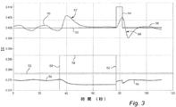
図3は、S2N/CPD実圧力比50、S2N/CPD設定値52、並びにバイパス弁の位置56及び遮断弁の位置54のチャートである。S2N/CPD設定値52は、図2に示すように一定の状態のままではない。それどころか、S2N/CPD圧力比設定値52は、遮断弁が閉鎖されることになると制御装置が判定した場合には上向きステップ状部64として調整される。ステップ状部64は、一時的なものであり、例えば5秒のような数秒間のものとすることができる。ステップ状部64が上昇した後に、S2N/CPD圧力比設定値はその元の値に戻る。
FIG. 3 is a chart of the S2N / CPD
S2N/CPD圧力比設定値に対するステップ状部64の上昇に応答して、制御装置は、S2N/CPD実圧力比を設定値の上昇に対して調整するようにバイパス弁の位置56を急速にかつ大幅に調整する。バイパス弁の位置は、S2N/CPD実圧力比における急速な上昇66を生じさせる急激テップ状部70として調整することができる。バイパス弁に対する急速な調整及びS2N/CPD実圧力比における上昇66は、遮断弁の閉鎖62に応答して発生するS2N/CPD実圧力比の低下68を減少させる傾向がある。具体的には、S2N/CPD設定値がステップ状部64として上昇しかつバイパス弁が設定値のステップ状部64に応答して調整されるので、S2N/CPD実圧力比は、最低レベル53以下に低下することはない。
In response to the stepped
S2N/CPD圧力比設定値に対してステップ状上昇を適用することによって、S2N/CPD実圧力比は、所定の最低レベル以下に低下するか又はそれとは別の所定のレベルになるのが防止される。遮断弁を閉じた時のS2N/CPD圧力比における変化に起因して制御装置が故障状態を宣言する可能性が減少する。さらに、制御装置は、遮断弁を開いた時にS2N/CPD圧力設定値においてステップ状上昇を適用して、そうでなければS2N/CPD実圧力比において発生することになる上向きスパイクの問題を減少させることができる。 By applying a stepped increase to the S2N / CPD pressure ratio setpoint, the actual S2N / CPD pressure ratio is prevented from dropping below a predetermined minimum level or to a predetermined level different from it. The Due to the change in the S2N / CPD pressure ratio when the shut-off valve is closed, the possibility of the controller declaring a fault condition is reduced. In addition, the controller applies a step increase in the S2N / CPD pressure set point when opening the shut-off valve, reducing the problem of upward spikes that would otherwise occur at the S2N / CPD actual pressure ratio. be able to.
現時点で最も実用的かつ好ましい実施形態であると考えられるものに関して本発明を説明してきたが、本発明は開示した実施形態に限定されるものではなく、逆に特許請求の範囲の技術思想及び技術的範囲内に含まれる様々な改良及び均等の構成を保護しようとするものであることを理解されたい。 Although the present invention has been described with respect to what is considered to be the most practical and preferred embodiments at the present time, the invention is not limited to the disclosed embodiments, and conversely, the technical ideas and techniques of the claims It should be understood that various modifications and equivalent arrangements included within the scope are intended to be protected.
10 ガスタービン
12 多段軸流圧縮機
14 駆動シャフト
16 多段軸流タービン
18 出力シャフト
20 燃焼システム
22 出口
24 出口
26 空気導管
28 空気導管
30 弁
32 制御装置
34 エゼクタ
36 導管
37 導管
38 遮断弁
40 バイパス導管
42 バイパス弁
44 圧力及び温度センサ
46 圧力及び温度センサ
48 圧力及び温度センサ
50 S2N/CPD圧力比
52 S2N/CPD圧力比設定値
53 最低レベル
54 位置
56 位置
58 スパイク
60 開状態
62 閉状態
64 ステップ状部
66 上昇
68 低下
DESCRIPTION OF
Claims (10)
前記圧縮機の低圧段から及び該圧縮機の高圧段から加圧空気を抽出する段階(22、24)と、
エゼクタ(34)内において前記高圧段からの抽出された前記加圧空気に対して前記低圧段からの抽出された前記空気を付加し、かつ該エゼクタからの前記加圧空気を前記タービン冷却空気に吐出させる段階と、
前記高圧段からの前記抽出加圧空気のバイパス部分が前記エゼクタをバイパスしかつ該エゼクタから吐出された前記タービン冷却空気に流入するようにする段階(40、42)と、
前記低圧段から前記エゼクタへの前記抽出加圧空気の流れを調整する段階と、
前記低圧段からの前記抽出加圧空気の流れを調整する段階に応答して、前記タービン冷却空気の圧力を含む実圧力比(50)の設定値(52)を変化させる段階(64)と、
前記変化設定値に応答して、前記実圧力比が前記変化設定値に近づくように前記バイパス流を調整する段階(70)と、を含む、
方法。 A method for controlling generation of turbine cooling air by air extracted from a compressor (12) of a gas turbine (10), comprising:
Extracting pressurized air from the low pressure stage of the compressor and from the high pressure stage of the compressor (22, 24);
In the ejector (34), the air extracted from the low pressure stage is added to the compressed air extracted from the high pressure stage, and the pressurized air from the ejector is added to the turbine cooling air. A step of discharging;
Allowing the bypass portion of the extracted pressurized air from the high pressure stage to bypass the ejector and flow into the turbine cooling air discharged from the ejector (40, 42);
Adjusting the flow of the extracted pressurized air from the low pressure stage to the ejector;
Changing a set value (52) of the actual pressure ratio (50) including the pressure of the turbine cooling air in response to adjusting the flow of the extracted pressurized air from the low pressure stage (64);
In response to the change setpoint, adjusting the bypass flow such that the actual pressure ratio approaches the change setpoint (70),
Method.
前記低圧段から前記エゼクタへの前記抽出加圧空気の流れを阻止した後に該低圧段から該エゼクタへの前記抽出加圧空気の流れを調整する段階と、
前記低圧段からの前記抽出加圧空気の流れを調整する段階に応答して、前記タービン冷却空気の圧力を含む実圧力比(50)の設定値(52)を変化させる段階(66、68)と、
前記変化設定値に応答して、付加的バイパス空気流を可能にするように前記バイパス弁を調整し、それによって前記実圧力比が前記変化設定値に近づくようにする段階(56)と、を含む、
方法。 In a system for supplying turbine cooling air by air extracted from a compressor (12) in a gas turbine (10), extracted compressed air (24) from a high compressor stage (high pressure stage) is supplied to a low compressor stage ( Controlling the extracted pressurized air from the high compressor stage to bypass the ejector (34) mixing with the extracted pressurized air (22) from the low pressure stage) and from the bypass extracted pressurized air and the ejector A method of controlling the position of a bypass valve (42) adapted to mix a flow of pressurized air to form turbine cooling air,
Adjusting the flow of the extracted pressurized air from the low pressure stage to the ejector after blocking the flow of the extracted pressurized air from the low pressure stage to the ejector;
In response to adjusting the flow of the extracted pressurized air from the low pressure stage, changing the set value (52) of the actual pressure ratio (50) including the pressure of the turbine cooling air (66, 68) When,
Responsive to the change setpoint, adjusting the bypass valve to allow additional bypass air flow, thereby causing the actual pressure ratio to approach the change setpoint (56); Including,
Method.
9. The method of claim 8, wherein the pressure ratio (50) is due to the pressure ratio of the pressure of the turbine cooling air and the pressure of pressurized air at the compressor discharge to the combustor of the gas turbine.
Applications Claiming Priority (2)
| Application Number | Priority Date | Filing Date | Title |
|---|---|---|---|
| US12/120,621 | 2008-05-14 | ||
| US12/120,621 US8240153B2 (en) | 2008-05-14 | 2008-05-14 | Method and system for controlling a set point for extracting air from a compressor to provide turbine cooling air in a gas turbine |
Publications (3)
| Publication Number | Publication Date |
|---|---|
| JP2009275702A JP2009275702A (en) | 2009-11-26 |
| JP2009275702A5 JP2009275702A5 (en) | 2012-06-07 |
| JP5039085B2 true JP5039085B2 (en) | 2012-10-03 |
Family
ID=40897416
Family Applications (1)
| Application Number | Title | Priority Date | Filing Date |
|---|---|---|---|
| JP2009115096A Expired - Fee Related JP5039085B2 (en) | 2008-05-14 | 2009-05-12 | Method and system for controlling setpoints for extracting air from a compressor and supplying turbine cooling air in a gas turbine |
Country Status (4)
| Country | Link |
|---|---|
| US (1) | US8240153B2 (en) |
| EP (1) | EP2119892A3 (en) |
| JP (1) | JP5039085B2 (en) |
| CN (1) | CN101581252B (en) |
Cited By (1)
| Publication number | Priority date | Publication date | Assignee | Title |
|---|---|---|---|---|
| US11738833B1 (en) | 2020-03-31 | 2023-08-29 | Bombardier Recreational Products Inc. | Fender system for a watercraft |
Families Citing this family (121)
| Publication number | Priority date | Publication date | Assignee | Title |
|---|---|---|---|---|
| US20030097872A1 (en) * | 2001-11-29 | 2003-05-29 | Granitz Charles Robert | System for reducing oil consumption in gas turbine engines |
| WO2009120779A2 (en) | 2008-03-28 | 2009-10-01 | Exxonmobil Upstream Research Company | Low emission power generation and hydrocarbon recovery systems and methods |
| WO2009121008A2 (en) | 2008-03-28 | 2009-10-01 | Exxonmobil Upstream Research Company | Low emission power generation and hydrocarbon recovery systems and methods |
| EP2146057B1 (en) * | 2008-07-16 | 2011-09-07 | Siemens Aktiengesellschaft | Fluidically controlled valve for a gas turbine engine and for a combustor |
| SG195533A1 (en) | 2008-10-14 | 2013-12-30 | Exxonmobil Upstream Res Co | Methods and systems for controlling the products of combustion |
| US8267122B2 (en) * | 2009-06-30 | 2012-09-18 | Ge Aviation Systems Llc | Method and systems for bleed air supply |
| IT1395820B1 (en) * | 2009-09-25 | 2012-10-26 | Nuovo Pignone Spa | COOLING SYSTEM FOR A GAS TURBINE AND ITS FUNCTIONING METHOD |
| US8337139B2 (en) * | 2009-11-10 | 2012-12-25 | General Electric Company | Method and system for reducing the impact on the performance of a turbomachine operating an extraction system |
| MX341477B (en) | 2009-11-12 | 2016-08-22 | Exxonmobil Upstream Res Company * | Low emission power generation and hydrocarbon recovery systems and methods. |
| JP4958967B2 (en) * | 2009-12-15 | 2012-06-20 | 川崎重工業株式会社 | Gas turbine engine with improved ventilation structure |
| US8303695B2 (en) * | 2010-05-17 | 2012-11-06 | General Electric Company | Systems for compressing a gas |
| WO2012003078A1 (en) | 2010-07-02 | 2012-01-05 | Exxonmobil Upstream Research Company | Stoichiometric combustion with exhaust gas recirculation and direct contact cooler |
| SG10201505280WA (en) | 2010-07-02 | 2015-08-28 | Exxonmobil Upstream Res Co | Stoichiometric combustion of enriched air with exhaust gas recirculation |
| MX352291B (en) | 2010-07-02 | 2017-11-16 | Exxonmobil Upstream Res Company Star | Low emission triple-cycle power generation systems and methods. |
| US9732675B2 (en) | 2010-07-02 | 2017-08-15 | Exxonmobil Upstream Research Company | Low emission power generation systems and methods |
| GB201015029D0 (en) | 2010-09-10 | 2010-10-20 | Rolls Royce Plc | Gas turbine engine |
| ITTO20100824A1 (en) * | 2010-10-06 | 2012-04-07 | Ansaldo Energia Spa | CONTROL METHOD TO COOL A TURBINE STAGE IN A GAS TURBINE |
| US20120167587A1 (en) * | 2010-12-30 | 2012-07-05 | Robert Earl Clark | Gas turbine engine with bleed air system |
| TWI564474B (en) | 2011-03-22 | 2017-01-01 | 艾克頌美孚上游研究公司 | Integrated systems for controlling stoichiometric combustion in turbine systems and methods of generating power using the same |
| TWI593872B (en) | 2011-03-22 | 2017-08-01 | 艾克頌美孚上游研究公司 | Integrated system and methods of generating power |
| TWI563166B (en) | 2011-03-22 | 2016-12-21 | Exxonmobil Upstream Res Co | Integrated generation systems and methods for generating power |
| TWI563165B (en) | 2011-03-22 | 2016-12-21 | Exxonmobil Upstream Res Co | Power generation system and method for generating power |
| FR2979136B1 (en) * | 2011-08-16 | 2014-11-14 | Snecma | DEVICE FOR ACTIVATING A PASSIVE EJECTOR VALVE FOR PRESSURIZING AN AIRCRAFT TURBOEER SPEAKER |
| EP2562369B1 (en) | 2011-08-22 | 2015-01-14 | Alstom Technology Ltd | Method for operating a gas turbine plant and gas turbine plant for implementing the method |
| US8973373B2 (en) * | 2011-10-31 | 2015-03-10 | General Electric Company | Active clearance control system and method for gas turbine |
| GB201121426D0 (en) | 2011-12-14 | 2012-01-25 | Rolls Royce Plc | Controller |
| GB201121428D0 (en) | 2011-12-14 | 2012-01-25 | Rolls Royce Plc | Controller |
| US9260974B2 (en) * | 2011-12-16 | 2016-02-16 | General Electric Company | System and method for active clearance control |
| CN104428490B (en) | 2011-12-20 | 2018-06-05 | 埃克森美孚上游研究公司 | The coal bed methane production of raising |
| US9169782B2 (en) * | 2012-01-04 | 2015-10-27 | General Electric Company | Turbine to operate at part-load |
| US9322333B2 (en) * | 2012-01-06 | 2016-04-26 | General Electric Company | System and method for determining a cooling flow parameter downstream from a gas turbine combustor |
| US9376931B2 (en) | 2012-01-27 | 2016-06-28 | General Electric Company | Turbomachine passage cleaning system |
| US20130192251A1 (en) | 2012-01-31 | 2013-08-01 | Peter M. Munsell | Buffer system that communicates buffer supply air to one or more portions of a gas turbine engine |
| US10724431B2 (en) * | 2012-01-31 | 2020-07-28 | Raytheon Technologies Corporation | Buffer system that communicates buffer supply air to one or more portions of a gas turbine engine |
| US9353682B2 (en) | 2012-04-12 | 2016-05-31 | General Electric Company | Methods, systems and apparatus relating to combustion turbine power plants with exhaust gas recirculation |
| US9784185B2 (en) | 2012-04-26 | 2017-10-10 | General Electric Company | System and method for cooling a gas turbine with an exhaust gas provided by the gas turbine |
| US10273880B2 (en) | 2012-04-26 | 2019-04-30 | General Electric Company | System and method of recirculating exhaust gas for use in a plurality of flow paths in a gas turbine engine |
| CA2871581C (en) * | 2012-04-26 | 2017-06-27 | General Electric Company | System and method of recirculating exhaust gas for use in a plurality of flow paths in a gas turbine engine |
| KR101933585B1 (en) * | 2012-07-25 | 2018-12-28 | 한화에어로스페이스 주식회사 | A gas turbine apparatus |
| US9003762B2 (en) * | 2012-10-02 | 2015-04-14 | General Electric Company | Turbine exhaust plume mitigation system |
| US9803865B2 (en) | 2012-12-28 | 2017-10-31 | General Electric Company | System and method for a turbine combustor |
| US10107495B2 (en) | 2012-11-02 | 2018-10-23 | General Electric Company | Gas turbine combustor control system for stoichiometric combustion in the presence of a diluent |
| US9599070B2 (en) | 2012-11-02 | 2017-03-21 | General Electric Company | System and method for oxidant compression in a stoichiometric exhaust gas recirculation gas turbine system |
| US9869279B2 (en) | 2012-11-02 | 2018-01-16 | General Electric Company | System and method for a multi-wall turbine combustor |
| US9574496B2 (en) | 2012-12-28 | 2017-02-21 | General Electric Company | System and method for a turbine combustor |
| US9631815B2 (en) | 2012-12-28 | 2017-04-25 | General Electric Company | System and method for a turbine combustor |
| US10138815B2 (en) | 2012-11-02 | 2018-11-27 | General Electric Company | System and method for diffusion combustion in a stoichiometric exhaust gas recirculation gas turbine system |
| US9708977B2 (en) | 2012-12-28 | 2017-07-18 | General Electric Company | System and method for reheat in gas turbine with exhaust gas recirculation |
| US9611756B2 (en) | 2012-11-02 | 2017-04-04 | General Electric Company | System and method for protecting components in a gas turbine engine with exhaust gas recirculation |
| US10215412B2 (en) | 2012-11-02 | 2019-02-26 | General Electric Company | System and method for load control with diffusion combustion in a stoichiometric exhaust gas recirculation gas turbine system |
| US9175783B2 (en) * | 2012-11-16 | 2015-11-03 | Ford Global Technologies, Llc | Vacuum-actuated wastegate |
| US9562475B2 (en) * | 2012-12-19 | 2017-02-07 | Siemens Aktiengesellschaft | Vane carrier temperature control system in a gas turbine engine |
| US10208677B2 (en) | 2012-12-31 | 2019-02-19 | General Electric Company | Gas turbine load control system |
| US9581081B2 (en) | 2013-01-13 | 2017-02-28 | General Electric Company | System and method for protecting components in a gas turbine engine with exhaust gas recirculation |
| ITMI20130089A1 (en) * | 2013-01-23 | 2014-07-24 | Ansaldo Energia Spa | GAS TURBINE PLANT FOR THE PRODUCTION OF ELECTRICITY AND METHOD TO OPERATE THE PLANT |
| US9512759B2 (en) | 2013-02-06 | 2016-12-06 | General Electric Company | System and method for catalyst heat utilization for gas turbine with exhaust gas recirculation |
| TW201502356A (en) | 2013-02-21 | 2015-01-16 | Exxonmobil Upstream Res Co | Reducing oxygen in a gas turbine exhaust |
| US9938861B2 (en) | 2013-02-21 | 2018-04-10 | Exxonmobil Upstream Research Company | Fuel combusting method |
| WO2014133406A1 (en) | 2013-02-28 | 2014-09-04 | General Electric Company | System and method for a turbine combustor |
| US9784182B2 (en) | 2013-03-08 | 2017-10-10 | Exxonmobil Upstream Research Company | Power generation and methane recovery from methane hydrates |
| US20140250945A1 (en) | 2013-03-08 | 2014-09-11 | Richard A. Huntington | Carbon Dioxide Recovery |
| US9618261B2 (en) | 2013-03-08 | 2017-04-11 | Exxonmobil Upstream Research Company | Power generation and LNG production |
| TW201500635A (en) | 2013-03-08 | 2015-01-01 | Exxonmobil Upstream Res Co | Processing exhaust for use in enhanced oil recovery |
| US9482236B2 (en) | 2013-03-13 | 2016-11-01 | Rolls-Royce Corporation | Modulated cooling flow scheduling for both SFC improvement and stall margin increase |
| US9447702B2 (en) | 2013-06-21 | 2016-09-20 | Sankar K. Mohan | Cooling system and cooling method for use with closed loop systems |
| US9631542B2 (en) | 2013-06-28 | 2017-04-25 | General Electric Company | System and method for exhausting combustion gases from gas turbine engines |
| US9835089B2 (en) | 2013-06-28 | 2017-12-05 | General Electric Company | System and method for a fuel nozzle |
| TWI654368B (en) | 2013-06-28 | 2019-03-21 | 美商艾克頌美孚上游研究公司 | System, method and media for controlling exhaust gas flow in an exhaust gas recirculation gas turbine system |
| US9617914B2 (en) | 2013-06-28 | 2017-04-11 | General Electric Company | Systems and methods for monitoring gas turbine systems having exhaust gas recirculation |
| US10227927B2 (en) | 2013-07-17 | 2019-03-12 | United Technologies Corporation | Supply duct for cooling air from gas turbine compressor |
| US9587510B2 (en) | 2013-07-30 | 2017-03-07 | General Electric Company | System and method for a gas turbine engine sensor |
| US9903588B2 (en) | 2013-07-30 | 2018-02-27 | General Electric Company | System and method for barrier in passage of combustor of gas turbine engine with exhaust gas recirculation |
| US9951658B2 (en) | 2013-07-31 | 2018-04-24 | General Electric Company | System and method for an oxidant heating system |
| EP2857656A1 (en) * | 2013-10-01 | 2015-04-08 | Alstom Technology Ltd | Gas turbine with cooling air cooling system and method for operation of a gas turbine at low part load |
| US10030588B2 (en) | 2013-12-04 | 2018-07-24 | General Electric Company | Gas turbine combustor diagnostic system and method |
| US9752458B2 (en) | 2013-12-04 | 2017-09-05 | General Electric Company | System and method for a gas turbine engine |
| CN103697281A (en) * | 2013-12-27 | 2014-04-02 | 北京华清燃气轮机与煤气化联合循环工程技术有限公司 | Throttle structure between low-pressure bleed gas pipeline and high-pressure bleed gas pipeline of gas turbine |
| US10227920B2 (en) | 2014-01-15 | 2019-03-12 | General Electric Company | Gas turbine oxidant separation system |
| US9915200B2 (en) | 2014-01-21 | 2018-03-13 | General Electric Company | System and method for controlling the combustion process in a gas turbine operating with exhaust gas recirculation |
| US9863267B2 (en) | 2014-01-21 | 2018-01-09 | General Electric Company | System and method of control for a gas turbine engine |
| US10079564B2 (en) | 2014-01-27 | 2018-09-18 | General Electric Company | System and method for a stoichiometric exhaust gas recirculation gas turbine system |
| US9580180B2 (en) | 2014-03-07 | 2017-02-28 | Honeywell International Inc. | Low-pressure bleed air aircraft environmental control system |
| US9644542B2 (en) * | 2014-05-12 | 2017-05-09 | General Electric Company | Turbine cooling system using an enhanced compressor air flow |
| US10047633B2 (en) | 2014-05-16 | 2018-08-14 | General Electric Company | Bearing housing |
| EP3146184B1 (en) * | 2014-05-21 | 2018-03-07 | Siemens Energy, Inc. | Method of providing a cooling flow from a compressor to a turbine in a gas turbine engine |
| EP2957746B1 (en) * | 2014-06-17 | 2021-04-28 | Raytheon Technologies Corporation | High pressure turbine cooling |
| US10060359B2 (en) | 2014-06-30 | 2018-08-28 | General Electric Company | Method and system for combustion control for gas turbine system with exhaust gas recirculation |
| US10655542B2 (en) | 2014-06-30 | 2020-05-19 | General Electric Company | Method and system for startup of gas turbine system drive trains with exhaust gas recirculation |
| US9885290B2 (en) | 2014-06-30 | 2018-02-06 | General Electric Company | Erosion suppression system and method in an exhaust gas recirculation gas turbine system |
| US10767562B2 (en) * | 2014-12-10 | 2020-09-08 | Pratt & Whitney Canada Corp. | Modulated cooled P3 air for impeller |
| US9819292B2 (en) | 2014-12-31 | 2017-11-14 | General Electric Company | Systems and methods to respond to grid overfrequency events for a stoichiometric exhaust recirculation gas turbine |
| US9869247B2 (en) | 2014-12-31 | 2018-01-16 | General Electric Company | Systems and methods of estimating a combustion equivalence ratio in a gas turbine with exhaust gas recirculation |
| US10788212B2 (en) | 2015-01-12 | 2020-09-29 | General Electric Company | System and method for an oxidant passageway in a gas turbine system with exhaust gas recirculation |
| US10094566B2 (en) | 2015-02-04 | 2018-10-09 | General Electric Company | Systems and methods for high volumetric oxidant flow in gas turbine engine with exhaust gas recirculation |
| US10316746B2 (en) | 2015-02-04 | 2019-06-11 | General Electric Company | Turbine system with exhaust gas recirculation, separation and extraction |
| US10253690B2 (en) | 2015-02-04 | 2019-04-09 | General Electric Company | Turbine system with exhaust gas recirculation, separation and extraction |
| US10267270B2 (en) | 2015-02-06 | 2019-04-23 | General Electric Company | Systems and methods for carbon black production with a gas turbine engine having exhaust gas recirculation |
| US10145269B2 (en) | 2015-03-04 | 2018-12-04 | General Electric Company | System and method for cooling discharge flow |
| US10480792B2 (en) | 2015-03-06 | 2019-11-19 | General Electric Company | Fuel staging in a gas turbine engine |
| US20160273401A1 (en) * | 2015-03-19 | 2016-09-22 | General Electric Company | Power generation system having compressor creating excess air flow and eductor for process air demand |
| US9863285B2 (en) | 2015-03-19 | 2018-01-09 | General Electric Company | Power generation system having compressor creating excess gas flow for supplemental gas turbine system |
| US10024197B2 (en) | 2015-03-19 | 2018-07-17 | General Electric Company | Power generation system having compressor creating excess air flow and turbo-expander using same |
| JP5897180B2 (en) * | 2015-04-03 | 2016-03-30 | 三菱日立パワーシステムズ株式会社 | gas turbine |
| US10830148B2 (en) | 2015-04-24 | 2020-11-10 | Raytheon Technologies Corporation | Intercooled cooling air with dual pass heat exchanger |
| US9850819B2 (en) * | 2015-04-24 | 2017-12-26 | United Technologies Corporation | Intercooled cooling air with dual pass heat exchanger |
| KR101790146B1 (en) * | 2015-07-14 | 2017-10-25 | 두산중공업 주식회사 | A gas turbine comprising a cooling system the cooling air supply passage is provided to bypass the outer casing |
| US10502137B2 (en) * | 2015-10-19 | 2019-12-10 | General Electric Company | Gas turbine with a valve cooling system |
| US10480342B2 (en) * | 2016-01-19 | 2019-11-19 | Rolls-Royce Corporation | Gas turbine engine with health monitoring system |
| JP6801968B2 (en) * | 2016-02-15 | 2020-12-16 | 三菱パワー株式会社 | Gas turbine control device and control method, and gas turbine |
| GB2547674A (en) * | 2016-02-25 | 2017-08-30 | Rolls Royce Plc | Gas turbine engine |
| CN105736080B (en) * | 2016-04-29 | 2017-12-05 | 华电郑州机械设计研究院有限公司 | A kind of new thermal power plant's small turbine axle envelope steam bleeding system |
| US20180057171A1 (en) * | 2016-08-23 | 2018-03-01 | Ge Aviation Systems, Llc | Advanced method and aircraft for pre-cooling an environmental control system using a three wheel turbo-machine |
| US10731568B2 (en) | 2016-11-23 | 2020-08-04 | General Electric Company | Systems and methods for reducing airflow imbalances in turbines |
| GB201619960D0 (en) | 2016-11-25 | 2017-01-11 | Rolls Royce Plc | Gas turbine engine |
| US11739697B2 (en) * | 2017-05-22 | 2023-08-29 | Raytheon Technologies Corporation | Bleed flow safety system |
| US10473037B2 (en) | 2017-05-22 | 2019-11-12 | United Technologies Corporation | Passively-driven bleed source switching |
| US11578668B2 (en) | 2017-05-30 | 2023-02-14 | Raytheon Technologies Corporation | Gas turbine engine control based on characteristic of cooled air |
| FR3072414B1 (en) * | 2017-10-16 | 2019-11-01 | Safran Aircraft Engines | DEVICE AND METHOD FOR COOLING A LOW PRESSURE TURBINE IN A TURBOMACHINE |
| DE102018125748A1 (en) * | 2018-10-17 | 2020-04-23 | Rolls-Royce Deutschland Ltd & Co Kg | Failure detection system of a cooling air supply system and failure detection method for a cooling air supply system of a high pressure turbine |
| US11047313B2 (en) | 2018-12-10 | 2021-06-29 | Bell Helicopter Textron Inc. | System and method for selectively modulating the flow of bleed air used for high pressure turbine stage cooling in a power turbine engine |
| US11828223B2 (en) * | 2021-05-28 | 2023-11-28 | Honeywell International Inc. | Variable jet pump |
Family Cites Families (9)
| Publication number | Priority date | Publication date | Assignee | Title |
|---|---|---|---|---|
| IL143765A0 (en) | 1999-01-20 | 2002-04-21 | Mykrolis Corp | Flow controller |
| US6550253B2 (en) * | 2001-09-12 | 2003-04-22 | General Electric Company | Apparatus and methods for controlling flow in turbomachinery |
| US6523346B1 (en) * | 2001-11-02 | 2003-02-25 | Alstom (Switzerland) Ltd | Process for controlling the cooling air mass flow of a gas turbine set |
| GB0224625D0 (en) * | 2002-10-23 | 2002-12-04 | Honeywell Normalair Garrett | Method of balancing the supply of bleed air from a plurality of engines |
| US7536865B2 (en) * | 2005-02-09 | 2009-05-26 | Honeywell International Inc. | Method and system for balancing bleed flows from gas turbine engines |
| US7536864B2 (en) * | 2005-12-07 | 2009-05-26 | General Electric Company | Variable motive nozzle ejector for use with turbine engines |
| US20070137213A1 (en) * | 2005-12-19 | 2007-06-21 | General Electric Company | Turbine wheelspace temperature control |
| US8136361B2 (en) * | 2006-05-04 | 2012-03-20 | General Electric Company | Methods and apparatus for assembling a low noise ejector motive nozzle |
| US7328098B1 (en) * | 2007-04-03 | 2008-02-05 | United Technologies Corporation | Determining bleed valve failures in gas turbine engines |
-
2008
- 2008-05-14 US US12/120,621 patent/US8240153B2/en active Active
-
2009
- 2009-05-08 EP EP09159774.0A patent/EP2119892A3/en not_active Withdrawn
- 2009-05-12 CN CN2009101389251A patent/CN101581252B/en not_active Expired - Fee Related
- 2009-05-12 JP JP2009115096A patent/JP5039085B2/en not_active Expired - Fee Related
Cited By (1)
| Publication number | Priority date | Publication date | Assignee | Title |
|---|---|---|---|---|
| US11738833B1 (en) | 2020-03-31 | 2023-08-29 | Bombardier Recreational Products Inc. | Fender system for a watercraft |
Also Published As
| Publication number | Publication date |
|---|---|
| JP2009275702A (en) | 2009-11-26 |
| US20120117977A1 (en) | 2012-05-17 |
| US8240153B2 (en) | 2012-08-14 |
| CN101581252A (en) | 2009-11-18 |
| CN101581252B (en) | 2013-12-04 |
| EP2119892A2 (en) | 2009-11-18 |
| EP2119892A3 (en) | 2017-11-29 |
Similar Documents
| Publication | Publication Date | Title |
|---|---|---|
| JP5039085B2 (en) | Method and system for controlling setpoints for extracting air from a compressor and supplying turbine cooling air in a gas turbine | |
| US6779346B2 (en) | Control of gas turbine combustion temperature by compressor bleed air | |
| KR101577608B1 (en) | Method and arrangement for gas turbine engine surge control | |
| US20070137213A1 (en) | Turbine wheelspace temperature control | |
| KR20010076202A (en) | System and method for pressure modulation of turbine sidewall cavities | |
| JP3854556B2 (en) | Gas turbine plant control mechanism | |
| JP2009103125A (en) | System for delivering air from multi-stage compressor to turbine portion of gas turbine engine | |
| US8578717B2 (en) | Method for controlling the load variations in a gas turbine | |
| US10358947B2 (en) | Combined cycle gas turbine plant | |
| US10858996B2 (en) | Gas turbine startup method and device | |
| JP4163131B2 (en) | Two-shaft gas turbine power generation system and its stopping method | |
| JP2014181700A (en) | Compressor start bleed system for turbine system, and method of controlling compressor start bleed system | |
| EP2746555B1 (en) | Fuel routing system of a gas turbine engine and method of routing fuel | |
| JP3212895B2 (en) | Gas turbine fuel supply device and control device therefor | |
| JP2013057278A (en) | Gas turbine | |
| US11459961B2 (en) | Method for operating a power plant, and power plant | |
| JP5897180B2 (en) | gas turbine | |
| US10167742B2 (en) | Steam cycle, and method for operating a steam cycle | |
| JP2017180454A (en) | Variable flow compressor of gas turbine | |
| JP4473464B2 (en) | Operation method of combined cycle power plant | |
| JP2020186667A (en) | Fuel gas supply device and method |
Legal Events
| Date | Code | Title | Description |
|---|---|---|---|
| A521 | Request for written amendment filed |
Free format text: JAPANESE INTERMEDIATE CODE: A523 Effective date: 20120413 |
|
| A621 | Written request for application examination |
Free format text: JAPANESE INTERMEDIATE CODE: A621 Effective date: 20120413 |
|
| A871 | Explanation of circumstances concerning accelerated examination |
Free format text: JAPANESE INTERMEDIATE CODE: A871 Effective date: 20120413 |
|
| A975 | Report on accelerated examination |
Free format text: JAPANESE INTERMEDIATE CODE: A971005 Effective date: 20120511 |
|
| TRDD | Decision of grant or rejection written | ||
| A01 | Written decision to grant a patent or to grant a registration (utility model) |
Free format text: JAPANESE INTERMEDIATE CODE: A01 Effective date: 20120612 |
|
| A01 | Written decision to grant a patent or to grant a registration (utility model) |
Free format text: JAPANESE INTERMEDIATE CODE: A01 |
|
| A61 | First payment of annual fees (during grant procedure) |
Free format text: JAPANESE INTERMEDIATE CODE: A61 Effective date: 20120706 |
|
| FPAY | Renewal fee payment (event date is renewal date of database) |
Free format text: PAYMENT UNTIL: 20150713 Year of fee payment: 3 |
|
| R150 | Certificate of patent or registration of utility model |
Ref document number: 5039085 Country of ref document: JP Free format text: JAPANESE INTERMEDIATE CODE: R150 Free format text: JAPANESE INTERMEDIATE CODE: R150 |
|
| R250 | Receipt of annual fees |
Free format text: JAPANESE INTERMEDIATE CODE: R250 |
|
| R250 | Receipt of annual fees |
Free format text: JAPANESE INTERMEDIATE CODE: R250 |
|
| R250 | Receipt of annual fees |
Free format text: JAPANESE INTERMEDIATE CODE: R250 |
|
| R250 | Receipt of annual fees |
Free format text: JAPANESE INTERMEDIATE CODE: R250 |
|
| R250 | Receipt of annual fees |
Free format text: JAPANESE INTERMEDIATE CODE: R250 |
|
| R250 | Receipt of annual fees |
Free format text: JAPANESE INTERMEDIATE CODE: R250 |
|
| R250 | Receipt of annual fees |
Free format text: JAPANESE INTERMEDIATE CODE: R250 |
|
| LAPS | Cancellation because of no payment of annual fees |