JP5014427B2 - Thermoelectric power generation system using segmented thermoelectric elements - Google Patents
Thermoelectric power generation system using segmented thermoelectric elements Download PDFInfo
- Publication number
- JP5014427B2 JP5014427B2 JP2009521845A JP2009521845A JP5014427B2 JP 5014427 B2 JP5014427 B2 JP 5014427B2 JP 2009521845 A JP2009521845 A JP 2009521845A JP 2009521845 A JP2009521845 A JP 2009521845A JP 5014427 B2 JP5014427 B2 JP 5014427B2
- Authority
- JP
- Japan
- Prior art keywords
- thermoelectric
- segment
- elements
- heat transfer
- segments
- Prior art date
- Legal status (The legal status is an assumption and is not a legal conclusion. Google has not performed a legal analysis and makes no representation as to the accuracy of the status listed.)
- Expired - Fee Related
Links
Images


Classifications
-
- H—ELECTRICITY
- H10—SEMICONDUCTOR DEVICES; ELECTRIC SOLID-STATE DEVICES NOT OTHERWISE PROVIDED FOR
- H10N—ELECTRIC SOLID-STATE DEVICES NOT OTHERWISE PROVIDED FOR
- H10N10/00—Thermoelectric devices comprising a junction of dissimilar materials, i.e. devices exhibiting Seebeck or Peltier effects
- H10N10/80—Constructional details
- H10N10/85—Thermoelectric active materials
- H10N10/857—Thermoelectric active materials comprising compositions changing continuously or discontinuously inside the material
-
- H—ELECTRICITY
- H10—SEMICONDUCTOR DEVICES; ELECTRIC SOLID-STATE DEVICES NOT OTHERWISE PROVIDED FOR
- H10N—ELECTRIC SOLID-STATE DEVICES NOT OTHERWISE PROVIDED FOR
- H10N10/00—Thermoelectric devices comprising a junction of dissimilar materials, i.e. devices exhibiting Seebeck or Peltier effects
- H10N10/10—Thermoelectric devices comprising a junction of dissimilar materials, i.e. devices exhibiting Seebeck or Peltier effects operating with only the Peltier or Seebeck effects
- H10N10/13—Thermoelectric devices comprising a junction of dissimilar materials, i.e. devices exhibiting Seebeck or Peltier effects operating with only the Peltier or Seebeck effects characterised by the heat-exchanging means at the junction
-
- H—ELECTRICITY
- H10—SEMICONDUCTOR DEVICES; ELECTRIC SOLID-STATE DEVICES NOT OTHERWISE PROVIDED FOR
- H10N—ELECTRIC SOLID-STATE DEVICES NOT OTHERWISE PROVIDED FOR
- H10N10/00—Thermoelectric devices comprising a junction of dissimilar materials, i.e. devices exhibiting Seebeck or Peltier effects
- H10N10/10—Thermoelectric devices comprising a junction of dissimilar materials, i.e. devices exhibiting Seebeck or Peltier effects operating with only the Peltier or Seebeck effects
- H10N10/17—Thermoelectric devices comprising a junction of dissimilar materials, i.e. devices exhibiting Seebeck or Peltier effects operating with only the Peltier or Seebeck effects characterised by the structure or configuration of the cell or thermocouple forming the device
Description
本出願は、2005年5月24日出願の米国特許出願11/136,334号の部分継続出願であり、参照としてその全体が本明細書に取り込まれ、2003年8月18日出願の米国特許第6,959,555号の継続出願であり、参照としてその全体が本明細書に取り込まれ、2002年8月23日出願の米国特許第7,231,772号の部分継続出願であり、参照としてその全体が本明細書に取り込まれ、2003年3月31日出願の米国特許第7,111,465号の部分継続出願であり、参照としてその全体が本明細書に取り込まれ、2001年4月27日出願の米国特許第6,539,725号の継続出願であり、参照としてその全体が本明細書に取り込まれ、2001年2月9日出願の米国特許仮出願第60/267,657号に関連し、利益を主張し、参照としてその全体が本明細書に取り込まれる。さらに、本出願は、2006年7月28日付の米国特許仮出願第60/834,006号の利益を主張し、参照としてその全体が本明細書に取り込まれる。 This application is a continuation-in-part of US Patent Application No. 11 / 136,334, filed May 24, 2005, which is hereby incorporated by reference in its entirety and is a US patent filed on August 18, 2003. No. 6,959,555, which is a continuation application, which is incorporated herein by reference in its entirety and is a partial continuation application of US Pat. No. 7,231,772 filed on August 23, 2002, with reference Which is incorporated herein in its entirety and is a continuation-in-part of US Pat. No. 7,111,465 filed on Mar. 31, 2003, which is incorporated herein by reference in its entirety. No. 6,539,725, filed on May 27, which is incorporated herein by reference in its entirety, and US Provisional Patent Application No. 60 / 267,657, filed February 9, 2001. Related to, and claims the benefit its entirety by reference is incorporated herein. In addition, this application claims the benefit of US Provisional Application No. 60 / 834,006, dated July 28, 2006, which is hereby incorporated by reference in its entirety.
発明の分野
本明細書の開示は、半導体冷却/加熱/発電システムのための優れた構成に関する。
関連技術の説明
熱電装置(TE)は、特定の材料の特性を利用して、電流の存在下で材料にわたって温度勾配を生じさせる。通常の熱電装置は、装置内の熱電材料として、P型およびN型の半導体を用いる。これらが、所望の加熱または冷却機能が得られるような方法で、物理的かつ電気的に構成される。
FIELD OF THE DISCLOSURE The disclosure herein relates to an excellent configuration for a semiconductor cooling / heating / power generation system.
Description of Related Art A thermoelectric device (TE) utilizes the properties of a particular material to create a temperature gradient across the material in the presence of an electric current. A typical thermoelectric device uses P-type and N-type semiconductors as thermoelectric materials in the device. These are physically and electrically constructed in such a way that the desired heating or cooling function is obtained.
今日において熱電装置に使用されている最も一般的な構成が、図1Aに示されている。一般に、P型およびN型の熱電素子102が、2つの基板104の間の矩形のアセンブリ100に配列される。電流Iが、両方の型の素子を通って流れる。素子は、素子102の端部へと配置された銅製のシャント106によって直列に接続されている。DC電圧108が印加されると、TE素子にわたって温度勾配が生じる。TEは、一般に、液体、気体、および固体の物体を冷却するために使用される。
The most common configuration used in thermoelectric devices today is shown in FIG. 1A. In general, P-type and N-type
半導体冷却/加熱/発電(SSCHP)システムが、軍事および航空宇宙の機器、温度制御、ならびに発電の用途において、1960年代から使用されてきている。そのようなシステムは、それらが果たす機能に対して高価に過ぎ、かつ出力密度が低いため、商業的な使用は限定的であり、SSCHPシステムは、商業的に受け入れるためには大きすぎ、コストが高すぎ、効率が低すぎ、かつ重すぎであった。 Semiconductor cooling / heating / power generation (SSCHP) systems have been used since the 1960s in military and aerospace equipment, temperature control, and power generation applications. Such systems are too expensive for the functions they perform and have low power density, so commercial use is limited, and SSCHP systems are too large and costly to accept commercially. Too high, efficiency too low and too heavy.
近年の材料の改善により、効率および出力密度は、現在のシステムの最大100倍まで高められる見込みである。しかしながら、熱電(TE)装置の利用は、低い効率、低い出力密度、および高いコストによって制限されている。 Recent material improvements are expected to increase efficiency and power density up to 100 times that of current systems. However, the use of thermoelectric (TE) devices is limited by low efficiency, low power density, and high cost.
今日のTE材料において、ZT=0.9のモジュールによって生み出されるピーク効率での冷却力が、最大冷却力の約22%であることが、TE設計ガイド(Melcor Corporationの「Thermoelectric Handbook」、1995年、16−17頁)から周知である。すなわち、可能な最高の効率を達成するためには、最大冷却での動作において必要とされる数に比べ、いくつかのTEモジュールが必要である。結果として、効率的な動作のためのTEモジュールのコストが、大幅に高くなり、結果としてのシステムが、著しく大きくなる。 In today's TE materials, the TE design guide (Mercor Corporation's “Thermoelectric Handbook”, 1995) shows that the cooling power at peak efficiency produced by a module with ZT = 0.9 is about 22% of the maximum cooling power. 16-17). That is, to achieve the highest possible efficiency, several TE modules are required compared to the number required in operation with maximum cooling. As a result, the cost of the TE module for efficient operation is significantly increased and the resulting system is significantly larger.
文献(例えば、Goldsmid, H.J.の「Electronic Refrigeration」、1986年、9頁を参照)から、最大の熱冷却率を
From the literature (see, for example, Goldsmid, HJ, “Electronic Refrigeration”, 1986,
![]()
![]()
と記述できることが知られており、ここで
qCOPTは、最適冷却熱出力であり、
IOPTは、最適電流であり、
αは、ゼーベック係数であり、
Rは、システムの電気抵抗であり、
Kは、システムの熱伝導であり、
ΔTは、高温側温度と低温側温度との間の差であり、
TCは、低温側温度である。
Where q COPT is the optimal cooling heat output,
I OPT is the optimum current,
α is the Seebeck coefficient,
R is the electrical resistance of the system,
K is the heat conduction of the system,
ΔT is the difference between the high temperature side temperature and the low temperature side temperature,
T C is the cold side temperature.
さらに、Goldsmidから、 In addition, from Goldsmid

であり、ここで
Zは、材料の熱電性能指数であり、
TAVEは、高温側温度および低温側温度の平均であり、
Where Z is the thermoelectric figure of merit of the material,
T AVE is the average of the high temperature side temperature and the low temperature side temperature,
![]()
![]()
である。 It is.
式(2)を(1)に代入すると、 Substituting equation (2) into (1),
である。 It is.
式(3)の右辺の括弧内の項は、TEシステムのサイズ(または寸法)と無関係であり、したがって冷却の量qOPTは、材料の特性およびKのみの関数である。図1の構成について、Kを The term in parentheses on the right side of equation (3) is independent of the size (or dimension) of the TE system, so the amount of cooling q OPT is a function of the material properties and K only. For the configuration of FIG.
と記述することができ、ここで、λは、NおよびPの材料の平均の熱伝導率であり、ACは、素子の面積であり、Lは、各素子の長さである。 And can be described, wherein, lambda is the average thermal conductivity of the N and P of the material, A C is the area of the element, L is the length of each element.
αが、材料の固有の特性であるため、比LC/ACが一定である限りにおいて、最適熱出力qOPTは同じである。IOPTに等しい電流において、抵抗は Since α is an intrinsic property of the material, the optimal thermal output q OPT is the same as long as the ratio L C / AC is constant. At a current equal to I OPT , the resistance is
であり、ここで、ρTEは、TE素子の固有の平均抵抗率であり、ROCは、TE材料の抵抗であり、RPCは、寄生抵抗である。 Where ρ TE is the intrinsic average resistivity of the TE element, R OC is the resistance of the TE material, and R PC is the parasitic resistance.
とりあえず、RPがゼロであると仮定すると、Rは一定である。LC/ACが固定されている場合、IOPTは一定である。比LC/ACが変化する場合のみ、K、したがってqCOPTが変化し、ROC、したがってIOPTが変化する。 For the time being, assuming that R P is zero, R is constant. When L C / A C is fixed, I OPT is constant. Only when the ratio L C / A C changes, K and therefore q COPT change, and R OC and thus I OPT change.
通常は、同じ冷却出力において、装置をより小さくすることが好都合である。熱電システムにおける重要な制約は、例えば固定のACに対して長さLCが小さくされるとき、TE材料の損失に対する寄生抵抗の損失の比φCが、比較的大きくなる点にある。 Usually it is convenient to make the device smaller at the same cooling power. Important limitation in the thermoelectric system, for example, when the length L C is small relative to a fixed A C, the ratio phi C loss of parasitic resistance to loss of the TE material lies in that relatively large.
これを、典型的なTE対を示した図1Cを参照することによって、理解することができる。いくつかの寄生損失が生じるが、上手く設計されたTEにおける最大の寄生損失は、シャント106からの寄生損失である。TE素子102ごとのシャント106の抵抗は、おおよそ
This can be understood by referring to FIG. 1C which shows a typical TE pair. Although some parasitic losses occur, the largest parasitic loss in a well-designed TE is the parasitic loss from the
であり、ここで、GCは、TE素子間のすき間であり、BCは、TE素子およびシャントの広がりであり、WCは、TE素子およびシャントの幅であり、TCは、シャントの厚さであり、PSCは、シャントの抵抗率である。 , And the where, G C is the gap between the TE elements, B C is the TE elements and shunts spread, W C is the TE element and the shunt width, T C is the shunt is the thickness, P SC is the resistivity of the shunt.
図1の構成において、TE素子の抵抗は、 In the configuration of FIG. 1, the resistance of the TE element is
であり、ここで、LCは、TE素子の長さである。 Where L C is the length of the TE element.
したがって、式(7)および(8)を(6)に使用して、 Therefore, using equations (7) and (8) for (6),
である。 It is.
特定の実施形態において、熱電システムが提供される。この熱電システムは、互いに電気的に連絡した第1の複数のセグメントを備える第1の熱電素子を備える。さらに熱電システムは、互いに電気的に連絡した第2の複数のセグメントを備える第2の熱電素子を備える。さらに熱電システムは、少なくとも第1の部位および第2の部位を備える熱伝達装置を備える。第1の部位が、第1の熱電素子と第2の熱電素子との間に挟まれている。第2の部位が、第1の部位から離れるように突き出しており、作動媒体に熱的に連絡するように構成されている。 In certain embodiments, a thermoelectric system is provided. The thermoelectric system includes a first thermoelectric element that includes a first plurality of segments in electrical communication with each other. The thermoelectric system further includes a second thermoelectric element comprising a second plurality of segments in electrical communication with each other. The thermoelectric system further includes a heat transfer device including at least a first part and a second part. The first part is sandwiched between the first thermoelectric element and the second thermoelectric element. The second part protrudes away from the first part and is configured to be in thermal communication with the working medium.
特定の実施形態においては、熱電システムが提供される。この熱電システムは、複数の熱電素子を備えており、熱電素子のうちの少なくともいくつかが複数のセグメントを備える。さらに熱電システムは、複数の熱伝達装置を備えており、熱伝達装置の少なくともいくつかが、少なくとも第1の部位および第2の部位を備える。第1の部位が、熱電素子および熱伝達装置からなる少なくとも1つのスタックを形成すべく、複数の熱電素子のうちの少なくとも2つの熱電素子の間に挟まれている。第2の部位が、スタックから離れるように突き出しており、作動媒体に熱的に連絡するように構成されている。 In certain embodiments, a thermoelectric system is provided. The thermoelectric system includes a plurality of thermoelectric elements, and at least some of the thermoelectric elements include a plurality of segments. The thermoelectric system further includes a plurality of heat transfer devices, and at least some of the heat transfer devices include at least a first portion and a second portion. A first portion is sandwiched between at least two thermoelectric elements of the plurality of thermoelectric elements to form at least one stack of thermoelectric elements and heat transfer devices. A second portion projects away from the stack and is configured to be in thermal communication with the working medium.
特定の実施形態においては、熱電システムの製造方法が提供される。この方法は、複数の熱電素子を用意する工程を含んでおり、これらの熱電素子の少なくともいくつかは、複数のセグメントを備える。この方法は、複数の熱伝達装置を用意する工程をさらに含んでおり、これらの熱伝達装置の少なくともいくつかは、少なくとも第1の部位および第2の部位を備える。この方法は、複数の熱電素子および複数の熱伝達装置を、交互の熱電素子および熱伝達装置からなる少なくとも1つのスタックを形成するように組み立てる工程をさらに含む。熱伝達装置の第1の部位が、少なくとも2つの隣接する熱電素子の間に挟まれる。熱伝達装置の第2の部位が、スタックから離れるように突き出し、作動媒体に熱的に連絡するように構成される。 In certain embodiments, a method for manufacturing a thermoelectric system is provided. The method includes providing a plurality of thermoelectric elements, at least some of these thermoelectric elements comprising a plurality of segments. The method further includes providing a plurality of heat transfer devices, at least some of these heat transfer devices comprising at least a first portion and a second portion. The method further includes assembling the plurality of thermoelectric elements and the plurality of heat transfer devices to form at least one stack of alternating thermoelectric elements and heat transfer devices. A first portion of the heat transfer device is sandwiched between at least two adjacent thermoelectric elements. A second portion of the heat transfer device is configured to protrude away from the stack and to be in thermal communication with the working medium.
本明細書の開示のこれらの態様および他の態様が、図面および以下のさらに詳細な説明から明らかになるであろう。 These and other aspects of the disclosure herein will become apparent from the drawings and the more detailed description that follows.
本明細書の文脈において、用語「熱電モジュール」および「TEモジュール」は、(1)従来からの熱電モジュール(California州San DiegoのHi Z Technologies, Inc.によって製造されているものなど)、(2)量子トンネルコンバータ、(3)熱イオン・モジュール、(4)磁気熱量モジュール、(5)熱電、磁気熱量、量子、トンネリング、および熱イオンの各効果のうちの1つまたは任意の組み合わせを利用する素子、(6)上記(1)〜(6)の任意の組み合わせ、アレイ、アセンブリ、および他の構造、というこれらの用語の通常かつ慣れ親しまれた意味からなる広い感覚で使用される。用語「熱電素子」は、より具体的に、熱電、熱イオン、量子、トンネリング、およびこれらの効果の任意の組み合わせを使用して動作する個々の素子を指す。 In the context of this specification, the terms “thermoelectric module” and “TE module” are (1) conventional thermoelectric modules (such as those manufactured by Hi Z Technologies, Inc., San Diego, Calif.), (2 Utilizing one or any combination of:) quantum tunnel converter, (3) thermionic module, (4) magnetocaloric module, (5) thermoelectric, magnetocaloric, quantum, tunneling, and thermionic effects It is used in a broad sense consisting of the usual and familiar meanings of these terms: element, (6) any combination of (1)-(6) above, arrays, assemblies, and other structures. The term “thermoelectric element” more specifically refers to an individual element that operates using thermoelectric, thermionic, quantum, tunneling, and any combination of these effects.
以下の説明では、熱電またはSSCHPシステムを例として説明する。しかしながら、そのような技術および説明は、すべてのSSCHPシステムを包含する。 In the following description, a thermoelectric or SSCHP system will be described as an example. However, such techniques and descriptions encompass all SSCHP systems.
したがって、本発明は、説明および例示の目的のために、特定の実施形態における実施例を使用して紹介される。以下に記載されるさまざまな実施例が、さまざまな構成を説明し、所望の改善を達成するために使用可能である。本明細書によれば、特定の実施形態および実施例は、あくまでも例示であって、提示される本発明を限定しようとするものではない。さらに、冷却側、加熱側、低温側、高温側、より温度の低い側、およびより温度の高い側、などといった用語が、いかなる特定の温度も指示しておらず、相対的な用語であることを理解すべきである。例えば、熱電素子またはアレイあるいはモジュールの「高温」側が室温であって、「低温」側が室温よりも低い温度であってよい。この反対も、真実であってよい。すなわち、これらの用語は、互いに相対的であって、熱電の片側が、反対の指定の温度の側よりも高い温度または低い温度であることを示している。 Accordingly, the present invention is introduced using examples in specific embodiments for purposes of explanation and illustration. Various embodiments described below can be used to describe various configurations and achieve the desired improvements. According to this specification, specific embodiments and examples are illustrative only and are not intended to limit the present invention presented. In addition, terms such as cooling side, heating side, low temperature side, high temperature side, lower temperature side, and higher temperature side do not indicate any specific temperature and are relative terms. Should be understood. For example, the “hot” side of a thermoelectric element or array or module may be at room temperature and the “cold” side may be a temperature below room temperature. The opposite may also be true. That is, these terms are relative to each other, indicating that one side of the thermoelectric is a higher or lower temperature than the opposite specified temperature side.
Improved Efficiency Thermoelectics Utilizing Thermal Isolationという名称の米国特許第6,539,735号に記載の形状のための効率向上が、多数の重要な用途について、追加の50%〜100%の改善をもたらす。なされる材料の改善との組み合わせにおいて、係数4以上のシステムの効率向上が、近い将来において可能であると思われる。このような大きな改善の予想は、新規な用途のためのSSCHPシステムを開発するための技術および努力への新規な関心につながっている。 The increased efficiency for the shape described in US Pat. No. 6,539,735, entitled Improved Thermoelectrics Utilityizing Thermal Isolation, provides an additional 50% to 100% improvement for a number of important applications. In combination with the material improvements that are made, it seems possible to increase the efficiency of systems with a factor of 4 or more in the near future. Such significant improvement expectations have led to new interest in technology and efforts to develop SSCHHP systems for new applications.
広くには、本明細書の開示は、新規な一群のSSCHP構成を説明する。これらの構成は、コンパクトで高効率なエネルギー変換を実現し、比較的低コストであることができる。一般に、TE素子またはモジュール(本文においては、まとめて素子と呼ぶ)が熱交換器の間に挟まれている特定の実施形態が開示される。TE素子は、好都合には、熱交換器を挟んでいる任意の2つの素子について、同じ温度の種類の側が熱交換器に面するように向けられる。例えば、熱交換器を挟んでいるTE素子の各々の低温側が、同じ熱交換器またはシャントに面し、したがってお互いに面する。或る一群の構成においては、少なくとも1つの作動媒体が、もたらされる冷却または加熱が作動媒体にとって付加的であるように、少なくとも2つの熱交換器を順に通過する。この構成は、上記の参考文献に記載のとおり高いシステム効率および出力密度を呈する製造可能なシステムにおいて、米国特許第6,539,725号に記載されているように、熱絶縁の利点を利用するという追加の利益を有している。この特許に説明されているとおり、一般に、TE装置においては、TE素子からなるアセンブリの全体を熱的に絶縁されたサブアセンブリまたはセクションへと分割することによって、効率の向上または改善が達成される。例えば、熱交換器を、作動媒体の流れの方向において熱絶縁をもたらすように分割することができる。例えば、TEシステムが、冷却側および加熱側を有するTEアレイを形成する複数のTE素子を有しており、これら複数のTE素子が、アレイを横切る少なくとも1つの方向においてお互いから実質的に絶縁される。好ましくは、熱絶縁は、作動媒体の流れの方向である。この熱絶縁を、熱交換器が作動媒体の流れの方向において熱的に絶縁された部位を有するように、セクションにて構成された熱交換器を有することによってもたらすことができる。 Broadly, the disclosure herein describes a novel group of SSCHHP configurations. These configurations can achieve compact and highly efficient energy conversion and can be relatively low cost. In general, specific embodiments are disclosed in which TE elements or modules (collectively referred to herein as elements) are sandwiched between heat exchangers. The TE element is conveniently oriented so that the same temperature type side faces the heat exchanger for any two elements sandwiching the heat exchanger. For example, the cold side of each TE element sandwiching the heat exchanger faces the same heat exchanger or shunt and thus faces each other. In one group of configurations, at least one working medium passes in sequence through at least two heat exchangers so that the cooling or heating provided is additive to the working medium. This configuration takes advantage of thermal isolation, as described in US Pat. No. 6,539,725, in manufacturable systems that exhibit high system efficiency and power density as described in the above references. Has the additional benefit of As described in this patent, in general, in TE devices, increased or improved efficiency is achieved by dividing the entire assembly of TE elements into thermally isolated subassemblies or sections. . For example, the heat exchanger can be divided to provide thermal insulation in the direction of working medium flow. For example, a TE system has a plurality of TE elements that form a TE array having a cooling side and a heating side, the plurality of TE elements being substantially isolated from each other in at least one direction across the array. The Preferably, the thermal insulation is in the direction of working medium flow. This thermal insulation can be provided by having a heat exchanger configured in sections such that the heat exchanger has a thermally insulated portion in the direction of working medium flow.
本明細書の開示において、作動流体について同じ温度の種類の熱交換器を順に使用することが、それ自身で一種の熱絶縁をもたらす。さらに、熱交換器またはTE素子、あるいはTEモジュールまたは任意の組み合わせを、少なくとも1つの作動流体が順に通過する一連または順次の熱交換器を有することによってもたらされる熱絶縁の上または上方に、作動流体の流れの方向の熱絶縁をもたらすように構成することができる。 In the present disclosure, the sequential use of the same temperature type heat exchanger for the working fluid itself provides a kind of thermal insulation. In addition, the working fluid above or above the thermal insulation provided by having a series or sequential heat exchanger through which at least one working fluid is passed in sequence through a heat exchanger or TE element, or TE module or any combination. Can be configured to provide thermal insulation in the direction of flow.
冷却および/または加熱の用途について開示される原理は、発電の用途にも同様に適用可能であり、発電のためのアセンブリを生成するために任意の方法で組み合わせることができるあらゆる構成、設計の詳細、および類似の部位も、やはり適用可能である。システムを、所与の用途について効率を最大にするような方法で調整することができるが、全体的な原理は生かされる。 The principles disclosed for cooling and / or heating applications are equally applicable to power generation applications, and any configuration, design details that can be combined in any way to produce an assembly for power generation , And similar sites are also applicable. The system can be tuned in such a way as to maximize efficiency for a given application, but the overall principle is utilized.
本出願において説明される実施形態は、SSCHP装置の構成の複雑さおよびコストを低くしつつ、依然として熱絶縁からの効率向上を維持または改善する。 The embodiments described in this application still maintain or improve the efficiency gain from thermal isolation while reducing the complexity and cost of SSCHHP device configuration.
さらに、使用されるTE材料を少なくすること、およびピーク効率のより近くでの動作を促進することによって、コストを低減するための特定の実施形態も開示される。多数の実施形態が、寄生損失の大幅な低減を達成する(例えば、図12〜31を参照)。 Furthermore, certain embodiments for reducing costs by reducing the TE material used and facilitating operation closer to peak efficiency are also disclosed. A number of embodiments achieve a significant reduction in parasitic losses (see, eg, FIGS. 12-31).
本明細書に開示される実施形態の一態様は、複数のN型の熱電素子および複数のP型の熱電素子を有する熱電システムを含む。好ましくは、複数の第1のシャントおよび複数の第2のシャントが設けられる。第1のシャントの少なくともいくつかが、少なくとも1つのN型の熱電素子と少なくとも1つのP型の熱電素子との間に挟まれ、第2のシャントの少なくともいくつかが、少なくとも1つのP型の熱電素子と少なくとも1つのN型の熱電素子との間に挟まれ、第1および第2のシャントを交互に備える熱電素子のスタックが形成され、第1のシャントの少なくともいくつかおよび第2のシャントの少なくともいくつかが、スタックから離れるように異なる方向に突き出す。 One aspect of the embodiments disclosed herein includes a thermoelectric system having a plurality of N-type thermoelectric elements and a plurality of P-type thermoelectric elements. Preferably, a plurality of first shunts and a plurality of second shunts are provided. At least some of the first shunts are sandwiched between at least one N-type thermoelectric element and at least one P-type thermoelectric element, and at least some of the second shunts are at least one P-type thermoelectric element. A stack of thermoelectric elements sandwiched between the thermoelectric element and at least one N-type thermoelectric element and comprising alternating first and second shunts is formed, wherein at least some of the first shunts and the second shunt At least some of them protrude in different directions away from the stack.
好ましくは、熱電素子は、5ミクロン〜1.2mm、超格子およびヘテロ構造の熱電設計については20ミクロン〜200ミクロン、他の実施形態においては100〜600ミクロンなど、きわめて薄く構成される。これらの設計は、熱電材料の使用の大幅な削減をもたらす。 Preferably, the thermoelectric elements are constructed very thin, such as 5 microns to 1.2 mm, 20 microns to 200 microns for superlattice and heterostructure thermoelectric designs, and 100 to 600 microns in other embodiments. These designs result in a significant reduction in the use of thermoelectric materials.
一つの実施形態においては、熱電システムが、スタックへと電気的に接続された電流源をさらに備えており、駆動電流が、直列の熱伝達装置および熱電素子を横切って通過する。他の実施形態においては、熱伝達装置が、P型の熱電素子の少なくともいくつかをN型の熱電素子の少なくともいくつかから熱的に絶縁している。 In one embodiment, the thermoelectric system further comprises a current source electrically connected to the stack, and the drive current passes across the series heat transfer devices and thermoelectric elements. In other embodiments, the heat transfer device thermally insulates at least some of the P-type thermoelectric elements from at least some of the N-type thermoelectric elements.
一つの実施形態においては、熱伝達装置が、熱伝達装置を所定の方向に通過して流れるように作動流体を受け取る。好ましくは、熱伝達装置が熱交換器であり、1つ以上の熱交換器要素を内側に備えるハウジングを有することができる。 In one embodiment, the heat transfer device receives the working fluid to flow past the heat transfer device in a predetermined direction. Preferably, the heat transfer device is a heat exchanger and can have a housing with one or more heat exchanger elements inside.
別の実施形態においては、第1のシャントの少なくともいくつかが、第2のシャント部分から電気的に絶縁されているが第2のシャント部分へと熱的に接続されている第1の電極部分で構成されている。 In another embodiment, a first electrode portion in which at least some of the first shunts are electrically isolated from the second shunt portion but are thermally connected to the second shunt portion. It consists of
図2が、熱電アレイ200のための好都合な配置構成の第1の一般的な実施形態を示している。アレイ200が、複数のTEモジュール201、211、212、213、218を、複数の第1の側の熱交換器202、203、205および複数の第2の側の熱交換器206、207、209との良好な熱的連絡にて有している。第1の側の熱交換器および第2の側の熱交換器という呼称は、それらの熱交換器が全SSCHPシステムの一方の側または他方の側にあることを含意も示唆もしておらず、単に、熱交換器が熱電モジュールの低温側または高温側のいずれかに熱的に連絡していることを含意および示唆している。これは、熱交換器が実際に熱電モジュールの間に挟まれているという点で、図から明らかである。その意味で、熱交換器は、熱電モジュールの第1の側または第2の側に熱的に連絡している。第1のTEモジュール201の低温側が、第1の側の熱交換器205に熱的に接しており、TEモジュール201の高温側が、入り口の第2の側の熱交換器206に熱的に接している。流体などの第2の作動媒体215が、図2の右上の角において、入り口の第2の側の熱交換器206を通ってアレイ200に進入し、左下の付近において、最終または出口の第2の側の熱交換器209から出る。第1の作動媒体216が、左上において、入り口の第1の側の熱交換器202を通って進入し、右下の付近において、最終または出口の第1の側の熱交換器205から出る。電源(図示されていない)へと接続された電気ワイヤ210(他のTEモジュールについても同様)が、それぞれのTEモジュール201へとつながっている。図示のとおり種々の熱交換器202、203、205、206、207、および209を順に通過して、第1の導管208(図2においては線として表現されている)が、第2の作動媒体215を運び、第2の導管204が、第1の作動媒体216を運ぶ。
FIG. 2 shows a first general embodiment of an advantageous arrangement for the
動作時、第2の作動媒体215が、入り口の第2の側の熱交換器206を通って下方へと通過するときに、TEモジュール201から熱を吸収する。第2の作動媒体215は、導管208を通って第2の側の熱交換器207へと上方に通過し、第2の側の熱交換器207を通過する。熱交換器207に、それぞれの高温側が第2の側の熱交換器207を挟むように互いに面しているTEモジュール211および212の高温側が、熱的に良好に接触している。第2の作動媒体215は、第2の側の熱交換器207を通過するときにさらに加熱される。次いで、第2の作動媒体215は、第2の側の熱交換器209を通過するが、そこでもやはり、TEモジュール213および218の高温側が第2の側の熱交換器209を挟んで第2の側の熱交換器209へと熱を伝達し、第2の側の作動媒体215をさらに加熱する。熱交換器209から、第2の側の作動媒体215は、出口または最終の第2の側の熱交換器209からアレイ200を出る。
In operation, the second working
同様に、第1の作動媒体216は、図2の左上の角において入り口の第1の側の熱交換器202に進入する。この熱交換器202は、TEモジュール218の低温側に熱的に良好に連絡している。第1の作動媒体216は、入り口の第1の側の熱交換器202を通過し、もう1つの第1の側の熱交換器203を通過し、最後に出口の第1の側の熱交換器205を通過するときに冷却され、低温の作動媒体217として出口の第1の側の熱交換器205を出る。
Similarly, the first working
熱電的な冷却および加熱が、配線210によるTEモジュール218への電力、ならびに残りのすべてのTEモジュールへの同様の電力によってもたらされる。
Thermoelectric cooling and heating is provided by power to the
このように、要約すると、作動媒体が、アレイの左側のTEモジュールの低温側との良好な熱的接触におかれ、熱が媒体から取り出される。次いで、媒体は、第2および第3のTEモジュールに接触し、そこでさらに熱が取り出され、媒体がさらに冷却される。この段階的な冷却のプロセスが、媒体が右側へと所望の数のステージを通って進むときに続けられる。媒体は、適切な量の冷却の後で右側から出る。同時に、第2の媒体が、最も右側からシステムに進入し、第1のステージを通過するときに徐々に加熱される。次いで、媒体は、次のステージに進入してさらに加熱され、以下同様である。ステージにおいて入力される熱は、隣接するTEモジュールの低温側から抽出された熱、およびそれらのモジュールへの電力の結果である。高温側の媒体は、おおむね右から左の方向に移動するにつれて徐々に加熱される。 Thus, in summary, the working medium is placed in good thermal contact with the cold side of the TE module on the left side of the array and heat is removed from the medium. The medium then contacts the second and third TE modules, where more heat is removed and the medium is further cooled. This gradual cooling process continues as the media progresses through the desired number of stages to the right. The medium exits the right side after an appropriate amount of cooling. At the same time, the second medium enters the system from the rightmost side and is gradually heated as it passes through the first stage. The medium then enters the next stage and is further heated, and so on. The heat input at the stage is a result of the heat extracted from the cold side of adjacent TE modules and the power to those modules. The medium on the high temperature side is gradually heated as it moves from the right to the left.
上述の形状に加えて、このシステムは、両方の媒体が同じ温度で進入し、徐々に高温または低温になる場合に利益をもたらす。同様に、媒体を、アレイ内の任意の位置において低温側または高温側から取り出すことができ、あるいはアレイ内の任意の位置において低温側または高温側へと加えることができる。アレイは、5、7、35、64、およびさらに多数のセグメントなど、任意の有用な数のセグメントからなってよい。 In addition to the shape described above, this system provides benefits when both media enter at the same temperature and gradually become hot or cold. Similarly, the media can be removed from the cold or hot side at any location in the array, or can be added to the cold or hot side at any location in the array. The array may consist of any useful number of segments, such as 5, 7, 35, 64, and many more segments.
さらに、システムを、TEモジュールに接する高温および低温の媒体に関してプロセスを逆にすることによって、高温および低温の媒体を反対の端部から移動させて動作させることも可能である(図2のように、しかしながら高温の媒体を媒体216として進入させ、低温の媒体を媒体215として進入させる)。そのようにしてTEモジュールにわたってもたらされる温度勾配が、電流および電津を生み出し、すなわち熱の力を電力に変換する。これらの動作の態様および本文中で説明される動作の態様のすべてが、本発明の一部である。
In addition, the system can be operated by moving the hot and cold media from opposite ends by reversing the process with respect to the hot and cold media in contact with the TE module (as in FIG. 2). However, a hot medium is entered as
図2に示されているように、熱交換器を一連のステージへと分けることが、TEモジュールからTEモジュールへの作動媒体の流れの方向に熱絶縁をもたらす。2001年4月27日出願の「First Improved Efficiency Thermoelectrics Utilizing Thermal Isolation」という名称の米国特許第6,539,725号が、容易な製造のための具体的かつ現実的な例によってこの説明の全体にわたって呈される熱絶縁の原理を詳しく説明している。この特許出願は、その全体がここでの言及によって本明細書に援用される。 As shown in FIG. 2, dividing the heat exchanger into a series of stages provides thermal insulation in the direction of working medium flow from the TE module to the TE module. U.S. Pat. No. 6,539,725, entitled “First Improved Efficiency Thermoelectrics Thermal Isolation”, filed Apr. 27, 2001, is described throughout this description by way of specific and practical examples for easy manufacturing. It explains in detail the principle of thermal insulation presented. This patent application is incorporated herein by reference in its entirety.
米国特許第6,539,725号に記載されているとおり、図2に記載されているような対向流の構成の媒体を漸進的に加熱および冷却することは、熱絶縁の利益を有さない単一のTEモジュールにおける同じ条件下での熱力学的効率に比べ、より高い熱力学的効率を生み出すことができる。このように、図2に示した構成は、コンパクトかつ容易に製造できる設計にて、熱電モジュールの間に挟まれた熱交換器のセグメントまたはステージによって熱絶縁を得るSSCHPシステム200を提供する。
As described in US Pat. No. 6,539,725, gradually heating and cooling a medium in a counter-flow configuration as described in FIG. 2 has no thermal insulation benefit. Higher thermodynamic efficiency can be produced compared to thermodynamic efficiency under the same conditions in a single TE module. Thus, the configuration shown in FIG. 2 provides an
上述の特徴に加えて、熱電モジュール自身を、媒体の流れの方向に熱絶縁をもたらすように構成することができ、それぞれの熱交換器または熱交換器のうちのいくつかを、図5においてさらに説明される構成または他の適切な構成によって、個々の熱交換器において熱絶縁をもたらすように構成することができる。一般に、熱交換器を、TEモジュール218などの単一のTEモジュールおよび入り口の熱交換器202の流れに沿った熱絶縁を高めるために、流れの方向においてセグメントに分けることができる。
In addition to the features described above, the thermoelectric module itself can be configured to provide thermal insulation in the direction of the media flow, and some of the respective heat exchangers or heat exchangers are further illustrated in FIG. It can be configured to provide thermal isolation in individual heat exchangers by the described configuration or other suitable configuration. In general, the heat exchanger can be segmented in the direction of flow to increase thermal insulation along the flow of a single TE module such as
図3は、図2と同じ全体設計のアレイ300を示しており、複数のTEモジュール301、ならびに低温側熱交換器302、305、および307で構成されており、低温側熱交換器302、305、および307が、第1の作動媒体315が図示の順次の熱交換器から熱交換器への経路に従うように接続されている。同様に、複数の高温側熱交換器309、311、および313が、高温側の作動媒体317を、順次または段階的な様相で矢印によって示されている方向に運ぶ。TEモジュール301が、図2の説明と同様に配置され、電気的に駆動される。
FIG. 3 shows an
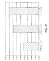
図3の下半分に、低温側の温度または低温側の作動媒体の温度変化303、304、306、308、ならびに高温側の作動媒体の高温側の温度310、312、314が示されている。
The lower half of FIG. 3 shows the low temperature or the
低温側の作動媒体315は、入り口の低温側熱交換器302に進入し、この熱交換器を通過する。入り口の低温側熱交換器302を通過する際の作動媒体の温度の低下303が、低温側温度曲線Tcの低下303によって示されている。低温側の作動媒体315は、温度低下304によって示されているとおり、次のステージの低温側熱交換器305を通過するときにさらに冷却され、さらに温度低下306を伴って第3の低温側熱交換器307を通過する。低温側の作動媒体315は、温度308の低温流体316として出る。同様に、高温側の作動媒体317は、第1または入り口の高温側熱交換器309に進入し、図3の高温側温度曲線THによって示されているとおり第1の温度310にて出る。高温側の作動媒体は、図2において述べたように段階的にアレイ300を通過して進んで、漸進的に高温になり、最後に出口の高温側熱交換器313を通過した後に、318においてより高い温度314で、高温の作動流体として出る。ステージ(すなわち、TEモジュールおよび熱交換器)の数を増すことによって、冷却および加熱力の大きさを増すことができ、それぞれの熱交換器によって生み出される温度変化を小さくすることができ、さらに/またはアレイを通過する媒体の量を増すことができることを、容易に見て取ることができる。米国特許第6,539,725号に教示されているように、ステージの数を増やすことによって、度合いは徐々に小さくなるが、効率を高めることも可能である。
The low temperature
実験および上述の説明が、図2および3の構成によって達成することができる熱絶縁ならびに漸進的な加熱および冷却が、大きな効率向上をもたらすことができ、したがって重要であることを示している。そのようなシステムによって、100%を超える向上が、実験室での試験において達成されている。 Experiments and the above description indicate that the thermal insulation and gradual heating and cooling that can be achieved with the configurations of FIGS. 2 and 3 can provide significant efficiency gains and are therefore important. With such a system, an improvement of over 100% has been achieved in laboratory tests.
図4Aが、3つのTEモジュール402、4つの熱交換器403、および2つの導管405を、図2および3に記載のとおりに構成して備えるアレイ400を示している。低温側および高温側の作動流体が、それぞれ低温側導入口404および高温側導入口407において進入し、それぞれ低温側出口406および高温側出口408において出る。図4Bが、熱交換器403の一つの実施形態のさらに詳しい図である。流体媒体に適した種類として図示されている。熱交換器アセンブリ403は、導入口410および出口411を備える外側ハウジング412と、熱交換器フィン414と、流体分配マニホールド413とで構成されている。アレイ400の動作は、基本的に、図2および3において説明した動作と同じである。図4においては、TEモジュール402の数が3個であるが、任意の数であってよい。好都合には、ハウジング412が、腐食に対して保護された銅またはアルミニウムなどの適切な材料から製作され、熱伝導性である。一つの実施形態においては、熱交換器フィン414が、好都合には、TEモジュールへの境界にわたって良好な熱伝導度を達成するために、折り曲げられた銅であり、あるいはハウジング412へとはんだ付けまたはろう付けされたアルミニウムである。フィン414は、任意の形態であってよいが、好ましくは、システムにとって望まれる熱伝達特性を達成するために好適な設計であってよい。詳しい設計の指針を、W.M.KaysおよびA.L.Londonの「Compact Heat Exchangers」、第3版に見つけることができる。あるいは、穴あきフィン、平行板、ルーバーフィン、ワイヤメッシュ、など、他の任意の適切な熱交換器を使用することができる。そのような構成は、この技術分野において公知であり、図2〜11の構成のいずれにおいても使用することが可能である。
FIG. 4A shows an
図5Aは、熱交換器ステージから熱交換器への流れをもたらすための導管の接続について、図4の構成に対する代案の構成を示している。アレイ500が、第1および第2のTEモジュール501および510と、3つの熱交換器502、503、および506と、導管504とを有している。当然ながら、これまでの実施形態および構成と同様、2つの第1の側の熱交換器502、503および1つの第2の側の熱交換器506という特定の数は、これに限られるわけではなく、他の数も可能である。
FIG. 5A shows an alternative configuration to the configuration of FIG. 4 for connection of conduits to provide flow from the heat exchanger stage to the heat exchanger.
図5Bは、熱交換器502、503、506の好ましい実施形態の拡大図を示している。この図5Bに示したような熱交換器の構成は、他の実施形態においても適切であると考えられ、図2〜8および図11の構成のいずれにおいても使用可能である。そのような構成における熱交換器の1つ以上にとってのこの好都合な実施形態は、すき間513によって隔てられてセグメントに分けられた熱交換器フィン511を備える外側ハウジング516を有している。作動流体が、導入口505を通って進入し、出口508を通って出る。すき間の代案として、熱交換器を、熱交換器フィンの間に実際の物理的なすき間を有するのではなく、熱交換器が或るセクションについては熱伝導性であるが、別のセクションについては熱伝導性でないように、異方性であるように製作することができる。要点は、流れの方向において、或る単一の熱交換器セグメントと他の単一の熱交換器セグメントのステージの間に、熱絶縁を得ることにある。これは、図2〜5に記載の実施形態において熱交換器のステージを有することによってもたらされる熱絶縁に加えてもたらされる熱絶縁と考えられる。
FIG. 5B shows an enlarged view of a preferred embodiment of
好都合には、例えば加熱されることになる第1の作動流体507が、導入口505に進入し、第1のTEモジュール501に熱的に連絡している入り口または第1の熱交換器502を通って下方へと通過する。作動流体507は、底部において出て、導管504を通って次の熱交換器503へと導かれ、熱交換器503において、再び下方へと第2のTEモジュール510を通過し、高温の作動流体508として出る。好ましくは、第2の作動流体517が、導入口518を通って図5Aの底部から進入し、TEモジュール501および510の(この例では)低温側を過ぎて第3の熱交換器506を上方へと通過する。熱交換器506は、TEモジュール501および510の低温側に熱的に良好に連絡している。この配置構成によれば、作動流体507および517が、上述の米国特許第6,539,725号の教示に沿った対向流の系を形成する。
Conveniently, for example, a first working
好ましくは、図5Bに詳しく示されている熱交換器502、503、および506は、TEモジュール501、510、510の面からハウジング516を介して熱交換器フィン511(4つの分離されたセグメントにて図示されている)へと高い熱伝導性を有するように構成されている。しかしながら、それぞれの熱交換器セグメントを残りの熱交換器セグメントから熱的に絶縁するために、流れの方向においては熱伝導性が低いことが望ましい。絶縁がしっかりしており、TEモジュール501および510が、それらの垂直方向(作動流体の流れの方向)について大きな内部熱伝導性を呈さない場合、アレイ500は、熱絶縁からの利益を得、より高い効率で動作することができる。実際に、アレイ500は、あたかもより多くのTEモジュールおよびより多くの熱交換器で構成されたアレイであるかのように応答することができる。
Preferably, the
図6は、作動気体によって有益に動作するように設計されたさらに別の加熱器/冷却器・システム600を示している。加熱器/冷却器600は、TEモジュール601、602を、第1の側の熱交換器603、605および第2の側の熱交換器604に熱的に良好に連絡させて有している。空気または他の気体などの第1の作動流体606が、ダクト607、708、610によって収容され、第2の作動流体616が、ダクト615、613によって収容されている。ファンまたはポンプ609、614が、ダクト608、615内に取り付けられている。
FIG. 6 shows yet another heater /
第1の作動流体606は、導入ダクト607を通ってシステム600に進入する。作動流体606は、第1の熱交換器603を通過し、そこで例えば加熱(または、冷却)される。次いで、作動流体606は、作動流体606をダクト608を通って送るように機能するファン609を通過し、第2の熱交換器605を通過し、そこでさらに加熱(または、冷却)され、出口ダクト610から出る。同様に、空気または他の気体などの作動流体が、導入ダクト615を通って進入する。作動流体は、第2のファンまたはポンプ614によって押されて第3の熱交換器604を通過し、そこで、この例では冷却(または、加熱)される。冷却(または、加熱)された作動流体616が、出口ダクト613を通って出る。
First working
システム600は、さらなるTEモジュールならびに熱交換器および図5Bに示されるとおりに絶縁されてセグメント型熱交換器で構成される複数のセグメントを有することができる。また、追加の送り力をもたらすために、複数のファンまたはポンプを有することができる。さらに、1つのダクト(例えば、607、608)が、1つの流体を有することができ、残りのダクト613、615が、第2の種類の気体を有することができる。あるいは、片側が、液体の作動流体を有することができ、他方が気体を有することができる。このように、システムは、作動媒体が流体または液体であるかに制限されない。さらに、出口ダクト613をファンダクト609の周囲に引き回すことができることに、注意すべきである。
図7Aは、流体における有益な使用のための加熱/冷却システム700を示している。このアセンブリは、複数のTEモジュール701を、複数の第1の側の作動媒体703および複数の第2の作動媒体704とともに有している。この例では、第1の側の作動媒体703および第2の側の作動媒体704が、ディスクを形成している。第1の側の作動媒体703は、第1の側のシャフト709へと取り付けられ、第2の側の作動媒体704は、第2の側のシャフト708へと取り付けられている。次いで、シャフト708、709が、それぞれ第1の側のモータ706および第2の側のモータ705および該当のベアリング707へと取り付けられている。モータの好ましい回転方向が、矢印710および711によって示されている。
FIG. 7A shows a heating /
セパレータ717が、アレイを2つの部位へと分割すると同時に、TEモジュール701を位置決めしている。セパレータ717によって所定の位置に保持されたTEモジュール701が、第1の側の作動媒体703および第2の側の作動媒体704を交互に挟むように離間している。任意の2つのTEモジュール701について、それらモジュールは、先の実施形態と同様に、それらの低温側および高温側が互いに面するように向けられている。作動媒体703、704は、TE素子701に熱的に良好に連絡している。サーマルグリスなどが、熱電素子701と作動媒体703、704との間の境界に好都合に設けられる。グリスの目的は、作動媒体703、704の動作に関する以下の検討において明らかになる。第1の側のハウジング部714および第2の側のハウジング部715が、システム700によって調整された流体を含む。電気配線712,713が、TEモジュールのための駆動電流を供給するために、TEモジュール701へとつながっている。
A
図7Bは、図7Aのシステム700の一部を通過する断面図7B−7Bである。第1の流体721および第2の流体723が、矢印721および723によって、それらの流れの方向とともに示されている。第1の流体は、矢印722によって表わされるとおりに出、第2の流体は、矢印724によって表わされるとおりに出る。システム700は、電気配線712および713を通ってTEモジュール701へと電流を通すことによって動作する。TEモジュール701は、図2および3に示されるとおりの方法で配置され、それらの低温側および高温側を互いに面するように有している。例えば、それらの隣接する低温側が、どちらも第1の側の作動媒体703に面し、それらの高温側が、第2の側の作動媒体704に面する。セパレータ717が、TEモジュール701の位置決めという機能、および高温側をアレイ700の被冷却側から隔てる機能という二重の機能を果たす。
7B is a
動作を理解するために、例えば、第2の流体723が冷却されると仮定する。冷却は、第2の側の媒体704との熱交換によって生じる。第2の側の媒体704が回転するにつれて、第2の側の媒体704のうちで任意の所与の時点においてTEモジュール701の低温側に接している部位が、冷却される。この部位が、第2のモータ705の動作によってTEモジュール701から離れるように回転したとき、第2の媒体704が、第2の側の流体を冷却し、次いで第2の側の流体は、出口724を出る。第2の流体は、ハウジングの部位715およびセパレータ717によってアレイ700内に閉じ込められている。
To understand the operation, for example, assume that the
同様に、第1の流体721は、TEモジュール701の高温側に熱的に接する第1の側の媒体703によって加熱される。回転(矢印711によって示されている)によって、第1の媒体703の被加熱部分が移動し、そこを第1の流体721が通過でき、熱的接触によって加熱される。第1の流体721は、ハウジングの部位714およびセパレータ717の間に封じられ、出口722を出る。
Similarly, the
上述のように、熱伝導グリスまたは水銀などの液体金属を、TEモジュール701と媒体703、704との間に接触の領域において良好な熱的接触をもたらすために使用することができる。
As described above, a liquid metal such as thermally conductive grease or mercury can be used to provide good thermal contact in the area of contact between the
上述のように、図7Aおよび7Bの構成を、マイクロプロセッサ、レーザダイオード、などの外部の部品を冷却または加熱するために、好都合に使用することもできる。そのような場合には、ディスクが、そのような部品へと熱を伝達し、あるいはそのような部品から熱を伝達するために、サーマルグリスまたは液体金属などを使用して、そのような部品に接することができる。 As described above, the configuration of FIGS. 7A and 7B can also be advantageously used to cool or heat external components such as microprocessors, laser diodes, and the like. In such cases, the disk may transfer heat to such components or use thermal grease or liquid metal, etc., to transfer heat to such components. You can touch.
図7Cは、TEモジュール701が熱絶縁を達成するためにセグメントに分けられているシステム700の変種を示している。図7Cは、TEモジュール701および702が熱移動媒体704および703(この例では、回転ディスク)へと熱の力を伝達するアレイ700の一部分の詳細図を示している。移動媒体704および703が、それぞれ軸733および734を中心にして回転する。
FIG. 7C shows a variation of the
一つの実施形態においては、好都合には、作動媒体704および703が、矢印710および711によって示されるとおり反対方向に回転する。移動する媒体704、703が回転するにつれ、TEモジュール701および702の異なる部位が移動する媒体704、703に熱的に接触して熱を伝達し、移動する媒体704、703の温度を漸進的に変化させる。例えば、第1のTEモジュール726が、特定の位置において移動媒体704を加熱する。この位置の移動媒体704の材料が、移動媒体704が反時計方向に回転するにつれて、第2のTEモジュール725に接触する。次いで、この移動媒体704の同じ部位は、TEモジュール・セグメント701へと移動を続ける。反対の動作が、移動媒体703が反時計方向に回転してTEモジュール701に係合し、続いてTEモジュール725および726に係合するときに生じる。
In one embodiment, advantageously, the working
好都合には、移動媒体704、703は、半径方向および軸方向に良好な熱伝導性を有しており、角度方向、すなわち移動の方向については、熱伝導性に乏しい。この特性により、移動媒体704および708を介した伝導性による1つのTEモジュール725から別のTEモジュール726への熱伝達は最小限であり、有効な熱絶縁が達成される。
Conveniently, the moving
TEモジュールまたはセグメント701、725、726の代案として、ただ1つのTE素子またはいくつかのTE素子セグメントを代替とすることができる。この場合、TE素子701が、移動媒体703、704の移動の方向における長さに比べてきわめて薄く、かつこの方向において熱伝導性に比較的乏しいならば、TE素子は、TE素子の長さにおいて実質的な熱絶縁を呈するであろう。TE素子が熱を導き、したがって、あたかも別個のTEモジュール701で構成されているかのように熱的に応答するであろう。この特性が、移動媒体704、703において移動の方向の熱伝導性が低いことと組み合わさって、有効な熱絶縁を達成することができ、したがって性能向上をもたらす。
As an alternative to TE modules or
図7Dは、移動媒体704、703の別の構成を示しており、媒体が、スポーク727および731を有する車輪729および732の形状に構成されている。スポーク727および731の間の空間に熱交換器材料728および730が位置し、スポーク727および731に熱的に良好に接触している。
FIG. 7D shows another configuration of the moving
システム700は、図7Dに示されているさらに別の様相にて動作することができる。この構成においては、作動流体(図示されていない)が、アレイ700の軸に沿って軸方向に移動して、1つの媒体704から次の移動媒体704という順序で軸方向に、最後の媒体704を通過して出るまで移動媒体704、703を順次に通過する。同様に、別の作動流体(図示されていない)が、アレイ700を軸方向に通って個々の移動媒体703を通過する。この構成において、ダクト714および715ならびにセパレータ717が、移動媒体704、703を囲み、かつ媒体704を媒体703から分離する連続リングを形成するように形作られている。
作動流体が軸方向に流れるとき、熱の力が熱交換器材料728および730を介して作動流体へと伝えられる。好都合には、例えば高温側の作動流体が、熱交換器728を通過し、熱交換器730を通過して移動する作動流体の反対の方向にアレイ700を通過して移動する。この動作の様相においては、アレイ700が対向流の熱交換器として機能し、連続する一連の熱交換器728および730が、それらを通過するそれぞれの作動流体を漸進的に加熱および冷却する。図7Cについて述べたように、熱的に能動的な部品は、移動媒体704、703の移動の方向に有効な熱絶縁を有するように構成できるTEモジュール701であってよい。あるいは、TEモジュール701および702が、図7Cに示されているようなセグメントであってよい。後者の場合には、移動媒体704、703の外側ディスク729および732の部位を熱的に絶縁するために、移動媒体704、703の熱伝導性が移動の方向について小さいことが、さらに好都合である。
As the working fluid flows axially, heat forces are transferred to the working fluid via the
あるいは、この設計が、運動の方向の熱の絶縁を達成するために、TEモジュール701および702からの熱の伝達を受ける部位729および732に放射状の溝(図示されていない)をさらに含んでもよい。
Alternatively, this design may further include radial grooves (not shown) in
図8は、第1の側の熱交換器803と第2の側の熱交換器808との間に複数のTE素子801(斜線付き)および802(斜線なし)を有している熱電システム800の別の実施形態を示している。電源805が、電流804を供給し、配線806、807によって熱交換器808へと接続されている。システム800は、例えば図2、3、4、5、6、および7に記載のとおりにアレイ800を通って高温側および低温側の作動媒体を移動させるために、導管ならびにポンプまたはファン(図示されていない)を有している。
FIG. 8 shows a
この設計において、TEモジュール(多数のTE素子を有している)は、TE素子801および802によって置き換えられる。例えば、斜線付きのTE素子801は、N型のTE素子であってよく、斜線なしのTE素子は、P型のTE素子であってよい。この設計において、熱交換器803および808を、きわめて高い導電性を有するように構成することが好都合である。例えば、熱交換器803、808のハウジング、ならびにそれらの内部のフィン、または他の種類の熱交換器部材を、銅または他の高度に熱および電気伝導性の材料で製作することができる。あるいは、熱交換器803および808が、TE素子801および802にきわめて良好に熱的に連絡しているが、電気的には絶縁されてもよい。その場合には、電気シャント(図示されていない)を、図1に示されている方法と同様の方法(ただし、シャントが熱交換器803および808を通過して巡らされる)でTE素子801および802を電気的に接続するために、TE素子801および802の面へと接続することができる。
In this design, the TE module (having multiple TE elements) is replaced by
いずれの構成であっても、N型のTE素子801からP型のTE素子802へと通過するDC電流804が、例えば、TE素子801およびTE素子802の間に挟まれた第1の側の熱交換器803を冷却し、P型のTE素子802からN型のTE素子801へと通過する電流804が、TE素子802およびTE素子801の間に挟まれた第2の側の熱交換器808を加熱する。
In any configuration, the DC current 804 passing from the N-
アレイ800は、標準的なTEモジュールのシャント、基板、および多数の電気コネクタ配線を除去または削減できるため、最小限のサイズおよび熱損失を呈することができる。さらに、TE素子801および802が、部品が高い導電性および容量を有するように設計される場合、大きな電流に対応するヘテロ構造であってよい。そのような構成において、アレイ800は、高い熱出力密度を生み出すことができる。
The
図9は、図8に示した熱電システムと同じ全体形式の熱電システム900を示しており、P型のTE素子901およびN型のTE素子902を第1の側の熱伝達部材903と第2の側の熱伝達部材905との間に、これらの熱伝達部材に熱的に良好に接触させて備える。この構成において、熱伝達部材903および905は、熱伝導ロッドまたはヒートパイプの形態を有している。熱交換器フィン904、906などが、熱伝達部材903および905へと取り付けられ、熱的に良好に連絡している。第1の導管907が、第1の作動媒体908および909の流れを閉じ込めており、第2の導管914が、第2の作動流体910および911の流れを閉じ込めている。電気コネクタ912および913が、図8に示されているとおり交互のP型およびN型のTE素子901、902の積層へと電流を導く。
FIG. 9 shows a
動作時、例えば、電流が第1のコネクタ912を通ってアレイ900に入り、交互のP型のTE素子901(斜線付き)およびN型のTE素子902(斜線なし)を通過し、第2の電気コネクタ913を通って出る。このプロセスにおいて、第1の作動媒体908が、熱伝達フィン904(第1の熱伝達部材903を介しての伝導によって加熱されている)からの伝導によって加熱されるため、次第に高温になる。第1の導管907が、第1の作動媒体908が作動流体909として変化後の温度で出るように、第1の作動媒体908を囲んで閉じ込めている。第1の導管907の一部分が、TE素子901および902ならびに第2の側の熱伝達部材904を、第1の(この場合には高温の)作動媒体908および909から熱的に絶縁している。同様に、第2の作動媒体910は、第2の導管914を通って進入し、第2の側の熱交換器906を通過するときに(この例では)冷却され、冷却された流体911として出る。TE素子901、902が、第2の側の熱交換部材905、したがって熱交換器フィン906に、冷却をもたらす。第2の側の導管914が、第2の(この例では冷却される)作動媒体910を閉じ込め、アレイ900の他の部分から絶縁するように機能する。
In operation, for example, current enters the
図8−9の実施形態においては、個々のTE素子について述べたが、TEモジュールでTE素子901、902を置き換えてもよい。さらに、特定の状況においては、TE素子901、902を熱伝達部材903、905から電気的に絶縁し、シャント(図示されていない)を通って電流を通すことが好都合であるかもしれない。また、熱交換器904、906は、システムの機能にとって好都合な任意の設計であってよい。他の実施形態のように、図8および9の構成が、比較的容易に製造できるシステムをもたらすとともに、熱絶縁からの効率向上ももたらすことを、理解できるであろう。例えば、図8において、P型およびN型の熱電素子の間に交互に位置する熱交換器808、803は、より低温またはより高温の熱交換器の種類であるが、お互いから無理なく熱的に絶縁され、PおよびN型の熱電素子を互いに無理なく熱的に絶縁する。
Although the individual TE elements have been described in the embodiment of FIGS. 8-9, the
図10は、熱絶縁を提供する別の熱電アレイ・システム(1000)を示している。好都合には、この構成は、除湿、または凝結物、霧、凝縮可能な蒸気、反応生成物、などを除去して、媒体を元の温度よりも若干高い温度へと戻すために、同じ媒体の冷却および加熱を利用するシステムの機能を実行することができる。 FIG. 10 illustrates another thermoelectric array system (1000) that provides thermal isolation. Conveniently, this configuration is suitable for dehumidification or removal of condensate, mist, condensable vapors, reaction products, etc. to return the medium to a slightly higher temperature than the original temperature. Functions of the system that utilize cooling and heating can be performed.
システム1000は、低温側熱伝達素子1003および高温側熱伝達素子1004が組み入れられた交互のP型のTE素子1001およびN型のTE素子1002の積層で構成されている。図示の実施形態においては、熱交換器フィン1005、1006が、低温側熱伝達素子1003および高温側熱伝達素子1004の両者に設けられている。低温側の導管1018および高温側の導管1019が、アレイ1000において作動流体1007、1008、および1009を案内する。ファン1010が、アレイ1000を通って作動流体1007、1008、および1009を引っ張る。好ましくは、低温側の絶縁1012が、低温側を通って移動する作動流体1007をTE素子の積層から熱的に絶縁し、高温側の絶縁1020が、好ましくは、高温側を通って移動する作動流体をTE素子の積層から熱的に絶縁する。バッフル1010などが、低温側と高温側とを隔てている。一好ましい実施形態においては、バッフル1010が、作動流体1021を通過させるための通路1010を有している。同様に、一つの実施形態においては、流体の通路1017が、流体1016が高温側の流路へと進入できるようにしている。
The
スクリーン1011または他の多孔質の作動流体流リストリクタが、アレイ1000の低温側を高温側から隔てている。凝縮物、固体凝固物、および液体1013などが、アレイ1000の底部にたまり、バルブ1014を通って口101から出ることができる。
A
TE素子1001および1002を通過する電流(図示されていない)が、図9の説明において述べたように、低温側の作動媒体熱伝達素子1003を冷却し、高温側の熱伝達素子1004を加熱する。動作時、作動流体1007が低温側を下るとき、作動流体1007からの凝結物、水分、または他の凝縮物1013を、アレイ1000の底部に集めることができる。必要に応じ、バルブ1014を開いて、凝結物、水分、または凝縮物1013を、口1015を通って取り除くことができ、あるいは他の任意の適切な手段によって抽出することができる。
A current (not shown) passing through the
好都合には、作動流体1021の一部を、バイパス通路1020を通って低温側から高温側へと通過させることができる。この設計によれば、低温側の流体1007のすべてが流量制限器1011を通過するのではなく、代わりに、高温側の作動流体の温度を局所的に低下させて一部の状況下でアレイ1000の熱力学的効率を改善するために使用することができる。バイパス通路1020と流量制限器1011との間の流れの適切な割合は、システムの流れの特性を適切に設計することによって達成される。例えば、流れを制御するためにバルブを取り入れることができ、特定の通路を開放または閉鎖することができる。いくつかの用途においては、流量制限器1011が、液体または気体の作動流体1008から凝結物を取り除き、あるいは気体の作動流体1008からミストまたは霧を取り除くためのフィルタとしても機能することができる。
Conveniently, a portion of the working
好都合には、さらなる高温側の冷却剤1016が、やはり高温側の作動流体の温度の低下またはアレイ1000の効率の向上という目的のために、横通路1017を通ってアレイ1000に進入できる。
Conveniently, additional
この構成は、流量制限器にきわめて冷たい状態を生み出すことができ、作動流体1008が、かなりの大きさの凝結物、凝縮物、または水分の除去能力を有することができる。別の動作の様相においては、ファン1010への動力を逆にして、システムを作動流体を加熱し、低温状態へと戻すように動作させることができる。これは、加熱プロセスによって形成される反応生成物、凝結物、凝縮物、水分、などを取り除くために、好都合でありうる。一好都合な実施形態においては、流量制限器1011ならびに/あるいは熱交換器1005および1006が、システムにおいて生じうるプロセスを増進し、変更し、可能にし、防止し、あるいは他の方法で左右する触媒特性を有することができる。液体の作動流体においては、好都合な性能を達成するために、1つ以上のポンプでファン/モータ1010を置き換えることができる。
This configuration can create a very cool condition for the flow restrictor, and the working
図11は、図2および3と同様の設計であるが、作動媒体がシステムを通過する交互の経路を有している熱電アレイ1100を示している。アレイ1100は、TEモジュール1101を熱交換器1102の間に分布させて有している。複数の導入ポート1103、1105、および1107が、アレイ1100を通って作動媒体を導く。複数の出口ポート1104、1106、および1108が、アレイ1100から作動媒体を導く。
FIG. 11 shows a
動作時、例えば、冷却されるべき作動媒体が、第1の導入ポート1103において進入し、いくつかの熱交換器1102を通過することによって徐々に(この例では)冷却され、第1の出口ポート1104を通って出る。アレイ1100から熱を取り去る作動媒体の一部は、第2の導入ポート1105を通って進入し、熱交換器1102を通過し、このプロセスにおいて徐々に加熱され、第2の出口ポート1106を通って出る。
In operation, for example, the working medium to be cooled enters the
熱を取り去る作動媒体の第2の部分は、第3の入口ポート1107に進入し、熱交換器1102のうちのいくつかを通過するときに加熱され、第3の出口ポート1108を通って出る。
The second portion of the working medium that removes heat enters the
この設計では、この例では高温側の作動媒体が2つの位置において進入し、TEモジュール1101にわたって得られる温度差が、平均で、作動媒体がただ1つのポートにて進入する場合に比べてより低くなるため、第1の導入ポート1103から第1の出口ポート1104へと通過する低温側の作動媒体を効率的に冷却できるようになる。平均で、平均の温度勾配がより小さい場合、多くの状況において、得られるシステム効率はより高くなる。第2および第3の導入ポート1105および1107を通過する相対の流量を、所望の性能を達成するため、または外部の条件の変化に応答するために、調節することができる。例として、第3の導入ポート1107を通過する流量がより多く、さらに最も効率的には、この部位を通過する流れの方向が逆であって、すなわち第3の出口ポート1108が入り口であると、第1の出口ポート1104を出る低温側の作動媒体の出口温度をより低くすることができる。
In this design, the working medium on the high temperature side enters at two locations in this example, and the temperature difference obtained across the
従来からの熱電気100の基礎をなす基本的接続が、図1Cにさらに詳しく示されている。上述のように、P型の素子110およびN型の素子112は、この技術分野において周知の種類の素子である。P型およびN型のTE素子110および112にシャント106が取り付けられ、熱的に良好に連絡している。一般に、図1Aに示されているように、多数のこのようなTE素子およびシャントが一緒に接続されて、TEモジュールが形成される。
The basic connections underlying the conventional thermoelectric 100 are shown in more detail in FIG. 1C. As described above, P-
電流方向におけるTE素子110、112の長さは、LC116である。その奥行きはBC117であり、その幅はWC118であり、その離隔距離はGC120である。シャント106の厚さは、TC109である。
The lengths of the
この技術分野において周知のとおり、寸法BC、WC、およびLCのほか、TE材料の性能指数Z、電流122および動作温度が、冷却量、加熱量、または生成される電力量を決定する(たとえば、Angrist,S.W.の「Direct Energy Conversion」、第3版、1997年、第4章を参照)。 As is well known in the art, the dimensions B C , W C , and L C , as well as the TE material figure of merit Z, current 122 and operating temperature determine the amount of cooling, heating, or amount of power generated. (See, eg, “Direct Energy Conversion” by Angrist, SW, 3rd edition, 1997, Chapter 4).
図12に示される設計は、図1の従来の構成を必要となる熱電材料の量およびシャント106における寄生抵抗の大きさを削減する態様に改変したものである。TE構成1200は、シャント1203および複数の第2の側のシャント1204との間に直列に挟まれた交互の導電型の複数の第1の側のTE素子1201、1202を有するため、電流1209は、図1Cの場合のように奥行きに略平行ではなく、シャントの奥行きBBおよび幅WBに対して垂直に通過する。図12の設計においては、ROBに対するRPBの比φBは、
The design shown in FIG. 12 is a modification of the conventional configuration of FIG. 1 to reduce the amount of thermoelectric material and the magnitude of parasitic resistance in the
であり、ここで And here
であり、したがって And therefore
であって、
TBは、シャントの厚さであり、
LBは、TE素子の長さであり、
ρSBは、シャントの抵抗率であり、
BBは、TE素子およびシャントの有効な奥行きであり、
WBは、TE素子およびシャントの有効な幅である。
Because
T B is the thickness of the shunt,
L B is the length of the TE elements,
ρ SB is the resistivity of the shunt,
B B is the effective depth of the TE element and shunt,
W B is an effective width of the TE elements and shunts.
φCがφBに等しく設定される場合には、寄生電気抵抗損失は、図1Cおよび図12の構成の性能に同じ比例的な影響を有する。比較の目的のために、2つの構成の材料特性が同一であると仮定すると、 If φ C is set equal to φ B , the parasitic electrical resistance loss has the same proportional effect on the performance of the configurations of FIGS. 1C and 12. For comparison purposes, assuming that the material properties of the two configurations are the same:
![]()
![]()
であり、あるいはBに式(9)および(12)を用いて、 Or using equations (9) and (12) for B,
である。 It is.
今日の典型的な熱電モジュールにおいては、 In today's typical thermoelectric module,
であり、 And
と仮定すると、 Assuming
である。 It is.
したがって、長さLBは、LCの1/6.4となることができ、図12の設計において結果として生じる抵抗損失は、従来のTEモジュールの抵抗損失を超えない。これが事実であり、他のすべての損失が無視し得るか、または比例的に減少する場合には、図12の構成を用いるTEシステムは、図1Cの設計と同じ動作効率を有するが、LB=LC/6.4である。 Therefore, the length L B can be 1 / 6.4 of L C and the resulting resistance loss in the design of FIG. 12 does not exceed the resistance loss of the conventional TE module. This is the case, whether all other losses negligible, or in the case of reduced proportionally, the TE system using the configuration of FIG. 12 has the same operation effectiveness as the design of FIG. 1C, L B = L C /6.4.
この新たな構成の体積を、図1Cの体積と比較することができる。同じqOPTの場合には、面積比が同じままでなければならず、したがって The volume of this new configuration can be compared with the volume of FIG. 1C. For the same q OPT , the area ratio must remain the same, so
であり、 And
であるから Because
である。 It is.
2つの熱電材料の体積比は、 The volume ratio of the two thermoelectric materials is
であり、 And
である。 It is.
したがって、これらの仮定によれば、必要とされるTE材料が1/41である。この大幅な削減の可能性は、行なった仮定の精密さゆえに完全には実現されない可能性があるが、それでも用いられるTE材料の量、ひいてはコストおよびサイズを削減するうえで、きわめて有利となりうる。 Therefore, according to these assumptions, the TE material required is 1/41. This possibility of significant reduction may not be fully realized due to the precision of the assumptions made, but it can still be very advantageous in reducing the amount of TE material used, and hence cost and size.
図12のTEスタック構成1200は、長さLB1205のP型TE素子1201およびN型TE素子1202を有する。電流の流れの方向は、矢印1209によって示されている。TE素子は、奥行きBBおよび幅WBを有する。電流の方向において、P型TE素子1201とN型TE素子1202との間に、第2の側のシャント1204(「PNシャント」)が位置している。電流の方向において、N型TE素子1202とP型TE素子1201との間には、第1の側のシャント1203(「NPシャント」)が存在している。PNシャント1204は、スタック1200からNPシャント1203とはおおむね逆方向に延びている。180°以外の角度も好都合である。
The
適切な電流1209が図示の方向に通過する場合には、NPシャント1203が冷却され、PNシャント1204が加熱される。この構成によって、構成1200における寄生電気抵抗損失は、典型的には、TE素子の寸法が同一である場合の図1の従来の構成100に比べて小さい。したがって、2つの構成における寄生的な電気損失の比を一致させるようにTEの長さLB1205が短くされる場合、TEの長さLB1205がより短くなり、図12の構成は。好都合に図1の構成よりも高い出力密度で動作することができる。結果として、図12の構成1200は、図1の従来の設計の場合よりも使用される熱電材料が少なく、よりコンパクトにすることができる。
If the appropriate current 1209 passes in the direction shown, the
シャント1203、1204は、TE素子1201、1202から遠ざかるように熱出力を伝達する機能、ならびに作動流体などの外部の物体または媒体と熱出力を交換する機能という2つの機能を果たすことができる。
The
熱交換器1302を形成するために組み合わせられるシャントの好ましい実施形態1300の図が、図13Aに示されている。好ましくは、少なくとも1つのTE素子1301が、熱交換シャント1302の盛り上がった電極面1303にはんだなどによって電気的に接続される。好都合には、TE素子1301の取り付けおよび低い抵抗での電流の流れを促進するために、シャント1302を、主にアルミニウムなどの優れた熱導体から構成でき、銅などの導電率の高い材料で構成される一体の被覆材料1304、1305を有することができる。
A diagram of a
図13Bは、図13Aの熱電シャント1302およびTE素子1301から構成されるスタック熱電アセンブリ1310について、一部分の詳細な側面図を示している。盛り上がった電極面1303を備えた複数のシャント1302が、交互の導電型のTE素子1301に電気的に直列に接続される。
FIG. 13B shows a detailed side view of a portion of the stacked
適切な電流が印加されるときに、シャント1302は、交互に加熱および冷却される。生成される熱出力は、シャント1302によってTE素子1301から運び去られる。好都合には、盛り上がった電極1303が、TE素子1301を取り付けるための信頼性が高く、低コストで、安定な表面をもたらす。実際には、複数のこれらのアセンブリ1310のスタックを設けることができる。スタックのアレイを用いて、熱絶縁もさらに促進することができる。
When an appropriate current is applied, the
電極1303を、好都合には、はんだがTE素子1301を短絡することがないように形作ることができる。また、電極1303を、好都合には、接触面積を制御し、したがってTE素子1301を通過する電流密度を制御するように、形成することができる。
シャント熱交換器1400の一部分の例が、図14に示されている。この部分1400は、熱伝達を促進するために、表面積を増大させている。TE素子1401が、好ましくは図13Aに示したように構成され、あるいは本明細書の他の実施形態のように構成されたシャント1402へと取り付けられる。フィンなどの熱交換器1403、1404が、シャント1402にろう付けなどによる良好な熱接触によってシャント1402に取り付けられる。この実施形態において、作動流体1405が、熱交換器1403、1404を通過する。
An example of a portion of a
好都合には、シャント部分1400は、作動流体1405が熱交換器1403、1404を通過するときに熱出力が効率的に伝達されるように構成される。さらに、図12および図13Bに記載したようなスタックへと組み込まれる場合、シャント1402および熱交換器1403、1404の材料のサイズおよび比率は、動作効率を最適化するように設計される。好都合には、熱交換器1403、1404はルーバ付きであってよく、多孔性であってよく、あるいはW.M.KaysおよびA.L.Londonの「Compact Heat Exchangers」、第3版に記載されている熱交換器など、上述の目的を達成する他の任意の熱交換器設計に置き換えられてもよい。熱交換器1403、1404を、エポキシ、はんだ、ろう付け、溶接、または良好な熱接触を提供する任意の他の取り付け方法によって、シャント1402へと取り付けることができる。
Conveniently, the
シャント・セグメント1500の別の実施例が、図15に示されている。シャント・セグメント1500は、複数のシャント素子1501、1502、1503、および1504で構成される。シャント素子1501、1502、1503、および1504は、互いの上に折り畳まれてもよく、ろう付けされてもよく、リベットで締められてもよく、あるいは電流1507を通すための電気抵抗の低い経路をもたらし、TE素子1506からシャント1501、1502、1503、および1504への熱抵抗を低くするための経路をもたらす任意の他の方法で接続されてもよい。TE素子1506は、好都合には、ベース部分1505またはその付近でセグメント1500へと取り付けられる。
Another embodiment of the
シャント・セグメント1500は、図14のシャント・セグメント1400の代替設計を示している。シャント・セグメント1500を、図12および13に示されているようなスタックに構成することができ、次いで、所望であれば、スタックのアレイに構成することができる。図14および15の構成はいずれも、これらの設計から製作されたTEシステムの人件費を下げるために、自動的に組み立てることが可能である。
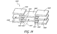
また、シャント・セグメントを、図16に示されるようなスタック・アセンブリ1600へと形成することができる。中央シャント1602は、中央シャント1602の対向する側のそれぞれの端部にある反対の導電型の第1の側および第2の側のTE素子1605のそれぞれの端部に同一の導電型の第1の側のTE素子1601を有している。シャント1602のスタックを形成するために、図16に示すように、それぞれの中央シャント1602の間に、右側シャント1603および左側シャント1604が配置される。右側シャント1603は、左端部がTE素子1601、1605の間に良好な熱接触および電気接触で挟まれるように配置される。同様に、左側シャント1604は、右端部がTE素子1601、1605の間に良好な熱接触および電気接触で挟まれるように配置される。シャント1602、1603、および1604は、交互に積み重ねられ、電気的に接続されてシャント・スタック1600を形成する。第1の作動流体1607および第2の作動流体1608が、アセンブリ1600を通過する。当然ながら、図16に示され、本明細書に記載されるスタック構成の実施形態において、スタックを、スタック中のさらに多くのシャント素子で構成でき、おそらくはそのようである。スタック・アセンブリ1600のほんの一部が、読者の理解のために示されているにすぎない。そのようなスタックをさらに繰り返されることが、図から明白である。さらに、作動流体の方向に熱絶縁されたさらなるスタックを設けることが可能である。
The shunt segments can also be formed into a
適切な電流がTE素子1601、シャント1605、1604を通って一方向に印加されるときに、中央シャント1602は冷却され、左側および右側シャント1604および1606は加熱される。結果として、中央シャント1602を通過する第1の作動流体1607は冷却され、右側および左側シャント1603、1604を通過する第2の作動流体1608は加熱される。スタック・アセンブリ1600は、流体を調整するための半導体ヒートポンプを形成する。スタック1600が、少数または多数のセグメントを備えることができ、それによって、印加される電流および電圧の量、構成要素の寸法、およびアセンブリに組み込まれるセグメントの数に応じて、さまざまな出力レベルで動作することができることに留意することが重要である。そのようなスタックのアレイもまた、好都合でありうる。そのようなスタック1600のアレイが用いられる状況において、効率を向上させるために、米国特許第6,539,725号に記載されているように、流体の流れの方向に熱絶縁をもたらすことが好ましいと考えられる。
When an appropriate current is applied in one direction through
また、性能を向上させるために、シャント1602、1603、1604を、これらに限られるわけではないが図14および15に示した形状など、他の形状によって置き換えることができることを理解すべきである。
It should also be understood that the
図16に示したスタック・アセンブリ1600の変種が、図17に示されている。この構成では、TEアセンブリ1700は、略円形形状を形成するために右側シャント1703および左側シャント1704から構成される。好都合には、右側シャント1703は、部分円を形成するように構成され、左側シャント1704も同様である。好ましい実施形態において、動作中に低温になるシャントは、その装置の特定の目的に応じて、高温になるシャントより大きくても、あるいは小さくてもよい。中央の流れの部分を形成するために、実質的に円形の構成は必要ではなく、図17に示されたシャントセグメントの他の構成を用いることも可能であることに留意すべきである。たとえば、右側シャントは半矩形または半四角形であってもよく、左側シャント1704は半矩形または四角形であってもよい。同様に、一方の側は多面であってもよく、一方の側はアーチ型であってもよい。シャントの具体的な形状は変更可能である。図16に関して説明したように、交互に配置される導電型からなるTE素子1701および1702は、スタック・アセンブリ1700において電気的に直列に接続される。流体1712は、シャント1703、1704によって形成される中央領域の中を流れることが好ましい。流体1712の第1の部分1707は、右側シャント1703同士の間を通り、作動流体1712の第2の部分1706は、左側シャント1704同士の間を通る。電源1708は、電線1712、1713によってTE素子に電気的に接続され、電線は接点1710および1711でスタックに接続される。ファン1709を、スタックの一端(または両端)に取り付けることができる。ポンプ、またはブロワなども同様に使用することが可能である。
A variation of the
電力がファン1709に印加されると、ファン1709は、アセンブリ1700を通って作動流体1712を送る。右側シャント1703が冷却されるような極性で電流が供給されるとき、作動流体1712の第1の流体部分1707は右側シャント1703を通過するにつれて冷却される。同様に、作動流体の第2の部分1706は、加熱された左側シャント1704を通過するにつれて加熱される。アセンブリ1700は、単一のコンパクトな冷却器/加熱器を形成し、その構成において用いられるシャント1703、1704の数によって、容量および全体サイズを調整することができる。シャント1703、1704は角ばっていてもよく、楕円形または任意の他の好都合な形状であってもよいことは明白である。さらに、シャントは、図14、図15に示された設計または任意の他の有用な構成であってもよい。
When power is applied to
図12、14、15、16、および17の熱電システムの一つの実施形態において、図18に示されるようなアレイの1つ以上の部分に、2つ以上のTE素子を用いることができる。この実施例において、TE素子1801、1804は、シャント1802、1803のそれぞれの側で盛り上がった電極面1804に接続される。
In one embodiment of the thermoelectric system of FIGS. 12, 14, 15, 16, and 17, more than one TE element can be used in one or more portions of the array as shown in FIG. In this embodiment, the
電気的に並列である複数のTE素子1801は、機械的安定性を増大し、熱出力をさらにうまく分散し、システムに電気的冗長性を追加することができる。3つ以上のTE素子1801を並列に用いることができる。
一定の用途において、図12〜13によるシャントの露出部分を電極部分から電気的に絶縁することが望ましい。そのようなシャントの一実施例が、図19に示されている。この実施形態において、電気絶縁体1905は、シャント1900の熱交換部分1904からシャント1900の電極部分1903を分離する。TE素子1901、1902は、電極部分1903に装着されることが好ましい。
In certain applications, it is desirable to electrically isolate the exposed portion of the shunt according to FIGS. 12-13 from the electrode portion. One example of such a shunt is shown in FIG. In this embodiment, the
動作時に、銅などの導電性および熱伝導率の高い材料から構成される電極部分1903を介して対向する導電型のTE素子1901、1902の間に電位が印加されることが有利である。TE素子1901、1902によって生成される熱出力は、シャント電極に沿い、電気絶縁体1905を通り、シャント1900の熱交換部分1904に伝導される。電気絶縁体1905はアルミナ、熱伝導エポキシまたは同種のものなどのきわめて優れた熱導体であることが有利である。図示されているように、電気絶縁体1905によって形成される境界面の形状は、熱抵抗を最小限に抑えるために、浅い「V」字形状である。適切に低い界面熱抵抗を有する任意の他の形状および材料の組み合わせもまた、用いることができる。そのようなシャント1900のスタックを前述のように用いることができる。
In operation, it is advantageous to apply a potential between opposing
電気絶縁の別の形態が、図20の平面図に示される別のシャントセグメント・アセンブリ2000に示されている。第1のTE素子2001は、シャントセグメント・アレイ2000の左側シャント2003に接続され、第2のTE素子2002は、シャントセグメント・アレイ2000の右側シャント2004に接続される。電気絶縁体2005は、左側シャントセグメント2003と右側シャントセグメント2004との間に配置される。
Another form of electrical isolation is shown in another
図20に示される構成は、シャント2000全体の機械的完全性を保持すると同時に、TE素子2001とTE素子2002との間に電気絶縁を提供する。図示されたようなこの構成において、電気絶縁体2005は特に良好な熱伝導率を提供する必要はない。電気絶縁体2005がTE素子2001とTE素子2002との間のおおむね中央に配置されるのであれば、熱出力源であるTE素子2001および2002は、異なるレベルで左側シャントセグメント2003および右側シャントセグメント2004を冷却または加熱することができるためである。2つのTE素子2001および2つの第2のTE素子2002が示されているが、それぞれの側により大きなTE素子またはより多数のTE素子を用いることができることに留意すべきである。2つの第1のTE素子2001および2つの第2のTE素子2002は、充分に安定な機械構造を図示するために選択されているにすぎない。また、所望の電流経路に応じて、第1のTE素子2001および第2のTE素子2002は異なる導電型である必要はないが、異なる導電型であってもよいことも留意すべきである。
The configuration shown in FIG. 20 provides electrical insulation between
シャント2100内の電気絶縁を達成する別の方法が、図21に示されている。2つの第1のTE素子2101を有するシャント部分2103は、2つの第2のTE素子2102を有する第2のシャント部分2104に機械的に取り付けられる。電気絶縁体2106は、間隙2105によって互いから離隔されるシャント部分2103および2104に機械的に取り付けられる。
Another way of achieving electrical isolation within
機械的な取り付け2106が、TE素子2101とTE素子2102との間のほぼ中央に配置され、TE素子2101および2102が、ほぼ等しい熱出力を生成する場合には、電気絶縁体2106は優れた熱導体である必要はない。TE素子2101および2102はそれぞれ、それぞれのシャント部分2103および2104に熱出力を提供する。電気絶縁体2106は、裏面粘着式のカプトンテープ、射出成形プラスチック、熱溶融型接着剤または任意の他の適切な材料であってもよい。図21の平面図に示されているように、シャント部分2103、2104は、重ね接合を形成するために重ね合わせない。エポキシまたは他の電気絶縁結合剤によるそのような接合もまた可能である。
If the
図22の平面図に示される別のシャントセグメント・アレイ2200は、矩形のTEアレイ2200中に電気的に絶縁されたシャントセグメントを有する。第1のTE素子2201は、第1のシャント部分2202に熱接触され、第2のTE素子2203は、第2のシャント部分2204に熱接触される。各シャント部分は、間隙2210、2211によって他のシャント部分から電気的に分離される。アセンブリの左側にある電気絶縁体2208、中央にある絶縁体2207、および右側にある絶縁体2209が設けられることが好ましい。矢印2212は、作動流体が流れる方向を示す。この構成は、電気絶縁がない類似のアレイより高い電圧かつ低い電流で動作することができる。図20に関して述べたように、第1のTE素子2201および第2のTE素子2203は異なる導電型である必要はないが、異なる導電型であってもよい。これは、所望の電流の方向に左右される。しかし、TE素子2202、2203は、異なる電位である場合がある。
Another
間隙2210は、第1のシャント部分2202を互いから効率的に熱絶縁し、第2のシャント部分2204を互いから効率的に熱絶縁するために機能する。同様に、側部の絶縁体2208、2209は、熱絶縁および電気絶縁の両方を提供すると同時に、シャントに共に機械的に取り付けられる。中央の絶縁体2207は、その長さに沿って電気絶縁および熱絶縁を提供する。したがって、アレイ2200は、米国特許第6,539,725号に記載されているように、矢印2212の方向において熱絶縁を形成するように構成される。この構成は、電気絶縁がない類似のアレイより高い電圧かつ低い電流で動作することができる。
The
おおむね図22に示した形式のシャントセグメント・アレイを用いる冷却システム2300が、図23に示されている。冷却システム2300は、テープなどの電気絶縁材料2320によって機械的に接続される内側シャントセグメント2301、2302を有する。内側シャントセグメント2302は、電気的かつ熱的な絶縁材料2321によって機械的に接続される。同様に、内側セグメント2301は、電気的かつ熱的な絶縁材料2307によって機械的に接続される。内側シャントセグメント2301、2302は、図22に記載した態様では端部のTE素子(図示せず)に別々に接続される。TEは、内側シャントセグメント2301、2302とそれぞれの外側シャントセグメント2303、2305との間のスタックに挟まれる。中央のシャントセグメント2301は、左外側シャントセグメント2305に別々に接続され、内側シャントセグメント2302は右外側シャントセグメント2303に接続される。右外側シャントセグメント2303は同様に、内側シャントセグメント2302を接続する電気絶縁材料2321に類似の電気的かつ熱的な絶縁材料2322によって機械的に接続されることが好ましい。左外側シャントセグメント2305も、同様に機械的に接続される。ハウジング2311は、シャントセグメントおよびTEのスタック・アレイを保持する。端子2312および2314は、内部セグメント2301に電気的に接続される。同様に、端子2315および2316は、内側シャントセグメント2302に接続される。熱的かつ電気的絶縁スペーサ2309、2310が、それぞれの内側セグメントと外側セグメントとの間に配置されることが好ましい。
A
第1の作動流体2317は内側領域を通過し、第2の作動流体2318、2319は外側領域を通過する。適切な極性および大きさの電圧が端子2312と端子2314との間、および端子2315と端子2316との間に印加されるときに、内側シャントセグメント2301、2302が冷却される。また、外側シャントセグメント2303、2305が加熱される。したがって、内側領域を流れる作動流体2317が冷却され、外側シャントセグメント2303、2305を流れる作動流体2318、2319が加熱される。ハウジング2311および絶縁体2309、2310は、加熱される流体2318、2319から冷却される流体2317を収容して隔てる。
The first working
システム2300における各スタックに電圧を印加するための電気接続は、高電圧で動作するために直列であってもよく、約1/2の電圧で動作するために直列/並列であってもよく、約1/4の電圧で動作するために並列であってもよい。内側作動流体2317を加熱し、外側作動流体2318、2319を冷却するために、極性は逆であってもよい。作動流体2317、2318、2319が流れる方向にさらに多くのセグメントを用いて、さらに高い電圧で動作し、結果として生じるさらに有効な熱絶縁によりさらに高い効率を達成することが可能である。
The electrical connections for applying a voltage to each stack in
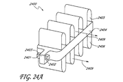
熱絶縁による性能の向上を達成する別のコンパクトな設計は、図24Aおよび図24Bに示されているように組み合わせられたシャントおよび熱伝達セグメント2400を用いる。この設計は図14の設計にきわめて類似しているが、TE素子2401、2402が流体の流れの全体的な方向に整列されている点が異なる。対向する導電型のTE素子2401、2402がシャント2404の延在部2403に接続される。フィンなどの熱交換器2405、2406が、シャント2404と良好な熱接触状態にあることが好ましい。作動流体2409は、電流の方向に応じて、熱交換器2405、2406を流れるにつれて加熱または冷却される。
Another compact design that achieves improved performance through thermal insulation uses a combined shunt and
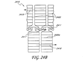
図24Bは、図24Aに示されているようなTEシャントセグメント2400からなるスタック2410の一部分を示す。電流2417は、矢印によって示される方向に流れる。複数の第1の側のシャント2400および複数の第2の側のシャント2400aが、TE素子2411に接続される。第1の作動流体2418は、スタック2410の下部分に沿って図24Aの第2の側のシャント2400aにある熱交換器を通って流れ、作動流体2419は、第1の側のシャント2400の熱交換器を通って逆方向に流れることが有利である。
FIG. 24B shows a portion of a
適切な電流2417が印加されると、スタック2410の上部分は、1つのシャントセグメントから次のシャントセグメントに流れるにつれて、流体2419を徐々に冷却し、下部分は、1つのシャントセグメント2400aから次のシャントセグメントに流れるにつれて、流体2418を徐々に加熱する。
When the appropriate current 2417 is applied, the upper portion of the
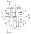
代わりとなるTEスタック構成2500が、図25Aに示されている。このTEスタックは、電流2512の方向に略垂直に流れる作動流体2513に関して熱絶縁という利点を達成する。第1のシャント2502は、第1のTE素子2501に電気的に接続され、熱交換器2503、2504と良好な熱接触状態にある。第1の側の第2のシャント2506は同様に、熱交換器2508と良好な熱接触状態にあり、第1の側の第3のシャント2505は熱交換器2507と良好な熱接触状態にある。各第1の側のシャント2502、2506および2505の間には、交互に配置されるタイプのTE素子2501が点在し、図12と同様に、第2の側のシャント2509、2510および2511は、略逆方向に突出している。第2の側のシャント2509、2510および2511は、完全には示されていないが、おおむね同じ形状であり、第1の側のシャント2502、2506および2505と同一の空間的関係を有する。作動流体2513は、矢印によって示されるようにスタック・アセンブリの中を通り抜ける。適切な電流がTE素子を通って垂直に印加されると、第1の側のシャント2502、2505および2506は加熱され、第2の側のシャント2509、2510および2511は冷却される。作動流体2513は最初に熱交換器2507を、次に熱交換器2508を、最後に熱交換器2503を流れるにつれて、徐々に加熱される。完全なスタック・アセンブリが電流の方向においてアレイ2500の反復部分を有し、熱交換器2503の一番上が別のアレイ部分の次に連続する熱交換器2504の下に接近して離隔されるように組み立てられる。作動流体2513が流れる方向における熱絶縁は、容易に明らかである。
An alternative
図25Bは、図25Aに示されるアレイ部分2500の平面図である。交互に配置される導電型の複数のTE素子2501の冷却は、複数の第1の側のシャント2502、2506、2505および複数の第2の側のシャント2511、2509、2510によって分散されるため、第1の側のシャント2502、2506および2505は、第2の側のシャント2511、2509および2510と交互に配置される。シャントは、間隙2534によって隔てられ、各シャント用の熱交換器と良好な熱接触状態にある。第1の作動流体2531は右から左に向かって上部分に沿って流れ、作動流体2532は左から右に向かって下部分に沿って流れることが有利である。電流がTEおよびシャントを流れる場合を除き、熱および電気の絶縁体2533は、シャントの各対の間に設けられることが好ましい。
FIG. 25B is a plan view of the
適切な電流がアレイ2500を流れるとき、たとえば、作動流体2531は徐々に加熱され、作動流体2532は徐々に冷却される。絶縁体2533は不必要な熱損失を防止し、作動流体2531、2532が混合するのを防止する。図示されているように、アレイ2500は、対向流モードで動作し、熱絶縁を用いて性能を向上する。同じアレイ2500は、平行流モードにおいて同一の方向に移動する作動流体2531、2532によって動作することができ、依然として性能を向上するために熱絶縁という利点を有する。いずれの場合も、TE素子2521がすべて同一の抵抗ではないが、米国特許第6,539,725号に記載されているように個別のTE素子同士の温度差および出力差に応じて変化する抵抗を有することが有利である。
When a suitable current flows through the
別のTEモジュール2600が、図26Aに示される。このTEモジュール2600は、本説明において説明した原理を用い、より高い電圧における動作を達成し、可能であれば、より高い出力密度、コンパクトなサイズ、耐久性、より高い効率という他の利点も達成する。第1のTE素子2601は、第1の端部シャント2603と第2のシャント2604との間に挟まれる。反対の導電型の第2のTE素子2602は、第2のシャント2604と第3のシャント2605との間に挟まれる。このパターンは、最後の端部シャント2606まで続く。電流2607は、矢印2608および2609によって示されるように、TEモジュールを通り、第1の端部シャント2603から出て、最後の端部シャント2606に流れ込む。間隙2611は、隣接するシャント間の電気接続を防止し、熱伝導を低減する。一つの実施形態において、第1の端部シャント2603および最後の端部シャント2606は、電極面2612を有する。他のシャントはシャント面2614を有し、シャント面2614は、シャントの本体から熱伝導するが、電気的には絶縁する。
Another
動作時、適切な電流2608がTEモジュール2600を通過し、上面を加熱し、下面を冷却する(またはその逆)。図26Aに示されるTEモジュール2600は、5つのTE素子および6つのシャントからなる。有利なことに、図示されているように、シャントで交互に離隔される任意の奇数のTE素子を用いることができる。さらに、2つ以上のTE素子(図18に関して説明したものと同種のTE素子)が、シャントの各対の間で並列に接続されてもよい。1つの面の電気絶縁部分に電力を閉じ込めるためなどの別の機能性を達成するために、偶数のTEを用いることができる。
In operation, the appropriate current 2608 passes through the
TEモジュール2600のアレイ2620が、図26Bに示される。図26Bは、図26Aにした形式であり、第1の側のシャント2604同士の間に挟まれた中央熱伝達部材2635に関し、互いの上に積み重ねられる2つのTEモジュール2600を示す。外側熱伝達部材2632および2636は、第2の側のシャント2605と熱接触される。シャントおよび熱伝達部材はまた、例えば、図14および図15に示されたタイプなどの任意の他の適切なタイプであってもよい。第1のTEモジュールの第1の端部シャント2603は、外側熱伝達部材2632に電気的に接続される。同様に、第1または上部TEモジュールの他端のシャント2606は、中央熱伝達部材2635に電気的に接続される。同様に、第2のTEモジュールの第2の端部シャント2606aは、中央熱伝達部材2635に電気的に接続され、図26Bの底部で第2のTEモジュールの第1の端部シャント2603aは、外側熱伝達部材2636に電気的に接続される。端部シャント2603、2606、2606a、および2603a以外の他のシャント2604、2605は、熱伝導性の電気絶縁体2612を有する。さらに、図26Aの配置の場合のように、シャントは、互いに電気的に絶縁するために、間隙2611を有する。電流は、矢印2628、2629、2630、2631および2637によって示される。示されているように、TE素子2601、2602は、導電型が交互に配置される。
An
適切な電流がアレイ2620を通り抜けるとき、第2の側のシャント2605および外側熱伝達部材2632および2636が加熱される。第1の側のシャント2604および中央熱伝達部材2635は、冷却される。逆向きの電流の場合には、逆になる。TE素子2601、2602の寸法および数を調整することによって、対応する電圧と共に、動作電流を調整することができる。同様に、出力密度を調整することができる。より多数のシャントおよびTE素子を用い、図26Bに示される構成より広くすることも可能であることに留意すべきである。さらに、さらなるTEモジュール2600を垂直方向に積み重ねることも可能である。さらに、図26Bの平面へのそのようなスタックのアレイまたは図26Bの平面から出るそのようなスタックのアレイを形成することが可能であり、上記の任意の組み合わせを用いることも可能である。適切なアレイでは、米国特許第6,539,725号の記載に従って、熱伝達または作動流体の流れの方向における熱絶縁の原理を用いることが可能である。
As appropriate current passes through
図26AのTEモジュール2600に類似のタイプのTEモジュール2700の別の実施形態が、図27に示されている。端部シャント2705、2704は、電源2720および接地用導体2709に電気的に接続される。TE素子2701、2702は、一連のシャント2703、2704、2705、2706の間に電気的に接続される。この実施形態において、すべてのシャント2703、2704、2705、2706は、絶縁体2711によって第1の熱伝達部材2708および第2の熱伝達部材2707から電気的に絶縁される。シャントは、熱伝達部材2707、2708と良好な熱接触にある。第1の側の熱伝達部材2708は、矢印2712によって示される方向に移動する。第2の側の熱伝達部材2707は、矢印2710によって示される逆方向に移動することが有利である。
Another embodiment of a
適切な電流がTEモジュール2700に印加されると、第2の側の熱伝達部材2707が冷却され、第1の側の熱伝達部材2708が加熱される。動作は、図7A、7B、7C、および7Dの説明に関連した動作に類似している。第1の熱伝達部材2708および第2の熱伝達部材2707は、図27から推察されるように、矩形形状である必要はなく、ディスク形状または図7Aに説明した形状などの任意の他の好都合な形状であってもよいことに留意すべきである。効率的な設計では、TEモジュール2700は、米国特許第6,539,725号に述べられているような熱絶縁に関連する性能という利点も達成することができる。
When an appropriate current is applied to the
別の実施形態において、熱伝達構成要素2707および2708は、移動しない。そのような構成では、TEモジュール2700は、図1に示された標準的なモジュールと類似であるが、高い出力密度で動作することができ、比較的薄いTE素子2701、2702を用いることができる点で相違する。TEモジュール2700は、TE素子2701、2702に低いせん断応力を誘発することが有利である。このせん断応力は、たとえば、第1の側のシャントと第2の側のシャントとの間の熱膨張の差によって生成される。せん断応力はTE素子2701、2702を横切る温度差によってTEモジュール2700に生成され、幅の寸法に比例することから、せん断応力はモジュール全体の幅に比例し、標準的なTEモジュールのせん断応力よりはるかに小さくなり得る。相違を、図12を図1に示される標準的なモジュールと比較することで見て取ることができる。図12の構成におけるものと同一の寸法の3つ以上のTE素子を備えた標準的なモジュールは、不都合なほど高いせん断応力を示す。そのような応力は、熱サイクルの耐久性およびモジュールのサイズを制限する。
In another embodiment,
図27はまた、本明細書に記載された実施形態が発電にも、どのように用いることができるかを示すよい例を提供する。そのような構成では、電力を負荷に提供するために、端子2709、2720が、電源ではなく負荷に接続される。熱伝達部材2708、2707は、温度勾配の形で熱出力を提供する。第1の熱伝達部材2708と第2の熱伝達部材2707との間の温度勾配により、熱電システム2700は、端子2709、2720に電流を生成する。端子2709、2720は今度は、負荷または電力貯蔵システムに接続されることになる。したがって、システム2700は、発電装置として動作可能である。この詳細に示される他の構成はまた、温度勾配を用い、電流を誘導することによって、発電システムを提供する類似の態様に連結することも可能である。
FIG. 27 also provides a good example showing how the embodiments described herein can also be used for power generation. In such a configuration,
気体作動流体2810および液体作動流体2806を用いるTE熱伝達システム2800が、図28に示される。この実施形態において、第1の側のシャント熱交換器2803は、図24Aおよび図24Bに示される構成からなる。シャント熱交換器2803は、気体作動流体2810によって熱出力を伝達する。この実施形態において、第2の側のシャント熱交換器2804、2805は、液体作動媒体2806によって熱出力を伝達する。対向する導電型からなる複数のTE素子2801は、第2の側のシャント2804、2805とシャント熱交換器2803との間に挟まれる。第2の側のシャント熱交換器2804、2805は同様に、交互に配置される導電型からなるTE素子2801同士の間に挟まれる。電流2812、2813は、矢印2812、2813によって表されるように、システム2800の中を流れる。この実施形態において、管2814、2815が、液体作動媒体2806を1つのシャント熱交換器2804、2805から次のシャント熱交換器に流す。
A TE
TE熱伝達システム2800の動作は、図24Bの説明の動作に類似であり、一方の作動流体2810が気体であり、他方の作動流体2806が液体である点が異なる。米国特許第6,539,725号に記載のとおりの熱絶縁の利点は、やはりシステム2800に示される設計の場合にも達成される。
The operation of the TE
図29は、シャント熱交換器2900の詳細を示す。アセンブリは、きわめて優れた熱伝導材料から構成される容器2901と、きわめて優れた導電性材料から構成される電極2902と、容器2901の上面および底面と良好な熱接触状態にある熱伝達フィン2905および2906と、を有することが有利である。一つの実施形態において、容器2901および電極2902は単一の材料から構成され、一体構成も可能である。容器2901の底面と電極2902との間の境界面2904は、きわめて低い電気抵抗を有することが有利である。流体2909は、シャント熱交換器2900を通り抜ける。
FIG. 29 shows details of the
動作中、TE素子(図示せず)は、電極2902の上部および底部に電気的に接続される。適切な電流がTEおよび電極2902を介して印加されるときに、容器2901およびフィン2905、2906が加熱または冷却される。シャント熱交換器2900中を流れる作動流体2909が、熱交換器2900によって加熱または冷却される。シャント熱交換器2900の導電率は充分に優れており、寄生損失に大きく寄与しないことが有利である。電極2902を通る電流経路を最小限に抑え、電流経路全体にわたる導電率を最大限にし、電極2902の断面積を増大させることによって、そのような損失を小さくすることができる。
In operation, a TE element (not shown) is electrically connected to the top and bottom of the
容器2901の上面および底面、ならびにフィン2905および2906は、電流の方向に充分な導電率を提供し、図4Bの実施形態に示されているように、固体電極本体2902の断面積を小さくすることができ、あるいは固体電極本体2902を完全に排除することができる。
The top and bottom surfaces of the
ヒートシンクおよび流体システム3000が、図30に示される。交互に配置される導電型からなるTE素子3001が、流体熱交換器3004同士の間に点在され、各流体熱交換器3004は、シャント部分3003およびシャント3002および3005を有する。電流3006、3007は、シャント部分3003、シャント3002および3005、TE素子3001を通って流れる。作動流体3009は、矢印によって示すように流れる。ヒートシンク3010はシャント3002と良好な熱接触にあり、かつシャント3002から電気的に絶縁されており、ヒートシンク3011はシャント3005と良好な熱接触にあり、かつシャント3005から電気的に絶縁されている。金属またはそうでない場合には導電性のヒートシンク3010、3011を用いた実施形態では、充分な熱伝導率を有することが有利である電気絶縁体3008、3012が、示された回路経路に電流3001、3007を閉じ込める。
A heat sink and
適切な電流3006、3007が印加されるときに、熱出力は、作動流体3009からヒートシンク3010、3011に伝達される。シャント熱伝達部材3004は互いに熱絶縁されているため、この実施形態では熱絶縁による性能の向上が達成される。
When an appropriate current 3006, 3007 is applied, heat output is transferred from the working
別のシャント熱交換器の実施形態3100が、図31Aに示される。シャント部分3101は、TE素子(図示せず)への接続のための電極3102と、フィンなどの熱交換器3103と良好な熱接触状態にある熱伝達延在部3108と、を有する。流体3107は、熱交換器3103を通り抜ける。
Another shunt
シャント熱交換器3100は、熱伝達延在部3108同士の間の略中心に配置された電極3102を有することが好ましい。この実施形態において、熱出力は、2つの方向においてTEアセンブリに流れ込んでTEアセンブリから流れ出ることができるため、図24Aに示される実施形態に比べて、TE素子当たり約2倍の熱伝達力に増大することができる。シャント側は、たとえばヒートパイプ、対流熱の流れを組み込むことによって、または熱伝達を向上する任意の他の方法を用いることによって、熱伝達特性を向上してもよい。
The
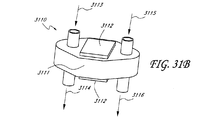
図31Bは、シャント3111と、電極3112と、流入流体ポート3113、3114および流出流体ポート3115、3116とを備えた熱伝達シャント・アセンブリ3110を示す。熱伝達シャント・アセンブリ3110は、図29に示されるシステムより、TE素子当たりの熱伝達力を増大させることができ、より多くの流体輸送能力を有することができる。
FIG. 31B shows a heat
図31Cは、シャント部材3121と、電極3122と、熱交換面3123、3124とを有するシャント・アセンブリ3120を示す。シャント・アセンブリ3120は、図26Aおよび図26Bに示される実施形態に比べて、TE素子当たり約2倍の熱伝達力を有することができる。しかし、図26Aおよび図26Bに示される用途とは対照的に、シャント・アセンブリ3120のスタックは、互いに対して略直角で交互に配置され、互いに対向する面3123、3124はいずれもたとえば加熱され、加熱された対に対して略直角であるスタックの次の対の面が冷却される。あるいは、面3123、3214は、120°などの他の角度であってもよく、図26に示されるようにシャント2604と相互に点在してもよい。多面シャントの任意の組み合わせは、本発明の一部である。
FIG. 31C shows a
熱電材料の削減は相当劇的でありうることに留意すべきである。たとえば、本明細書で説明した熱電素子は、1つの一般的な実施形態では5ミクロン〜1.2mm程度に薄くてもよい。図31A〜図31C、図26A〜図26Bおよび図27の実施形態を用いて実現可能であるような超格子構成およびヘテロ構造構成の場合には、熱電素子は20ミクロン〜300ミクロンの厚さであってもよく、20ミクロン〜200ミクロンであればさらに好ましく、20ミクロン〜100ミクロンではさらに一層好ましい。別の実施形態において、熱電素子の厚さは、100ミクロン〜600ミクロンである。熱電素子に関するこれらの厚さは、従来の熱電システムより実質的に薄い。 It should be noted that the reduction of thermoelectric materials can be quite dramatic. For example, the thermoelectric elements described herein may be as thin as 5 microns to 1.2 mm in one general embodiment. In the case of superlattice and heterostructure configurations, such as can be realized using the embodiments of FIGS. 31A-31C, 26A-26B, and 27, the thermoelectric element is 20 microns to 300 microns thick. It may be 20 to 200 microns, more preferably 20 to 100 microns, and even more preferably 20 to 100 microns. In another embodiment, the thickness of the thermoelectric element is between 100 microns and 600 microns. These thicknesses for thermoelectric elements are substantially thinner than conventional thermoelectric systems.
記載した構成はTE素子をアレイまたはモジュールに組み立てる必要はないことに留意すべきである。一部の用途では、TE素子は、熱伝達部材に直接取り付けることが有利であり、それによりシステムの複雑さおよびコストが削減される。上記の特徴は、本発明を逸脱することなく好都合な態様で組み合わせてもよいことも留意すべきである。さらに、TE素子が類似のサイズであるかのようにさまざまな図面で示されているが、TE素子はアレイまたはスタックにわたってサイズが変化してもよく、最終的なTE素子タイプはP型TE素子とは異なるサイズおよび形状であってもよく、いくつかのTE素子はヘテロ構造であり、他のTE素子は非ヘテロ構造に設計されてもよいことに留意すべきである。 It should be noted that the described arrangement does not require the TE elements to be assembled into an array or module. In some applications, it is advantageous to attach the TE element directly to the heat transfer member, thereby reducing system complexity and cost. It should also be noted that the features described above may be combined in any convenient manner without departing from the invention. Further, although the TE elements are shown in various drawings as if they were of similar size, the TE elements may vary in size across the array or stack, and the final TE element type is a P-type TE element It should be noted that some TE elements may be heterostructures, and some TE elements may be designed as non-heterostructures.
一般に、これらの図面に記載されたシステムは、冷却/加熱モードおよび発電モードの両方で動作する。冷却、加熱または発電のための性能を最適化するために、特定の変更を行うことができることが有利である。当業界では公知であるように、発電において高い効率を達成するために、たとえば、大きな温度差(200〜2000°F)が望ましいのに対し、小さな温度差(10〜60°F)は冷却システムおよび加熱システムの特性である。大きな温度差には、異なる構成材料、可能であれば異なる設計寸法および材料からなるTEモジュールおよびTE素子が必要である。しかし、異なる動作モードに関して基本的概念は依然として同じままである。図5、図8および図9に記載される設計は、簡単かつ簡素に、かつ低コストの設計を作成する可能性を提供することから、発電に好都合である。しかし、上述の設計はすべて、特定の発電用途に関して利点を有することができ、考慮しないわけにはいかない。
熱電発電システム
本明細書に記載される特定の実施形態は、技術水準の材料技術を最適化された熱管理とともに取り入れてなる新規な熱電発電機(TPG)システムを提供する。本明細書に記載される特定の実施形態の数値モデルからの結果が、システムの動作を模擬でき、その設計を促進する。先進の多数パラメータの勾配ベースの最適化技法も、本明細書に記載の特定の実施形態に従って最適なTPGシステムの設計に向かって前進するために、種々の設計変数およびパラメータの間の相互作用をよりよく理解するために使用することができる。
In general, the systems described in these drawings operate in both a cooling / heating mode and a power generation mode. Advantageously, certain changes can be made to optimize performance for cooling, heating or power generation. As is known in the art, to achieve high efficiency in power generation, for example, a large temperature difference (200-2000 ° F.) is desirable, whereas a small temperature difference (10-60 ° F.) is a cooling system. And the characteristics of the heating system. Large temperature differences require TE components and TE elements of different construction materials, possibly different design dimensions and materials. However, the basic concept remains the same for the different modes of operation. The designs described in FIGS. 5, 8 and 9 are advantageous for power generation because they offer the possibility of creating a simple, simple and low cost design. However, all of the above designs can have advantages for specific power generation applications and cannot be ignored.
Thermoelectric Power Generation System Certain embodiments described herein provide a novel thermoelectric generator (TPG) system that incorporates state of the art material technology with optimized thermal management. Results from the numerical models of certain embodiments described herein can simulate the operation of the system and facilitate its design. Advanced multi-parameter gradient-based optimization techniques also allow interaction between various design variables and parameters to advance toward the design of an optimal TPG system in accordance with the specific embodiments described herein. Can be used for better understanding.
本明細書に記載の特定の実施形態においては、システムが、セグメント型一連の熱電(TE)素子(例えば、それぞれのTE素子が最大3つの異なる材料を含む)を備える。特定の実施形態は、好都合には、作動流体の流れの方向の熱絶縁を、熱伝達装置へと直接的に統合された高い出力密度のTE材料に組み合わせる。電流が、特定の実施形態においては熱源およびシンクの表面に平行に流れ、TE材料の多数の幾何学的自由度への統合を好都合に可能にする。この設計の属性が熱絶縁の熱力学的サイクルに組み合わせられる特定の実施形態においては、システムが、システムのそれぞれのTE素子を半独立に最適化することを好都合に可能にする。特定の実施形態においては、P型およびN型のTE素子のそれぞれが、それぞれのTE素子のTE材料層が動作時にTE層へと加わる温度範囲において充分に高い(例えば、可能な限り最高であり、あるいは所望の効率をもたらすために充分に高い)性能指数(ZT)の値を有するように選択されるさまざまなアスペクト比を有することができる。本明細書に記載される特定の実施形態の高い設計の柔軟性は、通常は性能を低下させるセグメント型TE素子および流体の流れに関係するTE材料の適合性の問題に対処するうえで、好都合に役に立つ。さらに、熱膨張の不一致の影響を除去しつつ、優秀な熱的および電気的接触を依然として維持することが、本明細書に記載の特定の実施形態によって好都合に達成される。さらに、電気および熱コネクタの設計ならびに界面の抵抗の最小化など、さらなる設計上の考慮事項が、TEシステムの設計を最適化するために、本明細書に記載の特定の実施形態において選択される。特定の実施形態のシステムは、排熱の回収および電源の両方の用途に適している。 In certain embodiments described herein, the system comprises a segmented series of thermoelectric (TE) elements (eg, each TE element includes up to three different materials). Certain embodiments advantageously combine thermal insulation in the direction of working fluid flow with a high power density TE material integrated directly into the heat transfer device. The current flows parallel to the surface of the heat source and sink in certain embodiments, advantageously allowing integration of the TE material into multiple geometrical degrees of freedom. In certain embodiments where this design attribute is combined with a thermodynamic cycle of thermal isolation, the system advantageously allows for semi-independent optimization of each TE element of the system. In certain embodiments, each of the P-type and N-type TE elements is sufficiently high in the temperature range in which the TE material layer of the respective TE element is applied to the TE layer during operation (eg, the highest possible). Or a variety of aspect ratios selected to have a figure of merit (ZT) value that is high enough to provide the desired efficiency. The high design flexibility of certain embodiments described herein is advantageous in addressing the TE material compatibility issues associated with segmented TE elements and fluid flow, which usually degrade performance. Useful for. Moreover, it is advantageously achieved by certain embodiments described herein that excellent thermal and electrical contact is still maintained while eliminating the effects of thermal expansion mismatch. Further, additional design considerations, such as electrical and thermal connector design and interface resistance minimization, are selected in certain embodiments described herein to optimize TE system design. . Certain embodiments of the system are suitable for both waste heat recovery and power supply applications.
発電のために熱電気を有用に使用する可能性は、近年において大幅に高まっている。1よりも大幅に大きい性能指数(ZT)を有する新規なより高温の材料の進歩が、Michigan State University(例えば、K.F.Hsuらの「Cubic AgPbmSbTe2+m:Bulk Thermoelectric Materials with High Figure of Merit」、Science、第303巻、2004年2月6日、818−821頁を参照)およびMassachusetts Institute of Technology(MIT)のLincoln Laboratory(例えば、T.C.Harmanらの「Quantum Dot Superlattice Thermoelectric Materials and Devices」、Science、第297巻(2002年)、2229−2232頁を参照)などの場所で開発中である。さらに、Jet Propulsion Laboratory(JPL)が、材料のセグメント化の考え方の開発において大きな成功を収めている(例えば、T.Caillatらの「Development of High Efficiency Segmented Thermoelectric Unicouples」、20th Int’l Conf. on Thermoelectrics、Beijing、China、2001年、282−285頁を参照)。 The potential for the useful use of thermoelectricity for power generation has increased significantly in recent years. Advances in new higher temperature materials with a figure of merit (ZT) significantly greater than 1 have been reported by Michigan State University (eg, KF Hsu et al., “Cubic AgPb m SbTe 2 + m : Bulk Thermoelectric Material Hf). Merit, Science, 303, Feb. 6, 2004, pp. 818-821) and Massachusetts Institute of Technology (MIT) Lincoln Laboratory Quantum Quantum Quantum Quantum Quantum Quantum and Devices ", Science, 29th. Winding (2002), pp. 2229-2232) is being developed in places such as. In addition, Jet Propulsion Laboratory (JPL) has had great success in developing material segmentation concepts (see, for example, T. Caillat et al. “Development of High Efficiency Segmented Thermocouples' 20”. Thermoelectrics, Beijing, China, 2001, pages 282-285).
一方で、BSST, Inc.が、流れの方向における熱絶縁の利益を実証している(例えば、L.E.Bellの「Use of Thermal Isolation to Improve Thermoelectric System Operating Efficiency」、21st Int’l Conf. on Thermoelectrics、Long Beach、California、2002年、477−487頁、およびR.W.Dillerらの「Experimental Results Confirming Improved Performance of Systems Using Thermal Isolation」、21st Int’l Conf. on Thermoelectrics、Long Beach、California、2002年、548−550頁を参照)。これらの利益は、改善されたHVAC性能係数(COP)、ならびに従来のTEベースの発電機設計の約1/6のTE材料の使用しか必要としない高い出力密度の設計を含むことができる(例えば、L.E.Bellの「High Power Density Thermoelectric Systems」、23rd Int’l Conf. on Thermoelectrics、Adelaide、Australia、2004年を参照)。 Meanwhile, BSST, Inc. Have demonstrated the benefits of thermal insulation in the direction of flow (see, for example, LE Bell's “Use of Thermal Isolation to Improve Thermal System Operating Efficiency”, 21st Int'l Conf. 2002, 477-487, and RW Diller et al., "Experimental Results Configuring Improving Performance of Systems Using Thermal Con, El. , California, 2002 years, pp. 548-550). These benefits can include improved HVAC performance factor (COP), as well as high power density designs that only require the use of about 1/6 TE material of conventional TE-based generator designs (eg, L. E. Bell, "High Power Density Thermoelectric Systems", 23rd Int'l Conf. On Thermoelectrics, Adelaide, Australia, 2004).
本明細書に記載の特定の実施形態は、これらの発展を踏まえており、熱電気を使用して熱源から抽出できる電力の量をさらに増すために、さらなる設計の革新を利用する。特定の実施形態は、高い出力密度の考え方に好都合に組み合わせられる(例えば、L.E.Bellの「Alternate Thermoelectric Thermodynamic Cycles with Improved Power Generation Efficiencies」、22nd Int’l Conf on Thermoelectrics、Herault、France、2003年を参照)。 The particular embodiments described herein are based on these developments and take advantage of further design innovations to further increase the amount of power that can be extracted from the heat source using thermoelectricity. Certain embodiments are advantageously combined with the idea of high power density (see, eg, LE Thermoelectric Thermodynamic Cycle with Improved Power Generation Efficiencies, 22nd Int'l'Cont. See year).
図32は、本明細書に開示の特定の実施形態による典型的な熱電システム3200の一部分を概略的に示している。特定の実施形態においては、図32によって概略的に示されている構成が、さらに詳しく後述されるとおり、さまざまな利益を好都合にもたらす。特定の実施形態においては、図32によって概略的に示される構成が、種々の厚さ、面積、および熱膨張係数のTE素子により容易に対応する。さらに、この構成は、高い出力密度の材料、高い出力密度の動作をもたらすように寸法付け螺得たTE素子、およびの作動流体の流れの方向における熱絶縁の使用にも対応する。
FIG. 32 schematically illustrates a portion of an exemplary
熱電システム3200は、互いに電気的に連絡した第1の複数のセグメント3212を備える第1の熱電素子3210を備える。さらに、熱電システム3200は、互いに電気的に連絡した第2の複数のセグメント3222を備える第2の熱電素子3220を備える。さらに、熱電システム3200は、少なくとも第1の部位3232および第2の部位3234を備える熱伝達装置3230を備える。第1の部位3232が、第1の熱電素子3210と第2の熱電素子3220との間に挟まれている。第2の部位3234は、第1の部位3232から離れるように突き出しており、作動媒体(図示されていない)に熱的に連絡するように構成されている。
The
特定の実施形態においては、第1の複数のセグメント3212のうちの少なくともいくつかが、互いに直列に電気的に連絡し、第2の複数のセグメント3222のうちの少なくともいくつかが、互いに直列に電気的に連絡する。特定の実施形態においては、第1の複数のセグメント3212のうちの少なくともいくつかが、互いに直列/並列に電気的に連絡し、第2の複数のセグメント3222のうちの少なくともいくつかが、互いに直列/並列に電気的に連絡する。
In certain embodiments, at least some of the first plurality of
図32は、3つの熱伝達装置3230を第1のTE素子3210および第2のTE素子3220によって隔てて備える例としてのスタックを概略的に示している。いくつかの別の実施形態は、複数のTE素子(交互のP型およびN型のTE素子)および熱伝達装置を備える少なくとも1つのスタックを備えており、熱伝達装置が、複数のTE素子のうちの少なくとも2つのTE素子の間に挟まれている。
FIG. 32 schematically illustrates an example stack comprising three
特定の実施形態の熱伝達装置3230は、第1のTE素子3210から第2のTE素子3220への電気的経路をもたらして、電流源からの電流が第1のTE素子3210、熱伝達装置3230、および第2のTE素子3220を直列に横切るように、TEのp−n対を完成させている。そのような特定の実施形態においては、電流が、第1の複数のセグメント3212を直列に横切り、第2の複数のセグメント3222を直列に横切る。
The
さらに、特定の実施形態の熱伝達装置3230は、作動流体からTE素子3210、3220への熱の経路をもたらす。図32によって概略的に示されている構成においては、電流が熱源およびシンクの表面に平行に流れるため、TE材料を多数の幾何学的自由度に融合させることができる。特定の実施形態においては、熱伝達装置3230が、TE素子のうちの少なくともいくつかを、TE素子のうちの少なくとも別のいくつかから熱的に絶縁する。特定の実施形態においては、複数の熱伝達装置3230が、作動媒体の流れの方向に熱絶縁をもたらすように配置される。
Further, the
特定の実施形態においては、熱伝達装置3230の第2の部位3234が、少なくとも1つの方向(例えば、作動媒体の移動方向におおむね沿った方向)において、熱伝達装置3230の第1の部位3232よりも幅広い。特定の実施形態においては、第2の部位3234が、作動媒体に熱的に連絡するように構成されたおおむね平坦な表面である。
In certain embodiments, the
特定の実施形態においては、スタックが、複数の第1の熱伝達装置および複数の第2の熱伝達装置を備えており、第1および第2の熱伝達装置が、スタックに沿って交互に位置している。第1の熱伝達装置が、第1の方向に突き出しており、第2の熱伝達装置が、第1の方向とは異なる第2の方向に突き出している。第2の方向は、特定の実施形態においては、図32によって概略的に示されているとおり第1の方向とおおむね反対である。特定の実施形態においては、第1の熱伝達装置が、第1の作動媒体(例えば、流れている第1の作動流体)に熱的に連絡するように構成され、第2の熱伝達装置が、第12の作動媒体(例えば、流れている第2の作動流体)に熱的に連絡するように構成されている。 In certain embodiments, the stack comprises a plurality of first heat transfer devices and a plurality of second heat transfer devices, wherein the first and second heat transfer devices are located alternately along the stack. is doing. The first heat transfer device protrudes in the first direction, and the second heat transfer device protrudes in a second direction different from the first direction. The second direction, in certain embodiments, is generally opposite to the first direction as schematically illustrated by FIG. In certain embodiments, the first heat transfer device is configured to be in thermal communication with a first working medium (eg, a flowing first working fluid), and the second heat transfer device is , Configured to be in thermal communication with a twelfth working medium (eg, a flowing second working fluid).
特定の実施形態においては、第1の部位3232と第1の部位3232から離れるように突き出している第2の部位3234とを有している熱伝達装置3230が、矩形の形状の熱伝達装置を超える1つ以上の利益をもたらす。熱伝達装置3230の電気抵抗および重量を小さくするため、第1の部位3232の電流の流れの方向の厚さを、好都合に最小化することができる。さらに、電流の流れの方向におおむね垂直な平面における第1の部位3232の寸法を、TE素子3210、3220への充分な電気および熱伝導をもたらすように、好都合に最適化することができる。作動流体の流れの方向に沿った第2の部位3234の表面積および/または厚さを、熱源またはヒートシンクと熱伝達装置3230の第1の部位3232との間により大きな熱の通路をもたらして熱抵抗が大きくならないようにするために、好都合に増すことができる。また、第2の部位3234が、スタックにおおむね沿う方向において幅広く、スタックにおおむね垂直な方向において短いことも、好都合である。第2の部位3234をスタックにおおむね垂直な方向において短く保つことは、熱源またはヒートシンクからTE素子の表面への熱抵抗を好都合に小さくする。重量、構造的な安定性、TEの表面積、および界面における温度勾配を、それぞれ、熱伝達装置3230の最終寸法の設計において考慮することができる。
In certain embodiments, a
特定の実施形態においては、第1の複数のセグメント3212が、2つ、3つ、または4つ以上の異なる熱電材料を含む。特定の実施形態においては、第2の複数のセグメント3222が、2つ、3つ、または4つ以上の異なる熱電材料を含む。例えば、図32に示されているように、第1の複数のセグメント3212が、異なるTE材料(例えば、それぞれp−CeFe3RuSb12、p−TAGS、およびp−Bi2Te3)からなる3つのP型セグメント3212a、3212b、3212cを有し、第2の複数のセグメント3222が、3つのN型セグメント3222a、3222b、3222cを有する(例えば、それぞれn−CoSb3、n−PbTe、およびn−Bi2Te3)。図32においては、第1のTE素子3210が、高温端が左側である水平方向の温度勾配に曝され、第2のTE素子3220が、高温端が右側である水平方向の温度勾配に曝される。さらに詳しく後述されるとおり、TE材料をセグメントに分けることによって、特定の実施形態のTE素子を、TE素子全体のうちのそれぞれのTE素子の材料の特性をTE素子全体にわたる動作温度勾配または温度プロファイルに一致させることによって、TE素子について意図される動作温度範囲にわたってより高い平均ZTをより良好に達成するように、設計することができる。
In certain embodiments, the first plurality of
TE素子のエネルギー変換効率は、一般に、TE素子の平均の無次元の性能指数ZTが増すにつれて、大きく向上する。図33Aおよび33Bが、本明細書に記載の特定の実施形態に適合する種々のP型およびN型の熱電材料のそれぞれについて、性能指数(ZT)を温度の関数として示している。材料は、所与の温度における材料の性能の効率を決定する1つ以上の熱電特性の組を有することができ、性能指数は、1つ以上の熱電特性の組の特徴を示す典型的なパラメータである。 In general, the energy conversion efficiency of a TE element greatly improves as the average dimensionless figure of merit ZT of the TE element increases. Figures 33A and 33B show a figure of merit (ZT) as a function of temperature for each of the various P-type and N-type thermoelectric materials compatible with the particular embodiments described herein. A material can have one or more thermoelectric property sets that determine the efficiency of the material's performance at a given temperature, and the figure of merit is a typical parameter that is characteristic of one or more thermoelectric property sets. It is.
例えば、低い温度(例えば、150℃未満)においては、Bi2Te3が、P型およびN型の両方のTE材料について最も高いZTを有している。中間的な温度(例えば、150〜500℃)においては、TAGSが最適なP型材料であり、Zn4Sb3が、このおおよその温度範囲におけるもう1つの選択肢である。PbTeが、N型材料について、この同じおおよその温度範囲において高いZTを有している。より高い温度範囲(例えば、500〜700℃)においては、スクッテルド鉱(例えば、p−CeFe4SB12、n−CoSb3)が、高いZTを有している。本明細書に記載される特定の実施形態は、材料および/または材料の組み合わせが使用の温度範囲にわたって充分に高い(例えば、可能な限り最高、あるいは所望の効率をもたらすために充分に高い)平均ZTをもたらしているTE素子を使用する。 For example, at low temperatures (eg, below 150 ° C.) Bi 2 Te 3 has the highest ZT for both P-type and N-type TE materials. At intermediate temperatures (eg, 150-500 ° C.), TAGS is the optimal P-type material, and Zn 4 Sb 3 is another option in this approximate temperature range. PbTe has a high ZT in this same approximate temperature range for N-type materials. In higher temperature ranges (eg 500-700 ° C.), skutterudites (eg p-CeFe 4 SB 12 , n-CoSb 3 ) have a high ZT. Certain embodiments described herein provide an average of materials and / or combinations of materials that are sufficiently high over the temperature range of use (eg, as high as possible or high enough to provide the desired efficiency). Use a TE element that provides ZT.
TE材料の特性の例として、図34が、ヨウ素で種々のレベルにドープされた3つの異なる組成のテルル化鉛(M1、M2、およびM3で指し示されている)について、性能指数ZTを温度の関数として示している。図34は、1つの材料が100℃〜570℃の温度の範囲の全体にわたって最高のZTを有するわけではないことを示している。組成M1が、約100℃〜約335℃の温度において最高のZTを有し、組成M2が、約335℃〜約455℃の温度において最高のZTを有し、組成M3が、約455℃〜約570℃の温度において最高のZTを有している。TE素子が100℃〜570℃にわたっていずれか1つの組成で製造される場合、平均のZTは、3つの組成のすべてから製造され、各組成またはTEセグメントが当該組成またはTEセグメントが3つの組成のうちの最高のZTを有する範囲の温度に曝されるように適切に構成されている素子の平均のZTに比べ、大幅に低くなるであろう。図34は、ヨウ素でドープされたテルル化鉛の種々の組成に対応しているが、他のTE材料およびドーパントも、本明細書に記載される種々の実施形態に適合する(例えば、図33Aおよび33Bを参照)。 As an example of the properties of TE materials, FIG. 34 shows the figure of merit for three different compositions of lead telluride doped with various levels of iodine (indicated by M 1 , M 2 , and M 3 ). ZT is shown as a function of temperature. FIG. 34 shows that one material does not have the highest ZT over the entire temperature range of 100 ° C. to 570 ° C. Composition M 1 has the highest ZT at a temperature of about 100 ° C. to about 335 ° C., Composition M 2 has the highest ZT at a temperature of about 335 ° C. to about 455 ° C., and Composition M 3 is about It has the highest ZT at temperatures from 455 ° C to about 570 ° C. When a TE element is manufactured in any one composition from 100 ° C. to 570 ° C., the average ZT is manufactured from all three compositions, each composition or TE segment having that composition or TE segment having three compositions. It will be significantly lower than the average ZT of devices that are properly configured to be exposed to temperatures in the range with the highest ZT. Although FIG. 34 corresponds to various compositions of lead telluride doped with iodine, other TE materials and dopants are also compatible with various embodiments described herein (eg, FIG. 33A). And 33B).
特定の実施形態においては、第1および第2のTE素子3210、3220のうちの一方が、P型のTE素子からなり、第1および第2のTE素子3210、3220のうちの他方が、N型のTE素子からなる。そのような特定の実施形態においては、第1および第2のTE素子3210、3220のセグメントの異なるP型およびN型のTE材料が、第1および第2のTE素子3210、3220のセグメントの意図される動作温度範囲にわたって、充分に高い(例えば、可能な限り最高、あるいは所望の効率をもたらすために充分に高い)平均ZTをもたらすように選択される。
In a particular embodiment, one of the first and
例えば、第1の複数のセグメント3212が、異なる材料からなる少なくとも第1のTEセグメントおよび第2のTEセグメントを含む。熱電システム3200を、特定の実施形態においては、第1のTEセグメントが第1の温度範囲に曝され、第2のTEセグメントが第2の温度範囲に曝されるように、動作するように構成することができる。第1のTEセグメントが、第1の温度範囲において第2の温度範囲よりも効率的に動作する。第2のTEセグメントが、第2の温度範囲において第1の温度範囲よりも効率的に動作する。
For example, the first plurality of
図32のシステム3200を参照すると、特定の実施形態においては、第1のTE素子3210が、異なる材料からなる3つのTEセグメント3212a、3212b、3212cを備える。システム3200が、第1のTEセグメント3212aが第1の温度範囲に曝され、第2のTEセグメント3212bが第2の温度範囲に曝され、第3のTEセグメント3212cが第3の温度範囲に曝されるように、動作するように構成される。第1のTEセグメント3212aが、第1の温度範囲において、第2または第3の温度範囲よりも効率的に動作する。第2のTEセグメント3212bが、第2の温度範囲において、第1または第3の温度範囲よりも効率的に動作する。第3のTEセグメント3212cが、第3の温度範囲において、第2または第3の温度範囲よりも効率的に動作する。
Referring to the
同様に、特定の実施形態においては、第2の複数のセグメント3222が、第1の温度範囲に曝される第1のTEセグメントおよび第2の温度範囲に曝される第2のTEセグメントを少なくとも含んでおり、第1および第2のTEセグメントは、異なる材料からなっている。第1のTEセグメントが、第1の温度範囲において第2の温度範囲よりも効率的に動作する。第2のTEセグメントが、第2の温度範囲において第1の温度範囲よりも効率的に動作する。図32を参照すると、特定の実施形態において、第2のTE素子3220は、異なる材料からなる3つのTEセグメント3222a、3222b、3222cを備えており、第1のTEセグメント3222aが第1の温度範囲に曝され、第2のTEセグメント3222bが第2の温度範囲に曝され、第3のTEセグメント3222cが第3の温度範囲に曝されるように、動作するように構成されている。第1のTEセグメント3222aが、第1の温度範囲において、第2または第3の温度範囲よりも効率的に動作する。第2のTEセグメント3222bが、第2の温度範囲において、第1または第3の温度範囲よりも効率的に動作する。第3のTEセグメント3222cが、第3の温度範囲において、第2または第3の温度範囲よりも効率的に動作する。
Similarly, in certain embodiments, the second plurality of
特定の実施形態においては、これらに限られるわけではないが熱的安定性、機械的安定性、およびコストなどといったさまざまな他の因子も、動作温度の関数として使用すべきTE材料を選択する際に、考慮することができる。さらに詳しく後述されるとおり、本明細書に記載の特定の実施形態に適合できるTE素子の設計における他の因子は、個々の素子セグメントが大きく異なる電流密度において効果的に機能する場合に、適合性不一致が最適な出力にもたらす影響である(例えば、J.G.Snyderの「Thermoelectric Power Generation:Efficiency and Compatibility」、Thermoelectrics Handbook、Macro to Nano、D.M.Rowe,pH.D.,D.Sc編(2006年)を参照)。 In certain embodiments, various other factors such as, but not limited to, thermal stability, mechanical stability, and cost may also be used in selecting the TE material to be used as a function of operating temperature. Can be considered. As will be described in more detail below, other factors in the design of TE elements that can be adapted to the specific embodiments described herein are conformity when individual element segments function effectively at very different current densities. The mismatch is the effect on optimal output (see, eg, JG Snyder's “Thermoelectric Power Generation: Efficiency and Compatibility”, Thermoelectrics Handbook, Macro to Nano, D. M. D. M. D. M. D. M. D. Ed. (2006)).
TE材料の出力曲線は、電流が増すにつれておおむね放物線である。異なるTE材料が一緒に使用されているセグメント型TE素子においては、TE素子および/またはセグメントの出力曲線が、大きく異なる電流密度にて最適な出力の発生を有する可能性がある。出力曲線におけるこれらの相違が、セグメント型TE素子の全体としての効率を下げてしまう可能性がある。 The output curve of TE material is generally parabolic as the current increases. In segmented TE elements in which different TE materials are used together, the TE element and / or segment output curves may have optimal power generation at very different current densities. These differences in the output curve can reduce the overall efficiency of the segmented TE element.
それぞれのTE素子の温度が相違する(例えば、一連のTE素子が作動流体の流れの方向に組み上げられている)特定の実施形態においては、そのような出力曲線の適合性の不一致の影響が大きくなりうる。図25が、高温側の温度Thが700Kから500Kへと低下する場合について、流れの方向に直列に構成された3つのTE素子の間の出力曲線の適合性の不一致を示している。第1のTE素子は、高温側温度Th=700Kに曝され、第2のTE素子は、高温側温度Th=600Kに曝され、第3のTE素子は、高温側温度Th=500Kに曝される。これら3つのTE素子のそれぞれの低温側温度Tcは、この例では300Kで一定のままである。理想的には、それぞれのTE素子が、ピーク出力を生み出す電流にて動作すると考えられる。しかしながら、3つのTE素子は電気的に直列に接続されているため、それぞれ同じ電流を使用して動作する。第1のTE素子が、130Aに最大出力を有する一方で、この電流において、残りの2つのTE素子の出力は最適でない(例えば、それぞれの最大出力よりも小さい)。とくには、500K〜300Kの間で動作している第3の素子は、130Aにおいて出力がゼロである。この例における総ピーク出力は7.69Wであり、個々のTE素子の個々のピーク出力を大きく下回る。他の例では、第3のTE素子の出力が、第1のTE素子の最適電流において負になる可能性があり、第3のTE素子が、他の2つのTE素子からの出力を取り去る可能性がある。 In certain embodiments where the temperature of each TE element is different (e.g., a series of TE elements are assembled in the direction of working fluid flow), the impact of such power curve compatibility mismatch is significant. Can be. Figure 25 is a case where the temperature T h of the high-temperature side is decreased to 500K from 700K, shows a mismatch compatible output curve between the three TE elements configured in series in the direction of flow. The first TE element is exposed to a high temperature side temperature T h = 700K, the second TE element is exposed to a high temperature side temperature T h = 600K, and the third TE element is exposed to a high temperature side temperature T h = 500K. Exposed to. The low temperature Tc of each of these three TE elements remains constant at 300K in this example. Ideally, each TE element would operate at a current that produces a peak output. However, since the three TE elements are electrically connected in series, each operates using the same current. While the first TE element has a maximum output at 130 A, at this current the output of the remaining two TE elements is not optimal (eg, less than the respective maximum output). In particular, the third element operating between 500K and 300K has zero output at 130A. The total peak power in this example is 7.69 W, well below the individual peak power of the individual TE elements. In another example, the output of the third TE element can be negative at the optimum current of the first TE element, and the third TE element can remove the output from the other two TE elements. There is sex.
特定の実施形態においては、TE素子のフォームファクタまたは形状が、それぞれのTE素子がピーク出力またはピーク効率をもたらす電流にて動作することによって出力がもたらされるように、好都合に選択される。そのような特定の実施形態においては、TE素子のアスペクト比が、流れの方向において変化させられることで、TE素子間のTE適合性の不一致の影響を好都合に小さくする。例えば、図32を参照すると、特定の実施形態において、第1のTE素子3210が、第1の方向(例えば、第1のTE素子3210を通過する電流の流れの方向)に沿って第1の厚さを有し、第1の方向におおむね垂直な平面において第1の断面積を有する。第2のTE素子3220は、第2の方向(例えば、第2のTE素子3220を通過する電流の流れの方向)に沿って第2の厚さを有し、第2の方向におおむね垂直な平面において第2の断面積を有する。特定の実施形態においては、第2の厚さが第1の厚さよりも大きい。他の特定の実施形態においては、第1のTE素子3210が、第1の断面積の第1の厚さでの割り算に等しい第1のアスペクト比を有し、第2のTE素子3220が、第2の断面積の第2の厚さでの割り算に等しい第2のアスペクト比を有する。そのような特定の実施形態において、第2のアスペクト比が、第1のアスペクト比と相違する。例えば、第1のアスペクト比および第2のアスペクト比を、動作状態のもとで第1のTE素子3210および第2のTE素子3220の両者が最適効率で動作するように選択することができる。
In certain embodiments, the form factor or shape of the TE elements is advantageously selected such that the output is provided by operating each TE element at a current that provides peak power or peak efficiency. In such a specific embodiment, the aspect ratio of the TE elements can be varied in the direction of flow to advantageously reduce the effects of TE compatibility mismatch between the TE elements. For example, referring to FIG. 32, in a particular embodiment, the
図36は、本明細書に記載の特定の実施形態による典型的な装置について、異なるアスペクト比を有する3つのTE素子の間の出力曲線を示している。図35と同様、図36の3つのTE素子は、流れの方向に直列に構成され、3つのTE素子の高温側の温度Thは、それぞれ700K、600K、および500Kであり、それぞれのTE素子の低温側の温度Tcは、300Kである。図35の3つのTE素子のそれぞれは、1mmの厚さを有している。図36においては、第1のTE素子が、1mmの厚さを有し、第2のTE素子が、0.77mmの厚さを有し、第3のTE素子が、0.5mmの厚さを有している。図36によって示されるように、直列である第2および第3のTE素子のアスペクト比を変更することで、TE素子がそれぞれの最大出力を達成する電流が好都合に一致し、装置の全体の出力密度が向上する。図36の例の装置の総ピーク出力は、11.51Wであり、図35の例の装置の出力に対する50%の改善である。 FIG. 36 shows the output curve between three TE elements with different aspect ratios for an exemplary device according to certain embodiments described herein. Similar to FIG. 35, three TE elements of Figure 36 is constructed in the direction of flow in series, the temperature T h of the high-temperature side of the three TE elements are each 700K, 600 K, and 500K, respectively TE element The temperature Tc on the low temperature side is 300K. Each of the three TE elements in FIG. 35 has a thickness of 1 mm. In FIG. 36, the first TE element has a thickness of 1 mm, the second TE element has a thickness of 0.77 mm, and the third TE element has a thickness of 0.5 mm. have. As shown by FIG. 36, changing the aspect ratio of the second and third TE elements in series advantageously matches the current at which the TE element achieves its respective maximum output, resulting in an overall output of the device. The density is improved. The total peak power of the example device of FIG. 36 is 11.51 W, a 50% improvement over the output of the example device of FIG.
図37は、従来からの構成3700における1対のセグメント型TE素子を概略的に示している。従来からの構成3700は、第1のTEセグメント型TE素子3710および第2のTE素子3720を有している。第1および第2のTE素子3710、3720の各々が、導電性かつ熱伝導性のカプラ3730の片面へと接続されている。第1のTE素子3710は、3つのP型セグメント3712a、3712b、3712c(例えば、それぞれp−CeFe3RuSb12、p−TAGS、およびp−Bi2Te3)を有しており、第2のTE素子3720は、3つのN型セグメント3722a、3722b、3722c(例えば、それぞれn−CoSb3、n−PbTe、n−Bi2Te3)を有している。図37においては、温度勾配は、縦方向であって高温端が上である。
FIG. 37 schematically shows a pair of segmented TE elements in a conventional configuration 3700. A conventional configuration 3700 includes a first TE segment
図37に概略的に示されているように、従来からのTE構成においては、TE素子3710、3720が、それぞれのTE素子3710、3720が電流の方向において同じ厚さを有するようにTEモジュールへと一体化されている。このような従来からのTE構成3700においては、異なる厚さ、面積、またはアスペクト比を有するTE素子を使用することが、容易ではない。さらに、このような従来からのTE構成3700は、TE素子が同じ厚さであるがTE素子を通過する電流の方向におおむね平行な方向において異なる熱膨張係数を有している場合に、制御が困難である。このような熱膨張の不整合は、動作温度がきわめて高くなる可能性がある発電システムにおいて、とくに問題となりうる。対照的に、熱伝達装置3230が2つのTE素子3210、3220の間に挟まれている本明細書に記載される特定の実施形態(例えば、図32によって概略的に示されている構成)においては、好都合なことに、異なる厚さ、面積、および/またはアスペクト比のTE素子が容易にシステムに取り入れられる。さらに、このような構成は、TE素子間の熱膨張係数の相違に関連する問題を好都合に軽減または回避する。
As schematically shown in FIG. 37, in a conventional TE configuration,
TE素子の各セグメントの温度が互いに相違する特定の実施形態(例えば、熱源とヒートシンクとの間にTE素子を有している)においては、セグメント間の出力曲線の適合性の不一致が全体としての出力および/または効率にもたらす影響が、大きくなる可能性がある。特定の実施形態においては、そのようなセグメント間の不適合に、TE素子の各セグメントについて異なるアスペクト比(例えば、断面積を厚さで割り算した値)を好都合に選択することによって、少なくとも部分的に対処することができる。特定の実施形態においては、電流を最適な出力へとより良好に一致させるために、実質的に一様な断面積を保ちつつ各セグメントの厚さを変えることによって、TE素子の個々のセグメントに異なるアスペクト比を持たせる。他の特定の実施形態においては、セグメントのアスペクト比を、セグメント間で断面積が非一様であるセグメント化されたTE素子を製作することによって、最適化することができる。 In certain embodiments in which the temperature of each segment of the TE element is different from one another (eg, having a TE element between the heat source and the heat sink), the mismatch in output curve fit between the segments as a whole The impact on power and / or efficiency can be significant. In certain embodiments, such incompatibility between segments is at least in part by advantageously selecting a different aspect ratio (eg, cross-sectional area divided by thickness) for each segment of the TE element. Can be dealt with. In certain embodiments, in order to better match the current to the optimal output, each segment of the TE element can be changed by varying the thickness of each segment while maintaining a substantially uniform cross-sectional area. Have different aspect ratios. In other particular embodiments, the aspect ratio of the segments can be optimized by fabricating segmented TE elements that have non-uniform cross-sectional areas between segments.
例えば、図32の典型的なシステム3200を参照すると、特定の実施形態においては、第1の複数のセグメント3212の各セグメントについて、第1のTE素子3210を通過する電流の流れの方向に沿った厚さが、第1の複数のセグメント3212のうちの残りのセグメントの厚さとは異なる。そのような特定の実施形態において、第2の複数のセグメント3222の各セグメントに関して、第2のTE素子3220を通過する電流の流れの方向に沿った厚さが、第2の複数のセグメント3222のうちの残りのセグメントの厚さとは異なる。特定の実施形態においては、第1の複数のセグメント3212の各セグメントが、或るアスペクト比(セグメントの厚さをセグメントの断面積で割り算した値に等しい)を有しており、第1の複数のセグメント3212の各セグメントのアスペクト比が、互いに相違している。そのような特定の実施形態においては、第2の複数のセグメント3222の各セグメントが、或るアスペクト比(セグメントの厚さをセグメントの断面積で割り算した値に等しい)を有しており、第2の複数のセグメント3222の各セグメントのアスペクト比が、互いに相違している。第1の複数のセグメント3212の各セグメントのアスペクト比および第2の複数のセグメント3222の各セグメントのアスペクト比は、特定の実施形態においては、動作状態のもとで第1の熱電素子3210および第2の熱電素子3220の両方が最適効率で動作するように選択される。
For example, referring to the
図38が、モデル計算を使用して模擬された3つの異なる構成の平均効率を示している。モデルは、3つのTE素子および2つの熱伝達装置からなるスタックであって、本明細書に記載の特定の実施形態に従って熱伝達装置が作動流体の流れの方向においてTE素子を互いに熱的に絶縁しているスタックについて、3つの異なる構成の性能を模擬している。TE素子の高温側の温度が、700℃から300℃へと変化する一方で、TE素子の低温側の温度は、100℃から150℃へと変化し、したがって3つのTE素子を横切る温度差は、それぞれ550℃、375℃、および200℃であった。 FIG. 38 shows the average efficiencies of three different configurations that were simulated using model calculations. The model is a stack of three TE elements and two heat transfer devices, where the heat transfer devices thermally insulate the TE elements from each other in the direction of the working fluid flow according to the specific embodiment described herein. For the stack we are simulating the performance of three different configurations. While the temperature on the high temperature side of the TE element changes from 700 ° C. to 300 ° C., the temperature on the low temperature side of the TE element changes from 100 ° C. to 150 ° C. Therefore, the temperature difference across the three TE elements is , 550 ° C., 375 ° C., and 200 ° C., respectively.
第1の構成(図38において「セグメント化無し、アスペクト比一様」と記されている)においては、3つのTE素子のすべてが、ただ1つの材料から製作されており(セグメント化無し)、それぞれのTE素子の材料が、他のTE素子の材料と同じであり(2つがN型となるようにドープされ、1つがP型となるようにドープされている)、それぞれのTE素子が、同じアスペクト比を有している。第2の構成(図38において「一様なセグメント化およびアスペクト比」と記されている)においては、TE素子が、各TE素子の動作温度範囲において最適なZTをより上手く利用するためにセグメント分けされており、2つのN型のTE素子は、同じ方法でセグメント化され、3つのTE素子のすべてが、同じアスペクト比を有している。第3の構成(図38において「非一様なセグメント化およびアスペクト比」と記されている)においては、2つのN型のTE素子が、それぞれのTE素子の個々の温度範囲に合わせて異なってセグメント化され、各TE素子のアスペクト比が、好都合に変えられている。3つの構成にすべてにおいて、TE素子は、各TE素子を同じ電流が横切るように電気的に直列に接続されている。 In the first configuration (shown as “no segmentation, uniform aspect ratio” in FIG. 38), all three TE elements are made from just one material (no segmentation), The material of each TE element is the same as the material of the other TE elements (two are doped to be N-type and one is doped to be P-type), and each TE element is Have the same aspect ratio. In the second configuration (denoted as “uniform segmentation and aspect ratio” in FIG. 38), the TE elements are segmented to better utilize the optimum ZT in the operating temperature range of each TE element. The two N-type TE elements are segmented in the same way, and all three TE elements have the same aspect ratio. In the third configuration (denoted “non-uniform segmentation and aspect ratio” in FIG. 38), the two N-type TE elements are different for each TE element's individual temperature range. The aspect ratio of each TE element is advantageously changed. In all three configurations, the TE elements are electrically connected in series so that the same current traverses each TE element.
図38は、TE材料の適合性ならびに流れの方向におけるTE素子の適合性ゆえに、第1の構成は第2の構成よりも効率が35%低く、第2の構成は第3の構成よりも効率が15%低いことを示している。これらの差は、流れの方向に沿ってより熱的に絶縁されたTE素子において、さらに劇的になる。図38は、TE素子の非一様なセグメント化を流れの方向におけるアスペクト比の最適化に組み合わせる本明細書に記載の特定の実施形態によってもたらされる利点を説明している。 FIG. 38 shows that the first configuration is 35% less efficient than the second configuration and the second configuration is more efficient than the third configuration due to the suitability of the TE material as well as the TE element in the direction of flow. Is 15% lower. These differences are even more dramatic in TE elements that are more thermally isolated along the direction of flow. FIG. 38 illustrates the advantages provided by certain embodiments described herein that combine non-uniform segmentation of TE elements with aspect ratio optimization in the direction of flow.
図32によって概略的に示されている構成を利用する特定の実施形態においては、それぞれのTE素子を、他のTE素子から或る程度独立して最適化することができる。例えば、それぞれのP型およびN型のTE素子が、各TE素子の各セグメントがそれぞれの特定の温度範囲において充分に高いZTを有するように、異なる断面積および/または厚さを有することができる。 In certain embodiments utilizing the configuration schematically illustrated by FIG. 32, each TE element can be optimized to some extent independent of other TE elements. For example, each P-type and N-type TE element can have a different cross-sectional area and / or thickness such that each segment of each TE element has a sufficiently high ZT in its particular temperature range. .
特定の実施形態においては、好都合には、熱膨張の不一致を、高温の発電用途のための熱電システムを組み立てるべく熱伝達装置およびTE素子を接合するための材料を選択するときに、考慮に入れることができる。本明細書に記載される特定の実施形態においては、熱電システムの種々の部位の間の熱膨張の不一致に起因する熱応力を少なくとも部分的に緩和するために、剛でない接続を利用する。特定の実施形態においては、剛でない接続が、熱伝達装置とTE素子との間の熱膨張の不一致によって引き起こされる厄介事を、好都合に防止する。さらに、特定の実施形態においては、剛でない接続が、セグメント型TE素子の高温側および低温側の膨脹の不一致を、好都合に保護する。 In certain embodiments, advantageously, thermal expansion mismatch is taken into account when selecting materials for joining heat transfer devices and TE elements to assemble thermoelectric systems for high temperature power generation applications. be able to. In certain embodiments described herein, non-rigid connections are utilized to at least partially relieve thermal stresses due to thermal expansion mismatches between various portions of the thermoelectric system. In certain embodiments, the non-rigid connection advantageously prevents complications caused by thermal expansion mismatch between the heat transfer device and the TE element. Furthermore, in certain embodiments, the non-rigid connection advantageously protects the expansion mismatch between the hot side and the cold side of the segmented TE element.
そのような特定の実施形態においては、熱電システムが、少なくとも1つの剛でないが熱的および電気的に伝導性である接続をもたらすために、少なくとも1つのTE素子と少なくとも1つの隣接の熱伝達装置との間の1つ以上の液体金属ジョイントを備える。例えば、図32によって概略的に示されている熱電システム3200が、第1のTE素子3210および熱伝達装置3230に熱的および電気的に連絡した第1の液体金属ジョイントと、熱伝達装置3230および第2のTE素子3220に熱的および電気的に連絡した第2の液体金属ジョイントとを備えることができる。このジョイントは、室温において液体であっても、システムの動作時にジョイントに加わる温度よりも低い温度で溶けてもよい。例えば、標準的なSnPbはんだを、このはんだの融点をはるかに超える動作温度を有するTE素子の高温側に使用することができる。
In certain such embodiments, the thermoelectric system has at least one TE element and at least one adjacent heat transfer device to provide at least one non-rigid but thermally and electrically conductive connection. One or more liquid metal joints. For example, a
1つ以上の液体金属ジョイントを利用することで、熱電システムの製造にいくつかの厄介事が持ち込まれる可能性がある。特定の実施形態においては、構造的な一体性をもたらすために、追加の構造が使用されるかもしれない。この追加の構造は、好都合には、熱絶縁性であってよい。特定の実施形態においては、少なくとも1つのスタックが、おおむねスタックに沿った圧縮下におかれる。さらに、特定の実施形態においては、液体金属がジョイントから流出して装置を短絡させることがないように、或る程度の制御を好都合に設けることができる。特定の実施形態においては、液体金属が高温に保たれることに起因する界面での早期の腐食または望ましくない合金化(例えば、接合を脆くし、あるいは熱または電気の伝導を小さくする)を防止するために、適切な材料の組み合わせを好都合に使用することができる。 Utilizing one or more liquid metal joints can introduce several challenges to the manufacture of thermoelectric systems. In certain embodiments, additional structures may be used to provide structural integrity. This additional structure may conveniently be thermally insulating. In certain embodiments, at least one stack is placed under compression generally along the stack. In addition, in certain embodiments, some degree of control can be conveniently provided to prevent liquid metal from flowing out of the joint and shorting the device. In certain embodiments, premature corrosion or undesirable alloying at the interface due to the liquid metal being kept at a high temperature (eg, making the joint brittle or reducing thermal or electrical conduction) is prevented. In order to do so, a suitable combination of materials can be advantageously used.
特定の実施形態においては、剛でない接合が、熱伝達装置と熱源またはヒートシンクとの間の界面における熱応力の蓄積を軽減または防止するために、好都合に使用される。熱伝達装置3230の第2の部位3232が、とくには高温側において、熱伝達装置の間のx平面に熱応力の蓄積を生じる可能性がある。熱伝達装置の間のTE材料の熱膨張係数を、熱源の熱膨張係数に一致させることは、困難である可能性がある。したがって、特定の実施形態においては、熱伝達装置が、好都合には液体金属を使用して熱源へと接続される。特定の実施形態においては、この界面における液体金属が、2つの熱伝達装置の間の電気的短絡を生むことがないように拘束される。液体金属を、直近のジョイント領域に好都合に封じ込めることができる。特定の実施形態においては、熱伝達装置が、サーマルグリスを使用してヒートシンク(例えば、400℃未満)へと接合される。特定の実施形態においては、熱電システムが、剛な構造コネクタを使用することなくすべてを所定の位置に保持するために、圧縮下におかれる。この圧縮は、特定の実施形態において、y平面における熱的接触ならびにx平面における熱および電気的接触を向上させることもできる。
In certain embodiments, non-rigid joints are advantageously used to reduce or prevent thermal stress buildup at the interface between the heat transfer device and the heat source or heat sink. The
特定の実施形態においては、モリブデンを、熱伝導性かつ導電性のジョイントをもたらすために使用することができる。例えば、図32によって概略的に示されている熱電システム3200が、第1のTE素子3210と熱伝達装置3230との間のモリブデン層と、熱伝達装置3230と第2のTE素子3220との間のモリブデン層とを備えることができる。モリブデンは、銅の導電性および熱伝導性の1/3しか有しておらず、銅よりもわずかに密度が高いが、高温側のコネクタ材料として使用することが可能である。耐熱金属として、モリブデンは、多数の液体金属において銅ほど簡単には腐食せず、銅に比べてきわめて低い熱膨張係数を有している。これらの属性が、熱伝達装置を電気絶縁層(例えば、きわめて低い熱膨張係数を有しているセラミック)へと接合するときに好都合である。特定の実施形態においては、高い熱伝導性かつ非導電性のチッ化アルミニウムを、熱伝達装置と熱源との間のバリアに使用することができる。電気的な絶縁が、電流が作動流体を通って流れることがないようにするため、熱伝達装置と熱源またはヒートシンクとの間に好都合に使用される。電流が一部の作動流体を流れると、熱伝達装置の汚損が大幅に加速される可能性がある。銅上の適切なセラミック層は、熱膨張の大きな不一致ゆえに、高い動作温度において割れるであろう。しかしながら、特定の実施形態においては、モリブデンが良好な妥協をもたらすことができる。モリブデンは、自身の問題点を有している。例えば、モリブデンは、多数の液体金属において濡れ性があまり良好でなく、したがって界面の電気および熱抵抗が大きくなる。モリブデンの濡れ性を改善するために、特定の実施形態においては、モリブデンをニッケルの薄い層でめっきし、その後に金フラッシュを行うことができ、TE素子の外側の金属化も、同様のニッケル/金の組み合わせであってよい。
In certain embodiments, molybdenum can be used to provide a thermally conductive and conductive joint. For example, a
特定の実施形態においては、熱電システムの製造方法が提供される。この方法は、複数の熱電素子を用意する工程を含んでおり、熱電素子の少なくともいくつかが、複数のセグメントを備える。この方法は、複数の熱伝達装置を用意する工程をさらに含んでおり、熱伝達装置の少なくともいくつかが、少なくとも第1の部位および第2の部位を備える。さらに、この方法が、複数の熱電素子および複数の熱伝達装置を組み合わせて、交互の熱線素子および熱伝達装置からなる少なくとも1つのスタックを形成する工程を含む。熱伝達装置の第1の部位が、少なくとも2つの隣り合う熱電素子の間に挟まれる。熱伝達装置の第2の部位が、スタックから離れるように突き出し、作動媒体に熱的に連絡するように構成される。 In certain embodiments, a method for manufacturing a thermoelectric system is provided. The method includes providing a plurality of thermoelectric elements, wherein at least some of the thermoelectric elements comprise a plurality of segments. The method further includes providing a plurality of heat transfer devices, wherein at least some of the heat transfer devices comprise at least a first portion and a second portion. The method further includes combining a plurality of thermoelectric elements and a plurality of heat transfer devices to form at least one stack of alternating heat wire elements and heat transfer devices. A first portion of the heat transfer device is sandwiched between at least two adjacent thermoelectric elements. A second portion of the heat transfer device is configured to protrude away from the stack and to be in thermal communication with the working medium.
特定の実施形態においては、複数の熱電素子および複数の熱伝達装置を組み合わせる工程が、少なくとも1つの熱電素子と少なくとも1つの隣接する熱伝達装置との間に液体金属ジョイントを配置して、少なくとも1つの熱電素子と少なくとも1つの隣接する熱伝達装置を熱的に連絡かつ互いに電気的に直列に連絡させる工程を含む。 In certain embodiments, the step of combining the plurality of thermoelectric elements and the plurality of heat transfer devices places at least one liquid metal joint between the at least one thermoelectric element and the at least one adjacent heat transfer device. Thermally communicating one thermoelectric element and at least one adjacent heat transfer device and electrically in series with each other.
特定の実施形態においては、熱電素子の少なくともいくつかがアスペクト比を有しており、熱電素子のアスペクト比とは、スタックにおおむね垂直な平面における熱電素子の断面積を、スタックにおおむね平行な方向における熱電素子の厚さで割り算したものに等しい。スタックにおいて熱電素子の少なくともいくつかのアスペクト比がお互いから相違している。そのような特定の実施形態においては、アスペクト比が、動作条件のもとで熱電素子の少なくともいくつかが最適効率で動作するように選択される。 In certain embodiments, at least some of the thermoelectric elements have an aspect ratio, and the aspect ratio of the thermoelectric element is a cross-sectional area of the thermoelectric element in a plane generally perpendicular to the stack, in a direction generally parallel to the stack. Is equal to the one divided by the thickness of the thermoelectric element. At least some aspect ratios of the thermoelectric elements in the stack are different from each other. In such specific embodiments, the aspect ratio is selected such that at least some of the thermoelectric elements operate at optimal efficiency under operating conditions.
特定の実施形態においては、熱電素子の複数のセグメントの各セグメントが、スタックにおおむね垂直な平面におけるセグメントの断面積を、スタックにおおむね平行な方向におけるセグメントの厚さで割り算したものに等しいアスペクト比を有している。熱電素子において、各セグメントのアスペクト比が互いに相違してよい。そのような特定の実施形態においては、アスペクト比が、動作条件のもとで複数のセグメントのうちのいくつかのセグメントが最適効率で動作するように選択される。 In a particular embodiment, each segment of the plurality of segments of the thermoelectric element has an aspect ratio equal to the cross-sectional area of the segment in a plane generally perpendicular to the stack divided by the thickness of the segment in a direction generally parallel to the stack. have. In the thermoelectric element, the aspect ratios of the segments may be different from each other. In such specific embodiments, the aspect ratio is selected such that some of the plurality of segments operate at optimal efficiency under operating conditions.
本明細書に記載の特定の実施形態が、これまでの研究(例えば、D.T.Craneの「Optimizing Thermoelectric Waste Heat Recovery from an Automotive Cooling System」、PhD Dissertation、University of Maryland、College Park、2003年を参照)に部分的にもとづくMATLABベースの定常状態数値モデルを使用してモデル化された。使用されたモデルは、同時に、本明細書に記載の高出力密度のTEアセンブリの特定の実施形態を模擬する非線形のエネルギー平衡の方程式を解いた。現在のモデルにおいて使用された原理は、BSSTによって開発された先のTEモデル(D.T.Craneの「Modeling High−Power Density Thermoelectric Assemblies Which Use Thermal Isolation」、23rd International Conference on Thermoelectrics、Adelaide、AU、2004年を参照)においても使用された。この先のTEモデルは、加熱および冷却の用途について検証済みであり、4つの異なる出力について7%の範囲で正確であることがこれまでに示されている。これら模擬された値のそれぞれの平均誤差は、3%未満であった。 Certain embodiments described herein may be found in previous studies (eg, DT Crane's “Optimizing Thermoelectric Waste Heat Recovery Recognizing System, Pit Dissertation, United States”, PhD Dissertation, U.S.A. Modeled using a MATLAB-based steady-state numerical model based in part. The model used simultaneously solved a nonlinear energy balance equation that simulated the specific embodiment of the high power density TE assembly described herein. The principles used in the current model are the previous TE model developed by BSST (“Modeling High-Power Density Thermoelectric Assemblies Whice Use Thermal Thermal Isolation”, 23rd International). (See 2004). This previous TE model has been validated for heating and cooling applications and has been shown to be accurate to 7% for four different outputs. The average error for each of these simulated values was less than 3%.
特定の実施形態のTEセグメント化材料の情報を、Thermoelectrics Handbook Macro To Nano、Rowe,D.M.、Editor、CRC Press(Boca Raton、FL、2006年)、9−1−9−26頁においてG.J.Snyderの「Thermoelectric Power Generation:Efficiency and Compatibility」によって説明されたアルゴリズムおよび式を使用してモデルへと取り入れた。モデルを、高温側および低温側温度の所与の組について、最適なTEセグメント化を自動的に解くために使用することができる。材料セグメントおよび材料層そのものの厚さを、所与の電気負荷抵抗における最適な性能を割り出すために、変化させることができる。また、モデルは、材料層の厚さを固定することによって基準外の解を解くこともできる。 Information on TE segmentation materials of certain embodiments can be obtained from Thermoelectrics Handbook Macro To Nano, Rowe, D., et al. M.M. , Editor, CRC Press (Boca Raton, FL, 2006), pages 9-1-9-26. J. et al. Incorporated into the model using algorithms and equations described by Snyder's “Thermoelectric Power Generation: Efficiency and Compatibility”. The model can be used to automatically solve for the optimal TE segmentation for a given set of hot and cold temperatures. The thickness of the material segment and the material layer itself can be varied to determine the optimum performance at a given electrical load resistance. The model can also solve non-standard solutions by fixing the thickness of the material layer.
モデルを使用して、特定の実施形態におけるさまざまな設計変数を特定し、効率の改善に係わるトレードオフを分析すべく変化させた。先進の多パラメータの勾配ベースの最適化研究を、種々の設計変数、パラメータ、および制約条件の間の相互作用をよりよく理解し、本明細書に記載の特定の実施形態による最適な熱電発電(TPG)設計を開発するために使用した。 The model was used to identify various design variables in a particular embodiment and varied to analyze the tradeoffs related to improving efficiency. Advanced multi-parameter gradient-based optimization studies to better understand the interaction between various design variables, parameters, and constraints, and to optimize thermoelectric generation according to certain embodiments described herein ( TPG) was used to develop the design.
特定の実施形態の最適化分析は、パラメータ解析をさらに含むことができる。図39が、変更されるパラメータがTEの厚さである熱電システムのそのような分析の例を示している。図39は、高い出力密度と高い効率との間のトレードオフを示している。TEの厚さを変化させることは、比較的変わらないままである熱交換器の総出力密度よりも、TE出力密度に対してより劇的な影響を有している。このようなパラメータ解析を使用して、本明細書に記載の特定の実施形態を、特定の用途に合わせて設計することができる。例えば、自動車の排熱回収の用途においては、可能な限り高い効率を有することが強く望まれるが、高い出力密度を有することも望まれる。 The optimization analysis of certain embodiments can further include parameter analysis. FIG. 39 shows an example of such an analysis of a thermoelectric system where the parameter to be changed is TE thickness. FIG. 39 shows the trade-off between high power density and high efficiency. Changing the thickness of the TE has a more dramatic effect on the TE power density than the total power density of the heat exchanger that remains relatively unchanged. Using such parameter analysis, specific embodiments described herein can be designed for specific applications. For example, in automobile exhaust heat recovery applications, it is highly desirable to have as high an efficiency as possible, but it is also desirable to have a high power density.
本明細書に記載の特定の実施形態について初期のモデル化を完了させ、モデルの有効性を完全に確認するために、いくつかの部分試作品装置の製作および試験を行った。これにより、モデルを、本明細書に記載の特定の実施形態による特定の装置設計の分析を完了させるために、より大々的に使用することができる。 In order to complete the initial modeling for the specific embodiment described herein and to fully verify the validity of the model, several partial prototype devices were fabricated and tested. This allows the model to be used more extensively to complete the analysis of a particular device design according to certain embodiments described herein.
図40が、Bi2Te3製の6つのTE素子を銅製の7つの熱伝達装置の間に挟んで使用して製作された典型的な試作品システムを示している。Bi2Te3製のTE素子が使用された理由は、試験を明確な特性を有する材料によってより低い温度で実行するためである。これらの試験を、TE材料のシステムへの取り入れにおける問題領域をよりよく単離するために実行した。温度がより高温の用途において見られる温度よりも低いため、銅製の熱伝達装置をこのシステムの高温側に使用した。より高い温度で使用される特定の実施形態においては、モリブデン製の熱伝達装置で、システムの高温側の銅製の熱伝達装置を置き換えることができる。 FIG. 40 shows a typical prototype system fabricated using six Bi 2 Te 3 TE elements sandwiched between seven copper heat transfer devices. The reason why a TE element made of Bi 2 Te 3 was used is that the test is performed at a lower temperature with a material having well-defined properties. These tests were performed to better isolate problem areas in the incorporation of TE materials into the system. A copper heat transfer device was used on the hot side of the system because the temperature was lower than that found in higher temperature applications. In certain embodiments used at higher temperatures, a molybdenum heat transfer device can replace the copper heat transfer device on the hot side of the system.
組み立てを簡単にするために、図40に示したシステムは、本明細書に記載の特定の実施形態において使用されるような第2の部位が第1の部位より幅広い熱伝達装置ではなくて、矩形のTE熱伝達装置を使用している。銅製の熱伝達装置を、システムのヒートシンクとして機能するアルミニウム製の筒に配置した。アルミニウム筒は、銅製の熱伝達装置からの電気的絶縁をもたらすために、陽極酸化処理されている。熱抵抗を最小限にするうえで役立つよう、陽極酸化層をサーマルグリスの層で覆った。2つの100Wのカートリッジ・加熱器を、陽極酸化処理したアルミニウム製ハウジングに収容し、システムの熱源とした。組み立てを簡単にするために、サーマルグリスを、アルミニウム製ハウジングと熱伝達装置との間の熱境界材料として、低温(例えば、400℃未満)において使用した。より高い温度で使用される特定の実施形態においては、液体金属を代わりに用いることができる。試作品試験固定具を、上述の部分品を試験するために製作した。 For ease of assembly, the system shown in FIG. 40 is not a heat transfer device in which the second site is wider than the first site, as used in the specific embodiments described herein, A rectangular TE heat transfer device is used. A copper heat transfer device was placed in an aluminum cylinder that served as a heat sink for the system. The aluminum cylinder is anodized to provide electrical insulation from the copper heat transfer device. The anodized layer was covered with a layer of thermal grease to help minimize thermal resistance. Two 100 W cartridge heaters were housed in an anodized aluminum housing and used as the heat source for the system. To simplify assembly, thermal grease was used at low temperatures (eg, below 400 ° C.) as a thermal boundary material between the aluminum housing and the heat transfer device. In certain embodiments used at higher temperatures, liquid metal can be used instead. A prototype test fixture was made to test the above-mentioned parts.
図41は、図40の6つの個々のBi2Te3素子について、発電曲線を示したグラフである。Bi2Te3について既知の温度依存のゼーベック係数を使用し、TE素子を横切る温度差を、測定された開路電圧から導出し、熱電対で測定した温度差と比較することができる。次いで、高温側および低温側の温度測定値と、電流ゼロにおいて計算した高温側および低温側の温度との間の差を、すべての電流における温度のオフセットとして当てはめた。 FIG. 41 is a graph showing power generation curves for the six individual Bi 2 Te 3 elements of FIG. Using the temperature dependent Seebeck coefficient known for Bi 2 Te 3 , the temperature difference across the TE element can be derived from the measured open circuit voltage and compared to the temperature difference measured with a thermocouple. The difference between the hot and cold temperature measurements and the hot and cold temperatures calculated at zero current was then fitted as a temperature offset at all currents.
Bi2Te3について既知の温度依存の電気抵抗率特性を使用し、電気抵抗によって追随される電気抵抗率を、新たに調節された温度において計算した。バルク接合抵抗を、特定の電流において測定された電圧を、当該特定の電流において測定された温度差における計算による開路電圧から引き算し、測定された電流によって割り算することによって計算できる。このバルク抵抗は、TE素子の抵抗ならびにはんだおよびTE素子のめっきによって生じる接触抵抗を含む。銅製の熱伝達装置の抵抗は、TE素子の抵抗および界面の抵抗と比べて、無視できると考えられる。このバルク接合抵抗から計算によるTE素子の抵抗を引き算することで、TE素子の両側の接合の接触抵抗を明らかにした。次いで、TE素子の既知の表面積によって、それぞれのTE素子について、界面の電気抵抗率を計算することができる。 Using the temperature dependent electrical resistivity characteristics known for Bi 2 Te 3 , the electrical resistivity followed by the electrical resistance was calculated at the newly adjusted temperature. Bulk junction resistance can be calculated by subtracting the voltage measured at a particular current from the calculated open circuit voltage at the temperature difference measured at that particular current and dividing by the measured current. This bulk resistance includes the resistance of the TE element and the contact resistance caused by the plating of the solder and TE element. The resistance of the copper heat transfer device is considered negligible compared to the resistance of the TE element and the resistance of the interface. By subtracting the calculated resistance of the TE element from the bulk junction resistance, the contact resistance of the junction on both sides of the TE element was clarified. The interfacial electrical resistivity can then be calculated for each TE element by the known surface area of the TE element.
これら計算した界面の温度非依存性の電気抵抗率を、電流に依存しない温度のオフセットとともに使用して、図41に示されている発電曲線を、標準的な熱電気の式を使用して計算した。図41の破線は、計算による出力曲線を、実線によって示されている測定された出力曲線と比較して示している。図41から、この推定方法が、6つの素子のすべてについてきわめて正確でありうることを、見て取ることができる。 Using these calculated temperature-independent electrical resistivity of the interface with current-independent temperature offsets, the power generation curve shown in FIG. 41 is calculated using standard thermoelectric equations. did. The dashed line in FIG. 41 shows the calculated output curve compared to the measured output curve indicated by the solid line. From FIG. 41 it can be seen that this estimation method can be very accurate for all six elements.
出力曲線が一致したので、これらの高温側および低温側の表面温度ならびに界面の電気抵抗率を受け入れて、それらの絶対値およびTE素子間の一貫性について分析することができる。推定による界面の電気抵抗率を、文献(例えば、G.S.Nolasらの「Thermoelectrics−Basic Principles and New Materials Developments」、Springer−Verlag(Berlin Heidelberg、2001年)を参照)に記載の電気抵抗率と比較することができる。図41は、6つのTE素子のすべてにおいて、界面の抵抗率が10μΩcm2未満であることを示しており、これは妥当な値であると考えることができる。これらの試験は、この界面の抵抗がどれだけ低くなりうるか、およびそれぞれTE素子の間にどの程度の一貫性が達成できるのかを確認するために、行われている。図41に示した試験において、中間の4つのTE素子は、比較的低くかつ一貫した界面の抵抗率を有している。両端のTE素子は、界面の抵抗が内側のTE素子の2〜3倍である。この作用は、アセンブリの両端に位置することに起因してこれらのTE素子に追加の応力が加わることによるものであろう。 Since the output curves are consistent, these hot and cold surface temperatures and interface electrical resistivity can be accepted and analyzed for their absolute value and consistency between TE elements. The estimated electrical resistivity of the interface is described in the literature (see, eg, Thermoelectrics-Basic Principles and New Materials Developments, Springer-Verlag (Bellin Heidelberg), 2001) by GS Nolas et al. Can be compared. FIG. 41 shows that for all six TE elements, the interface resistivity is less than 10 μΩcm 2 , which can be considered a reasonable value. These tests are done to see how low the resistance of this interface can be and how much consistency can be achieved between each TE element. In the test shown in FIG. 41, the middle four TE elements have relatively low and consistent interface resistivity. The TE elements at both ends have an interface resistance two to three times that of the inner TE element. This effect may be due to the additional stress applied to these TE elements due to their location at the ends of the assembly.
Bi2Te3素子についてのこれらの試験の結果を、本明細書に記載の特定の実施形態によるより高温な材料のための試験および装置設計へと持ち越すことができる。界面の抵抗率および界面をまたいでの温度低下は、これらのTE素子と同様になることができる。 The results of these tests on Bi 2 Te 3 elements can be carried forward to testing and equipment design for higher temperature materials according to certain embodiments described herein. The interface resistivity and the temperature drop across the interface can be similar to these TE elements.
図42は、セグメント型TE素子の初期の試験の実験結果を示している。図42に示した寸法および材料を有する2つのN型のTE素子を試験した。図40および41に関して供述したものと同じ試作固定具およびシステム構成を、この試験においても同様に使用した。低温側層の温度、加熱器の設定、および測定されたTE表面温度も、図42に挙げられている。図42の曲線は、Te素子および層の厚さにおける設計された差ならびにわずかに異なる温度低下ゆえに異なっている。図42は、回収される出力の量が、高温側の温度が高くなるにつれて増えることを示している。最適な電流も、温度が高くなるにつれてわずかに増加する。素子1が、172℃という高温側温度において8Aで最大出力を生み出し、366℃においては11.3Aで最大出力を生み出している。これらおよび他の同様のP型およびN型のセグメント型素子について、さらなる試験および分析を、Bi2Te3についての試験と同じレベルの予測可能性を見つけ出すために使用することができる。
FIG. 42 shows the experimental results of the initial test of the segment type TE element. Two N-type TE elements having the dimensions and materials shown in FIG. 42 were tested. The same prototype fixture and system configuration as described with respect to FIGS. 40 and 41 was used in this test as well. The temperature of the cold side layer, the heater settings, and the measured TE surface temperature are also listed in FIG. The curves in FIG. 42 differ due to the designed differences in Te element and layer thickness and slightly different temperature drops. FIG. 42 shows that the amount of output recovered increases as the temperature on the high temperature side increases. The optimum current also increases slightly with increasing temperature.
本明細書に記載の特定の実施形態は、より高い出力および効率を達成するため、熱電発電の能力を大幅に向上させる。本明細書に記載の特定の実施形態は、素子内だけでなく、流れの方向の素子に関しても、TEの適合性の不一致の問題に対処し、多数の用途のためのTEシステムの性能を大きく改善する。特定の実施形態においては、2つのTE素子の間に挟まれた第1の部位から延びる第2の部位であって、第1の部位よりも幅広い第2の部位を備える熱伝達装置を使用することが、流れの方向の熱絶縁および非一様な高い出力密度を使用可能なシステムに取り入れることを好都合に助ける。そのような特定の実施形態は、そのようでなければ種々の厚さの素子を備えるTE装置の構成をより困難にしてしまうと考えられるTE熱膨張の不一致の影響を、好都合に軽減する。本明細書に記載の特定の実施形態は、熱膨張の不一致の影響を軽減して、高い動作温度のもとで一体に保持されるシステムを構成するうえで好都合に役立つよう、液体金属ジョイントを使用する。 Certain embodiments described herein greatly improve the capacity of thermoelectric generation to achieve higher power and efficiency. Certain embodiments described herein address the issue of TE compatibility mismatch not only within the element but also with respect to the element in the direction of flow, increasing the performance of the TE system for many applications. Improve. In a specific embodiment, a heat transfer device is used that includes a second part extending from the first part sandwiched between two TE elements, the second part being wider than the first part. This advantageously helps to incorporate thermal insulation in the direction of flow and non-uniform high power density into a usable system. Such particular embodiments advantageously mitigate the effects of TE thermal expansion mismatches that would otherwise make the construction of TE devices with varying thickness elements more difficult. Certain embodiments described herein reduce the effects of thermal expansion mismatch and provide liquid metal joints to help conveniently construct a system that is held together at high operating temperatures. use.
本明細書に記載の先進のモデル化および最適化技法が、特定の実施形態の設計の考え方をTPGシステムの性能の最大化に向かって進むように最適化することを、好都合に助ける。試作品の製作および試験も、設計の考え方およびモデルを検証するうえで役に立つ。本明細書に記載の特定の実施形態による実機規模のTPGシステムを、主要動力の用途のために自動車の排気から排熱を回収するために使用することができ、あるいはTEシステムの燃料電池への統合に関する用途など、他の多数のさまざまな排熱回収用途に使用することができる。 The advanced modeling and optimization techniques described herein advantageously help optimize the design philosophy of a particular embodiment to proceed toward maximizing the performance of the TPG system. Prototype production and testing is also useful in verifying design concepts and models. A full scale TPG system according to certain embodiments described herein can be used to recover exhaust heat from automobile exhaust for main power applications, or to a TE system fuel cell. It can be used for many other various exhaust heat recovery applications, such as integration applications.
本特許の開示が、本発明の設計、構成、および用途を提示していることにも、注意すべきである。上述の検討は、冷却における特性に関して分析されているが、同様の結果が、加熱および発電についても当てはまり、同様の結論につながる。いくつかのシステム、とくには熱イオンおよびヘテロ構造型のシステムは、もとより高い出力密度であり、その場合、本発明は、そのようなシステムの特性および高い出力密度の可能性に対応するためにより好適でありうる。 It should also be noted that the disclosure of this patent presents the design, configuration, and application of the present invention. Although the above discussion has been analyzed with respect to properties in cooling, similar results apply for heating and power generation, leading to similar conclusions. Some systems, especially thermionic and heterostructure-type systems, are naturally higher power density, in which case the present invention is more suitable to accommodate the characteristics of such systems and the potential for higher power densities. It can be.
いくつかの例を図示および上述したが、これらの説明は、添付の特許請求の範囲に記載される本発明の幅広い考え方を例示したにすぎない。特許請求の範囲において、すべての用語は、それらの通常かつ馴染みの意味に帰し、上述した説明は、具体的かつ明確に述べられない限りは、それらの用語をいかなる特別または具体的に定められた意味にも限定するものではない。
Although several examples have been illustrated and described above, these descriptions are merely illustrative of the broad concepts of the present invention as set forth in the appended claims. In the claims, all terms are attributed to their ordinary and familiar meanings, and the above description defines any special or specifically defined terms unless specifically stated clearly. The meaning is not limited.
Claims (40)
互いに電気的に連絡した第2の複数のセグメントを備える第2の熱電素子と、
少なくとも第1の部位および第2の部位を備えており、第1の部位が、第1の熱電素子と第2の熱電素子との間に挟まれており、第2の部位が、第1の部位から離れるように突き出し、作動媒体に熱的に連絡するように構成されている熱伝達装置と、を備え、
前記第1の熱電素子は、第1の方向の第1の厚さと、前記第1の方向におおむね垂直な平面における第1の断面積と、前記第1の断面積を前記第1の厚さで割り算したものに等しい第1のアスペクト比と、を有し、
前記第2の熱電素子は、第2の方向の第2の厚さと、前記第2の方向におおむね垂直な平面における第2の断面積と、前記第2の断面積を前記第2の厚さで割り算したものに等しい第2のアスペクト比と、を有しており、
前記第2のアスペクト比は、前記第1のアスペクト比と異なり、
前記第1のアスペクト比及び前記第2のアスペクト比は、動作条件のもとで前記第1の熱電素子および前記第2の熱電素子の両者が最適な効率で動作するように選択されている、熱電システム。A first thermoelectric element comprising a first plurality of segments in electrical communication with each other;
A second thermoelectric element comprising a second plurality of segments in electrical communication with each other;
At least a first part and a second part, wherein the first part is sandwiched between the first thermoelectric element and the second thermoelectric element, and the second part is the first part projecting away from the site, and a heat transfer device configured to be in thermal communication with the working medium,
The first thermoelectric element includes a first thickness in a first direction, a first cross-sectional area in a plane substantially perpendicular to the first direction, and the first cross-sectional area as the first thickness. A first aspect ratio equal to that divided by
The second thermoelectric element has a second thickness in a second direction, a second cross-sectional area in a plane generally perpendicular to the second direction, and the second cross-sectional area as the second thickness. A second aspect ratio equal to that divided by
The second aspect ratio is different from the first aspect ratio,
The first aspect ratio and the second aspect ratio are selected such that both the first thermoelectric element and the second thermoelectric element operate with optimum efficiency under operating conditions. Thermoelectric system.
前記第1の熱電セグメントが、前記第1の温度範囲において前記第2の温度範囲よりも効率的に動作し、前記第2の熱電セグメントが、前記第2の温度範囲において前記第1の温度範囲よりも効率的に動作する請求項8に記載の熱電システム。The thermoelectric system is configured to be operated such that the first thermoelectric segment is exposed to a first temperature range and the second thermoelectric segment is exposed to a second temperature range. ,
The first thermoelectric segment operates more efficiently in the first temperature range than the second temperature range, and the second thermoelectric segment operates in the first temperature range in the second temperature range. The thermoelectric system of claim 8 that operates more efficiently.
当該熱電システムが、前記第3の熱電セグメントが第3の温度範囲に曝されるようにして、運転されるように構成されており、
前記第3の熱電セグメントが、前記第3の温度範囲において前記第2の温度範囲または前記第1の温度範囲よりも効率的に動作する請求項9に記載の熱電システム。The first plurality of segments includes a third thermoelectric segment;
The thermoelectric system is configured to be operated such that the third thermoelectric segment is exposed to a third temperature range;
The thermoelectric system according to claim 9 , wherein the third thermoelectric segment operates more efficiently in the third temperature range than the second temperature range or the first temperature range.
前記第1の熱電セグメントが、前記第1の温度範囲において前記第2の温度範囲よりも効率的に動作し、前記第2の熱電セグメントが、前記第2の温度範囲において前記第1の温度範囲よりも効率的に動作する請求項11に記載の熱電システム。The thermoelectric system is configured to be operated such that the first thermoelectric segment is exposed to a first temperature range and the second thermoelectric segment is exposed to a second temperature range. ,
The first thermoelectric segment operates more efficiently in the first temperature range than the second temperature range, and the second thermoelectric segment operates in the first temperature range in the second temperature range. The thermoelectric system of claim 11 that operates more efficiently.
当該熱電システムが、前記第3の熱電セグメントが第3の温度範囲に曝されるようにして、運転されるように構成されており、
前記第3の熱電セグメントが、前記第3の温度範囲において前記第2の温度範囲または前記第1の温度範囲よりも効率的に動作する請求項12に記載の熱電システム。The first plurality of segments includes a third thermoelectric segment;
The thermoelectric system is configured to be operated such that the third thermoelectric segment is exposed to a third temperature range;
The thermoelectric system of claim 12 , wherein the third thermoelectric segment operates more efficiently in the third temperature range than the second temperature range or the first temperature range.
複数の熱伝達装置であって、前記複数の熱伝達装置の少なくともいくつかが、少なくとも第1の部位および第2の部位を備えており、第1の部位が、熱電素子および熱伝達装置からなる少なくとも1つのスタックを形成すべく前記複数の熱電素子のうちの少なくとも2つの熱電素子の間に挟まれており、第2の部位が、前記スタックから離れるように突き出し、作動媒体に熱的に連絡するように構成されている、前記複数の熱伝達装置と、を備え、
前記複数の熱電素子の第1の熱電素子は、第1の方向の第1の厚さと、前記第1の方向におおむね垂直な平面における第1の断面積と、前記第1の断面積を前記第1の厚さで割り算したものに等しい第1のアスペクト比と、を有しており、
前記複数の熱電素子の第2の熱電素子が、第2の方向の第2の厚さと、前記第2の方向におおむね垂直な平面における第2の断面積と、前記第2の断面積を前記第2の厚さで割り算したものに等しい第2のアスペクト比と、を有しており、
前記第2のアスペクト比は、前記第1のアスペクト比と異なり、
前記第1のアスペクト比及び前記第2のアスペクト比は、動作条件のもとで前記第1の熱電素子および前記第2の熱電素子の両者が最適な効率で動作するように選択されている、熱電システム。 A plurality of thermoelectric elements, at least some said plurality of thermoelectric elements having a plurality of segments of the plurality of thermoelectric elements,
A plurality of heat transfer devices, at least some of said plurality of heat transfer apparatus comprises at least first and second sections, the first portion consists of thermoelectric elements and heat transfer devices Sandwiched between at least two of the plurality of thermoelectric elements to form at least one stack, and a second portion projects away from the stack and is in thermal communication with the working medium A plurality of the heat transfer devices configured to :
The first thermoelectric element of the plurality of thermoelectric elements has a first thickness in a first direction, a first cross-sectional area in a plane generally perpendicular to the first direction, and the first cross-sectional area A first aspect ratio equal to that divided by the first thickness;
A second thermoelectric element of the plurality of thermoelectric elements has a second thickness in a second direction, a second cross-sectional area in a plane generally perpendicular to the second direction, and the second cross-sectional area A second aspect ratio equal to that divided by the second thickness;
The second aspect ratio is different from the first aspect ratio,
The first aspect ratio and the second aspect ratio are selected such that both the first thermoelectric element and the second thermoelectric element operate with optimum efficiency under operating conditions. Thermoelectric system.
少なくともいくつかが複数のセグメントを備える複数の熱電素子を用意する工程と、
少なくともいくつかが第1の部位および第2の部位を少なくとも備える複数の熱伝達装置を用意する工程と、
前記複数の熱電素子および前記複数の熱伝達装置を、交互の熱電素子および熱伝達装置からなる少なくとも1つのスタックを形成するように組み立てる工程と、を含んでおり、
前記熱伝達装置の前記第1の部位は、少なくとも2つの隣接する熱電素子の間に挟まれ、前記熱伝達装置の前記第2の部位が、前記スタックから離れるように突き出し、作動媒体に熱的に連絡するように構成され、
前記複数の熱電素子の第1の熱電素子は、第1の方向の第1の厚さと、前記第1の方向におおむね垂直な平面における第1の断面積と、前記第1の断面積を前記第1の厚さで割り算したものに等しい第1のアスペクト比と、を有しており、
前記複数の熱電素子の第2の熱電素子は、第2の方向の第2の厚さと、前記第2の方向におおむね垂直な平面における第2の断面積と、前記第2の断面積を前記第2の厚さで割り算したものに等しい第2のアスペクト比と、を有しており、
前記第2のアスペクト比は、前記第1のアスペクト比と異なり、
前記第1のアスペクト比および前記第2のアスペクト比は、動作条件のもとで前記第1の熱電素子および前記第2の熱電素子の両者が最適な効率で動作するように選択されている、熱電システムの製造方法。 A method of manufacturing a thermoelectric system,
A step at least some of preparing a plurality of thermoelectric elements comprising a plurality of segments,
Preparing a plurality of heat transfer devices at least some comprises at least a first portion and a second portion,
Wherein the plurality of thermoelectric elements and the plurality of heat transfer devices, a step of assembling as to form at least one stack of alternating thermoelectric elements and heat transfer devices, includes a,
The first portion of the heat transfer device is sandwiched between at least two adjacent thermoelectric elements, and the second portion of the heat transfer device protrudes away from the stack and thermally acts on the working medium. It is configured to contact,
The first thermoelectric element of the plurality of thermoelectric elements has a first thickness in a first direction, a first cross-sectional area in a plane generally perpendicular to the first direction, and the first cross-sectional area A first aspect ratio equal to that divided by the first thickness;
The second thermoelectric element of the plurality of thermoelectric elements has a second thickness in a second direction, a second cross-sectional area in a plane generally perpendicular to the second direction, and the second cross-sectional area A second aspect ratio equal to that divided by the second thickness;
The second aspect ratio is different from the first aspect ratio,
The first aspect ratio and the second aspect ratio are selected such that both the first thermoelectric element and the second thermoelectric element operate with optimum efficiency under operating conditions. A method of manufacturing a thermoelectric system.
Applications Claiming Priority (3)
| Application Number | Priority Date | Filing Date | Title |
|---|---|---|---|
| US83400606P | 2006-07-28 | 2006-07-28 | |
| US60/834,006 | 2006-07-28 | ||
| PCT/US2007/016873 WO2008091293A2 (en) | 2006-07-28 | 2007-07-27 | Thermoelectric power generating systems utilizing segmented thermoelectric elements |
Publications (3)
| Publication Number | Publication Date |
|---|---|
| JP2009545164A JP2009545164A (en) | 2009-12-17 |
| JP2009545164A5 JP2009545164A5 (en) | 2010-09-09 |
| JP5014427B2 true JP5014427B2 (en) | 2012-08-29 |
Family
ID=39509613
Family Applications (1)
| Application Number | Title | Priority Date | Filing Date |
|---|---|---|---|
| JP2009521845A Expired - Fee Related JP5014427B2 (en) | 2006-07-28 | 2007-07-27 | Thermoelectric power generation system using segmented thermoelectric elements |
Country Status (4)
| Country | Link |
|---|---|
| EP (2) | EP2378577A3 (en) |
| JP (1) | JP5014427B2 (en) |
| CN (1) | CN101611504B (en) |
| WO (1) | WO2008091293A2 (en) |
Families Citing this family (37)
| Publication number | Priority date | Publication date | Assignee | Title |
|---|---|---|---|---|
| US6959555B2 (en) | 2001-02-09 | 2005-11-01 | Bsst Llc | High power density thermoelectric systems |
| US6672076B2 (en) | 2001-02-09 | 2004-01-06 | Bsst Llc | Efficiency thermoelectrics utilizing convective heat flow |
| US7942010B2 (en) | 2001-02-09 | 2011-05-17 | Bsst, Llc | Thermoelectric power generating systems utilizing segmented thermoelectric elements |
| WO2003014634A1 (en) | 2001-08-07 | 2003-02-20 | Bsst Llc | Thermoelectric personal environment appliance |
| US7380586B2 (en) | 2004-05-10 | 2008-06-03 | Bsst Llc | Climate control system for hybrid vehicles using thermoelectric devices |
| US7743614B2 (en) | 2005-04-08 | 2010-06-29 | Bsst Llc | Thermoelectric-based heating and cooling system |
| WO2007032801A2 (en) | 2005-06-28 | 2007-03-22 | Bsst Llc | Thermoelectric power generator for variable thermal power source |
| US7870745B2 (en) | 2006-03-16 | 2011-01-18 | Bsst Llc | Thermoelectric device efficiency enhancement using dynamic feedback |
| EP2167887B1 (en) | 2007-05-25 | 2021-01-13 | Gentherm Incorporated | System and method for distributed thermoelectric heating and cooling |
| AT503493A3 (en) * | 2007-06-21 | 2008-07-15 | Avl List Gmbh | THERMOELECTRIC GENERATOR FOR THE CONVERSION OF THERMAL ENERGY IN ELECTRICAL ENERGY |
| EP2315987A2 (en) | 2008-06-03 | 2011-05-04 | Bsst Llc | Thermoelectric heat pump |
| US9447994B2 (en) | 2008-10-23 | 2016-09-20 | Gentherm Incorporated | Temperature control systems with thermoelectric devices |
| US9555686B2 (en) | 2008-10-23 | 2017-01-31 | Gentherm Incorporated | Temperature control systems with thermoelectric devices |
| US9038400B2 (en) | 2009-05-18 | 2015-05-26 | Gentherm Incorporated | Temperature control system with thermoelectric device |
| RU2011116113A (en) | 2008-10-23 | 2012-11-27 | БиЭсЭсТи ЭлЭлСи | MULTI-MODE HEATING, VENTILATION AND AIR CONDITIONING (HOVIK) SYSTEM WITH A STEREO-ELECTRIC DEVICE |
| EP2457271B1 (en) | 2009-07-24 | 2016-09-28 | Gentherm Incorporated | Thermoelectric-based power generation systems and methods |
| US20120152298A1 (en) * | 2010-12-17 | 2012-06-21 | International Business Machines Corporation | Rack mounted thermoelectric generator assemblies for passively generating electricity within a data center |
| US9006557B2 (en) | 2011-06-06 | 2015-04-14 | Gentherm Incorporated | Systems and methods for reducing current and increasing voltage in thermoelectric systems |
| KR101654587B1 (en) * | 2011-06-06 | 2016-09-06 | 젠썸 인코포레이티드 | Cartridge-based thermoelectric systems |
| CN102306701B (en) * | 2011-09-22 | 2013-05-08 | 华南理工大学 | Power thermocouple conversion element with long-range concentrated cooling mode |
| TWI469496B (en) * | 2011-12-19 | 2015-01-11 | Univ Nat Pingtung Sci & Tech | Hybrid thermal to electric generator |
| US9388740B2 (en) * | 2012-02-15 | 2016-07-12 | The Boeing Company | Thermoelectric generator in turbine engine nozzles |
| EP2880270A2 (en) | 2012-08-01 | 2015-06-10 | Gentherm Incorporated | High efficiency thermoelectric generation |
| CN103078560A (en) * | 2013-01-10 | 2013-05-01 | 天津大学 | Semiconductor temperature difference power generation system |
| US10270141B2 (en) | 2013-01-30 | 2019-04-23 | Gentherm Incorporated | Thermoelectric-based thermal management system |
| FR3009767B1 (en) * | 2013-08-13 | 2016-10-28 | Sunpartner | THERMOELECTRIC ENERGY GENERATING DEVICE HAVING HIGH CONVERSION EFFICIENCY |
| US10603976B2 (en) | 2014-12-19 | 2020-03-31 | Gentherm Incorporated | Thermal conditioning systems and methods for vehicle regions |
| DE102015219737A1 (en) * | 2015-04-27 | 2016-10-27 | Mahle International Gmbh | Thermoelectric module |
| KR101724847B1 (en) | 2015-06-01 | 2017-04-18 | 현대자동차주식회사 | Thermoelectric Generation Device for vehicle |
| CN104993740B (en) * | 2015-07-07 | 2017-08-08 | 天津大学 | A kind of segmented thermoelectric generator construction design method |
| DE102015219738A1 (en) * | 2015-08-04 | 2017-02-09 | Mahle International Gmbh | Thermoelectric module |
| US10625566B2 (en) | 2015-10-14 | 2020-04-21 | Gentherm Incorporated | Systems and methods for controlling thermal conditioning of vehicle regions |
| EP3394526B1 (en) * | 2015-12-21 | 2022-07-20 | Carrier Corporation | Electrocaloric heat transfer modular stack |
| US11075331B2 (en) | 2018-07-30 | 2021-07-27 | Gentherm Incorporated | Thermoelectric device having circuitry with structural rigidity |
| US11152557B2 (en) | 2019-02-20 | 2021-10-19 | Gentherm Incorporated | Thermoelectric module with integrated printed circuit board |
| US20220384295A1 (en) * | 2021-05-26 | 2022-12-01 | Baidu Usa Llc | Silicon based microchannel fluid and thermoelectric cooler for electronic chips |
| CN113378404B (en) * | 2021-06-29 | 2022-09-30 | 上海电气电站设备有限公司 | Segmented thermal calculation method for heat exchanger |
Family Cites Families (19)
| Publication number | Priority date | Publication date | Assignee | Title |
|---|---|---|---|---|
| GB952678A (en) * | 1961-01-23 | 1964-03-18 | Wfstinghouse Electric Corp | Composite thermoelectric elements and devices |
| US3197342A (en) * | 1961-09-26 | 1965-07-27 | Jr Alton Bayne Neild | Arrangement of thermoelectric elements for improved generator efficiency |
| FR2261638B1 (en) * | 1974-02-15 | 1976-11-26 | Cit Alcatel | |
| EP0055175B1 (en) * | 1980-12-23 | 1984-06-13 | Air Industrie | Thermo-electrical plants |
| FR2550324B1 (en) * | 1983-08-05 | 1986-02-28 | Buffet Jean | IMPROVEMENTS IN THERMOELECTRICAL INSTALLATIONS WITH THERMOELEMENTS INTERPOSED BETWEEN HOT AND COLD CONDUITS |
| JP3166228B2 (en) * | 1990-10-30 | 2001-05-14 | 株式会社デンソー | Thermoelectric converter |
| JP3598660B2 (en) * | 1996-05-28 | 2004-12-08 | 松下電工株式会社 | Thermoelectric unit |
| JP2002094131A (en) * | 2000-09-13 | 2002-03-29 | Sumitomo Special Metals Co Ltd | Thermoelectric conversion element |
| US7231772B2 (en) | 2001-02-09 | 2007-06-19 | Bsst Llc. | Compact, high-efficiency thermoelectric systems |
| US7273981B2 (en) * | 2001-02-09 | 2007-09-25 | Bsst, Llc. | Thermoelectric power generation systems |
| US6539725B2 (en) * | 2001-02-09 | 2003-04-01 | Bsst Llc | Efficiency thermoelectrics utilizing thermal isolation |
| US6959555B2 (en) * | 2001-02-09 | 2005-11-01 | Bsst Llc | High power density thermoelectric systems |
| US6539735B1 (en) | 2001-12-03 | 2003-04-01 | Thermo Forma Inc. | Refrigerant expansion tank |
| US20040177876A1 (en) * | 2003-03-10 | 2004-09-16 | Enhanced Energy Systems, Inc. | Spatially optimized thermoelectric module |
| US9281461B2 (en) * | 2003-12-02 | 2016-03-08 | Battelle Memorial Institute | Thermoelectric devices and applications for the same |
| JP4305252B2 (en) * | 2004-04-02 | 2009-07-29 | 株式会社デンソー | Waste heat recovery device |
| JP2005317648A (en) * | 2004-04-27 | 2005-11-10 | Sumitomo Metal Electronics Devices Inc | Thermoelectric conversion module |
| CN101044638B (en) * | 2004-10-18 | 2012-05-09 | 株式会社明电舍 | Structure of peltier element or seebeck element and its manufacturing method |
| US20060157102A1 (en) * | 2005-01-12 | 2006-07-20 | Showa Denko K.K. | Waste heat recovery system and thermoelectric conversion system |
-
2007
- 2007-07-27 EP EP11173088A patent/EP2378577A3/en not_active Withdrawn
- 2007-07-27 JP JP2009521845A patent/JP5014427B2/en not_active Expired - Fee Related
- 2007-07-27 WO PCT/US2007/016873 patent/WO2008091293A2/en active Application Filing
- 2007-07-27 CN CN2007800356885A patent/CN101611504B/en not_active Expired - Fee Related
- 2007-07-27 EP EP07872584.3A patent/EP2070129B8/en not_active Not-in-force
Also Published As
| Publication number | Publication date |
|---|---|
| EP2070129A2 (en) | 2009-06-17 |
| CN101611504A (en) | 2009-12-23 |
| EP2378577A3 (en) | 2012-12-05 |
| EP2070129B1 (en) | 2015-03-25 |
| WO2008091293A3 (en) | 2009-05-14 |
| EP2378577A2 (en) | 2011-10-19 |
| EP2070129B8 (en) | 2015-06-17 |
| CN101611504B (en) | 2011-11-30 |
| JP2009545164A (en) | 2009-12-17 |
| WO2008091293A2 (en) | 2008-07-31 |
Similar Documents
| Publication | Publication Date | Title |
|---|---|---|
| JP5014427B2 (en) | Thermoelectric power generation system using segmented thermoelectric elements | |
| US8495884B2 (en) | Thermoelectric power generating systems utilizing segmented thermoelectric elements | |
| JP4994034B2 (en) | High power density thermoelectric system | |
| US7946120B2 (en) | High capacity thermoelectric temperature control system | |
| JP2009544929A (en) | Large capacity thermoelectric temperature control system | |
| JP4340902B2 (en) | Compact and highly efficient thermoelectric system | |
| US20110209740A1 (en) | High capacity thermoelectric temperature control systems | |
| US6385976B1 (en) | Thermoelectric module with integrated heat exchanger and method of use | |
| JP5787755B2 (en) | Heat exchange tube bundle provided with device for generating electric energy, and heat exchanger provided with this tube bundle | |
| US20080083447A1 (en) | Thermoelectric heat exchanger | |
| US7985918B2 (en) | Thermoelectric module | |
| LeBlanc et al. | Thermoelectric Heat Recovery from a Tankless Water Heating System | |
| WO2008076378A1 (en) | A thermoelectric module |
Legal Events
| Date | Code | Title | Description |
|---|---|---|---|
| A521 | Request for written amendment filed |
Free format text: JAPANESE INTERMEDIATE CODE: A523 Effective date: 20100722 |
|
| A621 | Written request for application examination |
Free format text: JAPANESE INTERMEDIATE CODE: A621 Effective date: 20100722 |
|
| A131 | Notification of reasons for refusal |
Free format text: JAPANESE INTERMEDIATE CODE: A131 Effective date: 20111129 |
|
| TRDD | Decision of grant or rejection written | ||
| A01 | Written decision to grant a patent or to grant a registration (utility model) |
Free format text: JAPANESE INTERMEDIATE CODE: A01 Effective date: 20120515 |
|
| A01 | Written decision to grant a patent or to grant a registration (utility model) |
Free format text: JAPANESE INTERMEDIATE CODE: A01 |
|
| A61 | First payment of annual fees (during grant procedure) |
Free format text: JAPANESE INTERMEDIATE CODE: A61 Effective date: 20120605 |
|
| FPAY | Renewal fee payment (event date is renewal date of database) |
Free format text: PAYMENT UNTIL: 20150615 Year of fee payment: 3 |
|
| R150 | Certificate of patent or registration of utility model |
Free format text: JAPANESE INTERMEDIATE CODE: R150 |
|
| R250 | Receipt of annual fees |
Free format text: JAPANESE INTERMEDIATE CODE: R250 |
|
| S111 | Request for change of ownership or part of ownership |
Free format text: JAPANESE INTERMEDIATE CODE: R313113 |
|
| R350 | Written notification of registration of transfer |
Free format text: JAPANESE INTERMEDIATE CODE: R350 |
|
| LAPS | Cancellation because of no payment of annual fees |