JP5010185B2 - 3D acoustic panning device - Google Patents
3D acoustic panning device Download PDFInfo
- Publication number
- JP5010185B2 JP5010185B2 JP2006159925A JP2006159925A JP5010185B2 JP 5010185 B2 JP5010185 B2 JP 5010185B2 JP 2006159925 A JP2006159925 A JP 2006159925A JP 2006159925 A JP2006159925 A JP 2006159925A JP 5010185 B2 JP5010185 B2 JP 5010185B2
- Authority
- JP
- Japan
- Prior art keywords
- sound
- panning
- image forming
- acoustic signal
- sound source
- Prior art date
- Legal status (The legal status is an assumption and is not a legal conclusion. Google has not performed a legal analysis and makes no representation as to the accuracy of the status listed.)
- Active
Links
- 238000004091 panning Methods 0.000 title claims description 88
- 239000013598 vector Substances 0.000 claims description 41
- 230000005236 sound signal Effects 0.000 claims description 38
- 238000003860 storage Methods 0.000 claims description 9
- 230000001131 transforming effect Effects 0.000 claims description 7
- 230000007274 generation of a signal involved in cell-cell signaling Effects 0.000 claims description 6
- 230000006870 function Effects 0.000 description 9
- 239000002245 particle Substances 0.000 description 8
- 230000015572 biosynthetic process Effects 0.000 description 4
- 238000010586 diagram Methods 0.000 description 4
- 238000006243 chemical reaction Methods 0.000 description 3
- 238000000034 method Methods 0.000 description 3
- 230000004807 localization Effects 0.000 description 2
- 230000033001 locomotion Effects 0.000 description 2
- 238000013500 data storage Methods 0.000 description 1
- 230000000694 effects Effects 0.000 description 1
- 230000005284 excitation Effects 0.000 description 1
- 238000004519 manufacturing process Methods 0.000 description 1
- 230000002093 peripheral effect Effects 0.000 description 1
Images


Description
本発明は、3次元音響パンニング装置に係り、特に、音源の3次元的なパンニングを複数のスピーカが放射する音響信号により形成される音像のパンニングとして再生することの可能な3次元音響パンニング装置に関する。 The present invention relates to a three-dimensional acoustic panning device, and more particularly to a three-dimensional acoustic panning device that can reproduce three-dimensional panning of a sound source as panning of a sound image formed by acoustic signals radiated from a plurality of speakers. .
2チャンネルオーディオシステム、または5.1サラウンドシステムのようなオーディオ再生装置にあっては、ミキシングコンソールのパンポッド等により受音点を中心とする円周上に配置された複数のスピーカの出力を変更して音像の定位や移動を調整していたため、音像を円周に沿って左右方向にパンニングさせることは容易であるものの、音像を上下方向および前後方向にパンニングさせることは困難であった。 In an audio playback device such as a 2-channel audio system or 5.1 surround system, the output of a plurality of speakers arranged on the circumference centered on the sound receiving point is changed by a pan pod of a mixing console. Since the localization and movement of the sound image are adjusted, it is easy to pan the sound image in the left-right direction along the circumference, but it is difficult to pan the sound image in the up-down direction and the front-back direction.
そこで、音響信号を左右方向だけでなく上下方向および前後方向3次元的にパンニングすることを目的とする装置が既に提案されている(例えば、特許文献1、特許文献2および非特許文献1参照)。
In view of this, devices that aim to pan the acoustic signal not only in the left-right direction but also three-dimensionally in the up-down direction and the front-rear direction have already been proposed (see, for example,
即ち、特許文献1に開示された装置は、FIRフィルタを適用することにより、同一平面に配置された2つのスピーカであっても音像を水平方向だけでなく上下方向にパンニング可能としている。
In other words, the apparatus disclosed in
また、特許文献2に開示された装置は、視聴者を原点とする物体の位置(角度、距離)に応じて使用するスピーカを選択するだけでなく、使用するスピーカが出力する音量を制御することにより音像を水平方向だけでなく前後方向にパンニング可能としている。
The device disclosed in
さらに、非特許文献1に開示された装置は、受音点を原点とする音源の位置ベクトルは音源を囲む3つのスピーカの方向を向くスピーカベクトルに分解できるので、スピーカベクトルの大きさに応じた音量で3つのスピーカから音響信号を出力することにより音源位置と同位置に音像を再生することを可能としている。
しかしながら、特許文献1に開示された装置は音像を前後にパンニングすることが困難であるという課題があり、また、特許文献2および非特許文献1に開示された装置は音響信号の振幅のみに基づいて音像を前後方向にパンニングさせるものであり、位相をも考慮した正確な前後方向のパンニングは困難であるという課題があった。
However, the device disclosed in
本発明は、従来の課題を解決するためになされたものであって、音源の3次元的なパンニングを複数のスピーカが放射する音響信号により形成される音像のパンニングとして再生することの可能な3次元音響パンニング装置を提供することを目的とする。 The present invention has been made to solve the conventional problems, and can reproduce three-dimensional panning of a sound source as panning of a sound image formed by acoustic signals emitted from a plurality of speakers. An object is to provide a two-dimensional acoustic panning device.
本発明の3次元音響パンニング装置は、少なくとも1つの音源が放射する音源音響信号を取得する音源音響信号取得手段と、前記音源をパンニングさせるためのパンニング情報を入力するパンニング情報入力手段と、前記音源の位置に音像を形成する音像形成音響信号を出力する音像形成音響信号出力手段と、前記音像形成音響信号出力手段の配置情報を記憶する配置情報記憶手段と、前記音源音響信号、前記パンニング情報および前記配置情報に基づいて前記音像形成音響信号を生成する音像形成音響信号生成手段と、を含み、前記音像形成音響信号生成手段が、前記音源音響信号を周波数領域音源音響信号にフーリエ変換する変換手段と、前記周波数領域音源音響信号、前記パンニング情報および前記配置情報に基づいて周波数領域音像形成音響信号を生成する周波数領域音像形成音響信号生成手段と、前記周波数領域音像形成音響信号を時間関数である前記音像形成音響信号にフーリエ逆変換する逆変換手段と、を含み、前記周波数領域音像形成音響信号生成手段が、前記音源音響信号を放射する前記音源をパンニング情報に基づいてパンニングしたときの受音点における音響物理量ベクトルである音源音響物理量ベクトルに等しい音像音響物理量ベクトルを受音点に形成する前記音像形成音響信号を生成するものである構成を有している。 The three-dimensional acoustic panning apparatus of the present invention includes a sound source acoustic signal acquisition unit that acquires a sound source acoustic signal radiated from at least one sound source, panning information input unit that inputs panning information for panning the sound source, and the sound source. A sound image forming sound signal output means for outputting a sound image forming sound signal for forming a sound image at a position, a placement information storage means for storing placement information of the sound image forming sound signal output means, the sound source sound signal, the panning information, and look including a sound image forming acoustic signal generation means for generating said sound image forming acoustic signal based on said layout information, said sound image forming acoustic signal generation means, a Fourier transform of said sound source sound signal into a frequency domain excitation acoustic signal conversion And a frequency domain sound image based on the frequency domain sound source acoustic signal, the panning information and the arrangement information A frequency domain sound image forming sound signal generating means for generating an synthesized sound signal; and an inverse transform means for inversely transforming the frequency domain sound image forming sound signal into the sound image forming sound signal that is a time function. A sound image acoustic physical quantity vector equal to a sound source acoustic physical quantity vector that is an acoustic physical quantity vector at a sound receiving point when the formed sound signal generating means pans the sound source that radiates the sound source acoustic signal based on panning information. The sound image forming acoustic signal to be formed is generated .
この構成により、音源の3次元的なパンニングを複数のスピーカが放射する音響信号により形成される音像のパンニングとして再生することができることとなる。
また、この構成により、音源音響信号、パンニング情報および配置情報に基づいて、音像形成音響信号を生成できることとなる。
また、この構成により、スピーカの配置に係わらず音像を3次元的にパンニングすることができることとなる。
With this configuration, three-dimensional panning of a sound source can be reproduced as panning of a sound image formed by acoustic signals radiated from a plurality of speakers.
Also, with this configuration, a sound image forming sound signal can be generated based on the sound source sound signal, panning information, and arrangement information.
Also, with this configuration, the sound image can be panned three-dimensionally regardless of the arrangement of the speakers.
本発明の3次元音響パンニング装置は、前記パンニング情報入力手段が、前記受音点を基準とする前記音源の方向情報を入力する方向情報入力手段と、前記受音点を基準とする前記音源までの距離情報を入力する距離情報入力手段とを含む構成を有している。 Stereophonic sound panning apparatus of the present invention, the panning information input means, and direction information input means for inputting the direction information of the sound source relative to the said sound receiving point, to said sound source relative to the said sound receiving point Distance information input means for inputting the distance information.
この構成により、パンニング情報を音源の方向情報と距離情報の組み合わせとして入力することができることとなる。 With this configuration, panning information can be input as a combination of sound source direction information and distance information.
本発明の3次元音響パンニング装置は、前記パンニング情報入力手段が、前記パンニング情報を記憶するパンニング情報記憶手段を含む構成を有している。 In the three-dimensional acoustic panning apparatus of the present invention, the panning information input unit includes a panning information storage unit that stores the panning information.
この構成により、パンニング情報を記憶することができることとなる。 With this configuration, panning information can be stored.
本発明の3次元音響パンニング装置は、前記音像形成音響信号出力手段が、前記音像形成音響信号を記録し編集する記録編集手段を含む構成を有している。 In the three-dimensional sound panning apparatus of the present invention, the sound image forming sound signal output means includes a recording / editing means for recording and editing the sound image forming sound signal.
この構成により、音像形成音響信号を記録し編集することができることとなる。 With this configuration, the sound image forming sound signal can be recorded and edited.
本発明は、音源の3次元的なパンニングを複数のスピーカが放射する音響信号により形成される音像のパンニングとして再生することの可能な3次元音響パンニング装置を提供することができるものである。 The present invention can provide a three-dimensional acoustic panning device that can reproduce three-dimensional panning of a sound source as panning of a sound image formed by acoustic signals emitted from a plurality of speakers.
以下、本発明に係る3次元音響パンニング装置の実施形態について、図面を用いて説明する。 Hereinafter, an embodiment of a three-dimensional acoustic panning apparatus according to the present invention will be described with reference to the drawings.
なお、本明細書において音響物理量ベクトルとは、点音源から放射された音響信号を受音する受音点の音響的な物理量、即ち、音圧または粒子速度の少なくとも一方を成分とするベクトル、あるいは、粒子速度ベクトルにスカラ量である音圧を乗じてある時間区間で積分した音響インテンシティベクトルを意味するものとする。 In this specification, the acoustic physical quantity vector is an acoustic physical quantity of a sound receiving point that receives an acoustic signal radiated from a point sound source, that is, a vector having at least one of sound pressure or particle velocity as a component, or The sound intensity vector obtained by multiplying the particle velocity vector by the sound pressure that is the scalar quantity and integrating the particle velocity vector over a certain time interval is meant.
(第1の実施形態)
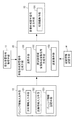
第1の実施形態の3次元音響パンニング装置1は、図1のブロック図に示すように、少なくとも1つの音源Cが放射する音源音響信号s(t)を取得する音源音響信号取得手段11と、音源Cをパンニングさせるためのパンニング情報を入力するパンニング情報入力手段12と、音源Cの位置に音像を形成する音像形成音響信号q(t)を出力する音像形成音響信号出力手段13と、音像形成音響信号出力手段13の配置情報Isを記憶する配
置情報記憶手段14と、音源音響信号s(t)、パンニング情報Ipおよび配置情報Isに基づいて音像形成音響信号q(t)を生成する音像形成音響信号生成手段15とを含んでいる。
(First embodiment)
As shown in the block diagram of FIG. 1, the three-dimensional
そして、パンニング情報入力手段12は、受音点Gを基準とする音源の方向情報Ipdを入力する方向情報入力手段121と、受音点Gを基準とする音源までの距離情報Iprを入力する距離情報入力手段122とを含んでいてもよい。 The panning information input means 12 inputs direction information input means 121 for inputting sound source direction information I pd with the sound receiving point G as a reference, and distance information I pr to the sound source with the sound receiving point G as a reference. And distance information input means 122 may be included.
パンニング情報入力手段12は、さらに、パンニング情報Ipを記憶するパンニング情報記憶手段123を含んでいてもよい。
The panning
また、音像形成音響信号出力手段13は、音像形成音響信号q(t)を記録し編集する記録編集手段131を含んでいてもよい。 The sound image forming sound signal output means 13 may include a recording / editing means 131 for recording and editing the sound image forming sound signal q (t).
音像形成音響信号生成手段15は、音源音響信号s(t)を周波数領域音源音響信号S(ω)にフーリエ変換する変換手段151と、周波数領域音源音響信号S(ω)、パンニング情報Ipおよび配置情報Isに基づいてパンニングする音像を形成する周波数領域音像形成音響信号Q(ω)を生成する周波数領域音像形成音響信号生成手段152と、周波数領域音像形成音響信号Q(ω)を時間関数である音像形成音響信号q(t)にフーリエ逆変換する逆変換手段153とを含む。
The sound image forming sound signal generating means 15 includes a transforming
図2は、本発明に係る3次元音響パンニング装置1のハードウエア構成を示すブロック図であって、音源音響信号s(t)を読み込むアナログ・デジタル(A/D)変換器21と、音像形成音響信号q(t)を出力するデジタル・アナログ(D/A)変換器22と、3次元音響パンニングプログラムを実行するCPU23と、3次元音響パンニングプログラムを記憶するメモリ24と、3次元音響パンニング装置を操作するための周辺機器が接続されるインターフェイス(I/F)25とがバス20に接続された構成を有する。
FIG. 2 is a block diagram showing a hardware configuration of the three-dimensional
I/F25には、表示パネル261と、キーボード262と、マウス263と、パンニング情報Ipの方向成分情報を入力するトラックボール27と、パンニング情報Ipの距離成分情報を入力するパンポッド28とが接続される。なお、表示パネル261、キーボード262、およびマウス263に代えて、専用の操作パネルを適用することも可能である。
The I / F25, and the
即ち、本発明に係る3次元音響パンニング装置1は、コンピュータ2に3次元音響パンニングプログラムをインストールすることにより構成される。
That is, the three-dimensional
図3はトラックボール27(a)およびパンポッド28(b)の斜視図である。 FIG. 3 is a perspective view of the trackball 27 (a) and the pan pod 28 (b).
トラックボール27は、トラックボールベース271に設けられた半球状の窪みにボール272が嵌合し、ボール272を任意の方向に回転させることが可能な構造を有する。
The
ボール272を指または掌で回転させることにより、受音点Gを基準とする音源Cの方向情報(音源の回転方向および回転量)を入力することができる。
By rotating the
パンポッド28は、例えば可変抵抗器であり、パンポッドベース281上のつまみ282を前後に移動させることにより受音点Gを基準とする音源Cまでの距離情報を入力することができる。
The
図4は、メモリ24にインストールされる3次元音響パンニングプログラムのフローチャートであって、CPU23は、まずA/D変換器21を介して、音源音響信号s(t)を読み込む(ステップS41)。
FIG. 4 is a flowchart of the three-dimensional sound panning program installed in the
CPU23は、音源音響信号s(t)をフーリエ変換して周波数領域音源音響信号S(ω)を算出(ステップS42)する。
The
次に、CPU23は、パンニング処理を実行して周波数領域音像形成音響信号Q(ω)を算出(ステップS43)し、周波数領域音像形成音響信号Q(ω)を逆フーリエ変換して時間領域の信号である音像形成音響信号q(t)を算出(ステップS44)する。
Next, the
なお、ステップS43およびステップS44の処理の詳細は後述する。 Details of the processes in steps S43 and S44 will be described later.
最後に、CPU23は、D/A変換器22を介して音像形成音響信号q(t)を出力(ステップS45)して、このルーチンを終了する。
Finally, the
ステップS43では、音源音響信号s(t)を放射する音源Cをパンニング情報Ipに基づいてパンニングしたときの受音点Gにおける音響物理量ベクトルである音源音響物理量ベクトルRに等しい音像音響物理量ベクトルVを受音点Gに形成する音像形成音響信号q(t)を生成する。 In step S43, the sound image acoustic physical quantity vector V equal to the sound source acoustic physical quantity vector R that is the acoustic physical quantity vector at the sound receiving point G when the sound source C that radiates the sound source acoustic signal s (t) is panned based on the panning information I p. Is generated at the sound receiving point G, and a sound image forming acoustic signal q (t) is generated.
まず、点音源が1つ、受音点が1つの場合における受音点の音響物理量ベクトルについて説明する。 First, an acoustic physical quantity vector at a sound receiving point when there is one point sound source and one sound receiving point will be described.
3次元空間の原点に配置された点音源から放射された音響の原点から半径rの球面上の音圧p(t,r)は[数1]の波動方程式により決定される。

よって、点音源に印加される音源音響信号をs(t)とすれば、原点から半径rの球面上の音圧p(t,r)は[数2]によって表される。
[数2]の周波数領域表現は、[数3]となる。
上式は、1つの点音源から放射された音源音響信号s(t)の1つの受音点における音圧は、点音源から受音点までの距離に反比例し、点音源から受音点までの音響信号の伝播時間遅延し、1つの受音点における音圧は点音源から受音点までの距離の関数である音圧伝達関数Gp(ω,r)と周波数領域音源音響信号S(ω)との積を逆フーリエ変換して算出できることを示している。 In the above equation, the sound pressure at one sound receiving point of the sound source acoustic signal s (t) radiated from one point sound source is inversely proportional to the distance from the point sound source to the sound receiving point, and from the point sound source to the sound receiving point. The sound pressure at one sound receiving point is the sound pressure transfer function G p (ω, r), which is a function of the distance from the point sound source to the sound receiving point, and the frequency domain sound source sound signal S ( This shows that the product with ω) can be calculated by inverse Fourier transform.
点音源から受音点までの距離および音響信号の伝播時間は、任意の座標系における点音源座標および受音点座標を定めれば一義的に定まるので、音圧伝達関数も座標系における音源座標および受音点座標を定めれば一義的に定まることとなる。 Since the distance from the point sound source to the sound receiving point and the propagation time of the acoustic signal are uniquely determined if the point sound source coordinates and the sound receiving point coordinates are determined in an arbitrary coordinate system, the sound pressure transfer function is also determined by the sound source coordinates in the coordinate system. If the sound receiving point coordinates are determined, they are uniquely determined.
3次元空間の原点に配置された点音源から放射された音源音響信号の原点から半径rの球面上の粒子速度v(r,t)とすれば、半径rの球面上の運動方程式は[数4]で表される。
[数4]を解いて、粒子速度v(r)は[数5]により表すことができる。
[数5]の周波数領域表現は[数6]となる。
従って、受音点kにおける音圧p(t,r)および粒子速度v(t,r)の双方を成分とする音響物理量ベクトルPkは[数7]によって定義することができる。
音響物理量ベクトルPkは、音圧p(t,r)または粒子速度v(t,r)の一方だけを成分としてもよい。 The acoustic physical quantity vector P k may include only one of the sound pressure p (t, r) or the particle velocity v (t, r) as a component.
さらに、音響物理量ベクトルPkは音圧p(t,r)と粒子速度v(t,r)の積である瞬時音響インテンシティII(t,r)、あるいは、瞬時音響インテンシティのある時間区間の積分値である音響インテンシティI(t,r)を成分とするものであってもよい。 Further, the acoustic physical quantity vector P k is an instantaneous acoustic intensity II (t, r) that is a product of the sound pressure p (t, r) and the particle velocity v (t, r), or a time interval in which the instantaneous acoustic intensity is present. The sound intensity I (t, r), which is the integral value of
ここで、瞬時音響インテンシティII(t,r)は[数8]で、音響インテンシティI(t,r)は[数9]で定義される。
なお、以下の実施形態においては、音響物理量ベクトルが音圧である場合について説明する。 In the following embodiments, a case where the acoustic physical quantity vector is a sound pressure will be described.
受音点Gを原点とする空間内の音源の位置をC(rc(τ),θc(τ),φc(τ))と表すと、音源Cから放射された音源音響信号の原点における音圧ベクトルである音源音圧ベクトルRは[数10]で表すことができる。
また、音像形成音響信号出力手段13である3つのスピーカSPi(i=1,2,3)の位置を、図5に示すようにSPi(ri,θi,φi)と表すと、各スピーカSPiが周波数領域音像形成音響信号Qi(ω)(i=1,2,3)を出力した時の原点における音圧ベクトルである音像音圧ベクトルVは[数11]で表すことができる。
ここで、[数12]が成立するようにQ1(ω)、Q2(ω)、Q3(ω)を決定し、時間領域に逆変換してスピーカから出力すれば、音源音響信号s(t)がパンニングする状況を、予め定められた位置に配置したスピーカから音像形成音響信号q(t)を出力することにより再現することが可能となる。
![]()
![]()
そして、[数12]が成立するように音像形成音響信号q1(t)、q2(t)、q3(t)を決定するためには、[数13]で表される音源音圧ベクトルRと音像音圧ベクトルVの二乗誤差Eが最少となる音像形成音響信号q1(t)、q2(t)、q3(t)を求めればよい。
![]()
![]()
[数13]に[数10]および[数11]を代入して展開すると[数14]となる。
[数15]を使用して[数14]を書き換えると、[数16]となる。
二乗誤差Eを最小とする周波数領域音像形成音響信号Q(ω)は、EをQ(ω)について偏微分して零とおいた[数17]により決定することができる。
よって、二乗誤差Eを最小とする周波数領域音像形成音響信号Q(ω)は[数18]となる。
以上がステップS43のパンニングルーチンの処理である。 The above is the processing of the panning routine in step S43.
ステップS44の処理として[数18]を逆フーリエ変換することにより、3つのスピーカSPiから出力する[数19]で表される音像形成音響信号qi(i=1,2,3)を算出する。
ここで、パラメータr1,r2,r3,θ1,θ2,θ3,φ1,φ2,φ3はスピーカの位置情報として与えられ、パラメータθ(τ),φ(τ)は図3(a)に示すトラックボール27を使用して入力され、パラメータr(τ)は図3(b)に示すパンポッド28を使用して入力される。
Here, the parameters r 1 , r 2 , r 3 , θ 1 , θ 2 , θ 3 , φ 1 , φ 2 , φ 3 are given as speaker position information, and the parameters θ (τ), φ (τ) are The
上記第1の実施形態によれば、受音点を頂点とし受音点と3つのスピーカのそれぞれを結ぶ直線を稜線とする三角錐内で音像をパンニングすることが可能となる。 According to the first embodiment, it is possible to pan a sound image within a triangular pyramid having a sound receiving point as a vertex and a straight line connecting each of the sound receiving point and the three speakers as a ridge line.
(第2の実施形態)
第2の実施形態は、4つ以上のスピーカを設置し、音像を任意の位置にパンニングすることを可能とするものである。
(Second Embodiment)
In the second embodiment, four or more speakers are installed, and a sound image can be panned to an arbitrary position.
図6は、8つのスピーカSP1〜SP8を設置して音像をC1〜C2にパンニングする場合を説明する斜視図であって、音像は受音点Gを頂点とし受音点Gと3つのスピーカSP2,SP3,SP4とを結ぶ線を稜線とする三角錐の音場[以下、音場(SP2,SP3,SP4)と記す]内の初期位置C1から、音場(SP3,SP4,SP6)、音場(SP4,SP5,SP6)を経由して、音場(SP5,SP6,SP7)内の最終位置C2に移動する場合を示している。 FIG. 6 is a perspective view for explaining a case where eight speakers SP 1 to SP 8 are installed and a sound image is panned to C 1 to C 2. The sound image has a sound receiving point G as a vertex and a sound receiving point G and From an initial position C 1 in a triangular pyramid sound field (hereinafter referred to as sound field (SP 2 , SP 3 , SP 4 )) whose line is a line connecting the three speakers SP 2 , SP 3 , SP 4 , Moves to the final position C 2 in the sound field (SP 5 , SP 6 , SP 7 ) via the sound field (SP 3 , SP 4 , SP 6 ) and the sound field (SP 4 , SP 5 , SP 6 ) Shows when to do.
音像の軌跡と音場の境界面との交点は予め算出することが可能であるので、各音場ごとに第1の実施形態を適用することにより任意のパンニングを実現することが可能となる。
(第3の実施形態)
第1の実施形態および第2の実施形態は、1つの音源をパンニングする場合を説明したが、本発明は相対位置が不変である複数の音源を一度にパンニングすることも可能である。
Since the intersection between the locus of the sound image and the boundary surface of the sound field can be calculated in advance, any panning can be realized by applying the first embodiment for each sound field.
(Third embodiment)
Although the first embodiment and the second embodiment have described the case of panning one sound source, the present invention can also pan a plurality of sound sources whose relative positions are unchanged.
音源がM個存在するとき、m番目の音源の位置をCm(rcm(τ),θcm(τ),φcm(τ))(1≦m≦M)とすれば、M個の音源から放射された音源音響信号による受音点Gにおける音源音圧ベクトルRは[数20]で表される。
m番目の音源Cmを含む音場を形成する3つのスピーカSPmi(i=1,2,3)の位置を、SPmi(rmi,θmi,φmi)と表すと、各スピーカSPmiが周波数領域音像形成音響信号Qmi(ω)を出力した時の受音点Gにおける音圧ベクトルである音像音圧ベクトルVm、およびM個の音源それぞれに対応する音像音圧ベクトルの重ね合わせである受音点Gにおける音像音圧ベクトルVは[数21]で表される。
よって、[数10]に代えて[数20]を、[数11]に代えて[数21]を使用して第1の実施形態および第2の実施形態を適用すれば、相対位置が不変である複数の音源を一度にパンニングする状況を再現することが可能となる。 Therefore, if the first and second embodiments are applied using [Equation 20] instead of [Equation 10] and [Equation 21] instead of [Equation 11], the relative position remains unchanged. It is possible to reproduce the situation of panning a plurality of sound sources at once.
(第4の実施形態)
第4の実施形態は、本発明に係る3次元音響パンニング装置にテレビ番組あるいはラジオ番組の制作に利用するときに必要な機能を追加したものであって、パンニング情報Ipを記憶するパンニング情報記憶手段123および音像形成音響信号q(t)を記録し編集する記録編集手段131を含む。
(Fourth embodiment)
In the fourth embodiment, functions necessary for use in the production of a television program or a radio program are added to the three-dimensional sound panning apparatus according to the present invention, and the panning information storage for storing the panning information I p is used.
パンニング情報記憶手段123は、トラックボール27およびパンポッド28の操作情報であるパンニング情報Ipを記憶する機能を有し、異なる音源に同じパンニング操作を繰り返すことを可能とする。
The panning
記録編集手段131は、音像形成音響信号q(t)を記録し、重ね合わせ編集する機能を有し、複数の音源のそれぞれにパンニング操作を施した音像形成音響信号を生成することを可能とする。
The recording /
ここで、それぞれMn個の音源が存在するN個のグループの音源に対し、グループごとに異なるパンニング操作を施す場合を考える。 Here, consider a case where different panning operations are performed for each group on N groups of sound sources each having M n sound sources.
n番目のグループのmn番目の音源の位置をCmn(rcmn(τ),θcmn(τ),φcmn(τ))(1≦mn≦Mn)とすれば、Mn個の音源から放射される音源音響信号により形成される受音点Gの音源音圧ベクトルRnおよび全NグループのM1+M2+・・・+MN個の音源から放射される音源音響信号により形成される受音点Gの音源音圧ベクトルRは[数22]で表される。
n番目のグループのmn番目の音源Cmnを含む音場を形成する3つのスピーカSPmni(i=1,2,3)の位置を、SPmni(rmni,θmni,φmni)と表すと、各スピーカSPmniが周波数領域音像形成音響信号Qmni(ω)を出力した時の受音点Gにおける音圧ベクトルである音像音圧ベクトルVmn、n番目のグループのMn個の音源に対応する音像音圧ベクトルの重ね合わせである受音点Gにおける音像音圧ベクトルVn、および全Nグループの音源に対応する音像音圧ベクトルの重ね合わせである受音点Gにおける音像音圧ベクトルVは[数23]で表される。
よって、[数10]に代えて[数22]を、[数11]に代えて[数23]を使用して第1の実施形態および第2の実施形態を適用すれば、複数の音源をそれぞれパンニングする状況を再現することが可能となる。 Therefore, by applying [Equation 22] instead of [Equation 10] and [Equation 23] instead of [Equation 11], applying the first embodiment and the second embodiment, a plurality of sound sources can be obtained. Each panning situation can be reproduced.
以上のように、本発明に係る3次元音響パンニング装置は、音源が3次元的にパンニングする状況を予め定められた位置に配置されたスピーカを使用して再生することのできるという効果を有し、音響信号処理装置等として有効である。 As described above, the three-dimensional sound panning apparatus according to the present invention has an effect that the situation in which the sound source is panned three-dimensionally can be reproduced using the speaker arranged at a predetermined position. It is effective as an acoustic signal processing device.
1 3次元音響パンニング装置
11 音源音響信号取得手段
12 パンニング情報入力手段
13 音像形成音響信号出力手段
14 配置情報記憶手段
15 音像形成音響信号生成手段
121 方向情報入力手段
122 距離情報入力手段
123 パンニング情報記憶手段
131 記録編集手段
151 変換手段
152 周波数領域音像形成音響信号生成手段
153 逆変換手段
DESCRIPTION OF
Claims (4)
前記音源をパンニングさせるためのパンニング情報を入力するパンニング情報入力手段と、
前記音源の位置に音像を形成する音像形成音響信号を出力する音像形成音響信号出力手段と、
前記音像形成音響信号出力手段の配置情報を記憶する配置情報記憶手段と、
前記音源音響信号、前記パンニング情報および前記配置情報に基づいて前記音像形成音響信号を生成する音像形成音響信号生成手段と、を含み、
前記音像形成音響信号生成手段が、
前記音源音響信号を周波数領域音源音響信号にフーリエ変換する変換手段と、
前記周波数領域音源音響信号、前記パンニング情報および前記配置情報に基づいて周波数領域音像形成音響信号を生成する周波数領域音像形成音響信号生成手段と、
前記周波数領域音像形成音響信号を時間関数である前記音像形成音響信号にフーリエ逆変換する逆変換手段と、を含み、
前記周波数領域音像形成音響信号生成手段が、
前記音源音響信号を放射する前記音源をパンニング情報に基づいてパンニングしたときの受音点における音響物理量ベクトルである音源音響物理量ベクトルに等しい音像音響物理量ベクトルを受音点に形成する前記音像形成音響信号を生成するものである3次元音響パンニング装置。 Sound source sound signal acquisition means for acquiring a sound source sound signal emitted by at least one sound source;
Panning information input means for inputting panning information for panning the sound source;
Sound image forming acoustic signal output means for outputting a sound image forming acoustic signal for forming a sound image at the position of the sound source;
Arrangement information storage means for storing arrangement information of the sound image forming acoustic signal output means;
The sound source audio signals, look including a sound image forming acoustic signal generation means for generating said sound image forming acoustic signal based on the panning information and the layout information,
The sound image forming acoustic signal generating means,
A transforming means for Fourier transforming the sound source acoustic signal into a frequency domain sound source acoustic signal;
A frequency domain sound image forming acoustic signal generating means for generating a frequency domain sound image forming acoustic signal based on the frequency domain sound source acoustic signal, the panning information and the arrangement information;
An inverse transform means for Fourier transforming the frequency domain sound image forming sound signal into the sound image forming sound signal that is a time function;
The frequency domain sound image forming acoustic signal generating means,
The sound image forming acoustic signal that forms a sound image acoustic physical quantity vector equal to a sound source acoustic physical quantity vector that is an acoustic physical quantity vector at a sound receiving point when the sound source emitting the sound source acoustic signal is panned based on panning information. A three-dimensional acoustic panning device that generates
前記受音点を基準とする前記音源の方向情報を入力する方向情報入力手段と、
前記受音点を基準とする前記音源までの距離情報を入力する距離情報入力手段とを含む請求項1に記載の3次元音響パンニング装置。 The panning information input means is
And direction information input means for inputting direction information of the sound source relative to the said sound receiving point,
The three-dimensional sound panning apparatus according to claim 1, further comprising distance information input means for inputting distance information to the sound source based on the sound receiving point.
前記パンニング情報を記憶するパンニング情報記憶手段を含む請求項2に記載の3次元音響パンニング装置。 The panning information input means is
The three-dimensional acoustic panning apparatus according to claim 2, further comprising panning information storage means for storing the panning information.
前記音像形成音響信号を記録し編集する記録編集手段を含む請求項1から請求項3のいずれか一項に記載の3次元音響パンニング装置。 The sound image forming acoustic signal output means,
The three-dimensional sound panning apparatus according to any one of claims 1 to 3, further comprising recording / editing means for recording and editing the sound image forming sound signal.
Priority Applications (4)
| Application Number | Priority Date | Filing Date | Title |
|---|---|---|---|
| JP2006159925A JP5010185B2 (en) | 2006-06-08 | 2006-06-08 | 3D acoustic panning device |
| US12/160,995 US8249283B2 (en) | 2006-01-19 | 2007-01-19 | Three-dimensional acoustic panning device |
| AU2007207861A AU2007207861B2 (en) | 2006-01-19 | 2007-01-19 | Three-dimensional acoustic panning device |
| PCT/JP2007/050781 WO2007083739A1 (en) | 2006-01-19 | 2007-01-19 | Three-dimensional acoustic panning device |
Applications Claiming Priority (1)
| Application Number | Priority Date | Filing Date | Title |
|---|---|---|---|
| JP2006159925A JP5010185B2 (en) | 2006-06-08 | 2006-06-08 | 3D acoustic panning device |
Publications (3)
| Publication Number | Publication Date |
|---|---|
| JP2007329746A JP2007329746A (en) | 2007-12-20 |
| JP2007329746A5 JP2007329746A5 (en) | 2009-01-08 |
| JP5010185B2 true JP5010185B2 (en) | 2012-08-29 |
Family
ID=38929911
Family Applications (1)
| Application Number | Title | Priority Date | Filing Date |
|---|---|---|---|
| JP2006159925A Active JP5010185B2 (en) | 2006-01-19 | 2006-06-08 | 3D acoustic panning device |
Country Status (1)
| Country | Link |
|---|---|
| JP (1) | JP5010185B2 (en) |
Families Citing this family (11)
| Publication number | Priority date | Publication date | Assignee | Title |
|---|---|---|---|---|
| JP4922211B2 (en) * | 2008-03-07 | 2012-04-25 | 日本放送協会 | Acoustic signal converter, method and program thereof |
| JP5401864B2 (en) * | 2008-08-01 | 2014-01-29 | ヤマハ株式会社 | Acoustic apparatus and program |
| JP2010252220A (en) * | 2009-04-20 | 2010-11-04 | Nippon Hoso Kyokai <Nhk> | Three-dimensional acoustic panning apparatus and program therefor |
| JP5472613B2 (en) * | 2009-12-28 | 2014-04-16 | 公立大学法人会津大学 | Stereophonic sound generation system, control method thereof, and control program |
| EP3840421A1 (en) | 2013-04-26 | 2021-06-23 | Sony Corporation | Audio processing device and audio processing system |
| RU2769677C2 (en) | 2013-04-26 | 2022-04-04 | Сони Корпорейшн | Method and apparatus for sound processing |
| WO2015054033A2 (en) * | 2013-10-07 | 2015-04-16 | Dolby Laboratories Licensing Corporation | Spatial audio processing system and method |
| KR102380232B1 (en) * | 2013-10-25 | 2022-03-29 | 삼성전자주식회사 | Method and apparatus for 3D sound reproducing |
| KR102231755B1 (en) * | 2013-10-25 | 2021-03-24 | 삼성전자주식회사 | Method and apparatus for 3D sound reproducing |
| JP7088408B2 (en) * | 2019-03-25 | 2022-06-21 | ヤマハ株式会社 | Audio signal processing equipment, audio signal processing system and audio signal processing method |
| KR102443055B1 (en) * | 2021-03-18 | 2022-09-14 | 삼성전자주식회사 | Method and apparatus for 3D sound reproducing |
Family Cites Families (9)
| Publication number | Priority date | Publication date | Assignee | Title |
|---|---|---|---|---|
| JPH06311600A (en) * | 1993-04-26 | 1994-11-04 | Sanki Eng Co Ltd | Image displacement control information generating system and acoustic system |
| JP3385725B2 (en) * | 1994-06-21 | 2003-03-10 | ソニー株式会社 | Audio playback device with video |
| JP3367625B2 (en) * | 1995-01-26 | 2003-01-14 | 日本ビクター株式会社 | Sound image localization control device |
| JPH09182200A (en) * | 1995-12-22 | 1997-07-11 | Kawai Musical Instr Mfg Co Ltd | Device and method for controlling sound image |
| JP3333440B2 (en) * | 1997-11-21 | 2002-10-15 | 日本無線株式会社 | Outdoor sound field correction device |
| AU2000226583A1 (en) * | 2000-02-18 | 2001-08-27 | Bang And Olufsen A/S | Multi-channel sound reproduction system for stereophonic signals |
| JP2002159097A (en) * | 2000-11-22 | 2002-05-31 | Univ Tokyo | System and method for simulating sound field |
| JP4368054B2 (en) * | 2000-11-27 | 2009-11-18 | シャープ株式会社 | Audio signal recording apparatus and audio signal recording / reproducing apparatus |
| JP4594681B2 (en) * | 2004-09-08 | 2010-12-08 | ソニー株式会社 | Audio signal processing apparatus and audio signal processing method |
-
2006
- 2006-06-08 JP JP2006159925A patent/JP5010185B2/en active Active
Also Published As
| Publication number | Publication date |
|---|---|
| JP2007329746A (en) | 2007-12-20 |
Similar Documents
| Publication | Publication Date | Title |
|---|---|---|
| JP5010185B2 (en) | 3D acoustic panning device | |
| JP6721096B2 (en) | Audio processing device and method, and program | |
| US8249283B2 (en) | Three-dimensional acoustic panning device | |
| JP4651710B2 (en) | Apparatus and method for generating and processing sound effects in a spatial sound reproduction system by means of a graphic user interface | |
| EP1473971B1 (en) | Sound field controller | |
| JP2010252220A (en) | Three-dimensional acoustic panning apparatus and program therefor | |
| JP5010148B2 (en) | 3D panning device | |
| EP3313101B1 (en) | Distributed spatial audio mixing | |
| JP2008017117A (en) | Audio image forming device | |
| JP5543106B2 (en) | Spatial audio signal reproduction apparatus and spatial audio signal reproduction method | |
| JP4886242B2 (en) | Downmix device and downmix program | |
| CN109716794B (en) | Information processing apparatus, information processing method, and computer-readable storage medium | |
| JP2023024471A (en) | Information processor and method for processing information | |
| JP2005522761A (en) | Wireless acoustic-based pointer device (such as a computer mouse) that controls the cursor on the display screen | |
| CN109618276B (en) | Sound field reconstruction method, device, storage medium and device based on non-central point | |
| JP2009218655A (en) | Acoustic signal conversion device, method thereof, and program thereof | |
| WO2020203343A1 (en) | Information processing device and method, and program | |
| Grani et al. | Spatial sound and multimodal interaction in immersive environments | |
| JP6056466B2 (en) | Audio reproducing apparatus and method in virtual space, and program | |
| JP4484570B2 (en) | Acoustic information processing apparatus and acoustic information providing method | |
| WO2021241421A1 (en) | Sound processing method, sound processing device, and sound processing program | |
| Bergner et al. | Application of wave field synthesis in virtual acoustic engineering | |
| JP3653360B2 (en) | Method and apparatus for creating computer generated hologram | |
| JPWO2019208285A1 (en) | Sound image reproduction device, sound image reproduction method and sound image reproduction program | |
| JP2932801B2 (en) | 3D sound field simulation method |
Legal Events
| Date | Code | Title | Description |
|---|---|---|---|
| A521 | Request for written amendment filed |
Free format text: JAPANESE INTERMEDIATE CODE: A523 Effective date: 20081114 |
|
| A621 | Written request for application examination |
Free format text: JAPANESE INTERMEDIATE CODE: A621 Effective date: 20081114 |
|
| A131 | Notification of reasons for refusal |
Free format text: JAPANESE INTERMEDIATE CODE: A131 Effective date: 20110816 |
|
| A521 | Request for written amendment filed |
Free format text: JAPANESE INTERMEDIATE CODE: A523 Effective date: 20111006 |
|
| A521 | Request for written amendment filed |
Free format text: JAPANESE INTERMEDIATE CODE: A821 Effective date: 20111006 |
|
| TRDD | Decision of grant or rejection written | ||
| A01 | Written decision to grant a patent or to grant a registration (utility model) |
Free format text: JAPANESE INTERMEDIATE CODE: A01 Effective date: 20120508 |
|
| A01 | Written decision to grant a patent or to grant a registration (utility model) |
Free format text: JAPANESE INTERMEDIATE CODE: A01 |
|
| A61 | First payment of annual fees (during grant procedure) |
Free format text: JAPANESE INTERMEDIATE CODE: A61 Effective date: 20120601 |
|
| R150 | Certificate of patent or registration of utility model |
Ref document number: 5010185 Country of ref document: JP Free format text: JAPANESE INTERMEDIATE CODE: R150 Free format text: JAPANESE INTERMEDIATE CODE: R150 |
|
| FPAY | Renewal fee payment (event date is renewal date of database) |
Free format text: PAYMENT UNTIL: 20150608 Year of fee payment: 3 |
|
| R250 | Receipt of annual fees |
Free format text: JAPANESE INTERMEDIATE CODE: R250 |
|
| R250 | Receipt of annual fees |
Free format text: JAPANESE INTERMEDIATE CODE: R250 |
|
| R250 | Receipt of annual fees |
Free format text: JAPANESE INTERMEDIATE CODE: R250 |
|
| R250 | Receipt of annual fees |
Free format text: JAPANESE INTERMEDIATE CODE: R250 |
|
| R250 | Receipt of annual fees |
Free format text: JAPANESE INTERMEDIATE CODE: R250 |
|
| R250 | Receipt of annual fees |
Free format text: JAPANESE INTERMEDIATE CODE: R250 |
|
| R250 | Receipt of annual fees |
Free format text: JAPANESE INTERMEDIATE CODE: R250 |
|
| R250 | Receipt of annual fees |
Free format text: JAPANESE INTERMEDIATE CODE: R250 |
|
| R250 | Receipt of annual fees |
Free format text: JAPANESE INTERMEDIATE CODE: R250 |
|
| R250 | Receipt of annual fees |
Free format text: JAPANESE INTERMEDIATE CODE: R250 |